

Page 1
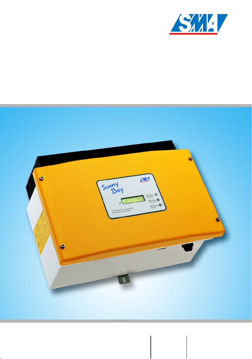
Sunny Boy SB 1100LV
Inverter for Photovoltaic Plants
Installation Guide Version 1.1 SB1100LV-11:SE2006
IME-SB1100LV
Page 2

Page 3

SMA Technologie AG Table of Contents
Inhaltsverzeichnis
1 Explanation of the symbols used: . . . . . . . . . . . . 5
2 Foreword. . . . . . . . . . . . . . . . . . . . . . . . . . . . . . . 7
2.1 Target group . . . . . . . . . . . . . . . . . . . . . . . . . . . . . 7
3 Safety instructions . . . . . . . . . . . . . . . . . . . . . . . . 9
4 Overview. . . . . . . . . . . . . . . . . . . . . . . . . . . . . . 11
4.1 Unit description . . . . . . . . . . . . . . . . . . . . . . . . . . 11
4.2 External dimensions . . . . . . . . . . . . . . . . . . . . . . . 12
5 Installation requirements . . . . . . . . . . . . . . . . . . 13
5.1 Installation site requirements . . . . . . . . . . . . . . . . . 13
5.2 PV generator requirements. . . . . . . . . . . . . . . . . . . 15
5.3 Low voltage grid (AC). . . . . . . . . . . . . . . . . . . . . . 15
6 Installation . . . . . . . . . . . . . . . . . . . . . . . . . . . . . 19
6.1 Mounting the unit . . . . . . . . . . . . . . . . . . . . . . . . . 19
6.2 Electrical installation . . . . . . . . . . . . . . . . . . . . . . . 20
6.2.1 Connecting the AC output. . . . . . . . . . . . . . . . . . . . . . . . . . . .21
6.2.2 PV string (DC) connection . . . . . . . . . . . . . . . . . . . . . . . . . . . .26
6.3 Reverse current. . . . . . . . . . . . . . . . . . . . . . . . . . . 27
6.4 Commissioning. . . . . . . . . . . . . . . . . . . . . . . . . . . 30
7 Opening and closing the Sunny Boy . . . . . . . . . 33
7.1 Opening the Sunny Boy . . . . . . . . . . . . . . . . . . . . 33
7.2 Closing the Sunny Boy . . . . . . . . . . . . . . . . . . . . . 33
8 Technical data . . . . . . . . . . . . . . . . . . . . . . . . . . 35
8.1 PV generator connection data . . . . . . . . . . . . . . . . 35
8.2 Grid connection data . . . . . . . . . . . . . . . . . . . . . . 36
8.3 Device description . . . . . . . . . . . . . . . . . . . . . . . . 37
8.4 Operating parameters. . . . . . . . . . . . . . . . . . . . . . 38
Installation Guide SB1100LV-11:SE2006 Page 3
Page 4

Table of Contents SMA Technologie AG
8.4.1 Explanation of the operating parameters . . . . . . . . . . . . . . . . .38
8.4.2 Parameter settings for Germany. . . . . . . . . . . . . . . . . . . . . . . .41
8.4.3 Country-specific parameter settings . . . . . . . . . . . . . . . . . . . . .42
8.4.4 Non-modifiable parameters. . . . . . . . . . . . . . . . . . . . . . . . . . .43
9 Certificates . . . . . . . . . . . . . . . . . . . . . . . . . . . . . 45
9.1 CE declaration of conformity . . . . . . . . . . . . . . . . . 45
9.2 SMA grid guard certificate . . . . . . . . . . . . . . . . . . 46
10 Replacing the varistors. . . . . . . . . . . . . . . . . . . . 47
11 Rating for a line circuit breaker . . . . . . . . . . . . . 51
12 The communications interface . . . . . . . . . . . . . . 55
12.1 Connection of the interface . . . . . . . . . . . . . . . . . . 56
12.1.1 Jumper functions . . . . . . . . . . . . . . . . . . . . . . . . . . . . . . . . . .57
13 Contact. . . . . . . . . . . . . . . . . . . . . . . . . . . . . . . . 59
Page 4 SB1100LV-11:SE2006 Installation Guide
Page 5

SMA Technologie AG Explanation of the symbols used:
1 Explanation of the symbols used:
To ensure optimum use of these instructions, please note the following explanation of
symbols used.
This symbol identifies an example.
This symbol identifies a notice where failure to follow the advice will make the
procedure or operation more difficult.
This symbol indicates a fact that when not observed could result in
damage to components or danger to persons. Please read these sections
especially carefully.
Installation Guide SB1100LV-11:SE2006 Page 5
Page 6

Explanation of the symbols used: SMA Technologie AG
Page 6 SB1100LV-11:SE2006 Installation Guide
Page 7
SMA Technologie AG Foreword
2 Foreword
The Sunny Boy SB 1100LV contains the SMA grid guard 2. This is a type of
independent disconnection device. It ensures that the Sunny Boy SB 1100LV
complies with the VDEW (Verband der Elektrizitätswirtschaft – German Electricity
Industry Association) regulations for the connection and parallel operation of
electrical power units to the low-voltage grid of the electricity supply company and
with DIN VDE 0126-1-1, which forms a part of these regulations.
For detailed information on troubleshooting and on how to use the Sunny Boy and the
various communications options, please see the operating instructions.
"Sunny Design" helps you design the system and check string size taking the relevant
inverter into consideration. Further information on Sunny Design is available at
www.SMA.de.
If you require further information, please call the Sunny Boy hotline on the following
number:
(0561) 95 22 - 499
2.1 Target group
Attention!
The Sunny Boy may only be installed by trained specialists. Installers must
be approved by the local energy supplier. Please carefully read this
installation manual. All prescribed safety regulations, the technical
connection requirements of the local energy supplier and all applicable
provisions must be adhered to.
This installation manual is intended solely for qualified electricians. Its aim is to help
install and set up SMA Sunny Boy SB 1100LV inverters quickly and correctly.
Installation Guide SB1100LV-11:SE2006 Page 7
Page 8

Foreword SMA Technol og ie AG
Page 8 SB1100LV-11:SE2006 Installation Guide
Page 9
SMA Technologie AG Safety instructions
3 Safety instructions
Caution! Overvoltage
Check the system design using the "Sunny
Design" design tool (www.SMA.de) or by
calling the Sunny Boy Hotline.
Overvoltages may lead to the destruction
of the Sunny Boy SB 1100LV.
Warning! High voltage!
Work on the Sunny Boy with the cover removed must be carried out by a
qualified electrician. High voltages are present in the device. Before
working on the Sunny Boy with the cover removed, the AC and DC
voltages must be disconnected from the Sunny Boy and the capacitors
must be discharged.
The Sunny Boy must be disconnected from the mains grid and precautions
must be taken to prevent the grid being reconnected. In addition, the
connections to the PV generator must be disconnected.
After isolating the AC and DC voltage, you must wait approx. 30 minutes
for the capacitors in the Sunny Boy to discharge. Only then is it safe to
open the unit by removing the cover. You must also make sure that no
voltage is present in the device.
Caution! Electrostatic charge!
When working on the Sunny Boy SB 1100LV and handling the
components, remember to observe all ESD safety regulations. Electronic
components are susceptible to electrostatic charge. Discharge any
electrostatic charge by touching the grounded enclosure before handling
any electronic component.
Installation Guide SB1100LV-11:SE2006 Page 9
Page 10

Safety instructions SMA Technologie AG
Page 10 SB1100LV-11:SE2006 Installation Guide
Page 11

SMA Technologie AG Overview
4 Overview
4.1 Unit description
The following diagram gives a schematic overview of the various components and
connection points inside the Sunny Boy SB 1100LV with the cover removed:
Varistors,
page 47
Socket for communication
(RS232, RS485, NLM PiggyBack, Radio), page 59
Sunny Display
Operating status
LEDs
Jumper for
communication
Connection plug
(AC), page 21
PV input terminal
(DC), page 26
Communications
connector
Installation Guide SB1100LV-11:SE2006 Page 11
PE (protective earth)
connecting cable for
cover
Flat connection for grounding the
cable shield for RS232 and
RS485 communications
Page 12

Overview SMA Technologie AG
4.2 External dimensions
214 mm
434 mm
295 mm
Page 12 SB1100LV-11:SE2006 Installation Guide
Page 13
SMA Technologie AG Installation requirements
5 Installation requirements
Please check that all of the conditions listed below are met before installing and setting
up the Sunny Boy.
5.1 Installation site requirements
The Sunny Boy SB 1100LV weighs approx. 29 kg. Please take this
weight into account when choosing the installation site and method
of installation.
29 kg
The ambient temperature must not be outside the -25 °C to +60 °C range.
The Sunny Boy SB 1100LV should be installed in a place where it is not exposed to
direct sunlight. An increased ambient temperature can reduce the yield of the PV
system.
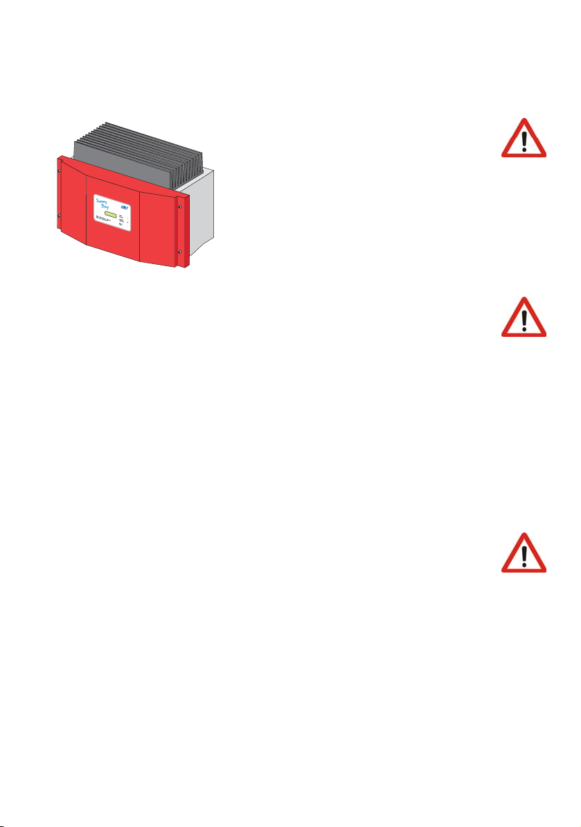
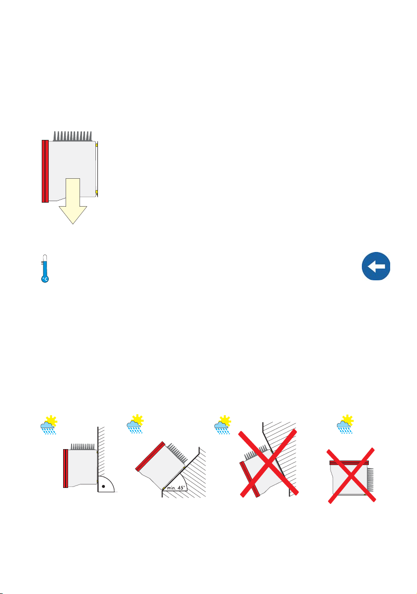
The Sunny Boy is designed to be mounted on a vertical wall. If absolutely necessary,
however, the Sunny Boy can be installed tilted back at a maximum angle of 45°. For
an optimum energy yield and the most convenient operation, vertical installation at eyelevel is preferable. If installing the unit outdoors, make sure that it is not slanting forward.
The rear panel is designed such that the Sunny Boy SB 1100LV is tilting slightly
backward on a perfectly vertical wall.
We advise against installing the unit in a horizontal position outdoors.
Install the inverter vertically or tilting
backward.
Installation Guide SB1100LV-11:SE2006 Page 13
Never install the inverter horizontally
or so that it tilts forward.
Page 14

Installation requirements SMA Technologie AG
When choosing the installation site, be sure to note the following:
Warning! Risk of burns!
The temperature of individual parts of the case and components within the
Sunny Boy can reach more than 60 °C. Touching could result in burns!
Do not install the Sunny Boy on flammable construction materials, in areas
where highly inflammable materials are stored or in potentially explosive
environments!
When choosing the installation site, ensure there is enough space for heat to dissipate.
Under normal conditions, the following guidelines should be applied for the space to
be kept clear around the Sunny Boy SB 1100LV:
Minimum clearance
Sides 20 cm
Top 20 cm
Underneath 20 cm
Front 5 cm
In domestic installations, the unit should not be
mounted on plasterboard walls or similar as
otherwise audible vibrations are likely to result.
We recommend securing the unit to a solid surface.
The Sunny Boy makes noises when in use which can,
in the domestic setting, be seen as a nuisance.
Page 14 SB1100LV-11:SE2006 Installation Guide
Page 15

SMA Technologie AG Installation requirements
W
bl
5.2 PV generator requirements
The Sunny Boy SB 1100LV is internally designed to be connected directly to up to two
strings (PV modules wired in series) having a homogenous structure (modules of the
same type, identical orientation and tilt).
For connecting the PV generators, the unit has two DC terminal blocks, which each have
connections for two strings. If you want to connect more than two strings to the Sunny
Boy SB 1100LV, you must use a DC distribution box.
The DC side must be equipped with a DC circuit breaker compliant to DIN VDE 0100712 to allow the PV generator to be disconnected from the Sunny Boy.
The Sunny Boy SB 1100LV operates with high currents on the DC side. If there is
a fault in a string, the current of this string is routed via another string as reverse
current. This can irreparably damage the PV generators. See chapter 6.3
"Reverse current" (Page 27) for more information.
"Sunny Design" helps you design the system and check string size taking the relevant
inverter into consideration. Further information on "Sunny Design" is available at
www.SMA.de.
Limit values for DC input
Max. voltage 60 V (DC)
Max. input current 62 A (DC)
5.3 Low voltage grid (AC)
The Sunny Boy must have a three-conductor connection to the mains grid (live (L),
neutral (N), protective earth (PE)).
The grid connection terminals on the AC connection
socket included in the accessories kit can take wires
with a cross-section of up to 2.5 mm². The
accessories kit also contains a PG13.5 AC
connection socket for connecting cables with a cable
diameter between 9 mm and 13.5 mm, while the
PG16 connection socket is used for cables with cable
diameters from 13.5 mm up to a maximum of 17 mm. For detailed instructions, see
chapters "Connecting the AC output with PG13.5" (Page 22) and "Connecting the AC
plug with PG16" (Page 24).
Installation Guide SB1100LV-11:SE2006 Page 15
e
Ca
diameter
ire
cross-section
Page 16
Installation requirements SMA Technologie AG
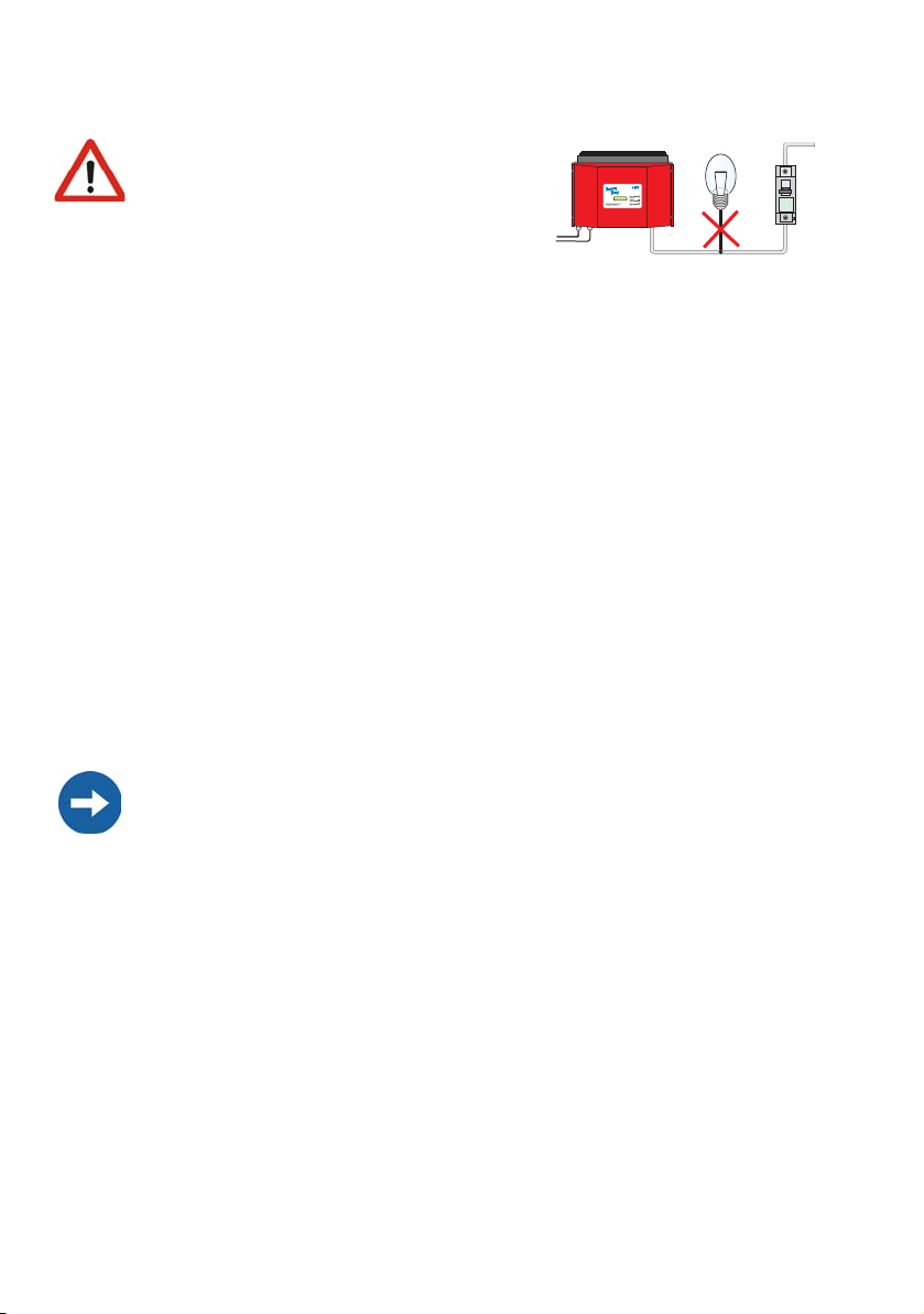
Attention!
We recommend using a 16 A line circuit
breaker to protect the power circuit. No
loads should be connected to this power
circuit.
Rating for a line circuit breaker in a photovoltaic electrical power unit
operated in parallel with the low-voltage grid
Various factors should be taken into account when selecting line circuit breakers. These
include, for example:
• The type of cable used (conductor material and insulation)
• Ambient temperatures affect the cables (higher temperatures result in a reduced
maximum current load)
• Method of routing the cable (reduces the ampacity of the conductor)
• Bundling cables together (reduces the ampacity of the conductor)
• Loop impedance [Z] (in the event of a body contact this limits the current that can
flow and therefore determines the response behavior of the circuit breaker)
• Sufficient distance between the circuit breakers so as to avoid undue heating (heat
can trigger the circuit breakers early).
• Selectivity
• Protection class of the connected load (VDE 0100, part 410, Protection against
electric shock)
Please pay attention to chapter 11 "Rating for a line circuit breaker" (Page 51).
The following standards should be followed in all cases:
• DIN VDE 0298-4 (Cable routing and current-carrying capacity)
• DIN VDE 0100; part 430 (Protective measures; protection of cable and cords
against overcurrent)
• DIN VDE 0100; part 410 (Protective measures; protection against electric
shock)
Page 16 SB1100LV-11:SE2006 Installation Guide
Page 17
SMA Technologie AG Installation requirements
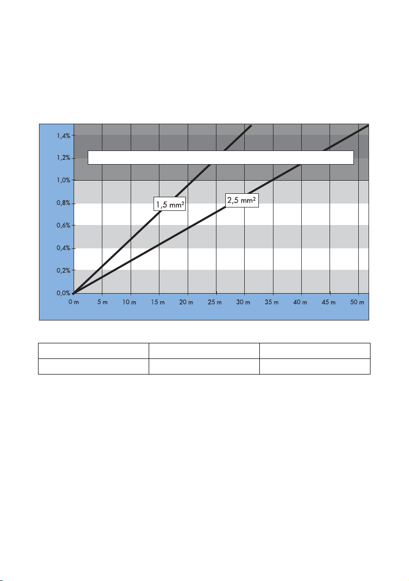
AC cable system impedance should not exceed 1 ohm. This is necessary, amongst other
things, for the correct operation of impedance observation. In addition, we recommend
dimensioning the conductor cross-section so that line losses do not exceed 1% at the
nominal power. Line losses depending on the cable length and cross-section are shown
in the graph below. Multi-wire cables with copper forward and return conductors are
used.
Do not use cables where the losses will exceed 1.0%
Line losses
Cable length
The maximum cable lengths for the different cable cross-sections are as follows:
Conductor cross-section 1.5 mm² 2.5 mm²
Max. length 21 m 35 m
Installation Guide SB1100LV-11:SE2006 Page 17
Page 18
Installation requirements SMA Technologie AG
The Sunny Boy SB 1100LV is designed for operation on 220 - 240 V grids with a grid
frequency of 50 Hz. When connecting an inverter to the public grid, please adhere to
the local connection requirements of your grid operator.
Limit values for AC output
Voltage range
198 V ... 253 / 260 V
a
(complying with DIN VDE 0126-1-1)
Frequency range
47.55 Hz ... 50.2 Hz
(complying with DIN VDE 0126-1-1)
Voltage range
180 V ... 265 V
(extended operating range)
Frequency range
45.5 Hz ... 54.5 Hz
(extended operating range)
a The Sunny Boy can feed into the public grid at a maximum output voltage of
260 V for brief periods. However, DIN VDE 0126-1-1 stipulates that the
average voltage over 10 minutes must not exceed 253 V. I.e., if the grid
voltage remains constant at 254 V, the inverter is automatically disconnected
from the grid. In this case, contact the local grid operator for assistance.
DIN VDE 0126-1-1 only applies in Germany. See chapter 8.4.3 "Countryspecific parameter settings" (Page 42) for the country-specific preset default
values of your inverter.
Page 18 SB1100LV-11:SE2006 Installation Guide
Page 19
SMA Technologie AG Installation
6 Installation
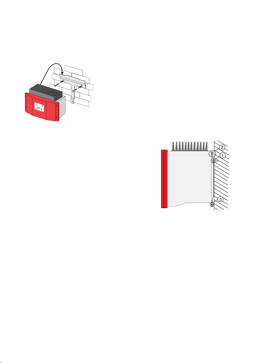
6.1 Mounting the unit
To make the job easier, we recommend you use the
supplied wall bracket to mount the Sunny Boy SB
1100LV. For vertical installation on solid concrete or
block walls, for example, you can fit the bracket
using 8 mm x 50 mm hexagon bolts to DIN 571
standard, stainless steel type, and with wall plugs
type SX8.
When selecting the mounting materials, be sure to
take into account the weight of the Sunny Boy SB
1100LV (29 kg).
1. Fit the wall bracket (1). To mark the positions to
drill the holes, you can use the wall bracket as
a drilling template.
2. Now hook the Sunny Boy SB 1100LV onto the
wall bracket (2) at its upper mounting plate so
that it cannot be moved sideways.
3. Fix the Sunny Boy SB 1100LV onto its bracket
by screwing the supplied M6x10 bolt into the
central threaded hole at the bottom of the
bracket (3).
4. Make sure the Sunny Boy SB 1100LV is
positioned securely on the bracket.
Installation Guide SB1100LV-11:SE2006 Page 19
Page 20

Installation SMA Technologie AG
6.2 Electrical installation
Attention!
Make sure to check the polarity of the strings before connecting them!
The complete wiring for a Sunny Boy SB 1100LV is shown schematically in the following
diagram:
Circuit
max. 2.5 mm²
Communication
String
* Circuit breaker according to DIN VDE 0100-712
Page 20 SB1100LV-11:SE2006 Installation Guide
Page 21

SMA Technologie AG Installation
6.2.1 Connecting the AC output
Warning! Voltage!
Before you connect the mains cable to the AC connection socket, make
sure that no voltage is present in the cable.
A round plug connector system is used, which allows various cable diameters to be
used in the cable outlet. For this reason, the accessories kit includes a PG13.5 pressure
screw and a PG16 pressure screw. Check which screw fitting is the right one for your
AC cable.
To connect up the AC output, follow these steps:
1. Check the grid voltage. If this is constantly higher than 253 V, the Sunny Boy SB
1100LV will not be fully operational. In this case, contact the local grid operator
for assistance. The inverter can feed into the grid at an output voltage of 260 V for
brief periods. However, the average output over a 10 minute period may not
exceed 253 V.
2. Isolate the grid connection (switch the line circuit
breaker to its "off" position), make sure it cannot
be switched back on, and test to make sure no
voltage is present.
3. Now take the AC connection socket parts from the accessories kit and connect up
the cable, with shielding and insulation stripped, as described on the following
pages:
Threaded
sleeve
Sealing ring for
PG13.5
Off!
Pressure screw
for PG13.5
Socket element
Cord grip for
PG13.5
PG16 pressure
screw for large
cable diameters
Installation Guide SB1100LV-11:SE2006 Page 21
Page 22

Installation SMA Technologie AG
Connecting the AC output with PG13.5
To connect a cable with a maximum cross-section of 13.5 mm², proceed as follows.
1. Press the sealing ring into the cord grip.
2. Now slide the pressure screw over the cable first of all, followed by the cord grip
with the sealing ring in it. Now slide the threaded sleeve over the cable.
Cord grip with
sealing ring
Threaded sleeve
3. Now connect the individual conductors to the socket element in sequence.
- Protective earth PE (green/yellow) to the screw terminal
with the earth sign. Make sure that the PE earth wire is
longer than the N and L connected wires.
- Neutral conductor N (blue) to screw terminal 1.
- Live L (brown or black) to screw terminal 2.
- Terminal 3 remains unused.
Sealing ring
Cord grip
Pressure screw
Terminals in the
4. Make sure the wires are securely connected.
socket element
Pressure screw
Connected wires
Cord grip with
sealing ring
Threaded sleeve
Socket element
Page 22 SB1100LV-11:SE2006 Installation Guide
Page 23

SMA Technologie AG Installation
5. Now screw the threaded sleeve onto the socket element and tighten it.
Threaded sleeve
Pressure screw
screwed onto socket
element
Cord grip with
sealing ring
6. Screw the pressure screw into the threaded
sleeve and tighten it. The cord grip with the
sealing ring is pressed into the threaded sleeve
and can no longer be seen.
Pressure screw
The AC connecting socket is now fully assembled.
If you are not going to connect up the Sunny Boy immediately, close off the socket
element using the cap supplied in the accessories kit.
If the Sunny Boy is already installed, you can now connect up the fully assembled AC
connection socket to the flange plug on the Sunny Boy. To do this, remove the protective
cap from the flange plug on the Sunny Boy. Firmly tighten the threaded ring on the AC
connecting socket to the flange plug to seal the connection and secure it.
Attention!
Do not switch the line circuit breaker on yet! The Sunny Boy SB 1100LV
may only be connected to the AC grid once the PV strings are connected
and the device is securely closed.
Installation Guide SB1100LV-11:SE2006 Page 23
Page 24

Installation SMA Technologie AG
Connecting the AC plug with PG16
To connect a cable with a cross-section between 13.5 mm² and 16 mm², proceed as
follows.
1. First of all, slide the pressure screw with the PG16 screw fitting onto the cable.
Now slide the threaded sleeve over the cable.
Pressure screw with
PG16 screw fitting
Threaded sleeve
2. Now connect the individual conductors to the socket element
in sequence.
- Protective earth PE (green/yellow) to the screw terminal
with the earth sign. Make sure that the PE earth wire is
longer than the N and L connected wires.
- Neutral conductor N (blue) to screw terminal 1.
- Live L (brown or black) to screw terminal 2.
- Terminal 3 remains unused.
3. Make sure the wires are securely connected.
Connected wires
Terminals in the
socket element
Pressure screw with
PG16 screw fitting
Threaded sleeve
Socket element
4. Now screw the threaded sleeve onto the socket element and tighten it.
Threaded sleeve screwed
onto socket element
Pressure screw with
PG16 screw fitting
Page 24 SB1100LV-11:SE2006 Installation Guide
Page 25

SMA Technologie AG Installation
5. Now screw the pressure screw into the
threaded sleeve and tighten it.
6. Firmly tighten the screw fitting against
the seal and strain relief.
Pressure screw
PG16 screw fitting
The AC connecting socket is now fully assembled.
If you are not going to connect up the Sunny Boy immediately, close off the socket
element using the cap supplied in the accessories kit.
If the Sunny Boy is already installed, you can now connect up the fully assembled AC
connection socket to the flange plug on the Sunny Boy. To do this, remove the protective
cap from the flange plug on the Sunny Boy. Firmly tighten the threaded ring on the AC
connecting socket to the flange plug to seal the connection and secure it.
Attention!
Do not switch the line circuit breaker on yet! The Sunny Boy SB 1100LV
may only be connected to the AC grid once the PV strings are connected
and the device is securely closed.
Installation Guide SB1100LV-11:SE2006 Page 25
Page 26

Installation SMA Technologie AG
6.2.2 PV string (DC) connection
To connect up the input, follow these steps:
1. Make sure the PV generator connectors have the
right polarity and do not exceed the maximum
string voltage of 60 V (DC). See also chapter
5.2 "PV generator requirements" (Page 15).
Warning!
Dangerous high voltages may be present. Danger of death!
2. Taking one DC plug connector at a time,
measure the direct current voltage between one
DC connection of a string and earth potential.
3. If the measured voltages are constant and if their
total is roughly the same as the open circuit
voltage of the string, then there is an ground fault
in this string. Its approximate location can be
deduced from the relationships between the
voltages.
Attention!
Do not connect strings to the Sunny Boy SB 1100LV that contain a ground
fault until you have fixed the earth fault in the PV generator.
4. Repeat points 2 and 3 for each string.
5. Open the Sunny Boy as described in chapter 7.1
"Opening the Sunny Boy" (Page 33).
Page 26 SB1100LV-11:SE2006 Installation Guide
Page 27

SMA Technologie AG Installation
6. Pull the cable(s) of the PV generator through the
PG screw fitting on the bottom of the inverter.
DC + must be pulled through the PG screw fitting
on the left; DC - through the one on the right.
DC -
DC -
7. There are two terminal blocks for DC connection
on the left-hand side of the inverter. Connect
DC + to the terminal block on the left and DC to the terminal block on the right. The terminals
can hold cables with a cross-section of up to
25 mm². If you are using a core end sleeve, it
may not exceed a cross-section of 16 mm².
DC +
DC +
6.3 Reverse current
Advice on generator configuration for PV systems using the Sunny Boy
SB 1100LV
The Sunny Boy SB 1100LV operates with very high input currents. This does not sound
particularly spectacular but it has practical consequences because, in such large
generators, certain faults which are totally uncritical in string systems must be allowed
for. Short circuits cause wrongly directed module current, which can lead to a PV
module being subjected to so-called reverse current, which may be several times more
than the normal maximum current (short circuit current) of the PV module.
How does reverse current occur?
In principle, reverse current can only occur when modules are connected in parallel
and the open circuit terminal voltage (Voc) of the individual parallel strings is different.
In normal operation, this is adequately avoided when the strings are of the same length.
Since shadowing of the modules has no significant effect on Voc, even in this situation
no significant reverse current occurs.
Under fault-free operation of a correctly laid out PV generator, no excessive reverse
current can occur!
Reverse current can only occur due to a fault in the solar generator (e.g. short circuit in
one or more modules) that causes the open circuit terminal voltage of a module string
to be significantly lower than the open circuit terminal voltage of other parallel strings.
In the worst case, the voltage on the faulty string may lie within the MPP voltage (VMPP)
of the remaining generator elements. The internal diode structure of the solar cells
Installation Guide SB1100LV-11:SE2006 Page 27
Page 28

Installation SMA Technologie AG
causes reverse current to flow through the faulty generator string that, depending on the
amount of current, may lead to excessive heating or destruction of the modules in this
string.
Among other symptoms, the following faults may lead to reduction of the open circuit
terminal voltage of a generator string and subsequent reverse current in parallelconnected systems:
• Short circuit in one or more modules,
• Short circuit in one or more cells in a module,
• Double ground fault in a module and/or the cabling.
Despite the fact that these faults are very unlikely, and extremely rare in practice,
preventative measures must still be taken. After all, these types of faults carry a high
potential for damage and danger, since all modules in the affected string may be
damaged and the local heating may also cause secondary damage.
Current in the faulty string =
Total current of the remaining strings
Page 28 SB1100LV-11:SE2006 Installation Guide
Page 29

SMA Technologie AG Installation
How to avoid reverse current in the modules?
First, we must know that today's state-of-the-art bypass diodes for module construction
do not affect reverse current in the module, but only reduce the effects of any shading
which may occur.
The following standard methods of preventing or reducing reverse current to the
modules exist.
1. String technology
All components in a string (modules, cable cross-section, plug connectors) must be
designed for the remaining generator short-circuit current as reverse current. This is
always the case if no more than two strings are connected in parallel, as the resulting
reverse current of a (defective) string cannot exceed the value of the short-circuit current
of the (intact) string.
2. String diodes
String diodes connected in series to the individual strings prevent any form of reverse
current in the corresponding string. Disadvantage: The diode is permanently connected
in series to the corresponding generator string, which means that the current of the string
in question always flows through it, leading to correspondingly high permanent losses.
If the diode fails, the protective function may be lost or the entire string may fail.
3. String fuses
The string fuses connected in series to the individual strings allow the reverse current in
the corresponding string to be limited to a permitted maximum value. The losses at the
string fuses are significantly lower than at the string diodes. The failure of a string fuse
can be detected by monitoring the fuse or via "intelligent" fault monitoring of the solar
generator.
For cost-effective solutions, only the first option is suitable. The PV input terminals are
approved for 62 A per connection. The system planner must ensure that this value is not
exceeded.
Installation Guide SB1100LV-11:SE2006 Page 29
Page 30

Installation SMA Technologie AG
Design instructions
The following must be tested/ensured in particular:
1. Do all strings have the same number of modules connected in series?
2. How high is the maximum reverse current in a defective string at nominal
conditions?
Example: Generator with 4 strings of modules at 5 A short-circuit current.
The maximum reverse current is 3 x 5 A = 15 A.
3. Are the modules suited for this reverse current?
4. Are the plug connectors of the modules and the inverters suited for this reverse
current?
5. Is the string wiring suited for this reverse current?
6.4 Commissioning
You can start up the Sunny Boy SB 1100LV when
• the lid is securely screwed shut,
• the AC (mains) cable is connected correctly,
• the DC cables (PV strings) are fully connected.
How to start up the inverter
1. First of all, switch the line circuit breaker and the
DC circuit breaker to the "on" position.
2. Look at the LED display and consult the table on
the following page to check whether the Sunny
Boy SB 1100LV is in a fault-free and expedient
operating mode. Once the inverter is in a faultfree operating status, start-up has successfully
completed.
Attention!
If the bottom yellow LED flashes four times at intervals of one second, the
grid voltage and the PV generator must be disconnected from the Sunny
Boy SB 1100LV immediately! There is a risk of damage to the inverter
resulting from excessive DC input voltage.
Page 30 SB1100LV-11:SE2006 Installation Guide
On
Page 31

SMA Technologie AG Installation
Check the string voltages again to make sure they are within the limits stated in chapter
5.2 "PV generator requirements" (Page 15). If the string voltages are too high, the PV
generator's planner/installer should be called upon for assistance.
If despite checking the string voltages the LED signal occurs again when the PV
generator is connected to the Sunny Boy SB 1100LV, disconnect the PV generator from
the Sunny Boy again and contact SMA Technologie AG (see chapter 13 "Contact"
(Page 59)).
Green Red Yellow Status
Illuminates
continuously
Is not illuminated Is not illuminated OK (working mode)
Illuminates
continuously
Is not illuminated Fault
Illuminates
OK (initialization)
continuously
Flashes quickly
(3x per second)
Is not illuminated Is not illuminated OK (stop)
Illuminates
Is not illuminated Fault
continuously
Flashes slowly
(1x per second)
Is not illuminated Is not illuminated OK (waiting, grid
monitoring)
Illuminates
Is not illuminated Fault
continuously
Briefly goes out
(approx.
1x per second)
Is not illuminated Is not illuminated OK (derating)
Illuminates
Is not illuminated Fault
continuously
Is not illuminated Is not illuminated Is not illuminated OK (night shutdown)
Illuminating/
Fault
flashing
Illuminates
continuously
Is not illuminated Fault
Illuminating/
Fault
flashing
For a detailed description of the fault messages and their causes, see the operating
instructions.
Installation Guide SB1100LV-11:SE2006 Page 31
Page 32

Installation SMA Technologie AG
Page 32 SB1100LV-11:SE2006 Installation Guide
Page 33

SMA Technologie AG Opening and closing the Sunny Boy
7 Opening and closing the Sunny Boy
Attention!
If you need to open the device for whatever reason, please pay attention
to chapter 3 "Safety instructions" (Page 9).
7.1 Opening the Sunny Boy
Attention!
Follow the sequence below under all circumstances.
1. Switch the line circuit breaker to the "off" position.
2. Switch the DC circuit breaker to the "off" position.
3. Wait 30 minutes!
4. Remove the four screws from the lid and pull the lid forward smoothly. Remove the
PE connection from the lid. Loosen the locking on the PE connectors on the lid when
you remove them.
7.2 Closing the Sunny Boy
Attention!
Follow the sequence below under all circumstances.
1. Reconnect the earth wire (PE) to the lid. Now secure the lid to the Sunny Boy SB
1100LV by tightening the four screws evenly.
2. Switch the DC circuit breaker to the "on" position.
3. Switch the line circuit breaker to the "on" position.
4. Now check whether the LED display on the Sunny Boy SB 1100LV indicates that
the device is functioning correctly.
Installation Guide SB1100LV-11:SE2006 Page 33
Page 34

Opening and closing the Sunny Boy SMA Technologie AG
Page 34 SB1100LV-11:SE2006 Installation Guide
Page 35

SMA Technologie AG Technical data
8 Technical data
8.1 PV generator connection data
Description Unit Setting
Max. input open circuit voltage U
Input voltage, MPP range U
Max. input current I
Max. input power P
PV 0
PV
PV max
DC
Recommended total generator
power
Connection of the DC input side DC screw terminal
Surge voltage protection Thermally monitored varistors
Voltage ripple U
ss
Insulation protection Ground fault monitoring (Riso > 1 MΩ)
Operating consumption < 4 W (standby)
Reverse polarity protection via short circuit diode
60 V
(based on -10°C cell temperature)
21 V ... 60 V
62 A
1240 W
1380 Wp (for central Europe)
< 10% of the input voltage
Installation Guide SB1100LV-11:SE2006 Page 35
Page 36

Technical data SMA Technologi e AG
8.2 Grid connection data
Description Unit Setting
Nominal output power P
ACnom
Continuous output power
(at 45 °C)
Peak output power P
Nominal output current I
Harmonic distortion of output
current (at K
0.5 P
ACNom
< 2 %, PAC >
Ugrid
)
ACmax
ACnom
K
IAC
Short-circuit strength Grid-side via current regulation
Operating range, grid voltage U
Operating range, grid frequency f
AC
AC
All-pole isolator grid side Independent disconnection device
Phase shift angle (based on the
cos phi 1
current's fundamental frequency)
Overvoltage category III
Test voltage (DC) 1.6 kV (1 s routine testing / 5 s type
Test surge voltage 4 kV (serial interface: 6 kV)
Own consumption in night mode 0.1 W
1000 W
1000 W
1100 W
4.4 A
< 4 %
180 ... 265 V AC
Germany: 198 ... 253 / 260 V AC
45.5 ... 54.5 Hz
Germany: 47.55 ... 50.2 Hz
("SMA grid guard 2"), double
implementation
testing)
a
a The Sunny Boy can feed into the public grid at a maximum output voltage of
260 V for brief periods. However, DIN VDE 0126-1-1 stipulates that the
average voltage over 10 minutes must not exceed 253 V. I.e., if the grid
voltage remains constant at 254 V, the inverter is automatically disconnected
from the grid. In this case, contact the local grid operator for assistance.
DIN VDE 0126-1-1 only applies in Germany. See chapter 8.4.3 "Countryspecific parameter settings" (Page 42) for the country-specific preset default
values of your inverter.
Page 36 SB1100LV-11:SE2006 Installation Guide
Page 37

SMA Technologie AG Technical data
8.3 Device description
For a detailed description of the devices, see the operating instructions.
General data
Protection category per DIN EN 60529 IP65
Dimensions (w x h x d) 434 mm x 295 mm x 214 mm
(approx.)
Weight 29 kg (approx.)
External interfaces
Data transmission over mains power line optional
Data transmission over separate data cable optional, RS232 / RS485,
electrically separated
Wireless data transmission optional
Efficiency
Max. efficiency ηmax 92 %
European standard efficiency ηeuro 90.4 %
The efficiency of the Sunny Boy SB 1100LV depends mainly on the input voltage of the
connected PV strings. The lower the input voltage, the higher the efficiency.
Overall efficiency [%]
Output power [W]
Installation Guide SB1100LV-11:SE2006 Page 37
Page 38

Technical data SMA Technologi e AG
8.4 Operating parameters
Warning!
Unauthorised changes to the operating parameters may result in:
• injury or accidents as a result of changing the internal safety routines
in the Sunny Boy,
• voiding the Sunny Boy's operating approval certificate,
• voiding the Sunny Boy's guarantee.
Never change the parameters of your Sunny Boy without express
authorization and instructions.
8.4.1 Explanation of the operating parameters
Name Explanation
ACVtgRPro Surge voltage protection (only relevant for Germany).
Sunny Boys can feed into the public grid with up to 260 V AC.
However, DIN VDE 0126-1-1 stipulates that the average AC
voltage over 10 minutes must not exceed 253 V. If the average
over 10 minutes exceeds the threshold value of 253 V, the
inverter disconnects itself from the grid. Once the average over
10 minutes returns to a value of less than 253 V, the inverter
returns to "Working" mode. If surge voltage protection is not
required in the relevant grid area (outside Germany), it can be
deactivated by means of presetting the LDVtgC parameter. In
this event, only the fast cut-off via the Uac-Max parameter
intervenes.
AntiIsland-Ampl Amplification of the AntiIsland process (deactivated for GER by
setting AntiIsland-Ampl = 0)
AntiIsland-Freq Repetition rate of the AntiIsland process (deactivated for GER by
setting AntiIsland-Ampl = 0)
Default Used for setting the country-specific information.
GER/VDE0126-1-1: country-specific parameter settings for
Germany in accordance with DIN VDE 0126-1-1
SP/RD1663: country-specific parameter settings for Spain
GB/G83: country-specific parameter settings for Great Britain
Other: here, parameter settings can be defined for countries for
which no predefined setting exists.
Trimmed: if country-specific parameters have been changed,
"trimmed" is shown in the display.
Page 38 SB1100LV-11:SE2006 Installation Guide
Page 39

SMA Technologie AG Technical data
Name Explanation
dFac-Max Maximum "grid frequency change" before the grid monitoring
system disconnects the device from the grid.
dZac-Max Maximum "grid impedance change" before the grid monitoring
system disconnects the device from the grid.
E_Total Total energy yield for the inverter. This change may be
necessary when you exchange the Sunny Boy and want to use
the data from the old device.
Fac-deltaFac-delta+
Maximum frequency, above (Fac-delta+) and below (Fac-delta-)
the mains frequency, before the mains monitoring system
disconnects the device from the mains supply.
Fac-Pderating Frequency-dependent output limitation
Fac-Tavg Averaging time of grid frequency gaging
h_Total Total hours of operation for the inverter. This change may be
necessary when you exchange the Sunny Boy and want to use
the data from the old device.
I-Ni-Test Setting the impulse for impedance monitoring. This parameter
only functions when the Sunny Boy is deactivated (disconnected
on the AC side) or in "Stopp" mode.
Inst.-Code Parameters for self contained power system recognition can only
be changed after entering the "SMA grid guard" password.
LDVtgC Compensation for the voltage drop in the cabling.
With this parameter, the voltage drop between the inverter and
the grid connection point is taken into account. The average
voltage over 10 minutes at the inverter connection must not
exceed the sum of ACVtgRPro plus LDVtgC. The parameter
LDVtgC is preset to 0 V for Germany. In grid areas in which the
additional surge voltage protection (see parameter ACVtgRPro)
is not required, the parameter LDVtgC is preset to 50 V. Thus, the
surge voltage protection is deactivated for these grid areas
(253 V + 50 V = 303 V) and only the fast cut-off via the UacMax parameter intervenes.
Installation Guide SB1100LV-11:SE2006 Page 39
Page 40

Technical data SMA Technologi e AG
Name Explanation
Operating mode Operating mode of the Sunny Boy:
MPP: Maximum Power Point
UKonst: Constant voltage mode (desired voltage is defined in
"Usoll-Konst")
IKonst: Operating mode for test purposes
Stopp: Disconnection from mains network, no operation
Turbine Mode: Operating mode for wind energy systems.
Off Grid: Operating mode for Sunny Boys in a stand-alone grid.
Plimit Upper limit for AC output power
SMA-SN Serial number of the Sunny Boy
Software-BFR Firmware version of the operation control unit (BFR)
Software-SRR Firmware version of the current control unit (SRR)
Storage function Default parameter: Returns all parameter values to the factory
setting.
Reset Betriebsdaten: Returns all user level parameter values to
the factory setting.
Reset Fehler: Resets a permanent fault.
Speicher/Storage Permanent: Modified parameters are stored in the EEPROM and
can be used even when the Sunny Boy has been restarted.
Volatil: Prevents the parameters from being stored in the
EEPROM, the parameters are only stored until the next restart.
T-Start The period the Sunny Boy waits after the Upv-Start value has
been reached.
T-Stop The period the Sunny Boy waits before disconnecting from the
mains supply when Pac drops below the set value.
Uac-Min
Uac-Max
Lower (Uac-Min) and upper (Uac-Max) limits of the allowable
AC voltage (self contained power system recognition), before
the grid monitoring system disconnects the device from the grid.
Uac-Tavg Averaging time of grid frequency gaging
Upv-Start The DC voltage required before the Sunny Boy begins feeding
power into the mains supply.
Usoll-Konst PV desired voltage for constant operational voltage. These
parameters are only important when the "Operating mode"
parameter is set to U-konst.
Page 40 SB1100LV-11:SE2006 Installation Guide
Page 41

SMA Technologie AG Technical data
8.4.2 Parameter settings for Germany
Grayed out parameters are only displayed in installer mode. The table below contains
the parameters that are applicable in Germany.
Name Unit Value range Factory setting
ACVtgRPro V 230 ... 300 253
AntiIsland-Ampl * grd 0 ... 10 0
AntiIsland-Freq * mHz 0 ... 2000 500
Default * GER/VDE0126-
1-1, GB/G83,
SP/RD1663,
Off_Grid,
Other, trimmed
dFac-Max * Hz/s 0.1 ... 4.0 0.25
dZac-Max * mOhm 0 ... 20000 750
E_Total kWh 0 ... 200000
Fac-delta- * Hz 0.1 ... 4.5 2.45
Fac-delta+ * Hz 0.1 ... 4.5 0.19
h_Total h 0 ... 200000
I-NiTest * mA 0 ... 7500 6000
Operating mode MPP, UKonst,
Stopp, Turbine
Mode, Off Grid
Storage function Default
Parameter, Reset
Operating Data,
Reset Fault
Speicher/
Storage
Permanent,
volatile
T-Start * s 5 ... 300 10
T-Stop s 1 ... 3600 2
Uac-Min * V 160 ... 230 198
Uac-Max * V 230 ... 300 260
Upv-Start V 20 ... 60 25
Usoll-Konst V 26 ... 63 63
GER/VDE0126-1-1
MPP
None
Permanent
Installation Guide SB1100LV-11:SE2006 Page 41
Page 42

Technical data SMA Technologi e AG
Parameters designated with * are safety-related grid monitoring parameters. To
change the SMA grid guard parameters, you must enter you personal SMA grid
guard password (Inst.-Code). Please call the Sunny Boy Hotline to obtain your
personal SMA grid guard password.
8.4.3 Country-specific parameter settings
The parameters listed below represent country-specific settings and are only displayed
in installer mode. All other parameters are international and can be viewed in the table
in chapter 8.4.2.
Name Unit Country settings
Germany Great Britain Spain
Default GER/
VDE0126-1-1
dFac-Max Hz/s 0.25 0.2 2
dZac-Max mOhm 750 350 350
Fac-delta- Hz 2.45 0.5 0.98
Fac-delta+ Hz 0.19 0.5 0.98
I-Ni-Test mA 6000 0 0
T-Start s 10 180 10
Uac-Min V 198 209 199
Uac-Max V 260 261 250
GB/G83 SP/RD1663
Page 42 SB1100LV-11:SE2006 Installation Guide
Page 43

SMA Technologie AG Technical data
8.4.4 Non-modifiable parameters
Grayed out parameters are only displayed in installer mode. The following parameters
are displayed in the parameter list but cannot be changed:
Name Unit Factory setting
Fac-Pderating
Fac-Tavg ms 160
Plimit W 1100
SMA-SN
Software-BFR
Software-SRR
Uac-Tavg ms 80
Installation Guide SB1100LV-11:SE2006 Page 43
Page 44

Technical data SMA Technologi e AG
Page 44 SB1100LV-11:SE2006 Installation Guide
Page 45

SMA Technologie AG Certificates
9 Certificates
9.1 CE declaration of conformity
CE Declaration of Conformity
for utility interactive inverters
Product: Sunny Boy
Type: SB 700, SB 1100, SB 1100LV, SB 1700, SB 2100TL,
We declare that the above specified devices are compliant with the regulations of the European
Community, in terms of the design and the version fabricated by SMA. This especially applies
for the EMC Regulation defined in 89/336/EWG and the LV- regulation defined in
73/23/EWG.
The devices are compliant with the following standards:
EMC:
Emission: DIN EN 61000-6-3: 2002-08
Utility Interference: DIN EN 61000-3-3: 2002-05
Immunity: DIN EN 61000-6-1: 2002-08
Safety: DIN EN 50178: 1998-04
Semiconductor-Converter: DIN EN 60146-1-1: 1994-03
The above mentioned devices are therefore marked with a CE sign.
Note:
This declaration of conformity becomes invalid in case without explicit written confirmation by SMA, when
· the product is modified, complemented or changed,
· and/or components, other than those belonging to the SMA accessories, are installed in the product,
· as well as in case of incorrect connection or inproper usage
.
SB 2500, SB 2800i, SB 3000, SB 3300TL, SB 3300TL HC
DIN EN 61000-6-4: 2002-08
DIN EN 55022: 2003-09, Class B
DIN EN 61000-3-2: 2001-12
DIN EN 61000-6-2: 2002-08
Niestetal, 13.03.2006
SMA Technologie AG
i.V. Frank Greizer
(Head of Development Department Solar Technology)
SMA
Technologie AG
Hannoversche Strasse 1-5
34266 Niestetal
Tel. +49 561 9522 – 0
Fax +49 561 9522 – 100
www.SMA.de
info@SMA.de
SB-K16A-CE-12:BE1706
Installation Guide SB1100LV-11:SE2006 Page 45
Page 46

Certificates SMA Technologie AG
9.2 SMA grid guard certificate
The Sunny Boy SB 1100LV is equipped with the "SMA grid guard 2“ independent
disconnection device and it is covered by the industrial trade association "SMA grid
guard 2“ certificate.
Page 46 SB1100LV-11:SE2006 Installation Guide
Page 47

SMA Technologie AG Replacing the varistors
10 Replacing the varistors
The Sunny Boy SB 1100LV is a complex high-technology device. As a result, the
possibilities for fixing faults on site are limited to just a few items. Please don't try to carry
out repairs other than those described here. Use the SMA Technologie AG 24-hour
exchange service and repair service instead.
If the red LED on the status display glows continuously during operation, you should first
of all make sure that there is no ground fault in the PV generator.
1. Disconnect the Sunny Boy SB 1100LV from the
low voltage grid (switch the line circuit breaker
to its "off" position). Make sure the grid cannot
be inadvertently reconnected and that no
voltage is present.
2. Switch off the DC circuit breaker.
3. Open the Sunny Boy SB 1100LV as described in
chapter 7.1. Taking one DC plug connector at a
time, measure the voltages between one DC
plug connector of a string and earth potential.
Pay attention to the safety instructions!
Off
Warning!
Dangerous high voltages may be present. Danger of death!
4. If the measured voltages are constant and if their total is roughly the same as the
open circuit voltage of the string, then there is an ground fault in this string. Its
approximate location can be deduced from the relationships between the
voltages.
5. Repeat points 3 and 4 for each string.
If you found a ground fault, it is probably not necessary to replace the varistors.
Instead, make sure the ground fault is fixed. Generally the PV generator's
installation engineer should be hired for this job. In this case continue as described
under point 10, but without reconnecting the faulty string. Instead of reconnecting
the string, protect its DC plug against accidental touch contact (e.g. by fitting the
protective caps or using sufficient high-voltage insulating tape).
If you did not find any ground fault in the PV generator, it is likely that one of the
thermally monitored varistors has lost its protective function. These components are
wearing parts. Their functioning diminishes with age or following repeated
Installation Guide SB1100LV-11:SE2006 Page 47
Page 48

Replacing the varistors SMA Technologie AG
responses as a result of overvoltages. You can now check these varistors in the
following way, paying attention to the safety instructions in chapter 3 "Safety
instructions" (Page 9):
6. Using a continuity tester, check all the varistors to see if there is a conducting
connection between connectors 2 and 3. If there is not, then that varistor is not
working. The positions of the varistors in the Sunny Boy SB 1100LV can be seen
in the diagram in chapter 4.1 "Unit description" (Page 11).
7. Replace the varistor concerned with a new one
as shown in the drawing to the right. Ensure the
varistor is installed the right way round! If you do
not receive a special tool for operating the
terminal clamps with your replacement varistors,
Insert the
special tool to
open the
terminal.
please contact SMA. As an alternative, the
terminal contacts can be operated using a
suitable screwdriver. Since the failure of one
varistor is generally due to factors that affect all
Remove the
varistor
varistors in a similar way (temperature, age,
inductive overvoltages), it is highly
recommended that you replace both varistors,
not just the one that is obviously defective. The
varistors are specially manufactured for use in
the Sunny Boy SB 1100LV and are not
commercially available. They must be ordered
directly from SMA Technologie AG (SMA order
code: "SB-TV3").
The pole with the small loop
(crimp) must be fitted to
terminal 1 when replacing
the varistor.
Attention!
If no spare varistors are available on site, the Sunny Boy SB 1100LV can
once again feed into the grid. The input is no longer protected against
overvoltages! Replacement varistors should be obtained as soon as
possible. In systems with a high risk of overvoltages, the Sunny Boy SB
1100LV should not be operated with defective varistors!
8. Connect up the faultless PV generator strings to the inverter.
9. Reconnect the PE connection on the lid and close the Sunny Boy SB 1100LV.
10. Switch on the DC circuit breaker.
11. Switch the line circuit breaker to the "on"
position.
Page 48 SB1100LV-11:SE2006 Installation Guide
On!
Page 49

SMA Technologie AG Replacing the varistors
12. Now check whether the LED display on the
Sunny Boy SB 1100LV indicates that the device
is functioning correctly.
If no ground fault and no defective varistor were found, there is probably a fault in the
Sunny Boy. In this case, contact the SMA hotline to discuss what to do next.
Installation Guide SB1100LV-11:SE2006 Page 49
Page 50

Replacing the varistors SMA Technologie AG
Page 50 SB1100LV-11:SE2006 Installation Guide
Page 51

SMA Technologie AG Rating for a line circuit breaker
11 Rating for a line circuit breaker
Example for the thermal rating for a line circuit breaker in a photovoltaic electrical
power unit operated in parallel with the low-voltage grid.
We assume a PV system with 9 Sunny Boy SB 1100LV inverters, with three
inverters per phase.
Required technical information for the inverters used
• Maximum output current = 5 A
• Maximum permissible fuse protection for the inverter = 16 A
The choice of cable together with the way it is routed, ambient temperatures and other
underlying conditions limit the maximum fuse protection for the cable.
• In our example we assume that the chosen cable (2.5 mm²) is ideally routed and
can take a nominal current of 11 A.
Selecting a line circuit breaker:
• The maximum possible nominal current for the cable used and the maximum
possible fuse protection for the inverter now limit the maximum possible nominal
current for the line circuit breaker.
• In our example, 10 A is possible.
However, the thermal suitability of the line circuit breaker still needs to be checked.
Installation Guide SB1100LV-11:SE2006 Page 51
Page 52

Rating for a line circuit breaker SMA Technologie AG
When selecting line circuit breakers, a number of load factors need to be taken into
account. These can be found in the respective data sheets.
Example for the thermal selection of a 10 A line circuit breaker with B sensitivity
with no gap between the circuit breakers:
For example, one manufacturer's circuit breaker may be designed for an ambient
temperature of 50 °C.
Load factors according to data sheet specifications:
• Reduction through permanent load >1h = 0.9
• Reduction when 9 circuit breakers are arranged side-by-side without gaps
=0.77
• Increase in nominal current as a result of ambient temperatures of 40 °C in the
circuit breaker panel = 1.07
b
c
a
Result:
The nominal load current for the line circuit breaker is calculated as:
Ibn = 10 A x 0.9 x 0.77 x 1.07 = 7.4 A
a. Permanent loads of longer than 1 hour are possible in photovoltaics.
b. When only one circuit breaker is used, this factor = 1
c. Because the circuit breakers are rated for 50 °C
Page 52 SB1100LV-11:SE2006 Installation Guide
Page 53

SMA Technologie AG Rating for a line circuit breaker
Summary:
The selected line circuit breaker can be used in our example case since the maximum
current-carrying capacity for fault-free operation is higher than the maximum output
current of the inverter used. It will not trigger under rated operating conditions!
If the calculated current-carrying capacity of the circuit breaker had been lower than
the maximum output current from the inverter, the following solution might have been
used:
By spacing the circuit breakers at an interval of 8 mm, the reduction factor would be
0.98 instead of 0.77. As a result, the maximum current-carrying capacity would be
9.4 A.
In addition to the thermal rating of the circuit breakers, the boundary conditions as laid
out in section "Rating for a line circuit breaker in a photovoltaic electrical power unit
operated in parallel with the low-voltage grid" (Page 16) and the applicable DIN VDE
standards also need to be taken into account, of course. The main ones that apply here
are:
• DIN VDE 0100; part 410
• DIN VDE 0100; part 430
• DIN VDE 0298; part 4
In special applications the relevant standards must be followed.
Installation Guide SB1100LV-11:SE2006 Page 53
Page 54

Rating for a line circuit breaker SMA Technologie AG
Page 54 SB1100LV-11:SE2006 Installation Guide
Page 55

SMA Technologie AG The communications interface
12 The communications interface
Attention!
Installation or replacement of the communications interface is only to be
carried out by a trained electrician.
The communications interface is used to communicate with SMA communication
devices (e. g. Sunny Boy Control, Sunny WebBox) or a PC with appropriate software
(e. g. Sunny Data Control). Depending on the selected communications interface, up
to 2500 inverters can be interconnected. Detailed information on this topic can be
found in the communication device manual, the software, or on the Internet at
www.SMA.de.
The detailed wiring diagram for the individual communications interfaces can be found
in the communication device manual. This wiring diagram includes:
• Specifications of the necessary cable type
• Which of the inverter's connections are used
• Whether jumpers need to be mounted, and if so, which jumpers
• Whether the PE needs to be connected to the cable shield
The next pages will describe the following:
• The enclosure feed-throughs for the communications interface
• The permitted cable route in the Sunny Boy
• The location of the PE connector
• The location of the screw terminals for connection of communication wires
• The location of the jumper slots
• The location of the interface port
Installation Guide SB1100LV-11:SE2006 Page 55
Page 56

The communications interface SMA Technologie AG
12.1 Connection of the interface
Attention!
When opening the Sunny Boy, follow all the safety instructions as
described in section 3.
Electrostatic discharges are an acute danger to the Sunny Boy and to the
communications interface. Ground yourself by touching PE before removing the
communications interface from the packaging, and before touching any
components within the Sunny Boy.
Read the communication device manual before beginning installation work.
Further wiring details can be found there.
1. Open the inverter as described in section 7.1.
2. Guide the PG screw fitting over the communication cable.
3. Thread the cable through the cable feed-throughs (A) on the Sunny Boy.
4. Screw the PG screw fitting onto the Sunny Boy.
5. Sheathe the cable inside the Sunny Boy using the silicon tube provided. The silicon
tube is imperative for safety reasons. The interface may not be commissioned
without this silicon tube (with the exception of the Sunny Beam Piggy-Back).
6. Lay the cable in area (B) as shown in the figure to the right.
7. Ground the cable shield at the PE connector (C) if the terminal connection diagram
of the communication device indicates this as necessary.
8. Connect the communication wires to the screw terminal strip (D) as described in
the terminal connection diagram of the communication device. Note down the
connector color coding for the respective pin numbers. Connecting the receiver
incorrectly can cause the devices to be damaged.
- Pin 2 color:
- Pin 3 color:
- Pin 5 color:
- Pin 7 color:
9. Connect the jumpers (E) if the terminal connection diagram of the communication
device indicates this as necessary. The table shown to the right provides an
overview of the jumper functions.
10. Plug the communications interface into the board (F).
11. Close the Sunny Boy as described in chapter 7.2.
Page 56 SB1100LV-11:SE2006 Installation Guide
Page 57

SMA Technologie AG The communications interface
F
D
E
A
B
C
A Enclosure feed-throughs in the base of the Sunny Boy
B Cable route (gray surface)
C PE connector
D Screw terminals for connection of the communication wires
EJumper slot
FInterface port
12.1.1 Jumper functions
Jumper A Jumper B Jumper C
RS232 - - -
RS485 Termination Bias 1 Bias 2
NLM - - -
Sunny Beam - - -
A detailed description of the jumper functions can be found in the communication
device manual.
Installation Guide SB1100LV-11:SE2006 Page 57
Page 58

The communications interface SMA Technologie AG
Page 58 SB1100LV-11:SE2006 Installation Guide
Page 59

SMA Technologie AG Contact
13 Contact
If you have any questions or technical problems concerning the Sunny Boy SB 1100LV,
please contact our hotline. Have the following information available when you contact
SMA:
• Inverter type
• Type and number of modules connected
• Communication method
• Serial number of the Sunny Boy
• Blink code or display of the Sunny Boy
Address:
SMA Technologie AG
Hannoversche Strasse 1 - 5
D-34266 Niestetal
Germany
Tel.: +49 (561) 95 22 - 499
Fax: +49 (561) 95 22 - 4699
hotline@SMA.de
www.SMA.de
Installation Guide SB1100LV-11:SE2006 Page 59
Page 60

Legal Restrictions SMA Tec hnologie AG
The information contained in this document is the property of SMA Technologie AG. Publishing its content,
either partially or in full, requires the written permision of SMA Technologie AG. Any internal company copying
of the document for the purposes of evaluating the product or its correct implementation is allowed and does
not require permission.
Exclusion of liability
The general terms and conditions of delivery of SMA Technologie AG shall apply.
The content of these documents is continually checked and amended, where necessary. However,
discrepancies cannot be excluded. No guarantee is made for the completeness of these documents. The latest
version is available on the Internet at www.SMA.de or from the usual sales channels.
Guarantee or liability claims for damages of any kind are exlcuded if they are caused by one or more of the
following:
• Improper or inappropriate use of the product
• Operating the product in an unintended environment
• Operating the product whilst ignoring relevant, statutory safety regulations in the deployment location
• Ignoring safety warnings and instructions contained in all documents relevant to the product
• Operating the product under incorrect safety or protection conditions
• Altering the product or supplied software without authority
• The product malfunctions due to operating attached or neighboring devices beyond statutory limit values
• In case of unforeseen calamity or force majeure
Software licensing
The use of supplied software produced by SMA Technologie AG is subject to the following conditions:
This software may be copied for internal company purposes and may be installed on any number of
computers. Supplied source codes may be changed or adapted for internal company purposes on your own
responsibility. Drivers may also be transferred to other operating systems. Source codes may only be published
with the written permission of SMA Technologie AG. Sub-licensing of software is not permissible.
Limitation of liability: SMA Technologie AG rejects any liability for direct or indirect damages arising from the
use of software developed by SMA Technologie AG. This also applies to the provision or non-provision of
support activities.
Supplied software not developed by SMA Technologie AG is subject to the respective licensing and liability
agreements of the manufacturer.
Trademarks
All trademarks are recognized even if these are not marked separately. Missing designations do not mean that
a product or brand is not a registered trademark.
SMA Technologie AG
Hannoversche Straße 1-5
34266 Niestetal
Germany
Tel. +49 561 9522-0
Fax +49 561 9522-100
www.SMA.de
E-mail: info@SMA.de
© 2005 SMA Technologie AG. All rights reserved.
Page 60 SB1100LV-11:SE2006 Installation Guide
Page 61

Page 62

www.SMA.de
Sales
Solar Technology
SMA Technologie AG
Hannoversche Strasse 1–5
34266 Niestetal, Germany
Tel.: +49 561 9522 4000
Fax: +49 561 9522 4040
E-Mail: Info@SMA.de
Freecall: +800 SUNNYBOY
Freecall: +800 78669269
Innovation in Systems Technology
for the Success of Photovoltaics
 Loading...