

SMA RSC-1X-US-10,RSB-2S-US-10 Installation Manual

RSS-US-IA-xx-14 | 101996-00.02 | Version 1.4
SMA RAPID SHUTDOWN SYSTEM
ENGLISH
Installation Manual
ESPAÑOL
Instrucciones de instalación
FRANÇAIS
Instructions d’installation

Legal Provisions
SMA Solar Technology America LLC
Installation ManualRSS-US-IA-xx-142
Legal Provisions
No part of this document may be reproduced, stored in a retrieval system, or transmitted, in any
form or by any means, be it electronic, mechanical, photographic, magnetic or otherwise, without
the prior written permission of SMA Solar Technology America LLC.
Neither SMA Solar Technology AmericaLLC nor SMA Solar Technology Canada Inc. makes
representations, express or implied, with respect to this documentation or any of the equipment
and/or software it may describe, including (with no limitation) any implied warranties of utility,
merchantability, or fitness for any particular purpose. All such representations or warranties are
expressly disclaimed. Neither SMA Solar Technology AmericaLLC nor its distributors or dealers nor
SMA Solar Technology Canada Inc. nor its distributors or dealers shall be liable for any indirect,
incidental, or consequential damages under any circumstances.
The exclusion of implied warranties may not apply in all cases under some statutes, and thus the
above exclusion may not apply.
Specifications are subject to change without notice. Every attempt has been made to make this
document complete, accurate and up-to-date. Readers are cautioned, however, that product
improvements and field usage experience may cause SMA Solar Technology America LLC and/or
SMA Solar Technology Canada Inc. to make changes to these specifications without advance
notice, or per contract provisions in those cases where a supply agreement requires advance
notice. SMA shall not be responsible for any damages, including indirect, incidental or
consequential damages, caused by reliance on the material presented, including, but not limited to,
omissions, typographical errors, arithmetical errors or listing errors in the content material.
Trademarks
All trademarks are recognized, even if not explicitly identified as such. Missing designations do not
mean that a product or brand is not a registered trademark.
Modbus® is a registered trademark of SchneiderElectric and is licensed by the
ModbusOrganization,Inc.
QRCode is a registered trademark of DENSOWAVEINCORPORATED.
Phillips® and Pozidriv® are registered trademarks of PhillipsScrewCompany.
Torx® is a registered trademark of AcumentGlobalTechnologies,Inc.
SMASolar TechnologyAmerica LLC
6020 West Oaks Blvd.
Suite 300 Rocklin, CA 95765 U.S.A.
SMA Solar Technology Canada Inc.
2425 Matheson Blvd. E
7th Floor
Mississauga, ON L4W 5K4
Canada
Status: 8/29/2017
Copyright©2017SMA Solar Technology America LLC. All rights reserved.
ENGLISH
Important Safety Instructions
SMA Solar Technology America LLC
Installation Manual RSS-US-IA-xx-14 3
Important Safety Instructions
SAVE THESE INSTRUCTIONS
This manual contains important instructions for the following products:
• RSB-2S-US-10 (SMA Rapid Shutdown Box)
• RSC-1X-US-10 (SMA Rapid Shutdown Controller)
This manual must be followed when using this product.
The product is designed and tested in accordance with international safety requirements, but as
with all electrical and electronic equipment, certain precautions must be observed when installing
and/or operating the product. To reduce the risk of personal injury and to ensure the safe
installation and operation of the product, you must carefully read and follow all instructions,
cautions and warnings in this manual.
Warnings in this Document
A warning describes a hazard to equipment or personnel. It calls attention to a procedure or
practice, which, if not correctly performed or adhered to, could result in damage to or destruction
of part or all of the SMA equipment and/or other equipment connected to the SMA equipment or
personal injury.
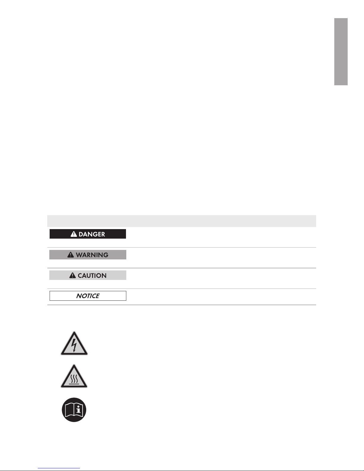
Symbol Description
DANGER indicates a hazardous situation which, if not avoided, will
result in death or serious injury.
WARNING indicates a hazardous situation which, if not avoided,
could result in death or serious injury.
CAUTION indicates a hazardous situation which, if not avoided,
could result in minor or moderate injury.
NOTICE is used to address practices not related to personal injury.
Warnings on this Product
The following symbols are used as product markings with the following meanings.
Warning regarding dangerous voltage
The product works with high voltages. All work on the product must only be performed as described in the documentation of the product.
Beware of hot surface
The product can become hot during operation. Do not touch the product during
operation.
Observe the operating instructions
Read the documentation of the product before working on it. Follow all safety
precautions and instructions as described in the documentation.
ENGLISH

General Warnings
SMA Solar Technology America LLC
Installation ManualRSS-US-IA-xx-144
General Warnings
WARNING
All electrical installations must be carried out in accordance with the local electrical standards
and the National Electrical Code® ANSI/NFPA70 or the Canadian Electrical Code
®
CSAC22.1. This document does not replace and is not intended to replace any local, state,
provincial, federal or national laws, regulations or codes applicable to the installation and use of
the product, including without limitation applicable electrical safety codes. All installations must
conform with the laws, regulations, codes and standards applicable in the jurisdiction of
installation. SMA assumes no responsibility for the compliance or non-compliance with such laws
or codes in connection with the installation of the product.
The product contains no user-serviceable parts.
For all repair and maintenance, always return the unit to an authorized SMA Service Center.
Before installing or using the product, read all of the instructions, cautions, and warnings in this
manual.
Wiring of the product must be made by qualified personnel only.
ENGLISH

Table of Contents
SMA Solar Technology America LLC
Installation Manual RSS-US-IA-xx-14 5
Table of Contents
1 Information on this Document................................................. 7
1.1 Validity........................................................................................................................ 7
1.2 Target Group.............................................................................................................. 7
1.3 Symbols ...................................................................................................................... 7
1.4 Nomenclature............................................................................................................. 7
2 Safety ........................................................................................ 8
2.1 Intended Use .............................................................................................................. 8
2.2 Safety Information...................................................................................................... 9
3 Scope of Delivery..................................................................... 10
4 Product Description.................................................................. 11
4.1 Rapid Shutdown System............................................................................................ 11
5 Mounting................................................................................... 13
5.1 Requirements for Mounting ....................................................................................... 13
5.2 Mounting the Rapid Shutdown Box on a Mounting System................................... 14
5.3 Mounting the Rapid Shutdown Box with Mounting Brackets.................................. 16
5.4 Mounting the Rapid Shutdown Controller................................................................ 17
6 Electrical Connection................................................................ 18
6.1 Safety during Electrical Connection.......................................................................... 18
6.2 Overview of the Rapid Shutdown Box Connection Area........................................ 19
6.2.1 Exterior View ............................................................................... 19
6.2.2 Interior View ................................................................................ 20
6.3 Connecting the Equipment Grounding Conductor to the Rapid Shutdown Box.... 20
6.4 Connecting the Rapid Shutdown Box and Rapid Shutdown Controller Together . 22
6.5 Connecting Rapid Shutdown Boxes Together.......................................................... 27
6.6 Connecting the Strings to Rapid Shutdown Box ...................................................... 30
7 Commissioning the Rapid Shutdown System ........................ 34
8 Checking the Function of the Rapid Shutdown System......... 35
9 Operating the Rapid Shutdown Controller............................ 36
9.1 Triggering the Rapid Shutdown Function.................................................................. 36
9.2 Resetting the Rapid Shutdown Function.................................................................... 36
10 Decommissioning the Rapid Shutdown System .................... 37
ENGLISH

Table of Contents
SMA Solar Technology America LLC
Installation ManualRSS-US-IA-xx-146
11 Technical Data .......................................................................... 40
11.1 Rapid Shutdown Box................................................................................................. 40
11.2 Rapid Shutdown Controller....................................................................................... 40
12 Contact ...................................................................................... 42
13 Compliance Information.......................................................... 43
ENGLISH

1 Information on this Document
SMA Solar Technology America LLC
Installation Manual RSS-US-IA-xx-14 7
1 Information on this Document
1.1 Validity
This document is valid for the following device types:
• RSB-2S-US-10 (SMA Rapid Shutdown Box)
• RSC-1X-US-10 (SMA Rapid Shutdown Controller)
1.2 Target Group
The tasks described in this document must only be performed by qualified persons. Qualified
persons must have the following skills:
• Knowledge of how PV systems work and are operated
• Training in how to deal with the dangers and risks associated with installing and using
electrical devices and installations
• Training in the installation and commissioning of electrical devices and installations
• Knowledge of the applicable standards and directives
• Knowledge of and compliance with this document and all safety information
1.3 Symbols
Symbol Explanation
Information that is important for a specific topic or goal, but is not
safety-relevant
Indicates a requirement for meeting a specific goal
Desired result
A problem that might occur
1.4 Nomenclature
Complete designation Designation in this document
SMA Rapid Shutdown System Rapid Shutdown System, system, product
SMA Rapid Shutdown Box Rapid Shutdown Box
SMA Rapid Shutdown Controller Rapid Shutdown Controller
SMA Solar Technology America LLC SMA
SMA Solar Technology Canada Inc. SMA
ENGLISH

2 Safety
SMA Solar Technology America LLC
Installation ManualRSS-US-IA-xx-148
2 Safety
2.1 Intended Use
The Rapid Shutdown System consists of one or more Rapid Shutdown Boxes and one Rapid
Shutdown Controller. PV systems equipped with the Rapid Shutdown System satisfy the
requirements of UL1741, Second Edition 2015 and Canadian Electrical Code 2015. The Rapid
Shutdown Controller activates and deactivates the Rapid Shutdown System and signals the status
of the Rapid Shutdown System via the green and red LEDs. The Rapid Shutdown Box electrically
discharges the PV array conductors from the Rapid Shutdown Box to the inverter within ten seconds
of activation of the emergency switch on the Rapid Shutdown Controller to ≤30V. This is done by
the disconnection of the PV array on the input side of the RapidShutdownBox while the stored
leading energy of the inverters is discharged simultaneously. When the irradiation on the PV array
is sufficient and the voltages have been electrically discharged in accordance with specification, the
green LED on the Rapid Shutdown Controller glows green constantly. When none of the LEDs of the
Rapid Shutdown Controllers are glowing after actuating the emergency switch, either the irradiation
on the PV array is too low and, thus, the supply voltage of the Rapid Shutdown System insufficient
or the installation of the Rapid Shutdown System is faulty or the Rapid Shutdown Box is defective.
The product is certified for use in PV systems with the following SMA inverters:
• SB3000TL-US-22 / SB3800TL-US-22 / SB4000TL-US-22 / SB5000TL-US-22 / SB6000TLUS-22 / SB7000TL-US-22 / SB7700TL-US-22
• SB3.0-1SP-US-40 / SB3.8-1SP-US-40 / SB5.0-1SP-US-40 / SB6.0-1SP-US-40 / SB7.0-1SPUS-40 / SB7.7-1SP-US-40
Use of the product in PV systems with inverters of manufacturers other than SMA is not permitted.
A maximum of 16 Rapid Shutdown Boxes can be operated in a Rapid Shutdown System.
The product is suitable for indoor and outdoor use.
All components must remain within their permitted operating ranges and their installation
requirements at all times.
The product is approved for the US and Canadian market.
Use this product only in accordance with the information provided in the enclosed documentation
and with the locally applicable standards and directives. Any other application may cause
personal injury or property damage.
Alterations to the product, e.g. changes or modifications, are only permitted with the express written
permission of SMA. Unauthorized alterations will void guarantee and warranty claims and in most
cases terminate the operating license. SMA shall not be held liable for any damage caused by
such changes.
Any use of the product other than that described in the Intended Use section does not qualify as the
intended use.
The enclosed documentation is an integral part of this product. Keep the documentation in a
convenient place for future reference and observe all instructions contained therein.
The type label must remain permanently attached to the product.
ENGLISH

2 Safety
SMA Solar Technology America LLC
Installation Manual RSS-US-IA-xx-14 9
2.2 Safety Information
This section contains safety information that must be observed at all times when working on or with
the product.
To prevent personal injury and property damage and to ensure long-term operation of the product,
read this section carefully and observe all safety information at all times.
DANGER
Danger to life due to high voltages of the PV array
When exposed to sunlight, the PV array generates dangerous DC voltage which is present in the
DC conductors. Touching the DC conductors can lead to lethal electric shocks.
• Disconnect the DC connectors on the input strings.
• Have the product mounted, installed and commissioned only by qualified persons with the
appropriate skills.
• Only touch the DC cables on their insulation.
• Do not touch the DC conductors.
DANGER
Danger to life due to electric shock in case of a ground fault
If a ground fault occurs, parts of the system may still be live. Touching live components can lead
to lethal electric shocks.
• Ensure that no voltage is present and wait five minutes before touching any parts of the PV
system or of the Rapid Shutdown System.
ENGLISH

3 Scope of Delivery
SMA Solar Technology America LLC
Installation ManualRSS-US-IA-xx-1410
3 Scope of Delivery
Check the scope of delivery for completeness and any externally visible damage. Contact your
distributor if the scope of delivery is incomplete or damaged.
Figure 1 : Components included in the scope of delivery
Position Quantity Designation
A 1 Rapid Shutdown Box
B 3 Spring lock washer
C 2 Clamping bracket
D 3 Washer
E 1 Hex nut
F 2 Cylindrical screw
G 1 Clamping bracket
H 3 Sealing plug for positive MC4 connector
I 3 Sealing plug for negative MC4 connector
K 3 Five-pole plug
L 2 Silicone tube (500mm (20in))
M 1 Cable tie
N 1 Rapid Shutdown Controller, adapter and key*
O 1 Installation manual
* Delivered in separate packaging
ENGLISH

4 Product Description
SMA Solar Technology America LLC
Installation Manual RSS-US-IA-xx-14 11
4 Product Description
4.1 Rapid Shutdown System
The Rapid Shutdown System consists of one or more Rapid Shutdown Boxes and one Rapid
Shutdown Controller. PV systems equipped with the Rapid Shutdown System satisfy the
requirements of UL1741, Second Edition 2015 and Canadian Electrical Code 2015. The Rapid
Shutdown Controller activates and deactivates the Rapid Shutdown System and signals the status
of the Rapid Shutdown System via the green and red LEDs. The Rapid Shutdown Box electrically
discharges the PV array conductors from the Rapid Shutdown Box to the inverter within ten seconds
of activation of the emergency switch on the Rapid Shutdown Controller to ≤30V. This is done by
the disconnection of the PV array on the input side of the RapidShutdownBox while the stored
leading energy of the inverters is discharged simultaneously. When the irradiation on the PV array
is sufficient and the voltages have been electrically discharged in accordance with specification, the
green LED on the Rapid Shutdown Controller glows green constantly. When none of the LEDs of the
Rapid Shutdown Controllers are glowing after actuating the emergency switch, either the irradiation
on the PV array is too low and, thus, the supply voltage of the Rapid Shutdown System insufficient
or the installation of the Rapid Shutdown System is faulty or the Rapid Shutdown Box is defective.
A D
E
1 ... 16
B
C
Figure 2 : Schematic diagram of a Rapid Shutdown system
Position Designation
A Rapid Shutdown Controller
B PV modules
C Rapid Shutdown Box
D Inverter
E Utility grid
ENGLISH

4 Product Description
SMA Solar Technology America LLC
Installation ManualRSS-US-IA-xx-1412
Design of the Rapid Shutdown Box and Rapid Shutdown Controller
Figure 3 : Design of the Rapid Shutdown Box and Rapid Shutdown Controller
Position Designation
A DC connection for the input strings
B Rapid Shutdown Box type label
C Rapid Shutdown Controller type label
D Rapid Shutdown Controller emergency switch
E Rapid Shutdown Controller green LED
F Rapid Shutdown Controller red LED
ENGLISH

5 Mounting
SMA Solar Technology America LLC
Installation Manual RSS-US-IA-xx-14 13
5 Mounting
5.1 Requirements for Mounting
Requirements for the mounting location:
WARNING
Danger to life due to fire or explosion
Despite careful construction, electrical devices can cause fires.
• Do not mount the Rapid Shutdown Box or Rapid Shutdown Controller in areas containing
highly flammable materials or gases.
• Do not mount the Rapid Shutdown Box or Rapid Shutdown Controller in areas exposed to
explosion hazards.
☐ The Rapid Shutdown Controller must be mounted in such a way that it is visible and freely
accessible to first responders.
☐ The mounting location of the Rapid Shutdown Controller must be suitable for the weight and
dimensions of the Rapid Shutdown Controller.
☐ The Rapid Shutdown Box can be mounted on the mounting system of the PV array, directly on
the roof or on a wall. Here, there must be a distance of at least 13mm (0.5in) between the
Rapid Shutdown Box and the module backsheet and the permissible cable length between the
PV array and the Rapid Shutdown Box must be observed.
☐ The mounting location of the Rapid Shutdown Box must be suitable for the weight and
dimensions of the Rapid Shutdown Box (see Section11 "Technical Data", page40).
☐ The specified ambient conditions at the mounting location of the Rapid Shutdown Box and
Rapid Shutdown Controller must be observed (see Section11 "Technical Data", page40).
Permissible cable lengths:
☐ The maximum cable length of 50m (164ft) from the Rapid Shutdown Box to the Rapid
Shutdown Controller must be observed.
☐ The maximum cable length of 100m (328ft) from the first Rapid Shutdown Box to the last
Rapid Shutdown Box in the system must be observed.
☐ Observe the maximum cable length between the PV array and Rapid Shutdown Box as
specified in the National Electrical Code® ANSI/NFPA 70 or the Canadian Electrical Code
®
CSA C22.1.
ENGLISH

5 Mounting
SMA Solar Technology America LLC
Installation ManualRSS-US-IA-xx-1414
Dimensions for mounting the Rapid Shutdown Box:
Figure 4 : Position of the anchoring points of the Rapid Shutdown Box
Permitted and prohibited mounting positions:
☐ The Rapid Shutdown Box and Rapid Shutdown Controller may only be mounted in a
permissible position. This ensures that moisture can not penetrate the Rapid Shutdown Box or
Rapid Shutdown Controller.
Figure 5 : Permitted and prohibited mounting positions
5.2 Mounting the Rapid Shutdown Box on a Mounting
System
There are several ways of attaching the Rapid Shutdown Box to the mounting system of the PV
array. In the following example, mounting with T-head bolts is described.
ENGLISH

5 Mounting
SMA Solar Technology America LLC
Installation Manual RSS-US-IA-xx-14 15
WARNING
Risk of falling when working on the roof
There is a risk of falling or slipping when working on the rooftop. Observe the applicable
accident prevention regulations for work on rooftops.
• Before stepping on the rooftop, ensure the load bearing capacity of all parts subjected to
load.
• In accordance with the accident prevention regulations, a safety harness must be worn or a
safety scaffold must be used.
• Use fall protection.
NOTICE
Damage to the PV module due to screws being too long
The length of the screws must be suitable for the distance between the Rapid Shutdown Box and
the underside of the PV module.
• Make sure that the PV module will not be damaged by the screws being used.
Additionally required mounting material (not included in the scope of delivery):
☐ The required fastening material must be selected according to the mounting system used.
☐ The mounting material must be made of stainless steel.
☐ Diameter of the screws: maximum 8 mm (0.3 in)
Procedure:
1. Insert the T-head bolts into the mounting system and turn by 90°. This will firmly anchor the
screws in the rack rail.
2. Place the Rapid Shutdown Box onto the anchored
screws. Here, insert the screws into the oblong holes
up to the desired fastening point.
ENGLISH

5 Mounting
SMA Solar Technology America LLC
Installation ManualRSS-US-IA-xx-1416
3. Attach the Rapid Shutdown Box using suitable
washers and nuts.
4. Ensure that the Rapid Shutdown Box is securely attached.
5.3 Mounting the Rapid Shutdown Box with Mounting
Brackets
If you would like to mount the Rapid Shutdown Box on the wall or directly on the roof, proceed as
described in the following.
Additionally required mounting material (not included in the scope of delivery):
☐ The mounting material must be made of stainless steel.
☐ 4 screws suitable for the support surface (diameter: 8mm (0.3in))
☐ 4 washers suitable for the screws (outer diameter: 16mm (0.6in))
☐ Where necessary, 4 screw anchors suitable for the support surface and the screws
Procedure:
1.
CAUTION
Risk of injury due to damaged cables
There may be power cables or other supply lines (e.g. gas or water) routed in the wall.
• Ensure that no lines are laid in the wall which could be damaged when drilling holes.
2. Align the Rapid Shutdown Box horizontally and mark the positions of the drill holes through
the mounting brackets.
3. Place the Rapid Shutdown Box to one side and drill the drill holes at the positions marked.
4. Insert screw anchors into the drill holes if the support surface requires them.
ENGLISH

5 Mounting
SMA Solar Technology America LLC
Installation Manual RSS-US-IA-xx-14 17
5. Align the Rapid Shutdown box over the drill holes
and attach it using suitable screws and washers.
5.4 Mounting the Rapid Shutdown Controller
Additionally required mounting material (not included in the scope of delivery):
☐ 4 screws suitable for the support surface (diameter: 4mm (0.16in))
☐ Where necessary, 4 screw anchors suitable for the support surface and the screws
Procedure:
1.
CAUTION
Risk of injury due to damaged cables
There may be power cables or other supply lines (e.g. gas or water) routed in the wall.
• Ensure that no lines are laid in the wall which could be damaged when drilling holes.
2. Unscrew the 4 screws in the upper enclosure part of
the Rapid Shutdown Controller using a cross-head
screwdriver (PZ2), remove the upper enclosure part
and place to one side.
3. Mark the positions of the drill holes using the 4 screw holes in the lower enclosure part of the
Rapid Shutdown Controller as a guide (see the rear side of the Rapid Shutdown Controller for
hole distances).
4. Place the Rapid Shutdown Controller to one side and drill the drill holes at the positions
marked.
5. Insert screw anchors into the drill holes if the support surface requires them.
6. Screw the lower enclosure part of the Rapid Shutdown Controller to the wall using the screws.
ENGLISH

6 Electrical Connection
SMA Solar Technology America LLC
Installation ManualRSS-US-IA-xx-1418
6 Electrical Connection
6.1 Safety during Electrical Connection
NOTICE
Damage to the Rapid Shutdown Box from moisture and dust ingress.
Dust and moisture ingress can damage the Rapid Shutdown Box and impair its functionality.
• Do not open the Rapid Shutdown Box during rain, snow or high levels of humidity (>95%).
• Only use listed rain-tight or liquid-tight conduit fittings to attach the conduits to the enclosure.
SMA recommends using conduit fittings with flat, pliable, thick rubber sealing gaskets. The
sealings should be roughly 2.54mm (0.1in / 7/64in) in thickness. SMA recommends
against using thinner, harder sealings (typically yellow or green colored). These sealing
types may not make reliable seals for this application. These sealings are approximately
1.9mm (0.075in / 5/64in) thick or less. SMA recommends against and does not accept
using conduit fittings with round cross section and o-ring type sealings as these types of
seals are not reliable for this application.
• Seal all unused openings tightly.
Electrical installations
All electrical installations must be carried out in accordance with the local standards and the
National Electrical Code® ANSI/NFPA 70 or the Canadian Electrical Code® CSA C22.1.
• The electrical connection of the Rapid Shutdown System may only be made by qualified
persons with appropriate skills.
• Ensure that no cables used for electrical connection are damaged.
The Rapid Shutdown function is only available if strings are correctly
connected at the inverter.
The Rapid Shutdown Box controls only strings which are connected to a Rapid Shutdown Box.
The Rapid Shutdown function is not available if the strings from a RapidShutdownBox are
connected in parallel with any string not connected to a RapidShutdownBox.
• Do not connect any output strings of various RapidShutdownBoxes in parallel to a single
input of an inverter or to another parallel connection point.
• The output strings of the RapidShutdownBox must not be connected in parallel.
• Always connect the output strings of the RapidShutdownBox to the same inverter. The
output strings must not be connected to various inverters.
ENGLISH

6 Electrical Connection
SMA Solar Technology America LLC
Installation Manual RSS-US-IA-xx-14 19
6.2 Overview of the Rapid Shutdown Box Connection
Area
6.2.1 Exterior View
+
+
+
+
A
D
E
B
C
Figure 6 : Exterior view of the Rapid Shutdown Box
Position Designation
A DC connection for the input strings 1 and 2, channel A
B DC connection for the input strings 3 and 4, channel B
C Connection point for the equipment grounding conductor
D Enclosure opening for the Rapid Shutdown Controller conductors and where
necessary for the conductors of an additional Rapid Shutdown Box (for conduits of trade size 16mm (0.5in))
E Enclosure opening for maximum 2 output strings* and where necessary for
the conductors of the Rapid Shutdown Controller (for conduits of the trade
size 21mm (0.75in))
* The input strings 1 and 2 (channel A) as well as 3 and 4 (channel B) are connected in parallel inside
the Rapid Shutdown Box.
ENGLISH

6 Electrical Connection
SMA Solar Technology America LLC
Installation ManualRSS-US-IA-xx-1420
6.2.2 Interior View
Figure 7 : Connection area inside the Rapid Shutdown Box
Position Designation
A Terminal block for the connection of the first output string, channel A
B Equipment Ground Bar
C Terminal block for the connection of the Rapid Shutdown Controller and/or
for the connection of an additional Rapid Shutdown Box
D Terminal block for the connection of the second output string, channel B
6.3 Connecting the Equipment Grounding Conductor to
the Rapid Shutdown Box
Each Rapid Shutdown Box can be grounded separately or several Rapid Shutdown Boxes can be
connected to one equipment grounding conductor. The required material for the connection of the
equipment grounding conductor are included in the scope of delivery.
Additionally required material (not included in the scope of delivery):
☐ Equipment grounding conductor
Equipment grounding conductor requirements:
☐ Conductor type: copper wire
☐ The conductor must be of solid wire.
☐ Conductor cross-section: 4mm² to 16mm² (12AWG to 6AWG)
ENGLISH

6 Electrical Connection
SMA Solar Technology America LLC
Installation Manual RSS-US-IA-xx-14 21
Procedure:
1. Place a washer onto the thread.
2. Position the equipment grounding conductor
horizontally below or above the thread.
3. Place the clamping bracket onto the thread and
over the equipment grounding conductor.
4. Place a spring lock washer and a hex nut onto the
thread and tighten the hex nut (torque:3.5Nm
(31in-lb)).
5.
NOTICE
Prevention of contact corrosion by bending the equipment grounding
conductor
The equipment grounding conductor should not be in contact with the Rapid Shutdown Box
enclosure. Contact may result in corrosion at the contact surface. Contact between fastening
screws and nuts is permitted.
• Bend the equipment grounding conductor in
such a way that it is not in contact with the
Rapid Shutdown Box enclosure.
ENGLISH

6 Electrical Connection
SMA Solar Technology America LLC
Installation ManualRSS-US-IA-xx-1422
6.4 Connecting the Rapid Shutdown Box and Rapid
Shutdown Controller Together
Additionally required material (not included in the scope of delivery):
☐ Conduit: either a separate conduit (trade size: 16mm (0.5in) or smaller with suitable reducer
bush) or use the conduit of the output strings to lay the conductors.
☐ If the conductors for the connection of the Rapid Shutdown Controller are to be laid in a
separate conduit: raintight or liquidtight conduit fitting (trade size: 16mm (0.5 in) or smaller
with suitable reducer bush).
☐ When laying a tray cable for exposed run (TC-ER): use cable gland which is suitable for the
cable and the enclosure opening.
Requirements for the conductors:
☐ When laying in outdoor areas without conduit, a tray cable for exposed run (TC-ER) must be
used.
☐ Conductor type: copper wire
☐ Number of conductors: 5
☐ If the conductors for the connection of the Rapid Shutdown Controller are laid in one conduit
together with the output strings, the conductors for the connection of the Rapid Shutdown
Controller must be insulated for the maximum PV system voltage.
☐ The conductors must be made of solid wire, stranded wire or fine stranded wire. When using
fine stranded wire, bootlace ferrules must be used.
☐ Conductor cross section: 0.75mm² to 1.5mm² (18AWG to 16AWG)
☐ Maximum length of the conductors from the Rapid Shutdown Box to the Rapid Shutdown
Controller: 50m (164ft)
Complying with the requirements for class 2 circuits
The circuit of the RapidShutdownController meets all requirements for class 2 circuits. The
maximum open-circuit voltage is 20V and maximum short-circuit current is 400mA.
Information on laying tray cables for exposed run (TC-ER)
The procedure for using conduits is described in this section. Instead of conduits, you can also
use tray cables for exposed run (TC-ER).
• When using tray cables for exposed run (TC-ER), select suitable cable glands and attach
to the enclosure opening instead of the conduit. When doing so, ensure that the
enclosure opening is sealed and no moisture can enter.
ENGLISH

6 Electrical Connection
SMA Solar Technology America LLC
Installation Manual RSS-US-IA-xx-14 23
Requirement:
☐ All electrical installations must be carried out in accordance with the locally applicable
electrical standards and the National Electrical Code® ANSI/NFPA 70 or the Canadian
Electrical Code® CSA C22.1.
Procedure:
If several Rapid Shutdown Boxes are present in your Rapid Shutdown System, connect the first
Rapid Shutdown Box to the Rapid Shutdown Controller first. To do so, first connect one end of the
conductors to the Rapid Shutdown Box and then connect the other end of the conductors to the
Rapid Shutdown Controller.
• Connect the conductors to the Rapid Shutdown Box.
• Connect the conductors to the Rapid Shutdown Controller.
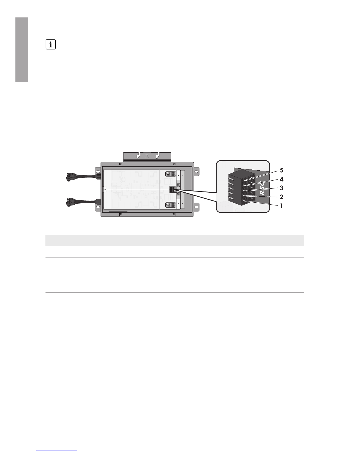
Connecting the conductors to the Rapid Shutdown Box
Figure 8 : Pin assignment of the lower pin row on the terminal block RSC in the Rapid Shutdown Box
Pin Assignment
1 Supply voltage (+12V)*
2 Rapid Shutdown Controller switch
3 Ground (0V)
4 Rapid Shutdown Controller green LED
5 Rapid Shutdown Controller red LED
* The open-circuit voltage may be up to 20V. The maximum short-circuit current is 400mA.
ENGLISH

6 Electrical Connection
SMA Solar Technology America LLC
Installation ManualRSS-US-IA-xx-1424
Procedure:
1. Unscrew the four screws of the Rapid Shutdown Box
enclosure lid using a hex socket screwdriver (TX25)
and remove the enclosure lid.
2. If the Rapid Shutdown Controller conductors are led into a separate conduit, remove the
sealing plug from one of the two enclosure openings with sealing plugs.
3. If the Rapid Shutdown Controller conductors are laid in the same conduit as the output strings,
pull off the adhesive tape on the enclosure opening.
4. Insert the conduit fitting into the opening on the Rapid Shutdown Box and tighten from the
inside using the counter nut.
5. Attach the conduit at the conduit fitting in the Rapid Shutdown Box enclosure.
6. Lead the conductors up to the terminal block RSC in the Rapid Shutdown Box.
7. Lead a silicone tube over the conductors inside the
Rapid Shutdown Box.
8. Strip off the conductor insulation by 8mm (0.31in).
9. In the case of fine stranded wire, provide each conductor with a bootlace ferrule.
10. Connect the conductors to a five-pole plug. Observe
the pin assignment.
11. Place the cable tie onto the silicone tube, tighten
and cut off the projecting end of the cable tie. This
connects the conductors and the silicone tube
together securely.
ENGLISH

6 Electrical Connection
SMA Solar Technology America LLC
Installation Manual RSS-US-IA-xx-14 25
12. Plug the five-pole plug with the connected
conductors into the lower pin row of the terminal
block RSC.
13. If there is only one Rapid Shutdown Box in the
system, plug the second five-pole plug into the upper
row of the terminal block RSC and place a jumper
wire between pins 3 and 4. Here, use a jumper wire
that is rated for the maximum system voltages or
insulate the jumper wire using a piece of one of the
supplied silicone tubes.
Connecting the conductors to the Rapid Shutdown Controller
+ A −
− B +
RSC
NC 1
2
X 12X
X 12X
NC 1
2
X 1
2
X
X 1
2
X
1
2
3
4
5
Figure 9 : Overview of the terminal blocks in the Rapid Shutdown Controller
Pin of the connecting
terminal plate in the
Rapid Shutdown
Box
Terminal in the
Rapid Shutdown
Controller
Assignment
1 X2 Supply voltage (+12V)*
2 2 Rapid Shutdown Controller switch
3 NC 1 Ground (0V)
4 X1 Rapid Shutdown Controller green LED
5 X1 Rapid Shutdown Controller red LED
* You can select on which terminal the connection is to be made, because a bridge must be placed
between the connections later.
ENGLISH

6 Electrical Connection
SMA Solar Technology America LLC
Installation ManualRSS-US-IA-xx-1426
Information on laying tray cables for exposed run (TC-ER)
The procedure for using conduits is described in this section. Instead of conduits, you can also
use tray cables for exposed run (TC-ER).
• When using tray cables for exposed run (TC-ER), select suitable cable glands and attach
to the enclosure opening instead of the conduit. When doing so, ensure that the
enclosure opening is sealed and no moisture can enter.
Procedure:
1. Break out the desired knockout on the Rapid
Shutdown Controller using a hammer and a
screwdriver When doing so, note that when using
the knockouts above and below in the lower
enclosure part, that the supplied adapter must be
used for conduits of the trade size 16mm (0.5in).
2. Where necessary, insert the supplied adapter in the position knocked out on the Rapid
Shutdown Controller and tighten from the inside using the counter nut.
3. Attach the conduit to the conduit fitting or onto the adapter in the Rapid Shutdown Controller
enclosure.
4. Lead the conductors up to the terminal blocks in the Rapid Shutdown Controller.
5. Strip off the conductor insulation by 8mm (0.31in).
6. In the case of fine stranded wire, provide each conductor with a bootlace ferrule.
7. Connect the conductors to the terminal blocks in
accordance with the assignment. To do so, insert
each conductor into the corresponding terminal and
tighten the screw on the terminal using a cross-head
screwdriver (PZ2).
8. Place a jumper wire between the terminal X2 of the green LED and terminal X2 of the red
LED.
9. Ensure that all terminals are allocated to the correct conductors.
10. Ensure that the conductors are plugged completely into the terminals up to their insulation.
Useful hint: To release the conductors from the terminals, the terminals must be opened. To do
so, loosen the screw on the terminal using a cross-head screwdriver (PZ2).
ENGLISH

6 Electrical Connection
SMA Solar Technology America LLC
Installation Manual RSS-US-IA-xx-14 27
11.
NOTICE
Damage to the Rapid Shutdown Controller due to moisture penetration
Moisture ingress can damage the Rapid Shutdown Controller and impair its functionality.
• Place the upper enclosure part onto the
lower enclosure part and tighten the four
screws using a cross-head screwdriver (PZ2)
(torque: 1.8Nm (16in-lb).
• Ensure that the screws with a torque of 1.8Nm (16in-lb) are tightened.
6.5 Connecting Rapid Shutdown Boxes Together
If several Rapid Shutdown Boxes are present in your Rapid Shutdown System, the Rapid Shutdown
Boxes must be connected together as described in the following. You can connect a maximum of
16 Rapid Shutdown Boxes together.
Additionally required material (not included in the scope of delivery):
☐ Conduit (trade size: 16mm (0.5in) or smaller with suitable reducer bush)
☐ Raintight or liquidtight conduit fitting (trade size: 16mm (0.5in) or smaller with suitable
reducer bush)
☐ When laying a tray cable for exposed run (TC-ER): cable gland suitable for the cable and the
enclosure opening.
Requirements for the conductors:
☐ When laying in outdoor areas without conduit, a tray cable for exposed run (TC-ER) must be
used.
☐ Conductor type: copper wire
☐ Number of conductors: 5
☐ The conductors must be made of solid wire, stranded wire or fine stranded wire. When using
fine stranded wire, bootlace ferrules must be used.
☐ Conductor cross section: 0.75mm² to 1.5mm² (18AWG to 16AWG)
☐ Maximum length of the conductors between two Rapid Shutdown Boxes: 50m (164ft)
☐ Maximum length of the conductors from the first Rapid Shutdown Box to the last Rapid
Shutdown Box: 100m (328ft)
ENGLISH
6 Electrical Connection
SMA Solar Technology America LLC
Installation ManualRSS-US-IA-xx-1428
Information on laying tray cables for exposed run (TC-ER)
The procedure for using conduits is described in this section. Instead of conduits, you can also
use tray cables for exposed run (TC-ER).
• When using tray cables for exposed run (TC-ER), select suitable cable glands and attach
to the enclosure opening instead of the conduit. When doing so, ensure that the
enclosure opening is sealed and no moisture can enter.
Requirement:
☐ All electrical installations must be carried out in accordance with the locally applicable
electrical standards and the National Electrical Code® ANSI/NFPA 70 or the Canadian
Electrical Code® CSA C22.1.
Pin assignment:
Figure 10 : Pin assignment of the upper pin row on the terminal block RSC in the Rapid Shutdown Box
Pin Assignment
1 Supply voltage (+12V)*
2 Rapid Shutdown Controller switch
3 Ground (0V)
4 Rapid Shutdown Controller green LED
5 Rapid Shutdown Controller red LED
* The open-circuit voltage may be up to 20°V.
Procedure:
1. Remove the sealing plug from one of the enclosure openings with sealing plugs.
2. Insert the conduit fitting into the opening of each Rapid Shutdown Box and tighten from the
inside using the counter nut.
3. Attach the conduit at the conduit fitting in each Rapid Shutdown Box enclosure.
4. Lead the conductors up to the terminal block RSC in the first Rapid Shutdown Box.
ENGLISH

6 Electrical Connection
SMA Solar Technology America LLC
Installation Manual RSS-US-IA-xx-14 29
5. Lead a silicone tube over the conductors inside the
Rapid Shutdown Box.
6. Strip off the conductor insulation by 8mm (0.31in).
7. In the case of fine stranded wire, provide each conductor with a bootlace ferrule.
8. Connect the conductors to a five-pole plug. Observe
the pin assignment.
9. Place the cable tie onto the silicone tube, tighten
and cut off the projecting end of the cable tie. This
connects the conductors and the silicone tube
together securely.
10. Plug the five-pole plug with the connected
conductors into the upper pin row of the terminal
block RSC.
11. Connect the Rapid Shutdown Boxes together. To do so, connect the incoming conductors to a
plug and plug this into the lower pin row of the connecting terminal block RSC, and always
connect the outgoing conductors to a plug and plug this into the upper pin row of the terminal
block RSC.
12. In the last Rapid Shutdown Box, plug the second
five-pole plug into the lower pin row of the terminal
block RSC and place a jumper wire between pins 3
and 4. Here, use a jumper wire that is rated for the
maximum system voltages or insulate the jumper
wire using a piece of one of the supplied silicone
tubes.
ENGLISH

6 Electrical Connection
SMA Solar Technology America LLC
Installation ManualRSS-US-IA-xx-1430
6.6 Connecting the Strings to Rapid Shutdown Box
Up to four input strings and two output strings can be connected to the Rapid Shutdown Box. In the
Rapid Shutdown Box, two of the four input strings are connected in parallel. The input strings must
be connected to the DC conductors fitted with MC4 connectors that lead from the Rapid Shutdown
Box. The output strings must be connected to the corresponding terminal blocks inside the Rapid
Shutdown Box.
Faulty operation of the inverter due to incorrect connection of the output
strings to the Rapid Shutdown Box
The output strings must lead to the same inverter if two output strings are connected to the
Rapid Shutdown Box. The operation of at least one inverter is interrupted if the two output
strings are connected to different inverters.
• Connect only output strings to the terminal block A and B which are leading to the same
inverter.
Procedure:
• Connect the output strings.
• Connect the input strings.
Connecting the Output Strings
Additionally required material:
☐ Conduit (trade size: 21mm (0.75in) or smaller with suitable reducer bush)
☐ Raintight or liquidtight conduit fitting (trade size: 21mm (0.75in) or smaller with suitable
reducer bush)
Requirements on・the conductors:
☐ Conductor type: copper wire
☐ The conductors must be made of solid wire, stranded wire or fine stranded wire. When using
fine stranded wire, bootlace ferrules must be used.
☐ Conductor cross-section: 4mm² to 10mm² (12AWG to 6AWG)
☐ The maximum permitted temperature for the terminal blocks for the connection of the output
strings of +90°C (+194°F) must be observed.
☐ The conductors with regards to its ampacity, rated temperatures, operating conditions and its
power loss must be made in accordance with the local standards and the National Electrical
Code® ANSI/NFPA 70 or the Canadian Electrical Code® CSA C22.1.
ENGLISH
 Loading...