

Page 1

RSS-US-IA-xx-14 | 101996-00.02 | Version 1.4
SMA RAPID SHUTDOWN SYSTEM
ENGLISH
Installation Manual
ESPAÑOL
Instrucciones de instalación
FRANÇAIS
Instructions d’installation
Page 2

Legal Provisions
SMA Solar Technology America LLC
Installation ManualRSS-US-IA-xx-142
Legal Provisions
No part of this document may be reproduced, stored in a retrieval system, or transmitted, in any
form or by any means, be it electronic, mechanical, photographic, magnetic or otherwise, without
the prior written permission of SMA Solar Technology America LLC.
Neither SMA Solar Technology AmericaLLC nor SMA Solar Technology Canada Inc. makes
representations, express or implied, with respect to this documentation or any of the equipment
and/or software it may describe, including (with no limitation) any implied warranties of utility,
merchantability, or fitness for any particular purpose. All such representations or warranties are
expressly disclaimed. Neither SMA Solar Technology AmericaLLC nor its distributors or dealers nor
SMA Solar Technology Canada Inc. nor its distributors or dealers shall be liable for any indirect,
incidental, or consequential damages under any circumstances.
The exclusion of implied warranties may not apply in all cases under some statutes, and thus the
above exclusion may not apply.
Specifications are subject to change without notice. Every attempt has been made to make this
document complete, accurate and up-to-date. Readers are cautioned, however, that product
improvements and field usage experience may cause SMA Solar Technology America LLC and/or
SMA Solar Technology Canada Inc. to make changes to these specifications without advance
notice, or per contract provisions in those cases where a supply agreement requires advance
notice. SMA shall not be responsible for any damages, including indirect, incidental or
consequential damages, caused by reliance on the material presented, including, but not limited to,
omissions, typographical errors, arithmetical errors or listing errors in the content material.
Trademarks
All trademarks are recognized, even if not explicitly identified as such. Missing designations do not
mean that a product or brand is not a registered trademark.
Modbus® is a registered trademark of SchneiderElectric and is licensed by the
ModbusOrganization,Inc.
QRCode is a registered trademark of DENSOWAVEINCORPORATED.
Phillips® and Pozidriv® are registered trademarks of PhillipsScrewCompany.
Torx® is a registered trademark of AcumentGlobalTechnologies,Inc.
SMASolar TechnologyAmerica LLC
6020 West Oaks Blvd.
Suite 300 Rocklin, CA 95765 U.S.A.
SMA Solar Technology Canada Inc.
2425 Matheson Blvd. E
7th Floor
Mississauga, ON L4W 5K4
Canada
Status: 8/29/2017
Copyright©2017SMA Solar Technology America LLC. All rights reserved.
ENGLISH
Page 3
Important Safety Instructions
SMA Solar Technology America LLC
Installation Manual RSS-US-IA-xx-14 3
Important Safety Instructions
SAVE THESE INSTRUCTIONS
This manual contains important instructions for the following products:
• RSB-2S-US-10 (SMA Rapid Shutdown Box)
• RSC-1X-US-10 (SMA Rapid Shutdown Controller)
This manual must be followed when using this product.
The product is designed and tested in accordance with international safety requirements, but as
with all electrical and electronic equipment, certain precautions must be observed when installing
and/or operating the product. To reduce the risk of personal injury and to ensure the safe
installation and operation of the product, you must carefully read and follow all instructions,
cautions and warnings in this manual.
Warnings in this Document
A warning describes a hazard to equipment or personnel. It calls attention to a procedure or
practice, which, if not correctly performed or adhered to, could result in damage to or destruction
of part or all of the SMA equipment and/or other equipment connected to the SMA equipment or
personal injury.
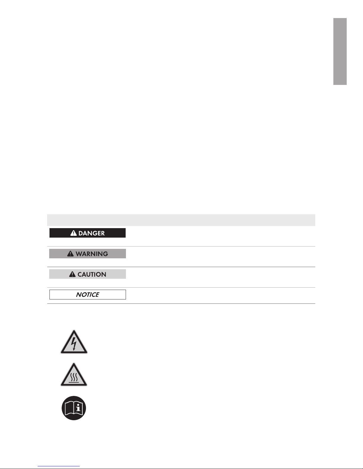
Symbol Description
DANGER indicates a hazardous situation which, if not avoided, will
result in death or serious injury.
WARNING indicates a hazardous situation which, if not avoided,
could result in death or serious injury.
CAUTION indicates a hazardous situation which, if not avoided,
could result in minor or moderate injury.
NOTICE is used to address practices not related to personal injury.
Warnings on this Product
The following symbols are used as product markings with the following meanings.
Warning regarding dangerous voltage
The product works with high voltages. All work on the product must only be performed as described in the documentation of the product.
Beware of hot surface
The product can become hot during operation. Do not touch the product during
operation.
Observe the operating instructions
Read the documentation of the product before working on it. Follow all safety
precautions and instructions as described in the documentation.
ENGLISH
Page 4

General Warnings
SMA Solar Technology America LLC
Installation ManualRSS-US-IA-xx-144
General Warnings
WARNING
All electrical installations must be carried out in accordance with the local electrical standards
and the National Electrical Code® ANSI/NFPA70 or the Canadian Electrical Code
®
CSAC22.1. This document does not replace and is not intended to replace any local, state,
provincial, federal or national laws, regulations or codes applicable to the installation and use of
the product, including without limitation applicable electrical safety codes. All installations must
conform with the laws, regulations, codes and standards applicable in the jurisdiction of
installation. SMA assumes no responsibility for the compliance or non-compliance with such laws
or codes in connection with the installation of the product.
The product contains no user-serviceable parts.
For all repair and maintenance, always return the unit to an authorized SMA Service Center.
Before installing or using the product, read all of the instructions, cautions, and warnings in this
manual.
Wiring of the product must be made by qualified personnel only.
ENGLISH
Page 5

Table of Contents
SMA Solar Technology America LLC
Installation Manual RSS-US-IA-xx-14 5
Table of Contents
1 Information on this Document................................................. 7
1.1 Validity........................................................................................................................ 7
1.2 Target Group.............................................................................................................. 7
1.3 Symbols ...................................................................................................................... 7
1.4 Nomenclature............................................................................................................. 7
2 Safety ........................................................................................ 8
2.1 Intended Use .............................................................................................................. 8
2.2 Safety Information...................................................................................................... 9
3 Scope of Delivery..................................................................... 10
4 Product Description.................................................................. 11
4.1 Rapid Shutdown System............................................................................................ 11
5 Mounting................................................................................... 13
5.1 Requirements for Mounting ....................................................................................... 13
5.2 Mounting the Rapid Shutdown Box on a Mounting System................................... 14
5.3 Mounting the Rapid Shutdown Box with Mounting Brackets.................................. 16
5.4 Mounting the Rapid Shutdown Controller................................................................ 17
6 Electrical Connection................................................................ 18
6.1 Safety during Electrical Connection.......................................................................... 18
6.2 Overview of the Rapid Shutdown Box Connection Area........................................ 19
6.2.1 Exterior View ............................................................................... 19
6.2.2 Interior View ................................................................................ 20
6.3 Connecting the Equipment Grounding Conductor to the Rapid Shutdown Box.... 20
6.4 Connecting the Rapid Shutdown Box and Rapid Shutdown Controller Together . 22
6.5 Connecting Rapid Shutdown Boxes Together.......................................................... 27
6.6 Connecting the Strings to Rapid Shutdown Box ...................................................... 30
7 Commissioning the Rapid Shutdown System ........................ 34
8 Checking the Function of the Rapid Shutdown System......... 35
9 Operating the Rapid Shutdown Controller............................ 36
9.1 Triggering the Rapid Shutdown Function.................................................................. 36
9.2 Resetting the Rapid Shutdown Function.................................................................... 36
10 Decommissioning the Rapid Shutdown System .................... 37
ENGLISH
Page 6

Table of Contents
SMA Solar Technology America LLC
Installation ManualRSS-US-IA-xx-146
11 Technical Data .......................................................................... 40
11.1 Rapid Shutdown Box................................................................................................. 40
11.2 Rapid Shutdown Controller....................................................................................... 40
12 Contact ...................................................................................... 42
13 Compliance Information.......................................................... 43
ENGLISH
Page 7

1 Information on this Document
SMA Solar Technology America LLC
Installation Manual RSS-US-IA-xx-14 7
1 Information on this Document
1.1 Validity
This document is valid for the following device types:
• RSB-2S-US-10 (SMA Rapid Shutdown Box)
• RSC-1X-US-10 (SMA Rapid Shutdown Controller)
1.2 Target Group
The tasks described in this document must only be performed by qualified persons. Qualified
persons must have the following skills:
• Knowledge of how PV systems work and are operated
• Training in how to deal with the dangers and risks associated with installing and using
electrical devices and installations
• Training in the installation and commissioning of electrical devices and installations
• Knowledge of the applicable standards and directives
• Knowledge of and compliance with this document and all safety information
1.3 Symbols
Symbol Explanation
Information that is important for a specific topic or goal, but is not
safety-relevant
Indicates a requirement for meeting a specific goal
Desired result
A problem that might occur
1.4 Nomenclature
Complete designation Designation in this document
SMA Rapid Shutdown System Rapid Shutdown System, system, product
SMA Rapid Shutdown Box Rapid Shutdown Box
SMA Rapid Shutdown Controller Rapid Shutdown Controller
SMA Solar Technology America LLC SMA
SMA Solar Technology Canada Inc. SMA
ENGLISH
Page 8

2 Safety
SMA Solar Technology America LLC
Installation ManualRSS-US-IA-xx-148
2 Safety
2.1 Intended Use
The Rapid Shutdown System consists of one or more Rapid Shutdown Boxes and one Rapid
Shutdown Controller. PV systems equipped with the Rapid Shutdown System satisfy the
requirements of UL1741, Second Edition 2015 and Canadian Electrical Code 2015. The Rapid
Shutdown Controller activates and deactivates the Rapid Shutdown System and signals the status
of the Rapid Shutdown System via the green and red LEDs. The Rapid Shutdown Box electrically
discharges the PV array conductors from the Rapid Shutdown Box to the inverter within ten seconds
of activation of the emergency switch on the Rapid Shutdown Controller to ≤30V. This is done by
the disconnection of the PV array on the input side of the RapidShutdownBox while the stored
leading energy of the inverters is discharged simultaneously. When the irradiation on the PV array
is sufficient and the voltages have been electrically discharged in accordance with specification, the
green LED on the Rapid Shutdown Controller glows green constantly. When none of the LEDs of the
Rapid Shutdown Controllers are glowing after actuating the emergency switch, either the irradiation
on the PV array is too low and, thus, the supply voltage of the Rapid Shutdown System insufficient
or the installation of the Rapid Shutdown System is faulty or the Rapid Shutdown Box is defective.
The product is certified for use in PV systems with the following SMA inverters:
• SB3000TL-US-22 / SB3800TL-US-22 / SB4000TL-US-22 / SB5000TL-US-22 / SB6000TLUS-22 / SB7000TL-US-22 / SB7700TL-US-22
• SB3.0-1SP-US-40 / SB3.8-1SP-US-40 / SB5.0-1SP-US-40 / SB6.0-1SP-US-40 / SB7.0-1SPUS-40 / SB7.7-1SP-US-40
Use of the product in PV systems with inverters of manufacturers other than SMA is not permitted.
A maximum of 16 Rapid Shutdown Boxes can be operated in a Rapid Shutdown System.
The product is suitable for indoor and outdoor use.
All components must remain within their permitted operating ranges and their installation
requirements at all times.
The product is approved for the US and Canadian market.
Use this product only in accordance with the information provided in the enclosed documentation
and with the locally applicable standards and directives. Any other application may cause
personal injury or property damage.
Alterations to the product, e.g. changes or modifications, are only permitted with the express written
permission of SMA. Unauthorized alterations will void guarantee and warranty claims and in most
cases terminate the operating license. SMA shall not be held liable for any damage caused by
such changes.
Any use of the product other than that described in the Intended Use section does not qualify as the
intended use.
The enclosed documentation is an integral part of this product. Keep the documentation in a
convenient place for future reference and observe all instructions contained therein.
The type label must remain permanently attached to the product.
ENGLISH
Page 9

2 Safety
SMA Solar Technology America LLC
Installation Manual RSS-US-IA-xx-14 9
2.2 Safety Information
This section contains safety information that must be observed at all times when working on or with
the product.
To prevent personal injury and property damage and to ensure long-term operation of the product,
read this section carefully and observe all safety information at all times.
DANGER
Danger to life due to high voltages of the PV array
When exposed to sunlight, the PV array generates dangerous DC voltage which is present in the
DC conductors. Touching the DC conductors can lead to lethal electric shocks.
• Disconnect the DC connectors on the input strings.
• Have the product mounted, installed and commissioned only by qualified persons with the
appropriate skills.
• Only touch the DC cables on their insulation.
• Do not touch the DC conductors.
DANGER
Danger to life due to electric shock in case of a ground fault
If a ground fault occurs, parts of the system may still be live. Touching live components can lead
to lethal electric shocks.
• Ensure that no voltage is present and wait five minutes before touching any parts of the PV
system or of the Rapid Shutdown System.
ENGLISH
Page 10

3 Scope of Delivery
SMA Solar Technology America LLC
Installation ManualRSS-US-IA-xx-1410
3 Scope of Delivery
Check the scope of delivery for completeness and any externally visible damage. Contact your
distributor if the scope of delivery is incomplete or damaged.
Figure 1 : Components included in the scope of delivery
Position Quantity Designation
A 1 Rapid Shutdown Box
B 3 Spring lock washer
C 2 Clamping bracket
D 3 Washer
E 1 Hex nut
F 2 Cylindrical screw
G 1 Clamping bracket
H 3 Sealing plug for positive MC4 connector
I 3 Sealing plug for negative MC4 connector
K 3 Five-pole plug
L 2 Silicone tube (500mm (20in))
M 1 Cable tie
N 1 Rapid Shutdown Controller, adapter and key*
O 1 Installation manual
* Delivered in separate packaging
ENGLISH
Page 11

4 Product Description
SMA Solar Technology America LLC
Installation Manual RSS-US-IA-xx-14 11
4 Product Description
4.1 Rapid Shutdown System
The Rapid Shutdown System consists of one or more Rapid Shutdown Boxes and one Rapid
Shutdown Controller. PV systems equipped with the Rapid Shutdown System satisfy the
requirements of UL1741, Second Edition 2015 and Canadian Electrical Code 2015. The Rapid
Shutdown Controller activates and deactivates the Rapid Shutdown System and signals the status
of the Rapid Shutdown System via the green and red LEDs. The Rapid Shutdown Box electrically
discharges the PV array conductors from the Rapid Shutdown Box to the inverter within ten seconds
of activation of the emergency switch on the Rapid Shutdown Controller to ≤30V. This is done by
the disconnection of the PV array on the input side of the RapidShutdownBox while the stored
leading energy of the inverters is discharged simultaneously. When the irradiation on the PV array
is sufficient and the voltages have been electrically discharged in accordance with specification, the
green LED on the Rapid Shutdown Controller glows green constantly. When none of the LEDs of the
Rapid Shutdown Controllers are glowing after actuating the emergency switch, either the irradiation
on the PV array is too low and, thus, the supply voltage of the Rapid Shutdown System insufficient
or the installation of the Rapid Shutdown System is faulty or the Rapid Shutdown Box is defective.
A D
E
1 ... 16
B
C
Figure 2 : Schematic diagram of a Rapid Shutdown system
Position Designation
A Rapid Shutdown Controller
B PV modules
C Rapid Shutdown Box
D Inverter
E Utility grid
ENGLISH
Page 12

4 Product Description
SMA Solar Technology America LLC
Installation ManualRSS-US-IA-xx-1412
Design of the Rapid Shutdown Box and Rapid Shutdown Controller
Figure 3 : Design of the Rapid Shutdown Box and Rapid Shutdown Controller
Position Designation
A DC connection for the input strings
B Rapid Shutdown Box type label
C Rapid Shutdown Controller type label
D Rapid Shutdown Controller emergency switch
E Rapid Shutdown Controller green LED
F Rapid Shutdown Controller red LED
ENGLISH
Page 13

5 Mounting
SMA Solar Technology America LLC
Installation Manual RSS-US-IA-xx-14 13
5 Mounting
5.1 Requirements for Mounting
Requirements for the mounting location:
WARNING
Danger to life due to fire or explosion
Despite careful construction, electrical devices can cause fires.
• Do not mount the Rapid Shutdown Box or Rapid Shutdown Controller in areas containing
highly flammable materials or gases.
• Do not mount the Rapid Shutdown Box or Rapid Shutdown Controller in areas exposed to
explosion hazards.
☐ The Rapid Shutdown Controller must be mounted in such a way that it is visible and freely
accessible to first responders.
☐ The mounting location of the Rapid Shutdown Controller must be suitable for the weight and
dimensions of the Rapid Shutdown Controller.
☐ The Rapid Shutdown Box can be mounted on the mounting system of the PV array, directly on
the roof or on a wall. Here, there must be a distance of at least 13mm (0.5in) between the
Rapid Shutdown Box and the module backsheet and the permissible cable length between the
PV array and the Rapid Shutdown Box must be observed.
☐ The mounting location of the Rapid Shutdown Box must be suitable for the weight and
dimensions of the Rapid Shutdown Box (see Section11 "Technical Data", page40).
☐ The specified ambient conditions at the mounting location of the Rapid Shutdown Box and
Rapid Shutdown Controller must be observed (see Section11 "Technical Data", page40).
Permissible cable lengths:
☐ The maximum cable length of 50m (164ft) from the Rapid Shutdown Box to the Rapid
Shutdown Controller must be observed.
☐ The maximum cable length of 100m (328ft) from the first Rapid Shutdown Box to the last
Rapid Shutdown Box in the system must be observed.
☐ Observe the maximum cable length between the PV array and Rapid Shutdown Box as
specified in the National Electrical Code® ANSI/NFPA 70 or the Canadian Electrical Code
®
CSA C22.1.
ENGLISH
Page 14

5 Mounting
SMA Solar Technology America LLC
Installation ManualRSS-US-IA-xx-1414
Dimensions for mounting the Rapid Shutdown Box:
Figure 4 : Position of the anchoring points of the Rapid Shutdown Box
Permitted and prohibited mounting positions:
☐ The Rapid Shutdown Box and Rapid Shutdown Controller may only be mounted in a
permissible position. This ensures that moisture can not penetrate the Rapid Shutdown Box or
Rapid Shutdown Controller.
Figure 5 : Permitted and prohibited mounting positions
5.2 Mounting the Rapid Shutdown Box on a Mounting
System
There are several ways of attaching the Rapid Shutdown Box to the mounting system of the PV
array. In the following example, mounting with T-head bolts is described.
ENGLISH
Page 15

5 Mounting
SMA Solar Technology America LLC
Installation Manual RSS-US-IA-xx-14 15
WARNING
Risk of falling when working on the roof
There is a risk of falling or slipping when working on the rooftop. Observe the applicable
accident prevention regulations for work on rooftops.
• Before stepping on the rooftop, ensure the load bearing capacity of all parts subjected to
load.
• In accordance with the accident prevention regulations, a safety harness must be worn or a
safety scaffold must be used.
• Use fall protection.
NOTICE
Damage to the PV module due to screws being too long
The length of the screws must be suitable for the distance between the Rapid Shutdown Box and
the underside of the PV module.
• Make sure that the PV module will not be damaged by the screws being used.
Additionally required mounting material (not included in the scope of delivery):
☐ The required fastening material must be selected according to the mounting system used.
☐ The mounting material must be made of stainless steel.
☐ Diameter of the screws: maximum 8 mm (0.3 in)
Procedure:
1. Insert the T-head bolts into the mounting system and turn by 90°. This will firmly anchor the
screws in the rack rail.
2. Place the Rapid Shutdown Box onto the anchored
screws. Here, insert the screws into the oblong holes
up to the desired fastening point.
ENGLISH
Page 16

5 Mounting
SMA Solar Technology America LLC
Installation ManualRSS-US-IA-xx-1416
3. Attach the Rapid Shutdown Box using suitable
washers and nuts.
4. Ensure that the Rapid Shutdown Box is securely attached.
5.3 Mounting the Rapid Shutdown Box with Mounting
Brackets
If you would like to mount the Rapid Shutdown Box on the wall or directly on the roof, proceed as
described in the following.
Additionally required mounting material (not included in the scope of delivery):
☐ The mounting material must be made of stainless steel.
☐ 4 screws suitable for the support surface (diameter: 8mm (0.3in))
☐ 4 washers suitable for the screws (outer diameter: 16mm (0.6in))
☐ Where necessary, 4 screw anchors suitable for the support surface and the screws
Procedure:
1.
CAUTION
Risk of injury due to damaged cables
There may be power cables or other supply lines (e.g. gas or water) routed in the wall.
• Ensure that no lines are laid in the wall which could be damaged when drilling holes.
2. Align the Rapid Shutdown Box horizontally and mark the positions of the drill holes through
the mounting brackets.
3. Place the Rapid Shutdown Box to one side and drill the drill holes at the positions marked.
4. Insert screw anchors into the drill holes if the support surface requires them.
ENGLISH
Page 17

5 Mounting
SMA Solar Technology America LLC
Installation Manual RSS-US-IA-xx-14 17
5. Align the Rapid Shutdown box over the drill holes
and attach it using suitable screws and washers.
5.4 Mounting the Rapid Shutdown Controller
Additionally required mounting material (not included in the scope of delivery):
☐ 4 screws suitable for the support surface (diameter: 4mm (0.16in))
☐ Where necessary, 4 screw anchors suitable for the support surface and the screws
Procedure:
1.
CAUTION
Risk of injury due to damaged cables
There may be power cables or other supply lines (e.g. gas or water) routed in the wall.
• Ensure that no lines are laid in the wall which could be damaged when drilling holes.
2. Unscrew the 4 screws in the upper enclosure part of
the Rapid Shutdown Controller using a cross-head
screwdriver (PZ2), remove the upper enclosure part
and place to one side.
3. Mark the positions of the drill holes using the 4 screw holes in the lower enclosure part of the
Rapid Shutdown Controller as a guide (see the rear side of the Rapid Shutdown Controller for
hole distances).
4. Place the Rapid Shutdown Controller to one side and drill the drill holes at the positions
marked.
5. Insert screw anchors into the drill holes if the support surface requires them.
6. Screw the lower enclosure part of the Rapid Shutdown Controller to the wall using the screws.
ENGLISH
Page 18

6 Electrical Connection
SMA Solar Technology America LLC
Installation ManualRSS-US-IA-xx-1418
6 Electrical Connection
6.1 Safety during Electrical Connection
NOTICE
Damage to the Rapid Shutdown Box from moisture and dust ingress.
Dust and moisture ingress can damage the Rapid Shutdown Box and impair its functionality.
• Do not open the Rapid Shutdown Box during rain, snow or high levels of humidity (>95%).
• Only use listed rain-tight or liquid-tight conduit fittings to attach the conduits to the enclosure.
SMA recommends using conduit fittings with flat, pliable, thick rubber sealing gaskets. The
sealings should be roughly 2.54mm (0.1in / 7/64in) in thickness. SMA recommends
against using thinner, harder sealings (typically yellow or green colored). These sealing
types may not make reliable seals for this application. These sealings are approximately
1.9mm (0.075in / 5/64in) thick or less. SMA recommends against and does not accept
using conduit fittings with round cross section and o-ring type sealings as these types of
seals are not reliable for this application.
• Seal all unused openings tightly.
Electrical installations
All electrical installations must be carried out in accordance with the local standards and the
National Electrical Code® ANSI/NFPA 70 or the Canadian Electrical Code® CSA C22.1.
• The electrical connection of the Rapid Shutdown System may only be made by qualified
persons with appropriate skills.
• Ensure that no cables used for electrical connection are damaged.
The Rapid Shutdown function is only available if strings are correctly
connected at the inverter.
The Rapid Shutdown Box controls only strings which are connected to a Rapid Shutdown Box.
The Rapid Shutdown function is not available if the strings from a RapidShutdownBox are
connected in parallel with any string not connected to a RapidShutdownBox.
• Do not connect any output strings of various RapidShutdownBoxes in parallel to a single
input of an inverter or to another parallel connection point.
• The output strings of the RapidShutdownBox must not be connected in parallel.
• Always connect the output strings of the RapidShutdownBox to the same inverter. The
output strings must not be connected to various inverters.
ENGLISH
Page 19

6 Electrical Connection
SMA Solar Technology America LLC
Installation Manual RSS-US-IA-xx-14 19
6.2 Overview of the Rapid Shutdown Box Connection
Area
6.2.1 Exterior View
+
+
+
+
A
D
E
B
C
Figure 6 : Exterior view of the Rapid Shutdown Box
Position Designation
A DC connection for the input strings 1 and 2, channel A
B DC connection for the input strings 3 and 4, channel B
C Connection point for the equipment grounding conductor
D Enclosure opening for the Rapid Shutdown Controller conductors and where
necessary for the conductors of an additional Rapid Shutdown Box (for conduits of trade size 16mm (0.5in))
E Enclosure opening for maximum 2 output strings* and where necessary for
the conductors of the Rapid Shutdown Controller (for conduits of the trade
size 21mm (0.75in))
* The input strings 1 and 2 (channel A) as well as 3 and 4 (channel B) are connected in parallel inside
the Rapid Shutdown Box.
ENGLISH
Page 20

6 Electrical Connection
SMA Solar Technology America LLC
Installation ManualRSS-US-IA-xx-1420
6.2.2 Interior View
Figure 7 : Connection area inside the Rapid Shutdown Box
Position Designation
A Terminal block for the connection of the first output string, channel A
B Equipment Ground Bar
C Terminal block for the connection of the Rapid Shutdown Controller and/or
for the connection of an additional Rapid Shutdown Box
D Terminal block for the connection of the second output string, channel B
6.3 Connecting the Equipment Grounding Conductor to
the Rapid Shutdown Box
Each Rapid Shutdown Box can be grounded separately or several Rapid Shutdown Boxes can be
connected to one equipment grounding conductor. The required material for the connection of the
equipment grounding conductor are included in the scope of delivery.
Additionally required material (not included in the scope of delivery):
☐ Equipment grounding conductor
Equipment grounding conductor requirements:
☐ Conductor type: copper wire
☐ The conductor must be of solid wire.
☐ Conductor cross-section: 4mm² to 16mm² (12AWG to 6AWG)
ENGLISH
Page 21

6 Electrical Connection
SMA Solar Technology America LLC
Installation Manual RSS-US-IA-xx-14 21
Procedure:
1. Place a washer onto the thread.
2. Position the equipment grounding conductor
horizontally below or above the thread.
3. Place the clamping bracket onto the thread and
over the equipment grounding conductor.
4. Place a spring lock washer and a hex nut onto the
thread and tighten the hex nut (torque:3.5Nm
(31in-lb)).
5.
NOTICE
Prevention of contact corrosion by bending the equipment grounding
conductor
The equipment grounding conductor should not be in contact with the Rapid Shutdown Box
enclosure. Contact may result in corrosion at the contact surface. Contact between fastening
screws and nuts is permitted.
• Bend the equipment grounding conductor in
such a way that it is not in contact with the
Rapid Shutdown Box enclosure.
ENGLISH
Page 22

6 Electrical Connection
SMA Solar Technology America LLC
Installation ManualRSS-US-IA-xx-1422
6.4 Connecting the Rapid Shutdown Box and Rapid
Shutdown Controller Together
Additionally required material (not included in the scope of delivery):
☐ Conduit: either a separate conduit (trade size: 16mm (0.5in) or smaller with suitable reducer
bush) or use the conduit of the output strings to lay the conductors.
☐ If the conductors for the connection of the Rapid Shutdown Controller are to be laid in a
separate conduit: raintight or liquidtight conduit fitting (trade size: 16mm (0.5 in) or smaller
with suitable reducer bush).
☐ When laying a tray cable for exposed run (TC-ER): use cable gland which is suitable for the
cable and the enclosure opening.
Requirements for the conductors:
☐ When laying in outdoor areas without conduit, a tray cable for exposed run (TC-ER) must be
used.
☐ Conductor type: copper wire
☐ Number of conductors: 5
☐ If the conductors for the connection of the Rapid Shutdown Controller are laid in one conduit
together with the output strings, the conductors for the connection of the Rapid Shutdown
Controller must be insulated for the maximum PV system voltage.
☐ The conductors must be made of solid wire, stranded wire or fine stranded wire. When using
fine stranded wire, bootlace ferrules must be used.
☐ Conductor cross section: 0.75mm² to 1.5mm² (18AWG to 16AWG)
☐ Maximum length of the conductors from the Rapid Shutdown Box to the Rapid Shutdown
Controller: 50m (164ft)
Complying with the requirements for class 2 circuits
The circuit of the RapidShutdownController meets all requirements for class 2 circuits. The
maximum open-circuit voltage is 20V and maximum short-circuit current is 400mA.
Information on laying tray cables for exposed run (TC-ER)
The procedure for using conduits is described in this section. Instead of conduits, you can also
use tray cables for exposed run (TC-ER).
• When using tray cables for exposed run (TC-ER), select suitable cable glands and attach
to the enclosure opening instead of the conduit. When doing so, ensure that the
enclosure opening is sealed and no moisture can enter.
ENGLISH
Page 23

6 Electrical Connection
SMA Solar Technology America LLC
Installation Manual RSS-US-IA-xx-14 23
Requirement:
☐ All electrical installations must be carried out in accordance with the locally applicable
electrical standards and the National Electrical Code® ANSI/NFPA 70 or the Canadian
Electrical Code® CSA C22.1.
Procedure:
If several Rapid Shutdown Boxes are present in your Rapid Shutdown System, connect the first
Rapid Shutdown Box to the Rapid Shutdown Controller first. To do so, first connect one end of the
conductors to the Rapid Shutdown Box and then connect the other end of the conductors to the
Rapid Shutdown Controller.
• Connect the conductors to the Rapid Shutdown Box.
• Connect the conductors to the Rapid Shutdown Controller.
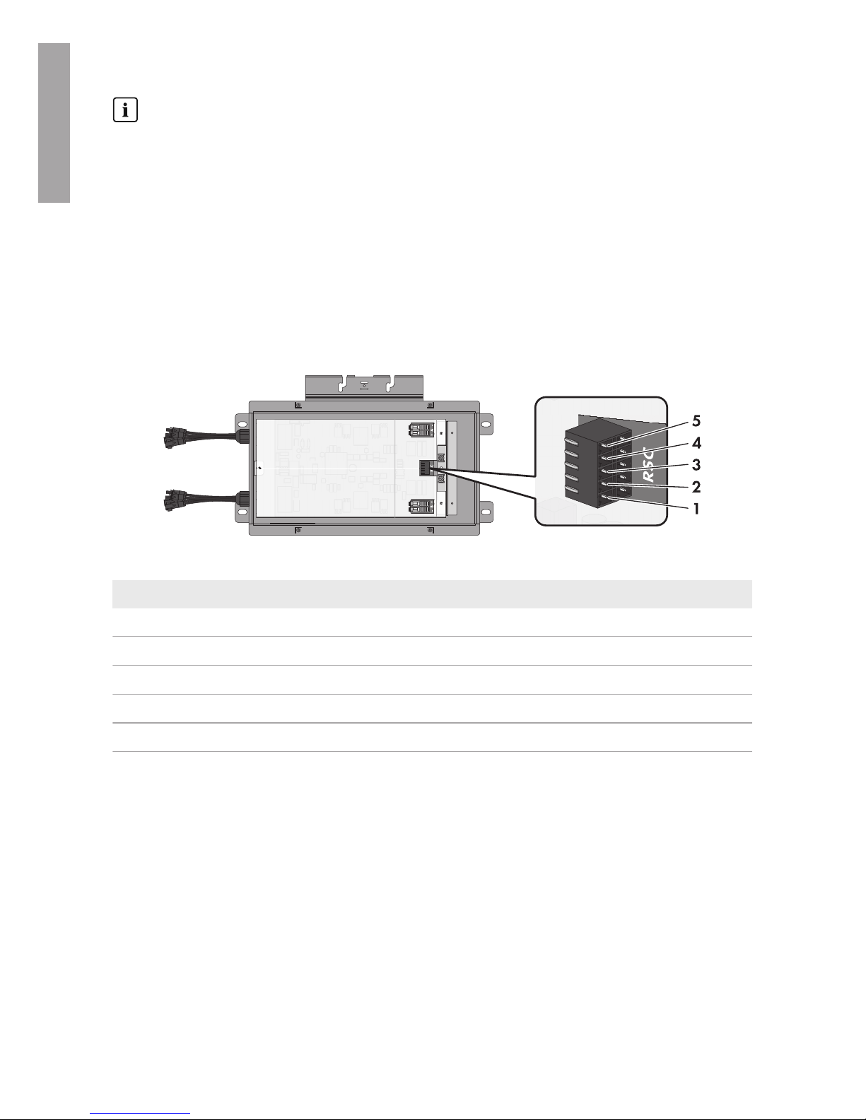
Connecting the conductors to the Rapid Shutdown Box
Figure 8 : Pin assignment of the lower pin row on the terminal block RSC in the Rapid Shutdown Box
Pin Assignment
1 Supply voltage (+12V)*
2 Rapid Shutdown Controller switch
3 Ground (0V)
4 Rapid Shutdown Controller green LED
5 Rapid Shutdown Controller red LED
* The open-circuit voltage may be up to 20V. The maximum short-circuit current is 400mA.
ENGLISH
Page 24

6 Electrical Connection
SMA Solar Technology America LLC
Installation ManualRSS-US-IA-xx-1424
Procedure:
1. Unscrew the four screws of the Rapid Shutdown Box
enclosure lid using a hex socket screwdriver (TX25)
and remove the enclosure lid.
2. If the Rapid Shutdown Controller conductors are led into a separate conduit, remove the
sealing plug from one of the two enclosure openings with sealing plugs.
3. If the Rapid Shutdown Controller conductors are laid in the same conduit as the output strings,
pull off the adhesive tape on the enclosure opening.
4. Insert the conduit fitting into the opening on the Rapid Shutdown Box and tighten from the
inside using the counter nut.
5. Attach the conduit at the conduit fitting in the Rapid Shutdown Box enclosure.
6. Lead the conductors up to the terminal block RSC in the Rapid Shutdown Box.
7. Lead a silicone tube over the conductors inside the
Rapid Shutdown Box.
8. Strip off the conductor insulation by 8mm (0.31in).
9. In the case of fine stranded wire, provide each conductor with a bootlace ferrule.
10. Connect the conductors to a five-pole plug. Observe
the pin assignment.
11. Place the cable tie onto the silicone tube, tighten
and cut off the projecting end of the cable tie. This
connects the conductors and the silicone tube
together securely.
ENGLISH
Page 25

6 Electrical Connection
SMA Solar Technology America LLC
Installation Manual RSS-US-IA-xx-14 25
12. Plug the five-pole plug with the connected
conductors into the lower pin row of the terminal
block RSC.
13. If there is only one Rapid Shutdown Box in the
system, plug the second five-pole plug into the upper
row of the terminal block RSC and place a jumper
wire between pins 3 and 4. Here, use a jumper wire
that is rated for the maximum system voltages or
insulate the jumper wire using a piece of one of the
supplied silicone tubes.
Connecting the conductors to the Rapid Shutdown Controller
+ A −
− B +
RSC
NC 1
2
X 12X
X 12X
NC 1
2
X 1
2
X
X 1
2
X
1
2
3
4
5
Figure 9 : Overview of the terminal blocks in the Rapid Shutdown Controller
Pin of the connecting
terminal plate in the
Rapid Shutdown
Box
Terminal in the
Rapid Shutdown
Controller
Assignment
1 X2 Supply voltage (+12V)*
2 2 Rapid Shutdown Controller switch
3 NC 1 Ground (0V)
4 X1 Rapid Shutdown Controller green LED
5 X1 Rapid Shutdown Controller red LED
* You can select on which terminal the connection is to be made, because a bridge must be placed
between the connections later.
ENGLISH
Page 26

6 Electrical Connection
SMA Solar Technology America LLC
Installation ManualRSS-US-IA-xx-1426
Information on laying tray cables for exposed run (TC-ER)
The procedure for using conduits is described in this section. Instead of conduits, you can also
use tray cables for exposed run (TC-ER).
• When using tray cables for exposed run (TC-ER), select suitable cable glands and attach
to the enclosure opening instead of the conduit. When doing so, ensure that the
enclosure opening is sealed and no moisture can enter.
Procedure:
1. Break out the desired knockout on the Rapid
Shutdown Controller using a hammer and a
screwdriver When doing so, note that when using
the knockouts above and below in the lower
enclosure part, that the supplied adapter must be
used for conduits of the trade size 16mm (0.5in).
2. Where necessary, insert the supplied adapter in the position knocked out on the Rapid
Shutdown Controller and tighten from the inside using the counter nut.
3. Attach the conduit to the conduit fitting or onto the adapter in the Rapid Shutdown Controller
enclosure.
4. Lead the conductors up to the terminal blocks in the Rapid Shutdown Controller.
5. Strip off the conductor insulation by 8mm (0.31in).
6. In the case of fine stranded wire, provide each conductor with a bootlace ferrule.
7. Connect the conductors to the terminal blocks in
accordance with the assignment. To do so, insert
each conductor into the corresponding terminal and
tighten the screw on the terminal using a cross-head
screwdriver (PZ2).
8. Place a jumper wire between the terminal X2 of the green LED and terminal X2 of the red
LED.
9. Ensure that all terminals are allocated to the correct conductors.
10. Ensure that the conductors are plugged completely into the terminals up to their insulation.
Useful hint: To release the conductors from the terminals, the terminals must be opened. To do
so, loosen the screw on the terminal using a cross-head screwdriver (PZ2).
ENGLISH
Page 27

6 Electrical Connection
SMA Solar Technology America LLC
Installation Manual RSS-US-IA-xx-14 27
11.
NOTICE
Damage to the Rapid Shutdown Controller due to moisture penetration
Moisture ingress can damage the Rapid Shutdown Controller and impair its functionality.
• Place the upper enclosure part onto the
lower enclosure part and tighten the four
screws using a cross-head screwdriver (PZ2)
(torque: 1.8Nm (16in-lb).
• Ensure that the screws with a torque of 1.8Nm (16in-lb) are tightened.
6.5 Connecting Rapid Shutdown Boxes Together
If several Rapid Shutdown Boxes are present in your Rapid Shutdown System, the Rapid Shutdown
Boxes must be connected together as described in the following. You can connect a maximum of
16 Rapid Shutdown Boxes together.
Additionally required material (not included in the scope of delivery):
☐ Conduit (trade size: 16mm (0.5in) or smaller with suitable reducer bush)
☐ Raintight or liquidtight conduit fitting (trade size: 16mm (0.5in) or smaller with suitable
reducer bush)
☐ When laying a tray cable for exposed run (TC-ER): cable gland suitable for the cable and the
enclosure opening.
Requirements for the conductors:
☐ When laying in outdoor areas without conduit, a tray cable for exposed run (TC-ER) must be
used.
☐ Conductor type: copper wire
☐ Number of conductors: 5
☐ The conductors must be made of solid wire, stranded wire or fine stranded wire. When using
fine stranded wire, bootlace ferrules must be used.
☐ Conductor cross section: 0.75mm² to 1.5mm² (18AWG to 16AWG)
☐ Maximum length of the conductors between two Rapid Shutdown Boxes: 50m (164ft)
☐ Maximum length of the conductors from the first Rapid Shutdown Box to the last Rapid
Shutdown Box: 100m (328ft)
ENGLISH
Page 28
6 Electrical Connection
SMA Solar Technology America LLC
Installation ManualRSS-US-IA-xx-1428
Information on laying tray cables for exposed run (TC-ER)
The procedure for using conduits is described in this section. Instead of conduits, you can also
use tray cables for exposed run (TC-ER).
• When using tray cables for exposed run (TC-ER), select suitable cable glands and attach
to the enclosure opening instead of the conduit. When doing so, ensure that the
enclosure opening is sealed and no moisture can enter.
Requirement:
☐ All electrical installations must be carried out in accordance with the locally applicable
electrical standards and the National Electrical Code® ANSI/NFPA 70 or the Canadian
Electrical Code® CSA C22.1.
Pin assignment:
Figure 10 : Pin assignment of the upper pin row on the terminal block RSC in the Rapid Shutdown Box
Pin Assignment
1 Supply voltage (+12V)*
2 Rapid Shutdown Controller switch
3 Ground (0V)
4 Rapid Shutdown Controller green LED
5 Rapid Shutdown Controller red LED
* The open-circuit voltage may be up to 20°V.
Procedure:
1. Remove the sealing plug from one of the enclosure openings with sealing plugs.
2. Insert the conduit fitting into the opening of each Rapid Shutdown Box and tighten from the
inside using the counter nut.
3. Attach the conduit at the conduit fitting in each Rapid Shutdown Box enclosure.
4. Lead the conductors up to the terminal block RSC in the first Rapid Shutdown Box.
ENGLISH
Page 29

6 Electrical Connection
SMA Solar Technology America LLC
Installation Manual RSS-US-IA-xx-14 29
5. Lead a silicone tube over the conductors inside the
Rapid Shutdown Box.
6. Strip off the conductor insulation by 8mm (0.31in).
7. In the case of fine stranded wire, provide each conductor with a bootlace ferrule.
8. Connect the conductors to a five-pole plug. Observe
the pin assignment.
9. Place the cable tie onto the silicone tube, tighten
and cut off the projecting end of the cable tie. This
connects the conductors and the silicone tube
together securely.
10. Plug the five-pole plug with the connected
conductors into the upper pin row of the terminal
block RSC.
11. Connect the Rapid Shutdown Boxes together. To do so, connect the incoming conductors to a
plug and plug this into the lower pin row of the connecting terminal block RSC, and always
connect the outgoing conductors to a plug and plug this into the upper pin row of the terminal
block RSC.
12. In the last Rapid Shutdown Box, plug the second
five-pole plug into the lower pin row of the terminal
block RSC and place a jumper wire between pins 3
and 4. Here, use a jumper wire that is rated for the
maximum system voltages or insulate the jumper
wire using a piece of one of the supplied silicone
tubes.
ENGLISH
Page 30

6 Electrical Connection
SMA Solar Technology America LLC
Installation ManualRSS-US-IA-xx-1430
6.6 Connecting the Strings to Rapid Shutdown Box
Up to four input strings and two output strings can be connected to the Rapid Shutdown Box. In the
Rapid Shutdown Box, two of the four input strings are connected in parallel. The input strings must
be connected to the DC conductors fitted with MC4 connectors that lead from the Rapid Shutdown
Box. The output strings must be connected to the corresponding terminal blocks inside the Rapid
Shutdown Box.
Faulty operation of the inverter due to incorrect connection of the output
strings to the Rapid Shutdown Box
The output strings must lead to the same inverter if two output strings are connected to the
Rapid Shutdown Box. The operation of at least one inverter is interrupted if the two output
strings are connected to different inverters.
• Connect only output strings to the terminal block A and B which are leading to the same
inverter.
Procedure:
• Connect the output strings.
• Connect the input strings.
Connecting the Output Strings
Additionally required material:
☐ Conduit (trade size: 21mm (0.75in) or smaller with suitable reducer bush)
☐ Raintight or liquidtight conduit fitting (trade size: 21mm (0.75in) or smaller with suitable
reducer bush)
Requirements on・the conductors:
☐ Conductor type: copper wire
☐ The conductors must be made of solid wire, stranded wire or fine stranded wire. When using
fine stranded wire, bootlace ferrules must be used.
☐ Conductor cross-section: 4mm² to 10mm² (12AWG to 6AWG)
☐ The maximum permitted temperature for the terminal blocks for the connection of the output
strings of +90°C (+194°F) must be observed.
☐ The conductors with regards to its ampacity, rated temperatures, operating conditions and its
power loss must be made in accordance with the local standards and the National Electrical
Code® ANSI/NFPA 70 or the Canadian Electrical Code® CSA C22.1.
ENGLISH
Page 31

6 Electrical Connection
SMA Solar Technology America LLC
Installation Manual RSS-US-IA-xx-14 31
Procedure:
1.
DANGER
Danger to life due to high voltages of the PV array
When exposed to sunlight, the PV array generates dangerous DC voltage which is present
in the DC conductors. Touching the DC conductors can lead to lethal electric shocks.
• Switch off the DC load-break switch on the inverter.
• Only touch the DC conductors on their insulation.
2. Pull off the adhesive tape on the enclosure opening.
3. Attach the conduit at the conduit fitting in the Rapid Shutdown Box enclosure.
4. Lead the positive and negative conductors of the first output string up to the terminal block A.
5. Lead the positive and negative conductors of the second output string up to the terminal block
B.
6. Lead the existing equipment grounding conductors of the output strings to the equipment
ground bar and connect them:
• Strip the insulation of the equipment grounding
conductor by 12mm (0.5in).
• Thread the cylinder-head screw through the spring lock washer, the clamping bracket and
the washer.
• Lead the equipment grounding conductor between the washer and the clamping bracket
and tighten the cylinder-head screw using a hex socket screwdriver (TX25) (torque: 6
Nm ± 0.6Nm (53in-lb ± 5in-lb)).
7. Strip the insulation from the conductors of each output string by 12mm (0.5in).
8. Connect the conductors of the first output string to
the terminal block A. To do so, push the locking
levers upwards to the stop and insert the conductors
into the terminals. When doing so, ensure that the
positive terminal and negative terminal have the
correct polarity at the inverter.
ENGLISH
Page 32

6 Electrical Connection
SMA Solar Technology America LLC
Installation ManualRSS-US-IA-xx-1432
9.
CAUTION
Danger of pinching fingers when the terminal block locking levers snap
shut
The locking levers close by snapping down fast and hard.
• Press the locking levers of the terminal block A down with your thumb only. When
doing so, ensure that your fingers can not be pinched when the locking levers snap
into place.
10. Connect the conductors of the second output strings
to the terminal block B. To do so, push the locking
levers upwards to the stop and insert the conductors
into the terminals. When doing so, ensure that the
positive terminal and negative terminal have the
correct polarity at the inverter.
11.
CAUTION
Danger of pinching fingers when the terminal block locking levers snap
shut
The locking levers close by snapping down fast and hard.
• Press the locking levers of the terminal block B down with your thumb only. When
doing so, ensure that your fingers can not be pinched when the locking levers snap
into place.
12. Ensure that all terminals are allocated to the correct conductors.
13. Hang the enclosure lid in the bracket of the upper
enclosure edge and tighten the four screws using a
hex socket screwdriver (TX25) (torque: 6Nm ±
0.6Nm (53in-lb ± 5in-lb)).
ENGLISH
Page 33

6 Electrical Connection
SMA Solar Technology America LLC
Installation Manual RSS-US-IA-xx-14 33
Connecting the Input Strings
Requirements:
☐ The two PV strings of each separate input are connected in parallel inside the Rapid Shutdown
Box. For the parallel connection of the input strings, a correct dimensioning of the strings must
be used.
☐ The maximum permitted system voltages of the Rapid Shutdown System may not be exceeded
(see Section11 "Technical Data", page40).
☐ Each positive DC conductor of a string must be equipped with a male MC4 connector (refer to
the connector manual for information on equipping).
☐ Each negative DC conductor of a string must be equipped with a female MC4 connector
(refer to the connector manual for information on equipping).
Procedure:
1.
DANGER
Danger to life due to high voltages
When exposed to sunlight, the PV array generates dangerous DC voltage which is present
in the DC conductors. Touching the DC conductors can lead to lethal electric shocks.
• Ensure that no voltage is present on the input strings.
• Ensure that the Rapid Shutdown Box is closed.
2. Connect the input strings to the MC4 connectors
that lead from the Rapid Shutdown Box. When
doing so, ensure that the the conductors are not
connected to the incorrect polarity. The negative DC
conductors to be connected must be equipped with
female MC4 connectors and the positive DC
conductors with male MC4 connectors.
_
_
+
+
+
_
+
_
☑ The connectors snap audibly into place.
3.
NOTICE
Damage to the MC4 connectors due to moisture ingress.
The MC4 connectors are only sealed if all MC4 connectors leading from the Rapid
Shutdown Box that are not required are sealed using the supplied sealing plugs.
• Plug the supplied sealing plugs into the MC4 connectors that are not required.
ENGLISH
Page 34

7 Commissioning the Rapid Shutdown System
SMA Solar Technology America LLC
Installation ManualRSS-US-IA-xx-1434
7 Commissioning the Rapid Shutdown System
1. Commission all inverters in the system (see inverter manual).
2. Check whether the inverter to which the strings of the Rapid Shutdown Box are connected
starts feed-in operation.
If the inverters display no errors and start feed-in operation, the Rapid Shutdown System is
connected correctly and automatically commissioned.
If the inverters do not start feed-in operation despite sufficient irradiation and display an error,
it is likely that an installation error is present. Ensure that the Rapid Shutdown System is
installed correctly.
3. If the Rapid Shutdown System has been commissioned, check the function of the Rapid
Shutdown System (see Section8, page35).
ENGLISH
Page 35

8 Checking the Function of the Rapid Shutdown System
SMA Solar Technology America LLC
Installation Manual RSS-US-IA-xx-14 35
8 Checking the Function of the Rapid Shutdown System
The Rapid Shutdown System is supplied via the PV array. If there is insufficient irradiation on the PV
array, the supply voltage of the Rapid Shutdown System is too low and the function of the Rapid
Shutdown System is not able to be checked.
Requirement:
☐ The Rapid Shutdown System must be commissioned.
☐ There must be sufficient irradiation on the PV array.
Procedure:
1. Press the emergency switch on the Rapid Shutdown Controller. This starts the automatic self-test
of the Rapid Shutdown Box and activates the Rapid Shutdown System.
☑ The red LED on the Rapid Shutdown Controller lights briefly or flashes. The Rapid
Shutdown Box reduces the voltage on the output string side. As soon as the voltage is
within the permitted range, the green LED on the Rapid Shutdown Controller glows
constantly.
☑ The green LED on the Rapid Shutdown Controller glows constantly. The Rapid Shutdown
System is active and the voltages on the output string side of the Rapid Shutdown Box are
≤30V.
✖ None of the LEDs on the Rapid Shutdown Controller are glowing?
Several causes are possible: Either the irradiation on the PV array is too low and, thus,
the supply voltage of the Rapid Shutdown System insufficient or the installation of the
Rapid Shutdown System is faulty or the Rapid Shutdown Box is defective.
• Make sure that the supply voltage of the Rapid Shutdown System is sufficient.
• Ensure that the Rapid Shutdown System is installed correctly.
• When the Rapid Shutdown System has enough supply voltage and is installed
correctly and still none of the LEDs are glowing, the Rapid Shutdown Box is faulty
and must be replaced. Contact the Service (see Section12 "Contact", page42).
✖ The red LED on the Rapid Shutdown Controller glows constantly?
The Rapid Shutdown Box is defective and the Rapid Shutdown System is not active.
• Contact the Service (see Section12 "Contact", page42).
2. Reset the Rapid Shutdown function (see Section9.2, page36).
ENGLISH
Page 36

9 Operating the Rapid Shutdown Controller
SMA Solar Technology America LLC
Installation ManualRSS-US-IA-xx-1436
9 Operating the Rapid Shutdown Controller
9.1 Triggering the Rapid Shutdown Function
• Press the emergency switch on the Rapid Shutdown Controller.
☑ The red LED on the Rapid Shutdown Controller lights briefly or flashes. The Rapid Shutdown
Box reduces the voltage on the output string side. As soon as the voltage is within the
permitted range, the green LED on the Rapid Shutdown Controller glows constantly.
☑ The green LED on the Rapid Shutdown Controller glows constantly. The Rapid Shutdown
System is active and the voltages on the output string side of the Rapid Shutdown Box are
≤30V.
✖ None of the LEDs on the Rapid Shutdown Controller are glowing?
Several causes are possible: Either the irradiation on the PV array is too low and, thus, the
supply voltage of the Rapid Shutdown System insufficient or the installation of the Rapid
Shutdown System is faulty or the Rapid Shutdown Box is defective.
• Make sure that the supply voltage of the Rapid Shutdown System is sufficient.
• Ensure that the Rapid Shutdown System is installed correctly.
• When the Rapid Shutdown System has enough supply voltage and is installed correctly
and still none of the LEDs are glowing, the Rapid Shutdown Box is faulty and must be
replaced. Contact the Service (see Section12 "Contact", page42).
✖ The red LED on the Rapid Shutdown Controller glows constantly?
The Rapid Shutdown Box is defective and the Rapid Shutdown System is not active.
• Contact the Service (see Section12 "Contact", page42).
9.2 Resetting the Rapid Shutdown Function
1. Ensure that the PV system can be reset to operating mode.
2. Insert the key into the keyhole of the emergency switch on the Rapid Shutdown Controller and
turn the key clockwise.
If the key for resetting the Rapid Shutdown Function is lost, contact the Service and request a
new key.
☑ The emergency switch returns to its starting position.
3. Remove the key from the keyhole and store safely in a location accessible to the PV system
operator.
ENGLISH
Page 37

10 Decommissioning the Rapid Shutdown System
SMA Solar Technology America LLC
Installation Manual RSS-US-IA-xx-14 37
10 Decommissioning the Rapid Shutdown System
Procedure:
1.
DANGER
Danger to life due to high voltages of the PV array
When exposed to sunlight, the PV array generates dangerous DC voltage which is present
in the DC conductors. Touching the DC conductors can lead to lethal electric shocks.
• Switch off the DC load-break switch on the inverter.
• Disconnect the DC connectors on the input strings.
• Only touch the DC conductors on their insulation.
2. Unscrew the four screws of the Rapid Shutdown Box
enclosure lid using a hex socket screwdriver (TX25)
and remove the enclosure lid.
3. Remove the conductors of the Rapid Shutdown Controllers and, if present, those of an
additional Rapid Shutdown Box, from the Rapid Shutdown Box. To do so, pull the respective
five-pole plugs with the connected conductors out of the terminal block RSC and remove from
the Rapid Shutdown Box.
4. Remove the output string conductors from the terminal blocks A and B. To do so, push the
locking levers upwards to the stop and pull the conductors out of the terminals.
5. Remove each output string equipment grounding conductor from the equipment ground bar.
To do this, unscrew the cylinder-head screw using a hex socket screwdriver (TX25) and
remove the cylinder-head screw, spring lock washer, the clamping bracket and the washer.
6. Remove the output string conductors and each equipment grounding conductor from the Rapid
Shutdown Box.
7. Remove the conduits and conduit fittings from the enclosure openings of the Rapid Shutdown
Box.
ENGLISH
Page 38

10 Decommissioning the Rapid Shutdown System
SMA Solar Technology America LLC
Installation ManualRSS-US-IA-xx-1438
8. Hang the enclosure lid in the bracket of the upper
enclosure edge and tighten the four screws using a
hex socket screwdriver (TX25) (torque: 6Nm ±
0.6Nm (53in-lb ± 5in-lb)).
9. Remove the equipment grounding conductor of the Rapid Shutdown Box. To do so, loosen the
hexagon nut using a wrench and remove the hexagon nut, the spring lock washer and the
clamping bracket from the grounding bolt.
10. Remove the Rapid Shutdown Box. To do this, depending on the mounting type, unscrew the
screws for attachment using a suitable screwdriver and remove the Rapid Shutdown Box from
the rack rail, from the wall or from the roof.
11. Unscrew the 4 screws in the upper enclosure part of
the Rapid Shutdown Controller using a cross-head
screwdriver (PZ2), remove the upper enclosure part
and place to one side.
12. Remove the conductors from the terminal blocks. To do so, loosen the screw of each terminal
using a cross-head screwdriver (PZ2) and pull the conductors out of the terminal.
13. Remove the conduits and conduit fittings or the adapter from the Rapid Shutdown Controller.
14. Remove the Rapid Shutdown Controller. To do this, unscrew the four screws for attachment
using a cross-head screwdriver (PZ2) and remove the Rapid Shutdown Controller from the
wall.
ENGLISH
Page 39

10 Decommissioning the Rapid Shutdown System
SMA Solar Technology America LLC
Installation Manual RSS-US-IA-xx-14 39
15. Place the upper enclosure part onto the lower
enclosure part and tighten the four screws using a
cross-head screwdriver (PZ2).
ENGLISH
Page 40

11 Technical Data
SMA Solar Technology America LLC
Installation ManualRSS-US-IA-xx-1440
11 Technical Data
11.1 Rapid Shutdown Box
Maximum input voltage 600V
Input voltage range 110V to 600V
Nominal current per channel 20A
Maximum input short-circuit current per channel 36A
Conductor type for the connection of the output
strings
Copper wire
Maximum permitted temperature for the terminal
blocks for the connection of the output strings
+90°C (+194°F)
Width x height x depth, without input strings
sticking out of the Rapid Shutdown Box
542mmx340mmx75mm
(21.3in x 13.4in x 3in)
Length x width x height of the packaging 770mmx395mmx125mm
(30.3in x 15.5in x 4.9in)
Weight of the Rapid Shutdown Box, without
packaging
3.8kg (8.4lb)
Weight of the Rapid Shutdown Box, including
packaging
5.5kg (12.1lb)
Operating temperature range -40°C to +75°C
(-40°F to +167°F)
Maximum permissible value for relative humidity, condensing
4% to 100%
Maximum operating altitude above mean sea
level (MSL)
3000m (9843ft)
Enclosure degree of protection according to
UL50
4X
Torque of the enclosure lid screws 6 Nm ± 0.6Nm (53in-lb ± 5in-lb)
11.2 Rapid Shutdown Controller
Width x height x depth, without input strings 80mmx153mmx104mm
(3.15in x 6.02in x 4.1in)
Weight, without packaging 328g (0.72lb)
Operating temperature range -25°Cto+70°C
(-13°F to +158°F)
ENGLISH
Page 41

11 Technical Data
SMA Solar Technology America LLC
Installation Manual RSS-US-IA-xx-14 41
Maximum operating altitude above mean sea
level (MSL)
3000m (9843ft)
Enclosure degree of protection according to
UL50
4X
Torque of the upper enclosure lid screws 1.8Nm (16in-lb)
ENGLISH
Page 42

12 Contact
SMA Solar Technology America LLC
Installation ManualRSS-US-IA-xx-1442
12 Contact
If you have technical problems with our products, please contact the SMAServiceLine. We require
the following information in order to provide you with the necessary assistance:
• Serial number of the Rapid Shutdown Box
• Serial number of the Rapid Shutdown Controller
United
States/ Estados Unidos
SMA Solar Technology
America LLC
Rocklin, CA
Toll free for USA, Canada and Puerto Rico / Llamada gratuita en EE. UU., Canadá y Puerto Rico:
+1877-MY-SMATech (+1877-697-6283)
International / Internacional: +1916625-0870
Canada/
Canadá
SMA Solar Technology
Canada Inc.
Mississauga
Toll free for Canada / gratuit pour le Canada:
+1877-MY-SMATech (+1877-697-6283)
ENGLISH
Page 43

13 Compliance Information
SMA Solar Technology America LLC
Installation Manual RSS-US-IA-xx-14 43
13 Compliance Information
FCC Compliance
This device complies with Part 15 of the FCC Rules.
Operation is subject to the following two conditions:
1. this device may not cause harmful interference, and
2. this device must accept any interference received, including interference that may cause
undesired operation.
NOTE: This equipment has been tested and found to comply with the limits for a Class B digital
device, pursuant to Part 15 of the FCC Rules. These limits are designed to provide reasonable
protection against harmful interference in a residential installation. This equipment generates, uses
and can radiate radio frequency energy and, if not installed and used in accordance with the
instructions, may cause harmful interference to radio communications. However, there is no
guarantee that interference will not occur in a particular installation. If this equipment does cause
harmful interference to radio or television reception, which can be determined by turning the
equipment off and on, the user is encouraged to try to correct the interference by one or more of
the following measures:
• Reorient or relocate the receiving antenna.
• Increase the separation between the equipment and receiver.
• Connect the equipment into an outlet on a circuit different from that to which the receiver is
connected.
• Consult the dealer or an experienced radio/TV technician for help.
Changes or modifications made to this equipment not expressly approved by SMA Solar
Technology America LLC may void the FCC authorization to operate this equipment.
IC Compliance
This Class B digital apparatus complies with Canadian ICES-003.
Cet appareil numérique de la classe B est conforme à la norme NMB-003 du Canada.
ENGLISH
Page 44

Disposiciones legales
SMA Solar Technology America LLC
Instrucciones de instalaciónRSS-US-IA-xx-1444
Disposiciones legales
Queda prohibida la reproducción total o parcial de este documento, así como su almacenamiento
en un sistema de recuperación y toda transmisión electrónica, mecánica, fotográfica, magnética o
de otra índole sin previa autorización por escrito de SMASolarTechnologyAmerica,LLC.
Ni SMASolarTechnologyAmerica,LLC ni SMASolarTechnologyCanadaInc. establecen
representaciones, ni expresas ni implícitas, con respecto a estas instrucciones o a cualquiera de los
equipos o softwares aquí descritos, incluyendo (sin limitación) cualquier garantía implícita en
cuanto a utilidad, mercantilidad o aptitud para cualquier propósito particular. Tales garantías
quedan expresamente denegadas. Ni SMASolarTechnologyAmerica,LLC ni sus distribuidores o
vendedores, ni SMASolarTechnologyCanadaInc. ni sus distribuidores o vendedores serán
responsables por ningún daño indirecto, incidental o resultante, bajo ninguna circunstancia.
La exclusión de garantías implícitas puede no ser aplicable en todos los casos.
Las especificaciones están sujetas a cambios sin previo aviso. Se ha tratado por todos los medios
de hacer que este documento sea completo y preciso y esté actualizado. Sin embargo, advertimos
a los lectores que SMASolarTechnologyAmerica,LLC y SMASolarTechnologyCanadaInc. se
reservan el derecho de cambiar estas especificaciones sin previo aviso o conforme con las
condiciones del existente contrato de entrega si lo consideran adecuado para optimizar el
producto y su uso. SMA no será responsable por ningún daño, ya sea indirecto, incidental o
resultante, como consecuencia de confiar en el material que se presenta, incluyendo, aunque no
exclusivamente, omisiones, errores tipográficos, aritméticos o de listado en el material del
contenido.
Marcas registradas
Se reconocen todas las marcas registradas, incluso si no están señaladas por separado. La falta
de señalización no implica que la mercancía o las marcas sean libres.
Modbus® es una marca registrada de SchneiderElectric y cuenta con licencia de la
ModbusOrganization,Inc.
QRCode es una marca registrada de DENSO WAVE INCORPORATED.
Phillips® y Pozidriv® son marcas registradas de PhillipsScrewCompany.
Torx® es una marca registrada de AcumentGlobalTechnologies,Inc.
SMASolar TechnologyAmerica LLC
6020 West Oaks Blvd.
Suite 300 Rocklin, CA 95765 U.S.A.
SMASolarTechnologyCanadaInc.
2425 Matheson Blvd. E
7th Floor
Mississauga, ON L4W 5K4
Canadá
Versión: 29/08/2017
Copyright©2017SMA Solar Technology America LLC. Reservados todos los derechos.
ESPAÑOL
Page 45

Instrucciones de seguridad importantes
SMA Solar Technology America LLC
Instrucciones de instalación RSS-US-IA-xx-14 45
Instrucciones de seguridad importantes
CONSERVAR INSTRUCCIONES
Estas instrucciones contienen información importante para estos productos:
• RSB-2S-US-10 (SMA Rapid Shutdown Box)
• RSC-1X-US-10 (SMA Rapid Shutdown Controller)
Las indicaciones de estas instrucciones deben cumplirse durante el manejo con el producto.
El producto ha sido diseñado y probado conforme a los requisitos internacionales de seguridad,
sin embargo, como en todos los equipos eléctricos o electrónicos, durante la instalación y el
funcionamiento deben tomarse determinadas medidas de precaución. Lea y cumpla todas las
indicaciones y advertencias de seguridad de estas instrucciones para minimizar el riesgo de
lesiones al usuario y garantizar una instalación y un funcionamiento seguros del producto.
Advertencias en este documento
Una advertencia describe un peligro que puede causar lesiones al usuario o daños materiales.
Llama la atención sobre un procedimiento o una actividad que, de no realizarse correctamente,
puede causar lesiones al usuario o daños materiales en productos de SMA o productos
conectados a estos.
Símbolo Descripción
PELIGRO representa una indicación de seguridad que, de no ser
observada, causa la muerte o lesiones físicas graves.
ADVERTENCIA representa una indicación de seguridad que, de no
ser observada, puede causar la muerte o lesiones físicas graves.
ATENCIÓN representa una indicación de seguridad que, de no ser
observada, puede causar lesiones físicas leves o de gravedad media.
PRECAUCIÓN representa una indicación de seguridad que, de no
ser observada, puede causar daños materiales.
Advertencias en este producto
Estos símbolos se usan como marcas del producto, con estos significados.
Advertencia de tensión peligrosa
El producto funciona con alta tensión. Todo trabajo que se realice en este producto debe llevarse a cabo únicamente como se describe en sus instrucciones.
Precaución con las superficies calientes
El producto se puede calentar durante el funcionamiento. No lo toque mientras
esté en marcha.
ESPAÑOL
Page 46

Instrucciones de seguridad importantes
SMA Solar Technology America LLC
Instrucciones de instalaciónRSS-US-IA-xx-1446
Observar las instrucciones de uso
Lea la documentación del producto antes de trabajar con él. Siga todas las
precauciones e instrucciones como se describen en la documentación.
ESPAÑOL
Page 47

Indicaciones generales
SMA Solar Technology America LLC
Instrucciones de instalación RSS-US-IA-xx-14 47
Indicaciones generales
ADVERTENCIA
Todas las instalaciones eléctricas deben realizarse conforme a la normativa local vigente y al
código National Electrical Code® ANSI/NFPA 70 o al Canadian Electrical Code® CSAC22.1.
Este documento no sustituye en ningún caso, ni tiene la pretensión de hacerlo, a cualquier
legislación, reglamento o norma regional, federal, provincial o estatal aplicables a la instalación
y el uso del producto; en especial, a las normas vigentes relativas a la seguridad eléctrica. La
instalación debe llevarse a cabo de conformidad con la legislación, las disposiciones, los
reglamentos y las normas vigentes en el lugar. SMA no asume responsabilidad alguna relativa
al cumplimiento o al incumplimiento de la legislación o las disposiciones relacionadas con la
instalación del producto.
El producto no contiene ningún componente sobre el que el usuario deba realizar labores de
mantenimiento.
Para realizar cualquier trabajo de reparación y mantenimiento, el equipo debe enviarse siempre
a un centro técnico aprobado por SMA.
Antes de la instalación y el manejo del producto, lea todas las indicaciones y advertencias de
estas instrucciones.
El cableado del producto solo puede llevarlo a cabo un especialista.
ESPAÑOL
Page 48

Índice
SMA Solar Technology America LLC
Instrucciones de instalaciónRSS-US-IA-xx-1448
Índice
1 Indicaciones sobre este documento ....................................... 50
1.1 Área de validez.......................................................................................................... 50
1.2 Grupo de destinatarios.............................................................................................. 50
1.3 Símbolos ..................................................................................................................... 50
1.4 Nomenclatura ............................................................................................................ 50
2 Seguridad ................................................................................. 51
2.1 Uso previsto................................................................................................................ 51
2.2 Indicaciones de seguridad ........................................................................................ 52
3 Contenido de la entrega.......................................................... 53
4 Descripción del producto......................................................... 54
4.1 Rapid Shutdown System............................................................................................ 54
5 Montaje..................................................................................... 56
5.1 Requisitos para el montaje ........................................................................................ 56
5.2 Montaje de la Rapid Shutdown Box con carril de perfil......................................... 57
5.3 Montaje de la Rapid Shutdown Box con bridas de sujeción.................................. 59
5.4 Montaje del Rapid Shutdown Controller.................................................................. 60
6 Conexión eléctrica.................................................................... 61
6.1 Seguridad en la conexión eléctrica.......................................................................... 61
6.2 Vista general de las áreas de conexión de la Rapid Shutdown Box..................... 62
6.2.1 Vista exterior................................................................................ 62
6.2.2 Vista interior................................................................................. 63
6.3 Conexión del conductor de puesta a tierra del equipo a la Rapid Shutdown
Box.............................................................................................................................. 63
6.4 Conexión entre sí de Rapid Shutdown Box y Rapid Shutdown Controller ............ 65
6.5 Conexión entre sí de las Rapid Shutdown Box........................................................ 70
6.6 Conexión de los strings a la Rapid Shutdown Box.................................................. 73
7 Puesta en marcha del Rapid Shutdown System.................... 77
8 Comprobación del correcto funcionamiento del Rapid
Shutdown System..................................................................... 78
9 Manejo del Rapid Shutdown Controller ................................ 79
9.1 Activación de la función Rapid Shutdown ............................................................... 79
9.2 Restablecimiento de la función Rapid Shutdown..................................................... 79
ESPAÑOL
Page 49

Índice
SMA Solar Technology America LLC
Instrucciones de instalación RSS-US-IA-xx-14 49
10 Puesta fuera de servicio del Rapid Shutdown System.......... 80
11 Datos técnicos........................................................................... 83
11.1 Rapid Shutdown Box................................................................................................. 83
11.2 Rapid Shutdown Controller....................................................................................... 83
12 Contacto.................................................................................... 85
13 Información de cumplimiento ................................................. 86
ESPAÑOL
Page 50

1 Indicaciones sobre este documento
SMA Solar Technology America LLC
Instrucciones de instalaciónRSS-US-IA-xx-1450
1 Indicaciones sobre este documento
1.1 Área de validez
Este documento es aplicable a estos modelos:
• RSB-2S-US-10 (SMA Rapid Shutdown Box)
• RSC-1X-US-10 (SMA Rapid Shutdown Controller)
1.2 Grupo de destinatarios
Las actividades descritas en este documento deben realizarlas exclusivamente especialistas que
han de contar con esta cualificación:
• Conocimientos sobre los procedimientos y el funcionamiento de plantas fotovoltaicas
• Formación sobre cómo actuar ante los peligros y riesgos relativos a la instalación y el manejo
de equipos eléctricos y plantas
• Formación profesional para la instalación y la puesta en marcha de equipos eléctricos y
plantas
• Conocimiento de las normativas y directivas aplicables
• Conocimiento y seguimiento de este documento y de todas sus indicaciones de seguridad
1.3 Símbolos
Símbolo Explicación
Información importante para un tema u objetivo concretos, aunque
no relevante para la seguridad
Requisito necesario para alcanzar un objetivo determinado
Resultado deseado
Posible problema
1.4 Nomenclatura
Denominación completa Denominación utilizada en este documento
SMA Rapid Shutdown System Rapid Shutdown System, sistema, producto
SMA Rapid Shutdown Box Rapid Shutdown Box
SMA Rapid Shutdown Controller Rapid Shutdown Controller
SMA Solar Technology America LLC SMA
SMA Solar Technology Canada Inc. SMA
ESPAÑOL
Page 51

2 Seguridad
SMA Solar Technology America LLC
Instrucciones de instalación RSS-US-IA-xx-14 51
2 Seguridad
2.1 Uso previsto
El Rapid Shutdown System se compone de una o varias Rapid Shutdown Box y un Rapid Shutdown
Controller. El Rapid Shutdown System cumple con los requisitos de la UL1741, Second Edition
2015, y del Canadian Electrical Code 2015 El Rapid Shutdown Controller sirve para activar y
desactivar el Rapid Shutdown System así como para señalizar el estado del Rapid Shutdown
System a través del led verde y rojo. La Rapid Shutdown Box sirve para descargar hasta ≤30 V los
conductores del generador fotovoltaico desde la Rapid Shutdown Box hasta el inversor en los
10segundos siguientes a la activación de la parada de emergencia en el Rapid Shutdown
Controller. Esto se realiza a través de la separación del generador fotovoltaico en el lado de
entrada de la Rapid Shutdown Box, al tiempo que se descarga la energía almacenada capacitiva
de los inversores. Una vez que la irradiación en el generador fotovoltaico es suficiente y las
tensiones se han descargado debidamente, el led verde del Rapid Shutdown Controller
permanece encendido. Si no se enciende ningún led del Rapid Shutdown Controller tras haber
pulsado la parada de emergencia, o la irradiación en el generador fotovoltaico es demasiado
baja y por esto la tensión de alimentación del Rapid Shutdown System no es suficiente o la
instalación del Rapid Shutdown System es incorrecta o la Rapid Shutdown Box está averiada.
El producto está autorizado para usarse en plantas fotovoltaicas con estos inversores de SMA:
• SB3000TL-US-22/SB3800TL-US-22/SB4000TL-US-22/SB5000TL-US-22/SB6000TLUS-22/SB7000TL-US-22/SB7700TL-US-22
• SB3.0-1SP-US-40 / SB3.8-1SP-US-40 / SB5.0-1SP-US-40 / SB6.0-1SP-US-40 / SB7.0-1SPUS-40 / SB7.7-1SP-US-40
No está permitido el uso del producto en plantas fotovoltaicas con inversores de fabricantes
distintos de SMA.
Un máximo de 16 Rapid Shutdown Box pueden ser utilizados en un Rapid Shutdown System.
El producto es apropiado para utilizarse en exteriores e interiores.
Deben respetarse en todo momento el rango de funcionamiento admisible y los requisitos de
instalación de todos los componentes.
El producto está autorizado para el mercado de EE.UU. y Canadá.
Utilice siempre el producto de acuerdo con las indicaciones de la documentación adjunta y
observe las normativas y directivas locales vigentes. Cualquier otro uso puede causarle lesiones al
usuario o daños materiales.
Para realizar cualquier intervención en el producto, como modificaciones o remodelaciones,
deberá contar con el permiso expreso y por escrito de SMA. Los cambios no autorizados
conllevan la pérdida de los derechos de garantía, así como la extinción de la autorización de
operación. Queda excluida la responsabilidad de SMA por los daños derivados de dichos
cambios.
Cualquier uso del producto distinto al descrito en el uso previsto se considerará inadecuado.
La documentación adjunta es parte integrante del producto. La documentación debe leerse,
observarse y guardarse en un lugar accesible en todo momento.
La placa de características debe estar en el producto en todo momento.
ESPAÑOL
Page 52

2 Seguridad
SMA Solar Technology America LLC
Instrucciones de instalaciónRSS-US-IA-xx-1452
2.2 Indicaciones de seguridad
Este capítulo contiene indicaciones de seguridad que deben observarse siempre en todos los
trabajos que se realizan en el producto y con el producto.
Para evitar daños personales y materiales y garantizar el funcionamiento permanente del
producto, lea detenidamente este capítulo y cumpla siempre las indicaciones de seguridad.
PELIGRO
Peligro de muerte por altas tensiones del generador fotovoltaico
Cuando recibe luz solar, el generador fotovoltaico produce una tensión de CC peligrosa que se
acopla a los conductores de CC. El contacto con dichos conductores de CC puede causar
descargas eléctricas mortales.
• Desconecte los conectadores de enchufe de CC de los strings de entrada.
• Encargue el montaje, la instalación y la puesta en marcha del producto únicamente a
especialistas con la cualificación adecuada.
• Agarre los cables de CC únicamente por el aislamiento.
• No toque los conductores de CC.
PELIGRO
Peligro de muerte por descarga eléctrica en caso de fallo a tierra
En caso de fallo a tierra los componentes de la planta pueden estar bajo tensión. El contacto
con los componentes conductores de tensión puede causar descargas eléctricas mortales.
• Compruebe que los componentes de la planta fotovoltaica o del Rapid Shutdown System
estén libres de tensión y espere 5minutos antes de tocarlos.
ESPAÑOL
Page 53

3 Contenido de la entrega
SMA Solar Technology America LLC
Instrucciones de instalación RSS-US-IA-xx-14 53
3 Contenido de la entrega
Compruebe que el contenido de la entrega esté completo y que no presente daños externos
visibles. En caso de que no esté completo o presente daños, póngase en contacto con su
distribuidor.
Imagen 1 : Componentes del contenido de la entrega
Posición Cantidad Denominación
A 1 Rapid Shutdown Box
B 3 Arandela elástica
C 2 Abrazadera
D 3 Arandela
E 1 Tuerca hexagonal
F 2 Tornillo cilíndrico
G 1 Abrazadera
H 3 Sellador para conectador de enchufe MC4 positivo
I 3 Sellador para conectador de enchufe MC4 negativo
K 3 Conector de cinco polos
L 2 Tubo de silicona (500mm [20in])
M 1 Abrazadera para cables
N 1 Rapid Shutdown Controller, adaptador y llave*
O 1 Instrucciones de instalación
* Se suministra embalado por separado.
ESPAÑOL
Page 54

4 Descripción del producto
SMA Solar Technology America LLC
Instrucciones de instalaciónRSS-US-IA-xx-1454
4 Descripción del producto
4.1 Rapid Shutdown System
El Rapid Shutdown System se compone de una o varias Rapid Shutdown Box y un Rapid Shutdown
Controller. El Rapid Shutdown System cumple con los requisitos de la UL1741, Second Edition
2015, y del Canadian Electrical Code 2015 El Rapid Shutdown Controller sirve para activar y
desactivar el Rapid Shutdown System así como para señalizar el estado del Rapid Shutdown
System a través del led verde y rojo. La Rapid Shutdown Box sirve para descargar hasta ≤30 V los
conductores del generador fotovoltaico desde la Rapid Shutdown Box hasta el inversor en los
10segundos siguientes a la activación de la parada de emergencia en el Rapid Shutdown
Controller. Esto se realiza a través de la separación del generador fotovoltaico en el lado de
entrada de la Rapid Shutdown Box, al tiempo que se descarga la energía almacenada capacitiva
de los inversores. Una vez que la irradiación en el generador fotovoltaico es suficiente y las
tensiones se han descargado debidamente, el led verde del Rapid Shutdown Controller
permanece encendido. Si no se enciende ningún led del Rapid Shutdown Controller tras haber
pulsado la parada de emergencia, o la irradiación en el generador fotovoltaico es demasiado
baja y por esto la tensión de alimentación del Rapid Shutdown System no es suficiente o la
instalación del Rapid Shutdown System es incorrecta o la Rapid Shutdown Box está averiada.
A D
E
1 ... 16
B
C
Imagen 2 : Representación esquemática de un Rapid Shutdown System
Posición Denominación
A Rapid Shutdown Controller
B Módulos fotovoltaicos
C Rapid Shutdown Box
D Inversor
E Red pública
ESPAÑOL
Page 55

4 Descripción del producto
SMA Solar Technology America LLC
Instrucciones de instalación RSS-US-IA-xx-14 55
Estructura de la Rapid Shutdown Box y del Rapid Shutdown Controller
Imagen 3 : Estructura de la Rapid Shutdown Box y del Rapid Shutdown Controller
Posición Denominación
A Conexión de CC de los strings de entrada
B Placa de características de la Rapid Shutdown Box
C Placa de características del Rapid Shutdown Controller
D Parada de emergencia del Rapid Shutdown Controller
E Led verde del Rapid Shutdown Controller
F Led rojo del Rapid Shutdown Controller
ESPAÑOL
Page 56

5 Montaje
SMA Solar Technology America LLC
Instrucciones de instalaciónRSS-US-IA-xx-1456
5 Montaje
5.1 Requisitos para el montaje
Requisitos del lugar de montaje:
ADVERTENCIA
Peligro de muerte por fuego o explosión
A pesar de estar cuidadosamente construidos, los equipos eléctricos pueden originar incendios.
• No instale la Rapid Shutdown Box ni el Rapid Shutdown Controller en áreas en las que se
encuentren materiales fácilmente inflamables o gases combustibles.
• No instale la Rapid Shutdown Box ni el Rapid Shutdown Controller en áreas
potencialmente explosivas.
☐ Monte el Rapid Shutdown Controller de forma que quede a la vista y sea accesible para los
encargados de primeros auxilios.
☐ El lugar de montaje del Rapid Shutdown Controller debe ser adecuado para el peso y las
dimensiones de este.
☐ La Rapid Shutdown Box puede montarse en el bastidor del generador fotovoltaico,
directamente sobre el tejado o en una pared. Para ello, entre la Rapid Shutdown Box y la
parte posterior del módulo debe respetarse una distancia mínima de 13mm (0,5in) y la
longitud de cable admisible entre el generador fotovoltaico y la Rapid Shutdown Box.
☐ El lugar de montaje de la Rapid Shutdown Box debe ser adecuado para el peso y las
dimensiones de esta (consulte el capítulo11 “Datos técnicos”, página83).
☐ Deben cumplirse las condiciones ambientales en el lugar de montaje de la Rapid Shutdown
Box y del Rapid Shutdown Controller (consulte el capítulo11 “Datos técnicos”, página83).
Longitudes de cable admisibles:
☐ Debe respetarse la longitud máxima del cable de 50m (164ft) entre la Rapid Shutdown Box
y el Rapid Shutdown Controller.
☐ Debe respetarse la longitud máxima del cable de 100m (328ft) entre la primera y la última
Rapid Shutdown Box del sistema.
☐ Respete la longitud máxima del cable entre el generador fotovoltaico y la Rapid Shutdown
Box conforme al National Electrical Code® ANSI/NFPA 70 o al Canadian Electrical Code
®
CSA C22.1.
ESPAÑOL
Page 57

5 Montaje
SMA Solar Technology America LLC
Instrucciones de instalación RSS-US-IA-xx-14 57
Dimensiones para el montaje de la Rapid Shutdown Box:
Imagen 4 : Posición de los puntos de fijación de la Rapid Shutdown Box
Posiciones de montaje permitidas y no permitidas:
☐ La Rapid Shutdown Box y el Rapid Shutdown Controller deben instalarse siempre en una
posición autorizada para garantizar que no entre humedad.
Imagen 5 : Posiciones de montaje permitidas y no permitidas
5.2 Montaje de la Rapid Shutdown Box con carril de perfil
Tiene varias opciones para fijar la Rapid Shutdown Box al bastidor del generador fotovoltaico. A
continuación se describe a modo de ejemplo el montaje con tornillos de cabeza de martillo.
ESPAÑOL
Page 58

5 Montaje
SMA Solar Technology America LLC
Instrucciones de instalaciónRSS-US-IA-xx-1458
ADVERTENCIA
Peligro de caída durante los trabajos en el tejado
Cuando se trabaja sobre un tejado existe el riesgo de que se produzcan caídas y resbalones.
Cuando vaya a trabajar en el tejado, tenga en cuenta la normativa de prevención de accidentes
vigentes.
• Antes de pisar el tejado, compruebe que todas las partes afectadas tienen una capacidad
de carga suficiente.
• De acuerdo con la normativa de prevención de accidentes deben utilizarse arneses de
seguridad para las personas o andamios.
• Utilice dispositivos de protección frente a caídas.
PRECAUCIÓN
Daño del módulo fotovoltaico por tornillo demasiado largo
La longitud del tornillo debe ser adecuada para la distancia entre la Rapid Shutdown Box y la
parte de abajo del módulo fotovoltaico.
• Asegúrese de que el módulo fotovoltaico no quede dañado por los tornillos utilizados.
Material de montaje adicional necesario (no incluido en el contenido de la entrega):
☐ El material de fijación necesario debe escogerse según el carril de perfil utilizado.
☐ El material de fijación debe ser de acero inoxidable.
☐ Diámetro de los tornillos: máximo 8 mm (0,3 in)
Procedimiento:
1. Introduzca los tornillos de cabeza de martillo en los carriles de perfil y gírelos 90°. Así los
tornillos se fijan en los carriles.
2. Coloque la Rapid Shutdown box en los tornillos
fijados. Para ello, guíe los tornillos por los agujeros
alargados hasta el punto de fijación deseado.
ESPAÑOL
Page 59

5 Montaje
SMA Solar Technology America LLC
Instrucciones de instalación RSS-US-IA-xx-14 59
3. Fije la Rapid Shutdown Box con las arandelas y
tuercas adecuadas.
4. Asegúrese de que la Rapid Shutdown Box esté bien fijada.
5.3 Montaje de la Rapid Shutdown Box con bridas de
sujeción
Si desea montar la Rapid Shutdown Box en la pared o directamente sobre el tejado, debe
proceder según se describe a continuación.
Material de montaje adicional necesario (no incluido en el contenido de la entrega):
☐ El material de fijación debe ser de acero inoxidable.
☐ Cuatro tornillos adecuados para la superficie (diámetro: 8mm [0,31in])
☐ Cuatro arandelas adecuadas para los tornillos (diámetro exterior: 16mm [0,6 in])
☐ En su caso, cuatro tacos adecuados para la superficie y los tornillos
Procedimiento:
1.
ATENCIÓN
Peligro de lesión por cables dañados
En la pared puede haber cables eléctricos u otras tuberías de suministro (por ejemplo, de
gas o de agua).
• Asegúrese de que no haya cables oempotrados en la pared que pueda dañar al
taladrar.
2. Coloque la Rapid Shutdown Box en horizontal y, con ayuda de las bridas de sujeción,
marque la posición de los agujeros que hay que perforar.
3. Deje a un lado la Rapid Shutdown Box y taladre los orificios marcados.
4. Según la superficie, inserte los tacos en los agujeros en caso necesario.
ESPAÑOL
Page 60

5 Montaje
SMA Solar Technology America LLC
Instrucciones de instalaciónRSS-US-IA-xx-1460
5. Coloque la Rapid Shutdown Box en los agujeros y
fíjela con los tornillos y las arandelas adecuados.
5.4 Montaje del Rapid Shutdown Controller
Material de montaje adicional necesario (no incluido en el contenido de la entrega):
☐ Cuatro tornillos adecuados para la superficie (diámetro: 4mm [0,16in])
☐ En su caso, cuatro tacos adecuados para la superficie y los tornillos
Procedimiento:
1.
ATENCIÓN
Peligro de lesión por cables dañados
En la pared puede haber cables eléctricos u otras tuberías de suministro (por ejemplo, de
gas o de agua).
• Asegúrese de que no haya cables oempotrados en la pared que pueda dañar al
taladrar.
2. Quite los cuatro tornillos de la parte superior de la
carcasa del Rapid Shutdown Controller con un
destornillador de estrella Pozidriv (PZ2), retire la
parte superior de la carcasa y déjela a un lado.
3. Marque la posición de los agujeros con ayuda de los cuatro orificios de la parte inferior de la
carcasa del Rapid Shutdown Controller (para las distancias entre los orificios, vea la parte
posterior del Rapid Shutdown Controller).
4. Deje a un lado el Rapid Shutdown Controller y taladre los orificios marcados.
5. Según la superficie, inserte los tacos en los agujeros en caso necesario.
6. Fije la parte inferior de la carcasa del Rapid Shutdown Controller a la pared con tornillos.
ESPAÑOL
Page 61

6 Conexión eléctrica
SMA Solar Technology America LLC
Instrucciones de instalación RSS-US-IA-xx-14 61
6 Conexión eléctrica
6.1 Seguridad en la conexión eléctrica
PRECAUCIÓN
Daños en la Rapid Shutdown Box debido a la infiltración de humedad y
polvo
Si penetra polvo o humedad en la Rapid Shutdown Box, esta podría resultar dañada y sus
funciones podrían verse limitadas.
• No abra la Rapid Shutdown Box si llueve o nieva o si la humedad del aire es elevada (>
95 %).
• Para fijar los conductos para cables a la carcasa utilice solamente manguitos con
certificación resistentes a la lluvia o humedad. SMA recomienda utilizar manguitos con
juntas de goma planas gruesas flexibles. Las juntas deben tener un grosor de unos
2,54mm (0,1in / 7/64in). SMA desaconseja el uso de juntas finas y duras (suelen ser de
color amarillo o verde), ya que para esta utilización este tipo de juntas por lo general no
ofrece un cierre estanco fiable. Estas juntas tienen un grosor aproximado de 1,9mm
(0,075in / 5/64in) o menos. SMA no recomienda ni acepta la utilización de manguitos
con sección redonda y de juntas tóricas, puesto que este tipo de junta no ofrece la
fiabilidad necesaria para esta aplicación.
• Cierre de manera estanca las aberturas que no utilice.
Instalaciones eléctricas
Todas las instalaciones eléctricas deben realizarse conforme a la normativa local vigente y al
código National Electrical Code® ANSI/NFPA 70 o al Canadian Electrical Code® CSA
C22.1.
• La conexión eléctrica del Rapid Shutdown System solo podrán llevarla a cabo
especialistas con la cualificación adecuada.
• Es necesario asegurarse de que los cables utilizados en la conexión eléctrica no estén
dañados.
La función del Rapid Shutdown solo está disponible si los strings están
correctamente conectados al inversor.
La Rapid Shutdown Box solo controla aquellos strings que estén conectados a través de una
Rapid Shutdown Box. El Rapid Shutdown no funciona si los strings de la Rapid Shutdown Box
se conectan en paralelo a los strings que no están conectados a través de una Rapid
Shutdown Box.
• No conecte strings de salida con diferentes Rapid Shutdown Box en paralelo a una
entrada única de un inversor u otro punto de conexión en paralelo.
• Los strings de salida de la Rapid Shutdown Box no se deben conectar en paralelo.
• Conectar los strings de salida de la Rapid Shutdown Box siempre en el mismo inversor.
Los strings de salida no se deben conectar a diferentes inversores.
ESPAÑOL
Page 62

6 Conexión eléctrica
SMA Solar Technology America LLC
Instrucciones de instalaciónRSS-US-IA-xx-1462
6.2 Vista general de las áreas de conexión de la Rapid
Shutdown Box
6.2.1 Vista exterior
+
+
+
+
A
D
E
B
C
Imagen 6 : Vista exterior de la Rapid Shutdown Box
Posición Denominación
A Conexión de CC de los strings de entrada 1 y 2, Channel A
B Conexión de CC de los strings de entrada 3 y 4, Channel B
C Punto de conexión para el conductor de puesta a tierra del equipo
D Abertura en la carcasa para los conductores del Rapid Shutdown Controller
y, en caso necesario, para los conductores de una Rapid Shutdown Box adicional (para conductos para cables del tamaño comercial 16mm [0,5in])
E Abertura en la carcasa para un máximo de dos strings de salida* y, en caso
necesario, para los conductores de la Rapid Shutdown Box (para conductos
para cables del tamaño comercial 21mm [0,75in])
* Los strings de entrada 1 y 2 (Channel A) así como 3 y 4 (Channel B) se conectan en paralelo dentro
de la Rapid Shutdown Box.
ESPAÑOL
Page 63

6 Conexión eléctrica
SMA Solar Technology America LLC
Instrucciones de instalación RSS-US-IA-xx-14 63
6.2.2 Vista interior
Imagen 7 : Áreas de conexión en el interior de la Rapid Shutdown Box
Posición Denominación
A Caja de bornes para conectar el primer string de salida, Channel A
B Barra de puesta a tierra del equipo
C Caja de bornes para conectar el Rapid Shutdown Controller y/o una Rapid
Shutdown Box adicional
D Caja de bornes para conectar el segundo string de salida, Channel B
6.3 Conexión del conductor de puesta a tierra del equipo
a la Rapid Shutdown Box
Puede poner a tierra cada Rapid Shutdown Box por separado o conectar varias Rapid Shutdown
Box con un conductor de puesta a tierra del equipo. El material necesario para la conexión del
conductor de puesta a tierra del equipo se incluye en el paquete de entrega.
Material adicional necesario (no incluido en el contenido de la entrega):
☐ Conductor de puesta a tierra del equipo
Requisitos del conductor de puesta a tierra del equipo:
☐ Tipo de conductor: alambre de cobre
☐ El conductor debe ser de cable macizo.
☐ Sección del conductor: 4mm²a16mm² (12AWGa6AWG)
ESPAÑOL
Page 64

6 Conexión eléctrica
SMA Solar Technology America LLC
Instrucciones de instalaciónRSS-US-IA-xx-1464
Procedimiento:
1. Coloque una arandela en la rosca.
2. Coloque el conductor de puesta a tierra del equipo
en horizontal por debajo o por encima de la rosca.
3. Coloque la abrazadera sobre la rosca y sobre el
conductor de puesta a tierra del equipo.
4. Coloque 1 arandela elástica y 1 tuerca hexagonal
sobre la rosca y apriete la tuerca hexagonal (par
de apriete:3,5Nm [31in-lb]).
5.
PRECAUCIÓN
Prevención de la corrosión por contacto si se curva el conductor de
puesta a tierra del equipo
El conductor de puesta a tierra del equipo no debe tocar la carcasa de la Rapid Shutdown
Box. En caso de contacto, puede producirse corrosión en la superficie. El contacto de los
tornillos de fijación y las tuercas es posible.
• Curve el conductor de puesta a tierra del
equipo de tal forma que no apoye en la
carcasa de la Rapid Shutdown Box.
ESPAÑOL
Page 65

6 Conexión eléctrica
SMA Solar Technology America LLC
Instrucciones de instalación RSS-US-IA-xx-14 65
6.4 Conexión entre sí de Rapid Shutdown Box y Rapid
Shutdown Controller
Material adicional necesario (no incluido en el contenido de la entrega):
☐ Conducto para cables: O bien tienda un conducto para cables propio (tamaño comercial: 16
mm [0,5 in] o inferior con reductores adecuados) o tienda los conductores conjuntamente en
el conducto para cables de los strings de salida.
☐ Si utiliza un conducto para cables propio para tender los conductores para la conexión del
Rapid Shutdown Controller: manguito resistente a la lluvia o humedad (tamaño comercial:
16mm [0,5 in] o inferior con reductores adecuados)
☐ Si tiende un Tray Cable for exposed run (TC-ER), emplee un racor atornillado para cables
adecuado para el cable y la abertura en la carcasa.
Requisitos de los conductores:
☐ En caso de tendido en exteriores sin conducto para cables, debe utilizarse un Tray Cable for
exposed run (TC-ER).
☐ Tipo de conductor: alambre de cobre
☐ Número de conductores: 5
☐ Si los conductores para la conexión del Rapid Shutdown Controller están tendidos en un
conducto para cables junto con los strings de salida, los conductores para la conexión del
Rapid Shutdown Controller deben estar aislados para la tensión maxima del sistema
fotovoltaico.
☐ Los cables deben ser de cable macizo, cordón o cordón fino. Si se usan cordones finos deben
utilizarse virolas.
☐ Sección del conductor: 0,75mm²a1,5mm² (18AWGa16AWG)
☐ Longitud máxima de los conductores entre la Rapid Shutdown Box y el Rapid Shutdown
Controller: 50m (164ft)
Cumplimiento con los requisitos de la clase 2 de conmutaciones
El circuito de detección del Rapid Shutdown Controllers cumple con los requisitos de la clase
2 de conmutaciones. La tensión en vacío máxima es de 20V y la corriente de cortocircuito
máxima es de 400mA.
Indicación para el tendido de Tray Cables for exposed run (TC-ER)
En este capítulo se describe si se utilizan conductos para cables. En lugar de conductos para
cables también pueden usarse Tray Cable for exposed run (TC-ER).
• Si utiliza Tray Cables for exposed run (TC-ER), seleccione racores atornillados para
cables adecuados y colóquelos en la abertura en la carcasa en lugar de los conductos
para cables. Asegúrese de que la abertura en la carcasa sea estanca y no entre
humedad.
ESPAÑOL
Page 66

6 Conexión eléctrica
SMA Solar Technology America LLC
Instrucciones de instalaciónRSS-US-IA-xx-1466
Requisito:
☐ Todas las instalaciones eléctricas deben realizarse conforme a la normativa local vigente y al
código National Electrical Code® ANSI/NFPA 70 o al Canadian Electrical Code
®
CSAC22.1.
Procedimiento:
Si su Rapid Shutdown System dispone de varias Rapid Shutdown Box, conecte solamente la
primera Rapid Shutdown Box con el Rapid Shutdown Controller. Para ello, conecte primero un
extremo de los conductores a la Rapid Shutdown Box y, a continuación, el otro extremo de los
conductores al Rapid Shutdown Controller.
• Conecte los conductores a la Rapid Shutdown Box.
• Conecte los conductores al Rapid Shutdown Controller.
Conexión de los conductores a la Rapid Shutdown Box
Imagen 8 : Asignación de patillas de la fila inferior de la caja de bornes RSC en la Rapid Shutdown Box
Patilla Asignación
1 Tensión de alimentación (+12V)*
2 Interruptor del Rapid Shutdown Controller
3 Masa (0V)
4 Led verde del Rapid Shutdown Controller
5 Led rojo del Rapid Shutdown Controller
* La tensión en vacío puede llegar hasta 20V. La corriente máxima de cortocircuito es de 400mA.
ESPAÑOL
Page 67

6 Conexión eléctrica
SMA Solar Technology America LLC
Instrucciones de instalación RSS-US-IA-xx-14 67
Procedimiento:
1. Suelte los cuatro tornillos de la tapa de la carcasa
de la Rapid Shutdown Box con un destornillador
hexagonal (TX25) y retire la tapa.
2. Si los conductores del Rapid Shutdown Controller están tendidos en un conducto para cables
propio, retire el sellador de una de las dos aberturas en la carcasa con selladores.
3. Si los conductores del Rapid Shutdown Controller se tienden en el mismo conducto para
cables que para los strings de salida, quite la cinta adhesiva de la abertura en la carcasa.
4. En la Rapid Shutdown Box, introduzca el manguito en la abertura y fíjelo desde el interior con
la contratuerca.
5. Fije el conducto para cables al manguito en la carcasa de la Rapid Shutdown Box.
6. Introduzca los conductores en la caja de bornes RSC de la Rapid Shutdown Box.
7. Dentro de la Rapid Shutdown Box, cubra los
conductores con un tubo de silicona.
8. Pele 8mm (0,31in) de los conductores.
9. En los cordones finos, remate los conductores con una virola.
10. Conecte los conductores a un conector de cinco
polos. Preste atención a la asignación de patillas.
11. Coloque una abrazadera para cables alrededor
del tubo de silicona, apriétela y corte el extremo
sobrante. De esta manera los conductores y el tubo
de silicona están unidos firmemente.
ESPAÑOL
Page 68

6 Conexión eléctrica
SMA Solar Technology America LLC
Instrucciones de instalaciónRSS-US-IA-xx-1468
12. Introduzca el conector de cinco polos con los
conductores conectados en la fila inferior de patillas
de la caja de bornes RSC.
13. Si el sistema solo dispone de una Rapid Shutdown
Box, introduzca el conector de cinco polos en la fila
superior de patillas de la caja de bornes RSC y
coloque una ligadura de alambre entre las patillas
3 y 4. Utilice una ligadura de alambre
dimensionada para las tensiones máximas del
sistema o aísle la ligadura de alambre con un trozo
de tubo de silicona de uno de los tubos
suministrados.
Conexión de los conductores al Rapid Shutdown Controller
+ A −
− B +
RSC
NC 1
2
X 12X
X 12X
NC 1
2
X 1
2
X
X 1
2
X
1
2
3
4
5
Imagen 9 : Vista rápida de las cajas de bornes del Rapid Shutdown Controller
Patilla de la caja de
bornes en la Rapid
Shutdown Box
Borne en el Rapid
Shutdown Controller
Asignación
1 X2 Tensión de alimentación (+12V)*
2 2 Interruptor del Rapid Shutdown Controller
3 NC 1 Masa (0V)
4 X1 Led verde del Rapid Shutdown Controller
5 X1 Led rojo del Rapid Shutdown Controller
* Puede elegir a qué borne desea realizar la conexión ya que posteriormente será necesario colocar un
puente entre las conexiones.
ESPAÑOL
Page 69

6 Conexión eléctrica
SMA Solar Technology America LLC
Instrucciones de instalación RSS-US-IA-xx-14 69
Indicación para el tendido de Tray Cables for exposed run (TC-ER)
En este capítulo se describe si se utilizan conductos para cables. En lugar de conductos para
cables también pueden usarse Tray Cable for exposed run (TC-ER).
• Si utiliza Tray Cables for exposed run (TC-ER), seleccione racores atornillados para
cables adecuados y colóquelos en la abertura en la carcasa en lugar de los conductos
para cables. Asegúrese de que la abertura en la carcasa sea estanca y no entre
humedad.
Procedimiento:
1. En el Rapid Shutdown Controller, rompa la posición
de rotura controlada deseada con un martillo y un
destornillador. Tenga en cuenta que para realizar
posiciones de rotura controlada arriba y abajo en
la parte inferior de la carcasa se debe utilizar el
adaptador suministrado para conductos para
cables del tamaño comercial 16mm (0,5in).
2. Dado el caso, coloque en el Rapid Shutdown Controller el adaptador suministrado en la
posición deseada y fíjelo desde el interior con la contratuerca.
3. Fije el conducto para cables al manguito o al adaptador en la carcasa del Rapid Shutdown
Controller.
4. Introduzca los conductores en las cajas de bornes del Rapid Shutdown Controller.
5. Pele 8mm (0,31in) de los conductores.
6. En los cordones finos, remate los conductores con una virola.
7. Conecte los conductores a las cajas de bornes en
función de la asignación. Para ello, introduzca los
conductores en el respectivo borne y apriete el
tornillo del borne con un destornillador de estrella
Pozidriv (PZ2).
8. Coloque una ligadura de alambre entre el borne X2 del led verde y el borne X2 del led rojo.
9. Asegúrese de que todos los bornes estén conectados con el conductor correcto.
10. Asegúrese de que los conductores estén totalmente metidos en los bornes, hasta el
aislamiento.
Consejo: Para soltar los conductores de los bornes, se deben abrir los bornes. Suelte el
tornillo del borne con un destornillador de estrella Pozidriv (PZ2).
ESPAÑOL
Page 70

6 Conexión eléctrica
SMA Solar Technology America LLC
Instrucciones de instalaciónRSS-US-IA-xx-1470
11.
PRECAUCIÓN
Daños en el Rapid Shutdown Controller por penetración de humedad
Si penetra humedad en la Rapid Shutdown Controller, éste podría resultar dañado y sus
funciones podrían verse limitadas.
• Coloque la parte superior de la carcasa
encima de la parte inferior de la carcasa y
apriete los cuatro tornillos con un
destornillador de estrella Pozidriv PZ2 (par
de apriete: 1,8Nm (16in-lb).
• Asegúrese de que los tornillos estén enroscados con un par de apriete de 1,8Nm
(16in-lb).
6.5 Conexión entre sí de las Rapid Shutdown Box
Si su Rapid Shutdown System dispone de varias Rapid Shutdown Box, para conectar entre sí las
Rapid Shutdown Box debe proceder según se describe a continuación. Como máximo, se pueden
conectar entre sí 16 Rapid Shutdown Box.
Material adicional necesario (no incluido en el contenido de la entrega):
☐ Conducto para cables (tamaño comercial: 16mm [0,5in] o menos con reductores
adecuados)
☐ Manguito resistente a la lluvia o humedad (tamaño comercial: 16 mm [0,5 in] o menos con
reductores adecuados)
☐ Si tiende un Tray Cable for exposed run (TC-ER): racor atornillado para cables adecuado
para el cable y la abertura en la carcasa
Requisitos de los conductores:
☐ En caso de tendido en exteriores sin conducto para cables, debe utilizarse un Tray Cable for
exposed run (TC-ER).
☐ Tipo de conductor: alambre de cobre
☐ Número de conductores: 5
☐ Los cables deben ser de cable macizo, cordón o cordón fino. Si se usan cordones finos deben
utilizarse virolas.
☐ Sección del conductor: 0,75mm²a1,5mm² (18AWGa16AWG)
ESPAÑOL
Page 71

6 Conexión eléctrica
SMA Solar Technology America LLC
Instrucciones de instalación RSS-US-IA-xx-14 71
☐ Longitud máxima de los conductores entre dos Rapid Shutdown Box: 50m (164ft)
☐ Longitud máxima de los conductores entre la primera Rapid Shutdown Box y la última Rapid
Shutdown Box: 100m (328ft)
Indicación para el tendido de Tray Cables for exposed run (TC-ER)
En este capítulo se describe si se utilizan conductos para cables. En lugar de conductos para
cables también pueden usarse Tray Cable for exposed run (TC-ER).
• Si utiliza Tray Cables for exposed run (TC-ER), seleccione racores atornillados para
cables adecuados y colóquelos en la abertura en la carcasa en lugar de los conductos
para cables. Asegúrese de que la abertura en la carcasa sea estanca y no entre
humedad.
Requisito:
☐ Todas las instalaciones eléctricas deben realizarse conforme a la normativa local vigente y al
código National Electrical Code® ANSI/NFPA 70 o al Canadian Electrical Code
®
CSAC22.1.
Asignación de patillas:
Imagen 10 : Asignación de patillas de la fila superior de la caja de bornes RSC en la Rapid Shutdown Box
Patilla Asignación
1 Tensión de alimentación (+12V)*
2 Interruptor del Rapid Shutdown Controller
3 Masa (0V)
4 Led verde del Rapid Shutdown Controller
5 Led rojo del Rapid Shutdown Controller
* La tensión en vacío puede llegar hasta 20V.
Procedimiento:
1. Retire el sellador de una de las dos aberturas en la carcasa con selladores.
2. En cada una de las Rapid Shutdown Box, introduzca el manguito en la abertura y fíjelo desde
el interior con la contratuerca.
3. Fije el conducto para cables al manguito en la carcasa de cada una de las Rapid Shutdown
Box.
4. En la primera Rapid Shutdown Box, introduzca los conductores en la caja de bornes RSC.
ESPAÑOL
Page 72

6 Conexión eléctrica
SMA Solar Technology America LLC
Instrucciones de instalaciónRSS-US-IA-xx-1472
5. Dentro de la Rapid Shutdown Box, cubra los
conductores con un tubo de silicona.
6. Pele 8mm (0,31in) de los conductores.
7. En los cordones finos, remate los conductores con una virola.
8. Conecte los conductores a un conector de cinco
polos. Preste atención a la asignación de patillas.
9. Coloque una abrazadera para cables alrededor
del tubo de silicona, apriétela y corte el extremo
sobrante. De esta manera los conductores y el tubo
de silicona están unidos firmemente.
10. Introduzca el conector de cinco polos con los
conductores conectados en la fila superior de
patillas de la caja de bornes RSC.
11. Conecte entre sí las Rapid Shutdown Box. Para ello, conecte los conductores de entrada a un
conector que introducirá en la fila inferior de patillas de la caja de bornes RSC y conecte
siempre los conductores de salida a un conector que introducirá en la fila superior de patillas
de la caja de bornes RSC.
12. En la última Box, conecte el conector de cinco polos
en la fila inferior de patillas de la caja de bornes
RSC y coloque una ligadura de alambre entre las
patillas 3 y 4. Utilice una ligadura de alambre
dimensionada para las tensiones máximas del
sistema o aísle la ligadura de alambre con un trozo
de tubo de silicona de uno de los tubos
suministrados.
ESPAÑOL
Page 73

6 Conexión eléctrica
SMA Solar Technology America LLC
Instrucciones de instalación RSS-US-IA-xx-14 73
6.6 Conexión de los strings a la Rapid Shutdown Box
Tiene la opción de conectar hasta cuatro strings de entrada y dos strings de salida a la Rapid
Shutdown Box. En la Rapid Shutdown Box se conectan en paralelo dos de los cuatro strings de
entrada. Los strings de entrada deben estar conectados a los conductores de CC equipados con
conectadores de enchufe MC4 que sobresalen de la Rapid Shutdown Box. Los strings de salida
deben conectarse a las cajas de bornes que correspondan en el interior de la Rapid Shutdown
Box.
Error en el funcionamiento del inversor debido a una conexión defectuosa
de los strings de salida en la Rapid Shutdown Box
Si se conectan dos strings de salida a la Rapid Shutdown Box, estos deben conducir al mismo
inversor. Si se conectan dos strings de salida a diferentes inversores, el funcionamiento de
como mínimo un inversor está averiado.
• Conecte en la caja de bornes A y B solamente string de salida que conduzcan al mismo
inversor.
Procedimiento:
• Conecte los strings de salida.
• Conecte los strings de entrada.
Conexión de los strings de salida
Material adicional necesario:
☐ Conducto para cables (tamaño comercial: 21mm [0,75in] o menos con reductores
adecuados)
☐ Manguito resistente a la lluvia o humedad (tamaño comercial: 21mm [0,75in] o menos con
reductores adecuados)
Requisitos de los conductores:
☐ Tipo de conductor: alambre de cobre
☐ Los cables deben ser de cable macizo, cordón o cordón fino. Si se usan cordones finos deben
utilizarse virolas.
☐ Sección del conductor: 4mm²a10mm² (12AWGa6AWG)
☐ Debe respetarse la temperatura máxima admisible de las cajas de bornes para la conexión
de los strings de salida de +90°C (+194°F).
☐ Los conductores deben estar dimensionados conforme a la normativa local vigente y al
código National Electrical Code® ANSI/NFPA 70 o según el Canadian Electrical Code
®
CSA C22.1 y teniendo en cuenta la corriente admisible, las temperaturas asignadas, las
condiciones de utilización y las pérdidas.
ESPAÑOL
Page 74

6 Conexión eléctrica
SMA Solar Technology America LLC
Instrucciones de instalaciónRSS-US-IA-xx-1474
Procedimiento:
1.
PELIGRO
Peligro de muerte por altas tensiones del generador fotovoltaico
Cuando recibe luz solar, el generador fotovoltaico produce una tensión de CC peligrosa
que se acopla a los conductores de CC. El contacto con dichos conductores de CC puede
causar descargas eléctricas mortales.
• Desconecte el interruptor-seccionador de potencia de CC del inversor.
• Agarre los conductores de CC únicamente por el aislamiento.
2. Quite la cinta adhesiva de la abertura en la carcasa.
3. Fije el conducto para cables al manguito en la carcasa de la Rapid Shutdown Box.
4. Introduzca los conductores positivo y negativo del primer string de salida en la caja de bornes
A.
5. Introduzca los conductores positivo y negativo del segundo string de salida en la caja de
bornes B.
6. Conecte los conductores de puesta a tierra del equipo disponibles de los strings de salida a la
barra de puesta a tierra del equipo:
• Pele 12mm (0,5in) del conductor de puesta
a tierra del equipo.
• Meta el tornillo cilíndrico por la arandela elástica, la abrazadera y la arandela.
• Pase el conductor de puesta a tierra del equipo entre la arandela y la abrazadera y
apriete el tornillo cilíndrico con un destornillador hexagonal (TX25) (par de apriete:
6Nm ± 0,6Nm [53in-lb ± 5in-lb]).
7. Pele 12mm (0,5in) de los conductores de cada uno de los strings de salida.
8. Conecte los conductores del primer string de salida
a la caja de bornes A. Empuje hacia arriba hasta el
tope las palancas de protección e introduzca los
conductores en los bornes. Asegúrese de que los
polos positivo y negativo estén conectados con la
polaridad correcta en el inversor.
ESPAÑOL
Page 75

6 Conexión eléctrica
SMA Solar Technology America LLC
Instrucciones de instalación RSS-US-IA-xx-14 75
9.
ATENCIÓN
Peligro de aplastamiento de los dedos por cerrarse de golpe las
palancas de protección de la caja de bornes
Las palancas de protección se cierran de golpe, muy rápidamente y con fuerza.
• Cierre las palancas de protección de la caja de bornes A solo con el pulgar. Preste
atención a no aplastar un dedo al cerrar de golpe las palancas de protección.
10. Conecte los conductores del segundo string de
salida a la caja de bornes B. Empuje hacia arriba
hasta el tope las palancas de protección e
introduzca los conductores en los bornes.
Asegúrese de que los polos positivo y negativo
estén conectados con la polaridad correcta en el
inversor.
11.
ATENCIÓN
Peligro de aplastamiento de los dedos por cerrarse de golpe las
palancas de protección de la caja de bornes
Las palancas de protección se cierran de golpe, muy rápidamente y con fuerza.
• Cierre las palancas de protección de la caja de bornes B solo con el pulgar. Preste
atención a no aplastar un dedo al cerrar de golpe las palancas de protección.
12. Asegúrese de que todos los bornes estén conectados con el conductor correcto.
13. Enganche la tapa de la carcasa en la lengüeta del
borde superior de la carcasa y apriete los cuatro
tornillos con un destornillador hexagonal (TX25)
(par de apriete: 6Nm ± 0,6Nm [53in-lb ± 5inlb]).
ESPAÑOL
Page 76

6 Conexión eléctrica
SMA Solar Technology America LLC
Instrucciones de instalaciónRSS-US-IA-xx-1476
Conexión de los strings de entrada
Requisitos:
☐ Los dos strings de cada entrada se conectan en paralelo en la Rapid Shutdown Box. Para la
conexión en paralelo de los strings de entrada es necesario dimensionar debidamente los
strings.
☐ No deben sobrepasarse las tensiones máximas admisibles del sistema del Rapid Shutdown
System (consulte el capítulo11 “Datos técnicos”, página83).
☐ Cada uno de los conductores de CC positivos de un string debe estar equipado con un
conectador de enchufe MC4 macho (para obtener más información sobre la preparación,
consulte las instrucciones del conectador de enchufe).
☐ Cada uno de los conductores de CC negativos de un string debe estar equipado con un
conectador de enchufe MC4 hembra (para obtener más información sobre la preparación,
consulte las instrucciones del conectador de enchufe).
Procedimiento:
1.
PELIGRO
Peligro de muerte por altas tensiones
Cuando recibe luz solar, el generador fotovoltaico produce una tensión de CC peligrosa
que se acopla a los conductores de CC. El contacto con dichos conductores de CC puede
causar descargas eléctricas mortales.
• Asegúrese de que no haya tensión en los strings de entrada.
• Asegúrese de que la Rapid Shutdown Box esté bien cerrada.
2. Conecte los strings de entrada a los conectadores
de enchufe MC4 que sobresalen de la Rapid
Shutdown Box. Preste atención a que los
conductores no estén conectados con polarización
inversa. Los conductores de CC negativos que se
conecten deben estar equipados con conectadores
de enchufe MC4 hembra y los conductores de CC
positivos, con conectadores de enchufe MC4
macho.
_
_
+
+
+
_
+
_
☑ Los conectadores de enchufe encajan de manera audible.
3.
PRECAUCIÓN
Daños en los conectadores de enchufe MC4 por penetración de humedad
Los conectadores de enchufe MC4 solo son herméticos si todos los conectadores de
enchufe MC4 que no se utilizan y que sobresalen de la Rapid Shutdown Box están
cerrados con los selladores suministrados.
• Inserte los selladores suministrados en los conectadores de enchufe MC4 que no se
utilicen.
ESPAÑOL
Page 77

7 Puesta en marcha del Rapid Shutdown System
SMA Solar Technology America LLC
Instrucciones de instalación RSS-US-IA-xx-14 77
7 Puesta en marcha del Rapid Shutdown System
1. Ponga en marcha todos los inversores de la planta (consulte las instrucciones del inversor).
2. Compruebe si el inversor al que están conectados los strings de la Rapid Shutdown Box inicia
el funcionamiento de inyección.
Si el inversor no muestra un error e inicia el funcionamiento de inyección, el Rapid Shutdown
System está correctamente conectado y se pone en marcha de forma automática.
Si la irradiación es suficiente pero el inversor no inicia el funcionamiento de inyección y
muestra un aviso de error, probablemente exista un error de instalación. Asegúrese de que el
Rapid Shutdown System esté correctamente instalado.
3. Si el Rapid Shutdown System se ha puesto en marcha, compruebe que funcione
correctamente (consulte el capítulo8, página78).
ESPAÑOL
Page 78

8 Comprobación del correcto funcionamiento del Rapid Shutdown
System
SMA Solar Technology America LLC
Instrucciones de instalaciónRSS-US-IA-xx-1478
8 Comprobación del correcto funcionamiento del
Rapid Shutdown System
El Rapid Shutdown System se abastece del generador fotovoltaico. Si no hay suficiente irradiación
en el generador fotovoltaico, la tensión de alimentación del Rapid Shutdown System es muy baja y
no será posible comprobar el correcto funcionamiento del Rapid Shutdown System.
Requisito:
☐ El Rapid Shutdown System debe estar en marcha.
☐ Debe haber suficiente irradiación en el generador fotovoltaico.
Procedimiento:
1. Pulse la parada de emergencia del Rapid Shutdown Controller. De esta forma, la
autocomprobación automática de la Rapid Shutdown Box se pone en marcha y se activa el
Rapid Shutdown System.
☑ El led rojo del Rapid Shutdown Controller se ilumina brevemente o parpadea. La Rapid
Shutdown Box reduce la tensión en el lado de los strings de salida. Cuando la tensión se
encuentra dentro del rango permitido, el led verde del Rapid Shutdown Controller
permanece encendido.
☑ El led verde del Rapid Shutdown Controller permanece encendido. El Rapid Shutdown
System está activado y las tensiones en el lado de los strings de salida de la Rapid
Shutdown Box son ≤30V.
✖ ¿No se enciende ningún led del Rapid Shutdown Controller?
Esto puede tener varias causas: o la irradiación en el generador fotovoltaico es muy baja
y por eso la tensión de alimentación del Rapid Shutdown System no es suficiente o la
instalación del Rapid Shutdown System es incorrecta o la Rapid Shutdown Box está
averiada.
• Asegúrese de que la tensión de alimentación del Rapid Shutdown System sea
suficiente.
• Asegúrese de que la instalación del Rapid Shutdown System se haya realizado
correctamente.
• Si la tensión de alimentación del Rapid Shutdown System es suficiente y su
instalación también es correcta pero no se enciende ningún LED, la Rapid Shutdown
Box está averiada y se debe sustituir. Póngase en contacto con el servicio técnico
(consulte el capítulo12 “Contacto”, página85).
✖ ¿El led rojo del Rapid Shutdown Controller permanece encendido?
La Rapid Shutdown Box está averiada y el Rapid Shutdown System no está activado.
• Póngase en contacto con el servicio técnico (consulte el capítulo12 “Contacto”,
página85).
2. Restablezca la función Rapid Shutdown (consulte el capítulo9.2, página79).
ESPAÑOL
Page 79

9 Manejo del Rapid Shutdown Controller
SMA Solar Technology America LLC
Instrucciones de instalación RSS-US-IA-xx-14 79
9 Manejo del Rapid Shutdown Controller
9.1 Activación de la función Rapid Shutdown
• Pulse la parada de emergencia del Rapid Shutdown Controller.
☑ El led rojo del Rapid Shutdown Controller se ilumina brevemente o parpadea. La Rapid
Shutdown Box reduce la tensión en el lado de los strings de salida. Cuando la tensión se
encuentra dentro del rango permitido, el led verde del Rapid Shutdown Controller permanece
encendido.
☑ El led verde del Rapid Shutdown Controller permanece encendido. El Rapid Shutdown System
está activado y las tensiones en el lado de los strings de salida de la Rapid Shutdown Box son
≤30V.
✖ ¿No se enciende ningún led del Rapid Shutdown Controller?
Esto puede tener varias causas: o la irradiación en el generador fotovoltaico es muy baja y
por eso la tensión de alimentación del Rapid Shutdown System no es suficiente o la
instalación del Rapid Shutdown System es incorrecta o la Rapid Shutdown Box está averiada.
• Asegúrese de que la tensión de alimentación del Rapid Shutdown System sea suficiente.
• Asegúrese de que la instalación del Rapid Shutdown System se haya realizado
correctamente.
• Si la tensión de alimentación del Rapid Shutdown System es suficiente y su instalación
también es correcta pero no se enciende ningún LED, la Rapid Shutdown Box está
averiada y se debe sustituir. Póngase en contacto con el servicio técnico (consulte el
capítulo12 “Contacto”, página85).
✖ ¿El led rojo del Rapid Shutdown Controller permanece encendido?
La Rapid Shutdown Box está averiada y el Rapid Shutdown System no está activado.
• Póngase en contacto con el servicio técnico (consulte el capítulo12 “Contacto”,
página85).
9.2 Restablecimiento de la función Rapid Shutdown
1. Asegúrese de que se pueda restablecer el modo de funcionamiento de la planta fotovoltaica.
2. Introduzca la llave en la cerradura de la parada de emergencia del Rapid Shutdown
Controller y gírela hacia la derecha.
Si ha perdido la llave para restablecer la función del Rapid Shutdown, póngase en contacto
con el servicio técnico y solicite una nueva llave.
☑ La parada de emergencia vuelve a su posición original.
3. Saque la llave de la cerradura y guárdela en un lugar accesible para el operador de la
planta.
ESPAÑOL
Page 80

10 Puesta fuera de servicio del Rapid Shutdown System
SMA Solar Technology America LLC
Instrucciones de instalaciónRSS-US-IA-xx-1480
10 Puesta fuera de servicio del Rapid Shutdown System
Procedimiento:
1.
PELIGRO
Peligro de muerte por altas tensiones del generador fotovoltaico
Cuando recibe luz solar, el generador fotovoltaico produce una tensión de CC peligrosa
que se acopla a los conductores de CC. El contacto con dichos conductores de CC puede
causar descargas eléctricas mortales.
• Desconecte el interruptor-seccionador de potencia de CC del inversor.
• Desconecte los conectadores de enchufe de CC de los strings de entrada.
• Agarre los conductores de CC únicamente por el aislamiento.
2. Suelte los cuatro tornillos de la tapa de la carcasa
de la Rapid Shutdown Box con un destornillador
hexagonal (TX25) y retire la tapa.
3. Extraiga de la Rapid Shutdown Box los conductores del Rapid Shutdown Controller y, en su
caso, de una Box adicional. Para ello, extraiga cada uno de los conectores de cinco polos
con los conductores conectados de la caja de bornes RSC y sáquelo de la Rapid Shutdown
Box.
4. Extraiga los conductores de los strings de salida de las cajas de bornes A y B. Empuje hacia
arriba las palancas de protección y extraiga los conductores de los bornes.
5. Extraiga los conductores de puesta a tierra del equipo de los strings de salida de la barra de
puesta a tierra del equipo. Para ello, quite el tornillo cilíndrico con un destornillador
hexagonal (TX25) y extraiga el tornillo cilíndrico, la arandela elástica, la abrazadera y la
arandela.
6. Extraiga los conductores de los strings de salida y de cada uno de los conductores de puesta
a tierra del equipo de la Rapid Shutdown Box.
7. Retire los conductos para cables y los manguitos de las aberturas en la carcasa de la Rapid
Shutdown Box.
ESPAÑOL
Page 81

10 Puesta fuera de servicio del Rapid Shutdown System
SMA Solar Technology America LLC
Instrucciones de instalación RSS-US-IA-xx-14 81
8. Enganche la tapa de la carcasa en la lengüeta del
borde superior de la carcasa y apriete los cuatro
tornillos con un destornillador hexagonal (TX25)
(par de apriete: 6 Nm ± 0,6 Nm [53 in-lb ± 5 inlb]).
9. Retire el conductor de puesta a tierra del equipo de la Rapid Shutdown Box. Para ello, suelte
la tuerca hexagonal con una llave y retire la tuerca hexagonal, la arandela elástica y la
abrazadera del perno de puesta a tierra.
10. Desmonte la Rapid Shutdown Box. Para ello, dependiendo del tipo de montaje, suelte los
tornillos para la fijación con un destornillador adecuado y retire la Rapid Shutdown Box del
carril de perfil, de la pared o del tejado.
11. Quite los cuatro tornillos de la parte superior de la
carcasa del Rapid Shutdown Controller con un
destornillador de estrella Pozidriv (PZ2), retire la
parte superior de la carcasa y déjela a un lado.
12. Extraiga los conductores de las cajas de bornes. Suelte el tornillo de cada uno de los bornes
con un destornillador de estrella Pozidriv (PZ 2) y extraiga los conductores del borne.
13. Retire los conductos para cables y los manguitos o el adaptador del Rapid Shutdown
Controller.
14. Desmonte el Rapid Shutdown Controller. Para ello, suelte los cuatro tornillos para la fijación
con un destornillador de estrella Pozidriv (PZ 2) y retire el Rapid Shutdown Controller de la
pared.
ESPAÑOL
Page 82

10 Puesta fuera de servicio del Rapid Shutdown System
SMA Solar Technology America LLC
Instrucciones de instalaciónRSS-US-IA-xx-1482
15. Coloque la parte superior de la carcasa encima de
la parte inferior de la carcasa y apriete los cuatro
tornillos con un destornillador de estrella Pozidriv
(PZ2).
ESPAÑOL
Page 83

11 Datos técnicos
SMA Solar Technology America LLC
Instrucciones de instalación RSS-US-IA-xx-14 83
11 Datos técnicos
11.1 Rapid Shutdown Box
Tensión de entrada máxima 600V
Intervalo de tensión de entrada 110V a 600V
Corriente nominal por canal 20A
Corriente máxima de entrada de cortocircuito
por canal
36A
Tipo de conductor para la conexión de los
strings de salida
Alambre de cobre
Temperatura máxima admisible de las cajas de
bornes para la conexión de los string de salida
+90 °C (+194 °F)
Anchuraxalturaxprofundidad, sin los strings
de entrada que sobresalen a la Rapid Shutdown Box
542mmx340mmx75mm
(21,3in x 13,4in x 3in)
Longitudxanchuraxaltura del embalaje 770mmx395mmx125mm
(30,3in x 15,5in x 4,9in)
Peso de la Rapid Shutdown Box sin embalaje 3,8 kg (8,4lb)
Peso de la Rapid Shutdown Box con embalaje 5,5 kg (12,1lb)
Rango de temperatura de funcionamiento -40°C a +75°C
(-40°F a +167°F)
Valor máximo permitido de humedad relativa,
con condensación
4%a100%
Altitud de funcionamiento máxima sobre el nivel
del mar
3000m (9843ft)
Tipo de protección de la carcasa según UL50 4X
Par de apriete de lo tornillos de la tapa de la
carcasa
6 Nm ± 0,6Nm (53in-lb ± 5in-lb)
11.2 Rapid Shutdown Controller
Anchuraxalturaxprofundidad, sin los strings
de entrada
80mm x 153mm x 104mm
(3,15in x 6,02in x 4,1in)
Peso sin embalaje 328g (0,72lb)
Rango de temperatura de funcionamiento De -25°C a +70°C
(-13°F a +158°F)
ESPAÑOL
Page 84

11 Datos técnicos
SMA Solar Technology America LLC
Instrucciones de instalaciónRSS-US-IA-xx-1484
Altitud de funcionamiento máxima sobre el nivel
del mar
3000m (9843ft)
Tipo de protección de la carcasa según UL50 4X
Par de apriete de los tornillos de la parte supe-
rior de la carcasa
1,8Nm (16in-lb)
ESPAÑOL
Page 85

12 Contacto
SMA Solar Technology America LLC
Instrucciones de instalación RSS-US-IA-xx-14 85
12 Contacto
Si surge algún problema técnico con nuestros productos, póngase en contacto con el Servicio
Técnico de SMA. Para ayudarle de forma eficaz, necesitamos que nos facilite estos datos:
• Número de serie de la Rapid Shutdown Box
• Número de serie del Rapid Shutdown Controller
United States/ Estados
Unidos
SMA Solar Technology
America LLC
Rocklin, CA
Toll free for USA, Canada and Puerto Rico / Llamada gratuita en EE. UU., Canadá y Puerto Rico:
+1877-MY-SMATech (+1877-697-6283)
International / Internacional: +1916625-0870
Canada/ Canadá
SMA Solar Technology
Canada Inc.
Mississauga
Toll free for Canada / gratuit pour le Canada:
+1877-MY-SMATech (+1877-697-6283)
ESPAÑOL
Page 86

13 Información de cumplimiento
SMA Solar Technology America LLC
Instrucciones de instalaciónRSS-US-IA-xx-1486
13 Información de cumplimiento
FCC Compliance
This device complies with Part 15 of the FCC Rules.
Operation is subject to the following two conditions:
1. this device may not cause harmful interference, and
2. this device must accept any interference received, including interference that may cause
undesired operation.
NOTE: This equipment has been tested and found to comply with the limits for a Class B digital
device, pursuant to Part 15 of the FCC Rules. These limits are designed to provide reasonable
protection against harmful interference in a residential installation. This equipment generates, uses
and can radiate radio frequency energy and, if not installed and used in accordance with the
instructions, may cause harmful interference to radio communications. However, there is no
guarantee that interference will not occur in a particular installation. If this equipment does cause
harmful interference to radio or television reception, which can be determined by turning the
equipment off and on, the user is encouraged to try to correct the interference by one or more of
the following measures:
• Reorient or relocate the receiving antenna.
• Increase the separation between the equipment and receiver.
• Connect the equipment into an outlet on a circuit different from that to which the receiver is
connected.
• Consult the dealer or an experienced radio/TV technician for help.
Changes or modifications made to this equipment not expressly approved by SMA Solar
Technology America LLC may void the FCC authorization to operate this equipment.
IC Compliance
This Class B digital apparatus complies with Canadian ICES-003.
Cet appareil numérique de la classe B est conforme à la norme NMB-003 du Canada.
ESPAÑOL
Page 87

Dispositions légales
SMA Solar Technology America LLC
Instructions d’installation RSS-US-IA-xx-14 87
Dispositions légales
Aucune partie du présent document ne peut être reproduite, stockée dans un système d’extraction
de données ou transmise par quelque moyen que ce soit (électroniquement, mécaniquement, par
photocopie ou par enregistrement) sans l’accord écrit préalable de SMA Solar
TechnologyAmerica,LLC.
SMA Solar Technology America, LLC et SMA Solar Technology Canada Inc. ne font aucune
déclaration ni ne donnent aucune garantie, explicite ou implicite, concernant l’ensemble de la
documentation ou les logiciels et accessoires qui y sont décrits, incluant, sans limitation, toutes
garanties légales implicites relatives au caractère marchand et à l’adéquation d’un produit à un
usage particulier. De telles garanties sont expressément exclues. Ni SMA Solar Technology
America, LLC, ni SMA Solar Technology Canada Inc. et leurs revendeurs respectifs ne sauraient et
ce, sous aucune circonstance, être tenues responsables en cas de pertes ou de dommages directs,
indirects ou accidentels.
L’exclusion susmentionnée des garanties implicites peut ne pas être applicable à tous les cas.
Les spécifications peuvent être modifiées sans préavis. Tous les efforts ont été mis en œuvre pour
que ce document soit élaboré avec le plus grand soin et tenu aussi à jour que possible. SMA Solar
Technology America, LLC et/ou SMA Solar Technology Canada Inc. avertissent toutefois les
lecteurs qu’elles se réservent le droit d’apporter des modifications aux présentes spécifications sans
préavis ou conformément aux dispositions du contrat de livraison existant, dès lors qu’elles jugent
de telles modifications opportunes à des fins d’amélioration du produit ou d’expériences
d’utilisation. SMA décline toute responsabilité pour d’éventuelles pertes ou d’éventuels dommages
indirects ou accidentels causés par la confiance placée dans le présent matériel, comprenant
notamment les omissions, les erreurs typographiques, les erreurs arithmétiques ou les erreurs de
listage dans le contenu de la documentation.
Marques déposées
Toutes les marques déposées sont reconnues, y compris dans les cas où elles ne sont pas
explicitement signalées comme telles. L’absence de l‘emblème de la marque ne signifie pas qu’un
produit ou une marque puisse être librement commercialisé(e).
Modbus® est une marque déposée de SchneiderElectric et est sous licence par la
ModbusOrganization,Inc.
QRCode est une marque déposée de DENSOWAVEINCORPORATED.
Phillips® et Pozidriv® sont des marques déposées de PhillipsScrewCompany.
Torx® est une marque déposée de AcumentGlobalTechnologies,Inc.
SMASolar TechnologyAmerica LLC
6020 West Oaks Blvd.
Suite 300 Rocklin, CA 95765 U.S.A.
SMA Solar Technology Canada Inc.
2425 Matheson Blvd. E
7th Floor
Mississauga, ON L4W 5K4
Canada
FRANÇAIS
Page 88

Dispositions légales
SMA Solar Technology America LLC
Instructions d’installationRSS-US-IA-xx-1488
État actuel : 29/08/2017
Copyright©2017SMA Solar Technology America LLC. Tous droits réservés.
FRANÇAIS
Page 89

Consignes de sécurité importantes
SMA Solar Technology America LLC
Instructions d’installation RSS-US-IA-xx-14 89
Consignes de sécurité importantes
CONSERVER CES INSTRUCTIONS
Ces instructions contiennent les informations importantes concernant les produits suivants:
• RSB-2S-US-10 (SMA Rapid Shutdown Box)
• RSC-1X-US-10 (SMA Rapid Shutdown Controller)
Ces instructions doivent être respectées au regard de l’utilisation du produit.
Le produit a été conçu et testé conformément aux exigences de sécurité internationale. Toutefois,
comme pour tous les appareils électriques et électroniques, il est nécessaire de prendre des
précautions lors de l’installation et de la mise en service du produit. Lisez attentivement ces
instructions et respectez les mises en garde et les consignes de sécurité afin d’éviter les blessures
corporelles et de garantir une installation fiable et un fonctionnement durable du produit.
Mises en garde utilisées dans ce document
Une mise en garde decrit un danger entraînant des blessures corporelles ou dommages matériels.
La mise en garde indique une action qui risque les blessures corporelles ou les dommages matériels
aux produits SMA ou aux produits raccordés en cas de non-respect.
Symbole Description
«DANGER» indique une consigne de sécurité dont le non-respect
entraîne des blessures corporelles graves, voire la mort.
«DANGER» indique une consigne de sécurité dont le non-respect
entraîne des blessures corporelles graves, voire la mort.
«ATTENTION» indique une consigne de sécurité dont le non-respect peut entraîner des blessures corporelles légères ou de
moyenne gravité.
«PRUDENCE» indique une consigne de sécurité dont le non-respect peut entraîner des dommages matériels.
Marquage du produit
Les symboles suivants sont utilisés pour le marquage du produit et ont les significations suivantes.
Avertissement de tension électrique dangereuse
Le produit fonctionne avec de hautes tensions. Tous les travaux sur le produit
doivent uniquement être effectués comme décrit dans la documentation du produit.
Attention, surface chaude
Le produit peut devenir chaud lors de son fonctionnement. Ne touchez pas le
produit lors de son fonctionnement.
FRANÇAIS
Page 90

Consignes de sécurité importantes
SMA Solar Technology America LLC
Instructions d’installationRSS-US-IA-xx-1490
Consulter les instructions d’utilisation
Lisez la documentation relative au produit avant de travailler sur ce dernier.
Respectez toutes les consignes de sécurité et instructions figurant dans la documentation.
FRANÇAIS
Page 91

Avertissements d’ordre général
SMA Solar Technology America LLC
Instructions d’installation RSS-US-IA-xx-14 91
Avertissements d’ordre général
AVERTISSEMENT
Toutes les installations électriques doivent être réalisées conformément aux normes électriques en
vigueur sur le site et au NationalElectricalCode® ANSI/NFPA70 ou au
CanadianElectricalCode® CSAC22.1. Ce document ne remplace pas et n’a pas pour objet de
remplacer les législations, prescriptions ou normes régionales, territoriales, provinciales,
nationales ou fédérales s’appliquant à l’installation et à l’utilisation du produit, notamment les
normes en vigueur relatives à la sécurité électrique. L’installation doit être réalisée conformément
aux législations, dispositions, prescriptions et normes en vigueur sur place. SMA décline toute
responsabilité pour la conformité ou non-conformité à ces législations ou dispositions en relation
avec l’installation du produit.
Le produit ne contient aucun composant devant faire l’objet de mesures de maintenance par
l’opérateur.
Pour toutes les opérations de réparation et de maintenance, l’appareil doit systématiquement
être renvoyé à un centre de services agréé par SMA.
Avant l’installation et l’utilisation du produit, lisez toutes les instructions et mises en garde figurant
dans les présentes instructions.
Le câblage du produit doit être effectué uniquement par du personnel qualifié.
FRANÇAIS
Page 92

Table des matières
SMA Solar Technology America LLC
Instructions d’installationRSS-US-IA-xx-1492
Table des matières
1 Remarques relatives à ce document....................................... 94
1.1 Champ d’application................................................................................................. 94
1.2 Groupe cible .............................................................................................................. 94
1.3 Symboles .................................................................................................................... 94
1.4 Nomenclature............................................................................................................. 94
2 Sécurité...................................................................................... 95
2.1 Utilisation conforme ................................................................................................... 95
2.2 Consignes de sécurité................................................................................................ 96
1 Contenu de la livraison............................................................ 97
2 Description du produit ............................................................. 98
2.1 Rapid Shutdown System............................................................................................ 98
3 Montage....................................................................................100
3.1 Conditions requises pour le montage ....................................................................... 100
3.2 Montage de la Rapid Shutdown Box avec profilé .................................................. 101
3.3 Montage de la Rapid Shutdown Box avec des supports de fixation..................... 103
3.4 Montage du Rapid Shutdown Controller ................................................................. 104
4 Raccordement électrique.........................................................105
4.1 Sécurité lors du raccordement électrique ................................................................. 105
4.2 Vue d’ensemble des zones de raccordement de la Rapid Shutdown Box ............ 106
4.2.1 Vue extérieure ............................................................................. 106
4.2.2 Vue intérieure ..............................................................................107
4.3 Raccordement du conducteur de mise à la terre de l’équipement à la Rapid
Shutdown Box ............................................................................................................ 107
4.4 Raccordement de la Rapid Shutdown Box et du Rapid Shutdown Controller l’un
à l’autre....................................................................................................................... 109
4.5 Raccordement des Rapid Shutdown Box les unes aux autres ................................ 114
4.6 Raccordement des strings à la Rapid Shutdown Box.............................................. 117
5 Mise en service du Rapid Shutdown System.........................122
6 Contrôle du fonctionnement du Rapid Shutdown System....123
7 Commande du Rapid Shutdown Controller...........................124
7.1 Déclenchement de la fonction Rapid Shutdown ...................................................... 124
7.2 Réinitialisation de la fonction Rapid Shutdown........................................................ 124
FRANÇAIS
Page 93

Table des matières
SMA Solar Technology America LLC
Instructions d’installation RSS-US-IA-xx-14 93
8 Mise hors service du Rapid Shutdown System......................125
9 Caractéristiques techniques.....................................................128
9.1 Rapid Shutdown Box ................................................................................................. 128
9.2 Rapid Shutdown Controller ....................................................................................... 128
1 Contact ......................................................................................130
2 Informations sur le respect des spécifications .......................131
FRANÇAIS
Page 94

1 Remarques relatives à ce document
SMA Solar Technology America LLC
Instructions d’installationRSS-US-IA-xx-1494
1 Remarques relatives à ce document
1.1 Champ d’application
Ce document est valable pour les types d’appareil suivants:
• RSB-2S-US-10 (SMA Rapid Shutdown Box)
• RSC-1X-US-10 (SMA Rapid Shutdown Controller)
1.2 Groupe cible
Les opérations décrites dans le présent document doivent uniquement être réalisées par un
personnel qualifié. Ce dernier doit posséder les qualifications suivantes:
• Connaissance du fonctionnement et de l’utilisation des installations photovoltaïques
• Formation au comportement à adopter face aux dangers et risques encourus lors de
l’installation et de la manipulation d’appareils et installations électriques
• Formation à l’installation et à la mise en service des appareils et installations électriques
• Connaissance des normes et directives applicables
• Connaissance et respect du présent document avec toutes les consignes de sécurité
1.3 Symboles
Symbole Explication
Information importante sur un thème ou un objectif précis, mais ne
relevant pas de la sécurité
Condition devant être remplie pour atteindre un objectif précis
Résultat souhaité
Problème susceptible de survenir
1.4 Nomenclature
Désignation complète Désignation dans ce document
SMA Rapid Shutdown System Rapid Shutdown System, système, produit
SMA Rapid Shutdown Box Rapid Shutdown Box
SMAClusterController Rapid Shutdown Controller
SMA Solar Technology America LLC SMA
SMA Solar Technology Canada Inc. SMA
FRANÇAIS
Page 95

2 Sécurité
SMA Solar Technology America LLC
Instructions d’installation RSS-US-IA-xx-14 95
2 Sécurité
2.1 Utilisation conforme
Le Rapid Shutdown System est composé d’une ou de plusieurs Rapid Shutdown Box et d’un Rapid
Shutdown Controller. Le Rapid Shutdown System permet de satisfaire aux exigences conformes à
UL1741, Second Edition 2015 et Canadian Eletrical Code 2015. Le Rapid Shutdown Controller
sert à activer et désactiver le Rapid Shutdown System ainsi qu’à signaliser l’état du Rapid Shutdown
System grâce aux DEL verte et rouge. La Rapid Shutdown Box sert à décharger à ≤30 V les
conducteurs du générateur photovoltaïque de la Rapid Shutdown Box à l’onduleur en l’espace de
10secondes après actionnement de la coupure d’urgence du Rapid Shutdown Controller. Cela est
réalisé en isolant le générateur photovoltaïque du côté de l’entrée de la Rapid Shutdown Box tout
en déchargent simultanément l’énergie capacitive accumulée des onduleurs. Si le rayonnement
solaire est suffisant sur le générateur photovoltaïque et que les tensions sont correctement
déchargées, la DEL verte du Rapid Shutdown Controller s’allume en continu. Si, après actionnement
de la coupure d’urgence, aucune des DEL du Rapid Shutdown Controller ne s’allume, soit le
rayonnement solaire sur le générateur photovoltaïque est insuffisant et ainsi la tension
d’alimentation du Rapid Shutdown System insuffisante soit l’installation du Rapid Shutdown System
est incorrecte soit encore la Rapid Shutdown Box est défectueuse.
Le produit convient à l’utilisation dans les installations photovoltaïques dotées des onduleurs SMA
suivants:
• SB3000TL-US-22 / SB3800TL-US-22 / SB4000TL-US-22 / SB5000TL-US-22 / SB6000TLUS-22 / SB7000TL-US-22 / SB7700TL-US-22SB3000TL-US-22 / SB3800TL-US-22 /
SB4000TL-US-22 / SB5000TL-US-22 / SB6000TL-US-22 / SB7000TL-US-22 / SB7700TLUS-22
• SB3.0-1SP-US-40 / SB3.8-1SP-US-40 / SB5.0-1SP-US-40 / SB6.0-1SP-US-40 / SB7.0-1SPUS-40 / SB7.7-1SP-US-40
L’utilisation du produit dans des installations photovoltaïques dotées d’onduleurs d’autres fabricants
que SMA n’est pas autorisée.
16 Rapid Shutdown Box peuvent être au maximum utilisées dans un Rapid Shutdown System.
Le produit est adapté pour une utilisation en intérieur comme en extérieur.
La plage de fonctionnement autorisée et les exigences pour les installations de tous les composants
doivent être respectées en toutes circonstances.
Le produit est homologué pour les marchés américain et canadien.
Utilisez ce produit exclusivement en conformité avec la documentation fournie ainsi qu’avec les
normes et directives en vigueur sur le site. Tout autre usage peut compromettre la sécurité des
personnes ou entraîner des dommages matériels.
Les interventions sur le produit (modifications ou transformations, par exemple) ne sont autorisées
qu’après accord écrit de SMA. Toute intervention non autorisée entraîne l’annulation de la garantie
légale et commerciale et, en règle générale, le retrait de l’autorisation d’exploitation. SMA décline
toute responsabilité en cas de dommages résultant d’une telle intervention.
Toute utilisation du produit différente de celle décrite dans l’utilisation conforme est considérée
comme non conforme.
FRANÇAIS
Page 96

2 Sécurité
SMA Solar Technology America LLC
Instructions d’installationRSS-US-IA-xx-1496
Les documents joints font partie intégrante du produit. Les documents doivent être lus, respectés et
rester accessibles à tout moment.
La plaque signalétique doit être apposée en permanence sur le produit.
2.2 Consignes de sécurité
Ce chapitre contient des consignes de sécurité qui doivent être systématiquement respectées lors de
toute opération effectuée sur et avec le produit.
Lisez ce chapitre attentivement et respectez en permanence toutes les consignes de sécurité pour
éviter tout dommage corporel et matériel, et garantir un fonctionnement durable du produit.
DANGER
Danger de mort dû à de hautes tensions du générateur photovoltaïque
En cas d’ensoleillement, le générateur photovoltaïque produit une tension continue dangereuse
dans les conducteursDC. Le contact avec les conducteurs DC peut entraîner des chocs
électriques susceptibles d’entraîner la mort.
• Déconnectez les connecteurs DC des strings d’entrée.
• Le montage, l’installation et la mise en service du produit ne doivent être effectués que par
du personnel qualifié.
• Manipulez les câbles DC uniquement au niveau de l’isolement.
• Ne touchez pas aux conducteurs DC.
DANGER
Danger de mort par choc électrique en cas de défaut à la terre
En cas de défaut à la terre, des parties de l’installation peuvent être sous tension. Le contact avec
les composants conducteurs peut entraîner des chocs électriques susceptibles d’entraîner la mort.
• Mettez l’appareil hors tension et attendez cinq minutes avant de toucher des parties de
l’installation photovoltaïque ou du Rapid Shutdown System.
FRANÇAIS
Page 97

RSS-US-IA-xx-14 97
1 Contenu de la livraison
Vérifiez si la livraison est complète et ne présente pas de dommages apparents. En cas de livraison
incomplète ou de dommages, contactez votre revendeur.
Figure 1 : Éléments du contenu de livraison
Position Quantité Désignation
A 1 Rapid Shutdown Box
B 3 Rondelle à ressort
C 2 Serre-câble
D 3 Rondelle
E 1 Écrou à six pans
F 2 Vis à tête cylindrique
G 1 Serre-câble
H 3 Bouchon d’étanchéité pour les connecteurs MC4 positifs
I 3 Bouchon d’étanchéité pour les connecteurs MC4 négatifs
K 3 Fiche à 5pôles
L 2 Gaine en silicone (500mm (20in))
M 1 Attache-câbles
N 1 Rapid Shutdown Controller, adaptateur et clé*
O 1 Instructions d’installation
* Elles sont emballées séparément
Page 98

2 Description du produit
SMA Solar Technology America LLC
Instructions d’installationRSS-US-IA-xx-1498
2 Description du produit
2.1 Rapid Shutdown System
Le Rapid Shutdown System est composé d’une ou de plusieurs Rapid Shutdown Box et d’un Rapid
Shutdown Controller. Le Rapid Shutdown System permet de satisfaire aux exigences conformes à
UL1741, Second Edition 2015 et Canadian Eletrical Code 2015. Le Rapid Shutdown Controller
sert à activer et désactiver le Rapid Shutdown System ainsi qu’à signaliser l’état du Rapid Shutdown
System grâce aux DEL verte et rouge. La Rapid Shutdown Box sert à décharger à ≤30 V les
conducteurs du générateur photovoltaïque de la Rapid Shutdown Box à l’onduleur en l’espace de
10secondes après actionnement de la coupure d’urgence du Rapid Shutdown Controller. Cela est
réalisé en isolant le générateur photovoltaïque du côté de l’entrée de la Rapid Shutdown Box tout
en déchargent simultanément l’énergie capacitive accumulée des onduleurs. Si le rayonnement
solaire est suffisant sur le générateur photovoltaïque et que les tensions sont correctement
déchargées, la DEL verte du Rapid Shutdown Controller s’allume en continu. Si, après actionnement
de la coupure d’urgence, aucune des DEL du Rapid Shutdown Controller ne s’allume, soit le
rayonnement solaire sur le générateur photovoltaïque est insuffisant et ainsi la tension
d’alimentation du Rapid Shutdown System insuffisante soit l’installation du Rapid Shutdown System
est incorrecte soit encore la Rapid Shutdown Box est défectueuse.
A D
E
1 ... 16
B
C
Figure 2 : Représentation schématique d’un Rapid Shutdown System
Position Désignation
A Rapid Shutdown Controller
B Panneaux photovoltaïques
C Rapid Shutdown Box
D Onduleur
E Réseau électrique public
FRANÇAIS
Page 99

2 Description du produit
SMA Solar Technology America LLC
Instructions d’installation RSS-US-IA-xx-14 99
Structure de la Rapid Shutdown Box et du Rapid Shutdown Controller
Figure 3 : Structure de la Rapid Shutdown Box et du Rapid Shutdown Controller
Position Désignation
A Raccordement DC pour les strings d’entrée
B Plaque signalétique de la Rapid Shutdown Box
C Plaque signalétique du Rapid Shutdown Controller
D Coupure d’urgence du Rapid Shutdown Controller
E DEL verte du Rapid Shutdown Controller
F DEL rouge du Rapid Shutdown Controller
FRANÇAIS
Page 100

3 Montage
SMA Solar Technology America LLC
Instructions d’installationRSS-US-IA-xx-14100
3 Montage
3.1 Conditions requises pour le montage
Exigences relatives au lieu de montage:
AVERTISSEMENT
Danger de mort par incendie ou explosion
En dépit d’un assemblage réalisé avec le plus grand soin, tout appareil électrique peut présenter
un risque d’incendie.
• N’installez pas la Rapid Shutdown Box et le Rapid Shutdown Controller à proximité de
matériaux ou de gaz facilement inflammables.
• Ne montez pas la Rapid Shutdown Box et le Rapid Shutdown Controller dans des zones
présentant un danger d’explosion.
☐ Le Rapid Shutdown Controller doit être monté de telle façon qu’il soit visible et accessible aux
secouristes.
☐ Le lieu de montage du Rapid Shutdown Controller doit être adapté à son poids et à ses
dimensions.
☐ La Rapid Shutdown Box peut être installée sur le châssis du générateur photovoltaïque
directement sur le toit ou sur un mur. Un écart de 13mm (0,5in) au moins doit être respecté
entre la Rapid Shutdown Box et la face arrière du panneau et la longueur de câble autorisée
entre le générateur photovoltaïque et la Rapid Shutdown Box doit être également respectée.
☐ Le lieu de montage de la Rapid Shutdown Box doit être adapté à son poids et à ses
dimensions (voir chapitre9 «Caractéristiques techniques», page128).
☐ Les conditions ambiantes du lieu de montage de la Rapid Shutdown Box et du Rapid
Shutdown Controller doivent être respectées (voir chapitre9 «Caractéristiques techniques»,
page128).
Longueurs de câbles autorisées:
☐ La longueur de câble maximale autorisée de 50m (164ft) de la Rapid Shutdown Box au
Rapid Shutdown Controller doit être respectée.
☐ La longueur de câble maximale autorisée de 100m (328ft) de la première Rapid Shutdown
Box à la dernière Rapid Shutdown Box du système doit être respectée.
☐ La longueur de câble maximale entre le générateur photovoltaïque et la Rapid Shutdown Box
doit être respectée conformément au National Electrical Code® ANSI/NFPA 70 ou le
Canadian Electrical Code® CSA C22.1.
FRANÇAIS
 Loading...