

Page 1
EN
Accessories for PV Inverters
SMA PV Offset Box
Installation Manual
PVO-BOX-IA-en-10 | IMEN-PVO | Version 1.0
Page 2

Page 3

SMA Solar Technology AG Table of Contents
Table of Contents
1 Information on this Manual. . . . . . . . . . . . . . . . . . . . . . . . . . . . . 5
2 Safety . . . . . . . . . . . . . . . . . . . . . . . . . . . . . . . . . . . . . . . . . . . . . . 7
2.1 Appropriate Usage . . . . . . . . . . . . . . . . . . . . . . . . . . . . . . . . . . . . . . . 7
2.2 Qualifications of Skilled Persons . . . . . . . . . . . . . . . . . . . . . . . . . . . . . 9
2.3 Safety precautions. . . . . . . . . . . . . . . . . . . . . . . . . . . . . . . . . . . . . . . . 9
3 Scope of Delivery . . . . . . . . . . . . . . . . . . . . . . . . . . . . . . . . . . . . 10
4 Product Description . . . . . . . . . . . . . . . . . . . . . . . . . . . . . . . . . . 11
4.1 SMA PV Offset Box . . . . . . . . . . . . . . . . . . . . . . . . . . . . . . . . . . . . . . 11
4.2 Fault Indication Relay . . . . . . . . . . . . . . . . . . . . . . . . . . . . . . . . . . . . 12
4.3 Type Label . . . . . . . . . . . . . . . . . . . . . . . . . . . . . . . . . . . . . . . . . . . . . 12
4.4 LEDs. . . . . . . . . . . . . . . . . . . . . . . . . . . . . . . . . . . . . . . . . . . . . . . . . . 14
5 Assembly. . . . . . . . . . . . . . . . . . . . . . . . . . . . . . . . . . . . . . . . . . . 15
5.1 Selecting the Mounting Location . . . . . . . . . . . . . . . . . . . . . . . . . . . . 15
5.2 Mounting the SMA PV Offset Box. . . . . . . . . . . . . . . . . . . . . . . . . . . 18
6 Setting the Operating Mode and Output Voltage . . . . . . . . . 19
7 Electrical Connection . . . . . . . . . . . . . . . . . . . . . . . . . . . . . . . . . 23
7.1 Overview of the Connection Area. . . . . . . . . . . . . . . . . . . . . . . . . . . 23
7.1.1 View from Below . . . . . . . . . . . . . . . . . . . . . . . . . . . . . . . . . . . . . . . 23
7.1.2 Interior View. . . . . . . . . . . . . . . . . . . . . . . . . . . . . . . . . . . . . . . . . . . 24
7.2 AC Connection . . . . . . . . . . . . . . . . . . . . . . . . . . . . . . . . . . . . . . . . . 25
7.2.1 Conditions for AC Connection. . . . . . . . . . . . . . . . . . . . . . . . . . . . . 25
7.2.2 Connecting the SMA PV Offset Box to the Electricity Grid (AC) . . . 27
7.2.3 Connecting the Fault Indication Relay . . . . . . . . . . . . . . . . . . . . . . . 30
7.2.4 Connecting Additional SMA PV Offset Boxes . . . . . . . . . . . . . . . . . 31
7.3 DC Connection . . . . . . . . . . . . . . . . . . . . . . . . . . . . . . . . . . . . . . . . . 33
7.3.1 Conditions for DC Connection. . . . . . . . . . . . . . . . . . . . . . . . . . . . . 33
7.3.2 Assembling the DC Connectors . . . . . . . . . . . . . . . . . . . . . . . . . . . . 37
7.3.3 Connecting the PV Array (DC). . . . . . . . . . . . . . . . . . . . . . . . . . . . . 39
Installation Manual PVO-BOX-IA-en-10 3
Page 4

Table of Contents SMA Solar Technology AG
8 Commissioning . . . . . . . . . . . . . . . . . . . . . . . . . . . . . . . . . . . . . . 41
9 Disconnecting the SMA PV Offset Box from Voltage Sources .43
10 Troubleshooting . . . . . . . . . . . . . . . . . . . . . . . . . . . . . . . . . . . . . 45
10.1 LED Displays . . . . . . . . . . . . . . . . . . . . . . . . . . . . . . . . . . . . . . . . . . . 45
10.2 Resetting the Fault Display . . . . . . . . . . . . . . . . . . . . . . . . . . . . . . . . . 47
11 Decommissioning . . . . . . . . . . . . . . . . . . . . . . . . . . . . . . . . . . . . 48
11.1 Disassembling the SMA PV Offset Box . . . . . . . . . . . . . . . . . . . . . . . 48
11.2 Packing the SMA PV Offset Box . . . . . . . . . . . . . . . . . . . . . . . . . . . . 48
11.3 Disposing of the SMA PV Offset Box. . . . . . . . . . . . . . . . . . . . . . . . . 48
12 Technical Data . . . . . . . . . . . . . . . . . . . . . . . . . . . . . . . . . . . . . . 49
13 Accessories . . . . . . . . . . . . . . . . . . . . . . . . . . . . . . . . . . . . . . . . . 51
14 Contact . . . . . . . . . . . . . . . . . . . . . . . . . . . . . . . . . . . . . . . . . . . . 52
4 PVO-BOX-IA-en-10 Installation Manual
Page 5
SMA Solar Technology AG 1 Information on this Manual
1 Information on this Manual
Validity
This manual is valid for the device type PVO-N-20.
Target Group
This manual is intended for skilled persons. Only qualified personnel with the appropriate skills are
allowed to perform the tasks set forth in this manual (see Section2.2 "Qualifications of Skilled
Persons", page9).
Additional Information
Links to additional information can be found at www.SMA-Solar.com.
Document Title Document Type
PID - The Problem and How to Solve It Technical information
SMA PV Offset Box Datasheet
Symbols
Symbol Explanation
Indicates a hazardous situation which, if not avoided, will result in death
or serious injury
Indicates a hazardous situation which, if not avoided, could result in death
or serious injury
Indicates a hazardous situation which, if not avoided, could result in minor
or moderate injury
Indicates a situation which, if not avoided, can result in property damage.
Information that is important for a specific topic or objective, but is not
safety-relevant
☐ Indicates a requirement for meeting a specific goal
☑ Desired result
✖ Undesired result. Followed by a solution on how to achieve the desired
result.
Installation Manual PVO-BOX-IA-en-10 5
Page 6

1 Information on this Manual SMA Solar Technology AG
Abbreviations
Abbreviation Designation Explanation
AC Alternating Current ‒
DC Direct Current ‒
LED Light-Emitting Diode ‒
PV Photovoltaics ‒
6 PVO-BOX-IA-en-10 Installation Manual
Page 7
SMA Solar Technology AG 2 Safety
2 Safety
2.1 Appropriate Usage
The SMA PV Offset Box applies a voltage against earth to PV modules and in this way dissipates any
power-reducing charges in the PV modules.
The SMA PV Offset Box is intended exclusively for in-parallel operation on inverters with a maximum
DC voltage of 400 V to 1,000 V.
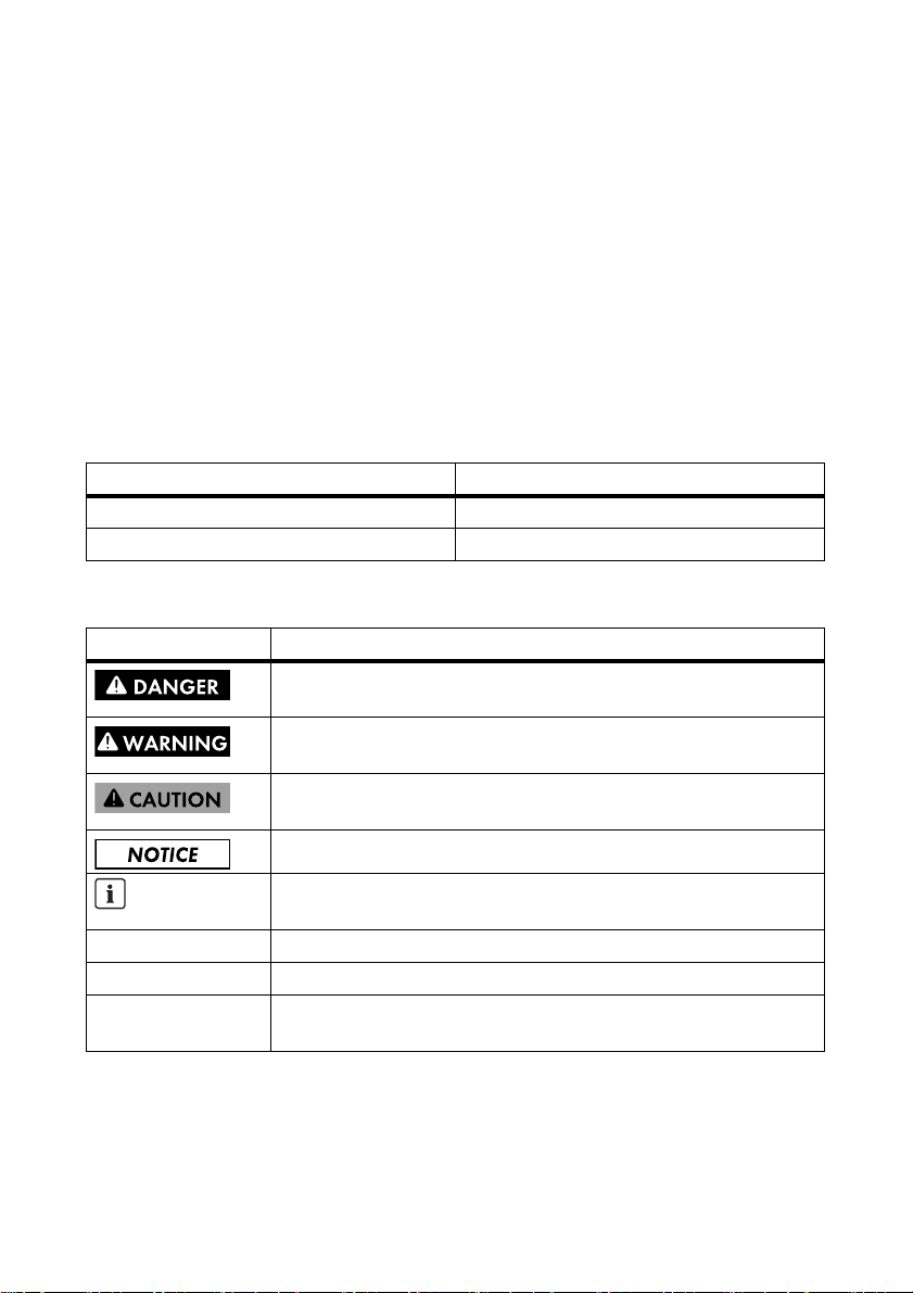
Figure1: Principle of a PV plant with SMA PV Offset Box and string inverter
The SMA PV Offset Box can be operated with both a string inverter and with an inverter with several
inputs. In an inverter with several inputs, the negative PV inputs must be internally bridged for this
purpose. This is the case with SMA multi-string inverters, providing that the DC switch-disconnector,
Electronic Solar Switch (ESS) is plugged in.
Installation Manual PVO-BOX-IA-en-10 7
Page 8
2 Safety SMA Solar Technology AG
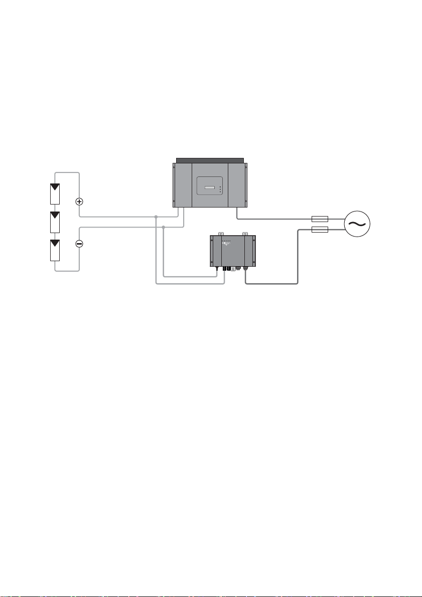
Figure2: Principle of a PV plant with SMA PV Offset Box and multi-string inverter
No more than 1 SMA PV Offset Box must be connected per inverter. Exceptions to this rule are
inverters with several inputs in which the negative DC inputs are not internally bridged.
1 SMA PV Offset Box per string can be connected to this type of inverter.
The SMA PV Offset Box can only be operated with PV plants having an insulation resistance
(including insulation resistance of the inverter) of at least 200 kΩ.
The SMA PV Offset Box must only be operated with PV arrays (modules and cabling) of protection
class II.
Before installing the SMA PV Offset Box, ensure that the permitted operating range of each
component is maintained at all times.
You may only operate the SMA PV Offset Box once you have obtained the appropriate approval
from both t he manufacture r of the PV modules and t he manu facturer of the inverter. Note any relevant
restrictions in the approvals, e.g., pertaining to the maximum output volt age of t he S MA P V Off set Box .
Any applications other than those described here shall be considered contrary to the appropriate
usage. Alternative uses or modifications to the SMA PV Offset Box will void the warranty claims and
operation permit.
Appropriate usage also includes compliance with all the supplied documentation. Keep this manual
in a convenient place for future reference.
8 PVO-BOX-IA-en-10 Installation Manual
Page 9

SMA Solar Technology AG 2 Safety
2.2 Qualifications of Skilled Persons
The work described in this document must be performed by skilled persons only. Skilled persons must
have the following qualifications:
• Knowledge of how an inverter works and is operated
• Training in how to deal with the dangers and risks involved in installing and operating electrical
devices and plants
• Training in the installation and commissioning of electrical devices and plants
• Knowledge of all applicable standards and directives
• Knowledge and observance of this document and all safety precautions
2.3 Safety precautions
Electric Shock
When the SMA PV Offset Box is in operation, voltage will be present in the PV array at night.
Prior to any maintenance work on the PV plant:
• Disconnect the inverter from all voltage sources (see the inverter installation manual).
• Disconnect the SMA PV Offset Box from all voltage sources (see Section9 "Disconnecting the
SMA PV Offset Box from Voltage Sources", page43).
If the output vol tage of the SMA PV Offs et Box is set too h igh, the insulation of the connected inverters,
PV modules or other DC-side components could be damaged. There is a risk of electric shock.
• Observe the maximum DC voltage of the PV modules, the inverter and any other DC-side
components (see manufacturer specifications).
• Only connect approved PV modules and inverters.
• For SMA inverters, observe additional specifications on maximum DC voltage in the datasheet
of the SMA PV Offset Box at www.SMA-Solar.com.
Electrostatic Discharge (ESD)
By touching electronic components you can cause damage to or destroy the SMA PV Offset Box
through electrostatic discharge (ESD).
• Earth yourself on an earthed object before touching any component inside the SMA PV Offset
Box Do not use the enclosure of the SMA PV Offset Box for this purpose, as it is not earthed.
Installation Manual PVO-BOX-IA-en-10 9
Page 10
3 Scope of Delivery SMA Solar Technology AG
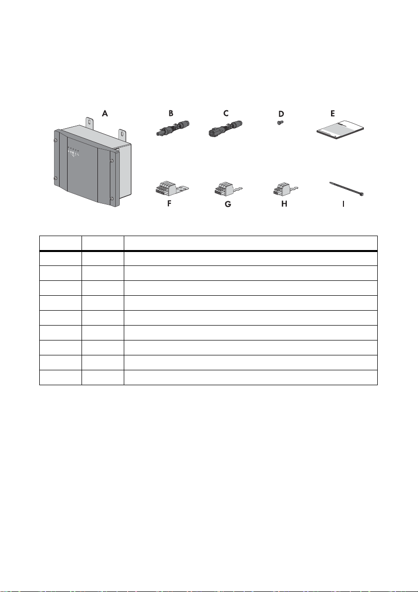
3 Scope of Delivery
Check the scope of delivery for completeness and any visible external damage. Contact your
specialist dealer if the delivery is incomplete or you find any damage.
Figure3: Components included in the scope of delivery
Item Quantity Description
A 1 SMA PV Offset Box
B 2 Positive DC connector
C 1 Negative DC connector
D 1Sealing plugs
E 1 Installation manual
F 1 4-pole plug with strain relief
G 1 3-pole plug with strain relief
H 1 2-pole plug with strain relief
I 6Cable tie
10 PVO-BOX-IA-en-10 Installation Manual
Page 11
SMA Solar Technology AG 4 Product Description
4 Product Description
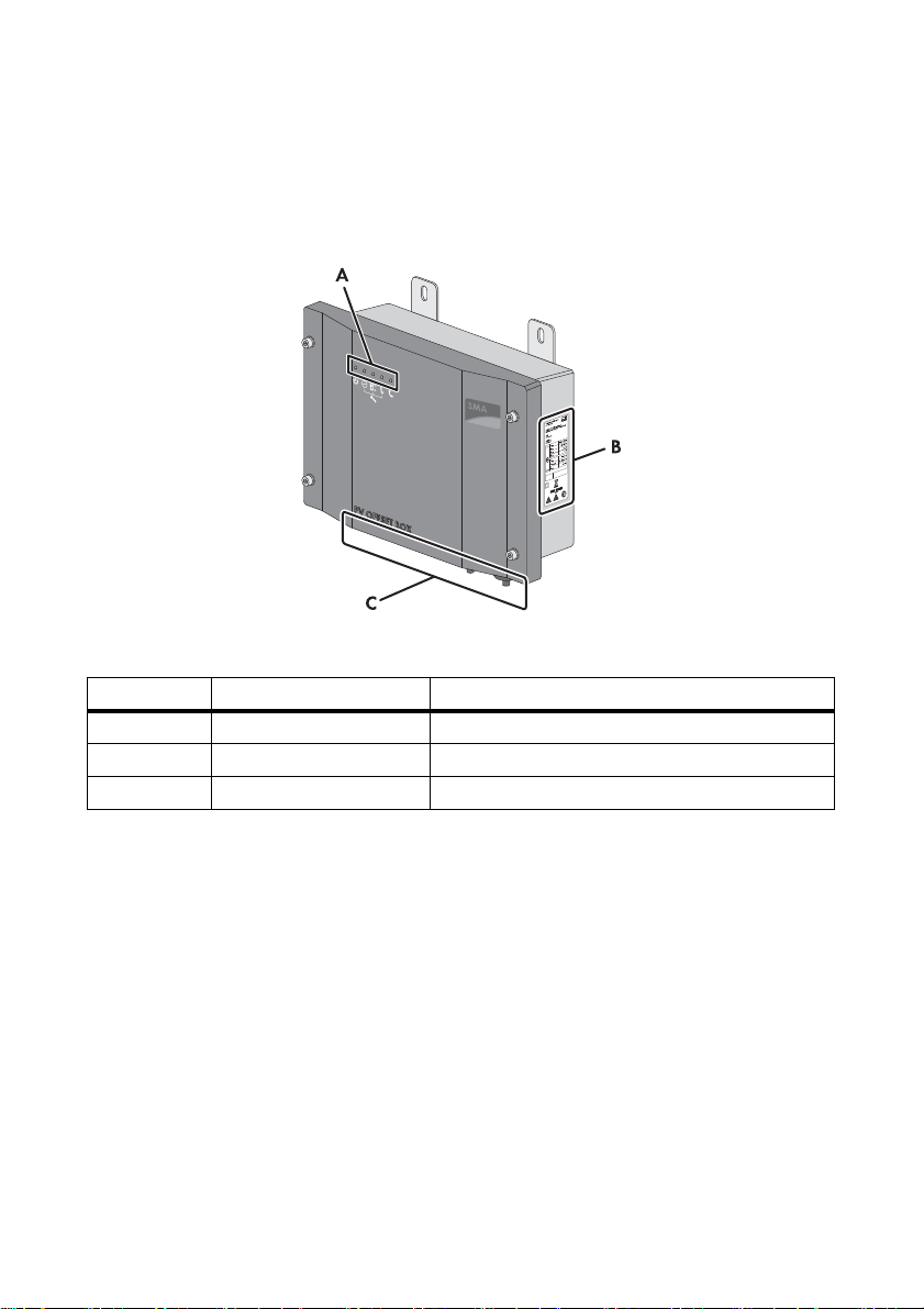
4.1 SMA PV Offset Box
The SMA PV Offset Box dissipates power-reducing charges in PV modules.
Figure4: Parts of the SMA PV Offset Box
Item Description Explanation
A LEDs LEDs for operation and fault display
B Type label ‒
C Connection area
The SMA PV Offset Box is connected in parallel with the inverter and applies a voltage against earth
to PV modules. It can apply a set voltage or automatically regulate its output voltage.
Depending on its configuration, the SMA PV Offset Box performs various functions. Overnight, it can
dissipate PV modules charges which have accumulated during the day. In continuous operation, the
SMA PV Offset Box regenerates PV modules whose efficiency was previously reduced.
The SMA PV Offset Box continually monitors the connection of the functional earthing (FE) and the
insulation of the PV plant. Prior to starting operation, the SMA PV Offset Box checks whether the
PV strings are reverse poled or interrupted. Faults are displayed via LEDs.
Installation Manual PVO-BOX-IA-en-10 11
Cable glands for the AC connection and DC connector
Page 12
4 Product Description SMA Solar Technology AG
4.2 Fault Indication Relay
An external fault indicator can be connected via the fault indication relay in the SMA PV Offset Box.
Depending on the type of electrical connection, the fault indicator is activated either in the event of a
disturbance or during fault-free operation of the SMA PV Offset Box.
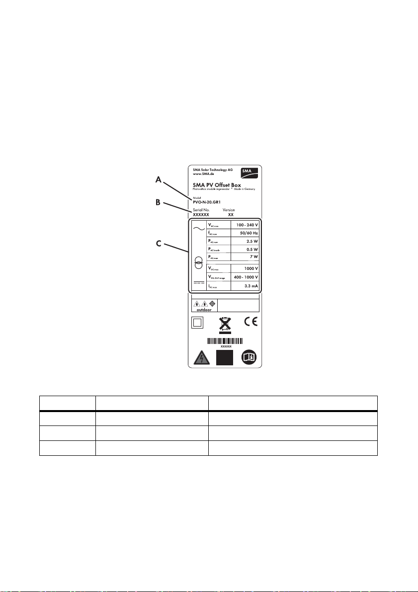
4.3 Type Label
The type label clearly identifies the SMA PV Offset Box. The type label is located on the right-hand
side of the enclosure.
Figure5: Layout of the type label
Item Description
A Model Device type
B Serial No. Serial number
C Device-specific characteristics ‒
The information on the type label will support you in the safe use of the SMA PV Offset Box and will
be needed when you contact the SMA Service Line. The type label must be permanently affixed to
the SMA PV Offset Box.
12 PVO-BOX-IA-en-10 Installation Manual
Page 13
SMA Solar Technology AG 4 Product Description
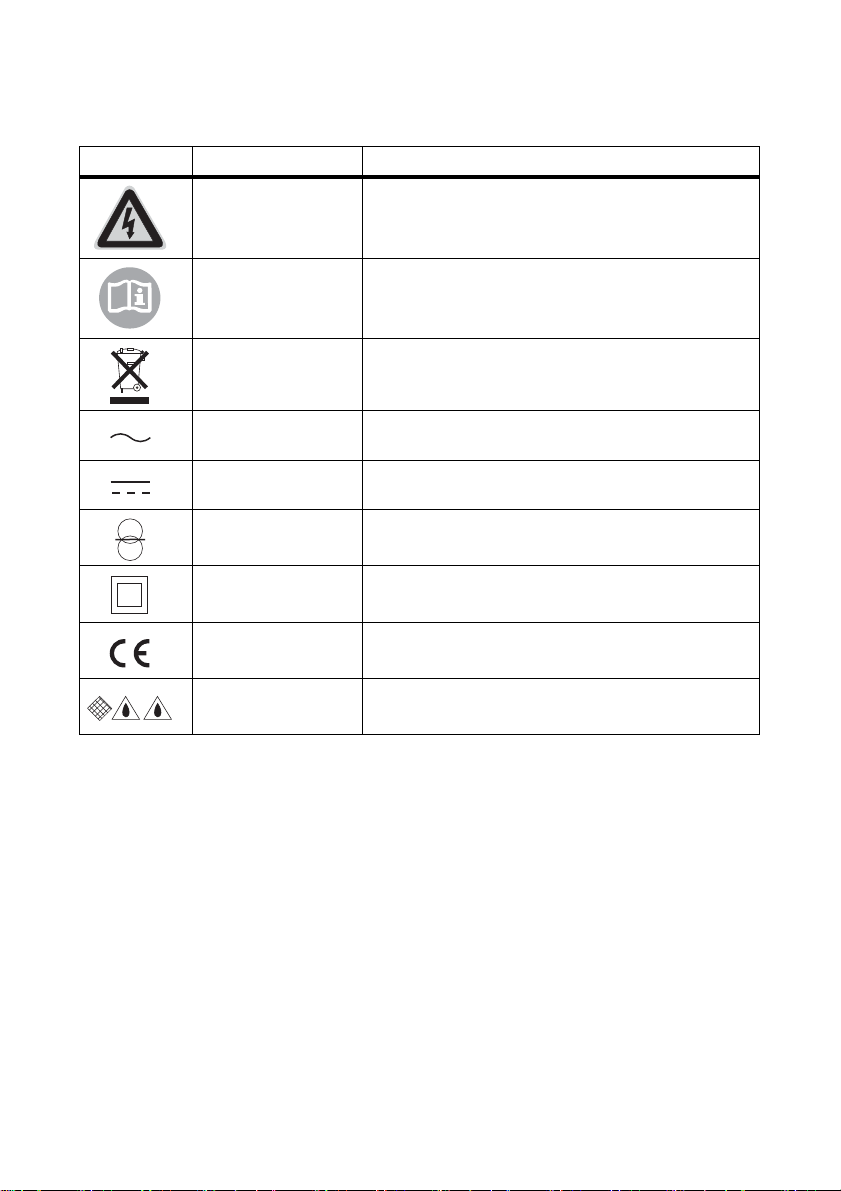
Symbols on the Type Label
Symbol Meaning Explanation
Danger to life due to
high voltages
The SMA PV Offset Box operates at high voltages. All
work on the SMA PV Offset Box must be performed by
skilled workers only.
Observe the
documentation.
Observe all the documentation supplied with the
SMA PV Offset Box.
Proper disposal Do not dispose of the SMA PV Offset Box with the
household refuse.
AC Alternating current
DC Direct current
With transformer The SMA PV Offset Box is equipped with a transformer.
Protection class II The protection insulation of the SMA PV Offset Box is
compliant with protection class II.
CE marking The SMA PV Offset Box complies with the requirements
of the applicable EC directives.
Degree of protection:
IP65
The SMA PV Offset Box is protected against dust
intrusion and water jets from any angle.
Installation Manual PVO-BOX-IA-en-10 13
Page 14

4 Product Description SMA Solar Technology AG
4.4 LEDs
Item Description Explanation
A Green LED Indicates the operating state of the SMA PV Offset Box.
B Red-yellow LED Indicates an FE connection fault or AC connection fault.
C Red-yellow LED Indicates a DC connection fault.
D Red-yellow LED Indicates an insulation fault.
E Red-yellow LED Indicates a device fault.
The LEDs for fault indication are 2-colour. They glow red if operation is currently interrupted. They
glow yellow if a fault has previously occurred, but normal operation is currently possible.
14 PVO-BOX-IA-en-10 Installation Manual
Page 15

SMA Solar Technology AG 5 Assembly
5 Assembly
5.1 Selecting the Mounting Location
Requirements for the mounting location:
Danger to life due to fire or explosion
Despite careful construction, electrical devices can cause fires.
• Do not mount the SMA PV Offset Box on flammable construction materials.
• Do not mount the SMA PV Offset Box in the vicinity of highly flammable materials.
• Do not mount the SMA PV Offset Box in potentially explosive areas.
☐ The installation site must be freely and safely accessible at all times without the necessity for any
auxiliary equipment (such as scaffolding or lifting platforms). Non-fulfillment of these criteria
may restrict servicing.
☐ The mounting surface must be even. The wall brackets of the SMA PV Offset Box must lie flush
with the mounting surface.
☐ The ambient temperature must be between − 25°C and +60°C.
☐ The LED display of the SMA PV Offset Box must be readable.
☐ The mounting location should be close to the inverter. If the device is mounted on the PV array,
support by SMA Service will not be possible.
Installation Manual PVO-BOX-IA-en-10 15
Page 16
5 Assembly SMA Solar Technology AG
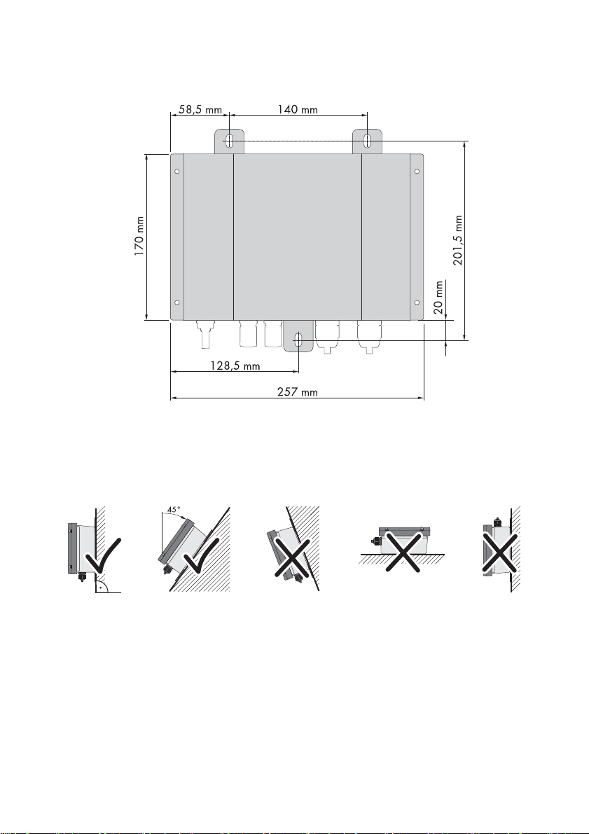
Dimensions for mounting:
Figure6: Dimensions of the SMA PV Offset Box and the drill holes for mounting
Observe the permitted mounting positions:
• Mount the SMA PV Offset Box in a vertical position or tilted backwards by max. 45°. The
connection area must point downwards.
Permitted and prohibited mounting positions
16 PVO-BOX-IA-en-10 Installation Manual
Page 17
SMA Solar Technology AG 5 Assembly
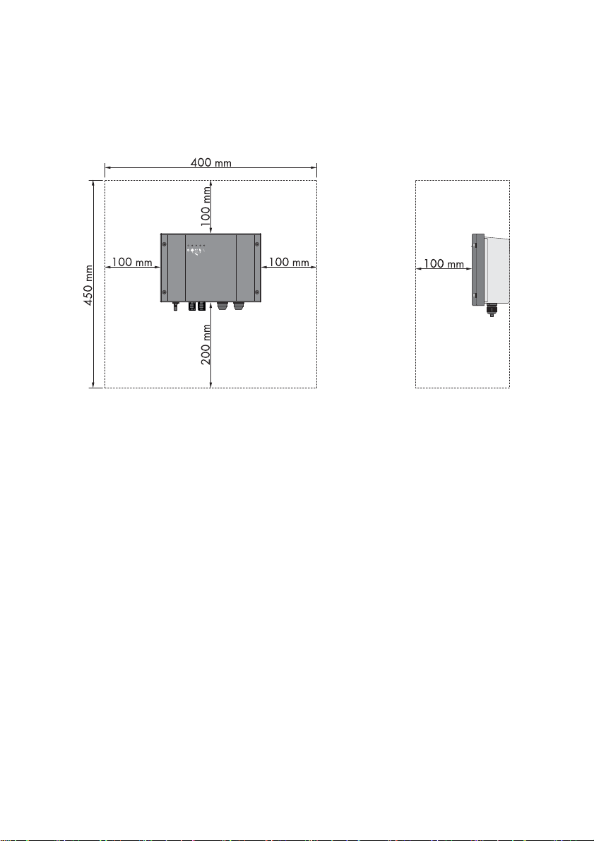
Observe recommended clearances:
• In order to have sufficient room for mounting, installation, and maintenance of the
SMA PV Offset Box, observe the recommended clearances. In addition, take the recommended
clearances of the inverter into account.
Figure7: Recommended clearances
Installation Manual PVO-BOX-IA-en-10 17
Page 18

5 Assembly SMA Solar Technology AG
5.2 Mounting the SMA PV Offset Box
1. Mark the position of the drill holes.
2.
Danger to life due to electric shock or explosion if you drill into utility lines.
There may be gas pipes or electric cables located behind the mounting points which could be
damaged when you drill the holes for the SMA PV Offset Box.
• Make sure that there are no utility lines behind the mounting points.
3. Drill the holes.
4. Insert the wall plugs.
5. Screw the SMA PV Offset Box to the mounting
surface.
6. Check that the SMA PV Offset Box is fixed securely to the surface.
18 PVO-BOX-IA-en-10 Installation Manual
Page 19

SMA Solar Technology AG 6 Setting the Operating Mode and Output Voltage
6 Setting the Operating Mode and Output Voltage
Setting Options for the Operating Mode
The SMA PV Offset Box has the following operating modes:
• Night operation: the SMA PV Offset Box emits voltage overnight and is inactive during the day.
• Continuous operation: the SMA PV Offset Box continuously applies a fixed voltage to the
PV modules. During the continuous operation of the SMA PV Offset Box, the inverter must not
be connected to the electricity grid. Afterwards, you must manually set the SMA PV Offset Box
to another operating mode and restart the inverter.
• Temporary operation: the SMA PV Offset Box runs continuously for 10 days at a fixed set
voltage and thereafter switches automatically to night mode. As lon g as the SMA PV O ffset Box
is continuously applying voltage, the inverter must not be connected to the electricity grid.
There are two switch positions for the operating mode "Temporary operation":
"Temporary operation 1" and "Temporary operation 2". After switching between these
positions, the SMA PV Offset Box restarts temporary operation and runs for another 10 days in
continuous operation.
Setting Options for Output Voltage
The output voltage of the SMA PV Offset Box can be regulated in two ways, as follows:
• Fixed voltage setting: for fast regeneration of the PV modules, it is recommended to set the
largest permissible fixed voltage. The output voltage can be set to a fixed voltage of 400 V,
550 V, 700 V or 1,000 V. The setting of a fixed voltage is required for the operating modes
"Continuous operation" and "Temporary operation" and is optional for the operating mode
"Night mode".
• Automatic voltage regulation: this setting is only required for the operating mode "Night mode".
With automatic voltage regulation, the magnitude of the output voltage is based on the PV
voltage of the previous day. For th e au tom ati c volta ge re gulation, there are two switch positions.
If at t he S MA P V Of fse t Bo x on e te rmi nal is a ssi gne d wi th P V+, select switch position "Automatic,
1 string". If two terminals are assigned with PV+, select switch position "Automatic, 2 strings".
Obtain approval from module manufacturer
Ask your module manufacturer which operating mode setting is recommended for your
PV plant.
Installation Manual PVO-BOX-IA-en-10 19
Page 20

6 Setting the Operating Mode and Output Voltage SMA Solar Technology AG
Requirements for Setting a Fixed Output Voltage
If you set a fixed output voltage on the SMA PV Offset Box, this must not exceed the maximum system
voltage of the PV modules, the inverter or other DC-side components.
General information on the maximum DC voltage of the PV modules and inv erter s can be found in the
respective product documentation. Please refer to the manufacturer approvals on the PV modules and
inverters for the specific requirements for operation with the SMA PV Offset Box.
The following applies to SMA inverters:
• For most SMA inverter types, the maximum voltage output to be set on the SMA PV Offset Box
is equal to the maximum DC voltage of the inverter.
• The inverters approved by SMA are listed in the datasheet of the SMA PV Offset Box at
www.SMA-Solar.com.
Permissible Combinations of Operating Mode and Output Voltage
Operating
mode
Voltage
setting
Explanation
Night mode fixed This setting is suitable for the overnight regeneration of
PV modules with severely reduced power. If you set the output
voltage on the SMA PV Offset Box to the maximum system
voltage, optimum regeneration will take place.
Continuous
operation
automatic,
1 string
automatic,
2 strings
fixed This operating mode is suitable for the rapid regeneration of
This setting is suitable for preventing power reductions in the
PV modules. Since regeneration takes place overnight, inverter
operation does not need to be interrupted. For automatic voltage
regulation, you will need to set the number of connected strings.
PV modules with severely reduced power. During continuous
operation the inverter must be disconnected from the grid.
Temporary
operation
fixed This operating mode is suitable for the rapid regeneration of
PV modules with severely reduced power. The SMA PV Offset Box
runs continuously for 10 days at a fixed set voltage and then
switches to night mode with automatic voltage regulation. During
continuous operation the inverter must be disconnected from the
grid.
Setting Faults
A setting fault is indicated by 3 red flashing LEDs. If the setting of the output voltage is not suitable for
the selected operating mode, the SMA PV Offset Box displays a setting fault during commissioning
(see Section10 "Troubleshooting", page45). A setting fault will also be displayed If you have
selected an unassigned switch position. As long as a setting fault is present, the SMA PV Offset Box
will not start operation.
20 PVO-BOX-IA-en-10 Installation Manual
Page 21

SMA Solar Technology AG 6 Setting the Operating Mode and Output Voltage
Overview of the Configuration Area
Item Explanation
M Rotary switch for setting the operating mode
V Rotary switch for setting the output voltage
Procedure
1. If the SMA PV Offset Box is already in operation, disconnect it from all voltage sources
(see Section 9).
2. Unscrew all the enclosure lid screws and remove the lid.
3. Set the rotary switch M to the desired operating mode.
Switch position Operating mode
0 No selection (default setting)
1Night mode
3 Continuous operation
5 Temporary operation 1
7 Temporary operation 2
4. Set the rotary switch V to the desired output voltage.
Switch position Output voltage
0 No selection (default setting)
1 400 V
3 550 V
5 700 V
7 1,000 V
9 automatic, 1 string
B automatic, 2 strings
Installation Manual PVO-BOX-IA-en-10 21
Page 22

6 Setting the Operating Mode and Output Voltage SMA Solar Technology AG
Danger to life due to electric shock
If the output voltage of the SMA PV Offset Box is set too high, the insulation of the connected
inverters, PV modules or other DC-side components could be damaged. There is a risk of
electric shock.
• Observe the maximum DC voltage of the PV modules, the inverter and any other DC-side
components (see manufacturer specifications).
• Only connect approved PV modules and inverters.
• For SMA inverters, observe additional specifications on maximum DC voltage in the
datasheet of the SMA PV Offset Box at www.SMA-Solar.com.
22 PVO-BOX-IA-en-10 Installation Manual
Page 23

SMA Solar Technology AG 7 Electrical Connection
7 Electrical Connection
7.1 Overview of the Connection Area
7.1.1 View from Below
Figure8: Exterior view of the connection area
Item Description Explanation
A DC connector PV‒ Negative DC terminal
B DC connector PV+ Positive DC terminals
C Reset button For resetting the LED display
D Enclosure opening M20 For looping the grid connection (AC) through to
another SMA PV Offset Box
E Enclosure opening M20 For the grid connection (AC) of the
SMA PV Offset Box
Installation Manual PVO-BOX-IA-en-10 23
Page 24

7 Electrical Connection SMA Solar Technology AG
7.1.2 Interior View
Figure9: Interior view of the SMA PV Offset Box
Item Description Explanation
A Connection socket Connection socket for fault indication relay
B Connection socket Connection socket for AC connection
C Connection socket Connection socket for FE
24 PVO-BOX-IA-en-10 Installation Manual
Page 25

SMA Solar Technology AG 7 Electrical Connection
7.2 AC Connection
7.2.1 Conditions for AC Connection
Cable Requirements:
☐ When using a fault indication relay: the AC cable must have at least 4 wires for the phase (L),
the neutral conductor (N), the functional earth (FE) and the fault indication relay. In most
countries, the green-yellow conductor for protective earth (PE) must not be used for functional
earthing.
☐ When not using a fault indication relay: the AC cable must have at least 3 wires for L, N and
FE. In most countries, the green-yellow conductor for protective earth (PE) must not be used for
functional earthing.
☐ All cables must be double-insulated.
☐ External diameter: 5 mm - 13 mm.
☐ Conductor cross-section: 0.5 mm
Miniature Circuit-Breaker
Danger to life due to fire.
If a generator (inverter) and a load (SMA PV Offset Box) are connected to the same miniature
circuit-breaker, the protective function of the miniature circuit-breaker is no longer guaranteed. The
currents from the inverter and the electricity grid can accumulate to overcurrents which are not
detected by the miniature circuit-breaker.
• Fuse the SMA PV Offset Box with a separate miniature circuit-breaker. Tip: you can connect
up to 50 SMA PV Offset Boxes to the same miniature circuit-breaker.
• Observe the maximum permissible fuse protection of the SMA PV Offset Box when selecting
the miniature circuit-breaker (see Section12 "Technical Data", page49).
2
- 1.5 mm2.
Inverter Earthing
Danger to life due to electric shock
If the SMA PV Offset Box is operated with an inverter with AC connector and the AC connector is
disconnected during operation of the SMA PV Offset Box, the inverter enclosure will be live.
• Connect a second, non-disconnectable protective conductor to the inverter.
• Do not pull the AC connector out during operation with an SMA PV Offset Box.
Installation Manual PVO-BOX-IA-en-10 25
Page 26

7 Electrical Connection SMA Solar Technology AG
FE Connection:
Since the SMA PV Offset Box applies a voltage against earth to the PV modules, an operational
current flows through the protective conductor of the SMA PV Offset Box. In a standard-compliant
installation, this current is not allowed to flow through a PE conductor . For this reason, you must use
an FE conductor. You can connect the FE conductor either to the substructure of the PV plant or to an
equipotential bonding busbar.
Connection Options for the Potential-Free Fault Indication Relay
You can connect a separate load optionally for fault indication or for fault-free operation. You can
connect the fault indication relays to an external voltage source or use the voltage between L and N.
Figure10: Connection principle for operation and fault indication
26 PVO-BOX-IA-en-10 Installation Manual
Page 27

SMA Solar Technology AG 7 Electrical Connection
Description Explanation
B Fault-free operation
FFault
1 Terminal 1 of the fault indication relay
2 Terminal 2 of the fault indication relay
3 Terminal 3 of the fault indication relay
Connection of several SMA PV Offset Boxes:
The AC connection can be looped through to several SMA PV Offset Boxes. In total, you can connect
up to 50 SMA PV Offset Boxes to one AC connection in this way.
Figure11: Connection of several SMA PV Offset Boxes
7.2.2 Connecting the SMA PV Offset Box to the Electricity Grid (AC)
1. Slightly release the swivel nut of the cable gland.
2. Strip the AC cable by by 130 mm.
3. Strip the insulated wires of the AC cable by 7 - 8 mm.
4. Route the AC cable through the cable gland to the AC terminals in the SMA PV Offset Box.
Installation Manual PVO-BOX-IA-en-10 27
Page 28

7 Electrical Connection SMA Solar Technology AG
5. Plug the supplied 4-pole plug into the centre socket
in the SMA PV Offset Box.
6. Connect L and N to the plug as follows:
•Connect L to the first or second terminal.
•Connect N to the third or fourth terminal.
7.
Danger to life due to electric shock
If the cables slip out of the terminal due to excessive tension, the enclosure will carry live
voltage.
• Attach the supplied cable tie to relieve the
tension.
8. Plug the supplied 2-pole plug into the right-hand
socket in the SMA PV Offset Box.
9. Connect FE to the plug.
28 PVO-BOX-IA-en-10 Installation Manual
Page 29

SMA Solar Technology AG 7 Electrical Connection
10.
Danger to life due to electric shock
If the cables slip out of the terminal due to excessive tension, the enclosure will carry live
voltage.
• Attach the supplied cable tie to relieve the
tension.
11. Screw the swivel nut firmly onto the cable gland.
12. If no fau lt indication r elay is to b e connecte d, scr ew
the enclosure lid onto the SMA PV Offset Box using
the 4 screws (torque: 5 Nm).
Installation Manual PVO-BOX-IA-en-10 29
Page 30

7 Electrical Connection SMA Solar Technology AG
7.2.3 Connecting the Fault Indication Relay
If a fault indication relay is required, connect it as follows (see Connection Principle, P. 26):
13. Plug the supplied 3-pole plug into the left-hand
socket in the SMA PV Offset Box.
14. If you wish to receive an operation signal, connect
the wires to terminals 1 and 2 of the plug.
15. If you wish to receive a fault signal, connect the
wires to terminals 2 and 3 of the plug.
16.
Danger to life due to electric shock
If the cables slip out of the terminal due to excessive tension, the enclosure will carry live
voltage.
• Attach the supplied cable tie to relieve the
tension.
17. Connect the fault indication relay either to an external voltage source or connect to L and N.
The maximum supply voltage for the fault indicator is 240 V AC or 30 V DC. The maximum
switching current is 1 A.
30 PVO-BOX-IA-en-10 Installation Manual
Page 31

SMA Solar Technology AG 7 Electrical Connection
18. Screw the enclosure lid onto the SMA PV Offset
Box using the 4 screws (torque: 5 Nm).
7.2.4 Connecting Additional SMA PV Offset Boxes
The AC cable is looped through between each SMA PV Offset Box.
1. Disconnect the previously installed SMA PV Offset Box from all voltage sources (see Section 9).
2. Slightly release the swivel nut of the second cable
gland M20 on the previously installed
SMA PV Offset Box.
3. Remove the sealing plug from the cable gland.
4. Route the cable through the cable gland to the terminals in the previously installed
SMA PV Offset Box.
5. Remove the cable ties.
6. Connect L and N to the 4-pole plug as follows:
•Connect L to the first or second free terminal.
•Connect N to the third or fourth free terminal.
Installation Manual PVO-BOX-IA-en-10 31
Page 32

7 Electrical Connection SMA Solar Technology AG
7.
Danger to life due to electric shock
If the cables slip out of the terminal due to excessive tension, the enclosure will carry live
voltage.
• Attach the supplied cable tie to relieve the
tension.
8. Connect FE to the free terminal of the 2-pole plug.
9.
Danger to life due to electric shock
If the cables slip out of the terminal due to excessive tension, the enclosure will carry live
voltage.
• Attach the supplied cable tie to relieve the
tension.
10. Route the cable through the cable gland to the second SMA PV Offset Box and connect L, N
and FE to the respective terminals in the same manner.
11. If a fault indication relay is required, loop it through as follows (see Connection Principle, P. 26).
32 PVO-BOX-IA-en-10 Installation Manual
Page 33

SMA Solar Technology AG 7 Electrical Connection
12. Screw all enclosure lids onto the
SMA PV Offset Boxes using the 4 screws
(torque: 5 Nm).
7.3 DC Connection
7.3.1 Conditions for DC Connection
The SMA PV O ffset Box is connect ed in pa rallel to t he inverter. Depending on the type of inverter, you
will need different DC connection options on the inverter for this.
If the necessary DC terminals are free on the inverter, you can con nec t th e SM A PV O ffs et B ox d irec tly
to the inverter. If the necessary terminals are not free, you will have to connect the SMA PV Offset Box
via a Y plug. An individual Y plug will be needed for the DC output of each SMA PV Offset Box which
cannot be connected directly to the inverter (for order numbers, see Section 13).
Danger of electric arcs if the DC circuit is interrupted by Y plugs
• Y plugs must not be visible or freely accessible in close proximity to the inverter.
• The DC circuit must not be interrupted by Y plugs.
• Follow the procedure for disconnection of the inverter (see installation manual of the inverter).
• Follow the procedure for disconnection of the SMA PV Offset Box (see Section 9).
The DC connection cables must be fitted with the supplied DC connectors for connection to the
SMA PV Offset Box (see Section7.3.1 "Conditions for DC Connection", page33).
Installation Manual PVO-BOX-IA-en-10 33
Page 34

7 Electrical Connection SMA Solar Technology AG
Connection of String Inverters with One Single Input
For a string inverter, 1 positive and 1 negative DC terminal is required on the SMA PV Offset Box.
Only in the operating modes "Continuous operation" or "Temporary operation" will both positive DC
outputs on the SMA PV Offset Box need to be assigned. If only 1 DC input is to be connected, the
second positive DC terminal on the SMA PV Offset Box must also be connected to PV+ on the inve rter.
The following DC connection options are possible (as examples):
Figure12: DC connection options for a string inverter
Connection Options
Option Description
A String inverter with DC input not assigned - operating mode "Night mode"
B String inverter with all DC inputs assigned - operating mode "Night mode"
C S tri ng i nverter wit h all DC inp uts assigne d - o peratin g mo de "Continuous operation"
or "Temporary operation"
34 PVO-BOX-IA-en-10 Installation Manual
Page 35

SMA Solar Technology AG 7 Electrical Connection
Cable Connections
Connection Description SUNCLIX
1 PV+ connection cable SMA PV Offset Box to inverter or
2 x positive (+)
Y distribution
2 PV − connection cable SMA PV Offset Box to inverter or
2 x negative ( − )
Y distribution
3 PV+ connection cable PV array to inverter 1 x positive (+)
4 PV − connection cable PV array to inverter 1 x negative ( − )
5 PV+ connection cable Y distribution to inverter 1 x positive (+),
1 x negative ( − )
6 PV − connection cable Y distribution to inverter 1 x negative ( − ),
1 x positive (+)
7 PV+ Y distribution 2 x negative ( − ),
1 x positive (+)
8 PV − Y distribution 2 x positive (+),
1 x negative ( − )
Connection of Inverters with Several Independent Inputs
For an inverter with 2 independent inputs and 1 internally bridged negative DC terminal, such as in
SMA multi-string inverters, 1 positive DC terminal per input and 1 negative DC terminal at one of the
two inputs are required. As a result, you will only need 1 SMA PV Offset Box for all the PV modules
connected to the inverter. Should the negative DC inputs of the inverter not be internally bridged
(s ee i nve rte r do cum entatio n), the SMA PV O ffs et B ox will o nly apply voltage to one string. In this case,
you must connect 1 SMA PV Offset Box per string.
For an inverter with more than 2 independent inputs, 1 positive DC terminal is required at each input
to which voltage is applied first in the morning and last at night. In addition, 1 negative DC terminal
is required at one of these inputs.
If an inverter has several independent inputs but only 1 input is assigned, just 1 positive and 1
negat ive DC t erminal will be requir ed at the as signed input. Only in the operating modes "Continuous
operation" or "Temporary operation" do both positive DC outputs on the SMA PV Offset Box have to
be assigned. In the event that only 1 DC input is to be connected, the positive DC outputs of the
SMA PV Offset Box must be bridged with a Y plug.
Installation Manual PVO-BOX-IA-en-10 35
Page 36

7 Electrical Connection SMA Solar Technology AG
The following DC connection options are possible (as examples):
Figure13: DC connection options for a multi-string inverter
Connection Options
Option Description
A Multi-string inverter with no DC input assigned - all operating modes
B
Multi-string inverter with one DC input area completely assigned – all operating modes
C Multi-string inverter with all DC inputs completely assigned – all operating modes
Cable Connections
Connection Description SUNCLIX
1 PV+ connection cable SMA PV Offset Box to inverter or
2 x positive (+)
Y distribution
2 PV − connection cable SMA PV Offset Box to inverter or
2 x negative ( − )
Y distribution
3 PV+ connection cable PV array to inverter 1 x positive (+)
4 PV − connection cable PV array to inverter 1 x negative ( − )
5 PV+ connection cable Y distribution to inverter 1 x positive (+),
1 x negative ( − )
6 PV − connection cable Y distribution to inverter 1 x negative ( − ),
1 x positive (+)
7 PV+ Y distribution 2 x negative ( − ),
1 x positive (+)
36 PVO-BOX-IA-en-10 Installation Manual
Page 37

SMA Solar Technology AG 7 Electrical Connection
Connection Description SUNCLIX
8 PV − Y distribution 2 x positive (+),
1 x negative ( − )
7.3.2 Assembling the DC Connectors
Figure14: DC connector
Item Description
A Negative DC connector
B Positive DC connector
Cable Requirements:
☐ External diameter: 5 mm - 8 mm.
☐ Cable cross-section: 2.5 mm² - 6 mm².
Proceed as follows to assemble each DC connector.
1. Strip 12 mm off the cable insulation.
2. Lead the stripped cable all the way into the DC
connector. Be sure to observe the correct polarity.
Installation Manual PVO-BOX-IA-en-10 37
Page 38

7 Electrical Connection SMA Solar Technology AG
3. Push the clamping bracket down.
☑ The clamping bracket clicks audibly into place.
☑ The stranded wire is visible inside the clamping
bracket chamber.
✖ You cannot see the stranded wire inside the clamping bracket chamber.
The cable is not correctly in place.
• Release the clamping bracket. To do so,
insert a 3.5 mm screwdriver into the
clamping bracket and lever it open.
• Remove the cable and go back to step 2.
4. Push the swivel nut up to the thread and tighten (torque: 2 Nm).
38 PVO-BOX-IA-en-10 Installation Manual
Page 39

SMA Solar Technology AG 7 Electrical Connection
7.3.3 Connecting the PV Array (DC)
1. Disconnect the SMA PV Offset Box from all voltage sources (see Section 9).
2. If the necessary DC terminals are free on the
inverter, connect the SMA PV Offset Box directly to
the inverter. To do this, fit the connection cables with
the respective mating connectors.
3. If the necessary DC terminals are not free on the inverter, connect the respective DC outputs of
the SMA PV Offset Box using Y plugs, as follows:
• Disconnect the PV cables from the PV array.
• Split the PV cables between the inverter and
PV array.
• Fit the open cable ends with mating connectors
and connect to the Y plug. Connect the inverter
to the plug which has a direct connection to the
PV array.
Installation Manual PVO-BOX-IA-en-10 39
Page 40

7 Electrical Connection SMA Solar Technology AG
• Connect the SMA PV Offset Box to the other
branch of the Y plug. To do this, fit the cables
with corresponding mating connectors.
4. Connect the PV cables to the PV array.
5. If a DC output on the SMA PV Offset Box is not required, create a hermetic seal with a DC plug
connector and sealing plugs. Do NOT plug sealing plugs directly into the DC output on the
SMA PV Offset Box.
• Push the clamping bracket of the unneeded DC
connector down (1) and push the swivel nut up
to the thread (2).
• Insert the sealing plug into the DC connector.
• Push the swivel nut up to the thread and tighten
(torque: 2 Nm).
• P lug the DC c onne cto r wi th s eal ing plug int o the
DC output of the SMA PV Offset Box.
40 PVO-BOX-IA-en-10 Installation Manual
Page 41

SMA Solar Technology AG 8 Commissioning
8 Commissioning
Commissioning for the operating modes "Continuous operation" or "Temporary
operation"
For the operating modes "Continuous operation" and "Temporary operation" of the
SMA PV Offset Box, the inverter must not yet be fully commissioned. The PV cables must be
co nne cte d to the inv ert er a nd t he D C sw itc h-d isc onn ect or c los ed s o th at t he S MA PV O ffs et B ox
can apply voltage to the PV modules. However, during continuous operation, the inverter must
not be connected to the electricity grid. The miniature circuit-breaker must be switched off.
After completion of continuous operation or after the first 10 days of temporary operation, the
inverter must be re-commissioned.
Operation of the SMA PV Offset Box with SMA multi-string inverters
In SMA multi-string inverters, the strings in the inverter are disconnected by the pulling the
Electronic Solar Switch (ESS) out.
If the SMA PV Offset Box is commissioned while the inverter remains disconnected (e.g. during
continuous operation), the SMA PV Offset Box will only apply voltage to one string.
• Prior to commissioning the SMA PV Offset Box with a disconnected SMA multi-string
inverter, re-plug the ESS on the inverter.
Requirements:
☐ SMA PV Offset Box is fixed firmly to the wall.
☐ Operating mode and output voltage are set correctly.
☐ AC cable is correctly connected.
☐ DC cables are correctly connected.
☐ Unnecessary AC terminals are closed with the corresponding sealing plugs.
☐ Unused DC inputs are closed with the corresponding DC connectors and sealing plugs
Installation Manual PVO-BOX-IA-en-10 41
Page 42

8 Commissioning SMA Solar Technology AG
Procedure
1.
Danger to life due to electric shock
During operation, voltages up to 1,000 V are present in the SMA PV Offset Box.
• Ensure that the cover is securely screwed on.
2. If the SMA PV Offset Box is to be used in the operating modes "Continuous operation" or
"Temporary operation":
– Connect PV cables to the inverter.
– Close DC switch-disconnector on the inverter.
– Commission the inverter as far as possible (see inverter installation manual) without
connecting the inverter to the electricity grid.
– Leave the miniature circuit-breaker of the inverter switched off.
3. If the SMA PV Offset Box is to be used in the operating mode "Night operation", commission
the inverter (see inverter installation manual).
4. Switch the miniature circuit-breaker of the SMA PV Offset Box on.
☑ The green LED on the SMA PV Offset Box is glowing or flashing. The SMA PV Offset Box is
in operation.
✖ One or more LEDs are glowing red or all LEDs are off.
A fault has occurred.
• Rectify the fault (see Section10 "Troubleshooting", page45).
42 PVO-BOX-IA-en-10 Installation Manual
Page 43

SMA Solar Technology AG 9 Disconnecting the SMA PV Offset Box from Voltage Sources
9 Disconnecting the SMA PV Offset Box from Voltage
Sources
1. Disconnect the inverter from all voltage sources (see the inverter installation manual).
2. Switch off the miniature circuit-breaker of the SMA PV Offset Box and secure against inadvertent
re-connection.
3. If a fault indication relay is connected, switch off the voltage supply to the fault indication relay
and secure against inadvertent re-connection.
4.
Danger to life due to high voltages in the PV array
During operation with the SMA PV Offset Box, dangerously high voltages may be present at
the PV array due to leakage capacitances.
• Wait one minute for the PV array to discharge before pulling the DC connectors.
5.
Danger of electric arcs if the DC circuit is interrupted by Y plugs
• Do not use Y plugs to interrupt the DC circuit.
• Release and remove all DC connectors on
the SMA PV Offset Box. To do this, insert a
flat-blade screwdriver (blade width: 3.5 mm)
into one of the side slots and pull the DC
connectors straight down. Do NOT PULL
ON THE CABLE.
6. Using a suitable multimeter, ensure that no voltage against earth (FE) is present on the DC
outputs of the SMA PV Offset Box. Only use multimeters with a DC input voltage range up to at
least 1,000 V.
7.
Danger to life due to high voltages
The SMA PV Offset Box takes 1 minute to discharge.
• Wait 1 minute before opening the enclosure lid.
Installation Manual PVO-BOX-IA-en-10 43
Page 44

9 Disconnecting the SMA PV Offset Box from Voltage Sources SMA Solar Technology AG
8.
Damage to the SMA PV Offset Box due to electrostatic discharge
The components inside the SMA PV Offset Box can be destroyed by electrostatic discharge.
• Earth yourself before touching any components. Do not use the enclosure of the
SMA PV Offset Box for this purpose, as it is not earthed.
9. Unscrew all the enclosure lid screws and remove the lid.
10. Ensure that no voltage is present between L and N on the AC terminal using a suitable
multimeter.
11. Ensure that no voltage is present between L and FE on the AC terminal using a suitable
multimeter.
12. Ensure that no voltage is present between any fault indication relay terminal and FE using a
suitable multimeter.
44 PVO-BOX-IA-en-10 Installation Manual
Page 45

SMA Solar Technology AG 10 Troubleshooting
10 Troubleshooting
10.1 LED Displays
The LEDs for fault indication are 2-colour. They glow red if operation is currently interrupted. They
glow yellow if a fault has previously occurred, but normal operation is currently possible.
The possible combinations are given in the following table. The "x" entry in the table means that the
previous display of the LED is retained.
Description and corrective measure
Flashing
green
Green x x x x Operation
x Yellow,
x x Yellow,
x x x x Ready for operation
xxxFE connection fault or AC connection fault:
red
xxDC connection fault:
red
– L / N swapped
– N not connected (SMA PV Offset Box
– FE connection interrupted
– Voltage difference between connected
• Check AC-side installation.
– DC connections reverse poled
– DC connection to PV array interrupted
– Installed in an area with insufficient
– S MA PV Offse t Box is dis connected on
– Regeneration time too short (average
• Check DC-side installation.
connected between L1 and L2)
N conductor and FE larger than 50 V
(AC or DC)
irradiation, or irradiation interrupted
during the day
the AC or DC side during the day.
night period is less than 5 hours)
Installation Manual PVO-BOX-IA-en-10 45
Page 46

10 Troubleshooting SMA Solar Technology AG
Description and corrective measure
x xxYellow,
red
xInsulation fault:
– Insulation resistance (including
inverter) against earth less than
200 kΩ
– Earth fault in the PV array
– Inverter and PV Offset Box in operation
simultaneously
• Check PV array for earth fault
(see inverter installation manual).
x xxxYellow,
red
Device fault
• Contact the SMA Service Line
(see Section14 "Contact", page52).
Off Flashing
red
Flashing
red
Flashing
red
xSetting fault:
– The operating mode and output
voltage settings are not compatible
– Prohibited switch position selected
• Configure the SMA PV Offset Box
correctly (see Section8 "Commissioning",
page41).
Off Off Off Off Off No supply voltage
• Check AC-side installation.
46 PVO-BOX-IA-en-10 Installation Manual
Page 47

SMA Solar Technology AG 10 Troubleshooting
10.2 Resetting the Fault Display
After a reset, the SMA PV Offset Box checks whether there is still any fault present. After a waiting
period, the display is updated. Any faults still present will be re-displayed via red LEDs. The display
of previous faults via yellow LEDs will be deleted.
You can only reset the LED fault display by pressing the reset button. A grid failure or AC-side
disconnection of the SMA PV Offset Box will not influence the LED display.
1. Press the reset button on the bottom of the SMA PV Offset Box.
☑ The fault display is reset.
2. Wait 6 minutes.
3. Read off the LED display again.
☑ The green LED on the SMA PV Offset Box is glowing or flashing. The SMA PV Offset Box is
in operation.
✖ One or more LEDs are glowing red or all LEDs are off.
A fault has occurred.
• Eliminate the fault and reset the fault display.
Installation Manual PVO-BOX-IA-en-10 47
Page 48

11 Decommissioning SMA Solar Technology AG
11 Decommissioning
11.1 Disassembling the SMA PV Offset Box
1. Disconnect the SMA PV Offset Box from all voltage sources (see Section9 "Disconnecting the
SMA PV Offset Box from Voltage Sources", page43).
2. Remove all connection cables from the SMA PV Offset Box.
3. Loosen the fastening screws and remove the SMA PV Offset Box from the mounting surface.
4. Screw the enclosure lid onto the SMA PV Offset Box with the 4 screws.
11.2 Packing the SMA PV Offset Box
• Pack the SMA PV Offset Box. Use the original packaging or packaging suitable for the weight
and dimensions of the SMA PV Offset Box (see Section12 "Technical Data", page49).
11.3 Disposing of the SMA PV Offset Box
• Dispose of the SMA PV Offset Box at the end of its service life in accordance with the disposal
regulations for electronic waste currently applicable at the installation site.
48 PVO-BOX-IA-en-10 Installation Manual
Page 49

SMA Solar Technology AG 12 Technical Data
12 Technical Data
AC Input
Nominal AC voltage 100 V / 110 V / 120 V / 220 V / 230 V /
240 V
AC mains frequency 50 Hz / 60 Hz
Power consumption in standby operation < 0.5 W
Typical power consumption in operation 3 W
Maximum power consumption in operation < 7 W
Maximum switching voltage of the fault
indication relay
Maximum switching current of the fault indication
relay
DC Output
Adjustable output voltage against earth 400 V / 550 V / 700 V / 1,000 V
Maximum output current in operation 3.3 mA
Maximum short-circuit current 6.7 mA
Disconnection time in case of short-circuit < 30 s
240 V AC / 30 V DC
1.0 A
PV Plant Requirements
Maximum PV voltage 1,000 V
Minimum MPP voltage of the inverter* 75 V
Minimum system voltage of the PV array 400 V
Minimum system voltage of the inverter 400 V
Minimum insulation resistance 200 kΩ
* In case of inverters with lower input voltages, it is assumed that the inverter and the SMA PV Offset Box will cause mutual
interference.
Installation Manual PVO-BOX-IA-en-10 49
Page 50

12 Technical Data SMA Solar Technology AG
Protective Devices
Maximum permissible fuse protection of the AC
supply voltage
Output current limitation according to
IEC 62103
10 A
6.7 mA
General Data
Width x height x depth of device (including wall
brackets, cable glands and lid screws)
Length x width x height of packaging 340 mm x 300 mm x 190 mm
Weight 1.4 kg
Transport weight 2.3 kg
Degree of protection according to IEC 60529 IP65
Protection class according to IEC 60529 II
270 mm x 230 mm x 100 mm
Climatic Conditions
Operating temperature range − 25°C - +60°C
Temperature range for transport − 25°C - +60°C
Maximum permissible value for relative humidity,
non-condensing
Air pressure range 70 kPa - 106 kPa
Maximum operating altitude above MSL 3,000 m
100%
Features
AC connection spring clamp terminal for conductors
up to 1.5 mm²
DC connection spring clamp terminal for conductors
up to 6 mm² (SUNCLIX DC connector)
Fault indication relay standard fitting
Connection fault indication relay spring clamp terminal for conductors
up to 1.5 mm²
Torques
Enclosure lid screws 5 Nm
SUNCLIX swivel nut 2 Nm
50 PVO-BOX-IA-en-10 Installation Manual
Page 51

SMA Solar Technology AG 13 Accessories
13 Accessories
You will find the corresponding accessories and spare parts for your product in the following
overview. If required, you can order these from SMA Solar Technology AG or your specialist dealer.
Description Brief description Order number
Y p lug set (+/ −) Mu lti- Con tac t 3 Y pl ug set Mu lti -Co nta ct 3 f or
parallel connection of 2 strings
Y p lug set (+/ −) Mu lti- Con tac t 4 Y pl ug set Mu lti -Co nta ct 4 f or
parallel connection of 2 strings
Y plug set (+/ − ) Tyco Y plug set Tyco for parallel
connection of 2 strings
SUNCLIX DC connector ( − ) 1 negative field plug ( − ) 1463050 (Phoenix Contact)
SUNCLIX DC connector (+) 1 positive field plug (+) 1463054 (Phoenix Contact)
SUNCLIX Y distribution (+/ −− ) 1 x positive field plug (+)
2 x negative field plug ( − )
SUNCLIX Y distribution ( − /++) 1 x negative field plug (+)
2 x positive field plug ( − )
SUNCLIX Y distribution set 2 x SUNCLIX Y distribution
(+/ −− )
1 x SUNCLIX Y distribution
( − /++)with mating connectors
SB-Y (SMA)
MC-SET-Y (SMA)
TYCO-SET-Y (SMA)
1787739 (Phoenix Contact)
1787726 (Phoenix Contact)
SUNCLIX-Y-SET-10 (SMA)
Installation Manual PVO-BOX-IA-en-10 51
Page 52

14 Contact SMA Solar Technology AG
14 Contact
If you have technical problems concerning our products, please contact the SMA Service Line. We
will need the following data in order to provide you with the necessary assistance:
• Serial number of the SMA PV Offset Box
• Device type of the connected inverter
• Type and number of the connected PV modules
• Number of PV modules connected in series per string
• Mounting location of the SMA PV Offset Box and of the connected inverter
• LED display of the SMA PV Offset Box
• Configured operating mode of the SMA PV Offset Box
• Configured output voltage of the SMA PV Offset Box
• Type of fault indicator connected, if applicable
SMA Solar Technology AG
Sonnenallee 1
34266 Niestetal, Germany
www.SMA.de
SMA Service Line
Inverters: +49 561 9522 1499
Communication: +49 561 9522 2499
Fax: +49 561 9522 4699
E‑Mail: ServiceLine@SMA.de
52 PVO-BOX-IA-en-10 Installation Manual
Page 53

Page 54

Page 55

SMA Solar Technology AG Legal Provisions
Legal Provisions
The information contained in this document is the property of SMA Solar Technology AG. Publishing its content, either partially or
in full, requires the written permission of SMA Solar Technology AG. Any internal company copying of the document for the
purposes of evaluating the product or its correct implementation is allowed and does not require permission.
SMA Factory Warranty
The current warranty conditions come enclosed with your device. These are also available online at www.SMA-Solar.com and can
be downloaded and are available on paper from the usual sales channels if required.
Trademarks
All trademarks are recognised even if these are not marked separat ely. Mis sing desig nations do not mean that a prod uct o r bran d
is not a registered trademark.
The Bluetooth
SMA Solar Technology AG is under licence.
QR Code
SMA Solar Technology AG
Sonnenallee 1
34266 Niestetal
Germany
Tel. +49 561 9522-0
Fax +49 561 9522-100
www.SMA.de
E-Mail: info@SMA.de
© 2004 to 2013 SMA Solar Technology AG. All rights reserved
®
word mark and logos are registered trademarks owned by Bluetooth SIG, Inc. and any use of such marks by
®
is a registered trademark of DENSO WAVE INCORPORATED.
Installation Manual PVO-BOX-IA-en-10 55
Page 56

SMA Solar Technology
www.SMA-Solar.com
SMA Solar Technology AG
www.SMA.de
SMA Australia Pty. Ltd.
www.SMA-Australia.com.au
SMA Benelux bvba/sprl
www.SMA-Benelux.com
SMA Beijing Commercial Company Ltd.
www.SMA-China.com.cn
SMA Central & Eastern Europe s.r.o.
www.SMA-Czech.com
SMA France S.A.S.
www.SMA-France.com
SMA Hellas AE
www.SMA-Hellas.com
SMA Ibérica Tecnología Solar, S.L.U.
www.SMA-Iberica.com
SMA Solar India Pvt. Ltd.
www.SMA-India.com
SMA Italia S.r.l.
www.SMA-Italia.com
SMA Japan K.K.
www.SMA-Japan.com
SMA Technology Korea Co., Ltd.
www.SMA-Korea.com
SMA Middle East LLC
www.SMA-Me.com
SMA Portugal - Niestetal Services Unipessoal Lda
www.SMA-Portugal.com
SMA Solar (Thailand) Co., Ltd.
www.SMA-Thailand.com
SMA Solar UK Ltd.
www.SMA-UK.com
 Loading...