

Page 1
System Monitoring
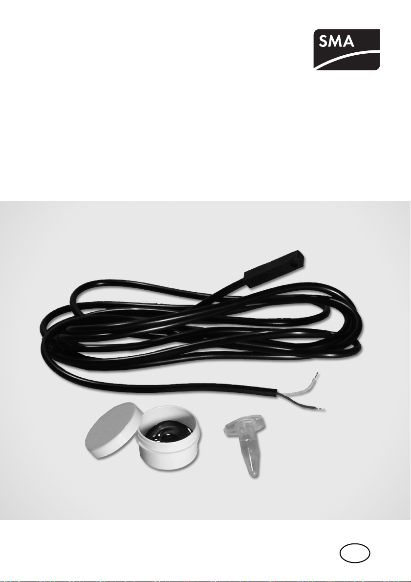
PT100M-NR
Installation Guide
PT100MNR-IEN083510 | 98-0017210 | Version 1.0
EN
Page 2

Page 3

SMA Solar Technology AG Table of Contents
Table of Contents
1 Notes on this Manual. . . . . . . . . . . . . . . . . . . . . . . . . . . . . . 5
1.1 Validity . . . . . . . . . . . . . . . . . . . . . . . . . . . . . . . . . . . . . . . . . . . . 5
1.2 Target Group . . . . . . . . . . . . . . . . . . . . . . . . . . . . . . . . . . . . . . . 5
1.3 Symbols Used . . . . . . . . . . . . . . . . . . . . . . . . . . . . . . . . . . . . . . . 5
2 Safety . . . . . . . . . . . . . . . . . . . . . . . . . . . . . . . . . . . . . . . . . . 6
2.1 Appropriate Usage. . . . . . . . . . . . . . . . . . . . . . . . . . . . . . . . . . . 6
2.2 Safety Instructions . . . . . . . . . . . . . . . . . . . . . . . . . . . . . . . . . . . . 6
3 Unpacking. . . . . . . . . . . . . . . . . . . . . . . . . . . . . . . . . . . . . . . 7
3.1 Packing List . . . . . . . . . . . . . . . . . . . . . . . . . . . . . . . . . . . . . . . . . 7
3.2 Identifying the Module Temperature Sensor. . . . . . . . . . . . . . . . 7
4 Installation and Electrical Connection. . . . . . . . . . . . . . . . . 7
4.1 Cabling Recommendations. . . . . . . . . . . . . . . . . . . . . . . . . . . . . 8
4.2 Selecting Where to Install. . . . . . . . . . . . . . . . . . . . . . . . . . . . . . 8
4.3 Installing the Sensor . . . . . . . . . . . . . . . . . . . . . . . . . . . . . . . . . . 9
4.4 Connection Overview . . . . . . . . . . . . . . . . . . . . . . . . . . . . . . . . . 9
4.5 Connecting the Sensor to the Sunny SensorBox . . . . . . . . . . . . . 9
4.6 Connecting the Sensor to the Sunny Boy Control Plus . . . . . . . 10
4.7 Connecting the Sensor to the Sunny Central . . . . . . . . . . . . . . 11
5 Configuration . . . . . . . . . . . . . . . . . . . . . . . . . . . . . . . . . . . 12
5.1 Configuring the Sensor with the Sunny Boy Control Plus . . . . . 12
5.2 Configuring the Sensor with the Sunny Central Control . . . . . . 12
6 Decommissioning . . . . . . . . . . . . . . . . . . . . . . . . . . . . . . . . 13
6.1 Uninstalling the Sensor . . . . . . . . . . . . . . . . . . . . . . . . . . . . . . . 13
6.2 Disposing of the Sensor . . . . . . . . . . . . . . . . . . . . . . . . . . . . . . 13
7 Technical Data . . . . . . . . . . . . . . . . . . . . . . . . . . . . . . . . . . 13
Installation Guide PT100MNR-IEN083510 3
Page 4

Table of Contents SMA Solar Technology AG
8 Accessories . . . . . . . . . . . . . . . . . . . . . . . . . . . . . . . . . . . . . 13
9 Contact . . . . . . . . . . . . . . . . . . . . . . . . . . . . . . . . . . . . . . . . 14
4 PT100MNR-IEN083510 Installation Guide
Page 5
SMA Solar Technology AG Notes on this Manual
1 Notes on this Manual
This manual describes how to install and commission the module temperature sensor. Store this
manual where it will be accessible at all times.
1.1 Validity
This manual is valid for the PT100M-NR upgrade kit.
1.2 Target Group
This manual is for qualified personnel.
1.3 Symbols Used
The following types of safety instructions and general information appear in this document as
described below:
DANGER!
DANGER indicates a safety instruction which, if not followed, will result in certain death or
serious injury.
WARNING!
WARNING indicates a safety instruction which, if not followed, could result in death or
serious injury.
CAUTION!
CAUTION indicates a safety instruction which, if not followed, could result in minor or
moderate injury.
ATTENTION!
ATTENTION indicates a safety instruction which, if not followed, could result in damage to
property.
Information
'Information' provides valuable tips for the optimal operation of your product.
Installation Guide PT100MNR-IEN083510 5
Page 6

Safety SMA Solar Technology AG
2 Safety
2.1 Appropriate Usage
The PT100M temperature sensor is a module temperature sensor. It consists of a PT100 measurement
resistor which is embedded in a plastic pipe. The measuring range of the module temperature sensor
is between -20 °C and +110 °C.
To pro ces s th e am bie nt d ata , the se nso r mu st b e co nne cte d to the Sunny Boy Control Plus or the Sunny
Central Control.
The sensor is only suitable for use with original SMA accessories or with accessories recommended
by SMA Solar Technology AG.
Appropriate usage also includes observing all further documentation relating to this device and its
components.
2.2 Safety Instructions
ATTENTION!
Damage to the sensors as a result of incorrect connection to the Sunny Boy
Control Plus or Sunny Central Control.
The Sunny Boy Control installation guide and the Sunny Central wiring diagram provided
must be used for establishing the electrical connections and connectors.
ATTENTION!
Destruction of the PV system by a lightning strike.
All devices installed on a rooftop must be integrated into the existing lightning protection
of the PV system.
Overvoltage protector
Protect your PV system components against overvoltage from outside by connecting the
sensors to an overvoltage protector. For using the sensors with the Sunny Central Control,
the corresponding overvoltage protectors can be ordered as an option from Sunny
Central.
6 PT100MNR-IEN083510 Installation Guide
Page 7

SMA Solar Technology AG Unpacking
3 Unpacking
3.1 Packing List
PT100M-NR
A
A 1 PT100M (module temperature sensor with 2.5 m cable)
B 1 Thermally conductive adhesive (protective gloves, hardener and binder)
C 2 Adhesive tape strips
B
C
3.2 Identifying the Module Temperature Sensor
The module temperature sensor can be identified by measuring the measurement resistance. The
nominal resistance equals R0 =100 Ω (at 0 degrees).
4 Installation and Electrical Connection
The PT100M module temperature sensor can be connected to the Sunny Boy Control Plus, the Sunny
Central or the Sunny SensorBox. Take into account the prefabricated cable length of 2.5 m. If the
cable length is insufficient, you can extend it using a junction box, for example over a 2 or 4-wire
system.
2-wire system
When connecting the temperature sensor in a
2-wir e syst em, the cable r esist ance is includ ed in
the measurement. Depending on the cable
length, this can lead to inaccuracies when
measuring.
The 2-wire system should therefore only be used with short cable lengths (maximum 3 m)
or where the necessary degree of measuring accuracy is not as high. In order to improve
the measuring accuracy, the use of a 4-wire system is recommended.
Installation Guide PT100MNR-IEN083510 7
Page 8

Installation and Electrical Connection SMA Solar Technology AG
4-wire system
To offset measuring errors which occur as a
result of cable resistance, connect the
temperature sensor via a 4-wire system. This
type of connection ensures the current feed and
voltage measurement are performed by separate pair cables. The cable length must not
exceed 30 m.
Protect the connection interfaces against weather conditions.
When extending the sensor cable, protect the connection interface against weather
conditions (e.g. by using a junction box or terminal box).
4.1 Cabling Recommendations
The cable length and quality will affect the signal quality. To achieve a good quality signal, observe
the following cabling instructions:
Outdoors
For outdoors, use a cable with the following basic properties.
• Cross-section: min. 4 x 0.25 mm
•UV-resistant
We recommend the following cable types:
• Lapp cable: Unitronic S-LifY11Y 4 x 0.34 mm
• UL-listed Lapp cable: UNITRONIC S-LifY11Y 4 x 0.34 mm², order no.: 7038 865
Indoors
If you protect the cable against UV radiation for use outdoors by means of a suitable cable channel,
you can also use a non-UV-resistant (indoor) cable with the basic properties mentioned above.
We recommend the following cable types:
• Lapp cable: Unitronic LiYY 4 x 0.25 mm
• UL-listed Lapp cable: UNITRONIC LiYY UL/CSA 4 x AWG22/7, order no.: 0022 604
• Helukabel: TRONIC LiYY 4 x 0.25 mm
2
, min. 4 x AWG 24
2
, order no.: 7038 861
2
, order no.: 0028 304
2
, order no.: 18031
4.2 Selecting Where to Install
Consider the following points when selecting where to install:
• Select a solar cell which is never in the shade during the day.
• The module temperature sensor is fixed to the rear.
• Take into account the prefabricated cable length of 2.5 m.
8 PT100MNR-IEN083510 Installation Guide
Page 9

SMA Solar Technology AG Installation and Electrical Connection
4.3 Installing the Sensor
CAUTION!
Burns due to contact with the thermally conductive adhesive
• Wear appropriate protective clothing, gloves and goggles when working on the
sensor.
• Avoid contact with the skin, mucous membranes and eyes.
• Follow the safety precautions and instructions from the manufacturer of the thermally
conductive adhesive.
Thermally conductive adhesive
Mix the thermally conductive adhesive according to the manufacturer's instructions. When
processing, follow the processing and setting times specified by manufacturer.
1. Take into account the sensor cable length when determining where to install.
2. Clean the installation site.
3. Prepare the thermally conductive adhesive according to the manufacturer's instructions.
4. Af fix the mod ule tem per atu re s ens or t o the low er s ide
of a solar cell using the thermally conductive
adhesive provided.
5. Affix the module temperature sensor and the cable to
the lower side of the solar cell using adhesive tape
strips.
6. The adhesive tape strips can be removed once the
thermally conductive adhesive has set.
☑ The module temperature sensor is now installed.
4.4 Connection Overview
Wire color Color allocation
Red The sensor wire can be allocated as desired. However, when using a 4-wire
White
system, the connection allocations should be observed.
4.5 Connecting the Sensor to the Sunny SensorBox
Refer to the Sunny SensorBox installation guide when configuring and connecting the sensor to the
Sunny SensorBox. You can download the current installation guide from the download page at
www.SMA.de/en or obtain it via the usual sales channels.
Installation Guide PT100MNR-IEN083510 9
Page 10

Installation and Electrical Connection SMA Solar Technology AG
4.6 Connecting the Sensor to the Sunny Boy Control Plus
The sensor is connected to the analog input port (ANALOG IN) of the Sunny Boy Control Plus using
a 2 or 4-wire system.
Protect the connection interfaces against weather conditions.
When extending the sensor cable, protect the connection interface against weather
conditions (e.g. by using a junction box or terminal box).
Connecting the sensors using a connection terminal block
To connect the sensors to the Sunny Boy Control Plus, use the 25-pin connection terminal
block (see section 8 "Accessories" (page13)).
4-wire system
The AIN-7 and AIN-8 analog input ports have been configured for a 4-wire system with PT100
resistance. The supply currents required for this are provided by the Sunny Boy Control Plus. The
sensor connection wires are duplicated in the immediate vicinity of the sensor.
Connecting the PT100 module temperature sensor to "AIN-7" in a 4-wire system
Original wire - red PIN 11 (PT100-I1+)
Duplicated wire - red PIN 9 (AIN-7+)
Duplicated wire - white PIN 20 (AIN-7-)
Original wire - white PIN 22 (PT100-I1-)
Connecting the PT100 module temperature sensor to "AIN-8" in a 4-wire system
Original wire - red PIN 12 (PT100-I2+)
Duplicated wire - red PIN 10 (AIN-8+)
Duplicated wire - white PIN 21 (AIN-8-)
Original wire - white PIN 23 (PT100-I2-)
2-wire system
Connecting the PT100 module temperature sensor to "AIN-7" in a 2-wire system
Red Bridge PIN 9 (AIN-7+) wi th PIN 11 (PT100-I1+)
White Bridge PIN 20 (AIN-7-) and PIN 22 (PT100-I1-)
Connecting the PT100 module temperature sensor to "AIN-8" in a 2-wire system
Red Bridge PIN 10 (AIN-8+) with PIN 12
(PT100-I2+)
White Bridge PIN 21 (AIN-8-) with PIN 23 (PT100-I2-)
10 PT100MNR-IEN083510 Installation Guide
Page 11

SMA Solar Technology AG Installation and Electrical Connection
4.7 Connecting the Sensor to the Sunny Central
The sensor is connected to the Sunny Central using the Z5-X5 terminal strips.
Protect the connection interfaces against weather conditions.
When extending the sensor cable, protect the connection interface against weather
conditions (e.g. by using a junction box or terminal box).
Realizing the electrical connection
The Sunny Central wiring diagram provided must be used for establishing the electrical
connections and connectors.
4-wire system
The sensor connection wires are duplicated in the immediate vicinity of the sensor.
Connecting the PT100 module temperature sensor to "=Z5-X5" in a 4-wire system
Original wire - white Terminal 1
Duplicated wire - white Terminal 2
Original wire - red Terminal 3
Duplicated wire - red Terminal 4
2-wire system
Connecting the PT100 module temperature sensor to "=Z5-X5" in a 2-wire system
Red Bridge terminal 1 with terminal 2
White Bridge terminal 3 with terminal 4
or
Connecting the PT100 module temperature sensor to "=Z5-X5" in a 2-wire system
Red Terminal 5
White Terminal 6
or
Connecting the PT100 module temperature sensor to "=Z5-X5" in a 2-wire system
Red Terminal 7
White Terminal 8
Installation Guide PT100MNR-IEN083510 11
Page 12

Configuration SMA Solar Technology AG
5 Configuration
Configuring the Sunny Boy Control Plus or Sunny Central Control
Please refer to the Sunny Boy Control Plus user manual for the configuration. In the case of
the Sunny Central Control, the configuration is described in the Sunny Central user manual.
5.1 Configuring the Sensor with the Sunny Boy Control Plus
To suitably configure the Sunny Boy Control Plus for the connected module temperature sensor,
proceed as follows:
1. Log in to the Sunny Boy Control Plus as the installer.
2. Select the "Settings > Plus I/O > Analog In" menu option in the Sunny Boy Control Plus.
3. Select the input port that is to be configured:
AIN-7 (PT100)
or
AIN-8 (PT100)
4. Under "Function", select the desired temperature unit (e.g. °C).
5. Under "Name", enter the desired sensor name (e.g. ModSens).
☑ The sensor is now configured.
5.2 Configuring the Sensor with the Sunny Central Control
To suitably configure the Sunny Central Control for the connected temperature sensor module,
proceed as follows:
1. Log in to the Sunny Central Control as the installer.
2. Select the "Settings > Connections > Analog In" menu option in the Sunny Boy Control.
3. Select the input port that is to be configured.
4. Under "Function", select the desired temperature unit (e.g. °C).
5. Under "Name", enter the desired sensor name (e.g. module temperature sensor ).
☑ The sensor is now configured. The gain and offset do not require calculating.
12 PT100MNR-IEN083510 Installation Guide
Page 13

SMA Solar Technology AG Decommissioning
6 Decommissioning
6.1 Uninstalling the Sensor
1. Reset the configuration of the sensor in the communication device.
2. Detach the sensor cable from the communication device.
ATTENTION!
Damage to the solar cell due to detaching the module temperature sensor
Sensors should not be removed once affixed as this could cause damage to the solar cell.
The sensor cannot be reused.
• Cut the sensor cable directly from the sensor.
☑ The sensor is now uninstalled.
6.2 Disposing of the Sensor
At the end of the service life of the PV system, dispose of the sensor in accordance with the disposal
regulations for electronic waste applicable at the installation site at that time. Alternatively, send it
back to SMA Solar Technology with shipping costs paid by sender, and labeled
"ZUR ENTSORGUNG" ("for disposal")
7 Technical Data
General data
Measurement resistor PT100
Installing the Device outdoors
Protection rating IP62
Connection cable
Connection cable pre-configured cable length of 2.5 m.
Measured values
Tolerance maximum ± 0.7 °C (class B)
Measuring range -20 °C to +110 °C
Warranty, Certificates and Permits
Warranty 2 years
8 Accessories
Description SMA order number
Analog IN connection
terminal block
Installation Guide PT100MNR-IEN083510 13
25-pin, D-Sub plug for Sunny Boy Control Plus
(incl. 1:1 cable, 25-pin D-Sub, bushing/plug,
length 0.5m)
SBCOP-ANA-KIT
Page 14

Contact SMA Solar Technology AG
9 Contact
If you have technical problems concerning our products, contact our Service Line. We need the
following information to provide you with the necessary assistance:
• Sensor model
•Communication device
• Measured values
SMA Solar Technology AG
Sonnenallee 1
34266 Niestetal, Germany
www.SMA.de
Serviceline
Inverters: +49 561 9522 1499
Communication: +49 561 9522 2499
Fax: +49 561 9522 4699
E-Mail: serviceline@SMA.de
14 PT100MNR-IEN083510 Installation Guide
Sunny Central
SMA Solar Technology AG
Sonnenallee 1
34266 Niestetal, Germany
Tel. +49 561 9522 299
Fax +49 561 9522 3299
SunnyCentral.Service@SMA.de
www.SMA.de
Page 15

SMA Solar Technology AG Legal Restrictions
The information contained in this document is the property of SMA Solar Technology AG. Publishing its content, either partially or
in full, requires the written permission of SMA Solar Technology AG. Any internal company copying of the document for the
purposes of evaluating the product or its correct implementation is allowed and does not require permission.
Exclusion of liability
The general terms and conditions of delivery of SMA Solar Technology AG shall apply.
The content of these documents is continually checked and amended, where necessary. However, discrepancies cannot be
excluded. No guarantee is made for the completeness of these documents. The latest version is available online at www.SMA.de
or from the usual sales channels.
Guarantee or liability claims for damages of any kind are excluded if they are caused by one or more of the following:
• Damages during transportation
• Improper or inappropriate use of the product
• Operating the product in an unintended environment
• Operating the product whilst ignoring relevant, statutory safety regulations in the deployment location
• Ignoring safety warnings and instructions contained in all documents relevant to the product
• Operating the product under incorrect safety or protection conditions
• Altering the product or supplied software without authority
• The product malfunctions due to operating attached or neighboring devices beyond statutory limit values
• In case of unforeseen calamity or force majeure
The use of supplied software produced by SMA Solar Technology AG is subject to the following conditions:
• SMA Solar Technology AG rejects any liability for direct or indirect damages arising from the use of software developed by
SMA Solar Technology AG. This also applies to the provision or non-provision of support activities.
• Supplied software not developed by SMA Solar Technology AG is subject to the respective licensing and liability agreements
of the manufacturer.
SMA Factory Warranty
The current guarantee conditions come enclosed with your device. These are also available online at www.SMA.de and can be
downloaded or are available on paper from the usual sales channels if required.
Trademarks
All trademarks are recognized even if these are not marked separately. Missing designations do not mean that a product or brand
is not a registered trademark.
The Bluetooth
Solar Technology is under license.
SMA Solar Technology AG
Sonnenallee 1
34266 Niestetal
Germany
Tel. +49 561 9522-0
Fax +49 561 9522-100
www.SMA.de
E-Mail: info@SMA.de
© 2004 to 2009 SMA Solar Technology AG. All rights reserved
®
wor d mark an d logos a re regis tered tr ademark s owned b y Blueto oth S IG, In c. an d any u se of s uch mark s by SMA
Installation Guide PT100MNR-IEN083510 15
Page 16

SMA Solar Technology AG
www.SMA.de
Sonnenallee 1
34266 Niestetal, Germany
Tel.: +49 561 9522 4000
Fax: +49 561 9522 4040
E-Mail: Vertrieb@SMA.de
Freecall: 0800 SUNNYBOY
Freecall: 0800 78669269
 Loading...