

Page 1
Operating Manual
POWER PLANT CONTROLLER
PPC-BE-P7-en-13 | 98-113900.02 | Version 1.3 ENGLISH
Page 2

Legal Provisions SMA Solar Technology AG
Legal Provisions
The information contained in this document is the property of SMA Solar Technology AG. Publishing its content, either
partially or in full, requires the written permission of SMA Solar Technology AG. Any internal company copying of the
document for the purposes of evaluating the product or its correct implementation is allowed and does not require
permission.
SMA Warranty
You can download the current warranty conditions from the Internet at www.SMA-Solar.com.
Trademarks
All trademarks are recognized, even if not explicitly identified as such. A lack of identification does not mean that a
product or symbol is not trademarked.
The BLUETOOTH
marks by SMA Solar Technology AG is under license.
®
Modbus
is a registered trademark of Schneider Electric and is licensed by the Modbus Organization, Inc.
QR Code is a registered trademark of DENSO WAVE INCORPORATED.
®
Phillips
Torx
and Pozidriv® are registered trademarks of Phillips Screw Company.
®
is a registered trademark of Acument Global Technologies, Inc.
®
word mark and logos are registered trademarks owned by Bluetooth SIG, Inc. and any use of these
SMA Solar Technology AG
Sonnenallee 1
34266 Niestetal
Germany
Tel. +49 561 9522-0
Fax +49 561 9522-100
www.SMA.de
E-mail: info@SMA.de
© 2004 to 2015 SMA Solar Technology AG. All rights reserved.
2 PPC-BE-P7-en-13 Operating Manual
Page 3

SMA Solar Technology AG Table of Contents
Table of Contents
1 Information on this Document. . . . . . . . . . . . . . . . . . . . . . . . . . . . . . . . . . . . . . . . . . . . . . . . . . . . . 5
2 Safety . . . . . . . . . . . . . . . . . . . . . . . . . . . . . . . . . . . . . . . . . . . . . . . . . . . . . . . . . . . . . . . . . . . . . . . . 7
2.1 Intended Use . . . . . . . . . . . . . . . . . . . . . . . . . . . . . . . . . . . . . . . . . . . . . . . . . . . . . . . . . . . . . . . . . . . . . . . . . 7
2.2 Safety Information . . . . . . . . . . . . . . . . . . . . . . . . . . . . . . . . . . . . . . . . . . . . . . . . . . . . . . . . . . . . . . . . . . . . . 8
3 Product Overview . . . . . . . . . . . . . . . . . . . . . . . . . . . . . . . . . . . . . . . . . . . . . . . . . . . . . . . . . . . . . 10
3.1 System Overview . . . . . . . . . . . . . . . . . . . . . . . . . . . . . . . . . . . . . . . . . . . . . . . . . . . . . . . . . . . . . . . . . . . . . 10
3.2 Design of the Product . . . . . . . . . . . . . . . . . . . . . . . . . . . . . . . . . . . . . . . . . . . . . . . . . . . . . . . . . . . . . . . . . . 11
3.3 Operating and Display Elements of the Control Unit . . . . . . . . . . . . . . . . . . . . . . . . . . . . . . . . . . . . . . . . . . 11
3.4 User Interface of the Power Plant Controller. . . . . . . . . . . . . . . . . . . . . . . . . . . . . . . . . . . . . . . . . . . . . . . . . 12
3.4.1 Design of the User Interface . . . . . . . . . . . . . . . . . . . . . . . . . . . . . . . . . . . . . . . . . . . . . . . . . . . . . . . . . . . . . . .12
3.4.2 "My System" . . . . . . . . . . . . . . . . . . . . . . . . . . . . . . . . . . . . . . . . . . . . . . . . . . . . . . . . . . . . . . . . . . . . . . . . . . .13
3.4.3 "PPC" . . . . . . . . . . . . . . . . . . . . . . . . . . . . . . . . . . . . . . . . . . . . . . . . . . . . . . . . . . . . . . . . . . . . . . . . . . . . . . . . .14
4 Scope of Delivery. . . . . . . . . . . . . . . . . . . . . . . . . . . . . . . . . . . . . . . . . . . . . . . . . . . . . . . . . . . . . . 15
5 Mounting. . . . . . . . . . . . . . . . . . . . . . . . . . . . . . . . . . . . . . . . . . . . . . . . . . . . . . . . . . . . . . . . . . . . . 16
5.1 Requirements for Mounting. . . . . . . . . . . . . . . . . . . . . . . . . . . . . . . . . . . . . . . . . . . . . . . . . . . . . . . . . . . . . . 16
5.2 Mounting the Power Plant Controller . . . . . . . . . . . . . . . . . . . . . . . . . . . . . . . . . . . . . . . . . . . . . . . . . . . . . . 19
6 Installation . . . . . . . . . . . . . . . . . . . . . . . . . . . . . . . . . . . . . . . . . . . . . . . . . . . . . . . . . . . . . . . . . . . 21
6.1 Overview of the Connection Area . . . . . . . . . . . . . . . . . . . . . . . . . . . . . . . . . . . . . . . . . . . . . . . . . . . . . . . . 21
6.2 Connecting the Supply Voltage . . . . . . . . . . . . . . . . . . . . . . . . . . . . . . . . . . . . . . . . . . . . . . . . . . . . . . . . . . 22
6.3 Connecting Digital Inputs and Outputs. . . . . . . . . . . . . . . . . . . . . . . . . . . . . . . . . . . . . . . . . . . . . . . . . . . . . 23
6.4 Connecting Analog Inputs and Outputs . . . . . . . . . . . . . . . . . . . . . . . . . . . . . . . . . . . . . . . . . . . . . . . . . . . . 24
6.5 Connecting Network Cables and Optical Fibers . . . . . . . . . . . . . . . . . . . . . . . . . . . . . . . . . . . . . . . . . . . . . 24
7 Operation . . . . . . . . . . . . . . . . . . . . . . . . . . . . . . . . . . . . . . . . . . . . . . . . . . . . . . . . . . . . . . . . . . . . 27
7.1 Safety during Operation. . . . . . . . . . . . . . . . . . . . . . . . . . . . . . . . . . . . . . . . . . . . . . . . . . . . . . . . . . . . . . . . 27
7.2 Adjusting Network Settings on the Computer. . . . . . . . . . . . . . . . . . . . . . . . . . . . . . . . . . . . . . . . . . . . . . . . 27
7.3 Installing the Droid Sans Font on the Computer . . . . . . . . . . . . . . . . . . . . . . . . . . . . . . . . . . . . . . . . . . . . . . 27
7.4 Changing the Password . . . . . . . . . . . . . . . . . . . . . . . . . . . . . . . . . . . . . . . . . . . . . . . . . . . . . . . . . . . . . . . . 27
7.5 Changing Language and Time Settings . . . . . . . . . . . . . . . . . . . . . . . . . . . . . . . . . . . . . . . . . . . . . . . . . . . . 28
7.6 Adjusting the Device Settings . . . . . . . . . . . . . . . . . . . . . . . . . . . . . . . . . . . . . . . . . . . . . . . . . . . . . . . . . . . . 28
7.6.1 Adjusting IP Addresses of the Power Plant Controller . . . . . . . . . . . . . . . . . . . . . . . . . . . . . . . . . . . . . . . . . . . .28
7.6.2 Adjusting the Configuration of the Sunny Centrals . . . . . . . . . . . . . . . . . . . . . . . . . . . . . . . . . . . . . . . . . . . . . .29
7.6.3 Adjusting the Configuration of the Cluster Controllers and Inverter Managers. . . . . . . . . . . . . . . . . . . . . . . . .30
7.6.4 Adjusting the Configuration of the Network Analyzers . . . . . . . . . . . . . . . . . . . . . . . . . . . . . . . . . . . . . . . . . . .31
7.6.5 Adjusting the Configuration of the Power Plant Controller Slaves . . . . . . . . . . . . . . . . . . . . . . . . . . . . . . . . . . .33
7.7 Adjusting the Settings of the Modbus Server . . . . . . . . . . . . . . . . . . . . . . . . . . . . . . . . . . . . . . . . . . . . . . . . 33
7.8 Transmitting Output Values to Devices of the PV System . . . . . . . . . . . . . . . . . . . . . . . . . . . . . . . . . . . . . . . 34
7.9 Selecting the Signal Source and Adjusting the Scaling of Measured Values. . . . . . . . . . . . . . . . . . . . . . . . 34
7.10 Local Specification of Setpoints . . . . . . . . . . . . . . . . . . . . . . . . . . . . . . . . . . . . . . . . . . . . . . . . . . . . . . . . . . 37
7.11 Saving and Restoring Settings of the Power Plant Controller . . . . . . . . . . . . . . . . . . . . . . . . . . . . . . . . . . . . 37
7.12 Calling Up the System Overview . . . . . . . . . . . . . . . . . . . . . . . . . . . . . . . . . . . . . . . . . . . . . . . . . . . . . . . . . 39
7.12.1 Calling Up the Overview of the Entire System. . . . . . . . . . . . . . . . . . . . . . . . . . . . . . . . . . . . . . . . . . . . . . . . . .39
7.12.2 Retrieving the Status and Current Data of All Devices in the System. . . . . . . . . . . . . . . . . . . . . . . . . . . . . . . . .39
Operating Manual PPC-BE-P7-en-13 3
Page 4

Table of Contents SMA Solar Technology AG
8 Troubleshooting . . . . . . . . . . . . . . . . . . . . . . . . . . . . . . . . . . . . . . . . . . . . . . . . . . . . . . . . . . . . . . .40
8.1 Calling up Information on Software Version and Service-Relevant Information. . . . . . . . . . . . . . . . . . . . . . 40
8.2 Calling-Up and Acknowledging Error, Warning and Event Messages . . . . . . . . . . . . . . . . . . . . . . . . . . . . 40
8.3 Errors and Warnings . . . . . . . . . . . . . . . . . . . . . . . . . . . . . . . . . . . . . . . . . . . . . . . . . . . . . . . . . . . . . . . . . . 40
8.4 Corrective Measures in the Event of Disturbance. . . . . . . . . . . . . . . . . . . . . . . . . . . . . . . . . . . . . . . . . . . . . 41
9 Maintenance . . . . . . . . . . . . . . . . . . . . . . . . . . . . . . . . . . . . . . . . . . . . . . . . . . . . . . . . . . . . . . . . . .46
9.1 Maintenance and Replacement Intervals. . . . . . . . . . . . . . . . . . . . . . . . . . . . . . . . . . . . . . . . . . . . . . . . . . . 46
9.2 Checking the Mounting Location . . . . . . . . . . . . . . . . . . . . . . . . . . . . . . . . . . . . . . . . . . . . . . . . . . . . . . . . . 46
9.3 Switching the Power Plant Controller On and Off . . . . . . . . . . . . . . . . . . . . . . . . . . . . . . . . . . . . . . . . . . . . 46
9.4 Checking the Enclosure and Enclosure Interior . . . . . . . . . . . . . . . . . . . . . . . . . . . . . . . . . . . . . . . . . . . . . . 47
9.5 Replacing the SD Memory Card of the Power Plant Controller . . . . . . . . . . . . . . . . . . . . . . . . . . . . . . . . . . 47
10 Decommissioning . . . . . . . . . . . . . . . . . . . . . . . . . . . . . . . . . . . . . . . . . . . . . . . . . . . . . . . . . . . . . .48
10.1 Disassembling the Power Plant Controller . . . . . . . . . . . . . . . . . . . . . . . . . . . . . . . . . . . . . . . . . . . . . . . . . . 48
10.2 Disposing of the Power Plant Controller. . . . . . . . . . . . . . . . . . . . . . . . . . . . . . . . . . . . . . . . . . . . . . . . . . . . 48
11 Periodic Actions. . . . . . . . . . . . . . . . . . . . . . . . . . . . . . . . . . . . . . . . . . . . . . . . . . . . . . . . . . . . . . . .49
11.1 Cable Entry . . . . . . . . . . . . . . . . . . . . . . . . . . . . . . . . . . . . . . . . . . . . . . . . . . . . . . . . . . . . . . . . . . . . . . . . . 49
11.1.1 Inserting the Cable into the Cable Feed-Through Plate . . . . . . . . . . . . . . . . . . . . . . . . . . . . . . . . . . . . . . . . . . .49
11.1.2 Inserting the Cable in the Cable Gland. . . . . . . . . . . . . . . . . . . . . . . . . . . . . . . . . . . . . . . . . . . . . . . . . . . . . . .50
11.2 Clamp Connections . . . . . . . . . . . . . . . . . . . . . . . . . . . . . . . . . . . . . . . . . . . . . . . . . . . . . . . . . . . . . . . . . . . 51
11.2.1 Connecting Insulated Conductors to Spring-Cage Terminals. . . . . . . . . . . . . . . . . . . . . . . . . . . . . . . . . . . . . . .51
11.2.2 Connecting the Shield Contact of the Cable Using a Shield Clamping Saddle . . . . . . . . . . . . . . . . . . . . . . . .52
11.2.3 Installing Network Cables to the RJ45 Keystone Pin Connector . . . . . . . . . . . . . . . . . . . . . . . . . . . . . . . . . . . .52
11.3 Settings on the User Interface . . . . . . . . . . . . . . . . . . . . . . . . . . . . . . . . . . . . . . . . . . . . . . . . . . . . . . . . . . . 54
11.3.1 Logging Into the User Interface . . . . . . . . . . . . . . . . . . . . . . . . . . . . . . . . . . . . . . . . . . . . . . . . . . . . . . . . . . . . .54
11.3.1.1 Logging In at the Touch Display . . . . . . . . . . . . . . . . . . . . . . . . . . . . . . . . . . . . . . . . . . . . . . . . . . . . . . . . . . . . . 54
11.3.1.2 Logging In on the Computer . . . . . . . . . . . . . . . . . . . . . . . . . . . . . . . . . . . . . . . . . . . . . . . . . . . . . . . . . . . . . . . . 54
11.3.2 Logging Out of the User Interface . . . . . . . . . . . . . . . . . . . . . . . . . . . . . . . . . . . . . . . . . . . . . . . . . . . . . . . . . . .54
12 Technical Data. . . . . . . . . . . . . . . . . . . . . . . . . . . . . . . . . . . . . . . . . . . . . . . . . . . . . . . . . . . . . . . . .55
13 Appendix. . . . . . . . . . . . . . . . . . . . . . . . . . . . . . . . . . . . . . . . . . . . . . . . . . . . . . . . . . . . . . . . . . . . .57
13.1 Structure of the System Network . . . . . . . . . . . . . . . . . . . . . . . . . . . . . . . . . . . . . . . . . . . . . . . . . . . . . . . . . 57
13.2 Principle of the Communication Network. . . . . . . . . . . . . . . . . . . . . . . . . . . . . . . . . . . . . . . . . . . . . . . . . . . 57
13.3 Scaling of the Analog Measuring Channels . . . . . . . . . . . . . . . . . . . . . . . . . . . . . . . . . . . . . . . . . . . . . . . . 57
13.4 Output Value Specification Under Fault Conditions. . . . . . . . . . . . . . . . . . . . . . . . . . . . . . . . . . . . . . . . . . . 59
13.5 Directive for Secure Passwords . . . . . . . . . . . . . . . . . . . . . . . . . . . . . . . . . . . . . . . . . . . . . . . . . . . . . . . . . . 59
13.6 Type Label . . . . . . . . . . . . . . . . . . . . . . . . . . . . . . . . . . . . . . . . . . . . . . . . . . . . . . . . . . . . . . . . . . . . . . . . . . 59
14 Contact. . . . . . . . . . . . . . . . . . . . . . . . . . . . . . . . . . . . . . . . . . . . . . . . . . . . . . . . . . . . . . . . . . . . . . .61
4 PPC-BE-P7-en-13 Operating Manual
Page 5
SMA Solar Technology AG 1 Information on this Document
'$1*(5
:$5 1,1*
&$87,21
/05*$&
1 Information on this Document
Validity
This document is valid for the following device types from production version P7 and software version 01.03.20.R.:
• Power Plant Controller (PPC-10)
The production version is indicated on the type label.
You can read off the software version via the user interface.
Target Group
The activities described in this document must only be performed by qualified persons. Qualified persons must have the
following skills:
• Knowledge of how to deal with the dangers and risks associated with installing and using electrical devices
• Training in the installation and configuration of IT systems
• Knowledge of all applicable standards and directives
• Knowledge of operation and control of PV power plants on medium-voltage grids and high-voltage grids
• Knowledge of and compliance with this document and all safety information
Additional Information
Links to additional information can be found at www.SMA-Solar.com:
Document title Document type
Interface for Modbus Communication SUNNY WEBBOX / SC-COM Modbus
Interface
Technical Description
Symbols
Symbol Explanation
Indicates a hazardous situation which, if not avoided, will result in death or serious injury
Indicates a hazardous situation which, if not avoided, can result in death or serious injury
Indicates a hazardous situation which, if not avoided, can result in minor or moderate injury
Indicates a situation which, if not avoided, can result in property damage
Information that is important for a specific topic or goal, but is not safety-relevant
☐ Indicates a requirement for meeting a specific goal
☑ Desired result
✖ A problem that might occur
Operating Manual PPC-BE-P7-en-13 5
Page 6

1 Information on this Document SMA Solar Technology AG
Typographies
Typography Use Example
bold • Display messages
• Elements on a user interface
• Parameters
•Terminals
•Slots
• Elements to be selected or entered
> • Connects several elements to be selected • Select PV system > Detection.
[Button/Key] • Button or key to be selected or pressed • Select [Start detection].
• Select the parameter
ExlTrfErrEna and set to Off.
• Select the tab Parameters.
Nomenclature
Complete designation Designation in this document
SMA Power Plant Controller Power Plant Controller
SMA Cluster Controller Cluster Controller
Sunny Central CP XT Sunny Central
The Sunny Centrals and Cluster Controllers connected to the Power Plant Controller are referred to as devices.
Abbreviations
Abbreviation Designation Explanation
AC Alternating Current ‒
DC Direct Current ‒
ESD Electrostatic Discharge ‒
IP Internet Protocol ‒
LAN Local Area Network ‒
LED Light-Emitting Diode ‒
PE Protective Earth Protective conductor
PV Photovoltaics ‒
SC Subscriber Connector Plug for connection via optical fiber
6 PPC-BE-P7-en-13 Operating Manual
Page 7

SMA Solar Technology AG 2 Safety
2 Safety
This section contains safety information that must be observed at all times when working on or with the product. To prevent
personal injury or property damage and to ensure long-term operation of the product, read this section carefully and
observe all safety information at all times.
2.1 Intended Use
The Power Plant Controller is a device for the automatic control of large-scale PV power plants and the implementation
of active power and reactive power setpoints in large-scale PV power plants according to grid operator specifications.
The Power Plant Controller is suitable for indoor use. The Power Plant Controller without touch display is also suitable for
outdoor use.
The Power Plant Controller is designed for industrial use.
The Power Plant Controller must only be used with supported devices:
• Sunny Central Communication Controller (SC-COM) from firmware version 1.01
• Sunny Central 2200 / Sunny Central 2500 from firmware version 1.0
• SMA Cluster Controller from firmware version 1.0
• Sunny Tripower 60 with Inverter Manager from firmware version 1.45
• Transducer and network analyzer* :
Manufacturer Model
Ardetem TRM4
Janitza UMG 604 / UMG 605
Schneider Electric ION 7550 / ION 7650 / ION 8600
Schweitzer Engineering Laboratories SEL-735
When using the network analyzer Janitza UMG 604 / UMG 605, do not operate it in the same grid segment as
the inverters connected to the Power Plant Controller, since mutual interference may occur.
Only perform work on the Power Plant Controller using the appropriate tools and in compliance with the ESD protection
regulations.
For safety reasons, it is not permitted to modify the product or install components that are not explicitly recommended or
distributed by SMA Solar Technology AG for this product. Unauthorized changes or modifications will void any warranty
claims.
Any use of the product other than that described in the Intended Use section does not qualify as appropriate.
The type labels must be permanently attached to the product.
Only use the Power Plant Controller in accordance with the information provided in the enclosed documentation. Any
other use can result in personal injury or property damage.
The enclosed documentation is an integral part of this product.
• Read and observe the documentation.
• Keep the documentation in a convenient place for future reference.
* More transducers and network analyzers are available on request.
Operating Manual PPC-BE-P7-en-13 7
Page 8

2 Safety SMA Solar Technology AG
'$1*(5
:$5 1,1*
/05*$&
2.2 Safety Information
Electric shock due to live voltage
Danger of electric shock if work is executed incorrectly or under fault conditions. This results in death or serious injury.
• Wear personal protective equipment.
• Disconnect the supply voltage before performing any work on the Power Plant Controller.
• Observe the five safety rules when disconnecting the supply voltage:
– Disconnect from voltage sources
– Ensure that the device cannot be reconnected.
– Ensure that no voltage is present
– Ground and short-circuit the device
– Cover and isolate any adjacent live components
• Wait one minute for the capacitors of the redundant electricity supply to discharge.
Electric shock due to damaged Power Plant Controller
Operating a damaged Power Plant Controller can lead to hazardous situations that result in death or serious injuries
due to electric shock.
• Only operate the Power Plant Controller when it is in perfect working order and safe to operate.
• Check the Power Plant Controller regularly for visible damage.
• Make sure that all external safety equipment is freely accessible at all times.
• Make sure that all safety equipment is in good working order.
Danger to life due to blocked escape routes
In hazardous situations, blocked escape routes can lead to death or serious injury.
• An escape route of at least 500 mm width must be available at all times. Make sure the minimum passage width
of the escape route meets local standards.
• Observe the minimum clearances when installing the Power Plant Controller.
• Do not place any objects in the escape route area.
• Remove all tripping hazards from escape routes.
Damage to the Power Plant Controller due to moisture penetration
Dust intrusion or moisture penetration can damage the Power Plant Controller or impair its functionality.
• Do not open the Power Plant Controller when humidity exceeds 95%.
• Only perform maintenance work on the Power Plant Controller when the environment is dry and free of dust.
Damage to the Power Plant Controller due to overvoltage
When overvoltage occurs, the Power Plant Controller can be damaged.
• Provide the Power Plant Controller with an external overvoltage protection.
8 PPC-BE-P7-en-13 Operating Manual
Page 9

SMA Solar Technology AG 2 Safety
/05*$&
Damage to the Power Plant Controller due to unauthorized access
If the Power Plant Controller is left unlocked, it will be freely accessible to unauthorized persons.
• Lock the Power Plant Controller after commissioning.
• Remove the key from the door lock.
• Store the keys in a safe place.
• Secure the user interface using a secure password.
• Secure your Internet connection from cyber attacks by appropriate safety measures.
Operating Manual PPC-BE-P7-en-13 9
Page 10
3 Product Overview SMA Solar Technology AG
3 Product Overview
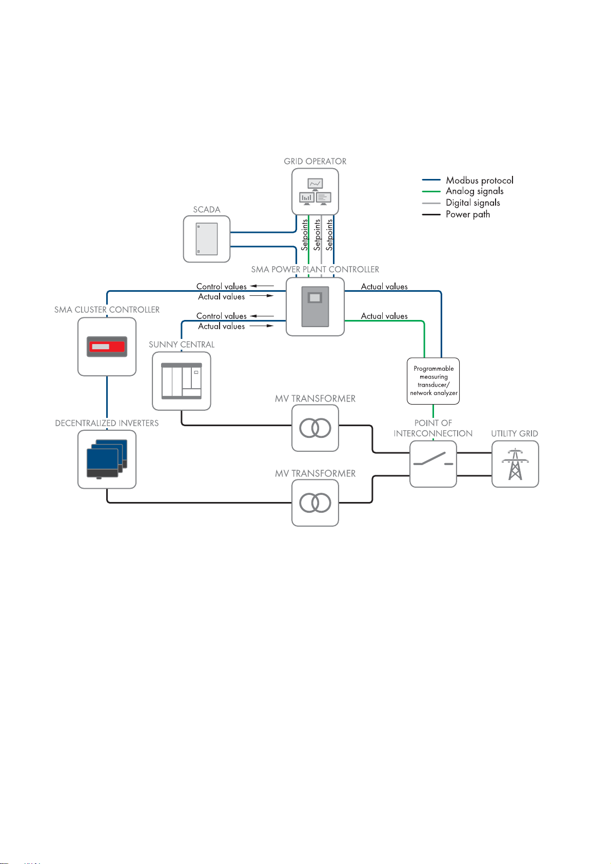
3.1 System Overview
The Power Plant Controller assumes the park management function in large PV systems. The PV system can combine both
central inverters and decentralized string inverters, which are monitored and controlled by Cluster Controllers.
Figure1: Principle of signal transfer in a PV system with Power Plant Controller
In the Power Plant Controller, the setpoints for grid management services are received and compared with the values
measured at the point of interconnection. Based on this comparison, the Power Plant Controller calculates the required
output values and transmits these values to the central inverters and the Cluster Controllers or the Inverter Manager.
The Power Plant Controller can receive setpoints digitally, analog, and via Modbus protocol. The setpoints are
transmitted by the grid operator or by a higher-level SCADA system via Modbus protocol.
The measured values that the Power Plant Controller receives are measured at the point of interconnection, processed by
a network analyzer, and transmitted to the Power Plant Controller as analog values or via Modbus protocol.
Transmission of the output values from the Power Plant Controller to central inverters, Cluster Controllers and the
Inverter Manager takes place via Modbus protocol.
10 PPC-BE-P7-en-13 Operating Manual
Page 11
SMA Solar Technology AG 3 Product Overview
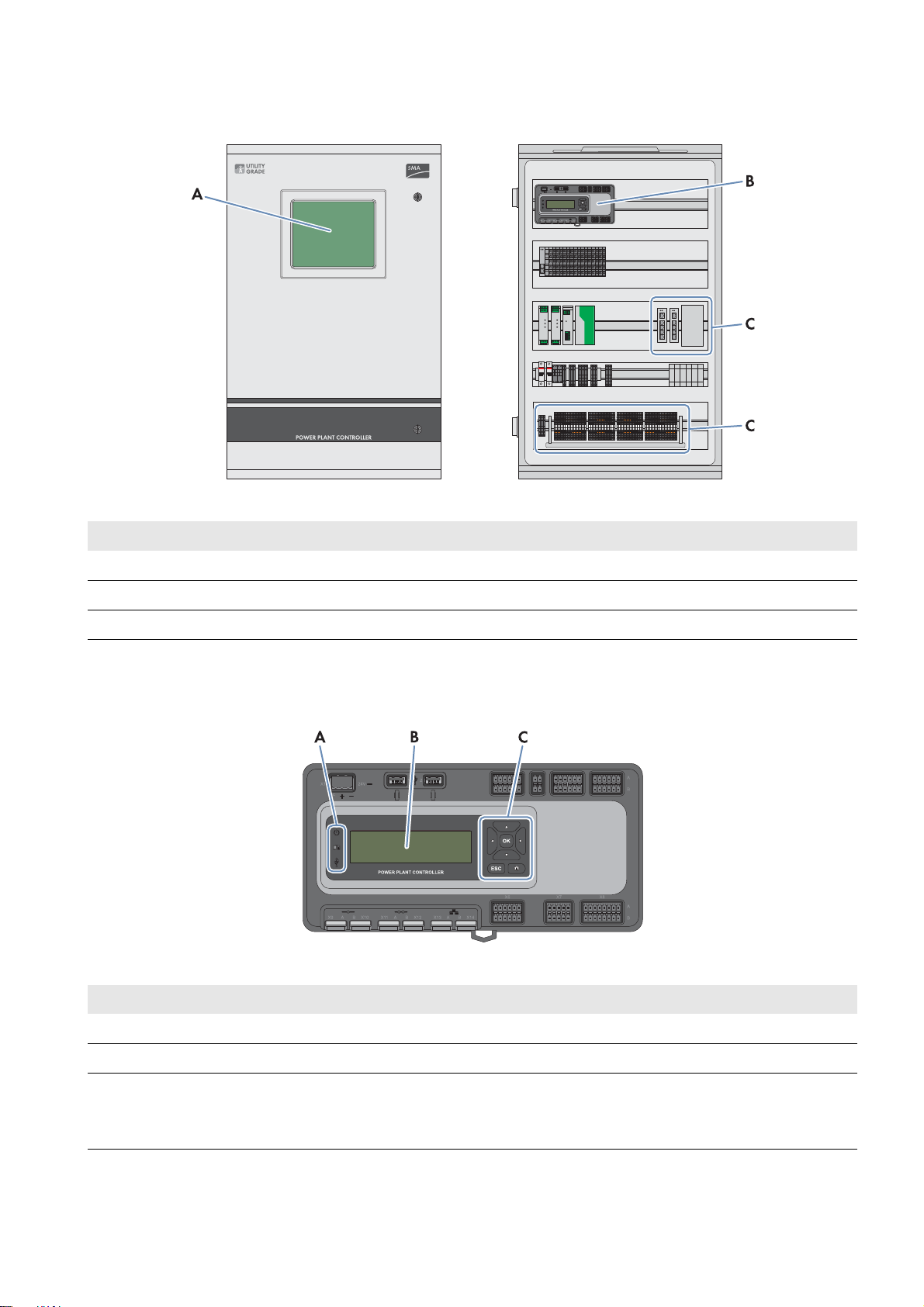
3.2 Design of the Product
Figure2: Exterior and interior views of the Power Plant Controller
Position Designation
ATouch display*
B Control unit
CConnection area
*optional
3.3 Operating and Display Elements of the Control Unit
Figure3: Operating and display elements of the control unit
Position Designation
ALEDs
BDevice display
CKeypad
The network settings of the three LAN interfaces of the Power Plant Controller can be displayed
using the info button.
Operating Manual PPC-BE-P7-en-13 11
Page 12
3 Product Overview SMA Solar Technology AG
LEDs
LED Designation Explanation
Power LED • Glowing red: The Power Plant Controller is starting.
• Glowing green: The start process has been completed.
The Power Plant Controller is working normally.
Status LED The status LED is only relevant if the start process has been
completed and the Power LED is glowing green.
• Glowing red: The Power Plant Controller shows a
disturbance.
• Glowing yellow: The Power Plant Controller shows a
warning.
• Glowing green: The Power Plant Controller is working
normally.
Data carrier status LED This LED is for service purposes.
3.4 User Interface of the Power Plant Controller
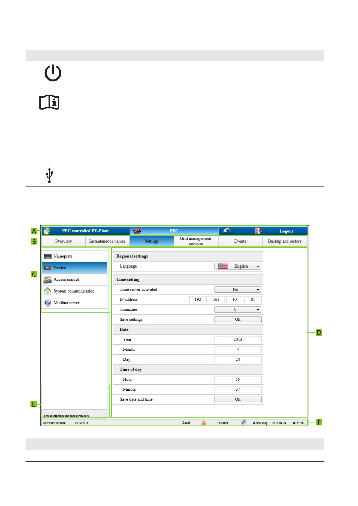
3.4.1 Design of the User Interface
Figure4: Design of the user interface (example)
Position Explanation
A First-level navigation line
12 PPC-BE-P7-en-13 Operating Manual
Page 13
SMA Solar Technology AG 3 Product Overview
Position Explanation
B Second-level navigation line (see Section3.4.3 ""PPC"", page14)
This navigation line only appears if PPC has been selected in the first-level navigation line.
C Left menu bar
The design of the menu bar depends on the selection in the second-level navigation line.
DInput area
If an entry is not plausible, it will not be accepted or the field will turn red.
E Display of the current measured values
The display can be shown or hidden by clicking on the header.
F Status bar
First-Level Navigation Line
Figure5: Design of the first-level navigation line (example)
Position Explanation
A Provides an overview of instantaneous values for the entire PV system
B Opens the second-level navigation line which is used to make settings for the Power Plant Controller and
the connected devices
C Logs the user or installer out of the user interface
The Power Plant Controller is only protected from unauthorized access after logout.
Status bar
Figure6: Design of the status bar (example)
Position Explanation
A Current software version
B Opens the dialog to change the passwords
This icon only appears if the password is not in line with the security guidelines.
C Indicates which parameters of the Power Plant Controller are used for control:
• Local: The Power Plant Controller is using the parameters set on the user interface.
• Remote: The Power Plant Controller uses the values received through communication.
D Information on the status of the logged-in user
E Information on the current system time of the Power Plant Controller
3.4.2 "My System"
Once you have logged in to the user interface of the Power Plant Controller, the system overview opens. The designation
"My system" is used as a placeholder for the name that you give to your system.
Here you can find information on the name and total power of the PV system as well as the instantaneous values for grid
voltage, power frequency, active power and reactive power measured at the selected network analyzer.
Operating Manual PPC-BE-P7-en-13 13
Page 14

3 Product Overview SMA Solar Technology AG
For each instantaneous value, the field Active values indicates whether the default value or the redundant value is used.
3.4.3 "PPC"
Menu field Explanation
Overview Displays the number of all installed Sunny Centrals and Cluster Controllers in the entire PV system,
as well as the number of connected and inaccessible devices
Instantaneous
values
Settings In this area, the following settings can be displayed and adjusted:
Grid management
services
Provides an overview of instantaneous values of the Sunny Centrals, Cluster Controllers and
network analyzers
• Type label: provides unchanging, service-relevant information which is required if faults have
occurred
• Device: User interface language and Power Plant Controller time settings
• Access control: Passwords of the user groups
• System communication: IP addresses of Power Plant Controllers, Sunny Centrals,
Cluster Controllers and Inverter Managers as well as activating and deactivating the
communication
• Modbus server: Configuration of the Modbus server (installer mode only)
In this area, the following settings can be adjusted:
• Device table inverters: IP addresses of the Sunny Centrals and configuration of the
communication between the Sunny Centrals and the Power Plant Controller (installer mode
only)
• Device table Modbus gateways: IP addresses of the Cluster Controller and
Inverter Manager as well as configuration of the communication between these devices and
the Power Plant Controller (installer mode only)
• Device table PPC Slave: IP addresses of the Power Plant Controller slaves and the type of
slave operation as well as grouping of the slaves
• Device table Power analyzers: Configuration of the network analyzers and entry of the
corresponding IP address (installer mode only)
• Setpoint: Change of setpoint mode from Remote (Modbus protocol or analog values) to
Local (fixed setpoint) and entry of the fixed setpoints for active power and reactive power
with local setpoint transmission (installer mode only)
• Input signals: Selection and scaling of the signals sent from the point of interconnection to
the Power Plant Controller
Events Displays all the errors and warnings that have occurred
The errors and warnings are acknowledged here.
Backup and
restore
14 PPC-BE-P7-en-13 Operating Manual
Enables the current configuration of the Power Plant Controller to be saved or updated via SD
memory card
Page 15
SMA Solar Technology AG 4 Scope of Delivery
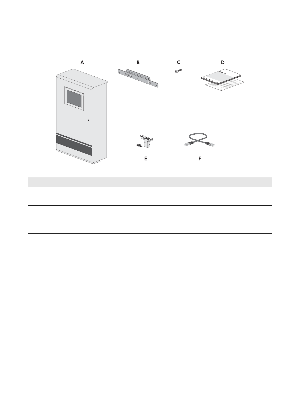
4 Scope of Delivery
Check the scope of delivery for completeness and any externally visible damage. Contact your distributor if the scope of
delivery is incomplete or damaged.
Figure7: Components included in the scope of delivery
Position Quantity Designation
A 1 Power Plant Controller
B 1 Wall mounting bracket
C2Screw
D 1 each Operating manual, circuit diagram
E4/8Keystone jack*
F 2 Patch cable*
*optional
Operating Manual PPC-BE-P7-en-13 15
Page 16

5 Mounting SMA Solar Technology AG
:$5 1,1*
5 Mounting
5.1 Requirements for Mounting
Requirements for the Mounting Location
Danger to life due to fire or explosion if mounted at an unsuitable location
Mounting the Power Plant Controller in areas with a high fire hazard can result in fire. This can result in death or serious
injury.
• Do not mount the Power Plant Controller on flammable construction materials.
• Do not mount the Power Plant Controller in areas containing highly flammable materials.
• Do not mount the Power Plant Controller in potentially explosive atmospheres.
☐ The mounting location must not be in a living or office area.
☐ The mounting location must not block any escape routes.
☐ The mounting location must be freely and safely accessible at all times without the necessity for any auxiliary
equipment (such as scaffolding or lifting platforms). Non-fulfillment of these criteria may restrict servicing.
☐ The mounting location and the mounting foundation must be suitable for the weight and dimensions of the
Power Plant Controller (see Section12 "Technical Data", page55).
☐ The ambient conditions at the mounting location must be suitable for the operation of the Power Plant Controller
(see Section12 "Technical Data", page55).
☐ The mounting location should not be exposed to direct solar irradiation.
☐ The Power Plant Controller with touch display must be mounted indoors.
☐ The Power Plant Controller must be mounted on a solid support surface.
16 PPC-BE-P7-en-13 Operating Manual
Page 17
SMA Solar Technology AG 5 Mounting
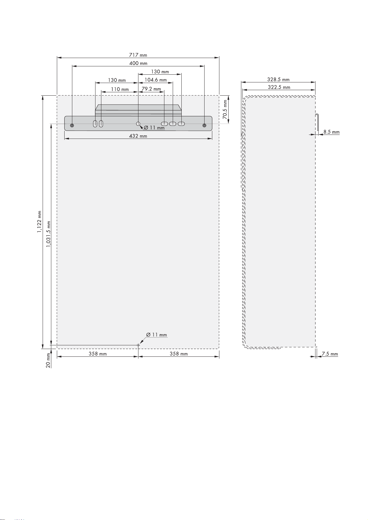
Dimensions for Mounting
Figure8: Dimensions of the Power Plant Controller
Operating Manual PPC-BE-P7-en-13 17
Page 18
5 Mounting SMA Solar Technology AG
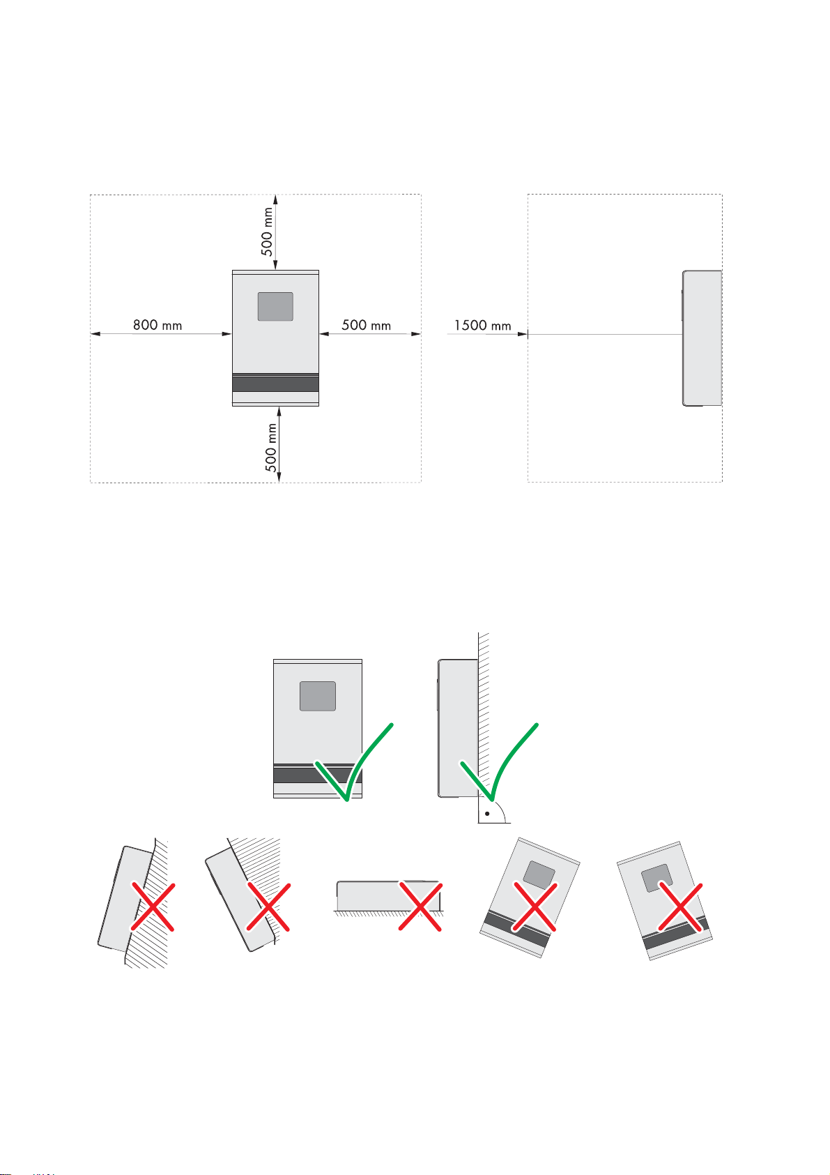
Minimum Clearances
Observing the minimum clearances allows you to easily mount, open and close the Power Plant Controller. The opening
angle of the door is 180°.
☐ Minimum clearances must be observed.
Figure9: Minimum clearances
Permitted and prohibited mounting positions:
☐ Only mount the Power Plant Controller in a permitted position.
☐ The Power Plant Controller should be mounted at eye level. This will make it easier to adjust settings on the display.
☐ The Power Plant Controller should be closed for mounting. This will prevent dust from penetrating the enclosure.
Figure10: Permitted and prohibited mounting positions
18 PPC-BE-P7-en-13 Operating Manual
Page 19
SMA Solar Technology AG 5 Mounting
&$87,21
5.2 Mounting the Power Plant Controller
Danger of crushing from falling Power Plant Controller if mounted incorrectly
The Power Plant Controller is very heavy. If inappropriately transported or mounted, the Power Plant Controller can fall
down. This can result in crushing.
• Two people are needed to transport and mount the Power Plant Controller.
• Use mounting material suitable for the support surface when mounting the Power Plant Controller.
Additionally required mounting material (not included in the scope of delivery):
☐ At least four screws suitable for the support surface and the weight of the Power Plant Controller
☐ At least four washers
☐ If required, at least four screw anchors suitable for the support surface
Procedure:
1. Align the wall mounting bracket horizontally on the wall and use it to mark the position of the drill holes. Use at least
three holes in the wall mounting bracket.
2. Drill holes at the marked positions.
3. Insert screw anchors, if necessary.
4. Attach the wall mounting bracket using appropriate screws and
washers.
5. Hook the Power Plant Controller into the wall mounting bracket.
6. Make sure that the Power Plant Controller is correctly positioned on the wall mounting bracket and can be secured
with two screws in the inside.
7. Mark the drill hole on the bottom side of the Power Plant Controller.
8. Lift the Power Plant Controller vertically out of the wall mounting bracket and place it on a suitable support surface.
9. Drill the hole at the marked position.
10. If necessary, insert the screw anchor.
11. Hook the Power Plant Controller into the wall mounting bracket.
12. Attach the Power Plant Controller to the wall using suitable screws
and washers.
Operating Manual PPC-BE-P7-en-13 19
Page 20

5 Mounting SMA Solar Technology AG
13. Open the door of the Power Plant Controller.
14. Secure the Power Plant Controller to the inside of the wall
mounting bracket using the two screws provided. Only fasten the
screws hand-tight (torque: 6 Nm).
15. Make sure that the Power Plant Controller is securely attached.
20 PPC-BE-P7-en-13 Operating Manual
Page 21
SMA Solar Technology AG 6 Installation
6 Installation
6.1 Overview of the Connection Area
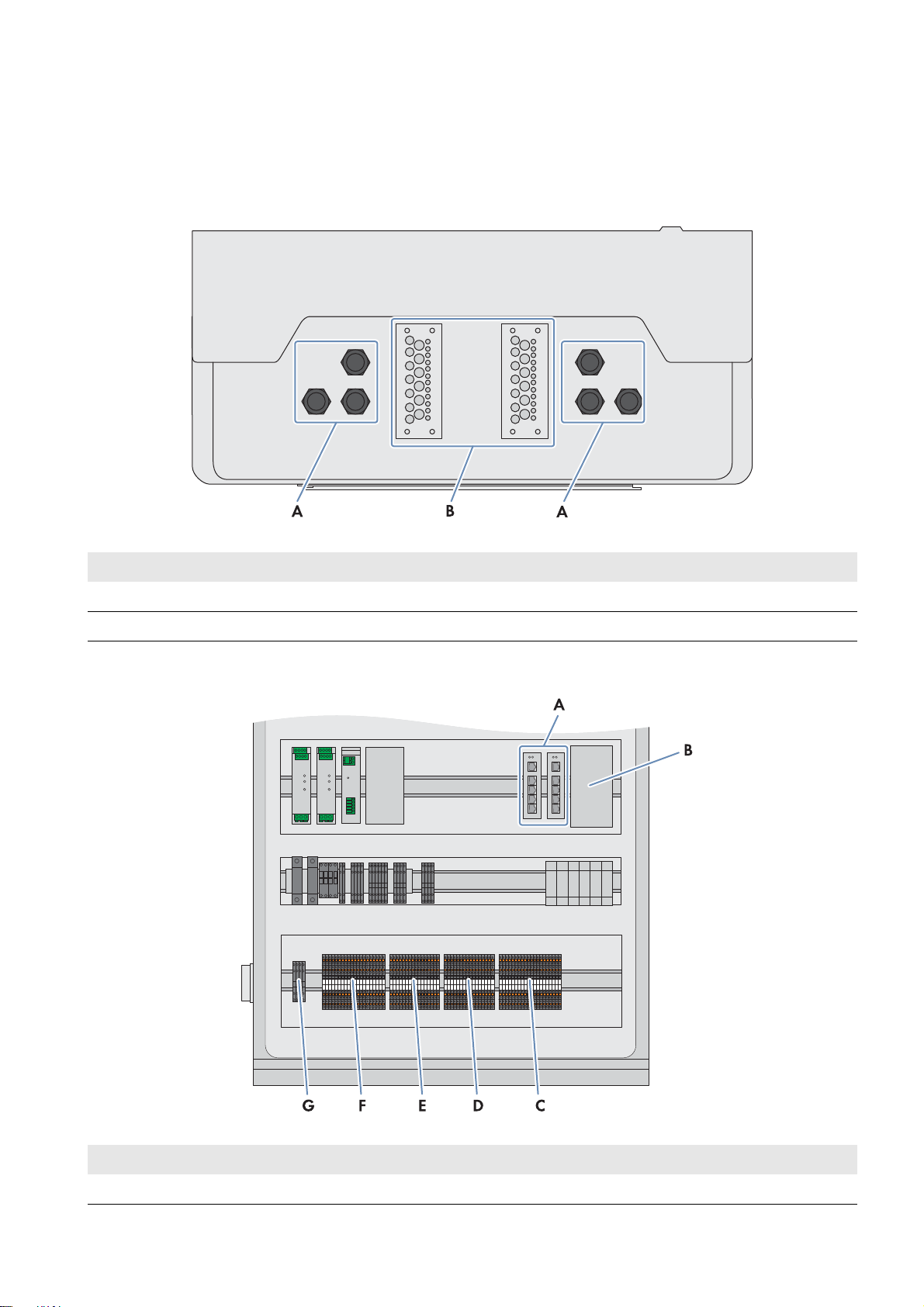
Bottom View of the Power Plant Controller
Figure11: Bottom view of the Power Plant Controller
Position Designation
A Cable glands for the connection of the pre-assembled cables
B Cable entry plates for the connection of the cables that are not pre-assembled
Terminals in the Power Plant Controller
Figure12: Terminals in the Power Plant Controller
Position Designation Explanation
A -A3 / -A4 / -A5 Network (copper)
Operating Manual PPC-BE-P7-en-13 21
Page 22
6 Installation SMA Solar Technology AG
'$1*(5
Position Designation Explanation
B -A5 Network (optical fiber)
C -X703 Analog outputs
D-X702 Analog inputs
E -X701 Digital outputs
F -X700 Digital inputs
G -X300 Voltage supply
6.2 Connecting the Supply Voltage
The Power Plant Controller is equipped with a redundant voltage supply to ensure maximum system availability, e.g. in
case of a failure of a line conductor or a DC voltage source.
Danger to life due to electric shock
Omitted disconnection device or incorrect working practices can cause electric shock. This results in death or serious
injury.
• Prior to installation work, install a disconnection device close to the Power Plant Controller. The disconnection
device must meet the requirements of local standards and directives. All-pole disconnection is recommended.
• Prior to cable connection, disconnect the supply voltage via the disconnection device.
• Observe the five safety rules when disconnecting the supply voltage:
– Disconnect from voltage sources
– Ensure that the device cannot be reconnected.
– Ensure that no voltage is present
– Ground and short-circuit the device
– Cover and isolate any adjacent live components
• Connect the cables in the Power Plant Controller in accordance with the supplied circuit diagram and observe the
terminal assignment.
Cable requirements:
☐ Conductor cross-section if a bootlace ferrule is used: 0.25 mm
2
to 2.5 mm
☐ Conductor cross-section if no bootlace ferrule is used: 0.25 mm2 to 4 mm
2
2
Requirements:
☐ The fuse protection of the supply voltage must comply with the country-specific requirements.
☐ No supply voltage must be present.
☐ Provide for external strain relief.
Procedure:
1. Insert the supply voltage cable into the Power Plant Controller (see Section11.1, page49).
2. Dismantle the supply voltage cable.
3. Strip 10 mm to 12 mm off the conductor insulation.
4. If you are using bootlace ferrules, crimp them.
22 PPC-BE-P7-en-13 Operating Manual
Page 23

SMA Solar Technology AG 6 Installation
5. When connecting the AC supply voltage, perform the following steps:
• Connect the insulated conductors to the connecting terminal plate -X300 in accordance with the circuit diagram
(see Section11.2.1, page51). Observe the correct terminal assignment and ensure that the insulation is not
trapped.
Signal Terminal
L1 Terminal 1
L2 Terminal 2
NTerminal 3
Grounding
Terminal 4
conductor
• If you choose a single-phase voltage supply, you need to bridge the terminals 1 and 2.
6. When connecting the DC supply voltage, perform the following steps:
• Connect the insulated conductors to the connecting terminal plate -X300 in accordance with the circuit diagram
(see Section11.2.1, page51). Observe the correct terminal assignment and ensure that the insulation is not
trapped.
Signal Terminal
L+ Terminal 1
L+ Terminal 2
L‒ Terminal 3
Grounding
Terminal 4
conductor
• If you choose a single-phase voltage supply, you need to bridge the terminals 1 and 2.
7. Ensure that the cable is securely in place.
6.3 Connecting Digital Inputs and Outputs
Cable requirements:
☐ Conductor cross-section if a bootlace ferrule is used: 0.14 mm
2
to 1.0 mm
☐ Conductor cross-section if no bootlace ferrule is used: 0.14 mm2 to 1.5 mm
2
2
Requirement:
☐ Provide for external strain relief.
Procedure:
1. Strip 8 mm off the cable insulation.
2. If you are using bootlace ferrules, crimp them.
3. Connect the cables to the connecting terminal plates -X700 and -X701 in accordance with the circuit diagram (see
Section11.2.1, page51). Observe the correct terminal assignment and ensure that the insulation is not trapped.
4. Ensure that the cables are securely in place.
Operating Manual PPC-BE-P7-en-13 23
Page 24
6 Installation SMA Solar Technology AG
6.4 Connecting Analog Inputs and Outputs
Cable requirements:
☐ Conductor cross-section if a bootlace ferrule is used: 0.14 mm
☐ Conductor cross-section if no bootlace ferrule is used: 0.14 mm2 to 1.5 mm
Requirement:
☐ Provide for external strain relief.
Procedure:
1. Dismantle the cables.
2. Connect the shield contact of the cable (see Section11.2.2, page52).
3. Strip 8 mm off the cable insulation.
4. If you are using bootlace ferrules, crimp them.
5. Connect the cables to the connecting terminal plates -X702 and -X703 in accordance with the circuit diagram (see
Section11.2.1, page51). Observe the correct terminal assignment and ensure that the insulation is not trapped.
6. Ensure that the cables are securely in place.
2
to 1.0 mm
2
2
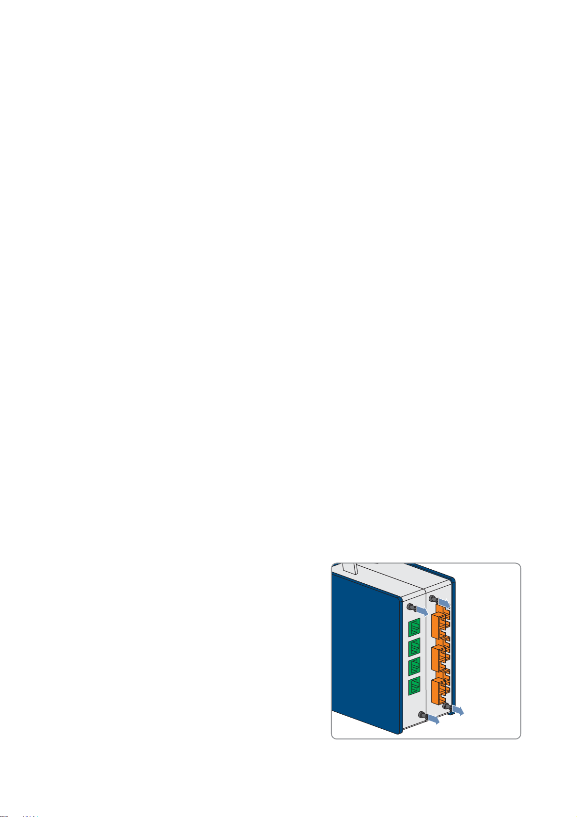
6.5 Connecting Network Cables and Optical Fibers
Cable requirements:
☐ Network cable: at least CAT5E
☐ Optical fiber with multi-mode switch: class OM2 50/125 μm
☐ Optical fiber with single-mode network switch: class OM2 9/125 μm
To connect the network cables and the optical fibers to the patch panel, carry out the following steps in the given
sequence. The exact procedure is described in the following sections.
Procedure:
1. Disassemble the modules of the patch panel.
2. Install the optical fibers.
3. Install the network cables.
4. Mount the modules of the patch panel.
Disassembling the Modules of the Patch Panel
1. Remove the patch cables.
2. Loosen two screws at the front of each module.
3. Pull out the modules from the front of the patch panel enclosure
24 PPC-BE-P7-en-13 Operating Manual
Page 25

SMA Solar Technology AG 6 Installation
&$87,21
/05*$&
Installing the Optical Fibers
Damage to eyes due to visible and invisible laser radiation
The Power Plant Controller contains laser components. The laser beam is emitted at the end of the optical fiber.
Looking directly into the laser beam can cause eye damage.
• Do not look into the laser beam.
• Do not look at the laser beam using optical instruments.
• Do not point the laser beam at persons.
Damage to optical fibers due to too tight bend radii
Excessive bending or kinking of optical fibers will damage the fibers.
• Observe the minimum permissible bend radii of the optical fibers.
Additionally required mounting material (not included in the scope of delivery):
☐ Optical fiber pigtails with subscriber connectors or
☐ Subscriber connectors
Requirement:
☐ The optical fibers must be inserted in the Power Plant Controller (see Section11.1, page49).
Procedure:
1. Loosen the cable gland of the module.
2. Insert the optical fibers through the cable gland into the module.
3. Strip sufficient insulation off the optical fibers.
4. Install the optical fibers:
• If optical fiber pigtails are used, splice the optical fibers with the optical fiber pigtails and fasten the splice points
in the splice holders.
• If subscriber connectors are used, install the subscriber connectors on the optical fibers.
• Push the plug down until it locks in the adapters.
5. Position the fiber in the fiber holder. Observe the bend radii of the optical fibers.
6. Tighten the cable gland.
Installing the Network Cables
Requirement:
☐ The network cables must be inserted in the Power Plant Controller (see Section11.1, page49).
Procedure:
1. Take the RJ45 Keystone pin connectors out of the accessory kit.
2. Connect the network cables to the RJ45 Keystone pin connectors (see Section11.2.3, page52).
3. Push the RJ45 Keystone pin connectors down until they lock in the cutouts of the module.
4. Secure the network cables to the metal bracket with the Velcro strip provided.
Operating Manual PPC-BE-P7-en-13 25
Page 26

6 Installation SMA Solar Technology AG
Mounting the Modules of the Patch Panel
1. Insert the module with the installed cables in the enclosure of the patch panel.
2. Attach the modules to the front side using two screws each.
3. Connect the patch cables. Observe the send and receive direction of the optical fibers.
26 PPC-BE-P7-en-13 Operating Manual
Page 27

SMA Solar Technology AG 7 Operation
/05*$&
7 Operation
7.1 Safety during Operation
Operation failure of the PV system due to incorrectly set parameters
If the parameter settings for grid management services are incorrect, the PV system may not be able to meet the
requirements of grid management services. This may lead to yield losses and disconnection of the inverters by the grid
operator.
• When setting the modes of grid management services, ensure that the control procedures agreed with the grid
operator are parameterized.
• If the PV system is operated with a Power Plant Controller, ensure that the procedure WCtlCom for active power
limitation and the procedure VArCtlCom for reactive power control are selected in the Sunny Central.
7.2 Adjusting Network Settings on the Computer
In order to access the Power Plant Controller user interface, the network settings of the computer must tally with those of
the Power Plant Controller. If the network address of the computer is not located in the same address range as the network
address of the Power Plant Controller, you will first need to adjust the network settings of the computer.
Procedure:
1. Write down the current IP address of the computer.
2. Adjust the IP address of the computer to the address range of the Power Plant Controller.
7.3 Installing the Droid Sans Font on the Computer
You can access the user interface via the display of the Power Plant Controller or with a computer via the system network.
If you wish to access the user interface via the system network, you will need to have the license-free font Droid Sans
installed on the computer to ensure error-free display.
Procedure:
• In Windows XP, check under Windows Start > Control Panel > Fonts whether the font Droid Sans is already
installed. If this font is installed, no further steps are necessary. If the font Droid Sans is not yet installed, download it
from the Internet and install.
or
•In Windows 7 check under Control Panel > Appearance and Personalization > Fonts whether the font Droid
Sans is already installed. If this font is installed, no further steps are necessary. If the font Droid Sans is not yet
installed, download it from the Internet and install.
7.4 Changing the Password
After initial login on the user interface of the Power Plant Controller, you should change the password of the
Power Plant Controller to protect your system. As long as the password is still rated insecure by the system, the request
Please change your password! will continue to be displayed in the bottom line of the user interface.
If you are logged in as user, you can change the user password. If you are logged in as installer, you can change the
user password and the installer password. Be sure to create a password that conforms to the guidelines for secure
passwords (see Section13.5, page59).
Operating Manual PPC-BE-P7-en-13 27
Page 28

7 Operation SMA Solar Technology AG
Procedure:
1. Log into the user interface (see Section11.3.1, page54).
2. Go to PPC > Settings > Access control.
3. To change the user password:
• Enter the new password in the field Set user password.
• Repeat the new password in the field Confirm password.
4. To change the installer password:
• Enter the new password in the field Set installer password.
• Repeat the new password in the field Confirm password.
5. Select [Save].
☑The [Next] button and the message You have changed the password appear.
6. Select [Next]. This completes the password changing procedure.
7.5 Changing Language and Time Settings
You can change the language of the user interface and the time settings. For the time setting, you can choose between
entering the date and time manually or having the time settings entered from an external source.
Procedure:
1. Log into the user interface (see Section11.3.1, page54).
2. Go to PPC > Settings > Device.
3. To change the language of the user interface, select the desired language in the field Language.
4. To set up time input from a time server, proceed as follows:
• In the drop-down list Time server activated, select Yes.
• Enter the IP address in the field IP address.
• To save the settings, click the [Ok] button in the field Save settings.
• To adjust the time zone, select the correct time difference to UTC in the drop-down list Time zone.
5. To set the time manually, make the appropriate settings in the fields Date and Time of day.
6. To complete the time setting, click the [Ok] button in the field Save date and time.
7.6 Adjusting the Device Settings
7.6.1 Adjusting IP Addresses of the Power Plant Controller
If the system network is changed after commissioning the Power Plant Controller, it may be necessary to adjust the IP
addresses of the Power Plant Controller.
For the assignment of system devices within the networks, be sure to comply with the recommended setup of the system
network (see Section13.1, page57).
Procedure:
1. Log into the user interface (see Section11.3.1, page54).
2. Go to PPC > Settings > System communication > PPC.
3. To adjust the IP address of the Power Plant Controller, configure the settings at the relevant inputs.
4. To save the Power Plant Controller network settings, click the button [Ok].
☑ After saving the network settings, you will be automatically logged off from the Power Plant Controller.
28 PPC-BE-P7-en-13 Operating Manual
Page 29

SMA Solar Technology AG 7 Operation
7.6.2 Adjusting the Configuration of the Sunny Centrals
After commissioning the Power Plant Controller, you can still change the IP address of individual Sunny Centrals, assign
a unique name to Sunny Centrals or disable the setpoint specified by the Power Plant Controller for individual
Sunny Centrals.
Figure13: User interface: Device table inverters (example)
Procedure:
1. Log into the user interface as an installer (see Section11.3.1, page54).
2. Go to PPC > Grid system services > Device table inverters.
3. Adjust the desired settings for the Sunny Centrals as follows:
– enter a unique name for the inverter in the field Device name
– deactivate the setpoint specified by the Power Plant Controller in the Active column (adjust setting to FALSE) or
activate (adjust setting to TRUE)
– change the IP address, port and UID of the inverter
– in the field Read profile, change the profile of the Modbus protocol with which the measured values are
transmitted by the Sunny Central.
Profile Explanation
0 The standard SMA Modbus protocol is used.
1 The Power Plant Controller Modbus profile is used. This option is applicable for future use.
Operating Manual PPC-BE-P7-en-13 29
Page 30

7 Operation SMA Solar Technology AG
– adjust the accuracy with which the output values are sent to the devices of the PV system in the field Write
profile:
Profile Explanation
0 The output values are transmitted with an accuracy of 1%.
1 The output values are transmitted with an accuracy of 0.01%.
– enter the control group in which the Sunny Central is connected to the respective MV transformer. Depending on
the MV transformer, one or two Sunny Centrals can be connected in each control group. Generally, the
Sunny Central devices or the control groups, respectively, can be numbered consecutively.
– Adjust the nominal power of the Sunny Central in [kW] in the field Pac Nom.
– Make the desired settings in the remaining columns:
Column Setting
MB Time Server Activation (TRUE) / deactivation (FALSE) of the specification of time through an external
Modbus time server
Q at Night Activation (TRUE) / deactivation (FALSE) of the "Q at Night" function in the inverters if this
function is available
Qac Nom Input of the nominal reactive power for the particular inverter
first Q limit The first threshold of the reactive power for the particular inverter. If this lower reactive power
limit is reached during operation, the inverter no longer receives higher output values initially.
The effectiveness of this threshold is, however, canceled if the inverter would be able
mathematically to supply reactive powers above the second threshold.
second Q limit The second threshold of the reactive power for the particular inverter.
If the first Q limit and the second Q limit were selected identically (default setting),
this function is deactivated.
7.6.3 Adjusting the Configuration of the Cluster Controllers and
Inverter
After commissioning the Power Plant Controller, you can still change the IP address of individual Cluster Controllers and
Inverter Managers, assign theses devices unique names or disable the setpoint specified by the Power Plant Controller
for individual devices.
Procedure:
1. Log into the user interface as an installer (see Section11.3.1, page54).
2. Go to PPC > Grid system services > Device table Modbus gateways.
3. Adjust the desired settings for each device:
– enter a unique name for the Cluster Controller or the Inverter Manager in the field Device name
Managers
– deactivate the setpoint specified by the Power Plant Controller in the Active column (adjust setting to FALSE) or
activate (adjust setting to TRUE)
– change the IP address, port and UID of the Cluster Controller
– enter a device type matching the respective device in the Model field:
Model Designation
1 Cluster Controller
2 Inverter Manager
– adjust the nominal power of the inverters assigned to the Cluster Controller in [kW] in the field Pac Nom
30 PPC-BE-P7-en-13 Operating Manual
Page 31

SMA Solar Technology AG 7 Operation
– Make the desired settings in the remaining columns:
Column Setting
MB Time Server Activation (TRUE) / deactivation (FALSE) of the specification of time through an external
Modbus time server
Q at Night Activation (TRUE) / deactivation (FALSE) of the "Q at Night: function in the inverters if this
function is available
Qac Nom Input of the nominal reactive power as a total of all inverters connected to the Cluster
Controller
first Q limit The first threshold of the reactive power for all inverters connected to the Cluster Controller.
If this lower reactive power limit is reached during operation, the inverters no longer receive
higher output values initially. The effectiveness of this threshold is however canceled if the
inverters would be able mathematically to supply reactive powers above the second
threshold.
second Q limit The second threshold of the reactive power for all inverters connected to the
Cluster Controller.
If the first Q limit and the second Q limit were selected identically (default setting),
this function is deactivated.
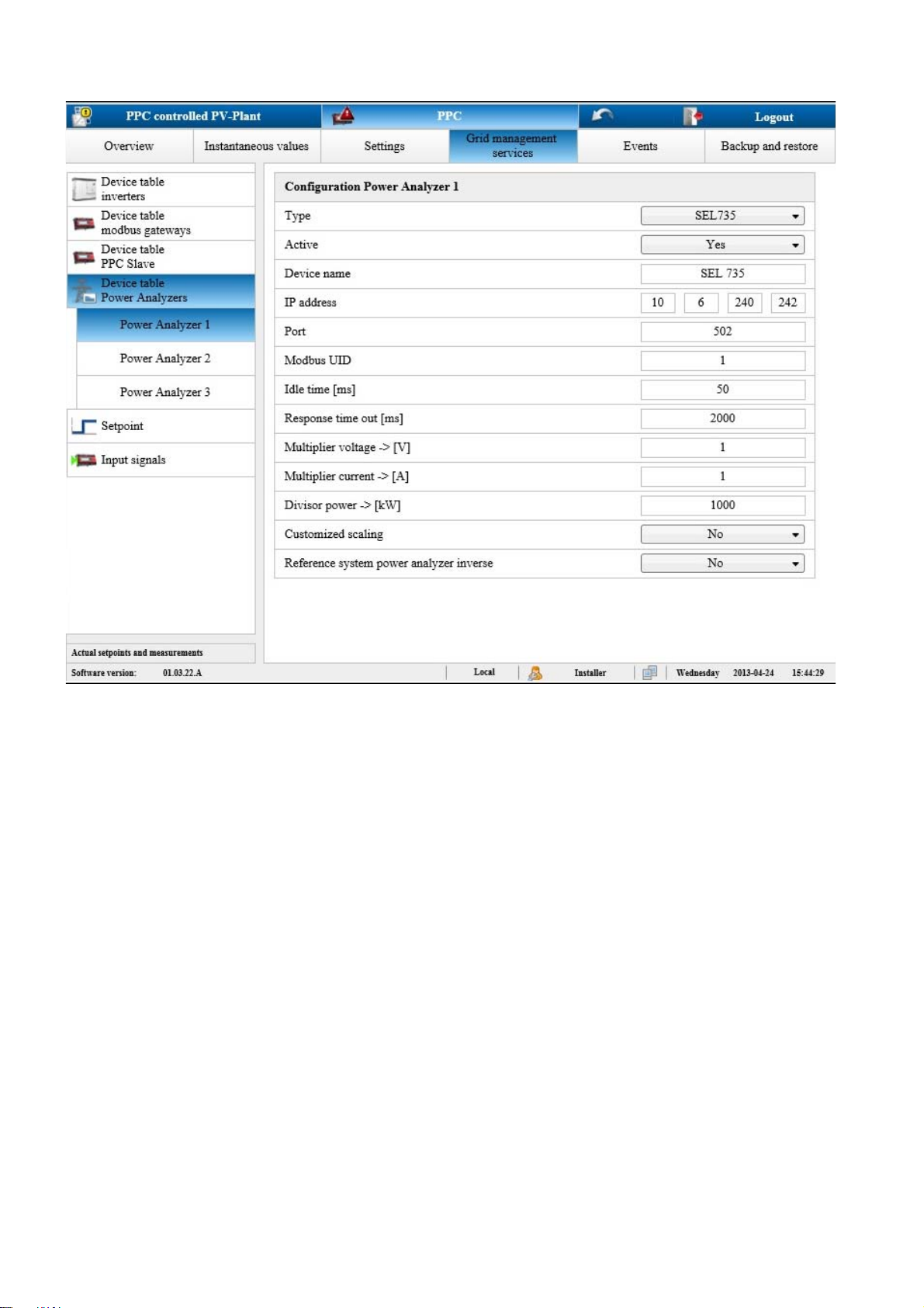
7.6.4 Adjusting the Configuration of the Network Analyzers
At the point of interconnection, the current values for active power, reactive power, voltage and frequency are measured.
The measured values are captured in up to three network analyzers. For each variable, a network analyzer can be
selected as the source for the default value. A second network analyzer independent of the first network analyzer can be
selected as the source for the redundant second measured value. If one of the default values fails, the redundant second
measured value will be used in its place.
The measured values are either queried by the Power Plant Controller via Modbus using a network analyzer or submitted
to the Power Plant Controller as analog input signals.
In order to ensure the correct processing of the measured values, the network analyzer used must be configured.
After commissioning the Power Plant Controller, you can still change the IP address of the network analyzer, adjust its
device type and assign it a unique name.
If a network analyzer is to be serviced or replaced, measurements by this network analyzer should be deactivated in
advance.
Operating Manual PPC-BE-P7-en-13 31
Page 32
7 Operation SMA Solar Technology AG
Figure14: User interface: Device table - network analyzers (example)
Procedure:
1. Log into the user interface as an installer (see Section11.3.1, page54).
2. Go to PPC > Grid system services > Device table Power Analyzers > Power Analyzer 1.
3. If you need to disable network analyzer 1, adjust the setting in the Active column to FALSE.
4. If you need to enable network analyzer 1, adjust the setting in the Active column to TRUE.
5. To change the device type of the network analyzer, click the corresponding button next to the field Type and select
the appropriate device from the device list.
6. To assign a name to a device, enter the desired device name in the field Device name.
7. To change the IP address of a network analyzer, change the IP address of the respective network analyzer in the
corresponding fields.
8. To scale the instantaneous values of voltage, electric current or power, adjust the settings in the associated fields.
9. To scale the input signals on the page PPC > Settings > Modbus server > Standard, in the drop-down list
Customized scaling, select the entry Yes. If No is selected, individual scaling of the measured values P, Q, U and
f is not possible.
10. To adjust the settings for the other network analyzers, go to PPC > Grid system services > Device table Power
Analyzers > Power Analyzer 2 or PPC > Grid system services > Device table Power Analyzers > Power
Analyzer 3.
32 PPC-BE-P7-en-13 Operating Manual
Page 33

SMA Solar Technology AG 7 Operation
7.6.5 Adjusting the Configuration of the Power Plant Controller Slaves
Using Power Plant Controllers, you can monitor a PV power plant with up to 1,000 central inverters. The master/slave
concept of the Power Plant Controllers enables all 1,000 inverters to be controlled uniformly and simultaneously.
The Power Plant Controller master transmits the output values for the active and reactive power control to the
Power Plant Controller slaves and to all inverters connected to the master. A Power Plant Controller master can control
up to ten Power Plant Controller slaves.
In the Power Plant Controller master, the IP addresses of the Power Plant Controller slaves and the mode of the slave
operation must be set. If necessary, the Power Plant Controller slaves can be divided into different control groups. It can
also be set whether the Power Plant Controller master must pass the disconnect command to the slave or not. The settings
for the fast stop command can only be made using the user level "service technician".
Procedure:
1. Log into the user interface of the master as an installer (see Section11.3.1, page54).
2. Go to PPC > Grid system services > Device table PPC slave.
3. Enter the number of slaves for this Power Plant Controller master in the Number PPC slave field.
4. Enter the name of the slave in the Device name field.
5. Enter the IP address of the slave in the fields IP1 to IP4.
6. Adjust the setting for the mode of the slave operation in the Slave mode field:
Mode of slave
operation
1 The active power setpoints are processed by the controller of the master and transmitted as
2 The reactive power setpoints are processed by the controller of the master and transmitted as
3 The active and reactive power setpoints are processed by the controller of the master and
Description
output values to the slave. The slave does not control but transmits the output values to the
inverters.
or
Cascade control: The active power output values of the master are processed by the slave
controller as setpoints and sent to the inverters. For this mode of slave operation, the slave
must receive the actual values from an additional network analyzer. This network analyzer
must record the values of the part of the PV power plant that is to be controlled. For cascade
control, therefore, an additional network analyzer is required for each slave.
The reactive power setpoints are processed by the slave's own controller.
output values to the slave. The slave does not control but transmits the output values to the
inverters.
The active power setpoints are processed by the slave's own controller.
transmitted as output values to the slave. The slave does not control but transmits the output
values to the inverters.
7. If necessary, enter the number of the group that the slave belongs to in the Control group field.
7.7 Adjusting the Settings of the Modbus Server
The communication between the Power Plant Controller and the grid operator or a higher-level SCADA system takes
place via Modbus protocol. You can disable communication with the grid operator via Modbus protocol and change
the IP address of the Modbus server. You can configure whether setpoint changes are only to be accepted if the change
counter register is set simultaneously in the Modbus protocol.
If the Modbus Client is inactive, the connection will automatically be cut off after 60 seconds, even if the setting Setpoint
monitoring is activated. The time can be adjusted from 1 s to 60 s in the field Setpoint monitoring time.
Operating Manual PPC-BE-P7-en-13 33
Page 34

7 Operation SMA Solar Technology AG
Procedure:
1. Log into the user interface as an installer (see Section11.3.1, page54).
2. Go to PPC > Settings > Modbus server.
3. To adjust the profile of the Modbus server, select the desired entry in the drop-down list Modbus server profile.
4. To enable or to disable the Modbus server, select the option Yes or No in the drop-down list Active.
5. In the drop-down list Release IP address range, select the desired option.
6. To enable automatic monitoring of the connection to the Modbus Client, perform the following steps:
• In the drop-down list Setpoint supervision, select the entry Yes.
•In the field Monitoring time setpoint supervision, enter the desired time.
☑ Once the waiting time has expired, the connection is interrupted by the Modbus server.
7. In the drop-down list Enable change counter, select Yes if required. If it is set to No, each change in the Modbus
protocol will be accepted as a setpoint change.
8. To enable scaling of the input signals on the page PPC > Grid system services > Input signals > Measurement
values, select Yes in the drop-down list Customized scaling.
7.8 Transmitting Output Values to Devices of the PV System
If anything in the system is changed after commissioning of the Power Plant Controller, it may be necessary to adjust the
transmission of the output values for the setpoint. It is possible to disable the transmission of output values or adjust the
mode of transmission of output values.
Procedure:
1. Log into the user interface (see Section11.3.1, page54).
2. To adjust the transmission of control values to the Sunny Central devices, select PPC > Settings > System
communication > Inverter.
3. Make the necessary changes in the appropriate fields as follows:
– enable or disable the transmission of output values in the drop-down list Active
– Enter the waiting time between two output value transmissions in the field Idle time [ms]. The recommended time
is 5 ms.
4. To adjust the transmission of control values to the Cluster Controllers, select PPC > Settings > System
communication > Cluster Controller.
5. Make the necessary changes in the appropriate fields as follows:
– Enable or disable the transmission of output values in the drop-down list Active
– Enter the waiting time between two output value transmissions in the field Idle time [ms]. The recommended time
is 1,000 ms.
7.9 Selecting the Signal Source and Adjusting the Scaling of Measured Values
The measured values of the PV system that are used to calculate the output values can be transmitted via various channels
to the Power Plant Controller. If the signal transmission changes after commissioning the Power Plant Controller, it can be
adjusted. The settings for the individual measured values of active power, reactive power, voltage, and frequency can
be made separately.
If an error occurs during transmission of the measured values via Modbus protocol, the last calculated output values can
be used (see Section13.4 "Output Value Specification Under Fault Conditions", page59), or you can use substitution
values (see Section7.10 "Local Specification of Setpoints", page37).
34 PPC-BE-P7-en-13 Operating Manual
Page 35

SMA Solar Technology AG 7 Operation
Measured values submitted to the Power Plant Controller as analog signals will be converted to digital values in the
Power Plant Controller. The measured values in technical units must be calculated from the digital signals. The signals
submitted by the transducer to the Power Plant Controller must be scaled (see Section13.3, page57). Scaling of the
measured data is only possible if under PPC > Settings > Modbus server or under PPC > Grid system services >
Device table Power Analyzers > Power Analyzer 1 the entry Yes has been selected in the drop-down list
Customized scaling, or if analog signals are used.
Operating Manual PPC-BE-P7-en-13 35
Page 36

7 Operation SMA Solar Technology AG
Procedure:
1. Log into the user interface (see Section11.3.1, page54).
2. Go to PPC > Grid system services > Input signals > Measurement values.
3. To assign the record from which the active power setpoint is to be calculated, select the button [Active power]
under Measured values 1 (default) or Measured values 2 (redundant) in the right-hand menu bar.
4. If an error has occurred and the Power Plant Controller needs to supply substitution values, select the entry Yes in
the drop-down list Substitution value and enter the required substitution value.
5. To switch the device or the input supplying the measured data, select the appropriate entry in the drop-down list
Signal source.
– Modbus server: The measured values are transmitted via Modbus protocol from the grid operator to the
Power Plant Controller.
– Modbus device: The measured values are transmitted via Modbus protocol from the network analyzer to the
Power Plant Controller.
– Onboard: The cables supplying the analog measured values are connected directly to the analog inputs of the
Power Plant Controller.
– Bus coupler: The cables supplying the analog measured values are connected to a bus terminal of the
Power Plant Controller.
6. If you have selected the setting Modbus device in the drop-down list Signal source, you will now need to define
the network analyzer at which the signal is present.
7. If you have selected the setting Onboard or Bus coupler in the drop-down list Signal source, you will now need
to define the input at which the signal is present. To do this, select the corresponding entry in the drop-down list
Hardware channel.
8. If the measured data are not supplied by a network analyzer or the network analyzer does not have an averaging
function, averaging of the data can be configured here. To do this, enter the desired number of values in the field
Averaging x values. Entries are possible between 1 (no averaging) and 10 (averaging from 10 measured
values).
9. If the measured data are supplied as analog signals, adjust the scaling of the measured values:
– in the field yMin., enter the lowest value in the range of valid measured values
– in the field yMax., enter the highest value in the range of valid measured values
– in the field x0, enter the lowest signal value supplied by the transducer
– in the field x1
– in the field y0, enter the lowest value in the measurement range
– in the field y1, enter the highest value in the measurement range
☑ When measured values are received without errors, No is displayed in the field Error.
✖ Yes is displayed in the Error field?
No measured values are being received by the Power Plant Controller or the values received are outside the
permitted range. An error is displayed and the substitution value is used.
10. To configure the settings for further measured values, repeat the settings from Step 3 for each setpoint.
11. To make settings for the measured values of the sensors, go to PPC > Grid system services > Input signals >
Measurements common.
12. Repeat settings from Step 3 for each sensor.
, enter the highest signal value supplied by the transducer
36 PPC-BE-P7-en-13 Operating Manual
Page 37

SMA Solar Technology AG 7 Operation
7.10 Local Specification of Setpoints
Control of the system by the Power Plant Controller is normally executed remotely via Modbus commands.
In addition, it is possible for the grid operator to specify fixed setpoints so that remote control of the system is not
necessary. In this case, the system control must be adjusted to Local.
If errors occur during transmission of grid management specifications via Modbus protocol, for diagnostic purposes the
system can be controlled directly from the user interface. To enable settings to be made via the user interface, the system
control needs to be adjusted to Local. After completion of the diagnostic work, reset system control to Remote.
Procedure:
1. Log into the user interface as an installer (see Section11.3.1, page54).
2. Go to PPC > Grid system services > Setpoint specification.
3. In the drop-down list System control, select the entry Local.
4. Enter the required values in the fields Active power, Reactive power, Voltage, Power factor and TanPhi.
7.11 Saving and Restoring Settings of the Power Plant Controller
Backing Up Settings
All settings of the Power Plant Controller can be backed up automatically and manually.
Settings backup Description
Automatic All Power Plant Controller settings are saved daily at midnight to the SD memory card in the
Power Plant Controller. This data is always saved alternately in the files AutoSave 1 and
AutoSave 2. This means that, in the event of an error, the records from two different days can be
retrieved. You can recognize which of the two files is the more recent by the date on the user
interface.
Manual It is possible to save all settings to a USB memory stick in one folder
PPC_Backup_xxxxxxxx(serial number). The folder name includes the serial number of the
Power Plant Controller. The Power Plant Controller automatically creates this folder. During
backup, the automatically saved files AutoSave 1 and AutoSave 2 are also transferred to the
USB memory stick.
In addition, all settings, or the settings of all inverters, Cluster Controllers, controllers and IP
addresses, can be saved separately in an internal file of the Power Plant Controller.
Procedure:
1. Log into the user interface (see Section11.3.1, page54).
2. Go to PPC > Backup and restore.
3. To export the settings to a USB memory stick, proceed as follows:
• Select the required USB port in the field Port.
• Select the button [Backup] in the field Ini files.
4. To save separate settings in an internal file on the Power Plant Controller, click the button [Export] of the respective
group.
5. To save all settings in an internal file on the Power Plant Controller, click the button [Export] of the group All.
Operating Manual PPC-BE-P7-en-13 37
Page 38

7 Operation SMA Solar Technology AG
Restoring Settings
All settings can be imported from three different sources on the Power Plant Controller.
Source of saved
settings
USB memory stick If the settings have been saved beforehand to a USB memory stick in a folder
Files AutoSave 1
and AutoSave 2
Internal file of the
Power Plant
Controller
Procedure:
1. Log into the user interface (see Section11.3.1, page54).
2. Go to PPC > Backup and restore.
3. To import the settings from a USB memory stick, proceed as follows:
• Select the required USB port in the field Port.
• Select the button [Restore] in the field Ini files.
• In the open window, select the desired entry from the drop-down list Data source for import:
Description
PPC_Backup_Serial number, these settings can be restored. To do this, all files must be
copied to a folder PPC_Restore_Config. When restoring the file, you can choose whether
the settings are to be imported from the files AutoSave 1 and AutoSave 2 or from the
manually saved export files.
All settings, or the settings of all inverters, Cluster Controllers, controllers, and IP addresses can
be restored separately from the automatically saved files.
If the settings of the Power Plant Controller have been changed but no back up has taken place,
it is possible to restore the settings status stored in the Power Plant Controller. In this case, any
changes made previously are overruled.
Entry Explanation
Export files Settings are imported from the manually saved files.
AutoSave 1 Settings are imported from the file AutoSave 1.
AutoSave 2 Settings are imported from the file AutoSave 2.
• Select the button [Yes].
4. To import settings from the automatically saved files AutoSave 1 and AutoSave 2, proceed as follows:
• Select the desired entry in the drop-down list Data source for import.
• Click the [Import] button next to the desired settings.
5. To import settings from the internal file of the Power Plant Controller, proceed as follows:
• In the drop-down list Data source for import, select the entry Export files.
• Click the [Import] button next to the desired settings.
38 PPC-BE-P7-en-13 Operating Manual
Page 39

SMA Solar Technology AG 7 Operation
7.12 Calling Up the System Overview
7.12.1 Calling Up the Overview of the Entire System
In the overview "My system" you will find an overview of the current data of the entire PV system and the status of the
measured values.
To facilitate identification of your system, you can enter the name of your system on this page. This name will then appear
instead of "My system" in the first-level navigation line.
Procedure:
1. Log into the user interface (see Section11.3.1, page54).
☑The overview "My system" now opens.
2. If required, enter the name of the system in the field System name.
3. If required, adjust the power of the PV system in the field System power (in installer mode).
7.12.2 Retrieving the Status and Current Data of All Devices in the System
1. Log into the user interface (see Section11.3.1, page54).
2. To call up an overview of the number of devices in the PV system and the status of these devices, select PPC >
Overview.
3. To call up the data of the connected sensors, go to PPC > Measurement values > Measurements common.
4. To call up the status and the current data of the connected inverters, go to PPC > Spot values > System
communication > Inverter.
5. To call up the status and the current data of the connected Cluster Controllers, go to PPC > Spot values > System
communication > Cluster Controller.
6. To call up the current data of the network analyzers, go to PPC > Spot values > System communication > Power
Analyzer.
Operating Manual PPC-BE-P7-en-13 39
Page 40

8 Troubleshooting SMA Solar Technology AG
8 Troubleshooting
8.1 Calling up Information on Software Version and Service-Relevant Information
You can find service-relevant information (required if a fault has occurred) in the dialog Type label.
Procedure:
1. Log into the user interface as an installer (see Section11.3.1, page54).
2. Select PPC > Settings > Nameplate.
8.2 Calling-Up and Acknowledging Error, Warning and Event Messages
Errors, warnings or events that occur in the PV system and are saved in the Power Plant Controller are displayed via the
user interface of the Power Plant Controller. When the cause of the message has been eliminated, the message can be
acknowledged on the user interface.
Procedure:
1. Log into the user interface (see Section11.3.1, page54).
2. To display errors, select PPC > Events > Messages > Error.
3. To display warnings, select PPC > Events > Messages > Warning.
4. To acknowledge individual, highlighted messages, go to the relevant page and click the button [ACK selected].
5. To acknowledge all messages, go to the relevant page and click the button [ACK all visible].
8.3 Errors and Warnings
Error text Explanation
Inverter: Warning A warning is displayed on the Sunny Central (see Sunny Central user manual)
Inverter: Error network The Sunny Central cannot be reached via the network.
CLCON: Error Network The Cluster Controller cannot be reached via the network.
Measurement 1: Voltage error The measured value of the voltage from record 1 is outside the valid
measurement range.
Measurement 1: Frequency error The measured value of the frequency from record 1 is outside the valid
measurement range.
Measurement 1: Active power error The measured value of the active power from record 1 is outside the valid
measurement range.
Measurement 1: Reactive power error The measured value of the reactive power from record 1 is outside the valid
measurement range.
Measurement 2: Voltage error The measured value of the voltage from record 2 is outside the valid
measurement range.
Measurement 2: Frequency error The measured value of the frequency from record 2 is outside the valid
measurement range.
Measurement 2: Active power error The measured value of the active power from record 2 is outside the valid
measurement range.
Measurement 2: Reactive power error The measured value of the reactive power from record 2 is outside the valid
measurement range.
40 PPC-BE-P7-en-13 Operating Manual
Page 41

SMA Solar Technology AG 8 Troubleshooting
Error text Explanation
Measured voltage error, controller in
manual mode
Measured frequency error, controller in
manual mode
Measured active power error,
controller in manual mode
Measured reactive power error,
controller in manual mode
Warning control deviation high Information indicating that the controlled value deviates significantly from the
Upper control limit reached Information indicating that the output value has reached the upper threshold.
The measured values of the voltage from both records are outside the valid
measurement range. The controller switches to manual operation and
transmits the last value calculated prior to the error, or a substitution value, as
output value to the Sunny Centrals and the Cluster Controllers.
The measured values of the frequency from both records are outside the valid
measurement range. The controller switches to manual operation and
transmits the last value calculated prior to the error, or a substitution value, as
output value to the Sunny Centrals and the Cluster Controllers.
The measured values of the active power from both records are outside the
valid measurement range. The controller switches to manual operation and
transmits the last value calculated prior to the error, or a substitution value, as
output value to the Sunny Centrals and the Cluster Controllers.
The measured values of the reactive power from both records are outside the
valid measurement range. The controller switches to manual operation and
transmits the last value calculated prior to the error, or a substitution value, as
output value to the Sunny Centrals and the Cluster Controllers.
setpoint (for example, at current irradiation levels the configured values for
active power cannot be achieved).
Lower control limit reached Information indicating that the output value has reached the lower threshold.
Warning limitation apparent power
active
Warning P(f) control active Information indicating that the power frequency is above the configured
Information indicating that the apparent power is limited by the
Power Plant Controller.
threshold and that active power feed-in is being reduced to provide grid relief.
8.4 Corrective Measures in the Event of Disturbance
Problem Cause and corrective measures
The Power Plant Controller
does not start. The LEDs and
the display are off.
The login page does not
open.
The Power Plant Controller is not connected to the voltage supply.
Corrective measures:
• Ensure that the supply voltage is connected correctly (see Section6.2, page22).
The voltage supply is reverse-connected or the top-hat rail power supply unit is defective.
Corrective measures:
• Ensure that the supply voltage is connected correctly (see Section6.2, page22).
• If the voltage supply is connected correctly, replace the top-hat rail power supply
unit.
The Power Plant Controller could not start correctly. A system error has occurred.
Corrective measures:
• Disconnect the Power Plant Controller from the voltage supply and then reconnect.
Note that this can lead to loss of system data.
• If the problem persists, contact the SMA Service Line.
Operating Manual PPC-BE-P7-en-13 41
Page 42

8 Troubleshooting SMA Solar Technology AG
Problem Cause and corrective measures
The login page does not
open.
The Power Plant Controller is not connected to the supply voltage.
Corrective measures:
• Ensure that the supply voltage is connected correctly (see Section6.2, page22).
The voltage supply is reverse-connected or the top-hat rail power supply unit is defective.
Corrective measures:
• Ensure that the supply voltage is connected correctly (see Section6.2, page22).
• If the supply voltage is connected correctly, replace the top-hat rail power supply
unit.
A firewall is blocking the connection.
Corrective measures:
• Adjust the firewall settings in order to allow the required connection.
• Ensure that port 8080 is activated.
There is a problem in the local area network (LAN).
Corrective measures:
• Ensure that the network cables are correctly connected to the
Power Plant Controller (see Section6.5, page24).
• Check whether the network components, network cables or connectors are
defective or damaged. Replace defective or damaged network components,
network cables or connectors.
Login to the user interface
has failed.
• Check whether the network settings of the individual network components are
correct. Adapt the network settings if required.
• Restart the Power Plant Controller. To do this, disconnect the Power Plant Controller
from the voltage supply and then reconnect. Note that this can lead to loss of
system data.
• If the problem persists, contact the network administrator.
If the Power Plant Controller is accessed via the Internet, it is possible that there is
currently no Internet connection, that port forwarding to the Power Plant Controller from
the router has failed or been set up incorrectly, or that an incorrect gateway has been
configured.
Corrective measures:
• In the event of interrupted Internet connection, restore the Internet connection.
• If port forwarding has not been set up, set up port forwarding to the
Power Plant Controller at the router.
• If port forwarding has already been set up at the router, ensure that it has been set
up correctly.
• Check the gateway settings in the Power Plant Controller and adjust them if
necessary.
The password entered is incorrect. Access to the Power Plant Controller is suspended for
a maximum of five minutes.
Corrective measures:
• Wait five minutes, then log in with the correct system password.
42 PPC-BE-P7-en-13 Operating Manual
Page 43

SMA Solar Technology AG 8 Troubleshooting
Problem Cause and corrective measures
The user interface is not
displayed properly.
At least one device has the
status Warning or Error.
Communication with at least
one device is disturbed.
The Droid Sans font is not installed.
Corrective measures:
• Install the Droid Sans font.
There may be a disturbance in one of the connected devices.
Corrective measures:
• Check the event log (see Section8.3, page40).
• Refer to the device documentation.
There may be a disturbance in the device.
Corrective measures:
• Check the event log (see Section8.3, page40).
• Refer to the device documentation.
The connection between the Power Plant Controller and the connected devices may
have failed.
Corrective measures:
• Ensure that the network cables are connected correctly (see Section6.5, page24).
• Check whether the network components, network cables or connectors are
defective or damaged. Replace defective or damaged network components,
network cables or connectors.
• Check whether the network settings of the individual network components are
correct. Adapt the network settings if required.
• If the problem persists, contact the network administrator.
Communication with all
devices is disturbed.
There is a problem in the local area network (LAN).
Corrective measures:
• Ensure that the network cables are connected correctly (see Section6.5, page24).
• Check whether the network components, network cables or connectors are
defective or damaged. Replace defective or damaged network components,
network cables or connectors.
• Check whether the network settings of the individual network components are
correct. Adapt the network settings if required.
• Restart the Power Plant Controller. To do this, disconnect the Power Plant Controller
from the voltage supply and then reconnect.
• If the problem persists, contact the network administrator.
Operating Manual PPC-BE-P7-en-13 43
Page 44

8 Troubleshooting SMA Solar Technology AG
Problem Cause and corrective measures
The correct total number of
connected inverters is not
shown on the user interface
or the display.
The parameters or settings of
an individual device cannot
be edited.
The Power Plant Controller
cannot be accessed by the
Modbus client.
The configuration of the connected devices has been entered incorrectly in the
Power Plant Controller.
Corrective measures:
• Ensure that the inverters are in operation (see inverter installation manual).
• Ensure that the network cables interconnecting the inverters are connected correctly
(see Section6.5, page24).
• Ensure that the network terminals of the Sunny Centrals are connected correctly to
the Power Plant Controller.
• Ensure that no network components, network cables or connectors are defective.
• Ensure that the network addresses of the connected devices are entered correctly.
You do not have the necessary authorization to edit the parameters.
Corrective measures:
• Change the user group (see Section11.3.1 "Logging Into the User Interface",
page54).
The required Modbus server is not enabled.
Corrective measures:
• Ensure that the required Modbus server is enabled (see Section7.7, page33).
The Modbus profile contains
measured values that are not
supported by the
Power Plant Controller.
The Power Plant Controller is
not responding within the
response time specified by
the Modbus client.
An incorrect IP address for the Power Plant Controller has been set in the Modbus client.
Corrective measures:
• Read off the IP address of the Power Plant Controller (see Section7.6.1, page28).
• Ensure that the correct IP address for the Power Plant Controller is set in the Modbus
client (see the manufacturer manual).
The Modbus configuration may be incorrect.
Corrective measures:
• Check the Modbus configuration using the assignment tables and adjust if required
(see Section7.7, page33).
The Modbus configuration may be incorrect.
Corrective measures:
• Check the Modbus configuration using the assignment tables and adjust if required
(see Section7.7, page33).
The network configuration may be incorrect.
Corrective measures:
• Ensure that the network cables are connected correctly (see Section6.5, page24).
• Check whether the network components, network cables or connectors are
defective or damaged. Replace defective or damaged network components,
network cables or connectors.
• Check whether the network settings of the individual network components are
correct. Adapt the network settings if required.
• If the problem persists, contact the network administrator.
44 PPC-BE-P7-en-13 Operating Manual
Page 45

SMA Solar Technology AG 8 Troubleshooting
Problem Cause and corrective measures
A value specified in the
Modbus profile is not being
transmitted by the
Power Plant Controller to the
devices in the system.
The Modbus configuration may be incorrect.
Corrective measures:
• Check the Modbus configuration using the assignment tables and adjust if required
(see Section7.7, page33).
The setpoint specification may have been set to local.
Corrective measures:
• Ensure that the setpoint is set to Remote.
Operating Manual PPC-BE-P7-en-13 45
Page 46

9 Maintenance SMA Solar Technology AG
9 Maintenance
9.1 Maintenance and Replacement Intervals
• The Power Plant Controller must be serviced every 24 months.
• Replace the SD memory card of the Power Plant Controller every ten years (see Section9.5, page47).
9.2 Checking the Mounting Location
• Ensure that the mounting location is easily accessible without the need of auxiliary equipment.
• Make sure that the Power Plant Controller is securely mounted.
9.3 Switching the Power Plant Controller On and Off
Switching the Power Plant Controller On
Requirement:
☐ Supply voltage must be present.
Procedure:
1. Open the door of the Power Plant Controller.
2. Switch on the circuit breakers.
3. Close and lock the door of the Power Plant Controller.
Switching the Power Plant Controller Off
1. Open the door of the Power Plant Controller.
2. Switch off the circuit breakers.
3. Close and lock the door of the Power Plant Controller.
4. Disconnect the supply voltage externally, if necessary.
46 PPC-BE-P7-en-13 Operating Manual
Page 47

SMA Solar Technology AG 9 Maintenance
9.4 Checking the Enclosure and Enclosure Interior
Only perform maintenance work on the Power Plant Controller when the environment is dry and free of dust.
Procedure:
• Check whether the enclosure of the Power Plant Controller is damaged or soiled.
If the enclosure is severely damaged, contact the SMA Service Line.
• Ensure that the enclosure is clean.
• Ensure that the door lock is intact and clean.
• Check whether the surrounding seals on the door frames are intact.
If the seals are damaged, replace them.
• Ensure that all cable glands are tightly sealed.
9.5 Replacing the SD Memory Card of the Power Plant Controller
The SD memory card of the Power Plant Controller must be replaced every ten years. Fault-free operation of the
Power Plant Controller can only be guaranteed if an SD memory card approved by SMA Solar Technology AG is
inserted.
Requirements:
☐ The new SD memory card must be an industrial SD memory card.*
☐ The Power Plant Controller must be switched off (see Section9.3, page46).
Procedure:
1. Remove the cover. Press on the cover from the left and pull the
cover outwards.
2. Remove the SD memory card. Briefly press the SD memory card into the slot.
3. Insert the new SD memory card.
4. Position the cover. Insert the bracket in the right-hand opening and
press the cover inwards. Make sure that the buttons are not
clamped.
☑ The enclosure snaps into place.
* Contact the SMA Service Line to insert an SD memory card suitable for your Power Plant Controller.
Operating Manual PPC-BE-P7-en-13 47
Page 48

10 Decommissioning SMA Solar Technology AG
10 Decommissioning
10.1 Disassembling the Power Plant Controller
Requirement:
☐ The supply voltage must be externally disconnected.
Procedure:
1. Open the door of the Power Plant Controller.
2. Remove all network cables and optical fibers.
3. Disconnect all signal cables.
4. Remove the voltage supply cable.
5. Release the cable glands.
6. Pull all cables out of the cable glands and the cable feed-through plate.
7. Disassemble the Power Plant Controller.
10.2 Disposing of the Power Plant Controller
• Dispose of the Power Plant Controller in accordance with the locally applicable disposal regulations for electronic
waste.
48 PPC-BE-P7-en-13 Operating Manual
Page 49
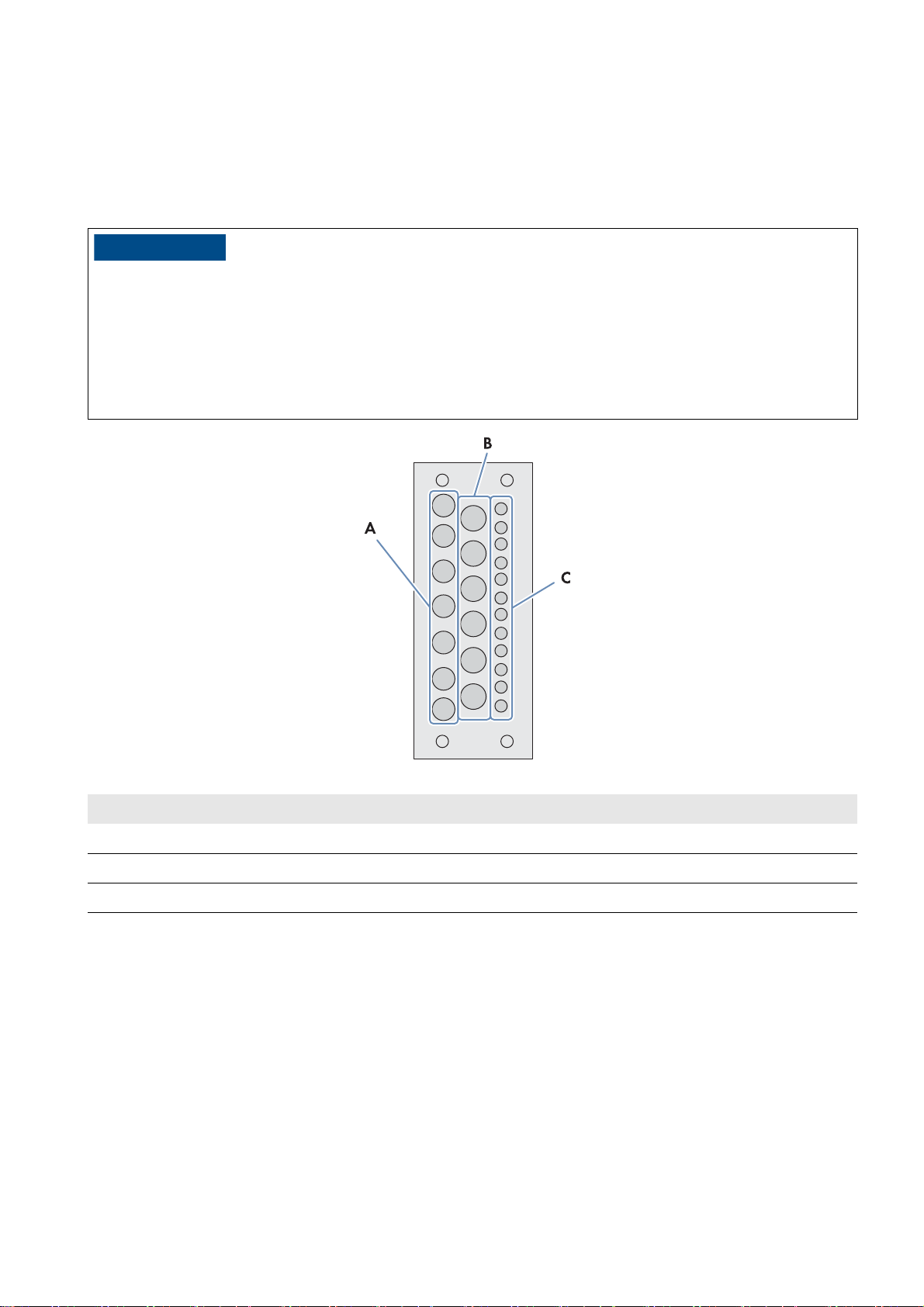
SMA Solar Technology AG 11 Periodic Actions
/05*$&
11 Periodic Actions
11.1 Cable Entry
11.1.1 Inserting the Cable into the Cable Feed-Through Plate
Damage to the Power Plant Controller due to moisture penetration
Excessively large or redundant holes in the membranes of the cable feed-through plate can cause moisture to penetrate
the Power Plant Controller.
• Select membranes that match the cable diameter.
• Avoid piercing needlessly large holes in the membranes of the cable feed-through plate.
• Only pierce as many holes in the membranes of the cable feed-through plate as you need for the cables.
Figure15: Overview of the membranes for inserting the cable
Position Explanation
A Membranes for cable cross-section from 4.8 mm to 9.7 mm
B Membranes for cable cross-section from 4.8 mm to 12.0 mm
C Membranes for cable cross-section from 3.2 mm to 6.5 mm
Procedure:
1. Pierce a hole in the respective membrane.
2. Insert the cables in the holes.
3. Cut the cables to length.
4. Attach the cables to an external cable support rail.
Operating Manual PPC-BE-P7-en-13 49
Page 50
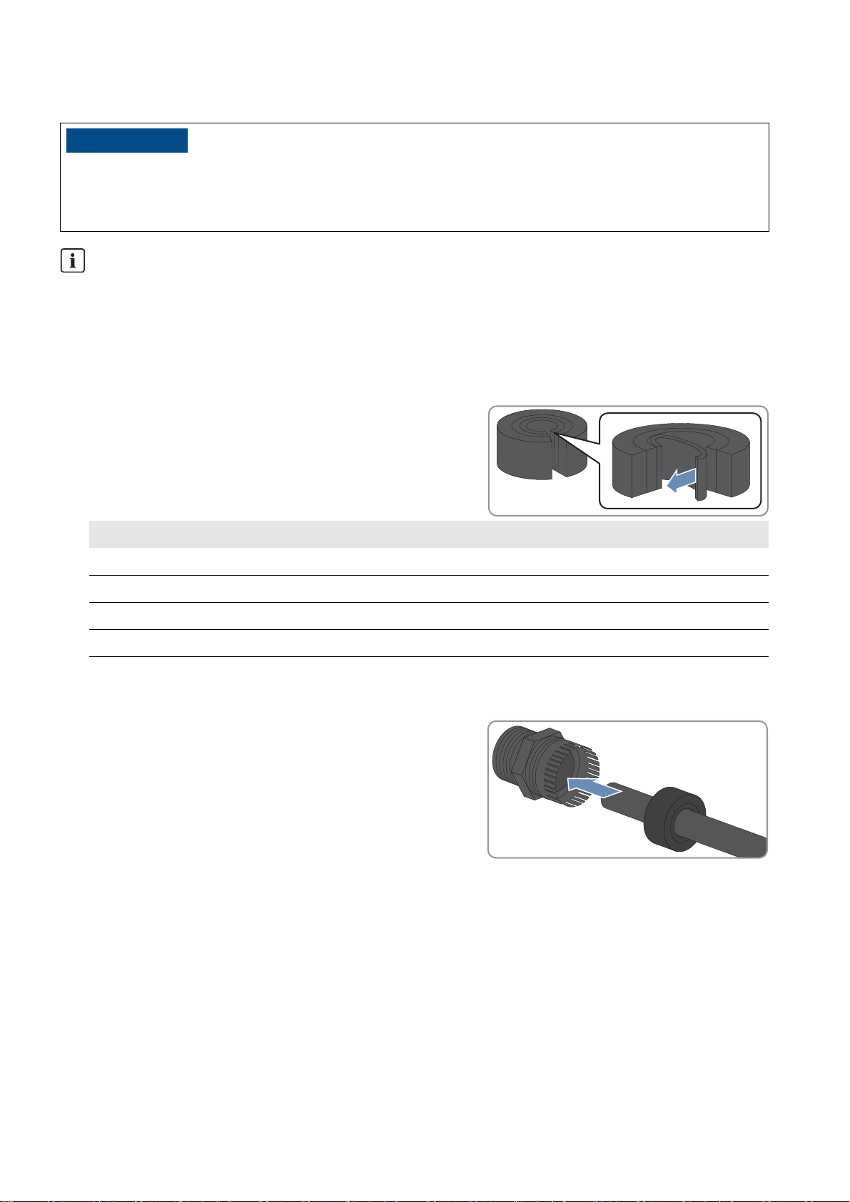
11 Periodic Actions SMA Solar Technology AG
/05*$&
11.1.2 Inserting the Cable in the Cable Gland
Damage to the Power Plant Controller due to moisture penetration
Moisture can penetrate the Power Plant Controller due to unsealed cable glands.
• Only remove the number of sealing rings from the rubber seal in the cable gland to match the cable cross-section.
Unused cable glands
• Do not take the filler plugs out of the unused cable glands. This keeps the Power Plant Controller sealed.
Procedure:
1. Remove the filler plug from the cable gland.
2. Remove the rubber seal from the cable gland.
3. Adjust the rubber seal to the diameter of the cable to be inserted:
• Remove the appropriate number of sealing rings from the
rubber seal.
Cable diameter Number of sealing rings to be removed
4.5 mm to 5.0 mm 0
4.5 mm to 7.5 mm 1
7.0 mm to 10.0 mm 2
9.5 mm to 13.0 mm 3
4. Lead the cable through the swivel nut of the cable gland. Ensure that the thread of the swivel nut is facing upwards.
5. Lead the cable above the swivel nut sideways through the rubber seal.
6. Insert the rubber seal with the cable into the cable gland.
7. Cut the cable to length.
8. Tighten the cable gland.
50 PPC-BE-P7-en-13 Operating Manual
Page 51
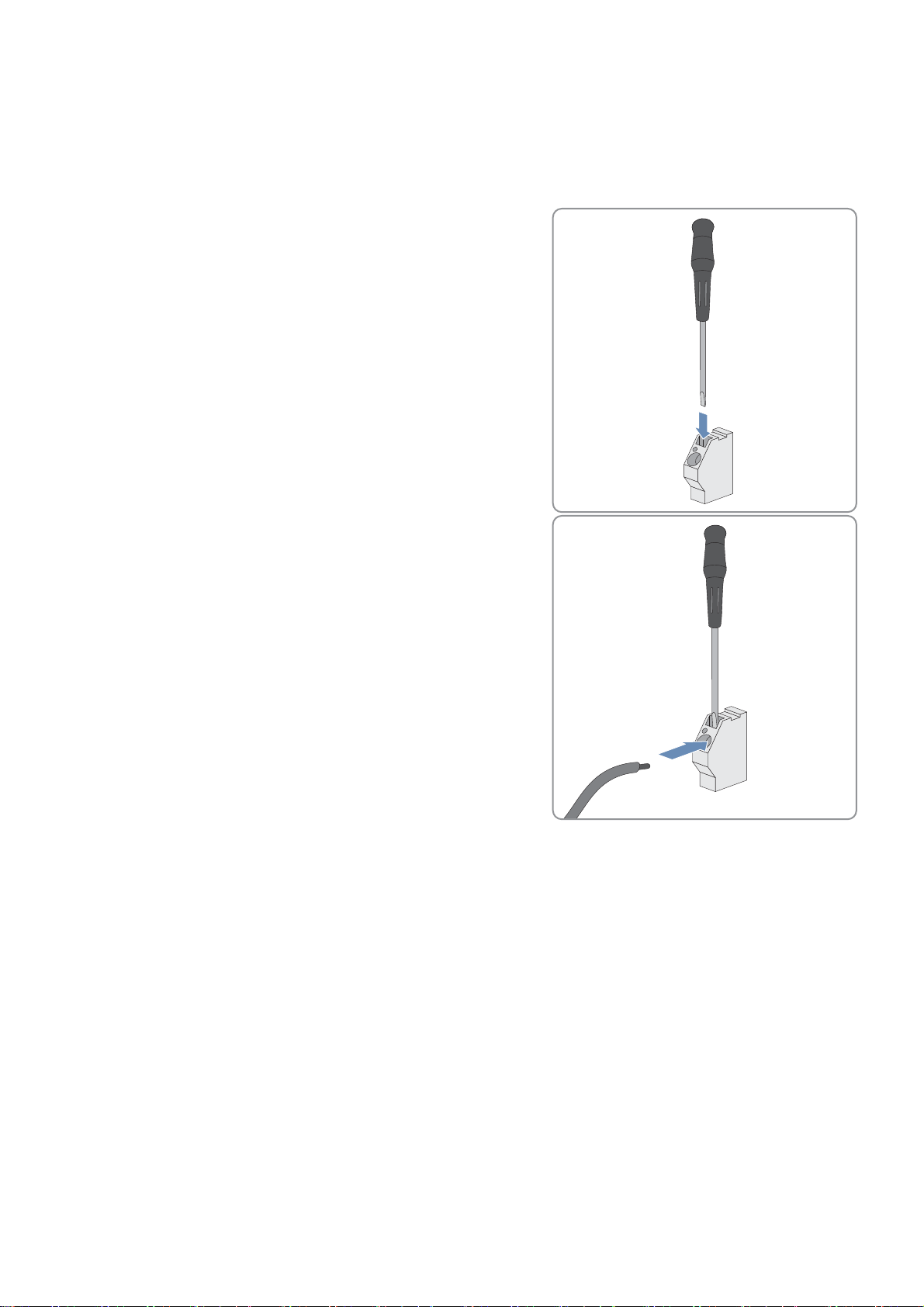
SMA Solar Technology AG 11 Periodic Actions
11.2 Clamp Connections
11.2.1 Connecting Insulated Conductors to Spring-Cage Terminals
Connect each insulated conductor to the corresponding spring-cage terminal as follows.
1. Insert the screwdriver into the clamping contact of the spring-cage
terminal.
2. Push the stripped insulated conductor as far as possible into the
terminal. Make sure that no insulation is trapped in the terminal.
3. Pull the screwdriver out of the clamping contact.
Operating Manual PPC-BE-P7-en-13 51
Page 52
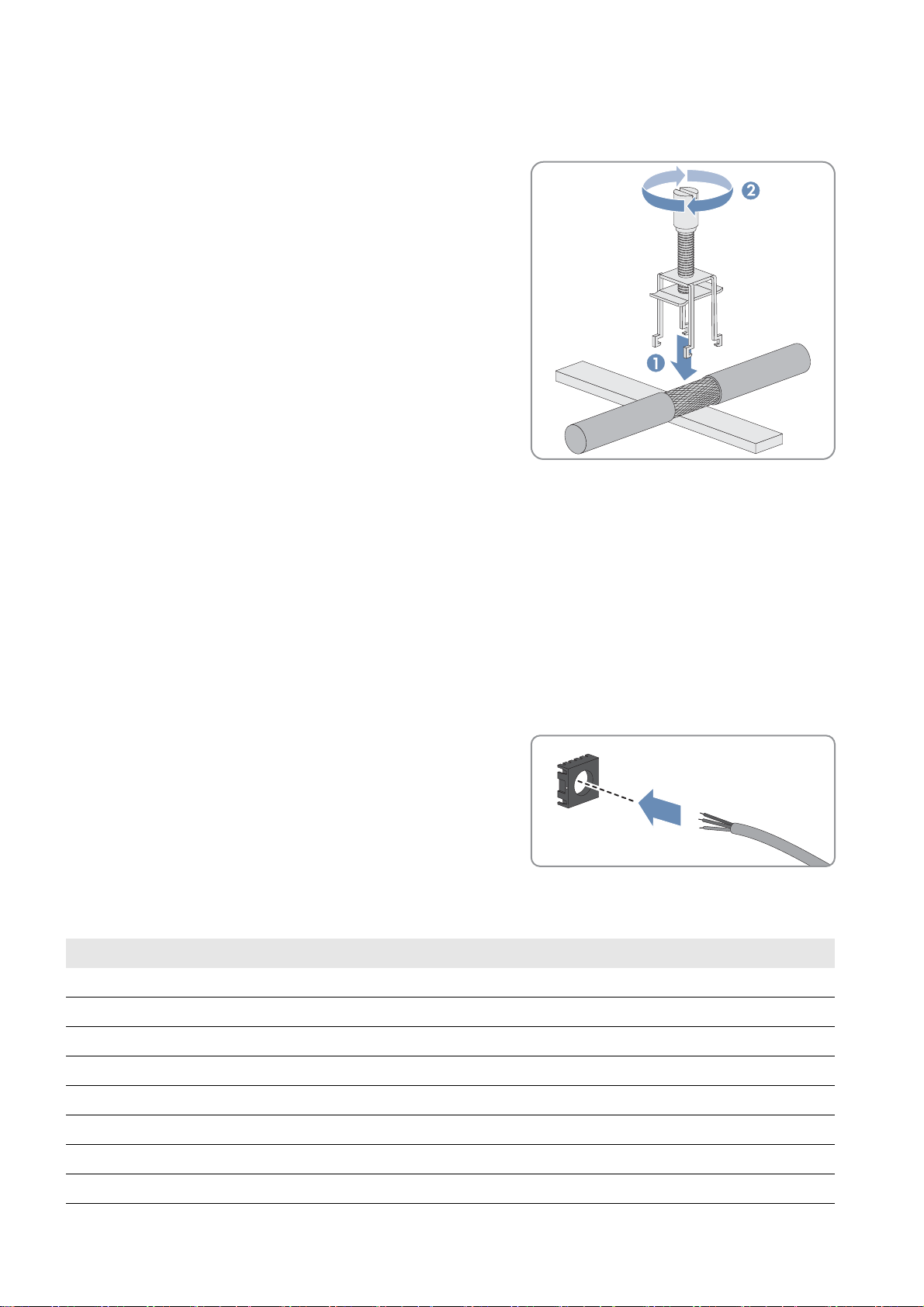
11 Periodic Actions SMA Solar Technology AG
11.2.2 Connecting the Shield Contact of the Cable Using a Shield Clamping Saddle
1. Remove the shield clamping saddle from the busbar.
2. Press the shield clamping saddle onto the shield of the stripped
cable until the shield clamping saddle snaps into place, and fasten
the shield clamping saddle hand-tight.
11.2.3 Installing Network Cables to the RJ45 Keystone Pin Connector
Optionally, you can connect the installation cables for the network to the modular patch panel. The module for the
network cables contains four or eight RJ45 Keystone pin connectors that are used to connect the network cables to the
keystone jacks.
Procedure:
1. Dismantle the network cable by 30 mm.
2. Fold the braided shielding.
3. Remove the foil shield from the insulated conductor pairs.
4. With the adhesive side facing the inside, attach the aluminum foil from the outside so that it is flush with the braided
shielding.
5. Lead the network cable through the cable organizer.
6. Insert the conductors into the slots of the cable organizer. Use the appropriate color coding according to the
standard of your choice.
Insulated conductor pair Insulated conductor color Contact-568A Contact-568B
1white/blue55
blue 4 4
2white/orange31
orange 6 2
3white/green13
green 2 6
4white/brown77
brown 8 8
52 PPC-BE-P7-en-13 Operating Manual
Page 53

SMA Solar Technology AG 11 Periodic Actions
7. Shorten protruding conductors.
8. Insert the cable organizer in the enclosure. Make sure that the
white arrow of the cable organizer is pointing towards the white
arrow on the enclosure.
☑ The cable organizer snaps into place.
9. Push the folding parts of the enclosure back together using a suitable pair of pliers (e.g. pipe wrench).
☑ The folding parts of the enclosure snap into place.
10. Secure the cable retainer of the enclosure with a cable tie.
11. Cut off the protruding end of the cable tie.
Operating Manual PPC-BE-P7-en-13 53
Page 54

11 Periodic Actions SMA Solar Technology AG
11.3 Settings on the User Interface
11.3.1 Logging Into the User Interface
11.3.1.1 Logging In at the Touch Display
1. Activate the touch display by tapping.
2. Select the respective user group in the field User identifier.
3. Enter the password in the field Password.
4. Select [Login].
11.3.1.2 Logging In on the Computer
You can activate the user interface of the Power Plant Controller via the system network. This enables visualization of the
system data and adjustment of device settings of the PV system and the Power Plant Controller on the computer. To access
the user interface, the web browser Firefox as of version 13 must be installed on your computer. Other Internet browsers
such as Chrome or Microsoft Internet Explorer can also be used. However, this may lead to deviations in the display.
Procedure:
1. Enter the IP address of the Power Plant Controller and press the enter key.
☑ The web browser will download the required Java Applet from the Power Plant Controller and will then start the
user interface.
☑ The start page of the user interface opens.
✖ The start page of the user interface does not open?
• Make sure that Java Runtime Environment is installed on your computer.
• Make sure that the Power Plant Controller is properly connected to the local network (see Section6.5
"Connecting Network Cables and Optical Fibers", page24).
• Make sure that the IP address has been entered correctly.
• After changes, especially to the network settings of the Power Plant Controller, wait approximately one minute
and then re-enter the IP address of the Power Plant Controller in a new browser window.
2. Select the respective user group in the field User identifier.
User group Password (default settings)
User 0000
Installer 1111
3. Enter the password in the Password field.
4. Select [Login].
11.3.2 Logging Out of the User Interface
By logging out of the user interface of the Power Plant Controller, you will protect your PV system from unauthorized
access. If you do not log out of the user interface, you will automatically be logged off from the user interface after
15 minutes of inactivity. This time interval can be adjusted by SMA Service, if required.
Procedure:
•Select [Logout] in the navigation bar.
54 PPC-BE-P7-en-13 Operating Manual
Page 55

SMA Solar Technology AG 12 Technical Data
12 Technical Data
Enclosure
Mounting type Wall mounting
Material Aluminum, powder-coated
Color of door RAL9006 (white aluminum)
Color of enclosure body RAL 7024 (graphite gray)
Lock cylinder Double-bit key for switch cabinet
Mechanical Data
Width x height x depth 720 mm x 1,125 mm x 325 mm
Maximum weight*
* depending on the option ordered
60 kg
Option-Dependent Features
Display*
Touch display, leading
Ethernet switch optional / managed / unmanaged
Maximum number of analog inputs 12
Maximum number of analog outputs 7
Maximum number of digital inputs 18
Maximum number of digital outputs 16
* for indoor mounting only
Voltage Supply
AC supply voltage 100 VAC to 240 VAC
DC supply voltage 36 VDC to 60 VDC
Power frequency 50 Hz / 60 Hz
Overvoltage category 2
Pre-fuse*
* depending on local directives, all poles must be connected
B16
Operating Manual PPC-BE-P7-en-13 55
Page 56

12 Technical Data SMA Solar Technology AG
Supported Products
Central inverters Sunny Central of the CP XT production series / Sunny Central
of the HE-20 production series / Sunny Central 2200 /
Sunny Central 2500
Maximum number of central inverters 200
Decentralized inverters Sunny Tripower via SMA Cluster Controller /
Sunny Tripower 60 via Inverter Manager
Maximum number of SMA Cluster Controllers and/or
20
Sunny Tripower 60
Transducer / network analyzer Ardetem TRM4
Janitza UMG 604 / UMG 605
Schneider Electric ION 8600 / ION 7550 / ION 7650
Schweitzer Engineering Laboratories SEL-735
Ambient Conditions
Degree of protection*
IP54
Operating temperature range ‒20°C to +50°C
Storage temperature range ‒40°C to +70°C
Relative humidity, non-condensing 10% to 95%
Snow load 85 kg/m
Maximum operating altitude above MSL**
* in accordance with IEC 60529
** without I/O enhancement 4,000 m
2,000 m
2
56 PPC-BE-P7-en-13 Operating Manual
Page 57

SMA Solar Technology AG 13 Appendix
13 Appendix
13.1 Structure of the System Network
Two networks can be connected to the Power Plant Controller. This means that the output values can be transmitted to
two PV system networks.
The Power Plant Controller delivers the output values for the Cluster Controllers and the output values for the
Sunny Centrals via separate LAN interfaces.
To ensure the correct transmission of the output values, the following rules must be observed:
• If Sunny Centrals and Cluster Controllers are installed in the system, we recommend that they are organized in
separate networks.
• If the Sunny Centrals and Cluster Controllers have to be operated in the same network, only one network can be
used for transmission of output values. In this case, the time interval for transmitting output values is extended to at
least the time interval determined for the Cluster Controller.
13.2 Principle of the Communication Network
The Power Plant Controller communicates with the connected devices, with the network analyzer, the grid operator, and
the SCADA system via Modbus protocol.
The Modbus protocol is a communication protocol that is based on a client-server architecture.
Figure16: Principle of the communication network of the PV system with Power Plant Controller (example)
13.3 Scaling of the Analog Measuring Channels
The Power Plant Controller can process both analog and digital measured values.
If a network analyzer is used, the measured values are scaled automatically.
Analog measured values are measured at the point of interconnection and converted by a transducer into values that the
Power Plant Controller can process. Since the transducer can deliver values for active power, reactive power, voltage or
frequency, the input values at the Power Plant Controller must be scaled. This is the only way that the
Power Plant Controller is able to convert into technical values and continue processing the measured values from the
values supplied by the transducer.
For scaling, the possible range of the converted values and the range of the measured values must be entered in the user
interface (see Section7.9 "Selecting the Signal Source and Adjusting the Scaling of Measured Values", page34).
Operating Manual PPC-BE-P7-en-13 57
Page 58

13 Appendix SMA Solar Technology AG
The range between x0 and x1 refers to the converted values. This range is dependent on the measurement signal used
and on the analog input to which the converted values are supplied.
Measurement signal Analog input Measurement range of
the analog signals
Standard signal voltage Onboard ‒10 V
10 V
Standard signal voltage Onboard 0 V
10 V
Standard signal current Onboard 0 mA
20 mA
Standard signal voltage Bus coupler ‒10 V
10 V
Standard signal voltage Bus coupler 0 V
10 V
Standard signal current Bus coupler 4 mA
20 mA
The range between y0 and y1 is the range into which the Power Plant Controller scales the converted values. This is
equivalent to the measurement range.
Within the measurement range is the range in which the valid measured values occur. The lower valid measured value
corresponds to yMin, the upper valid measured value corresponds to yMax
Range of the converted
values
x0 = ‒8,192
x1 = 8,192
x0 = 0
x1 = 8,192
x0 = 0
x1 = 7,367
x0 = ‒32,768
x1 = 32,767
x0 = 0
x1 = 32,767
x0 = 0
x1 = 32,767
Example: Scaling of analog input values
Analog voltage signals in the range from ‒10 V to +10 V are received at the analog input. The analog-to-digital
converter of the Power Plant Controller uses this to generate a digital signal in the range of ‒8.192 to +8.192. The
measured value processing in the Power Plant Controller calculates the reactive power value from this signal, and then
limits it to the permitted range from ‒15 MVAr to +15 MVAr.
Lower value for the range of valid measured values:
yMin = ‒20 MVAr
Lower signal value supplied by the transducer:
x0 = 8.192
Lower value of the measurement range:
y0 = ‒15 MVAr
Upper value for the range of valid measured values:
yMax = +20 MVAr
Upper signal value supplied by the transducer:
x1 = 8.192
Upper value of the measurement range:
y1 = +15 MVAr
58 PPC-BE-P7-en-13 Operating Manual
Page 59

SMA Solar Technology AG 13 Appendix
13.4 Output Value Specification Under Fault Conditions
If transmission of the setpoints under fault conditions is not possible via Modbus protocol, the Power Plant Controller uses
a substitution value or the last transmitted value. This is set for each specific system by SMA Service.
Basically, three communication errors are possible:
Error type Control of the
Power Plant Controller
The operator setpoints are not
received by the
Power Plant Controller.
Actual values from the network
analyzer are not received by the
Power Plant Controller.
Output value transmission to the
devices is disturbed
Once the error in transmitting the setpoints of the Power Plant Controller via Modbus protocol has been eliminated,
transmission of the output values calculated by the Power Plant Controller to the devices of the PV system automatically
recommences.
The output values are calculated with
the last valid setpoint or with a
substitution value.
New output values cannot be
calculated. The controller switches to
manual operation and transmits the
last valid output value or a substitution
value.
Depending on the parameterization,
the connected devices work with the
last valid output values received or
with a substitution value.
Parameterization
Parameterization is carried out at the
Power Plant Controller.
Parameterization is carried out at the
Power Plant Controller.
Parameterization is carried out at the
connected devices.
13.5 Directive for Secure Passwords
To protect the Power Plant Controller from unauthorized access, you must select a secure password.
SMA Solar Technology AG recommends choosing the password in accordance with the following directives:
• The password has at least five characters.
• The password consists of letters, at least one number, and at least one special character.
• The password does not contain umlauts.
13.6 Type Label
The type label clearly identifies the product. There are two type labels attached to the Power Plant Controller. The type
labels are located on the right-hand inside panel and on the right-hand outside panel of the Power Plant Controller.
You will find the following information on the type label:
•Device type
• Option code
•Serial number
• Production version
• Device-specific characteristics
You will require the information on the type label to use the product safely and when seeking customer support from the
SMA Service Line.
Operating Manual PPC-BE-P7-en-13 59
Page 60

13 Appendix SMA Solar Technology AG
Symbols on the Type Label
Symbol Explanation
CE marking
The product complies with the requirements of the applicable EU directives.
Degree of protection
The product is protected against interior dust deposits and splashing water from all angles.
WEEE designation
Do not dispose of the product together with the household waste but in accordance with the locally
applicable disposal regulations for electronic waste.
60 PPC-BE-P7-en-13 Operating Manual
Page 61

SMA Solar Technology AG 14 Contact
14 Contact
If you have technical problems with our products, please contact the SMA Service Line. We require the following
information in order to provide you with the necessary assistance:
•Device type
• Serial number of the Power Plant Controller
•Error message
Australia SMA Australia Pty Ltd.
Sydney
Toll free for Australia: 1800 SMA AUS
(1800 762 287)
International: +61 2 9491 4200
Argentina
Brasil
Chile
SMA South America SPA
Santiago
+562 2820 2101
Perú
Danmark
Deutschland
Österreich
Schweiz
SMA Solar Technology AG
Niestetal
SMA Online Service Center:
www.SMA.de/Service
Sunny Boy, Sunny Mini Central,
Sunny Tripower: +49 561 9522-1499
Monitoring Systems
(Kommunikationsprodukte): +49 561
9522-2499
Fuel Save Controller (PV-Diesel Hybridsysteme): +49 561 9522-3199
Sunny Island, Sunny Backup,
Hydro Boy: +49 561 9522-399
Belgien
Belgique
België
SMA Benelux BVBA/SPRL
Mechelen
+32 15 286 730
Luxemburg
Luxembourg
Nederland
Česko
Magyarország
Polska
SMA Central & Eastern Europe s.r.o.
Praha
+420 235 010 417
România
Slovensko
France SMA France S.A.S.
Lyon
Sunny Boy, Sunny Mini Central,
Sunny Tripower : +33 472 09 04 40
Monitoring Systems :
+33 472 09 04 41
Sunny Island : +33 472 09 04 42
Sunny Central : +33 472 09 04 43
Sunny Central: +49 561 9522-299
España
Portugal
SMA Ibérica Tecnología Solar, S.L.U.
Barcelona
+34 935 63 50 99
South Africa SMA Solar Technology
South Africa Pty Ltd.
Centurion (Pretoria)
08600 SUNNY (08600 78669)
India SMA Solar India Pvt. Ltd.
Mumbai
+91 22 61713888
Ελλάδα
Κύπρος
Kıbrıs
SMA Hellas AE
Αθήνα
+30 210 9856666
България
International: +27 (12) 622 3000
Italia SMA Italia S.r.l.
Milano
+39 02 8934-7299
United Kingdom SMA Solar UK Ltd.
Milton Keynes
+44 1908 304899
Operating Manual PPC-BE-P7-en-13 61
Page 62

14 Contact SMA Solar Technology AG
!
SMA Solar (Thailand) Co., Ltd.
+66 2 670 6999
SMA Middle East LLC
+971 2 234-6177
대한민국 SMA Technology Korea Co., Ltd.
서울
+82-2-520-2666
Other countries International SMA Service Line
Niestetal
Toll free worldwide:
00800 SMA SERVICE
(+800 762 7378423)
62 PPC-BE-P7-en-13 Operating Manual
Page 63

Page 64

SMA Solar Technology
www.SMA-Solar.com
 Loading...