

Page 1
US
Sunny Boy Accessories
SMA POWER BALANCER
Installation Guide
SBUS-PowBal-IUS102810 | IMUS-SBUS-PBL | Version 1.0
Page 2

Page 3

SMA America, LLC Legal Restrictions
Copyright © 2010 SMA America,LLC. All rights reserved.
No part of this document may be reproduced, stored in a retrieval system, or transmitted, in any form
or by any means, electronic, mechanical, photographic, magnetic or otherwise, without the prior
written permission of SMA America,LLC.
SMA America,LLC makes no representations, express or implied, with respect to this documentation
or any of the equipment and/or software it may describe, including (with no limitation) any implied
warranties of utility, merchantability, or fitness for any particular purpose. All such warranties are
expressly disclaimed. Neither SMA America,LLC nor its distributors or dealers shall be liable for any
indirect, incidental, or consequential damages under any circumstances.
(The exclusion of implied warranties may not apply in all cases under some statutes, and thus the
above exclusion may not apply.)
Specifications are subject to change without notice. Every attempt has been made to make this
document complete, accurate and up-to-date. Readers are cautioned, however, that
SMAAmerica,LLC reserves the right to make changes without notice and shall not be responsible for
any damages, including indirect, incidental or consequential damages, caused by reliance on the
material presented, including, but not limited to, omissions, typographical errors, arithmetical errors
or listing errors in the content material.
All trademarks are recognized even if these are not marked separately. Missing designations do not
mean that a product or brand is not a registered trademark.
The Bluetooth
®
word mark and logos are registered trademarks owned by Bluetooth SIG, Inc. and
any use of such marks by SMA America,LLC is under license.
SMA America, LLC
3801 N. Havana Street
Denver, CO 80239 U.S.A.
Installation Guide SBUS-PowBal-IUS102810 3
Page 4
Important Safety Instructions SMA America, LLC
IMPORTANT SAFETY INSTRUCTIONS
SAVE THESE INSTRUCTIONS
This manual contains important instructions for SMA Power Balancer accessory, that must be followed
during installation and maintenance of the accessory.
The SMA Power Balancer is designed and tested according to international safety requirements, but
as with all electrical and electronic equipment, certain precautions must be observed when installing
and/or operating the SMA Power Balancer. To reduce the risk of personal injury and to ensure the
safe installation and operation of the SMA Power Balancer, you must carefully read and follow all
instructions, cautions and warnings in this installation guide.
Warnings in this document
A warning describes a hazard to equipment or personnel. It calls attention to a procedure or practice,
which, if not correctly performed or adhered to, could result in damage to or destruction of part or all
of the SMA equipment and/or other equipment connected to the SMA equipment or personal injury.
DANGER
DANGER indicates a hazardous situation which, if not avoided, will result in death or
serious injury.
WARNING
WARNING indicates a hazardous situation which, if not avoided, could result in death or
serious injury.
CAUTION
CAUTION indicates a hazardous situation which, if not avoided, could result in minor or
moderate injury.
NOTICE
NOTICE is used to address practices not related to personal injury.
4 SBUS-PowBal-IUS102810 Installation Guide
Page 5

SMA America, LLC Important Safety Instructions
Other symbols in this document
In addition to the safety and hazard symbols described on the previous pages, the following symbol
is also used in this installation guide:
Information
This symbol accompanies notes that call attention to supplementary information that you
must know and use to ensure optimal operation of the system.
Installation Guide SBUS-PowBal-IUS102810 5
Page 6
General Warnings SMA America, LLC
General Warnings
General Warnings
All electrical installations must be done in accordance with all local electrical codes and
the National Electrical Code
®
, ANSI/NFPA 70. For installation in Canada the installations
must be done in accordance with applicable Canadian standards.
The SMA Power Balancer contains no user-serviceable parts. For all repair and
maintenance, always return the unit to an authorized SMA Service Center.
Before installing or using the SMA Power Balancer, read all of the instructions, cautions,
and warnings on the SMA Power Balancer in this installation guide.
Wiring of the SMA Power Balancer must be made by qualified personnel only.
6 SBUS-PowBal-IUS102810 Installation Guide
Page 7

SMA America, LLC Table of Contents
Table of Contents
1 Notes on this manual. . . . . . . . . . . . . . . . . . . . . . . . . . . . . . 9
1.1 Validity . . . . . . . . . . . . . . . . . . . . . . . . . . . . . . . . . . . . . . . . . . . . 9
1.2 Target group . . . . . . . . . . . . . . . . . . . . . . . . . . . . . . . . . . . . . . . . 9
1.3 Nomenclature. . . . . . . . . . . . . . . . . . . . . . . . . . . . . . . . . . . . . . . 9
2 Safety . . . . . . . . . . . . . . . . . . . . . . . . . . . . . . . . . . . . . . . . . 10
2.1 Appropriate usage . . . . . . . . . . . . . . . . . . . . . . . . . . . . . . . . . . 10
2.2 Safety instructions . . . . . . . . . . . . . . . . . . . . . . . . . . . . . . . . . . . 10
3 Scope of delivery . . . . . . . . . . . . . . . . . . . . . . . . . . . . . . . . 11
4 Grid feeding with the SMA Power Balancer . . . . . . . . . . 12
5 Configuration . . . . . . . . . . . . . . . . . . . . . . . . . . . . . . . . . . . 14
5.1 Configuration options . . . . . . . . . . . . . . . . . . . . . . . . . . . . . . . . 14
5.1.1 Off . . . . . . . . . . . . . . . . . . . . . . . . . . . . . . . . . . . . . . . . . . . . . . . . . . . . . .15
5.1.2 Power Guard . . . . . . . . . . . . . . . . . . . . . . . . . . . . . . . . . . . . . . . . . . . . .15
5.1.3 Phase Guard . . . . . . . . . . . . . . . . . . . . . . . . . . . . . . . . . . . . . . . . . . . . . . 16
5.1.4 Fault Guard . . . . . . . . . . . . . . . . . . . . . . . . . . . . . . . . . . . . . . . . . . . . . . .17
6 Wiring . . . . . . . . . . . . . . . . . . . . . . . . . . . . . . . . . . . . . . . . . 18
6.1 Connecting
SB 5000-US/SB 6000-US/SB 7000-US/SB 8000-US . . . . . . 18
6.2 Connecting
SB 8000TL-US/SB 9000TL-US/SB 10000TL-US . . . . . . . . . . . 21
7 Testing the function . . . . . . . . . . . . . . . . . . . . . . . . . . . . . . 25
8 Contact . . . . . . . . . . . . . . . . . . . . . . . . . . . . . . . . . . . . . . . . 26
Installation Guide SBUS-PowBal-IUS102810 7
Page 8

Page 9

SMA America, LLC Notes on this manual
1 Notes on this manual
1.1 Validity
This installation guide describes the assembly, installation, configuration and commissioning of the
SMAPowerBalancer. This manual does not cover any details concerning connected inverters and
other equipment.
1.2 Target group
This manual is for qualified personnel. Qualified personnel have received training and have
demonstrated skills and knowledge in the construction and operation of this device. Qualified
personnel are trained to deal with the dangers and hazards involved in installing electric devices.
1.3 Nomenclature
In this document SMA America Production, LLC is referred to in the following as SMA.
The nomenclature specified here for menus and parameters applies throughout the entire manual.
Installation Guide SBUS-PowBal-IUS102810 9
Page 10

Safety SMA America, LLC
2 Safety
2.1 Appropriate usage
The SMA Power Balancer can only be used in combination with the following types of inverter:
• Sunny Boy 5000-US
• Sunny Boy 6000-US
• Sunny Boy 7000-US
• Sunny Boy 8000-US
• Sunny Boy 8000TL-US (SB 8000TLUS-10)
• Sunny Boy 9000TL-US (SB 9000TLUS-10)
• Sunny Boy 10000TL-US (SB10000TLUS-10)
The installation method will vary with the different types of inverters.
Read this installation guide carefully.
Also refer to the installation guide of the appropiate inverter.
Always use the SMA Power Balancer for linking 3 inverters. The unbalanced load between the 3
inverters must not be greater than the prescribed maximum unbalanced load of the utility grid.
Do not use the SMAPowerBalancer in combination with other inverters and for other purposes than
described in this manual.
2.2 Safety instructions
DANGER
High voltages are present in the inverter during operation.
Death or serious injury due to electric shock.
• All work on the inverter must only be carried out by qualified personnel.
10 SBUS-PowBal-IUS102810 Installation Guide
Page 11

SMA America, LLC Scope of delivery
3 Scope of delivery
Position Number Description
A 3 Spring clamp male connector
B 1Jumper
C 2 Power Balancer cable
D 4Cable gland
E 4 Lock nut for gable gland
F 1 Installation guide
Installation Guide SBUS-PowBal-IUS102810 11
Page 12

Grid feeding with the SMA Power Balancer SMA America, LLC
4 Grid feeding with the SMA Power Balancer
The SMA Power Balancer enables a circuit connection of 3 inverters to a three-phase grid-feed
system.
Connection to a three-phase system, 208V/240V
• One inverter connected to L1, L2 and N, if present.
• One inverter connected to L2, L3 and N, if present.
• One inverter connected to L1, L3 and N, if present.
Connection to a three-phase system, 277V
• One inverter connected to L1 and N.
• One inverter connected to L2 and N.
• One inverter connected to L3 and N.
12 SBUS-PowBal-IUS102810 Installation Guide
Page 13

SMA America, LLC Grid feeding with the SMA Power Balancer
Adjusting reaction to device fault and grid fault
By activating this Power Balancer feature, you can stipulate how the other two inverters are to react
if there is a device fault with the third inverter or there is a grid voltage fault.
Three-phase grid connection
For further information on three-phase grid connection refer to the download area at
www.SMA-America.com.
The connections for the SMA Power Balancer are galvanically isolated from the rest of the inverter
circuit.
Installation Guide SBUS-PowBal-IUS102810 13
Page 14

Configuration SMA America, LLC
5 Configuration
The SMA Power Balancer is deactivated at the factory using the parameter "PowerBalancer"
(parameter setting = off).
The SMA Power Balancer can only be activated and configured using a communication
device.
• Ensure that a communication device is installed in the Sunny Boy inverters you want
operate with the SMA Power Balancer.
5.1 Configuration options
There are 4 different configuration options for the "PowerBalancer" parameter.
•Off
•Power Guard
•Phase Guard
•Fault Guard
Local connection requirements
Select the respective setting and always observe the local connection requirements and
provisions of your utility operator.
14 SBUS-PowBal-IUS102810 Installation Guide
Page 15

SMA America, LLC Configuration
5.1.1 Off
The SMA Power Balancer is deactivated at the factory.
– In the event of a grid voltage fault or device fault of an inv erter, only the affected inverter
disconnects from the grid. The other two inverters continue to run at an undiminished power
level.
5.1.2 Power Guard
Select this setting if, in the event of a failure, the unbalanced load should be limited to a defined
value over a 10-minute average.
If one of the three inverters indicates a grid voltage fault or device fault and stops feeding
in, the other two inverters automatically limit their power to a defined value over a 10 minute
average.
Installation Guide SBUS-PowBal-IUS102810 15
Page 16

Configuration SMA America, LLC
5.1.3 Phase Guard
This operating mode enables the implementation of three-phase grid voltage monitoring.
– If one of the 3 inverters indicates a grid voltage fault and stops feeding in, the other two
inverters also disconnect from the grid automatically.
– If one of the 3 inverters indicates a device fault and stops feeding in, the other two inverters
are not affected and continue to feed in at full power.
16 SBUS-PowBal-IUS102810 Installation Guide
Page 17

SMA America, LLC Configuration
5.1.4 Fault Guard
This operating mode enables the implementation of three-phase grid voltage monitoring that
also reacts to device failures.
– If one of the 3 inverters indicates a grid voltage fault and stops feeding in, the other two
inverters also disconnect from the grid immediately.
– If one of the 3 inverters indicates a device fault and stops feeding in, the other two inverters
also disconnect from the grid with a delay of 5 minutes.
Installation Guide SBUS-PowBal-IUS102810 17
Page 18

Wiring SMA America, LLC
6 Wiring
6.1 Connecting SB 5000-US/SB 6000-US/SB 7000-US/SB 8000-US
Installation overview
If the provided Power Balancer cable ist too short, it can be extended.
• The maximum length must not exceed 928ft. (300m).
Object Description
A Screw terminal block
B Jumper slot
C Power Balancer cable
18 SBUS-PowBal-IUS102810 Installation Guide
Page 19

SMA America, LLC Wiring
1. Open the 2 outside inverters as described in the Sunny Boy installation guide.
2. Remove 1 filler plug on the bottom right of the 2 outside inverters.
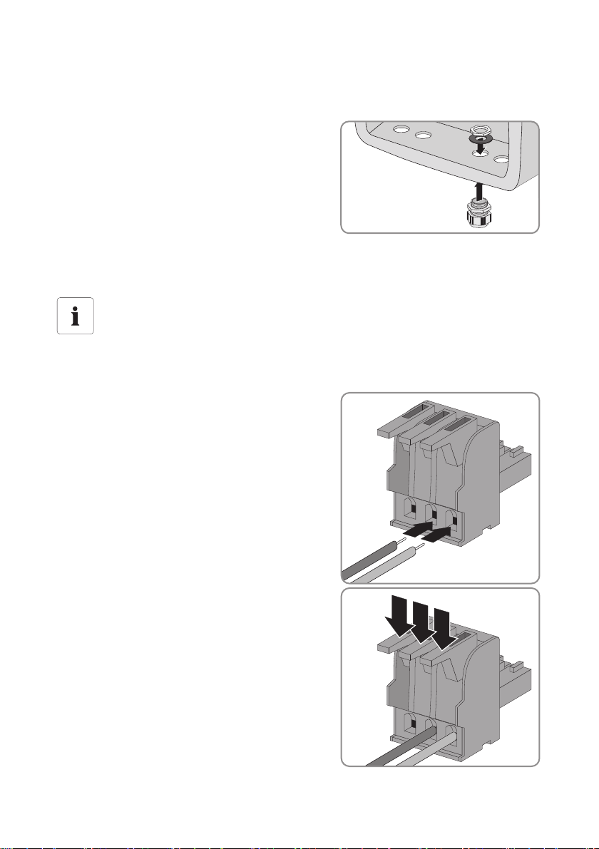
3. Insert cable glands into each opening and fasten
each with a lock nut.
4. Unscrew the cap nut of the installed cable glands a bit.
5. Thread a Power Balancer cable(C) through the cable glands into the 2 outside inverters.
Only use the cable end with the separate shield flat connector.
6. Draw each Power Balancer cable up to the screw terminal block (A).
7. Tighten the cap nut of each cable gland in order to secure the Power Balancer cable.
8. Connect the conductors of the Power Balancer cable
(C) to the screw terminal block (A).
– Red conductor to terminal +.
– Blue conductor to terminal − .
Linking the 3 inverters at the middle inverter
9. Open the middle inverter as described in the Sunny Boy installation guide.
10. Remove 2 filler plugs on the bottom right of the middle inverter.
11. Insert cable glands into each opening and fasten
each with a lock nut.
12. Unscrew the cap nut of the installed cable glands a bit.
13. Thread the Power Balancer cables from the 2 outside inverters through the cable glands into the
middle inverter.
Only use 1 cable gland per cable.
14. Draw both Power Balancer cables up to the screw terminal block (A).
Installation Guide SBUS-PowBal-IUS102810 19
Page 20

Wiring SMA America, LLC
15. Connect the conductors of both Power Balancer
cables to the screw terminal block.
– Both red conductors to terminal +.
– Both blue conductors to terminal − .
16. Install the jumper to the middle inverter
on position (1) of the jumper slot (B).
Connecting the shield wire at the 2 outside inverters
Position Description
A Grounding flat pin
B Shield flat connector
17. Connect the shield flat connector (B) of the
Power Balancer cable to the grounding flat pin (A).
18. Close all 3 inverters as described in the Sunny Boy
installation guide.
20 SBUS-PowBal-IUS102810 Installation Guide
Page 21

SMA America, LLC Wiring
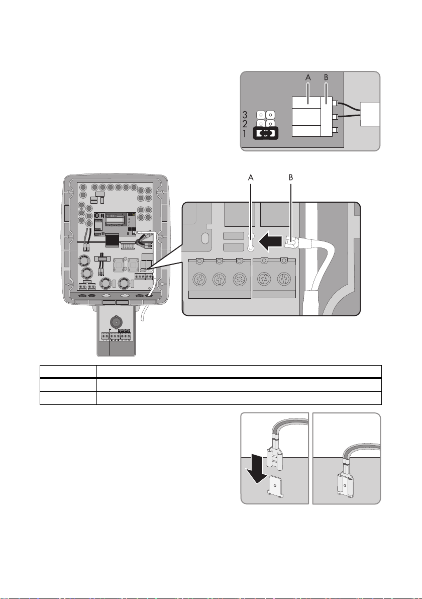
6.2 Connecting SB 8000TL-US/SB 9000TL-US/SB 10000TL-US
Installation overview
If the provided Power Balancer cable ist too short, it can be extended.
• The maximum length must not exceed 928ft. (300m).
Position Description
A Three-pole terminal block
B Spring clamp male connector
C Power Balancer cable
Installation Guide SBUS-PowBal-IUS102810 21
Page 22
Wiring SMA America, LLC
1. Open the 2 outside inverters as described in the Sunny Boy installation guide.
2. Remove 1 filler plug on the bottom right of the 2 outside inverters.
3. Insert cable glands into each opening and fasten
each with a lock nut.
4. Unscrew the cap nut of the installed cable glands a bit.
5. Thread a Power Balancer cable (C) through the cable glands into the 2 outside inverters.
Only use the cable end with the separate shield flat connector.
6. Draw each cable up to the three-pole terminal block (A).
7. Tighten the cap nut of each cable gland in order to secure the Power Balancer cable.
8. Insert the conductors of the Power Balancer cable
into the spring clamp male connector.
– Red conductor into the middle terminal.
– Blue conductor into the right terminal.
– The left terminal remains unused.
9. Close all clamp terminals by pushing down the
levers.
10. Plug the spring clamp male connector (B) to the
three-pole terminal block (A).
22 SBUS-PowBal-IUS102810 Installation Guide
Page 23

SMA America, LLC Wiring
Linking the 3 inverters at the middle inverter
11. Open the middle inverter as described in the Sunny Boy installation guide.
12. Remove 2 filler plugs on the bottom right of the middle inverter.
13. Insert cable glands into each opening and fasten
each with a lock nut.
14. Unscrew the cap nut of the installed cable glands a bit.
15. Thread the Power Balancer cables from the 2 outside inverters through the cable glands into the
middle inverter.
Only use 1 cable gland per cable.
16. Draw each cable up to the three-pole terminal block (A).
17. Tighten the cap nut of each cable gland in order to secure the Power Balancer cable.
18. Insert the conductors of both Power Balancer
cables into 1 spring clamp male connector.
– Both red conductors into the middle terminal.
– Both blue conductors into the right terminal.
– The left terminal remains unused.
19. Close all clamp terminals by pushing down the
levers.
Installation Guide SBUS-PowBal-IUS102810 23
Page 24
Wiring SMA America, LLC
20. Plug the spring clamp male connector (B) to the three-pole terminal block (A).
21. Install the jumper to the middle inverter
on position (1) of the jumper slot.
Connecting the shield wire at the 2 outside inverters
Position Description
A Grounding flat pin
B Shield flat connector
22. Connect the shield flat connector (B) of the
Power Balancer cable to the grounding flat pin (A).
23. Close all 3 inverters as described in the Sunny Boy installation guide.
24 SBUS-PowBal-IUS102810 Installation Guide
Page 25

SMA America, LLC Testing the function
E-today 0Wh
Mode MPP
Disturbance
PowerBalance
Disturbance
Vac-Bfr
Disturbance
PowerBalance
7 Testing the function
Check if the SMA Power Balancer operates correctly:
1. Select the "PhaseGuard" setting of the
"PowerBalancer" parameter for all three inverters.
2. Check whether all inverters in the group are feeding
the grid normally.
☑ If the green LED lights up steadily or if the
following display message appears, proceed
with point 3.
or
☑ If all inverters in this group show the adjacent
display message: Check the installation of the
SMA Power Balancer and contact the SMA
Serviceline if necessary.
3. Switch off the line circuit breaker for one of the
three inverters.
☑ The inverter with a deactivated line circuit
breaker indicates a grid voltage showing
following display message ("Bfr" and "Srr" are
irrelevant).
☑ The remaining inverters then also disconnect
from the grid showing following display
message.
☑ Both inverters subsequently switch to
"Balanced" mode.
☑ If the inverters react as described above, the
functionality test has been completed successfully.
Otherwise, check the configuration.
4. If applicable, reset the "PowerBalancer" parameter
to the desired setting in all inverters.
5. Switch on the line circuit breaker again.
6. The functionality test has been completed.
Installation Guide SBUS-PowBal-IUS102810 25
Page 26

Contact SMA America, LLC
8 Contact
If you have technical problems concerning our products, contact your ins tal ler or th e SM A Se rviceli ne.
We require the following information in order to provide you with the necessary assistance:
• Inverter type
• Type and number of modules connected
•Communication method
• Serial number of the Sunny Boy
• Failure or warning number of the Sunny Boy
• Display of the Sunny Boy
SMA Solar Technology America, LLC
6020 West Oaks Blvd
Rocklin, CA 95765
Tel. +1 916 625 0870
Tel. +1 877-MY SMA TECH
Tel. +1 877 697 6283 (Toll free, available for USA, Canada and Puerto Rico)
Fax +1 916 625 0871
Service@SMA-America.com
www.SMA-America.com
26 SBUS-PowBal-IUS102810 Installation Guide
Page 27

Page 28

4.""NFSJDB--$
XXX4.""NFSJDBDPN
 Loading...