

Page 1
SMA Plug-in Grounding
Anleitung zur Installation des Erdungssets SMA Plug-in Grounding
in einen SunnyBoy 2000HF/2500HF/3000HF.
Instructions for the installation of the SMA Plug-in Grounding set in
a Sunny Boy 2000HF/2500HF/3000HF.
Instructions pour l’installation du kit de mise à la terre SMA Plug-in
Grounding dans un Sunny Boy 2000HF/2500HF/3000HF.
Instrucciones para instalar el kit de puesta a tierra SMA Plug-in
Grounding en un Sunny Boy 2000HF/2500HF/3000HF.
Istruzioni per l'installazione del kit di messa a terra SMA Plug-in
Grounding in Sunny Boy 2000HF/2500HF/3000HF.
Manual para a instalação do kit de ligação à terra SMA Plug-in
Grounding num Sunny Boy 2000HF/2500HF/3000HF.
Handleiding voor de installatie van de aardingsset SMA Plug-in
Grounding in een Sunny Boy 2000HF/2500HF/3000HF.
Οδηγίες για την εγκατάσταση του σετ γείωσης SMA Plug-in
Grounding σε ένα Sunny Boy 2000HF/2500HF/3000HF.
Seite 3
Page 22
Page 42
Página 62
Pagina 82
Página 102
Pagina 122
Σελίδα 142
Návod k instalaci uzemňovací sady SMA Plug-in Grounding ve
střídači Sunny Boy 2000HF/2500HF/3000HF.
Sunny Boy 2000HF/2500HF/3000HF 내 SMA Plug-in
Grounding 세트 설치 지침
Erdung_HF-IXX105020 | IMXX-ERDUNG_SBHF | Version 2.0
Strana 162
페 182 지
Page 2

Page 3

SMA Solar Technology AG Inhaltsverzeichnis
Inhaltsverzeichnis
1 Hinweise zu dieser Anleitung . . . . . . . . . . . . . . . . . . . . . . . 4
1.1 Gültigkeitsbereich . . . . . . . . . . . . . . . . . . . . . . . . . . . . . . . . . . . . 4
1.2 Zielgruppe . . . . . . . . . . . . . . . . . . . . . . . . . . . . . . . . . . . . . . . . . 4
1.3 Weiterführende Information . . . . . . . . . . . . . . . . . . . . . . . . . . . . 4
1.4 Verwendete Symbole . . . . . . . . . . . . . . . . . . . . . . . . . . . . . . . . . 5
2 Sicherheit . . . . . . . . . . . . . . . . . . . . . . . . . . . . . . . . . . . . . . . 6
2.1 Bestimmungsgemäße Verwendung. . . . . . . . . . . . . . . . . . . . . . . 6
2.2 Sicherheitshinweise . . . . . . . . . . . . . . . . . . . . . . . . . . . . . . . . . . . 7
3 Lieferumfang. . . . . . . . . . . . . . . . . . . . . . . . . . . . . . . . . . . . . 8
4 SMA Plug-in Grounding installieren . . . . . . . . . . . . . . . . . . 9
5 Sicherung des SMA Plug-in Grounding prüfen und
austauschen . . . . . . . . . . . . . . . . . . . . . . . . . . . . . . . . . . . . 11
6 Parameter und Fehlermeldungen. . . . . . . . . . . . . . . . . . . 14
6.1 Einstellbare Parameter . . . . . . . . . . . . . . . . . . . . . . . . . . . . . . . 14
6.1.1 Parameter „Modul-Erdung vorgeschrieben?“ bzw. „GndMdt“ . . . . . . . . . . 14
6.1.2 Parameter „Vorgeschriebene Art der Erdung“ bzw. „Md.GndModReq“. . . 15
6.2 Fehlermeldungen . . . . . . . . . . . . . . . . . . . . . . . . . . . . . . . . . . . 16
6.3 Fehler beheben. . . . . . . . . . . . . . . . . . . . . . . . . . . . . . . . . . . . . 18
6.3.1 Sicherheit. . . . . . . . . . . . . . . . . . . . . . . . . . . . . . . . . . . . . . . . . . . . . . . . . . . . 18
6.3.2 Störung der Erdungssicherung beheben . . . . . . . . . . . . . . . . . . . . . . . . . . . . 18
6.3.3 Isolationsfehler beheben . . . . . . . . . . . . . . . . . . . . . . . . . . . . . . . . . . . . . . . . 19
6.3.4 Erdungsart korrigieren. . . . . . . . . . . . . . . . . . . . . . . . . . . . . . . . . . . . . . . . . . 19
7 Kontakt . . . . . . . . . . . . . . . . . . . . . . . . . . . . . . . . . . . . . . . . 20
Installationsanleitung Erdung_HF-IXX105020 3
Page 4

Hinweise zu dieser Anleitung SMA Solar Technology AG
1 Hinweise zu dieser Anleitung
1.1 Gültigkeitsbereich
Diese Anleitung beschreibt den Anschluss des Erdungssets SMA Plug-in Grounding und den
Austausch der Sicherungen im SMA Plug-in Grounding.
Sie dürfen das SMA Plug-in Grounding nur bei folgenden SMA Wechselrichtern einsetzen:
• Sunny Boy 2000HF (SB 2000HF-30),
• Sunny Boy 2500HF (SB 2500HF-30),
• Sunny Boy 3000HF (SB 3000HF-30).
Bewahren Sie diese Anleitung jederzeit zugänglich auf.
1.2 Zielgruppe
Diese Anleitung ist für ausgebildete Elektrofachkräfte. Die in dieser Anleitung beschriebenen
Tätigkeiten dürfen nur ausgebildete Elektrofachkräfte ausführen.
1.3 Weiterführende Information
Detaillierte Informationen zur Installation, Inbetriebnahme, Wartung und Fehlersuche des
Wechselrichters finden Sie in der jeweiligen Installationsanleitung.
4 Erdung_HF-IXX105020 Installationsanleitung
Page 5
SMA Solar Technology AG Hinweise zu dieser Anleitung
1.4 Verwendete Symbole
In dieser Anleitung werden folgende Arten von Sicherheitshinweisen und allgemeine Hinweise
verwendet:
GEFAHR!
G
„GEFAHR“ kennzeichnet einen Sicherheitshinweis, dessen Nichtbeachtung unmittelbar
zum Tod oder zu schwerer Körperverletzung führt!
WARNUNG!
„WARNUNG“ kennzeichnet einen Sicherheitshinweis, dessen Nichtbeachtung zum Tod
oder zu schwerer Körperverletzung führen kann!
VORSICHT!
„VORSICHT“ kennzeichnet einen Sicherheitshinweis, dessen Nichtbeachtung zu einer
leichten oder mittleren Körperverletzung führen kann!
ACHTUNG!
„ACHTUNG“ kennzeichnet einen Sicherheitshinweis, dessen Nichtbeachtung zu
Sachschäden führen kann!
Hinweis
Ein Hinweis kennzeichnet Informationen, die für den optimalen Betrieb des Produktes
wichtig sind.
☑ Dieses Symbol kennzeichnet ein Handlungsergebnis.
Installationsanleitung Erdung_HF-IXX105020 5
Page 6

Sicherheit SMA Solar Technology AG
2 Sicherheit
2.1 Bestimmungsgemäße Verwendung
Wenn Sie spezielle Zelltechnologien in Ihrem PV-Generator einsetzen, z. B. Dünnschicht- oder
rückseitenkontaktierte PV-Module, kann es notwendig sein, entweder den positiven oder den
negativen Pol der PV-Anlage zu erden. Mit dem SMA Plug-in Grounding lässt sich der PV-Generator
im Wechselrichter erden. Das steckbare Erdungsset eignet sich für Wechselrichter des Typs
SB2000HF-30, SB2500HF-30 und SB3000HF-30. Durch diese geräteinterne Erdung wird ein
langfristig sicherer Betrieb bei optimalen EMV-Eigenschaften und eine Minimierung der
Installationskosten erreicht.
Das SMA Plug-in Grounding enthält eine 1A‑Sicherung als Schutz gegen Brandgefahr und eine
Schaltung, die die Isolationsüberwachung des Wechselrichters auf das SMA Plug-in Grounding
abstimmt. Das SMA Plug-in Grounding stellt über die Sicherung eine direkte Verbindung zwischen
dem zu erdenden Pol (Plus oder Minus) der PV-Module und dem PE-Anschluss des Wechselrichters
her. Wenn ein Erdschluss auftritt, unterbricht die Sicherung im SMA Plug-in Grounding den
Fehlerstrom.
Informationen über Art und Notwendigkeit der Modulerdung in Ihrer PV-Anlage erhalten Sie von
Ihrem Modulhersteller.
Der Wechselrichter darf nur an PV-Generatoren (Module und Verkabelung) betrieben werden, die
schutzisoliert aufgebaut sind (Schutzklasse II).
Das SMA Plug-in Grounding ist ausschließlich zur Verwendung in den SMA Wechselrichtern des Typs
SunnyBoy 2000HF/2500HF/3000HF geeignet.
6 Erdung_HF-IXX105020 Installationsanleitung
Page 7
SMA Solar Technology AG Sicherheit
2.2 Sicherheitshinweise
GEFAHR!
Lebensgefahr durch hohe Spannungen im Wechselrichter!
• Alle Arbeiten am Wechselrichter und der Anschluss des SMA Plug-in Grounding
dürfen ausschließlich durch eine ausgebildete Elektrofachkraft erfolgen.
GEFAHR!
Stromschlag durch hohe Spannungen im Wechselrichter!
• Bevor Sie das SMAPlug‑inGrounding anschließen, den Wechselrichter AC- und
DC-seitig freischalten, wie in der Installationsanleitung des Wechselrichters
beschrieben.
ACHTUNG!
Beschädigung des SMA Plug-in Grounding oder des Wechselrichters durch
fehlerhaften Anschluss!
Ein fehlerhafter Anschluss des SMA Plug-in Grounding kann zu Kurzschlüssen und
irreparablen Schäden des SMA Plug-in Grounding und des Wechselrichters führen. Alle
Gewährleistungsansprüche erlöschen.
• SMA Plug-in Grounding anschließen, wie in den folgenden Kapiteln beschrieben.
Verbindung von leitfähigen Teilen der Unterkonstruktion des PV-Generators mit
der Erdungsanlage
Einige Modulhersteller fordern die Erdung eines Generatorpols, um Potenzialdifferenzen
zwischen Erdpotenzial des Erdungssets und der Umgebung des PV-Generators zu
vermeiden. Durch die Erdung der Unterkonstruktion des PV-Generators werden diese
Potenzialdifferenzen vermieden. Zusätzlich bietet dieser Potenzialausgleich den
bestmöglichen Schutz durch die im Erdungsset integrierte Sicherung.
Installationsanleitung Erdung_HF-IXX105020 7
Page 8

Lieferumfang SMA Solar Technology AG
3 Lieferumfang
Kontrollieren Sie den Lieferumfang auf Vollständigkeit und äußerlich sichtbare Beschädigungen.
Sollte etwas fehlen oder beschädigt sein, setzen Sie sich mit Ihrem Händler in Verbindung.
Objekt Anzahl Beschreibung
A 1 SMA Plug-in Grounding
B 1 Installationsanleitung
8 Erdung_HF-IXX105020 Installationsanleitung
Page 9
SMA Solar Technology AG SMA Plug-in Grounding installieren
4 SMA Plug-in Grounding installieren
Wenn ein Erdschluss in der PV-Anlage auftritt, unterbricht die Sicherung im SMA Plug-in Grounding
den entstandenen Fehlerstrom.
Die positive oder negative Erdung des Wechselrichters ist im SMA Plug-in Grounding codiert. Sie
dürfen den Wechselrichter nur dann in Betrieb nehmen, wenn das SMA Plug-in Grounding
entsprechend der Erdung Ihrer PV-Anlage installiert ist.
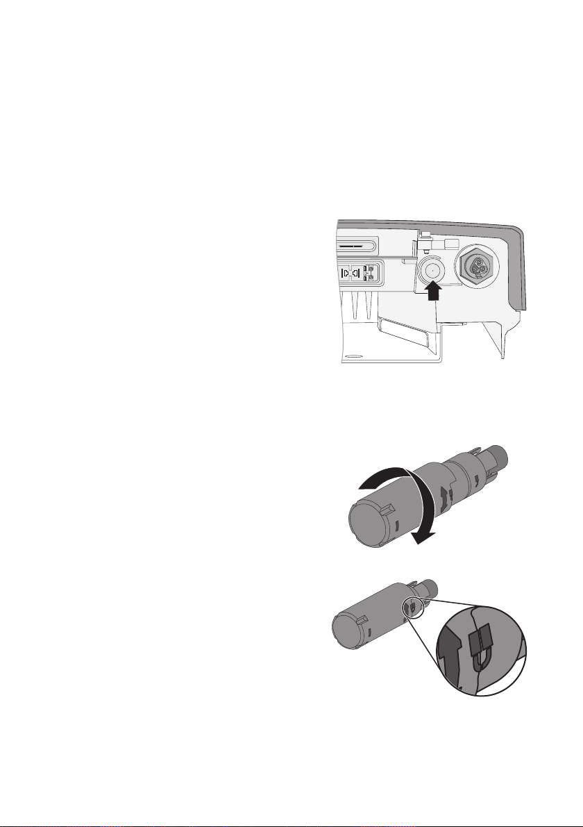
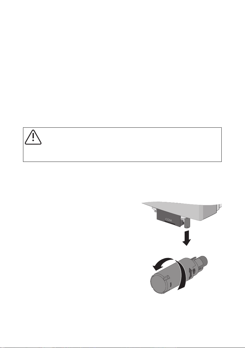
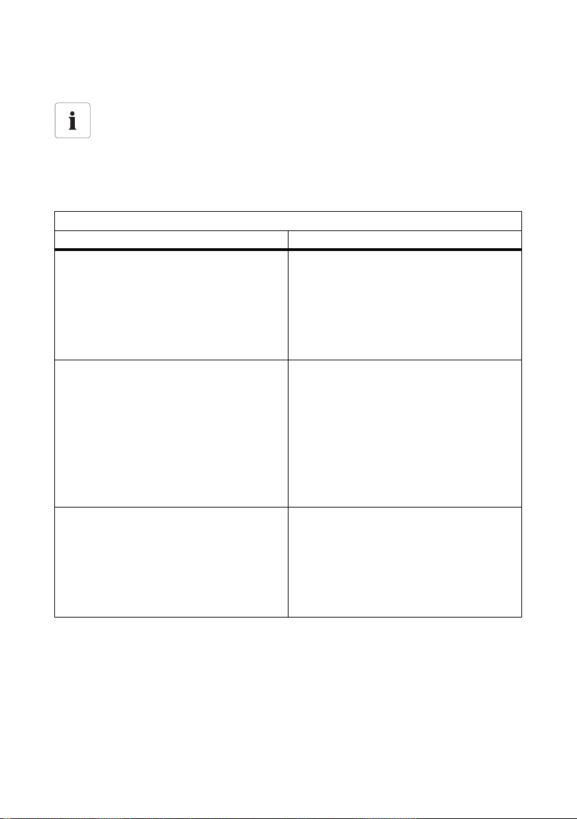
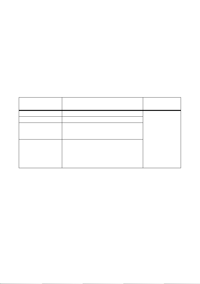
Anschlussbereich
Der Anschlussbereich des SMA Plug-in Grounding
befindet sich an der Unterseite des Wechselrichters.
Vorgehensweise
1. Den Wechselrichter AC- und DC-seitig freischalten,
wie in der Installationsanleitung des
Wechselrichters beschrieben.
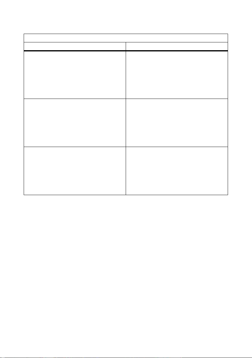
2. Prüfen, ob das SMA Plug-in Grounding fest
verschraubt ist: Anschlussteil festhalten und Kappe
handfest anziehen.
☑ Das SMA Plug‑in Grounding ist fest
verschlossen, wenn die Symbole auf dem
Anschlussteil und der Kappe ein Schloss bilden.
Installationsanleitung Erdung_HF-IXX105020 9
Page 10

SMA Plug-in Grounding installieren SMA Solar Technology AG
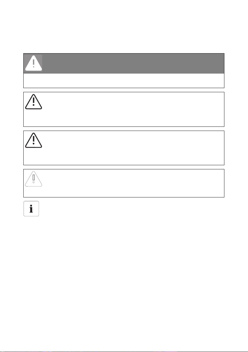
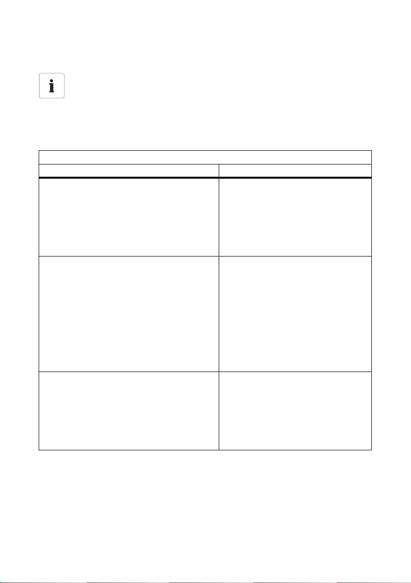
3. Schutzkappe vom Steckplatz am Wechselrichters
entfernen.
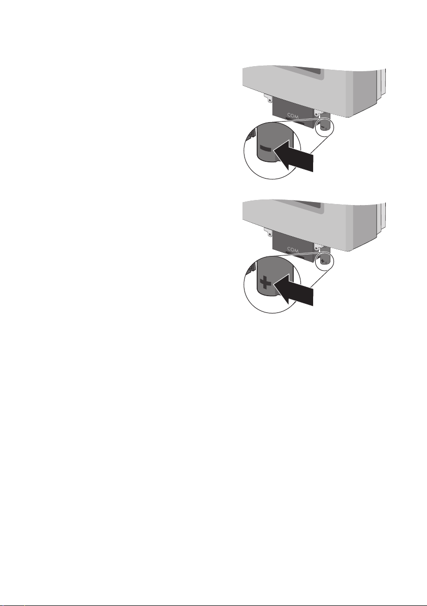
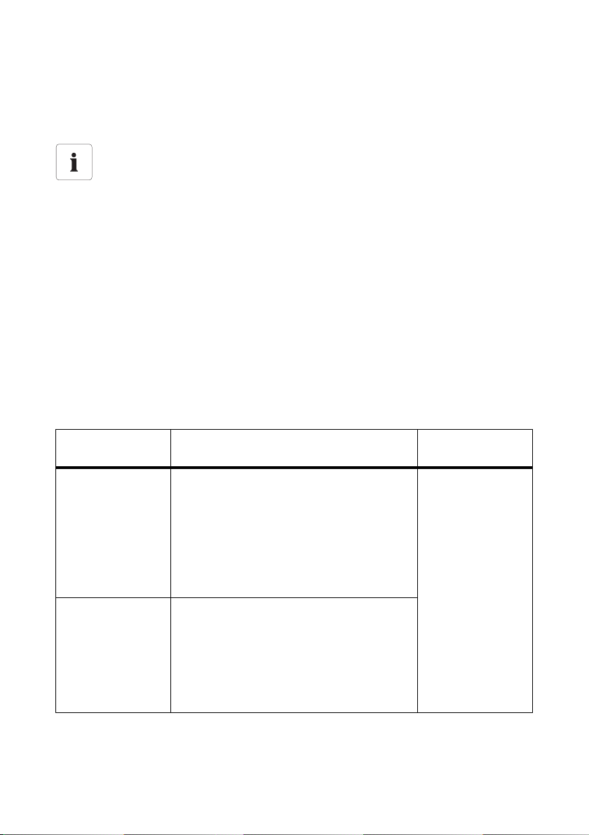
4. Wenn der negative Pol der PV-Anlage geerdet
sein soll:
– SMA Plug-in Grounding so an die
Anschlussbuchse setzen, dass das Symbol „ − “
auf der Kappe nach vorne zeigt.
– S MA P lug -in Gro und ing nach obe n dr ück en, bis
es einrastet.
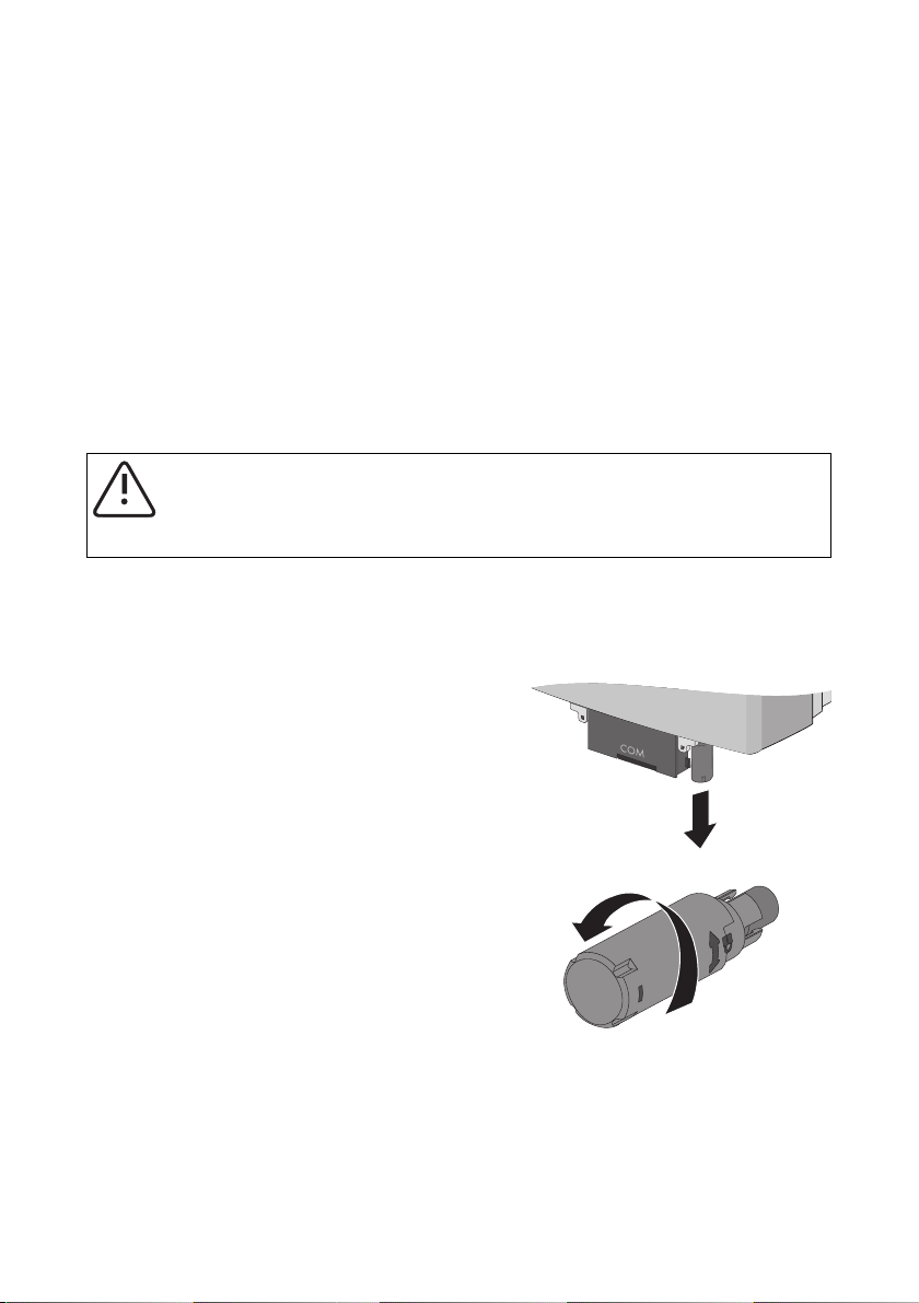
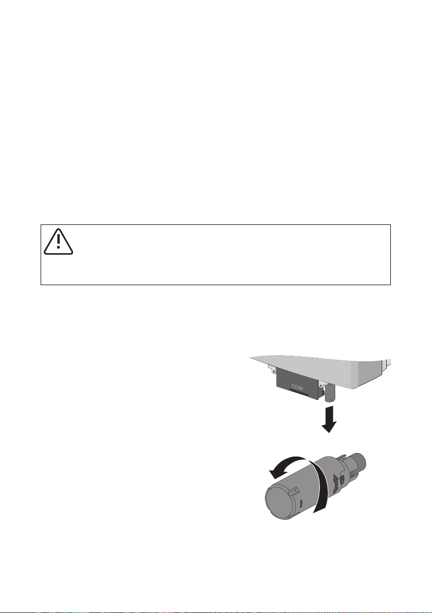
5. Wenn der positive Pol der PV-Anlage geerdet
sein soll:
– SMA Plug-in Grounding so an die
Anschlussbuchse setzen, dass das Symbol „+“
auf der Kappe nach vorne zeigt.
– S MA P lug -in Gro und ing nach obe n dr ück en, bis
es einrastet.
☑ Das SMA Plug-in Grounding ist installiert.
10 Erdung_HF-IXX105020 Installationsanleitung
Page 11
SMA Solar Technology AG Sicherung des SMA Plug-in Grounding prüfen und austauschen
5 Sicherung des SMA Plug-in Grounding prüfen und austauschen
Wenn ein Erdschluss in der PV-Anlage auftritt, reagiert das SMA Plug-in Grounding entsprechend der
Stärke des Fehlerstroms:
• Die Sicherung des SMA Plug-in Grounding unterbricht einen plötzlich auftretenden großen
Fehlerstrom. Dabei wird die Sicherung zerstört.
• Der Wechselrichter zeigt schleichend auftretende Fehlerströme an (siehe
Kapitel6.2„Fehlermeldungen“ (Seite16)). Wenn Sie den Erdschluss rechtzeitig beheben,
vermeiden Sie die Zerstörung der Sicherung.
Nachdem der Erdschluss behoben ist (siehe Installationsanleitung des Wechselrichters), müssen Sie
die Sicherung des SMA Plug-in Grounding prüfen und ggf. austauschen. Eine neue Sicherung erhalten
Sie bei SMA Solar Technology AG (Bestell-Nr. KLKD-1).
WARNUNG!
Brandgefahr durch ungeeignete Sicherungen!
• Nur Sicherungen des Typs Littelfuse KLKD-1 einsetzen, um den Schutz gegen
Brandgefahr beizubehalten.
Vorgehensweise
1. Den Wechselrichter AC- und DC-seitig freischalten, wie in der Installationsanleitung des
Wechselrichters beschrieben.
2. Vor Austausch der Sicherung Art der Generatorerdung („ − “ oder „+“) notieren.
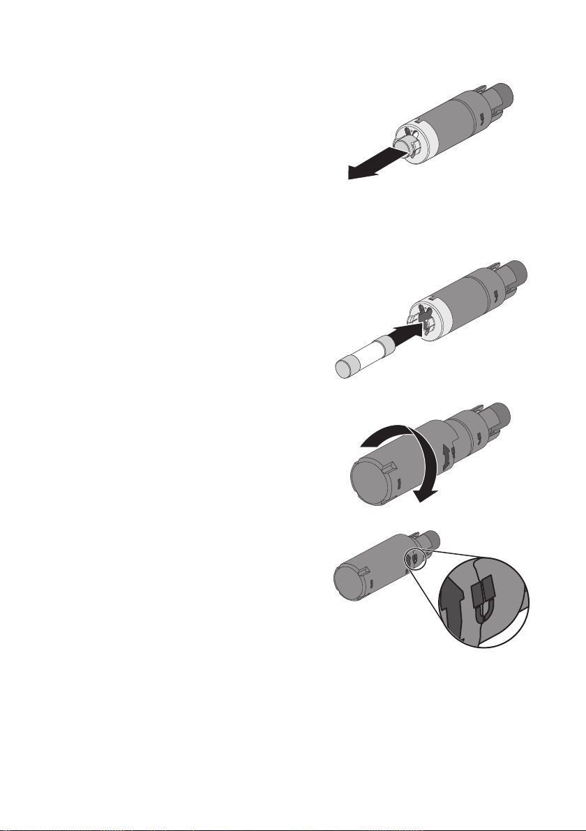
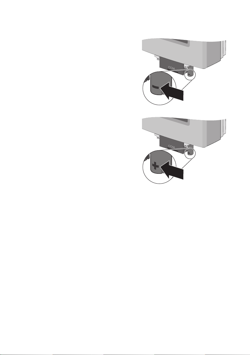
3. SMA Plug-in Grounding nach unten abziehen.
4. Das Anschlussteil des SMA Plug-in Grounding
festhalten und die Kappe lösen und abziehen.
Installationsanleitung Erdung_HF-IXX105020 11
Page 12
Sicherung des SMA Plug-in Grounding prüfen und austauschen SMA Solar Technology AG
5. Mit einer Zange die Sicherung aus dem
Sicherungshalter des SMA Plug-in Grounding
herausziehen.
6. Zustand der Sicherung mit geeignetem Messgerät
prüfen (Durchgangsprüfung).
☑ Wenn die Sicherung defekt ist, Sicherung
austauschen.
7. Funktionsfähige Sicherung in den Sicherungshalter
des SMA Plug-in Grounding einsetzen und fest in
den Sicherungshalter drücken.
8. Anschlussteil des SMA Plug-in Grounding
festhalten, Kappe aufsetzen und handfest
anziehen.
☑ Das SMA Plug‑in Grounding ist fest
verschlossen, wenn die Symbole auf dem
Anschlussteil und der Kappe ein Schloss bilden.
12 Erdung_HF-IXX105020 Installationsanleitung
Page 13

SMA Solar Technology AG Sicherung des SMA Plug-in Grounding prüfen und austauschen
9. Wenn der negative Pol der PV-Anlage geerdet
sein soll:
– SMA Plug-in Grounding so an die
Anschlussbuchse setzen, dass das Symbol „ − “
auf der Kappe nach vorne zeigt.
– S MA P lug -in Gro und ing nach obe n dr ück en, bis
es einrastet.
10. Wenn der positive Pol der PV-Anlage geerdet
sein soll:
– SMA Plug-in Grounding so an die
Anschlussbuchse setzen, dass das Symbol „+“
auf der Kappe nach vorne zeigt.
– S MA P lug -in Gro und ing nach obe n dr ück en, bis
es einrastet.
☑ Die Sicherung des SMA Plug-in Grounding ist ausgetauscht.
Installationsanleitung Erdung_HF-IXX105020 13
Page 14
Parameter und Fehlermeldungen SMA Solar Technology AG
6 Parameter und Fehlermeldungen
6.1 Einstellbare Parameter
Parameternamen abhängig von Kommunikationsart
Je nach Kommunikationsart (Bluetooth oder RS485) verwendet der Wechselrichter ein
anderes Kommunikationsprotokoll und die Parameter werden unterschiedlich dargestellt:
• Kommunikation über Bluetooth und Sunny Explorer: DATA II+
• Kommunikation über RS485: DATA I
Für die Erdung der PV-Anlage sind 2 Parameter wichtig, die Sie im Wechselrichter über ein
Kommunikationsgerät oder einen PC mit entsprechender Software einstellen können.
• Parameter „Modul-Erdung vorgeschrieben?“ (DATA II+) bzw. „Md.GndMdt“ (DATA I)
• Parameter „Vorgeschriebene Art der Erdung“ (DATA II+) bzw. „Md.GndModReq“ (DATA I)
6.1.1 Parameter „Modul-Erdung vorgeschrieben?“ bzw. „GndMdt“
Die Modul-Erdung ist im Wechselrichter über den Parameter „Modul-Erdung vorgeschrieben?“ bzw.
„Md.GndMdt“ einstellbar. Beachten Sie dabei die Vorgaben des Modulherstellers und die am
Installationsort der PV-Anlage geltenden Richtlinien.
Es gibt 2 Einstellmöglichkeiten:
Wert
(DATA II+ / DATA I)
Ne in / N o Ei ne Erdun g du rch nor mative V org aben ode r du rch
Ja / Yes Eine Erdung durch normative Vorgaben oder durch
14 Erdung_HF-IXX105020 Installationsanleitung
Erklärung Default-Wert
(DATA II+ / DATA I)
Nein / No
den Modulhersteller ist nicht vorgeschrieben.
Trotz dieser Einstellung können Sie die PV-Anlage
erden.
Bei einem Erdungsfehler speist der Wechselrichter
weiter ein. Der Wechselrichter gibt eine Warnung
mit der Ereignisnummer „35“ als Information aus.
den Modulhersteller ist zwingend
vorgeschrieben. Der Wechselrichter kann nur mit
SMA Plug-in Grounding betrieben werden.
Bei einem Erdungsfehler speist der Wechselrichter
nicht mehr ein und geht in die Betriebshemmung.
Der Wechselrichter zeigt einen Isolationsfehler mit
der Ereignisnummer „35“ an.
Page 15
SMA Solar Technology AG Parameter und Fehlermeldungen
6.1.2 Parameter „Vorgeschriebene Art der Erdung“ bzw. „Md.GndModReq“
Über den Parameter „Vorgeschriebene Art der Erdung“ bzw. „Md.GndModReq“ können Sie die
ge wün sch te E rdu ngs art fes tle gen . We rksseit ig i st d ies er P ara met er a uf „ Ler nen d“ b zw. „G ndM odL rn“
eingestellt.
Es gibt 2 Möglichkeiten, diesen Parameter festzulegen:
• Automatisch: Im Lernmodus speichert der Wechselrichter die Erdungsart des gesteckten
SMAPlug‑in Grounding automatisch nach 10Betriebsstunden.
• Manuell: Sie können die gewünschte Erdungsart über Kommunikation (Bluetooth/RS485)
ändern, nachdem Sie den Wechselrichter in Betrieb genommen haben. Die manuelle
Einstellung des Parameters ist auch ohne SMA Plug-in Grounding möglich.
Es gibt 4 Einstellmöglichkeiten:
Wert
(DATA II+ / DATA I)
Positiv / GndModPs Der Wechselrichter erlaubt nur eine positive
Negativ / GndModNg Der Wechselrichter erlaubt nur eine negative
Keine vorgeschrieben /
GndModNoneReq
Lernend / GndModLrn Der Wechselrichter überwacht die Erdung und
Erklärung Default-Wert
Erdung.
Erdung.
Es ist keine bestim mte Erdungs art vorgesc hrieben .
Der Wechselrichter kann mit oder ohne Erdung
betrieben werden.
speichert nach 10 Betriebsstunden mit
gestecktem SMA Plug-in Grounding die
Erdungsart.
Der Wechselrichter kann mit oder ohne Erdung
betrieben werden.
(DATA II+ / DATAI)
Lernend /
GndModLrn
Installationsanleitung Erdung_HF-IXX105020 15
Page 16
Parameter und Fehlermeldungen SMA Solar Technology AG
6.2 Fehlermeldungen
Fehler immer beheben
Beheben Sie auftretende Fehler umgehend, auch wenn der Wechselrichter weiter einspeist.
Ab hän gig von der Ein ste llu ng d es P ara met ers „Mo dul- Erd ung vor geschrieben?“ bzw. „Md.GndMdt“
verhält sich der Wechselrichter unterschiedlich.
Folgende Fehlermeldungen können auftreten:
Parameter „Modul-Erdung vorgeschrieben?“/ „Md.GndMdt“
Einstellung: Ja / Yes Ursache / Abhilfe
• Ereignisnummer 35
• Display-Meldung <Stoerung
Erdungssicherung - Erdungssich. pruefen>
•Rote LED leuchtet dauerhaft.
• Grüne LED blinkt oder erlischt.
• Wechselrichter speist nicht ein.
• Ereignisnummer 35
• Display-Meldung
<Iso.-Widerstand - Generator pruefen>
•Rote LED leuchtet dauerhaft.
• Grüne LED blinkt oder erlischt.
• Wechselrichter speist nicht ein.
• Ereignisnummer 42
• Display-Meldung
<Erdungsart falsch, Erdungsset pruefen>
•Rote LED leuchtet dauerhaft.
• Grüne LED blinkt oder erlischt.
• Wechselrichter speist nicht ein.
Ein Überstrom ist aufgetreten.
• Den Fehler beheben, wie in
Kapitel6.3.2„Störung der
Erdungssicherung beheben“ (Seite18)
beschrieben.
Ein Isolationsfehler liegt vor.
• Wenn ein SMA Plug-in Grounding installiert
ist, den Fehler beheben, wie in
Kapitel6.3.3„Isolationsfehler beheben“
(Seite19) beschrieben.
• Wenn das SMA Plug-in Grounding fehlt,
SMAPlug-in Grounding anschließen wie in
Kapitel 4„SMA Plug-in Grounding
installieren“ (Seite9) beschrieben.
Das SMA Plug-in Grounding ist verpolt
angeschlossen oder fehlt.
• Den Fehler beheben, wie in Kapitel
6.3.4„Erdungsart korrigieren“ (Seite19)
beschrieben.
16 Erdung_HF-IXX105020 Installationsanleitung
Page 17
SMA Solar Technology AG Parameter und Fehlermeldungen
Parameter „Modul-Erdung vorgeschrieben?“/ „Md.GndMdt“
Einstellung: Nein / No Ursache / Abhilfe
• Ereignisnummer 35
• Display-Meldung
<Iso.-Widerstand - Generator pruefen>
•Rote LED leuchtet dauerhaft.
• Grüne LED leuchtet dauerhaft.
• Wechselrichter speist ein.
• Ereignisnummer 35
• Display-Meldung
<Iso.-Widerstand - Generator pruefen>
•Rote LED leuchtet dauerhaft.
• Grüne LED leuchtet dauerhaft.
• Wechselrichter speist ein.
• Ereignisnummer 42
• Display-Meldung
<Erdungsart falsch, Erdungsset pruefen>
•Rote LED leuchtet dauerhaft.
• Grüne LED leuchtet dauerhaft.
• Wechselrichter speist ein.
Ein Überstrom ist aufgetreten.
• Den Fehler beheben, wie in Kapitel
6.3.3„Isolationsfehler beheben“
(Seite19) beschrieben.
Ein Isolationsfehler liegt vor.
• Fehler beheben, wie in Kapitel
6.3.3„Isolationsfehler beheben“
(Seite19) beschrieben.
Das SMA Plug-in Grounding ist verpolt
angeschlossen oder fehlt.
• Fehler beheben, wie in Kapitel
6.3.4„Erdungsart korrigieren“ (Seite19)
beschrieben.
Installationsanleitung Erdung_HF-IXX105020 17
Page 18

Parameter und Fehlermeldungen SMA Solar Technology AG
6.3 Fehler beheben
6.3.1 Sicherheit
GEFAHR!
Lebensgefahr durch Stromschlag!
Der Wechselrichter arbeitet mit hohen Spannungen.
• Den Wechselrichter AC- und DC-seitig freischalten, wie in der Installationsanleitung
des Wechselrichters beschrieben.
6.3.2 Störung der Erdungssicherung beheben
Gehen Sie wie folgt vor, um den Fehler <Stoerung Erdungssicherung - Erdungssich. pruefen> zu
beheben:
1. Den Wechselrichter AC- und DC-seitig freischalten, wie in der Installationsanleitung des
Wechselrichters beschrieben.
2. Art der Generatorerdung („ − “ oder „+“) notieren und SMA Plug-in Grounding nach unten
abziehen.
3. PV-Generator auf Erdschluss prüfen, wie in der Installationsanleitung des Wechselrichters
beschrieben und ggf. Erdschluss beseitigen.
4. Den Wechselrichter ohne SMA Plug-in Grounding wieder in Betrieb nehmen, wie in der
Installationsanleitung des Wechselrichters beschrieben.
☑ Der Wechselrichter prüft, ob der Erdschluss noch vorliegt.
–Liegt kein Erdschluss mehr vor, dann ändert sich die Fehlermeldung <Stoerung
Erdungssicherung> in <Iso.-Widerstand>, sobald die Startspannung 220V beträgt.
– Liegt weiterhin ein Erdschluss vor, dann bleibt die Fehlermeldung <Stoerung
Erdungssicherung> bestehen. In diesem Fall Schritt 3 und 4 wiederholen.
5. Den Wechselrichter AC- und DC-seitig freischalten, wie in der Installationsanleitung des
Wechselrichters beschrieben.
6. Sicherung des SMA Plug-in Grounding prüfen und ggf. austauschen, wie in
Kapitel5„Sicherung des SMA Plug-in Grounding prüfen und austauschen“ (Seite11)
beschrieben.
7. Funktionsfähiges SMA Plug-in Grounding an den Wechselrichter anschließen, wie in
Kapitel4„SMA Plug-in Grounding installieren“ (Seite9) beschrieben.
8. Den Wechselrichter wieder in Betrieb nehmen, wie in der Installationsanleitung des
We chs elr ich ter s be sch rie ben . Da bei prü ft d er W ech selr ich ter , ob die ein ges tel lte Erdu ngs art mit
der Erdungsart des installierten SMA Plug-in Grounding übereinstimmt.
☑ Nach der Wiederinbetriebnahme speist der Wechselrichter wieder ein.
18 Erdung_HF-IXX105020 Installationsanleitung
Page 19

SMA Solar Technology AG Parameter und Fehlermeldungen
6.3.3 Isolationsfehler beheben
Gehen Sie wie folgt vor, um den Fehler <Iso.-Widerstand - Generator pruefen> zu beheben:
1. Den Wechselrichter AC- und DC-seitig freischalten, wie in der Installationsanleitung des
Wechselrichters beschrieben.
2. Wenn ein SMA Plug-in Grounding angeschlossen ist, Art der Generatorerdung („ − “ oder „+“)
notieren und SMA Plug-in Grounding nach unten abziehen.
3. PV-Generator auf Erdschluss prüfen, wie in der Installationsanleitung des Wechselrichters
beschrieben und ggf. Erdschluss beseitigen.
4. Sicherung des SMA Plug-in Grounding prüfen und ggf. austauschen, wie in
Kapitel5„Sicherung des SMA Plug-in Grounding prüfen und austauschen“ (Seite11)
beschrieben.
5. Funktionsfähiges SMA Plug-in Grounding an den Wechselrichter anschließen, wie in
Kapitel4„SMA Plug-in Grounding installieren“ (Seite9) beschrieben.
6. Den Wechselrichter wieder in Betrieb nehmen, wie in der Installationsanleitung des
Wechselrichters beschrieben.
☑ Der Wechselrichter prüft, ob der Erdschluss noch vorliegt und ob die eingestellte Erdungsart
mit der Erdungsart des installierten SMA Plug-in Grounding übereinstimmt.
– Wenn der Erdschluss weiterhin vorliegt, bleibt die Fehlermeldung <Iso.-Widerstand -
Generator pruefen> bestehen. In diesem Fall Schritt 3 bis 6 wiederholen.
– Wenn kein Erdschluss mehr vorliegt, erlischt die Fehlermeldung <Iso.-Widerstand-
Generator pruefen> und der Wechselrichter speist wieder ein.
– Falls eine positive oder negative Erdung vorgeschrieben ist und das SMA Plug-in
Grounding mit falscher Polung angeschlossen wurde, erscheint die Fehlermeldung
<Erdungsart falsch, Erdungsset pruefen>. Mit Kapitel 6.3.4„Erdungsart korrigieren“
(Seite19) fortfahren.
☑ Nach der Wiederinbetriebnahme speist der Wechselrichter wieder ein.
6.3.4 Erdungsart korrigieren
Gehen Sie wie folgt vor, um den Fehler <Erdungsart falsch, Erdungsset pruefen> zu beheben:
1. Den Wechselrichter AC- und DC-seitig freischalten, wie in der Installationsanleitung des
Wechselrichters beschrieben.
2. Funktionsfähiges SMA Plug-in Grounding mit korrekter Polung an den Wechselrichter
anschließen, wie in Kapitel 4„SMA Plug-in Grounding installieren“ (Seite9) beschrieben.
3. Den Wechselrichter wieder in Betrieb nehmen, wie in der Installationsanleitung des
Wechselrichters beschrieben. Dabei prüft der Wechselrichter, ob die Erdungsart mit der
eingestellten bzw. erlernten Erdungsart übereinstimmt.
☑ Der Fehler ist behoben und der Wechselrichter speist wieder ein.
Installationsanleitung Erdung_HF-IXX105020 19
Page 20

Kontakt SMA Solar Technology AG
7 Kontakt
Bei technischen Problemen mit unseren Produkten wenden Sie sich an die SMA Serviceline. Wir
benötigen die folgenden Daten, um Ihnen gezielt helfen zu können:
• Wechselrichtertyp
• Seriennummer des Wechselrichters
• Angeschlossene PV-Module und Anzahl der PV-Module
• Art der Erdung (positiv oder negativ)
• Ereignisnummer oder Display-Meldung des Wechselrichters
• optionale Ausstattung (z. B. Kommunikationsgeräte)
• gegebenenfalls Art des angeschlossenen Multifunktionsrelais
SMA Solar Technology AG
Sonnenallee 1
34266 Niestetal
www.SMA.de
SMA Serviceline
Wechselrichter: +49 561 9522 1499
Kommunikation: +49 561 9522 2499
SMS mit „RÜCKRUF“ an: +49 176 888 222 44
Fax: +49 561 9522 4699
E-Mail: Serviceline@SMA.de
20 Erdung_HF-IXX105020 Installationsanleitung
Page 21

SMA Solar Technology AG Rechtliche Bestimmungen
Die in diesen Unterlagen enthaltenen Informationen sind Eigentum der SMA Solar Technology AG. Die Veröffentlichung, ganz
oder in Teilen, bedarf der schriftlichen Zustimmung der SMA Solar Technology AG. Eine innerbetriebliche Vervielfältigung, die zur
Evaluierung des Produktes oder zum sachgemäßen Einsatz bestimmt ist, ist erlaubt und nicht genehmigungspflichtig.
Haftungsausschluss
Es gelten als Grundsatz die Allgemeinen Lieferbedingungen der SMA Solar Technology AG.
Der Inhalt dieser Unterlagen wird fortlaufend überprüft und gegebenenfalls angepasst. Trotzdem können Abweichungen nicht
ausgeschlossen werden. Es wird keine Gewähr für Vollständigkeit gegeben. Die jeweils aktuelle Version ist im Internet unter
www.SMA.de abrufbar oder über die üblichen Vertriebswege zu beziehen.
Gewährleistungs- und Haftungsansprüche bei Schäden jeglicher Art sind ausgeschlossen, wenn sie auf eine oder mehrere der
folgenden Ursachen zurückzuführen sind:
• Transportschäden
• Unsachgemäße oder nicht bestimmungsgemäße Verwendung des Produkts
• Betreiben des Produkts in einer nicht vorgesehenen Umgebung
• Betreiben des Produkts unter Nichtberücksichtigung der am Einsatzort relevanten gesetzlichen Sicherheitsvorschriften
• Nichtbeachten der Warn- und Sicherheitshinweise in allen für das Produkt relevanten Unterlagen
• Betreiben des Produkts unter fehlerhaften Sicherheits- und Schutzbedingungen
• Eigenmächtiges Verändern oder Reparieren des Produkts oder der mitgelieferten Software
• Fehlverhalten des Produkts durch Einwirkung angeschlossener oder benachbarter Geräte außerhalb der gesetzlich zulässigen
Grenzwerte
• Katastrophenfälle und höhere Gewalt
Die Nutzung der mitgelieferten von der SMA Solar Technology AG hergestellten Software unterliegt zusätzlich den folgenden
Bedingungen:
• Die SMA Solar Technology AG lehnt jegliche Haftung für direkte oder indirekte Folgeschäden, die sich aus der Verwendung
der von SMA Solar Technology AG erstellten Software ergeben, ab. Dies gilt auch für die Leistung beziehungsweise NichtLeistung von Support-Tätigkeiten.
• Mitgelieferte Software, die nicht von der SMA Solar Technology AG erstellt wurde, unterliegt den jeweiligen Lizenz- und
Haftungsvereinbarungen des Herstellers.
SMA Werksgarantie
Die aktuellen Garantiebedingungen liegen Ihrem Gerät bei. Bei Bedarf können Sie diese auch im Internet unter www.SMA.de
herunterladen oder über die üblichen Vertriebswege in Papierform beziehen.
Warenzeichen
Alle Warenzeichen werden anerkannt, auch wenn diese nicht gesondert gekennzeichnet sind. Fehlende Kennzeichnung bedeutet
nicht, eine Ware oder ein Zeichen seien frei.
Die Bluetooth
Marken durch die SMA Solar Technology AG erfolgt unter Lizenz.
SMA Solar Technology AG
Sonnenallee 1
34266 Niestetal
Deutschland
Tel. +49 561 9522-0
Fax +49 561 9522-100
www.SMA.de
E-Mail: info@SMA.de
© 2004 bis 2010 SMA Solar Technology AG. Alle Rechte vorbehalten.
®
Wortmarke und Logos sind eingetragene Warenzeichen der Bluetooth SIG, Inc. und jegliche Verwendung dieser
Installationsanleitung Erdung_HF-IXX105020 21
Page 22

Table of Contents SMA Solar Technology AG
Table of Contents
1 Notes on this Guide . . . . . . . . . . . . . . . . . . . . . . . . . . . . . . 23
1.1 Validity . . . . . . . . . . . . . . . . . . . . . . . . . . . . . . . . . . . . . . . . . . . 23
1.2 Target Group . . . . . . . . . . . . . . . . . . . . . . . . . . . . . . . . . . . . . . 23
1.3 Additional Information . . . . . . . . . . . . . . . . . . . . . . . . . . . . . . . 23
1.4 Symbols Used. . . . . . . . . . . . . . . . . . . . . . . . . . . . . . . . . . . . . . 24
2 Safety . . . . . . . . . . . . . . . . . . . . . . . . . . . . . . . . . . . . . . . . . 25
2.1 Appropriate Usage. . . . . . . . . . . . . . . . . . . . . . . . . . . . . . . . . . 25
2.2 Safety Precautions. . . . . . . . . . . . . . . . . . . . . . . . . . . . . . . . . . . 26
3 Scope of Delivery. . . . . . . . . . . . . . . . . . . . . . . . . . . . . . . . 27
4 Installing the SMA Plug-in Grounding . . . . . . . . . . . . . . . 28
5 Inspecting and Replacing the fuse of the SMA
Plug-in Grounding . . . . . . . . . . . . . . . . . . . . . . . . . . . . . . . 30
6 Parameters and Error Messages . . . . . . . . . . . . . . . . . . . 33
6.1 Configurable Parameters . . . . . . . . . . . . . . . . . . . . . . . . . . . . . 33
6.1.1 Parameter "Module grounding prescribed?" or "GndMdt". . . . . . . . . . . . . . 33
6.1.2 Parameter "Prescribed grounding type" or "Md.GndModReq" . . . . . . . . . . 34
6.2 Error Messages. . . . . . . . . . . . . . . . . . . . . . . . . . . . . . . . . . . . . 35
6.3 Correct Error . . . . . . . . . . . . . . . . . . . . . . . . . . . . . . . . . . . . . . . 37
6.3.1 Safety . . . . . . . . . . . . . . . . . . . . . . . . . . . . . . . . . . . . . . . . . . . . . . . . . . . . . . 37
6.3.2 Correct Gorund Fuse Fault . . . . . . . . . . . . . . . . . . . . . . . . . . . . . . . . . . . . . . 37
6.3.3 Correct Insulation Error . . . . . . . . . . . . . . . . . . . . . . . . . . . . . . . . . . . . . . . . . 38
6.3.4 Correct the Grounding Type . . . . . . . . . . . . . . . . . . . . . . . . . . . . . . . . . . . . . 38
7 Contact . . . . . . . . . . . . . . . . . . . . . . . . . . . . . . . . . . . . . . . . 39
22 Erdung_HF-IXX105020 Installation Guide
Page 23

SMA Solar Technology AG Notes on this Guide
1 Notes on this Guide
1.1 Validity
Th is g uid e de scr ibes the con nec tio n of the gro und ing set S MA P lug-in Grounding and the replacement
of fuses in the SMA Plug-in Grounding.
The SMA Plug-in Grounding may only be used with the following SMA inverters:
• Sunny Boy 2000HF (SB 2000HF-30),
• Sunny Boy 2500HF (SB 2500HF-30),
• Sunny Boy 3000HF (SB 3000HF-30).
Keep this guide in a convenient place for future reference.
1.2 Target Group
This guide is meant for qualified electricians. The tasks described in this guide may be performed by
qualified electricians only.
1.3 Additional Information
Detailed information regarding installation, commissioning, maintenance and troubleshooting of the
inverter can be found in the respective installation guide.
Installation Guide Erdung_HF-IXX105020 23
Page 24
Notes on this Guide SMA Solar Technology AG
1.4 Symbols Used
The following types of safety precautions and general information are used in this guide:
DANGER!
G
DANGER indicates a hazardous situation which, if not avoided, will result in death or
serious injury.
WARNING!
WARNING indicates a hazardous situation which, if not avoided, could result in death or
serious injury.
CAUTION!
CAUTION indicates a hazardous situation which, if not avoided, could result in minor or
moderate injury.
NOTICE!
NOTICE indicates a situation that can result in property damage if not avoided.
Information
Information provides tips that are valuable for the optimal installation and operation of
your product.
☑ This symbol indicates the result of an action.
24 Erdung_HF-IXX105020 Installation Guide
Page 25

SMA Solar Technology AG Safety
2 Safety
2.1 Appropriate Usage
If you use spe cif ic solar cel l techno log y ty pes in y our PV generator, e.g. thin film or backside contacted
PV modules, it may become necessary to ground either the positive or the negative terminal of the PV
plant. The SMA Plug-in Grounding facilitates the grounding of the PV generator in the inverter. The
'plug-in' grounding set is suitable for inverters of the types SB 2000HF-30, SB 2500HF-30 and
SB3000HF-30. With the help of this device-internal grounding, a safe operation is achieved over the
long-term with optimal EMC characteristics and minimal installation costs.
The SMA Plug-in Grounding set includes a 1A fuse as a protection against fire hazard and a circuit
that adjusts the inverter's insulation monitoring to the SMA Plug-in Grounding. Via the fuse, the SMA
Plug-in Grounding establishes a direct connection between the terminal to be grounded (positive or
negative) and the PV module and the PE terminal of the inverter. If a ground fault occurs, the fuse in
the SMA Plug-in Grounding disconnects the residual current.
Information about type and requirements for a module grounding of your PV plant will be provided
by your module manufacturer.
The inverter may only be operated with PV generators (modules and cabling) that contain protective
insulation (protection class II).
The SMA Plug-in Grounding is only suitable for use with SMA inverters of the types
SunnyBoy2000HF/2500HF/3000HF.
Installation Guide Erdung_HF-IXX105020 25
Page 26

Safety SMA Solar Technology AG
2.2 Safety Precautions
DANGER!
Danger to life due to high voltages in the inverter.
• All work on the inverter and the connection of the SMA Plug-in Grounding may be
carried out only by a qualified electrician.
DANGER!
Electric shock caused by high voltage in the inverter!
• Disconnect the inverter from both the AC and DC sides before you connect the
SMAPlug-in Grounding, as described in the inverter's installation guide.
NOTICE!
A faulty connection may damage the SMA Plug-in Grounding or the inverter!
A faulty connection of the SMA Plug-in Grounding set can lead to short circuits and can
cause irreparable damage to the SMA Plug-in Grounding and the inverter. All warranty
claims become void.
• Connect the SMA Plug-in Grounding as described in the following sections.
Connection of conductive parts in the substructure of the PV generator with the
grounding system
Certain module manufacturers demand the grounding of a generator terminal in order to
avoid potential differences between the ground potential of the grounding set and the
surrounding of the PV generator. By grounding the substructure of the PV generator these
differences in potential will be avoided. Additionally this potential equalization provides
the best possible protection via the fuse integrated in the grounding set.
26 Erdung_HF-IXX105020 Installation Guide
Page 27

SMA Solar Technology AG Scope of Delivery
3 Scope of Delivery
Check the delivery for completeness and any visible external damage. Contact your dealer if anything
is damaged or missing.
Object Number Description
A 1 SMA Plug-in Grounding
B 1 Installation Guide
Installation Guide Erdung_HF-IXX105020 27
Page 28
Installing the SMA Plug-in Grounding SMA Solar Technology AG
4 Installing the SMA Plug-in Grounding
If a ground fault occurs in the PV plant, the fuse in the SMA Plug-in Grounding interrupts the residual
current.
The positive or negative grounding of the inverter is coded in the SMA Plug-in Grounding. You must
only start up the inverter, if the SMA Plug-in Grounding is installed according to the grounding of your
PV plant.
Connection area
The connection area in the SMA Plug-in Grounding can
be found at the underside of the inverter.
Procedure
1. Disconnect the inverter on the AC and DC sides as described in the inverter's installation guide.
2. Check whether the SMA Plug-in Grounding has been tightened properly:
Hold the connecting part of the SMA Plug-in Grounding tightly and tighten the cap by hand.
☑ T he S MA P lug -in Gro und ing has bee n ti ght ene d
properly, if the symbols on the connecting part
and the cap together form a lock.
3. Remove the p rotective cap f rom the plug-in position
on the inverter.
28 Erdung_HF-IXX105020 Installation Guide
Page 29
SMA Solar Technology AG Installing the SMA Plug-in Grounding
4. If the negative terminal of the PV plant is to be
grounded:
– Connect the SMA Plug-in Grounding to the
terminal socket in such a way that the symbol
" − " of the cap is at the front of the cap.
– Push the SMA Plug-in Grounding upwards until
it clicks into place.
5. If the positive terminal of the PV plant is to be
grounded:
– Connect the SMA Plug-in Grounding to the
terminal socket in such a way that the symbol
"+" of the cap is at the front of the cap.
– Push the SMA Plug-in Grounding upwards until
it clicks into place.
☑ The SMA Plug-in Grounding is installed.
Installation Guide Erdung_HF-IXX105020 29
Page 30
Inspecting and Replacing the fuse of the SMA Plug-in Grounding SMA Solar Technology AG
5 Inspecting and Replacing the fuse of the SMA Plug-in Grounding
If a ground fault in the PV plant occurs, the SMA Plug-in Grounding reacts in accordance with the
residual current:
• The fuse of the SMA Plug-in Grounding interrupts a suddenly occurring intense esidual current.
This action destroys the fuse.
• The inverter detects lingering residual currents (see section 6.2”Error Messages” (page35)).
If you eliminate the ground fault in time, you can avoid the destruction of the fuse.
After having eliminated the ground fault (see the inverter's installation guide), you will need to inspect
the fuse of the SMA Plug-in Grounding and replace it if necessary. You can order a new fuse from
SMASolar Technology AG (Order No. KLKD-1).
WARNING!
Fire hazard caused by the use of inappropriate fuses!
• Only use fuses of the type Littelfuse KLKD-1 to avoid fire hazards.
Procedure
1. Disconnect the inverter on the AC and DC sides as described in the inverter's installation guide.
2. Before you replace the fuse, make a note of the generator's grounding type (" − " or "+").
3. Remove the SMA Plug-in Grounding by pulling it
downwards.
4. Hold the connecting part of the SMA Plug-in
Grounding tightly, loosen the cap and pull it off.
30 Erdung_HF-IXX105020 Installation Guide
Page 31

SMA Solar Technology AG Inspecting and Replacing the fuse of the SMA Plug-in Grounding
5. Using pliers pull the fuse out from the fuse holder of
the SMA Plug-in Grounding.
6. Check the status of the fuse with an appropriate
measuring device (continuity test).
☑ If the fuse appears to be faulty, replace the fuse.
7. Insert a working fuse into the fuse holder of the
SMA Plug-in Grounding and push firmly into the
fuse holder.
8. Hold the connecting part of the SMA Plug-in
Grounding tightly, replace the cap of the SMA
Plug-in Grounding and tighten by hand.
☑ T he S MA P lug -in Gro und ing has bee n ti ght ene d
properly, if the symbols on the connecting part
and the cap together form a lock.
Installation Guide Erdung_HF-IXX105020 31
Page 32
Inspecting and Replacing the fuse of the SMA Plug-in Grounding SMA Solar Technology AG
9. If the negative terminal of the PV plant is to be
grounded:
– Connect the SMA Plug-in Grounding to the
terminal socket in such a way that the symbol
" − " of the cap is at the front of the cap.
– Push SMA Plug-in Grounding upwards until it
clicks into place.
10. If the positive terminal of the PV plant is to be
grounded:
– Connect the SMA Plug-in Grounding to the
terminal socket in such a way that the symbol
"+" of the cap is at the front of the cap.
– Push the SMA Plug-in Grounding upwards until
it clicks into place.
☑ The fuse of the SMA Plug-in Grounding has been replaced.
32 Erdung_HF-IXX105020 Installation Guide
Page 33
SMA Solar Technology AG Parameters and Error Messages
6 Parameters and Error Messages
6.1 Configurable Parameters
Parameter names according to the type of communication
Depending on the communication type (Bluetooth or RS485), the inverter uses a different
communication protocol and the parameters are displayed differently.
• Communication via Bluetooth and Sunny Explorer: DATA II+
• Communication via RS485: DATA I
Two parameters are important for the grounding of the PV plant. You can configure these parameters
in the inverter via a communication device or a PC with the appropriate software.
• Parameter "Module grounding prescribed?" (DATA II+) or "Md.GndMdt" (DATA I)
• Parameter "Prescribed grounding type" (DATA II+) or "Md.GndModReq" (DATA I)
6.1.1 Parameter "Module grounding prescribed?" or "GndMdt"
The grounding module in the inverter is configured via the parameter "Module grounding
prescribed?" or "Md.GndMdt". Make sure you comply with the requirements of the module
manufacturer as well as the regulations applicable at the installation location of the PV plant.
There are two configuration possibilities:
Value
(DATA II+ / DATA I)
No The grounding is not prescribed by normative
Yes Grounding is prescribed by normative regulation
Installation Guide Erdung_HF-IXX105020 33
Explanation Default Value
(DATA II+ / DATA I)
No
regulation or the manufacturer. Despite this
configuration, you will be able to ground the PV
plant.
In case of a grounding error, the inverter will
continue to feed into the grid. For information
purposes, the inverter displays a warning with the
event number "35".
or the module manufacturer. The inverter can only
be operated with an SMA Plug-in Grounding set.
In case of a grounding error, the inverter will not
continue to feed into the grid and interrupts
operation. The inverter displays a warning with the
event number "35" in case of an insulation error.
Page 34
Parameters and Error Messages SMA Solar Technology AG
6.1.2 Parameter "Prescribed grounding type" or "Md.GndModReq"
Via the parameter "Prescribed grounding type" or "Md.GndModReq" you will be able to specify the
required grounding type. Default configuration for the parameter is "Learning" or "GndModLrn".
There are two ways to specify this parameter:
• Automatically: When in learning mode, the inverter automatically saves the grounding type
of the plugged in SMA Plug-in Grounding after 10 hours of operation.
• Manually: You can change the grounding type you want to use via the communication tool
(Bluetooth/RS485), after you have started up the inverter. It is also possible to manually
configure the parameter without the SMA Plug-in Grounding.
There are four configuration options:
Value
(DATA II+ / DATA I)
Positive / GndModPs The inverter only allows positive grounding. Learning /
Negative / GndModNg The inverter only allows negative grounding.
None prescribed /
GndModNoneReq
Learning / GndModLrn The inverter detects the grounding and, after 10
Explanation Default Value
(DATA II+ / DATA I)
GndModLrn
No specific grounding mode is required. The
inverter can be operated with or without
grounding.
hours of operation with the plugged in SMA
Plug‑in Grounding, saves the grounding type.
The inverter can be operated with or without
grounding.
34 Erdung_HF-IXX105020 Installation Guide
Page 35
SMA Solar Technology AG Parameters and Error Messages
6.2 Error Messages
Always correct errors
Immediately correct errors, even if the inverter continues to feed into the grid.
The inverter behaves differently, depending on the configuration o f th e parame ter "Mo dul e gr ounding
prescribed?" or "MdGndMdt".
The following error messages may occur:
Parameter "Module grounding prescribed?" / "MdGndMdt"
Configuration: Yes Cause / Correction
• Event number 35
• Display message
< Ground fuse fault - check ground fuse >
• Red LED glows continuously.
• Green LED blinks or disappears.
• The inverter does not feed into the grid.
• Event number 35
• Display message
< Insulation resist. - check generator >
• Red LED glows continuously.
• Green LED blinks or disappears.
• The inverter does not feed into the grid.
• Event number 42
• Display message
< Wrong earthing type; check earthing set >
• Red LED glows continuously.
• Green LED blinks or disappears.
• The inverter does not feed into the grid.
An overcurrent has occurred.
• Correct the error as described in
section 6.3.2”Correct Gorund Fuse
Fault” (page37).
An insulation fault has occurred.
• If an SMA Plug-in Grounding is
installed, correct the fault as described
in section 6.3.3”Correct Insulation
Error” (page38).
• If the SMA Plug-in Grounding is
missing, connect the SMA Plug-in
Grounding as described in
section4”Installing the SMA Plug-in
Grounding” (page28)
The SMA Plug-in Grounding has been
connected incorrectly (reverse polarity) or is
missing.
• Correct the error as described in
section 6.3.4”Correct the Grounding
Type” (page38).
Installation Guide Erdung_HF-IXX105020 35
Page 36

Parameters and Error Messages SMA Solar Technology AG
Parameter "Module grounding prescribed?" / "MdGndMdt"
Configuration: No Cause Correction
• Event number 35
• Display message
< Insulation resist. - check generator >
• Red LED glows continuously.
• Green LED glows continuously.
• The inverter feeds into the grid.
• Event number 35
• Display message
< Insulation resist. - check generator >
• Red LED glows continuously.
• Green LED glows continuously.
• The inverter feeds into the grid.
• Event number 42
• Display message
< Wrong earthing type; check earthing set >
• Red LED glows continuously.
• Green LED glows continuously.
• The inverter feeds into the grid.
An overcurrent has occurred.
• Correct the error as described in
section .6.3.3”Correct Insulation
Error” (page38).
An insulation fault has occurred.
• Correct the error as described in
section 6.3.3”Correct Insulation Error”
(page38).
The SMA Plug-in Grounding has been
connected incorrectly (reverse polarity) or is
missing.
• Correct the error as described in
section 6.3.4”Correct the Grounding
Type” (page38).
36 Erdung_HF-IXX105020 Installation Guide
Page 37

SMA Solar Technology AG Parameters and Error Messages
6.3 Correct Error
6.3.1 Safety
DANGER!
Risk of lethal electric shock.
The inverter operates at high voltages.
• Disconnect the inverter on the AC and DC sides as described in the inverter's
installation guide.
6.3.2 Correct Gorund Fuse Fault
Proceed as follows to correct the error < Ground fuse fault - check ground fuse >:
1. Disconnect the inverter on the AC and DC sides as described in the inverter's installation guide.
2. Make a note of the type of generator grounding (" − " or " + ") and remove the SMA Plug-in
Grounding by pulling downwards.
3. Check the PV generator for a ground fault as described in the inverter's installation guide, and
remove, if applicable.
4. Start operating the inverter without the SMA Plug-in Grounding, as described in the inverter
installation guide.
☑ The inverter will now check, whether there is still a ground fault.
– If the ground fault has been removed, the error message display should change from
<Ground fuse fault > to < Insulation resist. > as soon as the initial voltage has reached
220V.
– If the ground fault still exists, the error message < Ground fuse fault > will remain visible
on the display. In that case, repeat steps 3 and 4.
5. Disconnect the inverter on the AC and DC sides as described in the inverter's installation guide.
6. Check the SMA Plug-in Grounding fuse and, if necessary, replace it as described in section
5”Inspecting and Replacing the fuse of the SMA Plug-in Grounding” (page30).
7. Connect the functioning SMA Plug-in Grounding to the inverter as described in section
4”Installing the SMA Plug-in Grounding” (page28).
8. Start up the inverter again as described in the inverter's installation guide. In this process, the
inverter checks whether the configured grounding type corresponds to the grounding type of
the installed SMA Plug-in Grounding.
☑ After having been re-started, the inverter will start feeding into the grid again.
Installation Guide Erdung_HF-IXX105020 37
Page 38

Parameters and Error Messages SMA Solar Technology AG
6.3.3 Correct Insulation Error
Proceed as follows to correct the error < Insulation resist. - check generator >:
1. Disconnect the inverter on the AC and DC sides as described in the inverter's installation guide.
2. If an SMA Plug-in Grounding has been connected, make a note of the generator's grounding
type (" − " or " + ") and remove the SMA Plug-in Grounding by pulling it downwards.
3. Check the PV generator for a ground fault as described in the inverter's installation guide, and
remove, if applicable.
4. Check the SMA Plug-in Grounding fuse and, if necessary, replace it as described in
section5”Inspecting and Replacing the fuse of the SMA Plug-in Grounding” (page30).
5. Connect the functioning SMA Plug-in Grounding to the inverter as described in
section4”Installing the SMA Plug-in Grounding” (page28).
6. Start up the inverter again as described in the inverter's installation guide.
☑ The inverter checks whether the ground fault still exists and whether the configured
grounding type corresponds to the grounding type of the installed SMA Plug-in Grounding.
– If the ground fault still exists, the error message < Insulation resist. - check generator >
remains on the display. In this case, repeat steps 3 to 6.
– If there is no longer a ground fault, the error message < Insulation resist. - check
generator> disappears and the inverter is feeding into the grid again.
– If a positive or negative grounding is mandated and the SMA Plug-in Grounding was
connected with an incorrect polarity, the error message < Wrong earthing type - check
earthing set > will be displayed. Proceed with section 6.3.4”Correct the Grounding
Type” (page38).
☑ After having been re-started, the inverter will start feeding into the grid again.
6.3.4 Correct the Grounding Type
Proceed as follows to remove the error < Wrong earthing type - check earthing set >:
1. Disconnect the inverter on the AC and DC sides as described in the inverter's installation guide.
2. Connect a working SMA Plug-in Grounding with correct polarity to the inverter as described
in section 4”Installing the SMA Plug-in Grounding” (page28).
3. Start up the inverter again as described in the inverter's installation guide. In this process, the
inverter will check whether the grounding type corresponds to the configured or learned
grounding type.
☑ The error has been corrected and the inverter is feeding into the grid again.
38 Erdung_HF-IXX105020 Installation Guide
Page 39

SMA Solar Technology AG Contact
7 Contact
If you have technical problems concerning our products, contact the SM A Servicel ine. We req uire the
following information in order to provide you with the necessary assistance:
• Inverter type
• Inverter serial number
• Type and number of PV modules connected
• Type of grounding (positive or negative)
• Event number or display message of the inverter
• Optional equipment (e.g. communication devices)
• Type of multi-function relay connected, if applicable
SMA Solar Technology AG
Sonnenallee 1
D-34266 Niestetal, Germany
www.SMA.de
SMA Serviceline
Inverters: +49 561 9522 1499
Communication: +49 561 9522 2499
Fax: +49 561 9522 4699
E-Mail: Serviceline@SMA.de
Installation Guide Erdung_HF-IXX105020 39
Page 40

Legal Restrictions SMA Solar Technology AG
The information contained in this document is the property of SMA Solar Technology AG. Publishing its content, either partially or
in full, requires the written permission of SMA Solar Technology AG. Any internal company copying of the document for the
purposes of evaluating the product or its correct implementation is allowed and does not require permission.
Exclusion of liability
The general terms and conditions of delivery of SMA Solar Technology AG shall apply.
The content of these documents is continually checked and amended, where necessary. However, discrepancies cannot be
excluded. No guarantee is made for the completeness of these documents. The latest version is available online at www.SMA.de
or from the usual sales channels.
Guarantee or liability claims for damages of any kind are excluded if they are caused by one or more of the following:
• Damages during transportation
• Improper or inappropriate use of the product
• Operating the product in an unintended environment
• Operating the product whilst ignoring relevant, statutory safety regulations in the deployment location
• Ignoring safety warnings and instructions contained in all documents relevant to the product
• Operating the product under incorrect safety or protection conditions
• Altering the product or supplied software without authority
• The product malfunctions due to operating attached or neighboring devices beyond statutory limit values
• In case of unforeseen calamity or force majeure
The use of supplied software produced by SMA Solar Technology AG is subject to the following conditions:
• SMA Solar Technology AG rejects any liability for direct or indirect damages arising from the use of software developed by
SMA Solar Technology AG. This also applies to the provision or non-provision of support activities.
• Supplied software not developed by SMA Solar Technology AG is subject to the respective licensing and liability agreements
of the manufacturer.
SMA Factory Warranty
The current guarantee conditions come enclosed with your device. These are also available online at www.SMA.de and can be
downloaded or are available on paper from the usual sales channels if required.
Trademarks
All trademarks are recognized even if these are not marked separately. Missing designations do not mean that a product or brand
is not a registered trademark.
The Bluetooth
Solar Technology is under license.
SMA Solar Technology AG
Sonnenallee 1
34266 Niestetal
Germany
Tel. +49 561 9522-0
Fax +49 561 9522-100
www.SMA.de
E-Mail: info@SMA.de
© 2004 to 2010 SMA Solar Technology AG. All rights reserved
®
word mar k and logos are registered tra demark s owned by Bluetooth SIG, Inc. and any use of such marks by SMA
40 Erdung_HF-IXX105020 Installation Guide
Page 41

Page 42

Table des matières SMA Solar Technology AG
Table des matières
1 Remarques concernant ces instructions . . . . . . . . . . . . . . 43
1.1 Champ d’application . . . . . . . . . . . . . . . . . . . . . . . . . . . . . . . . 43
1.2 Groupe-cible. . . . . . . . . . . . . . . . . . . . . . . . . . . . . . . . . . . . . . . 43
1.3 Informations complémentaires . . . . . . . . . . . . . . . . . . . . . . . . . 43
1.4 Symboles utilisés . . . . . . . . . . . . . . . . . . . . . . . . . . . . . . . . . . . . 44
2 Sécurité . . . . . . . . . . . . . . . . . . . . . . . . . . . . . . . . . . . . . . . . 45
2.1 Utilisation conforme . . . . . . . . . . . . . . . . . . . . . . . . . . . . . . . . . 45
2.2 Consignes de sécurité. . . . . . . . . . . . . . . . . . . . . . . . . . . . . . . . 46
3 Contenu de la livraison . . . . . . . . . . . . . . . . . . . . . . . . . . . 47
4 Installation du SMA Plug-in Grounding . . . . . . . . . . . . . . 48
5 Contrôle et remplacement du fusible du SMA
Plug-in Grounding . . . . . . . . . . . . . . . . . . . . . . . . . . . . . . . 50
6 Paramètres et messages d’erreur. . . . . . . . . . . . . . . . . . . 53
6.1 Paramètres réglables . . . . . . . . . . . . . . . . . . . . . . . . . . . . . . . . 53
6.1.1 Paramètre « Mise à la terre du module requise ? » ou « GndMdt ». . . . . . . 53
6.1.2 Paramètre « Type de mise à la terre requis » ou « Md.GndModReq » . . . . 54
6.2 Messages d’erreur . . . . . . . . . . . . . . . . . . . . . . . . . . . . . . . . . . 55
6.3 Résolution des erreurs. . . . . . . . . . . . . . . . . . . . . . . . . . . . . . . . 57
6.3.1 Sécurité . . . . . . . . . . . . . . . . . . . . . . . . . . . . . . . . . . . . . . . . . . . . . . . . . . . . . 57
6.3.2 Réparer la panne du fusible . . . . . . . . . . . . . . . . . . . . . . . . . . . . . . . . . . . . . 57
6.3.3 Réparer les défauts d’isolement . . . . . . . . . . . . . . . . . . . . . . . . . . . . . . . . . . 58
6.3.4 Corriger le type de mise à la terre . . . . . . . . . . . . . . . . . . . . . . . . . . . . . . . . 58
7 Contact . . . . . . . . . . . . . . . . . . . . . . . . . . . . . . . . . . . . . . . . 59
42 Erdung_HF-IXX105020 Instructions d’installation
Page 43

SMA Solar Technology AG Remarques concernant ces instructions
1 Remarques concernant ces instructions
1.1 Champ d’application
Le présent manuel décrit le branchement du kit de mise à la terre SMA Plug-in Grounding et le
remplacement des fusibles dans le SMA Plug-in Grounding.
Vous ne devez utiliser le SMA Plug-in Grounding qu’avec les onduleurs SMA suivants :
• Sunny Boy 2000HF (SB 2000HF-30),
• Sunny Boy 2500HF (SB 2500HF-30),
• Sunny Boy 3000HF (SB 3000HF-30).
Veuillez garder ce manuel toujours à disposition.
1.2 Groupe-cible
Ce manuel s’adresse aux électriciens qualifiés. Les activités décrites dans ce manuel peuvent
uniquement être réalisées par des électriciens qualifiés.
1.3 Informations complémentaires
Vous trouvez des indications détaillées sur l’installation, la mise en service, la maintenance et la
recherche d’erreurs de l’onduleur dans le guide d’installation de l’onduleur.
Instructions d’installation Erdung_HF-IXX105020 43
Page 44

Remarques concernant ces instructions SMA Solar Technology AG
1.4 Symboles utilisés
Ce manuel utilise les types de consignes de sécurité et de remarques générales suivants :
DANGER !
G
« DANG ER » indique une consigne de séc urité dont le non- respect entraîne inévitablement
des blessures corporelles graves, voire la mort !
AVERTISSEMENT !
« AVERTISSEMENT » indique une consigne de sécurité dont le non-respect peut entraîner
des blessures corporelles graves, voire la mort !
ATTENTION !
« ATTENTION » indique une consigne de sécurité dont le non-respect peut entraîner des
blessures corporelles légères ou de moyenne gravité !
PRUDENCE !
« PRUDENCE » indique une consigne de sécurité dont le non-respect peut entraîner des
dommages matériels !
Remarque
Une remarque indique une information essentielle pour le fonctionnement optimal du
produit.
☑ Ce symbole signale l’accomplissement d’une action.
44 Erdung_HF-IXX105020 Instructions d’installation
Page 45

SMA Solar Technology AG Sécurité
2 Sécurité
2.1 Utilisation conforme
Si vous employez des technologies cellulaires spéciales dans votre générateur PV, comme par
exemple des panneaux PV à couche mince ou à rétrocontact, il peut s’avérer nécessaire de mettre à
la terre, soit le pôle positif, soit le pôle négatif de l’installation PV. Le SMA Plug-in Grounding permet
de mettre à la terre le générateur PV grâce à l’onduleur. Ce kit de mise à la terre peut se brancher
sur des onduleurs de types SB 2000HF-30, SB 2500HF-30 et SB 3000HF-30. Cette mise à la terre
interne permet un fonctionnement sécurisé et durable avec des caractéristiques CEM optimales et des
coûts d’installation réduites.
Le kit de mise à la terre SMA Plug-in Grounding comporte un fusible de 1 A comme protection contre
le risque d’incendie et une commutation qui coordonne la surveillance d’isolement de l’onduleur avec
le kit de mise à la terre. Le kit de mise à la terre SMA Plug-in Grounding établit, via le fusible, une
co nne xio n direct e en tre le fi l de mis e à la te rre (po sit if o u négatif) des panneaux PV et le raccordement
PE de l’onduleur. Si un défaut à la terre survient, le fusible du SMA Plug-in Grounding interrompt le
courant de défaut.
Vous trouverez des informations sur la nécessité de mettre à la terre vo tre équipement PV et s ur le type
de mise à la terre requis auprès de votre fabricant.
L’onduleur ne doit être exploité qu’avec des générateurs PV (panneaux et câblage) protégés par
isolation (classe de protection II).
Le SMA Plug-in Grounding est conçu uniquement pour une utilisation avec les onduleurs SMA des
types Sunny Boy 2000HF/2500HF/3000HF.
Instructions d’installation Erdung_HF-IXX105020 45
Page 46

Sécurité SMA Solar Technology AG
2.2 Consignes de sécurité
DANGER !
Haute tension dans l’onduleur. Danger de mort !
• Tous les travaux sur l’onduleur et le branchement du SMA Plug-in Grounding ne
doivent être effectués que par un électricien spécialisé qualifié.
DANGER !
Choc électrique par haute tension au niveau de l’onduleur !
• Avant de brancher le SMA Plug-in Grounding, déconnectez l’onduleur côtés AC et
DC comme décrit dans le guide d’installation de l’onduleur.
PRUDENCE !
Le SMA Plug-in Grounding ou l’onduleur peuvent être endommagés en raison
d’un mauvais raccordement !
Un raccordement incorrect du kit de mise à la terre peut entraîner des court-circuits et des
dommages irréparables au SMA Plug-in Grounding ainsi qu’à l’onduleur. Toutes les
conditions de garantie s’annulent.
• Raccorder le SMA Plug-in Grounding comme décrit dans les chapitres ci-dessous.
Raccordement de pièces conductrices dans la partie inférieure du générateur PV
avec l’installation de mise à la terre
Certains fabricants de panneaux exigent la mise à la terre d’un pôle du générateur pour
éviter des différences de potentiel entre le potentiel du kit et l’environnement du générateur
PV. La mise à la terre du support inférieur du générateur PV permet d’éviter ces différences
de potentiel. En outre, cette liaison équipotentielle offre la meilleure protection possible
grâce au fusible intégré dans le kit de mise à la terre.
46 Erdung_HF-IXX105020 Instructions d’installation
Page 47

SMA Solar Technology AG Contenu de la livraison
3 Contenu de la livraison
Contrôlez l’intégralité de la livraison et vérifiez l’absence de dommages extérieurs. Si vous constatez
des dommages ou si quelque chose manque, prenez contact avec votre commerçant.
Objet Nombre Description
A 1 SMA Plug-in Grounding
B 1 Guide d’installation
Instructions d’installation Erdung_HF-IXX105020 47
Page 48

Installation du SMA Plug-in Grounding SMA Solar Technology AG
4 Installation du SMA Plug-in Grounding
Si un défaut à la terre survient dans l’installation PV, le fusible du SMA Plug-in Grounding interrompt
le courant de défaut.
La mise à la terre positive ou négative de l’onduleur est codée dans le SMA Plug-in Grounding. Vous
ne devez mettre en service l’onduleur que lorsque le SMA Plug-in Grounding est monté conformément
à la mise à la terre de votre installation PV.
Zone de raccordement
La zone de raccordement du SMA Plug-in Grounding se
trouve sur la face inférieure de l’onduleur.
Procédure
1. Déconnecter l’onduleur côtés AC et DC, comme décrit dans le guide d’installation de
l’onduleur.
2. Vérifiez que le SMA Plug-in Grounding est bien
vissé : tenir la pièce de raccordement et serrer
manuellement le bouchon.
☑ Le SMA Plug-in Grounding est bien fixé lorsque
les symboles sur la pièce de raccordement et le
bouchon forment une serrure.
48 Erdung_HF-IXX105020 Instructions d’installation
Page 49

SMA Solar Technology AG Installation du SMA Plug-in Grounding
3. Retirer le bouchon de protection du port sur
l’onduleur.
4. Si c’est le pôle négatif de l’installation PV qui
doit être mis à la terre :
– Brancher le SMA Plug-in Grounding à la boîte
de raccordement de façon à ce que le symbole
« − » sur le bouchon soit dirigé vers l’avant.
– Pousser le SMA Plug-in Grounding vers le haut,
jusqu’au clic.
5. Si c’est le pôle positif de l’installation PV qui
doit être mis à la terre :
– Brancher le SMA Plug-in Grounding à la boîte
de raccordement de façon à ce que le symbole
« + » sur le bouchon soit dirigé vers l’avant.
– Pousser le SMA Plug-in Grounding vers le haut,
jusqu’au clic.
☑ Le SMA Plug-in Grounding est installé.
Instructions d’installation Erdung_HF-IXX105020 49
Page 50
Contrôle et remplacement du fusible du SMA Plug-in Grounding SMA Solar Technology AG
5 Contrôle et remplacement du fusible du SMA Plug-in Grounding
Si un défaut à la terre survient dans l’installation PV, le fusible du SMA Plug-in Grounding réagit en
fonction de la puissance du courant de défaut :
• Le fusible du SMA Plug-in Grounding interrompt un courant de défaut important qui survient
brusquement. Le fusible est détruit.
• L’onduleur affiche les courants de défaut faibles (voir chapitre 6.2«Messages d’erreur»
(Page55)). Si vous éliminez le défaut à la terre en temps voulu, vous évitez la destruction du
fusible.
Une fois le défaut à la terre éliminé (voir le manuel d’installation de l’onduleur), vous devez vérifier et
éventuellement remplacer le fusible du SMA Plug-in Grounding. Vous pouvez obtenir un nouveau
fusible auprès de SMA Solar Technology AG (N° de réf. KLKD-1).
AVERTISSEMENT !
Risque d’incendie en cas de fusible inadapté !
• N’employer que des fusibles du type Littelfuse KLKD-1 afin de prévenir tout risque
d’incendie.
Procédure
1. Déconnecter l’onduleur côtés AC et DC, comme décrit dans le guide d’installation de
l’onduleur.
2. Avant de remplacer le fusible, noter le type de mise à la terre du générateur (« − » ou « + »).
3. Pousser le SMA Plug-in Grounding vers le bas.
4. Tenir fermement la pièce de raccordement du
SMA Plug-in Grounding, puis desserrer et retirer le
bouchon.
50 Erdung_HF-IXX105020 Instructions d’installation
Page 51

SMA Solar Technology AG Contrôle et remplacement du fusible du SMA Plug-in Grounding
5. Retirer à l’aide d’une pince le fusible de son
réceptacle dans le SMA Plug-in Grounding.
6. Tester l’état du fusible avec un appareil de mesure
approprié (contrôle de continuité).
☑ Si le fusible s’avère défectueux, le remplacer.
7. Insérer un fusible en bon état dans le réceptacle du
SMA Plug-in Grounding et le presser fermement.
8. Fixer la pièce de raccordement du SMA Plug-in
Grounding, poser et serrer manuellement le
bouchon.
☑ Le SMA Plug-in Grounding est bien fermé
lorsque les symboles sur la pièce de
raccordement et le bouchon forment une
serrure.
Instructions d’installation Erdung_HF-IXX105020 51
Page 52
Contrôle et remplacement du fusible du SMA Plug-in Grounding SMA Solar Technology AG
9. Si c’est le pôle négatif de l’installation PV qui
doit être mis à la terre :
– Brancher le SMA Plug-in Grounding à la boîte
de raccordement de façon à ce que le symbole
« − » sur le bouchon soit dirigé vers l’avant.
– Pousser le SMA Plug-in Grounding vers le haut,
jusqu’au clic.
10. Si c’est le pôle positif de l’installation PV qui
doit être mis à la terre :
– Brancher le SMA Plug-in Grounding à la boîte
de raccordement de façon à ce que le symbole
« + » sur le bouchon soit dirigé vers l’avant.
– Pousser le SMA Plug-in Grounding vers le haut,
jusqu’au clic.
☑ Le fusible du SMA Plug-in Grounding est remplacé.
52 Erdung_HF-IXX105020 Instructions d’installation
Page 53

SMA Solar Technology AG Paramètres et messages d’erreur
6 Paramètres et messages d’erreur
6.1 Paramètres réglables
Nom des paramètres selon les types de communication
L’onduleur utilise différents protocoles de communication et une présentation différente des
paramètres en fonction du type de communication (RS485 ou Bluetooth) employé :
• Communication via Bluetooth et Sunny Explorer : DATA II+
• Communication via RS485 : DATA I
Pour la mise à la terre de l’installation PV, 2 paramètres sont importants, vous pouvez les régler dans
l’onduleur via un appareil de communication ou un ordinateur avec un logiciel adéquat.
• Le paramètre « Mise à la terre du module requise ? » (DATA II+) ou « Md.GndMdt » (DATA I)
• Le paramètre « Type de mise à la terre requis » (DATA II+) ou « Md.GndModReq » (DATA I)
6.1.1 Paramètre « Mise à la terre du module requise ? » ou «GndMdt»
La mise à la terre du panneau est réglable dans l’onduleur grâce au paramètre « Mise à la terre du
module requise ? » ou « Md.GndMdt ». Veuillez donc prêter attention aux données du fabricant du
panneau et aux directives en vigueur sur le lieu de l’installation de l’installation PV.
Il existe 2 possibilités de réglage :
Valeur
(DATA II+ / DATA I)
Non / No Une mise à la terre n’est pas rendue obligatoire
Oui / Yes Une mise à la terre est rendue absolument
Instructions d’installation Erdung_HF-IXX105020 53
Explication Valeur par défaut
(DATA II+ / DATA I)
Non / No
par une norme en vigueur ou par les consignes du
fabricant du panneau. Malgré ce réglage, vous
pouvez mettre à la terre l’installation PV.
En cas de défaut de mise à la terre, l’onduleur
continue l’injection dans le réseau. L’onduleur émet
un message d’information avec le numéro
d’événement « 35 ».
obligatoire par une norme en vigueur ou par les
consignes du fabricant du panneau. L’onduleur ne
peut être mis en marche qu’avec le SMA Plug-in
Grounding.
En cas de défaut de mise à la terre, l’onduleur
suspend l’injection dans le réseau et son
fonctionnement est bloqué. L’onduleur émet un
message de défaut d’isolement avec le numéro
d’événement « 35 ».
Page 54

Paramètres et messages d’erreur SMA Solar Technology AG
6.1.2 Paramètre « Type de mise à la terre requis » ou « Md.GndModReq »
Le paramètre « Type de mise à la terre requis » ou « Md.GndModReq » vous permet de définir le
type de mise à la terre souhaité. Ce paramètre est réglé en usine sur « En apprentissage » ou
«GndModLrn».
Il existe 2 possibilités de régler ce paramètre :
• Automatique : en mode apprentissage l’onduleur enregistre automatiquement le type de mise
à la terre du SMA Plug-in Grounding après 10h de fonctionnement.
• Manuel : vous pouvez modifier le type de mise à la terre via la communication
(Bluetooth/RS485) après avoir mis en marche l’onduleur. Le réglage manuel du paramètre est
également possible sans SMA Plug-in Grounding.
Il existe 4 possibilités de réglage :
Valeur
(DATA II+ / DATA I)
Positif / GndModPs L’onduleur n’autorise qu’une mise à la terre
Negatif / GndModNg L’onduleur n’autorise qu’une mise à la terre
Aucune obligation /
GndModNoneReq
En apprentissage /
GndModLrn
Explication Valeur par défaut
positive.
négative.
Aucun type de mise à la terre n’est obligatoire.
L’onduleur peut être mis en marche avec ou sans
mise à la terre.
L’ond uleur s urveille la mis e à la te rre et e nregistre
son type après 10h de fonctionnement avec le
SMA Plug-in Grounding raccordé.
L’onduleur peut être mis en marche avec ou sans
mise à la terre.
(DATA II+ / DATA I)
En apprentissage /
GndModLrn
54 Erdung_HF-IXX105020 Instructions d’installation
Page 55

SMA Solar Technology AG Paramètres et messages d’erreur
6.2 Messages d’erreur
Toujours réparer les erreurs
Il est nécessaire de réparer les erreurs immédiatement, même lorsque l’onduleur continue
l’injection.
Selon le réglage du paramètre « Mise à la terre du module requise ? » ou « Md.GndMdt »,
l’onduleur se comporte différemment.
Les messages d’erreur suivants peuvent survenir :
Paramètre « Mise à la terre du module requise ? » / « Md.GndMdt »
Réglage : Oui / Yes Cause / Solution
• Numéro d’événement 35
• Message à l’écran < Dysfonctionnement du fusible
de terre - Vérif. fusible terre >
• La DEL rouge est allumée en continu.
• La DEL verte clignote ou s’éteint.
• L’onduleur n’injecte pas dans le réseau.
• Numéro d’événement 35
• Message à l’écran < Résistance isolement Vérif. générateur >
• La DEL rouge est allumée en continu.
• La DEL verte clignote ou s’éteint.
• L’onduleur n’injecte pas dans le réseau.
• Numéro d’événement 42
• Message à l’écran
< MAT incorrecte, vérifier set de MAT >
• La DEL rouge est allumée en continu.
• La DEL verte clignote ou s’éteint.
• L’onduleur n’injecte pas dans le réseau.
Une surtension est survenue.
• Réparez l’erreur, comme décrit au
chapitre 6.3.2«Réparer la panne
du fusible» (Page57).
Un défaut d’isolement est survenu.
• Si un SMA Plug-in Grounding est
installé, éliminez l'erreur, comme
indiqué au chapitre
6.3.3«Réparer les défauts
d’isolement» (Page58).
• Si le SMA Plug-in Grounding
manque, raccordez le SMA Plug-in
Grounding, comme indiqué au
chapitre 4«Installation du SMA
Plug-in Grounding» (Page48).
Le SMA Plug-in Grounding est raccordé
avec les pôles inversés ou en panne.
• Réparez l’erreur, comme décrit au
chapitre 6.3.4«Corriger le type
de mise à la terre» (Page58).
Instructions d’installation Erdung_HF-IXX105020 55
Page 56
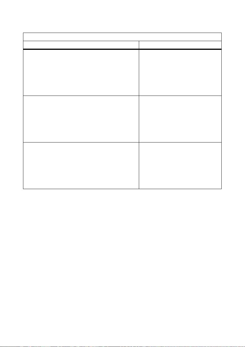
Paramètres et messages d’erreur SMA Solar Technology AG
Paramètre « Mise à la terre du module requise ? » / « Md.GndMdt »
Réglage : Non / No Cause / Solution
• Numéro d’événement 35
• Message à l’écran
< Résistance isolement - Vérif. générateur >
• La DEL rouge est allumée en continu.
• La DEL verte est allumée en continu
• L’onduleur alimente le réseau.
• Numéro d’événement 35
• Message à l’écran
< Résistance isolement - Vérif. générateur >
• La DEL rouge est allumée en continu.
• La DEL verte est allumée en continu
• L’onduleur alimente le réseau.
• Numéro d’événement 42
• Message à l’écran
< MAT incorrecte, vérifier set de MAT >
• La DEL rouge est allumée en continu.
• La DEL verte est allumée en continu
• L’onduleur alimente le réseau.
Une surtension est survenue.
• Réparez l’erreur, comme décrit au
chapitre 6.3.3«Réparer les
défauts d’isolement» (Page58).
Un défaut d’isolement est survenu.
• Réparez l’erreur, comme indiqué
au chapitre 6.3.3«Réparer les
défauts d’isolement» (Page58).
Le SMA Plug-in Grounding est raccordé
avec les pôles inversés ou en panne.
• Réparez l’erreur, comme indiqué
au chapitre 6.3.4«Corriger le
type de mise à la terre»
(Page58).
56 Erdung_HF-IXX105020 Instructions d’installation
Page 57

SMA Solar Technology AG Paramètres et messages d’erreur
6.3 Résolution des erreurs
6.3.1 Sécurité
DANGER !
Danger de mort par choc électrique !
L’onduleur fonctionne sous haute tension.
• Déconnecter l’onduleur côtés AC et DC, comme décrit dans le guide d’installation de
l’onduleur.
6.3.2 Réparer la panne du fusible
Procédez comme suit pour réparer la panne < Dysfonctionnement du fusible de terre - Vérif. fusible
terre > :
1. Déconnecter l’onduleur côtés AC et DC, comme décrit dans le guide d’installation de
l’onduleur.
2. Noter le t ype de m ise à la t erre du g éné rat eur (« − » ou « + ») et t ire r le S MA P lug- in G rou ndi ng
vers le bas.
3. Vérifier si le générateur PV présente un défaut à la terre, comme décrit dans le guide
d’installation de l’onduleur, et éventuellement éliminer le défaut à la terre.
4. Remettre l’onduleur en marche sans le SMA Plug-in Grounding, comme décrit dans le guide
d’installation de l’onduleur.
☑ L’onduleur teste si le défaut à la terre est toujours présent.
– Si aucun défaut à la terre n’est présent, le message d’erreur
< Dysfonctionnement du fusible de terre > se change en < Résistance isolement > dès
que la tension de départ atteint les 220 V.
– Si un défaut à la terre est présent, le message d’erreur < Dysfonctionnement du fusible
de terre > demeure. Dans un tel cas, répéter les étapes 3 et 4.
5. Déconnecter l’onduleur côtés AC et DC, comme décrit dans le guide d’installation de
l’onduleur.
6. Tester et éventuellement remplacer le fusible du SMA Plug-in Grounding, comme indiqué au
chapitre 5«Contrôle et remplacement du fusible du SMA Plug-in Grounding» (Page50).
7. Raccorder un SMA Plug-in Grounding en bon état à l’onduleur, comme indiqué au chapitre
4«Installation du SMA Plug-in Grounding» (Page48).
8. Remettre l’onduleur en marche, comme décrit dans le guide d’installation de l’onduleur.
L’onduleur teste alors si le type de mise à la terre défini correspond à celui du SMA Plug-in
Grounding installé.
☑ Après sa remise en service, l’onduleur se remet à injecter dans le réseau.
Instructions d’installation Erdung_HF-IXX105020 57
Page 58

Paramètres et messages d’erreur SMA Solar Technology AG
6.3.3 Réparer les défauts d’isolement
Procédez comme suit pour réparer la panne < Résistance isolement - Vérif. générateur > :
1. Déconnecter l’onduleur côtés AC et DC, comme décrit dans le guide d’installation de
l’onduleur.
2. Si un SMA Plug-in Grounding est raccordé, noter le type de mise à la terre du générateur
(« − » ou « + ») et tirer le SMA Plug-in Grounding vers le bas.
3. Vérifier si le générateur PV présente un défaut à la terre, comme décrit dans le guide
d’installation de l’onduleur, et éventuellement éliminer le défaut à la terre.
4. Tester et éventuellement remplacer le fusible du SMA Plug-in Grounding, comme indiqué au
chapitre 5«Contrôle et remplacement du fusible du SMA Plug-in Grounding» (Page50).
5. Raccorder un SMA Plug-in Grounding en bon état à l’onduleur, comme indiqué au
chapitre4«Installation du SMA Plug-in Grounding» (Page48).
6. Remettez l’onduleur en marche, comme indiqué dans le guide d’installation de l’onduleur.
☑ L'onduleur teste alors si le défaut à la terre encore existe et si le type de mise à la terre défini
correspond à celui du SMA Plug-in Grounding installé.
– Si le défaut à la terre persiste, le message d’erreur < Résistance isolement - Vérif.
générateur > demeure. Dans un tel cas, répétez les étapes 3 à 6.
– S’il n’existe plus de défaut à la terre, le message d’erreur < Résistance isolement - Vérif.
générateur > disparaît et l’onduleur injecte à nouveau dans le réseau.
– Si une mise à la terre positive ou négative est obligatoire et le SMA Plug-in Grounding a
été raccordé avec une polarité incorrecte, le message d'erreur < MAT incorrecte, vérifier
set de MAT > apparaît. Continuez à partir du chapitre 6.3.4«Corriger le type de mise
à la terre» (Page58).
☑ Après sa remise en service, l’onduleur se remet à injecter dans le réseau.
6.3.4 Corriger le type de mise à la terre
Procédez comme suit pour réparer la panne < MAT incorrecte, vérifier set de MAT > :
1. Déconnecter l’onduleur côtés AC et DC, comme décrit dans le guide d’installation de
l’onduleur.
2. Raccorder un SMA Plug-in Grounding en bon état à l’onduleur avec une polarité correcte,
comme indiqué au chapitre 4«Installation du SMA Plug-in Grounding» (Page48).
3. Remettre l’onduleur en marche, comme décrit dans le guide d’installation de l’onduleur.
L’onduleur teste alors si le type de mise à la terre correspond au type défini ou assimilé.
☑ L’erreur est réparée et l’onduleur se remet à injecter dans le réseau.
58 Erdung_HF-IXX105020 Instructions d’installation
Page 59

SMA Solar Technology AG Contact
7 Contact
En cas de problèmes techniques concernant nos produits, prenez contact avec le Service en Ligne
SMA. Nous avons besoin des données suivantes afin de pouvoir vous aider de manière ciblée :
• Type d’onduleur
• Numéro de série de l’onduleur
• Panneaux photovoltaïques connectés et nombre de panneaux photovoltaïques
• Type de mise à la terre (positif ou négatif)
• Numéro d’événement ou message à l’écran de l’onduleur
• Équipement optionnel (par ex. appareils de communication)
• Le cas échéant, type du relais multifonction raccordé
SMA France S.A.S.
Le Parc Technologique de Lyon
240 Allée Jacques Monod - Bât. M2
69791 Saint Priest cedex
www.SMA-France.com
Service en Ligne de SMA
Onduleur: +33 4 72 09 04 40
Communication: +33 4 72 09 04 41
Fax: +33 4 72 22 97 10
E-mail: Serviceline@SMA-France.com
Instructions d’installation Erdung_HF-IXX105020 59
Page 60

Dispositions légales SMA Solar Technology AG
Les informations figurant dans ces documents sont la propriété exclusive de SMA Solar Technology AG. La publication de ces
informations en totalité ou en partie doit être soumise à l'accord préalable de SMA Solar Technology AG. Une reproduction
interne au profit de l'entreprise, pour l'évaluation et la mise en service conforme du produit est autorisée sans accord préalable.
Clause de non-responsabilité
En principe, les conditions générales de livraison de SMA Solar Technology AG s'appliquent.
Le contenu de ces documents est régulièrement contrôlé et, le cas échéant, adapté. Des divergences ne peuvent néanmoins être
exclues. L’exhaustivité des documents n’est pas garantie. La version actuellement en vigueur peut être consultée sur le site Internet
www.SMA.de ou être obtenue par les réseaux de distribution habituels.
Aucune garantie ni responsabilité ne s’applique lors de dommages quels qu’ils soient, si ceux-ci sont dus à une ou plusieurs des
causes suivantes :
• Transport incorrect
• Utilisation du produit inappropriée ou non conforme aux instructions d’utilisation
• Emploi du produit dans un environnement non prévu
• Emploi du produit sans prise en compte des dispositions légales de sécurité pertinentes sur le lieu d’utilisation
• Non-respect des consignes d’alarme et de sécurité décrites dans l’ensemble de la documentation pertinente du produit
• Emploi du produit dans de mauvaises conditions de sécurité et de protection
• Modification arbitraire ou réparation du produit ou du logiciel livré conjointement
• Dysfonctionnement du produit dû à l’influence d’un appareil branché ou placé à proximité hors des limites autorisées
• Catastrophe ou cas de force majeure
L’utilisation des logiciels livrés et créés par SMA Solar Technology AG est aussi soumise aux conditions suivantes :
• La SMA Solar Technology AG décline toute responsabilité quant aux dommages découlant directement ou indirectement de
l’utilisation du logiciel fabriqué par SMA Solar Technology AG. Ceci s’applique également à la prestation ou au défaut de
prestation de services d’après-vente
• Le logiciel livré conjointement, qui n’a pas été créé par SMA Solar Technology AG, est soumis aux accords de licence et de
responsabilité correspondants du fabricant.
Garantie usine SMA
Les conditions de garantie actuelles sont livrées avec votre appareil. Vous pouvez également, si besoin est, les télécharger sur le
site Internet www.SMA.de ou les obtenir sous forme papier par le par les réseaux de distribution habituels.
Marque déposée
Toutes les marques déposées sont reconnues, y compris lorsqu’elles ne sont pas mentionnées expressément. L'absence de
l'emblème de marque ne signifie pas qu'un produit ou une marque puisse être librement commercialisé.
La marque verbale et les logos Bluetooth
marques par la société SMA Solar Technology AG s’effectue sous licence.
SMA Solar Technology AG
Sonnenallee 1
34266 Niestetal
Allemagne
Tél. +49 561 9522-0
Fax +49 561 9522-100
www.SMA.de
e-mail : info@SMA.de
© 2004 à 2010 SMA Solar Technology AG. Tous droits réservés.
®
sont des marques déposées de la société Bluetooth SIG, Inc et toute utilisation de ces
60 Erdung_HF-IXX105020 Instructions d’installation
Page 61

Page 62

Índice SMA Solar Technology AG
Índice
1 Indicaciones para el uso de estas instrucciones . . . . . . . 63
1.1 Validez . . . . . . . . . . . . . . . . . . . . . . . . . . . . . . . . . . . . . . . . . . . 63
1.2 Grupo destinatario . . . . . . . . . . . . . . . . . . . . . . . . . . . . . . . . . . 63
1.3 Información adicional. . . . . . . . . . . . . . . . . . . . . . . . . . . . . . . . 63
1.4 Símbolos utilizados . . . . . . . . . . . . . . . . . . . . . . . . . . . . . . . . . . 64
2 Seguridad . . . . . . . . . . . . . . . . . . . . . . . . . . . . . . . . . . . . . . 65
2.1 Uso previsto . . . . . . . . . . . . . . . . . . . . . . . . . . . . . . . . . . . . . . . 65
2.2 Indicaciones de seguridad . . . . . . . . . . . . . . . . . . . . . . . . . . . . 66
3 Volumen de suministro . . . . . . . . . . . . . . . . . . . . . . . . . . . 67
4 Instalar el SMA Plug-in Grounding. . . . . . . . . . . . . . . . . . 68
5 Comprobar y cambiar los fusibles del SMA
Plug-in Grounding . . . . . . . . . . . . . . . . . . . . . . . . . . . . . . . 70
6 Parámetros y alarmas de error . . . . . . . . . . . . . . . . . . . . 73
6.1 Parámetros ajustables. . . . . . . . . . . . . . . . . . . . . . . . . . . . . . . . 73
6.1.1 Parámetro "¿Toma a tierra del módul prescrita?" o "GndMdt". . . . . . . . . . . 73
6.1.2 Parámetro "Tipo de toma a tierra prescrita" o "Md.GndModReq" . . . . . . . . 74
6.2 Alarmas de error. . . . . . . . . . . . . . . . . . . . . . . . . . . . . . . . . . . . 75
6.3 Eliminar errores. . . . . . . . . . . . . . . . . . . . . . . . . . . . . . . . . . . . . 77
6.3.1 Seguridad . . . . . . . . . . . . . . . . . . . . . . . . . . . . . . . . . . . . . . . . . . . . . . . . . . . 77
6.3.2 Eliminar el fallo del fusible de toma a tierra . . . . . . . . . . . . . . . . . . . . . . . . . 77
6.3.3 Eliminar fallo de aislamiento . . . . . . . . . . . . . . . . . . . . . . . . . . . . . . . . . . . . . 78
6.3.4 Corregir tipo de puesta a tierra . . . . . . . . . . . . . . . . . . . . . . . . . . . . . . . . . . 78
7 Contacto . . . . . . . . . . . . . . . . . . . . . . . . . . . . . . . . . . . . . . . 79
62 Erdung_HF-IXX105020 Instrucciones de instalación
Page 63

SMA Solar Technology AG Indicaciones para el uso de estas instrucciones
1 Indicaciones para el uso de estas instrucciones
1.1 Validez
Estas instrucciones describen la conexión del kit de puesta a tierra SMA Plug-in Grounding y el
cambio de los fusibles en el SMA Plug-in Grounding.
Sólo debe usar el SMA Plug-in Grounding con los siguientes inversores de SMA:
• Sunny Boy 2000HF (SB 2000HF-30),
• Sunny Boy 2500HF (SB 2500HF-30),
• Sunny Boy 3000HF (SB 3000HF-30).
Guarde siempre estas instrucciones en un lugar de fácil acceso.
1.2 Grupo destinatario
Estas instrucciones están destinadas a instaladores eléctricos cualificados. Las actividades descritas
en estas instrucciones sólo deben ser realizadas por instaladores eléctricos cualificados.
1.3 Información adicional
Encontrará información detallada sobre la instalación, la puesta en servicio, el mantenimiento y la
búsqueda de fallos del inversor en las instrucciones de instalación correspondientes.
Instrucciones de instalación Erdung_HF-IXX105020 63
Page 64

Indicaciones para el uso de estas instrucciones SMA Solar Technology AG
1.4 Símbolos utilizados
En estas instrucciones se utilizan los siguientes tipos de indicaciones de seguridad e indicaciones
generales:
¡PELIGRO!
G
"¡PELIGRO!" representa una indicación de seguridad que, de no ser observada, causará
directamente la muerte o lesión corporal grave.
¡ADVERTENCIA!
¡"ADVERTENCIA"! representa una indicación de seguridad que, de no ser observada,
puede causar la muerte o lesión corporal grave.
¡ATENCIÓN!
¡"ATENCIÓN" representa una indicación de seguridad que, de no ser observada, puede
causar lesión corporal leve o media!
¡PRECAUCIÓN!
¡"PRECAUCIÓN" representa una indicación de seguridad que, de no ser observada,
puede causar daños materiales!
Indicación
Las indicaciones representan información importante para el funcionamiento óptimo del
producto.
☑ Este símbolo representa el resultado de una acción.
64 Erdung_HF-IXX105020 Instrucciones de instalación
Page 65

SMA Solar Technology AG Seguridad
2 Seguridad
2.1 Uso previsto
Si utiliza tecnologías de células solares especiales en su generador FV, p. ej. módulos FV de capa
fina o de contacto trasero, puede ser necesario que conectar a tierra el polo positivo o el polo
ne gat ivo de l a in sta lac ión FV. Con el SMA Plu g-i n Gr oun din g se puede conectar a tierra el generador
FV. El set de puesta a tierra enchufable es adecuado para los inversores del tipo SB 2000HF-30,
SB 2500HF-30 y SB 3000HF-30. Mediante esta puesta a tierra interna del equipo se consigue un
funcionamiento duradero y seguro con unas características CEM óptimas y la minimización de los
costes de instalación.
El SMA Plug-in Grounding incluye un fusible de 1 A como protección contra el peligro de incendio y
un conmutador que ajusta la monitorización de aislamiento del inversor al SMA Plug-in Grounding.
El SMA Plug-in Grounding establece, a través del fusible, una conexión directa entre el polo que se
va a conectar a tierra (positivo o negativo) de los módulos FV y la conexión a tierra del inversor.
Si se produce un cortocircuito a tierra, el fusible interrumpe la corriente de fallo en el SMA Plug-in
Grounding.
El fabricante del módulo puede proporcionarle información acerca del tipo y la necesidad de la
puesta a tierra del módulo en su instalación FV.
El inversor sólo debe conectarse a generadores fotovoltaicos (módulos y cableado) que estén
montados con aislamiento de protección (clase de protección II).
El SMA Plu g-i n Gr ound ing es a pro pia do e xcl usi vam ent e par a su utilización en los inversores de SMA
del tipo Sunny Boy 2000HF/2500HF/3000HF.
Instrucciones de instalación Erdung_HF-IXX105020 65
Page 66

Seguridad SMA Solar Technology AG
2.2 Indicaciones de seguridad
¡PELIGRO!
¡Peligro de muerte por altas tensiones en el inversor!
• Todos los trabajos en el inversor y la conexión del SMA Plug-in Grounding deberán
ser realizados exclusivamente por un instalador eléctrico cualificado.
¡PELIGRO!
Peligro de electrocución debido a altas tensiones en el inversor.
• Desconecte el inversor en los lados de CA y de CC tal y como se describe en las
instrucciones de instalación del inversor antes de conectar el SMA Plug-in
Grounding.
¡PRECAUCIÓN!
¡Daños en el SMA Plug-in Grounding o en el inversor por conexión defectuosa!
La conexión defectuosa del SMA Plug-in Grounding puede causar cortocircuitos y daños
ir rep ara bles en e l SM A Pl ug- in Groun din g y e n el inverso r. L a garantía del equipo quedará
anulada.
• Conecte el SMA Plug-in Grounding tal y como se describe en los siguientes
capítulos.
Conexión de los componentes conductivos de la subestructura del generador FV
con el sistema de puesta a tierra
Algunos fabricantes de módulos exigen la puesta a tierra de uno de los polos del
generador para evitar así las diferencias de potencial entre el potencial a tierra del kit de
puesta a tierra y del área del generador FV. Estas diferencias de potencial se evitan
gracias a la puesta a tierra de la subestructura del generador FV. Adicionalmente, esta
compensación de potencial ofrece máxima protección, a través del fusible integrado del
kit de puesta a tierra.
66 Erdung_HF-IXX105020 Instrucciones de instalación
Page 67

SMA Solar Technology AG Volumen de suministro
3 Volumen de suministro
Compruebe que el volumen de suministro esté completo y que no presente daños visibles externos.
Si falta algún componente o ve algún daño, póngase en contacto con su proveedor.
Componente Cantidad Descripción
A 1 SMA Plug-in Grounding
B 1 Instrucciones de instalación
Instrucciones de instalación Erdung_HF-IXX105020 67
Page 68

Instalar el SMA Plug-in Grounding SMA Solar Technology AG
4 Instalar el SMA Plug-in Grounding
Si se produce un cortocircuito a tierra en la instalación FV, el fusible interrumpe la corriente de fallo
que se ha generado en el SMA Plug-in Grounding.
La puesta a tierra positiva o negativa del inversor está codificada en el SMA Plug-in Grounding. Sólo
debe poner el inversor en marcha si ha instalado el SMA Plug-in Grounding correspondiente a la
puesta a tierra de su instalación FV.
Área de conexión
El área de conexión del SMA Plug-in Grounding se
encuentra en la parte inferior del inversor.
Procedimiento
1. Desconecte el inversor en los lados de CA y de CC tal y como se describe en las instrucciones
de instalación del inversor.
2. Compruebe que el SMA Plug-in Grounding esté
bien atornillado: sujete la pieza de conexión y tire
de la tapa con la mano.
☑ El SMA Plug-in Grounding está cerrado
firmemente, cuando los símbolos de la pieza de
conexión y de la tapa forman una cerradura.
68 Erdung_HF-IXX105020 Instrucciones de instalación
Page 69
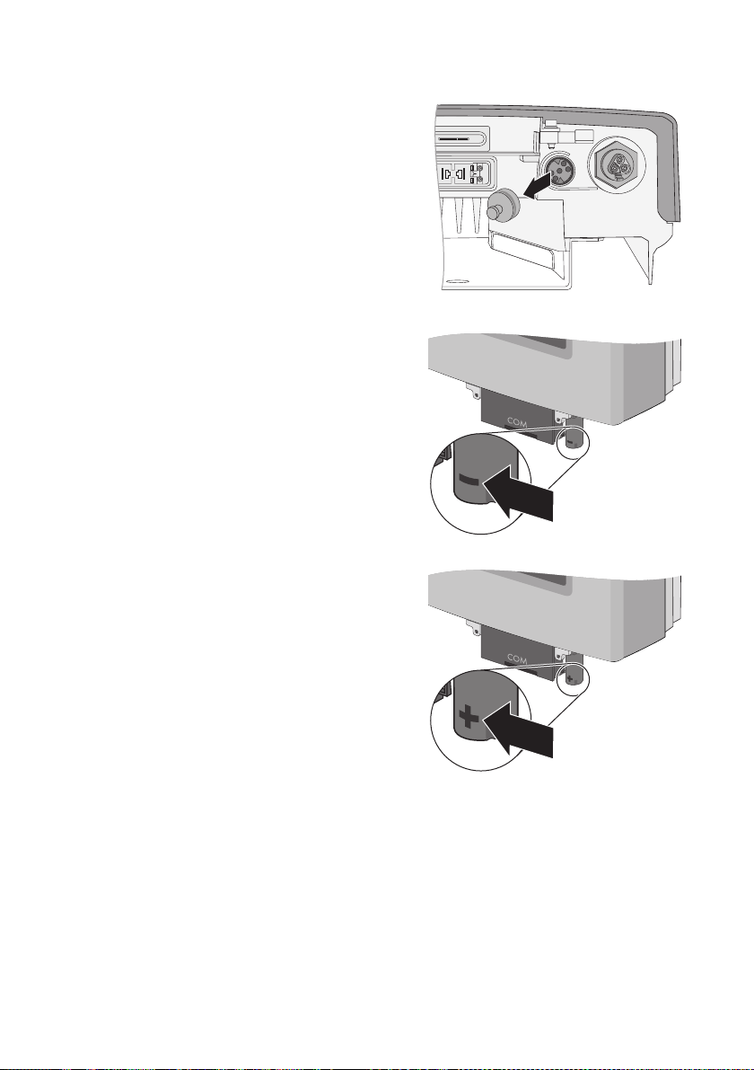
SMA Solar Technology AG Instalar el SMA Plug-in Grounding
3. Retirar la tapa de protección de la conexión del
inversor.
4. Si el polo negativo de la instalación FV debe
ser puesto a tierra:
– Coloque el SMA Plug-in Grounding en el
cl avi jer o de for ma q ue e l sí mbo lo " −" de la t apa
señale hacia delante.
– Presione el SMA Plug-in Grounding hacia
arriba hasta que encaje.
5. Si el polo positivo de la instalación FV debe ser
puesto a tierra:
– Coloque el SMA Plug-in Grounding en el
cl avi jer o de for ma q ue e l sí mbo lo " +" de la t apa
señale hacia delante.
– Presione el SMA Plug-in Grounding hacia
arriba hasta que encaje.
☑ El SMA Plug-in Grounding está instalado.
Instrucciones de instalación Erdung_HF-IXX105020 69
Page 70

Comprobar y cambiar los fusibles del SMA Plug-in Grounding SMA Solar Technology AG
5 Comprobar y cambiar los fusibles del SMA Plug-in Grounding
Si se produce un cortocircuito a tierra en la instalación FV, el SMA Plug-in Grounding reacciona en
función de la fuerza de la corriente de fallo:
•El fusible del SMA Plug-in Grounding interrumpe una corriente de fallo que se produce de
forma repentina. El fusible queda destruido.
• El inversor acusa corrientes de fallo que aparecen de forma insidiosa (véase el capítulo
6.2“Alarmas de error” (Página75)). Si elimina el cortocircuito a tierra a tiempo evitará la
destrucción del fusible.
Tras haber eliminado el cortocircuito a tierra (véase las instrucciones de instalación del inversor),
debe controlar el fusible del SMA Plug-in Grounding y cambiarlo si procede. Podrá obtener un fusible
nuevo de SMA Solar Technology AG (N.º de pedido KLKD-1).
¡ADVERTENCIA!
Peligro de incendio por fusibles inadecuados
• Utilice únicamente fusibles del tipo Littelfuse KLKD-1, para mantener la protección
contra incendio.
Procedimiento
1. Desconecte el inversor en los lados de CA y de CC tal y como se describe en las instrucciones
de instalación del inversor.
2. Antes de cambiar el fusible anote el tipo de la puesta a tierra del generador (" − " o "+").
3. Retire el SMA Plug-in Grounding tirando hacia
abajo.
4. Sujete la pieza de conexión del SMA Plug-in
Grounding y suelte y retire la tapa.
70 Erdung_HF-IXX105020 Instrucciones de instalación
Page 71
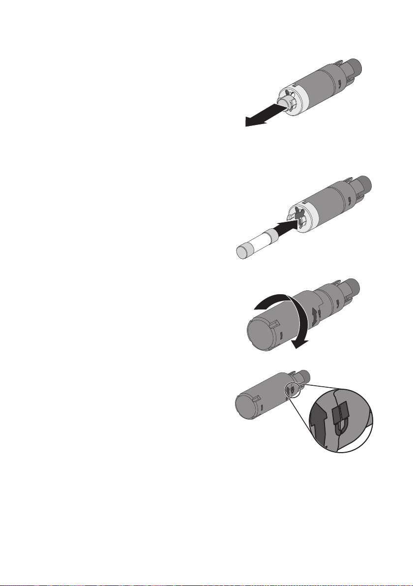
SMA Solar Technology AG Comprobar y cambiar los fusibles del SMA Plug-in Grounding
5. Extraiga el fusible del portafusibles del SMA Plug‑in
Grounding con unas tenazas.
6. Compruebe el estado del fusible con un aparato
de medición apropiado (prueba de continuidad).
☑ Cambiar el fusible si este está defectuoso.
7. Insertar presionando con fuerza un fusible con
capacidad de funcionamiento en el portafusibles
del SMA Plug-in Grounding.
8. Sujete la pieza de conexión del SMA Plug-in
Grounding y apriete la tapa con fuerza.
☑ El SMA Plug-in Grounding está cerrado
firmemente, cuando los símbolos de la pieza de
conexión y de la tapa forman una cerradura.
Instrucciones de instalación Erdung_HF-IXX105020 71
Page 72

Comprobar y cambiar los fusibles del SMA Plug-in Grounding SMA Solar Technology AG
9. Si el polo negativo de la instalación FV debe
ser puesto a tierra:
– Coloque el SMA Plug-in Grounding en el
cl avi jer o de for ma q ue e l sí mbo lo " −" de la t apa
señale hacia delante.
– Presione el SMA Plug-in Grounding hacia
arriba hasta que encaje.
10. Si el polo positivo de la instalación FV debe ser
puesto a tierra:
– Coloque el SMA Plug-in Grounding en el
cl avi jer o de for ma q ue e l sí mbo lo " +" de la t apa
señale hacia delante.
– Presione el SMA Plug-in Grounding hacia
arriba hasta que encaje.
☑El fusible del SMA Plug-in Grounding está cambiado.
72 Erdung_HF-IXX105020 Instrucciones de instalación
Page 73
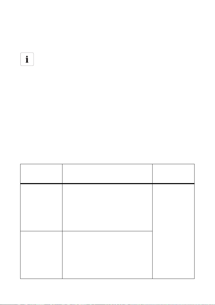
SMA Solar Technology AG Parámetros y alarmas de error
6 Parámetros y alarmas de error
6.1 Parámetros ajustables
Nombres de los parámetros en función del tipo de comunicación
Según el tipo de comunicación (Bluetooth o RS485) el inversor utiliza un protocolo de
comunicación diferente y los parámetros son representados de forma distinta:
• Comunicación mediante Bluetooth y Sunny Explorer: DATA II+
• Comunicación con RS485: DATA I
Hay 2 parámetros importantes para la puesta a tierra de la instalación FV, los cuales puede ajustar
en el inversor mediante un equipo de comunicación o un PC con el software correspondiente.
• Parámetro "¿Toma a tierra del módul prescrita?" (DATA II+) o "Md.GndMdt" (DATA I)
• Parámetro "Tipo de toma a tierra prescrita" (DATA II+) o "Md.GndModReq" (DATA I)
6.1.1 Parámetro "¿Toma a tierra del módul prescrita?" o "GndMdt"
La puesta a tierra del módulo es ajustable en el inversor mediante el parámetro "¿Toma a tierra del
módul prescrita?" o "Md.GndMdt". Tenga en cuenta las especificaciones del fabricante del módulo
y las directivas vigentes en el lugar de la instalación fotovoltaica.
Existen 2 opciones de ajuste:
Valor
(DATA II+ / DATA I)
No / No No hay ninguna especificación normativa ni del
Sí / Yes La puesta a tierra es obligatoria debido a
Instrucciones de instalación Erdung_HF-IXX105020 73
Explicación Valor
predeterminado
(DATA II+ / DATA I)
No / No
fabri cante de los mód ulos fotov oltaicos, por lo q ue
no es obligatorio realizar una puesta a tierra.
Puede conectar a tierra la instalación FV a pesar
de este ajuste.
En caso de error de toma a tierra el inversor sigue
inyectando. El inversor emite una advertencia con
el número de evento "35" como información.
especificaciones normativas o del fabricante de los
módulos fotovoltaicos. El inversor sólo puede ser
puesto en funcionamiento con el SMA Plug-in
Grounding.
En caso de error de toma a tierra el inversor deja
de inyectar y se bloquea. El inversor emite un fallo
de aislamiento con el número de evento "35".
Page 74

Parámetros y alarmas de error SMA Solar Technology AG
6.1.2 Parámetro "Tipo de toma a tierra prescrita" o "Md.GndModReq"
Mediante el parámetro "Tipo de toma a tierra prescrita" o "Md.GndModReq" puede fijar el tipo de
puesta a tierra deseado. Este parámetro viene ajustado de fábrica en "Aprendiendo" o en
"GndModLrn".
Existen 2 opciones para fijar este parámetro:
• Automático: en el modo aprendizaje el inversor memoriza el tipo de puesta a tierra del
SMA Plug-in Grounding que está conectado automáticamente tras 10 horas de funcionamiento.
• Manual: puede cambiar el tipo de puesta a tierra deseado mediante la comunicación
(Bluetooth/RS485), tras haber puesto el inversor en funcionamiento. También es posible
realizar el ajuste manual del parámetro sin el SMA Plug-in Grounding.
Existen 4 opciones de ajuste:
Valor
Explicación Valor
(DATA II+ / DATA I)
Positivo / GndModPs El inversor sólo permite una puesta a tierra
positiva.
Negativo / GndModNg El inversor sólo permite una puesta a tierra
negativa.
Nada prescrito /
GndModNoneReq
No hay ningún tipo de puesta a tierra prescrito.
El inversor puede ser puesto en funcionamiento
con o sin toma a tierra.
Aprendiendo /
GndModLrn
El inversor monitoriza la toma a tierra y tras
10 horas de funcionamiento con el SMA PlugGrounding conectado memoriza el tipo de la
toma a tierra.
El inversor puede ser puesto en funcionamiento
con o sin toma a tierra.
predeterminado
(DATA II+ / DATA I)
Aprendiendo /
GndModLrn
in
74 Erdung_HF-IXX105020 Instrucciones de instalación
Page 75

SMA Solar Technology AG Parámetros y alarmas de error
6.2 Alarmas de error
Eliminar siempre los errores
Elimine los errores que aparecen inmediatamente, aunque el inversor siga inyectando a
red.
El inversor actúa de formas distintas dependiendo del ajuste del parámetro "¿Toma a tierra del módul
prescrita?" o "Md.GndMdt".
Pueden aparecer las siguientes alarmas de error:
Parámetro "¿Toma a tierra del módul prescrita?" / "Md.GndMdt"
Ajuste: Sí / Yes Causa / remedio
• Número de evento 35
• Aviso del display
< Fallo fusible tierra - Comprob. fus. tierra >
• El LED rojo permanece encendido
• El LED verde parpadea o se apaga.
• El inversor no inyecta a red.
• Número de evento 35
• Aviso del display
< Resist. aislamiento - Comprobar generador >
• El LED rojo permanece encendido
• El LED verde parpadea o se apaga.
• El inversor no inyecta a red.
• Número de evento 42
• Aviso del display
< Tierra incorrecta, comprobar kit tierra >
• El LED rojo permanece encendido
• El LED verde parpadea o se apaga.
• El inversor no inyecta a red.
Se ha producido sobrecorriente.
• Elimine el error según se describe
en el capítulo 6.3.2“Eliminar el
fallo del fusible de toma a tierra”
(Página77).
Hay un fallo de aislamiento.
• Si está instalado un SMA Plug-in
Grounding, elimine el error según
se describe en el
capítulo6.3.3“Eliminar fallo de
aislamiento” (Página78).
• Si falta el SMA Plug-in Grounding,
conéctelo a continuación tal y
como se describe en el
capítulo4“Instalar el SMA Plug-in
Grounding” (Página68).
El SMA Plug-in Grounding está
conectado con los polos invertidos o
falta.
• Elimine el error según se describe
en el capítulo 6.3.4“Corregir tipo
de puesta a tierra” (Página78).
Instrucciones de instalación Erdung_HF-IXX105020 75
Page 76

Parámetros y alarmas de error SMA Solar Technology AG
Parámetro "¿Toma a tierra del módul prescrita?" / "Md.GndMdt"
Ajuste: No / No Causa / remedio
• Número de evento 35
• Aviso del display
< Resist. aislamiento - Comprobar generador >
• El LED rojo permanece encendido
• El LED verde permanece encendido
• El inversor inyecta a red.
• Número de evento 35
• Aviso del display
< Resist. aislamiento - Comprobar generador >
• El LED rojo permanece encendido
• El LED verde permanece encendido
• El inversor inyecta a red.
• Número de evento 42
• Aviso del display
< Tierra incorrecta, comprobar kit tierra >
• El LED rojo permanece encendido
• El LED verde permanece encendido
• El inversor inyecta a red.
Se ha producido sobrecorriente.
• Elimine el error según se describe
en el capítulo 6.3.3“Eliminar fallo
de aislamiento” (Página78).
Hay un fallo de aislamiento.
• Elimine el error según se describe
en el capítulo 6.3.3“Eliminar fallo
de aislamiento” (Página78).
El SMA Plug-in Grounding está
conectado con los polos invertidos o
falta.
• Elimine el error según se describe
en el capítulo 6.3.4“Corregir tipo
de puesta a tierra” (Página78).
76 Erdung_HF-IXX105020 Instrucciones de instalación
Page 77

SMA Solar Technology AG Parámetros y alarmas de error
6.3 Eliminar errores
6.3.1 Seguridad
¡PELIGRO!
¡Peligro de muerte por electrocución!
El inversor trabaja con tensiones altas.
• Desconecte el inversor en los lados de CA y de CC tal y como se describe en las
instrucciones de instalación del inversor.
6.3.2 Eliminar el fallo del fusible de toma a tierra
Proceda como sigue para eliminar el fallo < Fallo fusible tierra - Comprob. fus. tierra >:
1. Desconecte el inversor en los lados de CA y de CC tal y como se describe en las instrucciones
de instalación del inversor.
2. Anote el tipo de la puesta a tierra del generador (" − " o "+") y retire el SMA Plug-in Grounding
tirando hacia abajo.
3. Compruebe si hay un cortocircuito a tierra en el generador FV, tal y como se describe en las
instrucciones de instalación del inversor y elimínelo si procede.
4. Vuelva a poner en funcionamiento el inversor sin el SMA Plug-in Grounding tal y como se
describe en las instrucciones de instalación del inversor.
☑ El inversor comprueba si aún persiste el cortocircuito a tierra.
– Si ya no hay cortocircuito a tierra, la alarma de error < Fallo fusible tierra > cambia a
< Resist. aislamiento > en cuanto la tensión de arranque alcanza los 220 V.
– Si el cortocircuito a tierra persiste, permanece la alarma de error < Fallo fusible tierra >.
En este caso, repita los pasos 3 y 4.
5. Desconecte el inversor en los lados de CA y de CC tal y como se describe en las instrucciones
de instalación del inversor.
6. Compruebe e l fusible d el SMA P lug-in Gro unding y cámbie lo si procede tal y como se describe
en el capítulo 5“Comprobar y cambiar los fusibles del SMA Plug-in Grounding” (Página70).
7. Conecte un SMA Plug-in Grounding con capacidad de funcionamiento al inversor, tal y como
se describe en el capítulo 4“Instalar el SMA Plug-in Grounding” (Página68).
8. Vuelva a poner en funcionamiento el inversor tal y como se describe en las instrucciones de
instalación del inversor. Así el inversor comprueba si el tipo de puesta a tierra ajustado,
concuerda con el tipo de puesta a tierra del SMA Plug-in Grounding instalado.
☑ Tras la puesta en marcha, el inversor vuelve a inyectar a la red.
Instrucciones de instalación Erdung_HF-IXX105020 77
Page 78

Parámetros y alarmas de error SMA Solar Technology AG
6.3.3 Eliminar fallo de aislamiento
Proceda como sigue para eliminar el fallo < Resist. aislamiento - Comprobar generador >:
1. Desconecte el inversor en los lados de CA y de CC tal y como se describe en las instrucciones
de instalación del inversor.
2. Si hay un SMA Plug-in Grounding conectado, anote el tipo de la puesta a tierra del generador
(" − " o "+") y retire el SMA Plug-in Grounding tirando hacia abajo.
3. Compruebe si hay un cortocircuito a tierra en el generador FV, tal y como se describe en las
instrucciones de instalación del inversor y elimínelo si procede.
4. Compruebe e l fusible d el SMA P lug-in Gro unding y cámbie lo si procede tal y como se describe
en el capítulo 5“Comprobar y cambiar los fusibles del SMA Plug-in Grounding” (Página70).
5. Conecte un SMA Plug-in Grounding con capacidad de funcionamiento al inversor, tal y como
se describe en el capítulo 4“Instalar el SMA Plug-in Grounding” (Página68).
6. Vuelva a poner en funcionamiento el inversor tal y como se describe en las instrucciones de
instalación del inversor.
☑ Así, el inversor comprueba si todavía persiste un cortocircuito a tierra y si el tipo de puesta
a tierra ajustado concuerda con el tipo de puesta a tierra del SMA Plug-in Grounding
instalado.
– Si el cortocircuito a tierra persiste, el aviso de error < Resist. aislamiento - Comprobar
generador > permanece. En este caso, repita los pasos 3 y 6.
– Si se ha eliminado el cortocircuito a tierra, el aviso de error <Resist. aislamiento -
Comprobar generador > desaparece y el inversor vuelve a inyectar a la red.
– En caso de que sea obligatoria una puesta a tierra positiva o negativa y el SMA Plug-in
Grounding esté conectado con una polaridad errónea, aparecerá un aviso de error
<Tierra incorrecta, comprobar kit tierra >. Prosiga con el capítulo 6.3.4“Corregir tipo
de puesta a tierra” (Página78).
☑ Tras la puesta en marcha, el inversor vuelve a inyectar a la red.
6.3.4 Corregir tipo de puesta a tierra
Proceda como sigue para eliminar el fallo < Tierra incorrecta, comprobar kit tierra >:
1. Desconecte el inversor en los lados de CA y de CC tal y como se describe en las instrucciones
de instalación del inversor.
2. Conecte un SMA Plug-in Grounding con capacidad de funcionamiento y con la polaridad
correcta al inversor, tal y como se describe en el capítulo 4“Instalar el SMA Plug-in
Grounding” (Página68).
3. Vuelva a poner en funcionamiento el inversor tal y como se describe en las instrucciones de
instalación del inversor. Así el inversor comprueba si el tipo de puesta a tierra concuerda con
el tipo de puesta a tierra ajustado o aprendido del SMA Plug-in Grounding instalado.
☑ El fallo ha sido eliminado y el inversor vuelve a inyectar a la red.
78 Erdung_HF-IXX105020 Instrucciones de instalación
Page 79

SMA Solar Technology AG Contacto
7 Contacto
Si tiene problemas técnicos con nuestros productos, póngase en contacto con la ayuda técnica de
SMA. Necesitamos los siguientes datos para poder ayudarle de manera concreta:
•Tipo de inversor
• Número de serie del inversor
• Tipo y número de módulos fotovoltaicos conectados
• Tipo de puesta a tierra (positiva o negativa)
• Número de evento o aviso del display del inversor
• Equipamiento opcional (p. ej. equipos de comunicación)
• en caso necesario, tipo de relé multifunción
SMA Ibérica Tecnología Solar, S.L.
Avda. de les Corts Catalanes, 9
Planta 3, Oficinas 17 – 18
08173 Sant Cugat del Vallès (Barcelona)
Tel. +34 900 14 22 22
Fax +34 936 75 32 14
Service@SMA-Iberica.com
www.SMA-Iberica.com
Instrucciones de instalación Erdung_HF-IXX105020 79
Page 80

Disposiciones legales SMA Solar Technology AG
Las informaciones contenidas en esta documentación son propiedad de SMA Solar Technology AG. La publicación, completa o
parcial, requiere el consentimiento por escrito de SMA Solar Technology AG. La reproducción interna por parte de una empresa
con vistas a evaluar el producto o emplearlo correctamente está permitida y no requiere autorización.
Exención de responsabilidad
Rigen por principio las condiciones generales de entrega de SMA Solar Technology AG.
El contenido de esta documentación se revisa y actualiza periódicamente. No obstante, no se excluyen posibles divergencias.
No garantizamos la integridad de la información contenida en este documento. La versión actual en cada momento puede
consultarse en la página www.SMA.de o solicitarse a través de las habituales vías comerciales.
Quedan excluidos en todos los casos las reclamaciones de garantía y de responsabilidad, si se deben a una o varias de las
siguientes causas:
• Daños de transporte
• Uso indebido del producto o no conforme a la finalidad por la que ha sido desarrollado
• Uso del producto en un entorno no previsto
• Uso del producto incumpliendo las normas de seguridad legales aplicables en el lugar de trabajo
• Incumplimiento de las indicaciones de seguridad y advertencias descritas en todos los documentos relevantes del producto
• Uso del producto bajo condiciones de seguridad y protección deficientes
• Modificación por cuenta propia o reparación del producto o del software suministrado
• Comportamiento incorrecto del producto por influencia de otros aparatos conec tados o m uy cerca nos qu e sup eren los val ores
límites legalmente permitidos
• Casos de catástrofes o de fuerza mayor
La utilización del software desarrollado por SMA Solar Technology AG está sujeta a las siguientes condiciones adicionales:
• SMA Solar Technology AG rechaza cualquier responsabilidad para daños sucesivos directos o indirectos causados por la
utilización del software desarrollado por SMA Solar Technology AG. Esto también se aplica en el caso de prestaciones o noprestaciones de asistencia.
• El software suministrado no desarrollado por SMA Solar Technology AG está sujeto a los correspondientes acuerdos de
licencia y responsabilidad de su fabricante.
Garantía de fábrica de SMA
Las condiciones actuales de garantía están incluidos en el suministro de su aparato. También pueden descargarse en la página
www.SMA.de o solicitarse a través de las habituales vías comerciales.
Marcas registradas
Se reconocen todas las marcas registradas, incluso si no están señaladas por separado. Las faltas de señalización no implican
que la mercancía o las marcas sean libres.
La marca y los logotipos de Bluetooth
través de SMA Solar Technology AG habrá de realizarse con la licencia correspondiente.
SMA Solar Technology AG
Sonnenalle 1
34266 Niestetal
Alemania
Tel. +49 561 9522-0
Fax +49 561 9522-100
www.SMA.de
Correo electrónico: info@SMA.de
© 2004 - 2010 SMA Solar Technology AG. Reservados todos los derechos.
®
son marcas registradas de Bluetooth SIG, Inc. Todo uso que se haga de estas marcas a
80 Erdung_HF-IXX105020 Instrucciones de instalación
Page 81

Page 82

Indice SMA Solar Technology AG
Indice
1 Avvertenze sull'impiego di queste istruzioni . . . . . . . . . . 83
1.1 Ambito di validità . . . . . . . . . . . . . . . . . . . . . . . . . . . . . . . . . . . 83
1.2 Destinatari. . . . . . . . . . . . . . . . . . . . . . . . . . . . . . . . . . . . . . . . . 83
1.3 Ulteriori informazioni . . . . . . . . . . . . . . . . . . . . . . . . . . . . . . . . 83
1.4 Simboli usati . . . . . . . . . . . . . . . . . . . . . . . . . . . . . . . . . . . . . . . 84
2 Sicurezza. . . . . . . . . . . . . . . . . . . . . . . . . . . . . . . . . . . . . . . 85
2.1 Utilizzo conforme . . . . . . . . . . . . . . . . . . . . . . . . . . . . . . . . . . . 85
2.2 Avvertenze di sicurezza . . . . . . . . . . . . . . . . . . . . . . . . . . . . . . 86
3 Fornitura . . . . . . . . . . . . . . . . . . . . . . . . . . . . . . . . . . . . . . . 87
4 Installazione di SMA Plug-in Grounding . . . . . . . . . . . . . 88
5 Verifica e sostituzione del fusibile di SMA Plug-in
Grounding . . . . . . . . . . . . . . . . . . . . . . . . . . . . . . . . . . . . . 90
6 Parametri e messaggi di errore . . . . . . . . . . . . . . . . . . . . 93
6.1 Parametri impostabili. . . . . . . . . . . . . . . . . . . . . . . . . . . . . . . . . 93
6.1.1 Parametro "Messa a terra modulare richiesta?“ o "GndMdt". . . . . . . . . . . . 93
6.1.2 Parametro "Tipo di messa a terra modulare richiesto" o "Md.GndModReq" 94
6.2 Messaggi di errore . . . . . . . . . . . . . . . . . . . . . . . . . . . . . . . . . . 95
6.3 Eliminazione di errori . . . . . . . . . . . . . . . . . . . . . . . . . . . . . . . . 97
6.3.1 Sicurezza . . . . . . . . . . . . . . . . . . . . . . . . . . . . . . . . . . . . . . . . . . . . . . . . . . . 97
6.3.2 Eliminazione di guasto al fusibile di terra . . . . . . . . . . . . . . . . . . . . . . . . . . . 97
6.3.3 Eliminazione dell'errore di isolamento . . . . . . . . . . . . . . . . . . . . . . . . . . . . . 98
6.3.4 Rettifica del tipo di messa a terra . . . . . . . . . . . . . . . . . . . . . . . . . . . . . . . . . 98
7 Contatto. . . . . . . . . . . . . . . . . . . . . . . . . . . . . . . . . . . . . . . . 99
82 Erdung_HF-IXX105020 Istruzioni per l’installazione
Page 83

SMA Solar Technology AG Avvertenze sull'impiego di queste istruzioni
1 Avvertenze sull'impiego di queste istruzioni
1.1 Ambito di validità
Le presenti istruzioni descrivono il collegamento del kit di messa a terra SMA Plug-in Grounding e la
sostituzione dei fusibili in SMA Plug-in Grounding.
L'impiego di SMA Plug-in Grounding è consentito solo per i seguenti inverter SMA:
• Sunny Boy 2000HF (SB 2000HF-30),
• Sunny Boy 2500HF (SB 2500HF-30),
• Sunny Boy 3000HF (SB 3000HF-30).
Le presenti istruzioni devono essere accessibili in qualsiasi momento.
1.2 Destinatari
Le presenti istruzioni sono destinate a tecnici abilitati. Le operazioni qui descritte devono essere
eseguite esclusivamente da tecnici abilitati.
1.3 Ulteriori informazioni
Per informazioni dettagliate su installazione, messa in servizio, manutenzione e ricerca errori
dell'inverter, consultare le istruzioni per l'installazione corrispondenti.
Istruzioni per l’installazione Erdung_HF-IXX105020 83
Page 84

Avvertenze sull'impiego di queste istruzioni SMA Solar Technology AG
1.4 Simboli usati
Nelle presenti istruzioni vengono utilizzati i seguenti tipi di simboli per avvertenze di sicurezza e
informazioni di carattere generale:
PERICOLO!
G
L'indicazione "PERICOLO" identifica un'avvertenza di sicurezza la cui inosservanza
provoca immediatamente lesioni gravi o mortali!
AVVERTENZA!
L'indicazione "AVVERTENZA" identifica un'avvertenza di sicurezza la cui inosservanza
può provocare lesioni gravi o mortali!
ATTENZIONE!
L'indicazione "ATTENZIONE" identifica un'avvertenza di sicurezza la cui inosservanza
può provocare lesioni leggere o medie!
AVVISO!
L'indicazione "AVVISO" identifica un'avvertenza di sicurezza la cui inosservanza può
provocare danni materiali!
Nota
Sono segnalate come note le informazioni rilevanti per il funzionamento ottimale del
prodotto.
☑ Questo simbolo indica il risultato di un'operazione effettuata.
84 Erdung_HF-IXX105020 Istruzioni per l’installazione
Page 85

SMA Solar Technology AG Sicurezza
2 Sicurezza
2.1 Utilizzo conforme
Se nel generatore FV vengono utilizzate tecnologie cellulari speciali, per esempio moduli FV a film
sottile o dotati di contatti sul lato posteriore, può essere necessaria la messa terra del polo positivo o
negativo dell'impianto FV. SMA Plug-in Grounding consente la messa a terra del generatore FV
nell'inverter. Il kit di messa a terra ad innesto è adatto agli inverter del tipo SB 2000HF-30,
SB 2500HF-30 e SB 3000HF-30. La messa a terra interna all'apparecchio garantisce sicurezza e
lunga durata dell'impianto, caratteristiche CEM ottimali e ridotti costi di installazione.
SMA Plug-in Grounding comprende un fusibile da 1 A come protezione contro il pericolo di incendio
e una commutazione che regola il monitoraggio dell'isolamento dell'inverter allo SMA Plug-in
Grounding. Tramite il fusibile SMA Plug-in Grounding collega direttamente il polo da mettere a terra
(positivo o negativo) dei moduli FV e il collegamento PE dell'inverter. Quando si verifica una
dispersione verso terra, il fusibile in SMA Plug-in Grounding interrompe la corrente di guasto.
Per informazioni sulle modalità e la necessità della messa a terra dei moduli nell'impianto FV,
rivolgersi al produttore dei moduli.
Il funzionamento dell'inverter è consentito solo su generatori FV (moduli e cablaggio) provvisti di
isolamento di protezione (classe di isolamento II).
SMA Plug-in Grounding può essere utilizzato esclusivamente in abbinamento agli inverter SMA del
tipo Sunny Boy 2000HF/2500HF/3000HF.
Istruzioni per l’installazione Erdung_HF-IXX105020 85
Page 86

Sicurezza SMA Solar Technology AG
2.2 Avvertenze di sicurezza
PERICOLO!
Pericolo di morte per alta tensione nell'inverter!
• Tutti i lavori sull'inverter e il collegamento di SMA Plug-in Grounding devono essere
eseguiti esclusivamente da tecnici abilitati.
PERICOLO!
Scossa elettrica per alta tensione nell'inverter!
• Prima di procedere al collegamento di SMA Plug-in Grounding, disinserire l'inverter
sul lato CA e CC come descritto nelle Istruzioni per l'installazione dell'inverter.
AVVISO!
Danneggiamento di SMA Plug-in Grounding o dell'inverter per collegamento
errato!
Un collegamento errato di SMA Plug-in Grounding può provocare cortocircuiti e danni
irreparabili a SMA Plug-in Grounding e all'inverter. Ciò comporta l'estinzione di tutti i diritti
derivanti dalla garanzia.
• Procedere al collegamento di SMA Plug-in Grounding come descritto nei capitoli
seguenti.
Collegamento di parti conduttive della sottostruttura del generatore FV con
l'impianto di messa a terra
Alcuni produttori di moduli richiedono la messa a terra di un polo del generatore per
prevenire le differenze di potenziale tra il potenziale di terra del kit di messa a terra e
l'ambiente del generatore FV. Le differenze di potenziale vengono evitate tramite la messa
a terra della sottostruttura del generatore FV. Inoltre tale collegamento equipotenziale
offre la migliore protezione grazie al fusibile integrato nel kit di messa a terra.
86 Erdung_HF-IXX105020 Istruzioni per l’installazione
Page 87
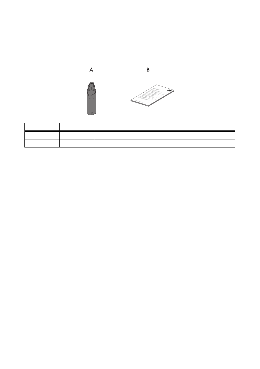
SMA Solar Technology AG Fornitura
3 Fornitura
Controllare che la fornitura sia completa e non presenti danni visibili all'esterno. Se si riscontrano
danni o la fornitura è incompleta, rivolgersi al proprio rivenditore.
Oggetto Quantità Descrizione
A 1 SMA Plug-in Grounding
B 1 Istruzioni per l'installazione
Istruzioni per l’installazione Erdung_HF-IXX105020 87
Page 88
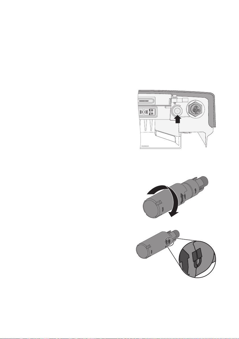
Installazione di SMA Plug-in Grounding SMA Solar Technology AG
4 Installazione di SMA Plug-in Grounding
Quando si verifica una dispersione verso terra nell'impianto FV, il fusibile in SMA Plug-in Grounding
interrompe la corrente di guasto generatasi.
Alla messa a terra positiva o negativa dell'inverter in SMA Plug-in Grounding è assegnato un codice.
L'inverter può essere pertanto messo in funzione solo quando SMA Plug-in Grounding è stato
installato conformemente alla messa a terra nell'impianto FV.
Punti di collegamento
L'area riservata ai collegamenti di SMA Plug-in
Grounding si trova sul lato inferiore dell'inverter.
Procedura
1. Disinserire l'inverter sul lato CA e CC come descritto nelle Istruzioni per l'installazione
dell'inverter.
2. Per controllare che SMA Plug-in Grounding sia
avvitato saldamente, tenere fermo l'elemento di
raccordo e stringere a mano il cappuccio.
☑ SMA Plug-in Grounding è chiuso saldamente
quando i simboli sull'elemento di raccordo e il
cappuccio formano un lucchetto.
88 Erdung_HF-IXX105020 Istruzioni per l’installazione
Page 89
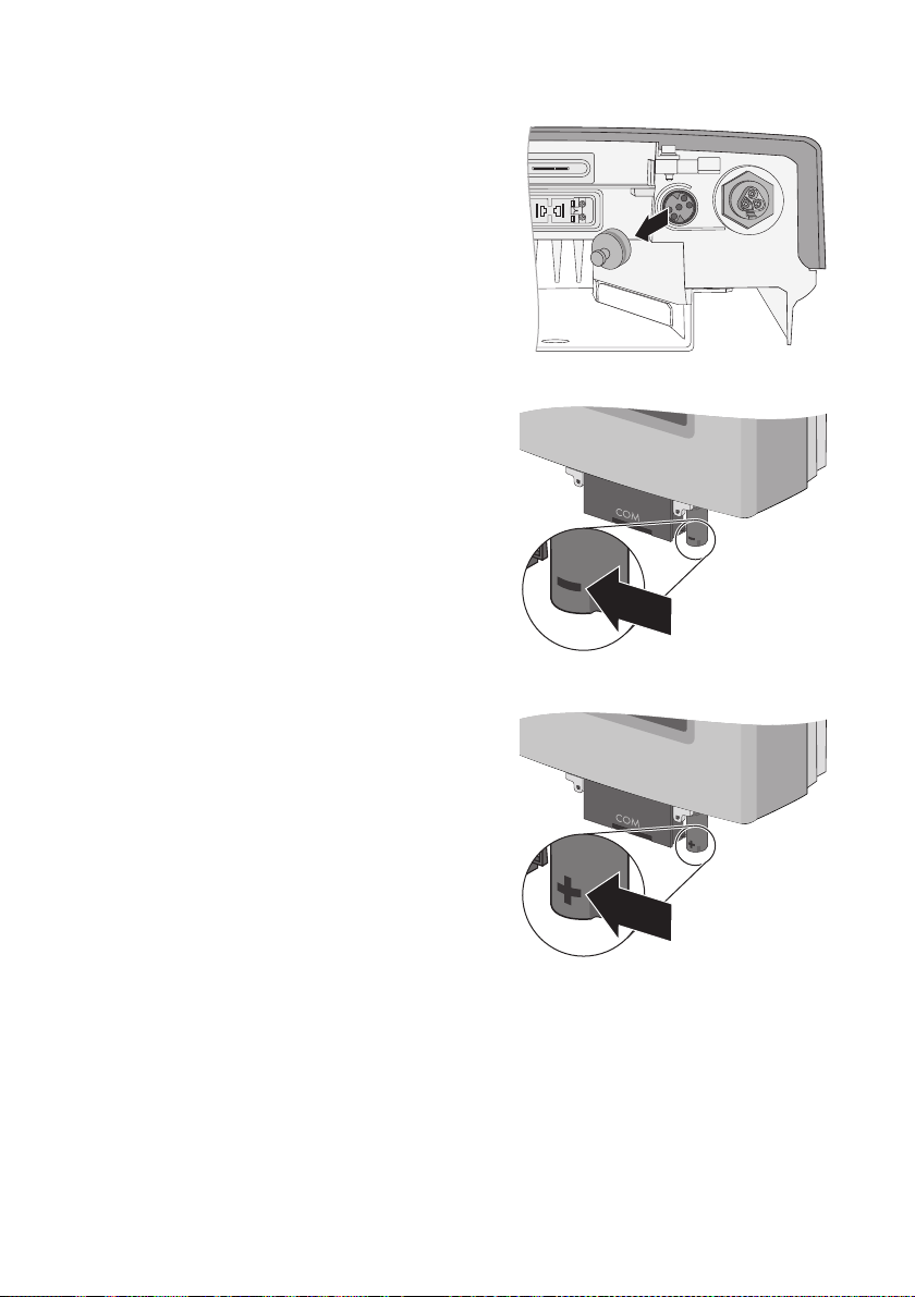
SMA Solar Technology AG Installazione di SMA Plug-in Grounding
3. Rimuovere il cappuccio di protezione dall'ingresso
sull'inverter.
4. Se si intende procedere alla messa a terra del polo
negativo dell'impianto FV:
– Applicare SMA Plug-in Grounding alla presa di
collegamento in modo che il simbolo " − " sul
cappuccio sia rivolto in avanti.
– Spingere in alto SMA Plug-in Grounding finché
non scatta in posizione.
5. Se si intende procedere alla messa a terra del polo
positivo dell'impianto FV:
– Applicare SMA Plug-in Grounding alla presa di
collegamento in modo che il simbolo "+" sul
cappuccio sia rivolto in avanti.
– Spingere in alto SMA Plug-in Grounding finché
non scatta in posizione.
☑ SMA Plug-in Grounding è installato.
Istruzioni per l’installazione Erdung_HF-IXX105020 89
Page 90
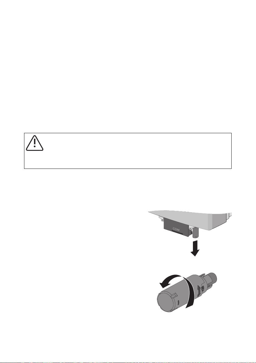
Verifica e sostituzione del fusibile di SMA Plug-in Grounding SMA Solar Technology AG
5 Verifica e sostituzione del fusibile di SMA Plug-in Grounding
Quando si verifica una dispersione verso terra nell'impianto FV, SMA Plug-in Grounding reagisce in
funzione dell'intensità della corrente di guasto:
• Il fusibile di SMA Plug-in Grounding interrompe la corrente di guasto improvvisamente
generatasi. Ciò provoca la distruzione del fusibile.
• L'inverter segnala il lento sopraggiungere di correnti di guasto (vedere capitolo 6.2”Messaggi
di errore” (Pagina95)). Eliminando tempestivamente la dispersione verso terra si previene la
distruzione del fusibile.
Dopo aver eliminato la dispersione verso terra (vedere Istruzioni per l'installazione dell'inverter),
controllare il fusibile di SMA Plug-in Grounding ed eventualmente sostituirlo. È possibile richiedere un
nuovo fusibile presso SMA Solar Technology AG (codice d'ordine KLKD-1).
AVVERTENZA!
Pericolo di incendio dovuto a fusibili non adatti!
• Ricorrere solo a fusibili del tipo Littelfuse KLKD-1, per garantire la protezione contro
il pericolo d'incendio.
Procedura
1. Disinserire l'inverter sul lato CA e CC come descritto nelle Istruzioni per l'installazione
dell'inverter.
2. Prima di sostituire il fusibile, prendere nota del tipo di messa a terra del generatore (" − " o "+").
3. Estrarre dal basso SMA Plug-in Grounding.
4. Staccare ed estrarre il cappuccio tenendo fermo
l'elemento di raccordo di SMA Plug-in Grounding.
90 Erdung_HF-IXX105020 Istruzioni per l’installazione
Page 91

SMA Solar Technology AG Verifica e sostituzione del fusibile di SMA Plug-in Grounding
5. Servendosi di una pinza, estrarre il fusibile dal
relativo supporto di SMA Plug-in Grounding.
6. Verificare lo stato del fusibile con uno strumento di
misura idoneo (controllo di continuità).
☑ Se il fusibile è difettoso, sostituirlo.
7. Se funzionante, inserire il fusibile nel relativo
supporto di SMA Plug-in Grounding, spingendolo
saldamente nel supporto.
8. Tenendo fermo l'elemento di raccordo di SMA
Plug-in Grounding, applicare il cappuccio e
stringerlo a mano.
☑ SMA Plug-in Grounding è chiuso saldamente
quando i simboli sull'elemento di raccordo e il
cappuccio formano un lucchetto.
Istruzioni per l’installazione Erdung_HF-IXX105020 91
Page 92

Verifica e sostituzione del fusibile di SMA Plug-in Grounding SMA Solar Technology AG
9. Se si intende procedere alla messa a terra del polo
negativo dell'impianto FV:
– Applicare SMA Plug-in Grounding alla presa di
collegamento in modo che il simbolo " − " sul
cappuccio sia rivolto in avanti.
– Spingere in alto SMA Plug-in Grounding finché
non scatta in posizione.
10. Se si intende procedere alla messa a terra del polo
positivo dell'impianto FV:
– Applicare SMA Plug-in Grounding alla presa di
collegamento in modo che il simbolo "+" sul
cappuccio sia rivolto in avanti.
– Spingere in alto SMA Plug-in Grounding finché
non scatta in posizione.
☑ Il fusibile di SMA Plug-in Grounding è stato sostituito.
92 Erdung_HF-IXX105020 Istruzioni per l’installazione
Page 93

SMA Solar Technology AG Parametri e messaggi di errore
6 Parametri e messaggi di errore
6.1 Parametri impostabili
Nomi di parametri in funzione del tipo di comunicazione
L'inverter utilizza un protocollo di comunicazione diverso a seconda del tipo di
comunicazione (Bluetooth o RS485) e la visualizzazione dei parametri varia:
• Comunicazione via Bluetooth e Sunny Explorer: DATA II+
• Comunicazione tramite RS485: DATA I
Per la messa a terra dell'impianto FV sono importanti 2 parametri, impostabili nell'inverter tramite un
apparecchio per la comunicazione o un PC dotato di corrispettivo software.
• Parametro "Messa a terra modulare richiesta?" (DATA II+) o "Md.GndMdt" (DATA I)
• Parametro "Tipo di messa a terra modulare richiesto" (DATA II+) o "Md.GndModReq" (DATA I)
6.1.1 Parametro "Messa a terra modulare richiesta?“ o "GndMdt"
La messa a terra del modulo può essere impostata nell'inverter tramite il parametro "Messa a terra
modulare richiesta?" o "Md.GndMdt". Osservare le impostazioni stabilite dal produttore del modulo
e le direttive in vigore sul luogo d'installazione dell'impianto FV.
Esistono 2 impostazioni:
Valore
(DATA II+ / DATA I)
No / No La normativa o il produttore del modulo non
Sì / Yes La normativa o il produttore del modulo
Istruzioni per l’installazione Erdung_HF-IXX105020 93
Significato Valore di default
(DATA II+ / DATA I)
No / No
prescrivono la messa a terra. Nonostante tale
im pos taz ion e, è pos sib ile ese gui re l a me ssa a ter ra
dell'impianto FV.
In caso di guasto a terra l'inverter non interrompe
l'immissione. L'inverter segnala un'avvertenza a
titolo informativo con codice evento "35".
prescrivono obbligatoriamente la messa a
terra. L'inverter può essere messo in funzione solo
con SMA Plug-in Grounding.
In caso di guasto a terra l'inverter interrompe
l'immissione in rete e passa al blocco di
funzionamento. L'inverter segnala un errore di
isolamento con codice evento "35".
Page 94

Parametri e messaggi di errore SMA Solar Technology AG
6.1.2 Parametro "Tipo di messa a terra modulare richiesto" o
"Md.GndModReq"
Tramite il parametro "Tipo di messa a terra modulare richiesto" o "Md.GndModReq" è possibile
stabilire il tipo di messa a terra desiderato. Questo parametro è impostato in fabbrica su
"Inapprendimento" o "GndModLrn".
Questo parametro può essere impostato in 2 modi:
• Automatica: nella modalità di apprendimento, l'inverter memorizza automaticamente, dopo
10 ore di esercizio, il tipo di messa a terra di SMA Plug-in Grounding inserito.
• Manuale: è possibile modificare il tipo di messa terra desiderato via comunicazione
(Bluetooth/RS485), dopo aver messo il funzione l'inverter. L'impostazione manuale del
parametro è possibile anche senza SMA Plug-in Grounding.
Esistono 4 impostazioni:
Valore
(DATA II+ / DATA I)
Positivo / GndModPs L'inverter consente solo la messa a terra positiva. In apprendimento /
Negativo / GndModNg L'inverter consente solo la messa a terra negativa.
Nessuna richiesta /
GndModNoneReq
In apprendimento /
GndModLrn
Significato Valore di default
(DATA II+ / DATA I)
GndModLrn
Non è prescritto alcun tipo di messa a terra.
L'inverter può essere messo in funzione con o
senza messa a terra.
L'inverter sorveglia la messa a terra e memorizza
dopo 10 ore di esercizio il tipo di messa a terra
con SMA Plug-in Grounding inserito.
L'inverter può essere messo in funzione con o
senza messa a terra.
94 Erdung_HF-IXX105020 Istruzioni per l’installazione
Page 95

SMA Solar Technology AG Parametri e messaggi di errore
6.2 Messaggi di errore
Eliminare sempre l'errore
Eliminare immediatamente gli errori, anche se l'inverter non interrompe l'immissione in rete.
L'inverter si comporta differentemente, a seconda dell'impostazione del parametro "Messa a terra
modulare richiesta?“ o "Md.GndMdt".
Possono essere segnalati i seguenti messaggi di errore:
Parametro "Messa a terra modulare richiesta?“ / "Md.GndMdt"
Impostazione: Sì / Yes Causa / Soluzione
• Codice evento 35
• Messaggio sul display
<Guasto fusibile di terra - Contr. fus. terra >
• LED rosso acceso.
• LED verde lampeggiante o spento.
• L'inverter non immette in rete.
• Codice evento 35
• Messaggio sul display
< Res. di isolamento - Contr. generatore >
• LED rosso acceso.
• LED verde lampeggiante o spento.
• L'inverter non immette in rete.
• Codice evento 42
• Messaggio sul display
< Tip. terra err., contr. set terra >
• LED rosso acceso.
• LED verde lampeggiante o spento.
• L'inverter non immette in rete.
Si è verificata una sovracorrente.
• Eliminare l'errore come descritto
nel capitolo 6.3.2”Eliminazione di
guasto al fusibile di terra”
(Pagina97).
Si è verificato un errore di isolamento.
• Se è installato SMA Plug-in
Grounding, eliminare l'errore
come descritto nel capitolo
6.3.3”Eliminazione dell'errore di
isolamento” (Pagina98).
• Se SMA Plug-in Grounding non è
installato, procedere al
collegamento di SMA Plug-in
Grounding come descritto nel
capitolo 4”Installazione di SMA
Plug-in Grounding” (Pagina88).
Manca SMA Plug-in Grounding o ne è
stata invertita la polarità.
• Eliminare l'errore come descritto
nel capitolo 6.3.4”Rettifica del
tipo di messa a terra” (Pagina98).
Istruzioni per l’installazione Erdung_HF-IXX105020 95
Page 96

Parametri e messaggi di errore SMA Solar Technology AG
Parametro "Messa a terra modulare richiesta?“ / "Md.GndMdt"
Impostazione: No / No Causa / Soluzione
• Codice evento 35
• Messaggio sul display
< Res. di isolamento - Contr. generatore >
• LED rosso acceso.
• LED verde acceso.
• L'inverter immette in rete.
• Codice evento 35
• Messaggio sul display
< Res. di isolamento - Contr. generatore >
• LED rosso acceso.
• LED verde acceso.
• L'inverter immette in rete.
• Codice evento 42
• Messaggio sul display
< Tip. terra err., contr. set terra >
• LED rosso acceso.
• LED verde acceso.
• L'inverter immette in rete.
Si è verificata una sovracorrente.
• Eliminare l'errore come descritto
nel capitolo 6.3.3”Eliminazione
dell'errore di isolamento”
(Pagina98).
Si è verificato un errore di isolamento.
• Eliminare l'errore come descritto
nel capitolo 6.3.3”Eliminazione
dell'errore di isolamento”
(Pagina98).
Manca SMA Plug-in Grounding o ne è
stata invertita la polarità.
• Eliminare l'errore come descritto
nel capitolo 6.3.4”Rettifica del
tipo di messa a terra” (Pagina98).
96 Erdung_HF-IXX105020 Istruzioni per l’installazione
Page 97

SMA Solar Technology AG Parametri e messaggi di errore
6.3 Eliminazione di errori
6.3.1 Sicurezza
PERICOLO!
Pericolo di morte per scossa elettrica!
L'inverter funziona in alta tensione.
• D isi nse rir e l' inv ert er s ul l ato CA e CC c ome des cri tto nel le I struzioni per l'installazione
dell'inverter.
6.3.2 Eliminazione di guasto al fusibile di terra
Per eliminare l'errore < Guasto fusibile di terra - Contr. fus. terra > procedere come segue:
1. Disinserire l'inverter sul lato CA e CC come descritto nelle Istruzioni per l'installazione
dell'inverter.
2. Prendere nota del tipo di messa a terra del generatore (" − " o "+") ed estrarre al basso
SMA Plug-in Grounding.
3. Verificare sul generatore FV la presenza di dispersione verso terra, come descritto nelle
Istruzioni per l'installazione dell'inverter e, in tal caso, eliminarla.
4. Rimettere in funzione l'inverter senza SMA Plug-in Grounding, come descritto nelle Istruzioni
per l'installazione dell'inverter.
☑ L'inverter verifica la presenza di dispersione verso terra.
– Se non viene più riscontrata dispersione verso terra, il messaggio di errore < Guasto
fusibile di terra > passa a < Res. di isolamento > appena la tensione di avvio raggiunge
i 220 V.
– Se si continua a riscontrare dispersione verso terra, resta invariato il messaggio di errore
< Guasto fusibile di terra >. In questo caso ripetere le operazioni ai punti 3 e 4.
5. Disinserire l'inverter sul lato CA e CC come descritto nelle Istruzioni per l'installazione
dell'inverter.
6. Verificare il fusibile di SMA Plug-in Grounding ed eventualmente sostituirlo come descritto nel
capitolo 5”Verifica e sostituzione del fusibile di SMA Plug-in Grounding” (Pagina90).
7. Se funzionante, collegare SMA Plug-in Grounding all'inverter come descritto nel capitolo
4”Installazione di SMA Plug-in Grounding” (Pagina88).
8. Rimettere in funzione l'inverter, come descritto nelle Istruzioni per l'installazione dell'inverter.
L'inverter verifica se il tipo di messa a terra impostato coincide con il tipo di messa a terra di
SMA Plug-in Grounding installato.
☑ Una volta rimesso in funzione, l'inverter riprende l'immissione in rete.
Istruzioni per l’installazione Erdung_HF-IXX105020 97
Page 98

Parametri e messaggi di errore SMA Solar Technology AG
6.3.3 Eliminazione dell'errore di isolamento
Per eliminare l'errore < Res. di isolamento - Contr. generatore > procedere come segue:
1. Disinserire l'inverter sul lato CA e CC come descritto nelle Istruzioni per l'installazione
dell'inverter.
2. Se è collegato SMA Plug-in Grounding, prendere nota del tipo di messa a terra del generatore
(" − " o "+") ed estrarre al basso SMA Plug-in Grounding.
3. Verificare sul generatore FV la presenza di dispersione verso terra, come descritto nelle
Istruzioni per l'installazione dell'inverter e, se necessario, eliminarla.
4. Verificare il fusibile di SMA Plug-in Grounding ed eventualmente sostituirlo come descritto nel
capitolo 5”Verifica e sostituzione del fusibile di SMA Plug-in Grounding” (Pagina90).
5. Se funzionante, collegare SMA Plug-in Grounding all'inverter come descritto nel
capitolo4”Installazione di SMA Plug-in Grounding” (Pagina88).
6. Rimettere in funzione l'inverter, come descritto nelle Istruzioni per l'installazione dell'inverter.
☑ L'inverter verifica la presenza di dispersione verso terra e se i l ti po d i me ssa a te rra imp ost ato
coincide con il tipo di messa a terra di SMA Plug-in Grounding installato.
– Se si continua a riscontrare dispersione verso terra, resta invariato il messaggio di errore
< Res. di isolamento - Contr. generatore >. In questo caso ripetere le operazioni ai
punti3 e 6.
– Se non viene più riscontrata dispersione verso terra, si spegne il messaggio di errore
<Res. di isolamento - Contr. generatore > e l'inverter riprende l'immissione in rete.
– Se è richiesta una messa a terra positiva o negativa e SMA Plug-in Grounding è stato
collegato con una polarità errata, appare il messaggio di errore <Tip. terra err., contr.
set terra >. Proseguire come descritto nel caoitolo 6.3.4”Rettifica del tipo di messa a
terra” (Pagina98).
☑ Una volta rimesso in funzione, l'inverter riprende l'immissione in rete.
6.3.4 Rettifica del tipo di messa a terra
Per eliminare l'errore < Tip. terra err., contr. set terra > procedere come segue:
1. Disinserire l'inverter sul lato CA e CC come descritto nelle Istruzioni per l'installazione
dell'inverter.
2. Se funzionante, collegare SMA Plug-in Grounding con la corretta polarità all'inverter, come
descritto nel capitolo 4”Installazione di SMA Plug-in Grounding” (Pagina88).
3. Rimettere in funzione l'inverter, come descritto nelle Istruzioni per l'installazione dell'inverter.
L'inverter verifica se il tipo di messa a terra coincide con il tipo di messa a terra impostato o
appreso.
☑ L'errore è eliminato e l'inverter riprende l'immissione in rete.
98 Erdung_HF-IXX105020 Istruzioni per l’installazione
Page 99

SMA Solar Technology AG Contatto
7 Contatto
In caso di problemi tecnici con i nostri prodotti si prega di rivolgersi al Servizio assistenza tecnica
SMA. Per poter essere d'aiuto, necessitiamo dei seguenti dati:
•Tipo di inverter
• Numero di serie dell'inverter
• Tipo e numero dei moduli FV collegati
• Tipo della messa a terra (positiva o negativa)
• Codice evento o messaggio sul display dell'inverter
• Dotazioni opzionali, per es. apparecchi per la comunicazione
•Eventualmente tipo del relè multifunzione collegato
SMA Italia S.r.l.
Milano Business Park
Via dei Missaglia 97
20141 Milano
Tel. +39 02 89347 299
Fax +39 02 89347 201
Service@SMA-Italia.com
www.SMA-Italia.com
Istruzioni per l’installazione Erdung_HF-IXX105020 99
Page 100

Indice SMA Solar Technology AG
Le informazioni contenute in questa documentazione sono proprietà della SMA Solar Technology AG. Per la pubblicazione,
integrale o parziale, è necessario il consenso scritto della SMA Solar Technology AG. La riproduzione per scopi interni
all'azienda, destinata alla valutazione del prodotto o al suo utilizzo corretto, è consentita e non è soggetta ad approvazione.
Esonero di responsabilità
Come principio valgono le Condizioni Generali di Fornitura della SMA Solar Technology AG.
Il contenuto della presente documentazione viene verificato di continuo e se necessario adattato. Non possono tuttavia essere
escluse divergenze. Non può essere data alcuna garanzia di completezza. La versione aggiornata è richiamabile in Internet sul
sito www.SMA.de oppure può essere ordinata attraverso i normali canali di distribuzione.
Sono escluse rivendicazioni di garanzia e di responsabilità in caso di danni di ogni genere qualora gli stessi siano riconducibili
ad una o ad alcune delle seguenti cause:
• danni dovuti al trasporto,
• utilizzo improprio del prodotto oppure non conforme alla sua destinazione,
• impiego del prodotto in un ambiente non previsto,
• impiego del prodotto senza tener conto delle norme di sicurezza legali rilevanti nel luogo d'impiego,
• mancata osservanza delle indicazioni di avvertimento e di sicurezza riportate in tutte le documentazioni essenziali per il
prodotto,
• impiego del prodotto in condizioni di sicurezza e di protezione errate,
• modifica o riparazione arbitraria del prodotto e del software fornito,
• funzionamento errato del prodotto dovuto all'azione di apparecchi collegati o adiacenti al di fuori dei valori limite ammessi
per legge,
• catastrofi e forza maggiore.
L'utilizzo del software in dotazione prodotto dalla SMA Solar Technology AG è sottoposto inoltre alle seguenti condizioni:
• La SMA Solar Technology AG non si assume alcuna responsabilità per danni diretti o indiretti determinati dall'impiego del
software prodotto dalla SMA Solar Technology AG, ciò si applica anche alla prestazione o non-prestazione di attività di
assistenza.
• Il software fornito che non sia stato prodotto dalla SMA Solar Technology AG è soggetto ai relativi accordi di licenza e di
responsabilità del produttore.
Garanzia di fabbrica SMA
Le attuali condizioni di garanzia sono allegate al vostro apparecchio. In caso di necessità, è possibile scaricarle dal sito Internet
www.SMA.de o ottenerle in formato cartaceo attraverso i normali canali di distribuzione.
Marchio
Tutti i marchi sono validi anche se gli stessi non sono contrassegnati separatamente. L'assenza di contrassegno non significa che
un prodotto o un marchio non siano registrati.
Il marchio e il logo Bluetooth
Technology AG è autorizzato con licenza.
SMA Solar Technology AG
Sonnenallee 1
34266 Niestetal
Germania
Tel. +49 561 9522-0
Fax +49 561 9522-100
www.SMA.de
E-Mail: info@SMA.de
© 2004-2010 SMA Solar Technology AG. Tutti i diritti riservati.
®
sono marchi registrati di proprietà di Bluetooth SIG, Inc.; il loro utilizzo da parte della SMA Solar
100 Erdung_HF-IXX105020 Istruzioni per l’installazione
 Loading...