

Page 1
Installation Manual
SMA INVERTER MANAGER /
SMA DIGITAL I/O BOX
1 Information on this Document
1.1 Validity
This document is valid for the SMA Inverter Manager and
for the SMA Digital I/O Box.
1.2 Target Group
The activities described in this document must only be
performed by qualified persons. Qualified persons must
have the following skills:
• Training in the installation and commissioning of
electrical devices
• Training in how to deal with the dangers and risks
associated with installing and using electrical devices
and installations
• Training in the installation and configuration of IT
systems
• Knowledge of how an inverter works and is operated
• Knowledge of all applicable laws, standards and
directives
• Knowledge of and compliance with this document and
all safety information and warning messages
1.3 Symbols
Symbol Explanation
Indicates a hazardous situation
which, if not avoided, will result
in death or serious injury
Indicates a hazardous situation
which, if not avoided, can result
in death or serious injury
Indicates a hazardous situation
which, if not avoided, can result
in minor or moderate injury
Indicates a situation which, if
not avoided, can result in
property damage
Symbol Explanation
Information that is important for
a specific topic or goal, but is
not safety-relevant
☐ Indicates a requirement for
meeting a specific goal
☑ Desired result
✖ A problem that might occur
1.4 Nomenclature
Complete designation Designation in this
document
SMA Inverter Manager Inverter Manager
SMA Digital I/O Box I/O Box
SMA Solar Technology AG SMA
SMA America, LLC
SMA Solar Technology
Canada Inc.
IMVIOBOX-IA-xx-10 | 139R0136 | Version 1.0 ENGLISH
Page 2

2 Safety SMA Solar Technology AG / SMA America, LLC
2Safety
2.1 Intended Use
The Inverter Manager is a device for monitoring and
controlling up to 42 SMA inverters of the type STP 60-10
and STP 60-US-10 in decentralized PV systems and
large-scale PV power plants with up to 2.5 MW power.
The I/O Box is a multi-function interface for one
Inverter Manager. The I/O Box receives commands for grid
management services via digital signals and sends these
specifications to the Inverter Manager.
The Inverter Manager receives the specifications from the
I/O Box and controls all inverters in the system accordingly.
The Inverter Manager and the I/O Box must only be used
indoors and must only be operated with the SMA inverter
Sunny Tripower 60 (STP 60-10 and STP 60-US-10).
Use this product only in accordance with the information
provided in the enclosed documentation and with the
locally applicable standards and directives. Any other
application may cause personal injury or property damage.
For safety reasons, it is not permitted to modify the product
or install components that are not explicitly recommended
or distributed by SMA for the product. Unauthorized
changes or modifications will void all warranty claims and
the operating license. Any use of the product other than that
described in the Intended Use section does not qualify as
appropriate.
The type label must remain permanently attached to the
product. The enclosed documentation is an integral part of
this product.
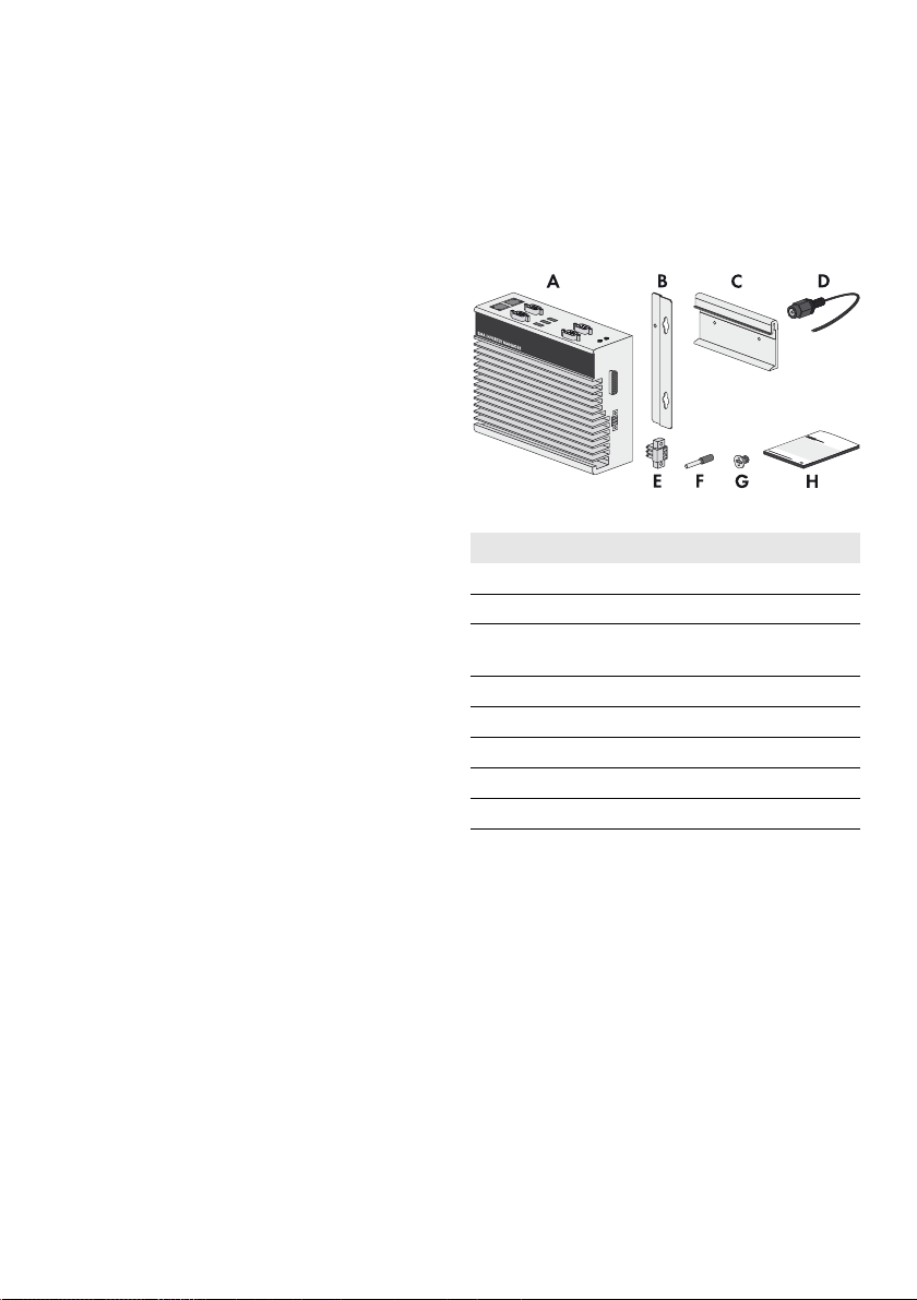
3 Inverter Manager
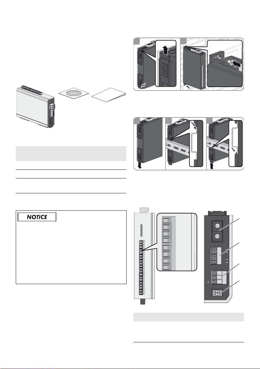
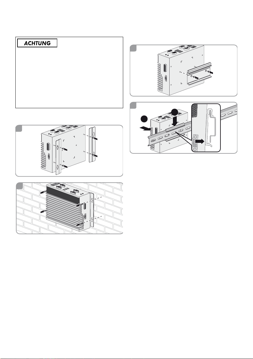
3.1 Scope of Delivery
Check the scope of delivery of each product for
completeness and any externally visible damage. Contact
your distributor if the scope of delivery is incomplete or
damaged.
Figure1: Components included in the scope of delivery of the
Inverter Manager
Position QuantityDesignation
A1InverterManager
B 2 Wall mounting bracket
C 1 Bracket for mounting on top-hat rail
(35 mm DIN rail)
D 1 Connection for electricity supply
E 1 Connecting terminal plate for
F 2 Bootlace ferrules
G 2 Screw for wall mounting
H 1 Installation manual
electricity supply
2 IMVIOBOX-IA-xx-10 Installation Manual
Page 3

SMA Solar Technology AG / SMA America, LLC 3 Inverter Manager
1
SM
A IN
VER
TER M
AN
AGER
2
1
2
1
2
3.2 Mounting the Inverter Manager
Damage to the products and cables due to moisture
The Inverter Manager and the I/O Box are not protected
against splash water. Consequently, moisture can
penetrate the device and damage the products and
cables.
• The Inverter Manager and the I/O Box must be
installed in a dry environment, e.g. indoors or in a
sp las h-p roo f en clo sur e (d egr ee o f pr ote cti on: at l eas t
IP54 (NEMA 3R)).
3.2.1 Option 1: Wall Mounting
3.2.2 Option 2: Mounting on Top-Hat Rail
Installation Manual IMVIOBOX-IA-xx-10 3
Page 4
3 Inverter Manager SMA Solar Technology AG / SMA America, LLC
3.3 Connection to the Inverter Manager
3.3.1 Safety Information
Danger to life due to electric shock
Lethal voltages are present at the connection point of the
utility grid.
• Disconnect the connection point from voltage sources
and ensure that the connection point is voltage-free.
3.3.2 Circuitry Overview
Position Designation
A Sunny Tripower 60
B PC with LCS tool
CRouter/DHCP
4 IMVIOBOX-IA-xx-10 Installation Manual
Position Designation
D SunSpec Alliance compatible weather
station (optional)
E Inverter Manager
FI/OBox (optional)
Page 5
SMA Solar Technology AG / SMA America, LLC 3 Inverter Manager
81
81
32145
9876
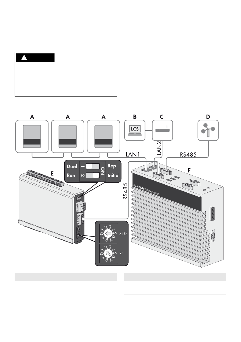
3.3.3 Connecting the Inverter and Router via Ethernet
Pin assignment of network ports (LAN1 and LAN2):
Pin Assignment for
10/100 Mbps
1 ETx+ TRD(0)+
2 ETx- TRD(0)3 ERx+ TRD(1)+
4--- TRD(2)+
5--- TRD(2)6 ERx- TRD(1)7--- TRD(3)+
8--- TRD(3)-
Assignment for
1,000 Mbps
3.3.4 Connecting the I/O Box and Weather Station (Optional)
Pin assignment of the serial interface (RS485):
Pin Assignment
8 ---
3.3.5 Connecting the Inverter Manager to the Voltage Supply
Danger to life due to electric shock from touching
an ungrounded product
Touching an ungrounded product can cause a lethal
electric shock.
• Ensure that the product is integrated in the existing
overvoltage protection.
• Ground the enclosure of the product.
Procedure:
To connect the Inverter Manager to the voltage supply,
perform the following actions in the specified order.
• Connect the grounding conductor to the
Inverter Manager.
• Connect the power supply unit.
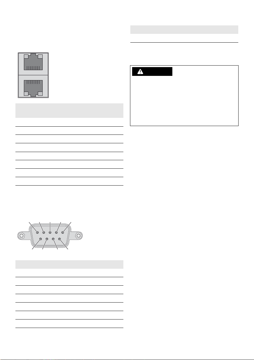
Connecting the Grounding Conductor to the
Inverter Manager
Shielded ground: The shielded ground (also called
"protected ground") is located at the pin connector for the
electrical connection in the displayed view.
Procedure:
• Ground the Inverter Manager. For this purpose,
connect the grounding conductor to the grounding
screw of the Inverter Manager. Proper grounding and
the correct cable route help limit possible interference
emissions due to electromagnetic interferences (EMI).
Pin Assignment
1 --2 --3 DataB(+)
4 DataA(-)
5GND
6 --7 ---
Installation Manual IMVIOBOX-IA-xx-10 5
Page 6
3 Inverter Manager SMA Solar Technology AG / SMA America, LLC
Connecting the Power Supply Unit
SMA recommends using the top-hat rail power supply
available as an accessory (order number:
CLCON-PWRSUPPLY).
Procedure:
1. Mount the power supply unit (see manual from
manufacturer).
2. Connect the connection cable to the power supply unit
(see manual from manufacturer). Trim the unneeded
insulated conductors up to the cable sheath and note
down the conductor colors.
3. Connect the connection cable to the connecting
terminal plate for the voltage supply (9 VDC to
36 VDC). Make sure that the shielded grounding
conductor is connected with the grounding terminal.
4. Plug the connecting terminal plate for the voltage
supply with connected power supply unit in the pin
connector "Power Input" of the Inverter Manager.
5. Connect the AC connection cable to the power supply
unit (see the manual from manufacturer).
6.
Danger to life due to electric shock
Lethal voltages are present at the connection point of
the utility grid.
• Disconnect the connection point from voltage
sources and make sure it cannot be
reconnected.
7. Connect the other end of the AC connection cable to
the voltage supply.
8. Connect the connection point to the utility grid.
☑ Once the Power LED is glowing green, the
Inverter Manager is ready for operation.
Real-Time Clock
The real-time clock of the Inverter Manager is powered by
a lithium battery. We strongly recommend not to change the
lithium battery without the assistance of qualified service
personnel. Should it become necessary to replace the
battery, contact the Service (for contact information see
www.SMA-Solar.com).
Wh en t he b att ery is r epl ace d wi th t he w ron g ba tte ry t ype ,
there is a risk of explosion.
3.4 Setting Up the Ethernet Connection of the Inverter Manager
The factory default settings for the LANs of the
Inverter Manager can be found below.
IP address Subnet mask
LAN1 192.168.4.127 255.255.255.0
LAN2 is assigned via
DHCP
is assigned via
DHCP
3.5 LED Signals of the Inverter Manager
LED Status Explanation
Power Glowing
green
Off The Inverter Manager is not
LAN Glowing
Tx1, Tx2
(P1-P2)
Rx1, Rx2
(P1-P2)
green
Glowing
yellow
Off No activity or 10 Mbps
Flashing
green
Off No data transmission via
Flashing
green
Off No data reception via serial
The Inverter Manager is in
operation.
in operation.
100 Mbps Ethernet mode
1,000 Mbps (gigabyte)
Ethernet mode
Ethernet
Data transmission via serial
ports P1-P2
serial ports P1-P2
Data reception via serial
ports P1-P2
ports P1-P2
6 IMVIOBOX-IA-xx-10 Installation Manual
Page 7

SMA Solar Technology AG / SMA America, LLC 3 Inverter Manager
3.6 Technical Data
Voltage Supply
Input voltage 9 VDC to 36 VDC
Power consumption < 20 W
Maximum conductor
cross-section
General Data
Dimensions (width x height
x depth)
Weight 940 g (2 lbs)
Mounting type Wall mounting or top-hat
Operating temperature
range
Relative humidity,
non-condensing
Approvals UL 508, UL 60950-1, CSA
1.3 mm² (16 AWG)
160 mm x 125 mm x
49 mm
(6.3 in x 4.9 in x 1.9 in)
rail
-40°C to +85°C
(-40°F to +185°F)
5% to 95%
C22.2 No. 60950-1-07,
EN 60950-1, CCC
(GB9254, GB17625.1),
EN 55022, Class A, EN
61000-3-2, Class D, EN
61000-3-3, EN 55024,
FCC Part 15, Subpart B,
Class A
Interfaces
Maximum cable length for
RS485 cabling
System monitoring Sunny Portal, SunSpec
Active/reactive power
setpoint
Power Supply Unit
Model number CLCON-PWRSUPPLY
Input 100 V AC to 240 V AC
Output 24 VDC / 2.5 A
Ambient temperature ‒25°C to +70°C
Approvals CE, UL
1,200 m (4,000 ft)
Modbus TCP
Constant value, curve or
remotely controlled via
SunSpec Modbus TCP /
SMA Digital I/O Box
Interfaces
User interface LCS tool for PC via Ethernet
Interface to inverter LAN1, Ethernet interface
Interface to external
network
Interface to SMA Digital I/
OBox
Sensor interface for
SunSpec compatible
weather stations (optional)
Maximum cable length for
Ethernet connection
Installation Manual IMVIOBOX-IA-xx-10 7
(RJ45)
LAN2, Ethernet interface
(RJ45)
SunSpec mode, RS485
(D-Sub 9)
SunSpec mode, RS485
(D-Sub 9)
100 m (328 ft)
Page 8
4 SMA Digital I/O Box SMA Solar Technology AG / SMA America, LLC
A
BC
1
2
1
2
3
1
2
3
4
5
6
7
8
9
0
1
2
3
4
5
6
7
8
9
0
1
2
3
4
5
6
7
8
9
0
1
2
3
4
5
6
7
8
9
0
D1+
D1-
GND
D2+
D2-
P1
P2
V+
V-
X10
X1
Dual
Run
Rep
Initial
COM0
DI0
DI1
DI2
DI3
DI4
DI5
DI6
DI7
COM1
DIO0
DIO1
DIO2
DIO3
GND
DIO4
DIO5
DIO6
DIO7
GND
A
C
D
COM0
DI0
DI1
DI2
DI3
DI4
DI5
GND
B
E
4 SMA Digital I/O Box
4.1 Scope of Delivery
Check the scope of delivery of each product for
completeness and any externally visible damage. Contact
your distributor if the scope of delivery is incomplete or
damaged.
Figure2: Components included in the scope of delivery of the SMA
Digital I/O Box
Position QuantityDesignation
A1SMA Digital I/OBox
B1CD
C 1 Quick reference guide for
4.2 Mounting the I/O Box
installation
4.2.1 Option 1: Wall Mounting
4.2.2 Option 2: Mounting on Top-Hat Rail
4.3 Connection to the I/O Box
4.3.1 Overview
Damage to the products and cables due to moisture
The Inverter Manager and the I/O Box are not protected
against splash water. Consequently, moisture can
penetrate the device and damage the products and
cables.
• The Inverter Manager and the I/O Box must be
installed in a dry environment, e.g. indoors or in a
sp las h-p roo f en clo sur e (d egr ee o f pr ote cti on: at l eas t
IP54 (NEMA 3R)).
8 IMVIOBOX-IA-xx-10 Installation Manual
Position Designation
A Digital inputs for connecting a signal source
(inputs DI0 to DI5 can be assigned; all
other inputs have no function)
Page 9
SMA Solar Technology AG / SMA America, LLC 4 SMA Digital I/O Box
5 GND
3 Data B (+)
4 Data A (−)
COM0
DI0
DI1
DI2
DI3
DI4
DI5
DI6
DI7
COM1
DIO0
DIO1
DIO2
DIO3
GND
DIO4
DIO5
DIO6
DIO7
GND
COM0
DI0
DI1
DI2
DI3
DI4
DI5
GND
Dry Contact:
closed: DI0 = off
open: DI0 = on
COM0
DI0
DI1
DI2
DI3
DI4
DI5
DI6
DI7
COM1
DIO0
DIO1
DIO2
DIO3
GND
DIO4
DIO5
DIO6
DIO7
GND
COM0
DI0
DI1
DI2
DI3
DI4
DI5
GND
Wet Contact:
0 V ... 3 V = off
10 V ... 30 V = on
U
U
10 V ... 30 V
V-
V+
Position Designation
B Maintain the default setting: X1 = 1, X10 =
0
C Connection of the Inverter Manager
D Connection of the electricity supply
E Maintain the default setting: 1 = Dual, 2 =
Initial
4.3.2 Connecting the Inverter Manager
Pin assignment of the terminal (RS485):
Pin Assignment
D1+ --D1- --GND GND
D2+ DataA(+)
D2- DataB(-)
4.3.3 Connecting the Signal Source
Connection of a Signal Source with
Potential-Free Relay Contact
Connection of a Signal Source (10 V to 30 V)
with Digital Output Signals
4.3.4 Connecting the I/O Box to the Voltage Supply
Connect the 12 to 36 V DC connection cable to the terminal
for the voltage supply. Connect the grounding of the
connection cable to the "V-" terminal and connect the
grounding pin if grounding is present.
Pin Assignment
V- Voltage Supply
V+ +24 VDC Nominal (+12 VDC to 36 VDC)
Diameter of the leads
For safety reasons, the leads for the electricity
supply must have a diameter of at least 2 mm².
Installation Manual IMVIOBOX-IA-xx-10 9
Page 10

4 SMA Digital I/O Box SMA Solar Technology AG / SMA America, LLC
4.3.5 LED Signals of the I/O Box
LED Status Explanation
Power Glowing
yellow
Of f T he I/O Box is not in operati on.
Ready Glowing
green
Flashing
green once
per second
Flashing
green every
0.5 seconds
Flashing
green
Off The system is not ready for
Port 1 Flashing
green
Port 2 Flashing
yellow
The I/O Box is in operation.
The system is ready for
operation.
The "detect" function was
tripped.
Firmware is being updated.
Wh en t he g ree n LE D is glo win g
for five seconds and then goes
off for five seconds, it means
that the system is in "Safe
Mode".
operation.
Data is being sent or received.
Data is being sent or received.
System Data
Operating altitude 2,000 m
Standards and
certifications
Warranty 5 years
Digital Input
Sensor type Potential-free contact (NPN
I/O mode DI or event counter
Potential-free contact On = ground fault
Wet contact (DI to COM) On = 10 VDC to 30 VDC
Insulation voltage 3,000 VDC or 2,000 Veff
Counter/Frequency 250 Hz, memory in off-state
UL 508, CE, FCC Class A
or PNP); wet contact
Off = open
Off = 0 VDC to 3 VDC
4.4 Technical Data
System Data
Electricity supply 24 VDC nominal,
12 VDC to 36 VDC
Cabling I/O cable max. 4 AWG
Dimensions 27.8 mm x 124 mm x 84
mm (1.09 in x 4.88 in x
3.31 in)
Weight < 200 g
Operating temperature
range
Storage temperature -40°C to +85°C
Relative humidity,
non-condensing
10 IMVIOBOX-IA-xx-10 Installation Manual
Standard module:
-10°C to +60°C
(14°F to 140°F)
(-40°F to 185°F)
5% to 95%
Page 11
(&'")3
Installationsanleitung
SMA INVERTER MANAGER /
SMA DIGITAL I/O BOX
1 Hinweise zu diesem
Dokument
1.1Gültigkeitsbereich
Dieses Dokument gilt für den SMA Inverter Manager und
die SMA Digital I/O Box.
1.2Zielgruppe
Die in diesem Dokument beschriebenen Tätigkeiten dürfen
nur Fachkräfte durchführen. Die Fachkräfte müssen über
folgende Qualifikation verfügen:
• Ausbildung für die Installation und Inbetriebnahme von
elektrischen Geräten
• S chu lun g im Umg ang mit Gef ahr en un d Ri sik en b ei d er
Installation und Bedienung elektrischer Geräte und
Anlagen
• Ausbildung für die Installation und Konfiguration von
IT-Systemen
• Kenntnis über Funktionsweise und Betrieb eines
Wechselrichters
• Kenntnis der einschlägigen Gesetze, Normen und
Richtlinien
• Kenntnis und Beachtung dieses Dokuments mit allen
Sicherheits- und Warnhinweisen
1.3Symbole
Symbol Erklärung
Warnhinweis, dessen
Nichtbeachtung unmittelbar
zum Tod oder zu schwerer
Verletzung führt
Warnhinweis, dessen
Nichtbeachtung zum Tod oder
zu schwerer Verletzung führen
kann
Warnhinweis, dessen
Nichtbeachtung zu einer
leichten oder mittleren
Verletzung führen kann
Symbol Erklärung
Warnhinweis, dessen
Nichtbeachtung zu
Sachschäden führen kann
Information, die für ein
bestimmtes Thema oder Ziel
wichtig, aber nicht
sicherheitsrelevant ist
☐ Voraussetzung, die für ein
bestimmtes Ziel gegeben sein
muss
☑ Erwünschtes Ergebnis
✖ Möglicherweise auftretendes
Problem
1.4Nomenklatur
Vollständige Benennung Benennung in diesem
Dokument
SMA Inverter Manager Inverter Manager
SMA Digital I/O Box I/O Box
SMA Solar Technology AG SMA
SMA America, LLC
SMA Solar Technology
Canada Inc.
IMVIOBOX-de-10 | Version 1.0 DEUTSCH
Page 12
2 Sicherheit SMA Solar Technology AG / SMA America, LLC
2Sicherheit
2.1Bestimmungsgemäße
Verwendung
Der Inverter Manager ist ein Gerät zur Überwachung und
Steuerung von bis zu 42 SMA Wechselrichtern vom Typ
STP 60-10 und STP 60-US-10 in dezentralen PV-Anlagen
und PV-Großanlagen mit einer Leistung bis 2,5 MW.
Die I/O Box ist eine Multifunktionsschnittstelle für 1 Inverter
Manager. Die I/O Box empfängt Befehle für die
Netzsystemdienstleistungen über digitale Signale und
sendet die Vorgaben an den Inverter Manager.
Der Inverter Manager empfängt die Vorgaben von der
I/O Box und steuert entsprechend alle Wechselrichter in
der Anlage. Der Inverter Manager und die I/O Box dürfen
nur im Innenbereich eingesetzt und ausschließlich mit dem
SMA Wechselrichter Sunny Tripower 60 (STP 60-10 und
STP 60-US-10) betrieben werden.
Setzen Sie das Produkt ausschließlich nach den Angaben
der beigefügten Dokumentationen und gemäß den vor Ort
gültigen Normen und Richtlinien ein. Ein anderer Einsatz
kann zu Personen- oder Sachschäden führen. Aus
Sicherheitsgründen ist es untersagt, das Produkt zu
verändern oder Bauteile einzubauen, die nicht ausdrücklich
von SMA für das Produkt empfohlen oder vertrieben
werden. Unerlaubte Veränderungen oder Umbauten lassen
die Gewährleistungsansprüche und die Betriebserlaubnis
er lös che n. J ede and ere Ver wen dun g de s Pr odu kts als in d er
bestimmungsgemäßen Verwendung beschrieben gilt als
nicht bestimmungsgemäß.
Das Typenschild muss dauerhaft am Produkt angebracht
sein. Die beigefügten Dokumentationen sind Bestandteil des
Produkts.
3Inverter Manager
3.1Lieferumfang
Prüfen Sie den Lieferumfang jedes Produkts auf
Vollständigkeit und äußerlich sichtbare Beschädigungen.
Setzen Sie sich bei unvollständigem Lieferumfang oder
Beschädigungen mit Ihrem Fachhändler in Verbindung.
Abbildung1:Bestandteile des Lieferumfangs des Inverter Managers
Position Anzahl Bezeichnung
A 1 Inverter Manager
B 2 Halterung für Wandmontage
C 1 Halterung für Montage auf
Hutschiene (35 mm DIN rail)
D 1 Anschluss für Stromversorgung
E 1 Klemmleiste für Stromversorgung
F2Aderendhülsen
G 2 Schraube für Wandmontage
H 1 Installationsanleitung
12 IMVIOBOX-de-10 Installationsanleitung
Page 13
SMA Solar Technology AG / SMA America, LLC 3 Inverter Manager
1
SM
A IN
VER
TER M
AN
AGER
2
1
2
1
2
3.2Inverter Manager montieren
Beschädigung der Produkte und Leitungen durch
Feuchtigkeit
Der Inverter Manager und die I/O Box sind nicht
spritzwassergeschützt. Dadurch kann Feuchtigkeit
eindringen und die Produkte und Leitungen beschädigen.
• Den Inverter Manager und die I/O Box müssen in
trockener Umgebung, z. B. im Innenraum oder in
einem spritzwassergeschütztem Gehäuse (Schutzart:
mindestens IP54 (NEMA 3R)) installiert werden.
3.2.1Variante 1: Montage an Wand
3.2.2Variante 2: Montage an
Hutschiene
Installationsanleitung IMVIOBOX-de-10 13
Page 14
3 Inverter Manager SMA Solar Technology AG / SMA America, LLC
(&'")3
3.3Anschluss an den Inverter
Manager
3.3.1Sicherheitshinweis
Lebensgefahr durch Stromschlag
An der Anschluss-Stelle des öffentlichen Stromnetzes
liegen lebensgefährliche Spannungen an.
• Die Anschluss-Stelle freischalten und sicherstellen,
dass die Anschluss-Stelle frei von Spannung ist.
3.3.2Verschaltungsübersicht
Position Bezeichnung
A Sunny Tripower 60
BPC mit LCS-Tool
CRouter/DHCP
14 IMVIOBOX-de-10 Installationsanleitung
Position Bezeichnung
D SunSpec Allicance kompatible
Wetterstation (optional)
EInverter Manager
F I/O Box (optional)
Page 15
SMA Solar Technology AG / SMA America, LLC 3 Inverter Manager
81
81
32145
9876
3.3.3Wechselrichter und Router über
Ethernet anschließen
Pin-Belegung der Netzwerkbuchsen (LAN1 und LAN2):
Pin Belegung
8 ---
3.3.5Inverter Manager an
Spannungsversorgung anschließen
(&'")3
Lebensgefahr durch Stromschlag beim Berühren
eines nicht geerdeten Produkts
Durch das Berühren eines nicht geerdeten Produkts kann
ein lebensgefährlicher Stromschlag entstehen.
Pin Belegung bei
10/100 Mbps
1 ETx+ TRD(0)+
2 ETx- TRD(0)3 ERx+ TRD(1)+
4--- TRD(2)+
5--- TRD(2)6 ERx- TRD(1)7--- TRD(3)+
8--- TRD(3)-
3.3.4I/O Box und Wetterstation
anschließen (optional)
Pin-Belegung der seriellen Schnittstelle (RS485):
Pin Belegung
1 --2 --3 DataB(+)
4 DataA(-)
5GND
6 --7 ---
Installationsanleitung IMVIOBOX-de-10 15
Belegung bei
1.000 Mbps
• Sicherstellen, dass das Produkt in den bestehenden
Überspannungsschutz integriert ist.
• Das Gehäuse des Produkts erden.
Vorgehen:
Um den Inverter Manager an die Spannungsversorgung
anzuschließen, führen Sie die folgenden Handlungen in der
vorgegebenen Reihenfolge aus.
• Erdungsleitung an Inverter Manager anschließen.
•Netzteil anschließen.
Erdungsleitung an Inverter Manager
anschließen
SG: Der Schutzerdungskontakt (Shielded Ground, SG;
auch als Protected Ground bezeichnet) befindet sich in der
dargestellten Ansicht oben an der Buchse für den
Stromanschluss.
Vorgehen:
• Den Inverter Manager erden. Dazu den Erdungsleiter
an der Erdungsschraube des Inverter Managers
anschließen. Eine ordentliche Erdung und der korrekte
Kabelverlauf tragen dazu bei, mögliche
Störaussendungen aufgrund elektromagnetischer
Interferenzen (EMI) einzuschränken.
Page 16
3 Inverter Manager SMA Solar Technology AG / SMA America, LLC
(&'")3
Netzteil anschließen
SMA empfiehlt die Verwendung des als Zubehör
erhältlichen Hutschienennetzteils (Bestellnummer:
CLCON-PWRSUPPLY).
Vorgehen:
1. Das Netzteil montieren (siehe Anleitung des
Herstellers).
2. Das Anschlusskabel an das Netzteil anschließen (siehe
Anleitung des Herstellers). Dabei die nicht benötigten
Adern bis zum Kabelmantel kürzen und die Aderfarben
notieren.
3. Das Anschlusskabel an die Klemmleiste für
Spannungsversorgung (9 VDC … 36 VDC)
anschließen. Beachten Sie, dass der abgeschirmte
Erdleiter mit der Erdungsklemme verbunden ist.
4. Klemmleiste für Spannungsversorgung mit
angeschlossenem Netzteil in die Buchse „Power Input“
des Inverter Managers stecken.
5. Das AC-Anschlusskabel an das Netzteil anschließen
(siehe Anleitung des Herstellers).
6.
Lebensgefahr durch Stromschlag
An der Anschluss-Stelle des öffentlichen Stromnetzes
liegen lebensgefährliche Spannungen an.
• Die Anschluss-Stelle freischalten und gegen
Wiedereinschalten sichern.
7. Das andere Ende des AC-Anschlusskabels an die
Spannungsversorgung anschließen.
8. Die Anschluss-Stelle mit dem öffentlichen Stromnetz
verbinden.
☑ Sobald die Power-LED grün leuchtet ist der Inverter
Manager betriebsbereit.
Echtzeit-Uhr
Die Echtzeituhr des Inverter Managers wird von einer
Lithium-Batterie angetrieben. Wir empfehlen dringend, die
Lithium-Batterie nicht ohne die Hilfe von qualifiziertem
Service-Personal zu wechseln. Sollte ein Batteriewechsel
erforderlich werden, wenden Sie sich an den Service
(Kontaktdaten siehe www.SMA-Solar.com).
Wenn die Batterie durch einen falschen Batterietyp ersetzt
wird, besteht Explosionsgefahr.
3.4Ethernet-Verbindung des
Inverter Managers einrichten
Die werkseitigen Voreinstellungen für die LANs des Inverter
Managers finden Sie nachfolgend.
IP-Adresse Subnetzmaske
LAN1 192.168.4.127 255.255.255.0
LAN2 wird über DHCP
zugewiesen
wird über DHCP
zugewiesen
3.5LED-Signale des Inverter
Managers
LED Zustand Erklärung
Power Grün
LAN Grün
Tx1, Tx2
(P1-P2)
Rx1, Rx2
(P1-P2)
leuchtet
Aus Der Inverter Manager ist
leuchtet
Gelb
leuchtet
Aus Keine Aktivität oder 10
Grün blinkt Datenübertragung über
Aus Keine Datenübertragung
Grün blinkt Datenempfang durch serielle
Aus Kein Datenempfang durch
Der Inverter Manager ist in
Betrieb.
nicht in Betrieb.
100 Mbps Ethernet-Modus
1000 Mbps (Gigabit)
Ethernet-Modus
Mbps Ethernet
serielle Ports P1-P2
über serielle Ports P1-P2
Ports P1-P2
serielle Ports P1-P2
16 IMVIOBOX-de-10 Installationsanleitung
Page 17

SMA Solar Technology AG / SMA America, LLC 3 Inverter Manager
3.6Technische Daten
Spannungsversorgung
Eingangsspannung 9 VDC … 36 VDC
Leistungsaufnahme < 20 W
Maximaler Leiterquerschnitt 1,3 mm² (16 AWG)
Allgemeine Daten
Maße (Breite x Höhe x
Tiefe)
Gewicht 940 g (2 lbs)
Montageart Wandmontage oder
Betriebstemperaturbereich -40 °C ... +85 °C
Relative Luftfeuchte, nicht
kondensierend
Zulassungen UL 508, UL 60950-1, CSA
160 mm x 125 mm x
49 mm
(6,3 in x 4,9 in x 1,9 in)
Hutschiene
(-40 °F … +185 °F)
5 % … 95 %
C22.2 No. 60950-1-07,
EN 60950-1, CCC
(GB9254, GB17625.1),
EN 55022, Class A, EN
61000-3-2, Class D, EN
61000-3-3, EN 55024,
FCC Part 15, Subpart B,
Class A
Schnittstellen
Maximale Kabellänge für
RS485-Verkabelung
Anlagenüberwachung Sunny Portal, SunSpec
Wirk- und
Blindleistungsvorgabe
Netzteil
Typenbezeichnung CLCON-PWRSUPPLY
Eingang 100 V AC … 240 V AC
Ausgang 24 V DC; 2,5 A
Umgebungstemperatur -25 °C … +70 °C
Zulassungen CE, UL
1.200 m (4.000 ft)
Modbus TCP
Konstanter Wert, Kurve
oder fernsteuerbar über
SunSpec Modbus TCP /
SMA Digital I/O Box
Schnittstellen
Benutzerschnittstelle LCS Tool für PC über
Schnittstelle zum
Wechselrichter
Schnittstelle zum externen
Netzwerk
Schnittstelle zur SMA
Digital I/O Box
Sensorschnittstelle für
SunSpec kompatible
Wetterstationen (optional)
Maximale Kabellänge für
Ethernet-Verbindung
Installationsanleitung IMVIOBOX-de-10 17
Ethernet
LAN1, Ethernet-Schnittstelle
(RJ45)
LAN2, Ethernet-Schnittstelle
(RJ45)
SunSpec Modus, RS485
(D-Sub 9)
SunSpec Modus, RS485
(D-Sub 9)
100 m (328 ft)
Page 18

4 SMA Digital I/O Box SMA Solar Technology AG / SMA America, LLC
A
BC
1
2
1
2
3
1
2
3
4
5
6
7
8
9
0
1
2
3
4
5
6
7
8
9
0
1
2
3
4
5
6
7
8
9
0
1
2
3
4
5
6
7
8
9
0
D1+
D1-
GND
D2+
D2-
P1
P2
V+
V-
X10
X1
Dual
Run
Rep
Initial
COM0
DI0
DI1
DI2
DI3
DI4
DI5
DI6
DI7
COM1
DIO0
DIO1
DIO2
DIO3
GND
DIO4
DIO5
DIO6
DIO7
GND
A
C
D
COM0
DI0
DI1
DI2
DI3
DI4
DI5
GND
B
E
4SMA Digital I/O Box
4.1Lieferumfang
Prüfen Sie den Lieferumfang jedes Produkts auf
Vollständigkeit und äußerlich sichtbare Beschädigungen.
Setzen Sie sich bei unvollständigem Lieferumfang oder
Beschädigungen mit Ihrem Fachhändler in Verbindung.
Abbildung2:Bestandteile des Lieferumfangs der SMA Digital
I/O Box
Position Anzahl Bezeichnung
A1SMA Digital I/O Box
B1CD
C 1 Schnelleinstieg zur Installation
4.2I/O Box montieren
4.2.2Variante 2: Montage an
Hutschiene
4.3Anschluss an die I/O Box
4.3.1Übersicht
Beschädigung der Produkte und Leitungen durch
Feuchtigkeit
Der Inverter Manager und die I/O Box sind nicht
spritzwassergeschützt. Dadurch kann Feuchtigkeit
eindringen und die Produkte und Leitungen beschädigen.
• Den Inverter Manager und die I/O Box müssen in
trockener Umgebung, z. B. im Innenraum oder in
einem spritzwassergeschütztem Gehäuse (Schutzart:
mindestens IP54 (NEMA 3R)) installiert werden.
4.2.1Variante 1: Montage an Wand
18 IMVIOBOX-de-10 Installationsanleitung
Position Bezeichnung
A Digitale Eingänge für den Anschluss einer
Signalquelle (Eingänge DI0 bis DI5 können
belegt werden, alle anderen Eingänge sind
ohne Funktion)
B Werkseinstellung beibehalten: X1 = 1, X10
= 0
C Anschluss des Inverter Managers
D Anschluss der Stromversorgung
E Werkseinstellung beibehalten: 1 = Dual, 2
= Initial
Page 19

SMA Solar Technology AG / SMA America, LLC 4 SMA Digital I/O Box
5 GND
3 Data B (+)
4 Data A (−)
COM0
DI0
DI1
DI2
DI3
DI4
DI5
DI6
DI7
COM1
DIO0
DIO1
DIO2
DIO3
GND
DIO4
DIO5
DIO6
DIO7
GND
COM0
DI0
DI1
DI2
DI3
DI4
DI5
GND
Dry Contact:
closed: DI0 = off
open: DI0 = on
COM0
DI0
DI1
DI2
DI3
DI4
DI5
DI6
DI7
COM1
DIO0
DIO1
DIO2
DIO3
GND
DIO4
DIO5
DIO6
DIO7
GND
COM0
DI0
DI1
DI2
DI3
DI4
DI5
GND
Wet Contact:
0 V ... 3 V = off
10 V ... 30 V = on
U
U
10 V ... 30 V
V-
V+
4.3.2Inverter Manager anschließen
Pin-Belegung der Anschlussklemme (RS485):
4.3.4I/O Box an
Spannungsversorgung anschließen
Verbinden Sie die 12 bis 36 V DC Anschlussleitung mit der
Anschlussklemme für die Spannungsversorgung. Schließen
Sie die Erdung der Anschlussleitung an die Klemme „V-“ an
und verbinden Sie den Erdungspin wenn eine Erdung
vorhanden ist.
Pin Belegung
D1+ --D1- --GND GND
D2+ DataA(+)
D2- DataB(-)
Pin Belegung
V- Spannungsversorgung
V+ +24 VDC Nominal (+12 VDC … 36 VDC)
4.3.3Signalquelle anschließen
Anschluss einer Signalquelle mit
potenzialfreiem Relais-Kontakt
Durchmesser der Anschlussdrähte
Aus Sicherheitsgründen sollten die Anschlussdrähte
für die Stromversorgung einen Durchmesser von
mindestens 2 mm² aufweisen.
4.3.5LED-Signale der I/O Box
LED Zustand Erklärung
Power Gelb leuchtet Die I/O Box ist in Betrieb.
Aus Die I/O Box ist nicht in Betrieb.
Ready Grün leuchtet Das System ist betriebsbereit.
Grün blinkt
1-mal pro
Anschluss einer Signalquelle (10 V … 30V) mit
digitalen Ausgangssignalen
Sekunde
Grün blinkt
alle 0,5
Sekunden
Grün blinkt Wenn die grüne LED 5
Installationsanleitung IMVIOBOX-de-10 19
Aus Das System ist nicht
Port 1 Grün blinkt Daten werden gesendet oder
Die Funktion „Auffinden“
wurde ausgelöst.
Die Firmware wird aktualisiert.
Sekunden leuchtet und danach
für 5 Sekunden erlischt
bedeutet dass, dass das System
sich im „Safe Mode“ befindet.
betriebsbereit.
empfangen.
Page 20

4 SMA Digital I/O Box SMA Solar Technology AG / SMA America, LLC
LED Zustand Erklärung
Port 2 Gelb blinkt Daten werden gesendet oder
empfangen.
4.4Technische Daten
Systemdaten
Stromversorgung 24 VDC nominal,
Verkabelung I/O Kabel max. 4 AWG
Abmessungen 27,8 mm x 124 mm x 84
Gewicht < 200 g
Betriebstemperaturbereich Standard Modul:
Lagerungstemperatur -40 °C … +85 °C
Relative Luftfeuchtigkeit,
nicht kondensierend
Betriebshöhe < 2.000 m
Standards und
Zertifizierungen
Garantie 5 Jahre
12 VDC … 36 VDC
mm (1.09 x 4.88 x 3.31 in)
-10 °C … +60 °C
(14 °F … 140 °F)
(-40 °F … 185 °F)
5 % … 95 %
UL 508, CE, FCC Class A
Digitaler Eingang
Sensortyp Potenzialfreier Kontakt
(NPN oder PNP),
Potenzialbehafteter Kontakt
I/O Mode DI oder Ereigniszähler
Potenzialfreier Kontakt Ein = Erdschluss
Aus = Open
Potenzialbehafteter Kontakt
(DI zu COM)
Isolationsspannung 3.000 VDC oder
Counter/Frequenz 250 Hz, Speicher im
20 IMVIOBOX-de-10 Installationsanleitung
Ein = 10 VDC … 30 VDC
Aus = 0 VDC … 3 VDC
2.000 Veff
ausgeschalteten Zustand
Page 21

1&-*(30
"%7&35&/$*"
"5&/$*/
13&$"6$*/
Instrucciones de instalación
SMA INVERTER MANAGER/
SMA DIGITAL I/O BOX
1 Indicaciones sobre este documento
1.1 Área de validez
Este documento es válido para el SMA Inverter Manager y
la SMA Digital I/O Box.
1.2 Grupo de destinatarios
Las actividades descritas en este documento deben
realizarlas exclusivamente especialistas que han de contar
con esta cualificación:
• Formación profesional para la instalación y puesta en
marcha de equipos eléctricos
• Formación sobre cómo actuar ante los peligros y
riesgos relativos a la instalación y el manejo de
equipos eléctricos y plantas
• Formación profesional sobre la instalación y la
configuración de sistemas informáticos
• Conocimientos sobre los procedimientos y el
funcionamiento de un inversor
• Conocimiento de las leyes, normativas y directivas
aplicables
• Conocimiento y seguimiento de este documento y de
todas sus indicaciones y advertencias de seguridad
1.3 Símbolos
Símbolo Explicación
Advertencia que, de no ser
observada, puede causar
daños materiales
Información importante para
un tema u objetivo concretos,
aunque no relevante para la
seguridad
☐ Requisito necesario para
alcanzar un objetivo
determinado
☑ Resultado deseado
✖Posible problema
1.4 Nomenclatura
Denominación completa Denominación utilizada
en este documento
SMA Inverter Manager Inverter Manager
SMA Digital I/O Box I/O Box
SMA Solar Technology AG SMA
SMA America, LLC
SMA Solar Technology
Canada Inc.
Símbolo Explicación
Advertencia que, de no ser
observada, causa la muerte o
lesiones físicas graves
Advertencia que, de no ser
observada, puede causar la
muerte o lesiones físicas graves
Advertencia que, de no ser
observada, puede causar
lesiones físicas leves o de
gravedad media
IMVIOBOX-IA-xx-10 | Version 1.0 ESPAÑOL
Page 22

2 Seguridad SMA Solar Technology AG / SMA America, LLC
2 Seguridad
2.1 Uso previsto
El Inverter Manager es un equipo para monitorizar y
controlar hasta 42 inversores de SMA de los tipos
STP 60-10 y STP 60-US-10 en plantas fotovoltaicas
descentralizadas y en plantas fotovoltaicas de gran tamaño
con una potencia de hasta 2,5 MW.
La I/O Box es una interfaz multifunción para un Inverter
Manager. La I/O Box recibe a través de señales digitales
órdenes para la g estión de red y en vía las especi ficaciones
al Inverter Manager.
El Inverter Manager recibe las especificaciones de la
I/O Box y controla en consecuencia todos los inversores de
la planta. El Inverter Manager y la I/O Box deben
emplearse únicamente en interiores y con los inversores de
SMA Sunny Tripower 60 (STP 60-10 y STP 60-US-10).
Utilice siempre el producto de acuerdo con las indicaciones
de la documentación adjunta y observe las normativas y
directivas locales vigentes. Cualquier otro uso puede
causarle lesiones al usuario o daños materiales. Por
razones de seguridad se prohíben las modificaciones del
producto, así como la incorporación de componentes que
no hayan sido recomendados o distribuidos
específicamente por SMA para el producto. Realizar
modificaciones y remode laciones no autorizadas anula los
derechos de garantía y la autorización de operación.
Cualquier uso del producto distinto al descrito en el uso
previsto se considerará inadecuado.
La placa de características debe permanecer siempre en el
producto. La documentación adjunta es parte integrante del
producto.
3Inverter Manager
3.1 Contenido de la entrega
Compruebe que el contenido de la entrega de todos los
productos esté completo y que no presente daños externos
visibles. En caso de que no esté completo o presente daños,
póngase en contacto con su distribuidor.
Imagen 1: Componentes del contenido de la entrega del Inverter
Manager
Posición CantidadDenominación
A 1 Inverter Manager
B 2 Soporte para el montaje en pared
C 1 Soporte para el montaje sobre
carril DIN (35 mm)
D 1 Conexión del suministro de
corriente
E 1 Caja de bornes para el suministro
de corriente
F2Virolas
G 2 Tornillos para el montaje en pared
H 1 Instrucciones de instalación
22 IMVIOBOX-IA-xx-10 Instrucciones de instalación
Page 23

SMA Solar Technology AG / SMA America, LLC 3 Inverter Manager
1
SM
A IN
VER
TER M
AN
AG
ER
2
1
2
1
2
3.2 Montaje del Inverter Manager
13&$"6$*/
Daños en el producto y los cables debido a la
penetración de humedad
El Inverter Manager y la I/O Box no están protegidos
contra las salpicaduras de agua. Podría penetrar
humedad y dañar los productos y cables.
• El Inverter Manager y la I/O Box deben instalarse
en entornos secos; por ejemplo, en interiores o en
una carcasa protegida contra salpicaduras de agua
(tipo de protección: mínimo IP54 (NEMA 3R)).
3.2.1 Variante 1: Montaje en pared
3.2.2 Variante 2: Montaje en carril DIN
Instrucciones de instalación IMVIOBOX-IA-xx-10 23
Page 24

3 Inverter Manager SMA Solar Technology AG / SMA America, LLC
3.3 Conexión al Inverter Manager
3.3.1 Indicación de seguridad
1&-*(30
Peligro de muerte por descarga eléctrica
En el punto de conexión de la red pública hay tensiones
eléctricas que pueden causar la muerte.
• Desconecte de la tensión el punto de conexión y
compruebe que no haya tensión.
3.3.2 Vista general de la interconexión
Posición Denominación
A Sunny Tripower 60
B Ordenador con herramienta LCS
CRúter/DHCP
D Estación meteorológica compatible con
SunSpec Alliance (opcional)
24 IMVIOBOX-IA-xx-10 Instrucciones de instalación
Posición Denominación
EInverter Manager
F I/O Box (opcional)
Page 25

SMA Solar Technology AG / SMA America, LLC 3 Inverter Manager
81
81
32145
9876
1&-*(30
3.3.3 Conexión de los inversores y el rúter a través de ethernet
Asignación de patillas de las hembrillas de red (LAN1 y
LAN2):
Patilla Asignación
8 ---
3.3.5 Conexión del Inverter Manager al suministro de tensión
Peligro de muerte por descarga eléctrica al tocar
un producto no conectado a tierra
El contacto con un producto puede causar descargas
eléctricas mortales si no está conectado a tierra.
Patilla Asignación para
10/100 Mbps
1 ETx+ TRD(0)+
2 ETx- TRD(0)3 ERx+ TRD(1)+
4--- TRD(2)+
5--- TRD(2)6 ERx- TRD(1)7--- TRD(3)+
8--- TRD(3)-
Asignación para
1 000 Mbps
3.3.4 Conexión de la I/O Box y de la estación meteorológica (opcional)
Asignación de patillas de la interfaz serial (RS485):
Patilla Asignación
1 --2 --3 DataB(+)
4 DataA(-)
5GND
6 --7 ---
Instrucciones de instalación IMVIOBOX-IA-xx-10 25
• Asegúrese de que el producto esté integrado en la
protección contra sobretensión existente.
• Ponga a tierra la carcasa del producto.
Procedimiento:
Para conectar el Inverter Manager al suministro de tensión,
siga estas indicaciones en el orden descrito.
• Conecte el conductor de protección al Inverter
Manager.
• Conecte la fuente de alimentación.
Conexión del conductor de protección al
Inverter Manager
SG: El contact o de protecc ión por pues ta a tierra (Sh ielded
Ground, SG; también llamado Protected Ground), se
encuentra en la vista mostrada en la parte superior, en la
hembrilla de la toma de corriente.
Procedimiento:
• Ponga a tierra el Inverter Manager. Para ello, conecte
el con duc tor de p rot ecc ión al tor nil lo d e pu est a a t ier ra
del Inverter Manager. Que la toma a tierra sea
adecuada y el trazado de los cables, correcto,
contribuye a limitar posibles emisiones de
interferencias causadas por interferencias
electromagnéticas (EMI).
Page 26

3 Inverter Manager SMA Solar Technology AG / SMA America, LLC
1&-*(30
13&$"6$*/
Conexión de la fuente de alimentación
SMA recomienda utilizar la fuente de alimentación para
carril DIN disponible como accesorio (número de pedido:
CLCON-PWRSUPPLY).
Procedimiento:
1. Monte la fuente de alimentación (consulte las
instrucciones del fabricante).
2. Conecte el cable de conexión a la fuente de
alimentación (consulte las instrucciones del fabricante).
Recorte los conductores que no sean necesarios hasta
el revestimiento del cable y anote el color de los
conductores.
3. Conecte el cable de conexión a la caja de bornes del
suministro de tensión (9 V CC … 36 V CC).
Compruebe que el conductor de puesta a tierra
apantallado esté conectado con el terminal de toma a
tierra.
4. Conecte la caja de bornes del suministro de tensión
con la fuente de alimentación conectada a la hembrilla
“Power Input” del Inverter Manager.
5. Conecte el cable de conexión de CA a la fuente de
alimentación (consulte las instrucciones del fabricante).
6.
Peligro de muerte por descarga eléctrica
En el punto de conexión de la red pública hay
tensiones eléctricas que pueden causar la muerte.
• Desconecte el punto de conexión y asegure
contra cualquier reconexión accidental.
7. Conecte el otro extremo del cable de conexión de CA
al suministro de tensión.
8. Conecte el punto de conexión a la red pública.
☑ Cuando el led de alimentación se ilumine en verde, el
Inverter Manager está listo para funcionar.
Reloj en tiempo real
El reloj en tiempo real del Inverter Manager funciona con
un a ba ter ía d e li tio . Le rec ome nda mos enc are cid ame nte no
cambiar la batería de litio sin la ayuda de personal del
servicio técnico cualificado. Si es necesario cambiar la
batería, diríjase al servicio técnico (encontrará la
información de contacto en www.SMA-Solar.com).
Si la batería se sustituye por otra de un tipo erróneo,
existe riesgo de explosión.
3.4 Conexión ethernet del Inverter Manager
A continuación encontrará los ajustes de fábrica para las
redes de área local (LAN) del Inverter Manager.
Dirección IP Máscara de
subred
LAN1 192.168.4.127 255.255.255.0
LAN2 Asignada a través
de DHCP
As ign ada a tra vés
de DHCP
3.5 Señales led del Inverter Manager
Led Estado Explicación
Power Encendido
en verde
Apagado El Inverter Manager no está
LAN Encendido
en verde
Encendido
en amarillo
Apagado Sin actividad o ethernet
Tx1, Tx2
(P1-P2)
Rx1, Rx2
(P1-P2)
Intermitente
en verde
Apagado Sin transferencia de datos a
Intermitente
en verde
Apagado Sin recepción de datos a
El Inverter Manager está en
funcionamiento.
en funcionamiento.
Modo ethernet 100 Mbps
Modo ethernet 1000 Mbps
(Gigabit)
10 Mbps
Transferencia de datos a
través de puertos en serie
P1-P2
través de puertos en serie
P1-P2
Recepción de datos a través
de puertos en serie P1-P2
través de puertos en serie
P1-P2
26 IMVIOBOX-IA-xx-10 Instrucciones de instalación
Page 27

SMA Solar Technology AG / SMA America, LLC 3 Inverter Manager
3.6 Datos técnicos
Suministro de tensión
Tensión de entrada 9 V CC … 36 V CC
Consumo de potencia < 20 W
Sección máxima del cable 1,3 mm² (16 AWG)
Datos generales
Dimensiones
(anchura x altura x profun
didad)
Peso 940 g (2 lbs)
Tipo de montaje Montaje en pared o carril
Rango de temperatura de
funcionamiento
Humedad relativa del aire,
sin condensación
Autorizaciones UL 508, UL 60950-1, CSA
160 mm x 125 mm x
49 mm
(6,3 in x 4,9 in x 1,9 in)
DIN
-40 °C ... +85 °C
(-40 °F … +185 °F)
5% … 95%
C22.2 n.º 60950-1-07, EN
60950-1, CCC (GB9254,
GB17625.1), EN 55022,
clase A, EN 61000-3-2,
clase D, EN 61000-3-3,
EN 55024, FCC parte 15,
subparte B, clase A
Interfaces
Longitud máxima del cable
para el cableado RS485
Monitorización de la
planta
Ajuste predeterminado de
la potencia activa y
reactiva
Fuente de alimentación
Modelo comercial CLCON-PWRSUPPLY
Entrada 100 V CA … 240 V CA
Salida 24 V CC; 2,5 A
Temperatura ambiente -25 °C … +70 °C
Autorizaciones CE, UL
1 200 m (4 000 ft)
Sunny Portal, SunSpec
Modbus TCP
Valor constante, curva o
control remoto a través de
SunSpec Modbus TCP/
SMA Digital I/O Box
Interfaces
Interfaz de usuario Herramienta LCS para
ordenador a través de
ethernet
Interfaz para el inversor LAN1, interfaz ethernet
Interfaz para la red externa LAN2, interfaz ethernet
Interfaz para la SMA
Digital I/O Box
Interfaz de sensores para
estaciones meteorológicas
compatibles con SunSpec
(opcionales)
Longitud máxima del cable
para la conexión ethernet
Instrucciones de instalación IMVIOBOX-IA-xx-10 27
(RJ45)
(RJ45)
SunSpec Modus, RS485
(D-Sub 9)
SunSpec Modus, RS485
(D-Sub 9)
100 m (328 ft)
Page 28

4 SMA Digital I/O Box SMA Solar Technology AG / SMA America, LLC
A
BC
1
2
1
2
3
1
2
3
4
5
6
7
8
9
0
1
2
3
4
5
6
7
8
9
0
1
2
3
4
5
6
7
8
9
0
1
2
3
4
5
6
7
8
9
0
D1+
D1-
GND
D2+
D2-
P1
P2
V+
V-
X10
X1
Dual
Run
Rep
Initial
COM0
DI0
DI1
DI2
DI3
DI4
DI5
DI6
DI7
COM1
DIO0
DIO1
DIO2
DIO3
GND
DIO4
DIO5
DIO6
DIO7
GND
A
C
D
COM0
DI0
DI1
DI2
DI3
DI4
DI5
GND
B
E
4 SMA Digital I/O Box
4.1 Contenido de la entrega
Compruebe que el contenido de la entrega de todos los
productos esté completo y que no presente daños externos
vi sib les . En caso d e qu e no est é co mpl eto o pres ent e da ños ,
póngase en contacto con su distribuidor.
Imagen 2: Contenido de la entrega del SMA Digital
I/O Box
Posición CantidadDenominación
A1SMA Digital I/O Box
B1CD
C 1 Instrucciones breves para la
4.2 Montaje de la I/O Box
instalación
4.2.1 Variante 1: Montaje en pared
4.2.2 Variante 2: Montaje en carril DIN
4.3 Conexión a la I/O Box
4.3.1 Vista general
13&$"6$*/
Daños en el producto y los cables debido a la
penetración de humedad
El Inverter Manager y la I/O Box no están protegidos
contra las salpicaduras de agua. Podría penetrar
humedad y dañar los productos y cables.
• El Inverter Manager y la I/O Box deben instalarse
en entornos secos; por ejemplo, en interiores o en
una carcasa protegida contra salpicaduras de agua
(tipo de protección: mínimo IP54 (NEMA 3R)).
28 IMVIOBOX-IA-xx-10 Instrucciones de instalación
Page 29

SMA Solar Technology AG / SMA America, LLC 4 SMA Digital I/O Box
5 GND
3 Data B (+)
4 Data A (−)
COM0
DI0
DI1
DI2
DI3
DI4
DI5
DI6
DI7
COM1
DIO0
DIO1
DIO2
DIO3
GND
DIO4
DIO5
DIO6
DIO7
GND
COM0
DI0
DI1
DI2
DI3
DI4
DI5
GND
Dry Contact:
closed: DI0 = off
open: DI0 = on
COM0
DI0
DI1
DI2
DI3
DI4
DI5
DI6
DI7
COM1
DIO0
DIO1
DIO2
DIO3
GND
DIO4
DIO5
DIO6
DIO7
GND
COM0
DI0
DI1
DI2
DI3
DI4
DI5
GND
Wet Contact:
0 V ... 3 V = off
10 V ... 30 V = on
U
U
10 V ... 30 V
V-
V+
Posición Denominación
A Entradas digitales para la conexión a una
fuente de señal (pueden ocuparse las
entradas de DI0 a DI5; el resto de entradas
carecen de función)
B Mantener el aj uste de fábric a: X1 = 1, X10
= 0
C Conexión del Inverter Manager
D Conexión del suministro de corriente
E Mantener el ajuste de fábrica: 1 = Dual, 2
= Initial
4.3.2 Conexión del Inverter Manager
Asignación de patillas del borne (RS485):
Patilla Asignación
D1+ --D1- --GND GND
D2+ DataA(+)
D2- DataB(-)
Conexión de una fuente de señal (10 V … 30V)
con señales de salida digitales
4.3.4 Conexión de la I/O Box al suministro de tensión
Conecte la línea de conexión de 12 a 36 V CC con el
bo rne del sum ini str o de ten sió n. C one cte la t oma a ti err a de
la línea de conexión al borne “V-” y acople la patilla de
toma a tierra si hay una toma a tierra disponible.
Patilla Asignación
V- Suministro de tensión
V+ +24 V CC nominal (+12 V CC … 36 V CC)
4.3.3 Conexión de las fuentes de la señal
Conexión de una fuente de señal con contacto
Diámetro de los hilos de conexión
Por motivos de seguridad, los hilos de conexión del
suministro de corriente deben tener un diámetro
mínimo de 2 mm².
de relé sin potencial
Instrucciones de instalación IMVIOBOX-IA-xx-10 29
Page 30

4 SMA Digital I/O Box SMA Solar Technology AG / SMA America, LLC
4.3.5 Señales led de la I/O Box
Led Estado Explicación
Power Encendido en
amarillo
Apagado La I/O Box no está en
Ready Encendido en
verde
El verde
parpadea
una vez por
segundo.
Intermitente
en verde cada
0,5 segundos
Intermitente
en verde
Apagado El sistema no está listo para
Puerto 1Intermitente
en verde
Puerto 2Intermitente
en amarillo
La I/O Box está en
funcionamiento.
funcionamiento.
El sistema está listo para
funcionar.
Se ha activado la función de
“Localizar”.
El firmware se actualiza.
Si el led verde se enciende
5 segundos y se apaga por
5 segundos, el sistema se
encuentra en “Safe Mode”.
funcionar.
Se envían o reciben datos.
Se envían o reciben datos.
Datos del sistema
Altitud de funcionamiento < 2 000 m
Estándares y certificaciones UL 508, CE, FCC clase A
Garantía 5 años
Entrada digital
Tipo de sensor Contacto sin potencial
(NPN o PNP), contacto con
potencial
Modo I/O DI o contador de eventos
Contacto sin potencial Encendido = fallo a tierra
Apagado = Open
Contacto con potencial (DI
a COM)
Tensión de aislamiento 3 000 V CC o 2 000 Vef
Contador/Frecuencia 250 Hz, acumulador
Encendido = 10 V CC …
30 V CC
Apagado = 0 V CC … 3
VCC
desconectado
4.4 Datos técnicos
Datos del sistema
Suministro de corriente 24 V CC nominal,
Cableado I/O cable máx. 4 AWG
Dimensiones 27,8 mm x 124 mm x 84
Peso < 200 g
Rango de temperatura de
funcionamiento
Temperatura de
almacenamiento
Humedad relativa del aire,
sin condensación
30 IMVIOBOX-IA-xx-10 Instrucciones de instalación
12 V CC … 36 V CC
mm (1.09 x 4.88 x 3.31 in)
Módulo estándar:
-10 °C … +60 °C
(14 °F … 140 °F)
-40 °C … +85 °C
(-40 °F … 185 °F)
5% … 95%
Page 31

1&3*$0-0
"77&35&/;"
"55&/;*0/&
"77*40
Istruzioni per l’installazione
SMA INVERTER MANAGER /
SMA DIGITAL I/O BOX
1 Note relative al presente documento
1.1 Ambito di validità
Il presente documento vale per SMA Inverter Manager e
SMA Digital I/O Box.
1.2 Destinatari
Le operazioni descritte nel presente documento devono
essere eseguite esclusivamente da tecnici specializzati.
Questi ultimi devono disporre delle seguenti qualifiche:
• Addestramento relativo all’installazione e alla messa in
servizio di apparecchi elettrici
• Corso di formazione su pericoli e rischi durante
l’installazione e l’uso di apparecchi e impianti elettrici
• Addestramento all’installazione e configurazione di
sistemi IT
• Conoscenze in merito a funzionamento e gestione di
un inverter
• Conoscenza di leggi, norme e direttive in materia
• Conoscenza e rispetto del presente documento,
comprese tutte le avvertenze di sicurezza
1.3 Simboli
Simbolo Spiegazione
Avvertenza di sicurezza la cui
inosservanza provoca
immediatamente lesioni gravi o
mortali.
Avvertenza di sicurezza la cui
inosservanza può provocare
lesioni gravi o mortali.
Avvertenza di sicurezza la cui
inosservanza può provocare
lesioni leggere o medie.
Avvertenza di sicurezza la cui
inosservanza può provocare
danni materiali.
Simbolo Spiegazione
Informazioni importanti per un
determinato obiettivo o
argomento, non rilevanti
tuttavia dal punto di vista della
sicurezza
☐ Condizioni preliminari
☑ Risultato desiderato
✖ Possibile problema
necessarie per un determinato
obiettivo
1.4 Nomenclatura
Denominazione
completa
SMA Inverter Manager Inverter Manager
SMA Digital I/O Box I/O Box
SMA Solar Technology AGSMA
SMA America, LLC
SMA Solar Technology
Canada Inc.
Denominazione nel
presente documento
IMVIOBOX-IA-xx-10 | Version 1.0 ITALIANO
Page 32

2 Sicurezza SMA Solar Technology AG / SMA America, LLC
2Sicurezza
2.1 Utilizzo conforme
Inverter Manager è un apparecchio per il monitoraggio e il
controllo di fino a 42 inverter SMA modello STP 60-10 e
STP 60-US presso impianti FV decentralizzati e grandi
impianti FV con una potenza fino a 2,5 MW.
I/O Box è un’interfaccia multifunzione per 1 Inverter
Manager. I/O Box riceve i comandi per la gestione di rete
mediante segnali digitali e trasmette i set point a Inverter
Manager.
Inverter Manager riceve i set point da I/O Box e regola di
conseguenza tutti gli inverter dell’impianto. Inverter
Manager e I/O Box possono essere impiegati solo in
ambienti interni e devono essere messi in servizio
esclusivamente con inverter SMA Sunny Tripower 60
(STP 60-10 e STP 60-US-10).
Utilizzare il prodotto esclusivamente in conformità con le
indicazioni fornite nella documentazione allegata nonché
con le norme e le direttive vigenti a livello locale. Un uso
diverso può provocare danni personali o materiali. Per
motivi di sicure zza è fatt o divieto di modificare il prodot to o
di montare componenti non espressamente raccomandati o
distribuiti da SMA per il prodotto stesso. Modifiche o
aggiunte non autorizzate comportano il decadimento dei
diritti di garanzia e dell’autorizzazione di funzionamento.
Non è consentito alcun utilizzo del prodotto diverso da
quanto specificato nel capitolo “Utilizzo conforme”.
La targhetta di identificazione deve essere applicata in
maniera permanente sul prodotto. La documentazione in
allegato è parte integrante del prodotto.
3Inverter Manager
3.1 Contenuto della fornitura
Controllare che il contenuto della fornitura di ciascun
prodotto sia completo e non presenti danni visibili
all’esterno. In caso di contenuto della fornitura incompleto
o danneggiato rivolgersi al proprio rivenditore
specializzato.
Figura 1: Contenuto della fornitura di Inverter Manager
PosizioneNumeroDenominazione
A 1 Inverter Manager
B 2 Supporto per montaggio a parete
C 1 Supporto per montaggio su guida
DIN (35 mm DIN rail)
D 1 Collegamento per l’alimentazione
elettrica
E 1 Morsettiera per l’alimentazione
elettrica
F2Puntalini
G 2 Vite per montaggio a parete
H 1 Istruzioni per l’installazione
32 IMVIOBOX-IA-xx-10 Istruzioni per l’installazione
Page 33

SMA Solar Technology AG / SMA America, LLC 3 Inverter Manager
"77*40
1
SM
A IN
VER
TER M
AN
AGER
2
1
2
1
2
3.2 Montaggio di Inverter Manager
Danneggiamento di prodotti e linee a causa
dell’umidità
Inverter Manager e I/O Box non sono protetti contro gli
spruzzi d’acqua. L’umidità potrebbe pertanto penetrare
all’interno e danneggiare prodotti e linee.
• Inverter Manager e I/O Box devono essere installati
in un ambiente asciutto, ad es. in un locale interno o
in un involucro protetto contro gli spruzzi (grado di
protezione: minimo IP54, NEMA 3R).
3.2.1 Variante 1: montaggio a parete
3.2.2 Variante 2: montaggio su guida DIN
Istruzioni per l’installazione IMVIOBOX-IA-xx-10 33
Page 34

3 Inverter Manager SMA Solar Technology AG / SMA America, LLC
1&3*$0-0
3.3 Collegamento a Inverter Manager
3.3.1 Avvertenza di sicurezza
Pericolo di morte per folgorazione
Nel punto di connessione alla rete pubblica sono presenti
tensioni potenzialmente letali.
• Disinserire il punto di connessione e accertarsi che
non sia sotto tensione.
3.3.2 Schema di cablaggio
Posizione Denominazione
A Sunny Tripower 60
B PC dotato di LCS Tool
CRouter/DHCP
34 IMVIOBOX-IA-xx-10 Istruzioni per l’installazione
Posizione Denominazione
D Stazione meteo compatibile con SunSpec
Alliance (opzionale)
EInverter Manager
F I/O Box (opzionale)
Page 35

SMA Solar Technology AG / SMA America, LLC 3 Inverter Manager
81
81
32145
9876
3.3.3 Collegamento di inverter e router via Ethernet
Assegnazione dei pin sulle prese di rete (LAN1 e LAN2):
Pin Assegnazione per
10/100 Mbps
1 ETx+ TRD(0)+
2 ETx- TRD(0)3 ERx+ TRD(1)+
4--- TRD(2)+
5--- TRD(2)6 ERx- TRD(1)7--- TRD(3)+
8--- TRD(3)-
Assegnazione per
1000 Mbps
3.3.4 Collegamento di I/O Box e stazione meteo (opzionale)
Assegnazione dei pin dell’interfaccia seriale (RS485):
Pin Assegnazione
8 ---
3.3.5 Collegamento di Inverter Manager all’alimentazione di tensione
1&3*$0-0
Pericolo di morte per folgorazione in caso di
contatto con un prodotto non messo a terra
In caso di contatto con un prodotto senza messa a terra
sussiste il pericolo di morte per folgorazione.
• Accertarsi che il prodotto sia integrato nella
protezione da sovratensioni.
• Mettere a terra l’involucro del prodotto.
Procedura:
Per collegare Inverter Manager all’alimentazione di
tensione, effettuare le seguenti azioni nell’ordine indicato.
• Collegare il conduttore di protezione a Inverter
Manager.
• Collegare l’alimentatore.
Collegamento del conduttore di protezione a
Inverter Manager
SG: nella figura il contatto di terra (Shielded Ground, SG;
denominato anche Protected Ground) si trova in alto sulla
presa per il collegamento elettrico.
Procedura:
• Mettere a terra Inverter Manager collegando il
conduttore di protezione alla vite di messa a terra dello
stesso. Una messa a terra regolamentare e un corretto
percorso dei cavi contribuiscono a limitare possibili
disturbi dovuti a interferenze elettromagnetiche.
Pin Assegnazione
1 --2 --3 DataB(+)
4 DataA(-)
5GND
6 --7 ---
Istruzioni per l’installazione IMVIOBOX-IA-xx-10 35
Page 36

3 Inverter Manager SMA Solar Technology AG / SMA America, LLC
1&3*$0-0
Collegamento dell’alimentatore
SMA raccomanda l’uso dell’alimentatore per guida DIN
disponibile come accessorio (codice d’ordine:
CLCON-PWRSUPPLY).
Procedura:
1. Montare l’alimentatore (v. le istruzioni del produttore).
2. Connettere il cavo di collegamento all’alimentatore (v.
le istruzioni del produttore). Accorciare i conduttori non
necessari fino alla guaina e annotare i colori.
3. Collegare il cavo alla morsettiera di alimentazione di
tensione (9 VCC … 36 VCC). Tenere presente che il filo
di terra schermato è collegato al morsetto della messa
a terra.
4. Inserire la morsettiera dell’alimentazione di tensione
con l’aliment atore col legato ne lla pre sa “Power In put”
di Inverter Manager.
5. Connettere il cavo di collegamento CA all’alimentatore
(v. le istruzioni del produttore).
6.
Pericolo di morte per folgorazione
Nel punto di connessione alla rete pubblica sono
presenti tensioni potenzialmente letali.
• Disinserire la tensione nel punto di connessione
e impedire la riattivazione involontaria.
7. Collegare l’altra estremità del cavo di collegamento
CA all’alimentazione di tensione.
8. Collegare il punto di connessione alla rete pubblica.
☑ L’inverter è pronto per il funzionamento non appena il
LED Power diventa verde.
Orologio con tempo reale
L’orologio con tempo reale di Inverter Manager è
alimentato da una batteria al litio. Raccomandiamo
caldamente di non sostituire tale batteria senza l’aiuto di
personale di servizio qualificato. Se fosse necessario
sostituire la batteria, rivolgersi al Servizio di assistenza
tecnica SMA (v. il sito www.SMA-Solar.com per i contatti).
"77*40
In caso di sostituzione con una batteria di tipo sbagliato
sussiste il pericolo di esplosione.
3.4 Configurazione del collegamento Ethernet di Inverter Manager
Di seguito sono riportate le impostazioni di fabbrica per le
LAN di Inverter Manager.
Indirizzo IP Maschera di
sottorete
LAN1 192.168.4.127 255.255.255.0
LAN2 Assegnato
mediante DHCP
Assegnato
mediante DHCP
3.5 Segnali LED di Inverter Manager
LED Stato Spiegazione
Power Acceso
LAN Acceso
Tx1, Tx2
(P1-P2)
Rx1, Rx2
(P1-P2)
verde
Spento Inverter Manager non è in
verde
Acceso
giallo
Spento Nessuna attività o Ethernet a
Lampeggia
nte verde
Spento Nessuna trasmissione di dati
Lampeggia
nte verde
Spento Nessuna ricezione di dati
Inverter Manager è in
servizio.
servizio.
Modalità Ethernet a 100
Mbps
Modalità Ethernet a 1000
Mbps (Gigabit)
10 Mbps
Trasmissione di dati tramite le
porte seriali P1-P2
tramite le porte seriali P1-P2
Ricezione di dati tramite le
porte seriali P1-P2
tramite le porte seriali P1-P2
36 IMVIOBOX-IA-xx-10 Istruzioni per l’installazione
Page 37

SMA Solar Technology AG / SMA America, LLC 3 Inverter Manager
3.6 Dati tecnici
Alimentazione di tensione
Tensione d’ingresso 9 VCC … 36 VCC
Assorbimento di potenza < 20 W
Sezione massima del
conduttore
Dati generali
Dimensioni (larghezza x
altezza x profondità)
Peso 940 g (2 lbs)
Tipo di montaggio Montaggio a parete o su
Range di temperature di
funzionamento
Umidità relativa, non
condensante
Omologazioni UL 508, UL 60950-1, CSA
1,3 mm² (16 AWG)
160 mm x 125 mm x
49 mm
(6,3” x 4,9” x 1,9”)
guida DIN
-40 °C ... +85 °C
(-40 °F … +185 °F)
5% … 95%
C22.2 No. 60950-1-07,
EN 60950-1, CCC
(GB9254, GB17625.1),
EN 55022, Class A, EN
61000-3-2, Class D, EN
61000-3-3, EN 55024,
FCC Part 15, Subpart B,
Class A
Interfacce
Lunghezza massima dei
cavi per il collegamento
Ethernet
Lunghezza massima dei
cavi per il collegamento
RS485
Monitoraggio dell’impianto Sunny Portal, SunSpec
Set point della potenza
attiva e reattiva
Alimentatore
Denominazione del tipo CLCON-PWRSUPPLY
Ingresso 100 V CA … 240 V CA
Uscita 24 V CC; 2,5 A
Temperatura ambiente -25 °C … +70 °C
Omologazioni CE, UL
100 m (328 ft)
1 200 m (4 000 ft)
Modbus TCP
Valore costante, curva o
regolabili a distanza
tramite SunSpec Modbus
TCP / SMA Digital I/O Box
Interfacce
Interfaccia utente Tool LCS per PC via
Ethernet
Interfaccia verso inverter LAN1, interfaccia Ethernet
(RJ45)
Interfaccia verso rete
esterna
Interfaccia verso SMA
Digital I/O Box
Interfaccia sensori
compatibile con stazioni
meteo SunSpec
(opzionale)
Istruzioni per l’installazione IMVIOBOX-IA-xx-10 37
LAN2, interfaccia Ethernet
(RJ45)
Modalità SunSpec, RS485
(D-Sub 9)
Modalità SunSpec, RS485
(D-Sub 9)
Page 38

4 SMA Digital I/O Box SMA Solar Technology AG / SMA America, LLC
"77*40
A
BC
1
2
1
2
3
1
2
3
4
5
6
7
8
9
0
1
2
3
4
5
6
7
8
9
0
1
2
3
4
5
6
7
8
9
0
1
2
3
4
5
6
7
8
9
0
D1+
D1-
GND
D2+
D2-
P1
P2
V+
V-
X10
X1
Dual
Run
Rep
Initial
COM0
DI0
DI1
DI2
DI3
DI4
DI5
DI6
DI7
COM1
DIO0
DIO1
DIO2
DIO3
GND
DIO4
DIO5
DIO6
DIO7
GND
A
C
D
COM0
DI0
DI1
DI2
DI3
DI4
DI5
GND
B
E
4 SMA Digital I/O Box
4.1 Contenuto della fornitura
Controllare che il contenuto della fornitura di ciascun
prodotto sia completo e non presenti danni visibili
all’esterno. In caso di contenuto della fornitura incompleto
o danneggiato rivolgersi al proprio rivenditore
specializzato.
Figura 2: Contenuto della fornitura di SMA Digital
I/O Box
PosizioneNumeroDenominazione
A1SMA Digital I/O Box
B1CD
C 1 Guida rapida per l’installazione
4.2 Montaggio di I/O Box
4.2.1 Variante 1: montaggio a parete
4.2.2 Variante 2: montaggio su guida DIN
4.3 Collegamento a I/O Box
4.3.1 Panoramica
Danneggiamento di prodotti e linee a causa
dell’umidità
Inverter Manager e I/O Box non sono protetti contro gli
spruzzi d’acqua. L’umidità potrebbe pertanto penetrare
all’interno e danneggiare prodotti e linee.
• Inverter Manager e I/O Box devono essere installati
in un ambiente asciutto, ad es. in un locale interno o
in un involucro protetto contro gli spruzzi (grado di
protezione: minimo IP54, NEMA 3R).
38 IMVIOBOX-IA-xx-10 Istruzioni per l’installazione
Page 39

SMA Solar Technology AG / SMA America, LLC 4 SMA Digital I/O Box
5 GND
3 Data B (+)
4 Data A (−)
COM0
DI0
DI1
DI2
DI3
DI4
DI5
DI6
DI7
COM1
DIO0
DIO1
DIO2
DIO3
GND
DIO4
DIO5
DIO6
DIO7
GND
COM0
DI0
DI1
DI2
DI3
DI4
DI5
GND
Dry Contact:
closed: DI0 = off
open: DI0 = on
COM0
DI0
DI1
DI2
DI3
DI4
DI5
DI6
DI7
COM1
DIO0
DIO1
DIO2
DIO3
GND
DIO4
DIO5
DIO6
DIO7
GND
COM0
DI0
DI1
DI2
DI3
DI4
DI5
GND
Wet Contact:
0 V ... 3 V = off
10 V ... 30 V = on
U
U
10 V ... 30 V
Posizione Denominazione
A Ingressi digitali per il collegamento di una
sorgente di segnali (gli ingressi da DI0 a
DI5 possono essere occupati, tutti gli altri
sono senza funzione)
B Mantenimento delle impostazioni di
fabbrica: X1 = 1, X10 = 0
C Collegamento di Inverter Manager
D Collegamento dell’alimentazione elettrica
E Mantenimento delle impostazioni di
fabbrica: 1 = Dual, 2 = Initial
4.3.2 Collegamento di Inverter Manager
Assegnazione dei pin del morsetto (RS485):
Pin Assegnazione
D1+ --D1- --GND GND
D2+ DataA(+)
D2- DataB(-)
4.3.3 Collegamento della sorgente di segnali
Collegamento di una sorgente di segnali con
contatto relè a potenziale zero
Collegamento di una sorgente di segnale (10 V
… 30 V) con segnali di uscita digitali
Istruzioni per l’installazione IMVIOBOX-IA-xx-10 39
Page 40

4 SMA Digital I/O Box SMA Solar Technology AG / SMA America, LLC
V-
V+
4.3.4 Collegamento di I/O Box all’alimentazione di tensione
Collegate la linea da 12 a 36 V CC al morsetto
dell’alimentazione di tensione. Collegare la messa a terra
della linea al morsetto “V-”; in presenza di una messa a
terra collegare il pin di terra.
Pin Assegnazione
V- Alimentazione di tensione
V+ +24 VCC nominale (+12 VCC … 36 VCC)
Diametro dei collegamenti conduttivi
Per motivi di sicurezza, i conduttori
dell’alimentazione elettrica devono presentare un
diametro minimo di 2 mm².
4.3.5 Segnali LED su I/O Box
LED Stato Spiegazione
Power Acceso giallo I/O Box è in servizio.
Spento I/O Box non è in servizio.
Ready Acceso verde Il sistema è pronto per il
funzionamento.
Verde
lampeggiante
1 volta al
secondo
Lampeggiante
verde ogni
0,5 secondi
Lampeggiante
verde
Spento Il sistema non è pronto per il
È stata avviata la funzione
“Trova”.
Aggiornamento del firmware in
corso
Se il LED verde rimane acceso
per 5 secondi e poi spento per
5 secondi significa che il
sistema si trova nel cosiddetto
“Safe Mode”.
funzionamento.
LED Stato Spiegazione
Port 1 Lampeggiante
verde
Port 2 Lampeggiante
giallo
È in corso l’invio o la ricezione
di dati.
È in corso l’invio o la ricezione
di dati.
4.4 Dati tecnici
Dati del sistema
Alimentazione elettrica 24 VCC nominale,
12 VCC … 36 VCC
Cablaggio Cavi I/O max 4 AWG
Dimensioni 27,8 mm x 124 mm x 84
Peso < 200 g
Range di temperature di
funzionamento
Temperatura di stoccaggio -40 °C … +85 °C
Umidità relativa, non
condensante
Altitudine operativa < 2 000 m
Standard e certificazioni UL 508, CE, FCC Class A
Garanzia 5 anni
Ingresso digitale
Tipo di sensore Contatto privo di
Modo I/O Ingresso digitale o
Contatto privo di
potenziale
Contatto in tensione (DI
verso COM)
Tensione di isolamento 3 000 VCC o 2 000 Veff
Contatore/Frequenza 250 Hz, memoria se spento
mm (1.09” x 4.88” x
3.31”)
Modulo standard:
-10 °C … +60 °C
(14 °F … 140 °F)
(-40 °F … 185 °F)
5% … 95%
potenziale (NPN o PNP),
contatto in tensione
contatore eventi
On = dispersione verso
terra
Off = aperto
On = 10 VCC … 30 VCC
Off = 0 VCC … 3 VCC
40 IMVIOBOX-IA-xx-10 Istruzioni per l’installazione
Page 41

/*&#&;1*&$;&ă4580
0453;&Ļ&/*&
04530Ļ/*&
68"("
Instrukcja instalacji
SMA INVERTER MANAGER /
SMA DIGITAL I/O BOX
1 Informacje na temat niniejszego dokumentu
1.1 Zakres obowiązywania
Niniejszy dokument dotyczy urządzeń SMA Inverter
Manager i SMA Digital I/O Box.
1.2 Grupa docelowa
Opisane w niniejszym dokumencie czynności mogą
wykonywać wyłącznie wykwalifikowani specjaliści.
Specjaliści muszą posiadać następujące kwalifikacje:
• Wykształcenie w zakresie montażu i uruchamiania
urządzeń elektrycznych
• Odbyte szkolenie w zakresie niebezpieczeństw
i zagrożeń mogących wystąpić podczas montażu
oraz obsługi urządzeń i instalacji elektrycznych
• Wykształcenie w zakresie instalacji i konfiguracji
systemów IT
• Znajomość zasady działania oraz eksploatacji
falownika
• Znajomość odnośnych przepisów, norm i dyrektyw
• Znajomość i przestrzeganie treści niniejszego
dokumentu wraz ze wszystkimi wskazówkami
dotyczącymi bezpieczeństwa i ostrzeżeniami
1.3 Symbole
Symbol Objaśnienie
Ostrzeżenie,
którego
zignorowanie
powoduje śmierć
lub poważne
obrażenia ciała.
Ostrzeżenie,
którego
zignorowanie
może
spowodować
śmierć lub
poważne
obrażenia ciała.
Symbol Objaśnienie
Ostrzeżenie,
którego
zignorowanie
może
spowodować
średnie lub lekkie
obrażenia ciała.
Ostrzeżenie,
którego
zignorowanie
może
spowodować
szkody
materialne.
Informacja, która
jest ważna dla
określonej kwestii
lub celu, lecz nie
ma wpływu na
bezpieczeństwo.
☐Warunek, który
musi być
spełniony dla
określonego celu.
☑Oczekiwany
efekt
✖ Możliwy problem
1.4 Nazewnictwo
Pełna nazwa Nazwa stosowana w
niniejszym dokumencie
SMA Inverter Manager Inverter Manager
SMA Digital I/O Box I/O Box
SMA Solar Technology AG SMA
SMA America, LLC
SMA Solar Technology
Canada Inc.
IMVIOBOX-IA-xx-10 | Version 1.0 POLSKI
Page 42

2 Bezpieczeństwo SMA Solar Technology AG / SMA America, LLC
2 Bezpieczeństwo
2.1 Użytkowanie zgodne z przeznaczeniem
Inverter Manager jest urządzeniem służącym do
monitorowania i sterowania maks. 42 falownikami firmy
SMA typu STP 60-10 i STP 60-US-10 w rozproszonych
oraz dużych instalacjach fotowoltaicznych o mocy do 2,5
MW.
I/O Box jest wielofunkcyjnym interfejsem przeznaczonym
do 1 urządzenia Inverter Manager. Za pomocą sygnałów
cyfrowych moduł I/O Box otrzymuje polecenia związane z
usługami sieciowymi i przekazuje wartości zadane do
modułu Inverter Manager.
Inverter Manager odbiera wartości zadane wysyłane przez
moduł I/O Box i steruje w odpowiedni sposób wszystkimi
falownikami w instalacji fotowoltaicznej. Urządzenia
Inverter Manager i I/O Box wolno stosować tylko
wewnątrz budynków i tylko z falownikami firmy SMA
Sunny Tripower 60 (STP 60-10 i STP 60-US-10).
Produkty wolno stosować wyłącznie w sposób opisany w
załączonych dokumentach i zgodnie z normami oraz
wytycznymi obowiązującymi w miejscu montażu.
Używanie produktów w inny sposób może spowodować
szkody osobowe lub materialne. Ze względów
bezpieczeństwa zabrania się modyfikowania produktów
lub montowania w nich elementów, które nie są
jednoznacznie zalecane do nich przez firmę SMA lub
dostarczone przez nią. Samowolne modyfikacje lub
zmiany prowadzą do utraty ważności gwarancji i
pozwolenia na eksploatację. Użytkowanie produktów w
sp osó b in ny niż okr eśl ony w punkcie „Użytkowanie zgodne
z przeznaczeniem” jest uważane za niezgodne z
przeznaczeniem.
Tabliczka znamionowa musi znajdować się na stałe na
urządzeniu. Dołączone dokumenty stanowią integralną
część produktu.
3Inverter Manager
3.1 Zakres dostawy
Każde urządzenie należy sprawdzić pod kątem
kompletności dostawy i występowania widocznych
zewnętrznych uszkodzeń. W przypadku stwierdzenia
niekompletności lub uszkodzenia urządzenia należy
skontaktować się ze sprzedawcą produktu.
Ilustracja 1: Części wchodzące w zakres dostawy produktu Inverter
Manager
Pozycja Ilość Nazwa
A 1 Inverter Manager
B 2 Uchwyt do montażu naściennego
C 1 Uc hwyt do mo nta żu na szy ni e DI N
(35 mm)
D 1 Złącze zasilania energią
elektryczną
E 1 Listwa zaciskowa do zasilania
energią elektryczną
F 2 Tulejki kablowe
G 2 Śruba do montażu naściennego
H 1 Instrukcja instalacji
42 IMVIOBOX-IA-xx-10 Instrukcja instalacji
Page 43

SMA Solar Technology AG / SMA America, LLC 3 Inverter Manager
68"("
1
SM
A IN
VER
TER M
AN
AGER
2
1
2
1
2
3.2 Montaż urządzenia Inverter Manager
Zagrożenie uszkodzeniem produktów i
przewodów przez wilgoć
Inverter Manager i I/O Box nie są chronione przed
kroplami wody padającymi pod dowolnym kątem.
Wskutek tego do wnętrza produktów i przewodów może
się przedostać wilgoć.
• Inverter Manager i I/O Box należy zamontować w
su chym pomi esz cz eni u, n p. we wnąt rz bu dynk u lub w
obudowie zapewniającej ochronę przed kroplami
wody padającymi pod dowolnym kątem (minimalny
stopień ochrony IP54 (NEMA 3R)).
3.2.1 Wariant 1: montaż na ścianie
3.2.2 Wariant 2: montaż na szynie DIN
Instrukcja instalacji IMVIOBOX-IA-xx-10 43
Page 44

3 Inverter Manager SMA Solar Technology AG / SMA America, LLC
3.3 Podłączenie do urządzenia Inverter Manager
3.3.1 Wskazówka dotycząca bezpieczeństwa
/*&#&;1*&$;&ă4580
Zagrożenie życia na skutek porażenia prądem
W miejscu przyłączenia do publicznej sieci
elektroenergetycznej występują niebezpieczne dla życia
napięcia.
• Przyłącze należy odłączyć spod napięcia i
zapewnić w nim stan beznapięciowy.
3.3.2 Przegląd połączeń
Pozycja Nazwa
A Sunny Tripower 60
B PC z narzędziem LCS
CRouter/DHCP
44 IMVIOBOX-IA-xx-10 Instrukcja instalacji
Pozycja Nazwa
D Stacja pogodowa kompatybilna z
wymogami SunSpec Alliance
EInverter Manager
Page 45

SMA Solar Technology AG / SMA America, LLC 3 Inverter Manager
81
81
32145
9876
/*&#&;1*&$;&ă4580
Pozycja Nazwa
F I/O Box (opcjonalnie)
3.3.3 Podłączanie falownika i routera poprzez sieć Ethernet
Obłożenie styków w gniazdach sieciowych (LAN1 i
LAN2):
Styk Obłożenie styku
4DataA(-)
5GND
6 --7 --8 ---
3.3.5 Podłączanie urządzenia Inverter Manager do napięcia zasilającego
Zagrożenie życia na skutek porażenia prądem
Styk Obłożenie styków
przy
10/100 Mbps
1 ETx+ TRD(0)+
2 ETx- TRD(0)3 ERx+ TRD(1)+
4--- TRD(2)+
5--- TRD(2)6 ERx- TRD(1)7--- TRD(3)+
8--- TRD(3)-
Obłożenie styków
przy
1 000 Mbps
3.3.4 Podłączanie urządzenia I/O Box oraz stacji pogodowej (opcja)
Obłożenie styków w złączu szeregowym (RS 485)
Styk Obłożenie styku
1 --2 --3 DataB(+)
Instrukcja instalacji IMVIOBOX-IA-xx-10 45
przy dotknięciu nieuziemionego produktu
Dotknięcie nieuziemionego produktu może prowadzić do
niebezpiecznego dla życia porażenia prądem
elektrycznym.
• Podłączyć produkt do istniejącego systemu ochrony
przepięciowej.
• Uziemić obudowę produktu.
Sposób postępowania:
Aby podłączyć Inverter Manager do napięcia
zasilającego, należy wykonać poniższe czynności w
określonej kolejności.
• Podłączyć przewód uziemiający do urządzenia
Inverter Manager.
• Podłączyć zasilacz.
Podłączanie przewodu uziemiającego do
urządzenia Inverter Manager
SG: Zestyk ochronny (uziemiający) (ang. „Shielded
Ground" - SG) znajduje się w górnej części niniejszego
rysunku obok gniazda zasilania prądem elektrycznym.
Sposób postępowania:
• Uziemnij Inverter Manager. W tym celu podłącz
przewód uziemiający do śruby uziemienia urządzenia
Inverter Manager. Prawidłowe uziemienie urządzenia
i prawidłowo poprowadzony kabel pozwalają
ograniczyć ewentualne zakłócenia
elektromagnetyczne (EMI).
Page 46

3 Inverter Manager SMA Solar Technology AG / SMA America, LLC
/*&#&;1*&$;&ă4580
68"("
Podłączenie zasilacza
Firma SMA zaleca stosowanie zasilacza sieciowego
dostępnego jako wyposażenie dodatkowe (numer
katalogowy: CLCON-PWRSUPPLY).
Sposób postępowania:
1. Złóż zasilacz (patrz instrukcja producenta produktu).
2. Podłącz do zasilacza przewód przyłączeniowy (patrz
instrukcja producenta produktu). Niepotrzebne żyły
skróć przy tym aż do powłoki przewodu i zapisz
oznaczenia kolorystyczne żył.
3. Podłącz przewód przyłączeniowy do listwy
zaciskowej zasilania prądem elektrycznym (9 V DC …
36 V DC). Pamiętaj, aby ekranowany przewód
uziemiający podłączyć do zacisku uziemiającego.
4. Podłącz listwę zaciskową zasilania z podłączonym
zasilaczem do gniazda „Power Input“ (zasilanie) w
urządzeniu Inverter Manager.
5. Podłącz do zasilacza przewód przyłączeniowy AC
(patrz instrukcja producenta produktu).
6.
Zagrożenie życia na skutek porażenia prądem
W miejscu przyłączenia do publicznej sieci
elektroenergetycznej występują niebezpieczne dla
życia napięcia.
• Przyłącze należy odłączyć spod napięcia i
zapewnić w nim stan beznapięciowy.
7. Drugi koniec przewodu przyłączeniowego podłącz do
zasilania.
8. Podłącz przyłącze do publicznej sieci
elektroenergetycznej.
☑ Zapalenie się zielonej diody LED sygnalizuje gotowość
urządzenia Inverter Manager do pracy.
Zegar czasu rzeczywistego
Zegar czasu rzeczywistego urządzenia Inverter Manager
jest zasilany z baterii litowej. Zalecamy gorąco, aby
wymianę baterii litowej zlecać wykwalifikowanemu
serwisantowi. Jeśli wymiana baterii będzie konieczna,
prosimy skontaktować się z serwisem (dane kontaktowe
patrz www.SMA-Solar.com).
Zastosowanie nieprawidłowego typu baterii stwarza
zagrożenie eksplozją.
3.4 Połączenie urządzenia Inverter Manager z siecią Ethernet
Poniżej podane są fabryczne ustawienia sieci LAN w
urządzeniu Inverter Manager.
Adres IP Maska podsieci
LAN1 192.168.4.127 255.255.255.0
LAN2 przyporządkowa
nie przez serwer
DHCP
przyporządkowa
nie przez serwer
DHCP
3.5 Sygnalizacja za pomocą diod LED w urządzeniu Inverter Manager
Dioda LED Stan Objaśnienie
Dioda
zasilania
LAN Świeci się
Tx1, Tx2
(P1-P2)
Świeci się
kolorem
zielonym.
Wyłączona Inverter Manager jest
kolorem
zielonym.
Świeci się
kolorem
żółtym.
Wyłączona Brak aktywności lub
Pulsuje
kolorem
zielonym.
Wyłączona Brak transmisji danych
Inverter Manager jest
włączony.
wyłączony.
Prędkość transmisji danych w
sieci Ethernet wynosi 100
Mbps.
Prędkość transmisji danych w
sieci Ethernet wynosi 1000
Mbps.
prędkość transmisji danych
w sieci Ethernet równa 10
Mbps.
Transmisja danych poprzez
złącza szeregowe P1/P2
poprzez złącza szeregowe
P1/P2
46 IMVIOBOX-IA-xx-10 Instrukcja instalacji
Page 47

SMA Solar Technology AG / SMA America, LLC 3 Inverter Manager
Dioda LED Stan Objaśnienie
Rx1, Rx2
(P1-P2)
Pulsuje
kolorem
zielonym.
Wyłączona Brak odbioru danych
Odbiór danych poprzez
złącza szeregowe P1/P2.
poprzez złącza szeregowe
P1/P2.
3.6 Dane techniczne
Zasilanie
Napięcie wejściowe 9 V DC … 36 V DC
Pobór mocy < 20 W
Maksymalny przekrój
przewodu
Dane ogólne
Wymiary (szerokość x
wysokość x głębokość)
Masa 940 g (2 lbs)
Sposób montażu Montaż naścienny lub
Zakres temperatur pracy -40 °C ... +85 °C
Względna wilgotność
powietrza, bez kondensacji
Homologacje UL 508, UL 60950-1, CSA
1,3 mm² (16 AWG)
160 mm x 125 mm x
49 mm
(6,3 in x 4,9 in x 1,9 in)
szyna montażowa DIN
(-40 °F … +185 °F)
5 % … 95 %
C22.2 No. 60950-1-07,
EN 60950-1, CCC
(GB9254, GB17625.1),
EN 55022, Class A, EN
61000-3-2, Class D, EN
61000-3-3, EN 55024,
FCC Part 15, Subpart B,
Class A
Złącza
Złącze do podłączenia
SMA Digital I/O Box
Złącze czujnika do stacji
pogodowych
kompatybilnych z SunSpec
Maks. długość przewodu w
sieci Ethernet
Maks. długość przewodu
RS485
Monitorowanie instalacji Sunny Portal, SunSpec
Wielkość zadana mocy
czynnej i biernej
Zasilacz
Oznaczenia modeli CLCON-PWRSUPPLY
Wejście 100 V AC … 240 V AC
Wyjście 24 V DC; 2,5 A
Temperatura otoczenia -25 °C … +70 °C
Homologacje CE, UL
Tryb SunSpec, RS485
(D-Sub 9)
Tryb SunSpec, RS485
(D-Sub 9)
100 m (328 ft)
1.200 m (4.000 ft)
Modbus TCP
Wartość stała,
charakterystyka lub zdalne
sterowanie za pomocą
SunSpec Modbus TCP /
SMA Digital I/O Box
Złącza
Interfejs użytkownika Narzędzie LCS do PC
poprzez Ethernet
Złącze do podłączenia
falownika
Złącze do podłączenia
sieci zewnętrznej
Instrukcja instalacji IMVIOBOX-IA-xx-10 47
LAN1, złącze sieci Ethernet
(RJ45)
LAN2, złącze sieci Ethernet
(RJ45)
Page 48

4 SMA Digital I/O Box SMA Solar Technology AG / SMA America, LLC
68"("
A
BC
1
2
1
2
3
1
2
3
4
5
6
7
8
9
0
1
2
3
4
5
6
7
8
9
0
1
2
3
4
5
6
7
8
9
0
1
2
3
4
5
6
7
8
9
0
D1+
D1-
GND
D2+
D2-
P1
P2
V+
V-
X10
X1
Dual
Run
Rep
Initial
COM0
DI0
DI1
DI2
DI3
DI4
DI5
DI6
DI7
COM1
DIO0
DIO1
DIO2
DIO3
GND
DIO4
DIO5
DIO6
DIO7
GND
A
C
D
COM0
DI0
DI1
DI2
DI3
DI4
DI5
GND
B
E
4 SMA Digital I/O Box
4.1 Zakres dostawy
Każde urządzenie należy sprawdzić pod kątem
kompletności dostawy i występowania widocznych
zewnętrznych uszkodzeń. W przypadku stwierdzenia
niekompletności lub uszkodzenia urządzenia należy
skontaktować się ze sprzedawcą produktu.
Ilustracja 2: Części wchodzące w zakres dostawy produktu SMA
Digital
I/O Box
Pozycja Ilość Nazwa
A1SMA Digital I/O Box
B1CD
C 1 Skrócona instrukcja instalacji
4.2 Montaż urządzenia I/O Box
4.2.1 Wariant 1: montaż na ścianie
4.2.2 Wariant 2: montaż na szynie DIN
4.3 Złącza w urządzeniu I/O Box
4.3.1 Zestawienie
Zagrożenie uszkodzeniem produktów i
przewodów przez wilgoć
Inverter Manager i I/O Box nie są chronione przed
kroplami wody padającymi pod dowolnym kątem.
Wskutek tego do wnętrza produktów i przewodów może
się przedostać wilgoć.
• Inverter Manager i I/O Box należy zamontować w
su chym pomi esz cz eni u, n p. we wnąt rz bu dynk u lub w
obudowie zapewniającej ochronę przed kroplami
wody padającymi pod dowolnym kątem (minimalny
stopień ochrony IP54 (NEMA 3R)).
48 IMVIOBOX-IA-xx-10 Instrukcja instalacji
Page 49

SMA Solar Technology AG / SMA America, LLC 4 SMA Digital I/O Box
5 GND
3 Data B (+)
4 Data A (−)
COM0
DI0
DI1
DI2
DI3
DI4
DI5
DI6
DI7
COM1
DIO0
DIO1
DIO2
DIO3
GND
DIO4
DIO5
DIO6
DIO7
GND
COM0
DI0
DI1
DI2
DI3
DI4
DI5
GND
Dry Contact:
closed: DI0 = off
open: DI0 = on
COM0
DI0
DI1
DI2
DI3
DI4
DI5
DI6
DI7
COM1
DIO0
DIO1
DIO2
DIO3
GND
DIO4
DIO5
DIO6
DIO7
GND
COM0
DI0
DI1
DI2
DI3
DI4
DI5
GND
Wet Contact:
0 V ... 3 V = off
10 V ... 30 V = on
U
U
10 V ... 30 V
Pozycja Nazwa
A Wejścia cyfrowe do podłączenia
nadajnika sygnału (można wykorzystać
wejścia od DI0 do DI5, pozostałe są
rezerwowe)
B Zachowanie ustawień fabrycznych: X1 =
1, X10 = 0
C Złącze do podłączenia urządzenia Inverter
Manager
D Złącze zasilania energią elektryczną
E Zachowanie ustawień fabrycznych: 1 =
Dual, 2 = Initial
4.3.2 Podłączanie urządzenia Inverter Manager
Obłożenie styków w zacisku przyłączeniowym (RS 485):
Styk Obłożenie styku
D1+ --D1- --GND GND
D2+ DataA(+)
D2- DataB(-)
4.3.3 Podłączenie nadajnika sygnału
Podłączenie nadajnika sygnału z
bezpotencjałowym zestykiem
przekaźnikowym
Podłączenie nadajnika sygnału (10 V ... 30 V)
z cyfrowymi sygnałami wyjściowymi
Instrukcja instalacji IMVIOBOX-IA-xx-10 49
Page 50

4 SMA Digital I/O Box SMA Solar Technology AG / SMA America, LLC
V-
V+
4.3.4 Podłączanie urządzenia I/O Box do napięcia zasilającego
Podłącz przewód zasilający napięciem od 12 do 36 V DC
do zacisku przyłączeniowego zasilania. Podłącz
uziemienie przewodu zasilającego do zacisku „V-“ i
podłącz bolec uziemiający, gdy stosowane jest uziemienie.
Styk Obłożenie styku
V- Zasilanie
V+ +24 V DC znamionowe (+12 V DC … 36 V DC)
Przekrój poprzeczny przewodów
przyłączeniowych
Ze względów bezpieczeństwa minimalne pole
przekroju poprzecznego żył przewodu
zasilającego energią elektryczną wynosi 2 mm².
4.3.5 Sygnalizacja za pomocą diod LED w urządzeniu I/O Box
Dioda
Stan Objaśnienie
LED
Świeci się
Dioda
kolorem
zasilan
żółtym.
ia
Wyłączona I/O Box nie jest włączone.
I/O Box jest włączone.
Dioda
Stan Objaśnienie
LED
Świeci się
Dioda
kolorem
gotow
zielonym.
ości
Pulsuje
kolorem
zielonym 1
raz na
sekundę.
Pulsuje
kolorem
zielonym co
0,5 sekundy.
Pulsuje
kolorem
zielonym.
Wyłączona System nie jest gotowy do
Złącze 1Pulsuje
kolorem
zielonym.
Złącze 2Pulsuje
kolorem
żółtym.
System jest gotowy do pracy.
Włączono funkcję
„Wyszukaj“.
Wykonywana jest aktualizacja
oprogramowania
sprzętowego.
Jeśli zielona dioda LED świeci
się przez 5 sekund, a następnie
gaśnie na 5 sekund, system jest
pracuje w trybie „Safe Mode“.
pracy.
Odbywa się odbiór lub
wysyłka danych.
Odbywa się odbiór lub
wysyłka danych.
50 IMVIOBOX-IA-xx-10 Instrukcja instalacji
Page 51

SMA Solar Technology AG / SMA America, LLC 4 SMA Digital I/O Box
4.4 Dane techniczne
Dane systemu
Zasilanie energią
elektryczną
Okablowanie Kabel I/O maks. 4 AWG
Wymiary 27,8 mm x 124 mm x 84
Masa < 200 g
Zakres temperatur pracy Moduł standardowy:
Temperatura
przechowywania
Względna wilgotność
powietrza, bez kondensacji
Maksymalna wysokość
n.p.m.
Normy i certyfikaty UL 508, CE, FCC Class A
Gwarancja 5 lat
Wejście cyfrowe
Typ czujnika Zestyk bezpotencjałowy
Tryb I/O DI lub licznik zdarzeń
Zestyk bezpotencjałowy Wł. = Zwarcie doziemne
Zestyk potencjałowy (DI do
COM)
Napięcie izolacji 3 000 V DC lub 2 000 Veff
Licznik/Częstotliwość 250 Hz, pamięć w stanie
24 V DC znamionowe,
12 V DC … 36 V DC
mm (1.09 x 4.88 x 3.31 in)
-10 °C … +60 °C
(14 °F … 140 °F)
-40 °C … +85 °C
(-40 °F … 185 °F)
5 % … 95 %
< 2 000 m
(NPN lub PNP), zestyk
potencjałowy
Wył. = Otwarty
Wł. = 10 V DC … 30 V DC
Wył. = 0 V DC … 3 V DC
wyłączonym
Instrukcja instalacji IMVIOBOX-IA-xx-10 51
Page 52

 Loading...