

Page 1
Installationsanleitung
DEUTSCH
IFCON Inline-Fuse-Connector-Set16 3
InstallationManual
ENGLISH
IFCON Inline-Fuse-Connector-Set16 12
Instructionsd’installation
FRANÇAIS
IFCON Inline-Fuse-Connector-Set16 21
Instruccionesdeinstalación
ESPAÑOL
IFCON Inline-Fuse-Connector-Set16 30
Manualdeinstalação
PORTUGUÊS
IFCON Inline-Fuse-Connector-Set16 40
Istruzioniperl’installazione
ITALIANO
IFCON Inline-Fuse-Connector-Set16 50
Instrucţiunideinstalare
ROMÂNĂ
IFCON Inline-Fuse-Connector-Set16 59
InlineFuse-IA-xx-10 | 98-136500.01 | Version 1.0
Page 2

SMA Solar Technology AG
Οδηγίεςεγκατάστασης
ΕΛΛΗΝΙΚΑ
IFCON Inline-Fuse-Connector-Set16 68
설치매뉴얼
한국어
IFCON 인라인 퓨즈 커넥터 세트 16 78
InlineFuse-IA-xx-102
Page 3

SMA Solar Technology AG
Inhaltsverzeichnis
Inhaltsverzeichnis
1 Hinweise zu diesem Dokument ............................................... 4
1.1 Gültigkeitsbereich............................................................................... 4
1.2 Zielgruppe .......................................................................................... 4
1.3 Weiterführende Informationen .......................................................... 4
1.4 Symbole.............................................................................................. 4
1.5 Nomenklatur....................................................................................... 5
2 Sicherheit................................................................................... 5
2.1 Bestimmungsgemäße Verwendung................................................... 5
2.2 Sicherheitshinweise ............................................................................ 6
3 Lieferumfang ............................................................................. 7
4 Auslegung der Sicherungen .................................................... 7
5 Anforderungen an den Montageort ....................................... 8
6 Sicherungssteckverbinder montieren...................................... 8
7 Sicherungssteckverbinder demontieren ................................. 9
8 Sicherungssteckverbinder warten........................................... 10
DEUTSCH
9 Technische Daten ...................................................................... 11
10 Kontakt ...................................................................................... 11
Installationsanleitung 3InlineFuse-IA-xx-10
Page 4
DEUTSCH
1 Hinweise zu diesem Dokument
SMA Solar Technology AG
1 Hinweise zu diesem Dokument
1.1 Gültigkeitsbereich
Dieses Dokument gilt für folgende Produkttypen (Sicherungssteckverbinder Set):
Produkttyp
• IFCON16S0610
• IFCON16S0810
• IFCON16S1010
• IFCON16S1210
• IFCON16S1510
• IFCON16S2010
• IFCON16S2510
• IFCON16S3010
1.2 Zielgruppe
Die in diesem Dokument beschriebenen Tätigkeiten dürfen nur Fachkräfte durchführen. Fachkräfte
müssen über folgende Qualifikation verfügen:
• Kenntnis über Funktionsweise und Betrieb des Produkts
• Schulung im Umgang mit Gefahren und Risiken bei der Installation und Bedienung elektrischer
Geräte und Anlagen
• Ausbildung für die Installation und Inbetriebnahme von elektrischen Geräten und Anlagen
• Kenntnis der einschlägigen Normen und Richtlinien
• Kenntnis und Beachtung dieser Anleitung mit allen Sicherheitshinweisen
• IFCON16S0615
• IFCON16S0815
• IFCON16S1015
• IFCON16S1215
• IFCON16S1515
• IFCON16S2015
• IFCON16S2515
• IFCON16S3015
1.3 Weiterführende Informationen
Links zu weiterführenden Informationen finden Sie unter www.SMA-Solar.com:
Dokumententitel und Dokumenteninhalt Dokumentenart
"IFCON Inline-Fuse-Connector-Set16"
Informationen zur Auslegung, Verschaltungs-
möglichkeiten und Zubehör
Technische Information
1.4 Symbole
Symbol Erklärung
Warnhinweis, dessen Nichtbeachtung unmittelbar
zum Tod oder zu schwerer Verletzung führt
Warnhinweis, dessen Nichtbeachtung zum Tod
oder zu schwerer Verletzung führen kann
InstallationsanleitungInlineFuse-IA-xx-104
Page 5
SMA Solar Technology AG
2 Sicherheit
Symbol Erklärung
Warnhinweis, dessen Nichtbeachtung zu einer
leichten oder mittleren Verletzung führen kann
Warnhinweis, dessen Nichtbeachtung zu Sachschäden führen kann
Kapitel, in dem Tätigkeiten beschrieben sind, die
nur von Fachkräften durchgeführt werden dürfen
Information, die für ein bestimmtes Thema oder Ziel
wichtig, aber nicht sicherheitsrelevant ist
Voraussetzung, die für ein bestimmtes Ziel gegeben
sein muss
Erwünschtes Ergebnis
Möglicherweise auftretendes Problem
1.5 Nomenklatur
Vollständige Benennung Benennung in diesem Dokument
Sicherungssteckverbinder Set • Sicherungssteckverbinder Set
• Produkt
SMA String-Monitor • SMA String-Monitor
• DC-Unterverteiler
2 Sicherheit
DEUTSCH
2.1 Bestimmungsgemäße Verwendung
Der Sicherungssteckverbinder ist eine String-Sicherung und schützt die PV-Strings vor Rückströmen.
Der Sicherungssteckverbinder wird an DC-Steckverbinder oder Y-Adapter aus dem SunclixStecksystems angeschlossen.
Alle Arbeiten am Produkt dürfen nur mit geeigneten Werkzeugen durchgeführt werden.
Beachten Sie die Angaben des Herstellers des Produkts.
Setzen Sie das Produkt ausschließlich nach den Angaben der beigefügten Dokumentationen und
gemäß der vor Ort gültigen Normen und Richtlinien ein. Ein anderer Einsatz kann zu Personenoder Sachschäden führen.
Eingriffe in das Produkt, z. B. Veränderungen und Umbauten, sind nur mit ausdrücklicher
schriftlicher Genehmigung von SMA Solar Technology AG gestattet. Nicht autorisierte Eingriffe
führen zum Wegfall der Garantie- und Gewährleistungsansprüche sowie in der Regel zum
Erlöschen der Betriebserlaubnis. Die Haftung von SMA Solar Technology AG für Schäden aufgrund
solcher Eingriffe ist ausgeschlossen.
Jede andere Verwendung des Produkts als in der bestimmungsgemäßen Verwendung beschrieben
gilt als nicht bestimmungsgemäß.
Installationsanleitung 5InlineFuse-IA-xx-10
Page 6
DEUTSCH
2 Sicherheit
SMA Solar Technology AG
Die beigefügten Dokumentationen sind Bestandteil des Produkts. Die Dokumentationen müssen
gelesen, beachtet und jederzeit zugänglich aufbewahrt werden.
2.2 Sicherheitshinweise
Lebensgefährlicher Stromschlag durch anliegende Spannung
An den spannungsführenden Bauteilen des DC-Unterverteilers liegen hohe Spannungen an. Das
Berühren spannungsführender Bauteile führt zum Tod oder zu schweren Verletzungen durch
Stromschlag.
• Bei allen Arbeiten geeignete persönliche Schutzausrüstung tragen.
• Keine spannungsführenden Bauteile berühren.
• Wenn anliegende Spannung nicht zwingend erforderlich ist, vor allen Arbeiten am DCUnterverteiler alle DC-Unterverteiler freischalten und den Wechselrichter DC-seitig
freischalten (siehe Anleitung des DC-Unterverteilers und des Wechselrichters).
Lebensgefahr durch hohe Spannungen an DC-Leitern
Der PV-Generator erzeugt bei Sonnenlicht gefährliche Gleichspannung, die an den DC-Leitern
anliegt. Das Berühren der DC-Leiter führt zum Tod oder zu schweren Verletzungen durch
Stromschlag.
• PV-Module abdecken.
• Die DC-Leiter nicht berühren.
Lebensgefahr durch Lichtbogen
Beim Stecken oder Trennen der DC-Steckverbinder oder der Sicherungssteckverbinder unter Last
und bei einem verpolten Anschluss der DC-Steckverbinder kann ein Lichtbogen entstehen. Bei
einem Lichtbogenereignis sind Tod oder schwere Verletzungen die Folge.
• Korrekte Polarität der PV-Strings vor Anschluss sicherstellen.
• DC-Steckverbinder oder Sicherungssteckverbinder nur im lastfreien Zustand stecken oder
trennen.
• Den DC-Unterverteiler freischalten (siehe Anleitung des DC-Unterverteilers).
• Geeignete persönliche Schutzausrüstung tragen.
Beschädigung der PV-Anlage durch falsch dimensionierte Sicherungen
Bei falsch ausgelegten Sicherungen können zu hohe Rückströme die PV-Module zerstören.
• Bei der Auslegung der Sicherungen die maximalen Stromwerte für das Produkt beachten.
InstallationsanleitungInlineFuse-IA-xx-106
Page 7
SMA Solar Technology AG
3 Lieferumfang
Beschädigung der DC-Steckverbinder durch Verwendung von Kontaktreinigern oder
anderen Reinigungsmitteln
In einigen Kontaktreinigern oder anderen Reinigungsmitteln können Stoffe enthalten sein, die den
Kunststoff der DC-Steckverbinder zersetzen.
• Die DC-Steckverbinder nicht mit Kontaktreinigern oder anderen Reinigungsmitteln
behandeln.
3 Lieferumfang
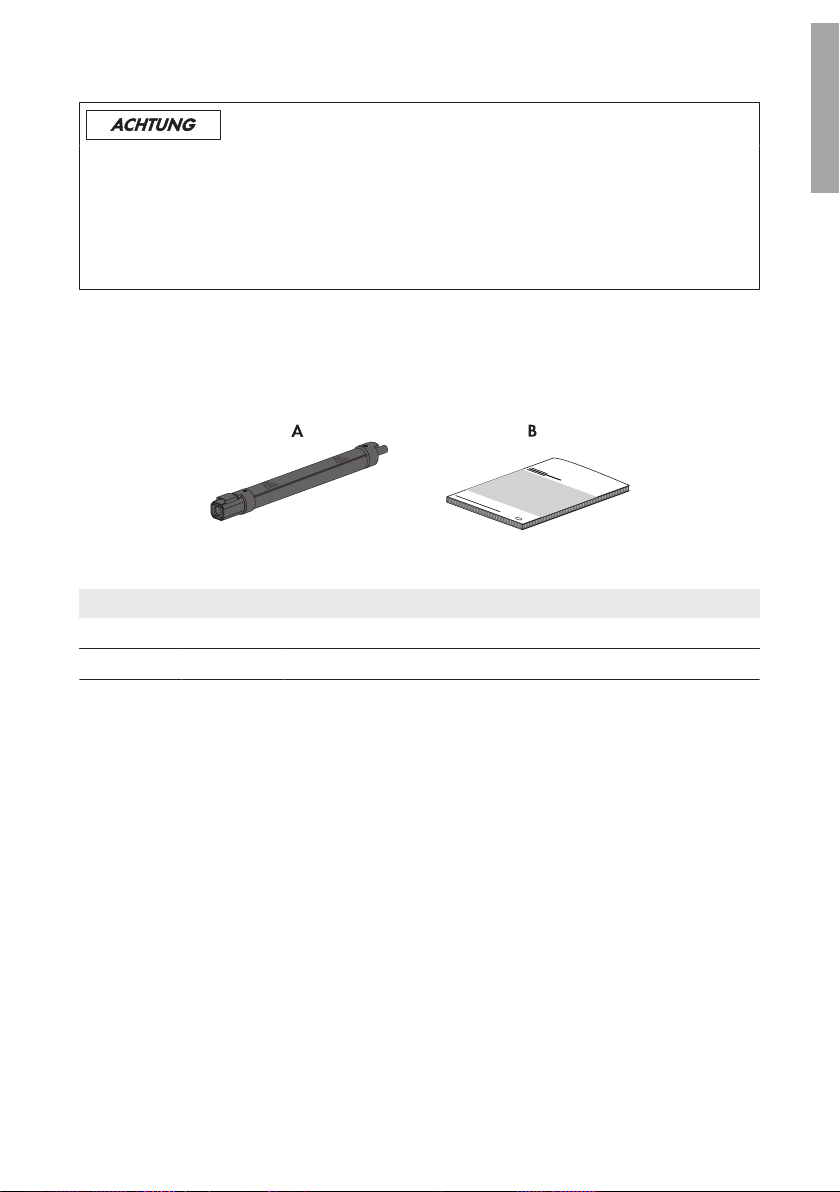
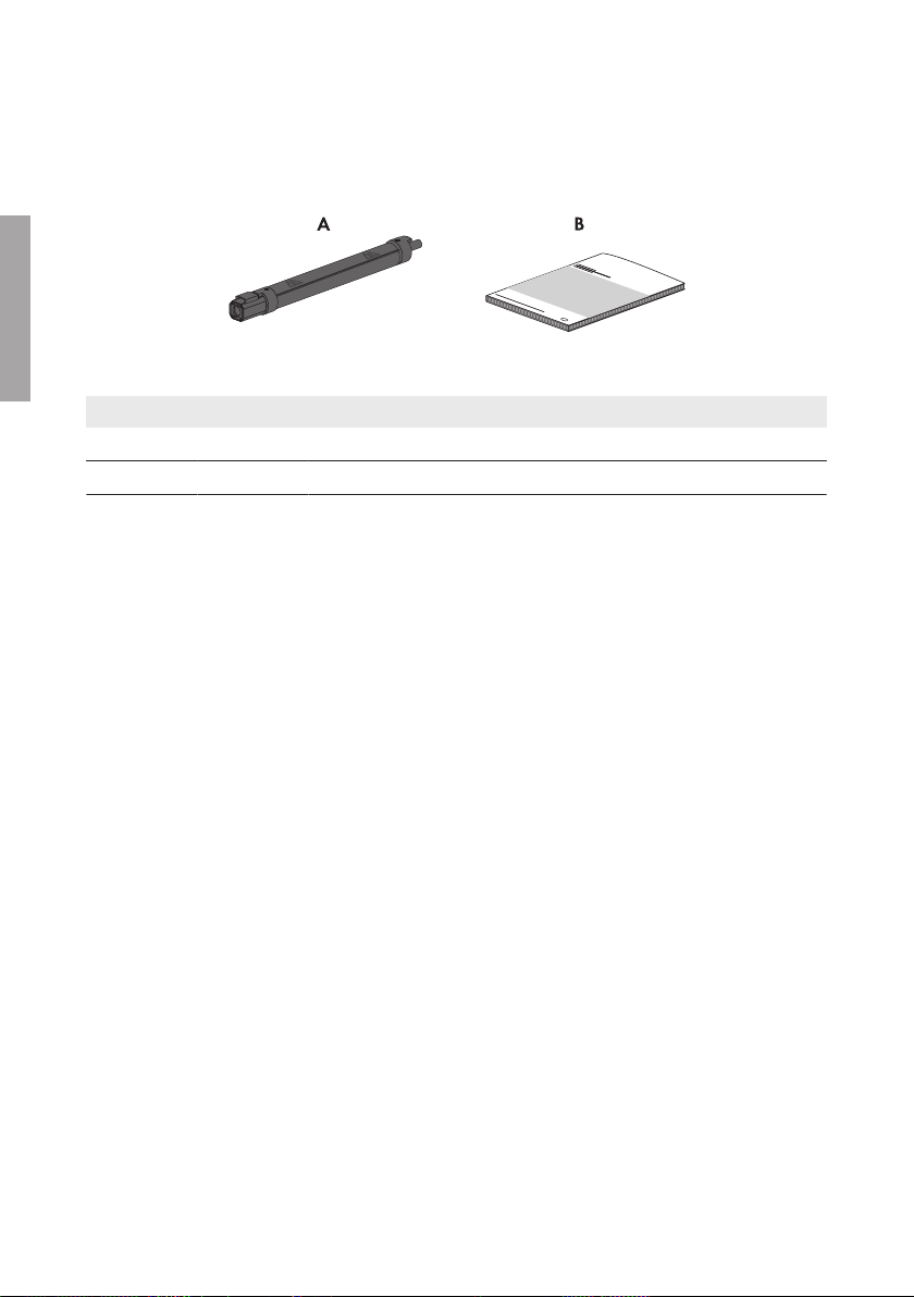
Prüfen Sie den Lieferumfang auf Vollständigkeit und äußerlich sichtbare Beschädigungen. Setzen
Sie sich bei unvollständigem Lieferumfang oder Beschädigungen mit Ihrem Fachhändler in
Verbindung.
Abbildung 1 : Bestandteile des Lieferumfangs
Position Anzahl Bezeichnung
A 16 Sicherungssteckverbinder
B 1 Installationsanleitung
DEUTSCH
4 Auslegung der Sicherungen
Die Sicherungssteckverbinder können ohne zusätzliches Derating bei Umgebungstemperaturen bis
+55°C im Bündel unter dem SMA String-Monitor eingesetzt werden. Bei der Auswahl der
richtigen Sicherungsnennwerte (I
des angeschlossenen PV-Generators bei Standard-Testbedingungen (ISC_STC) zu beziehen.
Es gilt:
ISC_STC ≤ I
x Reduktionsfaktor bzw. I
nenn
Der Reduktionsfaktor von 0,55 gilt bis zu einer maximalen Einstrahlung von 1.200W/m
(Stundenmittelwert der horizontalen Globalstrahlung). Werden noch höhere Einstrahlungen
erwartet, muss der Reduktionsfaktor entsprechend linear, bezogen auf 1.200W/m2, nach unten
angepasst werden.
Auslegung der Sicherungen bei einer Aufstellhöhe bis 2.000m
Bei der Auslegung der Sicherung müssen folgende Faktoren bei einer Aufstellhöhe bis zu 2.000m
berücksichtigt werden:
• Umgebungstemperatur: ‒40°C … +55°C
• Maximaler Bemessungsstrom pro Sicherung: 0,55 x I
Installationsanleitung 7InlineFuse-IA-xx-10
) ist der Reduktionsfaktor von 0,55 auf den Kurzschlussstrom
nenn
≥ ISC_STC / Reduktionsfaktor
nenn
nenn Sicherung
2
Page 8
DEUTSCH
5 Anforderungen an den Montageort
• Maximaler Bemessungsstrom pro Messkanal des Geräts
• Maximaler Strom für das Gerät
Die Rückstromfestigkeit von PV-Modulen muss bei der Auslegung beachtet werden.
SMA Solar Technology AG
Zusätzlicher Reduktionsfaktor bei einer Aufstellhöhe über 2.000 m
Bei einer Aufstellhöhe über 2.000m muss pro zusätzliche 100m Höhe ein zusätzlicher
Reduktionsfaktor von 0,5% bei der Auslegung der Sicherungen berücksichtigt werden.
Weitere Informationen erhalten Sie in der Technischen Information "IFCON Inline-Fuse-ConnectorSet16".
5 Anforderungen an den Montageort
☐ Umgebungstemperatur: ‒40°C … +55°C
☐ Die Sicherungssteckverbinder dürfen keine umliegenden Gegenstände berühren, die über
+55°C heiß werden.
6 Sicherungssteckverbinder montieren
Lebensgefahr durch Lichtbogen
Beim Stecken oder Trennen der DC-Steckverbinder oder der Sicherungssteckverbinder unter Last
und bei einem verpolten Anschluss der DC-Steckverbinder kann ein Lichtbogen entstehen. Bei
einem Lichtbogenereignis sind Tod oder schwere Verletzungen die Folge.
• Korrekte Polarität der PV-Strings vor Anschluss sicherstellen.
• DC-Steckverbinder oder Sicherungssteckverbinder nur im lastfreien Zustand stecken oder
trennen.
• Den DC-Unterverteiler freischalten (siehe Anleitung des DC-Unterverteilers).
• Geeignete persönliche Schutzausrüstung tragen.
Voraussetzungen:
☐ Die positiven Anschlusskabel der PV-Module müssen mit den positiven DC-Steckverbindern
ausgestattet sein (Informationen zum Konfektionieren der DC-Steckverbinder siehe
Installationsanleitung der DC-Steckverbinder).
☐ Die negativen Anschlusskabel der PV-Module müssen mit den negativen DC-Steckverbindern
ausgestattet sein (Informationen zum Konfektionieren der DC-Steckverbinder siehe
Installationsanleitung der DC-Steckverbinder).
Vorgehen:
1. Den DC-Unterverteiler freischalten (siehe Anleitung des DC-Unterverteilers).
2. Mit einem geeigneten Messgerät die Spannung an einem konfektionierten DC-Steckverbinder
eines Anschlusskabels der PV-Module messen.
3. Für diesen DC-Steckverbinder einen Sicherungssteckverbinder mit einer geeigneten
Nennstromstärke wählen.
InstallationsanleitungInlineFuse-IA-xx-108
Page 9
SMA Solar Technology AG
4. Das passende Ende des Sicherungssteckverbinders auf den konfektionierten DCSteckverbinder stecken. Dabei rastet der Sicherungssteckverbinder hörbar ein.
5. Das andere Ende des Sicherungssteckverbinders in den DC-Steckverbinder des DCUnterverteilers stecken. Dabei rastet der Sicherungssteckverbinder hörbar ein.
6. Sicherstellen, dass der DC-Steckverbinder fest installiert ist.
7. Das String-Kabel an der Kabelabfangschiene fixieren (siehe Betriebsanleitung des DCUnterverteilers). Dabei die Anordnung und Befestigung der String-Kabel beachten, damit die
Sicherungssteckverbinder nicht überhitzen.
8. Die Schritte für jeden DC-Steckverbinder der Anschlusskabel der PV-Module durchführen.
7 Sicherungssteckverbinder demontieren
7 Sicherungssteckverbinder demontieren
Lebensgefahr durch Lichtbogen
Beim Stecken oder Trennen der DC-Steckverbinder oder der Sicherungssteckverbinder unter Last
und bei einem verpolten Anschluss der DC-Steckverbinder kann ein Lichtbogen entstehen. Bei
einem Lichtbogenereignis sind Tod oder schwere Verletzungen die Folge.
• Korrekte Polarität der PV-Strings vor Anschluss sicherstellen.
• DC-Steckverbinder oder Sicherungssteckverbinder nur im lastfreien Zustand stecken oder
trennen.
• Den DC-Unterverteiler freischalten (siehe Anleitung des DC-Unterverteilers).
• Geeignete persönliche Schutzausrüstung tragen.
DEUTSCH
Verbrennungsgefahr durch heiße Sicherungssteckverbinder
Die Sicherungssteckverbinder werden im Betrieb bis zu 90°C heiß. Berühren der
Sicherungssteckverbinder kann zu Verbrennungen führen.
• Die Sicherungssteckverbinder nur mit geeigneter Schutzausrüstung berühren.
• Heiße, demontierte Sicherungssteckverbinder so ablegen, dass ein versehentliches Berühren
nicht möglich ist.
• Die Sicherungssteckverbinder so montieren, dass eine Luftzirkulation um die
Sicherungssteckverbinder möglich ist. Eine Kühlung der Sicherungssteckverbinder durch die
Umgebungsluft ist zwingend notwendig.
• Die Sicherungssteckverbinder so montieren, dass ein versehentliches Berühren nicht möglich
ist. Dabei darf die Luftzirkulation um die Sicherungssteckverbinder nicht verhindert werden.
Installationsanleitung 9InlineFuse-IA-xx-10
Page 10
DEUTSCH
8 Sicherungssteckverbinder warten
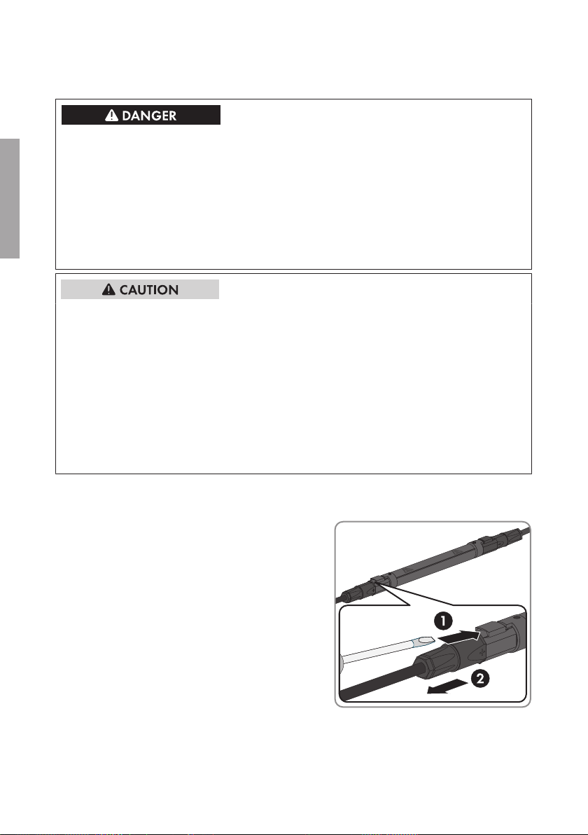
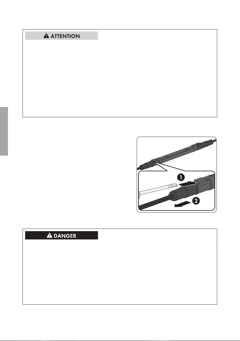
Vorgehen:
1. Den DC-Unterverteiler freischalten (siehe Anleitung des DC-Unterverteilers).
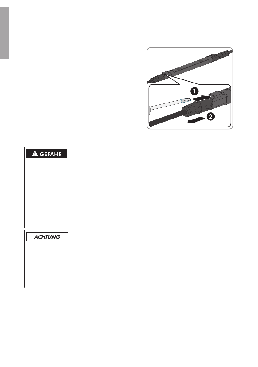
2. Einen Schraubendreher oder einen
abgewinkelten Federstecher (Klingenbreite:
3,5mm) in einen der seitlichen Schlitze des DCSteckverbinders stecken und den
Sicherungssteckverbinder gerade abziehen.
Dabei nicht an den String-Kabeln ziehen.
SMA Solar Technology AG
8 Sicherungssteckverbinder warten
Lebensgefahr durch Lichtbogen
Beim Stecken oder Trennen der DC-Steckverbinder oder der Sicherungssteckverbinder unter Last
und bei einem verpolten Anschluss der DC-Steckverbinder kann ein Lichtbogen entstehen. Bei
einem Lichtbogenereignis sind Tod oder schwere Verletzungen die Folge.
• Korrekte Polarität der PV-Strings vor Anschluss sicherstellen.
• DC-Steckverbinder oder Sicherungssteckverbinder nur im lastfreien Zustand stecken oder
trennen.
• Den DC-Unterverteiler freischalten (siehe Anleitung des DC-Unterverteilers).
• Geeignete persönliche Schutzausrüstung tragen.
Beschädigung der Sicherungssteckverbinder durch Verwendung von Kontaktreinigern
oder anderen Reinigungsmitteln
In einigen Kontaktreinigern oder anderen Reinigungsmitteln können Stoffe enthalten sein, die den
Kunststoff der Sicherungssteckverbinder zersetzen.
• Die Sicherungssteckverbinder nicht mit Kontaktreinigern oder anderen Reinigungsmitteln
behandeln.
Vorgehen:
1. Den DC-Unterverteiler freischalten (siehe Anleitung des DC-Unterverteilers).
2. Prüfen, ob die Sicherungssteckverbinder verformt sind.
Wenn die Sicherungssteckverbinder verformt sind, Service kontaktieren (siehe Kapitel10,
Seite11).
InstallationsanleitungInlineFuse-IA-xx-1010
Page 11
SMA Solar Technology AG
9 Technische Daten
9 Technische Daten
String-Sicherung
Nennstromstärke der String-Sicherungen 6ADC / 8ADC / 10ADC /12ADC / 15ADC /
20ADC / 25ADC / 30A
DC
Sicherungscharakteristik gPV
Größe des Sicherungssteckverbinder 1.000V
Größe des Sicherungssteckverbinder 1.500V
DC
DC
26,4mm x 175,0mm
26,4mm x 220,0mm
30,0mm x 220,0mm*
Maximaler Bemessungsstrom pro Sicherung 0,55 x I
Sicherung
nenn
Temperaturbereich ‒40°C … +55°C
Maximale Höhe über NHN** 4.000m
* 20A, 25A, 30A mit Abstandhalter
** Bei einer Aufstellhöhe über 2.000m muss pro zusätzliche 100m Höhe ein zusätzlicher Reduktionsfaktor
von 0,5% bei der Auslegung der Sicherungen berücksichtigt werden (siehe Technische Information
"IFCON Inline-Fuse-Connector-Set16").
10 Kontakt
Kontaktdaten finden Sie unter www.SMA-Solar.com.
DEUTSCH
Installationsanleitung 11InlineFuse-IA-xx-10
Page 12

ENGLISH
Table of Contents
SMA Solar Technology AG
Table of Contents
1 Information on this Document ................................................. 13
1.1 Validity................................................................................................ 13
1.2 Target Group...................................................................................... 13
1.3 Additional Information....................................................................... 13
1.4 Symbols .............................................................................................. 13
1.5 Nomenclature..................................................................................... 14
2 Safety......................................................................................... 14
2.1 Intended Use ...................................................................................... 14
2.2 Safety Information.............................................................................. 15
3 Scope of Delivery...................................................................... 16
4 Fuse Rating................................................................................ 16
5 Requirements for the Mounting Location ............................... 17
6 Mounting the Inline Fuse Connectors...................................... 17
7 Disassembling the Inline Fuse Connectors.............................. 18
8 Maintenance of Inline Fuse Connectors.................................. 19
9 Technical Data........................................................................... 19
10 Contact....................................................................................... 20
Installation ManualInlineFuse-IA-xx-1012
Page 13
SMA Solar Technology AG
1 Information on this Document
1 Information on this Document
1.1 Validity
This document is valid for the following product types (inline fuse connector set):
Product type
• IFCON16S0610
• IFCON16S0810
• IFCON16S1010
• IFCON16S1210
• IFCON16S1510
• IFCON16S2010
• IFCON16S2510
• IFCON16S3010
1.2 Target Group
The tasks described in this document must only be performed by qualified persons. Qualified
persons must have the following skills:
• Knowledge of how the product works and is operated
• Training in how to deal with the dangers and risks associated with installing and using
electrical devices and systems
• Training in the installation and commissioning of electrical devices and systems
• Knowledge of all applicable standards and directives
• Knowledge of and adherence to this manual and all safety precautions
• IFCON16S0615
• IFCON16S0815
• IFCON16S1015
• IFCON16S1215
• IFCON16S1515
• IFCON16S2015
• IFCON16S2515
• IFCON16S3015
ENGLISH
1.3 Additional Information
Links to additional information can be found at www.SMA-Solar.com:
Document title and content Document type
"IFCON Inline Fuse Connector Set16"
Information on rating, circuitry options and ac-
cessories
Technical Information
1.4 Symbols
Symbol Explanation
Indicates a hazardous situation which, if not avoided, will result in death or serious injury
Indicates a hazardous situation which, if not avoided, can result in death or serious injury
Installation Manual 13InlineFuse-IA-xx-10
Page 14
ENGLISH
2 Safety
Symbol Explanation
Indicates a hazardous situation which, if not avoided, can result in minor or moderate injury
Indicates a situation which, if not avoided, can result in property damage
Sections describing activities to be performed by
qualified persons only
Information that is important for a specific topic or
goal, but is not safety-relevant
Indicates a requirement for meeting a specific goal
Desired result
A problem that might occur
SMA Solar Technology AG
1.5 Nomenclature
Complete designation Designation in this document
Inline fuse connector set • Inline fuse connector set
• Product
SMA String-Monitor • SMA String-Monitor
• DC sub-distribution
2 Safety
2.1 Intended Use
The inline fuse connector is a string fuse which protects strings against reverse currents. The inline
fuse connector is connected to DC connectors or Y adapters of the SUNCLIX plug-in system.
All work on the product must only be performed using appropriate tools.
Observe the manufacturer specifications of the product.
Use this product only in accordance with the information provided in the enclosed documentation
and with the locally applicable standards and directives. Any other application may cause
personal injury or property damage.
Alterations to the product, e.g. changes or modifications, are only permitted with the express written
permission of SMA Solar Technology AG. Unauthorized alterations will void guarantee and
warranty claims and usually void the operation permit. SMA Solar Technology AG shall not be
held liable for any damage caused by such changes.
Any use of the product other than that described in the Intended Use section does not qualify as
appropriate.
The enclosed documentation is an integral part of this product. Keep the documentation in a
convenient place for future reference and observe all instructions contained therein.
Installation ManualInlineFuse-IA-xx-1014
Page 15
SMA Solar Technology AG
2 Safety
2.2 Safety Information
Danger to life from electric shock due to live voltage
High voltages are present in the live components of the DC sub-distribution. Touching live
components results in death or serious injury due to electric shock.
• Wear suitable personal protective equipment for all work on the product.
• Do not touch any live components.
• If live voltage is not absolutely necessary, disconnect all DC sub-distributions before working
on the DC sub-distribution and disconnect the inverter on the DC side (see manual of the DC
sub-distribution and of the inverter).
Danger to life due to high voltages on DC conductors
When exposed to sunlight, the PV array generates dangerous DC voltage which is present in the
DC conductors. Touching the DC conductors results in death or serious injury due to electric
shock.
• Cover the PV modules.
• Do not touch the DC conductors.
ENGLISH
Danger to life due to electric arc
An electric arc may occur when plugging or removing the DC connectors or the inline fuse
connectors under load and in case of a reverse-poled connection of the DC connectors. Electric
arcs can result in death or serious injury.
• Ensure the correct polarity of the strings before connection.
• Plug or remove DC connectors and inline fuse connectors only under load-free conditions.
• Disconnect the DC sub-distribution (see the DC sub-distribution manual).
• Wear suitable personal protective equipment.
Damage to the PV system due to incorrectly rated fuses
If fuses are incorrectly rated, excessive reverse currents can destroy the PV modules.
• Observe the maximum current values for the product when rating the fuses.
Damage to the DC connectors due the use of contact cleaner of other cleaning agents
Some contact cleaners or other cleaning agents may contain substances that decompose the
plastic of the DC connectors.
• Do not use contact cleaners or other cleaning agents for cleaning the DC connectors.
Installation Manual 15InlineFuse-IA-xx-10
Page 16
ENGLISH
3 Scope of Delivery
SMA Solar Technology AG
3 Scope of Delivery
Check the scope of delivery for completeness and any externally visible damage. Contact your
distributor if the scope of delivery is incomplete or damaged.
Figure 2 : Components included in the scope of delivery
Position Quantity Designation
A 16 Inline fuse connector
B 1 Installation Manual
4 Fuse Rating
The inline fuse connectors can be used in bundles underneath the SMAString-Monitor without
additional derating at ambient temperatures up to +55°C. When selecting the correct nominal fuse
values (I
array in standard test conditions (ISC_STC).
The following applies:
ISC_STC ≤ I
The reduction factor 0.55 applies for a maximum irradiation of 1,200W/m2 (hourly average value
of the horizontal global radiation). If even higher irradiation is to be expected, the reduction factor
must be linearly adapted downwards, based on 1,200W/m2.
), the reduction factor 0.55 must refer to the short-circuit current of the connected PV
nom
x reduction factor or I
nom
≥ ISC_STC/reduction factor
nom
Fuse Rating for Installation Altitudes up to 2,000m
When rating the fuses, the following factors for installation altitudes up to 2,000m must be taken
into account:
• Ambient temperature: ‒40°C to +55°C
• Maximum rated current per fuse: 0.55 x I
nom fuse
• Maximum rated current per measuring channel of the device
• Maximum current for the device
The reverse-current resistance of the PV modules must be taken into account for fuse rating.
Supplementary Reduction Factor for Installation Altitudes above 2,000m
For installation altitudes above 2,000m, an additional reduction factor of 0.5% for each additional
100m must be taken into account when rating the fuses.
For further information, refer to the Technical Information "IFCON Inline Fuse Connector Set16".
Installation ManualInlineFuse-IA-xx-1016
Page 17
SMA Solar Technology AG
5 Requirements for the Mounting Location
5 Requirements for the Mounting Location
☐ Ambient temperature: ‒40°C to +55°C
☐ The inline fuse connectors must not be in contact with surrounding objects with temperatures
exceeding +55°C.
6 Mounting the Inline Fuse Connectors
Danger to life due to electric arc
An electric arc may occur when plugging or removing the DC connectors or the inline fuse
connectors under load and in case of a reverse-poled connection of the DC connectors. Electric
arcs can result in death or serious injury.
• Ensure the correct polarity of the strings before connection.
• Plug or remove DC connectors and inline fuse connectors only under load-free conditions.
• Disconnect the DC sub-distribution (see the DC sub-distribution manual).
• Wear suitable personal protective equipment.
Requirements:
☐ The positive connection cables of the PV modules must be fitted with the positive DC
connectors (for information on assembling DC connectors, see the DC connector installation
manual).
☐ The negative connection cables of the PV modules must be fitted with the negative DC
connectors (for information on assembling DC connectors, see the DC connector installation
manual).
Procedure:
1. Disconnect the DC sub-distribution (see the DC sub-distribution manual).
2. Measure the voltage at an assembled DC connector of a connection cable of the PV modules
using an appropriate measuring device.
3. Select an inline fuse connector with appropriate nominal electrical current strength for this DC
connector.
4. Plug the suitable end of the inline fuse connector onto the assembled DC connector. The inline
fuse connector snaps into place.
5. Insert the other end of the inline fuse connector in the DC connector of the DC sub-distribution.
The inline fuse connector snaps into place.
6. Make sure that the DC connector is securely in place.
7. Secure the string cable on the cable support rail (see operating manual of the DC subdistribution). Observe the arrangement and fixation of the string cables to avoid overheating
of the inline fuse connectors.
8. Perform the steps for each DC connector of the connection cables of the PV modules.
ENGLISH
Installation Manual 17InlineFuse-IA-xx-10
Page 18
ENGLISH
7 Disassembling the Inline Fuse Connectors
SMA Solar Technology AG
7 Disassembling the Inline Fuse Connectors
Danger to life due to electric arc
An electric arc may occur when plugging or removing the DC connectors or the inline fuse
connectors under load and in case of a reverse-poled connection of the DC connectors. Electric
arcs can result in death or serious injury.
• Ensure the correct polarity of the strings before connection.
• Plug or remove DC connectors and inline fuse connectors only under load-free conditions.
• Disconnect the DC sub-distribution (see the DC sub-distribution manual).
• Wear suitable personal protective equipment.
Risk of burns due to hot inline fuse connectors
During operation, the temperature of the inline fuse connectors can reach up to 90°C. Touching
the inline fuse connectors can result in burns.
• Only touch the inline fuse connectors wearing suitable personal protective equipment.
• Position hot, removed inline fuse connectors in such a way that they cannot be touched
inadvertently.
• Mount the inline fuse connectors in such a way that air can circulate around them. Cooling
the inline fuse connectors by the ambient air is absolutely necessary.
• Mount the inline fuse connectors in such a way that they cannot be touched inadvertently.
Ensure that air circulation around the inline fuse connectors is not prevented.
Procedure:
1. Disconnect the DC sub-distribution (see the DC sub-distribution manual).
2. Insert a screwdriver or an angled screwdriver
(blade width: 3.5mm) into one of the side slots
of the DC connector and pull the inline fuse
connector straight out. Do not pull on the string
cables.
Installation ManualInlineFuse-IA-xx-1018
Page 19
SMA Solar Technology AG
8 Maintenance of Inline Fuse Connectors
8 Maintenance of Inline Fuse Connectors
Danger to life due to electric arc
An electric arc may occur when plugging or removing the DC connectors or the inline fuse
connectors under load and in case of a reverse-poled connection of the DC connectors. Electric
arcs can result in death or serious injury.
• Ensure the correct polarity of the strings before connection.
• Plug or remove DC connectors and inline fuse connectors only under load-free conditions.
• Disconnect the DC sub-distribution (see the DC sub-distribution manual).
• Wear suitable personal protective equipment.
Damage to the inline fuse connectors due the use of contact cleaner of other cleaning
agents
Some contact cleaners or other cleaning agents may contain substances that decompose the
plastic of the inline fuse connectors.
• Do not use contact cleaners or other cleaning agents for cleaning the inline fuse connectors.
Procedure:
1. Disconnect the DC sub-distribution (see the DC sub-distribution manual).
2. Check whether the inline fuse connectors are deformed.
If the inline fuse connectors are deformed, contact the Service (see Section10, page20).
ENGLISH
9 Technical Data
String fuse
Nominal current strength of string fuses 6ADC / 8ADC / 10ADC /12ADC / 15ADC /
20ADC / 25ADC / 30A
Fuse characteristics gPV
Size of inline fuse connector 1,000 V
Size of inline fuse connector 1,500 V
DC
DC
26.4mm x 175.0mm
26.4mmx220.0mm
30.0mm x 220.0mm*
Maximum rated current per fuse 0.55 x I
nom
Temperature range ‒40°C to +55°C
Maximum altitude above MSL** 4,000m
* 20A, 25A, 30A with spacer
** For installation altitudes above 2,000m, an additional reduction factor of 0.5% for each additional
100m must be taken into account when rating the fuses (see the Technical Information "IFCON Inline
Fuse Connector Set16").
Installation Manual 19InlineFuse-IA-xx-10
DC
fuse
Page 20

ENGLISH
10 Contact
10 Contact
You can find the contact data at www.SMA-Solar.com.
SMA Solar Technology AG
Installation ManualInlineFuse-IA-xx-1020
Page 21

SMA Solar Technology AG
Table des matières
Table des matières
1 Remarques relatives à ce document....................................... 22
1.1 Champ d’application......................................................................... 22
1.2 Groupe cible ...................................................................................... 22
1.3 Informations complémentaires........................................................... 22
1.4 Symboles ............................................................................................ 22
1.5 Nomenclature..................................................................................... 23
2 Sécurité ...................................................................................... 23
2.1 Utilisation conforme ........................................................................... 23
2.2 Consignes de sécurité........................................................................ 24
3 Contenu de la livraison ............................................................ 25
4 Dimensionnement des fusibles ................................................ 25
5 Exigences relatives au lieu de montage ................................. 26
6 Montage des connecteurs porte-fusible.................................. 26
7 Démontage des connecteurs porte-fusible ............................. 27
FRANÇAIS
8 Entretien des connecteurs porte-fusible .................................. 28
9 Caractéristiques techniques ..................................................... 29
10 Contact....................................................................................... 29
Instructions d’installation 21InlineFuse-IA-xx-10
Page 22
FRANÇAIS
1 Remarques relatives à ce document
SMA Solar Technology AG
1 Remarques relatives à ce document
1.1 Champ d’application
Ce document est valable pour les types de produits suivants (jeu de connecteurs porte-fusible):
Type de produit
• IFCON16S0610
• IFCON16S0810
• IFCON16S1010
• IFCON16S1210
• IFCON16S1510
• IFCON16S2010
• IFCON16S2510
• IFCON16S3010
1.2 Groupe cible
Les opérations décrites dans le présent document doivent uniquement être réalisées par un
personnel qualifié. Ce dernier doit posséder les qualifications suivantes:
• Connaissance du fonctionnement et de l’utilisation du produit
• Formation au comportement à adopter face aux dangers et risques encourus lors de
l’installation et de la manipulation d’appareils et installations électriques
• Formation à l’installation et à la mise en service des appareils et installations électriques
• Connaissance des normes et directives applicables
• Connaissance et respect des présentes instructions avec toutes les consignes de sécurité
• IFCON16S0615
• IFCON16S0815
• IFCON16S1015
• IFCON16S1215
• IFCON16S1515
• IFCON16S2015
• IFCON16S2515
• IFCON16S3015
1.3 Informations complémentaires
Pour obtenir des informations complémentaires, consultez le site www.SMA-Solar.com:
Titre et contenu du document Type de document
«IFCON Inline-Fuse-Connector-Set16»
Information pour le dimensionnement, possibi-
lités de connexion et accessoires
Information technique
1.4 Symboles
Symbole Explication
Consigne de sécurité dont le non-respect entraîne
inévitablement des blessures corporelles graves voire mortelles
Instructions d’installationInlineFuse-IA-xx-1022
Page 23
SMA Solar Technology AG
Symbole Explication
Consigne de sécurité dont le non-respect peut entraîner des blessures corporelles graves voire mortelles
Consigne de sécurité dont le non-respect peut entraîner des blessures corporelles légères ou de moyenne gravité
Consigne de sécurité dont le non-respect peut entraîner des dommages matériels
Chapitre décrivant des opérations qui ne doivent
être réalisées que par du personnel qualifié
Information importante sur un thème ou un objectif
précis, mais ne relevant pas de la sécurité
Condition devant être remplie pour atteindre un objectif précis
Résultat souhaité
Problème susceptible de survenir
1.5 Nomenclature
Désignation complète Désignation dans ce document
Jeu de connecteurs porte-fusible • Jeu de connecteurs porte-fusible
• Produit
SMA String-Monitor • SMA String-Monitor
• Sous-distributeur DC
2 Sécurité
FRANÇAIS
2 Sécurité
2.1 Utilisation conforme
Le connecteur porte-fusible est un fusible string et protège les strings contre les courants de retour.
Le connecteur porte-fusible est raccordé au connecteur DC ou à l’adaptateur du système de
connexion SUNCLIX.
Les interventions sur le produit doivent être exécutées uniquement avec des outils appropriés.
Suivez les instructions du fabricant du produit.
Utilisez ce produit exclusivement en conformité avec la documentation fournie ainsi qu’avec les
normes et directives en vigueur sur le site. Tout autre usage peut compromettre la sécurité des
personnes ou entraîner des dommages matériels.
Instructions d’installation 23InlineFuse-IA-xx-10
Page 24
2 Sécurité
SMA Solar Technology AG
Les interventions sur le produit (modifications ou transformations, par exemple) ne sont autorisées
qu’après accord écrit de SMA Solar Technology AG. Toute intervention non autorisée entraîne
l’annulation de la garantie légale et commerciale et en règle générale le retrait de l’autorisation
d’exploitation. SMA Solar Technology AG décline toute responsabilité en cas de dommages
résultant d’une telle intervention.
Toute utilisation du produit différente de celle décrite dans l’utilisation conforme est considérée
comme non conforme.
Les documents joints font partie intégrante du produit. Les documents doivent être lus, respectés et
rester accessibles à tout moment.
2.2 Consignes de sécurité
FRANÇAIS
Danger de mort par choc électrique dû à une tension
Les composants conducteurs du sous-distributeur DC sont soumis à de hautes tensions. Le contact
avec des composants conducteurs entraîne des blessures graves, voire la mort par choc
électrique.
• Portez toujours un équipement de protection individuelle adapté pour tous les travaux.
• Ne touchez pas les composants conducteurs.
• Avant toute intervention sur le sous-distributeur DC, mettez tous les sous-distributeurs DC et
l’onduleur côté DC hors tension s’il n’est pas absolument indispensable qu’ils soient sous
tension (voir les instructions du sous-distributeur DC et de l’onduleur).
Danger de mort dû à des hautes tensions sur les conducteurs DC
En cas d’ensoleillement, le générateur photovoltaïque produit une tension continue dangereuse
dans les conducteurs DC. Le contact avec des conducteurs DC entraîne des blessures graves,
voire la mort par choc électrique.
• Recouvrez les panneaux photovoltaïques.
• Ne touchez pas aux conducteurs DC.
Danger de mort dû à un arc électrique
En cas de connexion ou de déconnexion des connecteurs DC ou des connecteurs porte-fusible en
charge et en cas d’erreur de polarité lors du raccordement des connecteurs DC, il peut en résulter
un arc électrique. La formation d’un arc électrique peut entraîner la mort ou des blessures graves.
• Assurez-vous que la polarité des strings est correcte avant de procéder au raccordement.
• Ne connectez ou ne déconnectez les connecteurs DC ou les connecteurs porte-fusible que
lorsqu’ils sont hors charge.
• Mettez hors tension le sous-distributeurDC (voir les instructions du sous-distributeurDC).
• Portez un équipement de protection individuelle adapté.
Instructions d’installationInlineFuse-IA-xx-1024
Page 25
SMA Solar Technology AG
3 Contenu de la livraison
Endommagement de l’installation photovoltaïque par des fusibles mal dimensionnés
En cas de fusibles incorrectement dimensionnés, des courants de retour trop élevés peuvent
détruire les panneaux photovoltaïques.
• Lors du dimensionnement des fusibles, respectez les valeurs maximales du courant pour le
produit.
Endommagement du connecteur DC dû à l’utilisation du spray nettoyant contacts ou
d’autres produits nettoyants
Certains sprays nettoyants contacts ou d’autres produits nettoyants peuvent contenir des
substances qui dissolvent le plastique dans les connecteurs DC.
• Ne traitez pas les connecteurs DC avec des sprays nettoyants contacts ou d’autres produits
nettoyants.
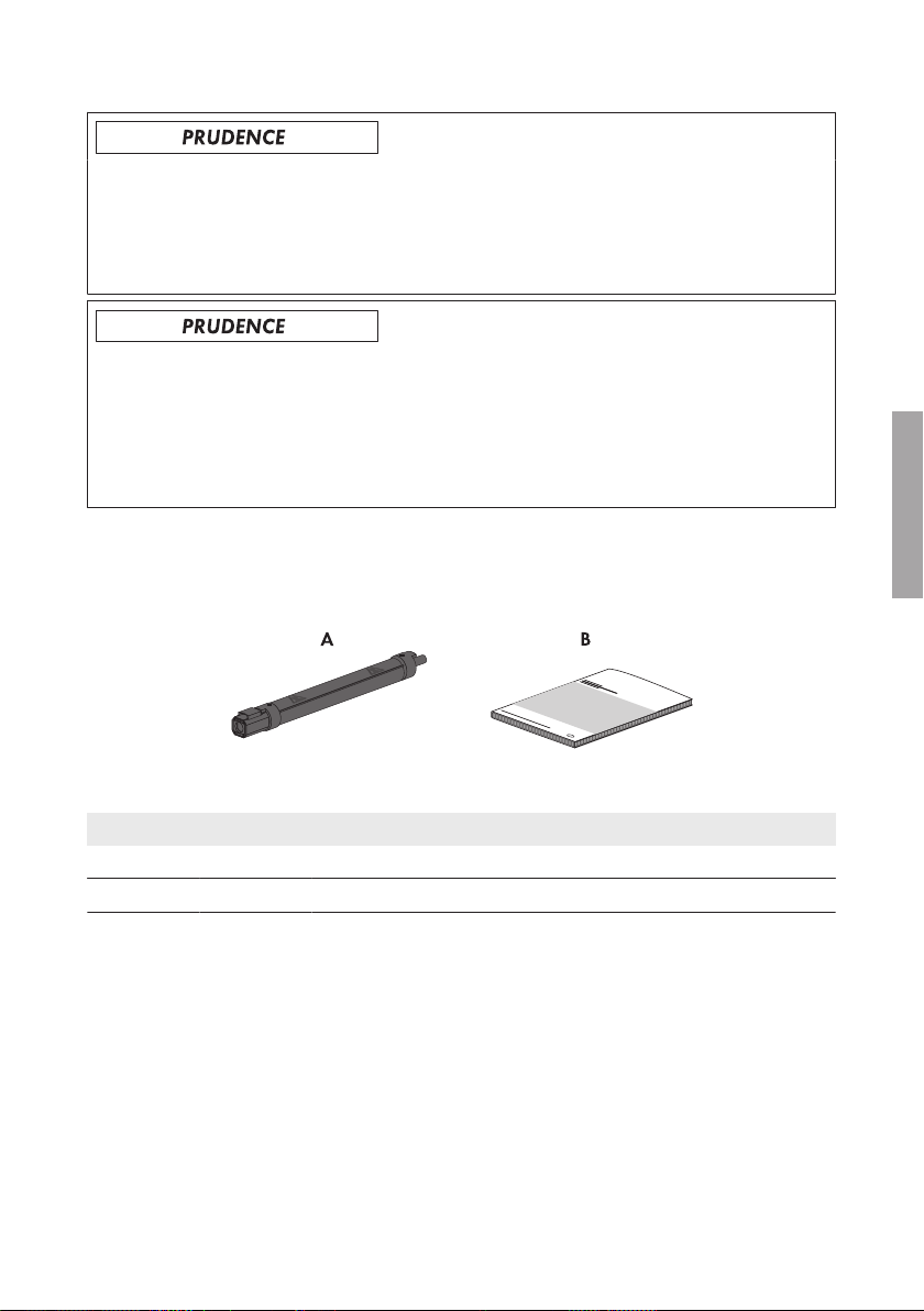
3 Contenu de la livraison
Vérifiez si la livraison est complète et ne présente pas de dommages apparents. En cas de livraison
incomplète ou de dommages, contactez votre revendeur.
Figure 3 : Éléments du contenu de livraison
Position Quantité Désignation
A 16 Connecteur porte-fusible
B 1 Instructions d’installation
4 Dimensionnement des fusibles
Les connecteurs porte-fusible peuvent être utilisés en faisceau sous le SMAString-Monitor sans
«derating» supplémentaire lorsque la température ambiante ne dépasse pas +55°C. Lors du
choix de la valeur nominale du fusible (I
de court-circuit du générateur photovoltaïque raccordé aux conditions de test
standardisées(ISC_STC).
La formule suivante s’applique:
ISC_STC ≤ I
x facteur de réduction ou bien I
nom
), le facteur de réduction de 0,55 se réfère au courant
nom
≥ ISC_STC / facteur de réduction
nom
FRANÇAIS
Instructions d’installation 25InlineFuse-IA-xx-10
Page 26
5 Exigences relatives au lieu de montage
SMA Solar Technology AG
FRANÇAIS
Le facteur de réduction de 0,55 s’applique jusqu’à un rayonnement maximal de 1200W/m
(moyenne horaire du rayonnement global horizontale). En cas d’un rayonnement plus élevé, le
facteur de réduction doit être adapté à la baisse de manière linéaire (par rapport à 1200W/m2).
2
Dimensionnement des fusibles à une altitude d’installation jusqu’à 2000m
Pour une altitude d’installation jusqu’à 2000m, les facteurs suivants doit être prendre en compte
lors du dimensionnement des fusibles:
• Température ambiante: ‒40°C à +55°C
• Courant assigné maximal par fusible: 0,55 x I
• Courant assigné maximal par canal de mesure de l’appareil
• Courant maximal pour l’appareil
Il est impératif de prendre en compte la résistance au courant de retour des panneaux
photovoltaïques lors du dimensionnement.
nom fusible
Facteur de réduction supplémentaire en cas d’installation à une altitude
supérieure à 2000m
En cas d’installation à une altitude supérieure à 2000 m, il faut prendre en compte un facteur de
réduction supplémentaire de 0,5% par 100m d’altitude supplémentaire lors du dimensionnement
des fusibles.
Pour de plus amples informations, voir l’information technique «IFCON Inline-Fuse-ConnectorSet16».
5 Exigences relatives au lieu de montage
☐ Température ambiante: ‒40°C à +55°C
☐ Les connecteur porte-fusible ne doivent pas toucher les objets avoisinants devenant plus chaud
que +55°C.
6 Montage des connecteurs porte-fusible
Danger de mort dû à un arc électrique
En cas de connexion ou de déconnexion des connecteurs DC ou des connecteurs porte-fusible en
charge et en cas d’erreur de polarité lors du raccordement des connecteurs DC, il peut en résulter
un arc électrique. La formation d’un arc électrique peut entraîner la mort ou des blessures graves.
• Assurez-vous que la polarité des strings est correcte avant de procéder au raccordement.
• Ne connectez ou ne déconnectez les connecteurs DC ou les connecteurs porte-fusible que
lorsqu’ils sont hors charge.
• Mettez hors tension le sous-distributeurDC (voir les instructions du sous-distributeurDC).
• Portez un équipement de protection individuelle adapté.
Instructions d’installationInlineFuse-IA-xx-1026
Page 27
SMA Solar Technology AG
Conditions préalables:
☐ Les câbles de raccordement positifs des panneaux photovoltaïques doivent être équipés des
connecteurs DC positifs (pour plus d’informations sur l’assemblage des connecteurs DC, voir
les instructions d’installation des connecteurs DC).
☐ Les câbles de raccordement négatifs des panneaux photovoltaïques doivent être équipés des
connecteurs DC négatifs (pour plus d’informations sur l’assemblage des connecteurs DC, voir
les instructions d’installation des connecteurs DC).
Procédure:
1. Mettez hors tension le sous-distributeurDC (voir les instructions du sous-distributeurDC).
2. À l’aide d’un appareil de mesure approprié, mesurez la tension à un connecteur DC
confectionné d’un câble de raccordement des panneaux photovoltaïques.
3. Sélectionnez un connecteur porte-fusible avec une intensité du courant adapté pour ce
connecteur DC.
4. Fichez l’extrémité correspondant du connecteur porte-fusible dans le connecteur DC
confectionné. Le connecteur porte-fusible s’enclenche de manière audible.
5. Fichez l’autre extrémité du connecteur porte-fusible dans le connecteur DC du sous-distributeur
DC. Le connecteur porte-fusible s’enclenche de manière audible.
6. Assurez-vous que le connecteur DC est bien installé.
7. Fixez le câble string au rail de fixation des câbles (voir les instructions d’emploi du sousdistributeur DC). Assurez-vous que les câbles string sont placés et fixés de manière qu’ils ne
surchauffent pas.
8. Exécutez la procédure pour tous les connecteurs DC du câble de raccordement des panneaux
photovoltaïques.
7 Démontage des connecteurs porte-fusible
FRANÇAIS
7 Démontage des connecteurs porte-fusible
Danger de mort dû à un arc électrique
En cas de connexion ou de déconnexion des connecteurs DC ou des connecteurs porte-fusible en
charge et en cas d’erreur de polarité lors du raccordement des connecteurs DC, il peut en résulter
un arc électrique. La formation d’un arc électrique peut entraîner la mort ou des blessures graves.
• Assurez-vous que la polarité des strings est correcte avant de procéder au raccordement.
• Ne connectez ou ne déconnectez les connecteurs DC ou les connecteurs porte-fusible que
lorsqu’ils sont hors charge.
• Mettez hors tension le sous-distributeurDC (voir les instructions du sous-distributeurDC).
• Portez un équipement de protection individuelle adapté.
Instructions d’installation 27InlineFuse-IA-xx-10
Page 28
FRANÇAIS
8 Entretien des connecteurs porte-fusible
Risque de brûlure dû à des connecteurs porte-fusible brûlants
Les connecteurs porte-fusible peuvent atteindre une température jusqu’à 90°C pendant le
fonctionnement. Le contact avec les connecteurs porte-fusible peut provoquer des brûlures.
• Portez un équipement de protection adapté avant de toucher les connecteurs porte-fusible.
• Déposez les connecteurs porte-fusible chauds et démontés de façon à exclure tout contact
involontaire.
• Montez les connecteurs porte-fusible de façon à permettre une bonne circulation de l’air
autour de ces derniers. Il est absolument indispensable qu’un refroidissement des
connecteurs porte-fusible par l’air ambiant soit garanti.
• Montez les connecteurs porte-fusible de façon à exclure tout contact involontaire. Ce faisant,
veillez à ce que la circulation de l’air autour des connecteurs ne soit pas entravée.
Procédure:
1. Mettez hors tension le sous-distributeurDC (voir les instructions du sous-distributeurDC).
2. Insérez un tournevis ou un pousse-ressort coudé
(largeur de lame: 3,5mm) dans l’une des
encoches latérales du connecteur DC et retirez
le connecteur porte-fusible en ligne droite. Ne
tirez pas sur les câbles string.
SMA Solar Technology AG
8 Entretien des connecteurs porte-fusible
Danger de mort dû à un arc électrique
En cas de connexion ou de déconnexion des connecteurs DC ou des connecteurs porte-fusible en
charge et en cas d’erreur de polarité lors du raccordement des connecteurs DC, il peut en résulter
un arc électrique. La formation d’un arc électrique peut entraîner la mort ou des blessures graves.
• Assurez-vous que la polarité des strings est correcte avant de procéder au raccordement.
• Ne connectez ou ne déconnectez les connecteurs DC ou les connecteurs porte-fusible que
lorsqu’ils sont hors charge.
• Mettez hors tension le sous-distributeurDC (voir les instructions du sous-distributeurDC).
• Portez un équipement de protection individuelle adapté.
Instructions d’installationInlineFuse-IA-xx-1028
Page 29

SMA Solar Technology AG
9 Caractéristiques techniques
Endommagement des connecteurs porte-fusible dû à l’utilisation du spray nettoyant
contact ou d’autres produits nettoyants
Certains sprays nettoyants contacts ou d’autres produits nettoyants peuvent contenir des
substances qui dissolvent le plastique dans les connecteurs porte-fusible.
• Ne traitez pas les connecteurs porte-fusible avec des sprays nettoyants contacts ou d’autres
produits nettoyants.
Procédure:
1. Mettez hors tension le sous-distributeurDC (voir les instructions du sous-distributeurDC).
2. Vérifiez que les connecteurs porte-fusible sont déformés.
Si les connecteurs porte-fusible sont déformés, contactez le Service (voir chapitre10, page
29).
9 Caractéristiques techniques
Fusible string
Intensité du courant nominal des fusibles string 6ADC / 8ADC / 10ADC /12ADC / 15ADC /
20ADC / 25ADC / 30A
Caractéristiques des fusibles gPV
Taille du connecteur porte-fusible 1 000V
Taille du connecteur porte-fusible 1 500V
DC
DC
26,4mm x 175,0mm
26,4mm x 220,0mm
30,0mm x 220,0mm*
Courant assigné maximal par fusible 0,55 x I
nom
fusible
Plage de température ‒40°C à +55°C
Altitude maximale au-dessus du niveau moyen
4 000m
de la mer**
* 20A, 25A, 30A avec entretoise
** En cas d’installation à une altitude supérieure à 2000 m, il faut prendre en compte un facteur de
réduction supplémentaire de 0,5% par 100m d’altitude supplémentaire lors du dimensionnement des
fusibles (voir information technique «IFCON Inline-Fuse-Connector-Set16»).
DC
FRANÇAIS
10 Contact
Vous trouverez les coordonnées sur www.SMA-Solar.com.
Instructions d’installation 29InlineFuse-IA-xx-10
Page 30

Índice
SMA Solar Technology AG
Índice
1 Indicaciones sobre este documento........................................ 31
1.1 Área de validez.................................................................................. 31
1.2 Grupo de destinatarios...................................................................... 31
1.3 Información adicional........................................................................ 31
1.4 Símbolos ............................................................................................. 31
1.5 Nomenclatura .................................................................................... 32
2 Seguridad.................................................................................. 32
2.1 Uso previsto........................................................................................ 32
2.2 Indicaciones de seguridad ................................................................ 33
3 Contenido de la entrega .......................................................... 34
4 Configuración de los fusibles................................................... 34
5 Requisitos para el lugar de montaje....................................... 35
ESPAÑOL
6 Montaje de los conectores con fusible integrado.................. 35
7 Desmontaje de los conectores con fusible integrado............ 36
8 Mantenimiento de los conectores con fusible integrado....... 38
9 Datos técnicos ........................................................................... 38
10 Contacto .................................................................................... 39
Instrucciones de instalaciónInlineFuse-IA-xx-1030
Page 31

SMA Solar Technology AG
1 Indicaciones sobre este documento
1 Indicaciones sobre este documento
1.1 Área de validez
Este documento es válido para estos tipos de producto (juego de conectores con fusible
integrado):
Tipo de producto
• IFCON16S0610
• IFCON16S0810
• IFCON16S1010
• IFCON16S1210
• IFCON16S1510
• IFCON16S2010
• IFCON16S2510
• IFCON16S3010
1.2 Grupo de destinatarios
Las actividades descritas en este documento deben realizarlas exclusivamente especialistas que
han de contar con esta cualificación:
• Conocimientos sobre los procedimientos y el funcionamiento del producto
• Formación sobre cómo actuar ante los peligros y riesgos relativos a la instalación y el manejo
de equipos eléctricos y plantas fotovoltaicas
• Formación profesional para la instalación y la puesta en marcha de equipos eléctricos y
plantas
• Conocimiento de las normativas y directivas aplicables
• Conocimiento y seguimiento de estas instrucciones y de todas sus indicaciones de seguridad
• IFCON16S0615
• IFCON16S0815
• IFCON16S1015
• IFCON16S1215
• IFCON16S1515
• IFCON16S2015
• IFCON16S2515
• IFCON16S3015
ESPAÑOL
1.3 Información adicional
Encontrará enlaces a información detallada en la página web www.SMA-Solar.com:
Título y contenido del documento Tipo de documento
“IFCON Inline-Fuse-Connector-Set16”
Información acerca de la configuración, las op-
ciones de conexión y los accesorios
Información técnica
1.4 Símbolos
Símbolo Explicación
Advertencia que, de no ser observada, causa la
muerte o lesiones físicas graves
Instrucciones de instalación 31InlineFuse-IA-xx-10
Page 32

ESPAÑOL
2 Seguridad
Símbolo Explicación
Advertencia que, de no ser observada, puede
causar la muerte o lesiones físicas graves
Advertencia que, de no ser observada, puede
causar lesiones físicas leves o de gravedad media
Advertencia que, de no ser observada, puede
causar daños materiales
Capítulos en los que se describen tareas que deben ser llevadas a cabo únicamente por especialistas
Información importante para un tema u objetivo
concretos, aunque no relevante para la seguridad
Requisito necesario para alcanzar un objetivo determinado
Resultado deseado
Posible problema
SMA Solar Technology AG
1.5 Nomenclatura
Denominación completa Denominación utilizada en este documento
Juego de conectores con fusible integrado • Juego de conectores con fusible integrado
• Producto
SMAString-Monitor • SMAString-Monitor
• Subdistribuidor de CC
2 Seguridad
2.1 Uso previsto
El conector con fusible integrado es un fusible de string que protege a los strings de la corriente
inversa. El conector con fusible integrado se conecta a conectadores de enchufe de CC o
adaptadores en Y del sistema de conexión de Sunclix.
Todos los trabajos en el producto deberán realizarse exclusivamente con las herramientas
apropiadas.
Siga las instrucciones del fabricante del producto.
Utilice siempre el producto de acuerdo con las indicaciones de la documentación adjunta y
observe las normativas y directivas locales vigentes. Cualquier otro uso puede causarle lesiones al
usuario o daños materiales.
Instrucciones de instalaciónInlineFuse-IA-xx-1032
Page 33

SMA Solar Technology AG
2 Seguridad
Para realizar cualquier intervención en el producto, como modificaciones o remodelaciones,
deberá contar con el permiso expreso y por escrito de SMA Solar Technology AG. Los cambios no
autorizados pueden conducir a la pérdida de los derechos de garantía así como a la extinción del
permiso de explotación. Queda excluida la responsabilidad de SMA Solar Technology AG por los
daños derivados de dichos cambios.
Cualquier uso del producto distinto al descrito en el uso previsto se considerará uso inadecuado.
La documentación adjunta es parte integrante del producto. La documentación debe leerse,
observarse y conservarse en un lugar accesible en todo momento.
2.2 Indicaciones de seguridad
Peligro de muerte por descarga eléctrica debido a la tensión
En los componentes conductores del subdistribuidor de CC existen altas tensiones. Tocar
componentes conductores de tensión puede causar la muerte o lesiones graves por descargas
eléctricas.
• Utilice un equipamiento de protección personal adecuado en todos los trabajos.
• No toque ningún componente bajo tensión.
• Antes de realizar cualquier trabajo en el subdistribuidor de CC, desconecte, si no es
imprescindible, la tensión de todos los subdistribuidores de CC y el inversor del lado de la
CC (consulte las instrucciones del subdistribuidor de CC y del inversor).
Peligro de muerte por altas tensiones en los conductores de CC
Cuando recibe luz solar, el generador fotovoltaico produce una tensión de CC peligrosa que se
acopla a los conductores de CC. Tocar los conductores de CC puede causar la muerte o
lesiones graves por descarga eléctrica.
• Cubra los módulos fotovoltaicos.
• No toque los conductores de CC.
Peligro de muerte por arcos voltaicos
Al enchufar y desconectar bajo carga los conectadores de enchufe de CC o conectores con
fusible integrado y en caso de que los conectadores de enchufe estén conectados con polos
invertidos, pueden producirse arcos voltaicos. El arco voltaico puede causar lesiones graves o la
muerte.
• Antes de conectar los strings, asegúrese de que la polaridad sea correcta.
• Solo enchufe y desconecte los conectadores de enchufe de CC o conectores con fusible
integrado cuando no estén bajo carga.
• Desconecte el subdistribuidor de CC (consulte las instrucciones del subdistribuidor de CC).
• Utilice un equipamiento de protección personal adecuado.
Instrucciones de instalación 33InlineFuse-IA-xx-10
ESPAÑOL
Page 34

ESPAÑOL
3 Contenido de la entrega
SMA Solar Technology AG
Daños en la planta fotovoltaica por fusibles dimensionados de manera incorrecta
En caso de fusibles dimensionados de manera incorrecta se pueden producir corrientes inversas
demasiado altas que destruyen los módulos fotovoltaicos.
• Tenga en cuenta los valores máximos de corriente del producto al diseñar los fusibles.
Daños en los conectadores de enchufe de CC por la utilización de limpiadores de
contacto y otros productos de limpieza
Algunos de ellos pueden contener sustancias que descomponen el plástico de los conectadores
de enchufe de CC.
• Por ello, no utilice limpiadores de contacto u otros productos de limpieza para los
conectadores de enchufe de CC.
3 Contenido de la entrega
Compruebe que el contenido de la entrega esté completo y que no presente daños externos
visibles. En caso de que no esté completo o presente daños, póngase en contacto con su
distribuidor.
Imagen 4 : Contenido de la entrega
Posición Cantidad Denominación
A 16 Conector con fusible integrado
B 1 Instrucciones de instalación
4 Configuración de los fusibles
Los conectores con fusible integrado se pueden conectar en conjunto debajo del SMAStringMonitor con temperaturas ambiente de hasta +55°C sin que se produzca un derrateo. Para
seleccionar los valores nominales adecuados de los fusibles (I
reducción de 0,55 a la corriente de cortocircuito del generador fotovoltaico conectado bajo
condiciones de prueba estándar (ISC_STC).
Donde:
ISC_STC≤I
x factor de reducción o I
nom
≥ISC_STC/factor de reducción
nom
), se debe aplicar el factor de
nom
Instrucciones de instalaciónInlineFuse-IA-xx-1034
Page 35

SMA Solar Technology AG
El factor de reducción de 0,55 se aplica hasta una irradiación máxima de 1000W/m2 (valor
medio por hora de la irradiación global horizontal). Si se prevé una irradiación aún mayor, el
factor de reducción debe ajustarse linealmente (en relación a los 1200W/m2) hacia abajo.
5 Requisitos para el lugar de montaje
Configuración de los fusibles a una altura de colocación de hasta 2000m
Al configurar los fusibles a una altura de colocación de hasta 2000m deben tenerse en cuenta
estos factores:
• Temperatura ambiente: ‒40°C … +55°C
• Corriente asignada máxima por fusible: 0,55 x I
• Corriente asignada máxima por canal de medición del equipo
• Corriente máxima del equipo
Al realizar la configuración debe tenerse en cuenta la resistencia de los módulos fotovoltaicos
frente a corrientes inversas.
nom fusible
Factor de reducción adicional a una altura de colocación superior a 2000m
Al configurar los fusibles a una altura de colocación superior a 2000m se debe calcular un factor
de reducción adicional de 0,5% por cada 100m adicionales.
Encontrará información adicional en la información técnica “IFCON Inline-Fuse-Connector-Set16”.
5 Requisitos para el lugar de montaje
☐ Temperatura ambiente: ‒40°C … +55°C
☐ Los conectores con fusible integrado no deben entrar en contacto con objetos que superen los
+55°C de temperatura.
6 Montaje de los conectores con fusible integrado
Peligro de muerte por arcos voltaicos
Al enchufar y desconectar bajo carga los conectadores de enchufe de CC o conectores con
fusible integrado y en caso de que los conectadores de enchufe estén conectados con polos
invertidos, pueden producirse arcos voltaicos. El arco voltaico puede causar lesiones graves o la
muerte.
• Antes de conectar los strings, asegúrese de que la polaridad sea correcta.
• Solo enchufe y desconecte los conectadores de enchufe de CC o conectores con fusible
integrado cuando no estén bajo carga.
• Desconecte el subdistribuidor de CC (consulte las instrucciones del subdistribuidor de CC).
• Utilice un equipamiento de protección personal adecuado.
Instrucciones de instalación 35InlineFuse-IA-xx-10
ESPAÑOL
Page 36

ESPAÑOL
7 Desmontaje de los conectores con fusible integrado
Requisitos:
☐ Los cables de conexión positivos de los módulos fotovoltaicos deben estar equipados con
conectadores de enchufe de CC positivos. Para obtener más información sobre la
preparación de los conectadores de enchufe de CC, consulte las instrucciones de instalación
de los conectadores de enchufe de CC.
☐ Los cables de conexión negativos de los módulos fotovoltaicos deben estar equipados con
conectadores de enchufe de CC negativos. Para obtener más información sobre la
preparación de los conectadores de enchufe de CC, consulte las instrucciones de instalación
de los conectadores de enchufe de CC.
Procedimiento:
1. Desconecte el subdistribuidor de CC (consulte las instrucciones del subdistribuidor de CC).
2. Mida con un equipo de medición adecuado la tensión en el conectador de enchufe de CC
confeccionado de uno de los cables de conexión de los módulos fotovoltaicos.
3. Para este conectador de enchufe de CC, escoja un conector con fusible integrado con una
corriente nominal adecuada.
4. Inserte el extremo correspondiente del conector con fusible integrado en el conectador de
enchufe de CC confeccionado. El conector con fusible integrado encaja de forma audible.
5. Inserte el otro extremo del conector con fusible integrado en el conectador de enchufe de CC
del subdistribuidor de CC. El conector con fusible integrado encaja de forma audible.
6. Asegúrese de que el conectador de enchufe de CC esté bien fijos.
7. Fije el cable del string al riel para el paso de los cables (consulte las instrucciones de
funcionamiento del subdistribuidor de CC). Siga las indicaciones de disposición y fijación de
los cables de los strings para que no se sobrecalienten los conectores con fusible integrado.
8. Siga estos pasos para cada conectador de enchufe de CC de los cables de conexión de los
módulos fotovoltaicos.
SMA Solar Technology AG
7 Desmontaje de los conectores con fusible integrado
Peligro de muerte por arcos voltaicos
Al enchufar y desconectar bajo carga los conectadores de enchufe de CC o conectores con
fusible integrado y en caso de que los conectadores de enchufe estén conectados con polos
invertidos, pueden producirse arcos voltaicos. El arco voltaico puede causar lesiones graves o la
muerte.
• Antes de conectar los strings, asegúrese de que la polaridad sea correcta.
• Solo enchufe y desconecte los conectadores de enchufe de CC o conectores con fusible
integrado cuando no estén bajo carga.
• Desconecte el subdistribuidor de CC (consulte las instrucciones del subdistribuidor de CC).
• Utilice un equipamiento de protección personal adecuado.
Instrucciones de instalaciónInlineFuse-IA-xx-1036
Page 37

SMA Solar Technology AG
7 Desmontaje de los conectores con fusible integrado
Peligro de quemaduras debido a conectores con fusible integrado calientes
Durante el funcionamiento, los conectores con fusible integrado se calientan, pudiendo alcanzar
temperaturas de hasta 90°C. Si se tocan los conectores con fusible integrado, pueden
producirse quemaduras.
• Solo toque los conectores con fusible integrado utilizando el equipamiento de protección
apropiado.
• Deposite los conectores con fusible integrado que haya desmontado y aún estén calientes
de tal manera que no sea posible un contacto accidental.
• Monte los conectores con fusible integrado de tal forma que el aire pueda circular en torno
a estos. La refrigeración de los conectores a través del aire es absolutamente necesaria.
• Monte los conectores con fusible integrado de tal manera que no sea posible un contacto
accidental. Preste atención a no obstaculizar la circulación del aire en torno a los
conectores.
Procedimiento:
1. Desconecte el subdistribuidor de CC (consulte las instrucciones del subdistribuidor de CC).
2. Introduzca un destornillador o una llave
acodada (hoja: 3,5mm) en una de las ranuras
laterales del conectador de enchufe de CC y
retire el conector con fusible integrado tirando
en línea recta. No tire de los cables de los
strings.
ESPAÑOL
Instrucciones de instalación 37InlineFuse-IA-xx-10
Page 38

ESPAÑOL
8 Mantenimiento de los conectores con fusible integrado
SMA Solar Technology AG
8 Mantenimiento de los conectores con fusible
integrado
Peligro de muerte por arcos voltaicos
Al enchufar y desconectar bajo carga los conectadores de enchufe de CC o conectores con
fusible integrado y en caso de que los conectadores de enchufe estén conectados con polos
invertidos, pueden producirse arcos voltaicos. El arco voltaico puede causar lesiones graves o la
muerte.
• Antes de conectar los strings, asegúrese de que la polaridad sea correcta.
• Solo enchufe y desconecte los conectadores de enchufe de CC o conectores con fusible
integrado cuando no estén bajo carga.
• Desconecte el subdistribuidor de CC (consulte las instrucciones del subdistribuidor de CC).
• Utilice un equipamiento de protección personal adecuado.
Daños en los conectores con fusible integrado por la utilización de limpiadores de
contacto y otros productos de limpieza
Algunos de ellos pueden contener sustancias que descomponen el plástico de los conectores con
fusible integrado.
• Por ello, no utilice limpiadores de contacto u otros productos de limpieza para los
conectores con fusible integrado.
Procedimiento:
1. Desconecte el subdistribuidor de CC (consulte las instrucciones del subdistribuidor de CC).
2. Compruebe si los conectores con fusible integrado se han deformado.
Si los conectores con fusible integrado se han deformado, póngase en contacto con el
servicio técnico (consulte el capítulo10, página39).
9 Datos técnicos
Fusible de string
Corriente nominal de los fusibles de string 6ACC/8ACC/10ACC/12ACC/15ACC/20A
/25ACC/30A
Característica de los fusibles gPV
Dimensiones del conector con fusible integrado
1000V
CC
Dimensiones del conector con fusible integrado
1500V
CC
26,4mm x 175,0mm
26,4mm x 220,0mm
30,0mm x 220,0mm*
Corriente asignada máxima por fusible 0,55 x I
nom
Instrucciones de instalaciónInlineFuse-IA-xx-1038
CC
fusible
CC
Page 39

SMA Solar Technology AG
10 Contacto
Fusible de string
Rango de temperatura ‒40°C … +55°C
Altura máxima sobre el nivel del mar** 4000m
* 20A, 25A, 30A con espaciador
** Al configurar los fusibles a una altura de colocación superior a 2000m se debe calcular un factor de
reducción adicional de 0,5% por cada 100m adicionales (consulte la información técnica “IFCON
Inline-Fuse-Connector-Set16”).
10 Contacto
Encontrará la información de contacto en www.SMA-Solar.com.
Instrucciones de instalación 39InlineFuse-IA-xx-10
ESPAÑOL
Page 40

Índice
SMA Solar Technology AG
Índice
1 Observações relativas a este documento .............................. 41
1.1 Aplicabilidade.................................................................................... 41
1.2 Grupo-alvo ......................................................................................... 41
1.3 Informações adicionais...................................................................... 41
1.4 Símbolos ............................................................................................. 41
1.5 Nomenclatura .................................................................................... 42
2 Segurança ................................................................................. 42
2.1 Utilização prevista ............................................................................. 42
2.2 Avisos de segurança.......................................................................... 43
3 Material fornecido.................................................................... 44
4 Dimensionamento dos fusíveis ................................................ 44
5 Requisitos aplicáveis ao local de montagem......................... 45
6 Montar os conectores de ficha com fusível ............................ 45
7 Desmontar os conectores de ficha com fusível ...................... 46
8 Efectuar a manutenção dos conectores de ficha com
9 Dados técnicos .......................................................................... 48
PORTUGUÊS
10 Contactos................................................................................... 49
fusível......................................................................................... 48
Manual de instalaçãoInlineFuse-IA-xx-1040
Page 41

SMA Solar Technology AG
1 Observações relativas a este documento
1 Observações relativas a este documento
1.1 Aplicabilidade
Este documento aplica-se aos seguintes modelos de produto (conjunto de conectores de ficha com
fusível):
Modelo de produto
• IFCON16S0610
• IFCON16S0810
• IFCON16S1010
• IFCON16S1210
• IFCON16S1510
• IFCON16S2010
• IFCON16S2510
• IFCON16S3010
1.2 Grupo-alvo
As actividades descritas neste documento só podem ser executadas por técnicos especializados.
Os técnicos especializados devem ter as seguintes qualificações:
• Conhecimento sobre o funcionamento e a operação do produto
• Formação sobre perigos e riscos na instalação e operação de aparelhos e sistemas eléctricos
• Formação sobre a instalação e colocação em serviço de aparelhos e sistemas eléctricos
• Conhecimento das normas e directivas relevantes
• Conhecimento e cumprimento deste manual com todos os avisos de segurança
• IFCON16S0615
• IFCON16S0815
• IFCON16S1015
• IFCON16S1215
• IFCON16S1515
• IFCON16S2015
• IFCON16S2515
• IFCON16S3015
1.3 Informações adicionais
Encontrará hiperligações para informações adicionais em www.SMA-Solar.com:
Título e conteúdo do documento Tipo de documento
"IFCON Inline-Fuse-Connector-Set16"
Informações sobre dimensionamento, possibili-
dades de ligação e acessórios
Informação técnica
1.4 Símbolos
Símbolo Explicação
Aviso que, se não observado, será imediatamente
fatal ou causará uma lesão grave
Aviso que, se não observado, poderá ser fatal ou
causar uma lesão grave.
Manual de instalação 41InlineFuse-IA-xx-10
PORTUGUÊS
Page 42

2 Segurança
Símbolo Explicação
Aviso que, se não observado, poderá causar uma
lesão leve ou moderada
Aviso que, se não observado, poderá causar danos materiais
Capítulo em que são descritas actividades que
apenas podem ser executadas por técnicos especializados
Informação importante para um determinado tema
ou objectivo, sem ser relevante para a segurança
Pré-requisito que é necessário estar cumprido para
se alcançar um determinado objectivo
Resultado pretendido
Problema eventualmente ocorrido
SMA Solar Technology AG
1.5 Nomenclatura
Designação completa Designação neste documento
Conjunto de conectores de ficha com fusível • Conjunto de conectores de ficha com
fusível
• Produto
SMAString-Monitor • SMAString-Monitor
• SubdistribuidorCC
2 Segurança
PORTUGUÊS
2.1 Utilização prevista
O conector de ficha com fusível é um fusível de string e protege as strings fotovoltaicas contra
correntes inversas. O conector de ficha com fusível é ligado ao conector de fichaCC ou
adaptadorY do sistema de encaixe Sunclix.
Todos os trabalhos no produto só podem ser efectuados com ferramentas adequadas.
Respeitar as indicações do fabricante do produto.
Utilizar o produto exclusivamente de acordo com as indicações da documentação em anexo e as
normas e directivas em vigor no local de instalação. Qualquer outra utilização pode resultar em
danos físicos ou materiais.
Intervenções no produto, p.ex., modificações e conversões, só são permitidas se tal for
expressamente autorizado, por escrito, pela SMA Solar Technology AG. Intervenções não
autorizadas têm como consequência a cessação dos direitos relativos à garantia, bem como, em
regra, a anulação da licença de operação. A SMA Solar Technology AG não assume qualquer
responsabilidade por danos resultantes de tais intervenções.
Manual de instalaçãoInlineFuse-IA-xx-1042
Page 43

SMA Solar Technology AG
2 Segurança
Qualquer outra utilização do produto, que não se encontre descrita como utilização prevista, é
considerada como desadequada e indevida.
Os documentos fornecidos são parte integrante do produto. Os documentos têm de ser lidos,
respeitados e guardados sempre em local acessível.
2.2 Avisos de segurança
Perigo de morte por choque eléctrico devido a tensão existente
Nos componentes condutores de tensão do subdistribuidorCC ocorrem tensões elevadas. O
contacto com componentes condutores de tensão é causa de morte ou ferimentos graves devido
a choque eléctrico.
• Ao executar qualquer trabalho, usar sempre equipamento adequado de protecção pessoal.
• Não tocar em componentes condutores de tensão.
• Se não for forçosamente necessário haver tensão adjacente, seccionar completamente
todos os subdistribuidoresCC e o inversor do ladoCC antes de qualquer trabalho no
subdistribuidorCC (ver manual do subdistribuidorCC e do inversor).
Perigo de morte devido a tensões elevadas nos condutoresCC
Quando há incidência de luz solar, o gerador fotovoltaico produz tensão contínua perigosa que
se mantém nos condutoresCC. O contacto com os condutoresCC de tensão é causa de morte
ou ferimentos graves devido a choque eléctrico.
• Cobrir os módulos fotovoltaicos.
• Não tocar nos condutoresCC.
Perigo de morte devido a arco eléctrico
Pode ocorrer um arco eléctrico ao encaixar ou desencaixar conectores de fichaCC ou
conectores de ficha com fusível que se encontrem sob carga ou caso os conectores de fichaCC
sejam ligados com a polaridade invertida. A ocorrência de um arco eléctrico resulta em morte ou
ferimentos graves.
• Assegurar a polaridade correcta das strings fotovoltaicas antes de efectuar a ligação.
• Encaixar ou desencaixar conectores de fichaCC ou conectores de ficha com fusível apenas
se estes se encontrarem sem carga.
• Seccionar completamente (colocando sem tensão) o subdistribuidorCC (ver manual do
subdistribuidorCC).
• Usar equipamento adequado de protecção pessoal.
Manual de instalação 43InlineFuse-IA-xx-10
PORTUGUÊS
Page 44

3 Material fornecido
SMA Solar Technology AG
Danos no sistema fotovoltaico provocados por fusíveis mal dimensionados.
Em caso de fusíveis mal dimensionados, é possível que correntes inversas demasiado elevadas
danifiquem os módulos fotovoltaicos.
• Ao efectuar o dimensionamento dos fusíveis, respeitar os valores máximos de corrente do
produto.
Danos nos conectores de fichaCC devido à utilização de limpa-contactos ou outros
produtos de limpeza
Alguns limpa-contactos ou outros produtos de limpeza podem conter substâncias que corroam o
plástico dos conectores de fichaCC.
• Não tratar os conectores de fichaCC com limpa-contactos ou outros produtos de limpeza.
3 Material fornecido
Verifique se o material fornecido está completo e se apresenta danos exteriores visíveis. Se o
material fornecido estiver incompleto ou danificado, contacte o seu vendedor especializado.
Figura 5 : Material fornecido
PORTUGUÊS
4 Dimensionamento dos fusíveis
Os conectores de ficha com fusível podem ser utilizados no feixe por baixo do SMA String-Monitor
com temperaturas ambiente de até +55°C sem que ocorra derating adicional. Na selecção dos
correctos valores nominais do fusível (I
corrente de curto-circuito do gerador fotovoltaico ligado em condições de teste normalizadas
(ISC_STC).
É aplicável o seguinte:
ISC_STC ≤ I
Posição Quantidade Designação
A 16 Conector de ficha com fusível
B 1 Manual de instalação
) deve ser aplicado o factor de redução de 0,55 à
nom
x factor de redução ou I
nom
≥ ISC_STC / factor de redução
nom
Manual de instalaçãoInlineFuse-IA-xx-1044
Page 45
SMA Solar Technology AG
O factor de redução de 0,55 aplica-se até uma insolação máxima de 1200W/m2 (média
horária da radiação global horizontal). Caso se perspectivem insolações ainda mais elevadas, o
factor de redução tem de ser ajustado para baixo de forma correspondente e linear em relação a
1200W/m2.
5 Requisitos aplicáveis ao local de montagem
Dimensionamento dos fusíveis em caso de uma altitude de instalação até
2000m
No dimensionamento do fusível é necessário ter em consideração os seguintes factores no caso de
uma altitude de instalação de até 2000m:
• Temperatura ambiente: ‒40°C a +55°C
• Corrente atribuída máxima por fusível: 0,55 x I
• Corrente atribuída máxima por canal de medição do aparelho
• Corrente máxima para o aparelho
A resistência de módulos fotovoltaicos a corrente inversa tem de ser considerada no
dimensionamento.
nom fusível
Factor de redução adicional no caso de uma altitude de instalação acima de
2000m
No caso de uma altitude de instalação acima de 2000m, por cada 100m de altitude adicional
tem de ser considerado um factor de redução adicional de 0,5% no dimensionamento dos fusíveis.
Mais informações poderão ser consultadas na informação técnica "IFCON Inline-Fuse-ConnectorSet16".
5 Requisitos aplicáveis ao local de montagem
☐ Temperatura ambiente: ‒40°C a +55°C
☐ Os conectores de ficha com fusível não podem tocar em nenhum objecto adjacente que atinja
uma temperatura superior a +55°C.
6 Montar os conectores de ficha com fusível
Perigo de morte devido a arco eléctrico
Pode ocorrer um arco eléctrico ao encaixar ou desencaixar conectores de fichaCC ou
conectores de ficha com fusível que se encontrem sob carga ou caso os conectores de fichaCC
sejam ligados com a polaridade invertida. A ocorrência de um arco eléctrico resulta em morte ou
ferimentos graves.
• Assegurar a polaridade correcta das strings fotovoltaicas antes de efectuar a ligação.
• Encaixar ou desencaixar conectores de fichaCC ou conectores de ficha com fusível apenas
se estes se encontrarem sem carga.
• Seccionar completamente (colocando sem tensão) o subdistribuidorCC (ver manual do
subdistribuidorCC).
• Usar equipamento adequado de protecção pessoal.
Manual de instalação 45InlineFuse-IA-xx-10
PORTUGUÊS
Page 46

7 Desmontar os conectores de ficha com fusível
Pré-requisitos:
☐ Os cabos de ligação positivos dos módulos fotovoltaicos têm de estar equipados com os
conectores de fichaCC positivos (ver informações relativas à preparação dos conectores de
fichaCC no manual de instalação dos conectores de fichaCC).
☐ Os cabos de ligação negativos dos módulos fotovoltaicos têm de estar equipados com os
conectores de fichaCC negativos (ver informações relativas à preparação dos conectores de
fichaCC no manual de instalação dos conectores de fichaCC).
Procedimento:
1. Seccionar completamente (colocando sem tensão) o subdistribuidorCC (ver manual do
subdistribuidorCC).
2. Com um aparelho de medição adequado, medir a tensão num conector de fichaCC
confeccionado de um cabo de ligação dos módulos fotovoltaicos.
3. Seleccionar para este conector de fichaCC um conector de ficha com fusível com uma
intensidade de corrente nominal adequada.
4. Encaixar a ponta adequada do conector de ficha com fusível no conector de ficha
confeccionado. Ao fazê-lo, o conector de ficha com fusível encaixa de forma audível.
5. Encaixar a outra ponta do conector de ficha com fusível no conector de fichaCC do
subdistribuidorCC. Ao fazê-lo, o conector de ficha com fusível encaixa de forma audível.
6. Certificar-se de que o conector de fichaCC está firmemente instalado.
7. Fixar o cabo de string na barra de fixação de cabos (ver instruções de serviço do
subdistribuidorCC). Nisto, ter em atenção a disposição e fixação do cabo de string para que
o conector de ficha com fusível não sobreaqueça.
8. Efectuar estes passos para cada conector de fichaCC dos cabos de ligação dos módulos
fotovoltaicos.
SMA Solar Technology AG
7 Desmontar os conectores de ficha com fusível
PORTUGUÊS
Perigo de morte devido a arco eléctrico
Pode ocorrer um arco eléctrico ao encaixar ou desencaixar conectores de fichaCC ou
conectores de ficha com fusível que se encontrem sob carga ou caso os conectores de fichaCC
sejam ligados com a polaridade invertida. A ocorrência de um arco eléctrico resulta em morte ou
ferimentos graves.
• Assegurar a polaridade correcta das strings fotovoltaicas antes de efectuar a ligação.
• Encaixar ou desencaixar conectores de fichaCC ou conectores de ficha com fusível apenas
se estes se encontrarem sem carga.
• Seccionar completamente (colocando sem tensão) o subdistribuidorCC (ver manual do
subdistribuidorCC).
• Usar equipamento adequado de protecção pessoal.
Manual de instalaçãoInlineFuse-IA-xx-1046
Page 47

SMA Solar Technology AG
7 Desmontar os conectores de ficha com fusível
Perigo de queimaduras devido a conectores de ficha com fusível quentes
Em funcionamento, os conectores de ficha com fusível aquecem até 90°C. Tocar nos conectores
de ficha com fusível pode provocar queimaduras.
• Só tocar nos conectores de ficha com fusível utilizando equipamento de protecção
adequado.
• Conectores de ficha com fusível desmontados e quentes devem ser pousados de forma a
não ser possível tocar-lhes inadvertidamente.
• Montar os conectores de ficha com fusível de forma que à sua volta possa haver circulação
de ar. É imperativo que os conectores de ficha com fusível sejam arrefecidos pelo ar
envolvente.
• Montar os conectores de ficha com fusível de forma a não ser possível tocar-lhes
inadvertidamente. A circulação de ar à volta dos conectores de ficha com fusível não deve
ser impedida.
Procedimento:
1. Seccionar completamente (colocando sem tensão) o subdistribuidorCC (ver manual do
subdistribuidorCC).
2. Inserir uma chave de fendas ou um pino
dobrado (largura da ponta: 3,5mm) numa das
ranhuras laterais do conector de fichaCC e
puxar a direito o conector de ficha com fusível.
Ao fazê-lo, não puxar pelo cabo de string.
Manual de instalação 47InlineFuse-IA-xx-10
PORTUGUÊS
Page 48

8 Efectuar a manutenção dos conectores de ficha com fusível
SMA Solar Technology AG
8 Efectuar a manutenção dos conectores de ficha com
fusível
Perigo de morte devido a arco eléctrico
Pode ocorrer um arco eléctrico ao encaixar ou desencaixar conectores de fichaCC ou
conectores de ficha com fusível que se encontrem sob carga ou caso os conectores de fichaCC
sejam ligados com a polaridade invertida. A ocorrência de um arco eléctrico resulta em morte ou
ferimentos graves.
• Assegurar a polaridade correcta das strings fotovoltaicas antes de efectuar a ligação.
• Encaixar ou desencaixar conectores de fichaCC ou conectores de ficha com fusível apenas
se estes se encontrarem sem carga.
• Seccionar completamente (colocando sem tensão) o subdistribuidorCC (ver manual do
subdistribuidorCC).
• Usar equipamento adequado de protecção pessoal.
Danos nos conectores de ficha com fusível devido à utilização de limpa-contactos ou
outros produtos de limpeza
Alguns limpa-contactos ou outros produtos de limpeza podem conter substâncias que corroam o
plástico dos conectores de ficha com fusível.
• Não tratar os conectores de ficha com fusível com limpa-contactos ou outros produtos de
limpeza.
Procedimento:
PORTUGUÊS
9 Dados técnicos
1. Seccionar completamente (colocando sem tensão) o subdistribuidorCC (ver manual do
subdistribuidorCC).
2. Verificar se os conectores de ficha com fusível estão deformados.
Se os conectores de ficha com fusível estiverem deformados, contactar o serviço de
assistência (ver capítulo10, página49).
Fusível de string
Intensidade de corrente nominal dos fusíveis de
string
Característica dos fusíveis gPV
Dimensões do conector de ficha com fusível
1000V
CC
6ACC / 8ACC / 10ACC /12ACC / 15ACC /
20ACC / 25ACC / 30A
26,4mm x 175,0mm
CC
Manual de instalaçãoInlineFuse-IA-xx-1048
Page 49

SMA Solar Technology AG
10 Contactos
Fusível de string
Dimensões do conector de ficha com fusível
1500V
CC
Corrente atribuída máxima por fusível 0,55 x I
26,4mm x 220,0mm
30,0mm x 220,0mm*
fusível
nom
Intervalo de temperatura ‒40°Ca+55°C
Altitude máxima acima do nível médio do mar
4.000m
**
* 20A, 25A, 30A com espaçador
** No caso de uma altitude de instalação acima de 2000m, por cada 100m de altitude adicional tem
de ser considerado um factor de redução adicional de 0,5% no dimensionamento dos fusíveis (ver
informação técnica "IFCON Inline-Fuse-Connector-Set16").
10 Contactos
Os dados de contacto podem ser consultados em www.SMA-Solar.com.
Manual de instalação 49InlineFuse-IA-xx-10
PORTUGUÊS
Page 50

Indice
SMA Solar Technology AG
Indice
1 Note relative al presente documento ..................................... 51
1.1 Ambito di validità............................................................................... 51
1.2 Destinatari........................................................................................... 51
1.3 Ulteriori informazioni ......................................................................... 51
1.4 Simboli ................................................................................................ 51
1.5 Nomenclatura .................................................................................... 52
2 Sicurezza ................................................................................... 52
2.1 Utilizzo conforme............................................................................... 52
2.2 Avvertenze di sicurezza..................................................................... 53
3 Contenuto della fornitura......................................................... 54
4 Dimensionamento dei fusibili................................................... 54
5 Requisiti del luogo di montaggio ............................................ 55
6 Montaggio dei connettori per fusibile .................................... 55
7 Smontaggio dei connettori per fusibile................................... 56
ITALIANO
8 Manutenzione dei connettori per fusibile............................... 57
9 Dati tecnici ................................................................................. 58
10 Contatto ..................................................................................... 58
Istruzioni per l’installazioneInlineFuse-IA-xx-1050
Page 51

SMA Solar Technology AG
1 Note relative al presente documento
1 Note relative al presente documento
1.1 Ambito di validità
Il presente documento vale per i seguenti prodotti (set di connettori per fusibile):
Tipo prodotto
• IFCON16S0610
• IFCON16S0810
• IFCON16S1010
• IFCON16S1210
• IFCON16S1510
• IFCON16S2010
• IFCON16S2510
• IFCON16S3010
1.2 Destinatari
Le operazioni descritte nel presente documento devono essere eseguite esclusivamente da tecnici
specializzati. Questi ultimi devono disporre delle seguenti qualifiche:
• Nozioni su funzionamento e uso del prodotto
• Corso di formazione su pericoli e rischi durante l’installazione e l’uso di apparecchi e impianti
elettrici
• Addestramento all’installazione e alla messa in servizio di apparecchi e impianti elettrici
• Conoscenza di norme e direttive in materia
• Conoscenza e osservanza delle presenti istruzioni, comprese tutte le avvertenze di sicurezza
• IFCON16S0615
• IFCON16S0815
• IFCON16S1015
• IFCON16S1215
• IFCON16S1515
• IFCON16S2015
• IFCON16S2515
• IFCON16S3015
1.3 Ulteriori informazioni
Sul sito www.SMA-Solar.com sono disponibili dei link per ottenere maggiori informazioni:
Titolo e contenuto del documento Tipo di documento
“IFCON Inline-Fuse-Connector-Set16”
Informazioni su dimensionamento, opzioni di
cablaggio e accessori
Informazione tecnica
1.4 Simboli
Simbolo Spiegazione
Avvertenza di sicurezza la cui inosservanza provoca immediatamente lesioni gravi o mortali.
Avvertenza di sicurezza la cui inosservanza può
provocare lesioni gravi o mortali.
Istruzioni per l’installazione 51InlineFuse-IA-xx-10
ITALIANO
Page 52

2 Sicurezza
Simbolo Spiegazione
Avvertenza di sicurezza la cui inosservanza può
provocare lesioni leggere o medie.
Avvertenza di sicurezza la cui inosservanza può
provocare danni materiali.
Capitolo in cui sono descritte operazioni che possono essere eseguite solo da tecnici specializzati.
Informazioni importanti per un determinato obiettivo o argomento, non rilevanti tuttavia dal punto di
vista della sicurezza
Condizioni preliminari necessarie per un determinato obiettivo
Risultato desiderato
Possibile problema
SMA Solar Technology AG
1.5 Nomenclatura
Denominazione completa Denominazione nel presente documento
Set di connettori per fusibile • Set di connettori per fusibile
• Prodotto
SMA SunnyString‑Monitor • SMA SunnyString‑Monitor
• Distribuzione secondaria CC
ITALIANO
2 Sicurezza
2.1 Utilizzo conforme
Il connettore per fusibile è un fusibile di stringa che protegge le stringhe FV dalle correnti inverse.
Viene collegato ai terminali CC o agli adattatori a Y del sistema di connessione Sunclix.
Tutti gli interventi sul prodotto possono essere eseguiti solo con utensili adatti.
Osservare le indicazioni del fabbricante del prodotto.
Utilizzare il prodotto esclusivamente in conformità con le indicazioni fornite nella documentazione
allegata nonché nel rispetto di norme e direttive vigenti a livello locale. Un uso diverso può
provocare danni personali o materiali.
Gli interventi sul prodotto, ad es. modifiche e aggiunte, sono consentiti solo previa esplicita
autorizzazione scritta da parte di SMASolarTechnologyAG. Eventuali interventi non autorizzati
comportano l’estinzione dei diritti di garanzia e di regola anche la revoca dell’omologazione. È
esclusa ogni responsabilità di SMASolarTechnologyAG per danni derivanti da tali interventi.
Non è consentito alcun utilizzo del prodotto diverso da quanto specificato nel capitolo “Utilizzo
conforme”.
Istruzioni per l’installazioneInlineFuse-IA-xx-1052
Page 53

SMA Solar Technology AG
2 Sicurezza
La documentazione in allegato è parte integrante del prodotto. La documentazione deve essere
letta, rispettata e conservata in modo tale da essere sempre accessibile.
2.2 Avvertenze di sicurezza
Folgorazione mortale causa tensione applicata
Sui componenti sotto tensione del distributore secondario CC sono presenti tensioni elevate. Il
contatto con componenti sotto tensione determina la morte o gravi lesioni per folgorazione.
• Indossare dispositivi di protezione individuale idonei durante qualsiasi intervento.
• Non toccare nessun componente sotto tensione.
• Se la presenza di tensione non è indispensabile, prima di qualsiasi intervento sul distributore
secondario CC disinserire tutti i distributori secondari CC e l’inverter sul lato CC (v. le
istruzione del distributore secondario CC e dell’inverter).
Pericolo di morte per alta tensione sui conduttori CC
In presenza di luce solare, il generatore FV produce una pericolosa tensione CC sui conduttori
CC. Il contatto con i conduttori CC può causare la morte o gravi lesioni per folgorazione.
• Coprire i moduli fotovoltaici.
• Non toccare i conduttori CC.
Pericolo di morte causa arco voltaico
Inserendo o disinserendo i terminali CC o i connettori per fusibile sotto carico e in caso di
collegamento dei terminali CC con polarità errata può crearsi un arco voltaico. In caso di
formazione di un arco voltaico, sussiste il rischio di morte o di gravi lesioni.
• Prima del collegamento, verificare la corretta polarità delle stringhe FV.
• Inserire o disinserire i terminali CC o i connettori per fusibile solo se privi di carico.
• Disinserire la distribuzione CC (v. le istruzioni della distribuzione CC)
• Indossare dispositivi di protezione individuale idonei.
Danni all’impianto fotovoltaico causa errato dimensionamento dei fusibili
Con fusibili errati i moduli fotovoltaici possono essere danneggiati da correnti inverse troppo
elevate.
• Tenere conto dei valori massimi di corrente per il prodotto nel dimensionamento dei fusibili.
Istruzioni per l’installazione 53InlineFuse-IA-xx-10
ITALIANO
Page 54

3 Contenuto della fornitura
SMA Solar Technology AG
Danneggiamento del terminale CC a causa dell’uso di detergenti per contatti o di altri
tipi.
Alcuni detergenti contengono sostanze che sciolgono la plastica dei terminali CC.
• Non trattare i terminali CC con solventi da contatto o altri detergenti.
3 Contenuto della fornitura
Controllare che il contenuto della fornitura sia completo e non presenti danni visibili all’esterno. In
caso di contenuto della fornitura incompleto o danneggiato rivolgersi al proprio rivenditore
specializzato.
Figura 6 : Contenuto della fornitura
Posizione Numero Denominazione
A 16 Connettore per fusibile
B 1 Istruzioni per l’installazione
ITALIANO
4 Dimensionamento dei fusibili
I connettori per fusibile possono essere impiegati senza ulteriore derating a temperature ambiente
fino a +55°C in combinazione con SMA Sunny String-Monitor. Per la scelta dei valori nominali
corretti di protezione (I
generatore FV collegato in condizioni di test standard (ISC_STC).
Trova applicazione la formula:
ISC_STC ≤ I
x fattore di riduzione ovvero I
nom
Il fattore di riduzione di 0,55 vale fino a un irraggiamento massimo di 1200W/m2 (valore orario
medio dell’irraggiamento globale orizzontale). Se si prevedono valori di irraggiamento superiori, il
fattore di riduzione deve essere adattato verso il basso in misura corrispondente e lineare in
riferimento a 1200W/m2.
Dimensionamento dei fusibili con un’altitudine di installazione fino a 2000m
Per il dimensionamento dei fusibili, in caso di altitudine di installazione fino a 2000m devono
essere considerati i seguenti fattori:
• Temperatura ambiente: ‒40°C … +55°C
• Corrente massima per fusibile: 0,55 x I
• Corrente massima per canale di misurazione dell’apparecchio
• Corrente massima dell’apparecchio
), il fattore di riduzione 0,55 va riferito alla corrente di cortocircuito del
nom
≥ ISC_STC / fattore di riduzione
nom
nom fusibile
Istruzioni per l’installazioneInlineFuse-IA-xx-1054
Page 55
SMA Solar Technology AG
Per il dimensionamento, tenere conto della resistenza alla corrente inversa dei moduli FV.
5 Requisiti del luogo di montaggio
Fattore di riduzione aggiuntivo in caso di altitudine di installazione superiore a
2000m
In caso di altitudine di installazione superiore a 2000m, nel dimensionamento dei fusibili occorre
considerare un fattore di riduzione aggiuntivo pari allo 0,5% per ogni 100 m di altitudine in più.
Ulteriori informazioni sono reperibili nell’informazione tecnica “IFCON Inline-Fuse-ConnectorSet16”.
5 Requisiti del luogo di montaggio
☐ Temperatura ambiente: ‒40°C … +55°C
☐ I connettori per fusibile non devono toccare oggetti circostanti che raggiungono temperature
superiori a +55°C.
6 Montaggio dei connettori per fusibile
Pericolo di morte causa arco voltaico
Inserendo o disinserendo i terminali CC o i connettori per fusibile sotto carico e in caso di
collegamento dei terminali CC con polarità errata può crearsi un arco voltaico. In caso di
formazione di un arco voltaico, sussiste il rischio di morte o di gravi lesioni.
• Prima del collegamento, verificare la corretta polarità delle stringhe FV.
• Inserire o disinserire i terminali CC o i connettori per fusibile solo se privi di carico.
• Disinserire la distribuzione CC (v. le istruzioni della distribuzione CC)
• Indossare dispositivi di protezione individuale idonei.
Requisiti:
☐ I cavi di collegamento positivi dei moduli FV devono essere dotati di terminali CC positivi (per
informazioni sul confezionamento dei terminali CC, v. le istruzioni per l’installazione dei
terminali CC).
☐ I cavi di collegamento negativi dei moduli FV devono essere dotati di terminali CC negativi
(per informazioni sul confezionamento dei terminali CC, v. le istruzioni per l’installazione dei
terminali CC).
Procedura:
1. Disinserire la distribuzione secondaria CC (v. le istruzioni della distribuzione CC).
2. Mediante un apposito apparecchio di misurazione, rilevare la tensione su un terminale CC
confezionato di un cavo di collegamento dei moduli fotovoltaici.
3. Scegliere per tale terminale CC un connettore per fusibile con una idonea intensità di corrente
nominale.
4. Inserire la giusta estremità del connettore per fusibile sul terminale CC confezionato. Il
connettore per fusibile scatta in posizione con un clic.
Istruzioni per l’installazione 55InlineFuse-IA-xx-10
ITALIANO
Page 56

7 Smontaggio dei connettori per fusibile
5. Inserire l’altra estremità del connettore per fusibile nel terminale CC della distribuzione
secondaria CC. Il connettore per fusibile scatta in posizione con un clic.
6. Accertarsi che il terminale CC sia saldamente installato.
7. Fissare il cavo di stringa sulla sbarra collettrice (v. manuale d’uso della distribuzione
secondaria CC), rispettando la disposizione e il fissaggio dei cavi di stringa per prevenire il
surriscaldamento dei connettori per fusibile.
8. Eseguire queste operazioni per ogni terminale CC dei cavi di collegamento dei moduli
fotovoltaici.
SMA Solar Technology AG
7 Smontaggio dei connettori per fusibile
Pericolo di morte causa arco voltaico
Inserendo o disinserendo i terminali CC o i connettori per fusibile sotto carico e in caso di
collegamento dei terminali CC con polarità errata può crearsi un arco voltaico. In caso di
formazione di un arco voltaico, sussiste il rischio di morte o di gravi lesioni.
• Prima del collegamento, verificare la corretta polarità delle stringhe FV.
• Inserire o disinserire i terminali CC o i connettori per fusibile solo se privi di carico.
• Disinserire la distribuzione CC (v. le istruzioni della distribuzione CC)
• Indossare dispositivi di protezione individuale idonei.
ITALIANO
Pericolo di ustione causa connettori per fusibile surriscaldati
Durante il funzionamento i connettori per fusibile raggiungono i 90°C. Il contatto con i connettori
per fusibile può causare ustioni.
• Toccare i connettori per fusibile solo con dispositivi di protezione idonei.
• Appoggiare i connettori per fusibile bollenti in modo da escludere ogni possibile contatto
involontario.
• Montare i connettori per fusibile in modo da permettete la circolazione dell’aria intorno ai
connettori per fusibile. È indispensabile consentire il raffreddamento dei connettori per
fusibile all’aria dell’ambiente.
• Montare i connettori per fusibile in modo da escludere ogni possibile contatto involontario.
Non ostacolare la circolazione dell’aria intorno ai connettori per fusibile.
Istruzioni per l’installazioneInlineFuse-IA-xx-1056
Page 57

SMA Solar Technology AG
Procedura:
1. Disinserire la distribuzione secondaria CC (v. le istruzioni della distribuzione CC).
2. Inserire un cacciavite a taglio da 3,5mm o un
tira molle ad angolo in una delle fessure laterali
del terminale CC ed estrarre il connettore per
fusibile in linea retta senza tirare i cavi di stringa.
8 Manutenzione dei connettori per fusibile
8 Manutenzione dei connettori per fusibile
Pericolo di morte causa arco voltaico
Inserendo o disinserendo i terminali CC o i connettori per fusibile sotto carico e in caso di
collegamento dei terminali CC con polarità errata può crearsi un arco voltaico. In caso di
formazione di un arco voltaico, sussiste il rischio di morte o di gravi lesioni.
• Prima del collegamento, verificare la corretta polarità delle stringhe FV.
• Inserire o disinserire i terminali CC o i connettori per fusibile solo se privi di carico.
• Disinserire la distribuzione CC (v. le istruzioni della distribuzione CC)
• Indossare dispositivi di protezione individuale idonei.
Danneggiamento dei connettori per fusibile a causa dell’uso di prodotti per la pulizia
dei contatti o detergenti di altro tipo
Alcuni prodotti per la pulizia dei contatti o altri detergenti possono contenere sostanze che
sciolgono la plastica dei connettori per fusibile.
• Non trattare i connettori per fusibile con prodotti per la pulizia dei contatti o altri detergenti.
Procedura:
1. Disinserire la distribuzione secondaria CC (v. le istruzioni della distribuzione CC).
2. Accertarsi che i connettori per fusibile non siano deformati.
In caso di deformazioni, contattare il Servizio di assistenza tecnica SMA (v. cap.10, pag.58
).
Istruzioni per l’installazione 57InlineFuse-IA-xx-10
ITALIANO
Page 58
9 Dati tecnici
SMA Solar Technology AG
9 Dati tecnici
Fusibile di stringa
Intensità di corrente nominale dei fusibili di
stringa
6ACC / 8ACC / 10ACC /12ACC / 15ACC /
20ACC / 25ACC / 30A
Caratteristica di sicurezza gPV
Dimensioni del connettori per fusibile 1000V
Dimensioni del connettori per fusibile 1500V
CC
CC
26,4mm x 175,0mm
26,4mm x 220,0mm
30,0mm x 220,0mm*
Corrente massima per fusibile 0,55 x I
fusibile
nom
Range di temperature ‒40°C … +55 °C
Altezza massima s.l.m.** 4000m
* 20A, 25A, 30A con separatore
** In caso di altitudine di installazione superiore a 2000m, nel dimensionamento dei fusibili occorre
considerare un fattore di riduzione aggiuntivo pari allo 0,5% per ogni 100 m di altitudine in più (v.
informazione tecnica “IFCON Inline-Fuse-Connector-Set16”).
10 Contatto
I dati di contatto sono disponibili sul sito www.SMA-Solar.com.
CC
ITALIANO
Istruzioni per l’installazioneInlineFuse-IA-xx-1058
Page 59

SMA Solar Technology AG
Cuprins
Cuprins
1 Indicaţii privind acest document.............................................. 60
1.1 Domeniul de valabilitate.................................................................... 60
1.2 Grupul-ţintă......................................................................................... 60
1.3 Informaţii suplimentare....................................................................... 60
1.4 Simboluri............................................................................................. 60
1.5 Denumiri.............................................................................................. 61
2 Siguranţa................................................................................... 61
2.1 Utilizare conformă.............................................................................. 61
2.2 Indicaţii de siguranţă.......................................................................... 62
3 Setul de livrare.......................................................................... 63
4 Dimensionarea siguranţelor.................................................... 63
5 Cerinţe pe care trebuie să le îndeplinească locul de montaj 64
6 Montarea conectorilor de siguranţe ....................................... 64
7 Demontarea conectorilor de siguranţe................................... 65
ROMÂNĂ
8 Întreţinerea conectorilor de siguranţe .................................... 66
9 Date tehnice .............................................................................. 67
10 Contact....................................................................................... 67
Instrucţiuni de instalare 59InlineFuse-IA-xx-10
Page 60

ROMÂNĂ
1 Indicaţii privind acest document
SMA Solar Technology AG
1 Indicaţii privind acest document
1.1 Domeniul de valabilitate
Prezentul document este valabil pentru următoarele tipuri de produs (set de conectori de siguranţe):
Tip produs
• IFCON16S0610
• IFCON16S0810
• IFCON16S1010
• IFCON16S1210
• IFCON16S1510
• IFCON16S2010
• IFCON16S2510
• IFCON16S3010
1.2 Grupul-ţintă
Activităţile descrise în acest document se vor realiza numai de către personal de specialitate.
Personalul de specialitate trebuie să dispună de următoarele calificări:
• să cunoască modul de funcţionare şi exploatare a produsului
• să fi absolvit un instructaj cu privire la pericolele şi riscurile la instalarea şi operarea aparatelor
şi a instalaţiilor electrice
• să dispună de pregătire profesională pentru instalarea şi punerea în funcţiune a aparatelor şi
instalaţiilor electrice
• să cunoască normele şi directivele aplicabile în domeniu
• să cunoască şi să respecte aceste instrucţiuni, cu toate indicaţiile de siguranţă
• IFCON16S0615
• IFCON16S0815
• IFCON16S1015
• IFCON16S1215
• IFCON16S1515
• IFCON16S2015
• IFCON16S2515
• IFCON16S3015
1.3 Informaţii suplimentare
Link-uri către Informaţii suplimentare găsiţi la adresa www.SMA-Solar.com:
Titlul şi conţinutul documentului Tipul documentului
„IFCON Inline-Fuse-Connector-Set16”
Informaţii despre dimensionare, posibilităţi de
conectare şi accesorii
Informaţii tehnice
1.4 Simboluri
Simbol Explicaţie
Avertisment a cărui nerespectare duce în mod nemijlocit la deces sau la vătămări corporale grave
Avertisment a cărui nerespectare poate duce la deces sau la vătămări corporale grave
Instrucţiuni de instalareInlineFuse-IA-xx-1060
Page 61

SMA Solar Technology AG
Simbol Explicaţie
Avertisment a cărui nerespectare poate duce la vatămări corporale de gravitate uşoară sau medie
Avertisment a cărui nerespectare poate duce la
apariţia de daune materiale
Capitol în care sunt descrise activităţi rezervate personalului de specialitate
Informaţie importantă pentru o anumită temă sau
pentru un anumit scop, dar irelevantă pentru siguranţă
Condiţie care trebuie îndeplinită pentru atingerea
unui anumit scop
Rezultat dorit
Problemă posibilă
1.5 Denumiri
Denumire completă Denumire utilizată în acest document
Set conectori de siguranţe • Set conectori de siguranţe
• Produs
SMAString-Monitor • SMAString-Monitor
• Subdistribuitor DC
2 Siguranţa
ROMÂNĂ
2 Siguranţa
2.1 Utilizare conformă
Conectorul de siguranţă este o siguranţă pentru şiruri care protejează şirurile fotovoltaice de
curenţii inverşi. Conectorul de siguranţă se conectează la conectorii fişabili DC sau la adaptorul în
Y cu sistem de conectare Sunclix.
Toate lucrările la produs se vor efectua numai cu scule adecvate.
Respectaţi datele producătorului produsului.
Utilizaţi produsul exclusiv conform indicaţiilor din documentaţiile ataşate şi în conformitate cu
normele şi directivele valabile la faţa locului. O altfel de utilizare poate provoca vătămări
corporale şi daune materiale.
Intervenţiile în interiorul produsului, cum sunt modificările şi transformările, sunt permise numai cu
acordul expres, dat în scris, al SMA Solar Technology AG. Intervenţiile neautorizate duc la
anularea drepturilor de garanţie legală şi comercială, antrenând de regulă şi retragerea
autorizaţiei de funcţionare. Societatea SMA Solar Technology AG nu îşi asumă răspunderea pentru
daune cauzate de asemenea intervenţii.
Instrucţiuni de instalare 61InlineFuse-IA-xx-10
Page 62

ROMÂNĂ
2 Siguranţa
SMA Solar Technology AG
Orice altă utilizare a produsului în afara celei descrise în secţiunea Utilizare conformă este
considerată neconformă.
Documentaţiile ataşate constituie parte componentă a produsului. Documentaţiile trebuie citite,
respectate şi păstrate întotdeauna la îndemână.
2.2 Indicaţii de siguranţă
Pericol de moarte prin electrocutare din cauza aplicării tensiunii
Componentele purtătoare de tensiune ale subdistribuitorului DC prezintă tensiuni mari. Atingerea
componentelor aflate sub tensiune duce la deces sau la accidentări grave prin electrocutare.
• Purtaţi echipament individual de protecţie adecvat la toate lucrările.
• Nu atingeţi componentele aflate sub tensiune.
• Dacă tensiunea prezentă nu este absolut necesară, înainte de orice fel de lucrări la
subdistribuitorul DC, deconectaţi toţi subdistribuitorii DC, precum şi partea DC a invertorului
(vezi instrucţiunile subdistribuitorului DC şi ale invertorului).
Pericol de moarte din cauza tensiunilor mari la conductorii DC
Când soarele luminează, generatorul fotovoltaic produce o tensiune continuă periculoasă în
conductorii DC. Atingerea conductorilor DC duce la deces sau la accidentări grave prin
electrocutare.
• Acoperiţi modulele fotovoltaice.
• Nu atingeţi conductorii DC.
Pericol de moarte prin arc electric
La cuplarea sau decuplarea conectorilor fişabili DC sau a conectorilor de siguranţe sub sarcină,
precum şi în cazul inversării polilor la racordarea conectorilor fişabili DC se poate forma arc
electric. Dacă intervine fenomenul de arc electric, urmările pot fi decesul sau vătămările
corporale grave.
• Înainte de conectare, asiguraţi-vă de polaritatea corectă a şirurilor fotovoltaice.
• Cuplaţi sau decuplaţi conectorii fişabili DC sau conectorii de siguranţe numai după
scoaterea de sub sarcină.
• Deconectaţi subdistribuitorul DC (vezi instrucţiunile subdistribuitorului DC).
• Purtaţi echipament individual de protecţie adecvat.
Instrucţiuni de instalareInlineFuse-IA-xx-1062
Page 63

SMA Solar Technology AG
3 Setul de livrare
Defectarea instalaţiei fotovoltaice în cazul dimensionării greşite a siguranţelor
Dacă siguranţele sunt greşit dimensionate, curenţii inverşi prea mari pot deteriora modulele
fotovoltaice.
• La dimensionarea siguranţelor respectaţi intensităţile maxime pentru aparat.
Deteriorarea conectorilor DC prin utilizarea de sprayuri de curăţat contacte sau de alte
produse de curăţare
Anumite sprayuri de curăţat contacte sau alte produse de curăţare pot conţine substanţe care
dizolvă plasticul din conectorii DC.
• Nu curăţaţi conectorii DC cu sprayuri de curăţat contacte sau cu alte produse de curăţare.
3 Setul de livrare
Verificaţi dacă setul de livrare este complet şi dacă prezintă deteriorări vizibile din exterior. Dacă
setul de livrare este incomplet sau prezintă deteriorări, luaţi legătura cu distribuitorul dvs.
ROMÂNĂ
Figura 7 : Componentele setului de livrare
Poziţie Număr Denumire
A 16 Conector de siguranţă
B 1 Instrucţiuni de instalare
4 Dimensionarea siguranţelor
La temperaturi ambientale de până la +55°C, conectorii de siguranţe pot fi introduşi în fascicul sub
SMA String-Monitor, fără derating suplimentar. Dacă se selectează valori nominale corecte pentru
siguranţe (I
standard de testare (ISC_STC), trebuie aplicat factorul de reducţie de 0,55.
Se aplică:
ISC_STC ≤ I
Factorul de reducţie de 0,55 este valabil până la o radiaţie maximă de 1.200W/m2 (valoarea
medie pe oră a radiaţiei globale în plan orizontal). Dacă se aşteaptă o radiaţie mai mare, factorul
de reducţie trebuie ajustat în jos, liniar, prin raportare la valoarea 1.200W/m2.
Instrucţiuni de instalare 63InlineFuse-IA-xx-10
), la curentul de scurtcircuitare al generatorului fotovoltaic conectat, în condiţii
non
x factor de reducţie resp. I
nom
≥ ISC_STC / factor de reducţie
nom
Page 64
ROMÂNĂ
5 Cerinţe pe care trebuie să le îndeplinească locul de montaj
SMA Solar Technology AG
Dimensionarea siguranţelor la o înălţime de instalare de până la 2.000m
La o înălţime de instalare de până la 2.000m, atunci când se dimensionează siguranţa trebuie să
ţineţi seama de următorii factori:
• Temperatură ambientală: ‒40°C … +55°C
• Curent maxim dimensionat per siguranţă: 0,55 x I
• Curent maxim dimensionat per canal de măsurare al aparatului
• Curent maxim pentru aparat
Rezistenţa la curenţii inverşi a modulelor fotovoltaice trebuie avută în vedere la proiectare.
nom siguranţă
Factor de reducere suplimentar la o înălţime de instalare de peste 2.000m
La o înălţime de instalare de peste 2.000m, atunci când dimensionaţi siguranţele trebuie avut în
vedere un factor de reducţie de 0,5% pentru fiecare 100m înălţime.
Mai multe date găsiţi în Informaţiile tehnice „IFCON Inline-Fuse-Connector-Set16”.
5 Cerinţe pe care trebuie să le îndeplinească locul de
montaj
☐ Temperatură ambientală: ‒40°C … +55°C
☐ Conectorii de siguranţe nu au voie să atingă obiecte învecinate a căror temperatură ajunge să
depăşească +55°.
6 Montarea conectorilor de siguranţe
Pericol de moarte prin arc electric
La cuplarea sau decuplarea conectorilor fişabili DC sau a conectorilor de siguranţe sub sarcină,
precum şi în cazul inversării polilor la racordarea conectorilor fişabili DC se poate forma arc
electric. Dacă intervine fenomenul de arc electric, urmările pot fi decesul sau vătămările
corporale grave.
• Înainte de conectare, asiguraţi-vă de polaritatea corectă a şirurilor fotovoltaice.
• Cuplaţi sau decuplaţi conectorii fişabili DC sau conectorii de siguranţe numai după
scoaterea de sub sarcină.
• Deconectaţi subdistribuitorul DC (vezi instrucţiunile subdistribuitorului DC).
• Purtaţi echipament individual de protecţie adecvat.
Condiţii:
☐ Cablurile de conexiune pozitive ale modulelor fotovoltaice trebuie dotate cu conectori DC
pozitivi (pentru informaţii privind asamblarea conectorilor DC vezi instrucţiunile de instalare
ale conectorilor DC).
☐ Cablurile de conexiune negative ale modulelor fotovoltaice trebuie dotate cu conectori DC
negativi (pentru informaţii privind asamblarea conectorilor DC vezi instrucţiunile de instalare
ale conectorilor DC).
Instrucţiuni de instalareInlineFuse-IA-xx-1064
Page 65

SMA Solar Technology AG
Cum se procedează:
1. Deconectaţi subdistribuitorul DC (vezi instrucţiunile subdistribuitorului DC).
2. Cu ajutorul unui aparat de măsură adecvat, măsuraţi tensiunea la un conector fişabil DC
preasamblat de la un cablu de conexiune al modulelor fotovoltaice.
3. Alegeţi pentru acest conector fişabil DC un conector de siguranţă care prezintă o intensitate
nominală a curentului adecvată.
4. Introduceţi capătul corespunzător al conectorului de siguranţă pe conectorul fişabil DC
preasamblat. Când faceţi acest lucru, conectorul de siguranţă intră în lăcaş cu zgomot.
5. Introduceţi celălalt capăt al conectorului de siguranţă în conectorul fişabil DC al
subdistribuitorului DC. Când faceţi acest lucru, conectorul de siguranţă intră în lăcaş cu
zgomot.
6. Asiguraţi-vă că conectorul fişabil DC este bine instalat.
7. Fixaţi cablul de şir pe şina de colectare a cablurilor (vezi instrucţiunile de utilizare ale
subdistribuitorului DC). Când faceţi acest lucru, aveţi grijă la dispunerea şi fixarea cablurilor
de şiruri, pentru a evita supraîncălzirea conectorilor de siguranţe.
8. Parcurgeţi aceşti paşi pentru fiecare conector fişabil DC de la cablurile de conexiune ale
modulelor fotovoltaice.
7 Demontarea conectorilor de siguranţe
7 Demontarea conectorilor de siguranţe
Pericol de moarte prin arc electric
La cuplarea sau decuplarea conectorilor fişabili DC sau a conectorilor de siguranţe sub sarcină,
precum şi în cazul inversării polilor la racordarea conectorilor fişabili DC se poate forma arc
electric. Dacă intervine fenomenul de arc electric, urmările pot fi decesul sau vătămările
corporale grave.
• Înainte de conectare, asiguraţi-vă de polaritatea corectă a şirurilor fotovoltaice.
• Cuplaţi sau decuplaţi conectorii fişabili DC sau conectorii de siguranţe numai după
scoaterea de sub sarcină.
• Deconectaţi subdistribuitorul DC (vezi instrucţiunile subdistribuitorului DC).
• Purtaţi echipament individual de protecţie adecvat.
ROMÂNĂ
Instrucţiuni de instalare 65InlineFuse-IA-xx-10
Page 66
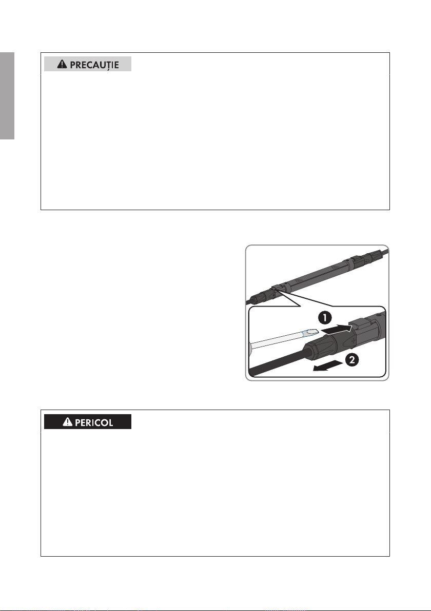
8 Întreţinerea conectorilor de siguranţe
SMA Solar Technology AG
ROMÂNĂ
Pericol de arsuri din cauza conectorilor de siguranţe fiebinţi
În timpul funcţionării conectorii de siguranţe se încing până la 90°C. Atingerea conectorilor de
siguranţe poate duce la arsuri.
• Nu atingeţi conectorii de siguranţe decât cu echipament de protecţie adecvat.
• Depuneţi conectorii de siguranţe demontaţi, încă fierbinţi, aşa încât să excludeţi pericolul de
atingere accidentală.
• Montaţi conectorii de siguranţe aşa încât circulaţia aerului să fie posibilă în jurul acestora.
Răcirea conectorilor de siguranţe datorită aerului ambiental este absolut necesară.
• Montaţi conectorii de siguranţe aşa încât să excludeţi pericolul de atingere accidentală.
Când faceţi acest lucru, aveţi grijă să nu împiedicaţi circulaţia aerului în jurul conectorilor de
siguranţe.
Cum se procedează:
1. Deconectaţi subdistribuitorul DC (vezi instrucţiunile subdistribuitorului DC).
2. Introduceţi o şurubelniţă sau o agrafă (lăţimea
lamei:3,5mm) într-una din fantele laterale ale
conectorului fişabil DC şi scoateţi conectorul de
siguranţă în poziţie dreaptă. Când faceţi acest
lucru, nu trageţi de cablurile de şiruri.
8 Întreţinerea conectorilor de siguranţe
Pericol de moarte prin arc electric
La cuplarea sau decuplarea conectorilor fişabili DC sau a conectorilor de siguranţe sub sarcină,
precum şi în cazul inversării polilor la racordarea conectorilor fişabili DC se poate forma arc
electric. Dacă intervine fenomenul de arc electric, urmările pot fi decesul sau vătămările
corporale grave.
• Înainte de conectare, asiguraţi-vă de polaritatea corectă a şirurilor fotovoltaice.
• Cuplaţi sau decuplaţi conectorii fişabili DC sau conectorii de siguranţe numai după
scoaterea de sub sarcină.
• Deconectaţi subdistribuitorul DC (vezi instrucţiunile subdistribuitorului DC).
• Purtaţi echipament individual de protecţie adecvat.
Instrucţiuni de instalareInlineFuse-IA-xx-1066
Page 67

SMA Solar Technology AG
9 Date tehnice
Deteriorarea conectorilor de siguranţe prin utilizarea de sprayuri de curăţat contacte
sau de alte produse de curăţare
Anumite sprayuri de curăţat contacte sau alte produse de curăţare pot conţine substanţe care
dizolvă plasticul din conectorii de siguranţe.
• Nu curăţaţi conectorii de siguranţe cu sprayuri de curăţat contacte sau cu alte produse de
curăţare.
Cum se procedează:
1. Deconectaţi subdistribuitorul DC (vezi instrucţiunile subdistribuitorului DC).
2. Verificaţi dacă conectorii de siguranţe prezintă deteriorări.
În cazul în care conectorii de siguranţe prezintă deteriorări, contactaţi service-ul (vezi
capitolul10, pagina67).
9 Date tehnice
Siguranţă de şir
Intensitatea nominală a curentului în siguranţele
de şiruri
Caracteristică de siguranţă gPV
Mărimea conectorului de siguranţă 1.000V
Mărimea conectorului de siguranţă 1.500V
Curent maxim dimensionat per siguranţă 0,55 x I
Interval de temperatură ‒40°C … +55°C
Înălţime maximă peste nivelul mării** 4.000m
* 20A, 25A, 30A cu distanţier
** La o înălţime de instalare de peste 2.000m, atunci când dimensionaţi siguranţele trebuie avut în vedere
un factor de reducţie de 0,5% pentru fiecare 100m înălţime (vezi Informaţii tehnice „IFCON Inline-FuseConnector-Set16”).
6ADC / 8ADC / 10ADC /12ADC / 15ADC /
20ADC / 25ADC / 30A
DC
DC
26,4mm x 175,0mm
26,4mm x 220,0mm
30,0mm x 220,0mm*
siguranţă
nom
DC
ROMÂNĂ
10 Contact
Date de contact găsiţi la adresa www.SMA-Solar.com.
Instrucţiuni de instalare 67InlineFuse-IA-xx-10
Page 68

ΕΛΛΗΝΙΚΑ
Πίνακας περιεχομένων
SMA Solar Technology AG
Πίνακας περιεχομένων
1 Υποδείξεις για αυτό το έγγραφο ............................................. 69
1.1 Τομέας ισχύος.................................................................................... 69
1.2 Σε ποιους απευθύνεται...................................................................... 69
1.3 Περισσότερες πληροφορίες.............................................................. 69
1.4 Σύμβολα............................................................................................. 69
1.5 Ονοματολογία ................................................................................... 70
2 Ασφάλεια................................................................................... 70
2.1 Προβλεπόμενη χρήση ....................................................................... 70
2.2 Υποδείξεις ασφαλείας....................................................................... 71
3 Παραδιδόμενος εξοπλισμός.................................................... 72
4 Σχεδιασμός των ασφαλειών..................................................... 73
5 Απαιτήσεις για το σημείο εγκατάστασης................................. 74
6 Τοποθέτηση βυσμάτων ασφαλειών.......................................... 74
7 Αφαίρεση βυσμάτων ασφαλειών ............................................. 75
8 Συντήρηση βυσμάτων ασφαλειών........................................... 76
9 Τεχνικά χαρακτηριστικά ........................................................... 77
10 Επικοινωνία ............................................................................... 77
Οδηγίες εγκατάστασηςInlineFuse-IA-xx-1068
Page 69

SMA Solar Technology AG
1 Υποδείξεις για αυτό το έγγραφο
1 Υποδείξεις για αυτό το έγγραφο
1.1 Τομέας ισχύος
Αυτό το έγγραφο ισχύει για τους ακόλουθους τύπους προϊόντων (σετ βυσμάτων ασφαλειών):
Τύπος προϊόντος
• IFCON16S0610
• IFCON16S0810
• IFCON16S1010
• IFCON16S1210
• IFCON16S1510
• IFCON16S2010
• IFCON16S2510
• IFCON16S3010
1.2 Σε ποιους απευθύνεται
Οι εργασίες που περιγράφονται στο παρόν έγγραφο, επιτρέπεται να εκτελούνται αποκλειστικά από
ειδικευμένο προσωπικό. Το ειδικευμένο προσωπικό πρέπει να διαθέτει τα ακόλουθα προσόντα:
• Γνώση του τρόπου λειτουργίας και της λειτουργίας του προϊόντος
• Κατάρτιση στην αντιμετώπιση κινδύνων κατά την εγκατάσταση και το χειρισμό ηλεκτρικών
συσκευών και εγκαταστάσεων
• Εκπαίδευση για την εγκατάσταση και τη θέση σε λειτουργία ηλεκτρικών συσκευών και
εγκαταστάσεων
• Γνώση των σχετικών προτύπων και οδηγιών
• Γνώση και τήρηση του παρόντος εγχειριδίου οδηγιών με όλες τις υποδείξεις ασφαλείας
• IFCON16S0615
• IFCON16S0815
• IFCON16S1015
• IFCON16S1215
• IFCON16S1515
• IFCON16S2015
• IFCON16S2515
• IFCON16S3015
ΕΛΛΗΝΙΚΑ
1.3 Περισσότερες πληροφορίες
Σύνδεσμοι προς περισσότερες πληροφορίες παρέχονται στην ιστοσελίδα www.SMA-Solar.com:
Τίτλος εγγράφου και περιεχόμενο
εγγράφου
«"IFCON Inline-Fuse-Connector-Set16"»
Πληροφορίες για τον σχεδιασμό, τις
δυνατότητες σύνδεσης και τα αξεσουάρ
Είδος εγγράφου
Τεχνικές πληροφορίες
1.4 Σύμβολα
Σύμβολο Επεξήγηση
Προειδοποιητική υπόδειξη, η παράβλεψη της
οποίας έχει ως άμεσο αποτέλεσμα το θάνατο ή
βαρύ τραυματισμό
Οδηγίες εγκατάστασης 69InlineFuse-IA-xx-10
Page 70

ΕΛΛΗΝΙΚΑ
2 Ασφάλεια
Σύμβολο Επεξήγηση
Προειδοποιητική υπόδειξη, η παράβλεψη της
οποίας μπορεί να προκαλέσει θάνατο ή σοβαρό
τραυματισμό
Προειδοποιητική υπόδειξη, η παράβλεψη της
οποίας μπορεί να έχει ως αποτέλεσμα ελαφρύ ή
μέτριο τραυματισμό
Προειδοποιητική υπόδειξη, η παράβλεψη της
οποίας μπορεί να προκαλέσει υλικές ζημιές
Κεφάλαιο, όπου περιγράφονται εργασίες, οι
οποίες επιτρέπεται να εκτελούνται αποκλειστικά
από ειδικευμένο προσωπικό
Πληροφορίες, οι οποίες είναι σημαντικές για ένα
συγκεκριμένο θέμα ή στόχο, αλλά δεν σχετίζονται
με την ασφάλεια
Προϋπόθεση που πρέπει να ισχύει για ένα
συγκεκριμένο στόχο
Επιθυμητό αποτέλεσμα
Πιθανό πρόβλημα
1.5 Ονοματολογία
SMA Solar Technology AG
Πλήρης ονομασία Ονομασία στο παρόν έγγραφο
Σετ βυσμάτων ασφαλειών • Σετ βυσμάτων ασφαλειών
• Προϊόν
SMA String-Monitor • SMA String-Monitor
• Υποδιανομέας DC
2 Ασφάλεια
2.1 Προβλεπόμενη χρήση
Το βύσμα ασφαλειών είναι μια ασφάλεια στοιχειοσειράς και προστατεύει της Φ/Β στοιχειοσειρές
από ανάστροφα ρεύματα. Το βύσμα ασφαλειών συνδέεται σε βύσματα σύνδεσης DC ή σε
αντάπτορες Y από το κουμπωτό σύστημα Sunclix.
Όλες οι εργασίες στο προϊόν επιτρέπεται να πραγματοποιούνται μόνο με κατάλληλα εργαλεία.
Προσέξτε τις υποδείξεις του κατασκευαστή του προϊόντος.
Χρησιμοποιείτε το προϊόν αποκλειστικά σύμφωνα με τις υποδείξεις των συνοδευτικών εγγράφων
τεκμηρίωσης και σύμφωνα με τα πρότυπα και τις οδηγίες που ισχύουν στον τόπο της
εγκατάστασης. Κάθε άλλη χρήση μπορεί να προκαλέσει σωματικές βλάβες ή υλικές ζημιές.
Οδηγίες εγκατάστασηςInlineFuse-IA-xx-1070
Page 71

SMA Solar Technology AG
2 Ασφάλεια
Επεμβάσεις στο προϊόν, π.χ. τροποποιήσεις και μετατροπές, επιτρέπονται μόνο με ρητή έγγραφη
άδεια της SMA Solar Technology AG. Οι μη εξουσιοδοτημένες επεμβάσεις επιφέρουν απώλεια των
αξιώσεων εγγύησης καθώς και κατά κανόνα απώλεια της έγκρισης λειτουργίας. Αποκλείεται η
ευθύνη της SMA Solar Technology AG για ζημιές που οφείλονται σε τέτοιου είδους επεμβάσεις.
Κάθε χρήση του προϊόντος διαφορετική από αυτή που περιγράφεται στην προβλεπόμενη χρήση
θεωρείται ως μη προβλεπόμενη.
Τα συνοδευτικά έγγραφα τεκμηρίωσης αποτελούν αναπόσπαστο μέρος του προϊόντος. Τα
έγγραφα τεκμηρίωσης πρέπει να διαβάζονται, να λαμβάνονται υπόψη και να φυλάσσονται σε ανά
πάσα στιγμή προσβάσιμο μέρος.
2.2 Υποδείξεις ασφαλείας
Επικίνδυνη για τη ζωή ηλεκτροπληξία από τάση
Στα υπό τάση εξαρτήματα του υποδιανομέα DC επικρατούν υψηλές τάσεις. Η επαφή με
εξαρτήματα υπό τάση έχει ως αποτέλεσμα τον θάνατο ή σοβαρούς τραυματισμούς από
ηλεκτροπληξία.
• Κατά την εκτέλεση οποιασδήποτε εργασίας χρησιμοποιείτε κατάλληλα μέσα ατομικής
προστασίας.
• Μην ακουμπάτε εξαρτήματα που φέρουν τάση.
• Εάν δεν είναι απόλυτα αναγκαίο να υπάρχει τάση, απομονώστε πριν από κάθε εργασία
στον υποδιανομέα DC από την τάση όλους τους διανομείς DC και απομονώστε τον
μετατροπέα από την τάση στην πλευρά DC (βλ. οδηγίες του υποδιανομέα DC και του
μετατροπέα).
Κίνδυνος-θάνατος από υψηλές τάσεις σε αγωγούς DC
Κατά την πρόσπτωση ηλιακής ακτινοβολίας, η Φ/Β γεννήτρια παράγει επικίνδυνη συνεχή τάση,
η οποία επικρατεί στους αγωγούς DC. Η επαφή με αγωγούς DC έχει ως αποτέλεσμα τον θάνατο
ή σοβαρούς τραυματισμούς από ηλεκτροπληξία.
• Καλύψτε τις φωτοβολταϊκές μονάδες.
• Μην αγγίζετε τους αγωγούς DC.
ΕΛΛΗΝΙΚΑ
Οδηγίες εγκατάστασης 71InlineFuse-IA-xx-10
Page 72

ΕΛΛΗΝΙΚΑ
3 Παραδιδόμενος εξοπλισμός
Κίνδυνος-θάνατος από βολταϊκό τόξο
Κατά τη σύνδεση ή αποσύνδεση των βυσμάτων σύνδεσης DC ή των βυσμάτων ασφαλειών υπό
φορτίο και σε περίπτωση σύνδεσης των βυσμάτων σύνδεσης DC με αντιμετάθεση πόλων μπορεί
να δημιουργηθεί βολταϊκό τόξο. Σε περίπτωση βολταϊκού τόξου οι συνέπειες είναι σοβαροί
τραυματισμοί ή θάνατος.
• Εξασφαλίστε τη σωστή πολικότητα των Φ/Β στοιχειοσειρών πριν από τη σύνδεση.
• Συνδέετε ή αποσυνδέετε τα βύσματα σύνδεσης DC ή τα βύσματα ασφαλειών μόνο όταν
βρίσκονται σε κατάσταση χωρίς φορτίο.
• Απομονώστε από την τάση τον υποδιανομέα DC (βλ. οδηγίες του υποδιανομέα DC).
• Χρησιμοποιείτε κατάλληλα μέσα ατομικής προστασίας.
Πρόκληση ζημιών στη Φ/Β εγκατάσταση λόγω εσφαλμένης διαστασιολόγησης των
ασφαλειών
Εάν οι ασφάλειες δεν έχουν σχεδιαστεί σωστά, οι Φ/Β μονάδες μπορούν να καταστραφούν από
υψηλά ανάστροφα ρεύματα.
• Κατά την επιλογή των ασφαλειών λαμβάνετε υπόψη τις μέγιστες τιμές ρεύματος για το
προϊόν.
SMA Solar Technology AG
Πρόκληση ζημιών στα βύσματα σύνδεσης DC από τη χρήση καθαριστικών επαφής ή
άλλων καθαριστικών.
Μερικά καθαριστικά επαφής ή άλλα καθαριστικά μπορεί να περιέχουν ουσίες που
αποσυνθέτουν το πλαστικό των βυσμάτων σύνδεσης DC.
• Μην χρησιμοποιείτε καθαριστικά επαφής ή άλλα καθαριστικά για τα βύσματα σύνδεσης
DC.
3 Παραδιδόμενος εξοπλισμός
Ελέγξτε τον εξοπλισμό που παραλάβατε ως προς την πληρότητά του καθώς και για εμφανείς
εξωτερικές ζημιές. Σε περίπτωση που ο παραδιδόμενος εξοπλισμός δεν είναι πλήρης ή σε
περίπτωση ζημιών επικοινωνήστε με τον προμηθευτή σας.
Οδηγίες εγκατάστασηςInlineFuse-IA-xx-1072
Page 73

SMA Solar Technology AG
Εικόνα 8 : Στοιχεία του παραδιδόμενου εξοπλισμού
Θέση Αριθμός Ονομασία
A 16 Βύσμα ασφαλειών
B 1 Οδηγίες εγκατάστασης
4 Σχεδιασμός των ασφαλειών
4 Σχεδιασμός των ασφαλειών
Τα βύσματα ασφαλειών μπορούν να χρησιμοποιηθούν χωρίς πρόσθετο derating σε θερμοκρασίες
περιβάλλοντος έως +55°C σε δέσμη κάτω από το SMA String-Monitor. Κατά την επιλογή των
σωστών ονομαστικών τιμών των ασφαλειών (l
0,55 στο ρεύμα βραχυκύκλωσης της συνδεδεμένης Φ/Β γεννήτριας σε πρότυπες συνθήκες
ελέγχου (ISC_STC).
Ισχύει:
ISC_STC ≤ I
x συντελεστής μείωσης ή I
ονομ
Ο συντελεστής μείωσης 0,55 ισχύει μέχρι μια μέγιστη ακτινοβολία 1.200W/m2 (μέση τιμή ωρών
της οριζόντιας ολικής ακτινοβολίας). Εάν αναμένεται ακόμη υψηλότερη ακτινοβολία, πρέπει να
προσαρμόζεται ο συντελεστής μείωσης αντίστοιχα γραμμικά προς τα κάτω, με αναφορά τα
1.200W/m2.
Σχεδιασμός των ασφαλειών σε υψόμετρο εγκατάστασης έως και 2.000m
Κατά τον σχεδιασμό της ασφάλειας πρέπει να λαμβάνονται υπόψη οι ακόλουθοι παράγοντες για
υψόμετρο έως και 2.000m:
• Θερμοκρασία περιβάλλοντος: ‒40°C έως +55°C
• Μέγιστο ονομαστικό ρεύμα ανά ασφάλεια: 0,55 x I
• Μέγιστο ονομαστικό ρεύμα ανά κανάλι μέτρησης της συσκευής
• Μέγιστο ρεύμα για τη συσκευή
Κατά τον σχεδιασμό πρέπει να λαμβάνεται υπόψη η αντοχή των φωτοβολταϊκών μονάδων σε
ανάστροφα ρεύματα.
Πρόσθετος συντελεστής μείωσης σε υψόμετρο εγκατάστασης μεγαλύτερο από
2.000m
Σε υψόμετρο εγκατάστασης πάνω από 2.000m πρέπει να συνυπολογίζεται για κάθε επιπλέον
100m υψομέτρου ένας πρόσθετος συντελεστής μείωσης 0,5% κατά τον σχεδιασμό των
ασφαλειών.
Περισσότερες πληροφορίες παρέχονται στις τεχνικές πληροφορίες «"IFCON Inline-Fuse-ConnectorSet16"».
) πρέπει να χρησιμοποιείται ο συντελεστής μείωσης
ονομ
≥ ISC_STC / συντελεστής μείωσης
ονομ
ονομ ασφ.
ΕΛΛΗΝΙΚΑ
Οδηγίες εγκατάστασης 73InlineFuse-IA-xx-10
Page 74

5 Απαιτήσεις για το σημείο εγκατάστασης
SMA Solar Technology AG
5 Απαιτήσεις για το σημείο εγκατάστασης
☐ Θερμοκρασία περιβάλλοντος: ‒40°C έως +55°C
☐ Τα βύσματα ασφαλειών δεν επιτρέπεται να έρχονται σε επαφή με αντικείμενα, που
αναπτύσσουν θερμοκρασίες άνω των +55°C.
6 Τοποθέτηση βυσμάτων ασφαλειών
ΕΛΛΗΝΙΚΑ
Κίνδυνος-θάνατος από βολταϊκό τόξο
Κατά τη σύνδεση ή αποσύνδεση των βυσμάτων σύνδεσης DC ή των βυσμάτων ασφαλειών υπό
φορτίο και σε περίπτωση σύνδεσης των βυσμάτων σύνδεσης DC με αντιμετάθεση πόλων μπορεί
να δημιουργηθεί βολταϊκό τόξο. Σε περίπτωση βολταϊκού τόξου οι συνέπειες είναι σοβαροί
τραυματισμοί ή θάνατος.
• Εξασφαλίστε τη σωστή πολικότητα των Φ/Β στοιχειοσειρών πριν από τη σύνδεση.
• Συνδέετε ή αποσυνδέετε τα βύσματα σύνδεσης DC ή τα βύσματα ασφαλειών μόνο όταν
βρίσκονται σε κατάσταση χωρίς φορτίο.
• Απομονώστε από την τάση τον υποδιανομέα DC (βλ. οδηγίες του υποδιανομέα DC).
• Χρησιμοποιείτε κατάλληλα μέσα ατομικής προστασίας.
Προϋποθέσεις:
☐ Τα θετικά καλώδια σύνδεσης των Φ/Β μονάδων πρέπει να φέρουν τα θετικά βύσματα
σύνδεσης DC (για πληροφορίες σχετικές με τη συναρμολόγηση των βυσμάτων σύνδεσης DC
βλ. οδηγίες εγκατάστασης των βυσμάτων σύνδεσης DC).
☐ Τα αρνητικά καλώδια σύνδεσης των Φ/Β μονάδων πρέπει να φέρουν τα αρνητικά βύσματα
σύνδεσης DC (για πληροφορίες σχετικές με τη συναρμολόγηση των βυσμάτων σύνδεσης DC
βλ. οδηγίες εγκατάστασης των βυσμάτων σύνδεσης DC).
Διαδικασία:
1. Απομονώστε από την τάση τον υποδιανομέα DC (βλ. οδηγίες του υποδιανομέα DC).
2. Με κατάλληλο όργανο μετρήσεων μετρήστε την τάση σε ένα συναρμολογημένο βύσμα
σύνδεσης DC ενός καλωδίου σύνδεση των Φ/Β μονάδων.
3. Για αυτό το βύσμα σύνδεσης DC επιλέξτε ένα βύσμα ασφαλειών με κατάλληλη ονομαστική
ένταση.
4. Τοποθετήστε το κατάλληλο άκρο του βύσματος ασφαλειών στο συναρμολογημένο βύσμα
σύνδεσης DC. Το βύσμα ασφαλειών κουμπώνει με χαρακτηριστικό ήχο.
5. Τοποθετήστε το άλλο άκρο του βύσματος ασφαλειών στο βύσμα σύνδεσης DC του
υποδιανομέα DC. Το βύσμα ασφαλειών κουμπώνει με χαρακτηριστικό ήχο.
6. Βεβαιωθείτε ότι το βύσμα σύνδεσης DC εφαρμόζει σωστά.
Οδηγίες εγκατάστασηςInlineFuse-IA-xx-1074
Page 75

SMA Solar Technology AG
7. Στερεώστε το καλώδιο στοιχειοσειράς στη ράγα στερέωσης καλωδίων (βλ. εγχειρίδιο χειρισμού
του υποδιανομέα DC). Προσέξτε τη διάταξη και τη στερέωση των καλωδίων στοιχειοσειράς,
ώστε να μην υπερθερμαίνονται τα βύσματα ασφαλειών.
8. Πραγματοποιήστε τα βήματα για κάθε βύσμα σύνδεσης DC των καλωδίων σύνδεσης των Φ/Β
μονάδων.
7 Αφαίρεση βυσμάτων ασφαλειών
7 Αφαίρεση βυσμάτων ασφαλειών
Κίνδυνος-θάνατος από βολταϊκό τόξο
Κατά τη σύνδεση ή αποσύνδεση των βυσμάτων σύνδεσης DC ή των βυσμάτων ασφαλειών υπό
φορτίο και σε περίπτωση σύνδεσης των βυσμάτων σύνδεσης DC με αντιμετάθεση πόλων μπορεί
να δημιουργηθεί βολταϊκό τόξο. Σε περίπτωση βολταϊκού τόξου οι συνέπειες είναι σοβαροί
τραυματισμοί ή θάνατος.
• Εξασφαλίστε τη σωστή πολικότητα των Φ/Β στοιχειοσειρών πριν από τη σύνδεση.
• Συνδέετε ή αποσυνδέετε τα βύσματα σύνδεσης DC ή τα βύσματα ασφαλειών μόνο όταν
βρίσκονται σε κατάσταση χωρίς φορτίο.
• Απομονώστε από την τάση τον υποδιανομέα DC (βλ. οδηγίες του υποδιανομέα DC).
• Χρησιμοποιείτε κατάλληλα μέσα ατομικής προστασίας.
Κίνδυνος εγκαύματος από θερμά βύσματα ασφαλειών
Στα βύσματα ασφαλειών αναπτύσσονται κατά τη λειτουργία θερμοκρασίες έως και 90°C. Η
επαφή με τα βύσματα ασφαλειών μπορεί να προκαλέσει εγκαύματα.
• Ακουμπάτε τα βύσματα ασφαλειών μόνο με κατάλληλο εξοπλισμό προστασίας.
• Αποθέτετε τα ζεστά, αποσυνδεδεμένα βύσματα ασφαλειών έτσι ώστε ώστε να μην υπάρχει
πιθανότητα ακούσιας επαφής.
• Τοποθετείτε τα βύσματα ασφαλειών έτσι ώστε να είναι δυνατή η κυκλοφορία του αέρα γύρω
από τα βύσματα ασφαλειών. Μια ψύξη των βυσμάτων ασφαλειών από τον αέρα του
περιβάλλοντος είναι απολύτως αναγκαία.
• Τοποθετήστε τα βύσματα ασφαλειών έτσι, ώστε να μην υπάρχει πιθανότητα ακούσιας
επαφής. Δεν επιτρέπεται να εμποδίζεται η κυκλοφορία του αέρα γύρω από τα βύσματα
ασφαλειών.
ΕΛΛΗΝΙΚΑ
Οδηγίες εγκατάστασης 75InlineFuse-IA-xx-10
Page 76
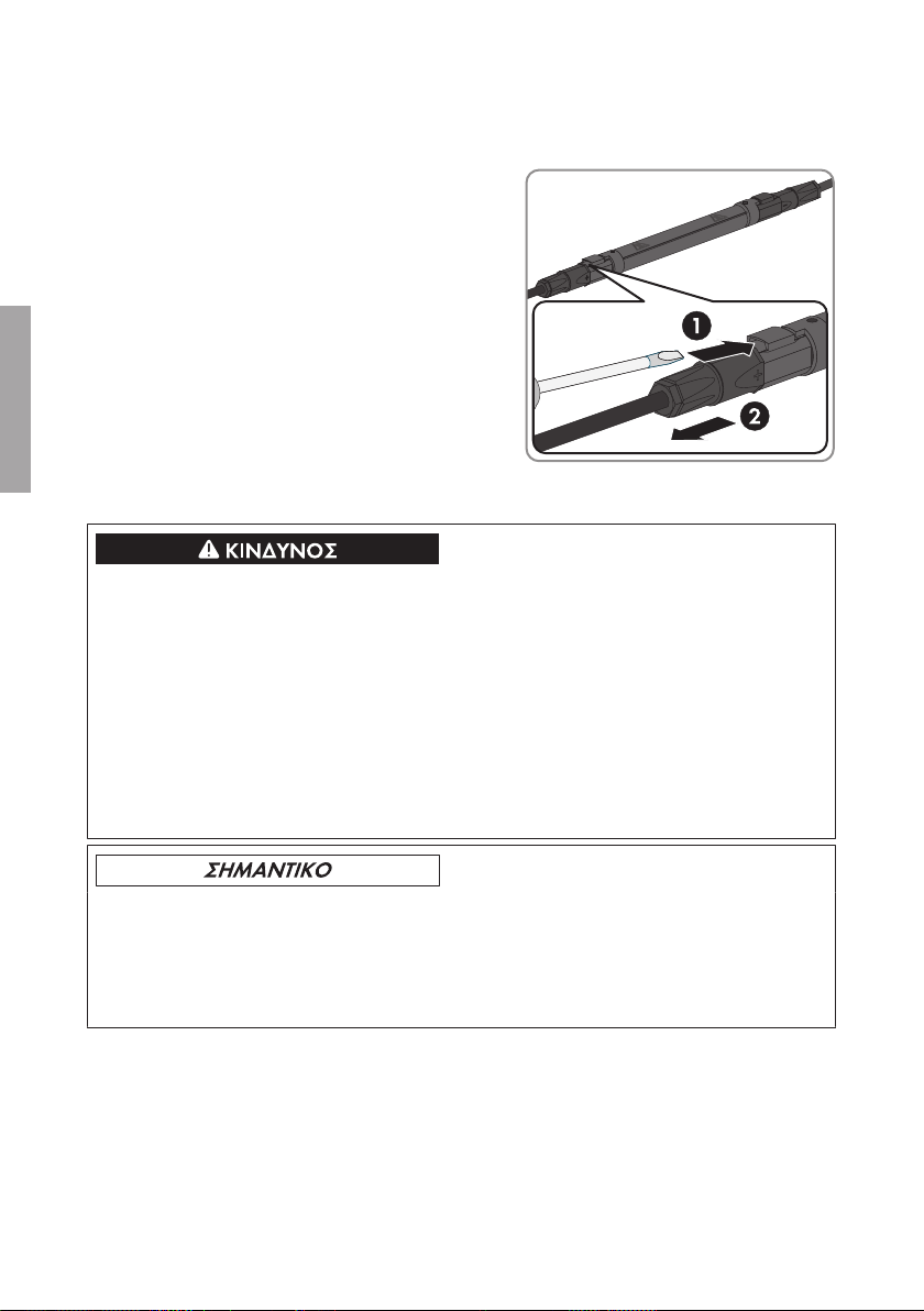
ΕΛΛΗΝΙΚΑ
8 Συντήρηση βυσμάτων ασφαλειών
Διαδικασία:
1. Απομονώστε από την τάση τον υποδιανομέα DC (βλ. οδηγίες του υποδιανομέα DC).
2. Για την αφαίρεση εισάγετε ένα κατσαβίδι ή ένα
κατσαβίδι κεκαμμένης λάμας (πλάτος μύτης:
3,5mm) σε μία από τις πλευρικές σχισμές του
βύσματος σύνδεσης DC και αφαιρέστε το
βύσμα ασφαλειών τραβώντας το ευθύγραμμα.
Κατά τη διαδικασία αυτή μην τραβάτε τα
καλώδια στοιχειοσειράς.
SMA Solar Technology AG
8 Συντήρηση βυσμάτων ασφαλειών
Κίνδυνος-θάνατος από βολταϊκό τόξο
Κατά τη σύνδεση ή αποσύνδεση των βυσμάτων σύνδεσης DC ή των βυσμάτων ασφαλειών υπό
φορτίο και σε περίπτωση σύνδεσης των βυσμάτων σύνδεσης DC με αντιμετάθεση πόλων μπορεί
να δημιουργηθεί βολταϊκό τόξο. Σε περίπτωση βολταϊκού τόξου οι συνέπειες είναι σοβαροί
τραυματισμοί ή θάνατος.
• Εξασφαλίστε τη σωστή πολικότητα των Φ/Β στοιχειοσειρών πριν από τη σύνδεση.
• Συνδέετε ή αποσυνδέετε τα βύσματα σύνδεσης DC ή τα βύσματα ασφαλειών μόνο όταν
βρίσκονται σε κατάσταση χωρίς φορτίο.
• Απομονώστε από την τάση τον υποδιανομέα DC (βλ. οδηγίες του υποδιανομέα DC).
• Χρησιμοποιείτε κατάλληλα μέσα ατομικής προστασίας.
Πρόκληση ζημιών στα βύσματα ασφαλειών από τη χρήση καθαριστικών επαφής ή
άλλων καθαριστικών.
Μερικά καθαριστικά επαφής ή άλλα καθαριστικά μπορεί να περιέχουν ουσίες που
αποσυνθέτουν το πλαστικό των βυσμάτων ασφαλειών.
• Μην χρησιμοποιείτε καθαριστικά επαφής ή άλλα καθαριστικά για τα βύσματα ασφαλειών.
Διαδικασία:
1. Απομονώστε από την τάση τον υποδιανομέα DC (βλ. οδηγίες του υποδιανομέα DC).
2. Ελέγξτε εάν έχουν παραμορφωθεί τα βύσματα ασφαλειών.
Εάν έχουν παραμορφωθεί τα βύσματα ασφαλειών, επικοινωνήστε με το σέρβις (βλ.
κεφάλαιο10, σελίδα77).
Οδηγίες εγκατάστασηςInlineFuse-IA-xx-1076
Page 77

SMA Solar Technology AG
9 Τεχνικά χαρακτηριστικά
9 Τεχνικά χαρακτηριστικά
Ασφάλεια στοιχειοσειράς
Ονομαστική ένταση ρεύματος των ασφαλειών
στοιχειοσειράς
6ADC / 8ADC / 10ADC /12ADC / 15ADC /
20ADC / 25ADC / 30A
DC
Χαρακτηριστικά ασφαλειών gPV
Μέγεθος των βυσμάτων ασφαλειών 1.000V
Μέγεθος των βυσμάτων ασφαλειών 1.500V
DC
DC
26,4mm x 175,0mm
26,4mm x 220,0mm
30,0mm x 220,0mm*
Μέγιστο ονομαστικό ρεύμα ανά ασφάλεια 0,55 x I
ασφάλειας
ονομ
Εύρος θερμοκρασίας ‒40°C έως +55°C
Μέγιστο υψόμετρο από τη ΜΣΘ** 4.000m
* 20A, 25A, 30A με αποστάτη
** Σε υψόμετρο εγκατάστασης πάνω από 2.000m πρέπει να συνυπολογίζεται για κάθε επιπλέον 100m
υψομέτρου ένας πρόσθετος συντελεστής μείωσης 0,5% κατά τον σχεδιασμό των ασφαλειών (βλέπε
τεχνικές πληροφορίες «"IFCON Inline-Fuse-Connector-Set16"»).
10 Επικοινωνία
Για στοιχεία επικοινωνίας επισκεφθείτε τη διεύθυνση www.SMA-Solar.com.
ΕΛΛΗΝΙΚΑ
Οδηγίες εγκατάστασης 77InlineFuse-IA-xx-10
Page 78

목차
SMA Solar Technology AG
목차
1 본 문서에 대한 정보................................................................. 79
1.1 적용 범위.......................................................................................... 79
1.2 대상 그룹.......................................................................................... 79
1.3 부가 정보.......................................................................................... 79
1.4 기호.................................................................................................... 79
1.5 명명법 ............................................................................................... 80
2 안전............................................................................................ 80
2.1 사용 용도.......................................................................................... 80
2.2 안전 정보.......................................................................................... 81
3 인도 범위................................................................................... 82
한국어
4 퓨즈 정격................................................................................... 82
5 설치 위치 요구사항.................................................................. 83
6 인라인 퓨즈 커넥터 장착......................................................... 83
7 인라인 퓨즈 커넥터 분해......................................................... 84
8 인라인 퓨즈 커넥터의 유지 보수............................................ 85
9 기술 데이터............................................................................... 86
10 문의처........................................................................................ 86
설치 매뉴얼InlineFuse-IA-xx-1078
Page 79

SMA Solar Technology AG
1 본 문서에 대한 정보
1 본 문서에 대한 정보
1.1 적용 범위
이 문서는 다음 제품 유형 (인라인 퓨즈 커넥터 세트)용입니다.
제품 유형
• IFCON16S0610
• IFCON16S0810
• IFCON16S1010
• IFCON16S1210
• IFCON16S1510
• IFCON16S2010
• IFCON16S2510
• IFCON16S3010
1.2 대상 그룹
이 문서에서 설명하는 작업은 적격한 기술자만 수행할 수 있습니다. 적격한 기술자가
보유해야 하는 기술:
• 제품의 작동 및 조작 방법에 대한 지식
• 전기 장치와 시스템의 설치 및 사용에 관련된 위험을 처리하는 방법에 대한 교육
이수
• 전기 장치 및 시스템의 설치와 시운전에 대한 교육 이수
• 적용 가능한 표준 및 지침에 관한 지식
• 본 매뉴얼과 모든 안전 주의 사항에 대한 지식 및 준수
• IFCON16S0615
• IFCON16S0815
• IFCON16S1015
• IFCON16S1215
• IFCON16S1515
• IFCON16S2015
• IFCON16S2515
• IFCON16S3015
한국어
1.3 부가 정보
부가 정보 링크는 www.SMA-Solar.com에 있습니다.
문서 제목 및 목차 문서 유형
"IFCON 인라인 퓨즈 커넥터 세트 16"
정격, 회로 옵션 및 액세서리 관련 정보
기술 정보
1.4 기호
기호 설명
지시를 준수하지 않을 경우 사망에 이르거나
심각한 부상을 입는 위험한 상황을 나타냅니
다.
지시를 준수하지 않을 경우 사망에 이르거나
심각한 부상을 입을 수 있는 위험한 상황을
나타냅니다.
설치 매뉴얼 79InlineFuse-IA-xx-10
Page 80

2 안전
기호 설명
지시를 준수하지 않을 경우 중경상을 입을 수
있는 위험한 상황을 나타냅니다.
지시를 준수하지 않을 경우 재산 손실이 발생
할 수 있는 상황을 나타냅니다.
적격한 기술자만 수행해야 하는 작업에 대해
설명된 섹션
특정 주제나 목적과 관련하여 중요하지만 안
전과는 관련이 없는 정보입니다.
특정한 목적을 충족하기 위한 요구조건을 나
타냅니다.
원하는 결과를 나타냅니다.
발생할 수 있는 문제를 나타냅니다.
SMA Solar Technology AG
한국어
1.5 명명법
전체 명칭 본 문서에서의 명칭
인라인 퓨즈 커넥터 세트 • 인라인 퓨즈 커넥터 세트
• 제품
SMA String-Monitor • SMA String-Monitor
• DC 하위 분배 장치
2 안전
2.1 사용 용도
인라인 퓨즈 커넥터는 역전류로부터 스트링을 보호하는 스트링 퓨즈입니다. 인라인 퓨
즈 커넥터는 SUNCLIX 플러그인 시스템의 DC 커넥터 또는 Y 어댑터에 연결됩니다.
모든 제품 관련 작업은 적절한 공구를 사용하여 수행하십시오.
제품의 제조사 사양을 준수하십시오.
이 제품은 동봉된 문서의 정보 및 현지의 해당 표준과 지침에 준해서만 사용하십시오.
다른 방식으로 이용할 경우 부상이나 자산 손실이 발생할 수 있습니다.
변경이나 개조와 같은 제품 변경은 SMASolarTechnologyAG의 서면 승인 없이는 허용되
지 않습니다. 무단 개조 시 보증 및 보증 청구가 무효화되며 일반적으로 운전 허가가 무
효화됩니다. SMASolarTechnologyAG SMA 는 이러한 개조로 인해 발생하는 손상에 대
해 책임지지 않습니다.
규정에 따른 사용 섹션에 기술된 용도 이외의 모든 제품 사용은 적절하지 않은 사용으
로 간주됩니다.
동봉된 관련 문서는 이 제품의 일부입니다. 본 문서를 나중에 쉽게 찾아볼 수 있는 곳에
보관하고 기재된 모든 지침을 준수하십시오.
설치 매뉴얼InlineFuse-IA-xx-1080
Page 81

SMA Solar Technology AG
2 안전
2.2 안전 정보
감전으로 인한 생명의 위험
DC 하위 분배 장치에서 전기가 통하는 부품에는 고압이 흐릅니다. 전압이 흐르는 부
품을 만지면 감전으로 인해 사망 또는 심각한 부상을 초래할 수 있습니다.
• 제품에 대한 모든 작업 수행 시 적절한 개인 보호 장비를 착용하십시오.
• 전압이 흐르는 부품을 만지지 마십시오.
• 전압이 꼭 흘러야 하는 경우가 아니라면 DC 하위 분전반을 취급하기 전에 모든
DC 하위 분전반의 연결을 해제하고 DC 측의 인버터를 분리하십시오 (인버터 및
DC 하위 분전반의 매뉴얼 참조).
DC 컨덕터의 고압으로 인한 생명의 위험
PV 발전기는 직사 광선에 노출될 경우 DC 컨덕터에서 위험한 DC 전압을 생성할 수 있
습니다. 따라서 DC 컨덕터를 만지면 감전으로 인해 사망 또는 심각한 부상을 초래할
수 있습니다.
• PV 모듈을 커버로 보호하십시오.
• DC 컨덕터에 접촉하지 않도록 주의하십시오.
한국어
전기 아크로 인한 생명의 위험
부하 상태에서 DC 커넥터 또는 인라인 퓨즈 커넥터를 연결하거나 분리할 때 그리고
DC 커넥터의 역방향 극 연결 상태에서는 전기 아크가 발생할 수 있습니다. 전기 아크
는 사망 또는 심각한 부상을 초래할 수 있습니다.
• 연결하기 전에 스트링의 극성이 올바른지 확인하십시오.
• DC 커넥터 및 인라인 퓨즈 커넥터는 무부하 조건에서만 연결하거나 분리하십시
오.
• DC 하위 분전반을 분리합니다 (DC 하위 분전반 매뉴얼 참조).
• 적절한 개인 보호 장비를 착용하십시오.
잘못된 정격 퓨즈로 인한 PV 시스템 손상
퓨즈의 정격이 잘못된 경우 과도한 역전류로 인해 PV 모듈이 파손될 수 있습니다.
• 퓨즈의 정격을 정할 때 제품의 최대 전류 값을 준수하십시오.
설치 매뉴얼 81InlineFuse-IA-xx-10
Page 82

3 인도 범위
SMA Solar Technology AG
다른 세정제가 포함된 접점 클리너 사용으로 인한 DC 커넥터 손상
일부 접점 클리너 또는 기타 세정제에는 DC 커넥터의 플라스틱을 분해시키는 성분이
포함되어 있을 수 있습니다.
• DC 커넥터를 청소할 때 접점 클리너 또는 기타 세정액을 사용하지 마십시오.
3 인도 범위
인도 시 모든 부품이 다 포함되어 있으며 외부에 눈에 보이는 손상은 없는지 확인하십
시오. 인도 범위에 누락되거나 손상된 부품이 있는 경우 판매점에 문의하십시오.
한국어
그림 9 : 인도 시 포함되는 부품
위치 수량 명칭
A 16 인라인 퓨즈 커넥터
B 1 설치 매뉴얼
4 퓨즈 정격
인라인 퓨즈 커넥터는 최대 +55°C의 온도에서 추가적인 저하 없이 SMAString-Monitor
하단 번들에 사용할 수 있습니다. 적정 공칭 퓨즈 값(I
(ISC_STC)에서 연결된 PV 발전기의 단락 전류에 감소 계수 0.55를 고려해야 합니다.
다음이 적용됩니다.
ISC_STC ≤ I
x 감소 계수 또는 I
nom
≥ ISC_STC/감소 계수
nom
최대 일조량 1,200W/m2 (수평면 전방사선의 시간당 평균값)에 감소 계수 0.55가 적용
됩니다. 더 높은 일조량이 예상되더라도 감소 계수를 1,200W/m2에 기반하여 선형적으
로 낮춰서 교정해야 합니다.
2,000m 이하 고도 설치 시 퓨즈 정격
2,000m 이하 고도 설치 시 퓨즈 정격을 정할 때 다음 계수를 고려해야 합니다.
• 외기 온도: ‒40°C ~ +55°C
• 퓨즈당 최대 정격 전류: 0.55 x I
• 장치 측정 채널당 최대 정격 전류
• 장치의 최대 전류
퓨즈 정격을 지정할 때 PV 모듈의 역전류 저항을 고려해야 합니다.
nom fuse
)을 선택할 때 표준 테스트 조건
nom
설치 매뉴얼InlineFuse-IA-xx-1082
Page 83

SMA Solar Technology AG
5 설치 위치 요구사항
2,000m 이상 고도 설치 시 보충 감소 계수
2,000m 이상 고도 설치 시 퓨즈 정격을 정할 때는 100m당 0.5 %의 추가적인 감소 계수
를 고려해야 합니다.
자세한 정보는 기술 정보 "IFCON 인라인 퓨즈 커넥터 세트 16"을(를) 참조하십시오.
5 설치 위치 요구사항
☐ 외기 온도: ‒40°C ~ +55°C
☐ 인라인 퓨즈 커넥터는 온도가 +55°C를 초과하는 주변 물체에 접촉하지 않아야 합
니다.
6 인라인 퓨즈 커넥터 장착
전기 아크로 인한 생명의 위험
부하 상태에서 DC 커넥터 또는 인라인 퓨즈 커넥터를 연결하거나 분리할 때 그리고
DC 커넥터의 역방향 극 연결 상태에서는 전기 아크가 발생할 수 있습니다. 전기 아크
는 사망 또는 심각한 부상을 초래할 수 있습니다.
• 연결하기 전에 스트링의 극성이 올바른지 확인하십시오.
• DC 커넥터 및 인라인 퓨즈 커넥터는 무부하 조건에서만 연결하거나 분리하십시
오.
• DC 하위 분전반을 분리합니다 (DC 하위 분전반 매뉴얼 참조).
• 적절한 개인 보호 장비를 착용하십시오.
한국어
요구 사항:
☐ PV 모듈의 양극 연결 케이블에는 양극 DC 커넥터를 장착해야 합니다 (DC 커넥터 조
립에 대해서는 DC 커넥터 설치 매뉴얼 참조).
☐ PV 모듈의 음극 연결 케이블에는 음극 DC 커넥터를 장착해야 합니다 (DC 커넥터 조
립에 대해서는 DC 커넥터 설치 매뉴얼 참조).
절차:
1. DC 하위 분전반을 분리합니다 (DC 하위 분전반 매뉴얼 참조).
2. 적절한 측정 장치를 사용하여 PV 모듈 연결 케이블의 조립된 DC 커넥터 전압을 측
정합니다.
3. 이 DC 커넥터에 적절한 공칭 전기 전류 강도를 가지는 인라인 퓨즈 커넥터를 선택
하십시오.
4. 인라인 퓨즈 커넥터의 적절한 끝부분을 조립된 DC 커넥터에 연결합니다. 인라인
퓨즈 커넥터가 제자리에 걸립니다.
5. 인라인 퓨즈 커넥터의 다른 쪽 끝을 DC 하위 분전반의 DC 커넥터에 삽입합니다. 인
라인 퓨즈 커넥터가 제자리에 걸립니다.
6. DC 커넥터에 제자리에 잘 고정되었는지 확인합니다.
설치 매뉴얼 83InlineFuse-IA-xx-10
Page 84

한국어
7 인라인 퓨즈 커넥터 분해
7. 스트링 케이블을 케이블 지지 레일에 고정합니다 (DC 하위 분전반의 운영 매뉴얼
참조). 인라인 퓨즈 커넥터의 과열을 방지하기 위해 스트링 케이블의 배치와 고정
을 준수하십시오.
8. PV 모듈 연결 케이블의 각 DC 커넥터에 대해 단계를 수행합니다.
SMA Solar Technology AG
7 인라인 퓨즈 커넥터 분해
전기 아크로 인한 생명의 위험
부하 상태에서 DC 커넥터 또는 인라인 퓨즈 커넥터를 연결하거나 분리할 때 그리고
DC 커넥터의 역방향 극 연결 상태에서는 전기 아크가 발생할 수 있습니다. 전기 아크
는 사망 또는 심각한 부상을 초래할 수 있습니다.
• 연결하기 전에 스트링의 극성이 올바른지 확인하십시오.
• DC 커넥터 및 인라인 퓨즈 커넥터는 무부하 조건에서만 연결하거나 분리하십시
오.
• DC 하위 분전반을 분리합니다 (DC 하위 분전반 매뉴얼 참조).
• 적절한 개인 보호 장비를 착용하십시오.
고온의 인라인 퓨즈 커넥터로 인한 화상 위험
운전 중 인라인 퓨즈 커넥터의 온도는 최대 90°C에 도달할 수 있습니다. 인라인 퓨즈
커넥터에 접촉하면 화상을 입을 수 있습니다.
• 인라인 퓨즈 커넥터에 접촉할 때는 적절한 개인 보호 장비를 착용하십시오.
• 제거한 인라인 퓨즈 커넥터는 뜨거우므로 실수로 접촉할 수 없는 위치에 배치하
십시오.
• 인라인 퓨즈 커넥터는 주변에 공기가 순환할 수 있도록 장착하십시오. 인라인 퓨
즈 커넥터는 반드시 주변 공기를 통해 적절하게 냉각되어야 합니다.
• 인라인 퓨즈 커넥터는 실수로 접촉할 수 없는 위치에 장착하십시오. 인라인 퓨즈
커넥터 주변의 공기 흐름이 방해되지 않도록 주의하십시오.
설치 매뉴얼InlineFuse-IA-xx-1084
Page 85

SMA Solar Technology AG
절차:
1. DC 하위 분전반을 분리합니다 (DC 하위 분전반 매뉴얼 참조).
2. 스크루드라이버 또는 꺾인 스크루드라이
버 (날 폭: 3.5mm)를 DC 커넥터의 측면 슬
롯 중 하나에 넣고 인라인 퓨즈 커넥터를
똑바로 잡아당겨서 꺼냅니다. 스트링 케이
블을 잡고 당기지 마십시오.
8 인라인 퓨즈 커넥터의 유지 보수
8 인라인 퓨즈 커넥터의 유지 보수
전기 아크로 인한 생명의 위험
부하 상태에서 DC 커넥터 또는 인라인 퓨즈 커넥터를 연결하거나 분리할 때 그리고
DC 커넥터의 역방향 극 연결 상태에서는 전기 아크가 발생할 수 있습니다. 전기 아크
는 사망 또는 심각한 부상을 초래할 수 있습니다.
• 연결하기 전에 스트링의 극성이 올바른지 확인하십시오.
• DC 커넥터 및 인라인 퓨즈 커넥터는 무부하 조건에서만 연결하거나 분리하십시
오.
• DC 하위 분전반을 분리합니다 (DC 하위 분전반 매뉴얼 참조).
• 적절한 개인 보호 장비를 착용하십시오.
한국어
다른 세정제가 포함된 접점 클리너 사용으로 인한 인라인 퓨즈 커넥터 손상
일부 접점 클리너 또는 기타 세정제에는 인라인 퓨즈 커넥터의 플라스틱을 분해시키
는 성분이 포함되어 있을 수 있습니다.
• 인라인 퓨즈 커넥터를 청소할 때 접점 클리너 또는 기타 세정액을 사용하지 마십
시오.
절차:
1. DC 하위 분전반을 분리합니다 (DC 하위 분전반 매뉴얼 참조).
2. 인라인 퓨즈 커넥터가 변형되지 않았는지 확인합니다.
인라인 퓨즈 커넥터가 변형된 경우 서비스를 요청하십시오 ((섹션 참조 섹션 참
조10, 페이지의86) 참조).
설치 매뉴얼 85InlineFuse-IA-xx-10
Page 86

한국어
9 기술 데이터
SMA Solar Technology AG
9 기술 데이터
스트링 퓨즈
스트링 퓨즈의 정격 전류 강도 6ADC / 8ADC / 10ADC /12ADC / 15ADC /
20ADC / 25ADC / 30A
DC
퓨즈 특성 gPV
인라인 퓨즈 커넥터의 크기 1,000 V
인라인 퓨즈 커넥터의 크기 1,500 V
DC
DC
26.4mm x 175.0mm
26.4mmx220.0mm
30.0mm x 220.0mm*
퓨즈당 최대 정격 전류 0.55 x I
nom
fuse
온도 범위 ‒40°C ~ +55°C
최대 해발 고도** 4,000m
* 20A, 25A, 30A (스페이서 포함)
** 2,000m 이상 고도 설치 시 퓨즈 정격을 정할 때 100m당 0.5 %의 추가적인 감소 계수를 고
려해야 합니다 (기술 정보 "IFCON 인라인 퓨즈 커넥터 세트 16" 참조).
10 문의처
연락처 데이터는 www.SMA-Solar.com에 있습니다.
설치 매뉴얼InlineFuse-IA-xx-1086
Page 87

Page 88

SMA Solar Technology
www.SMA-Solar.com
 Loading...