


R
eset
SUNNY HOME MANAGER 2.0
Operating Manual
SUNNY HOME MANAGER 2.0
HM-20-BE-en-10 | Version 1.0ENGLISH

Legal Provisions
The information contained in these documents is property of SMA Solar Technology AG. Any publication, whether in
whole or in part, requires prior written approval by SMA Solar Technology AG. Internal reproduction used solely for
the purpose of product evaluation or other proper use is allowed and does not require prior approval.
SMA Warranty
You can download the current warranty conditions from the Internet at www.SMA-Solar.com.
Software licenses
The software licenses for the installed software modules are contained in the SunnyHomeManager software. Upon
connection of the SunnyHomeManager with a web browser, you will find the licenses at the following address:
http://IP_address/legal_notices.txt. The IP address (e.g. 192.168.1.120) will be assigned by your router for the
SunnyHomeManager. You will find further information on determining the IP address in your router documentation.
Trademarks
All trademarks are recognized, even if not explicitly identified as such. Missing designations do not mean that a
product or brand is not a registered trademark.
Modbus® is a registered trademark of SchneiderElectric and is licensed by the ModbusOrganization,Inc.
QRCode is a registered trademark of DENSOWAVEINCORPORATED.
Phillips® and Pozidriv® are registered trademarks of PhillipsScrewCompany.
Torx® is a registered trademark of AcumentGlobalTechnologies,Inc.
SMA Solar Technology AG
Sonnenallee 1
34266 Niestetal
Germany
Tel. +49 561 9522-0
Fax +49 561 9522-100
www.SMA.de
Email: info@SMA.de
Status: 5/4/2017
Copyright © 2017 SMA Solar Technology AG. All rights reserved.
Legal Provisions
SMA Solar Technology AG
Operating ManualHM-20-BE-en-102

Table of Contents
1 Information on this Document..................................................................................................... 7
1.1 Validity ............................................................................................................................................................. 7
1.2 Target Group ................................................................................................................................................... 7
1.3 Additional Information..................................................................................................................................... 7
1.4 Symbols............................................................................................................................................................ 7
1.5 Nomenclature.................................................................................................................................................. 8
1.6 Typographies................................................................................................................................................... 8
2 Safety ............................................................................................................................................ 9
2.1 Intended Use.................................................................................................................................................... 9
2.2 Safety Information ........................................................................................................................................... 10
2.3 Supported Products ......................................................................................................................................... 11
3 Scope of Delivery ......................................................................................................................... 16
4 Product Description ...................................................................................................................... 17
4.1 Sunny Home Manager ................................................................................................................................... 17
4.1.1 Functions........................................................................................................................................................... 17
4.1.2 Type Label ........................................................................................................................................................ 20
4.1.3 LEDs................................................................................................................................................................... 21
4.1.4 System Requirements ....................................................................................................................................... 21
4.2 Radio-controlled socket................................................................................................................................... 22
4.2.1 Functions........................................................................................................................................................... 22
4.3 Home appliances with intelligent communication interface.......................................................................... 23
4.4 System Structure............................................................................................................................................... 24
5 Mounting....................................................................................................................................... 26
5.1 Requirements for Mounting the Sunny Home Manager............................................................................... 26
5.2 Mounting the Sunny Home Manager on the Top-Hat Rail........................................................................... 26
6 Preparing for Speedwire Communication ................................................................................. 27
7 Connection .................................................................................................................................... 28
7.1 Connecting the Sunny Home Manager to the Router................................................................................... 28
7.2 Connecting the Sunny Home Manager to the SMA Energy Meter............................................................. 28
7.3 Replacing the SMA Energy Meter ................................................................................................................. 28
7.4 Connecting a Smart Appliance ...................................................................................................................... 28
7.5 Voltage supply terminal .................................................................................................................................. 29
7.5.1 Requirements for connecting the voltage supply ........................................................................................... 29
7.5.2 Connecting the Voltage Supply for Applications up to 63 A ....................................................................... 30
7.5.3 Connecting the Voltage Supply for Applications greater than 63 A ........................................................... 31
8 Commissioning ............................................................................................................................. 33
8.1 Testing the Connection to Sunny Portal.......................................................................................................... 33
8.2 Registering in Sunny Portal.............................................................................................................................. 33
8.3 Logging In and Out of Sunny Portal............................................................................................................... 38
9 Accessing the User Interface of the Sunny Home Manager System ....................................... 39
10 Page and Menu Selection............................................................................................................ 40
10.1 System Selection and System List ................................................................................................................... 40
Table of Contents
SMA Solar Technology AG
Operating Manual 3HM-20-BE-en-10

10.2 My Sunny Home Manager System................................................................................................................ 40
10.2.1 PV System Profile.............................................................................................................................................. 40
10.2.2 Current Status And Forecast............................................................................................................................ 41
10.2.3 Energy Balance................................................................................................................................................ 45
10.2.4 Load Balance and Control .............................................................................................................................. 51
10.2.5 Energy and Power............................................................................................................................................ 52
10.2.6 Annual Comparison......................................................................................................................................... 53
10.2.7 System Monitoring ........................................................................................................................................... 53
10.2.8 PV System Logbook.......................................................................................................................................... 55
10.3 Analysis ............................................................................................................................................................ 56
10.4 Performance Ratio ........................................................................................................................................... 58
10.5 System Report .................................................................................................................................................. 59
10.6 Devices............................................................................................................................................................. 59
10.7 Configuration................................................................................................................................................... 59
10.7.1 System Properties ............................................................................................................................................. 59
10.7.2 System Presentation ......................................................................................................................................... 60
10.7.3 Device Overview.............................................................................................................................................. 60
10.7.4 Load Overview and Planning.......................................................................................................................... 61
10.7.5 Report Configuration........................................................................................................................................ 62
10.7.6 User Management........................................................................................................................................... 62
11 Page Settings ................................................................................................................................ 63
11.1 Diagram Settings ............................................................................................................................................. 63
11.1.1 Setting the Display Period................................................................................................................................ 63
11.1.2 Saving Diagram Data...................................................................................................................................... 63
11.1.3 Printing Diagram Data ..................................................................................................................................... 63
11.1.4 Enlarging the View........................................................................................................................................... 63
11.1.5 Showing and Hiding the Legend .................................................................................................................... 63
11.2 Sorting the System List ..................................................................................................................................... 64
11.3 Showing, Hiding and Sorting Loads............................................................................................................... 64
11.4 Publishing Pages.............................................................................................................................................. 64
11.4.1 Releasing Pages for Viewing in Sunny Portal................................................................................................. 64
11.4.2 Presenting Sunny Portal Pages on the Internet ............................................................................................... 64
12 Device Settings ............................................................................................................................. 66
12.1 Filtering the Device Overview......................................................................................................................... 66
12.2 Calling Up the Properties of a Device............................................................................................................ 66
12.3 Calling Up the Device Parameters ................................................................................................................. 66
12.4 Updating Parameters....................................................................................................................................... 67
12.5 Reading Off the Software Package Version.................................................................................................. 67
12.6 Configuring the Energy Meter ........................................................................................................................ 67
12.7 Setting the Data Request Interval.................................................................................................................... 68
12.8 Activating/Deactivating Automatic Software Updates................................................................................. 69
12.9 Entering Line Conductors................................................................................................................................. 70
12.10 Entering the PV Array Power........................................................................................................................... 70
12.11 Changing the Device Name........................................................................................................................... 71
12.12 Changing a Device Description...................................................................................................................... 71
13 Load Control ................................................................................................................................. 72
13.1 Information on Load Control........................................................................................................................... 72
Table of Contents
SMA Solar Technology AG
Operating ManualHM-20-BE-en-104

13.2 Configuring Radio-Controlled Sockets ........................................................................................................... 72
13.2.1 Safety when Configuring Radio-controlled Sockets....................................................................................... 72
13.2.2 Requirements when Configuring Radio-Controlled Sockets .......................................................................... 73
13.2.3 Activating/Deactivating Data Collection........................................................................................................ 73
13.2.4 Selecting the Load............................................................................................................................................ 73
13.2.5 Entering the Device Name............................................................................................................................... 74
13.2.6 Configuring the Operating Mode................................................................................................................... 74
13.3 Configuring Loads ........................................................................................................................................... 75
13.3.1 Calling Up the Properties of a Load ............................................................................................................... 75
13.3.2 Changing the Color Selection for Loads ........................................................................................................ 75
13.3.3 Selecting the Load Icon ................................................................................................................................... 75
13.3.4 Selecting the Load Type................................................................................................................................... 76
13.3.5 Selecting Program Controllability.................................................................................................................... 76
13.3.6 Entering the Load Name.................................................................................................................................. 77
13.3.7 Entering the Power Consumption .................................................................................................................... 77
13.3.8 Entering the Maximum Program Operating Time .......................................................................................... 77
13.3.9 Entering the Minimum Switch-On Time ........................................................................................................... 78
13.3.10 Entering the Minimum Switch-Off Time........................................................................................................... 78
13.3.11 Assigning Radio-Controlled Sockets ............................................................................................................... 78
13.3.12 Setting Measuring and Switching of the Radio-Controlled Socket............................................................... 79
13.3.13 Setting Automatic Switch-Off........................................................................................................................... 79
13.3.14 Setting the Priority of the Load......................................................................................................................... 80
13.3.15 Configuring the Time Period............................................................................................................................ 80
13.4 Directly Controlling Loads............................................................................................................................... 82
14 System Management ................................................................................................................... 84
14.1 Adding or Replacing Devices ......................................................................................................................... 84
14.2 Activating/Deactivating Devices .................................................................................................................... 85
14.3 Replacing the Sunny Home Manager............................................................................................................ 85
14.4 Reassigning the Sunny Home Manager to the Sunny Portal System after the Reset .................................. 86
14.5 Deleting a Device from Sunny Portal.............................................................................................................. 88
14.6 Deleting the Sunny Home Manager System.................................................................................................. 88
15 System Monitoring ....................................................................................................................... 89
15.1 PV System Monitoring Options....................................................................................................................... 89
15.2 PV System Logbook......................................................................................................................................... 89
15.2.1 Calling Up and Filtering Messages ................................................................................................................ 89
15.2.2 Confirming Messages...................................................................................................................................... 90
15.3 Reports ............................................................................................................................................................. 90
15.3.1 Report Overview .............................................................................................................................................. 90
15.3.2 Configuring Reports ......................................................................................................................................... 91
15.3.3 Creating a Report for a Specific Date ............................................................................................................ 93
15.4 Setting Communication Monitoring................................................................................................................ 93
15.5 Setting the Inverter Comparison ..................................................................................................................... 94
16 System Settings............................................................................................................................. 96
16.1 Entering String Properties................................................................................................................................ 96
16.2 Changing System Data ................................................................................................................................... 97
16.3 Changing the System Name........................................................................................................................... 97
16.4 Setting the Nominal PV System Power........................................................................................................... 98
16.4.1 Manually Entering the Nominal PV System Power ........................................................................................ 98
Table of Contents
SMA Solar Technology AG
Operating Manual 5HM-20-BE-en-10

16.4.2 Automatic Calculation of Nominal PV System Power.................................................................................... 98
16.5 Changing the System Description................................................................................................................... 99
16.6 Changing Operator Data ............................................................................................................................... 99
16.7 Changing/Deleting the System Image........................................................................................................... 99
16.8 Entering the Feed-in Tariff, Self-Consumption Tariff and Electricity Tariff .....................................................101
16.9 Configuring Limitation of Active Power Feed-In............................................................................................. 102
16.10 Activating/Deactivating Grid Management Services...................................................................................103
16.11 Setting the Optimization Target......................................................................................................................103
16.12 Entering the Amount of CO2 Avoided...........................................................................................................104
16.13 Automatic Calculation of the Predicted Annual Yield ...................................................................................104
16.14 Setting the Monthly Distribution of the Predicted Annual Yield.................................................................... 105
16.15 Editing Data Releases......................................................................................................................................106
17 User Management .......................................................................................................................107
17.1 User Groups and User Rights .........................................................................................................................107
17.2 Creating a New User......................................................................................................................................108
17.3 Deleting a User................................................................................................................................................108
17.4 Changing User Rights...................................................................................................................................... 109
17.5 Changing User Information.............................................................................................................................109
18 Password Information .................................................................................................................110
18.1 Requirements for a Secure System Password ................................................................................................110
18.2 Required Passwords ........................................................................................................................................110
18.3 Changing Passwords....................................................................................................................................... 110
18.4 Procedure in Case of Forgotten Passwords ...................................................................................................111
19 Troubleshooting............................................................................................................................ 112
19.1 States of All LEDs............................................................................................................................................. 112
19.2 Errors during Registration in Sunny Portal......................................................................................................112
19.3 Using the Sunny Home Manager Assistant ...................................................................................................115
19.4 Error in the Sunny Home Manager Assistant................................................................................................. 116
19.5 Resetting the Sunny Home Manager .............................................................................................................116
19.6 Incomplete/Outdated/Faulty Data on the User Interface............................................................................116
19.7 Configuration of the Radio-Controlled Socket...............................................................................................119
19.8 Messages concerning Active Power Limitation in the System Logbook....................................................... 120
19.9 Devices with Communication via Data Exchange Protocol ..........................................................................120
20 Decommissioning .........................................................................................................................123
20.1 Decommissioning the Sunny Home Manager ............................................................................................... 123
20.2 Packing the Product for Shipment...................................................................................................................123
20.3 Disposing of the Product .................................................................................................................................123
21 Technical Data ..............................................................................................................................124
22 Contact ..........................................................................................................................................126
Table of Contents
SMA Solar Technology AG
Operating ManualHM-20-BE-en-106
1 Information on this Document
1.1 Validity
This document is valid for the device type "HM-20" (SunnyHomeManager 2.0) from firmware version 2.0.13.R.
1.2 Target Group
The tasks described in this document must only be performed by qualified persons. Qualified persons must have the
following skills:
• Training in how to deal with the dangers and risks associated with installing and using electrical devices and
installations
• Training in the installation and commissioning of electrical devices and installations
• Knowledge of the applicable standards and directives
• Knowledge of and compliance with this document and all safety information
1.3 Additional Information
Links to additional information can be found at www.SMA-Solar.com:
Document title and content Document type
"SMASmartHome" Planning Guidelines
"SMAFLEXIBLESTORAGESYSTEM"
Increased Self-Consumption with SunnyIsland and SunnyHomeManager
Quick Reference Guide
"SMASMARTHOME - Load Control via MUST Time Period - Example: Washing
Machine"
Technical Information
"SMASMARTHOME - Load Control via CAN Time Period - Example: Pool
Pump"
Technical Information
"SMA SMART HOME Load Control Using Relays or Contactors - Example: Heating Rod"
Technical Information
"SMA SMART HOME - Home appliance energy management using EEBus" Technical Information
"SMA SMART HOME - Battery Charging Management with Time-of-Use Energy
Tariffs"
Technical Information
1.4 Symbols
Symbol Explanation
Indicates a hazardous situation which, if not avoided, will result in death or serious injury
Indicates a hazardous situation which, if not avoided, can result in death or serious injury
Indicates a hazardous situation which, if not avoided, can result in minor or moderate injury
Indicates a situation which, if not avoided, can result in property damage
1 Information on this Document
SMA Solar Technology AG
Operating Manual 7HM-20-BE-en-10

Symbol Explanation
Information that is important for a specific topic or goal, but is not safety-relevant
Indicates a requirement for meeting a specific goal
Desired result
A problem that might occur
1.5 Nomenclature
Complete designation Designation in this document
SunnyHomeManager 2.0 SunnyHomeManager, product
1.6 Typographies
Typography Use Example
bold
• Display texts
• Elements on a user interface
• Terminals
• Elements to be selected
• Elements to be entered
• The value can be found in the field
Energy.
• Select Settings.
• Enter 10 in the field Minutes.
>
• Connects several elements to be
selected
• Select Settings > Date.
[Button]
[Key]
• Button or key to be selected or pressed
• Select [Next].
1Information on this Document
SMA Solar Technology AG
Operating ManualHM-20-BE-en-108

2 Safety
2.1 Intended Use
SunnyHomeManager
The SunnyHomeManager is the central device responsible for energy management in households with a PV system
for self-consumption. The SunnyHomeManager carries out the following basic tasks:
• Collection of energy- and power measured values in the interconnected household
• Energy monitoring: Presentation of energy flows via SunnyPortal
• Energy management: Automatic control of interconnected household loads with the aim of energy efficiency
optimization
• Dynamic limiting of the active power feed-in
• Active power measurement via integrated measuring unit with direct connection up to 63A limiting current
• Use of current transformers necessary for applications above 63A
• Interconnection of loads via EEBus and SEMP
• Support of the smart plug switches Edimax SP-2101W to firmware version 2.03 and Edimax SP-2101W V2 from
firmware version 1.00
The SunnyHomeManager2.0 does not support S0 or D0 energy meters, Plugwise products or Miele@home devices.
The SunnyHomeManager is not equipped with a BLUETOOTH interface. The SunnyHomeManager is not an energy
meter for power consumption in the sense of the EU directive 2004/22/EG (MID). The SunnyHomeManager may
not be used for billing purposes. The data collected by the SunnyHomeManager relating to the power generated by
your PV system may deviate from the data of the main energy meter, which is used for billing purposes.
The SunnyHomeManager may only be connected to the subdistribution of the household on the load side behind the
energymeter of the electric utility company. The SunnyHomeManager must be installed in a switch cabinet.
It is possible to use the SunnyHomeManager in delta IT grids. When using the SunnyHomeManager in delta IT
grids, the cumulative power values are correctly measured. Due to the measuring principle of the
SunnyHomeManager, other measured values may be incorrect.
The SunnyHomeManager is approved for use in all EU member states and Australia.
Use this product only in accordance with the information provided in the enclosed documentation and with the locally
applicable standards and directives. Any other application may cause personal injury or property damage.
Alterations to the product, e.g. changes or modifications, are only permitted with the express written permission of
SMA Solar Technology AG. Unauthorized alterations will void guarantee and warranty claims and in most cases
terminate the operating license. SMA Solar Technology AG shall not be held liable for any damage caused by such
changes.
Any use of the product other than that described in the Intended Use section does not qualify as the intended use.
The enclosed documentation is an integral part of this product. Keep the documentation in a convenient place for
future reference and observe all instructions contained therein.
The type label must remain permanently attached to the product.
SunnyPortal
SunnyPortal serves as the user interface for configuring the SunnyHomeManager and the loads. SunnyPortal
transmits the configurations to the SunnyHomeManager. The SunnyHomeManager transmits the configuration to the
radio-controlled sockets. In this way, the loads are able to be switched on and off via SunnyPortal.
SunnyPortal (www.SunnyPortal.com) is an Internet portal which allows you to monitor systems and to visualize and
present system data.
SunnyPortal visualizes data and energy balances of selected loads in the household.
2 Safety
SMA Solar Technology AG
Operating Manual 9HM-20-BE-en-10

SunnyPortal visualizes data from components of the SMASmartHome, the SMAFlexibleStorageSystem and the
SMAIntegratedStorageSystem. In addition, data from battery management systems can be displayed in clearly
arranged diagrams.
2.2 Safety Information
This section contains safety information that must be observed at all times when working on or with the product.
To prevent personal injury and property damage and to ensure long-term operation of the product, read this section
carefully and observe all safety information at all times.
Danger to life due to electric shock if external disconnect switch is missing
Lethal voltages are present in the live components.
• Install an external disconnect switch between the product and the grid-connection point. The external
disconnector must be close to the product and easily accessible.
Danger to life due to electric shock
Lethal voltages are present in the live components.
• Disconnect the connection point from voltage sources and make sure it cannot be reconnected.
• Before performing any work on the product, disconnect the grid side from all voltage sources using the installed
disconnect switch.
• Ensure that the conductors to be connected are de-energized.
• Only use the product in a dry environment and keep it away from moisture.
• Install the product in the switch cabinet only and ensure that the connection areas for the line conductors and
the neutral conductor are behind a cover or have contact protection.
• Disconnect the product from voltage sources before cleaning and clean it with a dry cloth only.
• Observe the prescribed minimum clearance between the network cable and live installation components, or use
suitable insulation.
Danger of fire due to missing or incorrect fuse
If a fuse is missing or incorrect and a fault occurs, a fire may be caused. This can result in death or serious injury.
• Protect the line conductors of the product with a fuse or a selective circuit breaker with max. 63A.
Danger to life by switching medical devices
Unintentional switching of medical devices can result in life-threatening situations.
• Do not connect any medical devices to the radio-controlledsocket.
2Safety
SMA Solar Technology AG
Operating ManualHM-20-BE-en-1010

Risk of injury and fire due to unintentional and unattended switching on of loads
Loads that are switched on via a radio-controlled socket unintentionally and while unattended can cause injuries and
fires (e.g. an iron).
• Do not connect any loads to the radio-controlled socket that could endanger persons or cause damage if
unintentionally switched on.
Damage to loads
Frequently switching a load on and off can damage it.
• Ask the load manufacturer whether the load is suitable for control via a radio-controlledsocket.
• Configure the radio-controlledsocket so that the load connected is not switched on or off more frequently than
specified by the load manufacturer.
• Do not connect any loads to the radio-controlledsocket if they require a continuous current supply.
Damage to the product due to moisture
The product is not splash-proof (IP20). Moisture can penetrate the product and damage it.
• Only use the product in a dry, indoor environment.
Damage to the product due to condensation
If the product is moved from a cold environment to a warm environment, condensation may form in the product.
• When there is a large temperature difference, wait for the product to reach room temperature before
connecting to the voltage supply.
• Make sure the product is dry.
2.3 Supported Products
Maximum number of devices
The SunnyHomeManager supports a maximum of 24 devices.
The term device includes all components that exchange data with the SunnyHomeManager, i.e. SMA inverters, radio-
controlled sockets, and smart loads. The SMAEnergyMeter is not included in these devices.
Of the 24 devices, a maximum of 12 devices may be actively controlled by the SunnyHomeManager.
Actively controlled means that the SunnyHomeManager not only displays the consumption of the device, but actively
switches the device. Even if the limit of a maximum of 12devices is reached, further devices can be monitored via
radio-controlled sockets and visualized, so long as the maximum number of devices of 24 is not exceeded.
2 Safety
SMA Solar Technology AG
Operating Manual 11HM-20-BE-en-10

Example of a fully equipped energy management system:
A fully equipped energy management system (with a maximum of 24 devices) can consist of the following
components:
• 3 x SMA Inverters
• 1 x heat pump that is controlled by the SunnyHomeManager via a direct data connection.
• 20 x radio-controlled sockets
Due to the actively controlled heat pump, only eleven radio-controlled sockets can be actively controlled by the
SunnyHomeManager.
SMAdevices
SMA inverter
Device type From inverter firmware
version
SB1.5-1VL-40 2.03.01.R
SB2.5-1VL-40
SB3600SE-10 2.3.35.R
SB5000SE-10
SB3000TL-20 3.01.00.R*
SB3600TL-20 3.25.01.R*
SB4000TL-20 3.01.02.R*
SB5000TL-20
SB3000TL-21 2.00.00.R*
SB4000TL-21
SB5000TL-21
SB3600TL-21
SB2500TLST-21 2.00.27.R*
SB3000TLST-21
SB 2000HF 2.30.06.R*
SB 2500HF
SB 3000HF
SBS2.5-1VL-10 02.02.01.R
2Safety
SMA Solar Technology AG
Operating ManualHM-20-BE-en-1012
Device type From inverter firmware
version
STP8000TL-10 2.33.02.R*
STP10000TL-10
STP12000TL-10
STP15000TL-10
STP17000TL-10
STP15000TLEE-10 2.10.20.R
STP20000TLEE-10
STP15000TLHE-10
STP20000TLHE-10
STP5000TL-20 2.00.15.R
STP6000TL-20
STP7000TL-20
STP8000TL-20
STP9000TL-20
Inverters with SMASpeedwire/Webconnect data module excluding inverters of type
WB (WindyBoy)
1.00.00.R**
Inverters with SMASpeedwire/WebconnectPiggy-Back excluding inverters of type
WB (WindyBoy)
SunnyIsland6.0H-11 with SMASpeedwire data module for SunnyIsland from
firmware version1.00.00.R
All
SunnyIsland8.0H-11 with SMASpeedwire data module for SunnyIsland from
firmware version1.00.00.R
SunnyIsland 3.0M-11 with SMASpeedwire data module SunnyIsland from firmware
version1.00.00.R
SunnyIsland4.4M-11 with SMASpeedwire data module for SunnyIsland from
firmware version1.00.00.R
* This firmware version is the minimum requirement for the function Limiting of the active power feed-in.
** A list of these inverters can be found in the BLUETOOTHPiggy-Back documentation. The inverters supporting the function "Limitation of
active power feed-in" are listed in the Planning Guidelines "PowerReducerBox – Compatibility List".
No support for the SunnyBoy240 and the SunnyMultigate
The SunnyBoy240 and the SunnyMultigate are not intended for use in SunnyHomeManager systems.
Although the SunnyHomeManager can detect the SunnyMultigate, use of the SunnyHomeManager for the
configuration of this inverter is not recommended. SMASolarTechnologyAG does not accept liability for missing
or incorrect data and any yield losses that may result.
2 Safety
SMA Solar Technology AG
Operating Manual 13HM-20-BE-en-10

The SMAComGateway is not supported.
The SMAComGateway is not intended for use with the SunnyHomeManager. SMASolarTechnologyAG does
not accept liability for missing or incorrect data and any yield losses that may result.
Other SMA Devices
• SMAEnergyMeter
SMA Software
• SMAConnectionAssist (available free of charge in the download area at www.SMA-Solar.com).
• HomeManagerAssistant (available free of charge in the download area at www.SMA-Solar.com).
Further compatible devices
• Smart plug switches Edimax SP-2101W with firmware version 2.03 and Edimax SP-2101W V2 from firmware
version 1.00
• Home appliances with EEBus interface (see technical information "SMA SMART HOME - Home appliance energy
management using EEBus")
• Home appliances with SEMP interface (see planning guidelines "SMASmartHome")
Devices from other manufacturers
Inverters
Inverters from other manufacturers can be integrated in PV systems with SunnyHomeManager provided that the
following requirements are met:
☐ The power output of the inverters must be captured via a separate SMAEnergyMeter or the integrated
measuring device of the SunnyHomeManager.
☐ The SMAEnergyMeter or the integrated measuring device of the SunnyHomeManager must be configured in
SunnyPortal as a PV production meter (for information on the configuration of energy meters, see the user manual
"SunnyHomeManager in SunnyPortal").
☐ In hybrid systems with SMA inverters and inverters from other manufacturers, the PV production meter must
measure the joint power of all inverters taken together. As soon as you have registered and configured a PV
production meter in the SunnyHomeManager system, the SunnyHomeManager will no longer query the power
data of the SMA inverters directly from the inverters via Speedwire, but will receive the power data from the PV
production meter.
Monitoring of the PV system and the dynamic limitation of the active power fed into the utility grid are not possible
with inverters from other manufacturers. In this case, verify whether operation of the PV system without dynamic active
power limitation is permitted in the given country, or whether dynamic active power limitation can be performed
independently by the inverter itself.
Energy meter
For the output measurement at the grid-connection point:
• Integrated measuring device of the SunnyHomeManager
For a separate PV generation measurement:
• SMAEnergyMeter
Router
SMA Solar Technology AG recommends the use of a router that supports DHCP. Should problems occur while
registering in the network, SMA Solar Technology AG recommends the "HomeManagerAssistant" software (available
free of charge in the download area at www.SMA-Solar.com).
All network components used must support the IGMP protocol, minimum version3 (IGMPv3).
2Safety
SMA Solar Technology AG
Operating ManualHM-20-BE-en-1014

Other Devices
The following devices can be controlled via a radio-controlled socket. Suitable load profiles are already available for
these devices in SunnyPortal.
• Heat pump StiebelEltronWWK300
• Heat pump TecalorTTA300
The load profiles apply to all devices of the Stiebel Eltron WWK electronic range and the Tecalor TTA electronic
range. Refer to the manufacturer manual for information on how to connect the devices.
2 Safety
SMA Solar Technology AG
Operating Manual 15HM-20-BE-en-10

3 Scope of Delivery
Check the scope of delivery for completeness and any externally visible damage. Contact your distributor if the scope
of delivery is incomplete or damaged.
Reset
SUNNY HOME MANA
GER 2.0
A
B C
SMA Solar Technology AG
Sonnenallee 1
34266 Niestetal Germany
Sunny Home Manager 2.0
Figure 1: Components included in the scope of delivery
Position Quantity Designation
A 1 SunnyHomeManager
B 1 Quick reference guide for commissioning
C 1 Label with serial number (SN), registration ID (RID) and identification
key (PIC) for registration of the device in the setup assistant for the
SunnyPortal
3Scope of Delivery
SMA Solar Technology AG
Operating ManualHM-20-BE-en-1016

4 Product Description
4.1 SunnyHomeManager
4.1.1 Functions
The SunnyHomeManager is the central device responsible for energy management in households with a PV system
for self-consumption. The SunnyHomeManager carries out the following basic tasks:
• Collection of energy- and power measured values in the interconnected household
• Energy monitoring: Presentation of energy flows via SunnyPortal
• Energy management: Automatic control of interconnected household loads with the aim of energy efficiency
optimization
• Dynamic limiting of the active power feed-in
• Active power measurement via integrated measuring unit with direct connection up to 63A limiting current
• Use of current transformers necessary for applications above 63A
• Interconnection of loads via EEBus and SEMP
• Support of the smart plug switches Edimax SP-2101W to firmware version 2.03 and Edimax SP-2101W V2 from
firmware version 1.00
Device Overview
Reset
SUNNY HOME MANA
GER 2.0
B
A
C
D
E
A
F
Figure 2: SunnyHomeManager 2.0
Position Designation
A Connection area for line conductors and neutral conductor
B Network connection (Ethernet)
C Reset button
D Performance LED
E COM LED
F Status LED
4 Product Description
SMA Solar Technology AG
Operating Manual 17HM-20-BE-en-10

Symbols on the SunnyHomeManager
Symbol Explanation
Reset Reset button
Ethernet
Readout of energy meter data and data from SMAdevices with Speedwire communication
interface and from compatible radio-controlled sockets/radio-controlled switches
The SunnyHomeManager reads out the data of the connected energy meters and SMA devices.
The SunnyHomeManager controls the radio-controlled sockets, which are registered in the local network.
The SunnyHomeManager can manage and control several inverters with Speedwire as one PV system.
The SunnyHomeManager establishes the connection to Speedwire devices, home loads with direct data connection
and radio-controlled sockets via a router/network switch in the local network.
SMA inverters are either fitted with Speedwire ex works or can be retrofitted accordingly (see product page of the
respective inverter at www.SMA-Solar.com).
PV System Monitoring and Parameterization via SunnyPortal
SunnyPortal serves as the user interface of the SunnyHomeManager. The SunnyHomeManager establishes the
Internet connection to SunnyPortal via a router and sends the read-out data to SunnyPortal.
Using SunnyPortal, the SunnyHomeManager enables monitoring of the system, a display of the PV energy available
over the course of the day, and a live display of all energy flows in the household. Taking the different electricity prices
into account, the SunnyHomeManager uses this to derive recommendations for the prudent use of electrical energy.
Support for increased self-consumption
Self-consumption means that the PV power is consumed at the site where it is generated.
In every household, there is "natural" self-consumption, because loads (e.g. oven) are in operation while PV power is
being produced and because certain loads continuously consume current (e.g. refrigerator, devices in standby mode).
If the PV system produces a lot of PV power, it is possible that only a part of that PV power will be self-consumed. The
excess PV power is fed into the utility grid.
A higher self-consumption quota can be achieved if loads are specifically switched on when excess PV power is
available.
The following functions of the SunnyHomeManager make it possible to increase the self-consumption quota:
Function Explanation
Creation of a PV yield forecast The SunnyHomeManager continuously logs the energy generated by the PV
system. The SunnyHomeManager also receives location-based weather forecasts via the Internet.
Based on this information, the SunnyHomeManager creates a PV yield forecast
for the PV system.
Creation of a load profile The SunnyHomeManager logs data on PV generation, grid feed-in and pur-
chased electricity. Based on PV generation, grid feed-in and purchased electricity, the SunnyHomeManager determines how much energy is typically consumed at which times and uses this to create a load profile for the household.
This load profile can be different for each day of the week.
The SunnyHomeManger receives the measured data for PV generation, grid
feed-in and purchased electricity via the installed SMAEnergyMeter, the integrated measuring device or from the inverters directly via the data connection.
4Product Description
SMA Solar Technology AG
Operating ManualHM-20-BE-en-1018

Function Explanation
Control of radio-controlled sockets
Specific loads connected to radio-controlled sockets can be switched on and off
by the SunnyHomeManager. The SunnyHomeManager uses the yield forecast
and the load profile to determine favorable time periods for optimization of internal power supply and self-consumption. In accordance with the PV system operator's specifications and taking the determined time periods into account, the
SunnyHomeManager controls the switching on and -off of the loads.
Furthermore, radio-controlled sockets provide the option of individually monitoring and recording the energy consumption of loads.
Direct control of devices via a
data exchange protocol
The SunnyHomeManager can control devices using a data exchange protocol
defined by SMA Solar Technology AG by communicating with the devices either
directly or via an appropriate gateway using Ethernet. The device reports its energy demand to the SunnyHomeManager and the SunnyHomeManager allocates the available energy to the device taking the PV yield forecast and the consumption forecast into account. You can find out whether the data exchange protocol used by the device is supported by the SunnyHomeManager in the device
documentation or from the device manufacturer.
When used with SMA battery inverters: prevention of derating
losses
The SunnyHomeManager prevents derating losses which can arise due to the
limitation of active power feed-in. Taking the PV yield forecast and the consumption forecast into account, the timing and duration of battery charging are controlled and the battery charge is optimized according to the available energy
supply, if excess PV energy cannot otherwise be used.
Limitation of Active Power Feed-In
Local regulations, for example the Renewable Energy Sources Act (EEG) in Germany, can call for permanent limitation
of active power feed-in for your PV system - that is, a limitation of the active power fed into the utility grid to a fixed
amount or a percentage share of the installed nominal PV system power. If required, ask your grid operator whether a
permanent limitation of the active power feed-in is necessary and whether you are allowed to use the
SunnyHomeManager for this purpose (see the Manufacturer's Declaration "Feed-In Management in Accordance with
the Renewable Energy Sources Act (EEG) 2012 with SunnyHomeManager (SHM) from SMA" available at
www.SMA-Solar.com). Using an SMAEnergyMeter, the SunnyHomeManager monitors the active power that is fed
into the utility grid. If the active power feed-in exceeds the prescribed limit, the SunnyHomeManager limits the PV
generation of the inverters accordingly.
The SunnyHomeManager avoids derating losses due to limitation of PV power generation by taking the current selfconsumption of the household into account. The SunnyHomeManager helps to use excess PV power in households
directly and increases the self-consumption quota as a result. For PV systems with SMA battery inverters, the
SunnyHomeManager preferentially uses the derated active power to charge the battery.
Example: Limitation of the active power feed-in to 70% of the nominal PV system power
Due to high levels of solar irradiation, the system can currently produce 90% of the nominal PV system power.
• 20% of the nominal PV system power is currently being consumed by loads in the household. The remaining
amount of 70% of the nominal PV system power is being fed into the utility grid.
☑ No limitation of PV generation is required.
• A load is switched off and only10% of the nominal PV system power is consumed in the household. As a
result,80% of the nominal system power is available for feed-in to the utility grid – more than allowed.
☑ The SunnyHomeManager reduces PV generation from the theoretically possible 90% of nominal PV
system power to80%. 70% of the nominal PV system power continues to be fed into the utility grid.
4 Product Description
SMA Solar Technology AG
Operating Manual 19HM-20-BE-en-10

Implementation of grid management services via Ethernet-based communication
As part of grid management services, it may be necessary to implement grid operator specifications for active power
limitation and for reactive power feed-in (e.g. the active power feed-in of your PV system will be reduced in the event of
grid overloads).
The SunnyHomeManager can implement specifications for grid management services that the grid operator sends to
the SunnyHomeManager via Ethernet-based communication.
If required, ask your grid operator whether your PV system is required to implement grid management services.
4.1.2 Type Label
The type label clearly identifies the product. The type label is located on the side of the product. You can read off the
following data from the type label:
• Assembly name
• Hardware version (Version)
• Serial number (SN)
• Registration ID (RID)
• Identification key (PIC)
• MAC address (MAC)
You will require the information on the type label to use the product safely and when seeking customer support from
Service (see Section22 "Contact", page126).
Symbols on the type label
Symbol Explanation
RCM (Regulatory Compliance Mark)
The product complies with the requirements of the appli-
cable Australian standards.
WEEE designation
Do not dispose of the product together with the house-
hold waste but in accordance with the disposal regulations for electronic waste applicable at the installation
site.
Protection class II
The product has a reinforced or double insulation be-
tween grid current circuit and output voltage.
Qualified person
The product may only be installed by a qualified person.
Data matrix code
2Dcode for device-specific characteristics
4Product Description
SMA Solar Technology AG
Operating ManualHM-20-BE-en-1020

4.1.3 LEDs
R
eset
SUNNY HOME MANAGER 2.0
A
B
C
Figure 3: LEDs of the SunnyHomeManager 2.0
Position LED symbol Designation Explanation
A Status LED Displays the operating state of the
SunnyHomeManager (operation, startup
process, error status)
B COM LED Displays the status of the Ethernet connection
to the router
C Performance LED Displays the operating state, energy manage-
ment, portal connection and error status.
4.1.4 System Requirements
Internet access requirements:
• Permanent Internet access (recommended: DSL access with flat rate)
Supported web browsers:
The SunnyHomeManager uses the SunnyPortal as an operating and visualization surface. SunnyPortal supports all
major web browsers.
Recommended display resolution:
• Minimum 1024pixelsx768pixels
Operating systems supported by the HomeManagerAssistant:
The HomeManagerAssistant only has to be used with the SunnyHomeManager in exceptional cases. The following
operating systems are supported by the HomeManagerAssistant:
• MicrosoftWindows8
• Microsoft Windows 7
• MicrosoftWindowsVista
• Linux with kernel from version2.6.12, with OracleJavaRuntimeEnvironment from version6
• Apple OS X from version 10.6, with Java Runtime Environment from version 6
Energy meters:
The SunnyHomeManager has an integrated measuring device. A separate SMAEnergyMeter can also be used for
measuring.
4 Product Description
SMA Solar Technology AG
Operating Manual 21HM-20-BE-en-10

SMA Solar Technology AG recommends using the integrated measuring device for measuring at the grid-connection
point. Measuring occurs bi-directionally. Thus, the purchased electricity and grid feed-in can be measured.
For the function Limiting of the active power feed-in, at least one measurement at the grid-connection point is
required. The SunnyHomeManager receives the PV generation data via the integrated measuring device or a
separate SMAEnergyMeter depending on the connection type and configuration.
Network cable requirements:
• Cable length between two nodes: max. 50m with patch cable, max. 100m with installation cable
• Cross-section: at least 2x2x0.22mm2 or at least 2x2x24AWG
• Cable category: Cat5, Cat5e, Cat6, Cat6a, Cat7
• Cable shield: SF/UTP, S/UTP, SF/FTP, S/FTP
• Plug type: RJ45 of Cat5, Cat5e, Cat6, Cat6a
4.2 Radio-controlled socket
The SunnyHomeManager supports the following radio-controlled sockets:
• Smart plug switches Edimax SP-2101W to firmware version 2.03 and Edimax SP-2101W V2 from firmware
version 1.00
Conflicts when controlling the smart plug switches
Besides being controlled by the SunnyHomeManager, the Edimax smart plug switches can be controlled in other
ways (e.g. via the Edimax app). By simultaneously controlling the smart plug switches via the
SunnyHomeManager and the Edimax app, conflicts can arise. This can result, for example, in the smart plug
switches being switched on and off unintentionally.
4.2.1 Functions
The radio-controlled socket supports load control in households with SunnyHomeManager.
The radio-controlled socket carries out the following tasks:
• Implementation of Control Commands Issued by the SunnyHomeManager
• Measurement of the Energy Consumption of the Connected Load
Implementation of Control Commands Issued by the SunnyHomeManager
The SunnyHomeManager can switch the radio-controlled socket on and off. As a result, specific electrical devices can
be switched on if e.g. a lot of PV power is available.
At which times the SunnyHomeManager switches the radio-controlled socket on or off depends on the configuration
of the load and the current load planning configured in the SunnyHomeManager.
Measurement of the Energy Consumption of the Connected Load
The radio-controlled socket measures the energy consumption of the connected loads and transmits the measured
values to the SunnyHomeManager. The SunnyHomeManager then transmits the values to Sunny Portal, where you
can visualize and control the energy flows in the household. You can also register your system in the Sunny Places
community portal and monitor your system, compare it with other systems and share knowledge and experiences with
other PV system operators.
4Product Description
SMA Solar Technology AG
Operating ManualHM-20-BE-en-1022

4.3 Home appliances with intelligent communication interface
The following home appliances have been fitted with the energy management data protocol and have been tested
with SMASmartHome:
• Stiebel Eltron heat pumps in conjunction with the Stiebel Eltron ISGweb and the EMI software module (as of
October 2016)
Integral systems
– LWZ 303/403 (Integral/SOL) from manufacture date 08/2008
– LWZ 304/404 (SOL)
– LWZ 304/404 Trend
– LWZ 504
Air/water heat pumps
– WPL 10 I, IK, AC
– WPL 13/20 A basic
– WPL 13-23 E / cool
– WPL 34/47/57
– WPL 15/25 A(C)(S)
Brine-water heat pumps
– WPF 20-66 / HT
– WPF 04-16 / cool
– WPC 04-13 / cool
• Tecalor heat pumps in conjunction with ISG web and the EMI software module (as of October 2016)
Integral systems
– THZ 303/403 (Integral/SOL) from manufacture date 08/2008
– THZ 304/404 (SOL)
– THZ 304/404 Trend
– THZ 504
Air/water heat pumps
– TTL 10 I, IK, AC
– TTL 13/20 A basic
– TTL 13-23 E / cool
– TTL 34/47/57
– TTL 15/25 A(C)(S)
Brine-water heat pumps
– TTF 10-16 M
– TTF 20-66 / HT
– TTF 04-16 / cool
– TTC 04-13 / cool
• Mennekes AMTRON® wall boxes Xtra and Premium models as charging stations for electric vehicles
• Home appliances with EEBus interface (see technical information "SMA SMART HOME - Home appliance energy
management using EEBus")
4 Product Description
SMA Solar Technology AG
Operating Manual 23HM-20-BE-en-10
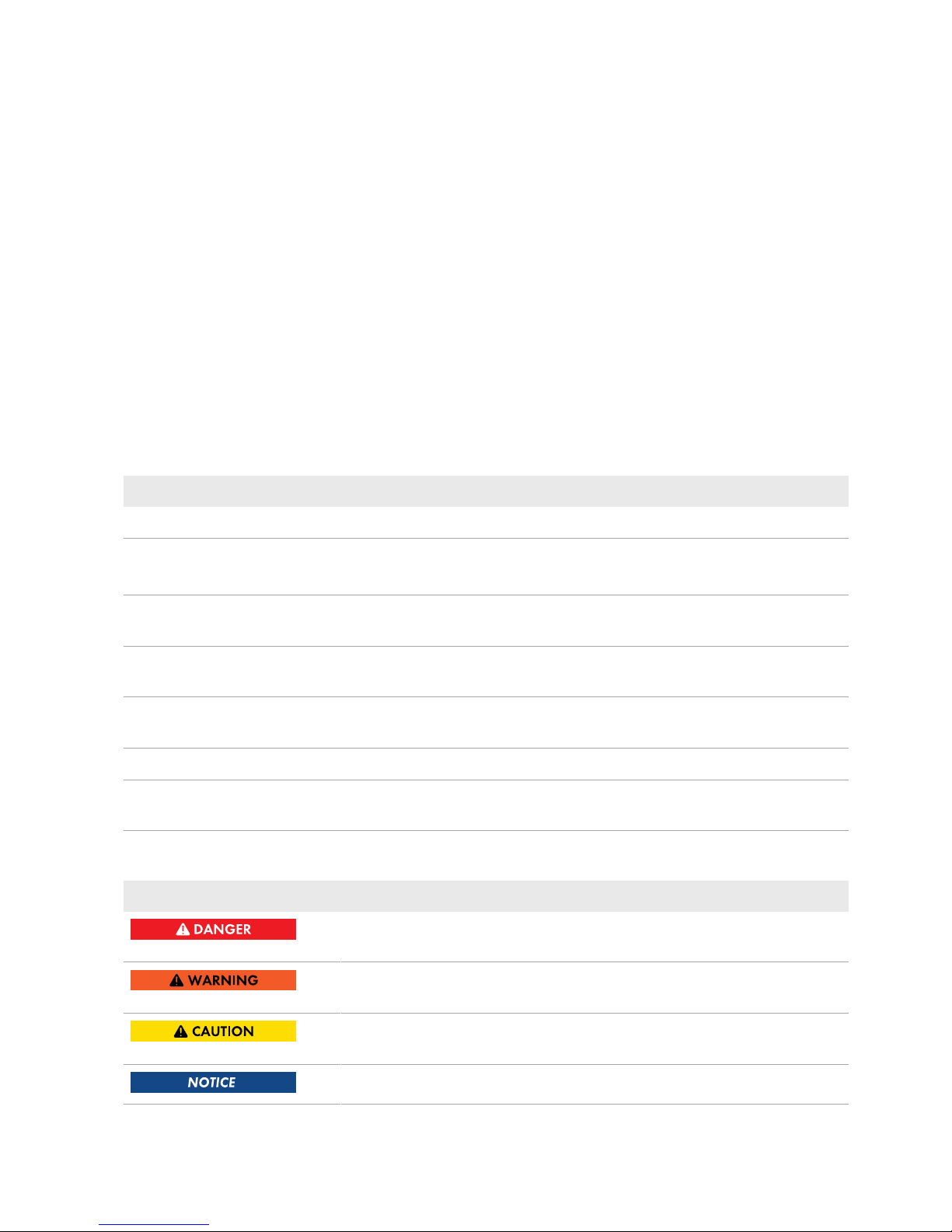
4.4 System Structure
The SunnyHomeManager has an integrated measuring device. Depending on the application, the
SunnyHomeManager is integrated and configured differently in the system (see Section8.2, page33):
PV system with SMA inverters and measurement at the grid-connection point (recommended)
SUNNY PORTAL
INTERNET
SUNNY HOME
MANAGER 2.0
Ethernet
SUNNY BOY 1.5/2.5 SUNNY BOY TL
UTILITY GRID
PV MODULES
ROUTER
UTILITY METER
FOR BILLING
PURPOSES
INTELLIGENT
APPLIANCE
via ETHERNET
RADIO-CONTROLLED
SOCKETS
via WLAN
INTELLIGENT
APPLIANCE
via WLAN
APPLIANCE
WLAN
AC
DC
PV MODULES
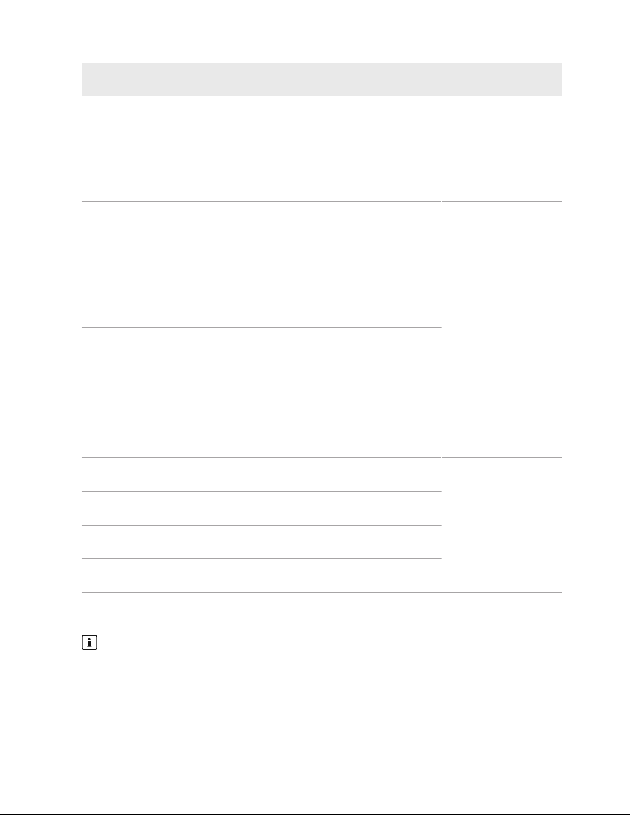
PV system with inverters of other manufacturers and measurement at the grid-connection point
and the PV generation using a SunnyHomeManager and an SMAEnergyMeter
SUNNY PORTAL
INTERNET
SMA ENERGY METER
Ethernet
SUNNY BOY 1.5/2.5
SUNNY HOME
MANAGER 2.0
UTILITY GRID
PV MODULES
ROUTER
UTILITY METER
FOR BILLING
PURPOSES
INTELLIGENT
APPLIANCE
via ETHERNET
RADIO-CONTROLLED
SOCKETS
via WLAN
INTELLIGENT
APPLIANCE
via WLAN
APPLIANCE
WLAN
AC
DC
PV MODULES
PV INVERTER
4Product Description
SMA Solar Technology AG
Operating ManualHM-20-BE-en-1024

SunnyHomeManager without using the integrated measuring device
SUNNY PORTAL
INTERNET
SMA ENERGY METER
Ethernet
SUNNY BOY 1.5/2.5
SUNNY HOME
MANAGER 2.0
L1 / N
UTILITY GRID
PV MODULES
ROUTER
UTILITY METER
FOR BILLING
PURPOSES
INTELLIGENT
APPLIANCE
via ETHERNET
RADIO-CONTROLLED
SOCKETS
via WLAN
INTELLIGENT
APPLIANCE
via WLAN
APPLIANCE
WLAN
AC
DC
4 Product Description
SMA Solar Technology AG
Operating Manual 25HM-20-BE-en-10

5 Mounting
5.1 Requirements for Mounting the SunnyHomeManager
☐ The mounting location must be indoors.
☐ The SunnyHomeManager must be installed in a switch cabinet.
☐ The mounting location must be protected against dust, moisture and corrosive substances.
☐ The cable route from the mounting location to the router must not exceed a maximum length of 100m.
☐ A minimum distance of 1m must be maintained from devices using the 2.4GHz radio spectrum (e.g. WLAN
devices, microwave ovens). This will prevent reduced connection quality and data transmission speed.
☐ The ambient conditions at the mounting location must be suitable for the operation of the SunnyHomeManager
(see Section21, page124).
5.2 Mounting the SunnyHomeManager on the Top-Hat Rail
Requirement:
☐ The top-hat rail must be securely mounted in the switch cabinet.
Procedure:
1. Press the SunnyHomeManager with the upper retainers into
the upper edge of the top-hat rail.
2. Hook the lower retainers into the lower edge of the top-hat rail.
5Mounting
SMA Solar Technology AG
Operating ManualHM-20-BE-en-1026

6 Preparing for Speedwire Communication
If the SunnyHomeManager is to communicate with other SMA devices via Speedwire, the SunnyHomeManager
and the Speedwire devices must be in the same local network. Perform the following preparatory steps.
Inverters with Webconnect function
If an inverter is already registered in SunnyPortal with the Webconnect function, the inverter cannot be added to
the SunnyHomeManager system in SunnyPortal.
• In order to be able to add the inverter to the SunnyHomeManager system in SunnyPortal, delete the
inverter with Webconnect function from the Webconnect system in SunnyPortal or deactivate data reception
for the inverter in the Webconnect system in SunnyPortal.
Requirements:
☐ DHCP must be active on the router (see router documentation). If your router does not support DHCP, you can
configure the static network settings on the Speedwire device using SMAConnectionAssist.
☐ All UDP ports > 1024 on the router or modem must be open for outgoing connections. If there is a firewall
installed on the router or modem, you might have to adjust the firewall rules.
☐ It must be possible for the outgoing router or modem connections to reach all Internet destinations (target IP,
target port). If there is a firewall installed on the router or modem, you might have to adjust the firewall rules.
☐ On the router or modem with NAT (Network Address Translation), no port forwarding must be entered. Potential
communication problems can thus be prevented.
☐ There must be no packet filtering or manipulation for SIP packets on the router or modem.
☐ The routers and network switches with router function must forward the Multicast telegrams (telegrams with
destination address 239.0.0.0 to 239.255.255.255) required for the Speedwire connection to all nodes of the
Speedwire network.
☐ All network components used must support the IGMP protocol, minimum version3 (IGMPv3) (see network
component documentation).
Procedure:
1.
Deactivating the BLUETOOTH communication of the inverters
If an inverter communicates simultaneously via Speedwire/WLAN and BLUETOOTH, data recording errors
will result. The SunnyHomeManager does not support communication with BLUETOOTH.
• For inverters with BLUETOOTHinterface, set NetID0 (see inverter- or BLUETOOTHPiggy-Back
documentation). This deactivates communication via BLUETOOTH.
2. Connect the Speedwire devices to the router / network switch (see Speedwire device documentation). Make sure
that the distance to the mounting location of the SunnyHomeManager is not too great, as the
SunnyHomeManager must later be connected to the same router/network switch.
6 Preparing for Speedwire Communication
SMA Solar Technology AG
Operating Manual 27HM-20-BE-en-10

7 Connection
7.1 Connecting the SunnyHomeManager to the Router
1. Connect the network cable to the network terminal of the
SunnyHomeManager. The network cable must be suitable for
connection to the SunnyHomeManager (see Section4.1.4
"System Requirements", page21).
R
eset
SUNNY HOME MANA
GER 2.0
2. Connect the other end of the network cable to the router.
7.2 Connecting the SunnyHomeManager to the SMAEnergyMeter
The SMAEnergyMeter and the SunnyHomeManager must be connected to the same router.
Additionally required material (not included in the scope of delivery):
☐ 1 network cable (see Section4.1.4 "System Requirements", page21)
Procedure:
1. Connect the SMAEnergyMeter to the router (see SMAEnergyMeter installation manual).
2. Connect the SunnyHomeManager to the router (see Section7.1, page28).
7.3 Replacing the SMAEnergyMeter
1. Write down the serial number of the new SMAEnergyMeter. The serial number is to be found on the type label
of the SMAEnergyMeter.
2. Configure the new SMAEnergyMeter in SunnyPortal (see Section12.6 "Configuring the Energy Meter",
page67).
7.4 Connecting a Smart Appliance
Some modern home appliances have an Ethernet connection with which the data of the device can be called up via
the local network. If there is an Internet connection via the network router, the manufacturers of household devices can
use this data for maintenance purposes, for example. Visualization and control of the household devices via mobile
devices (e.g. via app in the Smartphone) is also possible with this. If the manufacturer of the networked household
devices, in cooperation with SMA Solar Technology AG, has implemented a special data exchange protocol for
energy management in the device control, the SunnyHomeManager can control these loads directly via the local
network. For information on the supported products (see Section2.3, page11). The smart appliances send information
on the load type, the planned energy requirement, and the preferred operating time period to the
SunnyHomeManager. The SunnyHomeManager factors this information into its load control, and also taking the
configured optimization targets in the context of load control into account, sends appropriate start and stop signals to
the loads.
Requirements:
☐ The device must support the data exchange protocol defined by SMA Solar Technology AG.
☐ The SunnyHomeManager must be located in the same local network as the device.
7Connection
SMA Solar Technology AG
Operating ManualHM-20-BE-en-1028

Additionally required material (not included in the scope of delivery):
☐ 1 network cable (see Section4.1.4, page21)
Procedure:
1. Connect the network cable to the device (see device documentation).
2. Connect the other end of the network cable to the router or network switch.
☑ The device is automatically recognized by the SunnyHomeManager. Once you have added the controllable
device to the SunnyHomeManager system via the configuration wizard in SunnyPortal, the
SunnyHomeManager will control the device automatically via the defined data exchange protocol.
Pairing
In the case of EEBus compatible home appliances, a pairing must be performed. The new device will appear in
SunnyPortal only once the pairing has been completed successfully (see technical information: "SMA SMART
HOME - Home appliance energy management using EEBus").
7.5 Voltage supply terminal
7.5.1 Requirements for connecting the voltage supply
Danger to life due to electric shock if external disconnect switch is missing
Lethal voltages are present in the live components.
• Install an external disconnect switch between the product and the grid-connection point. The external
disconnector must be close to the product and easily accessible.
Danger to life due to electric shock
Lethal voltages are present in the live components.
• Disconnect the connection point from voltage sources and make sure it cannot be reconnected.
• Before performing any work on the product, disconnect the grid side from all voltage sources using the installed
disconnect switch.
• Ensure that the conductors to be connected are de-energized.
• Only use the product in a dry environment and keep it away from moisture.
• Install the product in the switch cabinet only and ensure that the connection areas for the line conductors and
the neutral conductor are behind a cover or have contact protection.
• Disconnect the product from voltage sources before cleaning and clean it with a dry cloth only.
• Observe the prescribed minimum clearance between the network cable and live installation components, or use
suitable insulation.
Requirements:
☐ The setpoints of the electric utility company must be observed.
☐ At least the line conductor L1 and the neutral conductor must be connected. As a result, the
SunnyHomeManager is supplied with voltage.
☐ When using fine stranded conductors, bootlace ferrules must be used.
Cable requirements:
☐ Conductor cross-section without current transformer:10 to 16 mm²
7 Connection
SMA Solar Technology AG
Operating Manual 29HM-20-BE-en-10

☐ Conductor cross-section with current transformer: see recommendations of the current transformer manufacturer
7.5.2 Connecting the Voltage Supply for Applications up to 63 A
L1L2L3
N
SUNNY HOME MANAGER 2.0
L1 L2 L3
Reset
L1 L2 L3
NL1 L2 L3
L1 L2 L3
L1 L2 L3
N
Router/
Switch
Sunny
Portal
Internet
WLAN
Ethernet
OUT
IN
Household
Disconnect switch
Energy meter of
the electric
utility company
Main breaker
(three-phase)
Utility grid
Inverters
Sunny Home Manager 2.0
as purchased electricity
and feed-in meter
L1, L2, L3: Line conductor
N: Neutral conductor
OUT: Meter output, load side
IN: Meter input, grid side
Figure 4: The following figure shows a connection example in TN and TT utility grids in the case of installation at the grid-connection point when
using the integrated measuring unit.
Procedure:
1. Disconnect the connection point from voltage sources and make sure it cannot be reconnected.
2. Connect the line conductors to the SunnyHomeManager:
• When using the integrated measuring device and a three-phase utility grid, connect the line conductors L1,
L2, L3 and N to the screw terminals at the input of the SunnyHomeManager. Open each screw terminal
using a cross-head screwdriver, insert the conductor into the contact terminal and tighten the screw using a
cross-head screwdriver (torque: 2.0Nm).
• When using the integrated measuring device and the single-phase utility grid, connect the line conductors L1
and N to the screw terminals at the input of the SunnyHomeManager. Open each screw terminal using a
cross-head screwdriver, insert the conductor into the contact terminal and tighten the screw using a crosshead screwdriver (torque: 2.0Nm).
• When not using the integrated measuring device, connect the line conductor L1 and the neutral conductor to
the screw terminals at the input of the SunnyHomeManager. Open each screw terminal using a cross-head
screwdriver, insert the conductor into the contact terminal and tighten the screw using a cross-head
screwdriver (torque: 2.0Nm).
7Connection
SMA Solar Technology AG
Operating ManualHM-20-BE-en-1030
 Loading...