

Siemens TLE4205G, TLE4205 Datasheet
1-A DC Motor Driver
TLE 4205
Overview Bipolar IC
Features
● Max. driver current 1 A
● Integrated free-wheeling diodes
● Short-circuit proof to ground
● Inhibit
● ESD protected inputs
● Temperature range – 40 °C ≤ T
≤ 150 °C
j
P-DIP-18-3
P-DSO-20-6
Type Ordering Code Package
TLE 4205 Q67000-A9025 P-DIP-18-3
TLE 4205 G Q67006-A9114 P-DSO-20-6
Description
TLE 4205 is an integrated power full-bridge DC-motor driver for a wide temperature
range, as required in automotive applications for example. The circuit contains two
power comparators that can be combined to a full-bridge circuit. For inductive loads
V
there are integrated free -wheeling diodes to +
and ground. The outputs are short-
S
circuit proof up to 18 V supply voltage to ground and turn off when overtemperature
occurs. This IC is especially suitable for headlight-beam adjustment in automobiles.
Semiconductor Group 1 1998-02-01
TLE 4205
Q1
V
Q2
GND
ΙΙ-+
+Ι1
Ι1-
TLE 4205
1
2
S
3
4
5
2
6
2
7
8
9
18
17
16
15
14
13
12
11
10INH
AEP00636
GND
must be connected
to Pin 4
Q2
N.C.
N.C.
GND
GND
GND
GND
2
-
Ι
2+
Ι
Ι
+
1
TLE 4205 G
12
11
V
S
Q1
N.C.
GND
GND
GND
GND
N.C.
NH
Ι
Ι
-1
120
219
318
417
516
615
714
813
9
10
AEP01318
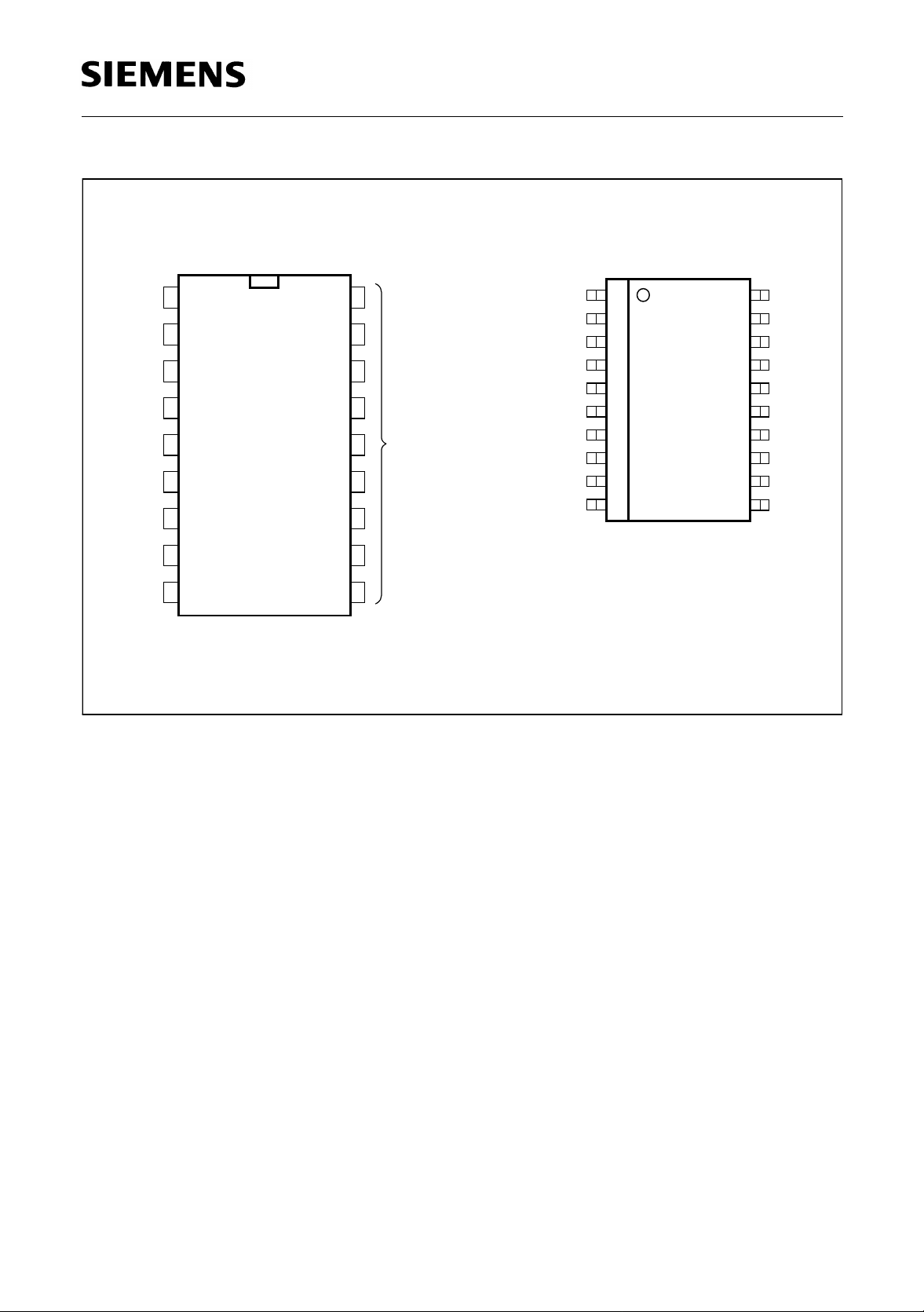
Figure 1 Pin Configuration (top view)
Semiconductor Group 2 1998-02-01
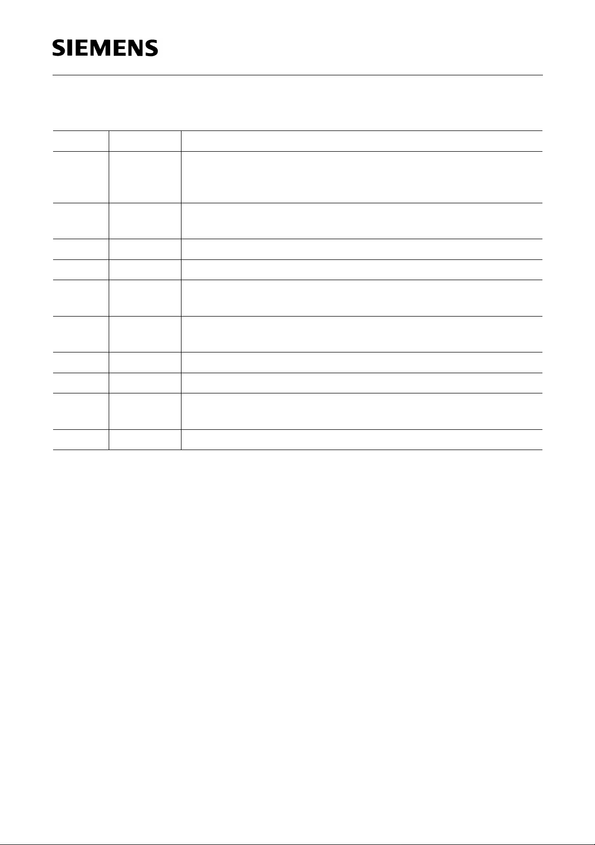
Pin Definitions and Functions
Pin No. Symbol Function
1Q1Output Q1 of channel 1; push-pull B output with DC
short-circuit protection to ground. Integrated free-wheeling
diodes to ground and the supply voltage.
TLE 4205
2
V
S
Supply voltage VS; must be blocked to ground with a ceramic
capacitor of at least 100 nF directly on the pins of the IC.
3Q2Output Q2 of channel 2; see pin 1.
4 GND Ground
5 – I2 Inverting input channel 2; to be wired according to general
rules.
6 + I2 Non-inverting input channel 2; to be wired according to
general rules.
7 + I1 Non-inverting input channel 1; see pin 6.
8 – I1 Inverting input channel 1; see pin 5.
9INHInhibit; the IC is passive when this pin is open or connected to
ground.
10-18 GND Ground; must be connected to pin 4.
Semiconductor Group 3 1998-02-01
TLE 4205
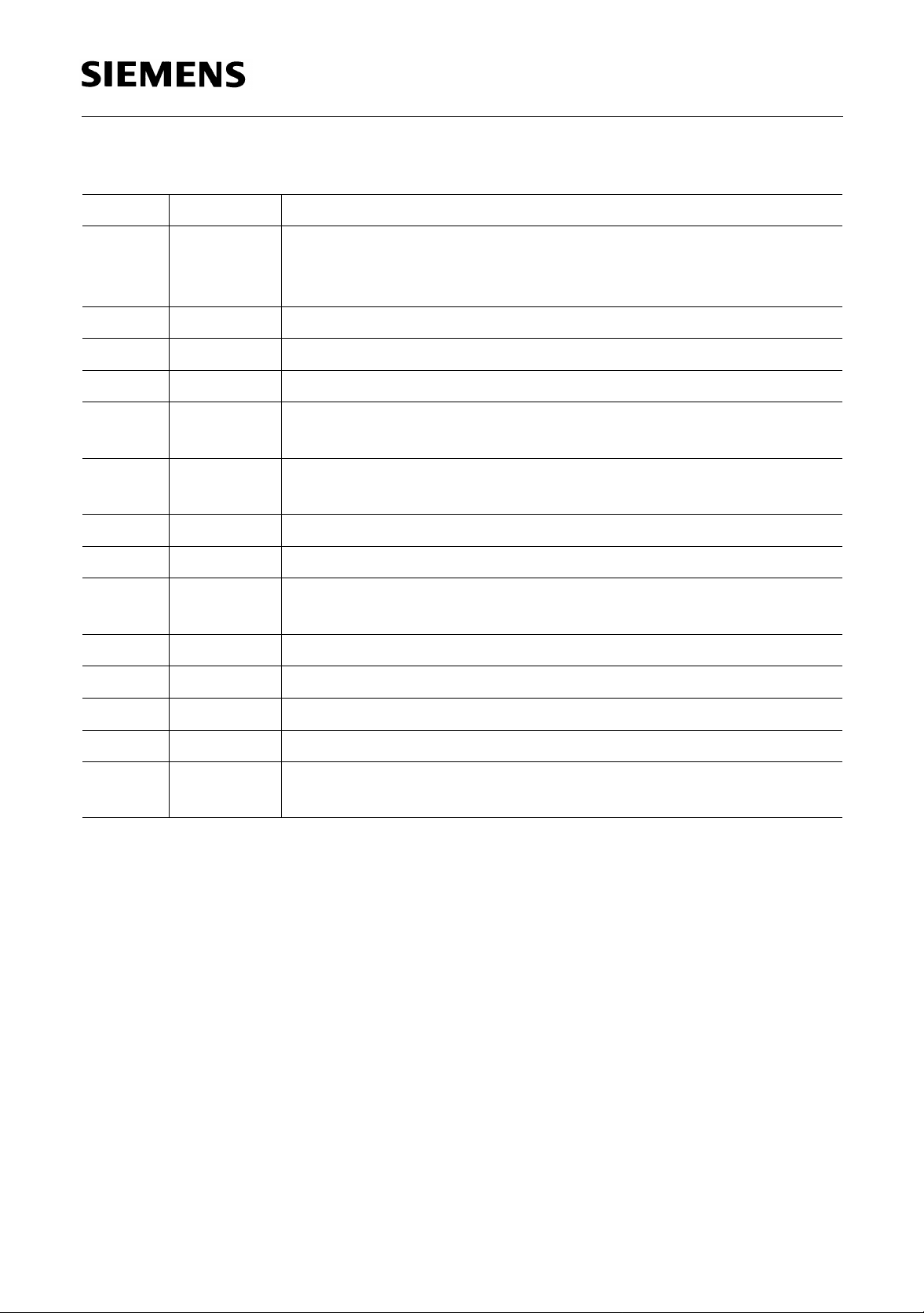
Pin Definitions and Functions (TLE 4205 G)
Pin No. Symbol Function
1Q2Output 2 of channel 2; push-pull B out put with DC shor t-circui t
protection to ground. Integrated free-wheeling diodes to ground
and the supply voltage.
2 N.C. Not connected
3 N.C. Not connected
4-7 GND Ground
8 – I2 Inverting input channel 2; to be wired according to general
rules.
9 + I2 Non-inverting input channel 2; to be wired according to
general rules.
10 + I1 Non-inverting input channel 1; see pin 9.
11 – I1 Inverting input channel 1; see pin 8.
12 INH Inhibit; the IC is passive when this pin is open or connected to
ground.
13 N.C. Not connected
14-17 GND Ground
18 N.C. Not connected
19 Q1 Output Q1 of channel 1, see pin 1.
20
V
S
Supply voltage VS; must be blocked with a ceramic capacitor
of at least 100 nF directly on the pins of the IC.
Semiconductor Group 4 1998-02-01
 Loading...