

Siemens TH 188, TH 188D, TH 188HC, TH 188R Installation Instructions Manual
TH 188 Unit Mounted Thermostats
Product Description
The TH 188 Unit Mounted Thermostat is a remote
bulb, gradual acting pneumatic instrument that
maintains a preselected room temperature by
positioning pneumatic devices that control heating or
cooling medium. This thermostat has a liquid filled
thermal system.
Product Numbers
Installation Instructions
Document No. 129-129
Rev. 3, August, 2000
TH 188R Reverse Acting (RA)
20 scim (5.5 ml/s) restrictor
TH 188HC Heating (direct)/Cooling
(reverse) 40 scim (11 ml/s) restricto r
TH 188D Direct Acting (DA)
40 scim (11 ml/s) restrictor
Replacement for Honeywell models
LP916BXXXX
Heating (direct)/Cooling (reverse)
40 scim (11 ml/s) restrictor
Replacement for Johnson Controls
T-3300-2
Heating (direct)/Cooling (reverse)
40 scim (11 ml/s) restrictor
Required Tools
•
Medium flat-blade screwdriver
•
Small drill
Expected Installation Time
90 minutes (1 hour and 30 minutes)
188-0024
188-0030
188-0031
188-0033
188-0034
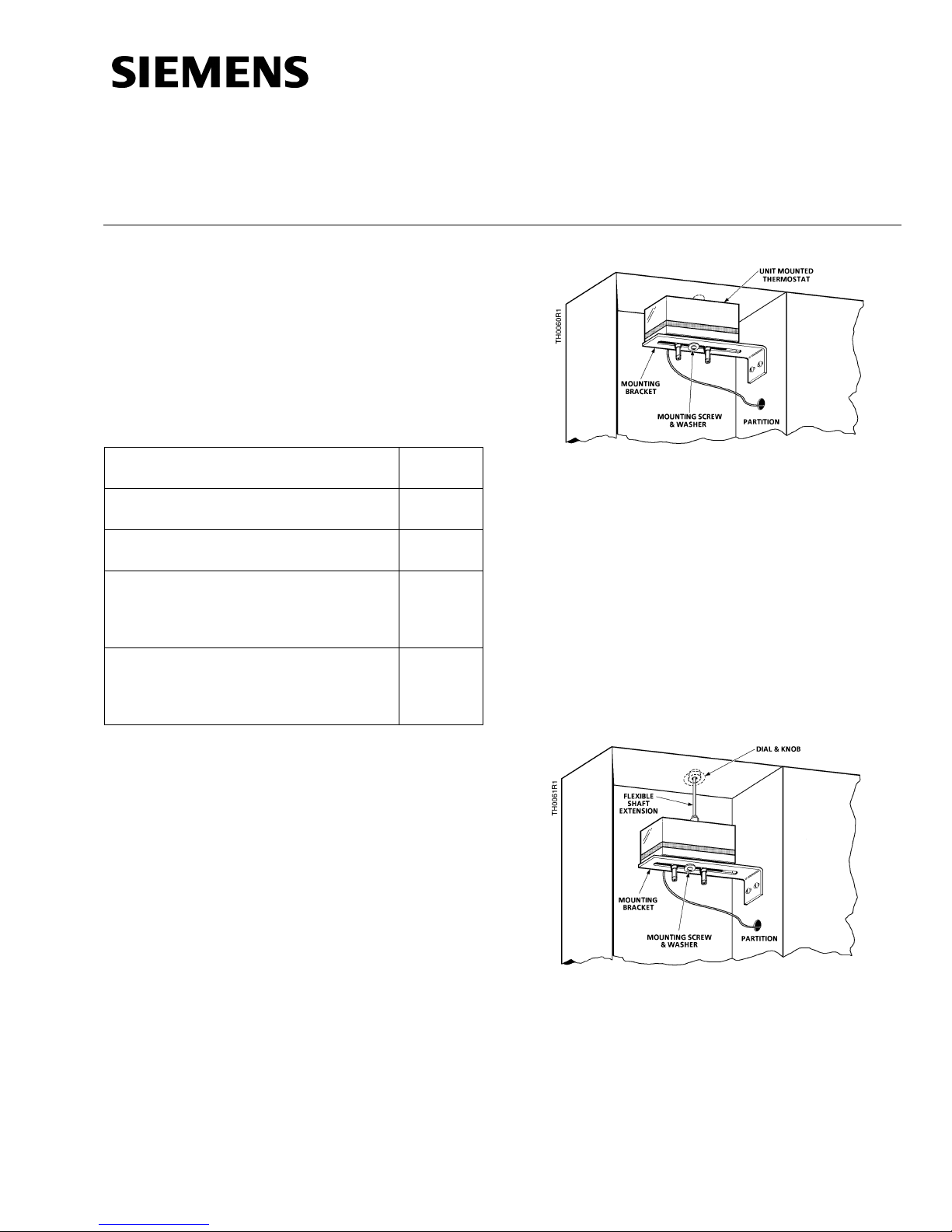
Figure 1. Thermostat and Mounting Bracket.
NOTE:
If there is not enough room to mount the
thermostat in a convenient location, or if
the set point dial must be in the same
compartment as the fan switch, order an
extension shaft kit (Part Number 188-101).
Figure 2
See
Using the extension shaft, mount the
thermostat in any convenient location
within eight inches of the control
compartment.
.
Installation
A mounting bracket is included for mounting the
thermostat in various units.
1. Fasten the mounting bracket to the partition
with two sheet metal screws included with the
thermostat.
installation.
Figure 1
shows a typical
Figure 2. Use of Shaft Extension.
2. Mount the remote sensing bulb in the air stream
of the return air (near the inlet of the fan).
Avoid metal to metal contact between the bulb
and the unit to prevent damage to the soft
copper sensing bulb from unit vibration.
Page 1 of 3
Document No. 129-129
Installation Instructions
Rev. 3, August, 2000
Installation, Continued
3. Fasten the capillary and/or bulb in the return air
stream using the adhesive backed cable clip
included in the kit.
4. Make air connections to the "S" (supply) Port
and "R" (return) Port. Thermostats have a
barbed fitting for 1/4-inch (6.4 mm) O.D. poly
tubing.
Calibration
The thermostats are factory calibrated at 72°F
(22°C) and 7-1/2 psi (52 kPa) control pressure.
General
1. Determine the temperature at the remote bulb.
2. Set knob pointer to the temperature found. Dial
increments are approximately 5 degrees on the
major divisions with 1 degree subdivisions,
beginning at 60°F clockwise to 85°F.
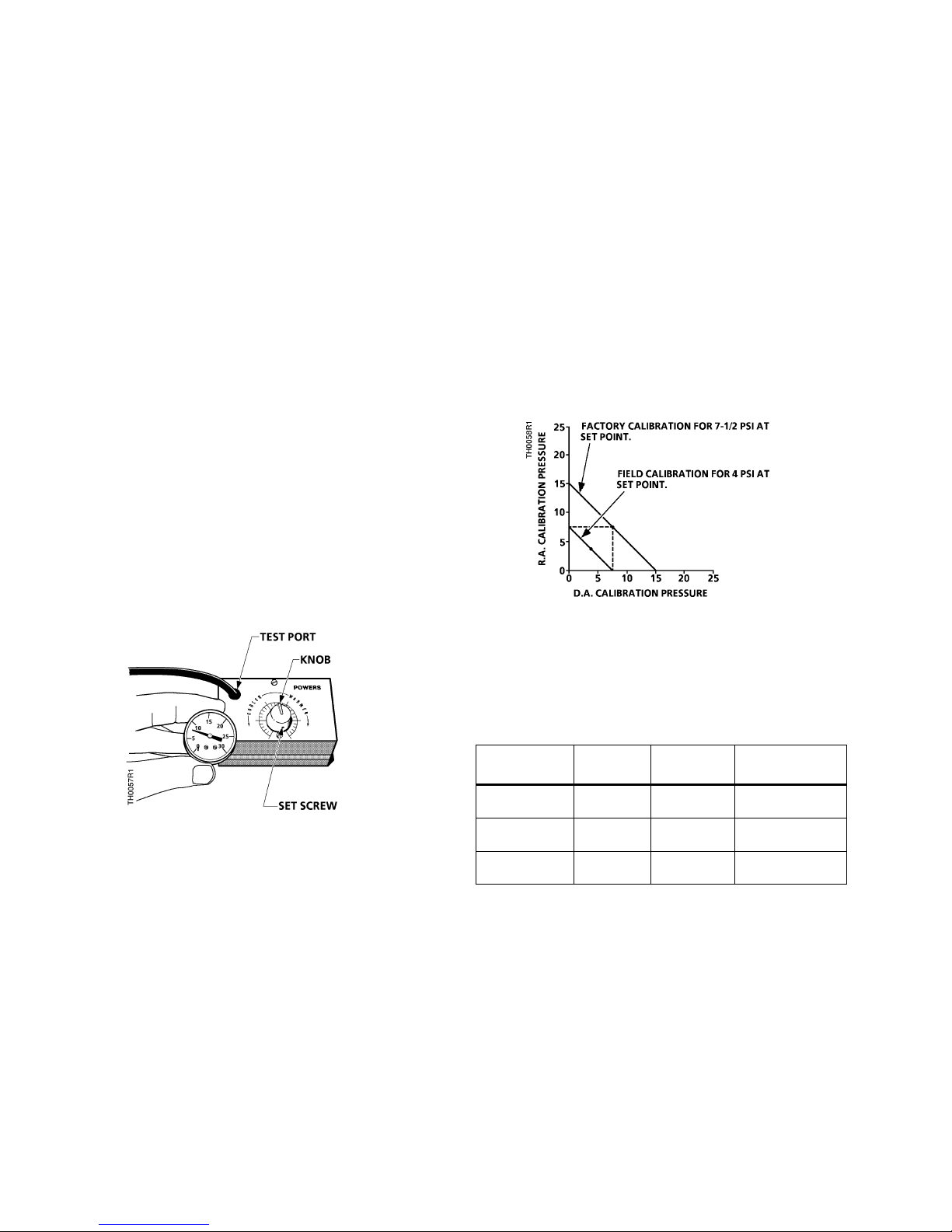
3. Loosen (do not remove) return line test port
screw. Slip rubber line over test port and
connect to a test gauge (
Figure 3
).
Dual action
On the HC thermostat, calibration should be at
7-1/2 psi (52 kPa) for both DA and RA. The unit has
one thermal system with a reversing relay to give the
action desired. If calibrated at 7-1/2 psi (52 kPa) for
winter, the summer calibration will be 7-1/2 psi
(52 kPa). If 9 psi (62 kPa) is used for winter, 6 psi
(41 kPa) will be summer's calibrated pressure.
Figure 4
calibration points. If the same pressure is desired for
both seasons, the RA section of the thermostat
needs to be recalibrated (follow the RA calibration
procedures).
shows the relationship of the DA and RA
Figure 4. Dual Action Calibration Points.
Figure 3. Test Port and Gauge Used for Calibration.
4. With the knob pointer set at the temperature of
the remote bulb, the output (return line) pressure
should be 7 to 8 psi (48 & 55 kPa) for all models.
If the output pressure is not 7 to 8 psi (48 to
55 kPa), remove knob after loosening its set
screw. Then, rotate the set point adjustment
post until output pressure is 7 to 8 psi.
5. Replace knob and set pointer to temperature of
the bulb, lock, and then turn to desired setting.
The thermostat is now in calibration.
Single action
The direct acting or reverse acting thermostat may
be calibrated at any pressure. It is suggested that
7-1/2 psi (52 kPa) be used.
Reverse acting stage
Table 1
See
pressure.
Table 1. Air Supply Pressure and Changeover.
Type and
Model No.
Powers HC
(TH188HC)
Honeywell
HC (LP916B)
Johnson HC
(T-3300-2)
The reverse acting stage is factory adjusted and
does not require field adjustment. If the adjustment
is disturbed, re-adjust as follows:
1. With the main air supply set for 25 psi
(172 kPa), connect a Pressure Reducing Valve
(PRV) with gauge to the supply side of
thermostat and set at 25 psi (172 kPa).
2. Remove knob and cover from thermostat, as
shown in
3. Open bleed screw on test port and connect
gauge (
for air pressure and changeover
Heating
(Da)
25 psi
(172 kPa)
18 psi
(124 kPa)
20 psi
(138 kPa)
Figure 3
Figure 5
).
.
Cooling
(Ra)
18 psi
(124 kPa)
13 psi
(124 kPa)
15 psi
(103 kPa)
Changeover
(145 kPa)
(103 kPa)
(117 kPa)
21 psi
15 psi
17psi
Page 2 of 3
Siemens Building Technologies, Inc.
 Loading...