

Page 1
m
o
bil e
MC55
Siemens Cellular Engine
Version: 01.05
DocId: MC55_ATC_V01.05
Page 2

MC55 AT Command Set
s
m
obil
e
Document Name:
Version:
Date:
DocId:
Status
General Notes
Product is deemed accepted by recipient and is provided without interface to recipient’s products. The documentation and/or product are provided for testing, evaluation, integration and information purposes. The documentation and/or product are provided on an “as is” basis only and may contain deficiencies or inadequacies. The
documentation and/or product are provided without warranty of any kind, express or implied. To the maximum
extent permitted by applicable law, Siemens further disclaims all warranties, including without limitation any implied warranties of merchantability, completeness, fitness for a particular purpose and non-infringement of thirdparty rights. The entire risk arising out of the use or performance of the product and documentation remains with
recipient. This product is not intended for use in life support appliances, devices or systems where a malfunction
of the product can reasonably be expected to result in personal injury. Applications incorporating the described
product must be designed to be in accordance with the technical specifications provided in these guidelines. Failure to comply with any of the required procedures can result in malfunctions or serious discrepancies in results.
Furthermore, all safety instructions regarding the use of mobile technical systems, including GSM products,
which also apply to cellular phones must be followed. Siemens or its suppliers shall, regardless of any legal theory upon which the claim is based, not be liable for any consequential, incidental, direct, indirect, punitive or other
damages whatsoever (including, without limitation, damages for loss of business profits, business interruption,
loss of business information or data, or other pecuniary loss) arising out the use of or inability to use the documentation and/or product, even if Siemens has been advised of the possibility of such damages. The foregoing
limitations of liability shall not apply in case of mandatory liability, e.g. under the German Product Liability Act, in
case of intent, gross negligence, injury of life, body or health, or breach of a condition which goes to the root of
the contract. However, claims for damages arising from a breach of a condition, which goes to the root of the
contract, shall be limited to the foreseeable damage, which is intrinsic to the contract, unless caused by intent or
gross negligence or based on liability for injury of life, body or health. The above provision does not imply a
change on the burden of proof to the detriment of the recipient. Subject to change without notice at any time. The
interpretation of this general note shall be governed and construed according to German law without reference
to any other substantive law.
MC55 AT Command Set
01.05
February 10, 2004
MC55_ATC_V01.05
Confidential / Released
Copyright
Transmittal, reproduction, dissemination and/or editing of this document as well as utilization of its contents and
communication thereof to others without express authorization are prohibited. Offenders will be held liable for
payment of damages. All rights created by patent grant or registration of a utility model or design patent are reserved.
Copyright © Siemens AG February 10, 2004
MC55_ATC_V01.05 Page 2 of 469 2/10/04
Confidential / Released
Page 3

MC55 AT Command Set
Contents
s
m
obil
e
Contents
1. Introduction............................................................................................................................................ 13
1.1 Scope of the document ................................................................................................................. 13
1.2 Related documents ....................................................................................................................... 14
1.3 Document conventions.................................................................................................................. 15
1.3.1 Quick reference table ....................................................................................................... 15
1.3.2 Superscript notation for parameters and values............................................................... 16
1.4 AT command syntax...................................................................................................................... 17
1.4.1 Using parameters............................................................................................................. 17
1.4.2 Combining AT commands on the same command line.................................................... 18
1.5 Supported character sets .............................................................................................................. 19
1.5.1 GSM alphabet tables and UCS2 character values ........................................................... 21
1.5.2 UCS2 and GSM data coding and conversion for SMS text mode.................................... 23
1.5.2.1 Implementing output of SIM data to the TE (direction ME to TE)..................................... 23
1.5.2.2 Implementing input of Terminal data to SIM (direction TE to ME) .................................... 24
1.6 Flow Control .................................................................................................................................. 26
1.6.1 Software flow control (XON/OFF flow control) ................................................................. 26
1.6.2 Hardware flow control (RTS/CTS flow control)................................................................. 26
1.7 Unsolicited Result Code Presentation........................................................................................... 27
1.7.1 Communication between Customer Application and MC55 ............................................. 27
1.8 Common PCN Handset Specification (CPHS) .............................................................................. 28
1.9 Errors and Messages .................................................................................................................... 29
2. Configuration Commands..................................................................................................................... 30
2.1 AT&F Set all current parameters to manufacturer defaults ......................................................... 30
2.2 AT&V Display current configuration ............................................................................................31
2.2.1 AT&V responses .............................................................................................................. 31
2.3 AT&W Stores current configuration to user defined profile ......................................................... 33
2.4 ATQ Set result code presentation mode ..................................................................................... 34
2.5 ATV Set result code format mode ...............................................................................................35
2.5.1 Verbose and numeric result codes................................................................................... 35
2.6 ATX Set CONNECT result code format and call monitoring ....................................................... 37
2.7 ATZ Set all current parameters to user defined profile................................................................ 38
2.8 AT+CFUN Set phone functionality .............................................................................................. 39
2.8.1 Wake up the ME from SLEEP mode ................................................................................ 43
2.9 AT^SMSO Switch off mobile station............................................................................................ 44
2.10 AT+GCAP Request complete TA capabilities list........................................................................ 45
2.11 AT+CMEE Report mobile equipment error ................................................................................. 46
2.11.1 Summary of CME ERRORS related to GSM 07.07 ......................................................... 47
2.11.2 Summary of GPRS-related CME ERRORS ..................................................................... 48
MC55_ATC_V01.05 Page 3 of 469 2/10/04
Confidential / Released
Page 4

MC55 AT Command Set
Contents
2.11.3 Summary of CMS ERRORS related to GSM 07.05 ......................................................... 49
2.12 AT+CSCS Select TE character set ............................................................................................. 52
2.13 AT^SCFG Extended Configuration Setting ................................................................................. 54
2.14 AT^SM20 Set M20 compatibility mode ....................................................................................... 61
3. Status Control Commands ................................................................................................................... 63
3.1 AT+CMER Mobile Equipment Event Reporting .......................................................................... 63
3.2 AT+CIND Indicator control .......................................................................................................... 66
3.3 AT^SIND Extended Indicator Control .......................................................................................... 70
3.4 AT+CEER Extended error report ................................................................................................ 73
3.4.1 Cause Location ID for the extended error report.............................................................. 75
3.4.2 GSM release cause for L3 Radio Resource (RR) ............................................................ 76
3.4.3 SIEMENS release cause for L3 Radio Resource (RR) .................................................... 77
3.4.4 GSM release cause for Mobility Management (MM) ........................................................ 77
3.4.5 SIEMENS release cause for L3 Mobility Management (MM) ........................................... 78
3.4.6 GSM release cause for L3 Call Control (CC) ................................................................... 78
3.4.7 SIEMENS release cause for L3 Call Control (CC) ........................................................... 80
3.4.8 SIEMENS release cause for L3 Advice of Charge (AOC)................................................ 81
3.4.9 GSM Release cause for Supplementary Service Call ...................................................... 81
3.4.10 SIEMENS release cause for Call-related Supplementary Services (CRSS) .................... 82
3.4.11 SIEMENS release cause for Session Management (SM) ................................................ 83
3.4.12 GSM cause for L3 Protocol module or other local cause ................................................ 84
3.4.13 SIEMENS release cause for GPRS API........................................................................... 84
3.4.14 SIEMENS release cause for Embedded Netcore............................................................. 84
3.5 ATS18 Extended call release report............................................................................................85
s
m
obil
e
3.6 AT+CPAS Mobile equipment activity status................................................................................ 87
3.7 AT+WS46 Select wireless network ............................................................................................. 88
4. Serial Interface Control Commands..................................................................................................... 89
4.1 AT\Q Flowcontrol......................................................................................................................... 89
4.2 AT&C Set circuit Data Carrier Detect (DCD) function mode ....................................................... 90
4.3 AT&D Set circuit Data Terminal Ready (DTR) function mode..................................................... 91
4.4 AT&S Set circuit Data Set Ready (DSR) function mode ............................................................. 92
4.5 ATE Enable command echo........................................................................................................ 93
4.6 AT+ILRR Set TE-TA local rate reporting ..................................................................................... 94
4.7 AT+IPR Set fixed local rate ......................................................................................................... 96
4.7.1 Autobauding ..................................................................................................................... 98
4.8 AT+CMUX Enter multiplex mode ................................................................................................ 99
4.8.1 Restrictions on Multiplex mode ...................................................................................... 100
4.8.2 Second serial interface ASC1 ........................................................................................ 102
5. Security Commands ............................................................................................................................ 103
5.1 AT+CPIN Enter PIN .................................................................................................................. 103
5.1.1 What to do if PIN or password authentication fails? ....................................................... 105
5.2 AT+CPIN2 Enter PIN2 .............................................................................................................. 107
MC55_ATC_V01.05 Page 4 of 469 2/10/04
Confidential / Released
Page 5

MC55 AT Command Set
Contents
5.3 AT^SPIC Display PIN counter ...................................................................................................110
5.4 AT+CLCK Facility lock .............................................................................................................. 115
5.5 AT^SLCK Facility lock ............................................................................................................... 121
5.6 AT+CPWD Change Password .................................................................................................. 122
5.7 AT^SPWD Change Password ................................................................................................... 126
6. Identification Commands.................................................................................................................... 127
6.1 ATI Display product identification information ........................................................................... 127
6.2 AT+CGMI Request manufacturer identification......................................................................... 128
6.3 AT+GMI Request manufacturer identification ........................................................................... 129
6.4 AT+CGMM Request model identification .................................................................................. 130
6.5 AT+GMM Request TA model identification ............................................................................... 131
6.6 AT+CGMR Request revision identification of software status................................................... 132
6.7 AT+GMR Request TA revision identification of software status................................................ 133
6.8 AT+CGSN Request product serial number identification (IMEI) identical to GSN .................... 134
s
m
obil
e
6.9 AT+GSN Request TA serial number identification (IMEI) ......................................................... 135
6.10 AT+CIMI Request international mobile subscriber identity ....................................................... 136
7. Call related Commands....................................................................................................................... 137
7.1 Call Status Information ................................................................................................................ 137
7.2 ATA Answer a call ..................................................................................................................... 139
7.3 ATD Mobile originated call to dial a number.............................................................................. 140
7.4 ATD><mem><n> Originate call to phone number in memory................................................... 143
7.5 ATD><n> Originate call to phone number selected from active memory.................................. 145
7.6 ATD><str> Originate call to phone number in memory with corresponding field ...................... 147
7.7 ATDI Mobile originated call to dialable ISDN number <n> ........................................................ 149
7.8 ATDL Redial last telephone number used................................................................................. 150
7.9 ATH Disconnect existing connection......................................................................................... 151
7.10 AT+CHUP Hang up call ............................................................................................................ 152
7.11 ATS0 Set number of rings before automatically answering the call .......................................... 153
7.12 ATS6 Set pause before blind dialing ......................................................................................... 155
7.13 ATS7 Set number of seconds to wait for connection completion .............................................. 156
7.14 ATS8 Set number of seconds to wait for comma dialing modifier............................................. 157
7.15 ATS10 Set disconnect delay after indicating the absence of data carrier ................................. 158
7.16 ATP Select pulse dialing ........................................................................................................... 159
7.17 ATO Switch from command mode to data mode / PPP online mode........................................ 160
7.18 +++ Switch from data mode to command mode ....................................................................... 161
7.19 ATT Select tone dialing ............................................................................................................. 162
7.20 AT+CBST Select bearer service type ....................................................................................... 163
7.21 AT+CRLP Select radio link protocol param. for orig. non-transparent data call........................ 165
7.22 AT+CLCC List current calls of ME ............................................................................................ 167
7.23 AT^SLCC Siemens defined command to list the current calls of the ME.................................. 170
MC55_ATC_V01.05 Page 5 of 469 2/10/04
Confidential / Released
Page 6

MC55 AT Command Set
Contents
7.24 AT+CR Service reporting control ..............................................................................................176
7.25 AT+CRC Set Cellular Result Codes for incoming call indication .............................................. 178
7.26 AT+CSNS Single Numbering Scheme ...................................................................................... 180
7.27 AT^SCNI List Call Number Information ..................................................................................... 182
7.28 AT^SLCD Display Last Call Duration ........................................................................................ 184
7.29 AT^STCD Display Total Call Duration....................................................................................... 185
8. Network Service Commands .............................................................................................................. 186
8.1 AT+COPN Read operator names ............................................................................................. 186
8.2 AT+COPS Operator selection ................................................................................................... 187
8.3 AT+CREG Network registration ................................................................................................ 190
8.4 AT+CSQ Signal quality ............................................................................................................. 193
8.5 AT^SMONC Cell Monitoring......................................................................................................195
8.6 AT^MONI Monitor idle mode and dedicated mode ................................................................... 197
8.6.1 AT^MONI responses ...................................................................................................... 198
8.6.2 Service states................................................................................................................. 199
8.6.3 Notes.............................................................................................................................. 199
8.7 AT^MONP Monitor neighbour cells ........................................................................................... 201
s
m
obil
e
8.7.1 AT^MONP responses..................................................................................................... 202
8.8 AT^SMONG GPRS Monitor ...................................................................................................... 203
8.8.1 AT^SMONG Cell Info Table ........................................................................................... 204
8.9 AT^SALS Alternate Line Service............................................................................................... 205
8.10 AT^SHOM Display Homezone .................................................................................................. 207
8.11 AT^SPLM Read the PLMN list .................................................................................................. 208
8.12 AT^SPLR Read entry from the preferred operators list............................................................. 209
8.13 AT^SPLW Write an entry to the preferred operators list ........................................................... 211
9. Supplementary Service Commands .................................................................................................. 212
9.1 AT+CACM Accumulated call meter (ACM) reset or query ........................................................ 212
9.2 AT^SACM Advice of charge and query of ACM and ACMmax ................................................. 214
9.3 AT+CAMM Accumulated call meter maximum (ACMmax) set or query.................................... 216
9.4 AT+CAOC Advice of Charge information.................................................................................. 218
9.5 AT+CCUG Closed User Group ................................................................................................. 220
9.6 AT+CCFC Call forwarding number and conditions control ....................................................... 222
9.7 AT+CCWA Call Waiting ............................................................................................................ 226
9.8 AT+CHLD Call Hold and Multiparty........................................................................................... 230
9.9 AT+CLIP Calling line identification presentation ....................................................................... 233
9.10 AT+CLIR Calling line identification restriction ........................................................................... 235
9.11 AT+CPUC Price per unit and currency table............................................................................. 237
9.12 AT+CSSN Supplementary service notifications ........................................................................ 239
9.13 AT+CUSD Supplementary service notifications ........................................................................ 241
MC55_ATC_V01.05 Page 6 of 469 2/10/04
Confidential / Released
Page 7

MC55 AT Command Set
Contents
10. GPRS Commands ................................................................................................................................ 243
10.1 AT+CGACT PDP context activate or deactivate ....................................................................... 243
10.2 AT+CGANS Manual response to a network request for PDP context activation ...................... 245
10.3 AT+CGATT GPRS attach or detach ......................................................................................... 247
10.4 AT+CGAUTO Automatic response to a network request for PDP context activation ............... 249
10.5 AT+CGDATA Enter data state .................................................................................................. 251
10.6 AT+CGDCONT Define PDP Context ........................................................................................ 253
10.7 AT+CGPADDR Show PDP address ......................................................................................... 255
10.8 AT+CGQMIN Quality of Service Profile (Minimum acceptable) ................................................ 256
10.9 AT+CGQREQ Quality of Service Profile (Requested) .............................................................. 260
10.10 AT+CGREG GPRS network registration status ........................................................................ 264
10.11 AT+CGSMS Select service for MO SMS messages................................................................. 266
10.12 AT^SGAUTH Set type of authentication for PPP connection.................................................... 268
10.13 AT^SGCONF Configuration of GPRS related Parameters ...................................................... 269
10.14 ATA Manual response to a network request for PDP context activation................................... 271
s
m
obil
e
10.15 ATD*99# Request GPRS service.............................................................................................. 272
10.16 ATD*98# Request GPRS IP service ......................................................................................... 274
10.17 ATH Manual rejection of a network request for PDP context activation.................................... 275
10.18 ATS0 Automatic response to a network request for PDP context activation............................. 276
10.19 Using GPRS AT commands (Examples)..................................................................................... 278
10.20 Using the GPRS dial command ATD .......................................................................................... 280
11. FAX Commands ................................................................................................................................... 281
11.1 FAX parameters .......................................................................................................................... 281
11.2 AT+FBADLIN Bad Line Threshold ............................................................................................ 284
11.3 AT+FBADMUL Error Threshold Multiplier ................................................................................. 285
11.4 AT+FBOR Query data bit order.................................................................................................286
11.5 AT+FCIG Query or set the Local Polling ID .............................................................................. 287
11.6 AT+FCLASS Fax: Select, read or test service class ................................................................. 288
11.7 AT+FCQ Copy Quality Checking .............................................................................................. 290
11.8 AT+FCR Capability to receive................................................................................................... 291
11.9 AT+FDCC Query or set capabilities .......................................................................................... 292
11.10 AT+FDFFC Data Compression Format Conversion ................................................................. 293
11.11 AT+FDIS Query or set session parameters .............................................................................. 294
11.12 AT+FDR Begin or continue phase C data reception ................................................................. 295
11.13 AT+FDT Data Transmission...................................................................................................... 296
11.14 AT+FET End a page or document ............................................................................................ 297
11.15 AT+FK Kill operation, orderly FAX abort ................................................................................... 298
11.16 AT+FLID Query or set the Local Id setting capabilities ............................................................. 299
11.17 AT+FMDL Identify Product Model ............................................................................................ 300
11.18 AT+FMFR Request Manufacturer Identification ........................................................................ 301
MC55_ATC_V01.05 Page 7 of 469 2/10/04
Confidential / Released
Page 8

MC55 AT Command Set
Contents
11.19 AT+FOPT Set bit order independently ...................................................................................... 302
11.20 AT+FPHCTO DTE Phase C Response Timeout....................................................................... 303
11.21 AT+FREV Identify Product Revision ......................................................................................... 304
11.22 AT+FRH Receive Data Using HDLC Framing .......................................................................... 305
11.23 AT+FRM Receive Data ............................................................................................................. 306
11.24 AT+FRS Receive Silence.......................................................................................................... 307
11.25 AT+FTH Transmit Data Using HDLC Framing.......................................................................... 308
11.26 AT+FTM Transmit Data............................................................................................................. 309
11.27 AT+FTS Stop Transmission and Wait....................................................................................... 310
11.28 AT+FVRFC Vertical resolution format conversion .................................................................... 311
12. Short Message Service (SMS) Commands........................................................................................ 312
12.1 SMS parameters ......................................................................................................................... 312
12.2 AT+CMGC Send an SMS command......................................................................................... 316
12.3 AT+CMGD Delete SMS message............................................................................................. 317
s
m
obil
e
12.4 AT+CMGF Select SMS message format .................................................................................. 318
12.5 AT+CMGL List SMS messages from preferred store................................................................ 319
12.6 AT+CMGR Read SMS messages............................................................................................. 321
12.7 AT+CMGS Send SMS message ............................................................................................... 323
12.8 AT+CMGW Write SMS messages to memory .......................................................................... 325
12.9 AT+CMSS Send SMS messages from storage ........................................................................ 327
12.10 AT+CNMA New SMS message acknowledge to ME/TE, only phase 2+ .................................. 328
12.11 AT+CNMI New SMS message indications................................................................................ 330
12.12 AT+CPMS Preferred SMS message storage............................................................................ 334
12.13 AT+CSCA SMS service centre address.................................................................................... 337
12.14 AT+CSCB Select Cell Broadcast Message Indication .............................................................. 338
12.15 AT+CSDH Show SMS text mode parameters........................................................................... 340
12.16 AT+CSMP Set SMS text mode parameters .............................................................................. 341
12.17 AT+CSMS Select Message Service.......................................................................................... 343
12.18 AT^SLMS List SMS Memory Storage ....................................................................................... 345
12.19 AT^SMGL List SMS messages from preferred store without setting status to REC READ ...... 347
12.20 AT^SMGO Set or query SMS overflow presentation mode or query SMS overflow ................. 348
12.21 AT^SMGR Read SMS message without setting status to REC READ ..................................... 350
12.22 AT^SSCONF SMS Configuration ............................................................................................. 351
12.23 AT^SSDA Set SMS Display Availability .................................................................................... 353
12.24 AT^SSMSS Set Short Message Storage Sequence ................................................................. 355
13. SIM related Commands ....................................................................................................................... 356
13.1 AT+CRSM Restricted SIM Access............................................................................................ 356
13.2 AT^SCKS Query SIM and Chip Card Holder Status ................................................................. 358
13.3 AT^SCID Display SIM card identification number ..................................................................... 360
13.4 AT+CXXCID Display card ID..................................................................................................... 361
MC55_ATC_V01.05 Page 8 of 469 2/10/04
Confidential / Released
Page 9

MC55 AT Command Set
Contents
14. SIM Application Toolkit (SAT) Commands........................................................................................ 362
14.1 AT^SSTA SAT Interface Activation ........................................................................................... 362
14.2 ^SSTN SAT Notification ............................................................................................................ 364
14.3 AT^SSTGI SAT Get Information ............................................................................................... 366
14.4 AT^SSTR SAT Response .........................................................................................................368
15. Phonebook Commands....................................................................................................................... 370
15.1 Sort Order for Phonebooks ......................................................................................................... 370
15.2 AT+CPBR Read from Phonebook............................................................................................. 371
15.3 AT+CPBS Select phonebook memory storage ......................................................................... 374
15.4 AT+CPBW Write into Phonebook ............................................................................................. 376
15.5 AT^SPBC Search the first entry in the sorted telephone book.................................................. 379
15.6 AT^SPBD Purge phonebook memory storage .......................................................................... 381
15.7 AT^SPBG Read current Phonebook entries ............................................................................. 383
15.8 AT^SPBS Step through the selected phonebook alphabetically ............................................... 387
s
m
obil
e
15.9 AT^SDLD Delete the 'last number redial' memory .................................................................... 391
16. Audio Commands ................................................................................................................................ 392
16.1 Audio programming model .......................................................................................................... 392
16.2 ATL Set monitor speaker loudness ........................................................................................... 393
16.3 ATM Set monitor speaker mode................................................................................................ 394
16.4 AT+CLVL Loudspeaker volume level........................................................................................ 395
16.5 AT+CMUT Mute control ............................................................................................................ 397
16.6 AT+VTD Tone duration ............................................................................................................. 398
16.7 AT+VTS DTMF and tone generation......................................................................................... 399
16.8 AT^SAIC Audio Interface Configuration .................................................................................... 401
16.9 AT^SNFA Set or query of microphone attenuation .................................................................. 403
16.10 AT^SNFD Set audio parameters to manufacturer default values ............................................. 405
16.11 AT^SNFI Set microphone path parameters .............................................................................. 406
16.12 AT^SNFM Set microphone audio path and power supply......................................................... 408
16.13 AT^SNFO Set audio output (= loudspeaker path) parameter ................................................... 410
16.14 AT^SNFPT Set progress tones .................................................................................................412
16.15 AT^SNFS Select audio hardware set........................................................................................ 413
16.16 AT^SNFTTY Switch audio path to TTY/CTM mode ................................................................. 417
16.17 AT^SNFV Set loudspeaker volume........................................................................................... 419
16.18 AT^SNFW Write audio setting in non-volatile store .................................................................. 421
16.19 AT^SRTC Ring tone configuration ............................................................................................ 422
17. Hardware related Commands ............................................................................................................. 425
17.1 AT+CALA Set alarm time ......................................................................................................... 425
17.1.1 Summary of AT commands available in Alarm mode .................................................... 428
17.2 AT+CCLK Real Time Clock....................................................................................................... 429
17.3 AT^SBC Battery charging / discharging and charge control ..................................................... 430
MC55_ATC_V01.05 Page 9 of 469 2/10/04
Confidential / Released
Page 10

MC55 AT Command Set
Contents
17.3.1 Summary of AT commands available in Charge-only and Alarm mode......................... 432
17.4 AT^SBV Battery/Supply Voltage ............................................................................................... 433
17.5 AT^SCTM Set critical operating temperature presentation mode or query temperature........... 434
17.6 AT^SSYNC Configure SYNC Pin.............................................................................................. 437
17.6.1 ME status indicated by status LED patterns................................................................... 438
18. Miscellaneous Commands.................................................................................................................. 439
18.1 A/ Repeat previous command line ............................................................................................ 439
18.2 ATS3 Write command line termination character...................................................................... 440
18.3 ATS4 Set response formatting character .................................................................................. 441
18.4 ATS5 Write command line editing character ............................................................................. 442
19. Appendix .............................................................................................................................................. 443
19.1 Restricted access to SIM data after SIM PIN authentication....................................................... 443
19.2 List of *# Codes ........................................................................................................................... 444
s
m
obil
e
19.3 Available AT Commands and Dependency on SIM PIN ............................................................. 448
19.4 AT Command Settings storable with AT&W................................................................................ 455
19.5 Factory Default Settings Restorable with AT&F .......................................................................... 458
19.6 Summary of Unsolicited Result Codes (URC)............................................................................. 461
19.7 Alphabetical List of AT Commands ............................................................................................. 463
MC55_ATC_V01.05 Page 10 of 469 2/10/04
Confidential / Released
Page 11

MC55 AT Command Set
List of Tables
s
m
obil
e
List of Tables
Table 1.1: Symbols used to indicate the correlations with other commands ............................................... 16
Table 1.2: Symbols used to mark different types of default values of parameters ..................................... 16
Table 2.1: Current configuration on ASC0 / MUX channel 1 (example) ...................................................... 32
Table 2.2: Current configuration on ASC1 and MUX channels 2 and 3 (example) .................................... 32
Table 2.3: Wake-up events in NON-CYCLIC and CYCLIC SLEEP modes ................................................. 43
Table 4.1: Availability of AT Commands on Virtual Channels .................................................................. 100
Table 4.2: Summary of AT commands with Different Behavior in Multiplex Mode ................................... 101
Table 17.1: List of AT Commands Available in Alarm and Charge-only Mode>.......................................... 428
Table 17.2: Modes of the LED and indicated ME functions......................................................................... 438
Table 19.1: List of *# Codes ........................................................................................................................ 444
Table 19.2: Abbreviations of Codes and Parameters Used in Table "List of *# Codes".............................. 445
Table 19.3: Available AT Commands and Dependency on SIM PIN........................................................... 448
Table 19.4: Settings Stored to User Profile on ASC0 / MUX Channel 1...................................................... 455
Table 19.5: Settings Stored to User Profile on ASC1 / MUX Channels 2 and 3.......................................... 456
Table 19.6: Factory Default Settings Restorable with AT&F ....................................................................... 458
Table 19.7: Summary of Unsolicited Result Codes (URC) .......................................................................... 461
Table 19.8: Alphabetical List of AT Commands........................................................................................... 463
MC55_ATC_V01.05 Page 11 of 469 2/10/04
Confidential / Released
Page 12

MC55 AT Command Set
List of Figures
s
m
obil
e
List of Figures
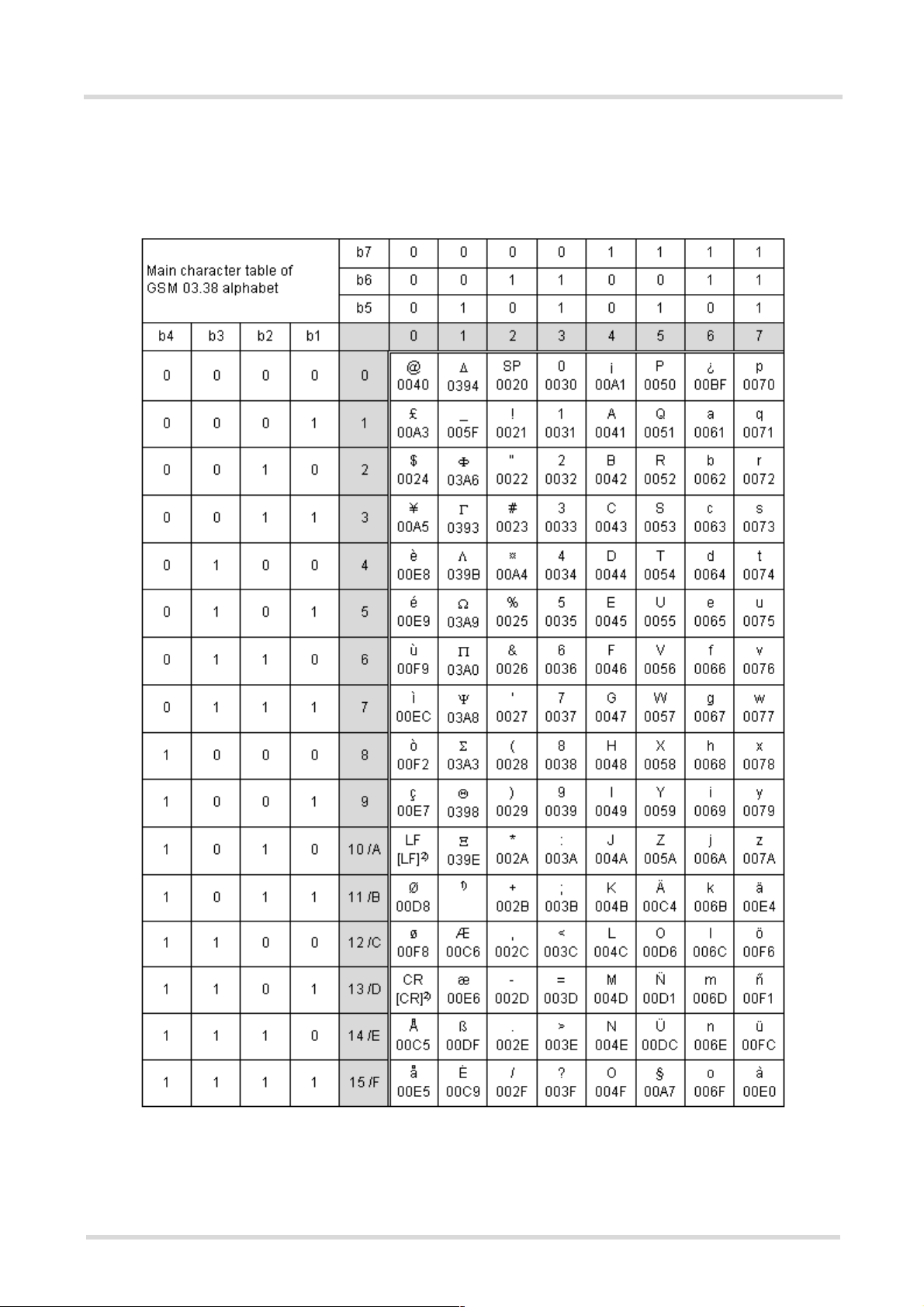
Figure 1.1: Main character table of GSM 03.38 alphabet ............................................................................. 21
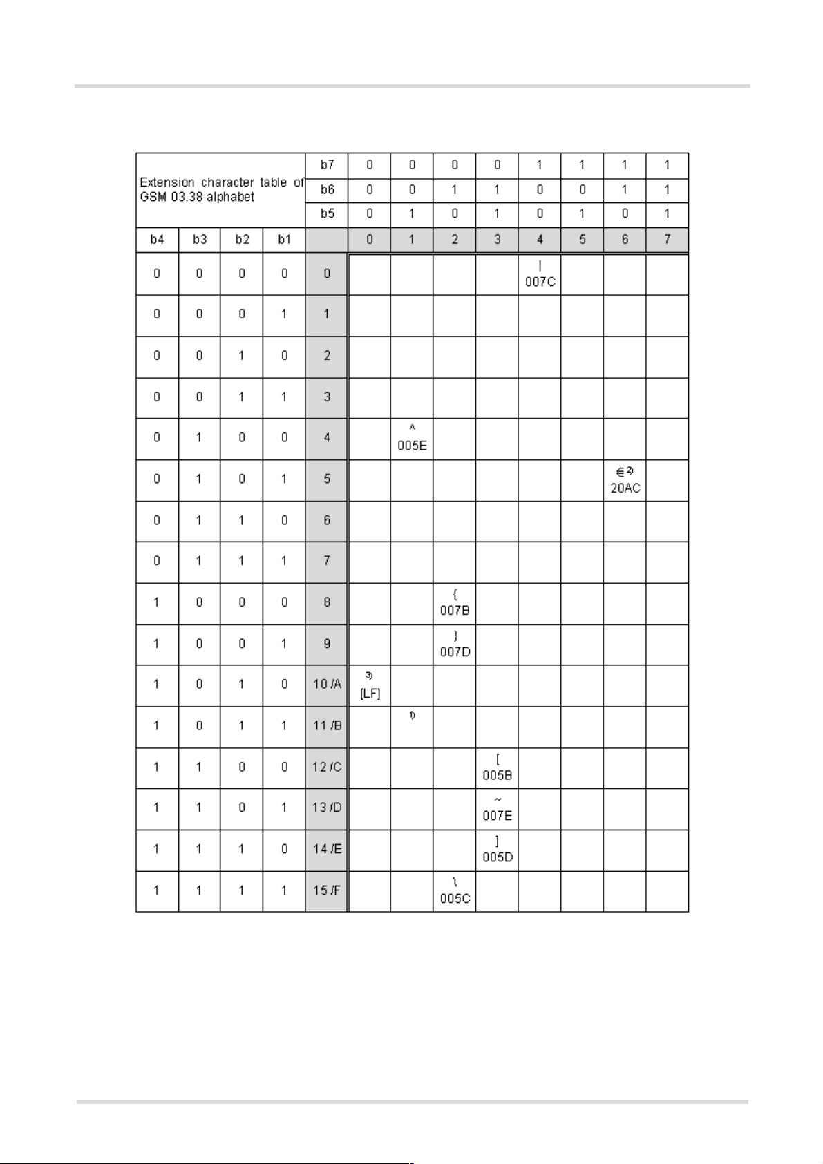
Figure 1.2: Extension character table of GSM 03.38 alphabet ..................................................................... 22
Figure 16.1: Audio programming model........................................................................................................ 392
MC55_ATC_V01.05 Page 12 of 469 2/10/04
Confidential / Released
Page 13

MC55 AT Command Set
1. Introduction
s
m
obil
e
1. Introduction
1.1 Scope of the document
This document presents the AT Command Set for the Siemens Cellular Engine
MC55 Version 01.05.
Before using the Cellular Engine or upgrading to a new firmware version please read the latest product information provided in the Release Notes [1].
More information is available at the Siemens Website: http://www.siemens.com/wm
.
MC55_ATC_V01.05 Page 13 of 469 2/10/04
Confidential / Released
Page 14

MC55 AT Command Set
1.2 Related documents
s
m
obil
e
1.2 Related documents
[1] Release Notes: MC55, Version 01.05
[2] MC55 Hardware Interface Description, Version 01.05
[3] GPRS Startup User's Guide
[4] Remote-SAT User's Guide
[5] Multiplexer User's Guide
[6] Application Note 16: Updating MC55 Firmware
[7] Application Note 02: Audio Interface Design
[8] Multiplex Driver Developer's Guide for Windows 2000 and Windows XP
[9] Multiplex Driver Installation Guide for Windows 2000 and Windows XP
[10] Application Note 22: Using TTY / CTM equipment with MC55
[11] ISO/IEC10646: "Universal Multiple-Octet Coded Character Set (UCS)"; UCS2, 16 bit coding
[12] ITU-T Recommendation V.24: List of definitions for interchange circuits between data terminal equipment
(DTE) and data circuit-terminating equipment (DCE)
[13] ITU-T Recommendation V.25ter: Serial asynchronous automatic dialling and control
[14] 3GPP TS 23.038 (GSM 03.38): Alphabets and language specific information
[15] 3GPP TS 27.005 (GSM 07.05): Use of Data Terminal Equipment - Data Circuit terminating Equipment (DTE
- DCE) interface for Short Message Service (SMS) and Cell Broadcast Service (CBS)
[16] 3GPP TS 27.007 (GSM 07.07): AT command set for User Equipment (UE)
[17] 3GPP TS 27.060 (GSM 07.60): Mobile Station (MS) supporting Packet Switched Services
[18] 3GPP TS 51.011 (GSM 11.11): Specification of the Subscriber Identity Module - Mobile Equipment (SIM -
ME) interface
[19] 3GPP TS 11.14 (GSM 11.14): Specification of the SIM Application Toolkit for the Subscriber Identity Module
- Mobile Equipment (SIM - ME) interface
MC55_ATC_V01.05 Page 14 of 469 2/10/04
Confidential / Released
Page 15

MC55 AT Command Set
1.3 Document conventions
s
m
obil
e
1.3 Document conventions
Throughout the document, the GSM engines are referred to as ME (Mobile Equipment), MS (Mobile Station), TA
(Terminal Adapter), DCE (Data Communication Equipment) or facsimile DCE (FAX modem, FAX board).
To control your GSM engine you can simply send AT Commands via its serial interface. The controlling device
at the other end of the serial line is referred to as TE (Terminal Equipment), DTE (Data Terminal Equipment) or
plainly 'the application' (probably running on an embedded system).
All abbreviations and acronyms used throughout this document are based on the GSM specifications. For definitions please refer to TR 100 350 V7.0.0 (1999-08), (GSM 01.04, version 7.0.0 release 1998).
1.3.1 Quick reference table
Each AT command description includes a table similar to the example shown below. The table is intended as a
quick reference to indicate the following functions:
PIN: Is the AT command PIN protected?
% Yes
! No
§ Usage is dependent on conditions specified for the command, or not all command types are PIN
protected (for example write command PIN protected, read command not).
Note: The table provided in the Chapter Available AT Commands and Dependency on SIM PIN
uses the same symbols.
ASC0: Is the AT command supported on the first physical serial interface ASC0?
% Yes
! No
ASC1: Is the AT command supported on the second physical serial interface ASC1?
% Yes
! No
MUXn: Is the AT command usable on the Multiplexer channels MUX1, MUX2, MUX3?
% Yes
! No
§ AT command is usable, but under the restrictions specified in the chapter related to the com-
mand.
Note: The columns MUX1, MUX2 and MUX3 are relevant only when the GSM engine operates in Mul-
tiplexer mode, that is, when the first physical serial interface is partitioned into 3 virtual channels
by using the Multiplexer protocol. Usage is the same on ASC0 and MUX1.
Example:
PIN ASC0 ASC1 MUX1 MUX2 MUX3
! % % § § §
MC55_ATC_V01.05 Page 15 of 469 2/10/04
Confidential / Released
Page 16

MC55 AT Command Set
1.3 Document conventions
s
1.3.2 Superscript notation for parameters and values
Table 1.1: Symbols used to indicate the correlations with other commands
Parameter option Meaning
<param>
<param>
<param>
<param>
Table 1.2: Symbols used to mark different types of default values of parameters
Value option Meaning
[x] Default value: if the parameter is omitted, the value 'x' will be assumed
(&F)
x
(P)
x
(D)
x
(&W)
(&V)
(ˆSNFW)
(+CSCS)
Parameter value will be stored with AT&W
Parameter value will be displayed with AT&V
Parameter value will be stored with AT^SNFW
Parameter value has to be (is) coded according to current setting of <chset> (see
AT+CSCS for details)
Factory default value, will be restored to 'x' with AT&F
Powerup default value of a parameter which is not stored at power down
Delivery default value of a parameter which cannot be restored automatically
m
obil
e
MC55_ATC_V01.05 Page 16 of 469 2/10/04
Confidential / Released
Page 17

MC55 AT Command Set
1.4 AT command syntax
s
m
obil
e
1.4 AT command syntax
The "AT" or "at" prefix must be set at the beginning of each command line. To terminate a command line enter
<CR>.
Commands are usually followed by a response that includes "
document, only the responses are presented,
Types of AT commands and responses:
AT command type Syntax Function
Test command AT+CXXX=? The mobile equipment returns the
Read command AT+CXXX? This command returns the currently
<CR><LF> are omitted intentionally.
<CR><LF><response><CR><LF>". Throughout this
list of parameters and value ranges
set with the corresponding Write
command or by internal processes.
set value of the parameter or
parameters.
Write command AT+CXXX=<...> This command sets user-definable
parameter values.
Exec(ution) command AT+CXXX The execution command reads
non-variable parameters determined by internal processes in the
GSM engine.
1.4.1 Using parameters
• Optional parameters are enclosed in square brackets. If optional parameters are omitted, the current settings
are used until you change them.
• Optional parameters or subparameters can be omitted unless they are followed by other parameters. If you
want to omit a parameter in the middle of a string it must be replaced by a comma. See also example 1.
• A parameter value enclosed in square brackets represents the value that will be used if an optional parameter
is omitted. See also example 2.
• When the parameter is a character string, e.g.
marks, e.g. "Charlie Brown" or "+49030xxxx". Symbols within quotation marks will be recognized as strings.
• All spaces will be ignored when using strings without quotaton marks.
• It is possible to omit the leading zeros of strings which represent numbers.
• If an optional parameter of a V.25ter command is omitted, its value is assumed to be 0.
<text> or <number>, the string must be enclosed in quotation
MC55_ATC_V01.05 Page 17 of 469 2/10/04
Confidential / Released
Page 18

MC55 AT Command Set
1.4 AT command syntax
Example 1: Omitting parameters in the middle of a string
s
m
obil
e
AT+CCUG?
+CCUG: 1,10,1
OK
AT+CCUG=,9
OK
AT+CCUG?
+CCUG: 1,9,1
OK
Example 2: Using default parameter values for optional parameters
AT+CFUN=5,0
OK
AT+CFUN?
+CFUN: 5
OK
AT+CFUN=
OK
+CFUN: 1
OK
Query current setting
Set only the middle parameter
Query new setting
Activate CYCLIC SLEEP mode, don't reset ME
Query ME mode
Set ME back to normal (default parameters: 1,0)
1.4.2 Combining AT commands on the same command line
You may enter several AT commands on the same line. This eliminates the need to type the "AT" or "at" prefix
before each command. Instead, it is only needed once at the beginning of the command line. Use a semicolon
as command delimiter.
The command line buffer accepts a maximum of 391 characters. If this number is exceeded none of the commands will be executed and TA returns ERROR.
The table below lists the AT commands you cannot enter together with other commands on the same line. Otherwise, the responses may not be in the expected order.
AT command type Comment
V.25ter commands with FAX commands (Prefix AT+F)
GSM 7.07 commands with Siemens commands, Prefix AT^S)
GSM 7.05 commands (SMS) To be used standalone
Commands starting with AT& To be used standalone
AT+IPR To be used standalone
Note: When concatenating AT commands please keep in mind that the sequence of processing may be different
from the sequential order of command input. Therefore, if the consecutive order of the issued commands is your
concern, avoid concatenating commands on the same line.
MC55_ATC_V01.05 Page 18 of 469 2/10/04
Confidential / Released
Page 19

MC55 AT Command Set
1.5 Supported character sets
s
m
obil
e
1.5 Supported character sets
The ME supports two character sets: GSM 03.38 (7 bit, also referred to as GSM alphabet or SMS alphabet) and
UCS2 (16 bit, refer to ISO/IEC 10646). See
tables can be found below.
Explanation of terms
•IRA
IRA means that one byte is displayed as two characters in hexadecimal format. for example, the byte 0x36
(decimal 54) is displayed as "36" (two chars).
• Escape sequences
The escape sequence used within a text coded in the GSM default alphabet (0x1B) must be correctly interpreted by the TE, both for character input and output. To the module, an escape sequence appears like any
other byte received or sent.
•TE
TE is the terminal equipment that uses the GSM default alphabet as its character set. MS Hyperterminal
(often used with the module) is an ANSI / ASCII terminal that does not support the GSM default alphabet.
• Data Coding Scheme
The Data Coding Scheme (dcs) is part of a short message and is saved on the SIM. When writing a short
message to the SIM in textmode, the dcs stored with AT+CSMP is used.
• TE Character Set
The currently used TE character set is selected with AT+CSCS.
AT+CSCS for information about selecting the character set. Character
The behavior when encountering characters, that are not valid characters of the supported alphabets, is undefined.
Due to the constraints described below it is recommended to prefer the USC2 alphabet in any external application.
If the GSM alphabet is selected all characters sent over the serial line are in the range from 0 ... 127. CAUTION:
GSM alphabet is not ASCII alphabet!
Several problems resulting from the use of the GSM alphabet:
• "@" character with GSM alphabet value 0 is not printable by an ASCII terminal program (e.g. Microsoft©
Hyperterminal®).
• "@" character with GSM alphabet value of binary 0 will terminate any C string! This is because the 0 is defined
as C string end tag. Therefore, the GSM Null character may cause problems on application level when using
a 'C'-function as "strlen()". This can be avoided if it is represented by an escape sequence as shown in the
table below.
By the way, this may be the reason why even network providers often replace "@"with "@=*" in their SIM
application.
• Other characters of the GSM alphabet are misinterpreted by an ASCII terminal program. For example, GSM
"ö" (as in "Börse") is assumed to be "|" in ASCII, thus resulting in "B|rse". This is because both alphabets mean
different characters with values hex. 7C or 00 and so on.
• In addition, decimal 17 and 19 which are used as XON/XOFF control characters when software flow control
is activated, are interpreted as normal characters in the GSM alphabet.
When you write characters differently coded in ASCII and GSM (e.g. Ä, Ö, Ü), you need to enter escape
sequences. Such a character is translated into the corresponding GSM character value and, when output later,
the GSM character value can be presented. Any ASCII terminal then will show wrong responses.
Examples for character definitions depending on alphabet
MC55_ATC_V01.05 Page 19 of 469 2/10/04
Confidential / Released
Page 20

MC55 AT Command Set
1.5 Supported character sets
s
m
obil
e
GSM 03.38
character
Ö 5C \ \5C 5C 35 43
" 22 " \22 5C 32 32
ò 08 BSP \08 5C 30 38
@ 00 NULL \00 5C 30 30
CAUTION: Often, the editors of terminal programs do not recognize escape sequences. In this case, an escape
sequence will be handled as normal characters. The most common workaround to this problem is to write a script
which includes a decimal code instead of an escape sequence. This way you can write, for example, short messages which may contain differently coded characters.
GSM character
hex. value
Corresponding
ASCII character
ASCII
Esc sequence
Hex Esc
sequence
MC55_ATC_V01.05 Page 20 of 469 2/10/04
Confidential / Released
Page 21
MC55 AT Command Set
1.5 Supported character sets
s
m
obil
e
1.5.1 GSM alphabet tables and UCS2 character values
This section provides tables for the GSM 03.38 alphabet supported by the ME. Below any GSM character find
the corresponding two byte character value of the UCS2 alphabet.
Figure 1.1: Main character table of GSM 03.38 alphabet
1) This code is an escape to the following extension of the 7 bit default alphabet table.
2) This code is not a printable character and therefore not defined for the UCS2 alphabet. It shall be treated as the accom-
panying control character.
MC55_ATC_V01.05 Page 21 of 469 2/10/04
Confidential / Released
Page 22
MC55 AT Command Set
1.5 Supported character sets
s
m
obil
e
Figure 1.2: Extension character table of GSM 03.38 alphabet
1) This code value is reserved for the extension to another extension table. On receipt of this code, a receiving entity shall
display a space until another extension table is defined.
2) This code represents the EURO currency symbol. The code value is the one used for the character 'e'. Therefore a receiv-
ing entity which is incapable of displaying the EURO currency symbol will display the character 'e' instead.
3) This code is defined as a Page Break character and may be used for example in compressed CBS messages. Any mobile
which does not understand the 7 bit default alphabet table extension mechanism will treat this character as Line Feed.
MC55_ATC_V01.05 Page 22 of 469 2/10/04
Confidential / Released
Page 23

MC55 AT Command Set
1.5 Supported character sets
In the event that an MS receives a code where a symbol is not represented in figure Extension character table
of GSM 03.38 alphabet the MS shall display the character shown in the main default 7 bit alphabet table (see
figure Main character table of GSM 03.38 alphabet).
s
m
obil
e
1.5.2 UCS2 and GSM data coding and conversion for SMS text mode
This chapter provides basic information on how to handle input and output character conversion for SMS text
mode and Remote-SAT if internal (ME) and external (TE) character representation differ, i.e. if the Data Coding
Scheme and the TE character use different coding.
1.5.2.1 Implementing output of SIM data to the TE (direction ME to TE)
dcs
CSCS
GSM Case 1
UCS2 Case 4
Case 1
Every byte will be sent as GSM character (or ASCII with Hyperterminal).
Example: 0x41,0x21 ® "AB" (because of conversion from 7-bit to 8-bit)
Case 2
Every byte will be sent as IRA. No conversion.
Example: 0x41,0x42 ® "4142"
Case 3
Every byte will be sent as IRA. No conversion to GSM to avoid data loss.
Example: 0x00,0x41 ® "0041"
Problems:
• 0x41,0x42 ® "4142" (invalid GSM character, but ignored with respect to GSM 07.05)
• 0x41 ® Error (there are two bytes needed)
7-Bit
(GSM default)
GSM (1:1)
GSM to UCS2 (1:2)
8-Bit 16-Bit
(UCS2)
Case 2
IRA (1:1)
Case 5
GSM to UCS2 (1:2)
Case 3
IRA (2:2)
Case 6
IRA (2:2)
Case 4
Every byte will be converted from GSM to UCS2.
Example: 0x41,0x42 ® "00410042"
Case 5
Every byte will be converted from GSM to UCS2.
Example: 0x41,0x42 ® "00410042"
Case 6
Example: 0x41,0x42 ® "4142"
Problems:
• 0x41 ® Error (there are two bytes needed)
MC55_ATC_V01.05 Page 23 of 469 2/10/04
Confidential / Released
Page 24

MC55 AT Command Set
1.5 Supported character sets
s
m
obil
1.5.2.2 Implementing input of Terminal data to SIM (direction TE to ME)
e
CSCS
dcs
7-Bit
(GSM default)
8-Bit Case 2
16-Bit
(UCS2)
Case 1
Data will be packed to 7-bit.
Maximum text length: 160 characters
Example: "AB" ® 0x41,0x21
Case 2
Data will be saved without any conversion.
Maximum text length: 280 characters
Example: "4142" ® 0x41,0x42
Problems:
• "8f" ® Error (invalid GSM character)
Case 3
Two bytes are needed. No conversion.
Maximum text length: 280 characters
Example: "0041" ® 0x00,0x41
Problems:
• "41" ® Error (there are two bytes needed)
GSM UCS2
Case 1
GSM (1:1)
IRA (1:1)
Case 3
IRA (2:2)
Case 4
UCS2 to GSM (2:1)
Case 5
UCS2 to GSM (2:1)
Case 6
IRA (2:2)
Case 4
Two bytes are needed. Two bytes will be converted to 1 byte GSM and 7-bit packed.
Maximum text length: 640 characters
Example: "00410042" ® 0x41,0x21
Problems:
• "41" ® Error (there are two bytes needed)
• "4142" ® Error (invalid character)
• "0000" ® Error (not an UCS2 character)
• "007B" ® 0x1B,0x28 (the saved data are two bytes long, not 1 byte like in all other cases.
This effects the maximum input length of a string)
Case 5
Two bytes are needed. Two bytes will be converted to 1 byte GSM.
Maximum text length: 560 characters
Example: "00410042" ® 0x41,0x42
Problems:
• "41" ® Error (there are two bytes needed)
• "4142" ® Error (invalid character)
• "0000" ® Error (not an UCS2 character)
• "007B" ® 0x1B,0x28 (the saved data are two bytes long, not 1 byte like in all other cases.
This effects the maximum input length of a string).
MC55_ATC_V01.05 Page 24 of 469 2/10/04
Confidential / Released
Page 25

MC55 AT Command Set
1.5 Supported character sets
Case 6
Two bytes are needed.
Maximum text length: 280 characters
Example: "00410042" ® 0x00,0x41,0x00,0x21
Problems:
• "41" ® Error (there are two bytes needed)
• "0000" ® Error (not an UCS2 character)
• "007B" ® 0x00,0x7B
s
m
obil
e
MC55_ATC_V01.05 Page 25 of 469 2/10/04
Confidential / Released
Page 26

MC55 AT Command Set
1.6 Flow Control
s
m
obil
e
1.6 Flow Control
Flow control is essential to prevent loss of data or avoid errors when, in a data or fax call, the sending device is
transferring data faster than the receiving side is ready to accept. When the receiving buffer reaches its capacity,
the receiving device should be capable to cause the sending device to pause until it catches up.
There are basically two approaches to regulate data flow: software flow control and hardware flow control. The
High Watermark of the input / output buffer should be set to approximately 60% of the total buffer size. The Low
Watermark is recommended to be about 30%. The data flow should be stopped when the capacity rises close to
the High Watermark and resumed when it drops below the Low Watermark. The time required to cause stop and
go results in a hysteresis between the High and Low Watermarks.
In Multiplex mode, it is recommended to use hardware flow control.
1.6.1 Software flow control (XON/OFF flow control)
Software flow control sends different characters to stop (XOFF, decimal 19) and resume (XON, decimal 17) data
flow. The only advantage of software flow control is that three wires would be sufficient on the serial interface.
1.6.2 Hardware flow control (RTS/CTS flow control)
Hardware flow control sets or resets the RTS/CTS wires. This approach is faster and more reliable, and therefore, the better choice. When the High Watermark is reached, CTS is set inactive until the transfer from the buffer
has completed. When the Low Watermark is passed, CTS goes active once again.
To achieve smooth data flow, ensure that the RTS/CTS lines are present on your application platform. The application should include options to enable RTS/CTS handshake with the GSM engine. This needs to be done with
the AT command
The default setting of the GSM engine is
hardware handshake on). The setting is stored volatile and must be restored each time after the GSM engine
was switched off.
AT\Q has no read command. To verify the current setting of AT\Q, simply check the settings of the active profile
with
AT&V.
Often, fax programs run an intialization procedure when started up. The intialization commonly includes enabling
RTS/CTS hardware handshake, eliminating the need to set
CSD call, you are advised to check that RTS/CTS handshake is set.
RTS/CTS hardware handshake must also be set if you want to take advantage of the CYCLIC SLEEP modes.
For further details refer to
Note: After deactivating the RTS line, the ME may still send up to 264 bytes (worst case). This can be easily
handled if the buffer of the host application is sufficiently sized, and if a hysteresis is implemented in its Rx buffer.
For host applications that are required to handle a large amount of data at high speed, a total buffer capacity of
512 bytes is recommended.
AT\Q3 - it is not sufficient to set RTS/CTS handshake in the used Terminal program only.
AT\Q0 (no flow control) which must be altered to AT\Q3 (RTS/CTS
AT\Q3 once again. However, before setting up a
AT+CFUN.
MC55_ATC_V01.05 Page 26 of 469 2/10/04
Confidential / Released
Page 27

MC55 AT Command Set
1.7 Unsolicited Result Code Presentation
s
m
obil
e
1.7 Unsolicited Result Code Presentation
URC stands for Unsolicited Result Code and is a report message issued by the ME without being requested by
the TE, i.e. a URC is issued automatically when a certain event occurs. Hence, a URC is not issued as part of
the response related to an executed AT command.
Typical events leading to URCs are incoming calls ("RING"), received SMs, changing temperature, status of the
battery etc.
A summary of all URCs is given in chapter
To announce a pending URC transmission the ME will do the following:
• Activates its Ring line (logic "1") for one second, i.e. the line changes to physical "Low" level. This allows the
TE to enter power saving mode until ME related events request service.
• If the AT command interface is busy a "BREAK" will be sent immediately but the URC will not be issued until
the line is free. This may happen if the URC is pending
- while an AT command is being processed, i.e. during the time from sending the first character "A" of an
AT command by the TE until the ME has responded with "OK" or "ERROR", or
- during a data call.
Please note that AT command settings may be necessary to enable in-band signaling, e.g. refer to
or AT+CNMI.
It is strongly recommended to use the multiplex mode to map logical communication channels onto the serial line
of the MC55, for details refer to [5] and AT command
process URCs while having a data call active on another.
For most of these messages, the ME needs to be configured whether or not to send an URC. Depending on the
AT command, the URC presentation mode can be saved to the user defined profile (see
activated every time you reboot the ME. Several URCs are not user definable, such as "^SYSSTART",
"^SYSSTART <text>", "
Result Codes (URC)
If autobauding is enabled (as factory default mode or set with
output with 57600 bps until the ME has detected the current bit rate. The URCs "^SYSSTART", "^SYSSTART
<text>", however, are not presented at all. For details please refer to Chapter 4.7.1. To avoid problems we recommend to configure a fixed bit rate rather than using autobauding.
^SHUTDOWN" and the Fax Class 2 URCs listed in Chapter Summary of Unsolicited
.
Summary of Unsolicited Result Codes (URC).
AT+CMER
AT+CMUX. Doing so it is possible to use one channel to still
AT&W), or needs to be
AT+IPR=0), URCs generated after restart will be
1.7.1 Communication between Customer Application and MC55
Leaving hardware flow control unconsidered the Customer Application (TE) is coupled with the MC55 (ME) via
a receive and a transmit line.
Since both lines are driven by independent devices collisions may (and will) happen, i.e. while the TE issues an
AT command the MC55 starts sending an URC. This probably will lead to the TE's misinterpretation of the URC
being part of the AT command's response.
To avoid this conflict the following measures must be taken:
• If an AT command is finished (with "OK" or "ERROR") the TE shall always wait at least 100 milliseconds
before sending the next one.
This gives the MC55 the opportunity to transmit pending URCs and get necessary service.
Note that some AT commands may require more delay after "OK" or "ERROR" response, refer to the following
command specifications for details.
• The TE shall communicate with the MC55 using activated echo (
received from the TE.
Hence, when the TE receives the echo of the first character "A" of the AT command just sent by itself it has
control over both the receive and the transmit paths. This way no URC can be issued by the MC55 in between.
MC55_ATC_V01.05 Page 27 of 469 2/10/04
Confidential / Released
ATE1), i.e. the MC55 echoes characters
Page 28

MC55 AT Command Set
1.8 Common PCN Handset Specification (CPHS)
s
m
obil
e
1.8 Common PCN Handset Specification (CPHS)
The ME provides features to implement a device following the prerequisites of the Common PCN Handset Specification (CPHS) Phase 2.
CPHS Feature Description/Remarks AT command
Alternate Line Service Using two phone numbers with one SIM card. AT^SALS
Voice Message Waiting
Indication
Operator (Service provider) name from SIM
Network and Service Provider Lock
Call Forwarding Get and set diverted call status. Access specific Elementary
Customer Service Profile
(CSP)
Information numbers Hierarchically structured service numbers phonebook on
Indicate the receipt of a short message coded as Voice Message Waiting Indicator as defined by the CPHS Phase 2
standard.
Read specific Elementary Files (6F14h, 6F18h) from SIM. AT+CRSM
Lock/Unlock an ME to specific HPLMN and service provider. AT+CLCK,
File (6F13h) from SIM.
Setting services and their menu entries depending on customer profiles.
SIM according to CPHS 4.2 (mandatory).
AT^SIND,
AT+CMER, indicators
"vmwait1" and
"vmwait2"
(
AT+CPIN)
AT+CCFC, AT+CRSM
AT+CRSM
AT+CRSM
MC55_ATC_V01.05 Page 28 of 469 2/10/04
Confidential / Released
Page 29

MC55 AT Command Set
1.9 Errors and Messages
s
m
obil
e
1.9 Errors and Messages
The final result codes "+CME ERROR: <err>" and "+CMS ERROR: <err>" indicate errors related to mobile equipment or network. The effect is similar to an ERROR result code.
A final result error code terminates the execution of the command and prevents the execution of all remaining
commands that may follow on the same command line. If so, neither ERROR nor OK result code are returned
for these commands. A 30 seconds timeout causes ERROR to be returned when the input of a command is not
complete.
The format of <err> can be either numeric or verbose. This is set with the command
See also:
• 2.11.1
• 2.5.1
•
AT+CEER
AT+CMEE.
MC55_ATC_V01.05 Page 29 of 469 2/10/04
Confidential / Released
Page 30

MC55 AT Command Set
2. Configuration Commands
s
m
obil
e
2. Configuration Commands
The AT Commands described in this chapter allow the external application to determine the MC55's behaviour
under various conditions.
2.1 AT&F Set all current parameters to manufacturer defaults
Syntax
Exec Command
AT&F[<value>]
Response(s)
OK
PIN ASC0 ASC1 MUX1 MUX2 MUX3
! % % % % %
Reference(s)
V.25ter
Command Description
TA sets all current parameters to the manufacturer defined profile.
Parameter Description
<value>
[0] set all TA parameters to manufacturer defaults
Notes
• List of parameters reset to manufacturer default can be found in Chapter Factory Default Settings
Restorable with AT&F
• In addition to the default profile, you can store an individual one with
files enter either
(num)
.
AT&W. To alternate between the two pro-
ATZ (loads user profile) or AT&F (restores factory profile).
• Every ongoing or incoming call will be terminated.
MC55_ATC_V01.05 Page 30 of 469 2/10/04
Confidential / Released
Page 31

MC55 AT Command Set
2.2 AT&V
2.2 AT&V Display current configuration
Syntax
Exec Command
AT&V[<value>]
Response(s)
ACTIVE PROFILE:
... (see section 2.2.1)
OK
PIN ASC0 ASC1 MUX1 MUX2 MUX3
! % § % § §
s
m
obil
e
Reference(s)
V.25ter
Command Description
TA returns the current parameter setting. The configuration varies depending on whether or not PIN authentication has been done and whether or not Multiplex mode is enabled (see
Parameter Description
<value>
[0] Profile number
(num)
AT+CMUX).
Notes
• The parameters of AT^SMGO can only be displayed after the SMS data from the SIM have been read successfully for the first time. Reading starts after successful SIM authentication has been performed, and may take
up to 30 seconds depending on the SIM used. While the read process is in progress, an attempt to read the
parameter will result in empty values.
• The parameter of
AT+CSDH will only be displayed in SMS text mode, see AT+CMGF
2.2.1 AT&V responses
The following tables show four different kinds of responses depending on whether or not the PIN is entered and
whether or not the Multiplex mode is enabled (see
MC55_ATC_V01.05 Page 31 of 469 2/10/04
Confidential / Released
AT+CMUX).
Page 32

MC55 AT Command Set
2.2 AT&V
Table 2.1: Current configuration on ASC0 / MUX channel 1 (example)
PIN authentication done No PIN authentication
s
m
obil
e
ACTIVE PROFILE:
E1 Q0 V1 X4 &C1 &D2 &S0 \Q0
S0:000 S3:013 S4:010 S5:008 S6:000 S7:060 S8:000
S10:002 S18:000
+CBST: 7,0,1
+CRLP: 61,61,78,6
+CR: 0
+FCLASS: 0
+CRC: 0
+CMGF: 0
+CSDH: 0
+CNMI: 0,0,0,0,1
+ILRR: 0
+IPR: 57600
+CMEE: 2
^SMGO: 0,0
+CSMS: 0,1,1,1
^SACM: 0,"000000","000000"
^SLCC: 0
^SCKS: 0,1
+CREG: 0,1
+CLIP: 0,2
+CAOC: 0
+COPS: 0,0,"operator"
+CGSMS: 3
OK
ACTIVE PROFILE:
E1 Q0 V1 X4 &C1 &D2 &S0 \Q0
S0:000 S3:013 S4:010 S5:008 S6:000 S7:060 S8:000
S10:002 S18:000
+CBST: 7,0,1
+CRLP: 61,61,78,6
+CR: 0
+FCLASS: 0
+ILRR: 0
+IPR: 57600
+CMEE: 2
^SCKS: 0,1
OK
Table 2.2: Current configuration on ASC1 and MUX channels 2 and 3 (example)
PIN authentication done No PIN authentication
ACTIVE PROFILE:
E1 Q0 V1 X4 &C1 &D0 &S0 \Q0
S0:000 S3:013 S4:010 S5:008
+CR: 0
+CRC: 0
+CMGF: 0
+CSDH: 0
+CNMI: 0,0,0,0,1
+ILRR: 0
+IPR: 57600
+CMEE: 2
^SMGO: 0,0
+CSMS: 0,1,1,1
^SACM: 0,"000000","000000"
^SLCC: 0
^SCKS: 0,1
+CREG: 0,1
+CLIP: 0,2
+CAOC: 0
+COPS: 0,0,"operator"
+CGSMS: 3
OK
ACTIVE PROFILE:
E1 Q0 V1 X4 &C1 &D0 &S0 \Q0
S0:000 S3:013 S4:010 S5:008
+CR: 0
+ILRR: 0
+IPR: 57600
+CMEE: 2
^SCKS: 0,1
+CGSMS: 3
OK
MC55_ATC_V01.05 Page 32 of 469 2/10/04
Confidential / Released
Page 33

MC55 AT Command Set
2.3 AT&W
s
m
2.3 AT&W Stores current configuration to user defined profile
Syntax
Exec Command
AT&W[<value>]
Response(s)
OK
ERROR/+CME ERROR <err>
PIN ASC0 ASC1 MUX1 MUX2 MUX3
! % % % % %
Reference(s)
V.25ter
obil
e
Command Description
TA stores the currently set parameters to a user defined profile in the non-volatile memory.
Parameter Description
<value>
[0] Number of profile
(num)
Notes
• The user defined profile will be restored automatically after PowerUp. Use ATZ to restore user profile and
AT&F to restore factory settings. Until the first use of AT&W, ATZ works as AT&F.
• User defined profiles in multiplex mode:
AT&W stores the current setting of each channel to the user profile, no matter on which of the three channels
the command is executed. Each channel may have an individual profile.
• A list of parameters stored to the user profile can be found in Chapter
with AT&W
.
AT Command Settings storable
MC55_ATC_V01.05 Page 33 of 469 2/10/04
Confidential / Released
Page 34

MC55 AT Command Set
2.4 ATQ
2.4 ATQ Set result code presentation mode
Syntax
Exec Command
ATQ[<n>]
Response(s)
If <n>=0:
OK
If <n>=1:
(none)
PIN ASC0 ASC1 MUX1 MUX2 MUX3
! % % % % %
s
m
obil
e
Reference(s)
V.25ter
Command Description
This parameter setting determines whether or not the TA transmits any result code to the TE. Information text
transmitted in response is not affected by this setting.
Parameter Description
(num)(&W)(&V)
<n>
(&F)
[0]
1 Result codes are suppressed and not transmitted
DCE transmits result code
MC55_ATC_V01.05 Page 34 of 469 2/10/04
Confidential / Released
Page 35

MC55 AT Command Set
2.5 ATV
s
m
obil
e
2.5 ATV Set result code format mode
This command determines the contents of header and trailer transmitted with AT command result codes and
information responses. Possible responses are described at 2.5.1.
Syntax
Exec Command
ATV[<value>]
Response(s)
If <value>=0
0
If <value>=1
OK
PIN ASC0 ASC1 MUX1 MUX2 MUX3
! % % % % %
Reference(s)
V.25ter
Parameter Description
<value>
[0] Information response: <text><CR><LF>
(&F)
1
(num)(&W)(&V)
Short result code format: <numeric code><CR>
Information response: <CR><LF><text><CR><LF>
Long result code format: <CR><LF><verbose code><CR>
2.5.1 Verbose and numeric result codes
Verbose format Numeric format Meaning
OK 0 Command executed, no errors
CONNECT 1 Link established
RING 2 Ring detected
NO CARRIER 3 Link not established or disconnected
ERROR 4 Invalid command or command line too
long
NO DIALTONE 6 No dial tone, dialling impossible, wrong
mode
BUSY 7 Remote station busy
MC55_ATC_V01.05 Page 35 of 469 2/10/04
Confidential / Released
Page 36

MC55 AT Command Set
2.5 ATV
Verbose format Numeric format Meaning
CONNECT 2400/RLP 47 Link with 2400 bps and Radio Link Pro-
tocol
CONNECT 4800/RLP 48 Link with 4800 bps and Radio Link Pro-
tocol
CONNECT 9600/RLP 49 Link with 9600 bps and Radio Link Pro-
tocol
CONNECT 14400/RLP 50 Link with 14400 bps and Radio Link Pro-
tocol
ALERTING Alerting at called phone
DIALING Mobile phone is dialing
s
m
obil
e
MC55_ATC_V01.05 Page 36 of 469 2/10/04
Confidential / Released
Page 37

MC55 AT Command Set
2.6 ATX
s
m
2.6 ATX Set CONNECT result code format and call monitoring
Syntax
Exec Command
ATX[<value>]
Response(s)
OK
PIN ASC0 ASC1 MUX1 MUX2 MUX3
! % % % % %
Reference(s)
V.25ter
obil
e
Command Description
This parameter setting determines whether or not the TA detects the presence of dial tone and busy signal and
whether or not TA transmits particular result codes.
Parameter Description
<value>
[0] CONNECT result code only returned, dial tone and busy detection are both dis-
1 CONNECT
2 CONNECT
3 CONNECT
(&F)
4
(num)(&W)(&V)
abled.
<text> result code only returned, dial tone and busy detection are
both disabled.
<text> result code returned, dial tone detection is enabled, busy
detection is disabled.
<text> result code returned, dial tone detection is disabled, busy
detection is enabled.
CONNECT <text> result code returned, dial tone and busy detection are both
enabled.
MC55_ATC_V01.05 Page 37 of 469 2/10/04
Confidential / Released
Page 38

MC55 AT Command Set
2.7 ATZ
s
2.7 ATZ Set all current parameters to user defined profile
Syntax
Exec Command
ATZ[<value>]
Response(s)
OK
PIN ASC0 ASC1 MUX1 MUX2 MUX3
! % % % % %
Reference(s)
V.25ter
m
obil
e
Command Description
TA sets all current parameters to the user profile stored with AT&W. If a connection is in progress, it will be terminated.
All defined GPRS contexts which are not activated or not online will be undefined (see
AT+CGQREQ and AT+CGQMIN command).
The user defined profile is stored to the non-volatile memory.
Parameter Description
<value>
[0] Reset to user profile
(num)
AT+CGDCONT,
Notes
• First the profile will be set to factory default (see AT&F). If there is a valid user profile (stored with AT&W), this
profile will be loaded afterwards.
• Any additional commands on the same command line may be ignored. A delay of 300 ms is required before
next command is sent, otherwise "OK" response may be corrupted.
MC55_ATC_V01.05 Page 38 of 469 2/10/04
Confidential / Released
Page 39

MC55 AT Command Set
2.8 AT+CFUN
s
m
obil
e
2.8 AT+CFUN Set phone functionality
This command serves to control the functionality level of the ME. It can be used to reset the ME, to choose one
of the SLEEP modes or to return to full functionality.
Intended for power saving, SLEEP mode reduces the functionality of the ME to a minimum and thus minimizes
the current consumption. SLEEP mode falls in two categories:
• NON-CYCLIC SLEEP mode
• and CYCLIC SLEEP modes, selectable as
NON-CYCLIC SLEEP mode permanently blocks the serial interface. The CYCLIC SLEEP mode, however, is a
dynamic process which alternatingly enables and disables the serial interface. The major benefit of all CYCLIC
SLEEP modes is that the serial interface remains accessible and that, in intermittent wake-up periods, characters
can be sent or received without terminating the selected mode. The best choice is using
since in these modes MC55 automatically resumes power saving, after you have sent or received a short message or made a call.
patibility with earlier releases. In all CYCLIC SLEEP modes, you can enter
MC55 and take it back to full functionality. Please refer to section 2.8.1 for a summary of all SLEEP modes and
the different ways of waking up the module.
For CYCLIC SLEEP mode (
hardware flow control. This is necessary since the CTS signal is set/reset every time when the ME listens to a
paging message from the base station. This is the way how the module indicates to the application when the
UART is active. For detailed information on the timing of the CTS signal refer to [2]. The default setting of hardware flow control is
user profile saved with
If both interfaces ASC0 and ASC1 are connected, hardware flow control must be set in either application.
<fun>=5 or 6 do not offer this feature to the same extent and are only supported for com-
AT\Q0 which must be altered to AT\Q3. For use after restart you are advised to add it to the
AT&W.
<fun>=0
<fun>= 5, 6, 7, 8 or 9.
<fun>= 5, 6, 7, 8 or 9,
<fun>=1 to permanently wake up
<fun>= 5, 6, 7, 8 or 9) both the ME and the application must be configured to use
Syntax
Test Command
AT+CFUN=?
Response(s)
+CFUN: (list of supported <fun>s) , (list of supported <rst>s)
OK
Read Command
AT+CFUN?
Response(s)
+CFUN: <fun>
OK
Write Command
AT+CFUN=[<fun>[, <rst>]]
Response(s)
OK
ERROR
+CME ERROR
MC55_ATC_V01.05 Page 39 of 469 2/10/04
Confidential / Released
Page 40

MC55 AT Command Set
2.8 AT+CFUN
PIN ASC0 ASC1 MUX1 MUX2 MUX3
! % % § § §
Reference(s)
GSM 07.07
Command Description
The test command returns the values of the supported parameters.
The read command returns the current functionality value.
The write command can be used to reset the ME, to choose one of the SLEEP modes or to return to full functionality.
Parameter Description
s
m
obil
e
(&F)
(num)
In this mode, the AT interface is not accessible. Consequently, once you have
set
<fun> level 0, do not send further characters. Otherwise these characters
remain in the input buffer and may delay the output of an unsolicited result
code.
The first wake-up event stops power saving and takes the ME back to full functionality level
Full functionality.
If the ME is in one of the CYCLIC SLEEP modes you can issue AT+CFUN=1
to stop power saving and return to full functionality.
Keep in mind that, unlike the reset command described below, this action does
not restart the ME but only changes the level of functionality. See parameter
<rst> for details on the reset.
In this mode, the serial interface is shortly enabled during paging. If characters
are recognized on the serial interface, the ME stays active for 2 seconds after
the last character was sent or received.
In this mode, the serial interface is shortly enabled during paging.
If characters are recognized on the serial interface, the ME stays active for 10
minutes after the last character was sent or received.
To ensure that power saving takes effect immediately, the ME stays active for
only 2 seconds after
<fun>=1.
<fun>=6 was entered.
<fun>
0 NON-CYCLIC SLEEP mode:
[1]
5 CYCLIC SLEEP mode:
6 CYCLIC SLEEP mode:
7 CYCLIC SLEEP mode:
In this mode, the serial interface is shortly enabled during paging. If characters
are recognized on the serial interface, the ME stays active for 2 seconds after
the last character was sent or received. ME exits SLEEP mode only, if
AT+CFUN=1 is entered.
MC55_ATC_V01.05 Page 40 of 469 2/10/04
Confidential / Released
Page 41

MC55 AT Command Set
2.8 AT+CFUN
8 CYCLIC SLEEP mode:
In this mode, the serial interface is shortly enabled during paging.
If characters are recognized on the serial interface, the ME stays active for 10
minutes after the last character was sent or received. ME exits SLEEP mode
only, if
To ensure that power saving takes effect immediately, the ME stays active for
only 2 seconds after
9 CYCLIC SLEEP mode:
In this mode, the serial interface is shortly enabled during paging. If characters
are recognized on the serial interface, the ME stays active after the last character was sent or received for at least the time, which can be configured by
AT^SCFG="PowerSaver/Mode9/Timeout",<cfun9-timeout> (temporary
wakeup).
In contrast to SLEEP modes 5,6,7 and 8 assertion of RTS can also be used to
temporarily wake up the ME. In this case too, activity time is at least the time
set with
can be activated either from ASC0 or ASC1.
ME exits SLEEP mode only, if
AT+CFUN=1 is entered.
AT^SCFG="PowerSaver/Mode9/Timeout",<cfun9-timeout>. RTS
<fun>=8 was entered.
AT+CFUN=1 is entered.
s
m
obil
e
<rst>
The parameter can only be used if the serial interface is enabled.
Due to the command syntax, you need to enter parameter
placeholder and has no effect. See examples below.
[0] Placeholder for
1 ME resets and restarts to full functionality. After reset and restart, PIN 1
(num)
<fun>, followed by <rst>, where <fun> is only a
<fun> as stated above.
authentication is necessary (
mended to wait 3 to 5 seconds before entering the first AT command. For
details on autobauding refer to chapter "4.7.1".
AT+CPIN). If autobauding is enabled, it is recom-
Notes
• If both serial interfaces ASC0 and ASC1 are connected, any functionality level set with AT+CFUN takes effect
on both of them. In Multiplex mode, the CFUN profile is shared by all multiplexer channels.
• If the ME is in Multiplexer mode, it is not recommended to activate SLEEP mode with
best approach to properly control SLEEP mode in this case is to issue the PSC messages described in [5],
chapter "Power saving control".
• When a circuit-switched call is in progress,
However, setting
• Please keep in mind that power saving works properly only when PIN authentication has been done. If you
attempt to activate power saving while the SIM card is not inserted or the PIN is not correctly entered, the
selected
ing cannot be used if MC55 operates in Alarm mode. Furthermore, in order to accept incoming calls, SMS or
network related URCs in SLEEP mode the ME must be registered when it enters the SLEEP mode.
<fun> level will be set, though power saving does not take effect. For the same reason, power sav-
<fun>=0, 5 or 6 during a circuit-switched call immediately disconnects this call.
<fun>=7 or 8 or 9 can be activated without terminating the call.
AT+CFUN=<fun>. The
• To check whether power saving is on, you can query the status with the read command AT+CFUN? only if
the module is in full functionality mode or in CYCLIC SLEEP mode. If available, you can also take advantage
of the status LED controlled by the SYNC pin (see
ule is in any of the SLEEP modes. However, the module can wake up temporarily from power saving without
leaving its CYCLIC SLEEP mode (without changing +CFUN "
radio coverage, or after receipt of serial data during CYCLIC SLEEP mode. During this "temporary wakeup
state" the LED will operate as if the ME was in full functionality mode.
• Recommendation: In NON-CYCLIC SLEEP mode, you can set an RTC alarm to wake up the ME and return
MC55_ATC_V01.05 Page 41 of 469 2/10/04
Confidential / Released
AT^SSYNC and [2]). The LED remains "off" while the mod-
<fun>"), e.g. for a network scan after a loss of
Page 42

MC55 AT Command Set
2.8 AT+CFUN
to full functionality. This is a useful approach because, in this mode, the AT interface is not accessible.
Examples
EXAMPLE 1
To check the level of functionality use the read command:
AT+CFUN?
+CFUN: 1
Remember that the AT interface is not accessible in NON-CYCLIC SLEEP mode. Consequently, the read
command is only useful when the ME is set to full functionality or, when
AT+CFUN?
+CFUN: 5
EXAMPLE 2
To set the ME to NON-CYCLIC SLEEP mode enter
Default mode after ME was restarted
<fun> is set to 5, 6, 7, 8 or 9.
CYCLIC SLEEP mode
s
m
obil
e
AT+CFUN=0
OK
When, for example, an SMS is being received and indicated by an unsolicited result code (URC), the ME
wakes up to full operation.
+CMTI: "SM",5
Note that the URC used in this example will appear only, if
AT+CNMI=1,1 was configured before.
After this, you may want to verify the operating status:
AT+CFUN?
+CFUN: 1
EXAMPLE 3
Indicates that ME has entered full functionality mode.
To stop CYCLIC SLEEP mode and return to full functionality:
AT+CFUN?
+CFUN: 5
OK
AT+CFUN=1
OK
Remember that this approach is not applicable to the NON-CYCLIC SLEEP mode (since the serial interface
is disabled). The NON-CYCLIC SLEEP mode ends with the first wake-up event.
EXAMPLE 4
To reset and restart the ME:
AT+CFUN=1,1
or alternatively, AT+CFUN=0,1 or 5,1 or 6,1 or 7,1 or 8,1 or 9,1
OK
^SYSSTART
The ^SYSSTART URC confirms that the ME has been rebooted. Note
that ^SYSSTART appears only if
AT+IPR ¹ 0. If the ME is in autobaud
mode, it is recommended to wait 3 to 5 seconds before entering the first
AT command. Remember to enter the SIM PIN after restart.
MC55_ATC_V01.05 Page 42 of 469 2/10/04
Confidential / Released
Page 43

MC55 AT Command Set
2.8 AT+CFUN
s
m
obil
e
2.8.1 Wake up the ME from SLEEP mode
A wake-up event is any event that causes the ME to draw current. Depending on the selected mode, the wakeup event either switches the SLEEP mode off and takes the ME back to full functionality
the ME temporarily without terminating the selected SLEEP mode.
Definitions of the state transitions described in Table 2.3:
• Quit: ME exits SLEEP mode.
• Temporary: ME becomes active temporarily for the duration of the event and the mode-specific follow-up time
after the last character was sent or received on the serial interface.
• No effect: Event is not relevant in the selected SLEEP mode. The ME does not wake up.
Table 2.3: Wake-up events in NON-CYCLIC and CYCLIC SLEEP modes
AT+CFUN=1, or activates
Event Selected mode:
<fun>=0
Ignition line No effect No effect No effect
/RTS0 or /RTS1 activation Quit No effect (RTS is only
Unsolicited Result Code
(URC)
Incoming voice or data
call
Any AT command (incl.
outgoing SMS, voice or
data call)
Incoming SMS (AT+CNMI
is set to 0,0 (this is the
default setting)
Incoming SMS (AT+CNMI
is set to 1,1)
GPRS data transfer Not possible (UART dis-
Quit Quit Temporary
Quit Quit Temporary
Not possible (UART disabled)
No effect No effect No effect
Quit Quit Temporary
abled)
Selected mode:
<fun>=5 or 6
used for flow control)
Temporary Temporary
Temporary Temporary
Selected mode:
<fun>=7 or 8 or 9
Mode 7 and 8: No effect
(RTS is only used for flow
control)
Mode 9: Temporary
RTC alarm line Quit Quit Temporary
AT+CFUN=1 Not possible (UART dis-
abled)
MC55_ATC_V01.05 Page 43 of 469 2/10/04
Confidential / Released
Quit Quit
Page 44

MC55 AT Command Set
2.9 AT^SMSO
2.9 AT^SMSO Switch off mobile station
Syntax
Test Command
AT^SMSO=?
Response(s)
OK
Exec Command
AT^SMSO
Response(s)
^SMSO: MS OFF
OK
s
m
obil
e
PIN ASC0 ASC1 MUX1 MUX2 MUX3
! % % % % %
Reference(s)
SIEMENS
Unsolicited Result Code
^SHUTDOWN
Indicates that the power-off procedure is finished and the module will be switched off within 1 second
Command Description
The exec command initiates the power-off procedure. Low level of the module's VDD pin and display of URC
"
^SHUTDOWN" verifies that the procedure has completed and the module has entered the POWER DOWN mode.
Therefore, be sure not to disconnect the operating voltage until VDD is low or until URC "
played . Otherwise, you run the risk of losing data. For further details on how to turn off the module see the [2].
^SHUTDOWN" is dis-
Notes
• Do not send any command after this command.
• If AT^SMSO is entered on one of the Multiplexer channels the ME closes the Multiplexer channels, terminates
the Multiplexer and deactivates all other functions. Then, the URC "
ical serial interface (ASC0). The URC will be transmitted at the bit rate last activated on ASC0 for use with
the Multiplex driver.
• If both interfaces ASC0 and ASC1 are connected the URC appears on both of them.
MC55_ATC_V01.05 Page 44 of 469 2/10/04
Confidential / Released
^SHUTDOWN" will be issued on the phys-
Page 45

MC55 AT Command Set
2.10 AT+GCAP
2.10 AT+GCAP Request complete TA capabilities list
Syntax
Test Command
AT+GCAP=?
Response(s)
OK
Exec Command
AT+GCAP
Response(s)
+GCAP: <name>
OK
s
m
obil
e
PIN ASC0 ASC1 MUX1 MUX2 MUX3
! % % % % %
Reference(s)
V.25ter
Command Description
TA reports a list of additional capabilities.
Parameter Description
<name>
e.g.: +CGSM,+FCLASS
(str)
Note
• +CGSM: The response text shows which GSM commands of the ETSI standard are supported.
MC55_ATC_V01.05 Page 45 of 469 2/10/04
Confidential / Released
Page 46

MC55 AT Command Set
2.11 AT+CMEE
2.11 AT+CMEE Report mobile equipment error
Syntax
Test Command
AT+CMEE=?
Response(s)
+CMEE: (list of supported<n>s)
OK
Read Command
AT+CMEE?
Response(s)
+CMEE: <n>
OK
s
m
obil
e
Write Command
AT+CMEE=<n>
Response(s)
OK
ERROR
+CME ERROR: <err>
PIN ASC0 ASC1 MUX1 MUX2 MUX3
! % % % % %
Reference(s)
GSM 07.07
Command Description
This command controls the presentation of the result code +CME ERROR: <err> that indicates errors relating to
ME functionality.
When you power down or reset the ME with
2 need to be selected every time you reboot the ME, or may be included, for permanent use, in the user profile
saved with
AT&W.
AT+CFUN=1,1 the setting will be reset to its default. The levels 1 or
Parameter Description
(num)(&W)(&V)
<n>
(&F)
0
1 enable result code and use numeric values
2 enable result code and use verbose values
MC55_ATC_V01.05 Page 46 of 469 2/10/04
Confidential / Released
disable result code (only 'ERROR' will be displayed)
Page 47

MC55 AT Command Set
2.11 AT+CMEE
Notes
• The possible error result codes are listed in 2.11.1, 2.11.2 and 2.11.3.
s
m
obil
e
• In multiplex mode (see
on the other channels may differ.
AT+CMUX) the setting applies only to the logical channel where selected. The setting
Example
To obtain enhanced error messages it is recommended to choose <n>=2.
AT+CMEE=2
OK
2.11.1 Summary of CME ERRORS related to GSM 07.07
Code of <err> Text (if AT+CMEE=2)
0 phone failure
1 no connection to phone
2 phone-adapter link reserved
3 Operation not allowed
4 Operation not supported
5 PH-SIM PIN required
6 PH-FSIM PIN required
7 PH-FSIM PUK required
10 SIM not inserted
11 SIM PIN required
12 SIM PUK required
13 SIM failure
14 SIM busy
15 SIM wrong
16 Incorrect password
17 SIM PIN2 required
18 SIM PUK2 required
20 Memory full
21 invalid index
22 not found
23 Memory failure
24 text string too long
25 invalid characters in text string
26 dial string too long
MC55_ATC_V01.05 Page 47 of 469 2/10/04
Confidential / Released
Page 48

MC55 AT Command Set
2.11 AT+CMEE
Code of <err> Text (if AT+CMEE=2)
27 invalid characters in dial string
30 no network service
31 Network timeout
32 Network not allowed emergency calls only
40 Network personalization PIN required
41 Network personalization PUK required
42 Network subset personalization PIN required
43 Network subset personalization PUK required
44 service provider personalization PIN required
45 service provider personalization PUK required
46 Corporate personalization PIN required
47 Corporate personalization PUK required
s
m
obil
e
48 Master Phone Code required
100 Unknown
132 service option not supported
133 requested service option not subscribed
134 service option temporarily out of order
256 Operation temporary not allowed
257 call barred
258 phone is busy
259 user abort
260 invalid dail string
261 ss not executed
262 SIM blocked
2.11.2 Summary of GPRS-related CME ERRORS
Code of <err> Text (if AT+CMEE=2)
103 Illegal MS
106 Illegal ME
107 GPRS services not allowed
111 PLMN not allowed
112 Location area not allowed
113 Roaming not allowed in this location area
148 unspecified GPRS error
149 PDP authentication failure
150 invalid mobile class
MC55_ATC_V01.05 Page 48 of 469 2/10/04
Confidential / Released
Page 49

MC55 AT Command Set
2.11 AT+CMEE
2.11.3 Summary of CMS ERRORS related to GSM 07.05
Code of <err> Text (if AT+CMEE=2)
1 Unassigned (unallocated) number
8 Operator determined barring
10 Call barred
21 Short message transfer rejected
27 Destination out of service
28 Unidentified subscriber
29 Facility rejected
30 Unknown subscriber
38 Network out of order
41 Temporary failure
s
m
obil
e
42 Congestion
47 Resources unavailable, unspecified
50 Requested facility not subscribed
69 Requested facility not implemented
81 Invalid short message transfer reference value
95 Invalid message, unspecified
96 Invalid mandatory information
97 Message type non-existent or not implemented
98 Message not compatible with short message protocol state
99 Information element non-existent or not implemented
111 Protocol error, unspecified
127 Interworking, unspecified
128 Telematic interworking not supported
129 Short message Type 0 not supported
130 Cannot replace short message
143 Unspecified TP-PID error
144 Data coding scheme (alphabet) not supported
145 Message class not supported
159 Unspecified TP-DCS error
160 Command cannot be actioned
161 Command unsupported
175 Unspecified TP-Command error
176 TPDU not supported
192 SC busy
193 No SC subscription
MC55_ATC_V01.05 Page 49 of 469 2/10/04
Confidential / Released
Page 50

MC55 AT Command Set
2.11 AT+CMEE
Code of <err> Text (if AT+CMEE=2)
194 SC system failure
195 Invalid SME address
196 Destination SME barred
197 SM Rejected-Duplicate SM
198 TP-VPF not supported
199 TP-VP not supported
208 D0 SIM SMS storage full
209 No SMS storage capability in SIM
210 Error in MS
211 Memory Capacity Exceeded
212 SIM Application Toolkit Busy
213 SIM data download error
s
m
obil
e
255 Unspecified error cause
300 ME failure
301 SMS service of ME reserved
302 Operation not allowed
303 Operation not supported
304 Invalid PDU mode parameter
305 Invalid text mode parameter
310 SIM not inserted
311 SIM PIN required
312 PH-SIM PIN required
313 SIM failure
314 SIM busy
315 SIM wrong
316 SIM PUK required
317 SIM PIN2 required
318 SIM PUK2 required
320 Memory failure
321 Invalid memory index
322 Memory full
330 SMSC address unknown
331 no network service
332 Network timeout
340 NO +CNMA ACK EXPECTED
500 Unknown error
512 User abort
MC55_ATC_V01.05 Page 50 of 469 2/10/04
Confidential / Released
Page 51

MC55 AT Command Set
2.11 AT+CMEE
Code of <err> Text (if AT+CMEE=2)
513 unable to store
514 invalid status
515 invalid character in address string
516 invalid length
517 invalid character in pdu
518 invalid parameter
519 invalid length or character
520 invalid character in text
521 timer expired
522 Operation temporary not allowed
s
m
obil
e
MC55_ATC_V01.05 Page 51 of 469 2/10/04
Confidential / Released
Page 52

MC55 AT Command Set
2.12 AT+CSCS
2.12 AT+CSCS Select TE character set
Syntax
Test Command
AT+CSCS=?
Response(s)
+CSCS: (list of supported<chset>s)
OK
Read Command
AT+CSCS?
Response(s)
+CSCS: <chset>
OK
s
m
obil
e
Write Command
AT+CSCS=[<chset>]
Response(s)
OK
PIN ASC0 ASC1 MUX1 MUX2 MUX3
! % % % % %
Reference(s)
GSM 07.07, GSM 11.11
Command Description
Write command informs TA which character set <chset> is used by the TE. TA is then able to convert character
strings correctly between TE and ME character sets.
Parameter Description
(&F)
(str)
GSM default alphabet (GSM 03.38 subclause 6.2.1);
Note: This setting may cause software flow control problems since the codes
used to stop and resume data flow (XOFF = decimal 19, XON = decimal 17)
are interpreted as normal characters.
<chset>
“GSM“
“UCS2“ 16-bit universal multiple-octet coded character set (ISO/IEC10646 [32]); UCS2
character strings are converted to hexadecimal numbers from 0000 to FFFF;
e.g. "004100620063" equals three 16-bit characters with decimal values 65, 98
and 99, $(AT R97)$
MC55_ATC_V01.05 Page 52 of 469 2/10/04
Confidential / Released
Page 53

MC55 AT Command Set
2.12 AT+CSCS
Notes
• Also see chapter "Supported character sets".
• When TA-TE interface is set to 8-bit operation and used TE alphabet is 7-bit, the highest bit will be set to zero.
s
m
obil
e
MC55_ATC_V01.05 Page 53 of 469 2/10/04
Confidential / Released
Page 54

MC55 AT Command Set
2.13 AT^SCFG
s
2.13 AT^SCFG Extended Configuration Setting
Command can be used to query and set various ME parameters.
Parameter names are coded in GSM alphabet, parameter values in the alphabet as specified by
or UCS2).
Syntax
Test Command
AT^SCFG=?
Response(s)
^SCFG: "Audio/AMR", (list of supported <amr>s)
^SCFG: "GPRS/ATS0/withAttach", (list of supported <gaa>s)
^SCFG: "GPRS/RingOnIncomingData", (list of supported <groid>s)
^SCFG: "PowerSaver/Mode9/Timeout", (list of supported <cfun9-timeout> s)
^SCFG: "Radio/Band/HandOver", (list of supported <HandOverStatus>s)
^SCFG: "URC/CallStatus/CIEV", (list of supported <succ>s)
^SCFG: "URC/CallStatus/SLCC", (list of supported <sucs>s)
^SCFG: "URC/Datamode/Ringline", (list of supported <udri>s)
^SCFG: "URC/Ringline", (list of supported <uri>s)
^SCFG: "URC/Ringline/ActiveTime", (list of supported <urat>s)
OK
m
obil
e
AT+CSCS (GSM
Read Command
AT^SCFG?
Response(s)
^SCFG: "Audio/AMR", <amr>
^SCFG: "GPRS/ATS0/withAttach", <gaa>
^SCFG: "GPRS/RingOnIncomingData", <groid>
^SCFG: "PowerSaver/Mode9/Timeout", (list of supported <cfun9-timeout> s)
^SCFG: "Radio/Band/HandOver", <HandOverStatus>
^SCFG: "URC/CallStatus/CIEV", <succ>
^SCFG: "URC/CallStatus/SLCC", <sucs>
^SCFG: "URC/Datamode/Ringline", <udri>
^SCFG: "URC/Ringline", <uri>
^SCFG: "URC/Ringline/ActiveTime", <urat>
OK
Write Command
Adaptive Multi Rate (AMR):
AT^SCFG="Audio/AMR"[, <amr>]
Response(s)
^SCFG: "Audio/AMR", <amr>
OK
ERROR
+CME ERROR: operation temporary not allowed
[, <amr>2[, <amr>3...[<amr>10]]]
1
[, <amr>2[, <amr>3...[<amr>10]]]
1
MC55_ATC_V01.05 Page 54 of 469 2/10/04
Confidential / Released
Page 55

MC55 AT Command Set
2.13 AT^SCFG
s
m
Write Command (Continued)
Adaptive Multi Rate (AMR):
AT^SCFG="Audio/AMR"[, <amr>]
Response(s)
+CME ERROR: invalid index
+CME ERROR: invalid characters in text string
+CME ERROR: unknown
Write Command
GPRS ATS0 with automatic attach
AT^SCFG="GPRS/ATS0/withAttach"[, <gaa>]
Response(s)
^SCFG: "GPRS/ATS0/withAttach", <gaa>
obil
e
Write Command
Ring on incoming GPRS IP data packets
AT^SCFG="GPRS/RingOnIncomingData"[, <groid>]
Response(s)
^SCFG: "GPRS/RingOnIncomingData", <groid>
Write Command
Query/Set timeout value for power saving mode 9
AT^SCFG="PowerSaver/Mode9/Timeout"[, <cfun9-timeout>]
Response(s)
^SCFG: "PowerSaver/Mode9/Timeout", <cfun9-timeout>
Write Command
Control Special Call Handover Setting
AT^SCFG="Radio/Band/HandOver"[, <HandOverStatus>]
Response(s)
^SCFG: "Radio/Band/HandOver", <HandOverStatus>
Write Command
Configuration of URC ""+CIEV":call" Call Status Indication
AT^SCFG="URC/CallStatus/CIEV"[, <succ>]
Response(s)
^SCFG: "URC/CallStatus/CIEV", <succ>
MC55_ATC_V01.05 Page 55 of 469 2/10/04
Confidential / Released
Page 56

MC55 AT Command Set
2.13 AT^SCFG
Write Command
Configuration of URC "^SLCC" Call Status Indication
AT^SCFG="URC/CallStatus/SLCC"[, <sucs>]
Response(s)
^SCFG: "URC/CallStatus/SLCC", <sucs>
Write Command
URC indication in datamode via RING line:
AT^SCFG="URC/Datamode/Ringline"[, <udri>]
Response(s)
^SCFG: "URC/Datamode/Ringline", <udri>
s
m
obil
e
Write Command
URC indication via RING line:
AT^SCFG="URC/Ringline"[, <uri>]
Response(s)
^SCFG: "URC/Ringline", <uri>
Write Command
Duration of active RING line for URC indications:
AT^SCFG="URC/Ringline/ActiveTime"[, <urat>]
Response(s)
^SCFG: "URC/Ringline/ActiveTime", <urat>
PIN ASC0 ASC1 MUX1 MUX2 MUX3
! % % % % %
Reference(s)
SIEMENS
Command Description
The read command returns a list of all supported parameters with their current values.
The write command allows to query a configuration parameter (no value was given) or to set its value(s).
The following error codes are used:
• "+CME ERROR: operation temporary not allowed" ... change of parameter value(s) temporarily not allowed
• "+CME ERROR: invalid index" ... invalid parameter name or invalid value(s).
• "+CME ERROR: invalid characters in text string" ... a character set conversion of parameter value(s) failed
• "+CME ERROR: unknown" ... other errors
MC55_ATC_V01.05 Page 56 of 469 2/10/04
Confidential / Released
Page 57

MC55 AT Command Set
2.13 AT^SCFG
Parameter Description
s
m
obil
e
<amr>
Adaptive Multi Rate
This parameter can be used to control the usage of the feature "Adaptive Multi Rate" (AMR). It is possible to
enable or disable this feature for all network operators, or to enabled it for selected operators (max. 10). If the
feature is enabled for all operators, any request to enable it for a specific operator will result in a "+CME ERROR:
operation temporary not allowed".
Changes of this parameter become active with the next call.
Parameter is global for all interfaces, volatile and will not be reset by
“enabled“ AMR is used for every operator.
“disabled“ AMR is not used for any operator.
00000...999999 Enable AMR for the specified operator (in BCD or IRA format; see
<gaa>
GPRS ATS0 with Attach
This parameter can be used to control the behaviour of
Parameter is global for all interfaces, volatile and will not be reset by
“on“
“off“ When the
(str)(+CSCS)
(str)(+CSCS)
(P)
AT&F.
AT+COPS).
ATS0.
AT&F.
When the ATS0=<n> (<n>>0) command is received, the MT will attempt to perform a GPRS attach.
ATS0=<n> (<n>>0) command is received, the MT will not attempt to
perform a GPRS attach.
(P)
(P)
(str)(+CSCS)
AT&F.
AT+CFUN) and hardware flow control
is in use (
for a GPRS context which is online, then the RING line will be activated once,
for a time which is configured by the parameter "URC/Ringline/ActiveTime"
(
<urat>). The RING line which will be used, can be configured by the param-
eter "URC/Ringline" (
RING line is not activated for incoming IP packets.
(str)(+CSCS)
<fun>=9). The granularity of the timeout value is 100ms (i.e. a value of 10 equals to 1 second). The
...36000
AT\Q3) and RTS line is inactive and there are incoming IP packets
<uri>).
AT+CFUN with
AT&F.
<groid>
Ring on incoming GPRS IP data packets
This parameter can be used to control the behaviour of the RING line for incoming IP packets in GPRS online
mode.
Parameter is local for the interface, volatile and will not be reset by
“on“ If ME is in power saving mode 7 or 8 (see
“off“
<cfun9-timeout>
Power saving mode 9 timeout
This parameter can be used to query or configure the wake up time for power saving mode 9 (see
parameter
minimum timeout value that can be applied is 5, but accuracy is guaranteed for timout values greater than 20
only.
Parameter is global for the ME, volatile and will not be reset by
5...20
MC55_ATC_V01.05 Page 57 of 469 2/10/04
Confidential / Released
Page 58

MC55 AT Command Set
2.13 AT^SCFG
s
m
obil
e
<HandOverStatus>
Call Handover Status
This parameter offers a workaround to prevent problems during call handover into the 1900 MHz (or 1800 MHz)
band, caused by non-conforming configurations of the 1900 MHz (or 1800 MHz) GSM network.
(P)
“0“
“1“ Enable workaround. This value should be selected when handover into a 1900
<uri>
URC RING line
This parameter can be used to control the behaviour of the RING line to indicate URCs (both for idle interfaces
and, if configured by the parameter "URC/Datamode/Ringline", if link is reserved) and, if configured, the indicator
for incoming IP packets (see parameter "GPRS/RingOnIncomingData" (
Parameter is local for the interface, volatile and will not be reset by
“off“ URC is not indicated by RING.
“local“
“asc0“ URC is indicated by an activated RING0 line.
(str)(+CSCS)
(P)
(str)(+CSCS)
Disable workaround.
MHz (or 1800 MHz) GSM network fails. If required for permanent use the value
needs to be set each time the ME is restarted.
<groid>).
AT&F.
URC will be indicated by an activated RING line of the interface on which the
URC appears
(P)
(P)
(str)(+CSCS)
(str)(+CSCS)
<udri>), if link is reserved) and, if con-
AT&F.
RING line will be activated for about 1s.
AT&F.
URC will be indicated by BREAK
parameter "URC/Ringline/ActiveTime" (
used, can be configured by the parameter "URC/Ringline" (
<urat>). The RING line which will be
<uri>).
<urat>
URC RING line Active Time
This parameter can be used to control how long the RING line is activated to indicate URCs (both for idle inter-
faces and, if configured by the parameter "URC/Datamode/Ringline" (
figured by the parameter "GPRS/RingOnIncomingData", to indicate incoming GPRS IP data packets
(
<groid>).
Parameter is global for all interfaces, volatile and will not be reset by
“0“ RING line will be activated for a time between 4.6 and 9.2 ms.
“1“ RING line will be activated for about 100ms.
“2“
<udri>
URC Datamode RING line
This parameter specifies whether RING or BREAK is used for the signaling of URCs when the TA-TE link is
reserved (e.g. during circuit-switched data calls, fax connections, in GPRS data mode or during the execution
of an AT command).
Parameter is global for all interfaces, volatile and will not be reset by
“off“
“on“ URC is indicated by an active RING line for a time which is configured by the
MC55_ATC_V01.05 Page 58 of 469 2/10/04
Confidential / Released
Page 59

MC55 AT Command Set
2.13 AT^SCFG
s
m
obil
e
<succ>
CIEV Call Status Indication
This parameter can be used to control the behaviour of URC "
Call Status Information.
Parameter is global for all interfaces and will not be reset by
“restricted“
“verbose“ URC ""
<sucs>
SLCC Call Status Indication
This parameter can be used to control the behaviour of URC "
Information
Parameter is global for all interfaces and will not be reset by
“restricted“ URC "
“verbose“
(str)(+CSCS)
(P)
(str)(+CSCS)
.
(P)
AT&F.
URC ""+CIEV": call" will be issued only when a Call Status transition ends in
state "active" or "unknown" (see
the list of active calls
+CIEV": call" will be issued when any state transition (including transi-
tions beginning or ending in state "unknown") occurs in the list of active calls,
or when a traffic channel is established
AT&F.
^SLCC" will be issued only when a Call Status transition ends in state
"active" or "unknown" (see
of active calls
URC "^SLCC" will be issued when any state transition (including transitions
beginning or ending in state "unknown") occurs in the list of active calls, or
when a traffic channel is established.
Call Status Information) for a call in the list
+CIEV":call. See also AT+CIND, AT+CMER and
Call Status Information) for a call in
^SLCC". See also AT^SLCC and Call Status
Note
• Parameters "GPRS/ATS0/withAttach" (<gaa>) and "GPRS/RingOnIncomingData" (<groid>) are available
only for modules supporting GPRS.
Examples
EXAMPLE 1
Usage of "Audio/AMR":
AT+CSCS="UCS2"
OK
AT^SCFG?
...
^SCFG:"Audio/AMR","0065006E00610062006C00650064"
...
OK
AT+CSCS="GSM"
OK
AT^SCFG?
...
^SCFG:"Audio/AMR","enabled"
...
Switch to UCS2 character set.
Query all parameters.
AMR will be used for any operator.
MC55_ATC_V01.05 Page 59 of 469 2/10/04
Confidential / Released
Page 60

MC55 AT Command Set
2.13 AT^SCFG
OK
AT^SCFG="Audio/AMR","disabled"
^SCFG:"Audio/AMR","disabled"
OK
AT^SCFG="Audio/AMR","23405"
^SCFG:"Audio/AMR","23405"
OK
AT^SCFG="Audio/AMR","23203"
^SCFG:"Audio/AMR","23405","23203"
OK
AT^SCFG="Audio/AMR"
^SCFG:"Audio/AMR","23405","23203"
OK
s
m
obil
e
AMR is disabled for any operator.
AMR is disabled for any operator, but enabled for
operator "23405".
AMR is disabled for any operator, but enabled for
operators "23405" and "23203".
query parameter "Audio/AMR"
EXAMPLE 2
Usage of "URC/Ringline" and "URC/Datamode/Ringline":
AT+CSCS="GSM"
OK
AT^SCFG?
...
^SCFG:"URC/Datamode/Ringline","off"
^SCFG:"URC/Ringline","local"
...
OK
AT^SCFG="URC/Datamode/Ringline","on"
^SCFG:"URC/Datamode/Ringline","on"
OK
AT^SCFG="URC/Ringline","asc0"
^SCFG:"URC/Ringline","asc0"
OK
AT^SCFG="URC/Datamode/Ringline","off"
^SCFG:"URC/Datamode/Ringline","off"
OK
AT^SCFG="URC/Ringline"
^SCFG:"URC/Ringline","off"
OK
Switch to GSM character set.
Query all parameters.
URCs while TA-TE link is reserved will be indicated
by BREAK.
URCs on this interface will be indicated by RING line
associated to the interface (e.g. RING0 for ASC0).
URCs while TA-TE link is reserved will be indicated
by an activated "local" RING line.
URCs on this (!) interface will be indicated by an activated RING0 regardless whether or not the TA-TE
link is reserved.
URCs on this (!) interface will be indicated by an activated RING0 if TA-TE link is not (!) reserved and by
BREAK if TA-TE link is reserved.
Disable any RING line indication for URCs on this
interface.
MC55_ATC_V01.05 Page 60 of 469 2/10/04
Confidential / Released
Page 61

MC55 AT Command Set
2.14 AT^SM20
2.14 AT^SM20 Set M20 compatibility mode
Syntax
Test Command
AT^SM20=?
Response(s)
OK
Read Command
AT^SM20?
Response(s)
^SM20:<CallMode>, <CmgwMode>
OK
s
m
obil
e
Write Command
AT^SM20=<CallMode>[, <CmgwMode>]
Response(s)
OK
PIN ASC0 ASC1 MUX1 MUX2 MUX3
! % % % % %
Reference(s)
SIEMENS
Command Description
M20 is an earlier, widely used SIEMENS GSM engine. The AT^SM20 command selects different modes of
responses returned upon execution of the commands
that the
between M20 and MC55.
AT^SM20 command has no effect on any other features and is not intended to adjust other differences
ATD and sms commands like e.g. AT+CMGW. Please note
MC55_ATC_V01.05 Page 61 of 469 2/10/04
Confidential / Released
Page 62

MC55 AT Command Set
2.14 AT^SM20
Parameter Description
s
m
obil
e
<CallMode>
Call setup response mode
Applies only to voice calls.
0 Set compatibility to Siemens mobile phones.
(&F)
1
<CmgwMode>
Response mode for sending and writing short messages
Applies to the sms commands like e.g.
0 Set compatibility to Siemens mobile phones.
(&F)
1
(num)
ME will return "OK" immediately after attempting a call with the
In case of failure, additional call release indications, such as "NO DIAL TONE,
"NO CARRIER", "BUSY" will follow.
Default call setup mode, compatible to M20.
ME will return "OK" in case of a successful connection, otherwise one of the
call release indications "NO DIAL TONE, "NO CARRIER", "BUSY" are indicated.
(num)
AT+CMGS and AT+CMGW command.
ME will return +CMS ERROR: <err> when writing or sending of short messages fails.
Default mode for sending and writing short messages, compatible to M20.
ME will return "OK", no matter whether or not sms command was successfully
executed.
ATD command.
MC55_ATC_V01.05 Page 62 of 469 2/10/04
Confidential / Released
Page 63

MC55 AT Command Set
3. Status Control Commands
s
m
obil
e
3. Status Control Commands
The AT Commands described in this chapter allow the external application to obtain various status information
from the MC55.
3.1 AT+CMER Mobile Equipment Event Reporting
This command controls details of the "+CIEV" URC presentation related to AT^SIND and AT+CIND. If registered
via these commands the URCs are sent whenever a value of the related indicator changes.
In addition,
mation
istered indicators will be issued.
Syntax
AT+CMER controls "^SLCC" URCs related to AT^SLCC. For details refer to Call Status Infor-
, AT^SLCC and AT^SCFG, parameter <sucs>. After AT+CMER has been switched on, URCs for all reg-
Test Command
AT+CMER=?
Response(s)
+CMER: (list of supported<mode>s), (list of supported <keyp>s), (list of supported <disp>s), (list of
supported
OK
Read Command
AT+CMER?
Response(s)
+CMER: <mode>, <keyp>, <disp>, <ind>, <bfr>
OK
Write Command
AT+CMER=[<mode>[, <keyp>[, <disp>[, <ind>[, <bfr>]]]]]
Response(s)
OK
ERROR
+CME ERROR
<ind>s), (list of supported <bfr>s)
PIN ASC0 ASC1 MUX1 MUX2 MUX3
% % % % % %
Reference(s)
GSM 07.07
MC55_ATC_V01.05 Page 63 of 469 2/10/04
Confidential / Released
Page 64

MC55 AT Command Set
3.1 AT+CMER
Unsolicited Result Code
+CIEV: <indDescr>, <indValue>
A value of an indicator has changed.
Command Description
The read command returns the URC presentation mode <mode> and among others, the indicator event reporting
status
<ind>.
s
m
obil
e
The write command enables and disables the presentation of "
<indDescr> refers to the name of a "+CIEV" indicator and <indValue> is the new value of this indicator. All
registered indicator events will be issued to the TE.
Parameter Description
<mode>
(&F)
0
1 Discard "
2 Buffer "
3Forward "
<keyp>
(&F)
0
(num)
Discard "+CIEV" and "^SLCC" URCs.
+CIEV" and "^SLCC" URCs when TA-TE link is reserved, e.g. in
online data mode. Otherwise they are forwarded directly to the TE.
+CIEV" and "^SLCC" URCs in the TA while TA-TE link is reserved, e.g.
in online data mode, and flush them to the TE afterwards. Otherwise they are
forwarded directly to the TE.
+CIEV" and "^SLCC" URCs directly to the TE. If MC55 is in online
data mode, URCs are signaled via sending BREAK (100ms) and stored in a
buffer. Once it is back in command mode e.g. after
stored in the buffer will be output.
(num)
Keypad event reporting is not supported by MC55.
+CIEV: <indDescr>, <indValue>" URCs.
+++ was entered, all URCs
<disp>
(&F)
0
<ind>
(&F)
0
2 Enable indicator event reporting.
<bfr>
(&F)
0
<indDescr>
Name of indicator; for a list of all supported indicators please refer to
<indValue>
Value of indicator; for a list of all values for the supported indicators please refer to
MC55_ATC_V01.05 Page 64 of 469 2/10/04
Confidential / Released
(num)
Display event reporting is not supported by MC55.
(num)
Disable indicator event reporting.
(num)
TA buffer of URCs defined within this command is cleared when <mode> 1..3
is entered.
(str)
AT+CIND and AT^SIND.
(num)
AT+CIND and AT^SIND.
Page 65

MC55 AT Command Set
3.1 AT+CMER
Note
• If the ME operates on different instances (MUX channels 1, 2, 3 or ASC0/ASC1) avoid different settings for
routing and indicating SMS. For example, if messages shall be routed directly to one instance of the TE (set
with
AT+CNMI, AT^SSDA), it is not possible to activate the presentation of URCs with AT+CMER or AT+CNMI
on another instance. Any attempt to activate settings that conflict with existing settings on another interface,
will result in CME ERROR, or accordingly CMS ERROR.
s
m
obil
e
MC55_ATC_V01.05 Page 65 of 469 2/10/04
Confidential / Released
Page 66

MC55 AT Command Set
3.2 AT+CIND
s
m
obil
e
3.2 AT+CIND Indicator control
This command controls information about status changes via URC presentation of the MC55 or connected items,
e.g. battery charge level, signal quality, service availability, sound generation, indication of unread short messages, full SMS storage, call in progress or roaming activities.
Use of this command is outdated since additional indications and functionality are available with
AT+CIND supports two ways to get the values related to indicators:
• Query the current status of each indicator by using the read command
matter whether the indicator has been registered with the write command
AT+CIND=[<state>[,<state>[,...]]].
• Evaluate one of the "
of the associated indicator changes.
The presentation of these URCs depends on two settings:
- The indicators must be registered with the write command
default, all of them are registered when the ME is switched on. Any URC can be excluded if deregistered
with
<state>=0.
- URC presentation must be enabled with
+CIEV" URCs which the ME automatically sends to the application, whenever the value
AT+CMER.
AT+CIND?. It returns the status no
AT+CIND=[<state>[,<state>[,...]]]. By
AT^SIND.
Syntax
Test Command
AT+CIND=?
Response(s)
+CIND: (<indDescr>, list of supported <indValue>s)[, (<indDescr>, list of supported <indValue>s)[,
...]]
OK
Read Command
AT+CIND?
Response(s)
+CIND: <indValue>[, <indValue>[, ...]]
OK
ERROR
+CME ERROR: <err>
Write Command
AT+CIND=<state>[, <state>[, ...]]
Response(s)
OK
ERROR
+CME ERROR: <err>
MC55_ATC_V01.05 Page 66 of 469 2/10/04
Confidential / Released
Page 67

MC55 AT Command Set
3.2 AT+CIND
PIN ASC0 ASC1 MUX1 MUX2 MUX3
! % % % % %
Reference(s)
GSM 07.07
Command Description
The read command returns the status of the ME indicators.
The write command is used to switch the event report for each indicator type. The Indicator Event Reports are
displayed to the TE via "
Parameter Description
+CIEV" which can be enabled using AT+CMER.
s
m
obil
e
<indValue>
Integer type value, which shall be in range of corresponding <indDescr>
<indDescr>
String values and their <indValue> ranges.
More indications are available via
mended.
The following indications are accessible via
“battchg“ Battery charge level 0..4 or 5 if no measuring is performed, e.g because no bat-
“signal“ Signal quality (0..7) or (99) if not measurable. The indicated value is the bit
“service“ Service availability (0-1)
“sounder“ Sounder activity (0-1). The indicator provides information about tones gener-
(num)
(str)
AT^SIND. Therefore use of AT^SIND for control of all indications is recom-
AT+CIND:
tery is connected. Also refer
error rate of the signal received. If there are bit errors this is not a constant but
a estimated value which will change in time. See also
0: Not registered to any network
1: Registered to home network or, if "roam"=1 then registered to another network
ated in the ME. Value 1 means for example:
Incoming call - ME is ringing. Note that the URC "
will be output only if ringing tones are activated with
Waiting call - ME generates waiting call tone (if call waiting is enabled).
Outgoing call - ME generates Call Progress tone.
Outgoing call - ME generates BUSY tone.
The value changes to 0 if tone stops
AT^SBC.
AT+CSQ.
+CIEV": "sounder" indicator
AT^SRTC.
“message“ Unread short message at memory location
“call“ Call in progress (0-1). Indicator value is "1" if at least one call is in state "active"
or "held".
Depending on the value of
tor "call" will be issued
• when a state transition ends in state "active" or in state "unknown", if
AT^SCFG setting <succ>="restricted",
• when any state transition (including transitions beginning or ending in state
MC55_ATC_V01.05 Page 67 of 469 2/10/04
Confidential / Released
AT^SCFG setting (refer parameter <succ>), indica-
<mem1> (0-1); refer to AT+CPMS
Page 68

MC55 AT Command Set
3.2 AT+CIND
"unknown") occurs in the list of active calls or when a traffic channel is
established, if
Also refer
“roam“ Roaming indicator (0-1)
0: Registered to home network or not registered
1: Registered to other network
“smsfull“ A short message memory storage in the MT has become full (1) or memory
locations are available (0), i.e. range is (0-1)
“rssi“ Received signal (field) strength (0..5) or (99) if not measurable.
0: signal strength <= -112 dbm
1-4: signal strength in 15 dbm steps
5: signal strength >= -51 dbm
Received signal (field) strength can also be obtained with
the signal strength is scaled to value range 0..31 by this command.
Call Status Information.
AT^SCFG setting <succ>="verbose".
s
m
obil
AT+CSQ. However,
e
<state>
0 Indicator is deregistered. The indicator will not be presented as "
(P)
[1]
(num)
but can be queried with
Indicator is registered, indicator event report allowed.
AT+CIND?.
+CIEV" URC,
Notes
• Due to its restrictive range of values, there are events when it is not entirely clear from the context, which
event has led to the output of indicator "call". Rather than as an information in itself, indicator "call" should
therefore be used as a trigger to look up the new call status in the list of current calls with AT commands
AT^SLCC, AT+CLCC or AT^SCNI.
• If
AT^SCFG setting <succ>="verbose", indicator "call" will be issued also when a traffic channel is estab-
lished, or when a call enters states "terminating" or "dropped" (see chapter
In these cases, the relevant information about the cause of the display is available only from AT command
AT^SLCC.
• The indicator "sounder" signals every event a tone is generated in the ME. For instance, if a waiting call produces a tone, this will be indicated.
• If the ME is switched on all indicators are in registered state.
•Use
AT+CMER command to allow Indicator Event Report of all registered indicators.
Call Status Information).
Example
^SYSSTART
AT+CPIN=9999
OK
AT+CIND?
+CIND: 5,99,1,0,0,0,0,0,5
OK
AT+CMER=2,0,0,2
OK
MC55_ATC_V01.05 Page 68 of 469 2/10/04
Confidential / Released
The battery is either full or no battery is connected to the ME. The bit
error rate of the signal quality is not available (since there is no call in
progress). The ME is registered to its home network.
Now activate the Indicator Event Report with AT+CMER.
Page 69

MC55 AT Command Set
3.2 AT+CIND
+CIEV: battch g, 5
+CIEV: signal ,9 9
+CIEV: servic e, 1
+CIEV: sounde r, 0
+CIEV: messag e, 0
+CIEV: call,0
+CIEV: roam,0
+CIEV: smsful l, 0
+CIEV: rssi,5
ATD0123456;
OK
+CIEV: sounde r, 1
+CIEV: call,1
+CIEV: sounde r, 0
+CIEV: call,0
NO CARRIER
AT+CIND=,,,0,,0
OK
ATD0123456;
OK
NO CARRIER
Receive with full signal field strength.
Make a call.
Receive a set of "+CIEV" URCs reports.
The receiver hangs up.
Deregister the indicators "call" and "sounder".
Rebuild the same call.
This time, no URCs are displayed.
s
m
obil
e
MC55_ATC_V01.05 Page 69 of 469 2/10/04
Confidential / Released
Page 70

MC55 AT Command Set
3.3 AT^SIND
3.3 AT^SIND Extended Indicator Control
AT^SIND supplies extended event indicator control and
• offers greater flexibility than standard
• offers several extra indicators,
• can show the current status of all indicators supported by
• gives the possibility to register or deregister the indicators of both commands,
• displays all indicator event reports via "
Presentation mode of the generated URCs is controlled via
Syntax
Test Command
AT^SIND=?
AT+CIND,
AT+CIND and AT^SIND,
+CIEV" URCs.
AT+CMER.
s
m
obil
e
Response(s)
^SIND: (<indDescr>, list of supported <indValue>s)[, (<indDescr>, list of supported <indValue>s)[,
...]], (list of supported
OK
Read Command
AT^SIND?
Response(s)
^SIND: <indDescr>, <Mode>, <indValue>
OK
ERROR
+CME ERROR: <err>
Write Command
AT^SIND=<indDescr>, <Mode>
Response(s)
OK
ERROR
+CME ERROR: <err>
<Mode>s)
PIN ASC0 ASC1 MUX1 MUX2 MUX3
! % % % % %
Reference(s)
SIEMENS
MC55_ATC_V01.05 Page 70 of 469 2/10/04
Confidential / Released
Page 71

MC55 AT Command Set
3.3 AT^SIND
Command Description
The read command provides a list of all indicators supported by AT+CIND and AT^SIND. Each indicator is represented with its registration mode and current value.
The write command can be used to select a single indicator in order to modify its registration and to view the
current value.
Parameter Description
s
m
obil
e
<indValue>
Integer type value in the range stated below for the corresponding <indDescr>
<indDescr>
String values and their <indValue> ranges.
All indicators supported by
cators can be found there.
The following indicators are accessible via
“audio“ Activity of the internal audio unit (0-1). Value 1 means for example:
“vmwait1“ Voice message waiting indication for line 1, (0-1)
“vmwait2“ Voice message waiting indication for line 2, (0-1)
“ciphcall“ Ciphering Status Change Indication
(num)
(str)
AT+CIND are accessible with this command, too. A detailed description of these indi-
AT^SIND only:
Outgoing voice call: Indicator appears when dialing starts.
Incoming voice call: Indicator appears prior to the RING result code.
As stated in GSM specifications 02.07 and 02.09 the ciphering indicator feature
allows the ME to detect that ciphering is not switched on and to indicate this to
the user.
The ciphering indicator feature may be disabled by the home network operator
setting data in the "administrative data" field (EF
GSM 11.11.
If this feature is not disabled by the SIM, then whenever a connection is in
place, which is, or becomes unenciphered, an indication shall be given to the
user. This enables the user's decision how to proceed.
Read command returns valid ciphering status only if a call is in progress or
active.
If EF
indicates a ciphered link and no URC presentaion will take place.
Note:
The following restrictions apply if the same serial channel is used for
"ciphcall" indication and for the action triggering this URC. In general, the recommended solution is to use a dedicated channel for all status signalling via
URCs.
• If an unciphered mobile originated SMS is performed,
• If an unciphered mobile originated data call is performed,
0 .. Current call or SMS is not ciphered.
1 .. Current call or SMS is ciphered.
setting disables the ciphering indicator feature read command always
AD
URCs on the same serial channel will be issued after the related "OK" and
indicate the ciphering state at this time. Because the SMS is already sent at
this time, you will get 2 URCs on this channel, but both are indicating that
ciphering is enabled.
call" URCs on the same serial channel will be issued after the interface is
not longer blocked by the call (call is released or temporarily stopped) and
indicate the ciphering state at this time.
) in the SIM, as defined in
AD
AT^SIND "ciphcall"
AT^SIND "ciph-
AT^SIND
MC55_ATC_V01.05 Page 71 of 469 2/10/04
Confidential / Released
Page 72

MC55 AT Command Set
3.3 AT^SIND
s
m
obil
e
<Mode>
0 Indicator is deregistered, i.e. no such indicator event report (URC) will be
1 Indicator is registered.
2 Query the registration status and the current value of a single indicator type.
(num)
issued.
• Indicator event reports are controlled via
• Indicators defined by
• On the other hand indicators supported by
the MC55 is powered up.
AT^SIND remain deregistered until explicitly enabled.
AT+CMER.
AT+CIND are registered while
Note
• Notes regarding indicator voice message waiting:
- "vmwait1" and "vmwait2" indicate the receipt of a short message coded as Voice Message Waiting Indicator, as defined by the CPHS Phase 2 standard. The service must be provisioned by the operator.
- The presentation mode of the indicators varies with the operator: If more than one message is received,
some operators only indicate the first one, others deliver the indicator each time a new message is put into
the mail-box.
- The "vmwait" indicators do not apply if a network provider signals, via standard SMS, a message in the
voice mailbox. In this case, the indicator "message" will be displayed (see
- The numbers 1 or 2 in "vmwait1/2" are related to the two lines of the Alternate Line Service (ALS), also
defined in CPHS Phase 2 standard. For further details refer to the
AT^SALS command.
AT+CIND).
MC55_ATC_V01.05 Page 72 of 469 2/10/04
Confidential / Released
Page 73

MC55 AT Command Set
3.4 AT+CEER
3.4 AT+CEER Extended error report
Syntax
Test Command
AT+CEER=?
Response(s)
OK
Exec Command
AT+CEER
Response(s)
+CEER: <locationID>, <reason>, <ssRelease>
OK
s
m
obil
e
PIN ASC0 ASC1 MUX1 MUX2 MUX3
% % % % % %
Reference(s)
GSM 07.07
Command Description
TA returns an extended error report of the reason for the last
•call release
• failure to set up a call (both mobile originated or terminated)
• failure to modify a call by using Supplementary Services
• failed attempt to activate, register, query, deactivate or deregister a Supplementary Service
• unsuccessful GPRS attach or unsuccessful PDP context activation
• GPRS detach or PDP context deactivation
The release cause report is presented in numeric format. A description associated with each number can be
found in the tables given in the following subclauses. The first parameter
other two parameters. Depending on the failure or release cause either
cable.
<locationID> serves to locate the
<reason> or <ssRelease> are appli-
Parameter Description
<locationID>
Location ID as number code. Location IDs are listed in subclause 3.4.1. Each ID is related with another table
that contains a list of
MC55_ATC_V01.05 Page 73 of 469 2/10/04
Confidential / Released
(num)
<reason>s or <ssRelease>s.
Page 74

MC55 AT Command Set
3.4 AT+CEER
s
m
obil
e
<reason>
Reason for last call release as number code. The number codes are listed in several tables, sorted by different
categories in the following subclauses. The tables can be found proceeding from the Location ID given in subclause 3.4.1.
<ssRelease>
Release cause for last Supplementary Service call (listed in subclause 3.4.9) or last call related use of a Supplementary Service (listed in subclause 3.4.10).
(num)
(num)
Notes
• AT+CEER is not available for data calls, please use ATS18=1.
• Default output in the case of a no-error-situation is +CEER: 0,0,0.
<reason> ¹ 0, then <ssRelease> = 0. Vice versa, if <reason> = 0, then <ssRelease> may be ¹ 0.
• If
Examples
EXAMPLE 1
ATD"01751223344";
NO CARRIER
AT+CEER
+CEER: 8,21,0
OK
A mobile originated call is rejected by the remote party.
Call setup is terminated with NO CARRIER.
To check the cause, the caller enters AT+CEER.
The Location ID 8 stated in subclause 3.4.1 points to subclause 3.4.6,
where 21 = "Call rejected". 0 = No error (parameter
is not applicable).
<ssRelease>
EXAMPLE 2
The user attempts to set up a multiparty call, though there are only two parties involved in the present conversation:
ATD"01751223344";
OK
AT+CHLD=2
OK
AT+CHLD=3
+CME ERROR: ope ra t io n te mp or ar y n ot all ow ed
AT+CEER
+CEER: 22,0,2
OK
The Location ID 22 stated in subclause 3.4.1 points to subclause 3.4.10,
where 2 = "Initial conditions not fulfilled (one active, one held call)".
0 = No error (parameter <reason> is not applicable).
MC55_ATC_V01.05 Page 74 of 469 2/10/04
Confidential / Released
Page 75

MC55 AT Command Set
3.4 AT+CEER
EXAMPLE 3
The user attempts to activate call barring. Activation is denied by the network since the password is blocked
after previous failures to enter the password.
AT+clck=oi,1,"0000",3;
+CME ERROR: inc or r ec t pa ss wo rd
AT+CEER
+CEER: 35,0,4 3
OK
The Location ID 35 stated in subclause 3.4.1 points to subclause 3.4.10,
where 43 = "NumberOfPWAttemptsViolation" (for example if wrong
password has been entered 3 times or more). 0 = No error (parameter
<reason> is not applicable).
s
m
obil
3.4.1 Cause Location ID for the extended error report
e
ID Description
0 No error (default)
1 SIEMENS L2 cause
2 GSM cause for L3 Radio Resource Sublayer (GSM 04.08 annex F)
3 SIEMENS cause for L3 Radio Resource Sublayer
4 GSM cause for L3 Mobility Management (GSM 04.08 annex G)
5 SIEMENS cause for L3 Mobility Management
6 GSM cause for L3 Mobility Management via MMR-SAP (GSM 04.08 annex G)
7 SIEMENS cause for L3 Mobility Management via MMR-SAP
8 GSM cause for L3 Call Control (GSM 04.08 10.5.4.11 and annex H)
9 SIEMENS causefor L3 Call Control
11 SIEMENS cause for L3 Advice of Charge Entity
12 GSM cause for L3 SMS CP Entity
13 SIEMENS cause for L3 SMS CP Entity
14 GSM cause for L3 SMS RL Entity
15 SIEMENS cause for L3 SMS RL Entity
16 GSM cause for L3 SMS TL Entity
17 SIEMENS cause for L3 SMS TL Entity
18 SIEMENS cause for DSM Entity
21 GSM cause for L3 Call-related Supplementary Services
22 SIEMENS cause for L3 Call-related Supplementary Services
32 SIEMENS cause for Supplementary Services Entity
33 SIEMENS cause for Supplementary Services Manager
34 Network cause for Supplementary Services (GSM 04.08 10.5.4.11 and annex H)
35 Supplementary Services network error (GSM 04.80 3.6.6)
MC55_ATC_V01.05 Page 75 of 469 2/10/04
Confidential / Released
Page 76

MC55 AT Command Set
3.4 AT+CEER
ID Description
48 GSM cause for GPRS Mobility Management (GSM 04.08 annex G.6)
49 SIEMENS cause for GPRS Mobility Management
50 GSM cause for Session Management (GSM 04.08 annex I)
51 SIEMENS cause for Session Management
127 SIEMENS cause for protocol module or other local cause
128 Supplementary Services general problem (GSM 04.80 3.6.7)
129 Supplementary Services invoke problem (GSM 04.80 3.6.7)
130 Supplementary Services result problem (GSM 04.80 3.6.7)
131 Supplementary Services error problem (GSM 04.80 3.6.7)
241 SIEMENS cause for GPRS API
242 SIEMENS cause for Link Management
243 SIEMENS cause for Embedded Netcore (Internet Protocol Stack)
s
m
obil
e
3.4.2 GSM release cause for L3 Radio Resource (RR)
Number Description
0 Normal event
1 Abnormal release, unspecified
2 Abnormal release, channel unacceptable
3 Abnormal release, timer expired
4 Abnormal release, no activity on the radio path
5 Pre-emptive release
8 Handover impossible, timing advance out of range
9 Channel mode unacceptable
10 Frequency not implemented
65 Call already cleared
95 Semantically incorrect message
96 Invalid mandatory information
97 Message type non-existent or not implemented
98 Message type not compatible with protocol state
100 Conditional information element error
101 No cell allocation available
111 Protocol error unspecified
MC55_ATC_V01.05 Page 76 of 469 2/10/04
Confidential / Released
Page 77

MC55 AT Command Set
3.4 AT+CEER
s
3.4.3 SIEMENS release cause for L3 Radio Resource (RR)
Number Description
1 Racchs not answered
2 Racchs rejected
3 Access class of the SIM is barred by the network provider
4 SABM failure
5 Radio link counter expiry or PerformAbnormalRelease
6 Confirm ABORT of the MM
7 Respond to DEACT REQ
8 Loss of coverage
9 Reestablishment not possible
m
obil
e
3.4.4 GSM release cause for Mobility Management (MM)
Number Description
Causes related to MS identification
2 IMSI unknown in HLR
3 Illegal MS
4 IMSI unknown in VLR
5 IMEI not accepted
6 Illegal ME
Cause related to subscription options
11 PLMN not allowed
12 Location Area not allowed
13 Roaming not allowed in this location area
Causes related to PLMN specific network failures and congestion
17 Network failure
22 Congestion
Causes related to nature of request
32 Service option not supported
33 Requested service option not subscribed
34 Service option temporarily out of order
38 Call cannot be identified
Causes related to invalid messages
95 Semantically incorrect message
96 Invalid mandatory information
97 Message type non-existent or not implemented
MC55_ATC_V01.05 Page 77 of 469 2/10/04
Confidential / Released
Page 78

MC55 AT Command Set
3.4 AT+CEER
Number Description
98 Message not compatible with protocol state
99 Information element non-existent or not implemented
100 Conditional information element error
101 Messages not compatible with protocol state
111 Protocol error, unspecified
Causes related GPRS
7 GPRS services not allowed
8 GPRS services not allowed in combination with non-GPRS services
9 MS identity cannot be identified by the network
10 Implicitly detached
14 GPRS services not allowed in current PLMN
16 MSC temporarily unreachable
s
m
obil
e
3.4.5 SIEMENS release cause for L3 Mobility Management (MM)
Number Description
1 No SIM available
8 No MM connection
9 Authentification failure
11 MM performs detach
17 Registration failed and will be re-attempted in a short term
18 CM connection establishment failed
19 Registration failed and will be re-attempted in a long term
20 RR connection is released
21 MS tries to register
22 SPLMN is not available
23 An MTC is in progress
24 A PLMN scan is in progress
25 The MM is detached, the MS is in MS class C GPRS only
3.4.6 GSM release cause for L3 Call Control (CC)
Number Description
0 No error
Normal class
1 Unassigned (unallocated) number
MC55_ATC_V01.05 Page 78 of 469 2/10/04
Confidential / Released
Page 79

MC55 AT Command Set
3.4 AT+CEER
Number Description
3 No route to destination
6 Channel unacceptable
8 Operator determined barring
16 Normal call clearing
17 User busy
18 No user responding
19 User alerting, no answer
21 Call rejected
22 Number changed
25 Pre-emption
26 Non-selected user clearing
27 Destination out of order
s
m
obil
e
28 Invalid number format (incomplete number)
29 Facility rejected
30 Response to STATUS ENQUIRY
31 Normal, unspecified
Resource unavailable class
34 No circuit/channel available
38 Network out of order
41 Temporary failure
42 Switching equipment congestion
43 Access information discarded
44 Requested circuit/channel not available
47 Resource unavailable, unspecified
Service or option not available class
49 Quality of service unavailable
50 Requested facility not subscribed
55 Incoming calls barred within the CUG
57 Bearer capability not authorized
58 Bearer capability not presently available
63 Service or option not available, unspecified
Service or option not implemented
65 Bearer service not implemented
68 ACM equal or greater than ACMmax
69 Requested facility not implemented
70 Only restricted digital information bearer capability is available
79 service or option not implemented, unspecified
MC55_ATC_V01.05 Page 79 of 469 2/10/04
Confidential / Released
Page 80

MC55 AT Command Set
3.4 AT+CEER
Number Description
Invalid message (e.g. parameter out of range) class
81 Invalid transaction identifier value
87 User not member of CUG
88 Incompatible destination
91 Invalid transit network selection
95 Semantically incorrect message
Protocol error (e.g. unknown message) class
96 Invalid mandatory information
97 Message type non-existant or not implemented
98 Message type not comaptible with protocol state
99 Information element non-existent or not implemented
100 Conditional information element error
s
m
obil
e
101 Message not compatible with protocol
102 Recovery on timer expiry
111 Protocol error, unspecified
Interworking class
127 Interworking, unspecified
3.4.7 SIEMENS release cause for L3 Call Control (CC)
Number Description
1 Call dropped
2 Service not available
3 Hold procedure not available
4 Temporary no service, previous procedure not yet finished
5 No speech service available
6 Call reestablishment procedure active
7 Mobile received a release (complete) message during a modify procedure (modify reject)
8 Call clearing, because loss of radio connection, if no reestablishment is allowed (call not
active)
10 Number not included in FDN list
Notifications
300 Called party barred incoming call
MC55_ATC_V01.05 Page 80 of 469 2/10/04
Confidential / Released
Page 81

MC55 AT Command Set
3.4 AT+CEER
s
3.4.8 SIEMENS release cause for L3 Advice of Charge (AOC)
Number Description
1 SIM data not available
2 SIM does not support AOC
3 SIM data access error
4 ACM limit almost reached ACM range overflow
5 ACM range overflow
3.4.9 GSM Release cause for Supplementary Service Call
Number Description
0 No error (default)
m
obil
e
1 UnknownSubscriber
9 IllegalSubscriber
10 BearerServiceNotProvisioned
11 TeleserviceNotProvisioned
12 IllegalEquipment
13 CallBarred
15 CUGReject
16 IllegalSSOperation
17 SSErrorStatus
18 SSNotAvailable
19 SSSubscriptionViolation
20 SSIncompatibility
21 FacilityNotSupported
27 AbsentSubscriber
29 ShortTermDenial
30 LongTermDenial
34 SystemFailure
35 DataMissing
36 UnexpectedDataValue
37 PWRegistrationFailure
38 NegativePWCheck
43 NumberOfPWAttemptsViolation
71 UnknownAlphabet
72 USSDBusy
126 MaxNumsOfMPTYCallsExceeded
MC55_ATC_V01.05 Page 81 of 469 2/10/04
Confidential / Released
Page 82

MC55 AT Command Set
3.4 AT+CEER
Number Description
127 ResourcesNotAvailable
General Problem Codes
300 Unrecognized Component
301 Mistyped Component
302 Badly Structured Component
Invoke Problem Codes
303 Duplicate Invoke ID
304 Unrecognized Operation
305 Mistyped Parameter
306 Resource Limitation
307 Initiating Release
308 Unrecognized Linked ID
s
m
obil
e
309 Linked Response Unexpected
310 Unexpected Linked Operation
Return Result Problem Codes
311 Unrecognize Invoke ID
312 Return Result Unexpected
313 Mistyped Parameter
Return Error Problem Codes
314 Unrecognized Invoke ID
315 Return Error Unexpected
316 Unrecognized Error
317 Unexpected Error
318 Mistyped Parameter
3.4.10 SIEMENS release cause for Call-related Supplementary Services (CRSS)
Number Description
0 ECT procedure failed (timer expired)
1 Call has been cleared without receiving an answer to ECT request
2 Initial conditions not fulfilled (one active, one held call)
3 Received "return error"
4 Call has been cleared without receiving an answer to CCBS request
5 Initial conditions for CCBS not fulfilled (Idle CRSS)
Causes related to nature of request
25 LLC or SNDCP failure
MC55_ATC_V01.05 Page 82 of 469 2/10/04
Confidential / Released
Page 83

MC55 AT Command Set
3.4 AT+CEER
Number Description
26 Insufficient resources
27 Unknown or missing access point name
28 Unknown PDP address or PDP type
29 User authentification failed
30 Activation rejected by GGSN
31 Activation rejected, unspecified
32 Service option not supported
33 Requested service option not subscribed
34 Service option temporarily out of order
35 NSAPI already used
36 Regular PDP context deactivation
37 QoS not accepted
s
m
obil
e
38 Network failure
39 Reactivation requested
40 Feature not supported
Causes related to invalid messages
81 Invalid transaction identifier value
95 Semantically incorrect message
96 Invalid mandatory information
97 Message type non-existant or not implemented
98 Message type not comaptible with protocol state
99 Information element non-existent or not implemented
100 Conditional information element error
101 Message not compatible with protocol
111 Protocol error, unspecified
3.4.11 SIEMENS release cause for Session Management (SM)
Number Description
3 The MS has not got any answer to the ACTIVATE PDP CONTEXT request message sent five
times to the network
4 A MT PDP context which is active or in the activation process is deactivated because another
MT PDP context with the same TI is requested by the network to be activated
5 A MT PDP context which is active or in the activation process is deactivated because another
MT PDP context with the same TI is requested by the network to be activated. The activation
request is rejected by the SM sending the cause 'insufficient resources' to the network
because the SM was not able to perform the necessary comparisons for a static PDP address
collision detection.
MC55_ATC_V01.05 Page 83 of 469 2/10/04
Confidential / Released
Page 84

MC55 AT Command Set
3.4 AT+CEER
Number Description
6 A MT PDP context which is active or in the activation process is deactivated because another
MT PDP context with the same TI is requested by the network to be activated. As a static PDP
address collision with an MO activating PDP context has been detected by the SM the SM discards the activation request
7 A MT PDP context request has been indicated but could not be processed in time. The acti-
vation request is rejected by the SM sending the cause 'insufficient resources' to the network.
s
m
obil
3.4.12 GSM cause for L3 Protocol module or other local cause
Number Description
2 No detailed cause
e
3.4.13 SIEMENS release cause for GPRS API
Number Description
0 Regular deactivation of the call
1 Action temporarily not allowed
2 Wrong connection type
3 Specified data service profile invalid
4 PDP type or address is unknown
255 Undefined
3.4.14 SIEMENS release cause for Embedded Netcore
Number Description
0 Regular call deactivation
1 LCP stopped
255 Undefined
MC55_ATC_V01.05 Page 84 of 469 2/10/04
Confidential / Released
Page 85

MC55 AT Command Set
3.5 ATS18
3.5 ATS18 Extended call release report
Syntax
Read Command
ATS18?
Response(s)
<n>
OK
Write Command
ATS18=<n>
Response(s)
OK
s
m
obil
e
PIN ASC0 ASC1 MUX1 MUX2 MUX3
! % ! % ! !
Reference(s)
V.25ter
Command Description
This command enables or disables the presentation of extended call release reports for fax and data calls. The
call release report is presented in numeric format and includes the following parameters:
+CAUSE:
If enabled the message will be reported every time a fax or data call is released or fails to be established.
Parameter Description
<n>
An odd number enables the presentation of the extended call release report. An even number disables this feature.
(&F)
0
<locationID>, <reason>
(num)(&W)(&V)
...255
<locationID>
Location ID as number code (see also
Each ID is related to another table that contains a list of
<reason>
Reason for last call release as number code (see also
associated descriptions are listed in several tables, sorted by different categories in Chapter
tables can be found proceeding from the Location IDs listed in 3.4.1.
MC55_ATC_V01.05 Page 85 of 469 2/10/04
Confidential / Released
(num)
<locationID> of AT+CEER). Location IDs are listed in section 3.4.1.
<reason>s.
(num)
<reason> of AT+CEER). <reason> numbers and the
AT+CEER. The
Page 86

MC55 AT Command Set
3.5 ATS18
Note
• The command applies only to circuit switched data and fax calls. For voice calls extended call release reports
can be retrieved using the command
AT+CEER.
Examples
EXAMPLE 1
s
m
obil
e
ATS18=1
OK
ATD03012345678
+CAUSE: 8:17
BUSY
EXAMPLE 2
ATS18=1
OK
ATD03012345678
CONNECT 9600/RLP
Hello,....
+++
+CAUSE: 8:16
NO CARRIER
Enables the presentation of extended call release reports.
Now, a mobile originated data call fails.
An extended error report is output, followed by the result code BUSY.
The Location ID 8 stated in section 3.4.1 points to section 3.4.6, where
17 = "User busy".
Enables the presentation of extended call release reports.
Now, a mobile originated data call is set up.
Call ends after remote party hung up.
Normal call release is reported, followed by the result code NO CAR-
RIER.
The Location ID 8 stated in section 3.4.1 points to section 3.4.6, where
16 = "Normal call clearing".
MC55_ATC_V01.05 Page 86 of 469 2/10/04
Confidential / Released
Page 87

MC55 AT Command Set
3.6 AT+CPAS
3.6 AT+CPAS Mobile equipment activity status
Syntax
Test Command
AT+CPAS=?
Response(s)
+CPAS: (list of supported<pas>s)
OK
Exec Command
AT+CPAS
Response(s)
+CPAS: <pas>
OK
ERROR
+CME ERROR: <err>
s
m
obil
e
PIN ASC0 ASC1 MUX1 MUX2 MUX3
! % % % % %
Reference(s)
GSM 07.07
Command Description
TA returns the activity status of ME.
Parameter Description
<pas>
0 ready
3 incoming call (ringing)
4 call in progress or call hold
(num)
MC55_ATC_V01.05 Page 87 of 469 2/10/04
Confidential / Released
Page 88

MC55 AT Command Set
3.7 AT+WS46
3.7 AT+WS46 Select wireless network
Syntax
Test Command
AT+WS46=?
Response(s)
+WS46: (list of supported<n>s)
OK
Read Command
AT+WS46?
Response(s)
<n>
OK
s
m
obil
e
Write Command
AT+WS46=[<n>]
Response(s)
OK
PIN ASC0 ASC1 MUX1 MUX2 MUX3
! % % % % %
Reference(s)
GSM 07.07
Parameter Description
(num)
<n>
12 GSM digital cellular
MC55_ATC_V01.05 Page 88 of 469 2/10/04
Confidential / Released
Page 89

MC55 AT Command Set
4. Serial Interface Control Commands
s
m
obil
e
4. Serial Interface Control Commands
The AT Commands described in this chapter allow the external application to determine various settings related
to the MC55's serial interface.
4.1 AT\Q Flowcontrol
Syntax
Exec Command
AT\Q[<n>]
Response(s)
OK
If RTS/CTS flow control is not supported by interface and <n> is 2 or 3:
ERROR
PIN ASC0 ASC1 MUX1 MUX2 MUX3
! % % § § §
Reference(s)
V.25ter
Parameter Description
(num)(&W)(&V)
<n>
(&F)
[0]
1 XON/XOFF software flow control
2 only CTS by DCE
3 RTS/CTS hardware flow control
disable flow control
Recommended for the following procedures: incoming or outgoing data calls,
fax calls, MUX mode.
Often, the initialization routine of Fax programs includes enabling RTS/CTS
handshake, eliminating the need to issue
Notes
AT\Q3 once again.
• When using XON/XOFF flow control (AT\Q1) in online mode, +++ should not be used while the data trans-
mission is paused with XOFF. Before entering the command mode with
be resumed using the XON character.
• For compatibility reasons, the
take effect. However, be aware that whenever you use the
save the current configuration to the user profile with
restart.
MC55_ATC_V01.05 Page 89 of 469 2/10/04
Confidential / Released
AT\Q command can be used in Multiplex mode, though the settings will not
AT\Q write command in Multiplex mode and then
AT&W, the changed AT\Q setting will become active after
+++ the paused transmission should
Page 90

MC55 AT Command Set
4.2 AT&C
s
m
4.2 AT&C Set circuit Data Carrier Detect (DCD) function mode
Syntax
Exec Command
AT&C[<value>]
Response(s)
OK
PIN ASC0 ASC1 MUX1 MUX2 MUX3
! % ! % % %
Reference(s)
V.25ter
obil
e
Command Description
This parameter determines how the state of circuit 109(DCD) relates to the detection of received line signal from
the distant end.
Parameter Description
<value>
[0] DCD line is always ON
(&F)
1
(num)(&W)(&V)
DCD line is ON in the presence of data carrier only
MC55_ATC_V01.05 Page 90 of 469 2/10/04
Confidential / Released
Page 91

MC55 AT Command Set
4.3 AT&D
s
m
4.3 AT&D Set circuit Data Terminal Ready (DTR) function mode
Syntax
Exec Command
AT&D[<value>]
Response(s)
OK
PIN ASC0 ASC1 MUX1 MUX2 MUX3
! % § % % %
Reference(s)
V.25ter
obil
e
Command Description
This parameter determines how the TA responds when circuit 108/2 (DTR) is changed from ON to OFF during
data mode.
Parameter Description
<value>
[0] TA ignores status of DTR.
1 ON->OFF on DTR: Change to command mode while retaining the connected
(&F)
2
(num)(&W)(&V)
call.
ON->OFF on DTR: Disconnect data call, change to command mode. During
state DTR = OFF is auto-answer off.
MC55_ATC_V01.05 Page 91 of 469 2/10/04
Confidential / Released
Page 92

MC55 AT Command Set
4.4 AT&S
s
4.4 AT&S Set circuit Data Set Ready (DSR) function mode
Syntax
Exec Command
AT&S[<value>]
Response(s)
OK
PIN ASC0 ASC1 MUX1 MUX2 MUX3
! % ! % % %
Reference(s)
V.25ter
m
obil
e
Command Description
This parameter determines how the TA sets circuit 107 (DSR) depending on the communication state of the TA
interfacing TE.
Parameter Description
<value>
(&F)
[0]
1 TA in command mode: DSR is OFF.
(num)(&W)(&V)
DSR line is always ON
TA in data mode: DSR is ON.
MC55_ATC_V01.05 Page 92 of 469 2/10/04
Confidential / Released
Page 93

MC55 AT Command Set
4.5 ATE
4.5 ATE Enable command echo
Syntax
Exec Command
ATE[<value>]
Response(s)
OK
PIN ASC0 ASC1 MUX1 MUX2 MUX3
! % % % % %
Reference(s)
V.25ter
s
m
obil
e
Command Description
This setting determines whether or not the TA echoes characters received from TE during command state.
Parameter Description
<value>
[0] Echo mode off
(&F)
1
Note
• In case of using the command without parameter, <value> is set to 0.
(num)(&W)(&V)
Echo mode on
MC55_ATC_V01.05 Page 93 of 469 2/10/04
Confidential / Released
Page 94

MC55 AT Command Set
4.6 AT+ILRR
s
m
obil
e
4.6 AT+ILRR Set TE-TA local rate reporting
The command AT+ILRR controls whether or not the intermediate result code "+ILRR" is transmitted from the
DCE to the DTE.
Syntax
Test Command
AT+ILRR=?
Response(s)
+ILRR: (list of supported <value>s)
OK
Read Command
AT+ILRR?
Response(s)
+ILRR: <value>
OK
Write Command
AT+ILRR=<value>
Response(s)
OK
ERROR
+CME ERROR
PIN ASC0 ASC1 MUX1 MUX2 MUX3
% % ! % ! !
Reference(s)
V.25ter
Intermediate Result Code
+ILRR: <rate>
Indicates port rate setting on connection.
Command Description
The write command determines whether or not an intermediate result code of local rate is reported at connection
setup. The rate is reported before the final result code of the connection is transmitted to the TE.
MC55_ATC_V01.05 Page 94 of 469 2/10/04
Confidential / Released
Page 95

MC55 AT Command Set
4.6 AT+ILRR
Parameter Description
s
m
obil
e
<value>
(&F)
0
1 Enables reporting of local port rate
<rate>
port rate setting on connection (bps)
0 Autobauding (see chapter 4.7.1)
300
600
1200
2400
4800
9600
14400
19200
28800
(num)(&W)(&V)
Disables reporting of local port rate
(num)
Not supported on ASC1.
38400
57600
115200
230400
MC55_ATC_V01.05 Page 95 of 469 2/10/04
Confidential / Released
Page 96

MC55 AT Command Set
4.7 AT+IPR
s
4.7 AT+IPR Set fixed local rate
The command AT+IPR can be used to set or query the DTE-DCE interface bitrate.
Syntax
Test Command
AT+IPR=?
Response(s)
+IPR: (list of supported auto-detectable <rate>s) , (list of supported fixed-only <rate>s)
OK
Read Command
AT+IPR?
m
obil
e
Response(s)
+IPR: <rate>
OK
Write Command
AT+IPR=<rate>
Response(s)
OK
ERROR
+CME ERROR
PIN ASC0 ASC1 MUX1 MUX2 MUX3
! % § § § §
Reference(s)
V.25ter
Command Description
The test command returns the values of the supported automatically detectable bitrates and the values of the
supported fixed-bitrates.
The read command returns the current bitrate of the interface.
The write command specifies the bitrate to be used for the interface. When you set a fixed-rate, make sure that
both DTE (TE) and DCE (TA) are configured to the same rate. When you select autobauding, the DCE will automatically recognize the bitrate currently used by the DTE.
A selected bitrate takes effect following the issue of any result code associated with this command (e.g. OK).
The setting is stored in the non-volatile memory and will be used whenever the engine is powered up again. However, in case of autobaud mode (
MC55_ATC_V01.05 Page 96 of 469 2/10/04
Confidential / Released
AT+IPR=0) the detected DCE bitrate will not saved and, therefore, will resyn-
Page 97

MC55 AT Command Set
4.7 AT+IPR
chronized after restarting the GSM engine (see chapter 4.7.1).
Parameter Description
s
m
obil
e
<rate>
bitrate per second (bps)
0 Activate autobauding (see chapter 4.7.1). This is not supported on ASC1.
300
600
1200
2400
4800
9600
14400
19200
28800
38400
57600
115200
230400
(num)(&V)
Notes
• The factory default is autobauding enabled (AT+IPR=0) on ASC0 and 57600bps on ASC1. It will not be
restored with
• The current setting of
not restore the factory setting) or in the event of power failure.
• Generally,
mands on the same command line cannot be avoided, there are several constraints to be considered:
- Avoid combinations with other AT commands.
- Take into account, that a delay of 100ms is required between the response to the last command (e.g. OK)
and the next command on the same line.
- When you enter
received.
- When local echo is active (
following problem: if switching to the new bitrate takes effect while a response is being transmitted, the
last bytes may be sent with the new bitrate and thus, not properly transmitted. The following commands
will be correctly sent at the new bitrate.
• In order to account for greater ammounts of data it is recommended to choose a minimum bitrate of 2400 bps.
If the ME is operated in Multiplex mode we suggest a minimum bitrate of 4800bps.
• When you run the multiplex mode, the write command
the new bitrate will be stored and becomes active, when the module is restarted.
AT&F.
AT+IPR will be preserved when you download firmware (i.e. a firmware update does
AT+IPR should be used as a standalone command. If nethertheless combinations with other com-
AT+IPR=0, autobauding will be activated after the response to the last command is
ATE1) and you enter AT+IPR=x with other commands you may encounter the
AT+IPR=<rate> won't change the current bitrate but
MC55_ATC_V01.05 Page 97 of 469 2/10/04
Confidential / Released
Page 98

MC55 AT Command Set
4.7 AT+IPR
s
m
obil
4.7.1 Autobauding
To take advantage of autobaud mode specific attention must be paid to the following requirements:
• Synchronization between DTE and DCE
Ensure that DTE and DCE are correctly synchronized and the bitrate used by the DTE is detected by the DCE
(ME). To allow the bitrate to be synchronized simply use an "AT" or "at" string. This is necessary
- after you have activated autobauding
- when you start up the GSM engine while autobauding is enabled. It is recommended to wait 3 to 5 seconds
before sending the first AT character. Otherwise undefined characters might be returned.
• Autobauding and autoanswer mode
If you want to use autobauding and autoanswer at the same time, you can easily enable the DTE-DCE synchronization, when you activate autobauding first and then configure the autoanswer mode (
to 0).
The most recently detected baudrate cannot be stored when the GSM engine is powered down. After restart,
the ME will therefore use 57600bps by default, until the first AT character was transmitted and the baudrate
was correctly detected (e.g. to send URCs). This should be taken into account when
user profile (see
• Restrictions on autobauding operation
- The serial interface has to be operated at 8 data bits, no parity and 1 stop bit (this is the factory setting).
- The command
- Only the strings "AT" or "at" can be detected (neither "At" nor "aT").
- The URCs "^SYSSTART", "^SYSSTART ALARM MODE" and "^SYSSTART CHARGE-ONLY MODE" are
not indicated when you start up the ME while autobauding is enabled. This is due to the fact that the new
bitrate is not detected unless DTE and DCE are correctly synchronized as described above.
- Any other URC that may be issued before the ME detects the new bitrate (by receiving the first AT com-
mand string) will be sent at the previous bitrate (57600bps after power up).
- It is not recommended to switch to autobauding from a bitrate that cannot be detected by the the autobaud
mechanism (e.g. 300bps). Responses to
rupted.
- When entering several AT commands on the same line, consider the requirements described above.
• Autobauding and bitrate after restart
The most recently detected bitrate cannot be stored when the ME is powered down (with
fore, the ME will use 57600 bps by default, until the first AT character was transmitted and the bitrate was
correctly detected.
For example, URCs generated after restart will be output with 57600 bps. The same applies to auto-answer
calls if SIM PIN1 authentication is done automatically and autoanswer mode (see
profile stored with
• Autobauding and multiplex mode
If autobauding is active you cannot switch to multiplex mode (see
AT&W) and the ME is restarted if set to autobauding.
A/ cannot be used.
AT+IPR=0 and any commands on the same line might be cor-
ATS0) is enabled in the user
AT&W.
AT+CMUX).
ATS0 not equal
ATS0 is stored to the
AT^SMSO). There-
e
MC55_ATC_V01.05 Page 98 of 469 2/10/04
Confidential / Released
Page 99

MC55 AT Command Set
4.8 AT+CMUX
4.8 AT+CMUX Enter multiplex mode
Syntax
Test Command
AT+CMUX=?
Response(s)
+CMUX: (list of supported<mode>s)
OK
Read Command
AT+CMUX?
Response(s)
+CMUX: <mode>
OK
ERROR
+CME ERROR: <err>
s
m
obil
e
Write Command
AT+CMUX=<mode>
Response(s)
OK
ERROR
+CME ERROR: <err>
PIN ASC0 ASC1 MUX1 MUX2 MUX3
! % % ! ! !
Reference(s)
GSM 07.07, GSM 07.10
Command Description
All information provided in this chapter applies to the ASC0 interface only. The second interface ASC1 has no
support of Multiplex mode.
Multiplex mode according to the ETSI TS 101 669 and GSM 07.10 enables one physical serial asynchronous
interface to be partitioned into three virtual channels. This allows you to take advantage of up to 3 simultaneous
sessions running on the serial interface. For example, you can send or receive data or make a call on the first
channel, while the other two channels are free to control the module with AT commands.
The MC55 module incorporates an internal multiplexer and thus integrates all the functions needed to implement
full-featured multiplex solutions. For the application on top, customers have the flexibility to create their own multiplex programs conforming to the multiplexer protocol. To help system integrators save the time and expense of
designing multiplexer applications, SIEMENS AG offers WinMUX2k, a ready-to-use multiplex driver for Windows
2000 and Windows XP. Another approach is to develop customized solutions based on the sources of the
WinMux2k driver.
MC55_ATC_V01.05 Page 99 of 469 2/10/04
Confidential / Released
Page 100

MC55 AT Command Set
4.8 AT+CMUX
Refer to [5] which provides a detailed description of the multiplex architecture and step-by-step instructions of
how to install and configure the multiplex mode. The WinMUX2k driver and its source files can be supplied on
request. Please contact your local distributor to obtain the latest installation software and user's guide.
Parameter Description
s
m
obil
e
<mode>
Multiplexer transparency mechanism
0 Basic option
<subset>
Subparameters defined in GSM07.07 are adjusted for control and logical channels as follows
0 UIH frames used only (control channel)
(num)
(num)
Notes
• The write command is used to enter the multiplex mode. The setup of the logical channels is initiated by the
TE, i.e. the TE acts as initiator. This means that the TE shall ensure that logical channels are established
before any further actions on the channels can be started.
• There is a timeout of five seconds, if the multiplexer protocol is enabled and no multiplexer control channel is
established. The GSM engine returns to AT command mode.
• The parameter maximum frame size (N1) of
All other parameters are not available.
AT+CMUX in GSM07.10 is fixed to 97 and cannot be changed.
4.8.1 Restrictions on Multiplex mode
When the serial interface ASC0 is in multiplex mode, data and fax calls can only be set up on logical channel 1.
Due to this restriction, AT commands have a different behavior on channels 2+3 compared to channel 1. Several
commands are not available, others return different responses. This chapter summarizes the concerned commands. For general rules and restrictions to be considered in Multiplex mode please refer to [5].
Table 4.1: Availability of AT Commands on Virtual Channels
Command Behavior on channel 1 Behavior on channel 2+3
+++ not usable, but see note
AT+CBST as described not usable
AT+CRLP as described not usable
AT+CG... (GPRS commands) as described see note
AT+F... (Fax commands) as described not usable
AT&S as described not usable
ATA as described no Data Calls
ATD as described no Data Calls
ATDI as described not usable
ATL as described not usable
ATM as described not usable
2)
not usable, but see note
3)
2)
MC55_ATC_V01.05 Page 100 of 469 2/10/04
Confidential / Released
 Loading...