

Page 1

HiPath 8000
optiPoint 410 S V7.0
optiPoint 420 S V7.0
Administrator Manual
Page 2

Safety Precautions
Safety Precautions
Important Notes
Do not operate the telephone in environments where there is
a danger of explosions.
Use only original Siemens accessories. Using other accessories may be dangerous, and will invalidate the warranty and
the CE mark.
Never open the telephone or a key module. If you encounter
any problems, contact System Support.
Attention
7
If the optiPoint 410/420 S V7.0 is supplied with power over the LAN
interface Æ page 232, the power source must be a limited power
source PowerHub compliant with IEC 60950.
• This equipment has been tested and found to comply with the limits
for a Class B digital device, pursuant to Part 15 of the FCC Rules. These
limits are designed to provide reasonable protection against harmful interference when the equipment is operated in a commercial environment.
• This equipment generates, uses, and can radiate radio frequency energy and, if not installed and used in accordance with the instructions,
may cause harmful interference to radio communications.
Operation of this equipment in a residential area is likely to cause harmful interference, in which case the user will be required to correct the
interference at his own expense.
• The IP telephone optiPoint 410/420 S V7.0 complies with the European
standard EN 60 950.
• The earpiece in this telephone handset contains a magnet. To prevent
injury, before each use ensure objects such as pins or staples are not
stuck to the earpiece.
• There is always the danger of small objects being swallowed by young
children. In the case of the optiPoint 410/420 S V7.0, this applies in particular to the connecting cord clip.
Please make sure that such items are not accessible to children.
• Never allow the telephone to come into contact with staining or corrosive liquids, such as coffee, tea, juice or soft drinks.
The information provided in this document contains merely general descriptions or characteristics of performance features which in case of actual use do not always apply as described or which may change as a result
of further development of the products.
2
Page 3

Safety Precautions
An obligation to provide the respective performance features only exists if
expressly agreed in the terms of contract.
Note! (for U.S.A and Canada only)
This equipment has been tested and found to comply with the limits
for a Class B digital device, pursuant to Part 15 of the FCC Rules.
These limits are designed to provide reasonable protection against
harmful interference when the equipment is operated in a residential installation. This equipment generates, uses, and can radiate radio frequency energy and, if not installed and used in accordance
with the instructions, may cause harmful interference to radio communications. However, there is no guarantee that interference will
not occur in a particular installation. If this equipment does cause
harmful interference to radio or television reception, which can be
determined by turning the equipment off and on, the user is encouraged to try to correct the interference by one or more of the following measures:
• Reorient or relocate the receiving antenna.
• Increase the separation between the equipment and receiver.
• Connect the equipment into an outlet on a circuit different from
that to which the receiver is connected.
• Consult the dealer or an experienced radio/TV technician for
help.
This product is a UL Listed Accessory, I.T.E., in U.S.A. and Canada.
Location of the Telephone
• The telephone should be operated in a controlled environment with an
ambient temperature between 5 °C and 40 °C (41 °F and 104 °F).
• To ensure good handsfree talking quality, the area in front of the microphone (front right) should be kept clear. The optimum handsfree distance is 20 inches (50cm).
• Do not install the telephone in a room where large quantities of dust
accumulate; this can considerably reduce the service life of the telephone.
• Do not expose the telephone to direct sunlight or any other source of
heat, as this is liable to damage the electronic equipment and the plastic casing.
• Do not operate the telephone in damp environments such as bathrooms.
Telephone Maintenance
• Always use a damp or antistatic cloth to clean the telephone. Never
use a dry cloth.
• If the telephone is very dirty, clean it with a diluted neutral cleaner containing some form of surfactant, such as a dish detergent. Afterwards,
remove all traces of the cleaner with a damp cloth (using water only).
• Never use cleaners containing alcohol, cleaners that corrode plastic, or
abrasive powders.
3
Page 4

Safety Precautions
Labels
The device conforms to the EU guideline 1999/5/EG, as attested by the CE mark.
This device has been manufactured in accordance with our
certified environmental management system (ISO 14001).
This process ensures that energy consumption and the use
of primary raw materials are kept to a minimum, thus reducing waste production.
All electrical and electronic products should be disposed of
separately from the municipal waste stream via designated
collection facilities appointed by the government or the local
authorities.
The correct disposal and separate collection of your old appliance will help prevent potential negative consequences
for the environment and human health. It is a precondition
for reuse and recycling of used electrical and electronic
equipment.
For more detailed information about disposal of your old appliance, please contact your city office, waste disposal service, the shop where you purchased the product or your sales representative.
The statements quoted above are only fully valid for equipment which is installed and sold in the countries of the European Union and is covered by the directive 2002/96/EC.
Countries outside the European Union may have other regulations regarding the disposal of electrical and electronic
equipment.
4
Page 5

Contents
Contents
Safety Precautions . . . . . . . . . . . . . . . . . . . . . . . . . . . .2
General Information . . . . . . . . . . . . . . . . . . . . . . . . . . 15
About the Manual . . . . . . . . . . . . . . . . . . . . . . . . . . . . . . . . . . . . . . . . . 15
Symbols in the Manual . . . . . . . . . . . . . . . . . . . . . . . . . . . . . . . . . . 16
Operating the telephone . . . . . . . . . . . . . . . . . . . . . . . . . . . . . . . . . 17
Intended Use. . . . . . . . . . . . . . . . . . . . . . . . . . . . . . . . . . . . . . . . . . . . . 18
Product Identification. . . . . . . . . . . . . . . . . . . . . . . . . . . . . . . . . . . . . . . 18
Application Version . . . . . . . . . . . . . . . . . . . . . . . . . . . . . . . . . . . . . . . . 18
Service. . . . . . . . . . . . . . . . . . . . . . . . . . . . . . . . . . . . . . . . . . . . . . . . . . 18
Installation . . . . . . . . . . . . . . . . . . . . . . . . . . . . . . . . . . 19
Prerequisites . . . . . . . . . . . . . . . . . . . . . . . . . . . . . . . . . . . . . . . . . . . . . 19
Connecting to the Network . . . . . . . . . . . . . . . . . . . . . . . . . . . . . . . . . . 19
Installing the Phone . . . . . . . . . . . . . . . . . . . . . . . . . . . . . . . . . . . . . . . . 20
Starting up the optiPoint 410/420 S V7.0. . . . . . . . . . . . . . . . . . . . . 21
Mini Switch . . . . . . . . . . . . . . . . . . . . . . . . . . . . . . . . . . . . . . . . . . . . . . 22
Power over LAN information . . . . . . . . . . . . . . . . . . . . . . . . . . . . . . . . . 22
Startup Procedure . . . . . . . . . . . . . . . . . . . . . . . . . . . . . . . . . . . . . . . . . 23
Using the optiPoint 410/420 family S V7.0 . . . . . . . . 24
Properties of the optiPoint 410/420 Telephone Models . . . . . . . . . . . . 24
Telephone Modes . . . . . . . . . . . . . . . . . . . . . . . . . . . . . . . . . . . . . . 24
Control panel . . . . . . . . . . . . . . . . . . . . . . . . . . . . . . . . . . . . . . . . . . . . . 25
Display and Dialog Keys . . . . . . . . . . . . . . . . . . . . . . . . . . . . . . . . . . . . 27
Dialling Keypad . . . . . . . . . . . . . . . . . . . . . . . . . . . . . . . . . . . . . . . . . . . 28
Programmable Keys . . . . . . . . . . . . . . . . . . . . . . . . . . . . . . . . . . . . . . . 29
Control Keys . . . . . . . . . . . . . . . . . . . . . . . . . . . . . . . . . . . . . . . . . . . . . 30
Phone Features . . . . . . . . . . . . . . . . . . . . . . . . . . . . . .31
Protocol support . . . . . . . . . . . . . . . . . . . . . . . . . . . . . . . . . . . . . . . . . . 31
Capabilities . . . . . . . . . . . . . . . . . . . . . . . . . . . . . . . . . . . . . . . . . . . . . . 31
Network . . . . . . . . . . . . . . . . . . . . . . . . . . . . . . . . . . . . . . . . . . . . . . 31
Configuration . . . . . . . . . . . . . . . . . . . . . . . . . . . . . . . . . . . . . . . . . . 31
Management . . . . . . . . . . . . . . . . . . . . . . . . . . . . . . . . . . . . . . . . . . 31
Speech. . . . . . . . . . . . . . . . . . . . . . . . . . . . . . . . . . . . . . . . . . . . . . . 32
Call Features . . . . . . . . . . . . . . . . . . . . . . . . . . . . . . . . . . . . . . . . . . . . . 32
DTMF . . . . . . . . . . . . . . . . . . . . . . . . . . . . . . . . . . . . . . . . . . . . . . . . . . 33
5
Page 6

Contents
Technical Overview. . . . . . . . . . . . . . . . . . . . . . . . . . .34
Session Initiation Protocol (SIP). . . . . . . . . . . . . . . . . . . . . . . . . . . . . . . 34
Overview . . . . . . . . . . . . . . . . . . . . . . . . . . . . . . . . . . . . . . . . . . . . . 34
SIP Functions. . . . . . . . . . . . . . . . . . . . . . . . . . . . . . . . . . . . . . . . . . 34
Components in a SIP system. . . . . . . . . . . . . . . . . . . . . . . . . . . . . . 35
Registration . . . . . . . . . . . . . . . . . . . . . . . . . . . . . . . . . . . . . . . . . . . 37
IP Network Protocols. . . . . . . . . . . . . . . . . . . . . . . . . . . . . . . . . . . . . . . 38
DHCP . . . . . . . . . . . . . . . . . . . . . . . . . . . . . . . . . . . . . . . . . . . . . . . . 38
DNS . . . . . . . . . . . . . . . . . . . . . . . . . . . . . . . . . . . . . . . . . . . . . . . . . 41
SNTP . . . . . . . . . . . . . . . . . . . . . . . . . . . . . . . . . . . . . . . . . . . . . . . . 43
SNMP . . . . . . . . . . . . . . . . . . . . . . . . . . . . . . . . . . . . . . . . . . . . . . . 43
IP Network Configuration . . . . . . . . . . . . . . . . . . . . . . . . . . . . . . . . . . . 44
Routing . . . . . . . . . . . . . . . . . . . . . . . . . . . . . . . . . . . . . . . . . . . . . . 44
Virtual LAN (VLAN). . . . . . . . . . . . . . . . . . . . . . . . . . . . . . . . . . . . . . 44
DLS . . . . . . . . . . . . . . . . . . . . . . . . . . . . . . . . . . . . . . . . . . . . . . . . . 45
Quality of Service (QoS). . . . . . . . . . . . . . . . . . . . . . . . . . . . . . . . . . 46
Secure Payload . . . . . . . . . . . . . . . . . . . . . . . . . . . . . . . . . . . . . . . . 46
Administration Interfaces. . . . . . . . . . . . . . . . . . . . . .47
Phone Menu . . . . . . . . . . . . . . . . . . . . . . . . . . . . . . . . . . . . . . . . . . . . . 47
Web Interface . . . . . . . . . . . . . . . . . . . . . . . . . . . . . . . . . . . . . . . . . . . . 47
Basic Administration. . . . . . . . . . . . . . . . . . . . . . . . . .48
Access to the Phone Administrator and Diagnostics Menu . . . . . . . . . 48
Administrator menu . . . . . . . . . . . . . . . . . . . . . . . . . . . . . . . . . . . . . 48
Diagnostics menu . . . . . . . . . . . . . . . . . . . . . . . . . . . . . . . . . . . . . . 49
Basic Configuration . . . . . . . . . . . . . . . . . . . . . . . . . . . . . . . . . . . . . . . . 50
optiPoint 410/420 economy/economy plus/standard/advance . . . . 50
optiPoint 410 entry . . . . . . . . . . . . . . . . . . . . . . . . . . . . . . . . . . . . . 53
Extended Administration . . . . . . . . . . . . . . . . . . . . . .57
Configure Network Parameters. . . . . . . . . . . . . . . . . . . . . . . . . . . . . . . 57
Network Addresses. . . . . . . . . . . . . . . . . . . . . . . . . . . . . . . . . . . . . 57
Quality of Service (QoS). . . . . . . . . . . . . . . . . . . . . . . . . . . . . . . . . . 58
Configure LAN Ports . . . . . . . . . . . . . . . . . . . . . . . . . . . . . . . . . . . . 60
Configure System Information . . . . . . . . . . . . . . . . . . . . . . . . . . . . . . . 61
Terminal Details . . . . . . . . . . . . . . . . . . . . . . . . . . . . . . . . . . . . . . . . 61
SIP Specific Configuration . . . . . . . . . . . . . . . . . . . . . . . . . . . . . . . . 62
SIP Features . . . . . . . . . . . . . . . . . . . . . . . . . . . . . . . . . . . . . . . . . . 64
Miscellaneous . . . . . . . . . . . . . . . . . . . . . . . . . . . . . . . . . . . . . . . . . 66
Configuring Date and Time . . . . . . . . . . . . . . . . . . . . . . . . . . . . . . . . . . 67
SNTP is available, but no automatic access by DHCP server . . . . . 67
No SNTP server available. . . . . . . . . . . . . . . . . . . . . . . . . . . . . . . . . 67
6
Page 7

Contents
Multiline. . . . . . . . . . . . . . . . . . . . . . . . . . . . . . . . . . . . . . . . . . . . . . . . . 68
Line key configuration . . . . . . . . . . . . . . . . . . . . . . . . . . . . . . . . . . . 68
Configure Multiline Operation . . . . . . . . . . . . . . . . . . . . . . . . . . . . . 69
Dial Plan Configuration and Status . . . . . . . . . . . . . . . . . . . . . . . . . . . . 70
Dialling Properties . . . . . . . . . . . . . . . . . . . . . . . . . . . . . . . . . . . . . . . . . 71
Direct Station Select (DSS – HiPath 8000 only). . . . . . . . . . . . . . . . . . . 71
DSS key configuration . . . . . . . . . . . . . . . . . . . . . . . . . . . . . . . . . . . 72
Feature Access . . . . . . . . . . . . . . . . . . . . . . . . . . . . . . . . . . . . . . . . . . . 73
Function Key assignments . . . . . . . . . . . . . . . . . . . . . . . . . . . . . . . . . . 74
Software Update/Transferring Files. . . . . . . . . . . . . . . . . . . . . . . . . . . . 74
Application Software Update . . . . . . . . . . . . . . . . . . . . . . . . . . . . . . 74
FTP Server Requirements . . . . . . . . . . . . . . . . . . . . . . . . . . . . . . . . 75
Common FTP Server Access Configuration. . . . . . . . . . . . . . . . . . . 75
Upload Configuration File. . . . . . . . . . . . . . . . . . . . . . . . . . . . . . . . . 76
Downloading Files . . . . . . . . . . . . . . . . . . . . . . . . . . . . . . . . . . . . . . 76
Applications . . . . . . . . . . . . . . . . . . . . . . . . . . . . . . . . . . . . . . . . . . . . . . 79
LDAP Server Settings . . . . . . . . . . . . . . . . . . . . . . . . . . . . . . . . . . . 79
Java Proxy . . . . . . . . . . . . . . . . . . . . . . . . . . . . . . . . . . . . . . . . . . . . 79
Address Book Settings . . . . . . . . . . . . . . . . . . . . . . . . . . . . . . . . . . 80
WAP Settings . . . . . . . . . . . . . . . . . . . . . . . . . . . . . . . . . . . . . . . . . 81
Port Numbering . . . . . . . . . . . . . . . . . . . . . . . . . . . . . . . . . . . . . . . . . . . 82
Configuration Management. . . . . . . . . . . . . . . . . . . . . . . . . . . . . . . . . . 84
File Formats. . . . . . . . . . . . . . . . . . . . . . . . . . . . . . . . . . . . . . . . . . . 84
Download. . . . . . . . . . . . . . . . . . . . . . . . . . . . . . . . . . . . . . . . . . . . . 86
Automatic software download. . . . . . . . . . . . . . . . . . . . . . . . . . . . . 87
Specify configuration update file . . . . . . . . . . . . . . . . . . . . . . . . . . . 88
Display Upload/Download Status. . . . . . . . . . . . . . . . . . . . . . . . . . . 91
Display Application Version . . . . . . . . . . . . . . . . . . . . . . . . . . . . . . . 91
Reset Music on Hold to default music. . . . . . . . . . . . . . . . . . . . . . . 92
Use SNMP. . . . . . . . . . . . . . . . . . . . . . . . . . . . . . . . . . . . . . . . . . . . . . . 92
SNMP Server Configuration. . . . . . . . . . . . . . . . . . . . . . . . . . . . . . . 92
View SNMP Errors. . . . . . . . . . . . . . . . . . . . . . . . . . . . . . . . . . . . . . 93
Change Speech Parameters . . . . . . . . . . . . . . . . . . . . . . . . . . . . . . . . . 93
Configure Ringer Settings . . . . . . . . . . . . . . . . . . . . . . . . . . . . . . . . . . . 94
Audio/Visual Indications . . . . . . . . . . . . . . . . . . . . . . . . . . . . . . . . . . 94
Display static Phone Information. . . . . . . . . . . . . . . . . . . . . . . . . . . . . . 94
Perform Diagnostic Tests . . . . . . . . . . . . . . . . . . . . . . . . . . . . . . . . . . . 95
Non user-assisted diagnostic tests . . . . . . . . . . . . . . . . . . . . . . . . . 95
User-assisted diagnostic tests. . . . . . . . . . . . . . . . . . . . . . . . . . . . . 96
Security settings . . . . . . . . . . . . . . . . . . . . . . . . . . . . . . . . . . . . . . . . . . 96
Restart the optiPoint 410/420 . . . . . . . . . . . . . . . . . . . . . . . . . . . . . . . . 97
Perform a Restart to optiPoint 410/420 S V7.0 display phones. . . . 97
View Date and Time of Last Restart . . . . . . . . . . . . . . . . . . . . . . . . 97
Perform a Restart to optiPoint 410 /entry . . . . . . . . . . . . . . . . . . . . 97
Restore Factory Settings. . . . . . . . . . . . . . . . . . . . . . . . . . . . . . . . . . . . 98
optiPoint 410/420 S V7.0 display phones . . . . . . . . . . . . . . . . . . . . 98
optiPoint 410 entry . . . . . . . . . . . . . . . . . . . . . . . . . . . . . . . . . . . . . 98
Change Administrator Password . . . . . . . . . . . . . . . . . . . . . . . . . . . . . . 99
7
Page 8

Contents
Reset User Password . . . . . . . . . . . . . . . . . . . . . . . . . . . . . . . . . . . . . . 99
Clear ALL user data . . . . . . . . . . . . . . . . . . . . . . . . . . . . . . . . . . . . . . . . 99
Port Control . . . . . . . . . . . . . . . . . . . . . . . . . . . . . . . . . . . . . . . . . . . . . . 99
Survivability . . . . . . . . . . . . . . . . . . . . . . . . . . . . . . . . . . . . . . . . . . . . . 100
Behaviour regarding the Survivability settings. . . . . . . . . . . . . . . . 101
User Mobility (Hipath 8000). . . . . . . . . . . . . . . . . . . . . . . . . . . . . . . . . 102
SIP Security Configuration. . . . . . . . . . . . . . . . . . . . . . . . . . . . . . . . . . 103
Overview . . . . . . . . . . . . . . . . . . . . . . . . . . . . . . . . . . . . . . . . . . . . 103
Implementation . . . . . . . . . . . . . . . . . . . . . . . . . . . . . . . . . . . . . . . 104
Handling server certificates . . . . . . . . . . . . . . . . . . . . . . . . . . . . . . 107
Web Interface . . . . . . . . . . . . . . . . . . . . . . . . . . . . . . .109
Establishing the Connection to the Phone . . . . . . . . . . . . . . . . . . . . . 109
Access to the Web Interface Administrator Menu . . . . . . . . . . . . 110
Administrations Menu (optiPoint 410/420 advance standard) . . . . 111
Administrations Menu (optiPoint 410 entry/economy) . . . . . . . . . 112
Web Pages . . . . . . . . . . . . . . . . . . . . . . . . . . . . . . . . . . . . . . . . . . . . . 113
General information . . . . . . . . . . . . . . . . . . . . . . . . . . . . . . . . . . . . 113
Network IP and routing . . . . . . . . . . . . . . . . . . . . . . . . . . . . . . . . . 114
SIP environment . . . . . . . . . . . . . . . . . . . . . . . . . . . . . . . . . . . . . . 115
SIP features . . . . . . . . . . . . . . . . . . . . . . . . . . . . . . . . . . . . . . . . . . 116
Quality of Service. . . . . . . . . . . . . . . . . . . . . . . . . . . . . . . . . . . . . . 117
File transfer . . . . . . . . . . . . . . . . . . . . . . . . . . . . . . . . . . . . . . . . . . 118
Time and date . . . . . . . . . . . . . . . . . . . . . . . . . . . . . . . . . . . . . . . . 120
SNMP . . . . . . . . . . . . . . . . . . . . . . . . . . . . . . . . . . . . . . . . . . . . . . 121
Speech. . . . . . . . . . . . . . . . . . . . . . . . . . . . . . . . . . . . . . . . . . . . . . 121
Ringer settings. . . . . . . . . . . . . . . . . . . . . . . . . . . . . . . . . . . . . . . . 122
LAN port settings. . . . . . . . . . . . . . . . . . . . . . . . . . . . . . . . . . . . . . 123
Multiline operation . . . . . . . . . . . . . . . . . . . . . . . . . . . . . . . . . . . . . 123
Function keys. . . . . . . . . . . . . . . . . . . . . . . . . . . . . . . . . . . . . . . . . 124
Dial plan . . . . . . . . . . . . . . . . . . . . . . . . . . . . . . . . . . . . . . . . . . . . 131
Dialling Properties . . . . . . . . . . . . . . . . . . . . . . . . . . . . . . . . . . . . . 132
Feature Access . . . . . . . . . . . . . . . . . . . . . . . . . . . . . . . . . . . . . . . 133
User Mobility . . . . . . . . . . . . . . . . . . . . . . . . . . . . . . . . . . . . . . . . . 134
Configuration Management . . . . . . . . . . . . . . . . . . . . . . . . . . . . . . 135
Configuration Management Log file . . . . . . . . . . . . . . . . . . . . . . . 136
Applications (optiPoint 410/420 standard/advance) . . . . . . . . . . . . 136
Upload configuration . . . . . . . . . . . . . . . . . . . . . . . . . . . . . . . . . . . 138
Download application. . . . . . . . . . . . . . . . . . . . . . . . . . . . . . . . . . . 138
Download configuration. . . . . . . . . . . . . . . . . . . . . . . . . . . . . . . . . 138
Download hold music . . . . . . . . . . . . . . . . . . . . . . . . . . . . . . . . . . 139
Non user-assisted tests . . . . . . . . . . . . . . . . . . . . . . . . . . . . . . . . . 139
User-assisted tests . . . . . . . . . . . . . . . . . . . . . . . . . . . . . . . . . . . . 140
RTP Statistics . . . . . . . . . . . . . . . . . . . . . . . . . . . . . . . . . . . . . . . . 141
QoS Data Collection. . . . . . . . . . . . . . . . . . . . . . . . . . . . . . . . . . . . 142
8
Page 9

Contents
Reset user password. . . . . . . . . . . . . . . . . . . . . . . . . . . . . . . . . . . 143
Change admin password . . . . . . . . . . . . . . . . . . . . . . . . . . . . . . . . 144
Security . . . . . . . . . . . . . . . . . . . . . . . . . . . . . . . . . . . . . . . . . . . . . 144
Restart terminal . . . . . . . . . . . . . . . . . . . . . . . . . . . . . . . . . . . . . . . 144
Clear ALL user data . . . . . . . . . . . . . . . . . . . . . . . . . . . . . . . . . . . . 144
Restore factory settings . . . . . . . . . . . . . . . . . . . . . . . . . . . . . . . . 145
Port Control . . . . . . . . . . . . . . . . . . . . . . . . . . . . . . . . . . . . . . . . . . 145
FPN Port Settings . . . . . . . . . . . . . . . . . . . . . . . . . . . . . . . . . . . . . 146
Fault Investigation . . . . . . . . . . . . . . . . . . . . . . . . . . . . . . . . . . . . . 147
Survivability . . . . . . . . . . . . . . . . . . . . . . . . . . . . . . . . . . . . . . . . . . 147
Phone Menu . . . . . . . . . . . . . . . . . . . . . . . . . . . . . . . . 148
Phone Menu Structure Overview . . . . . . . . . . . . . . . . . . . . . . . . . . . . 148
optiPoint 410/420 economy/economy plus/standard/advance. . . . 148
Editors . . . . . . . . . . . . . . . . . . . . . . . . . . . . . . . . . . . . . . . . . . . . . . . . . 155
Text Editor . . . . . . . . . . . . . . . . . . . . . . . . . . . . . . . . . . . . . . . . . . . 155
Switch Editor . . . . . . . . . . . . . . . . . . . . . . . . . . . . . . . . . . . . . . . . . 157
Number Editor . . . . . . . . . . . . . . . . . . . . . . . . . . . . . . . . . . . . . . . . 157
Password Editor. . . . . . . . . . . . . . . . . . . . . . . . . . . . . . . . . . . . . . . 158
Gradient Editor. . . . . . . . . . . . . . . . . . . . . . . . . . . . . . . . . . . . . . . . 158
IP Number Editor . . . . . . . . . . . . . . . . . . . . . . . . . . . . . . . . . . . . . 159
Offset Editor . . . . . . . . . . . . . . . . . . . . . . . . . . . . . . . . . . . . . . . . . 161
Melody/Tone Editor . . . . . . . . . . . . . . . . . . . . . . . . . . . . . . . . . . . . 161
Alphabetical Reference . . . . . . . . . . . . . . . . . . . . . . 162
Description of Functions . . . . . . . . . . . . . . . . . . . . . . . . . . . . . . . . . . . 162
Action on submit . . . . . . . . . . . . . . . . . . . . . . . . . . . . . . . . . . . . . . 162
Address Book . . . . . . . . . . . . . . . . . . . . . . . . . . . . . . . . . . . . . . . . 162
Administrator password. . . . . . . . . . . . . . . . . . . . . . . . . . . . . . . . . 163
Alert indication . . . . . . . . . . . . . . . . . . . . . . . . . . . . . . . . . . . . . . . . 163
Allow Refuse . . . . . . . . . . . . . . . . . . . . . . . . . . . . . . . . . . . . . . . . . 164
Append codes . . . . . . . . . . . . . . . . . . . . . . . . . . . . . . . . . . . . . . . . 164
Application download filename . . . . . . . . . . . . . . . . . . . . . . . . . . . 165
Audio loop test. . . . . . . . . . . . . . . . . . . . . . . . . . . . . . . . . . . . . . . . 165
Audio mode . . . . . . . . . . . . . . . . . . . . . . . . . . . . . . . . . . . . . . . . . . 165
Branding/Identity name . . . . . . . . . . . . . . . . . . . . . . . . . . . . . . . . . 168
Call Recorder (HiPath 8000). . . . . . . . . . . . . . . . . . . . . . . . . . . . . . 168
Callback URIs. . . . . . . . . . . . . . . . . . . . . . . . . . . . . . . . . . . . . . . . . 169
Call park URI . . . . . . . . . . . . . . . . . . . . . . . . . . . . . . . . . . . . . . . . . 169
Call pickup URI . . . . . . . . . . . . . . . . . . . . . . . . . . . . . . . . . . . . . . . 169
Check for update . . . . . . . . . . . . . . . . . . . . . . . . . . . . . . . . . . . . . . 169
Clear ALL user data . . . . . . . . . . . . . . . . . . . . . . . . . . . . . . . . . . . . 169
Compression encoding . . . . . . . . . . . . . . . . . . . . . . . . . . . . . . . . . 170
Conference factory URI . . . . . . . . . . . . . . . . . . . . . . . . . . . . . . . . 170
Config DLS Port . . . . . . . . . . . . . . . . . . . . . . . . . . . . . . . . . . . . . . 170
9
Page 10

Contents
Configuration download filename . . . . . . . . . . . . . . . . . . . . . . . . . 170
Config Server address . . . . . . . . . . . . . . . . . . . . . . . . . . . . . . . . . . 170
Config Update Account ID . . . . . . . . . . . . . . . . . . . . . . . . . . . . . . . 171
Config Update Authentication . . . . . . . . . . . . . . . . . . . . . . . . . . . . 171
Config Update DLS IP . . . . . . . . . . . . . . . . . . . . . . . . . . . . . . . . . . 171
Config Update Filename . . . . . . . . . . . . . . . . . . . . . . . . . . . . . . . . 171
Config Update File Type . . . . . . . . . . . . . . . . . . . . . . . . . . . . . . . . 171
Config Update FTP IP . . . . . . . . . . . . . . . . . . . . . . . . . . . . . . . . . . 172
Config Update FTP Port . . . . . . . . . . . . . . . . . . . . . . . . . . . . . . . . 172
Config Update Pathname. . . . . . . . . . . . . . . . . . . . . . . . . . . . . . . . 172
Config Update Password. . . . . . . . . . . . . . . . . . . . . . . . . . . . . . . . 172
Config Update Periodic Timer . . . . . . . . . . . . . . . . . . . . . . . . . . . . 172
Config Update Unregistration Timer . . . . . . . . . . . . . . . . . . . . . . . 173
Config Update User Name. . . . . . . . . . . . . . . . . . . . . . . . . . . . . . . 173
Connectivity check. . . . . . . . . . . . . . . . . . . . . . . . . . . . . . . . . . . . . 173
Count Medium Priority. . . . . . . . . . . . . . . . . . . . . . . . . . . . . . . . . . 173
Date/Time . . . . . . . . . . . . . . . . . . . . . . . . . . . . . . . . . . . . . . . . . . . 173
Daylight saving. . . . . . . . . . . . . . . . . . . . . . . . . . . . . . . . . . . . . . . . 174
Default domain name . . . . . . . . . . . . . . . . . . . . . . . . . . . . . . . . . . 174
Default Music . . . . . . . . . . . . . . . . . . . . . . . . . . . . . . . . . . . . . . . . 174
Default Route. . . . . . . . . . . . . . . . . . . . . . . . . . . . . . . . . . . . . . . . . 174
Description. . . . . . . . . . . . . . . . . . . . . . . . . . . . . . . . . . . . . . . . . . . 174
DHCP IP assignment . . . . . . . . . . . . . . . . . . . . . . . . . . . . . . . . . . 175
Dial Plan . . . . . . . . . . . . . . . . . . . . . . . . . . . . . . . . . . . . . . . . . . . . 176
Dial string. . . . . . . . . . . . . . . . . . . . . . . . . . . . . . . . . . . . . . . . . . . . 180
Dialling properties . . . . . . . . . . . . . . . . . . . . . . . . . . . . . . . . . . . . . 181
Discarded in-/outbound packets . . . . . . . . . . . . . . . . . . . . . . . . . . 182
Display ID. . . . . . . . . . . . . . . . . . . . . . . . . . . . . . . . . . . . . . . . . . . . 182
Display ID Use . . . . . . . . . . . . . . . . . . . . . . . . . . . . . . . . . . . . . . . . 182
Display test . . . . . . . . . . . . . . . . . . . . . . . . . . . . . . . . . . . . . . . . . . 182
Domain Name . . . . . . . . . . . . . . . . . . . . . . . . . . . . . . . . . . . . . . . . 182
Download Application . . . . . . . . . . . . . . . . . . . . . . . . . . . . . . . . . . 183
Download Configuration . . . . . . . . . . . . . . . . . . . . . . . . . . . . . . . . 183
Download Hold Music . . . . . . . . . . . . . . . . . . . . . . . . . . . . . . . . . . 183
Download server IP address or DNS name . . . . . . . . . . . . . . . . . . 183
DSM Firmware . . . . . . . . . . . . . . . . . . . . . . . . . . . . . . . . . . . . . . . 184
DSM Logo . . . . . . . . . . . . . . . . . . . . . . . . . . . . . . . . . . . . . . . . . . . 184
DSS Address of Record. . . . . . . . . . . . . . . . . . . . . . . . . . . . . . . . . 184
DSS Realm. . . . . . . . . . . . . . . . . . . . . . . . . . . . . . . . . . . . . . . . . . . 184
DSS user ID . . . . . . . . . . . . . . . . . . . . . . . . . . . . . . . . . . . . . . . . . . 185
DSS password . . . . . . . . . . . . . . . . . . . . . . . . . . . . . . . . . . . . . . . . 185
Emergency number . . . . . . . . . . . . . . . . . . . . . . . . . . . . . . . . . . . . 185
Feature Access . . . . . . . . . . . . . . . . . . . . . . . . . . . . . . . . . . . . . . . 185
Feature Code . . . . . . . . . . . . . . . . . . . . . . . . . . . . . . . . . . . . . . . . . 186
Feature toggle . . . . . . . . . . . . . . . . . . . . . . . . . . . . . . . . . . . . . . . . 186
Feature URI . . . . . . . . . . . . . . . . . . . . . . . . . . . . . . . . . . . . . . . . . . 186
Force logoff to basic user . . . . . . . . . . . . . . . . . . . . . . . . . . . . . . . 186
10
Page 11

Contents
Forwarding Indication. . . . . . . . . . . . . . . . . . . . . . . . . . . . . . . . . . . 186
FTP account name . . . . . . . . . . . . . . . . . . . . . . . . . . . . . . . . . . . . . 187
FTP passive mode . . . . . . . . . . . . . . . . . . . . . . . . . . . . . . . . . . . . . 187
FTP password . . . . . . . . . . . . . . . . . . . . . . . . . . . . . . . . . . . . . . . . 187
FTP path. . . . . . . . . . . . . . . . . . . . . . . . . . . . . . . . . . . . . . . . . . . . . 188
FTP username . . . . . . . . . . . . . . . . . . . . . . . . . . . . . . . . . . . . . . . . 188
Function key . . . . . . . . . . . . . . . . . . . . . . . . . . . . . . . . . . . . . . . . . 188
G.711 Silence Suppression . . . . . . . . . . . . . . . . . . . . . . . . . . . . . . 188
Group pickup URI. . . . . . . . . . . . . . . . . . . . . . . . . . . . . . . . . . . . . . 189
Help internet URL . . . . . . . . . . . . . . . . . . . . . . . . . . . . . . . . . . . . . 189
Hide on DSM . . . . . . . . . . . . . . . . . . . . . . . . . . . . . . . . . . . . . . . . 189
Hold music download filename . . . . . . . . . . . . . . . . . . . . . . . . . . . 189
Home page . . . . . . . . . . . . . . . . . . . . . . . . . . . . . . . . . . . . . . . . . . 189
Hot line for selected line . . . . . . . . . . . . . . . . . . . . . . . . . . . . . . . . 189
Hot/Warm line default dial string . . . . . . . . . . . . . . . . . . . . . . . . . 190
Hot line dial string for selected line . . . . . . . . . . . . . . . . . . . . . . . . 190
Hot/Warm Phone . . . . . . . . . . . . . . . . . . . . . . . . . . . . . . . . . . . . . 190
Initial Digit Timer . . . . . . . . . . . . . . . . . . . . . . . . . . . . . . . . . . . . . . 191
Intrusion allowed . . . . . . . . . . . . . . . . . . . . . . . . . . . . . . . . . . . . . . 191
Invalid in-/outbound packets . . . . . . . . . . . . . . . . . . . . . . . . . . . . . 191
IP routing . . . . . . . . . . . . . . . . . . . . . . . . . . . . . . . . . . . . . . . . . . . . 191
Java Program download filename . . . . . . . . . . . . . . . . . . . . . . . . . 192
Java Proxy Server IP Address . . . . . . . . . . . . . . . . . . . . . . . . . . . . 192
Java Proxy Server Port. . . . . . . . . . . . . . . . . . . . . . . . . . . . . . . . . . 192
Join allowed in conference . . . . . . . . . . . . . . . . . . . . . . . . . . . . . . 192
Key label . . . . . . . . . . . . . . . . . . . . . . . . . . . . . . . . . . . . . . . . . . . . 192
Key test . . . . . . . . . . . . . . . . . . . . . . . . . . . . . . . . . . . . . . . . . . . . . 193
Layer 2/3 . . . . . . . . . . . . . . . . . . . . . . . . . . . . . . . . . . . . . . . . . . . . 193
Layer 2 Default. . . . . . . . . . . . . . . . . . . . . . . . . . . . . . . . . . . . . . . . 193
Layer 2 signalling . . . . . . . . . . . . . . . . . . . . . . . . . . . . . . . . . . . . . . 193
Layer 2 voice . . . . . . . . . . . . . . . . . . . . . . . . . . . . . . . . . . . . . . . . . 194
LAN port settings. . . . . . . . . . . . . . . . . . . . . . . . . . . . . . . . . . . . . . 194
Last Restart . . . . . . . . . . . . . . . . . . . . . . . . . . . . . . . . . . . . . . . . . . 194
LDAP Server IP Address . . . . . . . . . . . . . . . . . . . . . . . . . . . . . . . . 194
LDAP server Port . . . . . . . . . . . . . . . . . . . . . . . . . . . . . . . . . . . . . . 194
LDAP Template . . . . . . . . . . . . . . . . . . . . . . . . . . . . . . . . . . . . . . . 195
LED test. . . . . . . . . . . . . . . . . . . . . . . . . . . . . . . . . . . . . . . . . . . . . 196
Line key . . . . . . . . . . . . . . . . . . . . . . . . . . . . . . . . . . . . . . . . . . . . . 196
Line key operation mode . . . . . . . . . . . . . . . . . . . . . . . . . . . . . . . . 197
Line monitor. . . . . . . . . . . . . . . . . . . . . . . . . . . . . . . . . . . . . . . . . . 198
Line Address of Record . . . . . . . . . . . . . . . . . . . . . . . . . . . . . . . . . 199
Line Hunt Ranking . . . . . . . . . . . . . . . . . . . . . . . . . . . . . . . . . . . . . 199
Line Shared type . . . . . . . . . . . . . . . . . . . . . . . . . . . . . . . . . . . . . . 200
Line password . . . . . . . . . . . . . . . . . . . . . . . . . . . . . . . . . . . . . . . . 200
Line Primary line . . . . . . . . . . . . . . . . . . . . . . . . . . . . . . . . . . . . . . 201
Line Realm. . . . . . . . . . . . . . . . . . . . . . . . . . . . . . . . . . . . . . . . . . . 201
Line Ring . . . . . . . . . . . . . . . . . . . . . . . . . . . . . . . . . . . . . . . . . . . . 201
11
Page 12

Contents
Line user ID . . . . . . . . . . . . . . . . . . . . . . . . . . . . . . . . . . . . . . . . . . 201
Logoff Error Count . . . . . . . . . . . . . . . . . . . . . . . . . . . . . . . . . . . . . 202
Logoff Trap Delay . . . . . . . . . . . . . . . . . . . . . . . . . . . . . . . . . . . . . 202
MAC address. . . . . . . . . . . . . . . . . . . . . . . . . . . . . . . . . . . . . . . . . 202
Managed Profile. . . . . . . . . . . . . . . . . . . . . . . . . . . . . . . . . . . . . . . 202
Management Center Port . . . . . . . . . . . . . . . . . . . . . . . . . . . . . . . 202
Manual VLAN identifier . . . . . . . . . . . . . . . . . . . . . . . . . . . . . . . . . 203
Message Waiting IP address . . . . . . . . . . . . . . . . . . . . . . . . . . . . . 203
Microphone Disable. . . . . . . . . . . . . . . . . . . . . . . . . . . . . . . . . . . . 203
Mobility feature . . . . . . . . . . . . . . . . . . . . . . . . . . . . . . . . . . . . . . . 203
Mobility International ID. . . . . . . . . . . . . . . . . . . . . . . . . . . . . . . . . 204
Originating line preference. . . . . . . . . . . . . . . . . . . . . . . . . . . . . . . 204
Outbound proxy. . . . . . . . . . . . . . . . . . . . . . . . . . . . . . . . . . . . . . . 205
Overview position on DSM . . . . . . . . . . . . . . . . . . . . . . . . . . . . . . 206
Payload security allowed . . . . . . . . . . . . . . . . . . . . . . . . . . . . . . . . 206
PC Port Settings . . . . . . . . . . . . . . . . . . . . . . . . . . . . . . . . . . . . . . 206
Ping . . . . . . . . . . . . . . . . . . . . . . . . . . . . . . . . . . . . . . . . . . . . . . . . 207
Port Control . . . . . . . . . . . . . . . . . . . . . . . . . . . . . . . . . . . . . . . . . . 207
Primary DNS IP address . . . . . . . . . . . . . . . . . . . . . . . . . . . . . . . . 207
QDC Address . . . . . . . . . . . . . . . . . . . . . . . . . . . . . . . . . . . . . . . . 207
QDC Port . . . . . . . . . . . . . . . . . . . . . . . . . . . . . . . . . . . . . . . . . . . 208
Quality of Service (QoS). . . . . . . . . . . . . . . . . . . . . . . . . . . . . . . . . 208
RAM test . . . . . . . . . . . . . . . . . . . . . . . . . . . . . . . . . . . . . . . . . . . . 210
Register by terminal name. . . . . . . . . . . . . . . . . . . . . . . . . . . . . . . 210
Registration LEDs . . . . . . . . . . . . . . . . . . . . . . . . . . . . . . . . . . . . . 210
Registration timer value. . . . . . . . . . . . . . . . . . . . . . . . . . . . . . . . . 211
Reservation Timer . . . . . . . . . . . . . . . . . . . . . . . . . . . . . . . . . . . . . 211
Ringer Settings . . . . . . . . . . . . . . . . . . . . . . . . . . . . . . . . . . . . . . . 211
Rollover type . . . . . . . . . . . . . . . . . . . . . . . . . . . . . . . . . . . . . . . . . 212
Rollover Volume. . . . . . . . . . . . . . . . . . . . . . . . . . . . . . . . . . . . . . . 212
ROM test . . . . . . . . . . . . . . . . . . . . . . . . . . . . . . . . . . . . . . . . . . . . 212
RTP packet size . . . . . . . . . . . . . . . . . . . . . . . . . . . . . . . . . . . . . . . 212
RTP Version . . . . . . . . . . . . . . . . . . . . . . . . . . . . . . . . . . . . . . . . . 212
Secondary DNS IP address . . . . . . . . . . . . . . . . . . . . . . . . . . . . . . 212
Self Labelling keys test . . . . . . . . . . . . . . . . . . . . . . . . . . . . . . . . . 213
Send Generic Traps to Management Center . . . . . . . . . . . . . . . . 213
Send QDC Traps to Management Center . . . . . . . . . . . . . . . . . . . 213
Short description . . . . . . . . . . . . . . . . . . . . . . . . . . . . . . . . . . . . . . 213
Show focus . . . . . . . . . . . . . . . . . . . . . . . . . . . . . . . . . . . . . . . . . . 213
SIP addresses . . . . . . . . . . . . . . . . . . . . . . . . . . . . . . . . . . . . . . . . 214
SIP Auto answer . . . . . . . . . . . . . . . . . . . . . . . . . . . . . . . . . . . . . . 214
SIP Auto reconnect . . . . . . . . . . . . . . . . . . . . . . . . . . . . . . . . . . . . 215
SIP Beep on auto answer . . . . . . . . . . . . . . . . . . . . . . . . . . . . . . . 215
SIP Beep on auto reconnect . . . . . . . . . . . . . . . . . . . . . . . . . . . . . 215
SIP password. . . . . . . . . . . . . . . . . . . . . . . . . . . . . . . . . . . . . . . . . 215
SIP realm . . . . . . . . . . . . . . . . . . . . . . . . . . . . . . . . . . . . . . . . . . . . 215
SIP routing . . . . . . . . . . . . . . . . . . . . . . . . . . . . . . . . . . . . . . . . . . . 216
12
Page 13

Contents
SIP server type. . . . . . . . . . . . . . . . . . . . . . . . . . . . . . . . . . . . . . . . 216
SIP server validation. . . . . . . . . . . . . . . . . . . . . . . . . . . . . . . . . . . . 216
SIP session timer value . . . . . . . . . . . . . . . . . . . . . . . . . . . . . . . . . 216
SIP session timer enabled . . . . . . . . . . . . . . . . . . . . . . . . . . . . . . . 217
SIP Signalling Version . . . . . . . . . . . . . . . . . . . . . . . . . . . . . . . . . . 217
SIP Stack Version. . . . . . . . . . . . . . . . . . . . . . . . . . . . . . . . . . . . . . 217
SIP Transport . . . . . . . . . . . . . . . . . . . . . . . . . . . . . . . . . . . . . . . . . 217
SIP user ID. . . . . . . . . . . . . . . . . . . . . . . . . . . . . . . . . . . . . . . . . . . 218
SNMP MIB2 errors . . . . . . . . . . . . . . . . . . . . . . . . . . . . . . . . . . . . 218
SNMP password . . . . . . . . . . . . . . . . . . . . . . . . . . . . . . . . . . . . . . 218
SNMP Queries Allowed . . . . . . . . . . . . . . . . . . . . . . . . . . . . . . . . 218
SNMP Trap IP address or DNS name . . . . . . . . . . . . . . . . . . . . . . 219
SNTP server address or DNS name. . . . . . . . . . . . . . . . . . . . . . . . 219
Survivability Backup Address. . . . . . . . . . . . . . . . . . . . . . . . . . . . . 219
Survivability Backup Port . . . . . . . . . . . . . . . . . . . . . . . . . . . . . . . . 219
Survivability Backup Registration. . . . . . . . . . . . . . . . . . . . . . . . . . 220
Survivability Backup Registration Timer. . . . . . . . . . . . . . . . . . . . . 220
Survivability Backup OBP. . . . . . . . . . . . . . . . . . . . . . . . . . . . . . . . 220
Survivability Backup Transport. . . . . . . . . . . . . . . . . . . . . . . . . . . . 220
System Name . . . . . . . . . . . . . . . . . . . . . . . . . . . . . . . . . . . . . . . . 220
Terminal Hostname . . . . . . . . . . . . . . . . . . . . . . . . . . . . . . . . . . . . 221
Terminal IP address . . . . . . . . . . . . . . . . . . . . . . . . . . . . . . . . . . . . 223
Terminal mask . . . . . . . . . . . . . . . . . . . . . . . . . . . . . . . . . . . . . . . . 223
Terminal name . . . . . . . . . . . . . . . . . . . . . . . . . . . . . . . . . . . . . . . 223
Terminal number . . . . . . . . . . . . . . . . . . . . . . . . . . . . . . . . . . . . . . 224
Terminating line preference . . . . . . . . . . . . . . . . . . . . . . . . . . . . . 224
Time zone offset . . . . . . . . . . . . . . . . . . . . . . . . . . . . . . . . . . . . . . 225
Timer High Priority . . . . . . . . . . . . . . . . . . . . . . . . . . . . . . . . . . . . . 225
Timer Medium Priority . . . . . . . . . . . . . . . . . . . . . . . . . . . . . . . . . . 225
Transaction timer . . . . . . . . . . . . . . . . . . . . . . . . . . . . . . . . . . . . . . 225
Transfer on hangup . . . . . . . . . . . . . . . . . . . . . . . . . . . . . . . . . . . . 226
Transfer on Ringing . . . . . . . . . . . . . . . . . . . . . . . . . . . . . . . . . . . . 226
Unauthorised Logoff Trap . . . . . . . . . . . . . . . . . . . . . . . . . . . . . . . 226
Upload Configuration . . . . . . . . . . . . . . . . . . . . . . . . . . . . . . . . . . . 227
Upload/Download Status . . . . . . . . . . . . . . . . . . . . . . . . . . . . . . . . 227
Use deployment service (DLS) . . . . . . . . . . . . . . . . . . . . . . . . . . . 227
Use dynamic hostname concept . . . . . . . . . . . . . . . . . . . . . . . . . . 227
Use secure/non-secure configuration download . . . . . . . . . . . . . . 228
Versions Info . . . . . . . . . . . . . . . . . . . . . . . . . . . . . . . . . . . . . . . . . 228
VLAN discovery method . . . . . . . . . . . . . . . . . . . . . . . . . . . . . . . . 228
Voicemail number . . . . . . . . . . . . . . . . . . . . . . . . . . . . . . . . . . . . . 228
WAP Connection Type/mode . . . . . . . . . . . . . . . . . . . . . . . . . . . . 229
WAP proxy Password . . . . . . . . . . . . . . . . . . . . . . . . . . . . . . . . . . 229
WAP Server Address. . . . . . . . . . . . . . . . . . . . . . . . . . . . . . . . . . . 229
WAP Server Port Number . . . . . . . . . . . . . . . . . . . . . . . . . . . . . . . 229
WAP proxy Username . . . . . . . . . . . . . . . . . . . . . . . . . . . . . . . . . 229
Abbreviations and Specialized Terms . . . . . . . . . . . . . . . . . . . . . . . . . 230
13
Page 14

Contents
Troubleshooting . . . . . . . . . . . . . . . . . . . . . . . . . . . . .235
General Troubleshooting Tips . . . . . . . . . . . . . . . . . . . . . . . . . . . . . . . 235
Fault Finding . . . . . . . . . . . . . . . . . . . . . . . . . . . . . . . . . . . . . . . . . . . . 235
Display reported faults. . . . . . . . . . . . . . . . . . . . . . . . . . . . . . . . . . 235
Security . . . . . . . . . . . . . . . . . . . . . . . . . . . . . . . . . . . . . . . . . . . . . . . . 238
Payload not Encrypted. . . . . . . . . . . . . . . . . . . . . . . . . . . . . . . . . . 238
TLS Authentication Failed . . . . . . . . . . . . . . . . . . . . . . . . . . . . . . . 238
No Registration with Line Keys . . . . . . . . . . . . . . . . . . . . . . . . . . . 238
Error Messages optiPoint 410 entry . . . . . . . . . . . . . . . . . . . . . . . 239
Common problems . . . . . . . . . . . . . . . . . . . . . . . . . . . . . . . . . . . . 242
Phone Configurations . . . . . . . . . . . . . . . . . . . . . . . .243
Common Configuration (Factory Defaults) . . . . . . . . . . . . . . . . . . . . . 243
Index. . . . . . . . . . . . . . . . . . . . . . . . . . . . . . . . . . . . . . .245
14
Page 15

General Information
General Information
About the Manual
The instructions within this manual will help you in administering and maintaining the entry/economy/economy plus/standard/advance. The in-
structions contain important information for safe and proper operation of
the advance. Follow them carefully to avoid improper operation and get the
most out of your multi-function telephone in a network environment.
This guide is intended for service providers and network administrators
who administer VoIP services using the advance and who have a fundamental understanding of SIP. The tasks described in this guide are not intended for end users of the phones. Many of these tasks affect the ability
of a phone to function on the network and require an understanding of IP
networking and telephony concepts.
For your own protection, please read the section dealing with safety.
Follow the safety instructions carefully in order to avoid endangering
yourself or other persons and to prevent damage to the unit.
These instructions are laid out in a user-oriented manner, which means that
you are led through the functions of the advance step by step – from the
setup, through descriptions of tools and extensions discussions of special
administrative and service tasks at the end of the manual. For the users, a
separate manual is provided.
15
Page 16

General Information
Step by Step
Symbols in the Manual
Attention
7
This symbol indicates a hazard. Failure to follow
the instructions given may result in injury or in
damage to the unit.
Key information important for the proper use of
the unit is marked with this symbol.
Shows administration tasks with menu paths at the
advance and on the Web Interface.
Shows additional information about each parameter in
the Alphabetical Reference.
Shows the related web pages.
Means that you are in the administration menu and you
have already entered the correct administrator password. (Access: Phone Æ page 48, Web Interface
Æ page 110).
> Means that you are in the diagnostics menu and you
have already entered the correct administrator password. (Access: Phone Æ page 49, Web Interface
Æ page 110).
Y Means that you are in the setup menu and you have al-
ready entered the correct user password, if required
(Æ page 148).
16
Page 17

Step by Step
Operating the telephone
n Lift the handset (off-hook).
t Replace the handset (on-hook).
s Conduct a call.
o Enter a telephone number or code.
u or v Increase or reduce the value depending on the current
Continue? >
02=System? >
> : Look for the select option.
operating mode.
optiPoint 410/420 economy/economy plus/standard/advance
: The option appears on the screen.
Press the
Press the
until the option appears on the screen.
Then press the :
entry
Changing and viewing the configuration data in the entry is done by entering different reference numbers.
For description of viewing data values on the LEDs of
the entry see Æ Seite 160.
: key to confirm your selection.
< >
keys,
key to confirm your selecti
General Information
on.
17
Page 18

General Information
Intended Use
The advance telephone is a desktop unit designed for voice transmission
and for connection to LAN.
Product Identification
The identification details of your telephone are given on the nameplate
containing the exact product label and serial number on the bottom of the
base unit Æ page 20. Please have these ready whenever you call our service department in case of trouble with or defects on the unit itself.
Application Version
To find out the current application version of your advance see Æ page 94.
optiPoint 410 advance S V7.0
S30817-S7503-L101-1
Ser.-Nr.: 0001E320C244
E3/R8
Service
The Siemens service department can only help you with problems
or defects on the telephone unit itself.
Should you have any questions regarding the operation, your specialist retailer or network administrator will gladly help you.
For any questions regarding the telephone connection, please contact your network provider.
In the case of any trouble or defects on the telephone unit itself, please dial
the service number of your local distributor or your local Siemens Branch
office.
18
Page 19

Installation
Installation
Prerequisites
The advance acts as an endpoint client on an IP telephony network, and
has the following network requirements:
• An Ethernet connection to a network with SIP clients and servers (required).
• A Dynamic Host Configuration Protocol (DHCP) server (optional).
• Either a Call Control System
– Proxy server — There must be a device running RFC 3261 SIP-com-
pliant software.
– Voice packet gateway (optional) — Required if your VOIP Network is
connected to the Public Switched Telephone Network (PSTN).
• or a voice packet gateway if the phone is used in gateway routing mode
Æ page 216.
Connecting to the Network
You have to connect the advance first to the LAN and then to the
power supply.
The advance has two RJ-45 ports labelled “10/100 LAN” and “10/100 PC.”
Each port supports 10/100 Mbps half- or full-duplex connections.
We recommend that you use the port setting "Auto" Æ page 194 on all
ports for auto detection of transferring speed and type of connected cable
(either straight-through or crossed).
19
Page 20
Installation
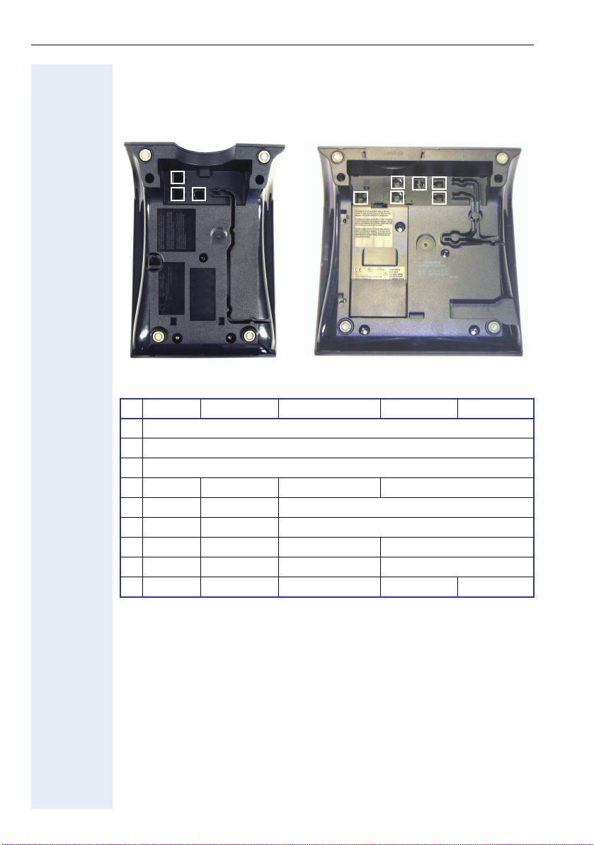
Installing the Phone
Connectors on the bottom of the telephone
1
3
2
4
3
5
1
6
2
7
optiPoint 410 entry optiPoint 410 advance
entry S economy S economy plus S standard S advance S
1 Ethernet port for LAN connection (optional with PoL*)
2 Handset connector
3 Connector for a local power supply unit (optional*)
4 - - - Module connector
5 - - Ethernet port for PC
6 - - Headset connector
7 - - - Adapter 1
8 - - - Adapter 2 9 -- - -USB-Master
* Power over LAN:
If power is supplied over the LAN cable, no local power supply is required.
8
9
20
Page 21

Installation
Starting up the optiPoint 410/420 S V7.0
The optiPoint 410/420 phone is to connect to a Switch. (The phone
is working also on a Hub, but without a guarantee of quality)
The Western plugs of all cable connections must audibly snap into
place.
• Plug the short end of the handset cable into the handset and the other
end into the connector 2 at the bottom of the telephone and feed the
cable through the guide channel in the base unit.
• Using the headset connector:
Plug the jack of the headset cable into connector 6 at the bottom of the
telephone and feed the cable through the guide channel in the base
unit.
• Using optiPoint modules (4):
Mount this device following the instructions in the installation guide
(A31003-H8400-B934-*-6ZD1).
• Using adapter (7, 8 ):
Mount this device following the instructions in the installation guide
(A31003-H8400-B934-*-6ZD1).
• Using an external keyboard:
Plug the keyboard cable into the USB connector 9 at the bottom of the
telephone.
• Using a LAN connection to PC:
Plug the jack of the connection cable into the connector 5 at the bottom
of the telephone.
Only if power not supported by LAN:
Use only the plug-in power supply unit fitting the optiPoint 410/420:
7
• Plug the jack of the LAN cable into the connector 1 at the bottom of the
• Feed the cables through the relief on the back of the housing and fix
– GER/IM: AUL:06D1284
– GBR: AUL:06D1287
– USA: AUL:51A4827
– Plug the plug-in power supply unit into the mains.
– Plug the connector 3 at the bottom of the telephone into the plug-in
power supply unit.
telephone and connect the cable with LAN.
them by means of the cable clip.
21
Page 22

Installation
Mini Switch
The default operation for the mini switch will be to auto negotiate transfer
rate (10/100 Mb/s) and duplex method (full or half duplex) with whatever
equipment is connected to the mini switch.
The software provides options to prevent auto negotiation and specify the
required transfer rate and duplex mode for the LAN and PC ports
Æ page 194.
In the default configuration for the mini switch the LAN port supports automatic detection of cable configuration (pass through or crossover cable)
and will reconfigure itself as needed to connect to the network. However
if the phone is set up to manfully configure the switch port settings then
the cable detection mechanism is disabled, in this case care must be taken
to use the correct cable type.
Depending on what has been implemented in the software IEEE802.1x
(Port based network access control) packets generated by equipment connected to the PC port will be passed through the mini switch and out of
the LAN port.
Removing the power from the phone, or a phone reset/reboot will result in
the temporary loss of the network connection to the PC port. In the case
of a reset/reboot this is about 5 seconds.
The Line Monitor diagnostic routine provides information on the configuration of the mini switch Æ page 198.
Power over LAN information
Power over LAN support is provided on the LAN port and complies with
the IEEE802.3af standard. 8 wire Ethernet cables are required to use it.
22
Page 23
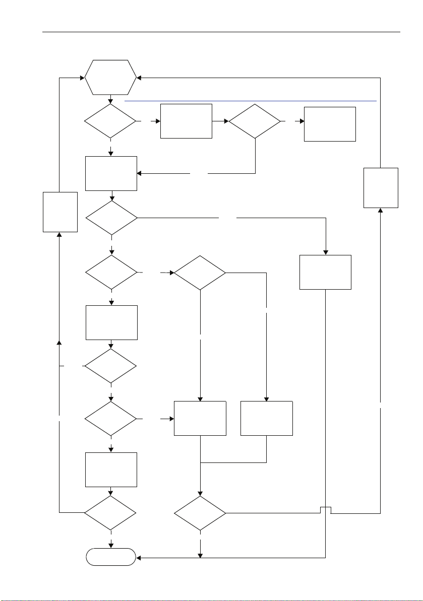
Startup Procedure
Start
Power on
Reboot
see http://wiki.siemens-enterprise.com/index.php/Setup_optiPoint_410/420_phones_with_NetBoot
Installation
Hochlauf
und
120 s
warten
No
No
No
Key 3
pressed?
No
Application
startet
DHCP
activated?
Yes
VLAN
Discovery and
L2 activated?
Yes
DHCP Discover
in untagged LAN
DHCP
successful?
Yes
VLAN ID
in Option 43?
Yes
No
No
Netboot request
L2 activated?
DHCP Discover
in untagged LAN
No
No
No
Successful?
DHCP Discover
in tagged LAN
Yes
Netboot Upgrade
Hochlauf
und
120 s
warten
Using manual
attitudes
Yes
No
Yes
DHCP Discover
in VLAN
Successful?
Yes
Registration
Successful?
Yes
23
Page 24

Using the optiPoint 410/420 family S V7.0
Using the optiPoint 410/420 family SV7.0
Properties of the optiPoint 410/420 Telephone Models
This chapter gives you an overview of the optiPoint 410/420 telephone
models and their properties
Te l e p h o n e
Model
optiPoint 410
entry
optiPoint 410
economy
optiPoint 410
economy plus
optiPoint 410
standard
optiPoint 410
advance
optiPoint 420
economy
optiPoint 420
economy plus
optiPoint 420
standard
optiPoint 420
advance
4/8No2x24NoNoNoNoNo
4/8 No 2x24 Yes No Yes No No
4/8 Yes 2x24 Yes No Yes Yes No
4/15 Yes 4x24 Yes Yes Yes Yes No
5/7No2x24NoNoNoNoYes
5/7 No 2x24 Yes No Yes No Yes
5/7 Yes 2x24 Yes No Yes Yes Yes
5/13 Yes 4x24 Yes Yes Yes Yes Yes
Function keys
Connection of
Side Car Unit
Display
Lines x Characters
Headset
connection
USB-Master
Mini-Switch
e. g. PC-connection
Speakerphone mode
8 No - No No No No No
Self labeling keys
Telephone Modes
Your administrator can configure the optiPoint 410/420 economy/
economy plus/standard advance S V7.0 for use as:
• A SingleLine phone with one line.
• A MultiLine phone with up to 10 lines (in relation with the SIP server).
24
Page 25

Control panel
Example: optiPoint 420 advance
Using the optiPoint 410/420 family S V7.0
Loudspeaker for
open listening
Handset
Dialog keys for scrolling through functions
Dialog key for confirming a function
Keys for phone settings
* With automatic key labelling
Illuminated graphics
display, 4 lines of 24
characters each
Key fields –
Programmable*:
function keys
Key fields
Programmable* function keys
Dialing keypad
optiPoint self labeling
key module
Microphone for
speakerphone
–
25
Page 26

Using the optiPoint 410/420 family S V7.0
Example: optiPoint 410 entry
Speaker
for ring tones
Handset
Keys for
telephone settings
LEDs
Key field –
freely programmable
keys*
Keypad
26
Page 27

Using the optiPoint 410/420 family S V7.0
Display and Dialog Keys
The optiPoint 410/420 is provided with a four-line (advance)/two-line (econ-
omy/economy plus/standard) display. In the normal operating mode, it dis-
plays the basic menu where you make or receive telephone calls.
optiPoint 410/420 advance
4:15PM 05.03.04
1228
Username
Menu >
optiPoint 410/420 economy/economy plus/standard
4:15PM 05.03.04
1228 Username>
The basic menu shows in its first line the time and date, and the terminal
number or name in the second line. The arrow symbol ">" on the right hand
side of the last display line points to additional functions offered. The third
line of the optiPoint 410/420 advance and the right corner of the second
line of the optiPoint 410/420 economy/economy plus/standard is used for
a free programmable Name e. g. name of the user.
If you want to navigate in menus or make settings, use the three dialog
<, >, :
keys
and function key "Stop/Escape" to navigate through the
hierarchically built up menu structure. Within this structure, the third (first)
line shows the currently selected menu, the last line a menu item of that
menu.
optiPoint 410/420 advance
4:15PM 05.03.04
Time and Date
Terminal number or name
Programmable Username
Menu
Time and Date
Terminal number or name
Programmable Username
Time and Date
Aministration:
01=Netwo rk? >
Selected Menu
Menu item
optiPoint 410/420 economy/economy plus/standard
Aministration:
01=Netwo rk? >
Selected Menu
Menu item
You can put the advance in idle mode rapidly by lifting off and replacing the handset.
27
Page 28

Using the optiPoint 410/420 family S V7.0
Dialling Keypad
The dialling keypad of the advance is labeled with digits, letters and some
special characters. You can key in letters and special characters in the corresponding input mode by pressing the corresponding key as often as is
necessary until the required letter or the required special character appears
on the display.
For example, if you want to enter the letter "R", press the key "7" three
times as "R" is at the third position. For the letter "U", press the key "8"
twice.
More information about text editors see Æ page 155.
28
Page 29
Using the optiPoint 410/420 family S V7.0
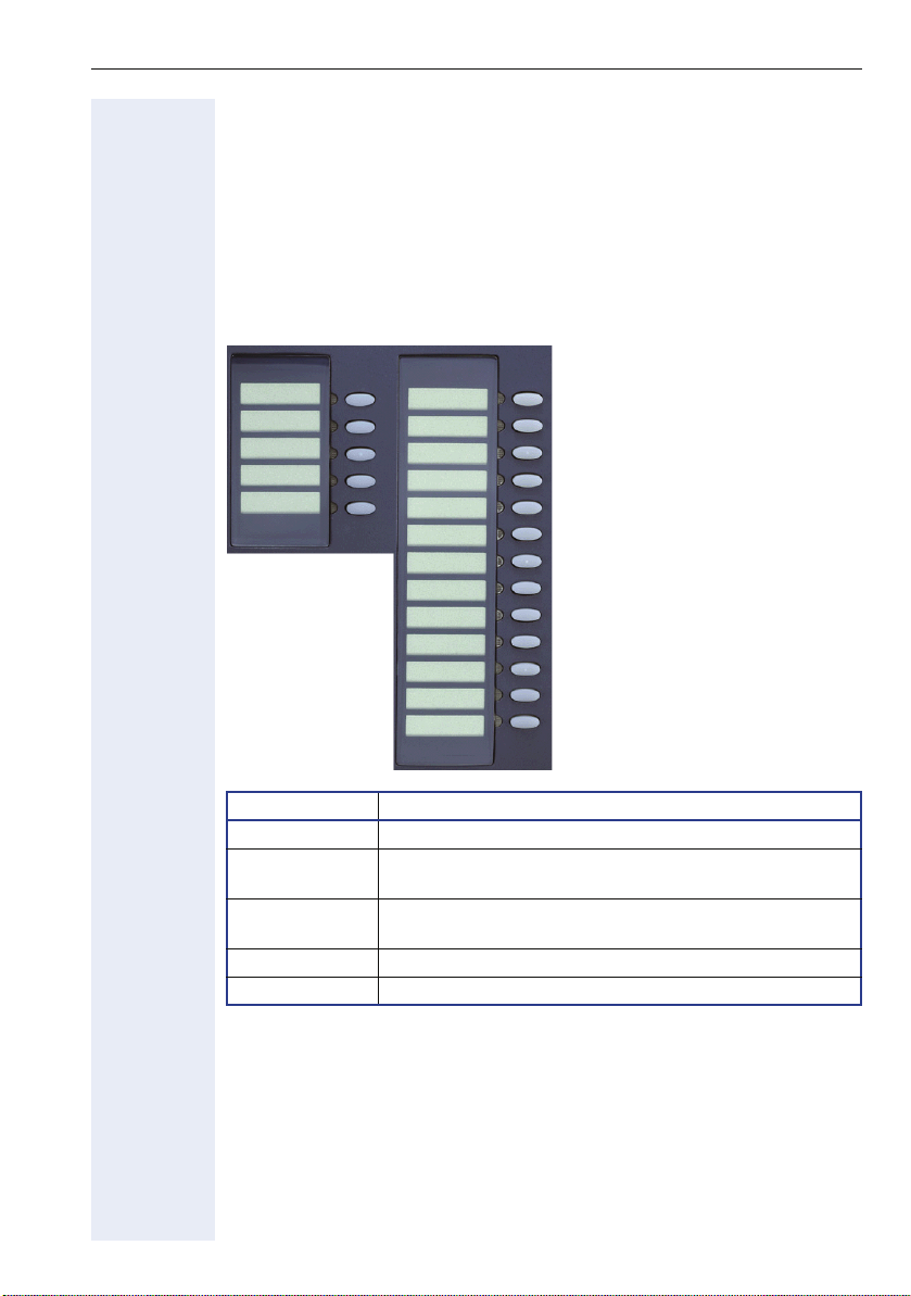
Programmable Keys
The optiPoint 410/420 family is equipped with function keys which are
user-programmable in two levels (see User Manual).
"Stop/Escape" should not be programmed. Five of these keys come already
preassigned in the first level
The types of the optiPoint 410/420 family have various numbers of function keys:
Example optiPoint 420 advance:
The function key
Loudspeaker
Repeat Dial
Missed Calls
1
2
3
4
5
6
7
8
9
10
11
12
13
14
15
16
Stop/Escape
Shift
17
18
Function Key Function
1 Switches loudspeaker of the base unit on/off
2 Shows the last 20 dialled numbers, and allows selec-
tion and redial actions
3 Shows the last 20 missed calls and allows selection,
edit and redial actions
17 Cancels the current action
18 Toggles between first and second key levels
29
Page 30

Using the optiPoint 410/420 family S V7.0
Control Keys
The two control keys v and u are located on the left side of the dialling
keypad. Depending on the operating mode, you can vary the following settings:
Operating mode
Receiving a call Reduce the volume of
Handsfree talking Reduce the volume of
Using the handset of
the telephone
Setting in the menu
"Setup" - "Audio settings"
Restart and factory
setting
v
key u key
the ringer tone
the loudspeaker in the
base unit
Reduce the volume of
the handset loudspeaker
Adjust loudspeaker volume, ringer volume, sequence and melody of the ringer tone, handset
volume and key click volume (confirmed by
Starts these functions
Increase the volume of
the ringer tone
Increase the volume of
the loudspeaker in the
base unit
Increase the volume of
the handset loudspeaker
:
)
30
Page 31

Phone Features
Phone Features
Protocol support
The economy/economy plus/standard/advance supports the following protocols:
• Æ SIP (RFC 3261 compliance)
• Æ SDP
• Æ TCP/Æ UDP
• Æ FTP
• Æ SNMP
• Æ SNTP
• Æ HTTP
• Æ RTP/Æ RTCP
• Æ DNS
• Æ DHCP
• Æ EAP (802.1X)
• Quality of service in accordance with DiffServe and IEEE 802.1p/q.
Capabilities
The advance supports the following capabilities:
Network
• Power over LAN
• DHCP for automatic IP address assignment or static IP configuration
• SNTP for automatic time synchronization
•Support for VLANs
• Support for configurable Layer 2 and 3 Quality of Service
Configuration
• Language definition (5 languages)
• Country definition allowing flexible tone generation
• Feature enable/disable
• User and administrator levels (password protected)
• Upload and download of configuration files (INI file format)
Management
• Deployment service (DLS) for configuring phones
• Web interface for configuring individual phones
• BroadSoft Centralized Management for automatic configuration
•SNMP
• Flexible phone menu system
31
Page 32

Phone Features
Speech
• Support for G711 (U and A Law), G723 and G729
• Configurable Jitter buffer support
• High Quality speaker phone functionality
• G711 Silence Suppression
• Audio codec G.722 offers a wider audio bandwidth resulting in major
improvement in the represented speech quality.
Call Features
• Call Reject
• Call deflection
• Call forwarding (Unconditional, On Busy, On no Reply)
• Call waiting
• Consultation
• Unattended Transfer
• Attended Transfer (Join)
• Local Conference (3 party, G711 only)
• Do not Disturb
•Hold
• Message Waiting
• MultiLine
• Call Park
1
32
Page 33

Phone Features
DTMF
The phone provides 2 mechanisms for transmitting Æ DTMF information,
inband and DTMF in RTP (see RFC 2833). The phone does not support outband DTMF through SIP messaging. There are no configuration parameters on the phone which control the use of DTMF.
A process of negotiation is used during call-setup to determine which form
of DTMF signaling will be used. The phone supports send DTMF information in response to the user pressing the keys 0-9 and * and # when in a
call connected state.
When a call is made from a phone it will "Offer" the remote endpoint support for DTMF in RTP (this is carried in the SDP protocol). If the far end
does not "answer" that it can support DTMF in RTP then DTMF in-band will
be used otherwise DTMF in RTP will be used.
When DTMF in RTP is negotiated the phone will always "offer" payload 100
to carry the DTMF events. The far end may accept and confirm this payload
or it may suggest a different payload value. In this case the phone will follow that payload preferred by the far end. On an incoming call the phone
will follow the payload value suggested by the far end.
The phone is not capable of retrieving or understanding DTMF in-band or
DTMF in RTP information it may receive. This information is normally used
by application or media servers to control feature access. If the user presses keys when in a call connected state and in-band DTMF has been negotiated he will hear the tones being sent in the speech path (handset only).
If DTMF in RTP has been negotiated he will here clicks as speech packets
are removed and replaced with DTMF in RTP key events.
33
Page 34

Technical Overview
Technical Overview
Session Initiation Protocol (SIP)
Overview
The Session Initiation Protocol (SIP) is a ASCII-based signalling protocol
used for establishing sessions in an IP network. A session could be a simple two-way telephone call or it could be a collaborative multi-media conference session.
Like other VoIP protocols, SIP provides signaling and session management
within a packet telephony network. Signaling allows call information to be
carried across network boundaries. Session management controls the attributes of an end-to-end call.
SIP was originally developed in the MMUSIC group within the IETF (Internet Engineering Task Force), it has been published since February 1999 as
RFC 2543. The SIP working group is continuing to enhance the protocol
and published version 2 as RFC 3261 in 2002.
SIP Functions
Systems which use SIP are able to provide the following:
• The location of the target endpoint — SIP supports address resolution,
• The media capabilities of the target endpoint—Via Session Description
• A session between the originating and target endpoint — If the call can
name mapping, and call redirection.
Protocol (SDP), SIP determines the lowest level of common services
between endpoints. Conferences are established using only the media
capabilities that can be supported by all endpoints.
be completed, SIP establishes a session between the endpoints. SIP
also supports mid-call changes such as adding another endpoint to the
conference and changing media characteristic or codec.
34
Page 35

Components in a SIP system
C
S
r
Technical Overview
SIP server
(proxy,
redirect,
registrar)
Switch
DHCP server
SNTP server
Messaging server
SNMP server
LAN
lients
PC
optiPoint 400 SIP
optiPoint 410 SIP
SIP gateway
PC
Configuration example with additional components Æ page 36
erve
FTP server
WAN
PSTN
35
Page 36

Technical Overview
SIP Components
SIP is a peer-to-peer protocol. The peers in a session are called user agents
(UAs).
SIP Clients
SIP clients include the following:
• Telephones — Act as UAS and UAC. The advance can initiate SIP re-
• Gateways — Provide call control. Gateways provide many services, the
SIP Servers
SIP servers include the following:
• Proxy servers — Receive SIP requests from a client and forward them
• Registrar servers — Process requests from UACs for registration of
Additional Components
•DHCP server
•SNTP server
• Messaging server
•SNMP server
•FTP server
• PC with internet browser
quests and respond to requests.
most common being translation between SIP conferencing endpoints
of transmission format, communications procedures, and codecs.
Other functions include call setup and clearing on both the LAN side
and the switched-circuit network side.
to the next SIP server in the network. Proxy servers can provide functions such as authentication, authorization, network access control,
routing, reliable request retransmission, and security.
their current location. Registrar servers are often colocated with redirect or proxy servers.
Distributes IP data and further information in a network automatically
(list of distributed information Æ page 175).
Provides time, date, daylight saving and timezone information.
For recording and reading messages.
Logging and maintenance of network components.
For up- and download of files from and to the phone. These include
configuration files and music files.
Enables the administration of the phone by using a Web Client such as
Internet Explorer.
36
Page 37

Technical Overview
Registration
Note that registration only occurs when the SIP Routing mode
Æ page 216 is set to "Server".
Registration is the process by which centralized SIP Server/Registrars become aware of the existence and readiness of an endpoint to make and
receive calls. The phone supports a number of configuration parameters to
allow this to happen.
Registration can be authenticated or un-authenticated depending on how
the server and phone is configured. For unauthenticated registration the
following parameters must be set on the phone:
• Terminal number Æ page 224 or Terminal name Æ page 223.
• SIP Routing Æ page 216 set to "Server".
• SIP Server/Registrar address Æ page 214 configured (IP address or
host name).
In this mode the server must pre-authenticate the user. This procedure is
server specific and is not described here.
The phone supports the Digest authentication scheme and requires the
following parameters to be configured in addition to those for unauthenticated registration:
• SIP user ID Æ page 218.
• SIP Password Æ page 215.
• SIP Realm (optional) Æ page 215.
For authentication to work the server must have created an account for the
user with matching user ID, password and Realm parameters.
Note a challenge from the server for authentication information is
not only restricted to the REGISTER message but can also occur in
response to other SIP messages eg INVITE.
Below are some specific details relating to SIP registration configuration
parameters found on the phone:
• Terminal Number Æ page 224
• Terminal Name Æ page 223
• Register by Name Æ page 210
• SIP Routing Æ page 216
• SIP Registrar (SIP Addresses) Æ page 214
• SIP Realm Æ page 215
• Registration Timer Æ page 211
If registration has not succeeded at startup or registration fails after having
been previously successfully registered the phone will try to re-register every 60 seconds. This is not configurable.
37
Page 38

Technical Overview
IP Network Protocols
DHCP
The Phone contains a Dynamic Host Configuration Protocol (DHCP) client
that supports automatic configuration of various parameters.
If DHCP is enabled in the phone, the phone will try to obtain the following
options that are essential for the configuration of its Ethernet interface automatically from a DHCP server:
• Terminal IP Address
• Terminal Mask (Network Mask)
When the telephone requests its IP address, it sends – apart from other
information – its default host name to the DHCP server. The default host
name consists of telephone model + type + MAC address (e.g.
OP410STD0001e325a845).
The available telephone models + type are listet below:
•OP410ENT
•OP410ECO
•OP410STD
•OP410ADV
• OP420ECO
• OP420STD
• OP420ADV
•OP410ECP
• OP420ECP
The DHCP server forwards this name to the DNS server, together with the
IP address assigned.
If the phone fails to configure its Ethernet interface from a DHCP server it
will eventually time-out indicating no DHCP server found and imminent restart.
Other configuration options that the phone attempts to retrieve from the
DHCP server include:
• Default Route (Routers option 3)
• IP Routing/Route 1 & 2 (Static Routes option 33)
• SNTP IP Address (NTP Server option 42)
• Timezone offset (Time Server Offset option 2)
• Primary/Secondary DNS IP Addresses (DNS Server option 6)
• DNS Domain Name (DNS Domain option 15)
• SIP Addresses / SIP Server & Registrar (SIP Server option 120)
• Vendor Unique (option 43 Æ page 39)
These parameters are not essential to basic network configuration the operation of the phone and if not obtained will not cause a reboot. The phone
assumes these parameters are not provided by DHCP until they are returned from the DHCP server. If these parameters are returned from the
DHCP server they are used and not editable in the various phone menus.
If these parameters cannot be obtained from the DHCP server the manually configured settings for these options are used.
38
Page 39

Technical Overview
SIP Server option 120:
Because the phone only reads the first name/IP address supplied in
option 120, the maximum length of the contents has been limited
to 50 octets. Please be aware of this when you are using it.
VLAN discovery per DHCP
An additional use for DHCP in the phone is the Æ VLAN discovery per
DHCP feature. This allows the phone to discover its VLAN from a DHCP
server in the untagged LAN. After discovering its VLAN the phone starts
its standard DHCP process within that discovered VLAN to configure itself
from the DHCP within that VLAN.
DHCP Support Explanation of Option 43
As no DHCP option exists for the exchange of VLAN information over
DHCP, the Vendor Specific Information option (43) shall be used to encapsulate VLAN and download configuration. The following diagram illustrates
the format of the Vendor Specific Option.
Byte # 0 1 2 3 4 5 6 7 8 9 10 11 12 13 14 15 16 17 18 19 20 21 22 23 24 25
Description
Va lu e 43 20 1 10 ’S’ ’i’ ’e’ ’m’ ’e’ ’n’ ’s ’ 0 0 0 2 4 0 0
Code
Option 1 data - "Siemens" identifier
Length
Code
Length
Option 2 data to be allocated
VID
Code
Length
Padding
Padding
0 0 0 0 0 255
VID HI
VID LO
Padding
Padding
Padding
Byte 1 contains the tag "43", option 1 data contains the "Siemens" identifier
and the VLAN ID is contained in option 2. Five Padding Bytes starting in
Byte 20 and the terminate option 255 in byte 25 complete the option
frame.
If you have to specify a configuration download server for configuration update ( see Æ page 88) so you have to add the values of the server. You can
place the new option before or after the VLAN information but the five Pad-
ding Bytes (Value 0) and the terminate option 255 have to close the op-
tion frame.
Example:
Code: 3
length: 28
data: sdlp://dls.siemens.com:18443
20 21 22 23 24 25 26 27 28 29 30 31 32 33 34 35 36 37 38 39 40 41 42 43 44 45 46 47 48 49 50 51 52 53 54 55
Option 1 data - "dls server address"
Code
Length
3 28 ’s ’ ’d’ ’l’ ’p’ ’:’ ’/’ ’/’ ’d ’ ’l’ ’s’ ’.’ ’s’ ’i’ ’e’ ’m’ ’e’ ’n’ ’s’ ’.’ ’c’ ’o’ ’m’ ’:’ ’1’ ’8’ ’4’ ’4’ ’3’00000255
Padding
Padding
Padding
Padding
Padding
Code
Code
The five Padding Bytes and the terminate option 255 now completes
the option frame in byte 48.
39
Page 40

Technical Overview
Using Vendor Classes
A "Vendor Class" is used to make sure that vendor-related information is
only sent to the telephones (instead of sending it to all other terminal devices as well). By using a vendor class, vendor information elements for
each vendor class can be sent to all devices of this vendor class. The vendor class name is either "OptiPoint" and/or "OptiIpPhone". optiPoint telephones send their vendor class name using the option 60 to the DHCP
server whenever they request data from the DHCP server.
If the option "VLAN Discovery" is set to DHCP on the telephone, the telephone registers using the vendor class name "optiPoint" during the initial
boot process, and then using the vendor class name "OptiIpPhone". On the
DHCP server, you can therefore use the vendor class name "optiPoint" to
assign the VLAN, and use the vendor class name "OptilpPhone" to assign
the DLS server address or the name. This enables a more specific configuration of the DHCP server.
The Authentication is done via digital Certificates. For detailed informationen refer to the IEEE 802.1x Configuration Management Administration Guide.
40
Page 41

Technical Overview
DNS
The phone uses Æ DNS services provided the phones operating system
to perform the following:
• Resolve the IP address of servers that have been configured as names
(DNS A,AAAA records).
• Resolve the IP address of the domain part of users called by URL (DNS
A,AAAA records).
• Identify the location of servers and provide for failover and load balancing (DNS A, AAAA and DNS SRV).
For DNS services to be used on the phone the following must be configured either manually or provided by DHCP:
• DNS Domain Name Æ page 182
• Prim DNS IP addr Æ page 207
• Sec DNS IP addr Æ page 212
If a DNS Domain Name and one or both of the DNS IP addresses
have been configured, then additionally the following host names
can be entered alternatively to the corresponding IP addresses:
• SIP addresses Æ page 214
(server, gateway, registrar)
• Download server IP address or DNS name Æ page 183
• SNMP Trap IP address or DNS name Æ page 219
• SNTP server address or DNS name Æ page 219
• Message Waiting IP address Æ page 203
•Ping Æ page 207
The Primary DNS server IP address must be configured if DNS is to be
used however the secondary server is optional. The purpose of the secondary server is to allow a backup DNS server to be used in the system
environment to increase system availability and reliability.
The phone can contact several types of server for different reasons (SNTP,
SNMP, SIP server etc). If a server has been configured by name and not IP
address the phone will provide a DNS lookup to resolve the name to an IP
address when the server needs to be contacted. To optimize network traffic performance the phone caches the result of the normal A and AAAA
record lookups and will not re-issue a request to the DNS server to resolve
that address again until the Time To Live value from the previous lookup
has expired. This mechanism does not currently apply to DNS SRV lookups.
If a secondary DNS server has been configured and the primary fails to respond to a request, that request will be re-issued to the secondary DNS
server.
41
Page 42

Technical Overview
DNS SRV
The phone supports the use of DNS SRV record lookups to allow SIP servers to be located. This mechanism is described in detail in RFC 3263 - Locating SIP Servers.
If the location to which a SIP message is to be sent is defined as a name
as opposed to an IP address a DNS SRV lookup will be performed. An example query being:
_sip._tcp.example.com.
This indicates a query for a SIP server supporting the TCP transport protocol. The transport used in this query is determined by the SIP transport
menu setting Æ page 217. The DNS server may return an IP address for
the requested SIP server or may return a single name or list of names
which require further A or AAAA record lookups to determine an IP address. The response to a DNS SRV query will also contain information regarding the Time To Live for the information returned, the port address to
which requests should be sent and weighting information relating to load
balancing of requests.
DNS SRV and failover
Lists of candidate SIP server names are often returned in response to DNS
SRV queries to allow failover mechanisms to be implemented which increase overall system availability.
If the phone sends a request to the first address in the list but fails to receive a response (currently the failover time is 6 seconds, this is not configurable) the address is placed in a "penalty box" which means that it will
not be tried again until a specific time interval has past (currently pre-set to
1 minute). The request is sent to the next SIP server in the list and the process continues. The penalty box mechanism ensures that the responsiveness of the phone is maintained by not continually retrying SIP servers that
are failing to respond.
For example the request to the first SIP server in the list fails, a call to another user hosted on the SIP server will result in the user experiencing a 6
second delay before the failover to the secondary occurs. This means the
"Calling.." status will remain on the display until the second SIP server is
contacted. All subsequent messages for this call will go to the second SIP
server until the first SIP server is removed from the penalty box and it can
be tried once again to see if it is back in service. Note this mechanism is
independent of call setup. The first SIP server will not be retried necessarily when the next call is established, only when it is removed from the penalty box.
42
Page 43

Technical Overview
SNTP
The phone support Æ SNTP. The SNTP server address can be supplied via
DHCP or manually configured Æ page 219. If the SNTP server address is
available the server will be queried for the time. If a server address is not
configured the phone will look for SNTP broadcasts and setup the time accordingly, if these are received any manually configured time and date information would be over written.
SNMP
The phone provides Æ SNMP which allows network related information to
be browsed (MIB II support). Standard SNMP browsers are sufficient for
this purpose.
43
Page 44

Technical Overview
IP Network Configuration
Routing
The phone allows a default route to be configured to allow access to Servers on a different subnet to the one in which the phone resides. In addition
it is possible to configure 2 additional routes. Each route consists of a IP
address, gateway and mask.
Virtual LAN (VLAN)
VLAN or virtual LAN is a technology that allows network administrators to
partition one physical network into a set of virtual networks (or broadcast
domains).
Physically partitioning the LAN into separate VLANs allows a network administrator to build a more robust network infrastructure. A good example
is of the data and voice networks being partitioned into data and voice
VLANs. This isolates the two networks and helps shield the endpoints
within the voice network from disturbances in the data network and vice
versa.
VLAN is a layer 2 (Physical Layer) protocol. In the case of Ethernet the
physical header is extended allowing endpoints to be not only be addressed via MAC address, but also VLAN ID Æ page 203. Ethernet VLANs
support the partitioning of a physical LAN into up to 4095 virtual LANs.
To implement a voice network based on VLANs requires the network infrastructure (the switch fabric) to support VLANs at layer 2. Dependant on the
overall architecture it may or may not be necessary for the endpoint
(phone) to support layer 2 VLAN.
The ports of the network switches in the switch fabric can be logically
grouped as ports belonging to particular VLAN. The switch only forwards
traffic to a particular port if that port is a member of the VLAN that the traffic is allocated to. In this way an endpoint connected to a particular port on
the switch is automatically a member of that VLAN without being a VLAN
aware device; the switch ensures the endpoint only receives traffic for that
VLAN and ensures traffic from the endpoint is only forwarded to ports that
are configured to be in the same VLAN. This is known as port based VLAN
in the switch world.
When multiple endpoints are connected to a single network switch port
and these endpoints belong to multiple VLANs then a different approach is
needed to implement a VLAN based topology. A typical example or this is
a phone with a PC connected behind the phone. The phone would be a
member of the Voice VLAN and the PC a member of the data VLAN. In
this case the Phone must be configured as a VLAN aware endpoint.
44
Page 45

Technical Overview
VLAN support
The phone can be configured as a Æ VLAN aware endpoint by enabling
VLAN support via the configuration menus. The following VLAN related
configurations can be achieved:
• Manually configured L2 VLAN only.
• Manually configured L2 VLAN and QoS.
• Automatically discovered VLAN and manual QoS.
To configure manual L2 VLAN only the phone must be configured at manual VLAN ID between 1 and 4095. Vlan discovery mode must be set to
manual.
To configure manual L2 VLAN and QoS the phone must be configured as
QoS layer 2 on and a manual VLAN id between 1 and 4095. Vlan discovery
mode should be set to manual and QoS layer 2 and 3 values should be configured as described in the QoS section below.
If you mis-configure a phone to an incorrect VLAN the phone will behave
as though it is not configured for and possibly not connected to the network. In DHCP mode it will behave as though the DHCP server cannot be
found, in fixed IP mode no server connections will be possible.
To automatically discover a VLAN ID using DHCP the phone must be configured as DHCP enabled and VLAN discovery mode set to DHCP. If QoS
is required this can be turned on and QoS layer 2 and 3 values should be
configured as described in the QoS section below.
The DHCP server must be configured to supply the Vendor Unique Option
in the correct Siemens VLAN over DHCP format.
If a phone configured for Vlan discovery by DHCP fails to discover its VLAN
it will proceed to configure itself from the DHCP within the non-tagged
LAN. In these circumstances network routing will probably not be correct;
the SIP server may or may not be reached. The default setting for the
phone is to try and perform VLAN discovery.
DLS
The Deployment Service (DLS) is a HiPath Management application for administering workpoints (optiPoint telephones and optiClient installations)
in HiPath 8000 networks. It has a Java-supported, web-based unser interface, which runs on an internet browser. Amongst the most important features are: security (e.g. PSS generation and distribution within an Æ SRTP
security domain), mobility for optiPoint Sip phones, software deployment,
plug&play support, as well as error and activity logging.
For detailed informationen about DLS refer to the HiPath Deployment Service Administration Manual.
The Authentication is done via digital Certificates. For detailed informationen refer to the IEEE 802.1x Configuration Management Administration Manual.
45
Page 46

Technical Overview
Quality of Service (QoS)
Modern networks can be used to provide various Qualities of Service to
network endpoints based upon the importance of the endpoint and its
generated traffic. Quality of Service is a term used to describe this catagorisation of network traffic in networks based on the importance of the data
and the treatment of that prioritized traffic.
A typical example of use of QoS in a network is that of an IP Phone. Telephone Voice traffic is more important that for HTTP related traffic for a PC.
Prioritization of voice traffic over that of the HTTP traffic means that during
periods of heavy network load that voice service is maintained, whereas
the response times for a user's Web Broweser will degrade and possibly
stop working.
Quality of Service can be supported in networks at both Layer 2 and Layer
3. At Ethernet layer 2 the MAC header is extended to provide VLAN information and Quality of Service priorities. Ethernet layer 2 allows for prioritisation of traffic from 0 (lowest) to 7 (highest). At the layer 3, the IP layer
traffic can be prioritized using information embedded in the IP Type of service (DiffServ) field that allows for 64 levels of prioritization.
To utilize Quality of Service features the network infrastructure (switch fabric) must support prioritized delivery of traffic based on layer 3 and/or layer
2.
Secure Payload
optiPoint 410/420 advance S V7.0 telephones enable you to establish a secure telephone connection, provided that the recipient’s telephone is also
capable of this. Voice transmission is encrypted and subsequently decrypted by the called party’s telephone and vice versa. Even the signaling for the
call-setup and the exchange of the encryption data is carried out via a secure connection. The telephones have to have a valid registration at an SIP
server via.
46
Page 47

Administration Interfaces
Administration Interfaces
You can configure the optiPoint 410/420 by using any of the following
methods.
Phone Menu
For direct configuration of an optiPoint 410/420 entry economy/
economy plus/standard/advance S V7.0. Access to the phone is required.
The dialling-keypad, the two-line display and the handset of the phone supports you in72
configuring the optiPoint 410/420.
Menu overview see Æ page 148.
As long as the IP connection is not properly configured, you have
to use this methode to setup the phone.
Web Interface
For remote configuration of individual IP phones in your network. Direct access to the phone is not required.
Menu overview see Æ page 110.
To use this method, the phone must first obtain IP connectivity.
The remote configuration is not applicable while the phone is not
in idle mode.
47
Page 48

Basic Administration
Basic Administration
The phone is factory preconfigured to allow for a minimum of configuration
activites required on the unit itself. A number of parameters can be configured centrally by using a DHCP server. When the phone is connected to
the network it will react as follows:
• If your network use a DHCP server, the telephone will try to get its IP
• If the DHCP server is not available or configured to provide these pa-
Access to the Phone Administrator and Diagnostics Menu
Administrator menu
The following steps describe the access to the optiPoint 410/
420 economy/economy plus/standard/advance administration menu,
starting from idle state.
1. Select the menu „05=Setup“ by pressing the key
2. Select the administrator menu by pressing the key
Address, IP Address Mask, SIP Addresses (server, gateway, registrar),
SNTP Server Address Configuration Download Server Address and
Time Offset from the DHCP server (completely list see Æ page 38).
In this case the telephone will boot with the IP address and will get the
exact time from the configured SNTP server.
You only have to configure the Terminal number, SIP user ID and password and the language Æ page 50.
rameters, the telephone will become idle and has to be manually configured Æ page 51.
> several times.
Menu:
05=Setup? >
Confirm with the key
:.
j.
Enter admin password
3. Enter the administrator password (default: „123456“).
The entry is masked by asterisks „*“.
Enter admin password
******
Confirm with the key
4. Now the first menu item in the administrator menu is shown:
Administration
01=N etwork>
You can change the sub-menu by pressing the keys < > or you can
open the menu „01=Network“ by pressing the key
48
:.
:.
Page 49

Basic Administration
Diagnostics menu
The following steps describe the access to the optiPoint 410/
420 economy/economy plus/standard/advance diagnostics menu, starting
from idle state.
1. Select the menu „05=Setup“ by pressing the key
Menu:
05=Setup? >
Confirm with the key
2. Select the diagnostics menu by pressing the key
Enter admin password
3. Enter the administrator password (default: „123456“).
The entry is masked by asterisks „*“.
Enter admin password
******
Confirm with the key
4. Now the first menu item in the dignostics menu is shown:
Diagnostics
01=Display test?>
:.
:.
> several times.
k.
You can change the sub-menu by pressing the keys
open the menu „01=Display test“ by pressing the key
< > or you can
:.
49
Page 50

Basic Administration
Basic Configuration
optiPoint 410/420 economy/economy plus/standard/advance
Configuration using DHCP Server
The optiPoint 410/420 is factory-configured to have an IP address automatically assigned to it by the DHCP server as soon as it’s connected to LAN.
If your network use a DHCP server, the telephone will try to get its IP Address, IP Address Mask, SIP Addresses (server, gateway, registrar), SNTP
Server Address Configuration Download Server Address and Time Offset
from the DHCP server (completely list see Æ page 38).
In this case the following parameters have to be configured:
Parameter
Te r m in a l
Number
SIP User ID
SIP Password
Language
The Authentication is done via digital Certificates. For detailed informationen refer to the IEEE 802.1x Configuration Management Administration Manual.
Æ page 224
Æ page 218
Æ page 215
Phone path
(Menu Æ page 148)
- 02=System
- 01=Terminal Number
(change terminal number)
- 02=System
- 10=SIP User Id
(change ID)
- 02=System
- 11=SIP Password
(change password)
Y
- 2=Configuration
- 02=Language
(select language)
Web Interface path
(Menu Æ page 110)
- SIP environment
- Terminal number
(enter terminal number)
- SIP environment
- SIP user ID
(enter ID)
- SIP environment
- New/Confirm SIP password
(enter/re-enter password)
(WBM user interface)
50
Page 51

Basic Administration
Manual Configuration
If your network does not use a DHCP server, you must disable the DHCP
IP assignment manually and specify the phone’s IP address and subnet
mask and the network gateway IP address (default route) for the phone.
In this case the following parameters have to be configured:
Parameter
DHCP
IP Assignment
Æ page 175
Te r m in a l
IP Address
Æ page 223
Te r m i n a l M as k
Æ page 223
Default Route
Æ page 174
1 as long as no IP connection exists
Phone path
(Menu Æ page 148)
- 01=Network
- 01=DHCP IP assign
(switch off)
- 01=Network
- 02=Terminal IP addr.
(change IP address)
- 01=Network
- 03=Terminal mask
(change terminal mask)
- 01=Network
- 04=Default route
(change default route)
Web Interface path
(Menu Æ page 110)
(not applicable
(not applicable
(not applicable
(not applicable
1
)
*
)
*
)
*
)
If you want to use the Web Interface for further administration (phone configuration by PC) you have to reboot the phone now.
51
Page 52

Basic Administration
After reboot
After reboot the following parameters have to be configured:
Parameter
Te r m in a l
Number
SIP User ID
SIP Password
SIP Server
Address
SIP Registrar
Address
SIP Routing
Language
1 or host name (if DNS is applicable Æ page 41)
Æ page 224
Æ page 218
Æ page 215
Æ page 214
Æ page 214
Æ page 216
Phone path
(Menu Æ page 148)
- 02=System
- 01=Terminal Number
(change terminal number)
- 02=System
- 10=SIP User Id
(change ID)
- 02=System
- 11=SIP Password
(change password)
- 02=System
- 07=SIP Addresses
- 1=SIP Server
(change IP address
- 02=System
- 07=SIP Addresses
- 2=SIP Registrar
(change IP address
- 02=System
- 04=SIP Routing
(select routing)
1
)
*
)
Y
- 2=Configuration
- 02=Language
(select language)
Web Interface path
(Menu Æ page 110)
- SIP environment
- Terminal number
(enter terminal number)
- SIP environment
- SIP user ID
(enter ID)
- SIP environment
- New/Confirm SIP password
(enter/re-enter password)
- SIP environment
- Server IP address
(enter IP address
- SIP environment
- Registrar IP address
(enter IP address
- SIP environment
- SIP routing
(select routing)
(not applicable)
*
)
*
)
52
Page 53

Step by Step
Basic Administration
optiPoint 410 entry
Configuration using DHCP Server
The optiPoint 410/420 is factory-configured to have an
IP address automatically assigned to it by the DHCP
server as soon as it’s connected to LAN.
The Authentication is done via digital Certificates.
For detailed informationen refer to the IEEE
802.1x Configuration Management Administration Manual.
If your network use a DHCP server, the telephone will
try to get its IP Address, IP Address Mask, SIP Addresses (server, gateway, registrar), SNTP Server Address
Configuration Download Server Address and Time Offset from the DHCP server (completely list see
Æ page 38).
In this case the following parameters have to be configured using the Web Interface Administrator Menu.
Parameter
Te r mi n a l N um be r
Æ page 224
SIP User ID
Æ page 218
SIP Password
Æ page 215
Language WBM user interface
Web Interface path
(Menu Æ page 110)
- SIP environment
- Terminal number
(enter terminal number)
- SIP environment
- SIP user ID
(enter ID)
- SIP environment
- New/Confirm SIP password
(enter/re-enter password)
53
Page 54

Basic Administration
Step by Step
<PROG>
<VIEW>
Manual Configuration
If your network does not use a DHCP server, you must
disable the DHCP IP assignment manually and specify
the phone’s IP address and subnet mask and the network gateway IP address (default route) for the phone.
Entering the administration area
e d g Press the keys simultaneously
or
v u q j Press the keys successively.
o Enter admin password
(default: 123456).
r Terminate the operation.
You are now in the Administration Area (all LEDs
flash).
The top two function keys take over the following functions in this area:
st
1
Function key
st
Press 1
2nd Function key
Press 2
codes see Æ Seite 160)
function key to make settings.
nd
function key to view settings. (ASCII results
Configure basics
<PROG>
Press 1
st
function key.
dd Enter code
d Switch the DHCP IP assign off.
r Terminate the operation.
<PROG>
Press 1st function key.
de Enter code.
o Enter IP address of the optiPoint 410 entry
(to edit see Æ Seite 160).
r Terminate the operation.
<PROG>
54
Press 1st function key.
Page 55

Step by Step
Basic Administration
<PROG>
<PROG>
<PROG>
df
Enter code.
o Enter terminal mask of the optiPoint 410 entry
(to edit Æ Seite 160).
r Terminate the operation.
Press 1st function key.
dg Enter code.
o Enter the default Route of the optiPoint 410 entry
(to edit see Æ Seite 160).
r Terminate the operation.
Only if you are working in a Virtual LAN (VLAN):
Press 1st function key.
fid Input the code to define the manual configuration of
the VLAN Discovery Mode.
r Terminate the operation.
Press 1st function key.
fh Enter code.
o Enter (0 - 4095) for the Virtual LAN ID.
r Terminate the operation.
<PROG>
Confirm your entries and start the telephone:
Press key.
mm Enter the code.
r Confirm the entry.
After the start, the telephone is silent and you can make
the other settings.
Other settings
All other settings of your optiPoint 410 entry must be
made through the "Web-based Management Tool"
Æ page 109.
55
Page 56

Basic Administration
After reboot the following parameters have to be configured:
Parameter
Te r mi na l N um be r
SIP User ID
SIP Password
SIP Server Address
SIP Registrar Address
SIP Routing
Æ page 224
Æ page 218
Æ page 215
Æ page 214
Æ page 214
Æ page 216
Web Interface path
(Menu Æ page 110)
- SIP environment
- Terminal number
(enter terminal number)
- SIP environment
- SIP user ID
(enter ID)
- SIP environment
- New/Confirm SIP password
(enter/re-enter password)
- SIP environment
- Server IP address
(enter IP address
- SIP environment
- Registrar IP address
(enter IP address
- SIP environment
- SIP routing
(select routing)
*
)
*
)
56
Page 57

Extended Administration
Extended Administration
Configure Network Parameters
To access a SIP server as an IP client some network related information
have to be configured.
Depending on the SIP network environment different changes are
necessary Æ page 48.
Network Addresses
Parameter
DHCP
IP Assignment
Æ page 175
Te r m in a l
IP Address
Æ page 223
Te r m i n a l M as k
Æ page 223
Default Route
(Gateway)
Æ page 174
IP Route 1/2
(IP address/
Gateway/Mask)
Æ page 191
DNS Domain
Name
Æ page 182
Phone path
(Menu Æ page 148)
- 01=Network
- 01=DHCP IP assign
(switch on/off)
- 01=Network
- 02=Terminal IP addr.
(change IP address)
- 01=Network
- 03=Terminal mask
(change terminal mask)
- 01=Network
- 04=Default route
(change default route)
- 01=Network
- 05=IP routing
- 1=Route 1 or
- 2=Route 2
- 1=IP address 1/2
(change IP address)
- 2=Gateway 1/2
(change IP address)
- 3=Mask 1/2
(change subnet mask)
- 01=Network
- 07=DNS Domain name
(change domain name)
Web Interface path
(Menu Æ page 110)
- Network IP and routing
- DHCP
(activate/deactivate checkbox)
- Network IP and routing
- Terminal IP address
(enter IP address)
- Network IP and routing
- Terminal mask
(enter terminal mask)
- Network IP and routing
- Default gateway
(enter gateway address)
- Network IP and routing
- IP routing (Route 1/2)
- Route
(enter IP address)
- Gateway
(enter IP address)
- Mask
(enter subnet mask)
- Network IP and routing
- Domain name
(enter domain name)
57
Page 58

Extended Administration
Parameter
Primary DNS IP
Address
Æ page 207
Secondary DNS
IP Address
Æ page 212
User specific
web ad - 01=Network
Te r m in a l
hostname
Æ page 221
Use dynamic
hostname
Æ page 227
Phone path
(Menu Æ page 148)
- 01=Network
- 08=Prim DNS IP addr
(change IP address)
- 01=Network
- 09=Sec DNS IP addr
(change IP address)
- 12=User specific web ad
(switch on/off)
- 01=Network
- 13=Terminal Hostname
(change name)
- 01=Network
- 14=Use dynamic hostname
(mark to enable/disable))
Web Interface path
(Menu Æ page 110)
- Network IP and routing
- Primary DNS IP address
(enter IP address)
- Network IP and routing
- Secondary DNS IP address
(enter IP address)
(not applicable)
- Network IP and routing
- Terminal hostname
(change name)
- Network IP and routing
- Use dynamic hostname concept
(mark to enable/disable))
Changing either the DHCP IP assignment or the Terminal IP address
will take effect as soon as the optiPoint 410/420 is restarted.
Quality of Service (QoS)
By changing the Quality of Service parameter you can affect the speech
quality results. Further speech quality parameters see Æ page 93.
QoS Configuration
Parameter
QoS Mode
Æ page 208
Layer 3 Voice
(only if L3On)
Æ page 193
Phone path
(Menu Æ page 148)
- 01=Network
- 06=QoS
- 2=QoS L2/L3
- 1=L2Off/L3Off or
- 2=L2Off/L3On or
- 3=L2On/L3On
- 01=Network
- 06=QoS
- 3=L3 Voice
(select value)
Web Interface path
(Menu Æ page 110)
- Quality of Service
- Required
(select QoS mode)
- Quality of Service
- Layer 3 Voice
(select Layer 3 Voice value)
58
Page 59

Extended Administration
Parameter
Layer 3
Signalling
(only if L3On)
Æ page 193
Layer 2 Voice
(only if L2On)
Æ page 194
Layer 2
Signalling
(only if L2On)
Æ page 193
Layer 2 Default
(only if L2On)
Æ page 193
Phone path
(Menu Æ page 148)
- 01=Network
- 06=QoS
- 4=L3 Signalling
(select value)
- 01=Network
- 06=QoS
- 5=L2 Voice
(enter Value)
- 01=Network
- 06=QoS
- 6=L2 Signalling
(enter Vaulue)
- 01=Network
- 06=QoS
- 7=L2 Default
Web Interface path
(Menu Æ page 110)
- Quality of Service
- Layer 3 Signalling
(select Layer 3 Signalling value)
- Quality of Service
- Layer 2 Voice
(enter Layer 2 Voice value)
- Quality of Service
- Layer 2 Signalling
(enter Layer 2 Signalling value)
- Quality of Service
- Default
(enter Default value)
Changing any QoS settings will take effect as soon as the
optiPoint 410/420 is restarted.
VLAN Settings
Parameter
Manual VLAN
Identifier
Æ page 203
VLAN Discovery
Method
Æ page 228
Phone path
(Menu Æ page 148)
- 01=Network
- 06=QoS
- 8=VLan ID
(enter VLAN ID)
- 01=Network
- 06=QoS
- 9=VLAN discovery
(select VLAN discovery)
Web Interface path
(Menu Æ page 110)
- Quality of Service
- Manual vLAN identifier
(enter VLAN ID)
- Quality of Service
- vLAN discovery method
(select VLAN discovery)
Changing the VLAN Discovery Method will take effect as soon as
the optiPoint 410/420 is restarted.
59
Page 60

Extended Administration
Configure LAN Ports
Parameter
LAN/PC Port
Setting
Æ page 194
Phone path
(Menu Æ page 148)
- 01=Network
- 10=LAN port settings or
- 11=PC port settings
(select port setting)
Web Interface path
(Menu Æ page 110)
- LAN port settings
- LAN port 1 (LAN) or
- LAN port 2 (PC)
(select port setting)
Changing any LAN port setting will cause the optiPoint 410/420 to
restart.
60
Page 61

Extended Administration
Configure System Information
To be granted access to a SIP Server some terminal and SIP related information have to be configured.
First of this the SIP server has to be configured.
Terminal Details
Parameter
Te r m in a l
Number
Æ page 224
Te r m i n a l N am e
Æ page 223
Register by
Name
Æ page 210
User Display ID
Æ page 182
Use Display ID
Æ page 182
Phone path
(Menu Æ page 148)
- 02=System
- 01=Terminal Number
(change terminal number)
- 02=System
- 02=Terminal Name
(change terminal name)
- 02=System
- 03=Register by Name
(switch on/off)
- 02=System
- 44=Display ID
- 1=New/Change ID
(enter display name)
- 02=System
- 44=Display ID
- 2=Use Terminal ID
- 3=Use Display ID
(enable/disable)
Web Interface path
(Menu Æ page 110)
- SIP environment
- Phone number
(enter terminal number)
- SIP environment
- Phone name
(enter terminal name)
- SIP environment
- Register by name
(activate/deactivate checkbox)
- SIP environment
- Display ID
(enter display name)
- SIP environment
- Use Display ID
(enable/disable)
61
Page 62

Extended Administration
SIP Specific Configuration
Parameter
SIP Routing
Æ page 216
Outbound
Proxy
Æ page 205
Default OBP
Domain Name
Æ page 174
SIP Server
Address
Æ page 214
SIP Registrar
Address
Æ page 214
SIP Gateway
Address
Æ page 214
SIP Phone Port
Æ page 214
SIP Transport
Æ page 217
Phone path
(Menu Æ page 148)
- 02=System
- 04=SIP Routing
(select routing)
- 02=System
- 05=Outbound Proxy
(switch on/off)
- 02=System
- 06=Default OBP Domain
(change domain name)
- 02=System
- 07=SIP Addresses
- 1=SIP Server
(change IP address
port)
- 02=System
- 07=SIP Addresses
- 2=SIP Registrar
(change IP address
port)
- 02=System
- 07=SIP Addresses
- 3=SIP Gateway
- 1=SIP Register Address
- 2=SIP Gateway Port
(change IP address
port)
- 02=System
- 07=SIP Addresses
- 5=SIP Phone
- 1=SIP Port
- 2=RTP Base Port
(change port address)
- 02=System
- 08=SIP Transport
- 1=UDP
- 2=TCP
(select transport)
1
and
*
and
*
and
Web Interface path
(Menu Æ page 110)
- SIP environment
- SIP routing
(select routing)
- SIP environment
- Outbound Proxy
(activate/deactivate checkbox)
- SIP environment
- Default domain name
(enter domain name)
- SIP environment
- Server IP address or DNS name
(enter IP address
- SIP environment
- Registrar IP address or DNS
name
(enter IP address
- SIP environment
- Gateway IP address or DNS
name
(enter IP address
- SIP environment
- SIP Port
- RTP Base Port
(enter Port addresses)
- SIP environment
- SIP transport
(select transport)
*
)
*
)
*
)
62
Page 63

Extended Administration
Parameter
SIP server type
Æ page 216
SIP Realm
Æ page 215
SIP User ID
Æ page 218
SIP Password
Æ page 215
SIP Session
Timer
Æ page 217
SIP Session
Time
Æ page 216
Registration
Timer
Æ page 211
Tr a n s a c t i o n
timer
Æ page 225
1 or host name (if DNS is applicable Æ page 41)
Phone path
(Menu Æ page 148)
- 02=System
- 31=SIP Server type
(select type)
- 1=HiQ/HiPath 8000
- 2=Broadsoft
- 3=Sylantro
- 4=Other
- 02=System
- 09=SIP Realm
(change realm name)
- 02=System
- 10=SIP User Id
(change ID)
- 02=System
- 11=SIP Password
(change password)
- 02=System
- 12=SIP Session Timer
(switch on/off)
- 02=System
- 13=SIP Session Time
(enter time)
- 02=System
- 17=Registration Timer
(enter time)
- 02=System
- 46=Transaction timer
(enter time)
Web Interface path
(Menu Æ page 110)
- SIP environment
- SIP server type
(select type)
- SIP environment
- SIP realm
(enter realm name)
- SIP environment
- SIP user ID
(enter ID)
- SIP environment
- New/Confirm SIP password
(enter/re-enter password)
- SIP environment
- SIP session timer enabled
(activate/deactivate checkbox)
- SIP environment
- SIP session timer value
(enter time)
- SIP environment
- Registration timer value
(enter time)
- SIP environment
- Transaction Timer
(enter time)
Changing either the Terminal Number or the SIP Routing setting will
take effect as soon as the optiPoint 410/420 is restarted.
63
Page 64

Extended Administration
SIP Features
Parameter Phone path
(Menu Æ page 148)
Web Interface path
(Menu Æ page 110)
Call handling options
Auto answer
Æ page 214
Beep on Auto answer
Æ page 215
Auto recon nect
Æ page 215
Beep on Auto
reconnect
Æ page 215
Allow Refuse
Æ page 164
Y
- 2=Configuration
- 32=Auto answer
(mark to be enabled)
Y
- 2=Configuration
- 33=Autoanswer beep
(mark to be enabled)
Y
- 2=Configuration
- 34=Auto reconnect
(mark to be enabled)
Y
- 2=Configuration
- 35=Autoreconnect beep
(mark to be enabled)
- 02=System
- 32=Allow Refuse
(enable or disable)
- SIP features
- Auto answer
(mark to be enabled)
- SIP features
- Beep on Auto answerI
(mark to be enabled)
- SIP features
- Auto reconnect
(mark to be enabled)
- SIP features
- Beep on Auto reconnect
(mark to be enabled)
- SIP features
- Refuse call feature enabled
(mark to be enabled)
Group pickup
Group pickup
URI
Æ page 189
- 02=System
- 30=Group pickup URI
(enter Group picup URI)
- SIP features
- Group pickup URI
(enter URI)
HotWarm Phone
Phone type
Æ page 190
Default dial
string
Æ page 190
- 02=System
- 33=Hot/Warm Phone
- 1=Normal line Action
- 2=Warm line
- 3=Hot line
(select type)
and default dial string
- SIP features
- Phone typeI
(select type)
- Default dial string
(enter dial string)
Centralized-controlled conference ( only with Sylantro Servers)
Conference
factory URI
Æ page 170
- 02=System
- 27=Conf Server Addr.
(enter URI)
- SIP features
- Conference factory URI
(enter address)
64
Page 65

Extended Administration
Parameter Phone path
(Menu Æ page 148)
Web Interface path
(Menu Æ page 110)
Call park (only with Sylantro Servers)
Call park URI
Æ page 169
Call pickup URI
Æ page 169
Tr a n s f e r on
Ringing
Æ page 226
Join allowed in
conference
Æ page 192
Callback URIs
Æ page 169
Initial Digit
Timer
Æ page 191
Call Recorder
Æ page 168
Tr a n s f e r on
hangup
Æ page 226
1 For future use – not supported with HiPath 8000
- 02=System
- 38=Call Park URI
(enter URI)
- 02=System
- 39=Call Park Pickup URI
(enter URI)
- 02=System
- 40=Transfer on Ringing
(enable or disable)
- 02=System
- 41=Join allowed in conf
(enable or disable)
- 02=System
- 42=Callback URIs
- 1=Callback-busy
- 2=Callback-no reply
- 3=Cancel callbacks
select and enter access code
- 02=System
- 43=Initial Digit Timer
(set timer 1 to 120)
- 02=System
- 45=Call recorder
- 1=Dial string
- 2=Audible indication
(enter string and set indication to on/off)
- 02=System
- 48=Transfer on hangup
(switch on/off)
- SIP features
- Call park URI
(enter URI)
- SIP features
- Call pickup URI
(enter URI)
- SIP features
- Allow transfer on ringing
(mark to allow)
- SIP features
- Allow join in conference
(mark to allow)
- SIP features
- Callback
(enter related access code)
1
- SIP features
- Initial digit timer
(set timer 1 to 120)
- SIP features
- Call Recorder
- Number
- Audible indication
(enter number and mark indication as on)
- SIP features
- Allow transfer on hangup
(mark to enable)
65
Page 66

Extended Administration
Miscellaneous
Parameter
Emergency
Number
Æ page 185
Voicemail
Number
Æ page 228
Message
Waiting Address
Æ page 203
Banding
Identity name
Æ page 168
1 or host name (if DNS is applicable Æ page 41)
Phone path
(Menu Æ page 148)
- 02=System
- 14=Emergency No.
(change emergency number)
- 02=System
- 15=Voice mail No.
(change voicemail number)
- 02=System
- 16=MWI Server Addr.
(change IP address
- 02=System
- 26=System Name
(change description)
1
)
Web Interface path
(Menu Æ page 110)
- SIP environment
- Emergency number
(enter emergency number)
- SIP environment
- Voicemail number
(enter voicemail number)
- SIP environment
- Message Waiting IP Address or
DNS name
(enter IP address
- SIP environment
- Banding/Identity name
(enter short description)
*
)
66
Page 67

Extended Administration
Configuring Date and Time
If the DHCP server in your network provides information about the SNTP
server access, the date and time is automatically shown on the phone.
If the DHCP server in your network does not provide a SNTP address you
have to set the SNTP address manually.
If no SNTP server is in your network you have to configure the date and
time manually.
If SNTP is being used, any user specified value for Time and Date
will be overwritten when the next SNTP update occurs!
SNTP is available, but no automatic access by DHCP server
Parameter
SNTP Address
Æ page 219
Timezone Offset
Æ page 225
1 or host name (if DNS is applicable Æ page 41)
Phone path
(Menu Æ page 148)
- 04=Date/Time
- 1=SNTP IP addr
(change IP address
- 04=Date/Time
- 2=Timezone offset
(change timezone offset)
1
)
No SNTP server available
Parameter
Date/Time
Æ page 173
Daylight Saving
Time
Æ page 174
Phone path
(Menu Æ page 148)
Y
- 2=Configuration
- 03=Date/time
(select a date format and
change date and time)
Y
- 2=Configuration
- 14=Daylight Saving
(switch on/off)
Web Interface path
(Menu Æ page 110)
- Time and date
- SNTP server IP address or DNS
name
(enter IP address
- Time and date
- Time zone offset
(enter timezone offset)
*
)
Web Interface path
(Menu Æ page 110)
- Time and date
- Local time/Date
(enter Local time, enter/select
Date)
- Time and date
- Daylight saving
(activate/deactivate checkbox)
67
Page 68

Extended Administration
Multiline
Line key configuration
In line overview menu you can configure lines and an assign lines to keys.
It suffices to assign one line to a key for to go in multiline operation.
Parameter
Line
Æ page 196
Key Label
Æ page 192
Address of
record
Æ page 199
Realm
Æ page 201
Primary line
Æ page 201
Ring
Æ page 201
Phone path
(Menu Æ page 148)
(not applicable) - Funcktion keys
(not applicable) Line key configuration dialog
(not applicable) Line key configuration dialog
(not applicable) Line key configuration dialog
(not applicable) Line key configuration dialog
- 02=System
- 28=Keyset
- 01=Line
select a line
- 2=Ringer setting
(Read only)
Web Interface path
(Menu Æ page 110)
- Phone
or
- Key module
- Select a key with EDIT
a configuration dialog appears
- Select:line
(A key with line is ready for con-
figuring)
- Key Label
(enter a name for the line key –
only with optiPoint 420)
- Address of record
(enter e.g. phone number)
- Realm
(enter IP address)
- Primary line
(mark as primary if required)
Line key configuration dialog
- Ring
(enable/disable)
68
Page 69

Extended Administration
Parameter
Hunt ranking
Æ page 199
User ID
Æ page 201
Password
Æ page 200
Shared type
Æ page 200
Phone path
(Menu Æ page 148)
- 02=System
- 28=Keyset
- 1=Line
select a line
- 1=Rank
(enter Rank 1 to 10)
(not applicable) Line key configuration dialog
(not applicable) Line key configuration dialog
(not applicable) - Line key configuration dialog
Configure Multiline Operation
Parameter
Registration
LEDs
Æ page 210
Rollover type
Æ page 212
Rollover Volume
Æ page 212
Originating line
preference
Æ page 204
Phone path
(Menu Æ page 148)
- 02=System
- 28=Keyset
- 2=Registration LEDs
(switch on/off)
- 02=System
- 28=Keyset
- 03=Rollover type
(select rollover type)
- 02=System
- 28=Keyset
- 04=Rollover Vol
(change volume)
- 02=System
- 28=Keyset
- 05=Orig line pref
(select line preference)
Web Interface path
(Menu Æ page 110)
Line key configuration dialog
- Hunt ranking
(select order)
- User ID
(enter ID)
- Password
(enter password)
- Shared type
(select type)
Web Interface path
(Menu Æ page 110)
- Multiline operation
- Registration LEDs
(activate/deactivate checkbox)
- Multiline operation
- Rollover type
(select rollover type)
(not applicable)
- Multiline operation
- Originating line preference
(select line preference)
69
Page 70

Extended Administration
Parameter
Terminating line
preference
Æ page 224
Line action
mode
Æ page 197
Show focus
Æ page 213
Forwarding
Indication
Æ page 186
Reservation
Timer
Æ page 211
Phone path
(Menu Æ page 148)
- 02=System
- 28=Keyset
- 06=Term line pref
(select line preference)
- 02=System
- 28=Keyset
- 07=Line action mode
(select line action mode)
- 02=System
- 28=Keyset
- 09=Show focus
(switch on or off)
- 02=System
- 28=Keyset
- 10=Forwarding Ind
(switch on or off)
- 02=System
- 28=Keyset
- 11=Reservation Timer
(set time)
Web Interface path
(Menu Æ page 110)
- Multiline operation
- Terminating line preference
(select line preference)
- Multiline operation
- Line key operation mode
(select operation mode)
- Multiline operation
- Show focus
(mark to enable)
- Multiline operation
- Use LED to indicate Remote
Forwarding
(mark to enable)
- Multiline operation
- Reservation timer
(set time)
Dial Plan Configuration and Status
Parameter
Dial Plan
Æ page 176
Dial Plan Info
Æ page 176
Phone path
(Menu Æ page 148)
- 02=System
- 29=Dial Plan
(enable/disable)
- 07=General info
- 4=Dial Plan
- 1=ID
- 2=Stauts
70
Web Interface path
(Menu Æ page 110)
- System
- Dial Plan
- Action
(enable/disable)
- General information
- Dial plan
- Name and Status
Page 71

Extended Administration
Dialling Properties
Only used with optiPoint 410/420 advance/standard
Parameter
Dialling
properties
Æ page 181
Phone path
(Menu Æ page 148)
- 02=System
- 35=LDAP
Select one of the options for
to change its value
- 3=External code
- 4=International prefix
- 5=Country code
- 6=National prefix
- 7=Area code
- 8=District code
Web Interface path
(Menu Æ page 110)
- Dialling properties
(enter values for the properties)
Direct Station Select (DSS – HiPath 8000 only)
Each DSS key will be a special variant of a line key. The configuration specifies whether a line key will be a DSS key or a normal multiline key. The system operation and protocol of the DSS key will be the same as for a line
key and the HiPath 8000 will not be required to know if a line appearance
is associated with a DSS key or a multiline key.
A DSS key will use the line key mechanism to display the line state via the
LED associated with the key. However, the DSS key will only present a
subset of the line states to the user; i.e. Idle, Alerting and Busy. All other
states that a Keyset line key could present will be forced into one of the
valid DSS states.
A major departure from Keyset line key operation is the action taken when
a DSS key is pressed. The DSS action falls into two basic camps
1. Pickup a call alerting the DSS target
2. Make/complete a call using the DSS target as the destination.
Completion of a call applies to cases where the user has performed an operation at the phone which results in them being prompted for destination
digits
71
Page 72

Extended Administration
DSS key configuration
Each DSS key will be configured similarly to a Keyset line key and will require the following to be specified for the line:
• SIP URI of the primary line at the DSS target
• SIP Realm
• SIP User ID
• SIP Password
The remaining line configuration items will be forced to specific values for
a DSS key line
In addition a DSS key being configured will set the phone to not use the
optiPoint display module by default, and a DSS key will not appear as a line
key on the optiPoint display module.
Parameter
DSS
Æ page 196
DSS Address of
Record
Æ page 184
DSS Realm
Æ page 184
DSS User ID
Æ page 185
DSS Password
Æ page 185
Phone path
(Menu Æ page 148)
Web Interface path
(Menu Æ page 110)
Y
(read only if configured) - Funcktion keys
- Phone
or
- Key module
- Select a key with EDIT
a configuration dialog appears
- Select:DSS
(A key with DSS is ready for con-
figuring)
Y
(read only if configured) DSS key configuration dialog
- Address of record
(enter e.g. phone number)
Y
(read only if configured) DSS key configuration dialog
- Realm
(enter IP address)
Y
(read only if configured) DSS key configuration dialog
- User ID
(enter ID)
Y
(read only if configured) DSS key configuration dialog
- Password
(enter SIP-password )
72
Page 73

Feature Access
Extended Administration
Parameter
Feature Access
Æ page 185
Phone path
(Menu Æ page 148)
- 02=System
- 37=Feature Access
Select one of the options for
to enable oder disable
- 01=Call Hold Explicit
- 02=Call Deflection
- 03=Call Forwarding
- 04=Log Forwarded Calls
- 05=Call Duration
- 06=Call Waiting
- 07=Call Transfer
- 08=Call Join
- 09=Call Display Name
- 10=Call Display Number
- 11=Music On Hold
- 12=Do Not Disturb
- 13=Message Waiting
- 14=Local Conference
- 15=Auto Answer CTI
- 16=Auto Reconnect CTI
- 17=Call Park
- 18=Call Park Pickup
- 19=Wap Browser On DSM
- 20=Address Book
- 21=DSM Call Control
- 22=Voice Recognition
- 23=Speed Dial On DSM
- 24=Contacts
- 25=Hot Keypad Dialing
- 26=Callback-busy
- 27=Callback-no reply
- 28=Call recording
- 29= GPU New Call Beep
Web Interface path
(Menu Æ page 110)
- Feature Access
(mark as enabled)
Auto answer - CTI
Auto reconnect - CTI
Call deflect
Call display by name
Call display by number
Call duration
Call forwarding
Call hold (explicit)
Call join
2
Call park
Call recording
Call pickup
2
Call transfer
Call waiting
Do not disturb
DSM - ENB
3
DSM - LDAP
DSM - Speed dial
DSM - Telephony use
DSM - Voice recognition
DSM - WAP browser
GPU New Call Beep
Local conference
Log forwarded calls
Message waiting
Music on hold
Hot keypad dialing
Callback - busy
Callback - no reply
1
3
3
3
3
4
2
3
1 Not used with optiPoint 410 entry
2 Not supported with HiPath 8000
3 Not used with optiPoint 410/420 economy economy plus and optiPoint 410 entry
4 Not used with optiPoint 410/420 economy and optiPoint 410 entry
73
Page 74

Extended Administration
Function Key assignments
Parameter
Function key
Æ page 188
Phone path
(Menu Æ page 148)
assignments:see operating
manual
lines can not be configured
in the phone menu.
Web Interface path
(Menu Æ page 110)
- Funcktion keys
- Phone
or
- Key module
- Select a key with EDIT
a configuration dialog appears
- Select:a function in the list
(configure parameters in the dia-
log if required)
Software Update/Transferring Files
The optiPoint 410/420 is capable of transferring files using the Æ FTP protocol. This feature can be used to update the phone software, download a
music file and up- or download the phone's configuration file.
The phone acts as a FTP client and requires a FTP server in the IP network
where the files are located or can be placed.
Application Software Update
If it is necessary to change or upgrade the application software of your
optiPoint 410/420, perform the following.
• Find out the current application version of your optiPoint 410/420
Æ page 91.
• Decide whether an update is useful and necessary.
Be careful! Consider that the software must be compatible with the
telephone.
• If useful download it from internet and install the application software
via FTP Æ page 77.
74
Page 75

Extended Administration
FTP Server Requirements
There are no specific requirements on the functionality of the FTP server
to be used. Any FTP server providing standard functionality will do. There
is a variety of servers available including freeware on the internet.
Please read the documentation for the FTP software for details of how to
install and configure the FTP server.
Common FTP Server Access Configuration
The FTP client on the phone will open a session and therefore requires:
• Account name
• Username
•Password
• Path (optional)
Please note that Account name and Username might be the same on the
FTP server used. In this case use the name for setting both parameters.
The parameter path allows you to specify a directory path on the FTP server where the files you want to up- or download are located. This path is relative to the path set for the user on the FTP server. The combination of
both settings will make up the full path.
Example: If the user's path on the FTP server is "C:\temp" and the path set
on the phone is "op400\files" the directory where you will need to put the
files is "C:\temp\op400\files".
Parameter
Download
Server Address
Æ page 183
FTP Account
Name
Æ page 187
FTP Username
Æ page 188
FTP Password
Æ page 187
FTP Path
Æ page 188
Phone path
(Menu Æ page 148)
- 03=File transfer
- 06=DL server IP addr.
(change IP address
- 03=File transfer
- 07=FTP account name
(change account name)
- 03=File transfer
- 08=FTP username
(change username)
- 03=File transfer
- 09=FTP password
(change password)
- 03=File transfer
- 10=FTP path
(change path)
1
)
Web Interface path
(Menu Æ page 110)
- File transfer
- Download server IP address or
DNS name
(enter IP address
- File transfer
- FTP account name
(enter account name)
- File transfer
- FTP username
(enter username)
- File transfer
- New/Confirm FTP password
(enter/re-enter password)
- File transfer
- FTP
path
(enter path)
*
)
75
Page 76

Extended Administration
Parameter
FTP Passive
Mode
Æ page 187
1 or host name (if DNS is applicable Æ page 41)
Phone path
(Menu Æ page 148)
- 03=File transfer
- 25=Use Passive Mode FTP
(select switch on/off)
Web Interface path
(Menu Æ page 110)
- File transfer
- Use Passive Mode FTP
(mark to use)
Upload Configuration File
The optiPoint 410/420 allows you to upload the phones configuration file.
Uploading will be done in the binary format to the FTP download server
with its common settings. The fixed name of file which will be uploaded is
opti400c without an extension.
Parameter
Upload
Configuration
Æ page 227
Phone path
(Menu Æ page 148)
- 03=File transfer
- 03=UL config
Web Interface path
(Menu Æ page 110)
- File transfer
(submit with "upload configuration)
- Upload configuration
Downloading Files
If you want to download files (application, configuration, hold music) you
can either browse through the menu structure on the FTP server (phone
menu only) or specify this filename before download.
Download files using the phone menu without setting a filename
The FTP-Client on the optiPoint 410/420 does support a user dialog for selecting a file for download. The mechanism can be triggered by omitting
the download file name and starting the download.
For example if the application download file name is not set and download
application is selected ( > 03=File transfer > [required type of download
file]), the phone will establish connection to the FTP-Server.
Example of information provided on the display:
.5
op400a1
Upper left corner: current folder or file,
upper right corner: number of sub-folders and files,
lower left corner: selected folder or file (e.g. "op400a"),
lower right corner: number of current folder or file.
A dot (".") means the current folder, double dot ("..") means the superordinately folder.
< > Press this keys to browse in the current folder.
76
Page 77

Extended Administration
u v
Press this keys to change the folder level (plus: subordinately folder, minus:
superordinately folder).
: Press this key to start download.
After the download is completed it will cause the optiPoint 410/420
to restart.
Specify and download application file
Parameter
Application
Download
filename
Æ page 165
Download Application
Æ page 183
After the download is completed it will cause the optiPoint 410/420
to restart.
Specify and download configuration file
Parameter Phone path
Configuration
Download
Filename
Æ page 170
Download
Configuration
Æ page 183
Phone path
(Menu Æ page 148)
- 03=File transfer
- 11=Applic. DL filename
(change filename)
- 03=File transfer
- 01=DL application
(Menu Æ page 148)
- 03=File transfer
- 12=Cfg DL filename
(change filename)
- 03=File transfer
- 02=DL config
Web Interface path
(Menu Æ page 110)
- File transfer
- Application download filename
(enter filename)
- Action on submit
(select Download type)
or
- Download Application
Web Interface path
(Menu Æ page 110)
- File transfer
- Configuration download filen.
(enter filename)
- Action on submit
(select Download configuration)
or
- Upload configuration
Specify and download hold music file
Parameter
Hold Music
Filename
Æ page 189
Download Hold
Music
Æ page 183
Phone path
(Menu Æ page 148)
- 03=File transfer
- 14=Hold music filename
(change filename)
- 03=File transfer
- 05=DL hold music
Web Interface path
(Menu Æ page 110)
- File transfer
- Hold music download filename
(enter filename)
- Action on submit
(select Download hold music)
77
Page 78

Extended Administration
Specify files using with DSM for download
Download server address see Æ page 75
Parameter
LDAP Template
Æ page 195
Download Java
midlet
Æ page 192
Download DSM
Logo
Æ page 184
Download DSM
Firmware
Æ page 184
Phone path
(Menu Æ page 148)
- 03=File transfer
- 17=LDAP Template filename
(change file name)
- 03=File transfer
- 16=DL LDAP Template
(start download)
- 03=File transfer
- 19=JavaApplet Filename
(change file name)
- 03=File transfer
- 18=DL JavaApplet
(start download)
- 03=File transfer
- 13=Logo filename
(change file name)
- 03=File transfer
- 04=DL DSM Logo
(start download)
- 03=File transfer
- 24=DSM f´ware filename
(change file name)
- 03=File transfer
- 23=DL DSM f´ware
(start download)
Web Interface path
(Menu Æ page 110)
- File transfer
- LDAP template filename
(enter filename)
- Action on submit
(select LDSP template)
- File transfer
- Java Program filename
(enter filename)
- Action on submit
(select Java midlet)
- File transfer
- Logo filename
(enter filename)
- Action on submit
(select Download logo)
- File transfer
- DSM firmware filename
(enter filename)
- Action on submit
(select Download DSM firmware))
78
Page 79

Applications
LDAP Server Settings
Only applicable with optiPoint display module.
Parameter
LDAP server
Æ page 194
LDAP port
Æ page 194
1 or host name (if DNS is applicable Æ page 41)
Phone path
(Menu Æ page 148)
- 02=System
- 35=LDAP
- 1=LDAP Server address
(change IP address
- 2=LDAP Server port
(change port)
1
)
Java Proxy
Only applicable with optiPoint display module.
Parameter
Java Proxy
server
Æ page 192
Java Proxy port
Æ page 192
1 or host name (if DNS is applicable Æ page 41)
Phone path
(Menu Æ page 148)
- 02=System
- 36=Java Proxy
- 1=Java Proxy Address
(change IP address
- 2=Java Proxy port
(change port)
1
)
Web Interface path
(Menu Æ page 110)
- Applications
- Directory
(change IP address * and port)
Web Interface path
(Menu Æ page 110)
(not applicable)
Extended Administration
79
Page 80

Extended Administration
Address Book Settings
Only applicable with optiPoint display module.
Parameter
Address Book
server address
Æ page 162
FTP
account name
Æ page 162
FTP
user name
Æ page 162
FTP
password
Æ page 162
FTP
path
Æ page 162
FTP
filename
Æ page 162
Download
Address Book (not applicable – to down-
Upload Address
Book (not applicable – to upload
Delete Address
Book Entries (not applicable – to delete
Phone path
(Menu Æ page 148)
(not applicable – to enter data, use
optiPoint display
module
(not applicable – to enter data, use
module
(not applicable – to enter data, use
module
(not applicable – to enter data, use
module
(not applicable – to enter data, use
module
(not applicable – to enter data, use
module
load data, use
play module
data, use
module
data, use
module
Contacts)
optiPoint display
Contacts)
optiPoint display
)
optiPoint display
Contacts)
optiPoint display
Contacts)
optiPoint display
Contacts)
optiPoint dis-
Contacts)
optiPoint display
Contacts)
optiPoint display
Contacts)
Web Interface path
(Menu Æ page 110)
- Applications
- Address Book
- Address Book server address
(enter IP address)
- Applications
- Address Book
- FTP account name
(enter account name)
- Applications
- Address Book
- FTP user name
(enter user name)
- Applications
- Address Book
- New FTP password
(enter password and cornfirm))
- Applications
- Address Book
- FTP path
(enter path)
- Applications
- Address Book
- FTP filenamek
(enter name with extension csv)
- Applications
- Address Book
(submit with download Address
Book)
- Applications
- Address Book
(submit with Upload Address
Book)
- Applications
- Address Book
(submit with Delete ALL entries)
80
Page 81

WAP Settings
Only applicable with optiPoint display module.
Parameter
WAP m o d e
Æ page 229
WAP s e rver
Æ page 229
WAP p o rt
Æ page 229
WAP proxy
Username
Æ page 189
WAP proxy
password
Æ page 189
Help internet
URL
Æ page 189
Home page
Æ page 189
Phone path
(Menu Æ page 148)
- 02=System
- 34=WAP
- 1=WAP mode
select
- 1=WSP
or
- 2=HTTP
- 02=System
- 34=WAP
- 2=WAP Server address
(change IP address)
- 3=WAP Server port
(change port)
not applicable
not applicable
not applicable
not applicable
Web Interface path
(Menu Æ page 110)
- Applications
- WAP Settings
- WAP mode
(select WAP mode)
- Applications
- WAP Settings
- WAP Server address
- Port
(enter IP- and Port address)
- Applications
- WAP Settings
- WAP proxy Username
(enter Username)
- Applications
- WAP Settings
- New WAP proxy password
(enter password and confirm)
- Applications
- WAP Settings
- Help internet ULRL
(enter URL)
- Applications
- WAP Settings
- Home page
(enter home page)
Extended Administration
81
Page 82

Extended Administration
Port Numbering
The phone will provide the ability to configure any TCP or UDP port number
that is currently fixed, with the exception of:
•SNMP
•SNTP
•DNS
•WAP Push
• WAP Push secure.
The table below gives the port addresses that will be configurable. The table also shows the default values (see also RFC 1700
bers).
In some cases a port base number is used. The port base number will be
the configurable item, not the port numbers derived from the port number
base.
– Assigned num-
Function Default
RTP port range (local) 5004 to
RTP port range (remote) any
RTCP port range (local) 5005 to
RTCP port range (remote) any
HTTP - Hypertext Transfer Protocol 8085
HTTPS – Secure Hypertext Transfer Protocol 443
SNMP 161 Not configurable
SNMP Traps 162 Not configurable
SNTP 123 Not configurable
SNTP Heart-beat 580 Not configurable
DNS 53
DHCP Server port 67 Default BOOTP port
Value
UDP
5006
5007
Default Value
TCP
Comment
RTP port number is
even. RTCP port number is (RTP port number)+1.
5004 to 5006
reserved by IANA but
can be used by the
phone.
RTP port number is
even. RTCP port number is (RTP port number)+1.
5005 to 5007 reserved
by IANA but can be
used by the phone.
numbers. Not configurable
82
Page 83

Extended Administration
Function Default
DHCP Client port 68 Default BOOTP port
FTP 21
TFTP 69 Not configurable
LDAP 389 389
WAP 2948 2948 WAP push.
Service Agent Request Port 5100 SA port base
Auto-discovery 5100 SA port base + 0
Config Service 5130 5130 SA port base + 30
Resource Sharing 5135 5135 SA port base + 35
QDC server 12010 12010
DLS 18443 18443
Sip server 5060 5060
Value
UDP
9200 9200 WAP connectionless
Default Value
TCP
Comment
numbers. Not configurable
Not configurable
session service
Default value = 5100
The port numbers and port base numbers will be configurable via the Web
pages and by the DLS.
Note that changing the value of a port number may require the phone to
restart.
83
Page 84

Extended Administration
Configuration Management
During "Initialising" the phone will attempt to contact a configuration server
to determine if a configuration update is required.
The phone automatically contacts an FTP config server and downloads 2
XML configuration files in which phone-specific parameters may have
been automatically inserted by a customer management system for the
environment concerned.
• The phone can also perform this download
• on a signal from the customer management system or
• periodically as determined by a configurable time, or by an administration level optiGuide menu option.
If the downloaded configuration files show that a different version of
software is required, the phone will automatically initiate software download from the FTP software server.
Two configuration files are used:
• a system-wide configuration file, which does not contain phone-specific parameters; and
• a device configuration file, which includes phone-specific parameters.
There is provision for downloading only a device configuration file so that
phone-specific parameters can be changed without impacting those system-wide parameters that have been changed locally at the phone.
The configuration download mechanism is intended only for configuring
those phone parameters that are under administration control. It is not intended for configuring parameters that are under user control. The changes to the configuration will be reflected in the configuration INI file.
If the configuration download mechanism is not available, e.g. no FTP configUD server, the phone will not perform configuration download and will
then rely on other means for configuration updates.
As a result of carrying out a configuration download, the phone will detect
whether a software update is required and if so automatically download
new software.
File Formats
Configuration files
The configuration files will be stored on the FTP server. There are two
types of configuration files:
System Wide File
The system-wide configuration file will have a well-known file name (e.g.,
"op410adv_conf.xml"), which does not contain phone-specific parameters.
84
Page 85

Extended Administration
Example System-wide configuration file
<?xml version = "1.0" encoding = "utf-8" ?>
- <Message>
<Action>WriteItems</Action>
<ItemList>
<Item name = "system-config-version">2005.07.19 05:39 GMT</Item>
<Item name = "admin-pwd">424242</Item>
<Item name = "system-description">Siemens Communications</Item>
<Item name = "dns-domain-name">ust.local</Item>
<Item name = "dns-server-addr">172.16.127.2</Item>
<Item name = "dns-server-addr2">172.16.127.3</Item>
<Item name = "port1">0</Item>
<Item name = "port2">0</Item>
<Item name = "reg-ttl">3600</Item>
<Item name = "registrar-addr">as.broadworks.net</Item>
<Item name = "reg-addr">as.broadworks.net</Item>
<Item name = "function-key-def" index = "6">31</Item>
<Item name = "function-key-def" index = "14">10</Item>
</ItemList>
</Message>
Device Specific File
Each device-specific configuration file will have a file name that includes
the phone's MAC address (e. g. "op410adv_conf001E300A9F3.xmll"),
which includes phone-specific parameters.
Example Device Specific File
<?xml version = "1.0" encoding = "utf-8" ?>
- <Message>
<Action>WriteItems</Action>
- <ItemList>
<Item name = "device-config-version">2005.07.19 06:09 GMT</Item>
<Item name = "e164">3015553005</Item>
<Item name = "sip-name">John Doe</Item>
<Item name = "register-by-name">false</Item>
<Item name = "line-sip-uri" index = "6">3015553009</Item>
<Item name = "line-primary" index = "6">true</Item>
<Item name = "line-hunt-sequence" index = "6">1</Item>
<Item name = "line-shared-type" index = "6">0</Item>
<Item name = "line-sip-realm" index = "6">as.broadworks.net</Item>
<Item name = "line-sip-user-id" index = "6">3015553009</Item>
<Item name
</ItemList>
</Message>
= "line-sip-pwd" index = "6">0dskmwefd</Item>
Detailed example configuration files und informations you will find
in the "XML Configuration Management" Administrator Manual .
85
Page 86

Extended Administration
Download
Configuration file download
By default, the telephone checks the FTP server for an account called "config" using the password "config" (for details on the plug & play settings,
please refer to the "Configuration Management Settings" dialog of the telephone's web interface Æ page 135).
In certain circumstances the phone will access the FTP server and check
in the system-wide configuration file for a <write item="system-configfile"> element and in its own device configuration file for a <write
item="device-config-file"> element. If the system-wide file version has
changed compared with the most recent download, the phone will execute the write instructions in both the system-wide file and its device configuration file. If the system-wide file version has not changed but the device configuration file version has changed, the phone will execute only the
write instructions in the device configuration file. Otherwise the phone will
not execute write instructions from either configuration file. This preserves
any local settings if there is no change to the configuration files.
When the phone downloads configuration files, it will download the system-wide configuration file first and then its own device configuration file.
Any parameters values present in the system-wide configuration file will
overwrite previous values. Any parameter values present in the device
configuration file will overwrite previous values or values in the systemwide configuration file.
How to configure the download server see Æ page 88.
Period check of configuration files
While registered with the SIP registrar, the phone will, subject to configuration, perform FTP server address discovery and configuration file download periodically (e.g., once a day) to ensure that any changed configurable
parameters are obtained. This is useful for two reasons:
• When the phone has started up using previous parameters values because it has been unable to download the configuration files (e.g., because of congestion at the FTP server), this gives a second chance to
obtain any updated parameters.
• In environments that do not support the notification mechanism of the
following regirements:
– there is a telephone call in progress,
– the phone's admin user interface is being used,
– the phone's admin web pages are being used,
The interval between attempts will be configurable.
86
Page 87

Extended Administration
Automatic software download
A configuration file can contain a <write item="ftp-app-file"> element,
which contains the file name of the software version to be used. The
phone will treat this differently from other <write> elements. If the file
name is the same as the file name of the software version that is currently
running, the phone will take no action and will continue processing other
<write> elements in the configuration files. If it is different, the phone will
stop processing further <write> elements and initiate software download
using the new file name and the configured FTP server address, path, user
name and password. If software download is successful, the phone will install the new software in flash memory and start it up. This will result in
downloading the configuration files again. On this occasion the phone will
find that it is already running the correct software version and will process
the remaining <write> elements. If software download fails, the phone will
log an error and continue with its existing software version.
This method allows a configuration file to include <write> elements
for configurable parameters that exist only in the new version of
software. These <write> elements should appear later in the configuration files than the <write item="ftp-app-file"> element.
The configured FTP server address, path, user name and password
can differ from those used for configuration file download. Any
<write> element that sets these parameters should be placed in the
configuration files prior to the <write item="ftp-app-file"> element.
Each version of software will have its own built-in file name for the comparison above. This will comprise a fixed string (e.g., optiPoint400SIP) followed by the version number followed by the extension (e.g., .bin). This
same file name should be used when posting a software file on the FTP
server.
This mechanism can be used to revert to an older version of software as
well as for advancing to a later version.
After the download is completed it will cause the optiPoint 410/420
to restart.
87
Page 88

Extended Administration
Specify configuration update file
Parameter
Configuration
update
check for update
Æ page 169
Error Log
Phone path
(Menu Æ page 148)
- 12=Config Update
- 01=Check for update
(confirm to start the check
manualy)
Æ page 136 (not applicable)
Configuration
update FTP IP
Æ page 172
Configuration
update FTP Port
Æ page 172
Configuration
update
Pathname
Æ page 172
Configuration
update
Account name
Æ page 171
- 12=Config Update
- 02=Ftp DL Params
- 01=Config FTP Addr
(change/enter IP address)
- 12=Config Update
- 02=Ftp DL Params
- 02=Config FTP Port
(enter Port address)
- 12=Config Update
- 02=Ftp DL Params
- 03=Config UD Pathname
(enter path name)
- 12=Config Update
- 02=Ftp DL Params
- 04=Account ID
(enter Account ID)
Web Interface path
(Menu Æ page 109)
- Configuration management
- Check for updates
(confirm to start the check man-
ualy)
- Configuration management
- Error Log
(confirm to open the error log file
if exists)
- Configuration management
- Settings
- Non-secure configuration
download (FTP)
- FTP server IP address or DNS
name (enter IP address)
- Configuration management
- Settings
- Non-secure configuration
download (FTP)
- FTP server Port
(enter Port)
- Configuration management
- Settings
- Non-secure configuration
download (FTP)
- FTP Path
(enter Path name)
- Configuration management
- Settings
- Non-secure configuration
download (FTP)
- FTP Account name
(enter Account name)
88
Page 89

Extended Administration
Parameter
Configuration
update
username
Æ page 173
Configuration
update
Password
Æ page 172
Configuration
update
Dls DL Params
Æ page 171
Æ page 170
Configuration
update
Https DL Params
Æ page 135
Configuration
update
File name
Æ page 171
Configuration
update
file type
Æ page 171
Phone path
(Menu Æ page 148)
- 12=Config Update
- 02=Ftp DL Params
- 05=Username
(enter user name)
- 12=Config Update
- 02=Ftp DL Params
- 06=Password
(enter new FTP password
and confirm password)
- 12=Config Update
- 03=Dls DL Params
- 1=Config UD Dls
- 2= Config UD Dls Port
(change IP-Address or Port)
- 12=Config Update
- 04=Https DL Params
- 1=Config UD Https Addr
- 2= Config UD Https Port
- 3= Config UD Https Path
- 12=Config Update
- 05=Config UD Filename
(enter filename –
optipoint410config)
- 12=Config Update
- 06=Config UD FileType
(enter File type –xml)
Web Interface path
(Menu Æ page 109)
- Configuration management
Settings
- Non-secure configuration
download (FTP)
- FTP username
(enter user name)
- Configuration management
- Settings
- Non-secure configuration
download (FTP)
- New FTP password
(enter new password and
corfirm password)
- Configuration management
- Settings
- Deployment Service (DLS)
- IP address or DNS name/
- Port
- Configuration management
- Settings
- Secure configuration download
(Https)
- IP address)
- IP address/Port
- File path for URL
- Configuration management
- Settings
- Common settings (HTTPS and
FTP)
- Configuration file name
(enter filename –
optipoint410config)
- Configuration management
- Settings
- Common settings (HTTPS and
FTP)
- Configuration file type
(enter type – xml)
89
Page 90

Extended Administration
Parameter
Configuration
update
Periodic Timer
Æ page 172
Configuration
update
Unregistration
Timer
Æ page 173
Configuration
update
Management
Tpye
Æ page 227
Configuration
update
Management
Tpye
Æ page 228
Configuration
update
Management
Tpye
Æ page 228
Configuration
update
Authentication
Æ page 171
Phone path
(Menu Æ page 148)
- 12=Config Update
- 07=Periodic Timer
(enter time in seconds)
- 12=Config Update
- 08=Unreg Timer
(enter time in seconds)
- 12=Config Update
- 09=Config Mgmt Type
(read only)
- 12=Config Update
- 09=Config Mgmt Type
(read only)
- 12=Config Update
- 09=Config Mgmt Type
(read only)
- 12=Config Update
- 10=Authentication
(switch on/off
Web Interface path
(Menu Æ page 109)
- Configuration management
- Settings
- Common settings (HTTPS and
FTP)
- After registration check for
updates every n seconds
(enter time in seconds)
- Configuration management
- Settings
- Common settings (HTTPS and
FTP)
- If registration fails, check for
updates every n seconds
(enter time in seconds)
- Configuration management
- Settings
- Deployment service (DLS)
Use deployment service
enable/disable
- Configuration management
- Settings
- Secure configuration download
(HTTPS)
Use secure configuration download
enable/disable
- Configuration management
- Settings
- Non-secure configuration
download (FTP)
Use non-secure configuration
download
enable/disable
- Configuration management
- Settings
- Common settings (HTTPS and
FTP)
- Authentication enabled
(mark enabled/disabled)
90
Page 91

Extended Administration
Display Upload/Download Status
Before you transfer a file, it could be useful to have a look at the current
status of transferred files.
Parameter
Application
download
Æ page 227
Configuration
download
Æ page 227
Config
upload
Æ page 227
Logo
download
Æ page 227
MoH
download
Æ page 227
System
configuration
download
Æ page 227
Phone
configuration
download
Æ page 227
Personal
directory
import/export
Æ page 227
Phone path
(Menu Æ page 148)
>
- 09=UL/DL status
- 1=Application download
>
- 09=UL/DL status
- 2=Config download
>
- 09=UL/DL status
- 3=Config upload
>
- 09=UL/DL status
- 4=Logo download
>
- 09=UL/DL status
- 5=MoH download
(not applicable)
(not applicable)
(not applicable)
Web Interface path
(Menu Æ page 110)
- General Information
- File Transfer status
- General Information
- File Transfer status
- General Information
- File Transfer status
- General Information
- File Transfer status
- General Information
- File Transfer status
- General Information
- File Transfer status
- General Information
- File Transfer status
- General Information
- File Transfer status
Display Application Version
If you want to update the optiPoint 410/420 Æ page 74 you should find out
the current version of the application software Æ page 94.
91
Page 92

Extended Administration
Reset Music on Hold to default music
Set the customized (downloaded) hold music to default.
Parameter
Default music
Æ page 174
Use SNMP
SNMP Server Configuration
Phone path
(Menu Æ page 148)
- 03=File transfer
- 15=Default music
(select Reset or Cancel)
Web Interface path
(Menu Æ page 110)
(not applicable)
Parameter
SNMP Trap
Address
Æ page 219
SNMP Password
Æ page 218
Management
Center Port
Phone path
(Menu Æ page 148)
- 05=SNMP
- 01=SNMP trap IP addr
(change IP address
- 05=SNMP
- 02=SNMP password
(change password)
Not applicable - SNMP settings
1
)
Æ page 202
Send Generic
Ta p s
Not applicable - SNMP settings
Æ page 213
Send QDC Taps
Æ page 213
Queries Allowed
Æ page 218
1 or host name (if DNS is applicable Æ page 41)
Not applicable - SNMP settings
Not applicable - SNMP settings
Web Interface path
(Menu Æ page 110)
- SNMP Settings
- Management Center Address
(enter IP address
- SNMP settings
- New/Confirm Query password
(enter/re-enter password)
- Management Center Port
(enter port address)
- Send Generic Taps to Manage-
ment Center
(enable/disable)
- Send QDC Taps to Manage-
ment Center
(enable/disable)
- Queries Allowed
(enable/disable)
*
)
92
Page 93

View SNMP Errors
Extended Administration
Parameter
MIB2 Discards
Æ page 182
MIB2 Err Count
Æ page 191
Phone path
(Menu Æ page 148)
>
- 10=MIB2-Discards
>
- 11=MIB2 err count
Change Speech Parameters
Parameter
Audio Mode
Æ page 165
Compression
Encoding
Æ page 170
G.711 Silence
Æ page 188
RTP Packet Size
Æ page 212
Microphone
Æ page 203
Phone path
(Menu Æ page 148)
- 06=Speech
- 2=Audio mode
(select audio mode)
- 06=Speech
- 3=Compression
(select compression)
- 06=Speech
- 4=G711 Silence
(switch on/off)
- 06=Speech
- 5=RTP Packet Size
(select packet size)
- 06=Speech
- 6=Mictrophone
- 1=Normal
-2=Disabled
(select option)
Web Interface path
(Menu Æ page 110)
- SNMP
- SNMP MIB2 errors
- SNMP
- SNMP MIB2 errors
Web Interface path
(Menu Æ page 110)
- Speech
- Audio mode
(select audio mode)
- Speech
- Compression encoding
(select compression)
- Speech
- G.711 Silence Suppression
(activate/deactivate checkbox)
- Speech
- G.711 RTP packet size
(select packet size)
- Speech
- Microphone Disable
(Mark as disabled or not)
93
Page 94

Extended Administration
Configure Ringer Settings
Audio/Visual Indications
This setting is used to setup Alert Indications that can be used to differentiate between call types.
Parameter
Alert Indications
Æ page 163
Display static Phone Information
Phone path
(Menu Æ page 148)
- 11=Ringer Settings
- 01=Alert indications
- 01=Indication 1 up to
- 15=Indication 15
(change identifier, select
alert type and enter ringer
melody and tone)
Web Interface path
(Menu Æ page 110)
- Ringer Settings
(enter alert indication string and
enter melody, tone and duration)
This feature is only supported in specific system environments.
Parameter
MAC Address
Æ page 202
Application
Vers ion
Æ page 228
SIP Stack
Vers ion
Æ page 217
SIP Signalling
Vers ion
Æ page 217
RTP Version
Æ page 212
Phone path
(Menu Æ page 148)
- 07=General info
- 1=MAC address
- 07=General info
- 2=Version Info
- Application
- 07=General info
- 2=Version Info
- SIP stack
- 07=General info
- 2=Version Info
- SIP signalling
- 07=General info
- 2=Version Info
- RTP
Web Interface path
(Menu Æ page 110)
- General information
(MAC address)
- General information
- Versions
(Application)
- General information
- Versions
(SIP stack)
- General information
- Versions
(SIP signalling)
- General information
- Versions
(RTP)
94
Page 95

Extended Administration
Perform Diagnostic Tests
Non user-assisted diagnostic tests
These types of diagnostic tests do not require assistance from a local user.
Parameter
PING Test
Æ page 207
RAM Test
Æ page 210
ROM Test
Æ page 212
1 or host name (if DNS is applicable Æ page 41)
Phone path
(Menu Æ page 148)
>
- 07=PING
(change or select IP ad-
1
dress
)
>
- 05=RAM test
>
- 06=ROM test
Web Interface path
(Menu Æ page 110)
- Non user-assisted diag. tests
- Ping name
- IP address or DNS
(activate checkbox and enter IP
*
address
- Non user-assisted diag. tests
- RAM test
(activate checkbox)
- Non user-assisted diag. tests
- ROM test
(activate checkbox)
)
95
Page 96

Extended Administration
User-assisted diagnostic tests
These types of diagnostic tests require a local user to confirm the result at
the optiPoint 410/420.
Once a particular test has been started, the local user will assume
full control of the test (using the keypad) until the test is terminated.
Parameter
Display test
Æ page 182
LED test
Æ page 196
Key test
Æ page 193
Audio loop test
Æ page 165
Line monitor
Æ page 198
Key Label Test
Æ page 213
Phone path
(Menu Æ page 148)
>
- 01=Display test
>
- 02=LED test
>
- 03=Key test
>
- 04=Audio loop
>
- 08=Line monitor
>
- 13=Key Label Test
Security settings
Parameter
Payload Security
allowed
Æ page 206
Connectivity
check interval
Æ page 173
SIP Server
Validate
Æ page 216
Phone path
(Menu Æ page 148)
- 02=System
- 47=Payload Security All
(Switch off/on)
- 02=System
- 48=Conn.Check Interval
(enter value)
- 02=System
- 49=SIP Server Validate
(Switch off/on)
Web Interface path
(Menu Æ page 110)
- User-assisted diagnostic tests
- Display test
- User-assisted diagnostic tests
- LED test
- User-assisted diagnostic tests
- Key test
- User-assisted diagnostic tests
- Audio loop test
- User-assisted diagnostic tests
- Line monitor
- User-assisted diagnostic tests
- Self Labelling keys test
Web Interface path
(Menu Æ page 110)
- Security Settings
- Payload Security allowed
(mark as allowed)
- Security Settings
- Connectivity check interval
(enter value)
- Security Settings
- SIP server validation
(mark as enabled)
96
Page 97

Extended Administration
Restart the optiPoint 410/420
Perform a Restart to optiPoint 410/420 S V7.0 display phones
Restart by Hardware
Remove the network connection Æ page 20 for about 5 seconds and replug the connection.
Restart by software
Parameter
Restart Terminal press v u q f
Phone path
(Menu Æ page 148)
successively
confirm with
:
After changing administrative settings an automatic restart of the
phone may be necessary, e.g. switching DHCP IP assignment on/
off Æ page 51.
View Date and Time of Last Restart
Web Interface path
(Menu Æ page 110)
- Restart terminal
(the connection to the phone will
be lost temporarily)
Parameter
Last Restart
Æ page 194
Phone path
(Menu Æ page 148)
- 07=General info
- 3=Last Restart
Web Interface path
(Menu Æ page 110)
(not applicable)
Perform a Restart to optiPoint 410 /entry
Restart by Hardware
Remove the network connection Æ page 20 for about 5 seconds and replug the connection.
Restart by software
Precondition: A confirm key is established (Æ page 127)
Parameter
Restart Terminal press v u q f
Phone path
(Menu Æ page 148)
successively
confirm with confirm key
Web Interface path
(Menu Æ page 110)
- Restart terminal
(the connection to the phone will
be lost temporarily)
97
Page 98

Extended Administration
Restore Factory Settings
optiPoint 410/420 S V7.0 display phones
The following procedure can be invoked in order to reset the optiPoint 410/
420 /economy/economy plus/standard/advance back to its default factory
settings.
7
To perform a factory reset:
• Remove the LAN connection ()Æ page 20.
• Take the handset off hook.
• Make sure the phone is in idle state ("No network" is flashing).
• Press the following keys in a row:
• Enter reset password: "124816".
• Press the key
• Reconnect the LAN connection Æ page 20.
• Replace the handset.
You also can use the Web Interface to reset factory settings Æ page 145.
After reset you will be prompted for the terminal number. Enter the requested terminal number. If you do not enter a valid number within a predefined time, the IP number of the phone appears on the display. You can
enter the number later, using the phone menu or the Web Interface. If you
use the "downloaded configuration", the number will be inserted automatically.
Attention
A factory reset deletes all administration data, passwords (except
reset password) and user configurations. IP and SIP connections will
be lost.
To avoid the necessity of re-entering the phone configuration manually after restoring factory settings use the Upload Configuration
function Æ page 76 to save the configuration. After factory reset the
FTP password is replaced with the string "123abc".
When Power over LAN do not disconnect the LAN.
vuq g.
: .
optiPoint 410 entry
To perform a factory reset:
• Remove the LAN connection Æ page 20.
When Power over LAN do not disconnect the LAN.
• Press hard keys '2', '8' and '9' simultaneously,
• Press the '*' hard key
• Enter the standard factory reset password "124816",
• Terminate by pressing the '#' hard key.
You also can use the Web Interface to reset factory settings Æ page 145
98
Page 99

Change Administrator Password
Extended Administration
Parameter
Admin Password
Æ page 163
Phone path
(Menu Æ page 148)
- 08=Admin password
(change password)
Reset User Password
Parameter
Reset
User Password
Æ page 143
Phone path
(Menu Æ page 148)
Y
- 3=Local functions
- 02=User password
(select change and enter
new password)
Clear ALL user data
Parameter
Clear ALL
user data
Æ page 169
Phone path
(Menu Æ page 148)
Y
- 3=Local functions
- 04=Memory
- 02=Delivery status
(confirm clear)
Web Interface path
(Menu Æ page 110)
- Change administrator password
(enter current and new password and confirm)
Web Interface path
(Menu Æ page 110)
- Reset user password
(enter new password and confirm)
Web Interface path
(Menu Æ page 110)
- Clear ALL user data
(confirm with OK)
Port Control
Parameter
Port Control
Æ page 207
Phone path
(Menu Æ page 148)
- 15=Port Configuration
- 1=Service Agent
- 2=Test Interface
- 3=Resource sharing
- 4=SNMP Port
- 5=Web Server
(enable or disable)
Web Interface path
(Menu Æ page 110)
- Port control
- Service Agent
- Test Interface
SNMP Interface
Resouce Sharing
(mark as enabled)
99
Page 100

Extended Administration
Survivability
The survivability feature will allow the SIP User Agent to register with a
backup SIP Proxy which will be used to make and receive calls when the
primary SIP Proxy fails or is not reachable due to a network failure.
The prime reason for this feature is to maintain basic call functionality
when network failures occur and it is therefore expected that some features and functionality will not be available when working in a survivability
mode.
Parameter
Backup Address
Æ page 219
Backup Port
Æ page 219
Backup
Registration
Æ page 220
Backup Reg
Timer
Æ page 220
Backup OBP
Æ page 220
Backup
Tr a n s p o r t
Æ page 220
1 or host name (if DNS is applicable Æ page 41)
Phone path
(Menu Æ page 148)
-16=Survivability
- 1=Backup address
(change IP address
-16=Survivability
- 2=Backup port
(change port address )
- 16=Survivability
- 3=Backup registration
(switch on/off)
- 16=Survivability
- 4=Backup reg timer
(enter time)
- 16=Survivability
- 5=Backup OBP
(switch on/off)
- 16=Survivability
- 6=Backup transport
(TCP or UDP; UDP is prepared)
1
)
Web Interface path
(Menu Æ page 110)
- Survivability
- Backup IP address or DNS
name
(enter IP address
- Survivability
- Port
(enter port address)
- Survivability
- Backup Registration
(mark to enable)
- SIP environment
- Backup Registration timer value
(enter time)
- Survivability
- Backup Outbound proxy
(mark to enable)
- Survivability
- Backup SIP transport
(TCP or UDP;UDP is prepared)
1
)
100
 Loading...