

Page 1

HiPath 1100
HiPath 1120
HiPath 1150
HiPath 1190
Service Manual
Page 2

HiPath 1100
Important Information
1
System Data
2
Models
HiPath 1120/1150/1190
Service Manual
Selo CE
The device conforms to the EU directive
1999/5/EG, as attested by the CE mark.
Certificado Ambiental
Modules
3
Installation
4
Telephones
5
Operation
6
This device has been manufactured in accordance with our certified environmental
management system (ISO 14001). This
process minimises energy consumption,
the use of primary raw materials and waste
production.
Configuring the system specifically
for the client
7
Feature access codes
8
Abbreviations
9
Index
10
Page 3

Contents
Contents 0
Figures . . . . . . . . . . . . . . . . . . . . . . . . . . . . . . . . . . . . . . . . . . . . . . . . . . . . . . . . . . . . . . . . . .9
Tables . . . . . . . . . . . . . . . . . . . . . . . . . . . . . . . . . . . . . . . . . . . . . . . . . . . . . . . . . . . . . . . . .13
1 Important Information. . . . . . . . . . . . . . . . . . . . . . . . . . . . . . . . . . . . . . . . . . . . . . . . . 1-16
1.1 Safety Information . . . . . . . . . . . . . . . . . . . . . . . . . . . . . . . . . . . . . . . . . . . . . . . . . . . 1-16
1.1.1 Safety Information: danger . . . . . . . . . . . . . . . . . . . . . . . . . . . . . . . . . . . . . . . . . 1-17
1.1.2 Safety Information: warning. . . . . . . . . . . . . . . . . . . . . . . . . . . . . . . . . . . . . . . . . 1-18
1.1.3 Safety Information: Caution. . . . . . . . . . . . . . . . . . . . . . . . . . . . . . . . . . . . . . . . . 1-19
1.1.4 General Information . . . . . . . . . . . . . . . . . . . . . . . . . . . . . . . . . . . . . . . . . . . . . . 1-20
1.1.5 What to do in Case of an Emergency . . . . . . . . . . . . . . . . . . . . . . . . . . . . . . . . . 1-21
1.1.6 Accident Report. . . . . . . . . . . . . . . . . . . . . . . . . . . . . . . . . . . . . . . . . . . . . . . . . . 1-21
1.2 Data Protection and Confidentiality . . . . . . . . . . . . . . . . . . . . . . . . . . . . . . . . . . . . . . 1-22
1.3 Structure of this Service Manual . . . . . . . . . . . . . . . . . . . . . . . . . . . . . . . . . . . . . . . . 1-23
2 System Data . . . . . . . . . . . . . . . . . . . . . . . . . . . . . . . . . . . . . . . . . . . . . . . . . . . . . . . . 2-24
2.1 Overview . . . . . . . . . . . . . . . . . . . . . . . . . . . . . . . . . . . . . . . . . . . . . . . . . . . . . . . . . . 2-24
2.2 Introduction . . . . . . . . . . . . . . . . . . . . . . . . . . . . . . . . . . . . . . . . . . . . . . . . . . . . . . . . 2-24
2.3 Configurations HiPath 1100 . . . . . . . . . . . . . . . . . . . . . . . . . . . . . . . . . . . . . . . . . . . . 2-25
2.4 HiPath 1100 System Periphery . . . . . . . . . . . . . . . . . . . . . . . . . . . . . . . . . . . . . . . . . 2-26
2.5 System expansion limitations. . . . . . . . . . . . . . . . . . . . . . . . . . . . . . . . . . . . . . . . . . . 2-28
2.5.1 Considerations for digital lines . . . . . . . . . . . . . . . . . . . . . . . . . . . . . . . . . . . . . . 2-30
2.5.2 Considerations on system telephones . . . . . . . . . . . . . . . . . . . . . . . . . . . . . . . . 2-32
2.5.3 Notes on HiPath 1150 . . . . . . . . . . . . . . . . . . . . . . . . . . . . . . . . . . . . . . . . . . . . 2-33
2.5.4 Notes on HiPath 1190 . . . . . . . . . . . . . . . . . . . . . . . . . . . . . . . . . . . . . . . . . . . . 2-34
2.6 Technical Data . . . . . . . . . . . . . . . . . . . . . . . . . . . . . . . . . . . . . . . . . . . . . . . . . . . . . . 2-36
2.7 Technical standards and compliance. . . . . . . . . . . . . . . . . . . . . . . . . . . . . . . . . . . . . 2-37
2.7.1 International Safety Standard . . . . . . . . . . . . . . . . . . . . . . . . . . . . . . . . . . . . . . . 2-38
2.7.2 Environmental conditions . . . . . . . . . . . . . . . . . . . . . . . . . . . . . . . . . . . . . . . . . . 2-38
2.8 Documentation list . . . . . . . . . . . . . . . . . . . . . . . . . . . . . . . . . . . . . . . . . . . . . . . . . . 2-39
3 Modules . . . . . . . . . . . . . . . . . . . . . . . . . . . . . . . . . . . . . . . . . . . . . . . . . . . . . . . . . . . . 3-40
3.1 Overview . . . . . . . . . . . . . . . . . . . . . . . . . . . . . . . . . . . . . . . . . . . . . . . . . . . . . . . . . . 3-40
3.2 Abbreviations for Country names. . . . . . . . . . . . . . . . . . . . . . . . . . . . . . . . . . . . . . . . 3-41
3.3 List of modules. . . . . . . . . . . . . . . . . . . . . . . . . . . . . . . . . . . . . . . . . . . . . . . . . . . . . . 3-41
3.4 Motherboard (MB) . . . . . . . . . . . . . . . . . . . . . . . . . . . . . . . . . . . . . . . . . . . . . . . . . . . 3-47
3.4.1 HiPath 1120 . . . . . . . . . . . . . . . . . . . . . . . . . . . . . . . . . . . . . . . . . . . . . . . . . . . . 3-49
3.4.2 HiPath 1150 . . . . . . . . . . . . . . . . . . . . . . . . . . . . . . . . . . . . . . . . . . . . . . . . . . . . 3-52
3.4.3 HiPath 1190/1190R. . . . . . . . . . . . . . . . . . . . . . . . . . . . . . . . . . . . . . . . . . . . . . . 3-54
3.5 Expansion modules (EB) . . . . . . . . . . . . . . . . . . . . . . . . . . . . . . . . . . . . . . . . . . . . . . 3-55
3.5.1 HiPath 1120 . . . . . . . . . . . . . . . . . . . . . . . . . . . . . . . . . . . . . . . . . . . . . . . . . . . . 3-55
3.5.2 HiPath1150/1190/1190R. . . . . . . . . . . . . . . . . . . . . . . . . . . . . . . . . . . . . . . . . . . 3-58
Service Manual
3
Page 4

Contents
3.5.3 S0 module . . . . . . . . . . . . . . . . . . . . . . . . . . . . . . . . . . . . . . . . . . . . . . . . . . . . . . 3-63
3.5.3.1 HiPath 1120 . . . . . . . . . . . . . . . . . . . . . . . . . . . . . . . . . . . . . . . . . . . . . . . . . . 3-63
3.5.3.2 HiPath1150/1190/1190R . . . . . . . . . . . . . . . . . . . . . . . . . . . . . . . . . . . . . . . . 3-65
3.5.4 TME1 module . . . . . . . . . . . . . . . . . . . . . . . . . . . . . . . . . . . . . . . . . . . . . . . . . . . . 3-67
3.5.5 UP0/E module and CTR UP0/E module . . . . . . . . . . . . . . . . . . . . . . . . . . . . . . 3-75
3.5.5.1 UP0/E module . . . . . . . . . . . . . . . . . . . . . . . . . . . . . . . . . . . . . . . . . . . . . . . . 3-75
3.5.5.2 CTR-UP0/E module . . . . . . . . . . . . . . . . . . . . . . . . . . . . . . . . . . . . . . . . . . . 3-77
3.6 Optional modules (MO) . . . . . . . . . . . . . . . . . . . . . . . . . . . . . . . . . . . . . . . . . . . . . . . . 3-78
3.6.1 LAN interface modules . . . . . . . . . . . . . . . . . . . . . . . . . . . . . . . . . . . . . . . . . . . . . 3-78
3.6.1.1 ADSL module. . . . . . . . . . . . . . . . . . . . . . . . . . . . . . . . . . . . . . . . . . . . . . . . . 3-79
3.6.1.2 SLIMC, SADSLIM, LIMC and ADSLIM modules . . . . . . . . . . . . . . . . . . . . . . 3-82
3.6.1.3 Baby Board ADSL . . . . . . . . . . . . . . . . . . . . . . . . . . . . . . . . . . . . . . . . . . . . . 3-85
3.6.2 EVM module. . . . . . . . . . . . . . . . . . . . . . . . . . . . . . . . . . . . . . . . . . . . . . . . . . . . . 3-86
3.6.3 CD 16 module. . . . . . . . . . . . . . . . . . . . . . . . . . . . . . . . . . . . . . . . . . . . . . . . . . . . 3-88
3.6.4 Music module . . . . . . . . . . . . . . . . . . . . . . . . . . . . . . . . . . . . . . . . . . . . . . . . . . . . 3-89
3.6.4.1 HiPath 1120 . . . . . . . . . . . . . . . . . . . . . . . . . . . . . . . . . . . . . . . . . . . . . . . . . . 3-90
3.6.4.2 HiPath1150/1190/1190R . . . . . . . . . . . . . . . . . . . . . . . . . . . . . . . . . . . . . . . . 3-91
3.7 Power Supply Unit (PSU) . . . . . . . . . . . . . . . . . . . . . . . . . . . . . . . . . . . . . . . . . . . . . . 3-91
3.7.1 HiPath 1120 . . . . . . . . . . . . . . . . . . . . . . . . . . . . . . . . . . . . . . . . . . . . . . . . . . . . . 3-92
3.7.2 HiPath1150/1190/1190R . . . . . . . . . . . . . . . . . . . . . . . . . . . . . . . . . . . . . . . . . . . 3-93
3.8 Batteries . . . . . . . . . . . . . . . . . . . . . . . . . . . . . . . . . . . . . . . . . . . . . . . . . . . . . . . . . . . 3-96
3.8.1 Examples of Configurations X Capacities x Times. . . . . . . . . . . . . . . . . . . . . . . . 3-98
3.9 Main Distribution Frame . . . . . . . . . . . . . . . . . . . . . . . . . . . . . . . . . . . . . . . . . . . . . . . 3-98
3.10 Backplane . . . . . . . . . . . . . . . . . . . . . . . . . . . . . . . . . . . . . . . . . . . . . . . . . . . . . . . . . 3-99
3.10.1 HiPath 1150 . . . . . . . . . . . . . . . . . . . . . . . . . . . . . . . . . . . . . . . . . . . . . . . . . . . . 3-99
3.10.2 HiPath 1190/1190R . . . . . . . . . . . . . . . . . . . . . . . . . . . . . . . . . . . . . . . . . . . . . 3-100
3.11 Entrance telephone. . . . . . . . . . . . . . . . . . . . . . . . . . . . . . . . . . . . . . . . . . . . . . . . . 3-101
3.11.1 Internal entrance telephone with TFE interface . . . . . . . . . . . . . . . . . . . . . . . 3-101
3.11.1.1 Examples of connection. . . . . . . . . . . . . . . . . . . . . . . . . . . . . . . . . . . . . . . 3-102
3.11.1.2 TFE-S interface . . . . . . . . . . . . . . . . . . . . . . . . . . . . . . . . . . . . . . . . . . . . . 3-106
3.11.2 External entrance telephone . . . . . . . . . . . . . . . . . . . . . . . . . . . . . . . . . . . . . . 3-110
3.11.2.1 Analog external entrance telephone . . . . . . . . . . . . . . . . . . . . . . . . . . . . . 3-110
3.11.2.2 ISDN external entrance telephone. . . . . . . . . . . . . . . . . . . . . . . . . . . . . . . 3-111
3.12 Interconnect cables. . . . . . . . . . . . . . . . . . . . . . . . . . . . . . . . . . . . . . . . . . . . . . . . . 3-111
3.12.1 V.24 Adapter Cable . . . . . . . . . . . . . . . . . . . . . . . . . . . . . . . . . . . . . . . . . . . . . 3-111
3.12.2 USB adapter cable . . . . . . . . . . . . . . . . . . . . . . . . . . . . . . . . . . . . . . . . . . . . . 3-114
3.12.3 TME1 Serial Cable . . . . . . . . . . . . . . . . . . . . . . . . . . . . . . . . . . . . . . . . . . . . . 3-115
3.12.4 Adapter cable for analog modem . . . . . . . . . . . . . . . . . . . . . . . . . . . . . . . . . . . 3-116
3.12.5 TME1 Coax Cable . . . . . . . . . . . . . . . . . . . . . . . . . . . . . . . . . . . . . . . . . . . . . . 3-118
3.12.5.1 CAS Access . . . . . . . . . . . . . . . . . . . . . . . . . . . . . . . . . . . . . . . . . . . . . . . . 3-118
3.12.5.2 S2 access . . . . . . . . . . . . . . . . . . . . . . . . . . . . . . . . . . . . . . . . . . . . . . . . . 3-119
3.12.6 Battery interconnect cables (BBU) . . . . . . . . . . . . . . . . . . . . . . . . . . . . . . . . . . 3-120
3.12.7 Power supply cable of the PSU - HiPath1150/1190/1190R . . . . . . . . . . . . . . . 3-121
4 Service Manual
Page 5

Contents
4 Installation . . . . . . . . . . . . . . . . . . . . . . . . . . . . . . . . . . . . . . . . . . . . . . . . . . . . . . . . . 4-123
4.1 HiPath 1100 Installation. . . . . . . . . . . . . . . . . . . . . . . . . . . . . . . . . . . . . . . . . . . . . . 4-123
4.2 Installation Procedures . . . . . . . . . . . . . . . . . . . . . . . . . . . . . . . . . . . . . . . . . . . . . . 4-124
4.3 Select the location for installing the equipment . . . . . . . . . . . . . . . . . . . . . . . . . . . . 4-125
4.4 Unpacking system components. . . . . . . . . . . . . . . . . . . . . . . . . . . . . . . . . . . . . . . . 4-126
4.5 Getting to know your systems. . . . . . . . . . . . . . . . . . . . . . . . . . . . . . . . . . . . . . . . . 4-126
4.5.1 HiPath 1120 . . . . . . . . . . . . . . . . . . . . . . . . . . . . . . . . . . . . . . . . . . . . . . . . . . . 4-126
4.5.2 HiPath 1150 . . . . . . . . . . . . . . . . . . . . . . . . . . . . . . . . . . . . . . . . . . . . . . . . . . . 4-128
4.5.3 HiPath 1190/1190R. . . . . . . . . . . . . . . . . . . . . . . . . . . . . . . . . . . . . . . . . . . . . . 4-130
4.6 HiPath1120/1150 wall mounting instructions . . . . . . . . . . . . . . . . . . . . . . . . . . . . . . 4-135
4.7 Installing modules . . . . . . . . . . . . . . . . . . . . . . . . . . . . . . . . . . . . . . . . . . . . . . . . . . 4-136
4.7.1 Configuring the HiPath 1100 . . . . . . . . . . . . . . . . . . . . . . . . . . . . . . . . . . . . . . . 4-136
4.7.2 Location of the modules . . . . . . . . . . . . . . . . . . . . . . . . . . . . . . . . . . . . . . . . . . 4-136
4.7.2.1 In the HiPath 1120 . . . . . . . . . . . . . . . . . . . . . . . . . . . . . . . . . . . . . . . . . . . 4-137
4.7.2.2 On the HiPath 1150 . . . . . . . . . . . . . . . . . . . . . . . . . . . . . . . . . . . . . . . . . . 4-138
4.7.2.3 On the HiPath 1190/1190R . . . . . . . . . . . . . . . . . . . . . . . . . . . . . . . . . . . . 4-139
4.7.3 Installing modules . . . . . . . . . . . . . . . . . . . . . . . . . . . . . . . . . . . . . . . . . . . . . . . 4-143
4.7.3.1 On the HiPath 1120 . . . . . . . . . . . . . . . . . . . . . . . . . . . . . . . . . . . . . . . . . . 4-143
4.7.3.2 On the HiPath 1150 . . . . . . . . . . . . . . . . . . . . . . . . . . . . . . . . . . . . . . . . . . 4-143
4.7.3.3 On the HiPath 1190/1190R . . . . . . . . . . . . . . . . . . . . . . . . . . . . . . . . . . . . 4-144
4.7.4 Installing a TME1 module . . . . . . . . . . . . . . . . . . . . . . . . . . . . . . . . . . . . . . . . . 4-144
4.7.5 ADSL Connection in the LAN interface modules. . . . . . . . . . . . . . . . . . . . . . . . 4-145
4.7.5.1 ADSL module . . . . . . . . . . . . . . . . . . . . . . . . . . . . . . . . . . . . . . . . . . . . . . . 4-145
4.7.5.2 SLIMC, SADSLIM, LIMC and ADSLIM modules . . . . . . . . . . . . . . . . . . . . 4-146
4.7.6 Installing a Baby Board ADSL module . . . . . . . . . . . . . . . . . . . . . . . . . . . . . . . 4-147
4.7.6.1 On the HiPath 1120 . . . . . . . . . . . . . . . . . . . . . . . . . . . . . . . . . . . . . . . . . . 4-147
4.7.6.2 On the HiPath1150/1190/1190R . . . . . . . . . . . . . . . . . . . . . . . . . . . . . . . . 4-148
4.7.7 Installing an EVM module . . . . . . . . . . . . . . . . . . . . . . . . . . . . . . . . . . . . . . . . . 4-149
4.7.7.1 On the HiPath 1120 . . . . . . . . . . . . . . . . . . . . . . . . . . . . . . . . . . . . . . . . . . 4-149
4.7.7.2 On the HiPath 1150 . . . . . . . . . . . . . . . . . . . . . . . . . . . . . . . . . . . . . . . . . . 4-150
4.7.7.3 On the HiPath 1190/1190R . . . . . . . . . . . . . . . . . . . . . . . . . . . . . . . . . . . . 4-151
4.7.8 Installing a Baby Board VCC module
(Voltage Conditioner Circuitry) . . . . . . . . . . . . . . . . . . . . . . . . . . . . . . . . . . . . . 4-153
4.7.8.1 On the HiPath 1120 . . . . . . . . . . . . . . . . . . . . . . . . . . . . . . . . . . . . . . . . . . 4-153
4.7.9 Installing a CTR- UP0/E module . . . . . . . . . . . . . . . . . . . . . . . . . . . . . . . . . . . 4-154
4.7.9.1 On the HiPath 1120 . . . . . . . . . . . . . . . . . . . . . . . . . . . . . . . . . . . . . . . . . . 4-154
4.7.9.2 On the HiPath 1150 . . . . . . . . . . . . . . . . . . . . . . . . . . . . . . . . . . . . . . . . . . 4-155
4.7.9.3 On the HiPath 1190/1190R . . . . . . . . . . . . . . . . . . . . . . . . . . . . . . . . . . . . 4-156
4.7.10 Installing a Music module . . . . . . . . . . . . . . . . . . . . . . . . . . . . . . . . . . . . . . . . 4-157
4.7.10.1 On the HiPath 1120 . . . . . . . . . . . . . . . . . . . . . . . . . . . . . . . . . . . . . . . . . 4-157
Service Manual
5
Page 6

Contents
4.8 Installing the power supply . . . . . . . . . . . . . . . . . . . . . . . . . . . . . . . . . . . . . . . . . . . . 4-158
4.8.1 On the HiPath 1120 . . . . . . . . . . . . . . . . . . . . . . . . . . . . . . . . . . . . . . . . . . . . . . 4-158
4.8.2 On the HiPath 1150 . . . . . . . . . . . . . . . . . . . . . . . . . . . . . . . . . . . . . . . . . . . . . . 4-159
4.8.3 On the HiPath 1190/1190R . . . . . . . . . . . . . . . . . . . . . . . . . . . . . . . . . . . . . . . . 4-161
4.8.4 Installing the batteries. . . . . . . . . . . . . . . . . . . . . . . . . . . . . . . . . . . . . . . . . . . . . 4-164
4.9 Connections to the system’s MDF . . . . . . . . . . . . . . . . . . . . . . . . . . . . . . . . . . . . . . 4-165
4.9.1 HiPath 1120 . . . . . . . . . . . . . . . . . . . . . . . . . . . . . . . . . . . . . . . . . . . . . . . . . . . . 4-165
4.9.2 HiPath 1150 . . . . . . . . . . . . . . . . . . . . . . . . . . . . . . . . . . . . . . . . . . . . . . . . . . . . 4-167
4.9.3 HiPath 1190/1190R . . . . . . . . . . . . . . . . . . . . . . . . . . . . . . . . . . . . . . . . . . . . . . 4-170
4.10 Installing a V.24 Interface . . . . . . . . . . . . . . . . . . . . . . . . . . . . . . . . . . . . . . . . . . . . 4-172
4.11 Installing a USB Interface . . . . . . . . . . . . . . . . . . . . . . . . . . . . . . . . . . . . . . . . . . . . 4-173
4.11.1 On the HiPath1120/1150 . . . . . . . . . . . . . . . . . . . . . . . . . . . . . . . . . . . . . . . . . 4-173
4.11.2 On the HiPath 1190/1190R . . . . . . . . . . . . . . . . . . . . . . . . . . . . . . . . . . . . . . . 4-174
4.12 Installing an external Audio Source. . . . . . . . . . . . . . . . . . . . . . . . . . . . . . . . . . . . . 4-175
4.13 Installing a TFE - entrance telephone interface . . . . . . . . . . . . . . . . . . . . . . . . . . . 4-175
4.13.1 Models: S30817-K930-A300 and S30122-K7696-T313 . . . . . . . . . . . . . . . . . . 4-175
4.13.2 Model S30817-Q936-C282 - Brazil . . . . . . . . . . . . . . . . . . . . . . . . . . . . . . . . . 4-176
4.14 Recommendations concerning the Power Supply and Protection of the System . . 4-177
4.14.1 Protection of external lines and extensions . . . . . . . . . . . . . . . . . . . . . . . . . . . 4-178
4.14.2 Connecting a safety ground wire . . . . . . . . . . . . . . . . . . . . . . . . . . . . . . . . . . . 4-179
4.15 Protective power outage relays. . . . . . . . . . . . . . . . . . . . . . . . . . . . . . . . . . . . . . . . 4-180
4.16 System cabling . . . . . . . . . . . . . . . . . . . . . . . . . . . . . . . . . . . . . . . . . . . . . . . . . . . . 4-181
4.17 Installing telephone terminals . . . . . . . . . . . . . . . . . . . . . . . . . . . . . . . . . . . . . . . . . 4-181
4.18 optiPoint Master/Slave telephone HiPath 1120 connections . . . . . . . . . . . . . . . . . 4-183
4.19 Performing a visual inspection . . . . . . . . . . . . . . . . . . . . . . . . . . . . . . . . . . . . . . . . 4-184
5 Telephones . . . . . . . . . . . . . . . . . . . . . . . . . . . . . . . . . . . . . . . . . . . . . . . . . . . . . . . . . 5-185
5.1 Overview . . . . . . . . . . . . . . . . . . . . . . . . . . . . . . . . . . . . . . . . . . . . . . . . . . . . . . . . . . 5-185
5.2 System Telephones . . . . . . . . . . . . . . . . . . . . . . . . . . . . . . . . . . . . . . . . . . . . . . . . . 5-185
5.2.1 Keys . . . . . . . . . . . . . . . . . . . . . . . . . . . . . . . . . . . . . . . . . . . . . . . . . . . . . . . . . . 5-186
5.2.2 Profiset 3030 System Telephone . . . . . . . . . . . . . . . . . . . . . . . . . . . . . . . . . . . . 5-186
5.2.3 E822 ST System telephone . . . . . . . . . . . . . . . . . . . . . . . . . . . . . . . . . . . . . . . . 5-187
5.2.4 E821 ST System Telephone (for Brazil only) . . . . . . . . . . . . . . . . . . . . . . . . . . . 5-189
5.2.5 optiPoint 500 System Telephones . . . . . . . . . . . . . . . . . . . . . . . . . . . . . . . . . . . 5-190
5.2.6 Programmable Feature Keys . . . . . . . . . . . . . . . . . . . . . . . . . . . . . . . . . . . . . . . 5-197
5.2.7 Settings. . . . . . . . . . . . . . . . . . . . . . . . . . . . . . . . . . . . . . . . . . . . . . . . . . . . . . . . 5-198
5.3 Common telephones. . . . . . . . . . . . . . . . . . . . . . . . . . . . . . . . . . . . . . . . . . . . . . . . . 5-198
5.3.1 Dial Pulse (DP) Telephone . . . . . . . . . . . . . . . . . . . . . . . . . . . . . . . . . . . . . . . . . 5-198
5.3.2 Dual Tone Multifrequency Telephone (MF) . . . . . . . . . . . . . . . . . . . . . . . . . . . . 5-198
6 Service Manual
Page 7

Contents
6 Operation. . . . . . . . . . . . . . . . . . . . . . . . . . . . . . . . . . . . . . . . . . . . . . . . . . . . . . . . . . 6-199
6.1 Programming with a Telephone Set. . . . . . . . . . . . . . . . . . . . . . . . . . . . . . . . . . . . . 6-200
6.2 System programming mode using a PC . . . . . . . . . . . . . . . . . . . . . . . . . . . . . . . . . 6-201
6.2.1 Local Connection . . . . . . . . . . . . . . . . . . . . . . . . . . . . . . . . . . . . . . . . . . . . . . . 6-202
6.2.1.1 V.24 Serial Interface . . . . . . . . . . . . . . . . . . . . . . . . . . . . . . . . . . . . . . . . . . 6-202
6.2.1.2 USB Interface . . . . . . . . . . . . . . . . . . . . . . . . . . . . . . . . . . . . . . . . . . . . . . . 6-204
6.2.1.3 LAN interface modules . . . . . . . . . . . . . . . . . . . . . . . . . . . . . . . . . . . . . . . . 6-206
6.2.1.4 optiPoint Interface. . . . . . . . . . . . . . . . . . . . . . . . . . . . . . . . . . . . . . . . . . . . 6-208
6.2.2 Remote / Local connection . . . . . . . . . . . . . . . . . . . . . . . . . . . . . . . . . . . . . . . . 6-211
6.2.2.1 External Analog modem . . . . . . . . . . . . . . . . . . . . . . . . . . . . . . . . . . . . . . . 6-211
6.2.2.2 ISDN modem via S0 module . . . . . . . . . . . . . . . . . . . . . . . . . . . . . . . . . . . 6-214
6.3 Driver Installation . . . . . . . . . . . . . . . . . . . . . . . . . . . . . . . . . . . . . . . . . . . . . . . . . . . 6-216
6.3.1 HiPath 1100 USB Drivers . . . . . . . . . . . . . . . . . . . . . . . . . . . . . . . . . . . . . . . . . 6-216
6.3.1.1 Installation Setup . . . . . . . . . . . . . . . . . . . . . . . . . . . . . . . . . . . . . . . . . . . . 6-217
6.3.1.2 Installing USB’ Drivers . . . . . . . . . . . . . . . . . . . . . . . . . . . . . . . . . . . . . . . . 6-218
6.3.1.3 CAPI Application setup. . . . . . . . . . . . . . . . . . . . . . . . . . . . . . . . . . . . . . . . 6-234
6.3.1.4 Uninstall . . . . . . . . . . . . . . . . . . . . . . . . . . . . . . . . . . . . . . . . . . . . . . . . . . . 6-234
6.3.2 optiPoint USB drivers . . . . . . . . . . . . . . . . . . . . . . . . . . . . . . . . . . . . . . . . . . . . 6-235
6.3.2.1 Using the Installer. . . . . . . . . . . . . . . . . . . . . . . . . . . . . . . . . . . . . . . . . . . . 6-236
6.3.2.2 Manual Installation . . . . . . . . . . . . . . . . . . . . . . . . . . . . . . . . . . . . . . . . . . . 6-236
6.3.2.3 CAPI Application setup. . . . . . . . . . . . . . . . . . . . . . . . . . . . . . . . . . . . . . . . 6-252
6.3.2.4 Uninstall . . . . . . . . . . . . . . . . . . . . . . . . . . . . . . . . . . . . . . . . . . . . . . . . . . . 6-253
6.4 HiPath 1100 applications . . . . . . . . . . . . . . . . . . . . . . . . . . . . . . . . . . . . . . . . . . . . . 6-254
6.4.1 CTI Functionality . . . . . . . . . . . . . . . . . . . . . . . . . . . . . . . . . . . . . . . . . . . . . . . . 6-254
6.4.2 SNMP . . . . . . . . . . . . . . . . . . . . . . . . . . . . . . . . . . . . . . . . . . . . . . . . . . . . . . . . 6-255
6.4.3 HiPath 1100 Manager . . . . . . . . . . . . . . . . . . . . . . . . . . . . . . . . . . . . . . . . . . . . 6-256
6.4.4 HiPath 1100 ADSL Manager. . . . . . . . . . . . . . . . . . . . . . . . . . . . . . . . . . . . . . . 6-256
6.4.5 Siemens Admin Console. . . . . . . . . . . . . . . . . . . . . . . . . . . . . . . . . . . . . . . . . . 6-257
6.4.5.1 Configuring the SpeedStream 4100 modem . . . . . . . . . . . . . . . . . . . . . . . 6-258
6.4.6 E1 Trunk Manager . . . . . . . . . . . . . . . . . . . . . . . . . . . . . . . . . . . . . . . . . . . . . . 6-259
6.4.7 S2M Maintenance . . . . . . . . . . . . . . . . . . . . . . . . . . . . . . . . . . . . . . . . . . . . . . 6-260
6.4.8 Account Manager (CDR). . . . . . . . . . . . . . . . . . . . . . . . . . . . . . . . . . . . . . . . . . 6-260
6.4.9 Status Monitor indicator. . . . . . . . . . . . . . . . . . . . . . . . . . . . . . . . . . . . . . . . . . . 6-260
6.4.10 MOH Transfer Wizard . . . . . . . . . . . . . . . . . . . . . . . . . . . . . . . . . . . . . . . . . . . 6-261
6.4.11 Software Update . . . . . . . . . . . . . . . . . . . . . . . . . . . . . . . . . . . . . . . . . . . . . . . 6-261
6.4.12 CAPI Applications . . . . . . . . . . . . . . . . . . . . . . . . . . . . . . . . . . . . . . . . . . . . . . 6-261
6.4.13 Interaction Center Smart (Optional Software) . . . . . . . . . . . . . . . . . . . . . . . . . 6-262
6.4.14 TAC Smart - Telephony Advanced Control (optional software) . . . . . . . . . . . 6-262
6.4.15 CallReport (optional software). . . . . . . . . . . . . . . . . . . . . . . . . . . . . . . . . . . . . 6-262
6.4.16 VMIe Protocol (Voice Mail Interface - extended). . . . . . . . . . . . . . . . . . . . . . . 6-263
Service Manual
7
Page 8

Contents
7 Configuring the system specifically for the client . . . . . . . . . . . . . . . . . . . . . . . . . 7-265
7.1 Numbering Plan . . . . . . . . . . . . . . . . . . . . . . . . . . . . . . . . . . . . . . . . . . . . . . . . . . . . 7-265
7.2 Table of the System’s Programming Codes . . . . . . . . . . . . . . . . . . . . . . . . . . . . . . . 7-267
7.2.1 Main Configurations . . . . . . . . . . . . . . . . . . . . . . . . . . . . . . . . . . . . . . . . . . . . . . 7-268
7.2.2 External line settings . . . . . . . . . . . . . . . . . . . . . . . . . . . . . . . . . . . . . . . . . . . . . 7-270
7.2.3 Programming an Extension . . . . . . . . . . . . . . . . . . . . . . . . . . . . . . . . . . . . . . . . 7-272
7.2.4 DISA . . . . . . . . . . . . . . . . . . . . . . . . . . . . . . . . . . . . . . . . . . . . . . . . . . . . . . . . . . 7-278
7.2.5 General settings . . . . . . . . . . . . . . . . . . . . . . . . . . . . . . . . . . . . . . . . . . . . . . . . . 7-278
7.2.6 Updating the Software . . . . . . . . . . . . . . . . . . . . . . . . . . . . . . . . . . . . . . . . . . . . 7-282
7.2.7 Remote Administration . . . . . . . . . . . . . . . . . . . . . . . . . . . . . . . . . . . . . . . . . . . . 7-282
7.2.8 Internal entrance telephone . . . . . . . . . . . . . . . . . . . . . . . . . . . . . . . . . . . . . . . . 7-283
7.2.9 Call Detail Report Manager . . . . . . . . . . . . . . . . . . . . . . . . . . . . . . . . . . . . . . . . 7-283
7.2.10 Fax/DID Feature . . . . . . . . . . . . . . . . . . . . . . . . . . . . . . . . . . . . . . . . . . . . . . . . 7-286
7.2.11 EVM module. . . . . . . . . . . . . . . . . . . . . . . . . . . . . . . . . . . . . . . . . . . . . . . . . . . 7-288
7.2.12 Digital trunk settings . . . . . . . . . . . . . . . . . . . . . . . . . . . . . . . . . . . . . . . . . . . . . 7-290
7.2.13 LAN interface modules . . . . . . . . . . . . . . . . . . . . . . . . . . . . . . . . . . . . . . . . . . . 7-292
7.2.14 Relay and sensor on the HiPath 1120 . . . . . . . . . . . . . . . . . . . . . . . . . . . . . . . 7-293
7.2.15 Run quick test. . . . . . . . . . . . . . . . . . . . . . . . . . . . . . . . . . . . . . . . . . . . . . . . . . 7-294
7.3 Comments about the system’s programming codes . . . . . . . . . . . . . . . . . . . . . . . . . 7-294
7.3.1 Main Configurations . . . . . . . . . . . . . . . . . . . . . . . . . . . . . . . . . . . . . . . . . . . . . . 7-294
7.3.2 External line settings . . . . . . . . . . . . . . . . . . . . . . . . . . . . . . . . . . . . . . . . . . . . . 7-297
7.3.3 Programming an extension. . . . . . . . . . . . . . . . . . . . . . . . . . . . . . . . . . . . . . . . . 7-301
7.3.3.1 External Message Waiting Indicator (MWI) . . . . . . . . . . . . . . . . . . . . . . . . . 7-313
7.3.4 DISA . . . . . . . . . . . . . . . . . . . . . . . . . . . . . . . . . . . . . . . . . . . . . . . . . . . . . . . . . . 7-313
7.3.5 General settings . . . . . . . . . . . . . . . . . . . . . . . . . . . . . . . . . . . . . . . . . . . . . . . . . 7-314
7.3.6 Updating the Software . . . . . . . . . . . . . . . . . . . . . . . . . . . . . . . . . . . . . . . . . . . . 7-319
7.3.7 Remote configuration . . . . . . . . . . . . . . . . . . . . . . . . . . . . . . . . . . . . . . . . . . . . . 7-320
7.3.8 Internal entrance telephone . . . . . . . . . . . . . . . . . . . . . . . . . . . . . . . . . . . . . . . . 7-322
7.3.9 Call Detail Report Manager . . . . . . . . . . . . . . . . . . . . . . . . . . . . . . . . . . . . . . . . 7-322
7.3.10 Fax/DID Feature . . . . . . . . . . . . . . . . . . . . . . . . . . . . . . . . . . . . . . . . . . . . . . . . 7-327
7.3.11 EVM module. . . . . . . . . . . . . . . . . . . . . . . . . . . . . . . . . . . . . . . . . . . . . . . . . . . 7-329
7.3.12 Digital trunk settings . . . . . . . . . . . . . . . . . . . . . . . . . . . . . . . . . . . . . . . . . . . . . 7-331
7.3.13 LAN interface modules . . . . . . . . . . . . . . . . . . . . . . . . . . . . . . . . . . . . . . . . . . . 7-335
7.3.14 Relay and sensor on the HiPath 1120 . . . . . . . . . . . . . . . . . . . . . . . . . . . . . . . 7-335
8 Feature access codes . . . . . . . . . . . . . . . . . . . . . . . . . . . . . . . . . . . . . . . . . . . . . . . . 8-339
8.1 Numbering Plan . . . . . . . . . . . . . . . . . . . . . . . . . . . . . . . . . . . . . . . . . . . . . . . . . . . . 8-339
8.2 Symbols . . . . . . . . . . . . . . . . . . . . . . . . . . . . . . . . . . . . . . . . . . . . . . . . . . . . . . . . . . 8-340
8.3 Features . . . . . . . . . . . . . . . . . . . . . . . . . . . . . . . . . . . . . . . . . . . . . . . . . . . . . . . . . . 8-340
9 Abbreviations . . . . . . . . . . . . . . . . . . . . . . . . . . . . . . . . . . . . . . . . . . . . . . . . . . . . . . . 9-352
Index . . . . . . . . . . . . . . . . . . . . . . . . . . . . . . . . . . . . . . . . . . . . . . . . . . . . . . . . . . . . . . . . . 355
8 Service Manual
Page 9

Figures
Figures 0
Figure 2-1 System Overview . . . . . . . . . . . . . . . . . . . . . . . . . . . . . . . . . . . . . . . . . . 2-25
Figure 2-2 HiPath 1120 Periphery . . . . . . . . . . . . . . . . . . . . . . . . . . . . . . . . . . . . . . 2-26
Figure 2-3 HiPath 1150 Periphery . . . . . . . . . . . . . . . . . . . . . . . . . . . . . . . . . . . . . . 2-26
Figure 2-4 HiPath 1190 Periphery . . . . . . . . . . . . . . . . . . . . . . . . . . . . . . . . . . . . . . 2-27
Figure 2-5 Distribution of the highways in the HiPath 1150 . . . . . . . . . . . . . . . . . . . 2-33
Figure 3-1 HiPath 1120’s MB . . . . . . . . . . . . . . . . . . . . . . . . . . . . . . . . . . . . . . . . . . 3-49
Figure 3-2 HiPath 1120 Baby Board VCC module . . . . . . . . . . . . . . . . . . . . . . . . . 3-51
Figure 3-3 Overview of the HiPath 1150 MB . . . . . . . . . . . . . . . . . . . . . . . . . . . . . . 3-52
Figure 3-4 Overview of the HiPath 1190 MB . . . . . . . . . . . . . . . . . . . . . . . . . . . . . . 3-54
Figure 3-5 EB 200 module overview. . . . . . . . . . . . . . . . . . . . . . . . . . . . . . . . . . . . . 3-56
Figure 3-6 EB 204 module overview. . . . . . . . . . . . . . . . . . . . . . . . . . . . . . . . . . . . . 3-57
Figure 3-7 EB 210 module overview . . . . . . . . . . . . . . . . . . . . . . . . . . . . . . . . . . . . 3-58
Figure 3-8 EB 012 module overview . . . . . . . . . . . . . . . . . . . . . . . . . . . . . . . . . . . . 3-60
Figure 3-9 EB 800 module overview. . . . . . . . . . . . . . . . . . . . . . . . . . . . . . . . . . . . . 3-62
Figure 3-10 S0 HiPath 1120 module . . . . . . . . . . . . . . . . . . . . . . . . . . . . . . . . . . . . . 3-63
Figure 3-11 Module S0 HiPath1150/1190/1190R. . . . . . . . . . . . . . . . . . . . . . . . . . . . 3-65
Figure 3-12 S0 Basic access connection . . . . . . . . . . . . . . . . . . . . . . . . . . . . . . . . . . 3-66
Figure 3-13 S0 Connector signal distribution . . . . . . . . . . . . . . . . . . . . . . . . . . . . . . . 3-66
Figure 3-14 TME1 module . . . . . . . . . . . . . . . . . . . . . . . . . . . . . . . . . . . . . . . . . . . . . 3-68
Figure 3-15 CAS access connection . . . . . . . . . . . . . . . . . . . . . . . . . . . . . . . . . . . . . 3-69
Figure 3-16 S2 access connection with 75 ohm impedance . . . . . . . . . . . . . . . . . . . 3-69
Figure 3-17 S2 access connection with 120 ohm impedance . . . . . . . . . . . . . . . . . . 3-70
Figure 3-18 Signal distribution on the TME1 module Connector . . . . . . . . . . . . . . . . 3-70
Figure 3-19 DIP Switch for the TME1 module . . . . . . . . . . . . . . . . . . . . . . . . . . . . . . 3-71
Figure 3-20 UP0/E module HiPath 1120 . . . . . . . . . . . . . . . . . . . . . . . . . . . . . . . . . . 3-75
Figure 3-21 UP0/E module HiPath1150/1190/1190R. . . . . . . . . . . . . . . . . . . . . . . . . 3-76
Figure 3-22 CTR-UP0/E module HiPath 1120/1150/1190/1190R . . . . . . . . . . . . . . . 3-77
Figure 3-23 Functions via LAN network.. . . . . . . . . . . . . . . . . . . . . . . . . . . . . . . . . . . 3-78
Figure 3-24 ADSL module HiPath 1120 . . . . . . . . . . . . . . . . . . . . . . . . . . . . . . . . . . . 3-80
Figure 3-25 ADSL module HiPath1150/1190/1190R . . . . . . . . . . . . . . . . . . . . . . . . . 3-81
Figure 3-26 SLIMC and SDASLIM module HiPath 1120 . . . . . . . . . . . . . . . . . . . . . . 3-82
Figure 3-27 LIMC and ADSLIM module HiPath1150/1190/1190R . . . . . . . . . . . . . . . 3-84
Figure 3-28 Baby Board ADSL HiPath 1120/1150/1190/1190R. . . . . . . . . . . . . . . . . 3-85
Figure 3-29 HiPath 1120/1150/1190/1190R EVM module . . . . . . . . . . . . . . . . . . . . . 3-87
Figure 3-30 CD 16 module . . . . . . . . . . . . . . . . . . . . . . . . . . . . . . . . . . . . . . . . . . . . . 3-88
Figure 3-31 Music module . . . . . . . . . . . . . . . . . . . . . . . . . . . . . . . . . . . . . . . . . . . . . 3-90
Figure 3-32 System PSU interface HiPath 1120 . . . . . . . . . . . . . . . . . . . . . . . . . . . . 3-92
Figure 3-33 System PSU interface HiPath 1150 . . . . . . . . . . . . . . . . . . . . . . . . . . . . 3-94
Figure 3-34 PSU systems interfaceHiPath 1190/1190R. . . . . . . . . . . . . . . . . . . . . . . 3-95
Figure 3-35 Batteries . . . . . . . . . . . . . . . . . . . . . . . . . . . . . . . . . . . . . . . . . . . . . . . . . 3-97
Service Manual
9
Page 10

Figures
Figure 3-36 MDF - Connectors . . . . . . . . . . . . . . . . . . . . . . . . . . . . . . . . . . . . . . . . . . 3-99
Figure 3-37 Backplane HiPath 1150 . . . . . . . . . . . . . . . . . . . . . . . . . . . . . . . . . . . . . . 3-99
Figure 3-38 HiPath 1190 backplanes. . . . . . . . . . . . . . . . . . . . . . . . . . . . . . . . . . . . . 3-100
Figure 3-39 Connections to the TFE interface . . . . . . . . . . . . . . . . . . . . . . . . . . . . . . 3-101
Figure 3-40 EGUCOM entrance telephone by Ackermann (Emmerich) . . . . . . . . . . 3-102
Figure 3-41 Grothe entrance telephone. . . . . . . . . . . . . . . . . . . . . . . . . . . . . . . . . . . 3-103
Figure 3-42 HDL entrance telephone - Brazil . . . . . . . . . . . . . . . . . . . . . . . . . . . . . . 3-103
Figure 3-43 Ritto entrance telephone . . . . . . . . . . . . . . . . . . . . . . . . . . . . . . . . . . . . 3-104
Figure 3-44 Overview entrance telephone interface - S30817-Q936-C282 . . . . . . . 3-105
Figure 3-45 Connections of the TFE-S interface . . . . . . . . . . . . . . . . . . . . . . . . . . . . 3-106
Figure 3-46 Assigning button pad contacts . . . . . . . . . . . . . . . . . . . . . . . . . . . . . . . . 3-108
Figure 3-47 Connection with Siedle TLM 511-01 and Ritto 5760 button pad . . . . . . 3-109
Figure 3-48 V.24 adapter cable connection system. . . . . . . . . . . . . . . . . . . . . . . . . . 3-112
Figure 3-49 Modem and adapter connection system to . . . . . . . . . . . . . . . . . . . . . . 3-113
Figure 3-50 USB adapter cable connection system. . . . . . . . . . . . . . . . . . . . . . . . . . 3-114
Figure 3-51 Serial cable connection to TME1 . . . . . . . . . . . . . . . . . . . . . . . . . . . . . . 3-115
Figure 3-52 Connection system of the serial cable to the analog modem. . . . . . . . . 3-117
Figure 3-53 Battery interconnect cables (BBU) . . . . . . . . . . . . . . . . . . . . . . . . . . . . . 3-120
Figure 3-54 Power supply cable of the PSU - HiPath 1150 . . . . . . . . . . . . . . . . . . . 3-121
Figure 4-1 Dimensions of the HiPath 1120 . . . . . . . . . . . . . . . . . . . . . . . . . . . . . . . 4-126
Figure 4-2 Opening the HiPath 1120 Main Distribution Frame . . . . . . . . . . . . . . . . 4-127
Figure 4-3 System installation overview HiPath 1120 . . . . . . . . . . . . . . . . . . . . . . . 4-127
Figure 4-4 Dimensions of the HiPath 1150 . . . . . . . . . . . . . . . . . . . . . . . . . . . . . . . 4-128
Figure 4-5 System installation overview HiPath 1150 . . . . . . . . . . . . . . . . . . . . . . . 4-128
Figure 4-6 Opening the HiPath 1150 Main Distribution Frame . . . . . . . . . . . . . . . . 4-129
Figure 4-7 Dimensions of the HiPath 1190/1190R . . . . . . . . . . . . . . . . . . . . . . . . . 4-130
Figure 4-8 Opening the HiPath 1190/1190R . . . . . . . . . . . . . . . . . . . . . . . . . . . . . . 4-130
Figure 4-9 HiPath 1190/1190R front view . . . . . . . . . . . . . . . . . . . . . . . . . . . . . . . . 4-131
Figure 4-10 HiPath 1190/1190R back view . . . . . . . . . . . . . . . . . . . . . . . . . . . . . . . . 4-132
Figure 4-11 HiPath 1190/1190R cable anchors. . . . . . . . . . . . . . . . . . . . . . . . . . . . . 4-133
Figure 4-12 Installing modules on the HiPath 1190/1190R systems . . . . . . . . . . . . . 4-133
Figure 4-13 Installing the HiPath 1190R on a 19" rack . . . . . . . . . . . . . . . . . . . . . . . 4-134
Figure 4-14 Installing the HiPath 1120. . . . . . . . . . . . . . . . . . . . . . . . . . . . . . . . . . . . 4-135
Figure 4-15 Installing the HiPath 1150. . . . . . . . . . . . . . . . . . . . . . . . . . . . . . . . . . . . 4-136
Figure 4-16 Location of modules on HiPath 1120 . . . . . . . . . . . . . . . . . . . . . . . . . . . 4-137
Figure 4-17 Location of modules on HiPath 1150 . . . . . . . . . . . . . . . . . . . . . . . . . . . 4-138
Figure 4-18 Location of modules on HiPath 1190/1190R . . . . . . . . . . . . . . . . . . . . . 4-139
Figure 4-19 Installing a TME1 module . . . . . . . . . . . . . . . . . . . . . . . . . . . . . . . . . . . . 4-145
Figure 4-20 ADSL Connection on the HiPath 1120 . . . . . . . . . . . . . . . . . . . . . . . . . . 4-146
Figure 4-21 ADSL Connection on the HiPath1150/1190/1190R . . . . . . . . . . . . . . . . 4-147
Figure 4-22 Installing a Baby Board ADSLmodule HiPath 1120 . . . . . . . . . . . . . . . 4-148
Figure 4-23 Installation module Baby Board ADSL on the HiPath1150/1190/1190R 4-149
Figure 4-24 Installing an EVM module HiPath 1120 . . . . . . . . . . . . . . . . . . . . . . . . . 4-150
Figure 4-25 Installing an EVM module HiPath 1150 . . . . . . . . . . . . . . . . . . . . . . . . . 4-151
10 Service Manual
Page 11

Figures
Figure 4-26 Installing an EVM module on the HiPath 1190/1190R . . . . . . . . . . . . . 4-152
Figure 4-27 Installing a Baby Board VCC module on the HiPath 1120 . . . . . . . . . . 4-153
Figure 4-28 Installing a CTR- UP0/E HiPath 1120 module. . . . . . . . . . . . . . . . . . . . 4-154
Figure 4-29 Installing a CTR- UP0/E HiPath 1150 module. . . . . . . . . . . . . . . . . . . . 4-155
Figure 4-30 Installing a CTR- UP0/E module on the HiPath 1190/1190R . . . . . . . . 4-156
Figure 4-31 Installing a Music module HiPath 1120 . . . . . . . . . . . . . . . . . . . . . . . . . 4-157
Figure 4-32 Installing a power supply on the HiPath 1120 . . . . . . . . . . . . . . . . . . . . 4-158
Figure 4-33 Installing the PSU HiPath 1150 . . . . . . . . . . . . . . . . . . . . . . . . . . . . . . . 4-159
Figure 4-34 Installation of the PSU HiPath 1150 with BBU . . . . . . . . . . . . . . . . . . . 4-160
Figure 4-35 Power cable of the PSU with BBU - HiPath 1150 . . . . . . . . . . . . . . . . . 4-160
Figure 4-36 Installing the PSU in the HiPath 1190/1190R . . . . . . . . . . . . . . . . . . . . 4-162
Figure 4-37 Installing the PSU with BBU in the HiPath 1190/1190R . . . . . . . . . . . . 4-163
Figure 4-38 Connecting batteries to the system. . . . . . . . . . . . . . . . . . . . . . . . . . . . 4-164
Figure 4-39 Distribution of extensions on the HiPath 1120 MDF . . . . . . . . . . . . . . . 4-165
Figure 4-40 Distribution of extensions on the HiPath 1150 Main Distribution Frame 4-167
Figure 4-41 Distribution of extensions on the HiPath 1190/1190R Main Distribution Frame
4-171
Figure 4-42 Illustration of USB cable connection . . . . . . . . . . . . . . . . . . . . . . . . . . . 4-173
Figure 4-43 Illustration of USB cable connection on HiPath 1190 . . . . . . . . . . . . . . 4-174
Figure 4-44 Diagram of power supply configuration for the HiPath1150/1190/1190R Sys-
tems 4-178
Figure 4-45 Protection and grounding connection diagram . . . . . . . . . . . . . . . . . . . 4-179
Figure 4-46 Connections for telephone jacks (for Brazil) . . . . . . . . . . . . . . . . . . . . . 4-182
Figure 4-47 optiPoint Master/Slave telephone HiPath 1120 connections. . . . . . . . . 4-183
Figure 5-1 Profiset 3030 System telephone layout. . . . . . . . . . . . . . . . . . . . . . . . . 5-187
Figure 5-2 E822 ST system telephone layout. . . . . . . . . . . . . . . . . . . . . . . . . . . . . 5-188
Figure 5-3 E821 ST system telephone layout. . . . . . . . . . . . . . . . . . . . . . . . . . . . . 5-189
Figure 5-4 optiPoint 500 advance System telephone layout . . . . . . . . . . . . . . . . . 5-190
Figure 5-5 optiPoint 500 economy/basic/standard system telephone layout . . . . . 5-191
Figure 5-6 optiPoint 500 entry System Telephone Layout . . . . . . . . . . . . . . . . . . . 5-192
Figure 5-7 optiPoint 500 rear panel . . . . . . . . . . . . . . . . . . . . . . . . . . . . . . . . . . . . 5-193
Figure 6-1 Communication Server Properties - Configuring a V.24 Serial Interface 6-203
Figure 6-2 Possible USB Configurations . . . . . . . . . . . . . . . . . . . . . . . . . . . . . . . . 6-204
Figure 6-3 Communication Server Properties - Configuring a USB Connection . . 6-205
Figure 6-4 Properties of the CommServer - Connections ADSL module . . . . . . . . 6-207
Figure 6-5 Possible optiPoint Configurations . . . . . . . . . . . . . . . . . . . . . . . . . . . . . 6-208
Figure 6-6 CommServer Properties - optiPoint Connection Configuration . . . . . . . 6-210
Figure 6-7 CommServer Properties - optiPoint CAPI Configuration. . . . . . . . . . . . 6-210
Figure 6-8 External analog modem connection . . . . . . . . . . . . . . . . . . . . . . . . . . . 6-211
Figure 6-9 HiPath 1100 Manager Configuration - Analog modem . . . . . . . . . . . . . 6-212
Figure 6-10 CommServer Configuration - Remote Analog modem . . . . . . . . . . . . . 6-213
Figure 6-11 ISDN Configuration options. . . . . . . . . . . . . . . . . . . . . . . . . . . . . . . . . . 6-215
Figure 6-12 CommServer Properties - Configuration of ISDN connections . . . . . . . 6-216
Figure 6-13 Installation Setup - USB Drivers . . . . . . . . . . . . . . . . . . . . . . . . . . . . . . 6-217
Service Manual
11
Page 12

Figures
Figure 6-14 Installation Setup - USB Drivers. . . . . . . . . . . . . . . . . . . . . . . . . . . . . . . 6-218
Figure 6-15 Windows 98 SE - USB Driver Installation. . . . . . . . . . . . . . . . . . . . . . . . 6-219
Figure 6-16 Windows 98 SE - USB drivers installation location . . . . . . . . . . . . . . . . 6-220
Figure 6-17 Windows 98 SE - selection for ISDN . . . . . . . . . . . . . . . . . . . . . . . . . . . 6-221
Figure 6-18 Windows 98 SE - MSN Number . . . . . . . . . . . . . . . . . . . . . . . . . . . . . . . 6-221
Figure 6-19 Windows ME - Specify installation folder.. . . . . . . . . . . . . . . . . . . . . . . . 6-222
Figure 6-20 Windows ME - USB/CAPI installation location. . . . . . . . . . . . . . . . . . . . 6-223
Figure 6-21 Windows ME - selection for ISDN . . . . . . . . . . . . . . . . . . . . . . . . . . . . . 6-224
Figure 6-22 Windows SE - MSN Number . . . . . . . . . . . . . . . . . . . . . . . . . . . . . . . . . 6-224
Figure 6-23 Windows 2000 - Driver location . . . . . . . . . . . . . . . . . . . . . . . . . . . . . . . 6-225
Figure 6-24 Windows 2000 - Driver location . . . . . . . . . . . . . . . . . . . . . . . . . . . . . . . 6-226
Figure 6-25 Windows 2000 - Driver location . . . . . . . . . . . . . . . . . . . . . . . . . . . . . . . 6-226
Figure 6-26 Windows 2000 - ISDN selection . . . . . . . . . . . . . . . . . . . . . . . . . . . . . . . 6-227
Figure 6-27 Windows 2000 - MSN. . . . . . . . . . . . . . . . . . . . . . . . . . . . . . . . . . . . . . . 6-227
Figure 6-28 Windows 2003 - Driver location . . . . . . . . . . . . . . . . . . . . . . . . . . . . . . . 6-228
Figure 6-29 Windows 2003 - Drivers installation location . . . . . . . . . . . . . . . . . . . . . 6-229
Figure 6-30 Windows 2003 - ISDN . . . . . . . . . . . . . . . . . . . . . . . . . . . . . . . . . . . . . . 6-229
Figure 6-31 Windows 2003 - MSN. . . . . . . . . . . . . . . . . . . . . . . . . . . . . . . . . . . . . . . 6-230
Figure 6-32 Windows XP - Driver location . . . . . . . . . . . . . . . . . . . . . . . . . . . . . . . . . 6-231
Figure 6-33 Windows XP - Driver installation location . . . . . . . . . . . . . . . . . . . . . . . . 6-232
Figure 6-34 Windows XP - ISDN . . . . . . . . . . . . . . . . . . . . . . . . . . . . . . . . . . . . . . . . 6-232
Figure 6-35 Windows XP - MSN . . . . . . . . . . . . . . . . . . . . . . . . . . . . . . . . . . . . . . . . 6-233
Figure 6-36 Windows 98 SE - USB drivers installation location . . . . . . . . . . . . . . . . 6-238
Figure 6-37 Windows 98 SE - USB drivers installation location . . . . . . . . . . . . . . . . 6-238
Figure 6-38 Windows 98 SE - selection for ISDN . . . . . . . . . . . . . . . . . . . . . . . . . . . 6-239
Figure 6-39 Windows 98 SE - MSN Number . . . . . . . . . . . . . . . . . . . . . . . . . . . . . . . 6-240
Figure 6-40 Windows ME - Specify installation folder . . . . . . . . . . . . . . . . . . . . . . . . 6-241
Figure 6-41 Windows ME - Specify installation folder . . . . . . . . . . . . . . . . . . . . . . . . 6-241
Figure 6-42 Windows ME - selection for ISDN . . . . . . . . . . . . . . . . . . . . . . . . . . . . . 6-242
Figure 6-43 Windows SE - MSN Number . . . . . . . . . . . . . . . . . . . . . . . . . . . . . . . . . 6-243
Figure 6-44 Windows 2000 - Driver location . . . . . . . . . . . . . . . . . . . . . . . . . . . . . . . 6-244
Figure 6-45 Windows 2000 - Driver location . . . . . . . . . . . . . . . . . . . . . . . . . . . . . . . 6-245
Figure 6-46 Windows 2000 - Driver location . . . . . . . . . . . . . . . . . . . . . . . . . . . . . . . 6-245
Figure 6-47 Windows 2000 - ISDN selection . . . . . . . . . . . . . . . . . . . . . . . . . . . . . . . 6-246
Figure 6-48 Windows 2000 - MSN. . . . . . . . . . . . . . . . . . . . . . . . . . . . . . . . . . . . . . . 6-246
Figure 6-49 Windows 2003 - Driver location . . . . . . . . . . . . . . . . . . . . . . . . . . . . . . . 6-247
Figure 6-50 Windows 2003 - Driver location . . . . . . . . . . . . . . . . . . . . . . . . . . . . . . . 6-248
Figure 6-51 Windows 2003 - ISDN . . . . . . . . . . . . . . . . . . . . . . . . . . . . . . . . . . . . . . 6-248
Figure 6-52 Windows 2003 - MSN. . . . . . . . . . . . . . . . . . . . . . . . . . . . . . . . . . . . . . . 6-249
Figure 6-53 Windows XP - Driver location . . . . . . . . . . . . . . . . . . . . . . . . . . . . . . . . . 6-250
Figure 6-54 Windows XP - Driver location . . . . . . . . . . . . . . . . . . . . . . . . . . . . . . . . . 6-250
Figure 6-55 Windows XP - ISDN . . . . . . . . . . . . . . . . . . . . . . . . . . . . . . . . . . . . . . . . 6-251
Figure 6-56 Windows XP - MSN . . . . . . . . . . . . . . . . . . . . . . . . . . . . . . . . . . . . . . . . 6-251
12 Service Manual
Page 13

Tables
Tables 0
Table 2-1 Specific limitations to system expansion . . . . . . . . . . . . . . . . . . . . . . . . . 2-29
Table 2-2 Considerations on S0 digital lines on the HiPath 1120 . . . . . . . . . . . . . . 2-30
Table 2-3 Considerations on S0 digital lines on the HiPath 1150 . . . . . . . . . . . . . . 2-31
Table 2-4 Considerations on TME1 digital lines on the HiPath 1150 . . . . . . . . . . . 2-31
Table 2-5 Considerations on TME1 digital lines on the HiPath 1190 . . . . . . . . . . . 2-32
Table 2-6 optiPoint and KS telephones for HiPath 1120. . . . . . . . . . . . . . . . . . . . . 2-32
Table 2-7 optiPoint and KS telephones for HiPath1150/1190/1190R. . . . . . . . . . . 2-33
Table 2-8 Examples of system configurations HiPath 1190 . . . . . . . . . . . . . . . . . . 2-34
Table 2-9 Distribution of modules on the HiPath 1190 backplanes. . . . . . . . . . . . . 2-35
Table 2-10 Technical Data . . . . . . . . . . . . . . . . . . . . . . . . . . . . . . . . . . . . . . . . . . . . 2-37
Table 2-11 Standards and compliance . . . . . . . . . . . . . . . . . . . . . . . . . . . . . . . . . . . 2-37
Table 2-12 Environmental conditions . . . . . . . . . . . . . . . . . . . . . . . . . . . . . . . . . . . . 2-38
Table 2-13 Documentation list for HiPath 1100. . . . . . . . . . . . . . . . . . . . . . . . . . . . . 2-39
Table 3-1 Abbreviations for Country names: . . . . . . . . . . . . . . . . . . . . . . . . . . . . . . 3-41
Table 3-2 List of modules/components - HiPath 1120. . . . . . . . . . . . . . . . . . . . . . . 3-43
Table 3-3 List of modules/components - HiPath1150/1190/1190R . . . . . . . . . . . . . 3-47
Table 3-4 HiPath 1120 MB Connector assignments . . . . . . . . . . . . . . . . . . . . . . . . 3-50
Table 3-5 Baby Board VCC module Connectors HiPath 1120 . . . . . . . . . . . . . . . . 3-51
Table 3-6 HiPath 1150 Motherboard Connector assignments . . . . . . . . . . . . . . . . 3-53
Table 3-7 HiPath 1190 Motherboard Connector assignments . . . . . . . . . . . . . . . . 3-55
Table 3-8 EB 200 Connector assignments . . . . . . . . . . . . . . . . . . . . . . . . . . . . . . . 3-56
Table 3-9 EB 204 Connector assignments . . . . . . . . . . . . . . . . . . . . . . . . . . . . . . . 3-57
Table 3-10 Connector assignments for modules EB 210, EB 206 and EB 202 . . . . 3-59
Table 3-11 EB 012 and EB 010 Connector assignments . . . . . . . . . . . . . . . . . . . . . 3-61
Table 3-12 EB 800, EB 400 and EB 200 Connector assignments . . . . . . . . . . . . . . 3-62
Table 3-13 HiPath 1120 S0 module jumpers. . . . . . . . . . . . . . . . . . . . . . . . . . . . . . . 3-63
Table 3-14 S0 module Connectors for HiPath 1120 . . . . . . . . . . . . . . . . . . . . . . . . . 3-64
Table 3-15 Module S0 HiPath1150/1190/1190Rjumpers . . . . . . . . . . . . . . . . . . . . . 3-65
Table 3-16 S0 module Connectors for HiPath1150/1190/1190R . . . . . . . . . . . . . . . 3-65
Table 3-17 Installing an S0 module . . . . . . . . . . . . . . . . . . . . . . . . . . . . . . . . . . . . . . 3-66
Table 3-18 TME1 module Components. . . . . . . . . . . . . . . . . . . . . . . . . . . . . . . . . . . 3-69
Table 3-19 TME1 module Connector assignments . . . . . . . . . . . . . . . . . . . . . . . . . . 3-69
Table 3-20 TME1 module, DIP Switch 1 . . . . . . . . . . . . . . . . . . . . . . . . . . . . . . . . . . 3-71
Table 3-21 TME1 module, DIP Switch 2 . . . . . . . . . . . . . . . . . . . . . . . . . . . . . . . . . . 3-72
Table 3-22 TME1 module display readings (CAS access) . . . . . . . . . . . . . . . . . . . . 3-73
Table 3-23 Display indications of TME1 module (S2 access) . . . . . . . . . . . . . . . . . . 3-75
Table 3-24 UP0/E module Connectors HiPath 1120 . . . . . . . . . . . . . . . . . . . . . . . . . 3-76
Table 3-25 UP0/E module Connector assignments HiPath1150/1190/1190R . . . . . 3-77
Table 3-26 HiPath 1120 ADSL module Connectors . . . . . . . . . . . . . . . . . . . . . . . . . 3-80
Service Manual
13
Page 14

Tables
Table 3-27 HiPath1150/1190/1190R ADSL module Connectors . . . . . . . . . . . . . . . . 3-81
Table 3-28 Connectors of the SLIMC and SDASLIM module HiPath 1120 . . . . . . . . 3-83
Table 3-29 Connectors of the LIMC and ADSLIM module HiPath1150/1190/1190R . 3-84
Table 3-30 Baby Board ADSL Connectors HiPath 1120/1150/1190/1190R . . . . . . . 3-86
Table 3-31 EVM HiPath 1120/1150/1190/1190R module Connector . . . . . . . . . . . . . 3-87
Table 3-32 CD 16 module Connector assignments . . . . . . . . . . . . . . . . . . . . . . . . . . 3-89
Table 3-33 Music module Connector assignments. . . . . . . . . . . . . . . . . . . . . . . . . . . 3-90
Table 3-34 Electrical requirements for sensors and relays. . . . . . . . . . . . . . . . . . . . . 3-91
Table 3-35 PSU Connector assignments HiPath 1120. . . . . . . . . . . . . . . . . . . . . . . . 3-93
Table 3-36 PSU Connector assignments for HiPath1150/1190/1190R . . . . . . . . . . . 3-96
Table 3-37 Batteries - technical information . . . . . . . . . . . . . . . . . . . . . . . . . . . . . . . . 3-97
Table 3-38 Examples of the working period of the batteries in the HiPath 1150 . . . . 3-98
Table 3-39 Examples of the working period of the batteries in the HiPath 1190 . . . . 3-98
Table 3-40 HiPath 1190/1190R backplane Connectors . . . . . . . . . . . . . . . . . . . . . . 3-100
Table 3-41 Attribution of TFE-S contacts . . . . . . . . . . . . . . . . . . . . . . . . . . . . . . . . . 3-107
Table 3-42 V.24 adapter cable signals . . . . . . . . . . . . . . . . . . . . . . . . . . . . . . . . . . . 3-112
Table 3-43 USB adapter cable signals . . . . . . . . . . . . . . . . . . . . . . . . . . . . . . . . . . . 3-114
Table 3-44 TME1 serial cable signals. . . . . . . . . . . . . . . . . . . . . . . . . . . . . . . . . . . . 3-115
Table 3-45 Serial cable to modem signals . . . . . . . . . . . . . . . . . . . . . . . . . . . . . . . . 3-118
Table 3-46 TME1 coax cable signals . . . . . . . . . . . . . . . . . . . . . . . . . . . . . . . . . . . . 3-118
Table 3-47 TME1 coax cable signals . . . . . . . . . . . . . . . . . . . . . . . . . . . . . . . . . . . . 3-119
Table 3-48 Technical data of the balun. . . . . . . . . . . . . . . . . . . . . . . . . . . . . . . . . . . 3-120
Table 3-49 Technical data of the battery interconnect cable . . . . . . . . . . . . . . . . . . 3-120
Table 4-1 HiPath 1100 - Equipment installation procedures . . . . . . . . . . . . . . . . . 4-124
Table 4-2 Slot / type of module for the HiPath 1150. . . . . . . . . . . . . . . . . . . . . . . . 4-139
Table 4-3 Slot / type of module on HiPath 1190/1190R systems . . . . . . . . . . . . . . 4-142
Table 4-4 Example of the location of extensions on the HiPath 1120 Main Distribution
Frame 4-166
Table 4-5 Example of extension locations on the HiPath 1150 Main Distribution Frame .
4-170
Table 4-6 Example of extension locations on the Main Distribution Frame . . . . . . 4-170
Table 4-7 Color code for cables . . . . . . . . . . . . . . . . . . . . . . . . . . . . . . . . . . . . . . . 4-181
Table 4-8 Visual inspection procedure . . . . . . . . . . . . . . . . . . . . . . . . . . . . . . . . . . 4-184
Table 5-1 Terminals, adapters and accessories for optiPoint 500 . . . . . . . . . . . . . 5-196
Table 7-1 Configuration procedure summary . . . . . . . . . . . . . . . . . . . . . . . . . . . . . 7-265
Table 7-2 Detection sequence of the modules . . . . . . . . . . . . . . . . . . . . . . . . . . . . 7-265
Table 7-3 Numbering Plan . . . . . . . . . . . . . . . . . . . . . . . . . . . . . . . . . . . . . . . . . . . 7-266
Table 7-4 Classification of programming tables . . . . . . . . . . . . . . . . . . . . . . . . . . . 7-267
Table 7-5 Main Configurations . . . . . . . . . . . . . . . . . . . . . . . . . . . . . . . . . . . . . . . . 7-269
Table 7-6 External line settings . . . . . . . . . . . . . . . . . . . . . . . . . . . . . . . . . . . . . . . 7-271
Table 7-7 Programming an Extension . . . . . . . . . . . . . . . . . . . . . . . . . . . . . . . . . . 7-276
Table 7-8 Default settings for EWACO . . . . . . . . . . . . . . . . . . . . . . . . . . . . . . . . . . 7-278
Table 7-9 DISA . . . . . . . . . . . . . . . . . . . . . . . . . . . . . . . . . . . . . . . . . . . . . . . . . . . . 7-278
Table 7-10 General settings . . . . . . . . . . . . . . . . . . . . . . . . . . . . . . . . . . . . . . . . . . . 7-281
14 Service Manual
Page 15

Tables
Table 7-11 Lists of Emergency Numbers (040). . . . . . . . . . . . . . . . . . . . . . . . . . . . 7-281
Table 7-12 Updating the Software. . . . . . . . . . . . . . . . . . . . . . . . . . . . . . . . . . . . . . 7-282
Table 7-13 Remote administration . . . . . . . . . . . . . . . . . . . . . . . . . . . . . . . . . . . . . 7-283
Table 7-14 Internal entrance telephone. . . . . . . . . . . . . . . . . . . . . . . . . . . . . . . . . . 7-283
Table 7-15 Call detail recording. . . . . . . . . . . . . . . . . . . . . . . . . . . . . . . . . . . . . . . . 7-284
Table 7-16 Country/Group of Countries (165) . . . . . . . . . . . . . . . . . . . . . . . . . . . . . 7-286
Table 7-17 Analog CLIP Protocol (005). . . . . . . . . . . . . . . . . . . . . . . . . . . . . . . . . . 7-286
Table 7-18 Fax/DID Feature. . . . . . . . . . . . . . . . . . . . . . . . . . . . . . . . . . . . . . . . . . 7-287
Table 7-19 EVM module. . . . . . . . . . . . . . . . . . . . . . . . . . . . . . . . . . . . . . . . . . . . . 7-289
Table 7-20 Digital trunk settings0 . . . . . . . . . . . . . . . . . . . . . . . . . . . . . . . . . . . . . . 7-291
Table 7-21 CAC Code (012) . . . . . . . . . . . . . . . . . . . . . . . . . . . . . . . . . . . . . . . . . . 7-292
Table 7-22 LAN interface modules . . . . . . . . . . . . . . . . . . . . . . . . . . . . . . . . . . . . . 7-292
Table 7-23 Relay and sensor on the HiPath 1120. . . . . . . . . . . . . . . . . . . . . . . . . . 7-293
Table 7-24 CD Interface Assignment . . . . . . . . . . . . . . . . . . . . . . . . . . . . . . . . . . . 7-308
Table 7-25 CDR Header Layout . . . . . . . . . . . . . . . . . . . . . . . . . . . . . . . . . . . . . . . 7-325
Table 9-1 Abbreviations. . . . . . . . . . . . . . . . . . . . . . . . . . . . . . . . . . . . . . . . . . . . . 9-352
Service Manual
15
Page 16
Important Information
Safety Information
1 Important Information
HiPath 1100 Telecommunications Systems are compatible with TN-S and TN-C-S power
systems featuring a PEN conductor divided into two parts: a safety ground conductor (PE) and
a neutral conductor (N) as defined in IEC 364-3.
Warning
!
1.1 Safety Information
The following information is intended for service personnel and authorized technicians.
Read carefully all the information pertaining to this equipment and follow all safety guidelines.
Become familiar with all emergency numbers.
Only service and installation personnel should open the PABX box and/or connect
and handle trunk and extension lines.
Whenever work conditions are not absolutely safe, make sure to discuss the situation with a
supervisor before starting to work. For example, humidity or risk of an explosion due to the
presence of gas should be talked about before proceeding.
Safety Symbols
The following symbols are used to indicate potential hazards
:
!
!
!
Danger
Warning
Caution
This symbol indicates an imminently hazardous situation which, if
not avoided, will result in death or serious injury.
This symbol indicates a potentially hazardous situation which, if
not avoided, could result in death or serious injury.
This symbol indicates a potentially hazardous situation which may
lead to a minor to moderate injury or may damage the hardware or
software.
This symbol identifies useful information.
1-16 Service Manual
Page 17

Important Information
Safety Information
Other symbols that indicate potential hazardous situations
Most of these symbols do not appear in this manual but may appear on the equipment.
Electricity Weight Fire Chemicals
*Electrostatically Sensitive Device
Heat
ESD*
Laser
1.1.1 Safety Information: danger
Ground Safety
Ensure that all proper ground connections have been made before operating the system.
Never operate the equipment before connecting the ground wire.
Dangerous Voltages
Voltages higher than 30 VAC (alternating current) or 42 VDC (direct current) are classified as
dangerous voltages (EN 60950).
Damage
● Replace the power cord immediately if there is any sign of damage.
● Replace any damaged safety equipment immediately (covers, labels, safety cables).
● Use Siemens-approved cables and modules only. The use of accessories that are not
recommended for the system may cause it to malfunction.
Make sure power is turned off while equipment is being serviced.
When maintenance services require shutting down the system, make sure to disconnect all
power supplies.
Working on low voltage network circuits
● Only qualified technical personnel should work on low voltage network systems (100-
240 V ac).
● Never work alone when working with high voltage circuits. Make sure there is another
person present who knows the location of the circuit breakers.
● Never touch live wires that are not properly insulated.
● Ensure that no other power source is connected to the equipment. Make sure that the
power source being used is protected by means of an additional breaker or fuse.
Service Manual
1-17
Page 18

Important Information
Safety Information
● Make sure that no circuit is powered up before you start working on the equipment. Never
assume that all circuits are automatically disconnected every time a breaker or additional
fuse is disconnected.
● Do not connect or remove telephone lines or circuit boards during a thunderstorm.
● Always consider the possibility that a leakage current may be present.
● When working outdoors, never leave the equipment unsupervised.
1.1.2 Safety Information: warning
Hazards when working with large gauge cables
Low voltages and large gauge cables increase the risk of hazardous situations. While large
gauge cables are usually of low voltage, their current values are higher. This results in higher
risk, specifically in the event of a short-circuit.
Protective Clothing/Equipment
● When working with the equipment, do not wear loose-fitting clothes. Contain long or free-
flowing hair.
● To avoid injury and the risk of short-circuiting, do not wear jewelry, watches with metallic
wristbands, clothing with metallic accessories or rivets when working with the equipment.
● Always use appropriate eye protection.
● Wear a safety helmet in hazardous situations where there is a risk of injury from falling
objects.
Safety Measures
● Shiny or reflective surfaces are conductive. Never touch a live component with a mirror.
This can lead to short-circuiting, which may lead to personal injury.
● Unless the equipment’s operating instructions specify otherwise, shut-down the power
when working in close proximity to a power supply or DC converter.
● Do not try to lift heavy objects by yourself.
1-18 Service Manual
Page 19

Important Information
Safety Information
1.1.3 Safety Information: Caution
Checking and Measuring Voltage
● Check rated voltage for recommended system installation.
● Proceed very carefully when making measurements on live components or when servicing
equipment with the power on.
Main Circuit Breaker
Know the location of the system’s main circuit breaker and its conductive capacity. Check this
information against the exchange specifications in
compatibility.
Damage
“Technical Data” on page 2-36 to assess
Only use tools and equipment that are in perfect condition. Do not operate equipment that is
damaged. Report any problems to your supervisor.
ESD Protection for Components (ESD)
To protect an electrostatically sensitive device:
● Wear an anti-static wristband before servicing or maintaining the system or any of its
modules.
● Always transport the system or its modules in appropriate protective packaging.
● When working with boards, always place them on a grounded conductive base.
● Use grounded soldering irons with only.
Layout of the Cables
Position cables in a manner to prevent damaging them or causing accidents and injuring
people.
Batteries
Batteries that are not correctly installed or batteries replaced with a different type than the one
specified can be an explosion hazard. Replace battery with an identical type of battery or use
a type recommended by Technical Support. Dispose of used batteries according to your
countries laws and regulations.
Service Manual
1-19
Page 20

Important Information
Safety Information
1.1.4 General Information
Line/Cable Connections
● All cables coming out of the system must be protected along their entire path inside
conduits, ducts or other appropriate routes of conveyance.
● Cables must be connected only to their specified connections points.
Location of Safety Equipment
Once maintenance is finished, return all safety equipment to its proper location.
Inspecting your Tools
Inspect tools regularly. Only tools in perfect condition should be used.
Condensation
When moving the equipment from a cold environment to a location at room temperature, take
into consideration “Environmental conditions” on page 2-38 to prevent the occurrence of
condensation. Wait until the equipment is at room temperature and completely dry before
turning it on.
Wall Mounting
● Some types of walls (e.g., drywall) have limited weight-bearing capacity. Before installing
equipment in wall-mount configuration, make sure the wall can support the weight.
● Examine the condition of the walls to ensure that there are no cracks or damage that
indicates the presence of humidity.
Flammable Materials
Do not store flammable materials in close proximity to the equipment.
Hazards at the location of operation
● Ensure that the location is well lit.
● There is a higher risk of an accident occurring in or near unorganized premises.
1-20 Service Manual
Page 21

Important Information
Safety Information
1.1.5 What to do in Case of an Emergency
Procedures to follow during Accidents
● In the event of an accident stay calm and proceed with caution.
● Turn off the power before touching the victim of an electrical accident.
● If the power cannot be shut down immediately, use an object made of a non-conductive
material such as wood to touch the victim and isolate him/her from any electrical current.
First Aid
● You should have knowledge of the first aid principles to follow for victims of electric shock.
In the event of an emergency of this kind, it is critical to know CPR in order to help victims
who have suffered cardiac arrest or who have stopped breathing. It is also essential to
have basic knowledge of the kind of first aid administered to burn victims.
● If the victim is not breathing, perform mouth-to-mouth or mouth-to-nose resuscitation
immediately.
● If you have had proper training and the victim’s heart is not beating, promptly commence
a heart massage.
Emergency Call
Call an ambulance or doctor immediately and provide the following information calmly and
rationally:
● Where did the accident occur?
● What happened?
● What type of injuries were sustained?
Finally, be ready to provide any additional information needed for rendering emergency
services.
1.1.6 Accident Report
● Promptly report to a supervisor all accidents, near-accidents and potential hazards.
● Report all electrical shocks, even minor ones.
Service Manual
1-21
Page 22

Important Information
Data Protection and Confidentiality
1.2 Data Protection and Confidentiality
Handling of Personal Information
This telephone exchange uses and processes personal information (call detail records, display
messages, and customer data records, for instance).
Comply with all local and country-specific laws and regulations concerning use and protection
of such information.
Information Protection laws are designed to prevent violation of individual privacy rights
through misuse of personal data.
By safeguarding data against misuse during all stages of processing, information protection
laws protects your rights as well as those of third parties
Guidelines for Siemens Employees
Siemens company policy and procedures require secure business practices and employee
data confidentiality.
The following rules must be strictly followed in order to ensure compliance with job-related
statutory requirements (be they company functions or outsourced maintenance and
management). This serves to safeguard our customers’ interests and provide additional
personal protection.
Guidelines for Handling Information
A conscientious, responsible approach helps to protect and safeguard information:
● Make sure that only authorized personnel have access to customer information.
● Always use password assignment features; no exceptions allowed. Never disclose
passwords to unauthorized personnel.
● Ensure that no unauthorized personnel are able to process (store, modify, transmit,
override, delete) or make use of customer information.
● Block all access by unauthorized personnel to data such as backup disks or record
printouts.
● See that all unnecessary recording media are completely destroyed and that no
documents are stored or left in unsecured places.
● Working together with the customer builds trust.
1-22 Service Manual
Page 23

Important Information
Structure of this Service Manual
1.3 Structure of this Service Manual
Introduction
This manual provides information about the HiPath 1100 Communications Systems.
This manual was designed to provide information in information mapping format. It is divided
into sections and units that present, as clearly as possible, all steps required to perform specific
tasks when operating the system. It makes it easy for technical personnel to find the information
needed and learn it quickly.
Main sections of this Manual.
● Chapter 2, “System Data” provides a description of the HiPath 1100 system, technical
information, and a list of relevant documentation.
● Chapter 3, “Modules” describes all the modules that comprise the HiPath 1100 system as
well as their characteristics.
● Chapter 4, “Installation” provides information on how to setup and install the HiPath 1100,
including recommendations and important notes.
● Chapter 5, “Telephones” describes Standard and System Telephones.
● Chapter 6, “Operation” describes the procedures for starting up the HiPath 1100.
● Chapter 7, “Configuring the system specifically for the client” lists all programming codes
and their functions.
● Chapter 8, “Feature access codes” contains a summarized table of all the features of the
HiPath 1100 system.
Service Manual
1-23
Page 24
System Data
Overview
2 System Data
2.1 Overview
This manual describes the HiPath 1100 systems and their characteristics. Read all the
chapters in this manual carefully. Only trained technical personnel should handle and service
this system.
About this chapter
This chapter covers the following topics:
Topic Page
Introduction 2-24
Configurations 2-25
System Periphery 2-26
System expansion limitations 2-28
Technical Data 2-36
Technical Standards and Compliance 2-37
Documentation List 2-39
2.2 Introduction
Power Systems
The HiPath 1150/1190 systems are designed to connect to TN-S and TN-C-S-type power
systems that feature a PEN conductor divided in two: a ground or protective earth conductor
(PE) and a neutral conductor (N).
Warning
!
However, in both cases the shields for extensions and external lines must have a
separate ground connection (≤ 10 Ω)
These HiPath 1100 systems are designed for residential, private or commercial use. Additional
safety measures to prevent external interference may be required in industrial environments
(For additional information see “Environmental Conditions,”item 2.7.2).
2-24 Service Manual
Page 25
System Data
Configurations HiPath 1100
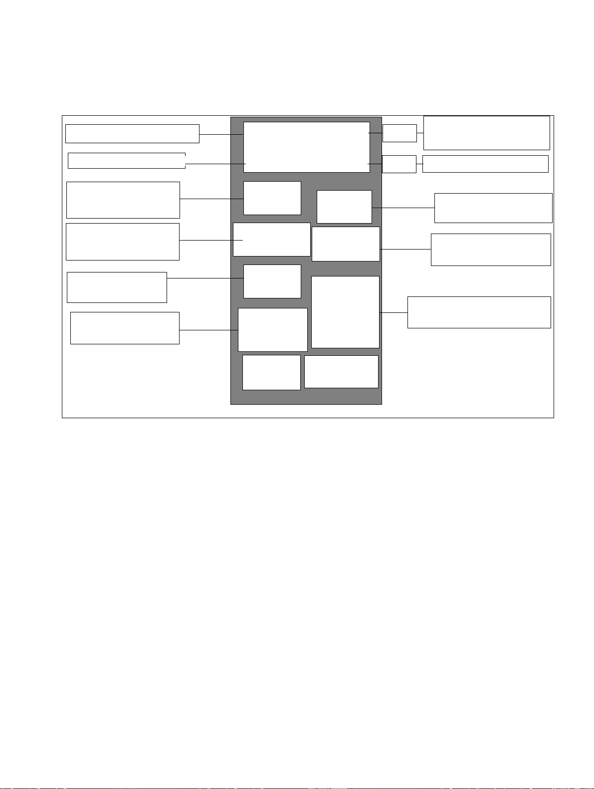
2.3 Configurations HiPath 1100
The systems HiPath 1100 are designed to meet the requirements for a wide range of clients
and are offered in the following configurations:
● HiPath 1120: Wallmount, standard configuration for 2 external lines, 8 extensions and 4
system telephone interfaces (KS).
● HiPath 1150: Wallmount, standard configuration for 2 external lines, 10 extensions and 8
system telephone interfaces (KS).
● The HiPath 1190 comes in two versions:
● HiPath 1190: with external cabinet accommodating up to 21 modules (expansion and
optional) comprising the MB, 2 backplanes, 3 power supplies (UPS).
● HiPath 1190R: with rack-mounting cabinet on a standard 19” rack, can accommodate
up to 21 modules (expansion and optional) in addition to the CPU, comprising the MB,
2 backplanes, 3 power supplies (UPS).
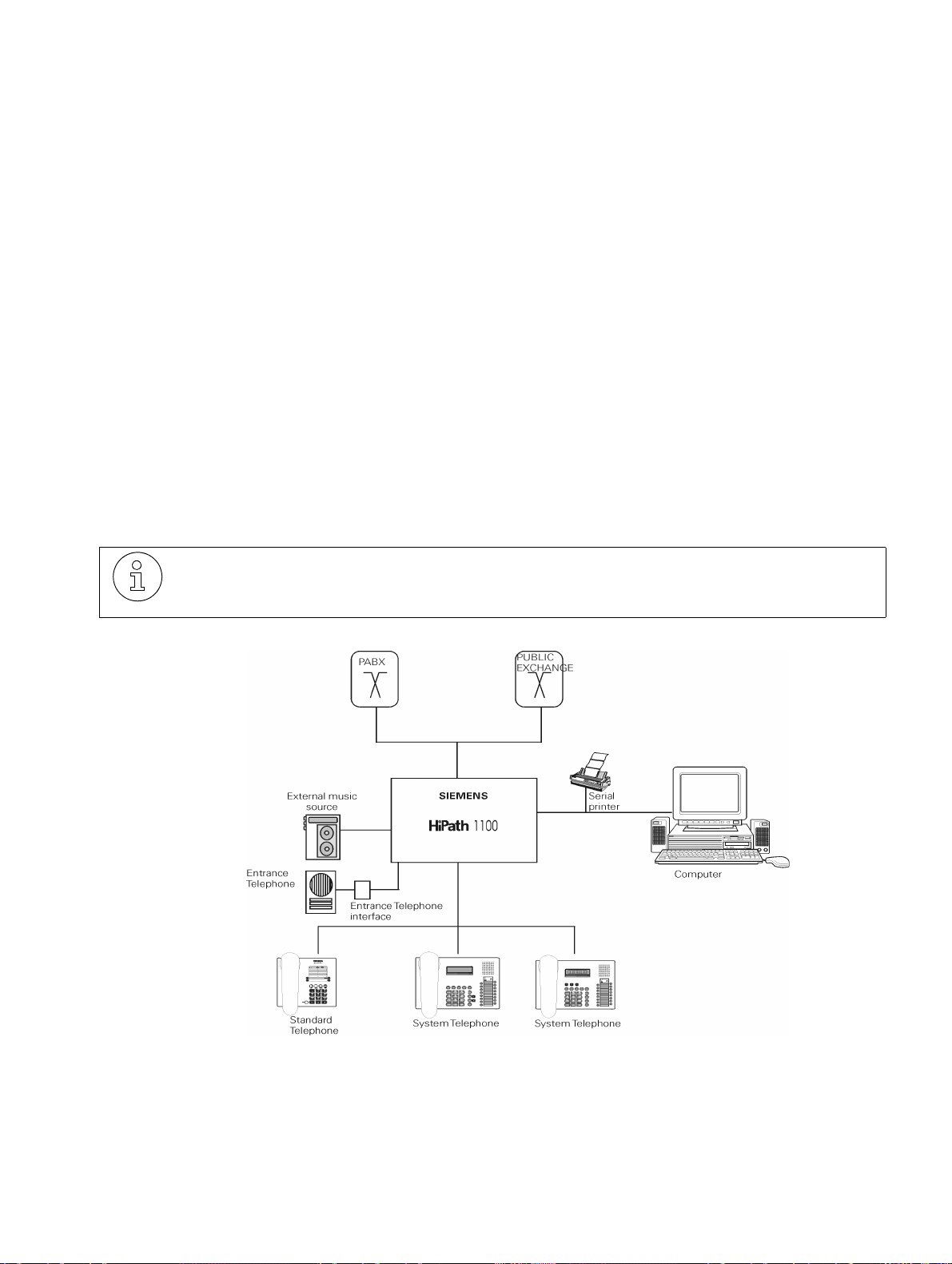
For information about country-specific versions please ask one of our distributors.
Figure 2-1 System Overview
Service Manual
2-25
Page 26
System Data
HiPath 1100 System Periphery
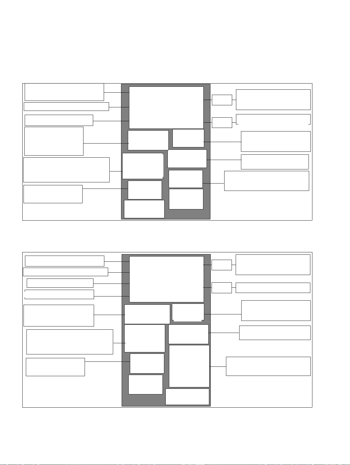
2.4 HiPath 1100 System Periphery
● HiPath 1120
System Telephones
External analog lines
Analog extensions
Sensor and Relay
Audio Device
Internal entrance telephone Extension
Basic Access
(Public Network)
C/D
A/B
S1 / RL1
ISDN
S
0
4 x
A/B
2 x
8 x
Music module MO
Entrance tele-
phone interface
S
EB
MO
CTR-U
EB
Figure 2-2 HiPath 1120 Periphery
● HiPath 1150
System Telephones
External analog lines
Analog extensions
External music source
Primary Access
(Public Network)
C/D
A/B
MOH
E1
A/B
8 x
2 x
10
Music
TME1
EB
MB
0
P0/E
MB
Mini DIN-6
Mini DIN-4
ADSL
MO
U
P0/E
EB
204 and
200
EVM
MO
Mini DIN-6
Mini DIN-4
ADSL
MO
MO
V.24
MO
USB
Ethernet
LAN
Service PC
Service PC
HUB - 4 PC Ports
optiPoint tele-
External analog lines
A/B
Analog extensions
MO
V.24
MO
USB
Service PC
Service PC
HUB - 4 PC Ports
Ethernet
LAN
Printer
Printer
U
P0/E
EB
010, 2 02,
206, 210,
012, 200,
400, 800
EB
optiPoint telephones
External analog lines
A/
Analog extensions
Internal entrance telephone Extension
Basic Access
(Public Network)
S
0
ISDN
Entrance
telephone
interface
S
0
EB
EVM
MO
CTR-U
P0/E
EB
Figure 2-3 HiPath 1150 Periphery
2-26 Service Manual
Page 27
System Data
HiPath 1100 System Periphery
● HiPath 1190
System telephones
External music source
System
telephones
Primary Access
(Public Network)
Basic Access
(Public Network)
Entrance telephone Extension
MOH
C/D
E1
S
0
ISDN
C/D
8 x
Music
CD 16
MO
TME1
EB
S
0
EB
Entrance
telephone
interface
EVM
MO
Mini DIN-6
MB
Mini DIN-4
ADSL
MO
U
010, 2 02,
206, 210,
012, 200,
400, 800
CTR-U
EB
P0/E
EB
EB
P0/E
MO
V.24
MO
USB
Ethernet
LAN
Service PC
Service PC
HUB - 4 PC Ports
optiPoint tele-
a/b
External analog lines
Analog extensions
Printer
phones
Figure 2-4 HiPath 1190 Periphery
Service Manual
2-27
Page 28

System Data
System expansion limitations
2.5 System expansion limitations
During system installation (see “Installing modules” on page 4-136) please consider
characteristics, recommendations and limitations of the modules that will comprise the final set.
We therefore recommend that you read this chapter carefully, where you will find the maximum
capacities of each module and how it interacts with the other components.
Basic configuration:
HiPath 1120
HiPath 1150
HiPath 1190
External analog lines 2 0
Analog extensions 8 10
System telephone
interface (KS)
Expansion modules:
*
4 8
EB 010 (10 extensions) 0 4 14
EB 012 (12 extensions) 0 3 11
EB 202 (2 external lines and 2 extensions) 0 4 16
EB 204 (2 external lines and 4 extensions) 2 0
EB 206 (2 external lines and 6 extensions) 0 4 16
EB 210 (2 external lines and 10
0 4 11
extensions)
EB 200 (2 external lines) 2 4 16
EB 400 (4 external lines) 0 3 10
EB 800 (8 external lines) 0 1 5
S0 module 1 2
TME1 module 0 1 2
U
module (optiPoint): 1 1 or 2
P0/E
(see “CTR-UP0/E module” on
page 3-77)
CD 16 module (KS) 0 1
Optional modules:
LAN interface modules
**
1
(ADSL, SLIMC, SADSLIM, LIMC or
ADSLIM)
EVM module 1
Music module 1 on board
TFE entrance telephone interface 20
Total System Capacity:
***
:
2-28 Service Manual
Page 29

System Data
System expansion limitations
Extension (analog + digital) 23 89 143
System Telephones (KS + optiPoint)
(see “CTR-UP0/E module” on page 3-77)
4 KS
or
8 optiPoint
(4 master + 4
slave)
8 KS
+
16 optiPoint
(8 master + 8
slave)
8 KS
+
16 optiPoint
(8 master + 8
slave)
or
24 KS (CD 16
module)
Digital line with TME1/Digital line with S00/2 30/10 45/20
External analog lines without TME1 or S
modules
Digital line (TME1) + analog line/digital line
6 16 40
0
0/8 32/16 45/44
(S0)+ analog line
* Each system telephone (KS) that is connected occupies one analog telephone slot.
** S0 and TME1 modules cannot be used simultaneously.
LAN and TME1 interface modules can be used simultaneously in HiPath 1150/1190.
- HiPath 1120 : ADSL modules, SLIMC and SADSLIM module
- HiPath 1150/1190 :ADSL modules, SLIMC and SADSLIM module
*** When the maximum capacity for external lines is exceeded due to the installation of EB, S0 or TME1 modules, the system
disables external analog lines. Extension slots, however, continue to operate as usual.
Example 1: HiPath 1150
- slot 0, MB 210,
- slot 1, EB 210,
- slot 3 TME1 - 30 digital lines
EB 210 external lines will not work, but extensions will. Since the system allows for a maximum number of 32 lines, we
cannot have any additional analog line.
Example 2: HiPath 1150
- slot 0, MB 210
- slot 3 TME1 = 30 digital lines
In this case, there are 32 external lines at most available on the system. This means there is no room for an additional EB
module with an external analog line.
30 CAS/S2 digital lines + 2 MB external analog lines = 32 external lines.
If an EB 200 was installed in slot 1 or slot 2 the module would not be operable, since it would exceed the system’s
maximum capacity for external lines.
Example 3: HiPath 1150
- slot 0, MB 210
- slot 3 TME1 = 10 digital lines
(WARNING: Deactivate digital line for the TME1 module and program unused digital lines on the switch as unavailable
(turn the switch off then on).
Overall, there are 12 external lines on the system. This means there are 4 additional external lines available before
reaching the maximum capacity of 16 external lines.
An additional EB 400 could be used in slot 1 or slot 2.
If an EB 800 were installed on the switch, the entire module would be inoperable since it would exceed the system’s
maximum capacity for external lines.
Table 2-1 Specific limitations to system expansion
Service Manual
2-29
Page 30

System Data
System expansion limitations
2.5.1 Considerations for digital lines
HiPath 1120
Maximum number of external lines allowed is 16 (S0 digital lines + external analog lines)
Settings External analog line S0 module digital line Total
MB + 1 EB 200 4 0 4
MB + 1 S0-2 2 4 6
MB + 1 S0-2 + 1 EB 200 4 4 8
Table 2-2 Considerations on S0 digital lines on the HiPath 1120
HiPath 1150
Maximum number of external lines allowed is 16 (S0 digital lines + external analog lines)
2-30 Service Manual
Page 31

System Data
System expansion limitations
Settings External analog line S0 module digital line Total
MB + 1 EB 800 10 0 10
MB + 1 EB 800 + 1 EB 400 + 1 EB 200 16 0 16
MB + 1 S0-2 2 4 6
MB + 1 S0-2 + 1 EB 800 + 1 EB 200 12 4 16
MB + 1 S0-5 2 10 12
MB + 1 S0-5 + 1 EB 400 6 10 16
Table 2-3 Considerations on S0 digital lines on the HiPath 1150
Capacity can be increased up to 32 external lines using a TME1 module (30 digital lines + 2
analog lines). In this case, an S0 module cannot be used. If 15 (or more) TME1 module
channels are occupied, then only 2 MB external analog lines may be used (e.g., 20 TME1
module digital lines + 2 MB external analog lines).
Settings External
analog line
Digital line (maximum
depending on the number of
Total
analog lines)
MB + 1 TME1 2 30 32
MB + 1 TME1 + 1 EB 200 4 13 17
MB + 1 TME1 + 1 EB 400 6 11 17
MB + 1 TME1 + 1 EB 800 10 7 17
MB + 1 TME1 + 1 EB 800 + 1 EB 200 12 5 17
MB + 1 TME1 + 1 EB 800 + 1 EB 400 14 3 17
Table 2-4 Considerations on TME1 digital lines on the HiPath 1150
HiPath 1190
Maximum number of external lines allowed is 45 (digital lines and/or external analog lines).
Maximum number of external analog lines is 40.
For example, the following configurations are available.
Configuration 1: 40 analog lines + 5 digital lines
Configuration 2: 8 analog lines + 37 digital lines
Configuration 3: 0 analog lines + 45 digital lines
Settings External
analog line
Digital line (depending on the
number of analog lines)
1 TME1 0 30 30
2 TME1 0 45 45
1 TME1 + 1 EB 200 2 30 32
2 TME1 + 1 EB 200 2 43 45
1 TME1 + 1 EB 400 4 30 34
2 TME1 + 1 EB 400 4 41 45
Service Manual
Total
2-31
Page 32

System Data
System expansion limitations
1 TME1 + 1 EB 800 8 30 38
2 TME1 + 1 EB 800 8 37 45
1 TME1 + 1 EB 800 + 1 EB 200 10 30 40
2 TME1 + 1 EB 800 + 1 EB 200 10 35 45
1 TME1 + 1 EB 800 + 1 EB 400 12 30 42
2 TME1 + 1 EB 800 + 1 EB 400 12 33 45
1 TME1 + 2 EB 800 16 29 45
2 TME1 + 2 EB 800 16 29 45
1 TME1 + 2 EB 800 + 1 EB 200 18 27 45
2 TME1 + 2 EB 800 + 1 EB 200 18 27 45
1 TME1 + 2 EB 800 + 1 EB 400 20 25 45
2 TME1 + 2 EB 800 + 1 EB 400 20 25 45
1 TME1 + 3 EB 800 24 21 45
2 TME1 + 3 EB 800 24 21 45
1 TME1 + 3 EB 800 + 1 EB 200 26 19 45
2 TME1 + 3 EB 800 + 1 EB 200 26 19 45
1 TME1 + 3 EB 800 + 1 EB 400 28 17 45
2 TME1 + 3 EB 800 + 1 EB 400 28 17 45
1 TME1 + 4 EB 800 32 13 45
2 TME1 + 4 EB 800 32 13 45
1 TME1 + 5 EB 800 40 5 45
2 TME1 + 5 EB 800 40 5 45
1 TME1 + 10 EB 400 40 5 45
2 TME1 + 10 EB 400 40 5 45
Table 2-5 Considerations on TME1 digital lines on the HiPath 1190
2.5.2 Considerations on system telephones
HiPath 1120
The table below shows the settings available for KS phones and optiPoint using U
Master/Slave/KS
None U
(2 Ports) U
P0/E
P0/E
(4 Ports)
0/0/4 2/2/2 4/4/2
Table 2-6 optiPoint and KS telephones for HiPath 1120.
Limitations:
The limit for KS telephones operating with optiPoint telephones in the system is 2 (KS).
2-32 Service Manual
P0/E MODULES
:
Page 33

System Data
System expansion limitations
HiPath 1150/1190
The table below shows the settings available for KS with optiPoint using U
P0/E MODULES
:
Master/Slave/KS
None U
(2 Ports) U
P0/E
(4 Ports) U
P0/E
P0/E
(8 Ports)
None 0/0/8 2/2/8 4/4/8 8/8/8
U
U
U
(2 Ports) 2/2/8 4/4/8 6/6/8 2/2/8
P0/E
(4 Ports) 4/4/8 6/6/8 8/8/8 4/4/8
P0/E
(8 Ports) 8/8/8 8/8/8 8/8/8 8/8/8
P0/E
Table 2-7 optiPoint and KS telephones for HiPath1150/1190/1190R.
Limitations:
If an 8-port U
system. Both the HiPath 1150 and the HiPath 1190 allow a maximum of 8 U
module is installed, the system will not free up another U
P0/E
module in the
P0/E
ports, resulting
P0/E
in 16 optiPoint telephones (master + slave) + 8 KS telephones, for a total limit of 24 system
telephones. Therefore, only combinations of UP0/E modules are possible for a maximum of 8
ports.
2.5.3 Notes on HiPath 1150
If there are only 2 PCM highways in the HiPath 1150 and one module TME1 is used, we would
have 30 timeslots reserved and a further 2 timeslots reserved for the analog trunks, which
would mean fewer than 32 timeslots free for all the other extensions of the system. To avoid
this limitation, the solution was to use an additional highway based on the DSP control for slots
3 and 4.
SLOT 2
SLOT 1
Figure 2-5 Distribution of the highways in the HiPath 1150
SLOT 4
SLOT 3
Highway A
Highway B
Highway C
Service Manual
2-33
Page 34

System Data
System expansion limitations
PCMs are first allocated by connecting a codec in a channel and then letting the DSP transfer
this channel to another. The codec can only be connected in 2 highways, and so to interlink the
codecs with the third highway (c) it is necessary to proceed as with the first highway. The
highway (A) will not be used in this case.
The HiPath 1150 works with the dynamic allocation of timeslots during system start-up except
for some fixed resources, such as: EVM.
2.5.4 Notes on HiPath 1190
● The HiPath 1190 single rack system supports up to 80 extensions
● TME 1 module
This must only be mounted in slots 1 and 11. The system must therefore have both racks
mounted in order to run two modules.
Within the maximum limit of 40 external analog lines or 45 digital lines and 140 extensions,
the system may consist of, for example:
Slot Modules
1 and 2 2 x EB 800, 2 x EB 012 or 2 x EB 210 or 1 x TME1 in slot 1 (in this case slot 2
must remain Free).
3, 4 and 14 The module configuration for extensions or external lines must not exceed 32
ports (e.g., 3 x EB 010 or 2 x EB 012 or 2 x EB 210).
5, 6 and 7 The module configuration for extensions or external lines must not exceed 32
ports.
8, 9 and 10 The module configuration for extensions or external lines must not exceed 32
ports.
11, 12 and 13Module configuration for extensions or external lines must not exceed 32 ports,
or 1 x TME1 in slot 11 and 1 x EB 010, EB 012 or EB 210 in slot 13 (in this case,
slot 12 must be left Free).
15, 16 and 17The module configuration for extensions or external lines must not exceed 32
ports.
18, 19 and 20The module configuration for extensions or external lines must not exceed 32
ports.
Table 2-8 Examples of system configurations HiPath 1190
Each of the system’s Highway supports up to 32 ports. For example, Highway 2
(slots 3, 4, and 14) can accommodate two EB 800 and one EB 206, totaling 24 ports.
For Highway 1 (slots 1 and 2), when a TME1 module is placed in slot 1 (totaling 30
ports), slot 2 must remain free (except for a LAN interface module, which can be installed in slot 2).
2-34 Service Manual
Page 35

System Data
System expansion limitations
Table 2-9 shows the slots and their Highways.
Slot 11 12 13 14 15 16 17 18 19 20
Highways
2 X
5 X X X
6 X X X
7 X X X
Slot 01 02 03 04 05 06 07 08 09 10
Highways
1 X X
2 X X
3 X X X
4 X X X
Table 2-9 Distribution of modules on the HiPath 1190 backplanes
Service Manual
2-35
Page 36

System Data
Technical Data
2.6 Technical Data
Element HiPath 1120 HiPath 1150 HiPath 1190
Standard Cabinet Size
Length 360 mm (14.17") 470 mm
(18.50")
Depth 288 mm (11.33") 14.17" (370
mm)
420 mm
(16.53")
394 mm
(15.51")
Height 64.4 mm (2.53") 100 mm (3.93") 498 mm
(19.60")
Weight 1.2 kg (2.64 lb) 4.25 kg (2.64
lb)
22.5 kg (49.60
lb)
Electrical specifications for power supply units (PSUs)
Power Requirements (Input) 220V / 127mA
127V / 331mA
110 - 230V, Full range / 1.5A
110V / 381mA
Operating Frequency 50/60Hz 50/60Hz
Rated Voltage (Output) U1: 8 Vrms
U2: 23 Vrms
5.1 VDC .
26.4 VDC .
Call Voltage U3:
65 V
42 V
40 V
rms
rms
/60Hz
rms
/25Hz (SPA)
/25Hz (RSA)
50 VAC + 97 V
42 VAC + 85.8 V
(RSA)
/ 0.13A - 25Hz
DC
/ 0.13A - 25Hz
DC
Dialing modes for calls to other public or private exchanges:
● MF Transmission Level:
Lower Group* -11 dBm
Higher Group* -9 dBm
Pre-Emphasis 2 dB
Pulse Duration** 90ms min.
Inter-digit pause** 90ms min.
● DP (Dial Pulse):
Pulse/Pause Ratio** 2:1 (approximately 70:30ms = 10 Hz)
Inter-digit Pause** 800ms
2-36 Service Manual
Page 37

System Data
Technical standards and compliance
Element HiPath 1120 HiPath 1150 HiPath 1190
Open loop isolation
resistance between A/B or a/
> 10MΩ
ground or b/ground
Closed loop line resistance/
continuous loop current
Incoming Call Detection > 9V
*〉 Values vary according to the country. The values shown are specifically for Brazil.
**〉 Values depend on the country settings, which are configurable. The values shown are default values for Brazil.
Complies with national requirements/standards
RMS
Table 2-10 Technical Data
Values shown are approximate. When making connections, consider the specific
level of tolerance that applies.
2.7 Technical standards and compliance
Compliance Standard Note
EN60950
Electrical Safety
IEC 60950
UL 60950-1
Environmental Conditions IEC 721 *
IEC61000-4-5
Power Surge
(IEC 801-5)
Level 3
TIA-968-A
Fast Transients
Static electricity discharge
*〉 Weather conditions: Operation 3K3 Transportation 2K4 Storage 1K3.
Mechanical: Operation 3M3 Transportation 2M2 Storage 1M2.
IEC61000-4-4
(IEC 801-4)
IEC61000-4-2
(IEC 801-2)
Level 3
Air - Level 3 (8kV)
Contact - Level 2 (4kV)
Table 2-11 Standards and compliance
Service Manual
2-37
Page 38

System Data
Technical standards and compliance
2.7.1 International Safety Standard
● IEC 60950
2.7.2 Environmental conditions
Operation Transportation Storage
Air Temperature (theF) +41 to +86 -13 to +158 41 to +113
Relative humidity 5% to 85 % 95% 5% to 95%
Table 2-12 Environmental conditions
Servicing conditions (mechanical)
● This system was essentially designed for installation at a fixed location.
Warning
!
● Tthe avoid condensation when shipping the system in extremely low
temperatures, keep the equipment in its packaging until it reaches room
temperature. Proceed thereafter with the installation (acceptable temperature
range: 7.5°C (45.5°F)/30 min)
● Do not expose the equipment to direct sunlight or place it near any heat sources
(to avoid a localized increase of temperature)
● Make sure the installation area is dry. During system operation avoid any
conditions that may cause condensation.
● Forced ventilation is not required.
● Do not block the natural flow of air around the equipment.
● Do not expose the equipment to the weather.
2-38 Service Manual
Page 39

System Data
Documentation list
2.8 Documentation list
Documentation Order number
Programming manual - DTMF telephones A31003-K1270-U100-*-**19
User Manual - optiPoint 500 system telephone - Adv, Std,
A31003-K1270-U101-*-**19
Basic and Econ
User Manual - Profiset 3030 and E822 ST system
A31003-K1270-U102-*-**19
telephones
User Manual - DTMF telephones and Pulse telephones A31003-K1270-U103-*-**19
User Manual - optiPoint 500 system telephone - Entry A31003-K1270-U104-*-**19
Quick Reference Guide - DTMF telephones and Pulse
A31003-K1270-U105-*-**19
telephones
Quick Reference Guide - optiPoint 500 system telephone -
A31003-K1270-U106-*-**19
Entry
Quick Reference Guide - optiPoint 500 system telephone -
A31003-K1270-U107-*-**19
Adv, Std, Basic and Econ
Quick Reference Guide - Profiset 3030 and E822ST system
A31003-K1270-U108-*-**19
telephones
Attendant Console - optiPoint 500 system telephone - Adv,
A31003-K1270-U109-*-**19
Std, Basic, Econ and Entry
Attendant Console - Profiset 3030 and E822 ST system
A31003-K1270-U110-*-**19
telephones
Service Manual A31003-K1270-S100-*-**20
Manager A31003-K1270-M100-*-**A9
Options (Brazil)
Interaction Center Smart User Manual A30808-X5226-E175-*-7618
TAC Smart Quick Reference Guide A30808-X5226-V103-*-7619
Table 2-13 Documentation list for HiPath 1100
Service Manual
2-39
Page 40

Modules
Overview
3 Modules
3.1 Overview
About this Chapter
This chapter covers the following topics:
Topic Page
Abbreviations for Country names 3-41
List of modules 3-41
Modules/components
● Motherboard (MB) 3-47
● Expansion modules (EB) 3-55
● S0 module 3-63
● TME1 module 3-67
● UP0/E module and CTR UP0/E module 3-75
Optional modules
● LAN interface modules 3-78
● EVM module 3-86
● CD 16 module 3-88
● Music module 3-89
General modules/components
● Power Supply Unit (PSU) 3-91
● Main Distribution Frame 3-98
● Backplane 3-99
● Internal entrance telephone with TFE interface 3-101
● V.24 Adapter Cable 3-111
● USB adapter cable 3-114
● TME1 Serial Cable 3-115
● Adapter cable for analog modem 3-116
● TME1 Coax Cable 3-118
● Battery interconnect cables (BBU) 3-120
3-40 Service Manual
Page 41

Modules
Abbreviations for Country names
3.2 Abbreviations for Country names
BRA Brazil
IM International Market
RSA South Africa
ARG Argentina
SPA Spain
IND India
RUS Russia
UK United Kingdom
AUS Australia
Table 3-1 Abbreviations for Country names:
3.3 List of modules
List of modules/components - HiPath 1120
Module / component Reference
BOX
HiPath 1120 S30817-U857-B401-* (IM) :110V
S30817-U857-A401-* (IM) :220V
S30817-U857-C401-* (ARG)
S30817-U857-A412-* (SPA)
S30817-U857-A464-* (IND)
S30817-U857-A497-* (RSA)
S30817-U857-A408-* (UK)
S30817-U857-A400-* (AUS)
Motherboard (MB)
MB S30817-Q845-A401-* (IM)
S30817-Q845-A464-* (IND)
S30817-Q845-A497-* (RSA)
Service Manual
3-41
Page 42

Modules
List of modules
Module / component Reference
Expansion module
EB 204 S30817-H844-A401-* (IM)
S30817-H844-A464-* (IND)
S30817-H844-A497-* (RSA)
EB 200 S30817-H844-B401-* (IM)
S30817-H844-B464-* (IND)
S30817-H844-B497-* (RSA)
S0 module (2 ports)
S0 module (1 port)
U
module (4 ports)
P0/E
U
module (2 ports)
P0/E
CTR U
module S30817-Q862-A401-*
P0/E
S30817-H843-A301-*
S30817-H843-B301-*
S30817-H863-A401-* (IM)
S30817-H863-B401-* (IM)
Optional modules (MO)
EVM module S30807-Q6945-X-*
ADSL module S30817-H842-A301-* (IM)
SLIMC module S30817-H866-A401-* (IM)
SADSLIM module S30817-H866-B401-* (IM)
Music module S30817-H860-A301-* (IM)
Internal entrance telephone with TFE
See Note 1
interface
General Components
V.24 Adapter Cable S30122-X5468-X005-*
USB adapter cable S30817-K861-A301-*
Impedance adapter (Balun) - TME1 S30122-X7357-X-*
Power Supply Unit (PSU) 110/127V:
S30122-X8009-X100-* (IM)
220V:
S30122-X7646-X-* (IM)
S30122-X7646-X200-* (ARG/AUS)
S30122-X8009-X005-* (SPA/RUS)
S30122-X8009-X006-* (RSA)
S30122-X7646-X300-* (UK)
Interconnect cable (flat cable) - with Ferrite C39195-A7700-B6
Interconnect cable (flat cable) - without
C39195-Z7001-C95
Ferrite
3-42 Service Manual
Page 43

Modules
List of modules
Module / component Reference
Ferrite for C95 interconnect cable C39022-Z7000-C15
Interconnect cable (flat cable)- U
Additional power supply - U
*) Module/component version.
P0/E
P0/E
C39195-Z7001-C96
C39280-Z4-C71
Table 3-2 List of modules/components - HiPath 1120
Note 1: See “Internal entrance telephone with TFE interface” on page 3-101
TFE entrance telephone interface S30122-K7696-T313-* with an amplifier)
TFE entrance telephone interface S30817-K930-A300-* without an amplifier)
entrance telephone interface, Brazil, S30817-Q936-C282
List of modules/components - HiPath1150/1190/1190R
Module / component Reference
BOX
HiPath 1150 S30817-U853-A401-* (IM)
S30817-U853-A497-* (RSA)
S30817-U853-A464-* (IND)
S30817-U853-A400-* (AUS)
HiPath 1190 Full (2 shelves)
S30777-U770-A401-* (IM)
S30777-U770-A464-* (IND)
S30777-U770-A400-* (AUS)
S30777-U770-A497-* (RSA)
Medium (1 shelf)
S30777-U770-B401-* (IM)
S30777-U770-B464-* (IND)
S30777-U770-B400-* (AUS)
S30777-U770-B497-* (RSA)
Service Manual
3-43
Page 44

Modules
List of modules
Module / component Reference
HiPath 1190R Full (2 shelves)
S30777-U770-C401-* (IM)
S30777-U770-C464-* (IND)
S30777-U770-C400-* (AUS)
S30777-U770-C497-* (RSA)
Medium (1 shelf)
S30777-U770-D401-* (IM)
S30777-U770-D464-* (IND)
S30777-U770-D400-* (AUS)
S30777-U770-D497-* (RSA)
Expansion Kit HiPath 1190
Power Supplies, Cables and backplanes S30777-H770-B497-* (RSA)
S30777-H770-B401-* (IM)
Motherboard (MB) HiPath 1150
MB S30817-Q848-B401-* (IM)
S30817-Q848-B464-* (IND)
S30817-Q848-B497-* (RSA)
MB HiPath 1190
MB S30817-Q856-A401-* (IM)
S30817-Q856-A464-* (IND)
Expansion modules
EB 010 S30817-H858-B301-* (IM)
S30817-H858-B397-* (RSA)
EB 012 (HiPath 1150 only) S30817-H858-A301-* (IM)
S30817-H858-A397-* (RSA)
EB 202 S30817-H847-C301-* (IM)
S30817-H847-C364-* (IND)
S30817-H847-C397-* (RSA)
EB 206 S30817-H847-B301-* (IM)
S30817-H847-B364-* (IND)
S30817-H847-B397-* (RSA)
EB 210 S30817-H847-A301-* (IM)
S30817-H847-A364-* (IND)
S30817-H847-A397-* (RSA)
EB 200 S30817-H850-C301-* (IM)
S30817-H850-C364-* (IND)
S30817-H850-C397-* (RSA)
3-44 Service Manual
Page 45

Modules
List of modules
Module / component Reference
EB 400 S30817-H850-B301-* (IM)
S30817-H850-B364-* (IND)
S30817-H850-B397-* (RSA)
EB 800 S30817-H850-A301-* (IM)
S30817-H850-A364-* (IND)
S30817-H850-A397-* (RSA)
S0 module (5 ports)
S0 module (2 ports)
S30817-H851-A301-*
S30817-H851-B301-*
TME1 module S30817-H846-A282-*
U
module (8 ports)
P0/E
U
module (4 ports)
P0/E
U
module (2 ports)
P0/E
CTR U
module S30817-Q862-A401-*
P0/E
S30817-H864-A401-*
S30817-H864-B401-*
S30817-H864-C401-*
Optional modules (MO)
ADSL module S30817-H849-A282-*
LIMC module S30817-H867-A401-* (IM)
ADSLIM module S30817-H867-B401-* (IM)
EVM module S30817-Q6945-X-*
CD 16 module S30817-H0855-A282-*
Internal entrance telephone with TFE
See Note 2
interface
General Components
Coax Cable for TME1 module C39195-A9700-B531-*
TME1 Serial Cable C39195-A9700-B532-*
V.24 Adapter Cable S30122-X5468-X005-*
Impedance adapter (Balun) S30122-X7357-X-*
USB adapter cable S30817-K861-A301-*
Interconnect cable, 250 mm (included with
V42405-J1-A159
ADSL module)
Power cable C39195-Z7001-C11
C39195-Z7001-C12
Ferrite for power cable C39022-Z7000-C7
Battery interconnect cable (BBU) C39195-A7700-B11
Interconnect cable between batteries (BBU) C39195-A7944-B49
Service Manual
3-45
Page 46

Modules
List of modules
Module / component Reference
Interconnect cable between PSU-batteries
C39195-A7700-B9
(BBU)
Interconnect cable for HiPath 1190 power
C39195-A7700-B10
supply (BBU)
Vshare cable for HiPath 1190 (BBU) C39195-A7700-B8
Power Supply Unit (PSU)
HiPath 1150 S30122-K7642-X10-* (IM, AUS and IND)
S30122-K7642-X30-* (RSA)
With BBU (Battery Backup Unit)
S30817-U853-A400-* (B AUS)
S30817-U853-B401-* (IM )
S30817-U853-B464-* (IND)
HiPath 1190 S30122-K7642-X200-* (IM, AUS and IND)
S30122-K7642-X300-* (RSA)
Full with BBU (Battery Backup Unit)
S30777-U770-E400-* (AUS)
S30777-U770-E401-* (IM )
S30777-U770-E464-* (IND)
Medium with BBU (Battery Backup Unit)
S30777-U770-F400-* (AUS)
S30777-U770-F401-* (IM )
S30777-U770-F464-* (IND)
HiPath 1190R S30122-K7642-X200-* (IM, AUS and IND)
S30122-K7642-X300-* (RSA)
Full with BBU (Battery Backup Unit)
S30777-U770-G400-* (AUS)
S30777-U770-G401-* (IM )
S30777-U770-G464-* (IND)
Medium with BBU (Battery Backup Unit)
S30777-U770-H400-* (AUS)
S30777-U770-H401-* (IM )
S30777-U770-H464-* (IND)
Expansion Kit with BBU (Battery Backup Unit)
HiPath 1150
S30817-H853-B401-*
Power supply and cables
HiPath 1190/1190R
Power supply and cables
Full
S30777-H770-H410-*
Medium
S30777-H770-H420-*
3-46 Service Manual
Page 47

Modules
Motherboard (MB)
Module / component Reference
Backplane
HiPath 1150 S30817-Q853-A401-*
HiPath 1190 (backplane 1)
HiPath 1190 (backplane 2)
S30817-Q854-A401-*
S30817-Q854-B401-*
Table 3-3 List of modules/components - HiPath1150/1190/1190R
Note 1: HiPath 1100 For further details on the system’s total capacity see Table 2-1 on page
2-29 “Specific limitations to system expansion.”
Note 2: See “Internal entrance telephone with TFE interface” on page 3-101
● TFE entrance telephone interface S30122-K7696-T313-*(with an amplifier)
● TFE entrance telephone interface S30817-K930-A300-*(without an amplifier)
● entrance telephone TFE S30817-Q936-C282-* (Brazil)
Warning
!
Before inserting or removing any of the modules on the HiPath 1100, make
sure power is turned off.
3.4 Motherboard (MB)
Introduction
The MB is the main board for the HiPath 1100 system. The MB provides all functions required
for PABX operation.
Functions
● CLIP - external calling number identification (service must be provided by local carrier)
● Central Processing Unit (CPU)
● DTMF generator and detector
● Conference circuits
● Tone generators
● Music source
● Memory (software + client’s data base)
Service Manual
3-47
Page 48

Modules
Motherboard (MB)
● Digital switch
● Signaling
● Fax/DID.
● System’s date and time.
Note
With backup power from a battery, date and time settings are not lost in the event of a power
outage. Replace this battery with an identical type of battery or use a type recommended by
Technical Support.
Caution
FAILURE TO REPLACE BATTERY WITH SPECIFIED BATTERY TYPE CAN CAUSE
!
RISK OF EXPLOSION. DISPOSE OF USED BATTERIES ACCORDING TO YOUR
COUNTRY’S LAWS AND REGULATIONS.
3-48 Service Manual
Page 49

Modules
Motherboard (MB)
3.4.1 HiPath 1120
If the UP
!
MB Interfaces
available.
module is connected on the HiPath 1120 , only 2 CD interfaces will be
0/E
Battery
Figure 3-1 HiPath 1120’s MB
Service Manual
3-49
Page 50

Modules
Motherboard (MB)
Motherboard Connector assignments - HiPath 1120
Contact X14 Connector X20 Connector X30 Connector X40
Battery
Connector
1 a1 - trunk 1 a1 - extension 1 a5 - extension 5 C-interface 1 Supplies power
2 b1 - trunk 1 b1 - extension 1 b5 - extension 5 D-interface 1
for maintaining
the system’s
3 a2 - trunk 2 a2 - extension 2 a6 - extension 6 C-interface 2
4 b2 - trunk 2 b2 - extension 2 b6 - extension 6 D-interface 2
5 a3 - extension 3 a7 - extension 7 C-interface 3
date and time
settings in the
event of a power
outage.
6 b3 - extension 3 b7 - extension 7 D-interface 3
7 a4 - extension 4 a8 - extension 8 C-interface 4
8 b4 - extension 4 b8 - extension 8 D-interface 4
X1 Connector X2 Connector X50 Connector X60
X70 Connector
Connector
Ribbon cable for
modules
X90 and X91
Connector
Additional ribbon
cable for EB-
U
P0/E
USB
interface
V.24 serial
interface
X92 Connector X93 Connector X94
Connector
Power Supply
Unit (PSU)
X95 Connector
For a VCC
module
For an EVM
module
CTR U
P0/E
Table 3-4 HiPath 1120 MB Connector assignments
For Music
module
For LAN
Interface
module
3-50 Service Manual
Page 51

Modules
Motherboard (MB)
Baby Board VCC module interface
This module is connected on the MB and is an AC/DC converter used in HiPath 1120 V6.0 and
V7.0. Input voltages are 23V AC and the ring voltage, which depends on the country. Output
voltages are: 3.3VDC, 5 VDC, 24VDC, 32VDC and the ring voltage added to the offset voltage.
Figure 3-2 HiPath 1120 Baby Board VCC module
Baby Board VCC module Connector assignments
X1 and X2 Connectors
Connects to MB through a pin Connector
Table 3-5 Baby Board VCC module Connectors HiPath 1120
Service Manual
3-51
Page 52

Modules
Motherboard (MB)
3.4.2 HiPath 1150
MB Interfaces
Battery
Figure 3-3 Overview of the HiPath 1150 MB
3-52 Service Manual
Page 53

Modules
Motherboard (MB)
MB Connector assignments (HiPath 1150)
Contact X5
Connector
1 a1 - trunk 1 a3 -
2 b1 - trunk 1 b3 -
3 a2 - trunk 2 a4 -
4 b2 - trunk 2 b4 -
5 a1 - extension 1a5 -
6 b1 - extension 1b5 -
7 a2 - extension 2a6 -
8 b2 - extension 2b6 -
X6
Connector
extension 3
extension 3
extension 4
extension 4
extension 5
extension 5
extension 6
extension 6
X7
Connector
a7 - extension
X8
Connector
-- C-interface 1 C-interface 5
7
b7 - extension
-- D-interface 1 D-interface 5
7
a8 - extension 8Music - A
wire
b8 - extension 8Music - B
wire
a9 - extension
9
b9 - extension
9
a10 extension 10
b10 extension 10
X11
Connector
X12
Connector
C-interface 2 C-interface 6
D-interface 2 D-interface 6
C-interface 3 C-interface 7
D-interface 3 D-interface 7
C-interface 4 C-interface 8
D-interface 4 D-interface 8
Connector
X212
Backplane,
slot 1 and 2
Connector
Connector
port
Power
supply (PSU)
Battery
Connector
port
Backplane
Slot 3 and 4
Connector X1Connector X9Connector
CTR-U
P0/E
module
X31
Supplies power for
maintaining the system’s
EVM module
date and time settings in the
event of a power outage.
Table 3-6 HiPath 1150 Motherboard Connector assignments
Interface
USB
X10
V.24 serial
interface
Service Manual
3-53
Page 54

Modules
Motherboard (MB)
3.4.3 HiPath 1190/1190R
MB Interfaces
Battery
Figure 3-4 Overview of the HiPath 1190 MB
3-54 Service Manual
Page 55

Modules
Expansion modules (EB)
MB Connector assignments (HiPath 1190)
Contact X16
Connector
X17
Connector
X8 Connector Battery
1 C-interface 1 C-interface 5 Music - A wire
Supplies
2 D-interface 1 D-interface 5 Music - A wire
3 C-interface 2 C-interface 6 Music - B wire
4 D-interface 2 D-interface 6 Music - B wire
power for
maintaining
the system’s
date and time
5 C-interface 3 C-interface 7
6 D-interface 3 D-interface 7
7 C-interface 4 C-interface 8
settings in the
event of a
power outage.
8 D-interface 4 D-interface 8
X1 Connector X9 Connector X31
Backplane
Connector
USB Interface CTR-U
module
P0/E
Connector
V.24 serial
interface EVM module
Table 3-7 HiPath 1190 Motherboard Connector assignments
X14
X213
Connector
3.5 Expansion modules (EB)
Introduction
These modules consist of extensions and external analog lines for expanding the number of
analog interfaces (A/B) for standard telephones, analog trunks and additional equipment (TFE
interface, and others).
There are modules with only trunks, trunks and extensions and only extensions. For modules
with trunks and extensions, in the event of a power outage, there is a circuit that switches the
available trunks to their respective slots on the extensions.
3.5.1 HiPath 1120
Limitations
● 200 - 2 external analog lines
● 204 - 2 external analog lines and 4 analog extensions.
Service Manual
3-55
Page 56

Modules
Expansion modules (EB)
EB 200 Expansion module
Interfaces
Figure 3-5 EB 200 module overview
Figure 3-5 shows the distribution of extensions and external lines associated with the EB 200
module Connectors.
EB 200 Connector assignments
Contact X6 Connector X5 Connector
1 Connects to the
2 b1 - external line 1
MB through an
a1 - external line 1
interconnect
3 a2 - external line 2
cable (flat cable)
4 b2 - external line 2
Table 3-8 EB 200 Connector assignments
3-56 Service Manual
Page 57

Modules
Expansion modules (EB)
EB 204 Expansion module
Interfaces
Figure 3-6 EB 204 module overview
Figure 3-6 shows the distribution of extensions and external lines associated with the EB 204
module Connectors.
EB 204 Connector assignments
Contact X1 Connector X2 Connector X5 Connector
1 Connects to the
2 b1 - extension 1 b1 - external line 1
MB through an
a1 - extension 1 a1 - external line 1
interconnect
3 a2 - extension 1 a2 - external line 2
cable (flat cable)
4 b2 - extension 2 b2 - external line 2
5 a3 - extension 3
6 b3 - extension 3
7 a4 - extension 4
8 b4 - extension 4
Table 3-9 EB 204 Connector assignments
Service Manual
3-57
Page 58

Modules
Expansion modules (EB)
3.5.2 HiPath1150/1190/1190R
Limitations
● 800 - 8 external analog lines
● 400 - 4 external analog lines
● 200 - 2 external analog lines
● 210 - 2 external analog lines and 10 analog extensions
● 206 - 2 external analog lines and 6 analog extensions
● 202 - 2 external analog lines and 2 analog extensions
● 012 - 12 analog extensions
● 010 - 10 analog extensions.
EB 210, EB 206 and EB 202 expansion modules
Interfaces
Figure 3-7 EB 210 module overview
Figure 3-7 shows the distribution of extensions and external lines associated with the EB 210
module Connectors. The distribution associated with the EB 206 and 202 modules is limited by
their capacity.
3-58 Service Manual
Page 59

Modules
Expansion modules (EB)
Connector assignments for EB 210, EB 206 and EB 202 modules
Contact X1 Connector X2 Connector X3
Connector
1 Connection to
MB through
2 b1 - external line 1 b3 -
backplane
Connector
a1 - external line 1 a3 -
extension 3
extension 3
3 a2 - external line 2 a4 -
extension 4
4 b2 - external line 2 b4 -
extension 4
5 a1 - extension 1 a5 -
extension 5
6 b1 - extension 1 b5 -
extension 5
7 a2 - extension 2 a6 -
extension 6
8 b2 - extension 2 b6 -
extension 6
X4 Connector
a7 - extension
7
b7 - extension
7
a8 - extension
8
b8 - extension
8
a9 - extension
9
b9 - extension
9
a10 -
extension 10
b10 -
extension 10
Table 3-10 Connector assignments for modules EB 210, EB 206 and EB 202
Note 1: X2 Connector used for EB 210, EB 206, and EB 202 X3 Connector used for EB 210
and EB 206 X4 Connector for EB 210.
Service Manual
3-59
Page 60

Modules
Expansion modules (EB)
EB 012 and EB 010 expansion modules
Interfaces
Figure 3-8 EB 012 module overview
Figure 3-8 shows the distribution of extensions and external lines associated with the EB 012
module Connectors. The distribution associated with the EB 010 module is limited by its
capacity.
3-60 Service Manual
Page 61

Modules
Expansion modules (EB)
Connector assignments for the EB 012 and EB 010 modules
Contact X1 Connector X2 Connector X3
Connector
1 Connection to
MB through
2 b1 - extension 1 b5 -
backplane
Connector
a1 - extension 1 a5 -
extension 5
extension 5
3 a2 - extension 2 a6 -
extension 6
4 b2 - extension 2 b6 -
extension 6
5 a3 - extension 3 a7 -
extension 7
6 b3 - extension 3 b7 -
extension 7
7 a4 - extension 4 a8 -
extension 8
8 b4 - extension 4 b8 -
extension 8
X4 Connector
a9 - extension 9
b9 - extension 9
a10 - extension 10
b10 - extension 10
a11 - extension 11
b11 - extension 11
a12 - extension 12
b12 - extension 12
Table 3-11 EB 012 and EB 010 Connector assignments
Note 1: X4 Connector uses contacts 5 through 8 on the EB 012 only.
Service Manual
3-61
Page 62

Modules
Expansion modules (EB)
EB 800, EB 400 and EB 200 expansion modules
Figure 3-9 EB 800 module overview
Figure 3-9 shows the distribution of extensions and external lines associated with the EB 800
module Connectors. The distribution associated with the EB 400 and EB 200 modules is limited
by their capacity.
Connector assignments for EB 800, EB 400 and EB 200 modules
Contact X1 Connector X2 Connector X3 Connector
1 Connection to
2 b1 - external line 1 b5 - external line 5
MB through
a1 - external line 1 a5 - external line 5
backplane
3 a2 - external line 2 a6 - external line 6
Connector
4 b2 - external line 2 b6 - external line 6
5 a3 - external line 3 a7 - external line 7
6 b3 - external line 3 b7 - external line 7
7 a4 - external line 4 a8 - external line 8
8 b4 - external line 4 b8 - external line 8
Table 3-12 EB 800, EB 400 and EB 200 Connector assignments
Note 1: Modules EB 800, 400, and 200 do not have circuit breakers for power outages.
X2 Connector used for EB 800, EB 400, and EB 200
X3 Connector used for EB 800.
3-62 Service Manual
Page 63

Modules
Expansion modules (EB)
3.5.3 S0 module
Introduction
This module provides access to ISDN networks and network resources through 2/5 S0
standard digital access channels (4 or 10).
Functions
● Each ISDN access provides 2 64 Kbits/s channels, which are used for communication
● Depending on whether your carrier has enabled them, some features such as Caller ID,
Caller ID Blocking, Direct dialing to extensions and so on may be provided.
3.5.3.1 HiPath 1120
Interfaces
Figure 3-10 S0 HiPath 1120 module
The Figure 3-10 features a 2-Port S0 module, also available as a single-Port option.
Jumpers
Port 1
X2 and X3
Port 2
X4 and X5
Slot 1 and 2 - without RT (resistive termination) (factory default)
Slot 3 and 2 - with RT (resistive termination used when the port is configured as S0-BUS)
Table 3-13 HiPath 1120 S0 module jumpers
Service Manual
3-63
Page 64

Modules
Expansion modules (EB)
S0 module Connector assignments
X1 Connector Port 1
Port 2
X6
Connector
Connector
Connection to the MB is through a pin Connector RJ 45 RJ 45
Table 3-14 S0 module Connectors for HiPath 1120
X7
3-64 Service Manual
Page 65

Modules
Expansion modules (EB)
3.5.3.2 HiPath1150/1190/1190R
X1
Figure 3-11 Module S0 HiPath1150/1190/1190R
The Figure 3-11 features a 5-Port S0, also available as a 2-Port option.
Jumpers
Port 1
X10 and X11
Port 2
X50 and X51
Port 3
X90 and X91
Port 4
X130 and X131
Port 5
X170 and X171
Slot 1 and 2 - without RT (resistive termination) (factory default)
Slot 3 and 2 - with RT (resistive termination used when the port is configured as S0-BUS)
Table 3-15 Module S0 HiPath1150/1190/1190Rjumpers
Connector assignments
X1 Connector Port 1
X2
Connector
Port 2
X3
Connector
Port 3
X4
Connector
Port 4
X5
Connector
Port 5
X6
Connector
Connection of the MB to
the pin Connector RJ 45 RJ 45 RJ 45 RJ 45 RJ 45
Table 3-16 S0 module Connectors for HiPath1150/1190/1190R
Service Manual
3-65
Page 66

Modules
Expansion modules (EB)
S0 basic access
HiPath 1100
S
0
Cable 4-wire
Figure 3-12 S0 Basic access connection
S0 module Connector
1 8
X
1 = NC
2 = NC
3 = SX +
4 = SR 5 = SR +
6 = SX 7 = NC
8 = NC
SX = Signal Transmit
SR = Signal Receive
RJ 45
Figure 3-13 S0 Connector signal distribution
Public network
NT
Setup and Installation of S0 module Connectors
System Position/slot
HiPath 1120 2
HiPath 1150 3
HiPath 1190/1190R 1 or 11
Table 3-17 Installing an S0 module
3-66 Service Manual
Page 67

Modules
Expansion modules (EB)
3.5.4 TME1 module
The TME1 module can be configured to operate with E1 CAS access or S2 access.
I
Warning
!
The TME1 module is factory configured to operate as a CAS interface.
In order for the module to work as a S2 interface you must run a reconfiguration procedure using the S2M Maintenance.
● E1 CAS access
The TME1 module with E1 CAS access is a Digital Interface Unit (DIU) used for connecting a
HiPath1150/1190/1190R to a PSTN via an E1 trunk. The E1 trunk can carry 30 digital voice
channels. However, the HiPath 1150 systems use up to 20 channels, while the HiPath 1190
uses up to 30 channels when the TME30 module is allocated to slot 1 and up to 15 channels
when it is allocated to slot 11.
● Functions
● Increases the system’s number of external lines
● Provides Caller ID (CLIP) and Direct Dialing to Extensions (DID) to help reduce
call loss rate while simplifying access for the user.
HiPath 1190/1190R: In the event of a problem occurring with the TME1 link with E1
CAS master (see “TME1 module display readings (CAS access)” on page 3-73) during an external call, the system will go into a mute state for approximately 3 seconds
while the system clock is synchronized.
● S2 access
It provides connections to the ISDN network via primary access (30 Channels), allowing
services offered by the network to be used.
● Functions
● It increases the capacity of the system’s external up to 20 on the HiPath 1150 and
45 on the HiPath 1190/1190R
● The system only operates in Point to Point connections (PP).
● The ISDN line may be used for video conferencing (external connection, outside
the exchange)
Service Manual
3-67
Page 68

Modules
Expansion modules (EB)
● It allows permanent call forwarding to another telephone number (CF), Callback if
currently busy (CCBS), automatic MSN number search (Search MSN), Call
Deflection (CD) and sending ticket information during the last call (AOC-D) at the
end of the call
(AOC-E).
● Features such as Calling Line Identification Presentation (CLIP) and Malicious
Call Identification (MCID), Calling Line Identification Restriction(CLIR), to name
but a few, can be provided if enabled by the local carrier.
HiPath 1190/1190R: In the event of a problem occurring with the TME1 link during
an external call, the S2M master (see “Display indications of TME1 module (S2 access)” on page 3-75) system will go into a mute state for approximately 3 seconds
while the system clock is synchronized.
A TME1 with S2M access operates on TEI (Terminal Endpoint Identifier) non-automatic mode. TEI value must be configured in the S2M Maintenance tool.
Note: In ISDN, some features depend on contracting and the local console.
TME1 interfaces
Figure 3-14 TME1 module
3-68 Service Manual
Page 69

Modules
Expansion modules (EB)
S1 Component S2 Component H801 Component
DIP Switch 1 DIP Switch 2 Display
Table 3-18 TME1 module Components
TME1 module Connector assignments
X803 Connector X402 Connector X401 Connector
Serial interface
Module-PC connection
BNC RX Connector
Connections between the
module and the alternative
line E1
Table 3-19 TME1 module Connector assignments
E1 CAS primary access)
HiPath 1100
2x coax cable
E1 CAS
Figure 3-15 CAS access connection
Primary Access (S2)
BNC TX Connector
Connections between the
module and the alternative
line E1
Public Network
Modem
HiPath 1100
S2
2x coax cable
Modem
Public Network
Figure 3-16 S2 access connection with 75 ohm impedance
Service Manual
3-69
Page 70

Modules
Expansion modules (EB)
HiPath 1100
S2
2x coax cable
Impedance
adapter (Bal-
Cable 4-wire
NT1
Public Network
un)
Figure 3-17 S2 access connection with 120 ohm impedance
Connector for TME1 module configuration
The Connector serves to link a PC or modem to a module using a serial cable (see “TME1
Serial Cable” on page 3-115). This makes it possible to program the module using the E1 Trunk
Manager tool (for E1 CAS access) or S2M Maintenance tool (S2 access).
9-pin
Mini-DIN connector
9
6
7
3
2
1
1 = DCD
2 = RX
3 = TX
4 = DTR
5 = GND
6 = DSR
7 = RTS
8 = CTS
9 = RI
Figure 3-18 Signal distribution on the TME1 module Connector
Warning
!
Do not touch the TME1 module’s administrative serial interface Connector (X803)
without first disconnecting all analog extensions and trunk Connectors. Failure to fol
low this procedure may expose the user to dangerous voltages.
The administrative serial interface Connector (X803) as well as all other Connectors
and interconnect cables should only be serviced by trained technical personnel.
-
3-70 Service Manual
Page 71

Modules
Expansion modules (EB)
DIP Switch positions for the TME1 module
Figure 3-19 DIP Switch for the TME1 module
It is possible to configure the following settings by changing the positions of the Dip switches:
● DIP Switch 1 (S1)
Allows you to delete the flash memory, or choose the baud rate.
Switch Procedure Meaning Possible settings
ON - Deletes Flash memory when the PABX is
1 FE Flash memory off
turned on
OFF - System will work as usual (default).
2 EST
Extended Autotest
(E1 CAS access)
ON - Activates autotest (E1 CAS access)
OFF - Skips autotest (default) (E1 CAS access).
2 EST Reserved for future applications (S2M access)
3 BR1
4 BR2
5 BR3
Baud rate
configuration
(3) OFF, (4) OFF and (5) OFF: 9600 bps
(3) OFF, (4) OFF and (5) ON: 19200 bps
(3) OFF, (4) ON and (5) OFF: 38400 bps
(3) OFF, (4) ON and (5) ON: 57600 bps (default)
6 RES
For future applications7 RES
8 RES
Table 3-20 TME1 module, DIP Switch 1
Service Manual
3-71
Page 72

Modules
Expansion modules (EB)
If an error occurs during software installation, clear the Flash memory and reinstall
the software. Follow these instructions:
● Turn the PABX off
● Set Switch 1 (FE) to ON
● Turn the PABX on again
● Wait for F and E to show on the display
● Turn the PABX off
● Set switch 1 (FE) to OFF again
● Turn on the PABX
● DIP Switch 2 (S2)
It is recommended that you do not change the DIP Switch 2 default setting.
Switch Procedure Default
1 DSP - BIO OFF
2 Reserved OFF
3 Reserved OFF
4 Battery connection OFF
5 MODCK2 ON
6 WDI ON
7 MODCK1 OFF
8
E1 interface impedance (E1
CAS access)
OFF
8 Reserved (S2 access) OFF
Table 3-21 TME1 module, DIP Switch 2
3-72 Service Manual
Page 73

Modules
Expansion modules (EB)
Segment Display Readings (H801) (E1 CAS access)
Display Reading Meaning
8
]
E
8
P
A
I
3
Continuous The module is powered.
Continuous Starting TME1 module.
Waits 10 seconds for a command from the software (E1
Continuous
Continuous Transferring memory contents to DRAM memory.
Continuous Checking and validating contents of Flash memory.
Continuous TME1 module is active but CAS link is out of service.
Continuous TME1 module is active with CAS link.
Continuous
Continuous
Trunk Manager). If it receives no command after the
specified time, the system resumes its usual operation.
“Unpacking” E1 Trunk Manager.
7
F
o
3
f e
h
A.
Table 3-22 TME1 module display readings (CAS access)
Service Manual
Continuous Writing software to Flash memory.
Continuous Checking transferred data.
Continuous E1 and CAS links are down. The reason is unknown.
Cycle - Live Clearing Flash memory.
Alternating Flash memory cleared.
Continuous
Continuous
No software in Flash memory. Waiting for tool to download
software
The local interface is taking the clock as reference from this
link.
3-73
Page 74

Modules
Expansion modules (EB)
7-segment display readings (H801) (S2 access)
Display Reading Meaning
0
1
E
8
A
2 or 3
7
F
Continuous Wait connection with S2M Maintenance tool.
Continuous Starting TME1 module.
Continuous
Continuous Transferring memory contents to DRAM memory.
Continuous Checking and validating contents of Flash memory.
Continuous with
segment “g”
blinking
Continuous Loading software from Flash.
Continuous Writing software to Flash memory.
Continuous Checking transferred data.
Waits 10 seconds for a command from the software (S2M
Maintenance).
TME1 module active with both links established.
3
f e
h
8.
.
3-74 Service Manual
Cycle - Live Clearing Flash memory.
Alternating Flash memory cleared.
Continuous
Continuous Power up reset.
Continuous Clearing Flash memory.
Continuous DIU-S2M starting.
blinking
blinking TME1 is synchronizing clock via external network.
No software in Flash memory. Waiting for Tool to download
software
DIU-S2M operating normally. If it stops blinking, indicates
that the module is no longer working.
Page 75

Modules
Expansion modules (EB)
Display Reading Meaning
Continuous Network link operational.
Continuous Link with mainboard operational.
Table 3-23 Display indications of TME1 module (S2 access)
3.5.5 U
module and CTR U
P0/E
P0/E
Introduction
With these modules you can connect U
via 8, 4 or 2 U
interfaces, and to a HiPath 1120 system via 4 or 2 U
P0/E
telephones (optiPoint 500) to a HiPath 1150/1190
P0/E
“System expansion limitations” on page 2-28).
CTR-U module installation is required.
UP0/E module” on page 4-154 )
3.5.5.1 U
P0/E
module
HiPath 1120
Interfaces
module
no in MB module (see “Installing a CTR-
P0/E
interfaces (see
P0/E
Figure 3-20 U
Service Manual
module HiPath 1120
P0/E
3-75
Page 76

Modules
Expansion modules (EB)
U
module Connector assignments
P0/E
X1 Connector X2 Connector X3
port
port
Flat Cable for MB Additional flat cable for MB a1 - port 1 a3 - port 3
b1 - port 1 b3 - port 3
a2 - port 2 a4 - port 4
b2 - port 2 b4 - port 4
Table 3-24 U
Note: U
modules for the HiPath 1120 may have 4 or 2 ports.
P0/E
module Connectors HiPath 1120
P0/E
HiPath1150/1190/1190R
Interfaces
X4
Figure 3-21 U
module HiPath1150/1190/1190R
P0/E
3-76 Service Manual
Page 77

Modules
Expansion modules (EB)
U
module Connector assignments
P0/E
X1 Connector X2
port
backplane a1 - port 1 a5 - port 5
b1 - port 1 b5 - port 5
a2 - port 2 a6 - port 6
b2 - port 2 b6 - port 6
a3 - port 3 a7 - port 7
b3 - port 3 b7 - port 7
a4 - port 4 a8 - port 8
b4 - port 4 b8 - port 8
Table 3-25 U
Note: U
modules for HiPath 1150/1190/8 may have 8, 4 or 2 ports.
P0/E
module Connector assignments HiPath1150/1190/1190R
P0/E
X3
port
3.5.5.2 CTR-U
P0/E
module
IHiPath 1120/1150/1190/1190R
Interfaces
Figure 3-22 CTR-U
Service Manual
module HiPath 1120/1150/1190/1190R
P0/E
3-77
Page 78

Modules
Optional modules (MO)
3.6 Optional modules (MO)
3.6.1 LAN interface modules
Introduction
These provide a LAN Ethernet interface via their RJ45 Connectors that allow direct PC
connections to HiPath 1100 within the network and if you have an ADSL modem available, they
can share ADSL access, dispensing with the need for an external ADSL modem or HUB.
The HiPath 1100 can interact via the LAN network with the applications used in your
administration, such as: HiPath 1100 Manager, SNMP services, Interaction Center Smart,
Raters, etc.
The modules have been developed for use on the HiPath 1100 based on ADSL (Asymmetric
Digital Subscriber Line) technology. It is therefore possible to receive high-speed data and
voice (up to 8 Mbit/s) through a single pair on a standard telephone line (POTS).
HiPath 1100
PSTN In-
Modem
LIM
LAN
of the cli-
ent
terface
digital network)
Products and applications, such asHiPath
1100 Manager , SNMP, etc.
Figure 3-23 Functions via LAN network.
PSTN
(
analog or
Service Center
Service PC with
HiPath 1100 Manager
3-78 Service Manual
Page 79

Modules
Optional modules (MO)
● Do not connect the V.24 interface to the PABX when using a network interface
cable. All data is delivered through the network.
● ADSL modem access must be enabled by a carrier for one of the PABX lines.
An Internet provider is also required.
● Remember to configure the ADSL connection in the CommServer.
● All the PCs must have a network card installed and be in the same network as
the LAN interface module.
3.6.1.1 ADSL module
This is a previous version used initially on HiPath 1100 V6.0 equipped with ADSL modem
functions and LAN interface on the same board.
The parameters required for this to work correctly must be set using the administration software
“HiPath 1100 Manager” on page 6-256.
Functions
● ASDL modem with Full ADSL (8 Mbps downstream and 1 Mbps upstream - ITU G.922,1)
and ADSL G2.Lite (1.5 Mbps downstream and 512 kbps upstream - ITU G2.922,2, ANSI
T1.413-1998 Standard) capability.
● 4 10/100 Base-T standard HUB ports with four ports for building a small LAN.
● Module with built-in microfilter to separate voice and data signals.
Service Manual
3-79
Page 80

Modules
Optional modules (MO)
HiPath 1120
Interfaces
Figure 3-24 ADSL module HiPath 1120
ADSL module Connector assignments
Contact X1
Connector
1 Connection
2
to the MB is
through a
3 External
pin
Connector
4
X2
Connector
Incoming
external line
with ADSL
analog line
J3
Connector
RJ45
Connector
HUB
J5
Connector
RJ45
Connector
HUB
J6
Connector
RJ45
Connector
HUB
J7
Connector
RJ45
Connector
HUB
output
Table 3-26 HiPath 1120 ADSL module Connectors
Note: Connect X2 Connector slots 3 and 4 to a HiPath 1120 external analog line input using
the cable included with the module.
3-80 Service Manual
Page 81

Modules
Optional modules (MO)
HiPath1150/1190/1190R
Interfaces
Figure 3-25 ADSL module HiPath1150/1190/1190R
ADSL module Connector assignments
Contact X2
Connector
1 Incoming
2
external line
with ADSL
J3
Connector
RJ45
Connector
HUB
J5
Connector
RJ45
Connector
HUB
J6
Connector
RJ45
Connector
HUB
J7
Connector
RJ45
Connector
HUB
3 External
4
analog line
output
Table 3-27 HiPath1150/1190/1190R ADSL module Connectors
Note: Connect X2 Connector slots 3 and 4 to a HiPath1150/1190/1190R external analog line
input using the cable included with the module.
Service Manual
3-81
Page 82

Modules
Optional modules (MO)
3.6.1.2 SLIMC, SADSLIM, LIMC and ADSLIM modules
In this version we have the set comprising a LIM module (LAN Interface Module) and the ADSL
modem (Baby Board ADSL) which can be optionally mounted on the board.
● HiPath 1120 : SLIMC module (LAN) and SADSLIM module (LAN + ADSL modem)
● HiPath1150/1190/1190R : LIMC module (LAN) and ADSLIM module (LAN + ADSL
modem)
Notes:
These modules already have the CommServer application installed and do not need to be
connected directly to a PC to administer the PABX, only to the LAN.
To set the required parameters of the modules, use the “Configuring the SpeedStream
4100 modem” on page 6-258 and the administration tool “Siemens Admin Console” on
page 6-257.
The ADSL modem used is the Siemens SpeedStream 4100. You can consult the
configuration instructions in the manual which you will find in the Setup and
Installation CD.
HiPath 1120
Interfaces
SLIMC and SADSLIM module:
Figure 3-26 SLIMC and SDASLIM module HiPath 1120
3-82 Service Manual
Page 83

Modules
Optional modules (MO)
Note: Connect X11 Connector slots 3 and 4 to a HiPath 1120 external analog line input using
the cable included with the module.
Connector assignments of SLIMC and SADSLIM module
Contact X2
Connector
1 RJ45
2
Connector
HUB
X3
Connector
RJ45
Connector
HUB
X4
Connector
RJ45
Connector
HUB
X5
Connector
RJ45
Connector
HUB
X11
Connector
Incoming
external line
with ADSL
3 External
4
analog line
output
X6
Connector
Connection
s of the
Baby Board
X7
Connector
Baby Board
ADSL power
supply
X14
Connector
ADSL
line
ADSL
Ethernet
Interface
Table 3-28 Connectors of the SLIMC and SDASLIM module HiPath 1120
X17
Connector
Connection
to the MB is
through a
pin
Connector
Service Manual
3-83
Page 84

Modules
Optional modules (MO)
HiPath1150/1190/1190R
Interfaces
LIMC and ADSLIM module:
Figure 3-27 LIMC and ADSLIM module HiPath1150/1190/1190R
Connector assignments of the LIMC and ADSLIM module
Contact X2 Connector X3 Connector X4 Connector X5 Connector X11 Connector
1 RJ45
2
Connector
HUB
RJ45
Connector
HUB
RJ45
Connector
HUB
RJ45
Connector
HUB
Incoming
external line
with ADSL
3 External analog
4
line output
X6 Connector X7 Connector X14
Connector
Baby Board
ADSL Ethernet
Interface
Baby Board
ADSL power
supply
ADSL
line
Table 3-29 Connectors of the LIMC and ADSLIM module HiPath1150/1190/1190R
3-84 Service Manual
Page 85

Modules
Optional modules (MO)
Note: Connect X11 Connector slots 3 and 4 to a HiPath1150/1190/1190R external analog line
input using the cable included with the module.
3.6.1.3 Baby Board ADSL
Introduction
Provides ADSL services through the SpeedStream 4100 modem to the SADSLIM and ADSLIM
modules.
If you do not have the Baby Board ADSL, you will not be able to access ADSL, only
the LAN network.
HiPath 1120/1150/1190/1190R
Interfaces
X7
X6
X14
Figure 3-28 Baby Board ADSL HiPath 1120/1150/1190/1190R
Service Manual
3-85
Page 86

Modules
Optional modules (MO)
Baby Board ADSL Connector assignments
Contact X6 Connector X7 Connector X14 Connector
Baby Board ADSL
Ethernet Interface
Baby Board ADSL
power supply
ADSL line
Table 3-30 Baby Board ADSL Connectors HiPath 1120/1150/1190/1190R
3.6.2 EVM module
Introduction
This module allows you to use Voice Mail services with the HiPath 1100 family of switches.
Functions
● 24 standard mailboxes, four of which can be used as forwarding mailboxes (for auto-
answering, greeting with transfer options, day/night service, speed dial)
● Mailboxes may be automatically associated
● User-configurable mailboxes
● Message/music playback before answering
● Up to two different greetings
● Manual or day/night service greeting selection
● Context-sensitive User’s Guide
● Messages inform users of current menu options.
● Two actions allow for call transfer and auto-answering (2 ports)
● Capability for up to 120 minutes of voice recording
● Maximum voice message recording time for each mailbox is 5 minutes, configurable from
1 to 5 minutes. The default setting is 2 minutes
● Date and time display for each message
● Fax calls transfer (auto-detect) to a pre-configured fax destination
● Memory overload alert when it exceeds 80%
3-86 Service Manual
Page 87

Modules
Optional modules (MO)
HiPath 1120/1150/1190/1190R
Interfaces
Figure 3-29 HiPath 1120/1150/1190/1190R EVM module
Connector assignments
X1 Connector
Connects to MB through a pin Connector
Table 3-31 EVM HiPath 1120/1150/1190/1190R module Connector
Service Manual
3-87
Page 88

Modules
Optional modules (MO)
3.6.3 CD 16 module
Introduction
● This is an expansion module to provide support for over 16 CD interfaces on the HiPath
1190/1190R and for connecting more than 16 KS type system telephones.
The CD 16 module has a dedicated slot for burning CDs.
When a UP0/E module is connected to the HiPath 1190/1190R, the CD 16 mod-
7
CD 16 Interfaces
ule is disabled.
Figure 3-30 CD 16 module
Note: CD interfaces on a CD 16 module are installed subsequently to CD interfaces on the
MB module.
3-88 Service Manual
Page 89

Modules
Optional modules (MO)
CD 16 module Connector assignments
Contact X1 Connector X2 Connector X3 Connector X4 Connector X5 Connector
1 Connection to
2 D - port 1 D - port 5 D - port 9 D - port 13
MB through
C - port 1 C - port 5 C - port 9 C - port 13
backplane
3 C - port 2 C - port 6 C - port 10 C - port 14
Connector
4 D - port 2 D - port 6 D - port 10 D - port 14
5 C - port 3 C - port 7 C - port 11 C - port 15
6 D - port 3 D - port 7 D - port 11 D - port 15
7 C - port 4 C - port 8 C - port 12 C - port 16
8 D - port 4 D - port 8 D - port 12 D - port 16
Table 3-32 CD 16 module Connector assignments
3.6.4 Music module
Introduction
Allows music input for external calls on hold.
Note: The Music module is only for the HiPath 1120.
Functions
● Links a recorded message or an external music source (MOH) to a UCD group when all
group extensions are busy.
● It also features a relay and a sensor for supporting additional devices such as entrance
telephones, door openers, alarms, etc.
● You can insert music for external calls placed on hold (MOH) using an internal or external
music source.
Service Manual
3-89
Page 90

Modules
Optional modules (MO)
3.6.4.1 HiPath 1120
Interfaces
Figure 3-31 Music module
Music module Connector assignments
X1
Contact
X1 Connector X12 Connector
RCA
X2 Connector
1 and 2 Sensor external music input (MOH) Connection to the MB is
3 and 4 Relay ---
through a pin Connector
Table 3-33 Music module Connector assignments
The activation logic based on the initial position of the sensor contacts and its resulting actions are programmable.
If a sensor is programmed, the relay can be activated through that sensor. It can be
activated either manually or automatically after a specified time. When the relay is
activated, the contacts close. When it is deactivated, the contacts open.
3-90 Service Manual
Page 91

Modules
Power Supply Unit (PSU)
Electrical Requirements for Sensors and Relays
Sensor
Maximum loop resistance 100 Ω
Relay
Maximum switching current (AC) 1.25 A
Maximum switching current (DC) 2 A
Maximum switching voltage (AC) 30 V
RMS
Maximum switching voltage (DC) 24 V
Maximum power factor 0.95
Table 3-34 Electrical requirements for sensors and relays
3.6.4.2 HiPath1150/1190/1190R
For HiPath1150/1190/1190R the external audio source (music, for example) is directly
connected to the MB in position X8 (see Figure 3-3) or in an analog extension port.
Connection Values for an external music source*
Internal Resistance 2.4kΩ
Maximum input
voltage
***〉 This port supports commercial CD players, receivers, MD, etc. (See Figure 4-45, “Protection and grounding connection
diagram”, on page 4-179).
-10 dBm
3.7 Power Supply Unit (PSU)
Introduction
The power supply unit (PSU) provides the required voltages for the correct operation of the
entire system.
The power sources of the HiPath1150/1190/1190R systems can have connections available
to a row of batteries, which guarantee constant power supply should there be an outage in the
AC line.
Service Manual
3-91
Page 92

Modules
Power Supply Unit (PSU)
Functions
● Ring tone generator
● DC power source for circuits
● AC input voltage converter/filter
3.7.1 HiPath 1120
Description
Two versions of power supply units are available for the HiPath 1120:
● BRA and IM: supply voltage: 110 - 127 Vac - 50/60 Hz or 220 Vac - 50/60 Hz
● RSA: supply voltage: 220 Vac - 50/60 Hz
● ARG: supply voltage: 220 Vac - 50/60 Hz
● SPA: supply voltage: 220 Vac - 50/60 Hz.
PSU interface
1 ......................... 10
Figure 3-32 System PSU interface HiPath 1120
3-92 Service Manual
Page 93

Modules
Power Supply Unit (PSU)
PSU Connector assignments (HiPath 1120)
Contacts
Function
RSA SPA IM
1 Free Free Free
2 - 3 8 V
4 - 5 23 V
6 - 7 42 V
rms
rms
rms
8 V
23 V
65 V
rms
rms
rms
8 V
23 V
40 V
rms
rms
rms
8 - 9 Free Free Free
10 Free Free Free
Table 3-35 PSU Connector assignments HiPath 1120
Warning
!
Turn the system power ON or OFF using the power supply cable or the input circuit
breaker.
3.7.2 HiPath1150/1190/1190R
● Supply voltage: 110 - 230 Vac - 50/60 Hz, full range
● The power supply’s 5 x 20mm input (VAC) features two FAST fuses (250V - 4A)
NB
!
For the HiPath1150/1190/1190R with battery connection input (BBU), you need to
install the ferrite (C39022-Z7000-C7) in the AC power cable, which must be no fur
ther than 20 mm from the female connector (see Chapter 3.12.7, “Power supply cable of the PSU - HiPath1150/1190/1190R” on page 3-121 ).
● There are 2 types of power supply:
● With battery connection socket
● Without battery connection socket
-
Service Manual
3-93
Page 94

Modules
Power Supply Unit (PSU)
PSU Interfaces HiPath 1150
PSU without battery input
AC input
Indication of the connection slot
on the backplane
PSU with battery input
Indication of the connection slot
on the backplane
Interconnect cable
PSU-Batteries
AC input
Figure 3-33 System PSU interface HiPath 1150
3-94 Service Manual
Page 95

Modules
Power Supply Unit (PSU)
PSU HiPath 1190/1190R Interfaces
PSU without battery input
Indication of slot
slot position on the
backplane
PSU with battery input
Indication of slot
slot position on the
backplane
Warning!
Cable polarity indication is printed on the
case over the Connectors.
1 - Connector used to link the PSU’s via the
Interconnect cable between the PSU’s and
also used to connect the batteries via the PSU -
battery interconnect cables in the 1st PSU
located in the base of the system (see “Battery
interconnect cables (BBU)” on page 3-120)
1
AC input
- +
2
2 - Connector for connecting the Vshare cable to
the PSU’s
3 2 1
Figure 3-34 PSU systems interfaceHiPath 1190/1190R
Service Manual
3-95
Page 96

Modules
Batteries
Warning
If the power supply is not supplying the output voltages shown in Table 3-36, open
!
it and check the condition of the fuses.
PSU Connector assignments
Contact Function Contact Function
1 +5.1 V
3 +5.1 V
5 +5.1 V
DC
DC
DC
2 +5.1 V
4 +5.1 V
6 +5.1 V
7 GND 8 GND
9 GND 10 GND
11 GND 12 GND
13 26.4 V
15 26.4 V
17 26.4 V
DC
DC
DC
14 26.4 V
16 26.4 V
18 26.4 V
19 GND 20 GND
21 GND 22 GND
23 GND 24 GND
25 50 V
42 V
AC
+ 97 V
AC
+ 85.8 V
DC
DC
(RSA)
26 50 V
42 V
AC
+ 85.8 V
Table 3-36 PSU Connector assignments for HiPath1150/1190/1190R
AC
DC
DC
DC
DC
DC
DC
+ 97 V
DC
DC
(RSA)
3.8 Batteries
The HiPath1150/1190/1190R systems can be powered with batteries if the AC line is down,
thus guaranteeing a continuous electrical supply to telephony services. Battery duty cycle
varies according to the capacity of the battery installed
Systems and battery set (2x12v) are joined by a connection cable (see “Battery interconnect
cables (BBU)” on page 3-120)
Note: The power supply used in the systems must have a battery connection socket (BBU) (see
“Power Supply Unit (PSU)” on page 3-91).
3-96 Service Manual
Page 97

Modules
Batteries
Batteries
Figure 3-35 Batteries
Caution
!
Technical Data
Table 3-37 Batteries - technical information
FAILURE TO REPLACE BATTERY WITH SPECIFIED BATTERY TYPE CAN CAUSE
RISK OF EXPLOSION. DISPOSE OF USED BATTERIES ACCORDING TO YOUR
COUNTRY’S LAWS AND REGULATIONS.
Battery Type Valve-Regulated Lead Acid (VRLA)
Voltage 27.2V
Supply voltage 24V (2X12V)
Capacity 9Ah to 12Ah at 20h discharge
Service Manual
3-97
Page 98

Modules
Main Distribution Frame
3.8.1 Examples of Configurations X Capacities x Times
As an example, a simulation was carried out in some of the settings of the HiPath 1150/1190
systems for the working period of the system when there is in an outage in the AC network
under normal call traffic conditions.
HiPath 1150
Settings Battery capacity Working period
01 MB 7Ah 14 hours
01 MB + 01TME1 7Ah 10 hours
01 MB + 01 EB 210 7Ah 11 hours
Table 3-38 Examples of the working period of the batteries in the HiPath 1150
Increasing by one EB 210 module reduces the total time by 15 minutes.
HiPath 1190
Settings Battery capacity Working period
01 CPU + 01 EB 210 7Ah 11 hours
01 CPU + 01 EB 210 + 01TME1 7Ah 9 hours
01 CPU + 02 EB 210 + 02TME1 7Ah 4 hours
Table 3-39 Examples of the working period of the batteries in the HiPath 1190
Increasing by one EB 210 module reduces the total time by 15 minutes. If the working period
is less than 1.5 hours, this falls by 5 minutes.
3.9 Main Distribution Frame
Introduction
The Main Distribution Frame (MDF) connects cabling to a public exchange and extensions
using Connectors.
Follow the procedures described in Chapter 4.9, “Connections to the system’s MDF” on page
4-165 to attach the cables to the MDF Connectors.
All Connectors required for attaching the cables are provided with the modules and systems.
3-98 Service Manual
Page 99

Modules
Backplane
MDF Interfaces
Cables are attached using
pressure
(Dinkle Connector)
Cables are attached
with
4-way
8-way
screws
Cables are attached using
2-way
Connectors
(for example, RJ 45)
Figure 3-36 MDF - Connectors
3.10 Backplane
Introduction
In the HiPath1150/1190/1190R systems, a set of Connectors mounted on a printed circuit
board known as the backplane connects the modules to the motherboard.
3.10.1 HiPath 1150
Interfaces
Figure 3-37 Backplane HiPath 1150
Service Manual
3-99
Page 100

Modules
Backplane
Two identical backplanes are provided with the systems as shown in Figure A. In some cases
you may need to insert a ferrite bead into the backplane. If the module came with a ferrite bead,
install it as shown in Figures B and C.
3.10.2 HiPath 1190/1190R
Interfaces
Figure 3-38 HiPath 1190 backplanes
HiPath 1190/1190R backplane Connector assignments
Connectors 1, 2 and 3 Slots
DC input (PSU) see Table 4-3
Table 3-40 HiPath 1190/1190R backplane Connectors
3-100 Service Manual
 Loading...