

Page 1
Erlwein
High Voltage Cables
Replacements of Parts
High Voltage Cables
AX
Pirelli and Claymount
01167050011704270377411903827362038273700382839403828451038489050481985505658385057590010576009007759728057595550575978707462570
Print No.:
Replaces: RA98-031.031.01.07
AX98-000.841.01.01.02
© Siemens AG
The reproduction, transmission or use
of this document or its contents is not
permitted without express written
authority. Offenders will be liable for
damages. All rights, including rights
created by patent grant or registration
of a utility model or design, are
reserved.
English
Doc. Gen. Date: 09.05
2005
Page 2

2 Revision / Disclaimer
1Revision / Disclaimer
Document revision level
The document corresponds to the version/revision level effective at the time of system
delivery. Revisions to hardcopy documentation are not automatically distributed.
Please contact your local Siemens office to order current revision levels.
Disclaimer
The installation and service of equipment described herein is to be performed by qualified
personnel who are employed by Siemens or one of its affiliates or who are otherwise
authorized by Siemens or one of its affiliates to provide such services.
Assemblers and other persons who are not employed by or otherwise directly affiliated
with or authorized by Siemens or one of its affiliates are directed to contact one of the
local offices of Siemens or one of its affiliates before attempting installation or service procedures.
High Voltage Cables AX98-000.841.01.01.02 Siemens AG
09.05 CS PS 211
Page 2 of 38
Medical Solutions
Page 3

Table of Contents 3
1- 0Table of Contents
1 _______ General Information______________________________________________ 5
General Information . . . . . . . . . . . . . . . . . . . . . . . . . . . . . . . . . . . . . . . . . . . . . . . . . . . . . 5
Establishing the HV Plug-in Connections . . . . . . . . . . . . . . . . . . . . . . . . . . . . . . . . . . 5
Safety Information . . . . . . . . . . . . . . . . . . . . . . . . . . . . . . . . . . . . . . . . . . . . . . . . . . . . . . 6
General Safety Information . . . . . . . . . . . . . . . . . . . . . . . . . . . . . . . . . . . . . . . . . . . . . 6
2 _______ Claymount High Voltage Cables with Euroflex Hose ___________________ 7
High Voltage Cables, Model G5474 . . . . . . . . . . . . . . . . . . . . . . . . . . . . . . . . . . . . . . . . . 7
Replacement: . . . . . . . . . . . . . . . . . . . . . . . . . . . . . . . . . . . . . . . . . . . . . . . . . . . . . . . 7
Recognition Features:. . . . . . . . . . . . . . . . . . . . . . . . . . . . . . . . . . . . . . . . . . . . . . . . . 7
Items Included in Shipment. . . . . . . . . . . . . . . . . . . . . . . . . . . . . . . . . . . . . . . . . . . . . 8
Connecting the High Voltage Connectors to the X-ray Tube Unit. . . . . . . . . . . . . . . . 9
Connecting the High Voltage Connectors to the High Voltage Transformer. . . . . . . 11
3 _______ Claymount High Voltage Cable, Locaflex, 3-pole _____________________ 12
Claymount High Voltage Cable, Model X2194 . . . . . . . . . . . . . . . . . . . . . . . . . . . . . . . . 12
Replacement: . . . . . . . . . . . . . . . . . . . . . . . . . . . . . . . . . . . . . . . . . . . . . . . . . . . . . . 12
Recognition Features:. . . . . . . . . . . . . . . . . . . . . . . . . . . . . . . . . . . . . . . . . . . . . . . . 13
Items included in the Shipment: . . . . . . . . . . . . . . . . . . . . . . . . . . . . . . . . . . . . . . . . 13
Connecting the High Voltage Connectors to the X-ray Tube Unit. . . . . . . . . . . . . . . 14
Connecting the High Voltage Connectors to the High Voltage Transformer. . . . . . . 16
4 _______ Claymount High Voltage Cable, Superflex, 3-pole ____________________ 17
High Voltage Cables, Model X2195 . . . . . . . . . . . . . . . . . . . . . . . . . . . . . . . . . . . . . . . . 17
Replacement: . . . . . . . . . . . . . . . . . . . . . . . . . . . . . . . . . . . . . . . . . . . . . . . . . . . . . . 17
Recognition Features:. . . . . . . . . . . . . . . . . . . . . . . . . . . . . . . . . . . . . . . . . . . . . . . . 17
Items included in the Shipment: . . . . . . . . . . . . . . . . . . . . . . . . . . . . . . . . . . . . . . . . 17
Connecting the High Voltage Connectors to the X-ray Tube Unit. . . . . . . . . . . . . . . 19
Connecting the High Voltage Connectors to the High Voltage Transformer. . . . . . . 21
5 _______ Claymount High Voltage Cable, Superflex, 4-pole ____________________ 22
High Voltage Cables, Model X2199 . . . . . . . . . . . . . . . . . . . . . . . . . . . . . . . . . . . . . . . . 22
Replacement: . . . . . . . . . . . . . . . . . . . . . . . . . . . . . . . . . . . . . . . . . . . . . . . . . . . . . . 22
Recognition Features:. . . . . . . . . . . . . . . . . . . . . . . . . . . . . . . . . . . . . . . . . . . . . . . . 23
Items included in the Shipment: . . . . . . . . . . . . . . . . . . . . . . . . . . . . . . . . . . . . . . . . 23
Connecting the High Voltage Connectors to the X-ray Tube Unit. . . . . . . . . . . . . . . 24
Connecting the High Voltage Connectors to the High Voltage Transformer. . . . . . . 26
6 _______ Pirelli High Voltage Cables with Euroflex Hose ______________________ 27
High Voltage Cables, Model G141E / G145E. . . . . . . . . . . . . . . . . . . . . . . . . . . . . . . . . 27
Replacement: . . . . . . . . . . . . . . . . . . . . . . . . . . . . . . . . . . . . . . . . . . . . . . . . . . . . . . 27
Recognition Features:. . . . . . . . . . . . . . . . . . . . . . . . . . . . . . . . . . . . . . . . . . . . . . . . 27
Items Included in Shipment. . . . . . . . . . . . . . . . . . . . . . . . . . . . . . . . . . . . . . . . . . . . 28
Connecting the High Voltage Connectors to the X-ray Tube Unit. . . . . . . . . . . . . . . 29
Connecting the High Voltage Connectors to the High Voltage Transformer. . . . . . . 30
7 _______ Pirelli High Voltage Cables _______________________________________ 32
Siemens AG AX98-000.841.01.01.02 High Voltage Cables
Medical Solutions
09.05 CS PS 211
Page 3 of 38
Page 4

4 Table of Contents
High Voltage Cables, Model RH098 . . . . . . . . . . . . . . . . . . . . . . . . . . . . . . . . . . . . . . . . 32
Replacement: . . . . . . . . . . . . . . . . . . . . . . . . . . . . . . . . . . . . . . . . . . . . . . . . . . . . . . 33
Recognition Features: . . . . . . . . . . . . . . . . . . . . . . . . . . . . . . . . . . . . . . . . . . . . . . . . 33
Items Included in Shipment . . . . . . . . . . . . . . . . . . . . . . . . . . . . . . . . . . . . . . . . . . . . 34
Connecting the High Voltage Connectors to the X-ray Tube Unit . . . . . . . . . . . . . . . 35
Connecting the High Voltage Connectors to the High Voltage Transformer . . . . . . . 36
8 _______ Changes to Previous Version _____________________________________ 37
High Voltage Cables AX98-000.841.01.01.02 Siemens AG
09.05 CS PS 211
Page 4 of 38
Medical Solutions
Page 5

General Information 5
1General Information
2-
General Information 0
Establishing the HV Plug-in Connections 0
To ensure on-going, problem-free function, the following points must be observed:
• Use only the materials provided and ensure that parts are not damaged
• Pay attention to the cleanliness of the connectors, sockets and insulations parts, aids
and tools.
• Do not touch the insulation parts with your bare hand; hand perspiration causes spikes.
• For cleaning, use only clean, soft and lint-free cloths.
• Remove stubborn soiling with undiluted ethyl alcohol and wipe the connectors so
they are dry.
• Examine the HV connectors and sockets for cracks and traces of overheating. Use only
undamaged insulation parts.
• Do not mix silicon oil and transformer oil.
• When exposed to the silicon oil, the silicon disk and the sealer ring swell slightly; when
this happens, this ensures that no moisture can get into the connection. If the plug-in
connector is removed after longer operation (more than 8 days), the silicon disk and the
sealer ring must be replaced.
NOTE
If too much force is used, depending on the tolerances, it is still
possible to insert the connector into the socket turned 120° despite the slot and nib.
Siemens AG AX98-000.841.01.01.02 High Voltage Cables
Medical Solutions
09.05 CS PS 211
Page 5 of 38
Page 6

6 General Information
Safety Information 0
General Safety Information 0
WARNING
Safety Information!
¹ When performing the work steps and test, the prod-
uct-specific safety information contained in the documents as well as the general safety information for
medical products must be observed.
High Voltage Cables AX98-000.841.01.01.02 Siemens AG
09.05 CS PS 211
Page 6 of 38
Medical Solutions
Page 7

Claymount High Voltage Cables with Euroflex Hose 7
2Claymount High Voltage Cables w ith Euroflex Hose
3-
High Voltage Cables, Model G5474 0
Part No.: Designation Use
100 93 759 HV Cable, 3-pole,
AXIOM Artis MP / dMP
20m
100 93 762 HV Cable, 4-pole,
AXIOM Artis MP / dMP
20m
100 93 760 HV Cable, 3-pole,
28m
AXIOM Artis FA / FC / dFA / dFC / dFCM / BA
(Plane A) / BC (Plane A) / dBA (Plane A) / dBC
(Plane A)
100 93 763 HV Cable, 4-pole,
28m
AXIOM Artis FA / FC / dFA / dFC / dFCM / BA
(Plane A) / BC (Plane A) / dBA (Plane A) / dBC
(Plane A)
100 93 761 HV Cable, 3-pole,
30m
100 93 764 HV Cable, 4-pole,
30m
AXIOM Artis TA / TC / dTA / dTC / BA (Plane B) /
BC (Plane B) / dBA (Plane B) / dBC (Plane B)
AXIOM Artis TA / TC / dTA / dTC / BA (Plane B) /
BC (Plane B) / dBA (Plane B) / dBC (Plane B)
Replacement: 0
n.a.
Recognition Features: 0
• High voltage cable color = cream white
• High voltage cables identified with the LOCAFLEX printing.
• Cable diameter of the 3- and 4-pole high voltage cables = 16 mm
• High Voltage Cables covered with the black Euroflex hose
Siemens AG AX98-000.841.01.01.02 High Voltage Cables
Medical Solutions
09.05 CS PS 211
Page 7 of 38
Page 8
8 Claymount High Voltage Cables with Euroflex Hose
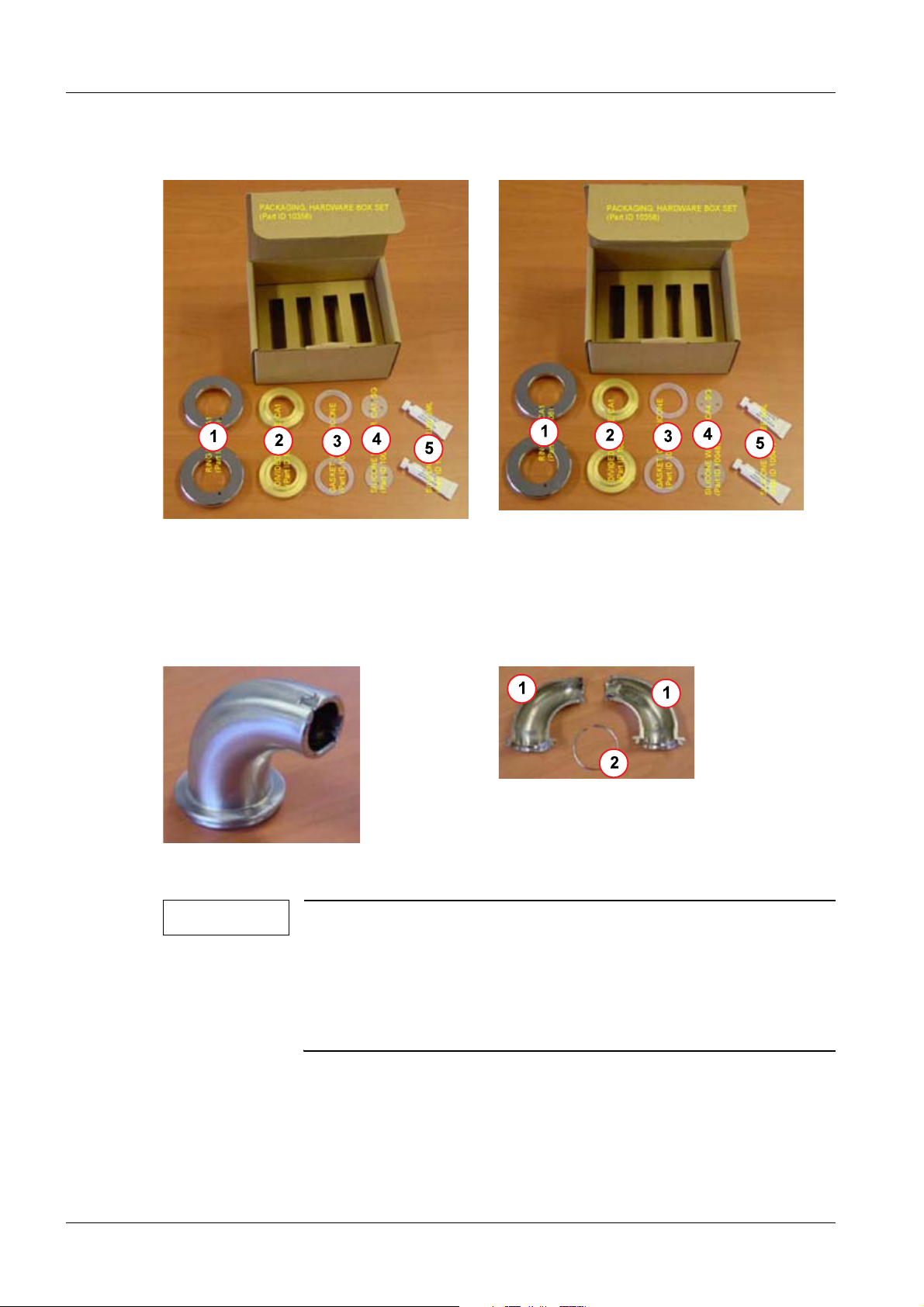
Items Included in Shipment 0
Fig. 1: Claymount accessory pack, 3-pole
Pos. 1 Mounting ring
Pos. 2 Contact ring
Pos. 3 Sealer ring
Pos. 4 Silicon disk, 3-pole
Pos. 5 Silicon oil
Fig. 3: Claymount angled cuff, complete
NOTE
When ordering a 3-pole high voltage cable, the 3-pole accessory
pack, an angled cuff as well as a 20 m Euroflex hose are included
in the shipment.
Fig. 2: Claymount accessory pack,
4-pole
Pos. 1 Mounting ring
Pos. 2 Contact ring
Pos. 3 Sealer ring
Pos. 4 Silicon disk, 4-pole
Pos. 5 Silicon oil
Fig. 4: Claymount angled cuff, single
parts
Pos. 1 Angled cuff half cowl
Pos. 2 Snap ring
When ordering a 4-pole high voltage cable, the 4-pole accessory
pack, an angled cuff as well as a 20 m Euroflex hose are included
in the shipment.
High Voltage Cables AX98-000.841.01.01.02 Siemens AG
09.05 CS PS 211
Page 8 of 38
Medical Solutions
Page 9
Claymount High Voltage Cables with Euroflex Hose 9
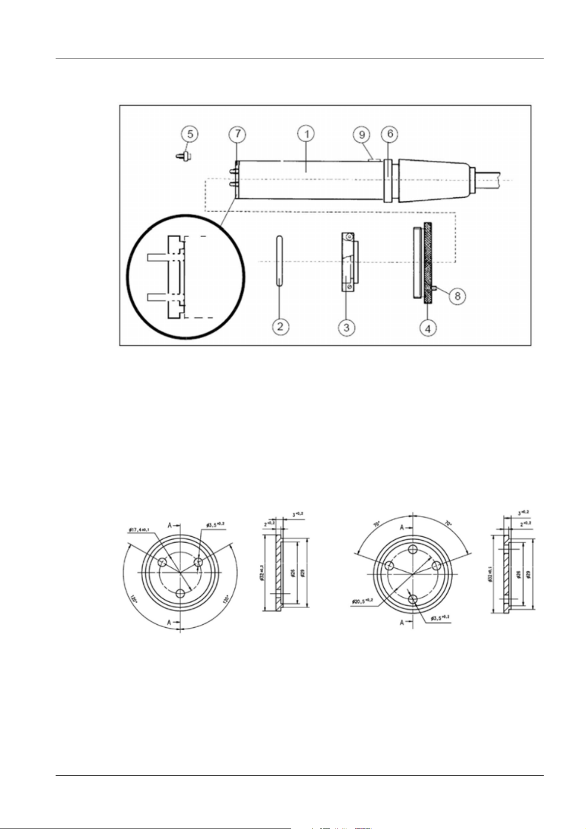
Connecting the High Voltage Connectors to the X-ray Tube Unit 0
Fig. 5: Claymount high voltage connectors
Pos. 1 High voltage connectors
Pos. 2 Sealer ring
Pos. 3 Contact ring
Pos. 4 Mounting ring
Pos. 5 Contact pin (replaceable
Pos. 6 Contact flange (part of the high voltage connector)
Pos. 7 Silicon disk
Pos. 8 Safety screw for mounting ring
Pos. 9 Guide nipple on high voltage connector
Fig. 6: Claymount silicon disk, Part No.:
10093772
Fig. 7: Claymount silicon disk, Part No.:
10093773
Siemens AG AX98-000.841.01.01.02 High Voltage Cables
Medical Solutions
09.05 CS PS 211
Page 9 of 38
Page 10
10 Claymount High Voltage Cables with Euroflex Hose
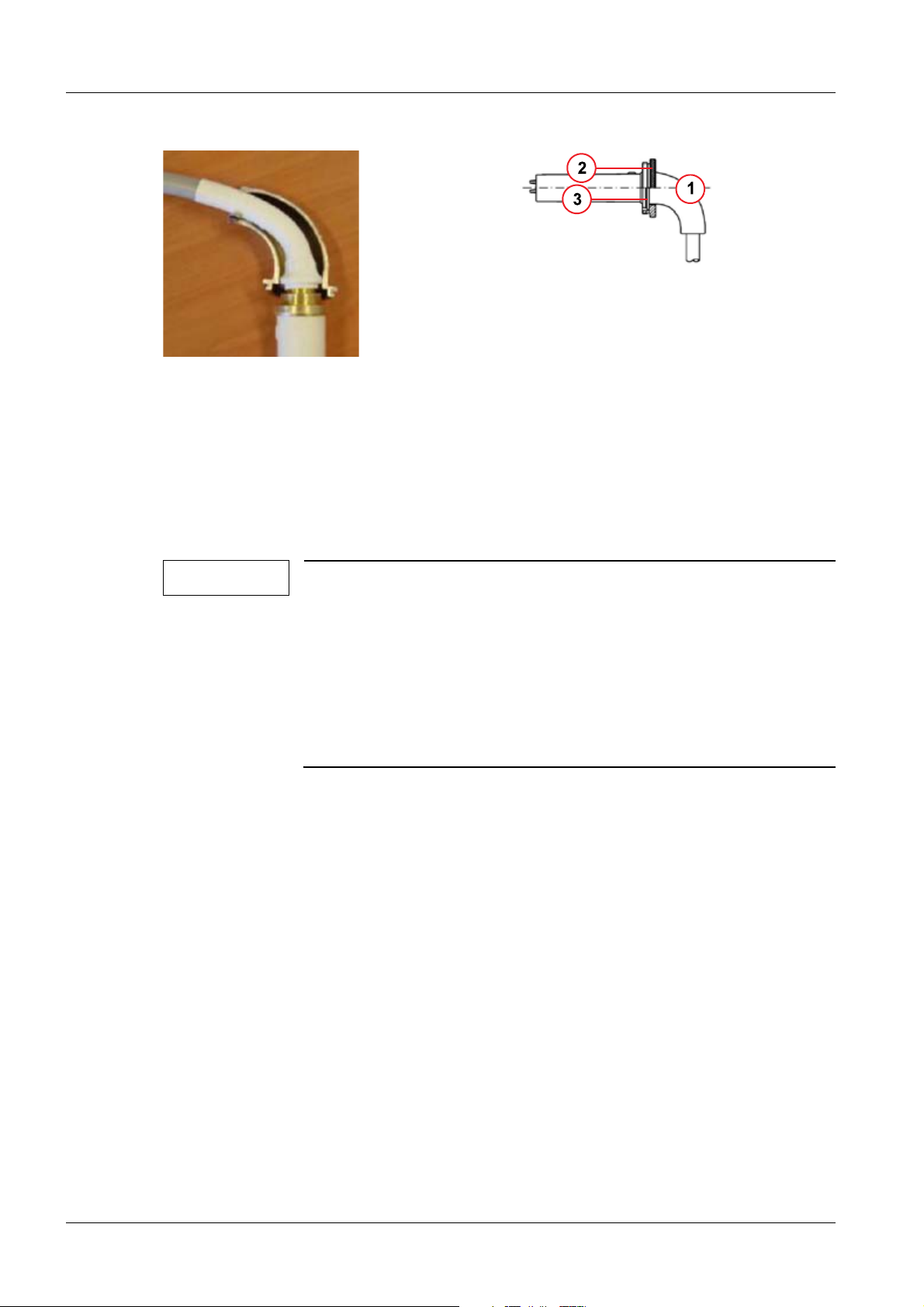
Fig. 9: Claymount angled cuff, installed
Pos. 1 Angled cuff half cowls
Pos. 2 Mounting ring
Pos. 3 Snap ring
Fig. 8: Claymount angled cuff, installation
• Turn out the safety screw (8/Fig.5/p.9) from the mounting ring until it is no longer pro-
jecting out on the inside of the mounting ring.
• Unscrew the parts of the contact ring (3/Fig.5/p.9).
• Slide the mounting ring (4/Fig.5/p.9) over the high voltage connector.
• Place the halves of the contact ring over the contact flange (6/Fig.5/p.9) and thread
them together.
NOTE
If the angled cuff (Fig.9/p.10) is installed, assembly of the con-
tact ring (3/Fig.5/p.9) is skipped.
• Remove the angled cuff by removing the snap ring
(2/Fig. 4 / p. 8).
• Place the two angled cuff half cowls on the contact flange of the
high voltage connector (Fig.8/p.10).
• Secure the two angled cuff half cowls with the snap ring
(3/Fig. 9 / p. 10).
• Slide the sealer ring (2/Fig.5/p.9) over the high voltage connector until it is up against
the contact ring.
• Evenly apply silicon oil using only the tip of the tube on the front of the connector. Then
place on the silicon disk (Fig.6/p.9) and moisten it with silicon oil.
High Voltage Cables AX98-000.841.01.01.02 Siemens AG
09.05 CS PS 211
Page 10 of 38
Medical Solutions
Page 11
Claymount High Voltage Cables with Euroflex Hose 11
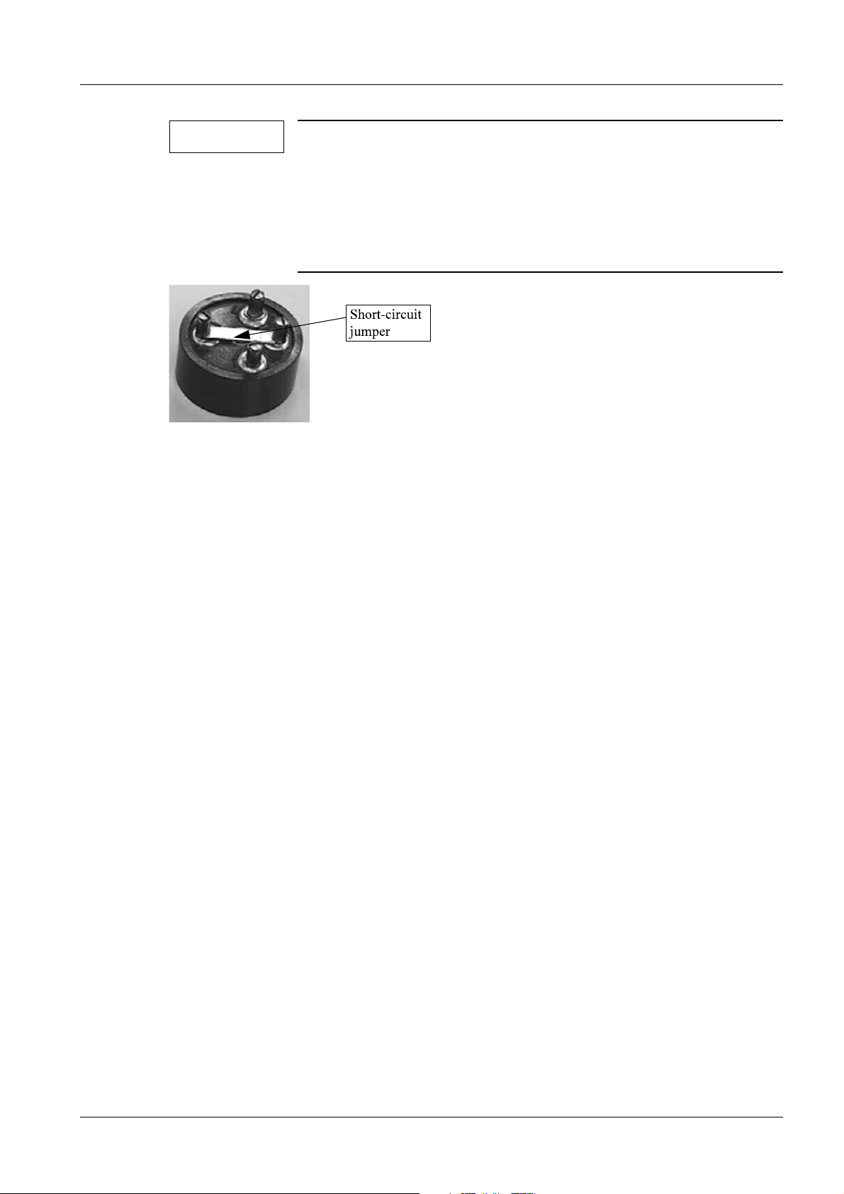
NOTE
For AXIOM Artis systems with a:
• MEGALIX CAT 125/35/80-121GW, Part No.: 5764506
• OPTITOP 150/40/80HC-100-4, Part No.: 4802216
there must be a short circuit jumper (Fig. 10 / p. 11) on the cathode
side high voltage cable between the grid (G) and cathode (0) connection pins.
Fig. 10: Short-circuit jumper for 2-focus tube
• Line up the guide nib on the high voltage connector with the slot on the socket and care-
fully insert the connector into the socket. When this is done, the air must be able to escape the socket.
• Hand-tighten the mounting ring on the cable sleeve.
• After about one hour, check the tightness of the mounting ring.
• Secure the mounting ring with the safety screw.
Connecting the High Voltage Connectors to the High Voltage Transformer 0
• Turn out the safety screw from the mounting ring until it is no longer projecting out on
the inside of the mounting ring.
• Unscrew the parts of the contact ring (3/Fig.5/p.9).
• Slide the mounting ring (4/Fig.5/p.9) over the high voltage connector.
• Place the halves of the contact ring over the contact flange (6/Fig.5/p.9) and thread
them together.
• Installation of the High Voltage Connector, depending on the Generator:
- With POLYDOROS IS A(F) open:
Check the oil level in the socket; if needed, add oil. Minimum oil level without the
connector inserted = 5 mm or 5 ml. The high voltage connector is inserted without a
silicon disk.
- With POLYDOROS A100:
Evenly apply silicon oil using only the tip of the tube on the front of the connector.
Then place on the silicon disk and moisten it with silicon oil.
• Line up the guide nib on the high voltage connector with the slot on the socket and care-
fully insert the connector into the socket.
• Hand-tighten the mounting ring.
• Secure the mounting ring with the safety screw.
Siemens AG AX98-000.841.01.01.02 High Voltage Cables
Medical Solutions
09.05 CS PS 211
Page 11 of 38
Page 12
12 Claymount High Voltage Cable, Locaflex, 3-pole
3Claymount High Voltage Cable, Locaflex, 3-pole
4-
Claymount High Voltage Cable, Model X2194 0
Part No.: Designation Use
30 65 500 HV Cable, 3-pole, 4mWith the following generators:
• POLYDOROS 80A
30 65 518 HV Cable, 3-pole,
6m
30 65 526 HV Cable, 3-pole,
8m
30 65 534 HV Cable, 3-pole,
10m
30 65 542 HV Cable, 3-pole,
12m
30 65 559 HV Cable, 3-pole,
14m
• POLYDOROS 100A
• POLYDOROS IS-A on workstation 1 with 3-pole
cathode-side high voltage cables
• POLYDOROS IS-AF on workstation 1 with
3-pole cathode-side high voltage cables
30 65 567 HV Cable, 3-pole,
16m
30 65 575 HV Cable, 3-pole,
18m
30 65 583 HV Cable, 3-pole,
20m
30 65 609 HV Cable, 3-pole,
24m
30 65 625 HV Cable, 3-pole,
28m
NOTE
If a 4-pole high voltage cable, model X2195 is used for connection
of grid-controlled or 3-focus X-ray tubes (4-pole cathode-side
socket) with the POLYDOROS IS-A(F), the 3-pole Superflex high
voltage cable, model X2199 must be used on the anode side.
Replacement: 0
Pirelli High Voltage Cables (Pirelli High Voltage Cables / p. 32)
NOTE
Anode-side and cathode-side high voltage cables must always be
from the same manufacturer. In other words, if a Claymount high
voltage cable is replaced with a Pirelli high voltage cable, both
high voltage cables have to be replaced.
High Voltage Cables AX98-000.841.01.01.02 Siemens AG
09.05 CS PS 211
Page 12 of 38
Medical Solutions
Page 13

Claymount High Voltage Cable, Locaflex, 3-pole 13
Recognition Features: 0
• High voltage cable color = cream white
• High voltage cables identified with the LOCAFLEX printing.
• Cable diameter of the high voltage cable = 16 mm
Items included in the Shipment: 0
When ordering a 3-pole high voltage cable, the 3-pole accessory pack is included.
Fig. 11: Claymount accessory pack, 3-pole
Pos. 1 Mounting ring
Pos. 2 Contact ring
Pos. 3 Sealer ring
Pos. 4 Silicon disk, 3-pole
Pos. 5 Silicon oil
Siemens AG AX98-000.841.01.01.02 High Voltage Cables
Medical Solutions
09.05 CS PS 211
Page 13 of 38
Page 14

14 Claymount High Voltage Cable, Locaflex, 3-pole
Connecting the High Voltage Connectors to the X-ray Tube Unit 0
Fig. 12: Claymount high voltage connectors
Pos. 1 High voltage connectors
Pos. 2 Sealer ring
Pos. 3 Contact ring
Pos. 4 Mounting ring
Pos. 5 Contact pin (replaceable
Pos. 6 Contact flange (part of the high voltage connector)
Pos. 7 Silicon disk
Pos. 8 Safety screw for mounting ring
Pos. 9 Guide nipple on high voltage connector
High Voltage Cables AX98-000.841.01.01.02 Siemens AG
09.05 CS PS 211
Page 14 of 38
Medical Solutions
Page 15

Claymount High Voltage Cable, Locaflex, 3-pole 15
Fig. 13: Claymount contact pin, old
Fig. 15: Claymount contact pin, new
Fig. 14: Claymount silicon disk, Part No.:
3065872
Fig. 16: Claymount silicon disk, Part No.:
10093772
• Turn out the safety screw (8/Fig. 12 / p. 14) from the mounting ring until it is no longer
projecting out on the inside of the mounting ring.
• Unscrew the parts of the contact ring (3/Fig. 12 / p. 14).
• Slide the mounting ring (4/Fig. 12 / p. 14) over the high voltage connector.
• Place the halves of the contact ring over the contact flange (6/Fig. 12 / p. 14) and
thread them together.
• Slide the sealer ring (2/Fig. 12 / p. 14) over the high voltage connector until it is up
against the contact ring.
• Evenly apply silicon oil using only the tip of the tube on the front of the connector. Then
place on the silicon disk and moisten it with silicon oil.
NOTE
Two types of contact pins are used in the Claymount high voltage
cables:
• With the cone-shaped, bronze-colored contact pin
(Fig. 13 / p. 15), the silicon disk with Part No.: 3065872
(Fig. 14 / p. 15) is used
• With the straight, silver-colored contact pin (Fig. 15 / p. 15), the
silicon disk with Part No.: 10093772 (Fig. 16 / p. 15) is used
Siemens AG AX98-000.841.01.01.02 High Voltage Cables
Medical Solutions
09.05 CS PS 211
Page 15 of 38
Page 16

16 Claymount High Voltage Cable, Locaflex, 3-pole
• Line up the guide nib on the high voltage connector with the slot on the socket and care-
fully insert the connector into the socket. When this is done, the air must be able to escape the socket.
• Hand-tighten the mounting ring on the cable sleeve.
• After about one hour, check the tightness of the mounting ring.
• Secure the mounting ring with the safety screw.
Connecting the High Voltage Connectors to the High Voltage Transformer 0
• Turn out the safety screw from the mounting ring until it is no longer projecting out on
the inside of the mounting ring.
• Unscrew the parts of the contact ring (3/Fig. 12 / p. 14).
• Slide the mounting ring (4/Fig. 12 / p. 14) over the high voltage connector.
• Place the halves of the contact ring over the contact flange (6/Fig. 12 / p. 14) and
thread them together.
• Check the oil level in the socket; if needed, add oil. Minimum oil level without the con-
nector inserted = 5 mm or 5 ml. The high voltage connector is inserted without a silicon
disk.
• Line up the guide nib on the high voltage connector with the slot on the socket and care-
fully insert the connector into the socket.
• Hand-tighten the mounting ring.
• Secure the mounting ring with the safety screw.
High Voltage Cables AX98-000.841.01.01.02 Siemens AG
09.05 CS PS 211
Page 16 of 38
Medical Solutions
Page 17

Claymount High Voltage Cable, Superflex, 3-pole 17
4Claymount High Voltage Cable, Superflex, 3- pole
5-
High Voltage Cables, Model X2195 0
Part No.: Designation Use
30 65 807 HV Cable, 3-pole,
24m
30 65 815 HV Cable, 3-pole,
26m
30 65 823 HV Cable, 3-pole,
28m
NOTE
If a 4-pole high voltage cable, model X2195 is used for connection
of grid-controlled or 3-focus X-ray tubes (4-pole cathode-side
socket) with the POLYDOROS IS-A(F) / IS-C(F), the 3-pole Superflex high voltage cable, model X2199 must be used on the anode
side.
With the following generators:
• POLYDOROS IS-C
• POLYDOROS IS-CF
• POLYDOROS IS-A on workstation 2 with 4-pole
cathode-side high voltage cables
• POLYDOROS IS-AF on workstation 2 with 4-pole
cathode-side high voltage cables
Replacement: 0
Pirelli High Voltage Cables (Pirelli High Voltage Cables / p. 32)
NOTE
Anode-side and cathode-side high voltage cables must always be
from the same manufacturer. In other words, if a Claymount high
voltage cable is replaced with a Pirelli high voltage cable, both
high voltage cables have to be replaced.
Recognition Features: 0
• High voltage cable color = cream white
• Cable diameter of the high voltage cable = 16 mm
Items included in the Shipment: 0
When ordering a 3-pole high voltage cable, the 3-pole accessory pack is included.
Siemens AG AX98-000.841.01.01.02 High Voltage Cables
Medical Solutions
09.05 CS PS 211
Page 17 of 38
Page 18

18 Claymount High Voltage Cable, Superflex, 3-pole
Fig. 17: Claymount accessory pack, 3-pole
Pos. 1 Mounting ring
Pos. 2 Contact ring
Pos. 3 Sealer ring
Pos. 4 Silicon disk, 3-pole
Pos. 5 Silicon oil
High Voltage Cables AX98-000.841.01.01.02 Siemens AG
09.05 CS PS 211
Page 18 of 38
Medical Solutions
Page 19

Claymount High Voltage Cable, Superflex, 3-pole 19
Connecting the High Voltage Connectors to the X-ray Tube Unit 0
Fig. 18: Claymount high voltage connectors
Pos. 1 High voltage connectors
Pos. 2 Sealer ring
Pos. 3 Contact ring
Pos. 4 Mounting ring
Pos. 5 Contact pin (replaceable
Pos. 6 Contact flange (part of the high voltage connector)
Pos. 7 Silicon disk
Pos. 8 Safety screw for mounting ring
Pos. 9 Guide nipple on high voltage connector
Siemens AG AX98-000.841.01.01.02 High Voltage Cables
Medical Solutions
09.05 CS PS 211
Page 19 of 38
Page 20

20 Claymount High Voltage Cable, Superflex, 3-pole
Fig. 19: Claymount contact pin, old
Fig. 21: Claymount contact pin, new
Fig. 20: Claymount silicon disk, Part No.:
3065872
Fig. 22: Claymount silicon disk, Part No.:
10093772
• Turn out the safety screw (8/Fig. 18 / p. 19) from the mounting ring until it is no longer
projecting out on the inside of the mounting ring.
• Unscrew the parts of the contact ring (3/Fig. 18 / p. 19).
• Slide the mounting ring (4/Fig. 18 / p. 19) over the high voltage connector.
• Place the halves of the contact ring over the contact flange (6/Fig. 18 / p. 19) and
thread them together.
• Slide the sealer ring (2/Fig. 18 / p. 19) over the high voltage connector until it is up
against the contact ring.
• Evenly apply silicon oil using only the tip of the tube on the front of the connector. Then
place on the silicon disk and moisten it with silicon oil.
NOTE
Two types of contact pins are used in the Claymount high voltage
cables:
• With the cone-shaped, bronze-colored contact pin
(Fig. 19 / p. 20), the silicon disk with Part No.: 3065872
(Fig. 20 / p. 20) is used
• With the straight, silver-colored contact pin (Fig. 21 / p. 20), the
silicon disk with Part No.: 10093772 (Fig. 22 / p. 20) is used
High Voltage Cables AX98-000.841.01.01.02 Siemens AG
09.05 CS PS 211
Page 20 of 38
Medical Solutions
Page 21

Claymount High Voltage Cable, Superflex, 3-pole 21
• Line up the guide nib on the high voltage connector with the slot on the socket and care-
fully insert the connector into the socket. When this is done, the air must be able to escape the socket.
• Hand-tighten the mounting ring on the cable sleeve.
• After about one hour, check the tightness of the mounting ring.
• Secure the mounting ring with the safety screw.
Connecting the High Voltage Connectors to the High Voltage Transformer 0
• Turn out the safety screw from the mounting ring until it is no longer projecting out on
the inside of the mounting ring.
• Unscrew the parts of the contact ring (3/Fig. 18 / p. 19).
• Slide the mounting ring (4/Fig. 18 / p. 19) over the high voltage connector.
• Place the halves of the contact ring over the contact flange (6/Fig. 18 / p. 19) and
thread them together.
• Check the oil level in the socket; if needed, add oil. Minimum oil level without the con-
nector inserted = 5 mm or 5 ml. The high voltage connector is inserted without a silicon
disk.
• Line up the guide nib on the high voltage connector with the slot on the socket and care-
fully insert the connector into the socket.
• Hand-tighten the mounting ring.
• Secure the mounting ring with the safety screw.
Siemens AG AX98-000.841.01.01.02 High Voltage Cables
Medical Solutions
09.05 CS PS 211
Page 21 of 38
Page 22

22 Claymount High Voltage Cable, Superflex, 4-pole
5Claymount High Voltage Cable, Superflex, 4-pole
6-
High Voltage Cables, Model X2199 0
Part No.: Designation Use
30 65 658 HV Cable, 4-pole, 6mWith the following generators:
• POLYDOROS IS-C
30 65 666 HV Cable, 4-pole,
8m
30 65 674 HV Cable, 4-pole,
10m
30 65 682 HV Cable, 4-pole,
12m
• POLYDOROS IS-CF
• POLYDOROS IS-A on workstation 2 with 4-pole
cathode-side high voltage cables
• POLYDOROS IS-AF on workstation 2 with 4-pole
cathode-side high voltage cables
• POLYDOROS 80A with 3-focus X-ray tubes
30 65 690 HV Cable, 4-pole,
14m
30 65 708 HV Cable, 4-pole,
16m
30 65 724 HV Cable, 4-pole,
20m
30 65 740 HV Cable, 4-pole,
24m
30 65 757 HV Cable, 4-pole,
26m
30 65 765 HV Cable, 4-pole,
28m
NOTE
If a 4-pole high voltage cable, model X2195 is used for connection
of grid-controlled or 3-focus X-ray tubes (4-pole cathode-side
socket) with the POLYDOROS IS-A(F) / IS-C(F), the 3-pole Superflex high voltage cable, model X2199 must be used on the anode
side.
• POLYDOROS 100A with 3-focus X-ray tubes
Replacement: 0
Pirelli High Voltage Cables (Pirelli High Voltage Cables / p. 32)
NOTE
High Voltage Cables AX98-000.841.01.01.02 Siemens AG
Anode-side and cathode-side high voltage cables must always be
from the same manufacturer. In other words, if a Claymount high
voltage cable is replaced with a Pirelli high voltage cable, both
high voltage cables have to be replaced.
09.05 CS PS 211
Page 22 of 38
Medical Solutions
Page 23

Claymount High Voltage Cable, Superflex, 4-pole 23
Recognition Features: 0
• High voltage cable color = cream white
• Cable diameter of the high voltage cable = 19mm
Items included in the Shipment: 0
When ordering a 4-pole high voltage cable, the 4-pole accessory pack is included.
Fig. 23: Claymount accessory pack, 4-pole
Pos. 1 Mounting ring
Pos. 2 Contact ring
Pos. 3 Sealer ring
Pos. 4 Silicon disk, 4-pole
Pos. 5 Silicon oil
Siemens AG AX98-000.841.01.01.02 High Voltage Cables
Medical Solutions
09.05 CS PS 211
Page 23 of 38
Page 24

24 Claymount High Voltage Cable, Superflex, 4-pole
Connecting the High Voltage Connectors to the X-ray Tube Unit 0
Fig. 24: Claymount high voltage connectors
Pos. 1 High voltage connectors
Pos. 2 Sealer ring
Pos. 3 Contact ring
Pos. 4 Mounting ring
Pos. 5 Contact pin (replaceable
Pos. 6 Contact flange (part of the high voltage connector)
Pos. 7 Silicon disk
Pos. 8 Safety screw for mounting ring
Pos. 9 Guide nipple on high voltage connector
High Voltage Cables AX98-000.841.01.01.02 Siemens AG
09.05 CS PS 211
Page 24 of 38
Medical Solutions
Page 25

Claymount High Voltage Cable, Superflex, 4-pole 25
Fig. 25: Claymount contact pin, old
Fig. 27: Claymount contact pin, new
Fig. 26: Claymount silicon disk, Part No.:
4775065
Fig. 28: Claymount silicon disk, Part No.:
10093773
• Turn out the safety screw (8/Fig. 24 / p. 24) from the mounting ring until it is no longer
projecting out on the inside of the mounting ring.
• Unscrew the parts of the contact ring (3/Fig. 24 / p. 24).
• Slide the mounting ring (4/Fig. 24 / p. 24) over the high voltage connector.
• Place the halves of the contact ring over the contact flange (6/Fig. 24 / p. 24) and
thread them together.
• Slide the sealer ring (2/Fig. 24 / p. 24) over the high voltage connector until it is up
against the contact ring.
• Evenly apply silicon oil using only the tip of the tube on the front of the connector. Then
place on the silicon disk and moisten it with silicon oil.
NOTE
Two types of contact pins are used in the Claymount high voltage
cables:
• With the cone-shaped, bronze-colored contact pin
(Fig. 25 / p. 25), the silicon disk with Part No.: 3065872
(Fig. 20 / p. 20) is used
• With the straight, silver-colored contact pin (Fig. 27 / p. 25), the
silicon disk with Part No.: 10093772 (Fig. 22 / p. 20) is used
Siemens AG AX98-000.841.01.01.02 High Voltage Cables
Medical Solutions
09.05 CS PS 211
Page 25 of 38
Page 26

26 Claymount High Voltage Cable, Superflex, 4-pole
• Line up the guide nib on the high voltage connector with the slot on the socket and care-
fully insert the connector into the socket. When this is done, the air must be able to escape the socket.
• Hand-tighten the mounting ring on the cable sleeve.
• After about one hour, check the tightness of the mounting ring.
• Secure the mounting ring with the safety screw.
Connecting the High Voltage Connectors to the High Voltage Transformer 0
• Turn out the safety screw from the mounting ring until it is no longer projecting out on
the inside of the mounting ring.
• Unscrew the parts of the contact ring (3/Fig. 24 / p. 24).
• Slide the mounting ring (4/Fig. 24 / p. 24) over the high voltage connector.
• Place the halves of the contact ring over the contact flange (6/Fig. 24 / p. 24) and
thread them together.
• Check the oil level in the socket; if needed, add oil. Minimum oil level without the con-
nector inserted = 5 mm or 5 ml. The high voltage connector is inserted without a silicon
disk.
• Line up the guide nib on the high voltage connector with the slot on the socket and care-
fully insert the connector into the socket.
• Hand-tighten the mounting ring.
• Secure the mounting ring with the safety screw.
High Voltage Cables AX98-000.841.01.01.02 Siemens AG
09.05 CS PS 211
Page 26 of 38
Medical Solutions
Page 27

Pirelli High Voltage Cables with Euroflex Hose 27
6Pirelli High Voltage Cables with Euroflex Hose
7-
High Voltage Cables, Model G141E / G145E 0
Part No.: Designation Use
65 89 506 HV Cable, 3-pole,
AXIOM Artis MP / dMP
20m
65 89 514 HV Cable, 4-pole,
AXIOM Artis MP / dMP
20m
65 55 978 HV Cable, 3-pole,
28m
AXIOM Artis FA / FC / dFA / dFC / dFCM / BA
(Plane A) / BC (Plane A) / dBA (Plane A) / dBC
(Plane A)
65 55 986 HV Cable, 4-pole,
28m
AXIOM Artis FA / FC / dFA / dFC / dFCM / BA
(Plane A) / BC (Plane A) / dBA (Plane A) / dBC
(Plane A)
65 89 639 HV Cable, 3-pole,
30m
65 89 647 HV Cable, 4-pole,
30m
AXIOM Artis TA / TC / dTA / dTC / BA (Plane B) /
BC (Plane B) / dBA (Plane B) / dBC (Plane B)
AXIOM Artis TA / TC / dTA / dTC / BA (Plane B) /
BC (Plane B) / dBA (Plane B) / dBC (Plane B)
Replacement: 0
Claymount High Voltage Cables with Euroflex Hose (Claymount High Voltage Cables with
Euroflex Hose / p. 7)
NOTE
Mixed use of anode-side and cathode-side high voltage cables is
permitted. In other words, if a Pirelli high voltage cable is replaced
with a Claymount high voltage cable, both high voltage cables do
not have to be replaced.
Recognition Features: 0
• Color of the high voltage cable connectors = blue or black
• High voltage cables identified with the SIEMENS printing.
• Cable diameter of the 3- and 4-pole high voltage cables = 16 mm
• High Voltage Cables covered with the black Euroflex hose
Siemens AG AX98-000.841.01.01.02 High Voltage Cables
Medical Solutions
09.05 CS PS 211
Page 27 of 38
Page 28

28 Pirelli High Voltage Cables with Euroflex Hose
Items Included in Shipment 0
Fig. 29: Pirelli accessory pack, 3-pole
Pos. 1 Mounting ring
Pos. 2 Set screws
Pos. 3 Contact ring
Pos. 4 Sealer ring
Pos. 5 Silicon disk, 3-pole
Pos. 6 Silicon oil
NOTE
When ordering a 3-pole high voltage cable, two 3-pole accessory
packs are included.
When ordering a 4-pole high voltage cable, two 4-pole accessory
packs are included.
Fig. 30: Pirelli accessory pack,
4-pole
Pos. 1 Mounting ring
Pos. 2 Set screws
Pos. 3 Contact ring
Pos. 4 Sealer ring
Pos. 5 Silicon disk, 4-pole
Pos. 6 Silicon oil
High Voltage Cables AX98-000.841.01.01.02 Siemens AG
09.05 CS PS 211
Page 28 of 38
Medical Solutions
Page 29

Pirelli High Voltage Cables with Euroflex Hose 29
Connecting the High Voltage Connectors to the X-ray Tube Unit 0
Fig. 31: Pirelli high voltage connectors, installation
Pos. 1 Mounting ring
Pos. 2 Contact ring
Pos. 3 Sealer ring
Pos. 4 Silicon disk
Pos. 5 Guide nipple on high voltage connector
Fig. 33: Pirelli silicon disk, Part No.:
Fig. 32: Pirelli silicon disk, Part No.: 1786508
1786516
• Turn out the two safety screws (2/Fig. 29 / p. 28) from the mounting ring until they are
no longer projecting out on the inside of the mounting ring.
• Slide the mounting ring (1/Fig. 31 / p. 29) over the connector, threads facing the con-
nector.
• Place the contact ring half cowls (2/Fig. 31 / p. 29) over the flange with the slot close to
stop.
• Evenly tighten the screws on the contact ring half cowls.
Siemens AG AX98-000.841.01.01.02 High Voltage Cables
Medical Solutions
09.05 CS PS 211
Page 29 of 38
Page 30

30 Pirelli High Voltage Cables with Euroflex Hose
• Pull the sealer ring (3/Fig. 31 / p. 29) over the connector up to the flange.
• Evenly apply silicon oil using only the tip of the tube on the front of the connector. Then
place on the silicon disk (4/Fig. 31 / p. 29) and moisten it with silicon oil.
NOTE
For AXIOM Artis systems with a:
• MEGALIX CAT 125/35/80-121GW, Part No.: 5764506
• OPTITOP 150/40/80HC-100-4, Part No.: 4802216
there must be a short circuit jumper (Fig. 34 / p. 30) on the cathode
side high voltage cable between the grid (G) and cathode (0) connection pins.
Fig. 34: Short-circuit jumper for 2-focus tube
• Line up the guide nib on the high voltage connector (5/Fig. 31 / p. 29) with the slot on
the socket and carefully insert the connector into the socket.
• Hand-tighten the mounting ring; when doing this, hold the high voltage cable so it does
not twist.
• Tighten both set screws on the mounting ring until there is slight resistance (securing
against turning).
Connecting the High Voltage Connectors to the High Voltage Transformer 0
• Turn out the two safety screws (2/Fig. 29 / p. 28) from the mounting ring until they are
no longer projecting out on the inside of the mounting ring.
• Slide the mounting ring (1/Fig. 31 / p. 29) over the connector, threads facing the con-
nector.
• Place the contact ring half cowls (2/Fig. 31 / p. 29) over the flange with the slot close to
stop.
• Evenly tighten the screws on the contact ring half cowls.
• Installation of the High Voltage Connector, depending on the Generator:
- With POLYDOROS A100:
Evenly apply silicon oil using only the tip of the tube on the front of the connector.
Then place on the silicon disk and moisten it with silicon oil.
- With POLYDOROS IS A(F) open:
Check the oil level in the socket; if needed, add oil. Minimum oil level without the
connector inserted = 5 mm or 5 ml. The high voltage connector is inserted without a
silicon disk.
High Voltage Cables AX98-000.841.01.01.02 Siemens AG
09.05 CS PS 211
Page 30 of 38
Medical Solutions
Page 31

Pirelli High Voltage Cables with Euroflex Hose 31
• Line up the guide nib on the high voltage connector (5/Fig. 31 / p. 29) with the slot on
the socket and carefully insert the connector into the socket.
• Hand-tighten the mounting ring; when doing this, hold the high voltage cable so it does
not twist.
• Tighten both set screws on the mounting ring until there is slight resistance (securing
against turning).
Siemens AG AX98-000.841.01.01.02 High Voltage Cables
Medical Solutions
09.05 CS PS 211
Page 31 of 38
Page 32

32 Pirelli High Voltage Cables
7Pirelli High Voltage Cables
8-
High Voltage Cables, Model RH098 0
Part No.: Designation Use
44 66 389 HV Cable, 3-pole, 4mWith the following generators:
• POLYDOROS 80A
44 66 397 HV Cable, 3-pole,
6m
44 66 405 HV Cable, 3-pole,
8m
44 66 413 HV Cable, 3-pole,
10m
44 66 421 HV Cable, 3-pole,
12m
44 66 439 HV Cable, 3-pole,
14m
44 66 447 HV Cable, 3-pole,
16m
• POLYDOROS 100A
• POLYDOROS IS-A
• POLYDOROS IS-AF
• POLYDOROS IS-C
• POLYDOROS IS-CF
• POLYDOROS SX50/80
• POLYDOROS SX65/80
• POLYDOROS LX30/50
• POLYDOROS LX30/50 Lite
• POLYDOROS LX 80
• POLYDOROS IT
44 66 454 HV Cable, 3-pole,
18m
44 66 462 HV Cable, 3-pole,
20m
44 66 470 HV Cable, 3-pole,
22m
44 66 488 HV Cable, 3-pole,
24m
44 66 496 HV Cable, 3-pole,
26m
58 90 194 HV Cable, 3-pole,
28m
58 90 186 HV Cable, 3-pole,
30m
High Voltage Cables AX98-000.841.01.01.02 Siemens AG
09.05 CS PS 211
Page 32 of 38
Medical Solutions
Page 33

Pirelli High Voltage Cables 33
Part No.: Designation Use
58 90 160 HV Cable, 4-pole,
16m
58 90 152 HV Cable, 4-pole,
20m
58 90 145 HV Cable, 4-pole,
24m
58 90 137 HV Cable, 4-pole,
26m
58 90 129 HV Cable, 4-pole,
28m
58 90 103 HV Cable, 4-pole,
30m
NOTE
When used with the POLYDOROS IS-A(F) / IS-C(F), the D45 board
(Part No.: 2797962) must have Rev. 02 or higher. This is necessary
to ensure adaptation of the capacitance to the high voltage cable
Model RH098.
With the following generators:
• POLYDOROS IS-C and IS-CF
• POLYDOROS IS-A and IS-AF on workstation 2 with
4-pole cathode-side high voltage cables
• POLYDOROS 80A and 100A with 3-focus X-ray
tubes
Replacement: 0
n.a.
Recognition Features: 0
• Color of the high voltage cable connectors = blue or black
• High voltage cables identified with the SIEMENS printing.
• Cable diameter of the 3- and 4-pole high voltage cables = 16 mm
Siemens AG AX98-000.841.01.01.02 High Voltage Cables
Medical Solutions
09.05 CS PS 211
Page 33 of 38
Page 34

34 Pirelli High Voltage Cables
Items Included in Shipment 0
Fig. 35: Pirelli accessory pack, 3-pole
Pos. 1 Mounting ring
Pos. 2 Set screws
Pos. 3 Contact ring
Pos. 4 Sealer ring
Pos. 5 Silicon disk, 3-pole
Pos. 6 Silicon oil
NOTE
When ordering a 3-pole high voltage cable, two 3-pole accessory
packs are included.
When ordering a 4-pole high voltage cable, two 4-pole accessory
packs are included.
Fig. 36: Pirelli accessory pack,
4-pole
Pos. 1 Mounting ring
Pos. 2 Set screws
Pos. 3 Contact ring
Pos. 4 Sealer ring
Pos. 5 Silicon disk, 4-pole
Pos. 6 Silicon oil
High Voltage Cables AX98-000.841.01.01.02 Siemens AG
09.05 CS PS 211
Page 34 of 38
Medical Solutions
Page 35

Pirelli High Voltage Cables 35
Connecting the High Voltage Connectors to the X-ray Tube Unit 0
Fig. 37: Pirelli high voltage connectors, installation
Pos. 1 Mounting ring
Pos. 2 Contact ring
Pos. 3 Sealer ring
Pos. 4 Silicon disk
Pos. 5 Guide nipple on high voltage connector
Fig. 39: Pirelli silicon disk, Part No.:
Fig. 38: Pirelli silicon disk, Part No.: 1786508
1786516
• Turn out the two safety screws (2/Fig. 35 / p. 34) from the mounting ring until they are
no longer projecting out on the inside of the mounting ring.
• Slide the mounting ring (1/Fig. 37 / p. 35) over the connector, threads facing the con-
nector.
• Place the contact ring half cowls (2/Fig. 37 / p. 35) over the flange with the slot close to
stop.
• Evenly tighten the screws on the contact ring half cowls.
Siemens AG AX98-000.841.01.01.02 High Voltage Cables
Medical Solutions
09.05 CS PS 211
Page 35 of 38
Page 36

36 Pirelli High Voltage Cables
• Pull the sealer ring (3/Fig. 37 / p. 35) over the connector up to the flange.
• Evenly apply silicon oil using only the tip of the tube on the front of the connector. Then
place on the silicon disk (4/Fig. 37 / p. 35) and moisten it with silicon oil.
• Line up the guide nib on the high voltage connector (5/Fig. 37 / p. 35) with the slot on
the socket and carefully insert the connector into the socket.
• Hand-tighten the mounting ring; when doing this, hold the high voltage cable so it does
not twist.
• Tighten both set screws on the mounting ring until there is slight resistance (securing
against turning).
Connecting the High Voltage Connectors to the High Voltage Transformer 0
• Turn out the two safety screws (2/Fig. 35 / p. 34) from the mounting ring until they are
no longer projecting out on the inside of the mounting ring.
• Slide the mounting ring (1/Fig. 37 / p. 35) over the connector, threads facing the con-
nector.
• Place the contact ring half cowls (2/Fig. 37 / p. 35) over the flange with the slot close to
stop.
• Evenly tighten the screws on the contact ring half cowls.
• Installation of the High Voltage Connector, depending on the Generator:
- With POLYDOROS IT:
Evenly apply silicon oil using only the tip of the tube on the front of the connector.
Then place on the silicon disk and moisten it with silicon oil.
- With all other generators:
Check the oil level in the socket; if needed, add oil. Minimum oil level without the
connector inserted = 5 mm or 5 ml. The high voltage connector is inserted without a
silicon disk.
• Line up the guide nib on the high voltage connector (5/Fig. 37 / p. 35) with the slot on
the socket and carefully insert the connector into the socket.
• Hand-tighten the mounting ring; when doing this, hold the high voltage cable so it does
not twist.
• Tighten both set screws on the mounting ring until there is slight resistance (securing
against turning).
High Voltage Cables AX98-000.841.01.01.02 Siemens AG
09.05 CS PS 211
Page 36 of 38
Medical Solutions
Page 37

Changes to Previous Version 37
8Changes to Previous Version
9-
None; initial publication.
Siemens AG AX98-000.841.01.01.02 High Voltage Cables
Medical Solutions
09.05 CS PS 211
Page 37 of 38
Page 38

38 Changes to Previous Version
High Voltage Cables AX98-000.841.01.01.02 Siemens AG
09.05 CS PS 211
Page 38 of 38
Medical Solutions
 Loading...