

Siemens GBB163.1U, GBB164.1U, GBB161.1P, GBB166.1U, GBB163.1P Technical Instructions
...
Technical Instructions
June 22, 2015
Electronic Damper Actuators
Non-Spring Return, 24 Vac, Modulating Control
set
Dual Auxiliary
221 lb-in
Standard
GBB161.1U
GBB163.1U
GBB164.1U
GBB166.1U
Plenum Cable
GBB161.1P
GBB163.1P
GBB164.1P
GBB166.1P
310 lb-in
Standard
GIB161.1U
GIB163.1U
GIB164.1U
GIB166.1U
Plenum Cable
GIB161.1P
GIB163.1P
GIB164.1P
GIB166.1P
OpenAir™ GBB/GIB Series
Document No. 155-176P25
EA GBB/GIB-1
Description
Features
The OpenAir, non-spring return (NSR), 24 Vac, rotary, direct-coupled, electric actuator
is designed for modulating control of building HVAC dampers.
• Built-in feedback on modulating units
• Unique self-centering shaft coupling
• All metal housing
• Two torque ranges available
• Manual override
• Offset and span adjustment models available
• Independently adjustable dual auxiliary switches available
• UL, cUL and CE listed
Product Numbers Table 1.
24 Vac Operating Voltage
Input
Torque
(25 Nm)
Signal Cabling Standard
0 to 10 Vdc
Span/Off
Adjustable
Dual Auxiliary
Switches and
Span/Offset
Adjustable
Switches only
(35 Nm)
Application
0 to 10 Vdc
These actuators are used in constant or variable air volume installations for the control of supply
return air, mixed air, exhaust, rooftop units, and face and bypass dampers requiring up to 221 lb-in
(25 Nm) torque or 310 lb-in (35 Nm) torque.
Siemens Industry, Inc.
Technical Instructions GBB/GIB Series Non-spring Return, 24 Vac, Modulating Control
WARNING:
CAUTION:
Operating voltage (G–G0) 24 Vac ±20%
of two actuators
Input signal (Y–G0)
Position output signal (U–G0)
Operating voltage, input signal and Class 2, in accordance with UL/CSA
Dual auxiliary switches
Document Number 155-176P25
June 22, 2015
Warning/Caution Notations
Personal injury/loss of life may occur if you do perform a procedure as
specified.
Equipment damage or loss of data may occur if you do not perform a
procedure as specified.
Specifications
Power supply
Control Signal
Feedback Signal
Equipment Rating
Auxiliary Features
Frequency 50/60 Hz
Power consumption
Running… 8 VA, 8W
Holding… 1.1W
For one tandem application 12 VA
voltage-input 0 to 10 Vdc
Input resistance >100K ohms
Voltage-output 0 to 10 Vdc
Maximum output current DC 1 mA
position output signal
Plenum type actuators as a whole device Class 2, in accordance with UL/CSA
AC rating (standard cable) 24 to 250 Vac
AC 6A resistive
AC 2A general purpose
AC rating (Plenum cable) 24 Vac
AC 4A resistive
AC 2A general purpose
DC rating (Standard/Plenum cable) 12 to 30 Vdc
DC 2A
Switch Range
Switch A 0 to 90° with 5° intervals
Recommended range usage 0 to 45°
Factory setting 5°
Switch B 0 to 90° with 5° intervals
Recommended range usage 45 to 90°
Factory setting 85°
Switching hysteresis 2°
Page 2 Siemens Industry, Inc.
WARNING:
Apply only AC-line voltage from the same phase or only UL-Class 2 voltage (SELV
for CE conformance) to the switching outputs of both auxiliary switches A and B.
Mixed operation is not permissible.
NOTE: With plenum cables, only UL-Class 2 voltage (SELV for CE is
permissible).

GBB/GIB Series Non-spring Return, 24 Vac, Modulating Control Technical Instructions
Torque
Shaft size 3/8 to 1-inch (8 to 25.6 mm) diameter
Enclosure NEMA 2 in vertical position to 90°
Ambient temperature
UL listed to UL873
Pre-cabled connection 18 AWG
Document Number 155-176P25
June 22, 2015
Specifications,
Continued
Function
Mounting
Housing
Ambient Conditions
GBB… 221 lb-in (25 Nm)
GIB… 310 lb-in (35 Nm)
Runtime for 90° opening or closing 125 seconds at 60 Hz
150 seconds at 50 Hz
Nominal angle of rotation 90°
Maximum angular rotation 95°
Noise level <45 dBA
1/4 to 5/8-inch (6 to 18 mm) square
Minimum shaft length 3/4-inches (20 mm)
to the left and right of vertical
See Figure 18
NEMA 3R rated when installed with
ASK75.1U Weather Shield in the
vertical position. See Accessories.
IP54 according to EN60529
Material Die cast aluminum alloy
Gear lubrication Silicone-free
Operation -25°F to 130°F (-32°C to 55°C)
Storage and transport -40°F to 158°F (-40°C to 70°C)
Ambient humidity (non-condensing) 95% rh
Agency Approvals
cUL certified to Canadian Standard
C22.2 No. 24-93
CE conformity:
Low-voltage directive 2006/95/EC
Miscellaneous
Cable length 3 feet (0.9m)
Life cycle Designed for over 60,000 full strokes
and a minimum of 1.5 million
repositions at rated torque and
temperature
Dimensions See Figure 30
Weight 4.4 lbs (2 kg)
Country of Origin USA
Electromagnetic compatibility 2004/108/EC
Siemens Industry, Inc. Page 3
Technical Instructions GBB/GIB Series Non-spring Return, 24 Vac, Modulating Control
ASK71.1U:
the OpenAir actuators. Kit should be used
for in
anywhere a foot-mounted actuator can be
mounted. Kit contains:
r
side loading on the actuator’s output
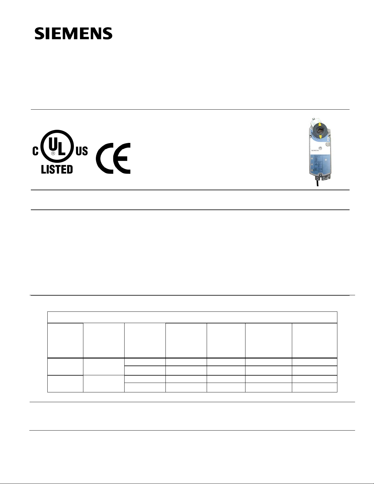
• Required mounting fasteners
ASK71.2U:
OpenAir a
frame. Kit should be used with louvers
and vents and in applications where use
of the floor mount kit is not possible.
Kit contains:
side loading on the actuator’s output
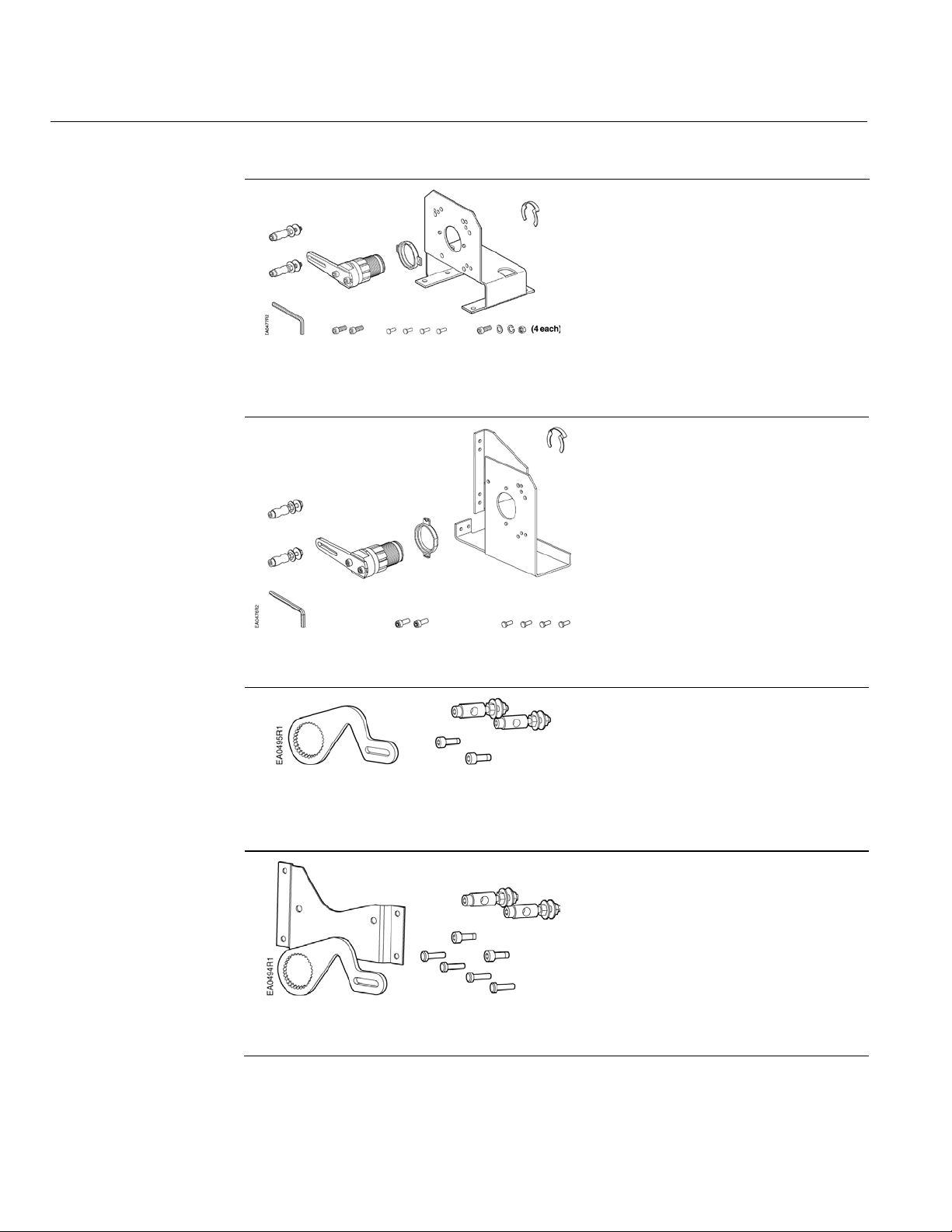
ASK71.3: Kit allows a direct-coupled
actuator to provide an auxiliary linear
drive. Crank arm kit can be
simultaneously drive a set of opposing or
adjacent dampers with a single actuator.
Kit contains:
• Other required mounting fasteners
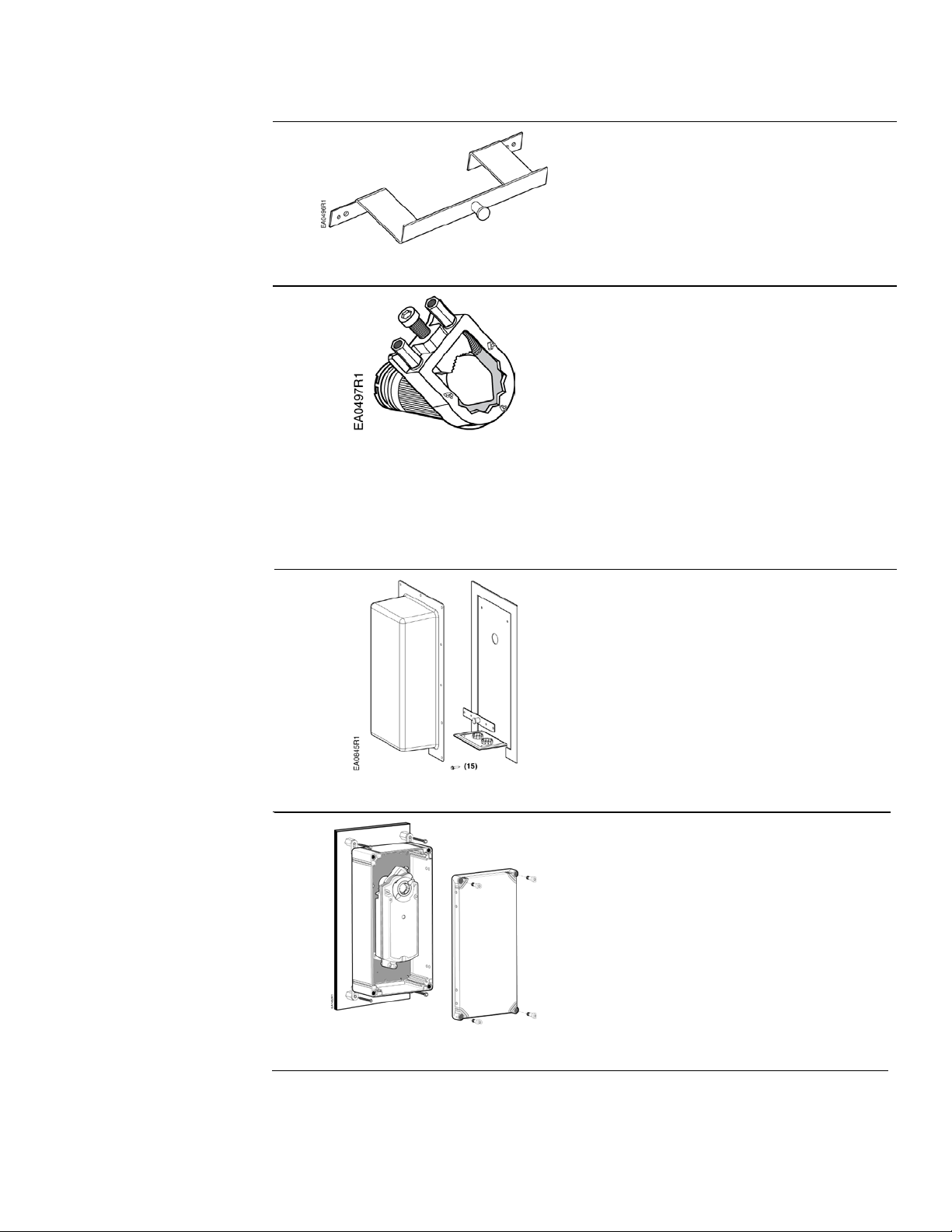
ASK71.4: Kit allows economical mounting
of OpenAir actuators to a variety of
surfaces. Kit should be used in
applications where the actuator can be
rigidly surface mounted and a linear
stroke output is required. Kit contains:
Document Number 155-176P25
June 22, 2015
Accessories
NOTE: Neither the control signal adjustments nor the auxiliary switches can be
added in the field. Order the product numbers that include these options.
Kit allows foot mounting of
-the-air stream applications, and
• Crank arm that changes the angula
Figure 1. Floor Mount Kit.
rotation into a linear stroke
• Support bearing ring to minimize
bearing
• Mounting bracket
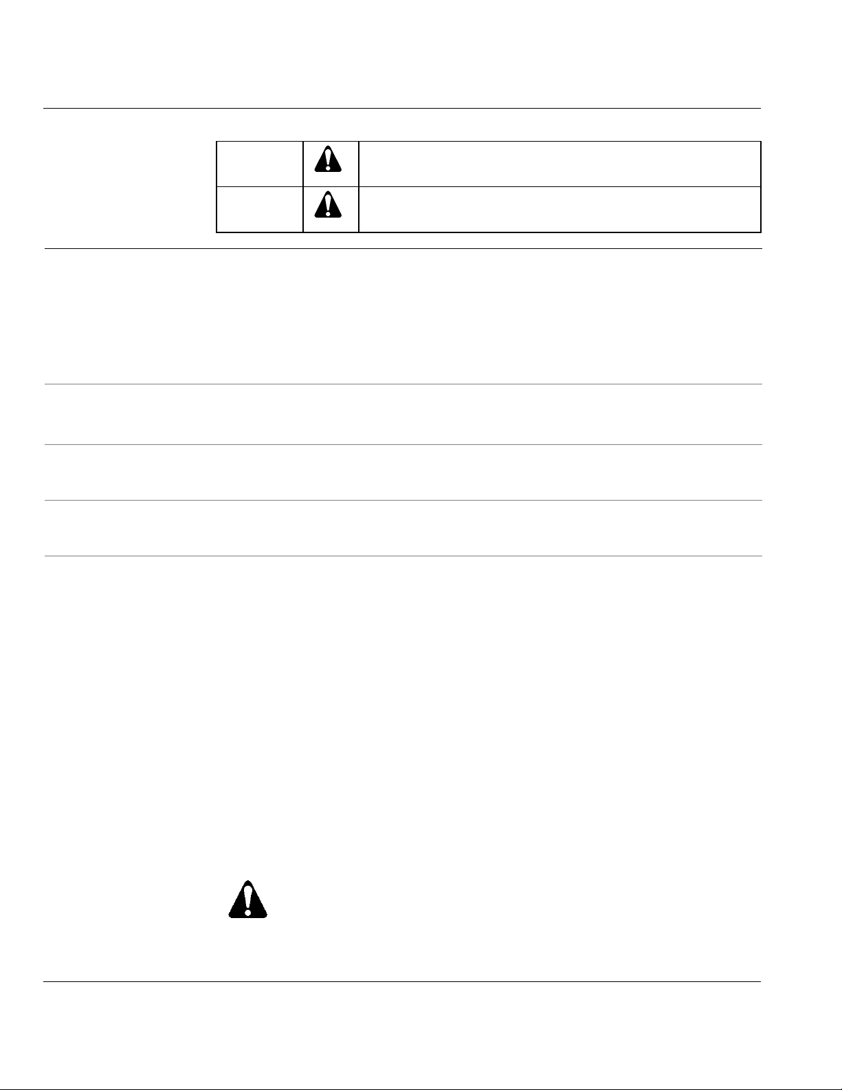
Kit allows mounting of
ctuators directly to a damper
• Crank arm that changes the angular
rotation into a linear stroke
• Support bearing ring to minimize
Page 4 Siemens Industry, Inc.
Figure 4. Crank Arm Kit with Mounting
Figure 2. Frame Mount Kit.
Figure 3. Crank Arm Kit.
Bracket.
bearing
• Mounting bracket
• Required mounting fasteners
• Crank arm that attaches to the
splined hub of the shaft adapter
• Crank arm that attaches to the
splined hub of the shaft adapter
• Mounting bracket
• Required mounting fasteners
used to
GBB/GIB Series Non-spring Return, 24 Vac, Modulating Control Technical Instructions
Accessories,
Continued
ASK73.1U:
rotation pin that allows t
actuators to directly drive a single damper
shaft. For any combination of GIB161x
and GIB166x actuators.
Bracket must be ordered for tandem
installation.
ASK74.1U: Shaft adapter attaches to a
1.05
whereas, the standard self
adapter accepts up to a 1.00
diameter shaft. This special adapter can be
used for coupling to 1
are slightly oversized.
Shaft adapt
shorter than the height of the self
shaft adapter.
985
Small shaft insert (package of
20) when using the GIB actuator on a
damper shaft less than 3/4
diameter.
Document Number 155-176P25
June 22, 2015
Provides an extended anti-
wo modulating GIB
Figure 5. Tandem Mounting Bracket.
Figure 6. Special Shaft Adapter.
-052P20:
ASK75.1U: GBB and GIB Actuators are
UL listed to meet NEMA 3R requirements
(a degree of protection against rain,
sleet, snow and damage from external
ice formation) when installed with
ASK75.1U Weather Shield and outdoorrated conduit fittings in the vertical
position.
-inch (26.6 mm) diameter shaft;
-centering
-inch (25 mm)
-inch jackshafts that
er is 13/16-inches (20 mm)
-centering
-inch (20 mm)
Siemens Industry, Inc. Page 5
Figure 8. NEMA Type 4X Weather Shield.
Figure 7. NEMA 3R Weather Shield.
For dimensions, see Figure 28.
ASK75.7U: GBB and GIB Actuators are
UL listed to meet NEMA Type 4X
requirements (a degree of protection
against falling dirt, rain, sleet, snow,
windblown dust, splashing water, hosedirected water, corrosion, and damage
from external ice formation) when
installed with an ASK75.7U Weather
Shield and outdoor-rated conduit fittings.
This weather shield may be mounted in
any orientation.
For dimensions, see Figure 29.
Technical Instructions GBB/GIB Series Non-spring Return, 24 Vac, Modulating Control
985
NPT connector.
Service Parts
Anti-rotation (Mounting) Bracket.
985-003
985-004
985-006
Document Number 155-176P25
June 22, 2015
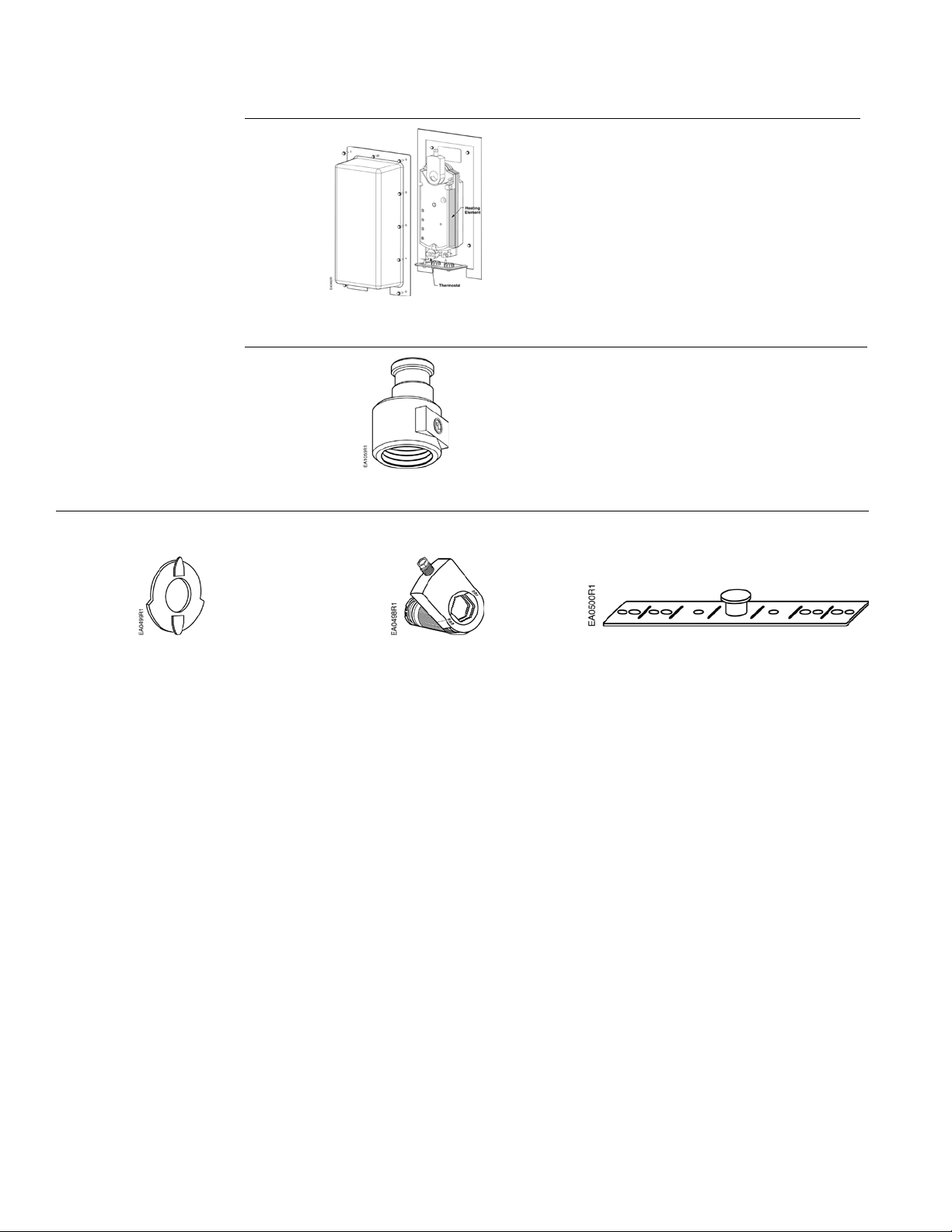
Figure 9. Heater/Weather
Shield Assembly.
Figure 10. Conduit Adapter.
985-106: Provides protection for GIB,
GBB and GCA OpenAir actuators in an
outside low temperature. Assembly
includes:
• Weather Shield (ASK75.1U)
• Heater Kit (985-105)
-008: 1/2-inch (12 mm) for 1/2-inch
Figure 11.
Position Indicator.
(package of 10)
Figure 12.
Standard Shaft Adapter.
Figure 13.
Page 6 Siemens Industry, Inc.
 Loading...