

Page 1
Local Service Organization Service Manual
C
C
C
3
3
3
5
5
5
S
S
S
e
e
e
r
r
r
i
e
i
e
i
e
s
s
s
V1.0
6,(0(16 &20081,&$7,216 81/,0,7('
Page 2

Table of Content
CHAPTER 1
Cellu lar Communication
Coverage Conce p t 1
GSM Network Arc h itecture 2
Subscriber Identity Module 3
SIM Application Toolkit 4
Extended GSM 900 - EGSM 5
Built-in Modem 5
Data A p p lic a tion 6
CHAPTER 2
Lev el 2 Se rv ic e Guide
Introduction 7
C35 Series Technical Information 8
Accessories 10
General Information 11
C35 Series Exploded Diagram 13
Mechanical Concept 14
Hardware Concept – Block diagram 15
Hardware Description 16
Power Supply Concept 18
Over voltage Condition 18
Battery 19
Short Circuit Protection 19
Charging 19
Deep Discharge Battery 20
C35 Spare Parts Level 2 21
Disassemble the C35 22
Disassemble/Assemble Lower Housing 24
Disassemble/Assemble Control Board Assy 25
Disassemble/Assemble Upper Housing 27
Assemble the C35 28
Mobile Software Programming 30
Language Groups 32
Custo me r S p ecific Initialization 34
International Mobile Equipment Identity 34
Phone Unblocking 35
CHAPTER 3
Siemens Service Equipment
Introducti on 37
Other equipment 39
Softwa re Installatio n 40
Configuring the test software 41
Running the test sequence 42
ANNEX A 46
ANNEX B 49
CHAPTER 4
Level 2.5 Repair Document
Introduction 50
Antenna Connector 51
Ringer 55
Bottom Connector (Lumberg) 58
Display Connector 62
Keyboard LED 66
Display LED 69
Infrared Diodes 73
ANNEX C
PC Adapter Cable & Accessories C35 76
Power Plug for C35 77
Car installation Ratio Unit, C35 78
Car Installation kit Handfree kit 79
Car Installation kit Handfree Pro. 80
Car Insta lla tio n Comfort GPS, C3 5 81
Reference s 83
i
V1.0
Page 3
Cellular Communication
C
T
hapter
Coverage Concept
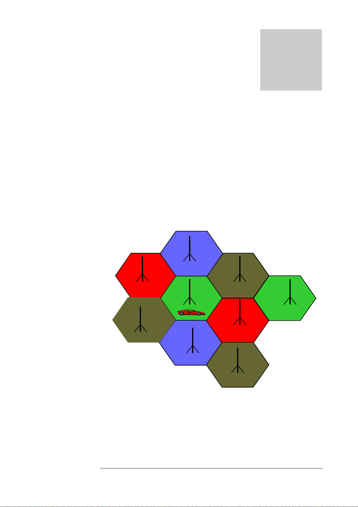
he cellular systems is made up of numerous transmitting and
receiving sites, whose individual coverage areas partially overlap. The
concept of frequency re-use, sam e frequency i s used by several sites,
allows a high traffic density in a wide area. Due to the limited
transmission range of the terminals, cellular systems are based on a large
number of base stations on the infrastructure side, scattered over the area to
cover, wi th each c ov eri ng a fair l y s m all geogr aphi cal z one cal l ed cel l . C el ls are
often represented by hexagons (s ee figure 1.1.) .
.
FIGURE 1.1
V1.0
CELLULAR COVERAGE R EPR ESENT ATION.
1
Page 4
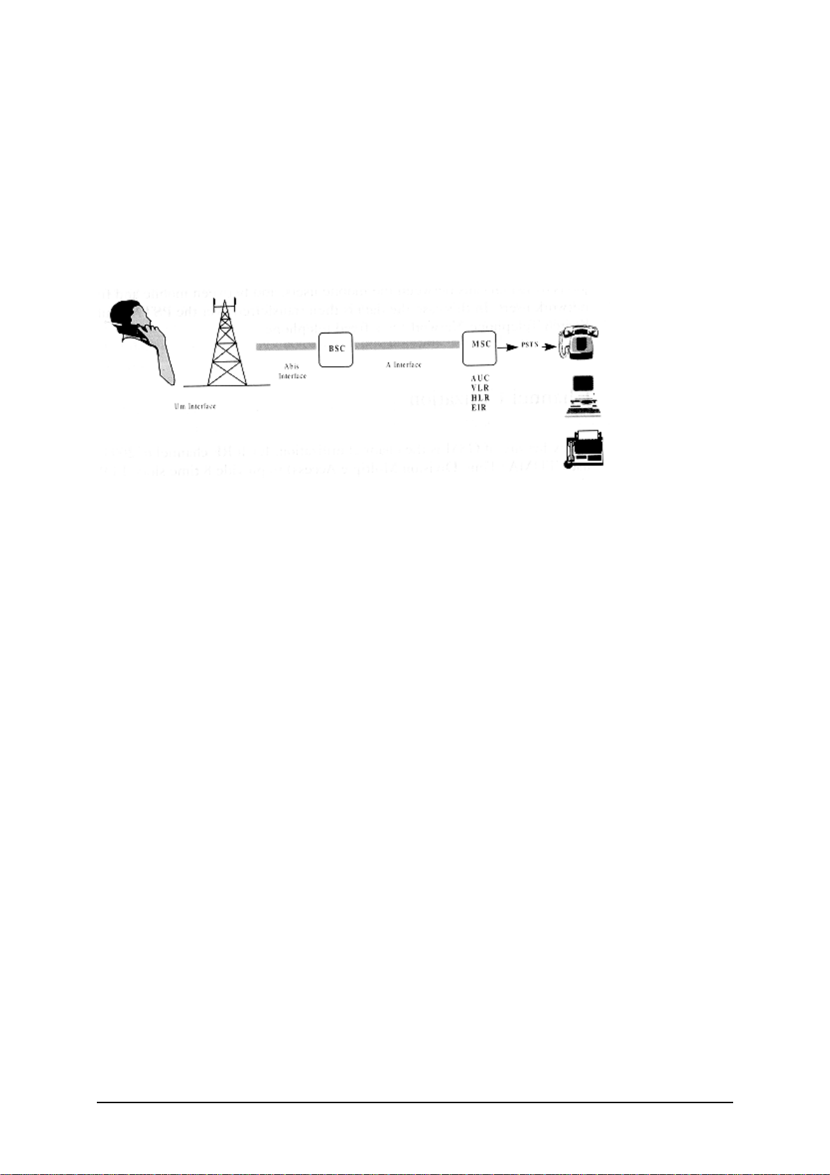
GSM Network Architecture.
GSM networ k c an be broadl y div ided i nto thr ee br oad par ts, nam el y:
1. Mobile Stati on( MS) carried by the subs cr i ber ,
2. Base Station Sub-system(BSS) whi ch contr ol s the r adio l i nk wi th the m obil e station.
3. Mobile Switching Center(MSC) which performs the switching of calls between the mobile
users, and between m obil e and fixed netw ork user s .
FIGURE 1.2 GSM ARCHI TECTURE
Each mobile station is given a unique identity. As soon as the mobile phone is turned on, it
registers with the network and is authenticated, as such the network could always find the
mobile phone.
Larger amount of data is being exchanged to and from the following functional blocks in the
MSC:
Visitor Locati on R egis ter , VLR
Stores information about mobile subscribers that enter it coverage area which is associated with
the geographical area where the mobile is currently roaming. When there is an incoming call for
the mobile, the HLR is inter r ogated about the pr esent addr es s of the VLR.
Home Location Regi s ter , HLR
A database that contains all data concerning the subscription of the mobile subscriber, i.e. their
access capabilities, subscribed services, and supplementary services. It also contains
information about the VLR that is handling the mobile station currently. When the mobile
changes location, the HLR is updated accordingly. It also provides the MSC with information
about the MSC area where the mobile is actually located to allow incoming calls to be routed
immediatel y to the c all ed par ty.
2
V1.0
Page 5
Authentication Center, AU C
Stored information that is necessary to protect communication through the air interface against
any intrusions. The legitimacy of the subscriber is established through authentication and
ciphering, whi c h protec ts the us er inform ati on agains t unwanted di s cl osur e.
Equipment Identit y R egi ster , EIR
An option the network operator can use to enforce security. With this feature the network can
identify defective or stolen m obi l e that m ay not be used i n the netw or k.
Subscriber Identi ty Module(SIM)
SIM is a smart card which has a computer and memory chip that is permanently installed in the
mobile equipment. It comes in either the size of a credit card or smaller version known as the
plug-in SI M.
1
The subscriber information, which includes a unique number called the International Mobile
Subscriber Identity (IMSI) is stored in the SIM card. SIM card identifies the subscriber to the
network.
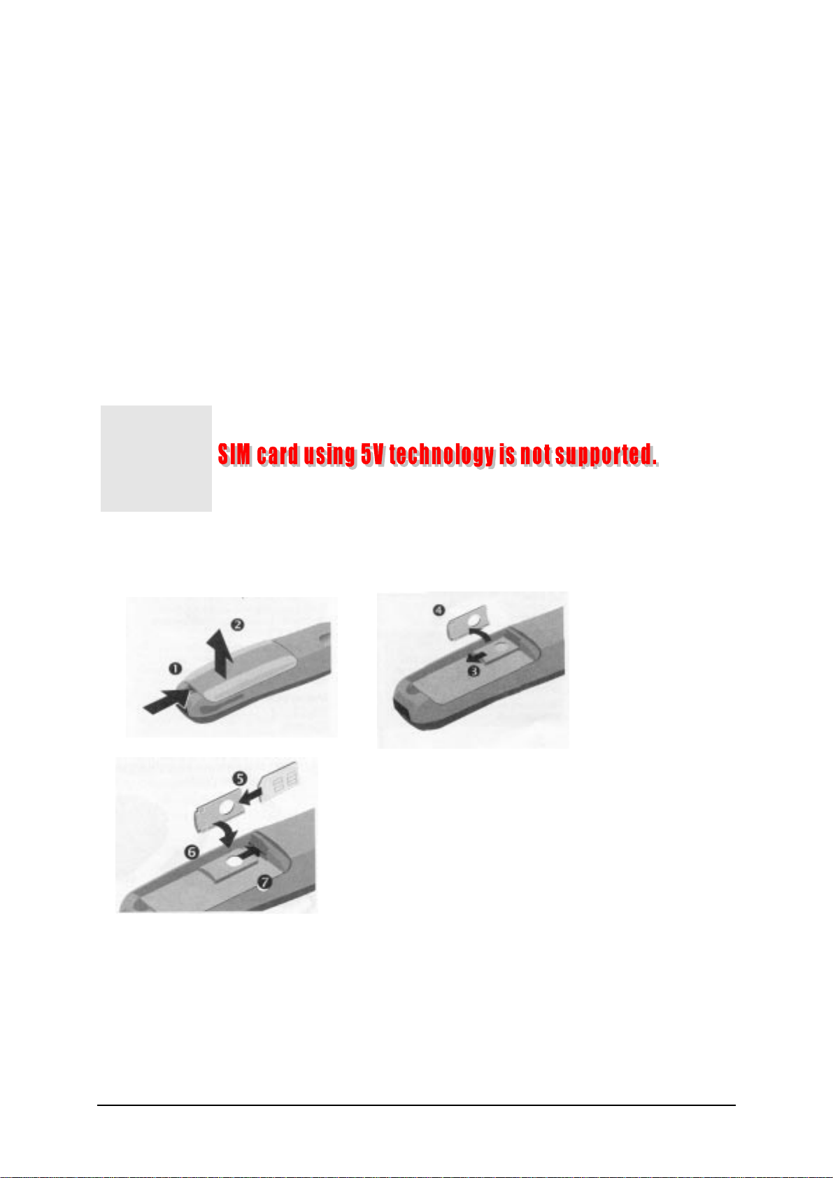
FIGURE 1.3 I NSERT SIM CARD
Figure 1.3 illustrates the steps for inserting the SIM card into the C35 series.
3
V1.0
Page 6
To protect the SIM card from impr oper use, a s ecur i ty feature, a four digits personal identification
number (PIN), is built in. The PIN is stored in the card and can be changed by the subscriber.
PIN2 is r equi r ed for additi onal funtions avai l abl e wi th a s peci al SI M card (Consul t the operator for
more information about the PI N .
A code (PUK) i s pr ov ided for unl ock i ng the SI M card if the SIM c ard i s bloc ked
Β
Change PIN Procedures.
MENU
SETUP
SECURITY
CODES
CHANGE PIN CHANGE PIN2
{ENTER PIN NUMBER}
CHANGE
{ENTER NEW PIN} AND PRESS OK KEY.
{ENTER NEW PIN) AND PRESS OK KEY.
CHART 1.1 PIN CONTROL
SIM Appli cation Toolkit
SIM Applications Toolkit (SAT) allows the fle xibility to update the SIM, to change the services
and download new serv i ces ov er the ai r. I n the SAT spec ificati on, the short mess age servi ce is a
4
V1.0
Page 7
key mechanism for personalizing the SIM in each user’s GSM phone. It is designed as a clientserver appli cati on. C 35 ser i es s uppor ts SAT Cl as s 3 s peci fication.
When active, the name of the service may appear in the menu, and there will be sub-menu if
more than one applicati on i s ac ti ve. F igur e 1.6 i s the SAT i con.
FIGURE 1.4 SAT ICON
Extended GSM 900, E -GSM
This is a new standard that allows Network Operators to increase their capacity through an
extended frequency. The frequency range of E-GSM is as follows:
• Mobile T r ansm i t: 880 – 915 MHz
• Mobile R ec eiv e: 925 – 960 MHz
C35 series i s a GSM Phase 2 / Phase 2+ Dualband E-GSM / GSM 1800 mobi le phone.
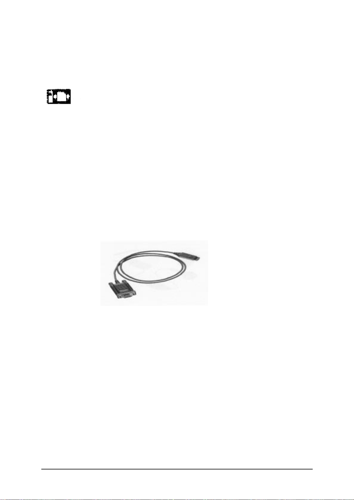
Built-i n Modem.
C35i has an integrated modem for direct data communication using the data cable as shown in
Figure 1.5. C35 do not have the bui l t- in s oft modem for Data Ser vi c e of GSM networ k .
FIGURE 1.5 DATA CAB LE.
5
V1.0
Page 8

Data Applicati on Support
Modem driver conforms to V.25 command set, and transmission speed conforms ITU-Tstandard of V.22bis. (2400, 4800,and 9600 bits /sec ) .
Facsimi le c onforms to Ser vi ce C l ass 1, gr oup 3 and oper ate at 2400, 4800, 7200 and 9600 bit/s .
Data servic es vi a GSM network up to 9600 bps, and remote control using cellular AT commands
for C35i only.
Internet acces s v ia the C 35i is poss ibl e w i th the inc l usi on of Wireless Applic ati on Protocol (WAP)
browser 1.1 .
6
V1.0
Page 9

C
hapter
Level 2 Serv ice Guide
Introduction
The chapter is intended to help you carry out repair up to Level 2 on the C35 series mobile
phone.
The repair for international version and Asian variants are identical unless otherwise noted,
therefore the descripti on her ein i s confined to C35 onl y.
All repairs have to be carr ied out in an envir onm ent set up
according to ESD r egulations defined in inter national standards.
ESD procedu r e is av ailable fr om y ou r S ervice Manager. A sk for
ASC/T001/98
7
V1.0
Page 10

C35 & C35i Techni cal Information
System GSM Phase 2/Phase2+, D ual Band
EGSM 900, Clas s 4( 2 Watt)
GSM 1800, Clas s 1( 1 Watt)
Operating Voltage 3.6V
Size(LxWxH) 118 x 46 x 21 m m ( wi thout antenna)
3
Volume 88c m
Weight 116g including battery (approx)
Battery(Standard) NiM H , 500m AH( Standar d)
Li-Ion, 600m AH (O ptional )
including battery ( appr ox)
Standby time
Talk time
1
1
50 to 180 hours (standar d battery )
90 to 300 minutes (standar d batter y )
Charging Ti m e Up to 1.5 hours wi th R apid C har ger
SIM suppor t Plug in card 1.8 V or 3V
Antenna Non - retr ac table, λ/2, heli c al fixed.
Speech codec Triple r ate
Enhance Full Rate
Full Rate
Half Rate
Display 101 x 54 pixel gr aphi cal di spl ay wi th up to 5 l i nes
12 x 12 font size for Chinese
Keypad 12 numeric key s( 10 num er i c, #, *)
4 function keys(Send, End-ON /OFF , Menu, Phonebook)
2 multifunctional s oftkeys
Key Sound Click/DTMF/None
Key Lock Activation and Deac tiv ati on by #- key or
Automatic.
1
Actual time depende nt on the network.
8
V1.0
Page 11

Dialing 10 redial number s ,
Last 10 incoming w it h date/tim e s tam p
Last 10 outgoing calls
Last 10 missed cal l s w i th date/ti me s tam p
Ringer On/Beep/Off
Up to 22 melodies and 5 r i ngi ng vol um e setti ngs
(Mel ody C om pos er , Cr es cendo R i ngi ng)
Volume Adjustable in 4 levels during call via softkey
Silent Alert Built-in v ibr ator
Phone Book Storage depends on the SIM card capacity
Storage of up to 100 list in the phone (VIP)
SMS Support MT, MO, CB
Predictive T ext I nput, T egic T9.
Supplementary Call Forw ar di ng, Cal l Hol d, C all Wait,
Services Multiparty C onference, C LI P, C LI R , AoC C
AoCI, FDN , LN D U SSD and SAT .
Ciphering A5/1 and A5/2 supported
PIN control PIN 1 & 2 Code Control
Phone code 4 to 8 digit code
Network function Automatic and manual networ k sel ecti on
Chipset Siemens E – GOLD
WAP Browser
1
Version 1.1
Other Features Clock / Alar m
Alarm List
Built-in m odem
Calculator
2
3
4
Currency Conv er ter
4 Games
7 User Profiles
1
Only for Model C35 i.
2
Not available in C35 International version.
3
Not available in C35 International version.
4
Not available in C35 International version.
9
V1.0
Page 12

Accessories:
1. Standard Battery L36880-N4001-A100
2. Optional Battery L36880-N4001-A101
3. Standard Charger L36280-Z4-C XXX ( Countr y Vari ant)
4. Travel Char ger L36880-N4001-A103 (EU ) / A104 ( U K)
Similar to standar d c har ger wi th an uni ver s al i nput vol tage from 90 ~ 240V
4. Desk Top Char ger L36880-N4001-A102
5. Belt Clip L36880-N4001-A113
6. Headset L36880-N4001-A123
7. Antenna Cradle L36880-N4001-A110
8. Car Charger C abl e L36880-N4001-A108
9. Car Kit Portabl e
1
L36880-N3015-A117
10. Car Kit Comfort L36880-N4001-A111
11. Car Handset
2
L36880-N3015-A123
12. Designer Cases L36880-N4001-A119
13. Soft Data Link 3.0 L36880-N4001-A122 (Not for 3508i)
14. Data Cable
3
L36880-N3101-A102
15. Car Kit Professional Voi ce L36880-N4001-A124
16. Data Cable Professional
4
L36880-N3101-A112
1
Same as C25(88)
2
Same as C25(88)
3
Same as C25(88)
4
Same as C25(88)
10
V1.0
Page 13

General Information
Due to different requirements of the markets, the C35 series has different variants, which
broadly classified under International version and Asian version. Marketing name for
international ver s ion i s C35 or C 35i , wher eas Asi an ver s ion i s nam ed 3508 or 3508i .
The 3508 series is equipped with a graphic display which enable the telephone to display
CHIN ESE char acter s , either i n T radi ti onal font or Sim pl ified font, beside the st andard Engl i sh.
Difference between C35(08) and C35(08)i
C35(08)i mobile software has WAP Browser 1.1 incorporated thus enabling user to surf the
Internet and it hav e buil t- i n soft modem for GSM Data Service.
The differences between the C35 and C35i are the hardware and software. The memory size of
C35 is 16M B and that of C35I i s 32MB.
There are also two variants for 3508, one without the WAP browser is 3508 and that with WAP
browser ver s ion 1.1 i s 3508i . T he different for ASIAN ver s ion i s only m obil e softwar e.
Wireless Appli cation Protocol, WAP.
Wireless Application Protocol takes a client-server approach that uses the in-built micro-browser
to make a request, in wireless markup language (W ML), for information or service. The request
is passed to a WAP Gateway which then retrieves the information from a Internet server, in
HTML format, and translate it into WML. The requested information is then sent to from the
WAP Gateway to W AP client (mobile) using the available and most appropriate mobile network
bearer serv i ces .
Wireless Protocol Stack.
Wireless Application Envi r onm ent ( WAE)
Wireless Session Protocol ( WSP)
Wireless Transaction Pr otoc ol ( WTP)
Wireless Transport Lay er Sec ur ity ( WTLS)
Wireless Datagram Pr otocol ( WDP)
Bearers e.g. Data, SMS, USSD
TABLE 1..1 WAP PROTOCOL STACK
1. Wireless Application Environment
Defines the user interface on the phone. WAE contains the WML,WML script and the
wireless tel ephony appl ic ati on ( WTA).
11
V1.0
Page 14

2. Wirelss Session Protocol
Link the W AE to two session services – one connection oriented operating above the WTP
and a connectionless ser v ic e oper ati ng above WDP.
3. Wireless Transaction Pr otoc ol
Runs on top of the datagram service and part of the standard suite of TCP/IP protocols, to
provide a sim pl ified pr otocol s uitabl e for low bandw i dth mobi l e stati on.
4. Wireless Transport Lay er Sec ur ity
WTLS incorporates security features that are based upon the established Transport layer
Security (TLS) protocol standard, that include data integrity checks, privacy on the WAP
Gateway to client l eg and authentic ati on.
5. Wireless Datagram Pr otocol
Allows W AP to be bearer independent by adapting the transport layer of the under-laying
bearer. WDP presents a consis tent data format to the hi gher lay er on the WAP stack.
12
V1.0
Page 15
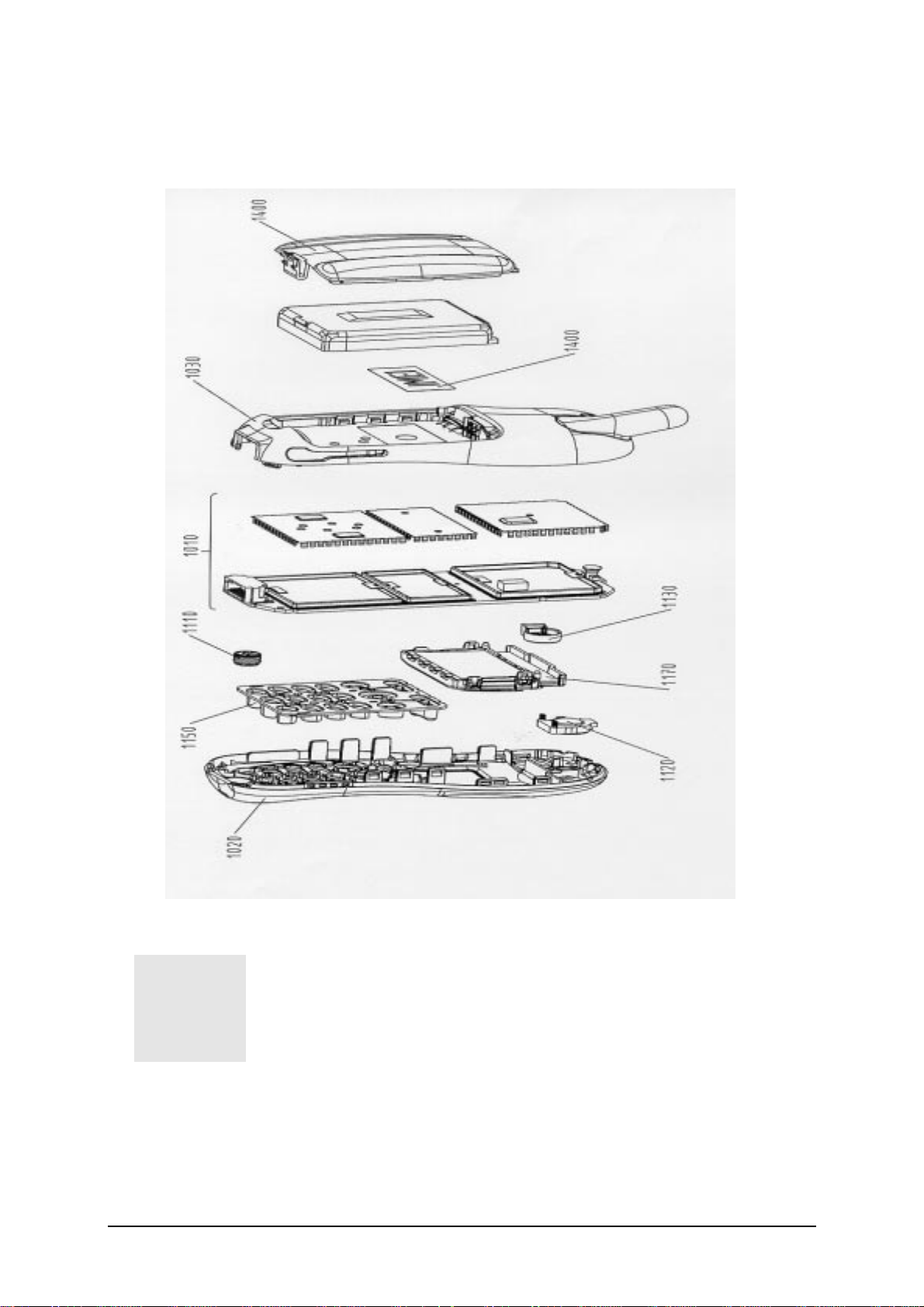
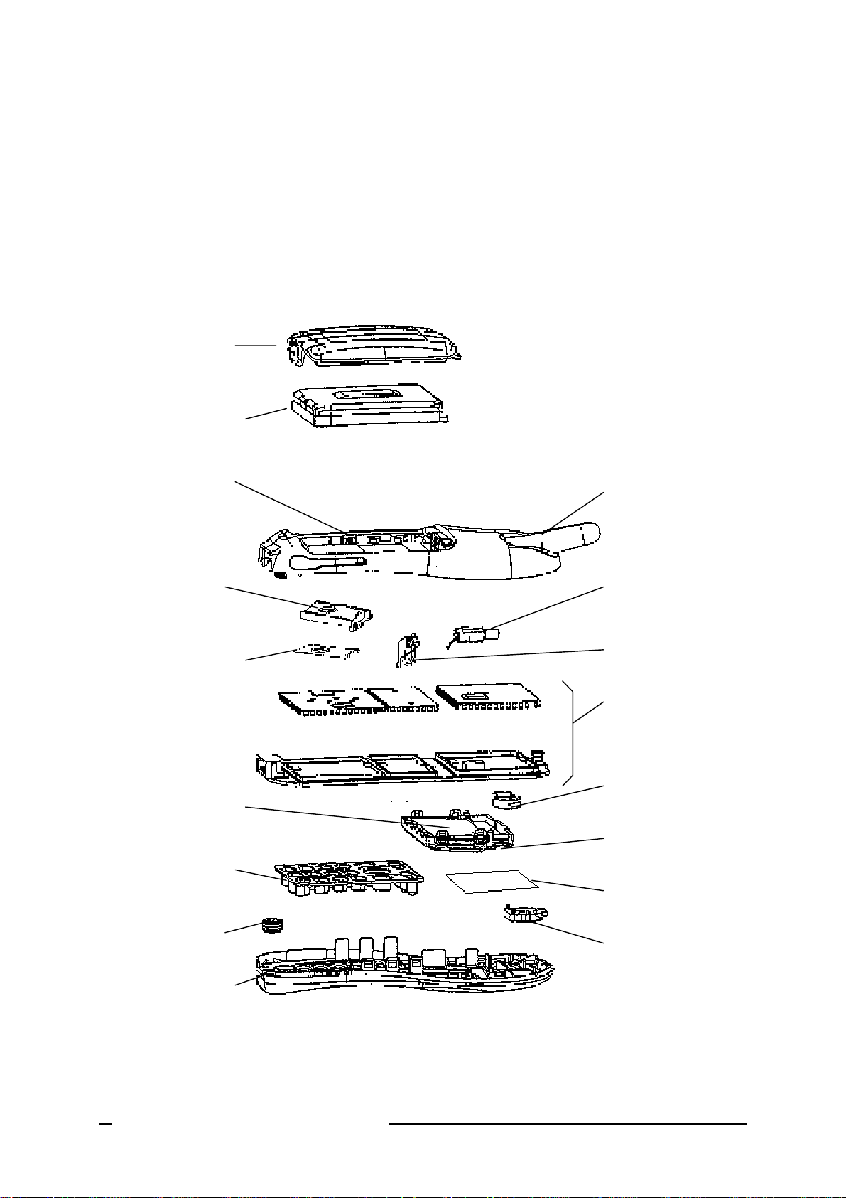
C35 Series Mechani cal Diagram
1
V1.0
FIGURE 2.1 C3 5 M ECHANICAL DIAGRAM .
Please take note that the number(s) used here IS NOT the part
number, DO NOT used it in your spare parts purchase order.
Always refer to the SERVICE PART PRICE LIST
for your spare part order.
13
Page 16

Mechanical Concept
1
Note: All numbers refer to mechani cal drawing in Figure 2.1.
The mechanical conc ept of the C35 differs in var i ous poi nts from the one of the other Si em ens
mobile telephones.
The first thing you will experience is how the housing is locked. In C35 no s cr ew s ar e used to
keep the housing closed. Al so i nsi de the tel ephone no sc r ews ar e used any m ore. T o open the
housing, which i s k ept cl osed by catc hes onl y, a s peci al opening tool has been defined.
details on disass em bly tool pleas e r efer to Photo 2.3 i n thi s c hapter
Inside, the C35 c onsi sts of just one boar d ( 1010) whi ch c ar r ies di spl ay m odul e( 1170), c ontr ol
part and RF secti on of the mobil e.
The display m odule ( 1170) i s c onnected to the boar d by a flexibl e cabl e w hic h i s i nser ted i nto a
plug. In case the di spl ay i s defectiv e elec tr i cal ly or m echani cal l y i t can be ex changed v er y eas il y.
C35 does have an external connec tor of a new ty pe. Sinc e S6 a so c all ed “ Molex”-connector
was used, which also offered the possibility to connect an external antenna to it. T he new
“Lumberg”- c onnector w hic h i s us ed in C 35 does not feature s uch a connec ti on, becaus e the
connector for external antenna is loc ated at the back si de of the upper end of the mobil e, cl ose
to the internal antenna (1130) . As a c onsequenc e of this ther e is no need anym or e for a RF
cable mounted to the board nor for a RF plug on i t to c onnect thi s c abl e. Thi s i m pr oves RF properties of the mobil e and l ower s pr oducti on cos ts.
.
For
To be able to do measurem ents on and softwar e update of the telephone, an adapter c able
between Mol ex and Lum ber g c onnector will be available.
Chapter 3
C35 series antenna i s of a snap- in ty pe whi ch i ns ert ed into the l ow er c ase s hell ( 1030) . The
antenna can only be changed by openi ng up the C35 phone.
The keypad (1150), the m i cr ophone ( 1110) and the l oudspeak er ( 1120) ar e m ounted i nto the
upper case shell (1020) . Make sure that the micr ophone and the ear phone c ontact s pri ngs are
not dirty or dam aged dur i ng r epai r pr oces s.
The dust protection fram e and the dis pl ay w i ndow ar e i ncl uded i n the di spl ay m odul e( 1170) .
.
The C35 is a dual-band mobile operating on GSM900 and
GSM1800, the antenna is an integral part of the lower housing.
See photos in Additional T ool s of
14
V1.0
Page 17
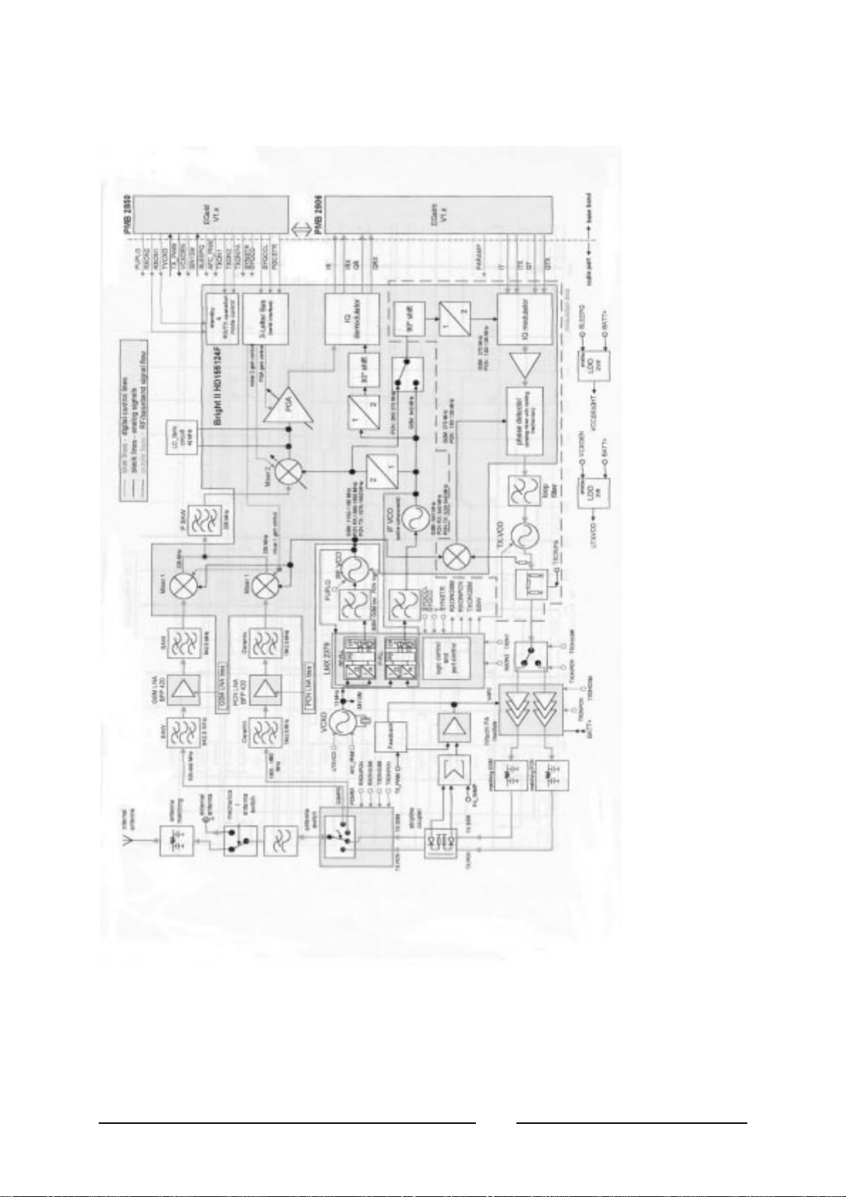
Hardware Concept – Block Di agram
FIGURE 2.2 C35 BLOC K DIAGRAM.
15
V1.0
Page 18

Hardware Description
The handset consists of the following m aj or i ntegr ated ci r cui ts :
E-GOLD – PM B 2851E
1)
This IC i s a com bi nati on of mic ropr oc ess or , si gnal proc ess or and r eal- ti m e cl oc k.
The micropr oc ess or part of this com ponent i s r espons ibl e for contr olli ng the key boar d, SI M-
Card, Flash and R AM. Furthermor e it contr ol s the pow er sav ing, pow er up/pow er dow n of the
RF module and sets the am pli ficati on of the PA.
The signal proc ess or part of PM B 2851E i s res ponsi bl e for proc ess ing the R x I /Q si gnal s
(filtering, equal iz ing, s peech and c hannel decodi ng) .
Furthermor e i t does the s peech and c hannel encodi ng and the GSMK modulation of the Tx
I/Q signals . T he Voic e CO DEC par t i s us ed to real i ze adv anced features regar di ng codi ng of
the speech signal. T hese ar e:
• Halfrate-Encoding
• Halfrate-Decoding
• Enhanced Fullr ate Encodi ng
• Enhanced Fullr ate Dec odi ng
• Voice Activity Detection
• Comfort Noise
GAIM – PMB 2906
2)
The GAIM ( GAI M = GSM Analog Interfacing Module) provi des the i nter face between the
analogue and its digital r epr esentati on s ignal s ( Bas e- band I /Q, Voi ce- band, PA- c ontrol ,
Voltage & Temperatur e Measurement - Char gi ng contr ol ) .
13Mhz Ref Oscillator Circuit -
3)
This cir cui t pr ovi des the foll owi ng m ai n functions:
• Generate 13Mhz c l ock si gnal for Logi c C i r cui ts – SIN13M.
• Generate 13Mhz r eference s i gnal for the PLL c ir c uits for the Tx & Rx of GSM RF si gnal .
• Received the frequency st eeri ng c ontr ol AF C_PN M from the HiGOLD I C for fine tuning
of the Tx & Rx frequency.
• Temperature dependent r esi s tor si ted near the 13MHz oscillator measure the
environment tem per atur e.
16
V1.0
Page 19

Power Supply A SIC – D0767B A
4)
This cir cui t pr ovi des the foll owi ng m ai n functions:
• Control of switc h on of the M obil e phone by ON /OF F button, Ex t Power ( C har ger ) or r eal
time clock.
• Watchdog monitor – switch off the mobile phone if no proper Watchdog signal send from
HiGOLD IC.
• Voltage supply to the logic ci r cui ts – 2.90V, 2.65V & 1.92V, Sim c ar d & r eal ti m e c loc k i n
HiGOLD IC.
• Switch on the linear regul ator to suppl y the 2.8V for the13M hz Oscillator circuit.
• RESET signal for the logi c ci r c uit.
• Charge control si gnal for sw i tc hing the c har ge F ET.
• Low battery detector.
• Over voltage protec ti on.
Receiver C i rcu it – Brigh t I I HD155124F
5)
This cir cui t pr ovi des the foll owi ng m ai n functions:
• Low Noise Ampl i fier ( LN A) wi th a fixed am pl i fication of +20dB to ampl i fy the input R F
signal.
• Mixer to m i x dow n the R F s ignal to the Intermediate Frequency ( I F )
• Programm able IF amplifier wi th a dynam i c r ange of 60dB ( - 10dB ~+ 50dB in s teps of
2dB).
• Mixer to m i x dow n the I F si gnal to the baseband, gener ati ng and i nphase ( I ) and a
quadrature (Q) si gnal and feed the GAIM IC base-band si gnal , RX I /Q for the decodi ng
of the digital signal for the Hi GOLD I C .
Transmitter Ci rcu i t – B right II HD155124F
6)
The GAIM IC generate the MOD I /Q bas e- band si gnal under the contr ol of the HiGOLD I C
and feed the IQ modulator of the Bright II IC. The Br i ght II IC pr ovi des the IF synthesizer,
the I/Q modulator , pr esc al er to r egul ate the dual - band TX- VC O and feed the modul ated GSM
signal to the PA.
The telephone support only 1.8V and 3V S I M car d
For user with 5V SIM card, he need to upgrade the SI M car d
1
through his service provi der/ network oper ator
17
V1.0
Page 20

Power Supply Concept
The C35 has two mai n pow er inputs :
1. Battery voltage(3.6V) c onnected at the batter y contac t
2. Charging voltage(6.5V) delivered by the diff erent charger type(see Accessory List) via the
Lumberg connector at the bottom of the telephone.
Since the battery voltage is supplying the power supply ASIC, it is always needed to operate the
phone.
From the battery voltage, all other supply voltages are derived and controlled by the power
supply ASIC .
The RF power amplifier is directly connect to the battery, a bad battery with high internal
resistance c an c ause m al function of the C35 phone.
The Logic module us es 1.92V, 2.65V & 2.9V gener ated by vol tage r egulator s i nsi de the ASI C .
Furthermore, the ASIC generates the supply voltage for the SIM card and the RESET signal for
the logic devic es.
You cannot switch on the handset if the battery voltage is not present.
The ASIC also checks the presence of the watchdog signal from the microprocessor and
provides the sw it chi ng on functionali ty ( ON _OFF button or I gni tion s i gnal) .
Wrong polarity or battery voltage setting that exceed the + 6.5V
could damage the phone.
1
Over-voltage Conditi on
• Battery voltage
If the supply voltage rises above 6.2V, the phone will switch off and it cannot be switched on
again before the voltage is l ower than 6.2V.
If the supply vol tage r is es above 7V, the phone c an be dam aged
• Charging Current
The charging current must not rise above 1A or a track fuse in the
phone will blow. As a result charging the battery will no longer by
possible.
1
18
V1.0
Page 21
Be careful with NON-original S I E MEN S accessories or char ger s. Make sur e that
the charging current is limited to value below 1A.
Battery
C35 series uses a Nickel Metal Hyride (NiMH) 500mAH battery pack as standard battery. It also
support the Lithium Ion 600mAH battery pack (For S35i phone) as optional battery for customer
want longer talk ti m e.
PHOTO 2.32 C35 SERIES INSERTING BATTERY.
For C35, BATT+ has a voltage level from +3.0V to 5.5V, and a BATT_TEMP contact is used for
detecting abnormal inc r ease i n tem peratur e of the battery .
If the temperature is too high or too low, there is a high probability
that the battery is not charged. To enable the charging pr ocess
again, battery and phone needs to cools down or war m up. B atter y
replacement is not requir ed.
1
Avoid shorting the battery terminals.
Short Circui t Protection
For the Nickel Metal Hydride battery, a polyswitch in the battery pack protecting the battery from
short circui t and i t shoul d r eset by i ts elf after some tim e r emov ing the s hor t ci rc ui t.
For the Lit hium Ion battery, it is short-circuit prote cted by an ele ctronics fuse . The fu se will be
activated in case a too high current is drawn. This fuse will
The resetting of the L-ion batter y fuse can be done w it h either of the followi ng pr ocedur es:
1. Insert the battery into the C35 and then connect the rapid charger to the phone. Wait for
approximatel y 10 s econd, then the m obi le c an be tur ned on again.
2. Plug the battery separatel y into the des ktop c har ger . The fuse is res et im m edi atel y.
not reset
automatically .
3. Insert the battery into the C35 and put the phone into the desktop charger. Wait for
approximatel y 10 s econd, then the m obi le c an be sw i tched on.
Charging
The battery can be charged when it is inserted into the phone. The charging process is
completely contr ol l ed by the m obi le. C har gi ng can be done w i th any of the followi ng acc ess ory :
19
V1.0
Page 22
1. Rapid charger
2. Travel charger
3. Car charger
4. Desktop charger
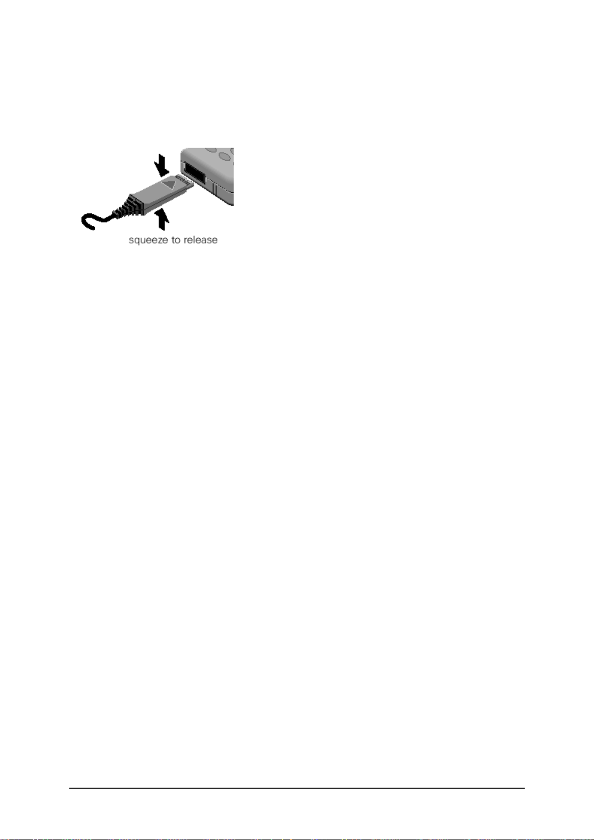
PHOTO 2.33 INSERT CHARGER
Photo 2.33 shows the corr ect w ay of inser ti ng and r em ovi ng the char ger pl ug.
Deep Discharge Battery
In case of a deeply disc har ged batter y, the v oltage of the battery is too l ow to oper ate the
charging cir c uit and the di spl ay c ontr oll er , the phone c an not be tur ned on and the norm al
charging proces s c an not be star ted. N o char gi ng sy m bol is vi si bl e in the di s play .
In this case, c har ging the batter y is di vi ded i nto two di fferent steps, whi ch hav e to be r un
subsequently:
Trickle charge for C35 Phone
a)
Trickl e char ge m ode i s autom ati cal l y s tar ted if the battery vol tage i s bel ow 3.0V w hen the
charger is c onnected to the m obi l e. The c hargi ng c urr ent i n T ri c kl e m ode is appr . 10m A.
Trickl e char ge m ode has to l as t m ini m um until the batter y vol tage has ex ceeded 3.2V,
then the phone will switch on and the charging icon appear. During tr i ck l e char ge the
charging symbol will not be visible and the telephone can not be turned on. This is
because the battery volt age is too l ow to oper ate the tel ephone.
Action:
Insert batter y i nto handset and c onnect tr av el char ger to the tel ephone. I f wi thi n 4 hours
the battery voltage is hi gh enough again, the c har ging s ym bol will come up.
If the battery is di schar ged v er y deepl y, the s ym bol m ay not c om e up and the tri c kl e
charge time poss ibl y has to be ex tended up to 24 hours .
Norm al charge
b)
When the battery voltage is above the a.m. val ue (e.g. by tr ic kl e c harge) the m obi l e will
start the normal char gi ng m ode and show a char gi ng s ym bol in the di spl ay. * Al way s
normal char ge a new batter y or a deep dis char ged batter y for mor e then 12 hour s before
first use.
Action:
Connect charger to the tel ephone (
20
V1.0
see section on Char gi ng
).
Page 23
The charging symbol will come up as an indication that the normal charging process has
been started by the mobi le.
Mobile Phone C35 S pare Parts Level 2
Battery Cover
L36158-A33-B....
Battery NI-MH
L36145-K1310-X125
Lower Cas e Sh el l
L36880-A33-B....
Antenna
L36158-A33-B161
SIM Card Reader
with
Card Holder
L36334-Z97-C111
SIM C ard Holder
L36334-Z97-C 112
Display modul e
L36851-Z1508-A51
Keypad
L36158-A33-B75
Microphone
L36254-Z6-C82
Upper Case Shell
L36158-A33-B....
Vibra-Alert Unit
L36453-Z5-C 77
Battery Contact Spring
L36334-Z97-C113
RF Control Board
L36880-Q4050-B201
Buzzer Sealing
L36158-A33-C260
Display Cover
L36851-A33-C101
Display Sealing
L36158-A33-C103
Earphone
L36212-Z3-C34
L36158-A33-B....see Spare Par t
21
V1.0
Page 24
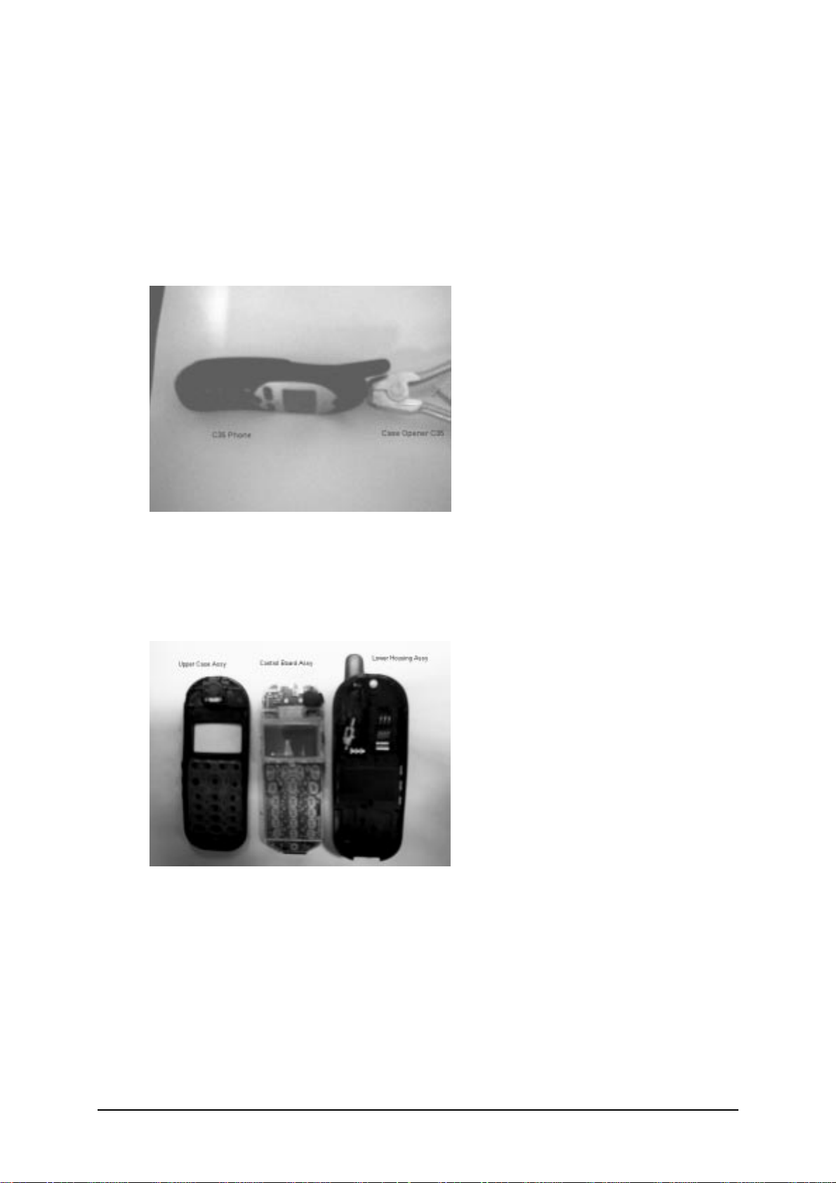
Disassemble the C35
1
A case opener is needed to di sengage the l atch of the C35 cas ing.
PHOTO 2.3 C35 CASE OPENER
The part number for this mandatory tool i s F30032-P46-A 1
Refer to ANNEX B of Chapter 3 for S ervi c e Eq uipment List.
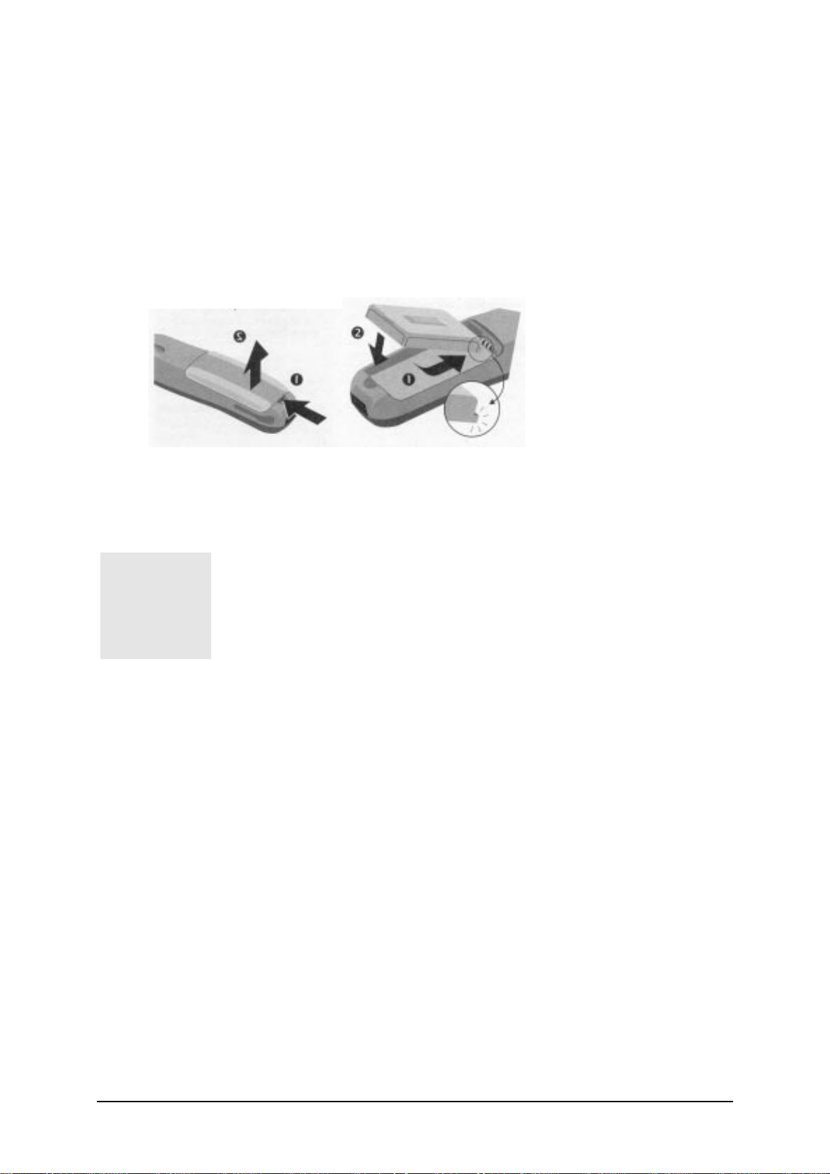
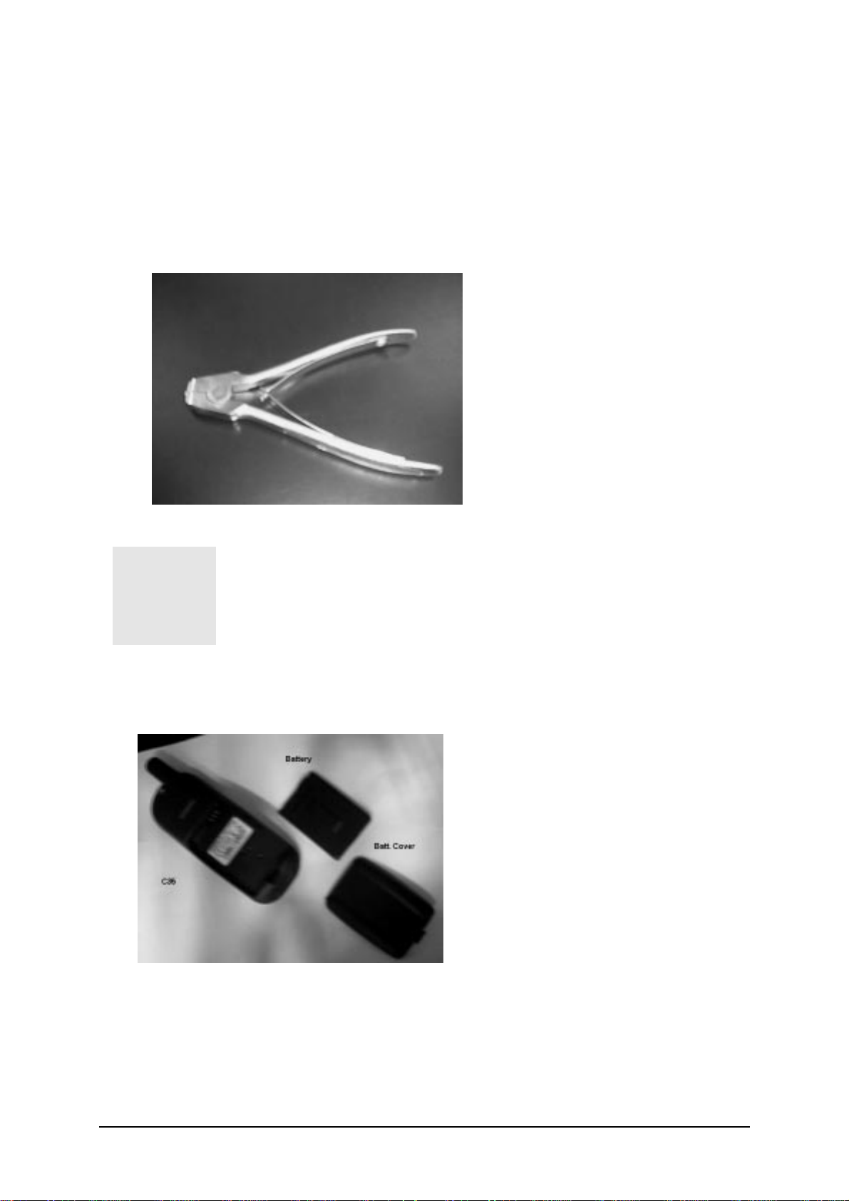
STEP 1:
Remove the battery cover then the batter y as show n in PH OTO 2.4
PHOTO 2.4 DISASSEMBLE C35 – STEP 1
22
V1.0
Page 25
STEP 2:
Open the housing with the openi ng tool and car efully pul l the low er hous ing s ect ion off as
illustrated in PHOTO 2.5
PHOTO 2.5 DISASSEMBLE C35 – STEP 4
STEP 3:
Use the Case Opener c arefull y di sengaged the c atches of the Lower housi ng and U pper
housing to separate the housi ng and the Contr ol Boar d Ass em bly as i n PHOT O 2.6
PHOTO 2.6 DISASSEMBLE C35 – STEP 3
23
V1.0
Page 26
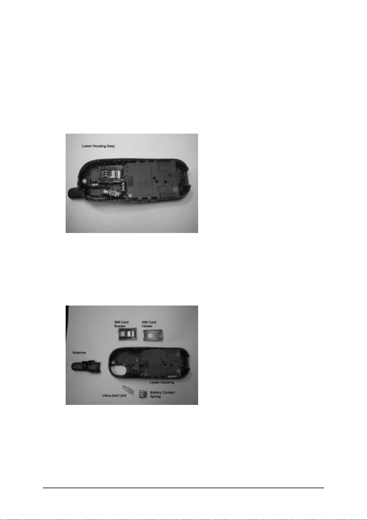
Disassemble/Assemble of the Lower H ousing Assembly
STEP 1:
Open the housing with the openi ng tool and car efully pul l the low er hous ing s ect ion off as
illustrated in PHOTO 2.7
PHOTO 2.7 Lower Housing Assy – STEP 1
STEP 2:
Remove in sequence by hand the SI M Card Holder , SI M Card Reader, Battery C ontact Spr i ng,
Vibra-Aler t U nit and the Antenna as illustrated in PHOTO 2.8
PHOTO 2.8 Disassembly Lower Housing – STEP 2
For Remove/Install the Antenna, watch out for the two catches on the Lower Housing. For install
of the other parts, watch out for the guide notches. For the assembly of the Lower Housing just
reverse the sequenc e for the di sas sem bl y.
24
V1.0
Page 27

Disassemble/Assemble the Control Board Assembly
STEP 1:
Open the housing with the openi ng tool and car efully pul l the low er hous ing s ect ion off as
illustrated in PHOTO 2.9
PHOTO 2.9 Control Boa rd Assy – STEP 1
STEP 2:
Unlock the catches of the Displ ay Module from the Control Board and m ov e the dis play m odule
to the lower part of the PCB. Lift up car efully the r etai ning c l ip of the displ ay c onnector on the
Control Board as illustrated in PHOTO 2.10
PHOTO 2.10 Disassemble Control Boa rd Assy – STEP 2
25
V1.0
Page 28

STEP 3:
Remove the Dis play Module and the Buzzer Sealing from the C ontrol Boar d as illustrated in
PHOTO 2.11
PHOTO 2.11 Disassemble Control Boa rd Assy – STEP 2
For Remove/Install the display m odul e, watc h out for the catches on the di spl ay m odul e and the
guide hole of the PCB. For the assem bl y of the Contr ol Boar d as sem bl y j ust r ev er se the
sequence for the disassem bl y.
26
V1.0
Page 29

Disassemble/Assemble of the Upper Housing Assembly
STEP 1:
Open the housing with the openi ng tool and car efully pul l the low er hous ing s ect ion off as
illustrated in PHOTO 2.12
PHOTO 2.12 Upper Housing Assy – STEP 1
STEP 2:
Remove the Keypad by hand and use a fine poi nt metal tw eezer s to rem ov e the m ic r ophone as
illustrated in PHOTO 2.13
PHOTO 2.13 Disassemble Upper Housing – STEP 2
The loudspeaker is glued to the upper housing section by a foam
covered with glue on both sides. When you remove it, the foam
will be damaged. Please use new loudspeaker for assembling
1
Upper Housing Assembly.
For assembly of a new Upper Housing install a new earphone first, watch out for the orientation.
For install of the other par ts j ust r ev er se the s equence for the dis ass em bly .
27
V1.0
Page 30

Assemble the C35
STEP 1:
Check that the Lower Housing Assembly, Control Board Assembly and Upper Housing
Assembly ar e in good or der . C heck if the Buzzer s eali ng w as i nstal l ed on the C ontrol Boar d.
New Upper and Lower Casing must be used. All
contact pins must not be dirty, damaged or bent!
1
STEP 2:
Place the Control Board Assembly in the Lower Housing Assembly and then place the keypad
on top of the Control Board as illustrated in PHOTO 2.15. You may inse rt a battery in this step to
test that the phone can be switc h on.
If any part is not O.K please replace it with a new
part.
PHOTO 2.15 ASSEMBLE C35 – STEP 2
28
V1.0
Page 31

STEP 3:
Close the device by putting on the Upper casing section as illust rated in PHOTO 2.16 . Hold t he
phone and use both hands to close the casing starting from the catches at the top part near the
antenna, watch out for leaving any finger mar k ing on the di s play sc r een.
Do not place the phone on the
table to close up the housing as
the Antenna may be damage.
1
PHOTO 2.16 ASSEMBLE C35 – STEP 3
STEP 4:
Remove old IMEI label from the old housing using a hair-dryer for re-use of the IMEI label or
paste the new IMEI label supplied for control board replacement. Insert the battery and put back
the battery cover. R eady for tes ting.
ALL CATCHES MUST ENGAGE
COMPLETELY!
PHOTO 2.17 ASSEMBLE C35 – STEP 4
29
V1.0
Page 32

Mobile Software P rogramming
Model before C25 and C35, software used for the mobile are similar except for their differences
in the language group. Customer specific values (e.g. ringing tones etc) are seldom, but there
were some, wer e i ncl uded i n the com m on m obil e softwar e.
C25 and C35 has changed. Ther e is still a common mobile software available which is divided
into language groups. How ever , thi s softwar e does not contai n the s peci fic setti ngs, s uch as
ringing tones, gr eeting tex t, shor t di al li st etc ., r equir ed by the oper ator (s ) or ser vi c e pr ovi der (s ) .
Therefore, it is not unc om mon to hav e som e m enu i tem ( s) di ffer in different variants or ar e not
visible at al l. Thes e setti ngs ar e s tor ed in di fferent memor y area of the mobi l e and will be
activated depending on the custom er s peci fic m odel or v ar iant of the phone by a separ ate test
step during the produc ti on pr oces s.
Due to this separation of common mobile software and customer specific initialization, it is
possible to fulfill the demands of the market requi r i ng cus tom iz ati on and flexibility.
As a consequence the software programming process in the LSO is divided into two diff erent
steps as followed:
1. Software update to actual versi on and appr opr i ate language gr oup
2. Programmi ng of CUS TOMER SPECIFIC INI TIALIZATION
Mobile Software U pdating
The software of the mobile, C35 series, is loaded from a PC directly. Hardware interconnection
between the mobile and the PC is show n i n Fi gur e 2.6
-
-
FIGURE 2.6 C35 SERIES SOFTWARE PROGRAMMING SETUP
Because of the new type of external connector used in C35 (Lumberg type) an additional
adaptor cable between mobile and boot adaptor is required. Table 2.1 listed all the hardware
requirements
30
V1.0
Page 33

If you use the C35 battery dummy, then make sure that the power supply voltage is correctly
adjusted 4.0V & 3A current r ati ng.
Description Part No.
Adaptor-Cable- Bootadaptor , C 35/C35 V30146-A5004-D
Boot Adaptor L24857-F1006-A30
IBM C om patibl e PC – Penti um -
TABLE 2.1 EQUIPMENT LIST FOR SOFTWARE PROGRAMMING.
31
V1.0
Page 34

SOFTWARE IS A DOS-BASED PROGRAM, IT IS
1
1
ADVISABLE TO DO THE SOFTW ARE UPGRADE IN DOS
ENVIRONMENT.
Languague Groups
There are over 20 languages for the C35i series in total. These languages are divided into
groups as follows
C35i / 3508i
Group
1
2
3
4
5
8
Note: Tegic- T9 Input method support in for the languages BOLD.
Languages
English, German, French, It al ian, Dutch
Finnish, Nor w egian, D ani sh.
English
Finnish, Norw egian, Danish
English
Portugese
English, German
Czech, Slovaki an.
English, French, Italian
Bahasan Malay si a, Bahas an I ndones i a.
English2, Chinese Simplified, Chinese Traditional
, German, French, Italian, Dutch,
.
, German,
, Dutch.
French, It alian, Spani s h
, Hungarian, Poli sh, R uss i an, Bulgr i an,
, Arabic, Greek, T urk is h, H ebrew ,
, Swedish,
Swedish,
, Catalan,
.
TABLE 2.2 SOFTWARE LANGUAGE GROUPS.
This information is subject to change!
Contact your Service Manager for the order number of the
right version of mobile softwar e for your m arket.
The mobile softwar e file i s nam ed usi ng thi s c onventi on:
C35_(Version)(LG).E X E
e.g. C3i_0501 Î Version = 05; Language Group = 1
C3i_0506 Î Version = 05; Language Group = 6.
32
V1.0
Page 35

This executable fil e needs a definiti on or i ni t file, nam ed
SWUP.INI
, to define the message
language preferences and the hardw ar e com m uni cati on por t set up.
The content of this file consists of the following tex t:
Language=English
COM=x
Where x is the number that corr esponds to the ser i al por t that i s used, ei ther 1, 2 or 3.
Flow chart 2.1 illustrates the software programming process.
Plug in the Boot
Adaptor to the
PC and Mobile
Connect the AC
adapto r to the
Boot Adaptor
Power up Boo t
Adapto r &
Check L ED
Check AC
Adapto r
Y
Faulty AC
Adapto r
OK
?
OK
?
Powe r up th e PC
in DOS
environment
Execute the
“Mobile S/W”
Error
?
Y
N
N
Check
H/W setup =
S/W settings.
OK
?
Corr e ct setting s.
N
Y
Y
N
Y
Software
upgrading in
progress
Error
?
N
Test Mobile
Take note o f erro r
and repea t
process again
Feedba ck Error
to ICP CD ASC
END
Faulty Bo o t
Adapto r
FLOWCHART 2.1 SOFTWARE PROGRAMMING. PROCESS
33
V1.0
Page 36

Customer Specifi c Initiali zati on
Refer to the Customiz ation Gui de
LSO has to make sure that after repair the
customer gets the mobile with correct variant
specific initialization.
International Mobi le Equipment Identi ty, IMEI
The mobile equipment is uniquely identified by the International Mobile Equipment Identity, IMEI,
which consists of 15 digits. Type approval granted to a type of mobile is allocated 6 digits. The
final assembly code is used to identify the final assembly plant and is assigned with 2 digits. 6
digits have been allocated for the equipment serial number for manufacturer and the last digit is
spare.
C35 series IMEI label i s ac cess i ble by r em ovi ng the batter y. I t is illustrated in Photo 2.18.
PHOTO 2.18 C35 SERIES IIMEI LABEL
For more information about the configuration
tool, refer to Service Information dated 30
April 1999, or contact your Service Manager.
th
Re-use of IM EI label is possibl e by usi ng a hai r - dry er to r em ove the IMEI label .
On this IMEI label, Siemens has also includes the date code for production or service, which
conforms to the industrial standard DIN EN 60062. The date code comprises of 2 characters:
first character denotes the Year and the second character denotes the Month. Fr example, the
IM EI above s how date code
Year Date Code Month Date Code
1999 L December D
2000 M January 1
2001 N F ebr uar y 2
TABLE 2.3 DIN EN 60062 DATE CODE
34
V1.0
M1.
Page 37

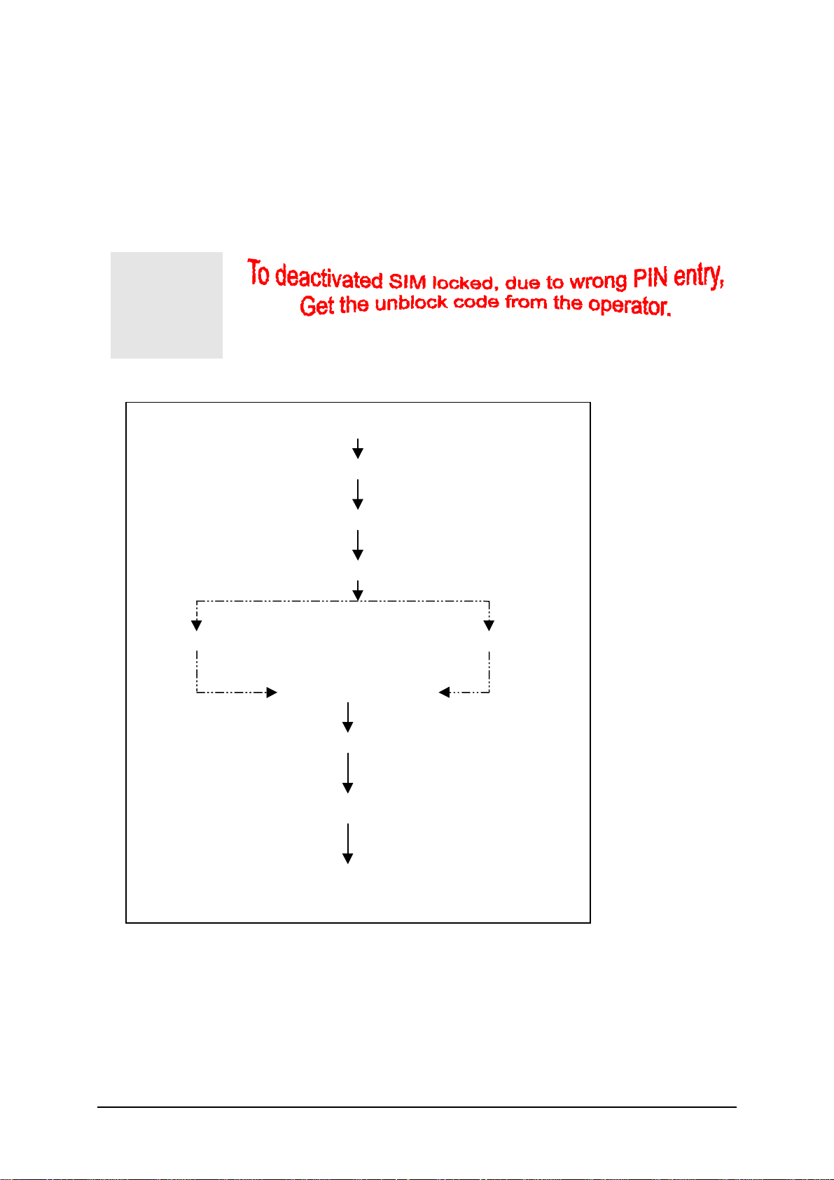
Phone Unblocking
When the phone is disable due to wrong entry of PHONECODE, it can be re-activated by
entering the right unblocking code. This unblocking code is derived from the IMEI number of the
mobile.
The unblocked code, also known as Master Phone Code, has to be entered in the following
forma t:
*#0003*--------#
The Mast er Phone C ode c an be obtai ned by:
1. Fax to Siemens H otli ne i n Ger many
Siemens AG
ICP CD SH
World Service Center, Bocholt, Germany
+49-2871-91-3007
2. Fax to Siemens H otli ne i n Singapor e
Siemens Advanced Engineering Pte Ltd
ICP CD ASC
Ms Ginny Siew
+65-842-6641
3. Internet Solution
A password protected homepage where LSO can enter IMEI number of a disable phone. The
generated Master Code will then be presented for unblocking purpose. This service is offered to
all LSOs.
35
V1.0
Page 38

PHOTO 2.19 INTERNET PAGE
1
PHOTO 2.20 INTERNET PAGE: MASTER PHONE CODE
Contact your Service Manager for more informati on regarding
setting up of the INTERNET SOLUTION & its installation
36
V1.0
procedure, ASC/T002/98.
Page 39

C
hapter
1
1
Siemens Service Equipment
USER MANUAL
Introduction
Every LSO repair i ng Si em ens handset m us t ensur e that the qual i ty s tandar ds ar e obs er ved.
Siemens has developed an automati c testi ng system that will perform all necessary
measurements. This testing system is known as
Siemens Mobile Service Equipment
Using this system vastl y si mpl ifies the repai r of the phones and will make sure that:
1. All possibl e faults ar e detected
2. Set which pass the test will be good enough to return to customer.
Starting from the P35 Series, Siemens will introduce a simpler and faster tes ti ng platform for
testing a repair ed Siem ens m obil e phone. T he testi ng pl atform ar e ei ther base on R &S C MD
53/55 or CTS55 GSM test s et.
There is als o test s oftware under dev elopm ent for test ing w i th the Wavetek 4201S and the 4107
GSM test set.
A Level 2.5 servi ce s oftware i s al so under dev elopm ent for m or e elabor ate tes ti ng for the repai r
for the P35 series mobi le phone.
THE LSO WI LL H AVE TO PURCHASE TH E SY STEM , C HOOSING BETWEEN
THE COM PLETE PACKA GE OR SU B - SET OF I T
A FULLY AUTOMATIC TEST PROCEDURE IS ONLY
POSSIBLE IF THE COMPLETE SYSTEM IS
INSTALLED.
.
Make sure that your CTS fir mw are is V er sion 3.01 or higher . For C MD
55 it must be Version 4.03 and higher. Please check with the S er vice
Info SB_0500 for the C TS/C MD Har dwar e Options.
37
V1.0
Page 40

R&S CMD55 Test Station
R&S CTS55 Test Station
38
V1.0
Page 41

Wavetek 4201S Test Station
Other equipment
One Pentium M MX Window 95/98 PC wi th a s er ial por t to c onnect to the GSM test set through
the PC serial c abl e pr ovi ded for the GSM test set.
One Test SIM card and a fully charged battery for used w it h the m obil e phone m odel .
Additional RF c onnector will be needed for setup using Wavetek 4107 test set and Wavetek
Antenna Coupler.
For LSO Test Station s etup base on the Wavetek 4107 test set, you need a TN C ( m ale) to
SMA(female) c onnector . F or the Wavetek Antenna Coupler, y ou need a TN C ( female) to
SMA(female) c onnector . T he par t num ber for the connector s will be announced soon.
For Wavetek GSM test set For Wavetek Antenna Coupler
39
V1.0
Page 42

Software Installation
Before executing the test software, i t is i mpor tant to ens ur e that the softwar e configur ation
matches that of the hardware set up. Each GSM Tester will have a specific test software. The
test software are name C MD_GO, CTS_GO and for Wavetek test set, CAT4200 respectivel y.
First, copy the ins tal lati on s oftware for the spec i fic GSM tester to a temporary di rec tor y on the
harddisk of the Window PC and then Run the Setup from the first sub di r ec tor y – D i sk 1 for
CMD_GO test software.
After the installation for the test software, RUN the Test software and check the configuration
setting for the Serial port.
40
V1.0
Page 43

Configuring the test software
For each model of the P35 ser ies m obil e phone, Si em ens will distribute the testing configuration
file for the specific test stati on. For test ing the phone, j ust go to the Fi l e menu and s el ect Load
Configuration.
41
V1.0
Page 44

Running the test sequence
1
Make sure that your CTS fir mw are is V er sion 3.01 or higher . For
CMD 55 it must be Version 4.03 and higher . P lease check with the
Service Info S B_0500 for the CTS /CMD Har dware Options.
Insert a Tes t SI M card and a fully charged batter y into the Si em ens m obi l e phone and plac e it
onto the phone holder on the Antenna Coupler . Sw itc h the R F s wi tc h to I N T AN T posi ti on and
select the Start button to run the tes t s equence i n the configur ation fil e.
Follow the ins tr ucti on on the sc r een and sw i tch on the phone. T he m obil e phone will start
Network Sear ch and doi ng Locati on U pdate to the GSM test set through the off-air signal from
Antenna Coupler.
42
V1.0
Page 45

Next, the GSM test set will initial a call to the mobile phone through the Antenna Coupler. Press
the Call key w hen the mobi l e phone r ing, and the GSM test set will start Tx Power
measurements on the GSM and GSM1800 channel speci fied by the configur ati on setti ng.
Next, the GSM test set will end the call to the mobile phone and the s cr een will prompt for
Dialing from the m obi l e phone. At this test s tep, pl ease m ov e the mobi l e phone to the Antenna
Cradle and swi tc h the RF sw i tc h to EXT AN T pos i tion. Onc e the m obil e phone l og to the GSM
test set, dial 1234 and the Send key.
43
V1.0
Page 46

The GSM test set will make Tx Power measurements, Rx BER measurement, Echo Loop test
on the GSM and GSM 1800 c hannel s peci fied by the c onfigurati on s etting. T her e will be 2 Echo
Loop Back test for checking the s peech qual i ty – one for GSM and one for GSM1800. Speak
into the mobile phone w hen prom pted and l i sten the v oic e after appr. 1 s econd and c heck the
speech quality. If not O.K, it may be microphone or the ear phone defective.
The last test is Di s connect C al l from the m obi le phone. Pr es s the End C al l k ey and the tes t
sequence will end.
44
V1.0
Page 47

A measurement r epor t sc r een will show up and a hardcopy can be printed i f a pri nter i s
connected to the PC. To clos e the m easur em ent r epor t sc reen, c l ic k the thi r d button from the
left.
Once the mobile phone pass all the test steps , pleas e m ake a c heck for all the key and the
display. After this w e can c onfirm on the pr oper functioni ng of the mobil e phone after r epair and
return the phone back to the cust omer .
45
V1.0
Page 48

ANNEX A
Cable Specifications
1. PC to NGSM( Pow er Supply )
Depending on the type of serial c onnector that i s used by the PC. T he cabl e l ayout for both
9pins and 25pin are l is ted bel ow :
Computer:
Sub-D 25 pins
TxD Pin 2 RxD Pin 3
RxD Pin 3 TxD Pin 2
RTS Pin 4 DCD Pin 8
DCD Pin 8 RTS Pin 4
CTS Pin 5 DTR Pin 20
DSR Pin 6 DTR Pin 20
DTR Pin 20 CTS Pin 5
DTR Pin 20 DSR Pin 6
GND Pin 7 GND Pin 7
TABLE A.1 D25 TO D25 CONNECTION
Computer:
Sub-D 9 pins
TxD Pin 2 RxD Pin 3
RxD Pin 3 TxD Pin 2
RTS Pin 7 DCD Pin 8
DCD Pin 1 RTS Pin 4
CTS Pin 8 DTR Pin 20
DSR Pin 6 DTR Pin 20
DTR Pin 4 CTS Pin 5
DTR Pin 4 DSR Pin 6
GND Pin 5 GND Pin 7
TABLE A.2 D9 TO D25 CONNECTION
Sub-D 25 pins
Sub-D 25 pins
NGSM:
NGSM:
2. PC to CMD 53 or C T S 55
Depending on the type of connector used for the PC s er i al i nter face, two di fferent type of
cables can be used:
Computer:
Sub-D 25 pins
TxD Pin 2 RxD Pin 2
RxD Pin 3 TxD Pin 3
DSR Pin 6 DTR Pin 4
GND Pin 7 GND Pin 5
DTR Pin 20 DSR Pin 6
CTS Pin 5 RTS Pin 7
RTS Pin 4 CTS Pin 8
TABLE A.3 D25 TO D9 CONNECTION
46
V1.0
CMD / CTS:
Sub-D 9 pins
Page 49

Computer:
Sub-D 9 pins
RxD Pin 3 TxD Pin 2
TxD Pin 2 RxD Pin 3
DSR Pin 6 DTR Pin 4
GND Pin 5 GND Pin 5
DTR Pin 4 DSR Pin 6
CTS Pin 8 RTS Pin 7
RTS Pin 7 CTS Pin 8
TABLE A.4 D9 TO D9 CONNECTION
3. PC to Adaptor Box
CMD / CTS:
Sub-D 9 pins
Computer:
Sub-D 9 pins
Adaptorbox:
Sub-D 9 pins
TxD Pin 2 RxD Pin 3
RxD Pin 3 TxD Pin 2
DTR Pin 4 DSR Pin 6
GND Pin 5 GND Pin 5
DSR Pin 6 DTR Pin 4
RTS Pin 7 CTS Pin 8
CTS Pin 8 RTS Pin 7
TABLE A.5 D9 TO D9 CONNECTION
47
V1.0
Page 50

Jumper Settings of NGSM(Power Supply
1
Internal di p sw i tches of the power s upply , N GSM 32/10, must be set correc tl y to ens ure
proper comm uni cati on between PC and the N GSM. These switches are s et up by Si em ens
and tested before delivery , hence i t i s not nec ess ar y to change i t nor m al ly .
These switc hes ar e l ocated under the l eft side of the cover of the NGSM.
Position OFF ON OFF OFF ON OFF OFF ON
Switch No. 1 2 3 4 5 6 7 8
TABLE A.6 SWITCH SETTINGS
Test SIM card Informati on
For testing pur poses , in c om binati on w i th the R ohde & Schw ar z GSM tester, CM D or C TS, i t i s
mandatory to use the encl osed tes t SIM card.
If you do not use this test SIM card, you will encounter difficulties in getting cor rec t m easur em ent
for the Bit Error Rate.
When the SIM card simulation is set to ‘1’ in the I NI file, then this
test SIM card is not needed at all
There are two di fferent PIN number s st or ed in the SIM card. The PINs and their respecti v e
Master -P I N ar e:
PIN 1 12 34
Master-PIN 1 76 54 32 10
PIN 2 56 78
Master-PIN 2 98 76 54 32
TABLE A.7 D25 TO D25 CONNECTION
48
V1.0
Page 51

ANNEX B
0
Service Equipment List
All purchases of jigs, tools and test equipment must be order directly from Siemens Germany. Attach the
standard form with your purchase order and send it to ICP CD SL and ICP CD ST.
Pos.
No.
Special testequipment for use with CMD 53
1 GSM T ester CMD 53 incl. Options B 1 , B4, B30
RF-Switch F30032-P27-A1
11
Powersupply for RF-Switch V24851-Z2607-A1
12
13
RF-cable SMA(m)
14
RF-cable SMA(m)
15
RF-cable SMA(m)
Special testequipment for use with CTS 55
10 GSM-Tester CTS 55 incl. Options B 1 ,B7,K6,K9,K18
RF-Switch F30032-P27-A1
11
Powersupply for RF-Switch V24851-Z2607-A1
12
13
RF-cable SMA(m)
14
RF-cable SMA(m)
15
RF-cable SMA(m)
Testequipment for use with CTS 55 or CMD 53
Test-SIM-Card (plug-in type) F30032-P2-A1
16
17
RS 232 cable PC
Printer incl. parallel cable F30032-P7-A1
21
22 Test jig incl. aerial coupler “new”
23
Connector N
User manual test software CMD / CTS F30032-P13-A1
24
Disk with test software CMD / CTS F30032-P19-A1
25
Antenna Cradle C35/S35/M35 L36880-N4001-A11
↔
FME(m)
↔
↔
↔
↔
↔
↔
↔
Name Siemens
FME(f)
SMA(m)
SMA(f)
FME(f)
SMA(m)
SMA(f)
CMD / CTS (9pins.)
F30032-P30-A1
F30032-P31-A1
F30032-P32-A1
F30032-P24-A1
F30032-P30-A1
F30032-P31-A1
F30032-P32-A1
F30032-P11-A1
Partnumber
F30032-P1-A1
F30032-P3-A1
F30032-P8-A1
Order?
(
=Yes)
:
:
For use with C25/ C35 SW Upgrade Station
Boot Adapter incl. AC-Adapter, serial cable & Mobile
26
connection cable. Need nos 41 for C35.
Adapter-Cable-Bootadapter C25/C35 V30146-A5004-D
43
Opening -Tools for use with C25/C35
Case opener C35
44
Battery Analyser
45 CADEX Tester C7000
Universal Adapter F30032-P59-A1
46
TABLE B.1 SERVICE EQUIPMENT ORDER FORM
For detail inform ation, contact your S er vi ce Manager
49
V1.0
L24857-F1006-A30
F30032-P46-A1
F30032-P49-A1
Page 52

C
hapter
/HYHO 5HSDLU 'RFXPHQW
Introduction
The C/M/S35 product family consists of 5 different dualband handsets (GSM-900 and GSM-
1800), which can easily be distinguished from the second block of the part number printed on
the IMEI label. There also exist Asian variants of C/M/S35 named 3508 / 3518 / 3568
respectivel y. Al l i nform ation bel ow als o appl ies to the Asi an var i ants unl ess other w is e noted.
Partnumber on IMEI label:
1) C 35 / 3508: S30880-S4000-Xxxx
2) C 35i / 3508i: S30880-S4050-Xxxx
Same as C35 / 3508 but wit h additi onal WAP and fax/data capabilities
3) M35 / 3518: S30880-S4200-Xxxx
4) M35i / 3518i: S30880-S4250-Xxxx
Same as M35 / 3518 but w i th addi tional WAP and fax/data capabilities
5) S35i / 3568i : S30880-S4100-Xxxx
This manual is intended to help you carry out repairs on level 2.5, meaning limited component
repairs. F ai lur e hi ghl i ghts ar e doc umented and s houl d be r epair ed i n the l ocal w or ks hops .
It must be noted that all repairs have to be carried out in an environment set up according to the
ESD (Electr ostati c Di sc har ge Sensi ti ve D evi c es) r egulati ons defined in i nternati onal standar ds .
All repairs have to be carr ied out in an envir onm ent set up
according to ESD r egulations defined in inter national standards.
1
50
V1.0
ESD procedure is available from your Service Manager. As k for
ASC/T001/98
Page 53

Fault code listed mu st be u sed for LS O r epor tin g pu r pose.
Fault Descr ipti on Fault Code Part Number
If you have any questions regarding the repair procedures or spare parts do not hesitate to
contact our technical suppor t team in Kam p- Li ntfort, Germ any:
Tel.: +49 2842 95 4666
Fax: +49 2842 95 4302
e-mail: dom i nik .sc hnoor @kl f.siem ens.de
This manual i s i ntended to hel p you c ar ry out r epair on Lev el 2.5, i.e. l i m it ed com ponent r epair .
Failure highl i ghted in thi s docum ent shoul d be r epai r ed in the l ocal w or kshop.
51
V1.0
Page 54

$QWHQQD &RQQHFWRU
Af fect ed U ni ts
Type : C/M/S35
Af f ect ed IMEIs / Dat e Co des :
Af f ect ed SW - Ver s i o n s :
Fault Code for LSO reporting: 3ANC
Fault Description
Fault Symptoms for customers:
Fault Symptom on GSM-Tester:
Component Information
All / All
All
Network Sear ch w hen usi ng the exter nal antenna ( car k it)
No location update possi bl e on exter nal antenna ( car ki t)
Output power problem s on the ex ter nal antenna
No location update possi bl e
The Antenna Connector is a m echani cal s wi tc h oper ated by the R F plug of a cark i t or , for testi ng
purposes, of an RF cli p.
Normall y the R F si gnal goes to and c omes from the inter nal antenna. Whenever an RF pl ug is
plugged into the antenna connector the c onnecti on to the i nternal antenna i s opened and the
connection to the external antenna soc ket i s m ade. See dr aw i ng below.
From
Power
Amplifier/
To / From
Internal
Antenna
52
V1.0
Page 55

3ULRULW\
_
Repair Documentation
Description of procedure:
DIAGNOSIS
REPAIR BY COMPONENT CHANGE
........ Mandatory
........ Repair
........ Optional
........ Not Yet Defined
Check the output power of the handset wi th the LSO tes tpr ogr am .
Especially w atc h the exter nal antenna pow er!
Use hot air blow er to r em ove defectiv e connector
Avoid excessi ve heat!
Watch surrounding components!
Resolder new c onnector afterw ards .
REPAIR BY SW-BOOTING
Not possible!
TEST
Retest handset after repair as des cr i bed above.
List o f need ed material
COMPONENTS
X35 antenna connector
Attention: This is not the same connector as C25/S25 !!!
Part-Number: L36334-Z93-C272
53
V1.0
Page 56

JIGS AND TOOLS
Hot Air Blower
Soldering I r on
SPECIAL TOOLS
None
WORKING MATERIALS
Desolder Wick / Braid
Solder
'UDZLQJV
Figure 1: X35 Board Antenna C onnector Si de ( Top Vi ew )
54
V1.0
Page 57

5LQJHU
Af fect ed U ni ts
Type : C/M/S35
Af f ect ed IMEIs / Dat e Co des :
Af f ect ed SW - Ver s i o n s :
Fault Code for LSO reporting: 3RIN
Fault Description
Fault Symptoms for customers:
Fault Symptom on GSM-Tester:
Priority :
_
........ Mandatory
........ Repair
........ Optional
........ Not Yet Defined
All / All
All
Problems w ith the hands et r i nger. N o r i nger tone audibl e.
Handset fails ringer tes t.
55
V1.0
Page 58

Repair Documentation
Description of procedure:
DIAGNOSIS
Visually chec k the r i nger . Watch for physical dam age or dr y j oints .
REPAIR BY COMPONENT CHANGE
Resolder dry sol der i ng joi nts.
If the ringer is phys i cal ly dam aged use hot ai r bl ower or w ic k to r em ove defectiv e
connector.
Avoid excessi ve heat!
Watch surrounding components!
Resolder new r i nger afterwar ds .
REPAIR BY SW-BOOTING
Not possible!
TEST
Retest handset after repair .
List o f need ed material
COMPONENTS
Ringer P35:
Part-Num ber : L36178-Z2-C26
JIGS AND TOOLS
Hot Air Blower
Soldering I r on
56
V1.0
Page 59

SPECIAL TOOLS
None
WORKING MATERIALS
Desolder Wick / Braid
Solder
Flux
Drawings
Figure 1: X35 Board R inger Si de
Figure 2: X35 Ri nger ( B800) Pl acem ent ( T op View )
57
V1.0
Page 60

%RWWRP &RQQHFWRU /XPEHUJ
Af fect ed U ni ts
Type : C/M/S35
Af f ect ed IMEIs / Dat e Co des :
Af f ect ed SW - Ver s i o n s :
Fault Code for LSO reporting: 3LUC
Fault Description
Fault Symptoms for customers:
Fault Symptom on GSM-Tester:
All / All
All
Charging probl em s .
Problems w i th exter nal l oudspeak er or m i cr ophone w hen
using a car ki t.
Problems w ith ac ces sor i es c onnected at the bottom
connector.
Problems w ith SW booting.
This problem c annot be detected w it h a GSM-Tester.
Priority :
_
........ Mandatory
........ Repair
........ Optional
........ Not Yet Defined
58
V1.0
Page 61

Repair Documentation
Description of procedure
DIAGNOSIS
Visually chec k the bottom c onnector . Watch for dry joints !
REPAIR BY COMPONENT CHANGE
Use hot air blow er r em ove defectiv e bottom c onnector .
Avoid excessi ve heat!
Watch surrounding components!
Resolder new bottom c onnector afterwar ds .
REPAIR BY SW-BOOTING
Not possible!
TEST
Retest handset after repair .
List o f need ed material:
COMPONENTS
Bottom Connector X35
Part-Num ber : L36334-Z93-C262
JIGS AND TOOLS
Hot Air Blower
Soldering I r on
SPECIAL TOOLS
None
59
V1.0
Page 62

WORKING MATERIALS
Desolder Wick / Braid
Solder
Drawings
Figure 1: X35 Board Bottom C onnector Si de
Figure 2: X35 Bottom C onnector Pl acem ent ( T op View )
Pin 12
Pin 1
Table 1: X35 Bottom Connector Pi n D escr i pti on
60
V1.0
Page 63

Name IN/OUT Notes
Pin
1GND
2 SB I/O Charger c oding and
charger contr ol.
3 POWER I Charging Current
4 FBatt+ O Power supply for the
accessories.
5 TX O Serial interface
6 RX I Serial interface
7 ZUB_CLK I/O Clock line for
accessory bus
Use as DTC I n data
operation
8 ZUB_DATA I/O Data line for
accessory bus.
Use as CTS i n data
operation
9 GND_MIC For external
microphone
10 HF_MIC I External microphone
11 AUDO O Trigger for exter nal
loudspeaker
12 GNDA For external
loudspeaker
61
V1.0
Page 64

'LVSOD\ &RQQHFWRU
Af fect ed U ni ts
Type : C/M/S 35
Af f ect ed IMEIs / Dat e Co des :
Af f ect ed SW - Ver s i o n s :
Fault Code for LSO reporting: 3DIC
Fault Description
Fault Symptoms for customers:
Fault Symptom on GSM-Tester:
3ULRULW\
_
........ Mandatory
........ Repair
All / All
All
Display pr obl ems , l i ke m i ss ing l i nes or col um ns on the
LCD or displ ay c ontr ast pr obl em s.
Display test fails.
........ Optional
........ Not Yet Defined
62
V1.0
Page 65

Repair Documentation
Description of procedure:
DIAGNOSIS
Visually chec k the s tatus of the display connec tor. Watch for oxidation
and dry solder j oi nts.
Mechanic all y c heck the openi ng / cl osi ng m echani sm .
REPAIR BY COMPONENT CHANGE
Use hot air to r emov e defective c onnector
Avoid excessi ve heat!
Watch surrounding components!!
Resolder new c onnector afterw ards
REPAIR BY SW-BOOTING
TEST
Not possible!
Retest handset after repair .
63
V1.0
Page 66

List o f need ed material
COMPONENTS DISPLAY CONNECTOR
Part-Number: L36195-Z26-C629
JIGS AND TOOLS
Soldering I r on
Hot Air Blower
SPECIAL TOOLS
None
WORKING MATERIALS
Desolder Wick / Braid
Solder
64
V1.0
Page 67

Drawings
Figure 1: X35 board di s play connec tor si de
Figure 2: X35 displ ay c onnector pl acem ent ( T op View )
65
V1.0
Page 68

.H\ERDUG
Af fect ed U ni ts
Type : C/M/S 35
/('V
Af f ect ed IMEIs / Dat e Co des :
Af f ect ed SW - Ver s i o n s :
Fault Code for LSO reporting: 3LED
Fault Description
Fault Symptoms for customers:
Fault Symptom on GSM-Tester:
Priority :
_
........ Mandatory
........ Repair
All / All
All
Keyboard Ill um i nation not w or ki ng.
This fault cannot be detected wi th a GSM-Tester
........ Optional
........ Not Yet Defined
66
V1.0
Page 69

Repair Documentation
Description of procedure:
DIAGNOSIS
Use the diode test function of a multi m eter to chec k the st atus of the
diode.
The typical vol tage dr op on the di ode is 1.7V w hen testi ng the di ode
function with the multi m eter .
REPAIR BY COMPONENT CHANGE
Use solderi ng i ron to r em ov e defective di ode
Avoid excessi ve heat!
Watch surrounding components!
Resolder new di ode afterwar ds .
REPAIR BY SW-BOOTING
TEST
List o f need ed material
COMPONENTS
JIGS AND TOOLS
Not possible!
Retest handset after repair .
LED keyboard X35
Part-Num ber : L36840-L2031-D670
Hot Air Blower
Soldering I r on
67
V1.0
Page 70

SPECIAL TOOLS
None
WORKING MATERIALS
Desolder Wick / Braid
Solder
Drawings
Figure 1: X35 board key boar d LED Si de
Figure 2: X35 keyboar d LED pl acem ent and pol ar i ty (t op vi ew )
68
V1.0
Page 71

'LVSOD\ /('V
Af fect ed U ni ts
Type : C/M/S 35
Af f ect ed IMEIs / Dat e Co des :
Af f ect ed SW - Ver s i o n s :
Fault Code for LSO reporting: 3LED
Fault Description
Fault Symptoms for customers:
Fault Symptom on GSM-Tester:
Priority :
_
........ Mandatory
........ Repair
All / All
All
Display I l l um inati on not w or ki ng.
This fault cannot be detected wi th a GSM-Tester
........ Optional
........ Not Yet Defined
69
V1.0
Page 72

Repair Documentation
Description of procedure:
DIAGNOSIS
Use the diode test function of a multi m eter to chec k the st atus of the
diode.
The typical vol tage dr op on the di ode is 1.7V w hen testi ng the di ode
function with the multi m eter .
Attention: There are two different types of display LEDs, one for
C/M35 an d o ne f o r S35! Al s o t hey use dif f erent p l acement locat i o n,
see draw i n g s 1 and 3.
REPAIR BY COMPONENT CHANGE
Use solderi ng i ron to r em ov e defective di ode
Avoid excessi ve heat!
Watch surrounding components!
Resolder new di ode afterwar ds .
REPAIR BY SW-BOOTING
Not possible!
TEST
Retest handset after repair .
List o f need ed material
COMPONENTS
Display LED S35
Part-Num ber : L36840Display LED C/M35
Part-Num ber: L36840-
JIGS AND TOOLS
L2048-
L2047
D670
-D670
Hot Air Blower
Soldering I r on
70
V1.0
Page 73

SPECIAL TOOLS
None
WORKING MATERIALS
Desolder Wick / Braid
Solder
Drawings
Figure 1: C/M35 board display LED Si de
Figure 2: C/M35 board display LED pl acem ent and pol ar i ty
71
V1.0
Page 74

Figure 3: S35 board di spl ay LED si de
Figure 4: S35 board di s play LED plac em ent and pol ar it y
72
V1.0
Page 75

,QIUDUHG 'LRGHV
Af fect ed U ni ts
Type : S 35
Af f ect ed I MEIs / Dat e Co des :
Af f ect ed SW - Ver s i o n s :
Fault Code for LSO reporting: 3INF
Fault Description
Fault Symptoms for customers:
Fault Symptom on GSM-Tester:
Priority :
_
........ Mandatory
........ Repair
All / All
All
No infrared connecti on possi bl e.
This fault cannot be detected wi th a GSM-Tester.
V1.0
........ Optional
........ Not Yet Defined
73
Page 76

Repair Documentation
Description of procedure:
DIAGNOSIS
Visually chec k the s tatus of the Ir D a m odule. Watch for dry solder j oints .
Use a reference infrared por t ( eg. from a notebook) to c heck the I r D a
function. If the notebook recognizes the S35, the infrar ed function i s ok .
REPAIR BY COMPONENT CHANGE
Use hot air to r emov e defective i nfrar ed modul e.
Avoid excessi ve heat!
Watch surrounding components!!
Resolder new m odul e afterwar ds
REPAIR BY SW-BOOTING
TEST
Not possible!
Retest handset after repair .
74
V1.0
Page 77

List o f need ed material
COMPONENTS INFRARED MODULE S35
Part-Num ber : L36810-U6030-D670
JIGS AND TOOLS
Soldering I r on
Hot Air Blower
SPECIAL TOOLS
None
WORKING MATERIALS
Desolder Wick / Braid
Solder
75
Page 78

ANNEX C
PC Adaptor Cable & A ccessories C35
Adapter Cable E-Box-PC
L36880-N3101-A112
Belt C lip
L36880-N4001-A113
Adapter Cable PC-Mobilephone
L36880-N3101-A102
VDA Adaptercable
L36880-N4001-A121
Car Kit Portable Handsfree Set
L36880-N3015-A117
12 V
Car Kit Portable Handsfree Microphone
L36254-Z6-C75
Microphone Accessories Kit
L36158-A98-C6
Car Charger Cable 10,8-24V
L36880-N4001-A108
Headset
L36880-N4001-A123
Car Holder
L36158-A24-C25
76
Page 79

77
Page 80

Power Plug for C35, M35 , S35
L36280-Z4-C325
L36280-Z4-C321
Travel Charger 90-240 V Travel Charger 90-240V
L36880-N4001-A103 L36880-N4001-A104
L36280-Z4-C324
L36280-Z4-C323
L36280-Z4-
Power Plug
Desktop Charger
L36880-N4001-A102
Eur UK
78
Page 81

Car installati on kit Ratio uni t C35, M35 & S35
\
Cradle Comfort
L36158-A37-B1
Handsfree Microphone
L36880-N4001-A116
Handset
L36880-N3015-A123
Connection Box
Ratio
Phone In Adapter
L36880-N3015-A137
1RW LQFOXGHG LQ RXU 6WDQGDUG 'HOOLYU
79
Con. Cable Battery
Comfort
L36146-A2053-D
Page 82

Car installati on kit hands free unit C35, M35, S35
Phone In Adaptor
L36880-N3015-A137
Con. Cable Battery Comfort
L36146-A4013-D
Fuses 3A
1,8m
Connection Box
L36880-S2001-A100
Handsfree Loudspeaker
L36104-F3090-X902
OR
Radio Mute black
Battery red
Battery Ground brown
Ignition violet
Handsfree Microphone
L36254-Z6-C76
3m
Handset
L36880-N3015-A123
1RW LQFOXGHG LQ RXU 6WDQGDUG 'HOOLYU\ 3URJUDP
Cradle Comfort
L36158-A37-B1
80
Page 83

Carkit i nstallation kit hand free uni t Professional C35, M35, S35
Handsfree Loudspaker
L36104-F3090-X901
Con. Cable Battery
L36146-A1030-D
Radio Mute black
Fuses 3A
1,9m
3m
Handfree Microphone
L36254-Z6-C63
Lights Dimmer yellow
Automatic A n tenna
Battery red
Battery ground brown
white
Adapter Cable E-Box-PC
L36880-N3101-A112
Handset
L36880-N3015-
Not included in our Standard
Push to ta lk
cable
Connection Box engl.
L36880-N3101-A110
Cradle Comfort
L36158-A37-B1
81
Page 84

Carkit i nstallation Comfort GPS C35, M35, S35
Combi Antenna GPS
L36851-Z1901-A46
Handset
L36880-N3015-
Car Cradle Telematic
L36158-A37-B6
Handsfree Loudspeaker
L36104-F3090-X902
Con. Pox
Crash Sensor
L36880-N4001-A115
Connection Pox GPS
L36880-S4001-A4
Antenna
O
1RW LQFOXGHG LQ RXU 6WDQGDUG
82
Handsfree Microphone
L36880-N4001-A116
Con. Cable Battery
L36146-A2053-D
Phone In Adapter
L36880-N3015-A137
Page 85

PC Adaptar Cable & A ccessory C35, M35, S35
Adaptor Cable E-Box -PC
L36880-N3101-A112
Belt Clip
L36880-N4001-A113
Adapter Cable PC-Mobilephone
L36880-N3101-A102
VDA Adaptercable
L36880-N4001-A121
Car Kit Portable Handsfree Set
L36880-N3015-A117
12 V
Car Kit Portable Handsfree Microphone
L36254-Z6-C75
Microphone Accessories Kit
L36158-A98-C6
Headset
L36880-N4001-A123
Car Charger cable 10, 8 – 24V
L36880-N4001-A108
Car Holder
L36158-A24-C25
83
Page 86

References:
1. M ouly M. & Pautet M-B. (1992)
The GSM System for Mobile Communications, A
comprehensive overview of the European Digital Cellular Systems
Published by authors.
2. Scourias, J
Overview of t he Global Syst em for Mobile Communicat ions
of Waterloo: Published by author.
3. - (1998)
GSM Introduction
Published by Wavetek Wireless Communication
Division.
4. Barnes, N
SIM Application Toolkit
5. M ehrotra A, (1994),
Cellular Radio Analog and Digital System
, Article by author on ETSI Website.
, Artech House Inc,
USA.
6. IrDA(Infrared Data Association),
Version 1.1
, October 15, 1995.
Serial Infrared Phys ical Layer Link Specification,
France:
Univ ersity
Disclai mer: Thi s content is subjected to change without notic e.
Copyright 2000 Siemens Advanced Engineering Pte Ltd
ICP CD Asia Service Center,
164, Kallang Way, #04-22, Kolam Ayer Industrial Estate, Singapore 349248
Author: Tan Guan San.
Phone +65-8454822 • Fax +65-8426641
First Print: A pril, 00
Revised Print:
The reproduction and transmission of this document to unauthorized parties is not permitted
without written authority. Offender will be liable for damages.
84
 Loading...