

Page 1
Information and Communication
Communication Devices
C10 / C11
Level 2.5
Repair Documentation
V 1.0
V1.0 Page 1 of 33 ICP CD ST
D. Schnoor
08/98
Page 2
Information and Communication
Communication Devices
1Introduction
The product familiy C1x consists of C10 (GSM-900), C11 (GSM-1800) and C12
(GSM-1900). This manual only deals with the C10 and the C11. If parts or repairs are
identical instead of C10 and C11 only C1x is mentioned.
This manual is intended to help you carry out repairs on level 2.5, meaning limited
component repairs. Failure highlights are documented and should be repaired in the local
workshops.
It must be noted that all repairs have to be carried out in an environment set up according to
the ESD (Electrostatic Discharge Sensitive Devices) regulations defined in international
standards.
If you have any questions regarding the repair procedures or spare parts do not hesitate to
contact our technical support team in Kamp-Lintfort, Germany:
Tel.: +49 2842 95 4666
Fax: +49 2842 95 4302
e-mail: dominik.schnoor@klf.siemens.de
V1.0 Page 2 of 33 ICP CD ST
D. Schnoor
08/98
Page 3

Information and Communication
Communication Devices
Table of Contents:
1 INTRODUCTION................................................................................................................................................2
2 13 MHZ OSCILLATOR
...................................................................................................................................................................................4
3 FUSE 1A
...................................................................................................................................................................................9
4 RINGER CONNECTOR
.................................................................................................................................................................................15
5 MOLEX CONNECTOR
.................................................................................................................................................................................21
6 18ΜH COIL
.................................................................................................................................................................................25
7 ANTENNA SPRING
.................................................................................................................................................................................30
V1.0 Page 3 of 33 ICP CD ST
D. Schnoor
08/98
Page 4

Information and Communication
Communication Devices
213 MHz oscillator
2.1Affected Units
2.1.1Type: C10, C11 (different components!)
2.1.2Affected IMEIs / Date Codes: All / All
2.1.3Affected SW-Versions: All
2.1.4Fault Code for LSO reporting: C10: 3OSC
C11: 3VCX
2.2Fault Description
2.2.1Fault Symptoms for customers:
Network Search
Handset not logging into network
2.2.2Fault Symptom on GSM-Tester:
Frequency error in synchronized mode >90 Hz
No location update possible
The Oscillator is responsible for generating the 13 MHz reference frequency of the handset.
If it is defective, the handset cannot synchronize to the base station anymore.
V1.0 Page 4 of 33 ICP CD ST
D. Schnoor
08/98
Page 5

Information and Communication
Communication Devices
2.3Priority:
........ Mandatory
........ Repair
........ Optional
........ Not Yet Defined
2.4Repair Documentation
2.4.1Description of procedure:
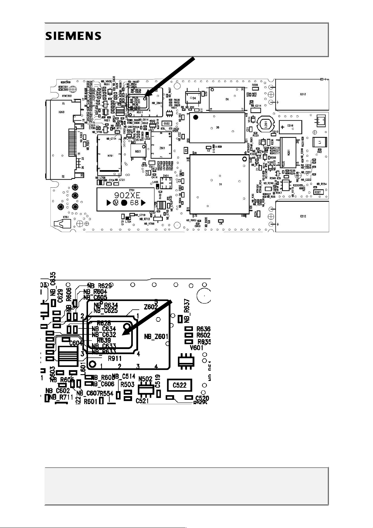
For the C10 three different 13MHz oscillators can be used: A TCXO, a
VCXO (Both are called Z601 in the placement diagram) and a normal
13 MHz oscillator (Z602).
The production status handsets all have a normal 13 MHz oscillator
placed, no VCXO or TCXO is used.
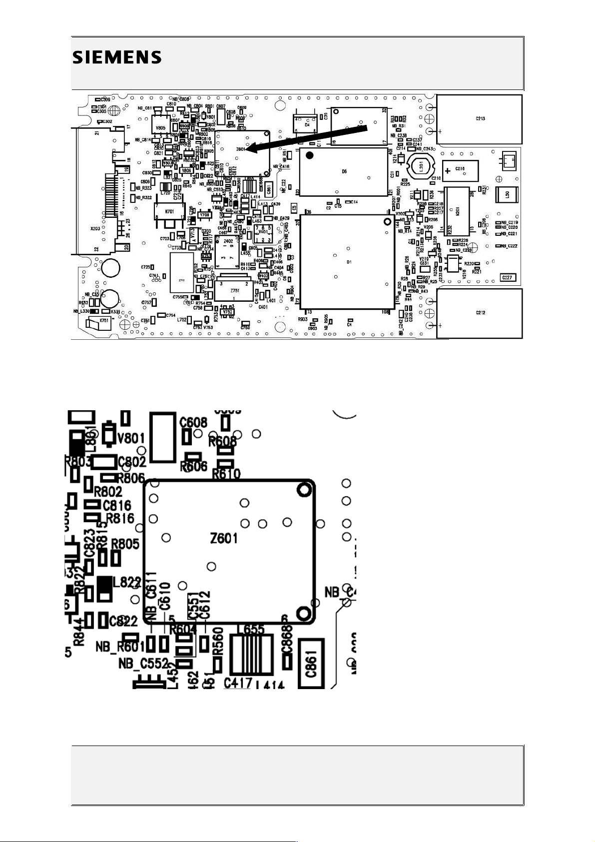
For the C11 only a VCXO is used.
2.4.1.1Diagnosis
Check the output frequency of the oscillator using the level-2 testing
program for C10 / C11.
Set the „Simulator“ option in the S611.INI file to 0 and restart
the program. Start the test. When the program says „Check power and
phase of external antenna with your GSM-Tester“, switch the CMD to
„LOCAL“ mode and enter the „MODULE TEST“.
On the CMD display you can see the frequency error of the handset.
(Make sure that the CMD is on channel 124, power level 5!)
If the frequency error is higher than 2kHz, the oscillator has to be
replaced.
2.4.1.2Repair by component change
Use hot air blower to remove defective oscillator.
Avoid excessive heat!
Watch surrounding components!
Resolder new oscillator afterwards.
2.4.1.3Repair by SW-Booting
V1.0 Page 5 of 33 ICP CD ST
D. Schnoor
08/98
Page 6

Information and Communication
Communication Devices
Not possible!
2.4.1.4Test
Retest handset after repair as described above.
The frequency error must now be < 2kHz.
2.4.2List of needed material
2.4.2.1Components
C10: 13 MHz oscillator
Part-Number: L36145-F220-Y2
C11: VCXO
Part-Number: L36145-G300-Y21
2.4.2.2 Jigs and Tools
Hot Air Blower
Soldering Iron
2.4.2.3Special Tools
None
2.4.2.4Working materials
Desolder Wick / Braid
Solder
2.4.3Drawings
V1.0 Page 6 of 33 ICP CD ST
D. Schnoor
08/98
Page 7
Information and Communication
Communication Devices
V1.0 Page 7 of 33 ICP CD ST
D. Schnoor
08/98
Figure 1: C10 Board 13 MHz Oscillator Side (Top View)
Figure 2: C10 13 MHz Oscillator Placement (Z602) (Top View)
Page 8
Information and Communication
Communication Devices
V1.0 Page 8 of 33 ICP CD ST
D. Schnoor
08/98
Figure 3: C11 Board VCXO Side (Top View)
Figure 4: C11 VCXO (Z601) Placement (Top View)
Page 9

Information and Communication
Communication Devices
3Fuse 1A
3.1Affected Units
3.1.1Type: C10, C11
3.1.2Affected IMEIs / Date Codes: All / All
3.1.3Affected SW-Versions: All
3.1.4Fault Code for LSO reporting: C10, C11: 3FU1
3.2Fault Description
3.2.1Fault Symptoms for customers:
Battery charging not possible
3.2.2Fault Symptom on GSM-Tester:
This fault cannot be detected with a GSM-Tester
V1.0 Page 9 of 33 ICP CD ST
D. Schnoor
08/98
Page 10

Information and Communication
Communication Devices
3.3Priority:
........ Mandatory
........ Repair
........ Optional
........ Not Yet Defined
3.4Repair Documentation
3.4.1Description of procedure:
3.4.1.1Diagnosis
Check the status of the fuse by measuring its resistance with
a multimeter. The fuse is defective if the resistance is higher than 10
ohms.
3.4.1.2Repair by component change
Use soldering iron to remove defective fuse.
Avoid excessive heat!
Watch surrounding components!
Resolder new fuse afterwards.
3.4.1.3Repair by SW-Booting
Not possible!
3.4.1.4Test
Retest handset after repair as described above.
V1.0 Page 10 of 33 ICP CD ST
D. Schnoor
08/98
Page 11

Information and Communication
Communication Devices
The resistance must now be close to zero.
3.4.2List of needed material
3.4.2.1Components
Fuse
Part-Number: L36145-A820-Y7
3.4.2.2Jigs and Tools
Soldering Iron
3.4.2.3Special Tools
Multimeter
3.4.2.4Working materials
Desolder Wick / Braid
Solder
V1.0 Page 11 of 33 ICP CD ST
D. Schnoor
08/98
Page 12

Information and Communication
Communication Devices
3.4.3Drawings
V1.0 Page 12 of 33 ICP CD ST
D. Schnoor
08/98
Figure 1: C10 Board 1A Fuse Side
Figure 2: C10 1A Fuse (F901) Placement (Top View)
Page 13

Information and Communication
Communication Devices
V1.0 Page 13 of 33 ICP CD ST
D. Schnoor
08/98
Page 14

Information and Communication
Communication Devices
V1.0 Page 14 of 33 ICP CD ST
D. Schnoor
08/98
Figure 3: C11 Board 1A Fuse Side
Figure 4: C11 1A Fuse (F901) Placement (Top View)
Page 15

Information and Communication
Communication Devices
4Ringer Connector
4.1Affected Units
4.1.1Type: C10, C11
4.1.2Affected IMEIs / Date Codes: All / All
4.1.3Affected SW-Versions: All
4.1.4 Fault Code for LSO reporting: C10, C11: 3RIC
4.2Fault Description
4.2.1Fault Symptoms for customers:
Problems with the handset ringer. No ringer tone
audible.
4.2.2Fault Symptom on GSM-Tester:
Handset fails ringer test.
4.3Priority:
........ Mandatory
........ Repair
........ Optional
........ Not Yet Defined
V1.0 Page 15 of 33 ICP CD ST
D. Schnoor
08/98
Page 16

Information and Communication
Communication Devices
4.4Repair Documentation
4.4.1Description of procedure:
The connector B1 is connecting the main board of the C1x with the piezo
ringer through a two pin cable.
4.4.1.1Diagnosis
Visually check the connector. Watch for bent contacts and dry joints.
4.4.1.2Repair by component change
Resolder dry soldering joints.
If the connector is physically damaged use hot air blower or wick to remove
defective connector.
Avoid excessive heat!
Watch surrounding components!
Resolder new connector afterwards.
4.4.1.3Repair by SW-Booting
Not possible!
4.4.1.4Test
Retest handset after repair.
V1.0 Page 16 of 33 ICP CD ST
D. Schnoor
08/98
Page 17

Information and Communication
Communication Devices
4.4.2List of needed material
4.4.2.1Components
Ringer Connector C1x:
Part-Number: L36334-Z97-C43
4.4.2.2Jigs and Tools
Hot Air Blower
Soldering Iron
4.4.2.3Special Tools
None
4.4.2.4Working materials
Desolder Wick / Braid
Solder
Flux
V1.0 Page 17 of 33 ICP CD ST
D. Schnoor
08/98
Page 18

Information and Communication
Communication Devices
4.4.3Drawings
V1.0 Page 18 of 33 ICP CD ST
D. Schnoor
08/98
Figure 1: C10 Board Ringer Connector Side
Page 19

Information and Communication
Communication Devices
V1.0 Page 19 of 33 ICP CD ST
D. Schnoor
08/98
Figure 2: C10 Ringer Connector Placement (Top View)
Figure 3: C11 Board Ringer Connector Side
Page 20

Information and Communication
Communication Devices
V1.0 Page 20 of 33 ICP CD ST
D. Schnoor
08/98
Figure 4: C11 Ringer Connector Placement (Top View)
Page 21

Information and Communication
Communication Devices
5Molex Connector
5.1Affected Units
5.1.1Type: C10, C11
5.1.2Affected IMEIs / Date Codes: All / All
5.1.3Affected SW-Versions: All
5.1.4Fault Code for LSO reporting: C10, C11: 3MOC
5.2Fault Description
5.2.1Fault Symptoms for customers:
Battery charging not possible.
Problems with external loudspeaker or microphone
when using a car kit.
Network search when using the external antenna.
Problems with data accessories.
5.2.2Fault Symptom on GSM-Tester:
Output power problems on the external antenna only
5.3Priority:
........ Mandatory
........ Repair
........ Optional
........ Not Yet Defined
V1.0 Page 21 of 33 ICP CD ST
D. Schnoor
08/98
Page 22

Information and Communication
Communication Devices
5.4Repair Documentation
5.4.1Description of procedure:
5.4.1.1Diagnosis
Visually check the bottom connector. Watch for dry joints or a broken
charging pin.
5.4.1.2Repair by component change
Use hot air blower remove defective bottom connector.
Avoid excessive heat!
Watch surrounding components!
Resolder new bottom connector afterwards.
5.4.1.3Repair by SW-Booting
Not possible!
5.4.1.4Test
Retest handset after repair.
5.4.2List of needed material
5.4.2.1Components
Bottom Connector C10, C11
Part-Number: L36334-Z93-C244
5.4.2.2Jigs and Tools
Hot Air Blower
Soldering Iron
V1.0 Page 22 of 33 ICP CD ST
D. Schnoor
08/98
Page 23

Information and Communication
Communication Devices
5.4.2.3Special Tools
None
5.4.2.4Working materials
Desolder Wick / Braid
Solder
5.4.3Drawings
V1.0 Page 23 of 33 ICP CD ST
D. Schnoor
08/98
Figure 1: C10 Board Bottom Connector Side
Page 24

Information and Communication
Communication Devices
V1.0 Page 24 of 33 ICP CD ST
D. Schnoor
08/98
Figure 2: C11 Board Bottom Connector Side
Figure 3: C1x Bottom Connector (X203) Placement (Top View)
Page 25

Information and Communication
Communication Devices
618µH Coil
6.1Affected Units
6.1.1Type: C10, C11
6.1.2Affected IMEIs / Date Codes: All / All
6.1.3Affected SW-Versions: All
6.1.4Fault Code for LSO reporting: C10, C11: 3COI
6.2Fault Description
6.2.1Fault Symptoms for customers:
Loud humming noise in loudspeaker.
6.2.2Fault Symptom on GSM-Tester:
Handset fails with loud humming noise in echo loop.
6.3Priority:
........ Mandatory
........ Repair
........ Optional
V1.0 Page 25 of 33 ICP CD ST
D. Schnoor
08/98
Page 26

Information and Communication
Communication Devices
........ Not Yet Defined
6.4Repair Documentation
6.4.1Description of procedure:
6.4.1.1Diagnosis
The 18µH coil is used in the step up converter which is generating a
6.0 V supply voltage for the power amplifier out of the 2.8V battery
voltage.
If the coil is mechanically damaged (broken) it produces heavy
interference with the acoustical elements of the C1x resulting in a loud
humming noise in the earpiece.
A broken coil can easily be diagnosed by trying to move it with two
fingers. If it moves, the core is broken and the coil has to be
replaced.
6.4.1.2Repair by component change
Use hot air to remove defective coil.
Avoid excessive heat!
Watch surrounding components!!
Resolder new coil afterwards
6.4.1.3Repair by SW-Booting
Not possible!
6.4.1.4Test
Retest handset after repair by checking the audio quality with the echo
loop of the testprogram.
V1.0 Page 26 of 33 ICP CD ST
D. Schnoor
08/98
Page 27

Information and Communication
Communication Devices
6.4.2List of needed material
6.4.2.1Components 18µH Coil
Part-Number: L36151-F5183-M
6.4.2.2Jigs and Tools
Soldering Iron
Hot Air Blower
6.4.2.3Special Tools
None
6.4.2.4Working materials
Desolder Wick / Braid
Solder
V1.0 Page 27 of 33 ICP CD ST
D. Schnoor
08/98
Page 28

Information and Communication
Communication Devices
6.4.3Drawings
V1.0 Page 28 of 33 ICP CD ST
D. Schnoor
08/98
Figure 1: C10 Board 18µH Coil (L201) Side
Figure 2: C10 18µH Coil (L201) Placement (Top View)
Page 29

Information and Communication
Communication Devices
V1.0 Page 29 of 33 ICP CD ST
D. Schnoor
08/98
Figure 3: C11 Board 18µH Coil (L201) Side
Figure 4: C11 18µH Coil (L201) Placement (Top View)
Page 30

Information and Communication
Communication Devices
7Antenna Spring
7.1Affected Units
7.1.1Type: C10, C11
7.1.2Affected IMEIs / Date Codes: All / All
7.1.3Affected SW-Versions: All
7.1.4Fault Code for LSO reporting: C10, C11: 3ANS
7.2Fault Description
7.2.1Fault Symptoms for customers:
Network Search.
Handset drops calls.
7.2.2Fault Symptom on GSM-Tester:
Power problems on the internal antenna of the handset
only.
7.3Priority:
........ Mandatory
........ Repair
........ Optional
........ Not Yet Defined
V1.0 Page 30 of 33 ICP CD ST
D. Schnoor
08/98
Page 31

Information and Communication
Communication Devices
7.4Repair Documentation
7.4.1Description of procedure:
The antennaspring connects the main board with the internal antenna
of the handset.
7.4.1.1Diagnosis
Visually check the status of the spring. Bent or oxidated springs have
to be replaced.
7.4.1.2Repair by component change
Use soldering iron to remove defective spring.
Avoid excessive heat!
Watch surrounding components!
Resolder new spring afterwards.
7.4.1.3Repair by SW-Booting
Not possible!
7.4.1.4Test
Retest handset after repair.
7.4.2List of needed material
7.4.2.1Components
Antenna Spring C10, C11
Part-Number: L36158-A26-C430
7.4.2.2Jigs and Tools
Hot Air Blower
Soldering Iron
V1.0 Page 31 of 33 ICP CD ST
D. Schnoor
08/98
Page 32

Information and Communication
Communication Devices
7.4.2.3Special Tools
None
7.4.2.4Working materials
Desolder Wick / Braid
Solder
7.4.3Drawings
V1.0 Page 32 of 33 ICP CD ST
D. Schnoor
08/98
Figure 1: C10 Board Antenna Spring Side
Figure 2: C10 Antenna Spring (X751) Placement (Top View)
Figure 3: C11 Board Antenna Spring Side
Page 33

Information and Communication
Communication Devices
V1.0 Page 33 of 33 ICP CD ST
D. Schnoor
08/98
Figure 4: C11 Antenna Spring (X751) Placement (Top View)
 Loading...