

Page 1

Information
Base Station System
Technical Description (TED:BSS)
BS-240/241
A30808-X3247-L14-2-7618
Page 2

Technical Description (TED:BSS)
BS-240/241
Information
Base Station System
!
Important Notice on Product Safety
DANGER - RISK OF ELECTRICAL SHOCK OR DEATH - FOLLOW ALL INSTALLATION INSTRUCTIONS.
The system complies with the standard EN 60950 / IEC 60950. All equipment connected to the system must
comply with the applicable safety standards.
HazardousvoltagesarepresentattheACpowersupplylinesinthiselectricalequipment.Somecomponentsmay
also have high operating temperatures.
Failure to observe and follow all installation and safety instructions can result in serious personal injury
or property damage.
Therefore, only trained and qualified personnel may install and maintain the system.
The same text in German:
Wichtiger Hinweis zur Produktsicherheit
LEBENSGEFAHR - BEACHTEN SIE ALLE INSTALLATIONSHINWEISE.
Das System entspricht den Anforderungen der EN 60950 / IEC 60950. Alle an das System angeschlossenen
Geräte müssen die zutreffenden Sicherheitsbestimmungen erfüllen.
In diesen Anlagen stehen die Netzversorgungsleitungen unter gefährlicher Spannung. Einige Komponenten
können auch eine hohe Betriebstemperatur aufweisen.
Nichtbeachtung der Installations- und Sicherheitshinweise kann zu schweren Körperverletzungen oder
Sachschäden führen.
Deshalb darf nur geschultes und qualifiziertes Personal das System installieren und warten.
Caution:
This equipment has been tested and found to comply with EN 301489. Its class of conformity is defined in table
A30808-X3247-X910-*-7618, which is shipped with each product. This class also corresponds to the limits for a
Class A digital device, pursuant to part 15 of the FCC Rules.
These limits are designed to provide reasonable protection against harmful interference when the equipment is
operated in a commercial environment.
This equipment generates, uses and can radiate radio frequency energy and, if not installed and used in accordance with the relevant standards referenced in the manual “Guide to Documentation”, may cause harmful interference to radio communications.
For system installations it is strictly required to choose all installation sites according to national and local requirements concerning construction rules and static load capacities of buildings and roofs.
Forallsites,inparticular in residential areas it is mandatory to observe all respectively applicable electromagnetic
field / force (EMF) limits. Otherwise harmful personal interference is possible.
Trademarks:
Alldesignationsused in this document can be trademarks, the use of which bythirdpartiesfor their own purposes
could violate the rights of their owners.
Copyright (C) Siemens AG 2003.
Issued by the Information and Communication Mobile Group
Hofmannstraße 51
D-81359 München
Technical modifications possible.
Technical specifications and features are binding only insofar as
they are specifically and expressly agreed upon in a written contract.
2
A30808-X3247-L14-2-7618
Page 3
Information
Base Station System
Technical Description (TED:BSS)
BS-240/241
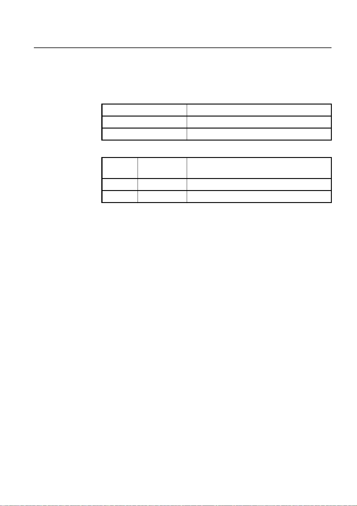
Reason for Update
Summary:
Second Edition for Release BR7.0
Details:
Chapter/Section Reason for Update
All New Release BR7.0
Revised Chapter
Issue History
Issue
Number
1 07/2003 First Edition for new Release BR7.0
2 12/2003 Second Edition for Release BR7.0
Date of issue Reason for Update
A30808-X3247-L14-2-7618
3
Page 4

Technical Description (TED:BSS)
BS-240/241
Information
Base Station System
4
A30808-X3247-L14-2-7618
Page 5

Information
Base Station System
Technical Description (TED:BSS)
BS-240/241
This document consists of a total of 70 pages. All pages are issue 2.
Contents
1 Introduction. . . . . . . . . . . . . . . . . . . . . . . . . . . . . . . . . . . . . . . . . . . . . . . . . . 9
1.1 Main Features. . . . . . . . . . . . . . . . . . . . . . . . . . . . . . . . . . . . . . . . . . . . . . . 10
1.2 Technical Data . . . . . . . . . . . . . . . . . . . . . . . . . . . . . . . . . . . . . . . . . . . . . . 12
2 Hardware Architecture . . . . . . . . . . . . . . . . . . . . . . . . . . . . . . . . . . . . . . . . 14
2.1 Board Redundancy. . . . . . . . . . . . . . . . . . . . . . . . . . . . . . . . . . . . . . . . . . . 17
2.1.1 AC/DC. . . . . . . . . . . . . . . . . . . . . . . . . . . . . . . . . . . . . . . . . . . . . . . . . . . . . 17
2.1.2 Core . . . . . . . . . . . . . . . . . . . . . . . . . . . . . . . . . . . . . . . . . . . . . . . . . . . . . . 17
2.2 Power Amplifier Output Level (typical values) . . . . . . . . . . . . . . . . . . . . . . 18
2.3 Rack Configuration . . . . . . . . . . . . . . . . . . . . . . . . . . . . . . . . . . . . . . . . . . . 19
3 Description of Modules . . . . . . . . . . . . . . . . . . . . . . . . . . . . . . . . . . . . . . . . 24
3.1 Core (COBA and COSA) . . . . . . . . . . . . . . . . . . . . . . . . . . . . . . . . . . . . . . 25
3.1.1 Core Basis (COBA2P8) . . . . . . . . . . . . . . . . . . . . . . . . . . . . . . . . . . . . . . . 27
3.1.2 Core Satellite (COSA6P16) . . . . . . . . . . . . . . . . . . . . . . . . . . . . . . . . . . . . 29
3.2 Carrier Unit (CU). . . . . . . . . . . . . . . . . . . . . . . . . . . . . . . . . . . . . . . . . . . . . 30
3.3 EDGE Carrier Unit . . . . . . . . . . . . . . . . . . . . . . . . . . . . . . . . . . . . . . . . . . . 32
3.4 GMSK Carrier Units (GCU). . . . . . . . . . . . . . . . . . . . . . . . . . . . . . . . . . . . . 37
3.5 Duplexer Amplifier Multi Coupler (DUAMCO). . . . . . . . . . . . . . . . . . . . . . . 37
3.6 DI(=2) Amplifier Multi Coupler (DIAMCO). . . . . . . . . . . . . . . . . . . . . . . . . . 38
3.7 Filter Combiner (FICOM) . . . . . . . . . . . . . . . . . . . . . . . . . . . . . . . . . . . . . . 38
3.8 Tower Mounted Amplifier (TMA). . . . . . . . . . . . . . . . . . . . . . . . . . . . . . . . . 38
3.9 High Power Duplexer Unit (HPDU). . . . . . . . . . . . . . . . . . . . . . . . . . . . . . . 39
3.10 DC Panel (DCP) . . . . . . . . . . . . . . . . . . . . . . . . . . . . . . . . . . . . . . . . . . . . . 39
3.11 Alarm Collection Terminal (ACT) . . . . . . . . . . . . . . . . . . . . . . . . . . . . . . . . 39
3.12 AC/DC Converter (AC/DC) . . . . . . . . . . . . . . . . . . . . . . . . . . . . . . . . . . . . . 40
3.12.1 DC and Battery Controller (DCBCTRL) . . . . . . . . . . . . . . . . . . . . . . . . . . . 41
3.13 Overvoltage Protection and Tracer (OVPT) . . . . . . . . . . . . . . . . . . . . . . . . 41
3.14 Abis Connection Module (ABISCON) . . . . . . . . . . . . . . . . . . . . . . . . . . . . . 41
3.15 Abis Link Equipment (LE) . . . . . . . . . . . . . . . . . . . . . . . . . . . . . . . . . . . . . 42
3.16 Cover Parts. . . . . . . . . . . . . . . . . . . . . . . . . . . . . . . . . . . . . . . . . . . . . . . . . 42
3.17 Backup Battery (BATTERY) . . . . . . . . . . . . . . . . . . . . . . . . . . . . . . . . . . . . 42
3.18 Fan . . . . . . . . . . . . . . . . . . . . . . . . . . . . . . . . . . . . . . . . . . . . . . . . . . . . . . . 43
3.19 Heat Exchanger (HEX) . . . . . . . . . . . . . . . . . . . . . . . . . . . . . . . . . . . . . . . 44
A30808-X3247-L14-2-7618
4 Antenna Combiners and Receiving Paths . . . . . . . . . . . . . . . . . . . . . . . . . 45
4.1 Methods of Combining . . . . . . . . . . . . . . . . . . . . . . . . . . . . . . . . . . . . . . . . 45
4.1.1 Typical Combiner Losses (TX path) and Output Power Level . . . . . . . . . . 52
4.1.2 DUAMCO - DIAMCO GAIN (RX Path) . . . . . . . . . . . . . . . . . . . . . . . . . . . . 54
4.1.3 Parameters of Tower Mounted Amplifier (TMA) . . . . . . . . . . . . . . . . . . . . 55
4.1.4 Examples of possible BTSE configurations . . . . . . . . . . . . . . . . . . . . . . . . 57
4.2 Receiving Paths . . . . . . . . . . . . . . . . . . . . . . . . . . . . . . . . . . . . . . . . . . . . . 61
4.2.1 Antenna diversity techniques . . . . . . . . . . . . . . . . . . . . . . . . . . . . . . . . . . . 61
4.2.1.1 Antenna System Modules. . . . . . . . . . . . . . . . . . . . . . . . . . . . . . . . . . . . . . 61
4.2.2 Receiver Sensitivity. . . . . . . . . . . . . . . . . . . . . . . . . . . . . . . . . . . . . . . . . . . 62
4.3 Transmission Diversity Time Delay. . . . . . . . . . . . . . . . . . . . . . . . . . . . . . . 62
5
Page 6

TechnicalDescription(TED:BSS)
BS-240/241
4.3.1 Functionality. . . . . . . . . . . . . . . . . . . . . . . . . . . . . . . . . . . . . . . . . . . . . . . . . 63
4.4 FCC Issues (for US Market only). . . . . . . . . . . . . . . . . . . . . . . . . . . . . . . . .65
5 Power Supply and Battery Backup. . . . . . . . . . . . . . . . . . . . . . . . . . . . . . . . 67
5.1 Support of Emergency Operation for 3rd Party BBU System . . . . . . . . . . . 67
6 Abbreviations . . . . . . . . . . . . . . . . . . . . . . . . . . . . . . . . . . . . . . . . . . . . . . . . 69
Information
Base Station System
6
A30808-X3247-L14-2-7618
Page 7

Information
Base Station System
Technical Description (TED:BSS)
BS-240/241
Illustrations
Fig. 2.1 BS-240 Indoor Cabinet and BS-241 Outdoor Cabinet (Base Racks) . . 14
Fig. 2.2 Functional Blocks of the BS-240/241. . . . . . . . . . . . . . . . . . . . . . . . . . . 15
Fig. 2.3 Redundant COREs and their Interfaces . . . . . . . . . . . . . . . . . . . . . . . . 17
Fig. 2.4 BS-240 Base Rack and 2 Extension Racks. . . . . . . . . . . . . . . . . . . . . . 20
Fig. 2.5 BS-241 Base Rack and 2 Extension Racks. . . . . . . . . . . . . . . . . . . . . . 21
Fig. 2.6 Possible Configuration of Service1 Rack and Service2 Rack . . . . . . . . 22
Fig. 2.7 BS-240/241 fully Equipped with 24 Carriers . . . . . . . . . . . . . . . . . . . . . 23
Fig. 3.1 Backplane Slot Configuration of Core . . . . . . . . . . . . . . . . . . . . . . . . . . 26
Fig. 3.2 COBA2P8 Block Diagram . . . . . . . . . . . . . . . . . . . . . . . . . . . . . . . . . . . 27
Fig. 3.3 Structure of ACLK Function . . . . . . . . . . . . . . . . . . . . . . . . . . . . . . . . . . 28
Fig. 3.4 COSA6P16 Block Diagram . . . . . . . . . . . . . . . . . . . . . . . . . . . . . . . . . . 29
Fig. 3.5 Carrier Unit Block Diagram . . . . . . . . . . . . . . . . . . . . . . . . . . . . . . . . . . 30
Fig. 3.6 PATRX Block Diagram. . . . . . . . . . . . . . . . . . . . . . . . . . . . . . . . . . . . . . 31
Fig. 3.7 Principal Data Flow on SIPRO. . . . . . . . . . . . . . . . . . . . . . . . . . . . . . . . 32
Fig. 3.8 EPATRX and ESIPRO Function Block Diagram . . . . . . . . . . . . . . . . . . 34
Fig. 3.9 Data Flow in ESIPRO . . . . . . . . . . . . . . . . . . . . . . . . . . . . . . . . . . . . . . 36
Fig. 3.10 Alarm Collection Terminal (ACTM and ACTP). . . . . . . . . . . . . . . . . . . . 40
Fig. 3.11 Example of Battery Backup Systems Connected to the AC/DC . . . . . . 43
Fig. 4.1 Overview of Combining Options . . . . . . . . . . . . . . . . . . . . . . . . . . . . . . 45
Fig. 4.2 DUAMCO 2:2. . . . . . . . . . . . . . . . . . . . . . . . . . . . . . . . . . . . . . . . . . . . . 47
Fig. 4.3 DUAMCO 4:2. . . . . . . . . . . . . . . . . . . . . . . . . . . . . . . . . . . . . . . . . . . . . 47
Fig. 4.4 DUAMCO 8:2. . . . . . . . . . . . . . . . . . . . . . . . . . . . . . . . . . . . . . . . . . . . . 48
Fig. 4.5 FICOM 8:1 . . . . . . . . . . . . . . . . . . . . . . . . . . . . . . . . . . . . . . . . . . . . . . . 49
Fig. 4.6 DIAMCO. . . . . . . . . . . . . . . . . . . . . . . . . . . . . . . . . . . . . . . . . . . . . . . . . 50
Fig. 4.7 HPDU. . . . . . . . . . . . . . . . . . . . . . . . . . . . . . . . . . . . . . . . . . . . . . . . . . . 51
Fig. 4.8 Configuration with HPDU, DUBIAS and TMA . . . . . . . . . . . . . . . . . . . . 52
Fig. 4.9 Multi-cell (3,3,2): with 3 DUAMCO 4:2. . . . . . . . . . . . . . . . . . . . . . . . . . 57
Fig. 4.10 Multi-cell (3,3,2): with 2 DUAMCO 4:2 and 1 DUAMCO 2:2 . . . . . . . . . 58
Fig. 4.11 Single-cell (8,0,0): with FICOM and DIAMCO . . . . . . . . . . . . . . . . . . . . 58
Fig. 4.12 Single-cell (8,0,0): with 2 DUAMCO 4:2. . . . . . . . . . . . . . . . . . . . . . . . . 59
Fig. 4.13 Multi-cell (2,2,2): with 3 DUAMCO 2:2. . . . . . . . . . . . . . . . . . . . . . . . . . 59
Fig. 4.14 Single-cell (11...16,0,0): FICOMs, DIAMCOs and HPDUs in 2 Racks. . 60
Fig. 4.15 Capacity Downlink Improvements for TX Diversity . . . . . . . . . . . . . . . . 63
Fig. 4.16 BTS Rack Cabling for Transmitter Diversity Operation . . . . . . . . . . . . . 64
A30808-X3247-L14-2-7618
7
Page 8

Technical Description (TED:BSS)
BS-240/241
Tables
Tab. 1.1 Technical Data . . . . . . . . . . . . . . . . . . . . . . . . . . . . . . . . . . . . . . . . . . . . 12
Tab. 1.2 Frequency Bands . . . . . . . . . . . . . . . . . . . . . . . . . . . . . . . . . . . . . . . . . .13
Tab. 2.1 Power Amplifier Output Level . . . . . . . . . . . . . . . . . . . . . . . . . . . . . . . . . 18
Tab. 3.1 Units and Modules . . . . . . . . . . . . . . . . . . . . . . . . . . . . . . . . . . . . . . . . . 24
Tab. 3.2 GMSK/8PSK Linear Modulation . . . . . . . . . . . . . . . . . . . . . . . . . . . . . . . 33
Tab. 4.1 Insertion loss of DUAMCOs, FICOMs, HPDU and TMA. . . . . . . . . . . . . 52
Tab. 4.2 Parameters of DUAMCO - DIAMCO. . . . . . . . . . . . . . . . . . . . . . . . . . . . 54
Tab. 4.3 Parameters of 900 MHz Tower Mounted Amplifier. . . . . . . . . . . . . . . . . 55
Tab. 4.4 Parameters of 1800 MHz Tower Mounted Amplifier. . . . . . . . . . . . . . . . 56
Tab. 4.5 Parameters of 900/1800 MHz Tower Mounted Amplifier . . . . . . . . . . . . 57
Tab. 4.6 Maximum RF Power Output Values . . . . . . . . . . . . . . . . . . . . . . . . . . . . 65
Tab. 4.7 Maximum RF Power Output Values . . . . . . . . . . . . . . . . . . . . . . . . . . . . 66
Information
Base Station System
8
A30808-X3247-L14-2-7618
Page 9

Information
Base Station System
Technical Description (TED:BSS)
BS-240/241
1 Introduction
The architecture of BS-240/241 provides maximum flexibility to develop higher capacity
BTSs with reduced volume and an expanded number of 24 TRXs in 3 Racks with a
modularity of 8 TRXs per Rack. Any operation for rack extension or TRX substitution
doesn’t involve service interruption.The provision of a full spectrum of combining equipment allows high power and minimized numberof antennas. High receiversensitivity is
also guaranted.
The modular architecture and the flexible internal structure, enables the BS-240/241 to
provide new GSM features such as EDGE; this platform ensures that network evolution
is as smooth as possible.
The use of the latest technology reduces power consumption and improves reliability;
the reliability is also increased by the redundancy of all core modules. Easy integration
is possible in the already installed sites, for the backward compatibility with existing
SIEMENS SBS systems. High Site efficiency is assured for composite transmit power
with minimal footprint requirements.
Homogenous service throughout the network is assured by common BTS SW running
on all the platforms.
The BS-240/241 primarily consists of:
• Carrier oriented boards called carrier unit (CU),
• Core boards (COSA, COBA) and
• Combining equipment
A30808-X3247-L14-2-7618
9
Page 10

Technical Description (TED:BSS)
BS-240/241
1.1 Main Features
The BS-240/241 is designed for max. 24 carriers in 3 Racks/Shelters plus Service
Racks/Shelters, if needed. The minimum configuration is one Rack or one Shelter with
a Service Rack/Shelter. Service Racks/Shelters can be configured to accommodate
Backup Batteries and Link Equipment. A Service Rack/Shelter can be equipped with
AC/DC Converters. Easy Rack/Shelter Extension is possible with one or two Extension
Racks/Shelters.
The BS-240/241 can be configured for the systems GSM 850, GSM 900, GSM 1800 and
GSM 1900 with the following configurations:
– Single band
– Dualband: GSM 900, GSM 1800; GSM 900, GSM 1900; GSM 850, GSM 1800 and
GSM 850, GSM 1900 :
– GSM 900, GSM 1800 cell mixed frequencies
– Common BCCH channel for GSM 900, GSM 1800 cell (dual band)
– Single cell
– Multi cell
Up to 6 cells per Rack and up to 12 cells can be supported. A special case is the feature
“concentric cell”; one cell with 2 supply areas (inner and complete area). This feature
can be used in omnicells as well as in multicells with sectors.
The following combining options are supported:
– Antenna combining with CU pairs to apply transmission diversity time delay.
– Antennacombining withduplexers(DUAMCO) can be appliedfor 2, 4 and8carriers.
RF amplifier and multicoupler for the RX path are integrated
– Antenna combining with Filter Combiners (FICOM) is possible for up to 8 carriers
onto one TX antenna
– Cascading of multicoupler equipment (DIAMCO) is possible for up to 24 carriers
– High Power Duplexer (HPDU) for reduction of the necessary numbers of antennas
in case of FICOM per cell for up to 8 carriers can be applied
– Every BTSE has core equipment in the Base Rack/Shelter
– Sensitivityis better than GSM requirements at the Rack entry by using DUAMCO or
DIAMCO units
– BTSplus sensitivity is better than GSM requirements at the antenna connector by
using Tower Mounted Amplifiers (TMA)
– EDGE Carrier Units (ECU)
– Mixed Configurations of Cells/Sectors applying both EDGE Carrier Units (ECU) and
“normal” Carrier Units (CU)
Traffic Channels:
– Full-Rate (FR)
– Half-Rate (HR)
– Enhanced Full-Rate (EFR)
– Adaptive Multi Rate Codec (AMR)
Services:
– GPRS
– HSCSD
– EDGE
Frequency Hopping:
– Baseband
– Synthesizer
Information
Base Station System
10
A30808-X3247-L14-2-7618
Page 11

Information
Base Station System
Technical Description (TED:BSS)
BS-240/241
Redundancy:
– SW Support of Core Redundancy
– SW Support of BCCH Redundancy
– AC/DC n+1 redundancy. (n+1) AC/DCConverterswork in load sharing, butn AC/DC
are able to supply the whole BS-240/241 including Service Racks/Shelters
Abis interface:
– Enhanced Full-Rate TCH
– Full-Rate and Half-Rate TCH
– AMR TCH
– Submultiplexing4x16kbit/s onto one 64 kbit/s timeslot for handling Full-Rate TCH
on Um interface
– Handling of 4x(2x8) kbit/s onto one64 kbit/s timeslot for half-rate TCH on Uminter-
face
– Drop and insert feature on 2 Mbit/s (E1) and 1.5 Mbit/s (T1) links is available on a
16 kbit/s and a 64 kbit/s basis
– Star, loop and multidrop chain connections
– Cross connect function
– Change of PCM line configuration from star to multidrop or loop and vice versa is
possible without any interruption of service
– Multiple Abis LAPD links; load sharing and LAPD fault recovery
– External clock synchronisation
– Over-Voltage Protection with OVPT
Abis link media:
– Wire
– Fiber optic
– Micro-Wave
Fault procedures:
– Automatic Recovery procedure of faulty objects in BTS
– Online RF Loopback
A30808-X3247-L14-2-7618
11
Page 12

Technical Description (TED:BSS)
BS-240/241
1.2 Technical Data
The BS-240/241 family with 24 transceivers can be supplied in the following versions:
– A BS-240 for indoor installation.
– A BS-241 for outdoor installation (also equipped with: integrated power supply,
battery, microwave equipment, integrated link equipment, heat exchangerand cross
connector).
BS-240/241 consist in a split BTS architecture, with:
- 1 Base Rack
- Up to 2 Extension Racks
- Up to 2 Service Racks (Service1 or Service2).
Characteristics BS-240 (indoor) BS-241 (outdoor)
Max. TRX per BTSE 24 24
(in more than one Rack)
Max. TRX per cell 24 24
(in more than one Rack)
Information
Base Station System
Dimensions (mm) (HxWxD) 1600x600x450 (5’3”x2’x1’6”) 1750x700x650 (5’9”x2’4”x2’2”)
(Base Racks) (incl. Plinth)
Volume net 432 l 705 l
796 l (incl. Plinth)
Maximum power consumption 1600 W 1750 W
Weight of Basic Rack empty ca.60 kg (132 Lbs) ca.60 kg (132 Lbs)
Weight of Shelter empty ca.110 kg (242 Lbs)
Weight of Service1 Rack equipped with: - 1 Frame AC/DC incl. 6 AC/DC Modules (ca. 27 kg/60 Lbs)
- 1 Frame for Battery incl. 1Battery (48V / 85 Ah) (ca. 140 kg/309
Lbs)
-1 Mounting Kitfor Link Equipmentincl. 1 Frame NTPM, Frame for
Fan Unit and two FAN's (ca. 16 kg/ 35 Lbs)
- 1 Rack (ca. 60 kg/132 Lbs)
Sum: ca. 243 kg (536 Lbs)
Weight of Service1 Rack equipped with: - 2 Frames AC/DC and
- 2 Frames for Battery
Not possible: max. 3 Frames pro Rack / Shelter can be equipped.
Weight of Service1 Rack equipped with: - 1 Frame AC/DC incl. 6 AC/DC Modules (ca. 27 kg/60 Lbs)
-1 Mounting Kitfor Link Equipmentincl. 2 Frame NTPM, Frame for
Fan Unit and two FAN's (ca. 21 kg/46 Lbs)
- 1 Rack (ca. 60kg/132 Lbs)
Sum: ca. 108 kg (238 Lbs)
Weight of Frame: Frame with Battery ca. 140 kg (309 Lbs)
FrameAC/DC with 6 AC/DC Modules ca. 27 kg (60 Lbs)
Frame with 4 CU's and 2 MUCO's ca. 40 kg (88 Lbs)
Frame with 4 ACOM's ca. 40 kg (88 Lbs))
1 HEX ca. 5.6 kg (12 Lbs)
Tab. 1.1 Technical Data
12
A30808-X3247-L14-2-7618
Page 13

Information
Base Station System
Characteristics BS-240 (indoor) BS-241 (outdoor)
Technical Description (TED:BSS)
BS-240/241
Temperature range (˚C) -5 °C to +55 °C
+23 °F to +131 °F
Tab. 1.1 Technical Data
Frequency-Band Uplink (MHz) Downlink (MHz)
GSM 850 824.2 - 848.8 869.2 - 893.8
P-GSM 900 (Primary) 890.2 - 914.8 935.2 - 959.8
E-GSM 900 (Extension) 880.2 - 914.8 925.2 - 959.8
R-GSM 900 (Railway) 876.2 - 914.8 921.2 - 959.8
GSM-RE 900 (Railway Extension) 876.2 - 901.0 921.2 - 946.0
GSM 1800 1710.2 -1784.8 1805.2 -1879.8
GSM 1900 1850.2 -1909.8 1930.2 -1989.8
Tab. 1.2 Frequency Bands
-45 °C to +50 °C
-49 °F to +122 °F
A30808-X3247-L14-2-7618
13
Page 14
Technical Description (TED:BSS)
BS-240/241
2 Hardware Architecture
The BS-240/241 is designed to achieve commonality of boards to serve both GSM 850,
GSM 900 with its different deviates (GSM 1800, GSM 1900) and standards selected for
mobile communication systems. Moreover, the architecture of BS-240/241 provides
maximum flexibility to develop large and small BTSs which havesimilar costs per TRX.
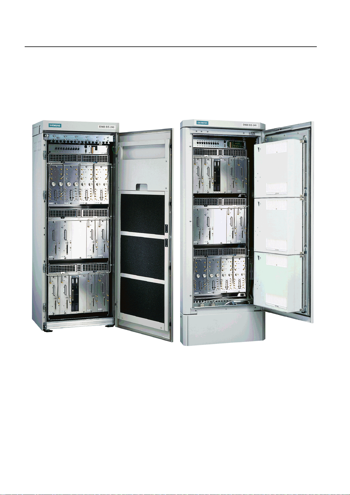
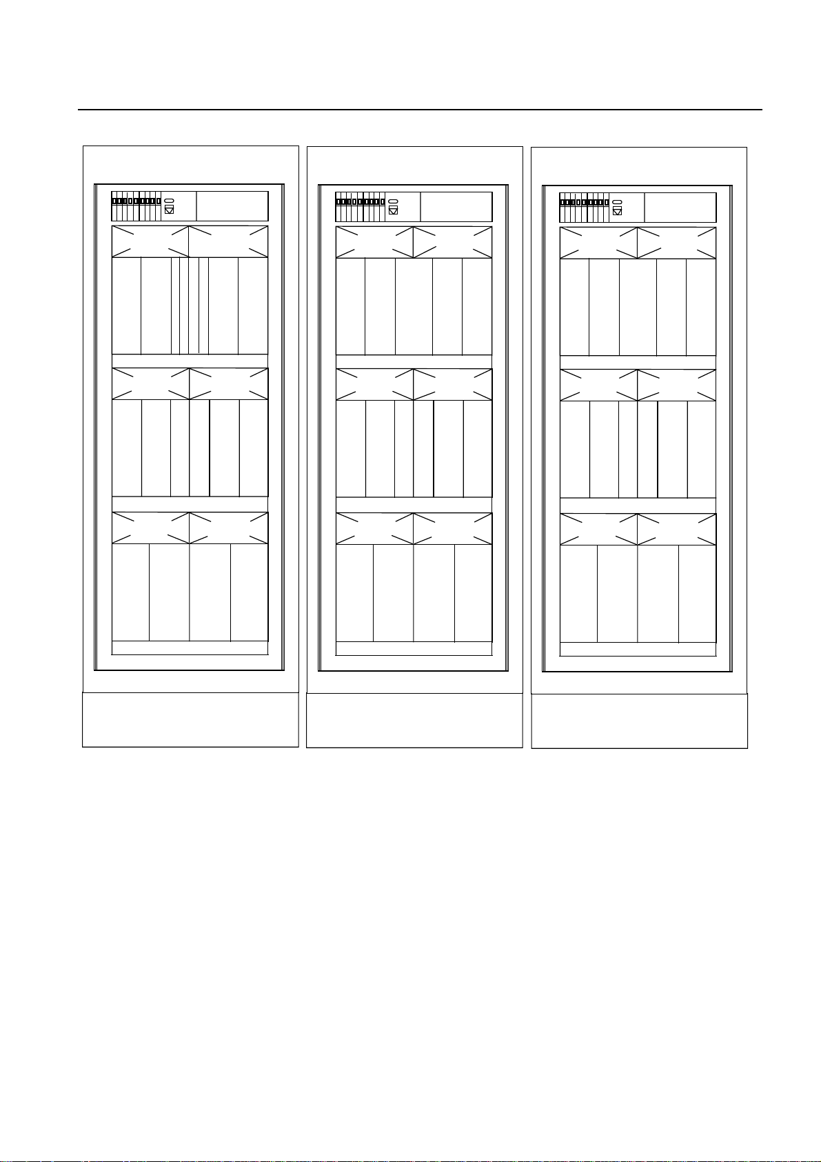
Fig. 2.1 shows the Base Rack Cabinets.
Information
Base Station System
Fig. 2.1 BS-240 Indoor Cabinet and BS-241 Outdoor Cabinet (Base Racks)
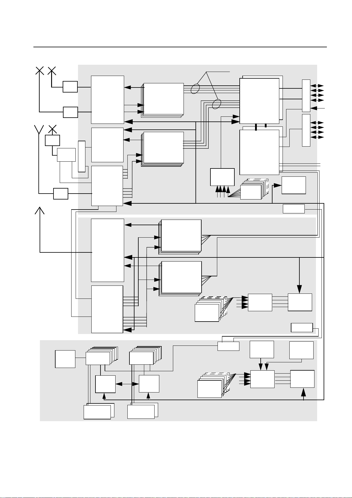
The BTS functional blocks of the BS-240/241 are shown in Fig. 2.2
14
A30808-X3247-L14-2-7618
Page 15
Information
Base Station System
Technical Description (TED:BSS)
BS-240/241
Cell 0
Cell 1
Cell 1
TMA
TMA
TMA
DUBIAS
TMA
Base Rack
DUAMCO
H
P
D
U
RXCA0
FICOM
DIAMCO
FICOM
4xTX
RX
RXDIV
4xTX
RX
RXCA1
RXDIV
4xTX
RXDIV
RX
CU 0
CU 7
CU 0
CC-Links
ACTC
2 PCM
COBA
COSA
FAN
Ext. Sync.
2 PCM
4 PCM
to next ext. rack
*
ACTM
DCP
Extension Rack
O
V
P
O
V
P
T
T
Abis
Sync.
Abis
4xTX
Cascading
DIAMCO
RX
RXDIV
RX
RXDIV
CU 7
Service Rack
ACP
AC/DC
DCBCTRL
BATTERY
AC/DC
DCBCTRL
BATTERY
* not present in case of BTSE with reduced number of fan
FAN
FAN
CAN BUS
*
DCP
*
ACTC
LE 0
ACTC
ACTP
DCP
LE 1
ACTP
Fig. 2.2 Functional Blocks of the BS-240/241
A30808-X3247-L14-2-7618
15
Page 16

Technical Description (TED:BSS)
BS-240/241
AC/DC AC/DC converter DCBCTRL DC and Battery Controller
ACP AC Panel DCP DC Panel
ACTC Alarm Collection Terminal Connection module DIAMCO DI(2) Amplifier Multi Coupler
ACTM Optional Alarm Collection Terminal for Master Rack DUAMCO Duplex Amplifier Multicoupler
ACTP Alarm Collection Terminal for Slave Rack FICOM Filter Combiner
CAN Controller Area Network HPDU High Power Duplexer
COBA Core Basis (COBA2P8) LE Link Equipment
COSA Core Satellite (COSA6P16) TMA Tower Mounted Amplifier
CU Carrier Unit
The architecture of BS-240/241 provides maximum flexibility to develop large and small
BTSs.
The BS-240/241 mainly consists of:
– carrier oriented boards called carrier unit (CU),
– core boards (COSA, COBA) and
– combining equipment
Up to 8PCM linescan beconnected to the core boards. In order to provide cost effective
solutions, the core boards are scalable (COBA, COSA). In addition, also the BTS itself
is scalable. It is possible to connect up to 2 Extension Racks to a Base Rack.
The main communication between the modules is provided by means of bi-directional
serial link communications between the carrier units (CU) and the core boards. The
serial link also provides an effective means to realize baseband frequency hopping.
Despite the fact that synchronization information is also transported via the serial links,
no differential length constraints apply for the lines of the serial link.
All alarms, beside the alarms that are generated in the core and in the CU boards, are
transported via theCAN bus. Alarms of the CU boards are transmitted via CC-Link.Core
boards use their interface bus.
The carrier unit(s) provide all analog and digital signal processing including a RF power
stage necessary to process a single carrier (e.g., GSM 8 TCHs). The carrier unit(s) interface with the combining equipment on the one side and with the core modules on the
other. The core boards provide functions common to all carriers within the BS-240/241
(e.g., clock generation, O&M processing,...) as well as LAPD processing for the different
carriers.
Base Station System
Information
16
A30808-X3247-L14-2-7618
Page 17

Information
Base Station System
2.1 Board Redundancy
2.1.1 AC/DC
2.1.2 Core
Technical Description (TED:BSS)
BS-240/241
Redundancy in the SBS ensures survival of the system even in the event of multiple failures. Modular architecture, in conjunction with the concept of split functions, guarantees
maximum survivability with a minimum of additional hardware.
Up to 6 AC/DC converters can be equipped in the service1 Rack which provide N+1
redundancy. AC/DC converters work in load sharing, but n AC/DC are able to supply the
whole BS-240/241.
The Core can consist of up to 2 (without redundancy) or up to 4 (with redundancy)
boards, which have a common backplane. The block diagram depicts the 2n CORE
redundancy and the embedding of the active and the passive CORE into the BTS, and
the interrelation of both COREs.
CU
SELIC
SELIC
BISON
FALC
ABIS
CAN
LMT
Fig. 2.3 Redundant COREs and their Interfaces
Both COREs (COBA0/COSA0 and COBA1/COSA1) have link interfaces to the ABIS
lines, but only one (the active CORE) can be connected.
On the backplane of the BTS, one connector provides a link of the LMT to the current
active CORE. In the case of a CORE switch over, the switch logic switches that
connector to the new active CORE. The same holds for the CAN bus (alarm bus), i.e.,
both COREs have the same CAN bus address where at any time at most one CORE is
an active CAN bus node.
Both the active and the passive CORE have links to the carrier units (CU); in reverse,
each CU is linked with both COREs. The traffic data are transmitted transparently
through the active CORE. Signal processing takes place only within the CUs.
The endpoints of each link are built up by SELIC ASICs (note: one SELIC contains
double functionality), where on the CU, one SELICserves two COREs. In thecase of a
SELIC SELIC SELIC
RD
Interf.
µP
Switch
Logic
Route Clock
CLK
CORE 0
CU
SELIC
Redundancy Link
Switch Logic Link
Route Clock
(Frame Sync)
RD
Interf.
Switch
Logic
CLK
SELICSELIC
µP
Route Clock
CORE 1
CU
SELIC
BISON
FALC
A30808-X3247-L14-2-7618
17
Page 18

Technical Description (TED:BSS)
BS-240/241
switch over, the SELICs on the active CORE are disabled by the switch logic and the
SELICs on the passive one are enabled. The SELICs on the CORE have to know
whether they are on the active or on the passive CORE. For this reason the SELICs
need a active/passive pin, which is served by the redundancy switch logic. When a
switch over occurs, the switch logic sets the active/passive pin of the former active
SELICs to "passive" and that of the former passive SELICs to "active".
The SELICs on the CUs have to recognize automatically which link comes from the
active CORE and which link from the passive one, i.e. it has to recognise a CORE switch
over by itself.
The RD interface (redundancy interface) is realized as a 2 Mbit/s HDLC link which
provides a communication interface between the two main processors (mP).
The switch logic is a flip-flop distributed over the two COREs. It manages the HW part
of a switch over and enables the COREs to know about their states as active/passive.
The CLK of the active CORE is connected with the one on the passive CORE. It allows
the passive CLK to be synchronized to the active one.
NOTE: the redundancy is implemented in a cold-standby mode, i.e., all calls will get lost
if a CORE switch over occurs.
Information
Base Station System
2.2 Power Amplifier Output Level (typical values)
Modulation Output Power
(dBm)
GSM 900 CUGV3 GMSK 47.3 53.7
GSM 900 CUGV4 GMSK 47.3 53.7
GSM 1800 CUDV3 / CUDV4 GMSK 45.7 37.1
GSM 1900 CUPV4 GMSK 45.7 37.1
GSM 900 GCUGV2 GMSK 47.3 53.7
GSM 1800 GCUDV2 GMSK 47.3 53.7
GSM 850 ECU 850 HPV2 GMSK 48.3 67.6
“ “ “ “ 8PSK 46.3 42.7
GSM 850 ECU 850 V3 GMSK 48.3 67.6
“ “ “ “ 8PSK 46.3 42.7
GSM 900 ECU GV3 GMSK 48.3 67.6
Output Power
(Watt)
“ “ “ “ 8PSK 46.3 42.7
GSM 1800 ECU DV2 GMSK 47.3 53.7
“ “ “ “ 8PSK 45.3 33.9
GSM 1800 ECU DHPV3 GMSK 48.3 67.6
Tab. 2.1 Power Amplifier Output Level
18
A30808-X3247-L14-2-7618
Page 19

Information
Base Station System
Technical Description (TED:BSS)
BS-240/241
“ “ “ “ 8PSK 45.3 33.9
GSM 1900 ECU PV2 GMSK 47.3 53.7
“ “ “ “ 8PSK 45.3 33.9
GSM 1900 ECU PHPV2 GMSK 48.3 67.6
“ “ “ “ 8PSK 45.3 33.9
GSM 1900 ECU PHPV3 GMSK 48.3 67.6
“ “ “ “ 8PSK 45.3 33.9
Tab. 2.1 Power Amplifier Output Level
Carrier Unit (CU )
GSM 900: minimum guaranteed output power CU = 50 Watt tolerance value: 47.0 dBm
i
- 47.6 dBm (50 W - 57.5 W); GSM1800, GSM1900: minimumguaranteed outputpower
CU = 34 Watt tolerance value: 45.3 dBm - 46.0 dBm (34 W - 39.5 W).
The mentioned data are guaranteed from Module Factory Test only. The typical output
power at CU output is for:
GSM 900: 47,3 dBm GSM 1800: 45.7 dBm
To verify the typical output power values in fieldmeasurements, the tolerance value of
the used measurement equipment, environmental conditions and GSM 05.05 specifications have to be considered.
Modulation Output Power
(dBm)
Output Power
(Watt)
Carrier Unit (GCU )
GSM 900: minimum guaranteed output power GCU = 50 Watt (GSMK); GSM 1800:
i
minimum guaranteed output power GCU = 50 Watt (GSMK).
The GSM 1800 variant of the GCU V2 offers higher output power than the corresponding CU (about 15 Watt): the increased output power of the GSM 1800 GCU V2,
has to be taken into consideration in the radio network planning.
EDGE Carrier Unit (ECU )
GSM 850, GSM 900: minimum guaranteed output power ECU = 63 Watt (GMSK) / 40
i
Watt (8PSK); GSM 1800, GSM 1900: minimum guaranteed output power ECU = 50
Watt (GMSK) / 32 Watt (8PSK).
The mentioned data are guaranteed from Module Factory Test only.
2.3 Rack Configuration
The BS-240/241 family, with 8 transceivers per Rack, which is expandable up to 24
transceivers in 3 Racks and can be supplied in two versions:
– a BS-240 for indoor installation, and
– a BS-241 for outdoor installation (also equipped with integrated link equipment,
Battery Backup and a cooling system).
A30808-X3247-L14-2-7618
19
Page 20
Technical Description (TED:BSS)
BS-240/241
There are 4 different types of Rack:
– Base Rack/Shelter (with Core modules)
– Extension Rack/Shelter (for more then 8 CU’s)
– Service1 Rack/Shelter (with AC/DC modules)
– Service2 Rack/Shelter (for LE and batteries)
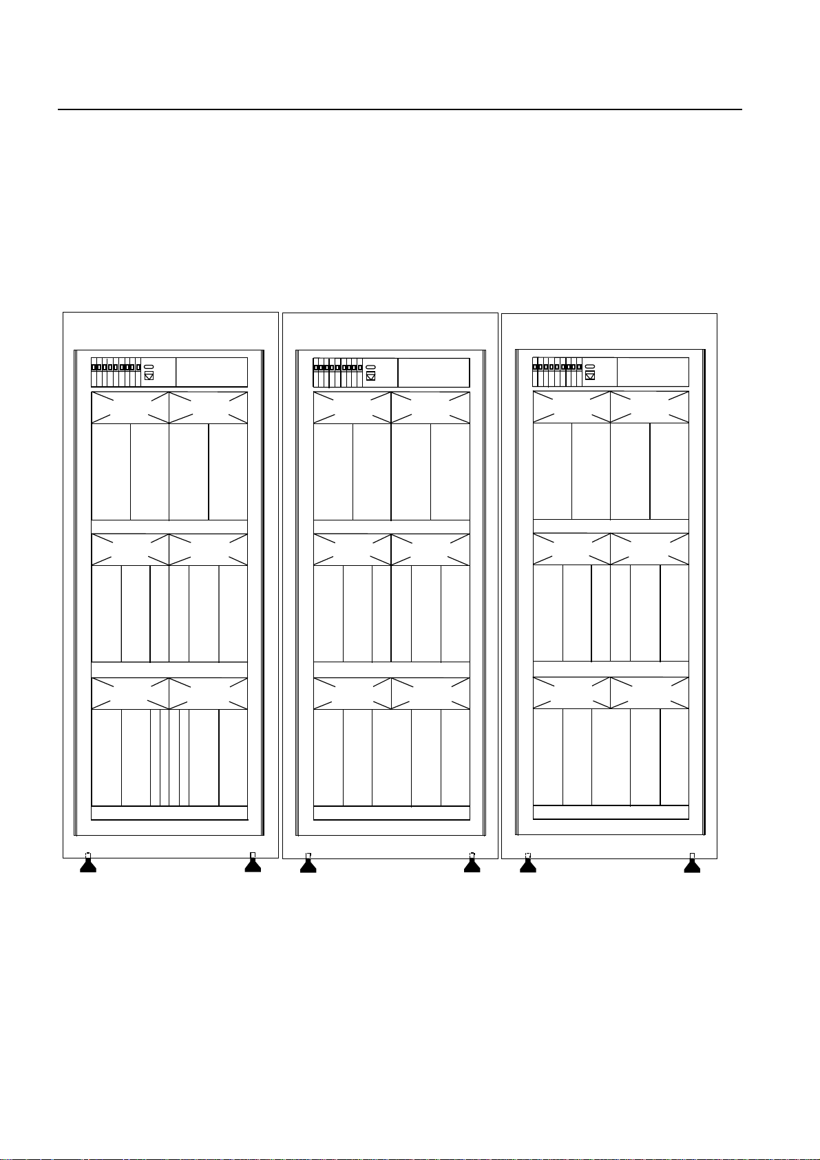
It is possible to connect up to 3 Racks/Shelters together (1 Base Rack, 2 Extension
Racks; the more possible Racks/Shelters called Service Rack/Shelter are not part of a
Rack Extension in the proprietary sense) that realizes then the performance of a 24 TRX
BTSE as shown in Fig. 2.4 and Fig. 2.5:
Information
Base Station System
SIEMENS
ACOM
0
CU
2
CU
0
FAN 0
ACOM
FAN 2
CU
3
FAN 4 *
CU
1
1
ACOM
MUCO 1
MUCO 0
1
0
0
DC-PANEL
ACT-C
FAN 1
ACOM
2
FAN 3
CU
6
FAN 5*
CU
4
1
3
CU
7
CU
BS-240
5
SIEMENS
ACOM
0
CU
2
CU
0
FAN 0
FAN 2
CU
3
FAN 4*
CU
1
ACOM
1
ACOM
0
MUCO
DC-PANEL
ACT-C
FAN 1
ACOM
2
FAN 3
CU
1
6
MUCO
FAN 5*
CU
4
3
BS-240
CU
7
CU
5
SIEMENS
ACOM
0
CU
2
CU
0
FAN 0
FAN 2
CU
3
FAN 4*
CU
1
ACOM
1
ACOM
0
MUCO
DC-PANEL
ACT-C
FAN 1
ACOM
2
FAN 3
CU
1
6
MUCO
FAN 5*
CU
4
BS-240
3
CU
7
CU
5
COSA
COBA
COSA
COBA
* not present in case of BTSE with reduced number of fans
Fig. 2.4 BS-240 Base Rack and 2 Extension Racks
20
A30808-X3247-L14-2-7618
Page 21
Information
Base Station System
Technical Description (TED:BSS)
BS-240/241
SIEMENS
CU
0
CU
2
ACOM
0
FAN 0
CU
1
FAN 2
CU
3
FAN 4*
ACOM
1
1
0
0
COBA
COSA
COBA
MUCO 0
ACOM
DC-PANEL
ACT-C
FAN 1
CU
4
1
COSA
FAN 3
CU
6
MUCO 1
FAN 5*
ACOM
2
CU
5
CU
7
3
BS-241
SIEMENS
CU
0
CU
2
ACOM
0
FAN 0
CU
1
FAN 2
CU
3
FAN 4*
ACOM
1
DC-PANEL
MUCO 1
MUCO 0
ACOM
2
ACT-C
FAN 1
CU
4
FAN 3
CU
6
FAN 5*
ACOM
CU
5
CU
7
3
BS-241
SIEMENS
CU
0
CU
2
ACOM
0
FAN 0
CU
1
FAN 2
CU
3
FAN 4*
ACOM
1
DC-PANEL
MUCO 1
MUCO 0
ACOM
2
ACT-C
FAN 1
CU
4
FAN 3
CU
6
FAN 5*
ACOM
BS-241
CU
5
CU
7
3
* not present in case of BTSE with reduced number of fans
Fig. 2.5 BS-241 Base Rack and 2 Extension Racks
Fig. 2.7 shows the max possible configurations. The Base Rack and the Extension
Racks can be located physically in any position.
The Service Rack (see Fig. 2.6 for possible configuration) satisfies various applications
depending on number of CU units configured and/or number and kind of Network termination equipment provided and the Battery Backup time required.
All AC/DC frames are housed in the same Service Rack thus there are two basic kinds
of the Service Rack, one being connected to the AC mains (Service1 Rack) and one
being connected to DC only (Service2 Rack).
A30808-X3247-L14-2-7618
21
Page 22

Technical Description (TED:BSS)
BS-240/241
Information
Base Station System
SIEMENS
D
C
B
C
T
R
L
D
C
B
C
T
R
L
DC-PANEL
FAN 0
AC/
AC/
AC/
AC/
DC
DC
01
00
AC + DC Distribution
FAN 2
AC/
AC/
DC
DC
11
10
AC + DC Distribution
DC
02
AC/
DC
12
DC
03
AC/
DC
13
ACT-C
FAN 1
AC/
DC
04
FAN 3
AC/
DC
14
AC/
DC
05
AC/
DC
15
SIEMENS
1/4
Battery
Set
FAN 0
LE 0
LE 1
LE 2
LE 3
LE 4
LE 5
DC-PANEL
ACT-C
FAN 1
1/4
Battery
Set
1/4
Battery
Set
1/4
Battery
Set
1/4
Battery
Set Set
1/4
Battery
Fig. 2.6 Possible Configuration of Service1 Rack and Service2 Rack
On the digital side there is an extension of the CC links (connection between Core Backplane and the CU’s not housed in the Base Rack) and the CAN Bus. The CAN Bus
connection cannot be shown in the right way because it strongly depends on the number
of Extension and Service Racks present.
On the RF side there is an extension in the RX path only for omni and specific sector
cell (e.g., 5/5/5) configurations and diversity reception with more than 8 TRX. Thus a
maximum of 2 RF cables (cascading) are connected between two Racks. There is no
TX combining over Rack borders thus the TRXs of different Racks is combined on air
only. Some configurations are not possible with 2 Racks only e.g., 5/5/5 with FICOM
because of the number of available ACOM slots.
22
A30808-X3247-L14-2-7618
Page 23

Information
Base Station System
Service2 Rack
Technical Description (TED:BSS)
BS-240/241
Service1 Rack
Base Rack
Extension Rack
Extension Rack
Fig. 2.7 BS-240/241 fully Equipped with 24 Carriers
For the BS-241 outdoor cabinet only one type of the Shelter exists to be used for all
outdoor Base Shelter, Extension Shelters, Service1 and Service2 Shelters.
A30808-X3247-L14-2-7618
23
Page 24

Technical Description (TED:BSS)
BS-240/241
3 Description of Modules
Information
Base Station System
Core modules:
COBA
COSA
Carrier related modules:
CUx
ECUx
Antenna system modules:
DUAMCO2x
DUAMCO4x
DUAMCO8x
DIAMCOx
FICOMBx
FICOMXx
TMAx
HPDUx
Alarm collection modules:
ACTC (part of DC-Panel)
ACTM
ACTP
Name Freq.
Var.
no Up to 8PCM lineswith COBAand COSA
Core basis
Core satellite
Carrier unit yes Carrierunit and EDGE carrier unitcan be
yes Antenna system modules can be
Duplexer 2:2
Duplexer 4:2
Duplexer 8:2
Diversity multi coupler
Filter combiner (base)
Filter combiner (extension)
Tower mounted amplifier
High power duplexer
Alarm collection terminals no ACTCis equipped inevery Rack/Shelter.
equipped (COBA and COSA can be
equipped only in the Base Rack/Shelter).
equipped only in the Base and Extension
Racks/Shelters (see also section 2.2)
equipped only in the Base and Extension
Racks/Shelters.
DIAMCO, FICOM and HPDU are not
available for the GSM 1900 band.
DUAMCO 2:2, DUAMCO 4:2 and HPDU
working in shifted primary GSM band are
available.
A Diplexer can be used in all cases
where GSM 900 and GSM 1800, GSM
1900 or GSM 850 and GSM 1800, GSM
1900 Feeder Cables have to be installed
in parallel.
ACTM can be equipped only in the Base
Rack/Shelter. ACTP can be equipped in
the Extension or Service Racks/Shelters.
Remarks
Power supply modules:
AC/DC
DCBCTRL
OVPT
OVPTCOAX
ABISCON
Abis Link Equipment:
LE
Tab. 3.1 Units and Modules
AC/DC converter
DC battery controller
Over voltage protection
and tracer.
Abis Connection Module
Link Equipment no Link Equipment can be equipped only in
no AC/DC controller used for AC power can
be equipped only in the Service1
Rack/Shelter).
Supervision of the AC/DC converter and
ofthe connected Battery systems(only in
Service1 and Service2 Racks/Shelters).
no 100 Ω / 120 Ω symmetric line
75 Ω coaxial line. The OVPT is an
optional feature.
ABISCON can be installed only as alternative to the OVPT
Service1 and Service2 Racks/Shelters
24
A30808-X3247-L14-2-7618
Page 25

Information
Base Station System
Technical Description (TED:BSS)
BS-240/241
Name Freq.
Var.
Cover Parts:
CP:ACOM
CP:CU
CP:AC/DC
CP:DIAMCO
CP:COBA, COSA
CP:ACT
CP:HEX
Battery Backup Battery systems no upto 4 Battery systems can be equipped
Fan Central Fan unit no for forced convection cooling
Heater:
HEX Single Heater
Frame Compact Rack no Base, Extension, Service1 and Service2
Shelter Shelter of the Cabinet no Base, Extension, Service1 and Service2
Tab. 3.1 Units and Modules
Cover Parts have to be
inserted if the respective
active module is not
needed in a configuration
no the air flow inside the Frame or Shelter is
not affected
(only in the Service1 or Service2 RackShelters)
no Heater can be equipped in all typer of
Shelters
with HEX
Remarks
3.1 Core (COBA and COSA)
The Core has the following tasks inside the BTSE:
– local controlling of the entire BTSE
– generating of system clocks
– providing of up to 8 Abis-interfaces to BSC or other BTSEs
– routing of Abis-data to up to 24 CUs
– providing an interface to the LMT/OMT
– handling and processing of O&M-messages
Therefore, the Core can consist of up to 2 (without redundancy) or up to 4 (with redundancy) boards, which have a common backplane. The following picture gives an idea of
the slot-configurations:
A30808-X3247-L14-2-7618
25
Page 26

Technical Description (TED:BSS)
BS-240/241
Information
Base Station System
Base Rack
CU
OVPT
Backplane
COBA
2 Abis
8
SELIC
COSA COBA red.
6 Abis
16
SELIC
2 Abis
8
SELIC
COSA red
6 Abis
16
SELIC
Fig. 3.1 Backplane Slot Configuration of Core
.
Extension Racks
CU
CABLES
Plugs
Abis
CUs
8
8
8
other
interfaces
For a configuration with less or equal 2 PCM30/24-interfaces and no Extension Rack
one COBA-board is required. The second slot can be used (by adding 1 COSA Board)
for an expansion of the BTSE up to 8 Abis and 24 CU-interfaces or it can be used for
future expansions, e.g.a GPS-Receiver for synchronization, better frequency-standards
or other Abis interfaces than PCM30/24 (e.g., SDH, ATM).
The connection of Abis and CU-interfaces of the Core to the OVPT/Abis-interface and
the CUs is done via cables, which are plugged into the backplane.
The CU-interfaces of the Core and its redundancy are routed with separated wires via
the backplane and cables to the CUs (2 interfaces on one CU required).
The Abis interface ports of the Core and its redundancy ports can only be switched to
the same wires. Only one transceiver at the same time is allowed to be switched to the
same wires (no simultaneous transmitting/receiving of Core and its redundancy on the
same Abis-port possible).
To find the physical place of a Abis-interface/CU out of the logical/memory-map
address, appropriate configuration-rules are created and considered.
Two Core-boards, COBA2P8 (see section 3.1.1) and COSA6P16 (see section 3.1.2),
are developed. The first digit gives the number of Abis-Interfaces, the following letter the
kind of Abis-interface (e.g. P for PCM30/24), and the following number the number of
CU-interfaces, e.g., COSA6P16 (6 PCM30/24 Abis-interfaces, 16 CU interfaces).
Hot Plug-in: A Hot Plug-in of the Core-boards (COBA and COSA) is possible. This
means, that these boards can be plugged in/out with voltage switched on and no other
26
A30808-X3247-L14-2-7618
Page 27

Information
Base Station System
3.1.1 Core Basis (COBA2P8)
Technical Description (TED:BSS)
BS-240/241
HW inside the Rack is disturbed (no loss of data on other boards) or a board is
destroyed.
A COBA-board can only be pulled out, if before the COSA-board is pulled out
i
After plug-in of a Core-board, this board is in the reset-state and all bus-drivers of
external busses are in tristate. These drivers shall be enabled not before initialization of
the devices, which serve the external busses.
The COBA is the central board of the core. The functionality of the advanced clock
generation (ACLK) and the base core controller (BCC) of the entire BTSE are integrated. Additionally two PCM30/24 Abis-interfaces are available on the COBA2P8.
The controller maintains the SW of all BTSE units in FLASH-EPROMs, supervises the
SW download and terminates all internal systemalarms. Beside the O&Mfunctions the
controller handles the signalling messages between BSC (Abis) and CUs (CC-Link). For
interface and feature extensions the COBA can be expanded with one satellite (COSA).
To fulfill the CORE redundancyaspects, the COBAboard with its satellite COSA board
can be duplicated. In this case, one CORE (COBA+COSA) is "providing service" and
works as the master and the other CORE is "cold standby" or is "disabled" if HW problems have occurred. The redundancy switch is controlled by the COBA board. Special
links are provided for information exchange between the two board sets.
SESA
OASI
RDL
TPC
LMT/OTP
LAPD
SMC2
SMC1
SMC4
SMC3
SMC2
TSA-SCC1
SRAM
16MB
SAT-Interface
DC/DC Converter
LOGIC
BCC
SIU
FLASH
3 X 8MB
RDL
ACLK
CAN
WATCH
DOG
CAN-BUS, ALARMs
EEPROMs
I/O
A/D-Conv.
LEDs, Redundancy Control,
MUX
CU_DC_OFF ect.
BISON
SELIC
SELIC
SELIC
SELIC
CU
CU
CU
CU
CU
CU
CU
CU
SELIC-BUS
Abis1
Abis2
BISON-BUS
Route clock
ext CLK sync
A30808-X3247-L14-2-7618
Fig. 3.2 COBA2P8 Block Diagram
The ACLK generates the system specific timing signals which are distributed by SELICs
to the CUs. Fig. 3.3 shows the structure of the ACLK function.
27
Page 28

Technical Description (TED:BSS)
BS-240/241
Information
Base Station System
reference clock to redundant ACLK
reference
clock input
TOP
tracking
oscillator
processor
controlled
master sync input
from redundant ACLK
LTG
loadable
timing
generator
Fig. 3.3 Structure of ACLK Function
reference
clock
divider
master
clock
divider
2
4
8
S
16
Y
4096
N
C
1966080
master counter
BCC Interface
The tracking oscillator TOP synchronizes the oven controlled VCXO to the selected
frequency reference source. The TOP is realized as a phase/frequency lockedloop. The
regulation parameters (P and I constant) are variable by SW. Also, the regulating algorithmis implementedby SW. The output clockof theoscillator is called the master clock.
The cut-off frequency of the TOP depends directly on the pulling gradient of the used
OCVCXO. Since the ACLK has to synchronize to jittered lines the scattering of the
cut-off frequency is very critical. The cut-off frequency has to choose very low to eliminate lowest frequency wander and is therefore near the range of the temperature’s
cut-off frequency. To guarantee less deviation of the required cut-off frequency also with
components from different manufactures (2nd and 3rd source), the OCVCXO is calibrated on the COBA in the factory. The pulling gradient is measured against an atomic
clock and the calibration values is stored on COBA in a serial EEPROM. With Uncalibrated ACLKs must not be installed in the field. This can be achieved by the software
which should check whether the ACLK is calibrated or not.
In case of redundancy switch-overs no warm up and only a short synchronization phase
(because of effects at the switch-over) of the redundant ACLK is necessary.
The loadable timing generation hardware LTG is implemented in a FPGA device, which
can be loaded by the BCC with the current hardware function. In this stage, all necessary system clocks and the master sync pulse are generated. Also, the master counter
is realized. The count value of the master counter is fed via a serial interface to the
SELIC. In active redundancy mode, the master sync pulse is forwarded to the standby
ACLK. In standby redundancy mode, the generator is synchronized with the master
sync pulse coming from the active ACLK function. So both redundant ACLKs generate
their clocks in aligned. If necessary, a very fast redundancy switch-over is possible.
The FPGA isconfigured after a power-on reset from the BCC. Until the configurationhas
finished, no output clocks are available, i.e., a communication via Abis or CUs is not
phase/
frequency
detector
BCC interface
16,384 MHz
8,192 MHz
4,096 MHz
2,048 MHz
60 ms
D
8 kHz
OCVCXO
32, 768 MHz
A
SYNC
Driver
Stage
master sync to redundant ACLK
master clock
system
clocks
master sync
master counts
28
A30808-X3247-L14-2-7618
Page 29

Information
Base Station System
3.1.2 Core Satellite (COSA6P16)
PCMport1
PCMport2
PCMport3
PCMport4
PCMport5
PCMport6
Technical Description (TED:BSS)
BS-240/241
possible. The communication path from the LMT to the BCC is not affected, i.e., a
SW-download via the LMT is possible.
The COSA6P16 board (COSA6P16) has the following characteristic:
– 6 PCM30/24-interfaces for Abis
– 16 CU-interfaces
The board is controlled from the COBA via the SAT-interface (satellite-interface; 32bit
data). Fig. 3.4 shows a block diagram of the COSA6P16:
OVPT
&
FALC54 for PCM30/24
OVPT
&
FALC54 for PCM30/24
OVPT
&
FALC54 for PCM30/24
BISON
RCLK1-6
CLKX1-6
SELIC
SELIC
SELIC
SELIC
SELIC
SELIC
to
CUs
Working
Clocks
DC/DC
Converter
Route
SAT-Interface
(32bit data)
BISON
BUS
Fig. 3.4 COSA6P16 Block Diagram
The key-element of the PCM-interfaces is the FALC (Framing and Line Interface
Component for PCM30 and PCM24). It has the following tasks:
– analogue receive and transmit circuitry for PCM30 and PCM24
– data- and clock-recovery
– frame alignment/synthesis
– line-supervision
– timing-adaptation to BISON
Data arriving from the Abis-Interface via a PCM-port can be switched non-blocking and
bitwise (8 kbit/s andnx8kbit/s data-rate possible) with the BISON to another PCM-Port
or via a SELIC to a CU.
The Route-Clocks of one FALC can be switched with the Route-Clock multiplexer to the
COBA for synchronization purposes. The COSA6P16 gets its working-clocks from the
COBA.
Clock
Preselector
Route
Clocks
SELIC
SELIC
Interfaces
to COBA
Real-Time BUS (Hopping)
Non-Real-Time BUS (O&M)
A30808-X3247-L14-2-7618
29
Page 30

Technical Description (TED:BSS)
BS-240/241
The COSA6P16 is switched with relays to the PCM-lines. In case of failures, the
PCM-port 1(3)(5) and 2(4)(6) can be connected with each other via appropriate relays.
There is a power-on device on the COSA6P16, which generates a reset at power-on
(board-reset). Via a line, the COSA6P16 can be reset from the COBA (board-reset).
Additionally, single devices on the COSA6P16 can be reset from the COBA via the
SAT-interface.
3.2 Carrier Unit (CU)
The Carrier Unit (CU) takes care for all carrier oriented tasks. In the uplink (UL) direction
two RF signals (diversity) are received and finally converted into TRAU frames and
signalling data. In the downlink (DL) direction, TRAU frames and signalling data are
received and converted into a GMSK modulated RF signal, which is amplified to the
desired power level.
The CU consists of following sub-units:
• Power Amplifier and Transceiver Unit (PATRX)
• Signal Processing Unit (SIPRO)
• Power Supply Unit (PSU)
There are four variants of CU for the frequency bands GSM 850, R-GSM 900, GSM
1800 and GSM 1900. The differences of the variants arise mainly on the sub-unit
PATRX.
Information
Base Station System
Rx inputs
Tx output
Display
Test PC/OMT, SCC,
Layer 1 Trace, JTAG,
PID, Vcce Loop
PATRX
PSU
Fig. 3.5 Carrier Unit Block Diagram
Power Amplifier and Transceiver Unit (PATRX)
PATRX provides the main analogue functions of the CU:
– receives the two (diversity) RF signals from the antenna combining equipment and
converts them down to IF. The downconverted RF signals are then transmitted to
SIPRO where they are sampled and digitally downconverted to baseband.
– receives the GMSK modulated signal from the SIPRO. The signal is then I/Q modu-
lated, upconverted, levelled, power amplified and transmitted to the antenna
combining equipment.
– supports the synthesizer frequency hopping
– provides an RF loop between downlink and uplink path for the unit test of the CU
The power control loop implements 6 static power steps (each 2 dB) and additional 15
dynamic power levels (each 2 dB). For low output power versions of the CU, a further
reduction of 2 dB is provided.
SIPRO
CC-Link
-48V DC
30
A30808-X3247-L14-2-7618
Page 31

Information
Base Station System
Technical Description (TED:BSS)
BS-240/241
Rx input
(diversity)
Tx output
RXFEM
RXFED
RXLO
to SIPRO for
downconversion
to baseband
LCLK from SIPRO
LTL
TXLO
PWSTG
MODUP
PWRDET
Fig. 3.6 PATRX Block Diagram
The functional sub-unit PATRX consists of three PCBs:
– RXA: Analogue receiver board with modules RXFEM, RXFED, RXLO and LTL
– TXA: Analogue transmitter board with modules MODUP, TXLO, PWRDET
– PWRSTG: Power stage including heat sink
RF Control
from SIPRO
GMSK modulated
signal from SIPRO
TXBB
from SIPRO
Signal Processing Unit (SIPRO)
The SIPRO-Board is a part of the Carrier Unit. It contains all digital functions of the
carrier unit namely
• Signal Processing in uplink and downlink
• Control of RF on PATRX
• Baseband and synthesizer hopping
• Channel Control
• Radio Link Control
• O&M parts relevant for carrier unit
• Link to Core via CC link
Additionally, following analogue functions are located on SIPRO:
• Analogue to digital conversion (IF)
• Digital to analogue conversion (baseband)
• Local clock of CU
Due to the analogue functions, SIPRO is specific for the different frequency variants.
There are two types of SIPROs (one for GSM 850, GSM 900, onefor GSM 1800, GSM
1900).
Fig. 3.7 illustrates the principal data flow on SIPRO:
– receives two (diversity!) IF signals from the receiver, then analogue to digital conver-
sion takes place. The next step is digital downconversionto base band and filtering.
The output of the filter is equalized. The soft decisions from the equalizer then are
deciphered. The deciphered data stream is processed by the decoder. After
decoding (including bad frame indication), the data stream is packed into TRAU
A30808-X3247-L14-2-7618
31
Page 32

Technical Description (TED:BSS)
BS-240/241
frames and sent to TRAU.Signalling data (e.g., FACCH)are processed by layer 3 of
BTS software
– receives the TRAUframes orsignalling data. The TRAUframes areunformatted and
sent to the coder. After encoding, data are ciphered. Now, baseband hopping takes
place.Training sequence isinsertedto the data received via the hopping bus.These
bursts are sent to the GMSK modulator. This stream is converted into an analogue
baseband signal leaving the SIPRO
– parallel to the data stream the PLLs for synthesizer hopping are programmed.
Therefore, both for uplink and downlink, a data stream to the PLLs is generated.
Information
Base Station System
diversity
A
Hopping PLL
Central
A
Hopping PLL
Control
2
Digital Down-
D
D
Conversion
GMSK
Modulation
Fig. 3.7 Principal Data Flow on SIPRO
Power Supply Unit (PSU)
The PSU is the DC/DC converter for the CU for all applications. The PSU generates the
voltages +26/28V, +6V (only GSM 1800, GSM 1900), +12V, +5.3V and -5.3V for the
analogue circuitry and +3.35V for the digital circuitry from a -48V primary input voltage.
The PSU is mechanically incorporated in the CU.
2
Equalization
Uplink
Downlink
Deciphering Decoding
Ciphering
Coding
TRAU Frame
Formatting
Signalling
TRAU Frame
Deformatting
Signalling
32
3.3 EDGE Carrier Unit
The ECU unit is a modified CU using the same interfaces as CU but supporting EDGE
functionality in uplink and downlink. In downlink direction, the signalling and traffic data
are received from the Core and converted into GMSK or EDGE modulated signal, which
is amplified to the desired power level.
With thef EDGE it is possible to mix EDGE and non EDGE timeslots on the same carrier.
The ECU carries two independent receivers (normal and diversity channel) to provide
the antenna diversity function. In uplink direction, the received signal is converted to
IF-band. The IF-band is converted to a digital GMSK/8PSK-signal.
The 8PSK is a linear modulation, where three consecutive bits are mapped to symbol
as shown in Tab. 3.2
A30808-X3247-L14-2-7618
Page 33

Information
Base Station System
Technical Description (TED:BSS)
BS-240/241
Modulating bits Symbol
(1,1,1) 0
(0,1,1) 1
(0,1,0) 2
(0,0,0) 3
(0,0,1) 4
(1,0,1) 5
(1,0,0) 6
(1,1,0) 7
Tab. 3.2 GMSK/8PSK Linear Modulation
With the 8PSK modulation, the payload/burst is three times more.
The mechanical design of ECU is identical to that of CU versions.
ECU and CU modules may be installed in any kind of mixed configurations concerning
BS-240/241 hardware (Base/Extension Racks). Further, any cell/sector configuration
with a mixture of EDGE CU and “normal CUs” can be implemented.
The EDGE Carrier Unit (ECU) takes care for all carrier oriented tasks of the BTS. In
uplink (UL) direction, two RF signals (diversity) are received and finally converted into
TRAU frames and signalling data. In downlink (DL) direction, TRAU frames and signalling data are received and converted into a GMSK or EDGE modulated RF signal, which
is amplified to the desired power level.
A BTS Rack can be equipped by any combination of ECU and CU.
Smart Adaptive Filtering
The ECU receiver has a smart adaptive filter function. Depending on the level of a
co-channel interference source, the receive signal passes through an adaptive filter with
variable bandwidth.
The filter bandwidth narrows with increasing interferencelevel, allowingfor bestreceiver
performance under a variety of traffic conditions. The quality of service (QoS) in the
uplink greatly benefits from this feature, which can efficiently match with adaptive
filtering in the mobile station receiver.
Functional Structure of the EDGE Carrier Unit
The ECU unit is a new developed and enhanced CU unit which supports the GMSK and
8PSK Modulation in uplink and downlink. It is a HW compatible to the CU unit and fits
into the BTSplus Rack. A functional description of the whole receive and transmit path
including the EDGE Carrier Unit and the antenna combining equipment can be found
below.
The ECU (Fig. 3.8) consists of following functional subunits:
Power Amplifier and Transceiver Unit (EPATRX)
Signal Processing Unit (ESIPRO)
EDGE Power Supply Unit (EPSU)
A30808-X3247-L14-2-7618
33
Page 34

Technical Description (TED:BSS)
BS-240/241
Information
Base Station System
Fig. 3.8 EPATRX and ESIPRO Function Block Diagram
EDGE Power Amplifier and Tranceiver Unit ( EPATRX)
EPATRX provides the main analog functions of the CU. In uplink direction, two (diversity) preamplified and filtered RF signals are received from the antenna combining
equipment. These signals are down converted to IF and channel filtered in the RXFE
stage. The IF signals are then transmitted to ESIPRO, where they are sampled and digitally down converted to baseband. In downlink direction, the GMSK or 8PSK modulated
signal is received from the ESIPRO, I/Q modulated and up converted by the MODUP
stage, which also provides the levelling of the output power.
The obtained RFsignal is then power amplified by the module EPWRSTand transmitted
to the antenna combining equipment. A part of the transmitted power is fed to the
module PWRDET, which performs the power detection. This signal is used to close the
digital power loop.
The Predistortion Receiver (PDRX) down converts the transmit signal to the TX-IF for
the I/Q-Demodulation and adjusting the predistortion values. The transmitter is linearized by means of an adaptive digital predistortion which is applied to the baseband
signals. For the introduction of the ECU,a static predistortion was choosen for linearization of the transmit path. The HW is able to do adaptive predistortion, which can be
installed by SW update. EPATRX is able to support synthesizer frequency hopping by
the implementation of the synthesizer modules RXLO and TXLO. The unit test of the
34
A30808-X3247-L14-2-7618
Page 35

Information
Base Station System
Technical Description (TED:BSS)
BS-240/241
ECU is supported by the module LTL, which provides an RF loop between downlink and
uplink path.
Signal Processing Unit (ESIPRO)
The ESIPRO-Board of the BTSPLUS is a part of the EDGE Carrier Unit. It contains the
following functions of the EDGE Carrier Unit:
– Signal Processing in uplink and downlink
– Control of RF on EPATRX
– Baseband and synthesizer frequency hopping
– Channel Control
– Radio Link Control
– O&M parts relevant for carrier unit
– Link to Core via ASIC SELIC
– Digital Modulation
– Predistortion signal processing
– Digital part of Power control
– Analog to digital conversion (RXIF)
– Digital to analog conversion (TX-baseband, TX-ramping)
– Analog to digital conversion (PDRX)
– Analog to digital conversion of Diode voltage
– Analog to digital conversion of temperature
– Local clock of CU
To understand the functional structure of ESIPRO,knowledge of the principal data flow
(see Fig. 3.9).
In uplink direction, an IF-signal with a frequency of more than 100 MHz arrives from
ERXA at the ADC (Analog Digital Converter). The ADC output is processed by a DDC
(Digital Down Converter). The DDC transforms the signal into baseband and filters the
useful part of the signal. The quasi analog signal at the output of the DDC is converted
into bits with reliability information (soft decisions) in the equalizer block. The soft decisions are deciphered and decoded. Traffic channels (e.g., TCH/FS) are sent via
TRAU/PCU frames to TRAU/PCU. Signalling channels (e.g., SDCCH) are sent to the
CORE of the BTS.In downlink direction traffic channels arrive as TRAU/PCU frames
from TRAU/PCU and signaling data come from CORE. The data symbols are coded and
ciphered. Afterwards base band hopping takes place via the CC link. ESIPRO sends the
ciphered data to another ECU and receives data to be transmitted. The received data
are modulated as GMSK or 8 PSK signals and given as a base band signal to ETXA.
Both in uplink and downlink direction PLLs have to be programmed once each burst to
implement synthesizer hopping.
A30808-X3247-L14-2-7618
35
Page 36

Technical Description (TED:BSS)
BS-240/241
Information
Base Station System
Fig. 3.9 Data Flow in ESIPRO
EPSU (Power Supply Unit)
The EPSU is the DC/DC converter for the ECU for all applications. The EPSU generates
the voltages +26V/+28V, +12V, +5,3V and -5,3V for the analog circuitry and +3.3V for
the digital circuitry from a -48V primary input voltage. The only interface relevant change
was the change of the analog bias voltage for the EPWRSTD to +12V. The EPSU is
mechanically incorporated in the ECU.
The EPSU is a slightly modified version of the PSU of the GSM CU. In this document,
not all Interface names are changed to EPSU. Therefore, PSU can be seen as a
synchronym for EPSU in this document.
Main differences between ECU and CU
The following major changes to the CU HW were made to support the EDGE functionality:
1. NewPowerAmplifierwith better linearity and approximately 3 dB higher peak power
capability
2. New power levelling concept including a digital power control loop
3. New TX-VGA and PWRDET due to new power control
4. Adaptive predistortion to linearize the transmitter
5. New module Predistortion receiver (PDRX)
6. New IQDEM (IF-sampling ADC) with higher dynamic
7. RXA adaption to new IQDEM
8. New Power Supply Unit (EPSU) with higher power capability
36
A30808-X3247-L14-2-7618
Page 37

Information
Base Station System
3.4 GMSK Carrier Units (GCU)
3.5 Duplexer Amplifier Multi Coupler (DUAMCO)
Technical Description (TED:BSS)
BS-240/241
The GCU is a resembled ECU (the main sub-units are similar) which supports GMSK
modulation only, like the CU.
GCUs and CUs differ in the RF output power value for the GSM 1800 frequency band:
GCU: 53,7 W; CU: 37,1 W.
There are different variants of GCUs for the frequency bands GSM 900 and GSM 1800.
The types of GCU are the following:
• GCUGV2 GMSK Carrier Unit for GSM 900 MHz
• GCUDV2 GMSK Carrier Unit for GSM 1800 MHz
The DUAMCO consists of two identical modules. Each module contains a duplex filter,
which combines the RX and the TX path together, to be fedto a common antenna. The
DUAMCO combines 1 (see Fig. 4.2), up to 2 (see Fig. 4.3) or up to 4 (see Fig. 4.4)
carriers to one antenna and consists of two branches with the following elements:
• a LNA (Low Noise Amplifier) which takes care of a low system noise figure
• an attenuator (in case of installed TMAs, additional gains greater than the cable
losses must be adjusted by means of the attenuator)
• a second low noise amplifier
• a power splitter which distributes the received band to the CUs (Carrier Units)
• a transmit path which consists of:
– an isolator which protects the PAs (Power Amplifiers) inside the CUs from each
other in order to assure the required intermodulation suppression
– a hybridcoupler which provides the referencesignal for dynamicand staticpower
control.The corresponding nottransmitted power is terminatedin a loadincluding
a heat sink (for DUAMCO 4:2 and DUAMCO 8:2)
– an ASU (Antenna Supervision Unit) which is responsible for detecting certain
reflection factors at the antenna connector. The ASU detects the VSWR failure
and generates a failure information towards the O&M (CAN bus interface). This
information is subdivided in several levels with the following characteristics:
- VSWR < 2 neither generation of warning nor of an alarm
- 2 ≤ VSWR ≤ 3 generation of warning 'Antenna not Adjusted'
- VSWR > 3 generation of VSWR alarm 'Antenna Faulty'.
and a common part consisting of:
• a PDU (Power Distribution Unit) fortwo TMAs (Tower mounted Amplifier) connected
to the TMAs by means of an antenna feeder cable
• an O&M interface which transmits error messages to the BTS core via a slow O&M
bus (CAN bus)
The DUAMCO amplifier has two different operation modes:
– the AMCO mode where no TMA is used
– in case a TMA is used the DUAMCO is configured in the MUCO mode
The PDU provides the DC power supply and the alarm supervision of the TMAs. Alarm
monitoring is done with a signalling interface between DUAMCO and TMA, modulated
onto a IF carrier at 7.86 MHz.
A30808-X3247-L14-2-7618
37
Page 38

Technical Description (TED:BSS)
BS-240/241
3.6 DI(=2) Amplifier Multi Coupler (DIAMCO)
For the uplink direction, the DIAMCO is usedto filter and distribute the receivedsignals
to the Carrier Units in one Rack. TheDIAMCO consists of two branches constitutedby:
– a receive filter
– a low noise amplifier (LNA) which takes care of a low system noise figure
– an attenuator
– a second low noise amplifier
– a power splitter which distributes the received band to the CUs (Carrier Units)
and a common part constituted by:
– aPDU (PowerDistribution Unit) for two TMAs (Towermounted Amplifier) connected
to the TMAs by means of an antenna feeder cable
– anO&M interface which transmits error messages to the BTS core via a slow O&M
bus (CAN bus)
The DIAMCO RX amplifier has two different operation modes:
– the AMCO mode where no TMA is used
– in case a TMA is used the DIAMCO is configured in the MUCO mode
Information
Base Station System
3.7 Filter Combiner (FICOM)
With the FICOM, it is possible to combine up to 8 frequencies in downlink direction (TX)
in one Rack. For the uplink direction (RX), the DIAMCO has to be used to filter and
distribute the received signals to the Carrier Units. The FICOM consists of remote
tunable narrowband filters (TNF). The advantage of this filter combining technique is the
very low insertion loss, if e.g., 8 transmitters are combined to one antenna.
In principle, the FICOM offers the following functions:
• RF Functions:
– RF Power Combining
– Transmitter Spurious Signal Suppression
– Isolation between inputs
– Isolation output to input
• Control / Monitoring Functions:
– Antenna VSWR alarm thresholds setting and status reporting
– Internal Performance Monitoring
– Interfacing with BTSE
• LED Display:
– Antenna VSWR alarms
– Tuning alarms
– Presence of DC
• Lightning Protection at the RF output connector (7/16)
38
3.8 Tower Mounted Amplifier (TMA)
The TMA connects the antenna with the BTSE in order to amplify the receive signal and
pass through the transmit signal. The TMA contains two duplex filters, each on one RF
connector, to separate and combinethe receive and transmit path inside the TMA. The
TMA consists of:
– the RX parts of the duplex filter and
– the LNA (Low Noise Amplifier) which takes care of a low system noise figure of the
RX part
A30808-X3247-L14-2-7618
Page 39

Information
Base Station System
3.9 High Power Duplexer Unit (HPDU)
Technical Description (TED:BSS)
BS-240/241
– the TX parts of the duplex filter
The DC power for the TMA is feed into the triplexer by the PDU (Power Distribution Unit)
functionality of the DUAMCO/DIAMCO.
The Encoder/Decoder units of the TMA signalling interface generate an alarm for each
TMA separately by supervising the DC current consumption of each unit.
Note: When the TMA is used the DUAMCO/DIAMCO works in the so called MUCO
(multi coupler) mode. In the MUCO mode, the DUAMCO/DIAMCO mainly works as multi
coupler to split the receive signal for the following CUs.
The High Power Duplexer has the task of combining the TX- and the RX-path into one
antenna, in order to minimize the number of antennas when FICOM is used. The HPDU
contains a duplex filter for the transmit frequency band and for the receive frequency
band, but no Low Noise Amplifier in the RX path.
If the TMA shall be used together with a HPDU a so called BIAS-T (DUBIAS) for
powering and signalling of the TMA is required. Up to two HPDU can be integrated on
top of the Rack below the cover and also up to two HPDU could befit in the gap between
the inner side wall and the Frame in the Shelter.
Note: HPDU is available for working in the P-GSM 900, GSM 1800 and GSM-PS 900.
3.10 DC Panel (DCP)
The DC Panel contains the circuit breakers to protect the DC power lines for the
modules, the ACTP, FAN units, HEX, LE units and the ACTC where the Rack/Shelter
alarms will be connected. The temperature sensor is integrated in the ACTC. The front
panel of the DC Panel for the Base Rack or shelter carries the connector for the Local
Maintenance Terminal (LMT).
3.11 Alarm Collection Terminal (ACT)
The Alarm Collection Terminal contains the interface to the external alarms (Operator
alarms, Rack alarms, shelter alarms,...) and commands and a CAN-BUS interface to the
CORE.
ACTC is part of the DC-Paneland therefore it is installed once inevery Rack/Shelter to
collect all internal alarms. It has inputs for 16 internal alarms (1 Door, 6 Fans and 9
Rack/Shelter, internal alarms, which can be defined by the operator). In the Base
Rack/Shelter the ACTC is direct connected to the COBA. In all other Racks/Shelters, the
ACTC is connected to the ACTP.
The ACTM and ACTP contain their own DC/DC converter on board, a controller, interfaces towards the CAN-Bus and an alarm interface for 16 Rack/Shelter alarms or site
inputs. ACTM has an additional interface for Operator Alarms (48 site inputs). ACTM
and ACTP have a DIP Switch device to set the Rack address.
The tasks of the ACT are:
– Collection of all alarms for units having no access to O&M BUS to CORE.
– Collection of so-called cabinet specific alarms (Rack, Shelter).
– Collection of so-called operator available alarms (Site Inputs).
– Distribution of operator available commands (Site Outputs).
A30808-X3247-L14-2-7618
39
Page 40

Technical Description (TED:BSS)
BS-240/241
– 8bit µC (80C505C) for initialization, supervision and controlling the functions of the
ACT.
– PID-EEPROM to store board data.
The physical functionof the ACT is to interface the alarm and command signalsbetween
the CAN-BUS andthe alarm and command connectors. The ACT is designed to beused
only one time for the Rack. So the ACT is an element without redundancy, but the BTSE
is not out of service in case of a faulty ACT.
Different ACT, are available depending on the applications in the Base Rack/Shelter
(ACTM) or in the Service and Extension Rack/Shelter (ACTP) as shown in Fig. 3.10.
Information
Base Station System
Temp.
Superv.
6 Fan
1 Door
7 Alarms
Temp.Sens
PID
CAN-Bus Node
Controller + Interface
DCDC
ACTP
Rack1
(Extension)
ACOM
6 Fan
1 Door
CORE
7 Alarms
Alarms
Controller + Interface
CAN-Bus Node Master
48 Site Inputs
8 Site Outputs
Temp.Sens
ACOM
Rack 0
(Base)
PID
CAN-Bus Node
DCDC
Controller + Interface
ACTM
CAN-Bus
Fig. 3.10 Alarm Collection Terminal (ACTM and ACTP)
Temp.
Superv.
6 Fan
1 Door
7 Alarms
Temp.Sens
PID
CAN-Bus Node
Controller + Interface
DCDC
ACTP
Rack 2
(Extension)
ACOM
Temp.
Superv.
6 Fan
1 Door
ACDC
7 Alarms
Temp.Sens
PID
CAN-Bus Node
Controller + Interface
DCDC
ACTP
ACDC
Controller
Battery
Rack3
(Service1)
ACDC
Battery
Controller
ACDC
40
3.12 AC/DC Converter (AC/DC)
The AC/DC system consists ofone or twoFrames housed inthe Service Rack/Shelter.
Each Frame provides for AC distribution, DC distribution, EMI-filter, signal distribution
between rectifiers and controller board via backplane. Each AC/DC Frame contains:
– up to 6 rectifier modules(adapted to the actual needfor specific loads) each 720W
-48VDC (N+1 redundancy to achieve 3600W+720W)
– onecontrollerboard (DCBCTRL) forbattery supervision,rectifier supervision,alarm
interface (see section 3.12.1)
– two LVD relays for Frame.
Due to the maximum ambient temperature of +55 °C (+131 °F), the DC
i
output power of one AC/DC module is limited to 720W.
By decreasing the maximum ambient temperature to +50 °C (+122 °F),
the maximum output power of one AC/DC module is increased to 800W
without any change in the module or in the Frame AC/DC.
The Service Rack/Shelter with two AC/DC Frames is intended to be used to supply
BS240/241 with more than 8 carriers.
A30808-X3247-L14-2-7618
Page 41

Information
Base Station System
3.12.1 DC and Battery Controller (DCBCTRL)
Technical Description (TED:BSS)
BS-240/241
The AC/DC tasks are:
– outputsupplying all -48V-consumerswithinthe BS-240/241; input supplying of 230V
AC1 phase system forthe worldmarket and 208V AC2 phase system (208V phase
to phase) for the US market.
– supplying external equipment with -48V
– charging and supervising of different battery backup types with different capacities
and up to two battery backup systems per Service Rack/Shelter
– supervising rectifiers, batteries and alarm messaging
– switching off DC outputs (rectifiers as well as battery) in case of under and over
temperature
– hot plug in/out
– operation of two Frames in parallel
The AC/DC and the backup batteries work as an Uninterruptable Power Supply System
(UPS).
The DC and Battery Controller is the supervision unit for the AC/DC Converters installed
in the FrameAC/DC andfor the Batteries charging of this set of AC/DCs. The DCBCTRL
has a dip switch device to adjust the frame address AC/DC frame 1 or AC/DC frame 2
and the battery capacities of the connected battery system.
3.13 Overvoltage Protection and Tracer (OVPT)
The OVPT is responsible for lightning protection of the PCM24/PCM30 ports of the Abis
interface and the external synchronization clock input of the BS-240/241 against over
voltage. Additionally, the OVPT provides interfaces to connect PCM tracers without
interruption for monitoring the Abis lines. The OVPT is located outside the EMI shield in
order to terminate possible overvoltages before it enters the EMI protected area inside
the Rack.
The board performs the following tasks:
– lightning protection of PCM lines
– lightning protection of the ext. synchronisation clock
– provision to connect ext. monitoring equipment without interruption. The lines are
de-coupled by resistors in order to prevent distortions.
– supporting 75 Ω coax and 100 Ω/120 Ω symmetrical lines
– for 75 Ω coax only a second version of the OVPT is available
– provides grounding facility for the external cable shielding
– provides stress relieve for the external cables
3.14 Abis Connection Module (ABISCON)
The Abis Connection module provides the interface between the base cabinet and the
peripheral Abis-cables.The Abis Connection module also provides the feature for monitoring the Abis lines and serves as interface for external synchronisation clock.
The type of Abis Connector depends on the used cable for the Abis interface
• symmetrical lines with 100/120 Ohm impedance
• coaxial lines 75 Ohm impedance
A30808-X3247-L14-2-7618
41
Page 42

Technical Description (TED:BSS)
BS-240/241
The ABISCONV module can be installed only as alternative to the Over Voltage Protection and Tracer module (OVPT).
3.15 Abis Link Equipment (LE)
The link equipment acts as front end to provide the Abis interface. Different equipment
can be used for wire or radio transmission depending on customer requirements. If a link
equipment is available at the telecommunication site, possibly no link equipment is
necessary. If BS-240/241 is installed away from a telecommunication site the link equipment must be installed inside the Service Rack/Shelter. If radio transmission is required,
microwave equipment must be used. Also direct connections of PCM24/30 links are
possible. The number of Link Equipment, which can be installed, depends on the height
of the Link Equipment.
3.16 Cover Parts
All unequipped slots in the Frames of a Rack/Shelter must be equipped with Cover
Parts, to reach a balanced airflow. If the complete Frame is empty, it is not necessary to
cover all the empty slots.
Information
Base Station System
3.17 Backup Battery (BATTERY)
Up to four battery systems can be equipped in the Service Racks/Shelters. One frame
AC/DC can be connected to two battery systems with two independent connecting
leads. One battery system can consist of up to three battery groups (one group can
consistof up to four batteries) which arealways in the same Rack/Shelterdue to temperature control issues.
42
A30808-X3247-L14-2-7618
Page 43

Information
Base Station System
Base Frame for AC/DC Converter
Battery 0
Technical Description (TED:BSS)
BS-240/241
Battery System 0
Battery 1 Battery 2
D
AC
-
C
DC
B
M
C
o
T
d
R
u
L
l
e
Base Frame for AC/DC Converter
D
AC
C
DC
B
M
C
o
T
d
R
u
L
l
e
AC
AC
AC
AC
-
DC
M
o
d
u
l
e
AC
-
DC
M
o
d
u
l
e
-
DC
M
o
d
u
l
e
AC
-
DC
M
o
d
u
l
e
-
DC
M
o
d
u
l
e
AC
-
-
DC
M
o
d
u
l
e
-
DC
M
o
d
u
l
e
AC
-
DC
M
o
d
u
l
e
AC
DC
AC
DC
DC line (max. 50 A)
-
M
o
DC line (max. 50 A)
d
u
l
e
DC line (max. 50 A)
-
M
o
d
DC line (max. 50 A)
u
l
e
Battery System 1
Battery 0 Battery 1 Battery 2
Battery 0 Battery 1 Battery 2
Battery 0
Battery System 2
Battery System 3
Battery 1
Battery 2
Fig. 3.11 Example of Battery Backup Systems Connected to the AC/DC
The maximum DC-Output-Power of one Frame AC/DC is limited to 3600W. The
maximum current out of one battery system is limited to 50A (respectively 2400W at
48V). All battery systems connected to one or two frames AC/DC should have the same
battery capacity. See section Power Supply and Battery Backup for more details.
3.18 Fan
The fan unit is responsible for creating a sufficient airflow in order to cool the inner electronics using all the effects of forced convection cooling. The cooling concept is based
upon a cascaded principle of six Fan Units: two fans are responsible for each Frame.
The fans used are able to overcome the pressure drop caused by the system resistance
taking into account additional losses caused by adequate filters or Heat Exchangers
used in order to establish an airflow that limitsthe ∆T (Temperature difference between
critical hotspots inside the Rack and the ambient temperature) caused by the specific
power dissipation of that hotspot.
A30808-X3247-L14-2-7618
43
Page 44

Technical Description (TED:BSS)
BS-240/241
In order to keep both the acoustic noise and the power consumption of all fans at the
lowest level possible, the fan speeds are (independently of each other) temperature
controlled via integrated sensors (NTC) that monitor the critical hotspots in order to keep
them in an acceptable range.
Furthermore, each fan delivers a fan good/fan bad signal that is processed by the COBA
board (routed via ACTC board in case of a Base Rack/Shelter or the ACTC board and
CAN Bus in case of an Extension-/Service Rack/Shelter).
3.19HeatExchanger(HEX)
The BS-241 shelters can be equipped either with HEX.
Theheat exchangers can only be equipped onthe internal side of the door ofthe BS-241
shelter. The task of a heat exchanger is to transport the heat from inside the shelter to
the outside.
For every Frame in a base or extension shelter one heat exchanger is needed, therefore, 3 heatexchangers are always installed in a base or extension shelter for:
– ACOM Frame
– Carrier Frame
– Core Frame
In the service shelter we have three sections, which can be differently equipped with
AC/DC modules, link equipment or backup batteries and then 1 to 3 heat exchangers
are needed, according to the installation of equipment.
Information
Base Station System
44
A30808-X3247-L14-2-7618
Page 45

Information
Base Station System
4.1 Methods of Combining
Technical Description (TED:BSS)
BS-240/241
4 Antenna Combiners and Receiving Paths
In order to serve cells with different carrier numbers, certaincombinations of combining
modules are required. These configurations provide the necessary performance in a
cost effective way.
For the UL (Up Link) path, antenna diversity is always considered. The required splitting
factor only depends on the maximum carrier number per cell without yielding a
reson-able technical penality.
With respect to the DL (Down Link), a trade off exists between the number of antennas
and the insertion loss for a given carrier number. Increasing the antenna number
decreases the DL insertion loss introduced by hybrid combining of carriers to one
antenna port. For high carrier numbers per cell (≥5) filter combining becomes advantageous with respect to insertion loss but suffering from higher cost and incompatibility to
synthesizer frequency hopping.
Nevertheless, for urban sites where the cell sites are usually small a configuration with
a DUAMCO 8:2 supports synthesizer frequency hopping and there is no need for additional antennas. Fig. 4.1 the different combining options are shown. The relationship
between labels and components is shown in Fig. 2.2.
Duplex Combining
Tower Mounted
Amplifier
2:2
2x
Filter Combining
4:2
4x
8:2
TMA
8x
High Power Duplexer
and BIAS-T
2:1
Fig. 4.1 Overview of Combining Options
DUAMCO (Duplexer Amplifier Multi Coupler)
The DUAMCO x:y modules contain duplex filters in order to combine the transmit and
receive path to one antenna connector. The receiveand transmit part of the duplex filter,
respectively, provide the substantial part of the receive and transmit band filtering
required by GSM 05.05, 11.21 and JTC J-STD-007.
TX
2:1
8x
2x8
RX
8x
HPDU
DUBIAS
A30808-X3247-L14-2-7618
45
Page 46

Technical Description (TED:BSS)
BS-240/241
The receive path consists of a LNA (Low Noise Amplifier) and a power splitter. The LNA
takes care of a low system noise figure and consists of two branches. In case of
malfunction of one amplifier, the RX gain of the DUAMCO decreases by about 6 dB. The
power splitter distributes the received band to the CUs (Carrier Units). A splitting factor
of 4 (or 8 in case of DUAMCO 8:2) is implemented in order to feed 4 (8) CUs.
The DUAMCO amplifier has two different operation modes which can be selected by
e.g. DIP switches. In the following, Mode 1 is called AMCO mode and the second mode
is called MUCO mode. In the AMCO mode where no TMA (Tower mounted Amplifier) is
used, the DUAMCO gain is around 19 dB. In case a TMA is used, the DUAMCO is
configured in the MUCO mode. In the MUCO mode, the gain is reduced to about 0 dB.
The exact gain of the DUAMCO to compensate the cable losses can be adjusted for this
mode with a e.g., DIP switch. This adjustment is only done once during the installation
of the BTSE by the service personal. The selected mode can be read by O&M SW via
CAN bus interface.
The transmit path consists of isolators, a hybrid coupler with load (for some modules)
and an ASU (Antenna Supervision Unit). The isolators have to protect the PAs (Power
Amplifiers) inside the CUs from each other in order to assure the required intermodulation suppression. Two different hybrid couplers (2:1, 4:1) combine up to 4 carriers to one
antenna. The corresponding not transmitted power is terminated in a load including
cooler. The ASU is responsible for detecting certain reflection factors at the antenna
connector and is connected to the O&M interface.
The O&M interface of the DUAMCO transmits error messages to the BTS core via a
slow O&M bus (CAN bus).
The DUAMCOs x:y are named depending on the number x of transmit connectors fed
by the CUs and the number y of antenna connectors. The following figures show the
different DUAMCOs implemented by a set of equal sub-modules.
The DUAMCOs are implemented for seven different frequency bands: GSM 850,
P-GSM 900, GSM 1800 (DUAMCO 2:2 , DUAMCO 4:2 and DUAMCO 8:2); E-GSM 900,
R-GSM 900, GSM-RE 900, GSM 1900 ( DUAMCO 2:2 and DUAMCO 4:2). The division
of the GSM 900 band (39 MHz) in two interleaved sub-bands (25 MHz each, P-GSM and
GSM-RE) results from the required filter volume for the whole band.(see Tab. 1.2)
Information
Base Station System
46
A30808-X3247-L14-2-7618
Page 47

Information
Base Station System
Technical Description (TED:BSS)
BS-240/241
Bias
TEE
MUCO
AMCO
LNA
LNA
RXCA
to Rx
Fig. 4.2 DUAMCO 2:2
Rx
Antenna 0
Tx
Module 0
ASU
from
Tx
Module 1
TMA
Signall.
TMA
DC/DC
Control
CAN
bus
DC interf.
MUCO
AMCO
RXCA
to Rx
LNA
LNA
Rx
Antenna 1
Bias
TEE
Tx
ASU
from
Tx
MUCO
AMCO
RXCA
BIAS
TEE
LNA
LNA
to Rx
Rx
Antenna 0
Tx
Coupler
Module 0 Module 1
ASU
MUCO
TMA
Signall.
TMA
DC/DC
Control
CAN bus
DC interf.
from
Tx
AMCO
RXCA
to/from core
LNA
LNA
to Rx
Rx
Antenna 1
BIAS
TEE
ASU
Tx
Coupler
from
Tx
Fig. 4.3 DUAMCO 4:2
A30808-X3247-L14-2-7618
47
Page 48

Technical Description (TED:BSS)
BS-240/241
Information
Base Station System
BIAS
TEE
MUCO
AMCO
LNA
LNA
RXCA
to Rx
Fig. 4.4 DUAMCO 8:2
Rx
Antenna 0
Tx
Coupler
Module 0 Module 1
ASU
MUCO
TMA
Signall.
TMA
DC/DC
Control
CAN bus
DC interf.
from
Tx
AMCO
RXCA
to/from core
LNA
LNA
to Rx
Rx
Antenna 1
BIAS
TEE
ASU
Tx
Coupler
from
Tx
RF Power Combining / Tuning Modes
The low loss power addition is carried out by combining the outputs of TNFs inside the
FICOM. These TNFs are remotely tuned to the channel frequency of the corresponding
carrier. The minimum number of inputs to be combined is 2. It is possible to combine a
maximum number of 8 inputs by adding 'expansion modules' to the 'base module'.
A TNF is first coarse tuned to the desired channel. If RF power is suppliedto the TNF it
automatically performs a fine tuning to ensure the best RF behavior. With this automatic
tuning process, the drift of the passband filter center frequency is compensated.
Therefore, the filter combiner can only be used with baseband frequency hopping, as
retuning of the TNF frequency requires up to 5 seconds. But for a large number of
carriers (6 or 8), baseband frequency hopping has only a negligible disadvantage
compared to synthesizer frequency hopping.
FICOM Modularity
The FICOM functions are carried out by two different types of modules. These are:
– Base module 2:1
– Expansion module 2:1
Each type of module is able to combine 2 carriers. But only the base module has an
output for the completely combined signal (antenna output with 7/16 connector). Additional there is a test output at every base module. Also, the reporting of the antenna
VSWR status is only done by a base module. The different modules are connected
together by a special RF connection cable.
48
A30808-X3247-L14-2-7618
Page 49

Information
Base Station System
Antenna
VS WR
supervision
Technical Description (TED:BSS)
BS-240/241
Therefore, the number of base modules is equal to the number of cells the FICOM has
to support. The number of expansion modules per cell depends on the total number of
carriers per cell (2,4,6 or 8).
A FICOM Expansion module 1:1 doesn't exist any more. In case an odd number of
carriers is recommended in one cell, only one half of the expansion module 2:1 is used.
For this application, one TX port remains open.
The FICOMs are implemented for two different frequency bands: GSM-R 900 and GSM
1800.
TNF
from
Tx
Base 2:1
Fig. 4.5 FICOM 8:1
TNF
ESN
Control
CAN bus
DC interf.
from
Tx
TNF
from
Tx
Exp 2:1
DIAMCO (DI(=2) Amplifier Multi Coupler)
The DIAMCO contains two sub-modules with receive filters, low noise amplifiers and
power splitters.
For the uplink direction, the DIAMCO has tobe used to filter anddistribute the received
signals to the Carrier Units. With the FICOM, it is possible to combine 8 frequencies in
downlink direction (TX) in one Rack.The receive filters provide the substantial part of the
receive band filtering required by GSM 05.05, 11.21 and JTC J-STD-007.
The LNA takes care of a low system noise figure and consists oftwo branches. In case
of malfunction of one amplifier the RX gain of the DIAMCO decreases by about 6 dB.
The power splitter distributes the received band to the CUs (Carrier Units). A splitting
factor of 8 is implemented in order to feed 8 CUs. Additionally, the DIAMCO has a
cascade output which is used for Rack Extension.
In addition, the functionality of a PDU (Power Distribution Unit) for two TMAs is integrated in the DIAMCO. This is the DC power supply and the alarm supervision of the
TMAs. Alarm monitoring is done with a signalling interface between DIAMCO and TMA,
TNF
ESN
Control
CAN bus
DC interf.
from
Tx
TNF
from
Tx
Exp 2:1
TNF
Control
CAN bus
DC interf.
from
Tx
ESN
TNF
from
Tx
Exp 2:1
TNF
ESN
Control
CAN bus
DC interf.
from
Tx
A30808-X3247-L14-2-7618
49
Page 50

Technical Description (TED:BSS)
BS-240/241
modulated onto a IF carrier at 7.86 MHz: This interface is identical to the interface
between DUAMCO and TMA.
The DIAMCO RX amplifier has two different operation modes, depending on the existence of TMAs. The first mode is called AMCO mode, the second one is called MUCO
mode. In the AMCO mode where no TMA is used, the DIAMCO gain is around 19 dB.
In case a TMA is used, the DIAMCO is configured in the MUCO mode. In the MUCO
mode, the gain is reduced to about 0 dB. The exact gain of the DIAMCO to compensate
the cable lossescan beadjusted for the MUCO mode with a DIP switch. This adjustment
is only done once during the installation of the BTSE by the service personnel. The
selected mode can be read by O&M SW via CAN bus interface.
Due to the fact that TMA status information is available for the DIAMCO processor, the
DIAMCO itself has to switch the RX mode according to the TMA status. Each TMA can
be switched on or off by a separate switch. This cannot be configured via O&M SW!
For Rack Extension the first DIAMCO works in the AMCO mode and the following
DIAMCO sub-modules in the MUCO mode.
The O&M interface of the DIAMCO transmits error messages to the BTS core only via
the CAN bus.
The DIAMCOs are implemented for two different frequency bands: E-GSM 900 and
GSM 1800.
Information
Base Station System
MUCO
AMCO
RXCA
BIAS
TEE
Antenna 0
Rx
LNA
LNA
to Rx
Module 0
Signall.
DC/DC
Control
CAN bus
DC interf.
to/from core
Module 1
TMA
TMA
MUCO
AMCO
RXCA
Antenna 1
BIAS
TEE
Rx
LNA
LNA
to Rx
50
Fig. 4.6 DIAMCO
A30808-X3247-L14-2-7618
Page 51

Information
Base Station System
Technical Description (TED:BSS)
BS-240/241
High Power Duplexer (HPDU2)
The High Power Duplexer has the task of combining the TX and the RX paths into one
antenna, in order to minimize the number of antennas when FICOM is used. The HPDU
contains a duplex filter for the transmit frequency band and for the receive frequency
band, but no Low Noise Amplifier in the RX path. If the TMA is used together with a
HPDU, the BIAS-T (DUBIAS) for powering and signalling of the TMA is required. Up to
two HPDU can be integrated on top of the Rack below the cover and also up to two
HPDU can be fit in the gap between the inner side wall and the Frame in the shelter. For
the main RX path, one HPDU per cell is installed. For diversity operation, a second
receive path has to be installed. In one Base or Extension Rack/Shelter, one or two
HPDUs can be installed and a maximum of 8 carriers can be connected to one HPDU.
Fig. 4.7 shows the standard configuration for one cell using HPDU, FICOM and
DIAMCO for up to 8 carriers in one Rack.
The HPDUs are implemented for three different frequency bands: P-GSM 900, GSM
1800 and GSM-PS 900 (P-GSM shifted to E-GSM).
TX-Filter
HPDU
TX-Filter
FICOM
012 7
TX
Fig. 4.7 HPDU
BIAS-T (DUBIAS)
If the TMA is to be used together with a HPDU, a BIAS-T (DUBIAS) for powering and
signalling of the TMA is required.
The DUBIASs are implemented for two different frequency bands: R-GSM 900 and
GSM 1800 .
RX-Filter
RX-Filter
012 7RX012 7
RX-Filter
DIAMCO
RX
A30808-X3247-L14-2-7618
51
Page 52

Technical Description (TED:BSS)
BS-240/241
Information
Base Station System
TX/RX
Antenna
TMA
DUBIAS
HPDU
FICOM
CU0 CU1 CU7
Fig. 4.8 Configuration with HPDU, DUBIAS and TMA
Diplexer
The Diplexer gives the possibility to use one Antenna Feeder Cable for both GSM 850,
GSM 900 and GSM 1800, GSM 1900 frequencies. One Diplexer is needed to combine
the 2 different frequencies at the BTSs side and the other one to separate the frequencies near the antennas. The diplexer offers the possibility to reduce the number of
Antenna Feeder Cables in all cases where GSM 900 and GSM 1800, GSM 1900 or
GSM 850 and GSM 1900 Feeder Cables have to be installed in parallel. This is e.g., the
casewhere an existing GSM 900 network willbe extended by a GSM 1800 orGSM 1900
network to implement a Dual Band Network.
DIAMCO
RX0 RX1 RX7
RX
Antenna
TMA
4.1.1 Typical Combiner Losses (TX path) and Output Power Level
Type GSM 850, GSM 900
(dB)
FICOM 2:1 2.7 3.7
FICOM 4:1 3.2 4.2
FICOM 6:1 3.7 4.6
FICOM 8:1 4.2 5.8
DUAMCO 2:2 2.5 2.5
DUAMCO 4:2 5.7 5.7
DUAMCO 8:2 8.9 8.9
HPDU 0.6 0.75
TMA * 0.4 0.6
* RX Amplification of TMA is 25.5 dB (25.0 dB for GSM 1800)
Tab. 4.1 Insertion loss of DUAMCOs, FICOMs, HPDU and TMA
GSM 1800, GSM 1900
(dB)
52
A30808-X3247-L14-2-7618
Page 53

Information
Base Station System
Technical Description (TED:BSS)
DUAMCOs operating with the minimum guaranteed input power from CU:
i
GSM 850, GSM 900: n x 50 W; GSM 1800, GSM 1900: n x 35 W
The typical value for the insertion loss of FICOMs is better than 3 dB with an uncritical
i
carrier configuration (carrier spacing > 1 MHz).
BS-240/241
A30808-X3247-L14-2-7618
53
Page 54

Technical Description (TED:BSS)
BS-240/241
4.1.2DUAMCO - DIAMCO GAIN (RX Path)
Information
Base Station System
DUAMCO - DIAMCO gain
DUAMCO gain GSM 850, GSM,
P-GSM,GSM-RE, GSM-PS
AMCO characteristics
Gain (ANT-RX) 20 dB +/-1.5 dB 22 dB +/-1.5 dB
Gain (ANT-RXCA) 18.5 dB +/-1.5 dB 19.5 dB +/-1.5 dB
Gain ripple +/-1 dB +/-1 dB)
MUCO characteristics
Gain (ANT-RX) 2 dB +/-1 dB 3 dB +/-1 dB
Gain (ANT-RXCA) 0.5 dB +/-1 dB 0.5dB +/-1 dB
Gain ripple +/-0.8 dB +/-0.8 dB
Attenuator characteristics
Attenuator range 0+6 dB +/-0.5 dB 0+6dB +/-0.5 dB
Step size 1 dB +/-0.3 dB 1 dB +/-0.3 dB
DIAMCO gain E-GSM GSM 1800
AMCO characteristics
GSM 1800, GSM
1900
Gain (ANT-RX) 20 dB +/-1.5 dB 22 dB +/-1.5 dB
Gain (ANT-RXCA) 18.5 dB +/-1.5 dB 19.5 dB +/-1.5 dB
Gain ripple +/-1 dB +/-1 dB)
MUCO characteristics
Gain (ANT-RX) 2 dB +/-1 dB 3 dB +/-1 dB
Gain (ANT-RXCA) 0.5 dB +/-1 dB 0.5dB +/-1 dB
Gain ripple +/-0.8 dB +/-0.8 dB
Attenuator characteristics
Attenuator range 0+6 dB +/-0.5 dB 0+6dB +/-0.5 dB
Step size 1 dB +/-0.3 dB 1 dB +/-0.3 dB
Tab. 4.2 Parameters of DUAMCO - DIAMCO
54
A30808-X3247-L14-2-7618
Page 55

Information
Base Station System
Technical Description (TED:BSS)
4.1.3 Parameters of Tower Mounted Amplifier (TMA)
900 MHz Tower Mounted Amplifier
Electrical System Specified Typical
Uplink RF-band 890- 915 MHz
Return Loss (ANT / BTS port) > 14 dB > 15 dB
Return Loss by- pass mode > 7,7 dB > 10dB
BS-240/241
Nominal gain 25.5 +2/- 2.5 dB at 25˚C (77˚F)
25.5 +3/- 3.5 dB -33˚C to +65˚C
(-27˚F to +149˚F)
Gain ripple < +/- 0.5 dB at 25˚C (77˚F)
< +/- 0.8 dB -33˚C to +65˚C
(-27˚F to +149˚F)
Passband ripple, max < = 0.5 dB
Insertion loss bypass mode, max. < = 5 dB max. 3.4 dB
Noise figure, max. 3.6 dB 2.8 dB
Max. input power CW 8 x 15 Watt input TMA
1 dB compression point (CP1) > = 16.5 dBm (output)
3rd order Intercept Point (IP3) on input + 1 dBm >= 6 dBm
Current consumption < = 500 mA < = 400 mA
Downlink RF- band 935 – 960 MHz
Insertion loss < = 0.8 dB < = 0.4 dB
Downlink Return Loss (ANT / BTS port) > = 18 dB >= 18.5 dBm
Return Loss (ANT / BTS port) bypass mode > = 18 dB >= 18.5 dBm
25.5 +/- 1 dB at
25˚C (77˚F)
Passive Intermodulation products,
max. @ ANT port
Passive Intermodulation products,
max. @ BTS port
Tab. 4.3 Parameters of 900 MHz Tower Mounted Amplifier
A30808-X3247-L14-2-7618
IMD3 and higher
< = -108 dBm
IMD3 and higher
<= -108 dBm + Gain (Ant- BTS)
-120 dBm
-100 dBm
55
Page 56

Technical Description (TED:BSS)
BS-240/241
1800 MHz Tower Mounted Amplifier
Electrical System Specified Typical
Uplink RF-band 1710 - 1785 MHz
Return Loss (ANT / BTS port) > 14 dB > 16 dB
Return Loss by- pass mode > 7,7 dB > 10dB
Base Station System
Information
Nominal gain 25.0 +2/- 2.5 dB at 25˚C (77˚F)
25.0 +3/- 3 dB -33˚C to +65˚C
(-27˚F to +149˚F)
Gain ripple < +/- 0.5 dB at 25˚C (77˚F)
< +/- 0.8 dB -33˚C to +65˚C
(-27˚F to +149˚F)
Passband ripple, max < = 0.5 dB
Insertion loss bypass mode, max. < = 5.2 dB max. 3.8 dB
Noise figure, max. 3.6 dB 2.5 dB
Max. input power CW 8 x 15 Watt input TMA
1 dB compression point (CP1) > = 16.5 dBm (output)
3rd order Intercept Point (IP3) on input + 1 dBm >= 4 dBm
Current consumption < = 500 mA < = 400 mA
Downlink RF- band 1805 –1880 MHz
Insertion loss < = 0.8 dB < = 0.6 dB
Downlink Return Loss (ANT / BTS port) > = 18 dB >= 18.5 dBm
25.9 +/- 1dB at 25 ˚C
(77˚F)
25.9+/-2 dB -33˚C to
+65˚C (-27˚F to
+149˚F)
Return Loss (ANT / BTS port) bypass
mode
Passive Intermodulation products,
max. @ ANT port
Passive Intermodulation products,
max. @ BTS port
Tab. 4.4 Parameters of 1800 MHz Tower Mounted Amplifier
56
> = 18 dB >= 18.5 dBm
IMD3 and higher
< = -109 dBm
IMD3 and higher
<= -109 dBm + Gain (Ant-
BTS)
-116 dBm
-90 dBm
A30808-X3247-L14-2-7618
Page 57

Information
Base Station System
Technical Description (TED:BSS)
BS-240/241
Mechanical Size, W x H x D 172x280x191 mm (8"x11"x7.5")
Weight 4.25 kg (9 Lbs)
Antenna connector 7/ 16
BTS connector 7/ 16
General Supply Voltage Range +12V +/- 8%
Alarm functions alarming via sub-carrier to DUAMCO or DIAMCO
CIN is part of the combining units DUAMCO or DIAMCO and values are incorporated in the units specs.
Tab. 4.5 Parameters of 900/1800 MHz Tower Mounted Amplifier
The TMAs are implemented for four different frequency bands: P-GSM 900, GSM-RE
900 (RE: Railway Extension; DUAMCO 2:2 and DUAMCO 4:2), GSM 1800 and GSM
1900 (DUAMCO 2:2 and DUAMCO 4:2). The division of the GSM 900 band (39 MHz) in
two interleaved sub-bands (25 MHz each, P-GSM and GSM-RE) results from the
required filter volume for the whole band.(see Tab. 1.2)
4.1.4 Examples of possible BTSE configurations
Most frequently used configurations:
– 3/3/2 with duplex combining
– 8/0/0 with filter and duplex combining
– 2/2/2 with duplex combining
– only duplex or only filter combining is exclusively used within a cell
RX TX
CU2CU0 CU1
CELL 0
DUAMCO 4:2
RX
TX
RX TX
CU5CU3 CU4
CELL 1
DUAMCO 4:2
RX
TX
CU6 CU7
RX TX
CELL 2
DUAMCO 4:2
RX
TX
Fig. 4.9 Multi-cell (3,3,2): with 3 DUAMCO 4:2
A30808-X3247-L14-2-7618
57
Page 58

Technical Description (TED:BSS)
BS-240/241
Information
Base Station System
RX TX
CU2CU0 CU1
CELL 0
DUAMCO 4:2
RX
TX
RX TX
CU5CU3 CU4
CELL 1
DUAMCO 4:2
RX
TX
Fig. 4.10 Multi-cell (3,3,2): with 2 DUAMCO 4:2 and 1 DUAMCO 2:2
CU6 CU7
RX TX
CELL 2
DUAMCO 2:2
RX
TX
FICOM
Base
Module
FICOM
Expansion
Module
FICOM
Expansion
Module
FICOM
Expansion
Module
TX
CU0 CU1
CU4 CU5 CU6 CU7CU2 CU3
Fig. 4.11 Single-cell (8,0,0): with FICOM and DIAMCO
DIAMCO
RX
DIAMCO
RX
58
A30808-X3247-L14-2-7618
Page 59

Information
Base Station System
Technical Description (TED:BSS)
BS-240/241
CELL 0
DUAMCO 4:2
RX TX
CU2 CU3CU0 CU1
RX
TX
CU4 CU5 CU6 CU7
Fig. 4.12 Single-cell (8,0,0): with 2 DUAMCO 4:2
RX TX
DUAMCO 4:2
RX
TX
CELL 0
DUAMCO 2:2
RX TX
CU0 CU1
RX
TX
CU2 CU3
Fig. 4.13 Multi-cell (2,2,2): with 3 DUAMCO 2:2
RX TX
CELL 1
DUAMCO 2:2
RX
TX
CU4 CU5
RX TX
CELL 2
DUAMCO 2:2
RX
TX
A30808-X3247-L14-2-7618
59
Page 60

Technical Description (TED:BSS)
BS-240/241
Information
Base Station System
HPDU
FICOM
Base
Module
CU0 CU1
RACK 0
TX
FICOM
Expansion
Module
TX - Filter
FICOM
Expansion
Module
CU4 CU5 CU6 CU7CU2 CU3
RX - Filter
FICOM
Expansion
Module
DIAMCO
RX
DIAMCO
RX
FICOM
Base
Module
CU8 CU9
RACK 1
TX
FICOM
Expansion
Module
TX- Filter
FICOM
Expansion
Module
CU12CU13CU14 CU15CU10CU11
HPDU
RX - Filter
FICOM
Expansion
Module
DIAMCO
RX
DIAMCO
RX
Fig. 4.14 Single-cell (11...16,0,0): FICOMs, DIAMCOs and HPDUs in 2 Racks
60
A30808-X3247-L14-2-7618
Page 61

Information
Base Station System
4.2 Receiving Paths
4.2.1 Antenna diversity techniques
Technical Description (TED:BSS)
BS-240/241
Basically, there are two different diversity combining techniques:
• Switched Combining
• Maximum Ratio Combining
Switched Combining
Switched Combining simply selects one of the two receiver paths according to a given
quality criterion, such as maximum receiver gain.
Thus, in the case of correlated signals from receiver paths (and comparable gain),
Switched Combining cannot improve receiver performance. A decision is usually made
for one full Um burst.
Maximum Ratio Combining
Maximum Ratio Combining provides the best combination of all available informations
from both receiver paths.
4.2.1.1 Antenna System Modules
Different TX, RX and TX/RX antennas are provided which are connected to the
combining modules in order to serve cells with different carrier numbers. These
combining modules have to provide the necessary performance by using the following
methods:
– Antenna Combining
to feed several transmitter outputs to the TX antenna
– Multicoupling
for splitting the RX signal for several receiver inputs
– Duplexing
both Antenna Combining and Multicoupling methods are used in order to connect
the TX- and the RX-path to one antenna
The technology of the new BTSEs knows TX Combiner (FICOM), TX and RX Combiner
(DUAMCO), High Power Duplexer (HPDU) and RX Multicoupler (DIAMCO). DUAMCO
and DIAMCO use a Low Noise Amplifier (LNA) in the RX path, which can be set to
different gain to establish the various configurations of the BS-240/241. Additionally, the
DUAMCO and DIAMCO have power supply and supervision functionality for a Tower
Mounted Amplifier.
Antenna diversity is a second receive path to improvethe receive quality and thegrade
of service. It is important that the diversity path is configured in the same way as the
normal path, that means either, with or without TMA. Inside the Rack, it's possible that
one RX path is realized with a DUAMCO and the other with a DIAMCO or cascaded
DIAMCOs.
A solution of antenna combining and multicoupling is the configuration with two
TX-/RX-antennas and two duplex combining modules. Both antennas belong to the
same cell. One antenna is used for transmission and reception, the other for transmission and diversity reception. Therefore exist two transmit paths, one normal receive path
and one diversity receive path. The combining of the two transmit paths happens 'on air'.
Supervision of the two antennas will be done separately for each one.
A30808-X3247-L14-2-7618
61
Page 62

Technical Description (TED:BSS)
BS-240/241
The principle of On Air Combining will also be used, if TX combining beyond the Rack
borders is required. For e.g. to combine 24 carriers, belonging to the same cell, 3
FICOMs will be used, each combines 8 carriers to one antenna. Combining of the
signals from the 3 antennas takes place 'On Air'.
4.2.2 Receiver Sensitivity
Obtaining sensitivity better than the GSM requirements at the Rack entry is by using
DUAMCOs or DIAMCOs, and obtaining sensitivity better than the GSM requirements at
the antenna connector accomplished by using Tower Mounted Amplifiers (TMAs). The
configuration with TMA is advantageous because of highest sensitivity of the RX path.
One TMA is needed for every created RX path of DUAMCO and / or DIAMCO installed
and not cascaded.
Expansion of the RX path beyond the borders of the Rack or Shelter is possible by
cascading of the multicoupling devices (DIAMCO or RX path of a DUAMCO). With
increasing RF cable length, the noise figure rises and thus the RX sensitivity will be
degraded. The degradation is a little bit less than the additional cable loss.
In the configuration with antenna pre-amplifier, the true system RX sensitivity is guaranteed at the antenna connector, including the antenna feeder cable attenuation. In the
configuration without antenna pre-amplifier, the sensitivity is guaranteed only at the rack
entry.
Information
Base Station System
4.3 Transmission Diversity Time Delay
General
Up to BR6.0 each BTS
by the maximum nominal output power of the module. Toachieve higher output power,
a separated high power amplifier has to be used.
This feature "combines" the output signals of 2 standard carrier units (fedwith the same
baseband signal) to increase the available output power. To allow the parallel CU operation, their transmit signal must be de-correlated.
The parallel CUoperation with de-correlated signals establish a diversitydown-link path.
Using down-link diversity significantly reduces the influence of signal fading.The coding
schemes CS3, CS4, MCS8, and MCS9 particularly profit from such transmission diversity operation.
The mobile station (MS) receives an increased signal level.Applying downlink transmission diversity time delay enables serving large cells, e.g., in rural areas.
By using Transmission Diversity, the downlink budget of the BTS can be significantly
improved. This helps to balance the cellranges of 850/900 MHz and 1800/1900 MHz in
co-location scenarios.
The illustration of the downlink budget in relation to the downlink capacity is shown in
the next figure, which compares several possibilities of statically allocated CU combinations in one sector.
plus
CU works on its own frequency with RF output powerlimited
62
A30808-X3247-L14-2-7618
Page 63

Information
Base Station System
Fig. 4.15 Capacity Downlink Improvements for TX Diversity
Technical Description (TED:BSS)
BS-240/241
4.3.1Functionality
The fully equipped BTS site with combined CU pairs to apply transmission diversity
keepsup with latercapacity requirements and helps operatethe BTS sites in temporarily
adjustablemodes of operation. The Transmission Diversitymode provides the BTS sites
with double power and half capacity,andit performs using a CU pair of master and slave.
Later,in case additional BTS sites get installed, the BTS sites of combined CU pairs can
switchovertonormal capacity and normal power modeand release their slave CUs from
no longer needed pair-halves to make them the single CU of an additional BTS site.
Fixed TX Time Shift
The method adds a distinct timing offset to the GSM bursts of one of the two CUs. The
method introduces an assigned GSM timer to control the CU timing for offset shift
purposes, and the GSM timer processes an offset control input. The GSM timer operates at astable 52MHz clocksignal, and the generated GSM burst signal can be delayed
byan appointed amount of 52MHz clocks.The operator is able to adjust the delay value,
which is proportionate to a step size of 0.25 symbols between minus 5 and plus 5
symbols.
The CUs transmit the two signals, and the mobile station resolves them by using the
built-in equalizer. The equalizer performs pulse response computation for each transmitted burst, and handles the two signals according to multi-path propagation. In
contrast to the vector addition of the two transmitted signals, the equalizer performs the
signal addition using the bit energy value.
Parallel CU Operation
A parallel operation of two CUs required for the parallel transmission of de-correlated
signals is feasibleand compatible with baseband hopping. The CU processes data similarly to baseband hopping. With difference to baseband hopping, not a single CU but a
pair of CUs is defined to transmit data. The CU pair operates at the same carrier
frequency. Both CUs of the pair are assigned to the same cell antenna sector, and the
A30808-X3247-L14-2-7618
63
Page 64

Technical Description (TED:BSS)
BS-240/241
CUs use separate antennas. A distance preferably higher than ten lambdas separates
the antennas when combining on-air transmissions.
The following example illustrates CU co-location in an extended circular cell that
provides an increased cell capacity by using several different carrier frequency bands
(e.g. GSM 850, GSM 900; GSM 1800, GSM 1900). CU pairs consisting of master and
slave CU, apply transmission diversity time delay operation. One pair of CUs transmits
on one frequency band, and the other pair of CUs transmits on another frequency band.
For example, the BTS installation uses one rack for three sectors, and antenna 0 and
antenna 1 are configured to serve the same cell sector 0. A Duplexer Amplifier
Multi-Coupler Combiner (DUAMCO 4:2) enables the master CUs ofthe pairs to use the
same primary antenna 0, and the slave CUs to use the same secondary antenna 1. The
CUs 0 to 3 are connected to these antennas via antenna combiner in a waythat the even
CUs 0 and 2 are connected to the antenna 0, and the odd CUs 1 and 3 are connected
to the antenna 1. Then there are the CU pairs with one even and one odd number. CU
0 and CU 1 compose one CU pair, and the CU 2 and the CU 3 compose a next CU pair,
respectively. Each CU pair is suitable for transmission diversity time delay operation.
Both CUs of such a pair use the same carrier frequency, and both CUs of the same pair
transmit simultaneously. The even CU of a pair acts as a master, while the odd CU
serves as a slave. The slave CU does not read the transmitted data from its master CU,
but receives data from the system simultaneously to the master CU. The slave CU
performs the timing offset shift in order to delay the transmission signal.
Information
Base Station System
Fig. 4.16 BTS Rack Cabling for Transmitter Diversity Operation
The transmission diversity time delay feature raises an additional inaccuracy caused by
the actual timing deviation of the two transmitting CUs, due to thedifferent length of the
feeding cables and the antenna positions. The transmission diversity time delay operation can be disabled for certain burst types that are timing-sensitive, e.g., the synchronization channel (SCH) for Location Services (LCS). The transmission of the slave CU
is disabled when such a burst type is going to be transmitted. The operator is allowed to
64
A30808-X3247-L14-2-7618
Page 65

Information
Base Station System
4.4 FCC Issues (for US Market only)
Technical Description (TED:BSS)
BS-240/241
exclude time slots or logical channels from applying the transmission diversity time
delay.
In this chapter you find the maximum output power at the antenna connector of the
BTS.These values are only relevant for the US market.
Revised FCC Certification for ECU 850
For ECUs with 869.2 and 893.8 MHz frequencies, in order to fulfil the FCC requirements
in the USA, the maximum transmittingpower of the cornerfrequencies of the GSM850
band (channel numbers 128 and 251, i.e. 869.2 MHz and 893.8 MHz, respectively) is
decreased for all carrier units available for the U.S. market. This feature is realized per
software.
The BTS evaluatesthe mobile country code (MCC) provided by the BSC via theattribute
"cellGlobalIdentity". If the MCC indicates “USA“, the BTS reduces the output power of
the corner frequencies dependent on the hardware type of the carrier unit. The following
table represents the maximum RF power output values for GMSK and 8PSK modulation.
CU Type Carrier
Frequency
[MHz]
ECU850V3 869.2 128 42.3 dBm = 17.0 W 45.6 dBm = 36.3 W
ECU850V3 893.8 251 44.4 dBm = 27.5 W 46.3 dBm = 42.7 W
ECU850HPV2 869.2 128 42.2 dBm = 16.6 W 45.2 dBm = 33.1 W
ECU850HPV2 893.8 251 44.3 dBm = 26.9 W 46.9 dBm = 49.0 W
ECU850V2 869.2 128 40.7 dBm = 11.7 W 43.4 dBm = 21.9 W
ECU850V2 893.8 251 44.4 dBm = 27.5 W 47.2 dBm = 52.5 W
Tab. 4.6 Maximum RF Power Output Values
Revised FCC Certification for ECU 1900
For ECUs with 1930.2 and 1989.8 MHz frequencies, in order to fulfil the FCC requirements in the USA, the maximum transmitting power of the corner frequencies of the
GSM 1900 band (channel numbers 512 and 810, i.e. 1930.2 MHz and 1989.8 MHz,
respectively) is decreased for all carrier units available for the U.S. market. This feature
is realized per software.
The BTS evaluatesthe mobile country code (MCC) provided by the BSC via theattribute
"cellGlobalIdentity". If the MCC indicates “USA“, the BTS reduces the output power of
the corner frequencies dependent on the hardware type of the carrier unit. The following
table represents the maximum RF power output values for GMSK and 8PSK modulation.
Channel
No.
Maximum RF
Power Output
GMSK
Maximum RF
Power Output
8PSK
A30808-X3247-L14-2-7618
65
Page 66

Technical Description (TED:BSS)
BS-240/241
Information
Base Station System
CU Type Carrier
Frequency
[MHz]
ECUPHPV3 1930.2 512 39.6 dBm = 9.1 W 42.7 dBm = 18.6 W
ECUPHPV3 1989.8 810 41.8 dBm = 15.1 W 44.9 dBm = 30.9 W
ECUPHPV2 1930.2 512 39.3 dBm = 8.5 W 42.2 dBm = 16.6 W
ECUPHPV2 1989.8 810 41.6 dBm = 14.5 W 44.3 dBm = 26.9 W
ECUPV2 1930.2 512 42.1 dBm = 16.2 W 44.7 dBm = 29.5 W
ECUPV2 1989.8 810 44.4 dBm = 27.5 W 47.1 dBm = 51.3 W
Tab. 4.7 Maximum RF Power Output Values
Channel
No.
Maximum RF
Power Output
GMSK
Maximum RF
Power Output
8PSK
66
A30808-X3247-L14-2-7618
Page 67

Information
Base Station System
Technical Description (TED:BSS)
BS-240/241
5 Power Supply and Battery Backup
The AC/DC is used in the Service Rack/Shelter. It contains one or two Frames with
AC/DC rectifier modules, one controller board and two LVD relays per Frame. Up to 6
rectifier Modules can be inserted in one Frame; thus, the number of modules can be
adapted to the actual need for specific loads. The Service Rack/Shelter with two AC/DC
Frames is intended to be used to supply BTSEs with more than 8 carriers.
The AC/DC tasks are:
• supplying all -48V consumers within the BTSE out of 230V AC 3 phase system for
the world market and 207V AC 2 phase system (240V phase to phase) for the US
market
• supplying external equipment with -48V
• charging and supervising of different battery types with different capacities and to
two battery backup systems per AC/DC Frame
• supervising rectifiers, batteries and alarm messaging
• switching off DC outputs (rectifiers as well as battery) in case of under and over
temperature
• hot plug in/out
• operation of two Frames in parallel
The AC/DC and the backup batteries work as an Uninterruptable Power Supply System
(UPS).
The AC/DC system consists of:
• Frame with AC distribution, DC Distribution, EMI-filter, signal distribution between
rectifiers and controller board via backplane
• controller board with battery supervision, rectifier supervision, alarm interface,
EEPROM to store PID
• up to 6rectifier modules per Frameeach 720W-48VDC(N+1 redundancy toachieve
3600W+720W).
Due to the maximum ambient temperature of +55 °C (+131 °F) the DC
i
output power of one AC/DC module is limited to 720W.
Bydecreasingthe maximum ambienttemperatureto +50 °C (+122°F)the
maximum output power of one AC/DC module is increased to 800W
without any change in the module or in the Frame AC/DC.
• two LVD-Relays per AC/DC Frame
The Backup Battery guarantees continuous operation for a certain time in case of a
power main breakdown or AC/DC failure. Four types of Backup Battery with nominal
capacities of 80Ah, 85Ah, 92Ah and 100Ah are available.
The capacity of the Backup Battery can be increased further by having additional
batteries in separate Service Racks / Shelters.
Note: The Battery Backup Time can also be extended using the feature emergency
configuration.
5.1 Support of Emergency Operation for 3rd Party BBU System
In the BS-240/241 implementation the switch into emergency configuration (due to a
battery discharge alarm) is triggered by an "ALARM STATUS" CAN bus message that
has been received from the CAN node of the AC/DC controller.
A30808-X3247-L14-2-7618
67
Page 68

Technical Description (TED:BSS)
BS-240/241
A special setting of the attribute "associatedString" in the command "CREATE
ENVABTSE" for the corresponding site input allows the operator to indicate that the
support of emergency configuration is required for the 3rd party battery backup unit
system.
The string indicates from which source, AC/DC CAN node or site input, the trigger for
the emergency configuration is expected. In case the string pattern is set to
"##ACDC_FAULT", the trigger is expected from the site input of the corresponding
ENVABTSE object. In all othercases the normal behavior is maintained. For simplicity,
there is no check if the string "##ACDC_FAULT" is used for more than one ENVABTSE
object.
If the operator has set the "associatedString" attribute of an ENVABTSE object to
"##ACDC_FAULT" for the AC/DC alarm line, the emergency configuration is deactivated if all trigger sources have ceased their alarm.
Information
Base Station System
68
A30808-X3247-L14-2-7618
Page 69

Information
Base Station System
6 Abbreviations
AC Alternate Current
AC Authentication Centre
ACLK Advanced Clock
ACOM Antenna Combiner
ACP AC Panel
ACTC Alarm Collection Terminal Connection
module
ACTM Alarm Collection Terminal for Master Rack
ACTP Alarm Collection Terminal for Slave Rack
AMCO Amplifier Multi Coupler
AMR Adaptive Multi Rate Codec
ASIC Application Specific Integrated Circuit
ASU Antenna Supervision Unit
BCC Base Core Controller
BISON Bit Switch for Optimized Network Architec-
ture
BTSE Base Transceiver Station Equipment
CC-Link Core Carrier Unit Link
COBA Core Basis
COSA Core Satellite
CU Carrier Unit
DC Direct Current
DIAMCO Diversity Amplifier Multi Coupler
DL Downlink
DUAMCO Duplex Amplifier Multi Coupler
ECU Edge Carrier Unit
EDGE Enhanced Data Rates for GSM Evolution
EFR Enhanced Full-Rate
FICOM Filter Combiner
FPGA Field-Programmable Gate Array
FR Full-Rate
GPRS General Packed Radio System
GSMK Gaussian Minimum Shift Keying
HDLC High Level Data Link Control
HPDU High Power Duplexer Unit
HR Half-Rate
HSCSD High Speed Circuit Switched Data
HW Hardware
LE Link Equipment
LMT Local Maintenance Terminal
Technical Description (TED:BSS)
BS-240/241
A30808-X3247-L14-2-7618
69
Page 70

Technical Description (TED:BSS)
BS-240/241
LNA Low Noise Amplifier
LTG Loadable Timing Generation
LTL Local Test Loop
LVD Low Voltage Detect
MODUP Modulator and Upconverter
MUCO Multi Coupler
NTC Negative Thermal Coefficient
O&M Operation and Maintenance
OCVCXO Oven Controlled VCXO
OMT Operation and Maintenance Terminal
OVPT Overvoltage Protection and Tracer
PATRX Power Amplifier and Transceiver Unit
PCB Printed Circuit Board
PCM Pulse Code Modulation
PDU Power Distribution Unit
PID Product Identification Data
PSU Power Supply Unit
PWRDET Power Detector
PWRSTG Power Stage
RF Radio Frequency
RXA Analogue receiver board
RXFED Receiver Front End Diversity
RXFEM Receiver Front End Main
RXLO Receiver Local Oscillator
SELIC Serial Link Interface Controller (ASIC)
SIPRO Signal Processing Unit
TMA Tower Mounted Amplifier
TNF Tunable Narrowband Filter
TOP Tracking Oscillator
TRAU Transcoding and Rate Adaption Unit
TXA Analogue transmitter board
TXLO Transmitter Local Oscillator
UL Uplink
UPS Uninterruptable Power Supply System
VCXO Voltage Controlled Crystal Oscillator
Information
Base Station System
70
A30808-X3247-L14-2-7618
 Loading...