

Page 1
ASIMON V3
Configuration software for
AS-Interface safety monitors
Programming and Operating Manual · 09/2008
AS-Interface
Page 2

Page 3
General Information
1
ASIMON V3
Configuration software for
AS-Interface safety monitor
Programming and Operating Manual
Installation of hardware
and software
First steps
Configuring the
AS-Interface safety
monitor
Commissioning the
AS-Interface safety
monitor
Diagnostics and error
handling
Diagnostics via
AS-Interface
2
3
4
5
6
7
Configuration software for Microsoft®-Windows®
Apendix:
Selection and ordering
data
Edition 09/2008
GWA 4NEB 333 1558 02 DS 02
Page 4
Safety Guidelines
This manual contains notices you have to observe in order to ensure your personal safety, as well as to prevent
damage to property. The notices referring to your personal safety are highlighted in the manual by a safety alert
symbol, notices referring only to property damage have no safety alert symbol. These notices shown below are
graded according to the degree of danger.
Danger
indicates that death or severe personal injury will result if proper precautions are not taken.
Warning
indicates that death or severe personal injury may result if proper precautions are not taken.
Caution
with a safety alert symbol, indicates that minor personal injury can result if proper precautions are not taken.
Caution
without a safety alert symbol, indicates that property damage can result if proper precautions are not taken.
Notice
without a safety alert symbol, indicates that property damage can result if proper precautions are not taken.
If more than one degree of danger is present, the warning notice representing the highest degree of danger will be
used. A notice warning of injury to persons with a safety alert symbol may also include a warning relating to
property damage.
Qualified Personnel
The device/system may only be set up and used in conjunction with this documentation. Commissioning and
operation of a device/system may only be performed by qualified personnel. Within the context of the safety notes
in this documentation qualified persons are defined as persons who are authorized to commission, ground and
label devices, systems and circuits in accordance with established safety practices and standards.
Prescribed Usage
Note the following:
Warning
This device may only be used for the applications described in the catalog or the technical description and only in
connection with devices or components from other manufacturers which have been approved or recommended by
Siemens. Correct, reliable operation of the product requires proper transport, storage, positioning and assembly as
well as careful operation and maintenance.
Trademarks
All names identified by ® are registered trademarks of the Siemens AG. The remaining trademarks in this
publication may be trademarks whose use by third parties for their own purposes could violate the rights of the
owner.
Disclaimer of Liability
We have reviewed the contents of this publication to ensure consistency with the hardware and software
described. Since variance cannot be precluded entirely, we cannot guarantee full consistency. However, the
information in this publication is reviewed regularly and any necessary corrections are included in subsequent
editions.
Siemens AG
Automation and Drives
Postfach 48 48
90437 NÜRNBERG
GERMANY
Order No.: GWA 4NEB 333 1558 02 DS 02
Edition 09/2008
Copyright © Siemens AG 2006
Technical data subject to change
Page 5

Table of Contents
Table of Contents
1 General Information . . . . . . . . . . . . . . . . . . . . . . . . . . . . . . . . . . . . . . . . . . . . . . . . . . . . . . . . . . . . . . . . . 7
1.1 About the ASIMON program . . . . . . . . . . . . . . . . . . . . . . . . . . . . . . . . . . . . . . . . . . . . . . . . . . . . 7
1.2 Version information . . . . . . . . . . . . . . . . . . . . . . . . . . . . . . . . . . . . . . . . . . . . . . . . . . . . . . . . . . . 8
1.3 Explanation of symbols . . . . . . . . . . . . . . . . . . . . . . . . . . . . . . . . . . . . . . . . . . . . . . . . . . . . . . . 10
1.4 Definition of terms . . . . . . . . . . . . . . . . . . . . . . . . . . . . . . . . . . . . . . . . . . . . . . . . . . . . . . . . . . . 11
1.5 Abbreviations . . . . . . . . . . . . . . . . . . . . . . . . . . . . . . . . . . . . . . . . . . . . . . . . . . . . . . . . . . . . . . . 12
2 Installation of hardware and software . . . . . . . . . . . . . . . . . . . . . . . . . . . . . . . . . . . . . . . . . . . . . . . . . 13
2.1 Hardware . . . . . . . . . . . . . . . . . . . . . . . . . . . . . . . . . . . . . . . . . . . . . . . . . . . . . . . . . . . . . . . . . . 13
2.1.1 Prerequisites . . . . . . . . . . . . . . . . . . . . . . . . . . . . . . . . . . . . . . . . . . . . . . . . . . . . . . . . . . . . . . . 13
2.1.2 Connection between the AS-Interface safety monitor and the PC . . . . . . . . . . . . . . . . . . . . . . 13
2.2 Software . . . . . . . . . . . . . . . . . . . . . . . . . . . . . . . . . . . . . . . . . . . . . . . . . . . . . . . . . . . . . . . . . . 14
2.2.1 System requirements . . . . . . . . . . . . . . . . . . . . . . . . . . . . . . . . . . . . . . . . . . . . . . . . . . . . . . . . . 14
2.2.2 Installation . . . . . . . . . . . . . . . . . . . . . . . . . . . . . . . . . . . . . . . . . . . . . . . . . . . . . . . . . . . . . . . . . 14
3 First steps . . . . . . . . . . . . . . . . . . . . . . . . . . . . . . . . . . . . . . . . . . . . . . . . . . . . . . . . . . . . . . . . . . . . . . . . 15
3.1 Launching the program . . . . . . . . . . . . . . . . . . . . . . . . . . . . . . . . . . . . . . . . . . . . . . . . . . . . . . . 16
3.2 Description of the user interface . . . . . . . . . . . . . . . . . . . . . . . . . . . . . . . . . . . . . . . . . . . . . . . . 25
3.2.1 The menu bar . . . . . . . . . . . . . . . . . . . . . . . . . . . . . . . . . . . . . . . . . . . . . . . . . . . . . . . . . . . . . . 25
3.2.2 The toolbar . . . . . . . . . . . . . . . . . . . . . . . . . . . . . . . . . . . . . . . . . . . . . . . . . . . . . . . . . . . . . . . . 27
3.2.3 The status/info bar . . . . . . . . . . . . . . . . . . . . . . . . . . . . . . . . . . . . . . . . . . . . . . . . . . . . . . . . . . . 28
3.2.4 The work area . . . . . . . . . . . . . . . . . . . . . . . . . . . . . . . . . . . . . . . . . . . . . . . . . . . . . . . . . . . . . . 29
3.3 Program settings . . . . . . . . . . . . . . . . . . . . . . . . . . . . . . . . . . . . . . . . . . . . . . . . . . . . . . . . . . . . 34
3.3.1 Setting the program language . . . . . . . . . . . . . . . . . . . . . . . . . . . . . . . . . . . . . . . . . . . . . . . . . . 34
3.3.2 Selecting the serial interface . . . . . . . . . . . . . . . . . . . . . . . . . . . . . . . . . . . . . . . . . . . . . . . . . . . 35
4 Configuring the AS-Interface safety monitor . . . . . . . . . . . . . . . . . . . . . . . . . . . . . . . . . . . . . . . . . . . 37
4.1 Function of the AS-Interface safety monitor . . . . . . . . . . . . . . . . . . . . . . . . . . . . . . . . . . . . . . . 37
4.2 General procedure . . . . . . . . . . . . . . . . . . . . . . . . . . . . . . . . . . . . . . . . . . . . . . . . . . . . . . . . . . . 39
4.3 Creating and changing a configuration . . . . . . . . . . . . . . . . . . . . . . . . . . . . . . . . . . . . . . . . . . . 40
4.3.1 Monitoring devices . . . . . . . . . . . . . . . . . . . . . . . . . . . . . . . . . . . . . . . . . . . . . . . . . . . . . . . . . . . 43
4.3.2 Logic devices . . . . . . . . . . . . . . . . . . . . . . . . . . . . . . . . . . . . . . . . . . . . . . . . . . . . . . . . . . . . . . . 76
4.3.3 External device monitoring devices . . . . . . . . . . . . . . . . . . . . . . . . . . . . . . . . . . . . . . . . . . . . . . 90
4.3.4 Start devices . . . . . . . . . . . . . . . . . . . . . . . . . . . . . . . . . . . . . . . . . . . . . . . . . . . . . . . . . . . . . . . 99
4.3.5 Output devices . . . . . . . . . . . . . . . . . . . . . . . . . . . . . . . . . . . . . . . . . . . . . . . . . . . . . . . . . . . . . 107
4.3.6 System devices . . . . . . . . . . . . . . . . . . . . . . . . . . . . . . . . . . . . . . . . . . . . . . . . . . . . . . . . . . . . 129
4.3.7 User devices . . . . . . . . . . . . . . . . . . . . . . . . . . . . . . . . . . . . . . . . . . . . . . . . . . . . . . . . . . . . . . 130
ASIMON V3 - Configuration software for AS-Interface safety monitor
Programming and Operating Manual, Edition 09/2008, GWA 4NEB 333 1558 02 DS 02
5
Page 6

Table of Contents
4.3.8 Activating and deactivating devices . . . . . . . . . . . . . . . . . . . . . . . . . . . . . . . . . . . . . . . . . . . . . 132
4.4 Saving / loading a configuration . . . . . . . . . . . . . . . . . . . . . . . . . . . . . . . . . . . . . . . . . . . . . . . . 136
5 Commissioning the AS-Interface safety monitor . . . . . . . . . . . . . . . . . . . . . . . . . . . . . . . . . . . . . . . . 137
5.1 Procedure . . . . . . . . . . . . . . . . . . . . . . . . . . . . . . . . . . . . . . . . . . . . . . . . . . . . . . . . . . . . . . . . . 137
5.2 Reading in a configuration from the AS-Interface safety monitor . . . . . . . . . . . . . . . . . . . . . . . 140
5.3 Transferring a configuration to the AS-Interface safety monitor . . . . . . . . . . . . . . . . . . . . . . . . 140
5.4 Teach safe configuration . . . . . . . . . . . . . . . . . . . . . . . . . . . . . . . . . . . . . . . . . . . . . . . . . . . . . 141
5.5 Validating the configuration . . . . . . . . . . . . . . . . . . . . . . . . . . . . . . . . . . . . . . . . . . . . . . . . . . . 145
5.6 Starting the AS-Interface safety monitor . . . . . . . . . . . . . . . . . . . . . . . . . . . . . . . . . . . . . . . . . . 147
5.7 Stopping the AS-Interface safety monitor . . . . . . . . . . . . . . . . . . . . . . . . . . . . . . . . . . . . . . . . . 148
5.8 Configuration documentation . . . . . . . . . . . . . . . . . . . . . . . . . . . . . . . . . . . . . . . . . . . . . . . . . . 148
5.9 Entering and changing the password . . . . . . . . . . . . . . . . . . . . . . . . . . . . . . . . . . . . . . . . . . . . 157
6 Diagnostics and error handling . . . . . . . . . . . . . . . . . . . . . . . . . . . . . . . . . . . . . . . . . . . . . . . . . . . . . . 159
6.1 Diagnostics . . . . . . . . . . . . . . . . . . . . . . . . . . . . . . . . . . . . . . . . . . . . . . . . . . . . . . . . . . . . . . . . 159
6.2 Troubleshooting and error rectification . . . . . . . . . . . . . . . . . . . . . . . . . . . . . . . . . . . . . . . . . . .162
6.3 Known problems . . . . . . . . . . . . . . . . . . . . . . . . . . . . . . . . . . . . . . . . . . . . . . . . . . . . . . . . . . . . 162
7 Diagnostics via AS-Interface . . . . . . . . . . . . . . . . . . . . . . . . . . . . . . . . . . . . . . . . . . . . . . . . . . . . . . . . 163
7.1 General procedure . . . . . . . . . . . . . . . . . . . . . . . . . . . . . . . . . . . . . . . . . . . . . . . . . . . . . . . . . . 163
7.2 Assignment of the AS-Interface diagnosis indices . . . . . . . . . . . . . . . . . . . . . . . . . . . . . . . . . . 165
7.3 Telegrams . . . . . . . . . . . . . . . . . . . . . . . . . . . . . . . . . . . . . . . . . . . . . . . . . . . . . . . . . . . . . . . . . 169
7.3.1 Diagnosis of AS-Interface safety monitor . . . . . . . . . . . . . . . . . . . . . . . . . . . . . . . . . . . . . . . . . 169
7.3.2 Diagnosis of devices, sorted by OSSD . . . . . . . . . . . . . . . . . . . . . . . . . . . . . . . . . . . . . . . . . . . 172
7.3.3 Diagnosis of devices, unsorted . . . . . . . . . . . . . . . . . . . . . . . . . . . . . . . . . . . . . . . . . . . . . . . . . 174
7.4 Example: Querying with diagnosis sorted according to OSSD . . . . . . . . . . . . . . . . . . . . . . . . . 176
Apendix
Selection and ordering data. . . . . . . . . . . . . . . . . . . . . . . . . . . . . . . . . . . . . . . . . . . . . . . . . . . . 177
ASIMON V3 - Configuration software for AS-Interface safety monitor
6 Programming and Operating Manual, Edition 09/2008, GWA 4NEB 333 1558 02 DS 02
Page 7

General Information 1
General Information
1.1 About the ASIMON program
The software described here is intended for the configuration and commissioning of the AS-Interface safety monitor with the use of a PC.
By means of an easy-to-use user interface, the AS-Interface safety monitor can be configured
in combination with safe AS-Interface slaves, such as emergency shutdown switches, safety
gate switches, protective photoelectric sensors etc., within an AS-Interface bus system to provide safeguarding of the danger areas present at power-driven machinery.
The commissioning and documentation of your safe application are also supported by
ASIMON.
Note
A brief introduction to secure AS-Interface transmission can be found in the operating manual
of the AS-Interface safety monitor.
This version of the ASIMON configuration software has been developed for use under the
®
Microsoft
Windows 95/98/ME/NT/2000/XP/Vista® operating systems.
ASIMON V3 - Configuration software for AS-Interface safety monitor
Programming and Operating Manual, Edition 09/2008, GWA 4NEB 333 1558 02 DS 02
7
Page 8
General Information
1.2 Version information
1.2 Version information
The AS-Interface safety monitor and the corresponding ASIMON configuration software have
been further developed and their functionality expanded since their production start in the year
2001.
This handbook describes software version 3.0. Listed below is an overview of the new features with respect to software version 1.
New features in software version 2
In addition to the old device types, type 1 and type 2 of version 1, the device types of version 2
support type 1 to type 4 of the AS-Interface safety monitor:
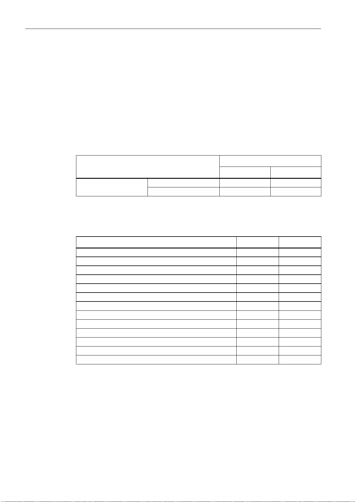
Table 1-1 Features of device versions
Number of output circuits
Function range
"Basic" "Enhanced"
1 Type 1 Type 3
2 Type 2 Type 4
The "Basic" and "Enhanced" function ranges differ as follows:
Table 1-2 "Basic" and "Enhanced" function ranges
"Basic" "Enhanced"
Number of functional devices at logic level 32 48
OR gates (inputs) 2 6
AND gates (inputs) no 6
Safe time function, switch-on and switch-off delay no yes
Function "button" no yes
Safety guard/module with debouncing no yes
Safety guard with lock no yes
Deactivation of functional devices yes yes
Reset of error condition yes yes
Diagnosis stop yes yes
Support of A/B technology for non-safe slaves yes yes
New functional devices (flip-flop, pulse on pos. edge, etc.) no yes
Dummy device (NOP) no yes
ASIMON V3 - Configuration software for AS-Interface safety monitor
8 Programming and Operating Manual, Edition 09/2008, GWA 4NEB 333 1558 02 DS 02
Page 9
New features in software version 2.1
Version 2.1 of the ASIMON configuration software includes the following new features:
• New monitoring device zero sequence detection
• Expansion of the output device door lock by means of delay time:
now optionally available with stop category 1 for the first OSSD
• Expansion of the output device door lock by means of zero-speed relay and delay time:
now optionally available with stop category 1 for the first OSSD
• New start device activation via standard slave (level-sensitive)
• New start device activation via monitor input (level-sensitive)
• New monitoring device operational switching by means of monitor input
• Expansion of monitoring device double channel dependent with debouncing for local
acknowledgement and startup test
• Expansion of monitoring device double channel independent for local acknowledgement
and startup test
• Incremental teaching of the code sequences
General Information
1.2 Version information
• Device index assignment
• Display of inverted icon when standard slave is inverted
• Number of simulated slaves can be selected
• Signalling of relay outputs and message outputs via the AS-Interface
Notice
The new functions of software version 2.1 can only be used in combination with AS-Interface
safety monitors of version 2.12 and higher.
New features in software version 3.0
In addition to the previous device types type 1 … type 4, also supported are two new device
types of version 3 (type 5 and type 6) of the AS-Interface safety monitor with safe AS-i out-
put:
Table 1-3 Features of device versions
Number of output circuits
Function range "Enhanced"
Output circuit 1 Output circuit 2
Type 5 Relay Safe AS-i output
2
Type 6 Relay Relay + safe AS-i output
ASIMON V3 - Configuration software for AS-Interface safety monitor
Programming and Operating Manual, Edition 09/2008, GWA 4NEB 333 1558 02 DS 02
9
Page 10

General Information
1.3 Explanation of symbols
Version 3.0 of the ASIMON configuration software includes the following new features:
• Support of safe AS-Interface transmission for controlling safe AS-Interface actuators
• Coupling of multiple safe AS-i networks through the function of the safety monitor as a
safe input slave (only for new device types with safe AS-i output)
• Multi-window technology with graphical printout of the configuration for each window
• Circuit diagram display of the logical links from left to right
• Extension of the device library and restructuring of the monitoring devices
• New monitoring device: 2-channel dependent with filtering
• Definition of user-specific functional devices
• Manual input of code sequences
• Availability of the standard out bits of the safe slaves for operational switching tasks
(acknowledgements, validations, unlocking, etc.)
Notice
The new functions of software version 3.0 can only be used in combination with AS-Interface
safety monitors of version 3.0 and higher.
Compatibility
With version 3.0 of the ASIMON configuration software, old configurations from version 1 and
version 2 can be opened, edited and saved.
Note
ASIMON configuration files have the extension *.ASI (version 1 AS-Interface safety moni-
tors), *.AS2 (version 2 AS-Interface safety monitors) or *.AS3 (version 3 AS-Interface safety
monitors).
1.3 Explanation of symbols
The symbols used in this manual are explained below.
Note
This symbol indicates text which contains important information.
ASIMON V3 - Configuration software for AS-Interface safety monitor
10 Programming and Operating Manual, Edition 09/2008, GWA 4NEB 333 1558 02 DS 02
Page 11

1.4 Definition of terms
Output switching element (safety output) of the AS-Interface safety monitor
Element activated by the logic of the monitor which is able to safely switch off the downstream
control elements. The output switching element may switch to or remain in the ON state only
when all components are functioning as intended.
Output circuit
Consists of the two logically connected output switching elements.
OSSD
The safe AS-Interface components and functional devices assigned to an output circuit of the
AS-Interface safety monitor. They are responsible for releasing the machine element which generates the hazardous movement.
Integrated slave
Component with which sensor and/or actuator functions are grouped together with the slave
into a unit.
General Information
1.4 Definition of terms
Configuration operation
Operating state of the safety monitor in which the configuration is loaded and checked.
Master
Component for data transmission which controls the logical and temporal behaviour on the
AS-Interface line.
Protective operation
Operating state of the safety monitor in which the sensors are monitored and the output switching elements are switched.
Safety output
See output switching element.
Safe output slave
Slave to which the safe ON or OFF state is transferred by the safety monitor and which controls
a safe actuator for switching off or shutting down while under voltage.
Safe input slave
Slave which reads in the safe ON or OFF state of the connected sensor or command device
and transmits it to the master or safety monitor.
Safe slave
Slave for connecting safe sensors, actuators and other devices.
Safety monitor
Component which monitors the safe slaves and the correct function of the network.
ASIMON V3 - Configuration software for AS-Interface safety monitor
Programming and Operating Manual, Edition 09/2008, GWA 4NEB 333 1558 02 DS 02
11
Page 12

General Information
1.5 Abbreviations
Slave
Component for data transmission; the master cyclically addresses this component by its
address. Only then does it generate an answer.
Standard slave
Slave for connecting non-safe sensors, actuators and other devices.
Synchronisation time
The maximum permissible temporal offset between the occurrence of two events which are
dependent on one another.
ON state
Switched on, logical "1", TRUE.
This state means that the device has agreed to validate the circuit, i.e. to activate the safe
switching outputs. Depending on the device type, various conditions must first be met.
OFF state
Switched off, logical "0", FALSE.
This state means that the device has not agreed to validate the circuit, i.e. it results in the
switching off of the safe switching outputs.
1.5 Abbreviations
AS-Interface
AOPD
EDM
PLC
Actuator Sensor Interface
Active Optoelectronic Protective Device
External Device Monitoring
Programmable Logic Control
ASIMON V3 - Configuration software for AS-Interface safety monitor
12 Programming and Operating Manual, Edition 09/2008, GWA 4NEB 333 1558 02 DS 02
Page 13

Installation of hardware and software 2
Installation of hardware and software
2.1 Hardware
2.1.1 Prerequisites
To configure the AS-Interface safety monitor via a PC, you will need:
• an AS-Interface safety monitor type 1 … type 6
• the interface cable for connecting the PC and AS-Interface safety monitor
• a PC or a laptop with the following minimum requirements:
-an Intel
(or compatible models, e.g. AMD
- a CD-ROM drive for installing from CD-ROM
- a mouse (recommended)
- a free RS 232 (serial) interface with 9-pin Sub-D connection
Notice
®
processor at Pentium® level
®
or Cyrix®)
When using a USB-RS 232 interface converter or a serial interface card, communication problems may occur with the safety monitor.
2.1.2 Connection between the AS-Interface safety monitor and the PC
Note
The connection of the AS-Interface safety monitor to the PC is described here only briefly. Detailed information can be found in the operating manual for the AS-Interface safety monitor.
To configure the AS-Interface safety monitor with ASIMON, you must connect your PC and the
AS-Interface safety monitor using the serial interface cable (available as accessory).
Caution
Use only the interface cable which is available as an accessory. The use of a different cable
may lead to data loss or damage to the connected AS-Interface safety monitor!
ASIMON V3 - Configuration software for AS-Interface safety monitor
Programming and Operating Manual, Edition 09/2008, GWA 4NEB 333 1558 02 DS 02
13
Page 14

Installation of hardware and software
2.2 Software
To connect, plug the interface cable end with the RJ45 connector into the 'CONFIG' socket on
the front of the AS-Interface safety monitor and the other end with the 9-pin Sub-D socket connector to a free COM port (serial RS232 interface) on your PC.
Notice
If the connection between the AS-Interface safety monitor and the PC is already established
when the PC is started, the mouse cursor may move erratically about the screen.
Remedy:
• When starting the PC, unplug the connection cable between the PC and the safety monitor.
• Change the start behaviour of the PC (see user documentation for the PC or that of the
operating system manufacturer).
2.2 Software
2.2.1 System requirements
The following system requirements are necessary for the AS-Interface safety monitor configuration software:
- at least 32 MB free main memory (RAM)
- at least 32 MB free hard disk memory
-Microsoft
®
Windows 95/98/ME/NT/2000/XP/Vista® as operating system
2.2.2 Installation
To install the configuration software, you need the installation CD-ROM.
Upon execution of the setup program setup.exe on the installation CD-ROM, a self-explanatory installation routine is started. After the installation, the program is ready to be started.
With an update installation, the setup program checks whether ASIMON version 2.x is already
installed on the PC. If a previous installation is detected, the setup program offers the option
of replacing the existing installation with version 3.0 or, as an alternative, creating a second
subfolder.
ASIMON V3 - Configuration software for AS-Interface safety monitor
14 Programming and Operating Manual, Edition 09/2008, GWA 4NEB 333 1558 02 DS 02
Page 15

First steps 3
First steps
Note
Connect the interface cable to the PC and the safety monitor as described in chapter 2.1.2.
Switch on the power supply for the safety monitor before starting the configuration software.
Data transmission is otherwise not possible.
However, even if the safety monitor is not connected to the PC, you may still define device configurations and save them on your PC or edit a previously stored configuration
ASIMON V3 - Configuration software for AS-Interface safety monitor
Programming and Operating Manual, Edition 09/2008, GWA 4NEB 333 1558 02 DS 02
15
Page 16
First steps
4
2
3
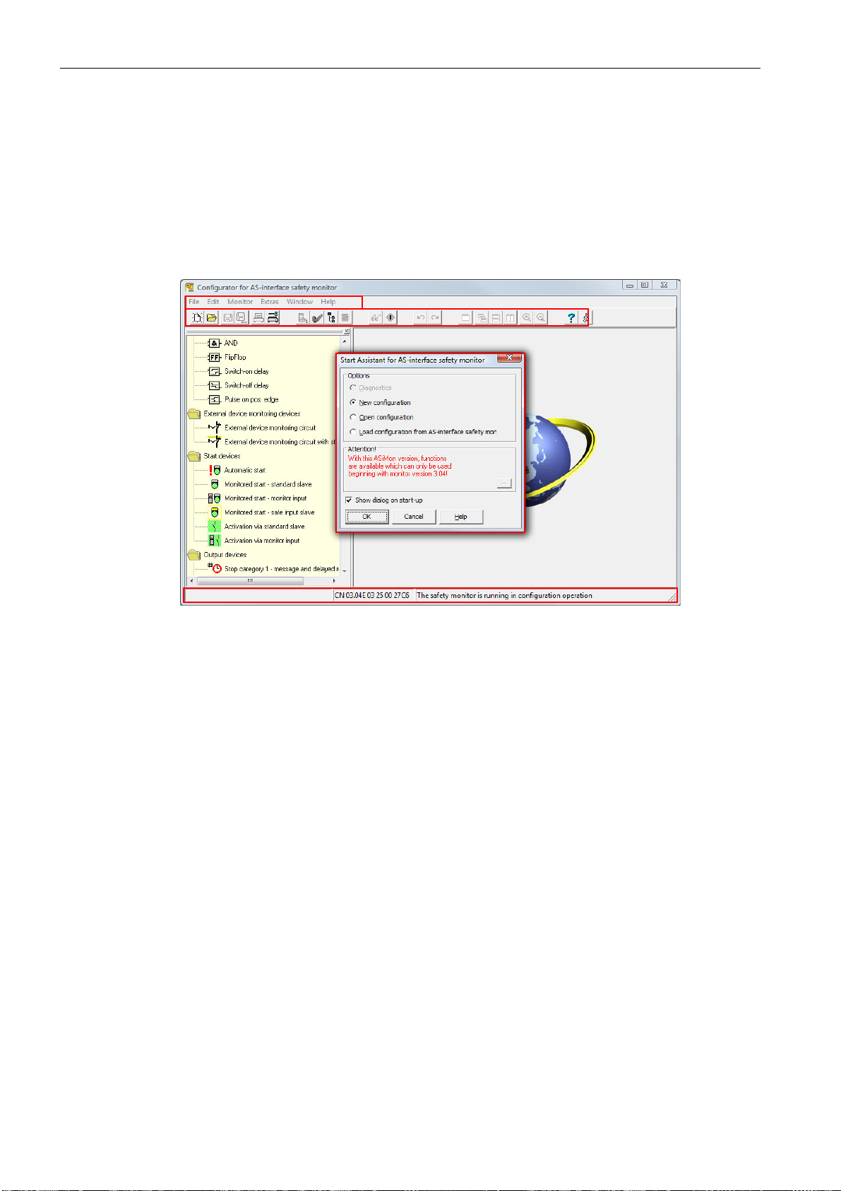
1
1 Start Assistant window
2 Menu bar
3 Toolbar
4 Status/Info bar
3.1 Launching the program
3.1 Launching the program
To start the configuration software for the AS-Interface safety monitor, select from the Start
menu the ASIMON item, which is located in the program folder you specified during installati-
on.
After the program has started, the window with the ASIMON configuration software user interface appears on the screen. When the program is started, the Start Assistant is called up to
guide you through the first steps following program startup.
Figure 3-1 User interface of the ASIMON configuration software after starting the software
16 Programming and Operating Manual, Edition 09/2008, GWA 4NEB 333 1558 02 DS 02
ASIMON V3 - Configuration software for AS-Interface safety monitor
Page 17
Start Assistant
First steps
3.1 Launching the program
Note
In order to query the diagnostic information, the connected AS-Interface safety monitor must
be in protective operation.
If a connection to the AS-Interface safety monitor cannot be established on program startup
(no AS-Interface safety monitor connected, connected to wrong interface etc.) or if the connected AS-Interface safety monitor is in configuration operation, the Diagnostics option is deactivated.
In this case, it is only possible to create a new configuration, load and edit a configuration which
has been stored on a data carrier or to search for errors (see chapter 6.2 "Troubleshooting and
error rectification").
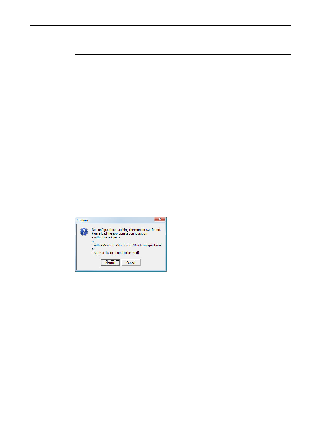
Option Diagnostics
When you select the Diagnostics option, first a window opens with the following query. By
clicking Neutral, the diagnostic information of the connected AS-Interface safety monitor is
queried, even if no configuration is loaded in ASIMON.
Note
Querying the diagnostic information of an unknown configuration can take several minutes, as
the configuration of the connected AS-Interface safety monitor must be reconstructed in ASI-
MON. In this way you can load an unknown configuration without needing to exit protective
operation.
Figure 3-2 Query with the Diagnostics option
Next, the Diagnostics window opens (see chapter 6.1 "Diagnostics").
ASIMON V3 - Configuration software for AS-Interface safety monitor
Programming and Operating Manual, Edition 09/2008, GWA 4NEB 333 1558 02 DS 02
17
Page 18

First steps
3.1 Launching the program
Option New configuration
With the New configuration option, you can create a completely new configuration for the
AS-Interface safety monitor. First, you must enter the base data for the new configuration in
the Information about monitor and bus window. This window is displayed automatically.
Note
The Information about monitor and bus window can be called up at any time. To do this, on
the Edit menu, select the Information about monitor and bus… menu item or click the
button.
Note
If a valid configuration has been loaded to or from an AS-Interface safety monitor, the time at
which the current configuration in the program was transmitted to the AS-Interface safety monitor is shown in the Download time window area.
In the Information monitor tab, you must enter a title for the configuration, select the operating mode, specify whether a safe AS-i output exists and specify the "Basic" or "Enhanced"
function range of the AS-Interface safety monitor.
Figure 3-3 Information about monitor and bus window, Information monitor tab
Configuration title
In this field, enter a title for the new configuration. The title may contain up to 63 characters.
ASIMON V3 - Configuration software for AS-Interface safety monitor
18 Programming and Operating Manual, Edition 09/2008, GWA 4NEB 333 1558 02 DS 02
Page 19
Operating mode
First steps
3.1 Launching the program
You can select from three operating modes:
•one OSSD
for AS-Interface safety monitors of type 1 or type 3 with 1 OSSD (1 redundant safe relay
output)
• two independent OSSDs
for AS-Interface safety monitors of type 2 or type 4 with 2 independently functioning
OSSDs (2 redundant safe relay outputs)
Select this operating mode when you would like to configure two completely independent
shutdown modes.
• two dependent OSSDs
for AS-Interface safety monitors of type 2 or type 4 with 2 OSSDs (2 redundant safe relay
outputs) in which the second OSSD is dependent on the first (see chapter 4.3.5 "Output
devices").
Special switch-off functions are available in this operating mode.
Note
Prior to a subsequent change of operating mode, determine whether this operating mode is
compatible with the AS-Interface safety monitor type which you are using (see table 3-1).
AS-i output
Here, you specify whether the AS-Interface safety monitor which is to be configured has a safe
AS-i output and whether it is linked to a safe AS-i input. Furthermore, you also specify here
whether a safe actuator is connected or whether the AS-Interface safety monitor functions as
a safe input slave in a coupled AS-Interface network. In this case, you must specify the
AS-Interface address of the actuator or assign the safe input slave an AS-Interface address.
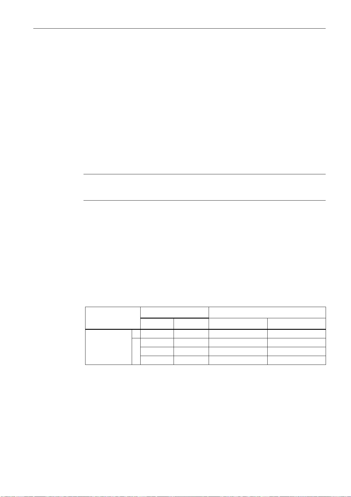
Function range
Here, enter the function range of the AS-Interface safety monitor which is to be configured. The
following table shows how the six device types of the AS-Interface safety monitor differ from
one another:
Table 3-1 Features of device versions
Function range Type
"Basic" "Enhanced" Output circuit 1 Output circuit 2
1 Type 1 Type 3 Relay –
Number of out-
put circuits
Type 2 Type 4 Relay Relay
2
– Type 5 Relay AS-i output
– Type 6 Relay Relay + AS-i output
ASIMON V3 - Configuration software for AS-Interface safety monitor
Programming and Operating Manual, Edition 09/2008, GWA 4NEB 333 1558 02 DS 02
19
Page 20
First steps
3.1 Launching the program
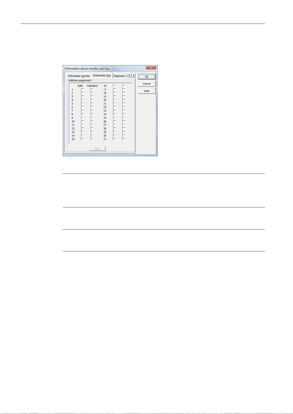
On the Information bus tab, you must enter the AS-Interface bus addresses of the used standard slave and the safety-oriented AS-Interface slaves which are present in this AS-Interface
network.
Figure 3-4 Information about monitor and bus window, Information bus tab
Notice
If you would like to operate two or more AS-Interface safety monitors on the same AS-Interface
bus, you must enter for all AS-Interface safety monitors all safe slaves on this AS-Interface bus
in the Information bus tab even when they are not monitored by the given AS-Interface safety
monitor.
With the Find button, you can also search the AS-Interface bus for slaves when the AS-Inter-
face safety monitor is in configuration operation.
Note
The AS-Interface slaves found when searching the AS-Interface bus are first all listed in the
Information bus tab as standard. You must then manually assign each as safe/standard!
If you clicked the Simulate slaves checkbox on the Diagnosis / Service tab, two or four bus
addresses are automatically assigned for the simulated slaves and the corresponding checkbox deactivated. In order to be able to activate Simulate slaves, the one or three addresses
which follow the monitor address must be free.
ASIMON V3 - Configuration software for AS-Interface safety monitor
20 Programming and Operating Manual, Edition 09/2008, GWA 4NEB 333 1558 02 DS 02
Page 21
First steps
3.1 Launching the program
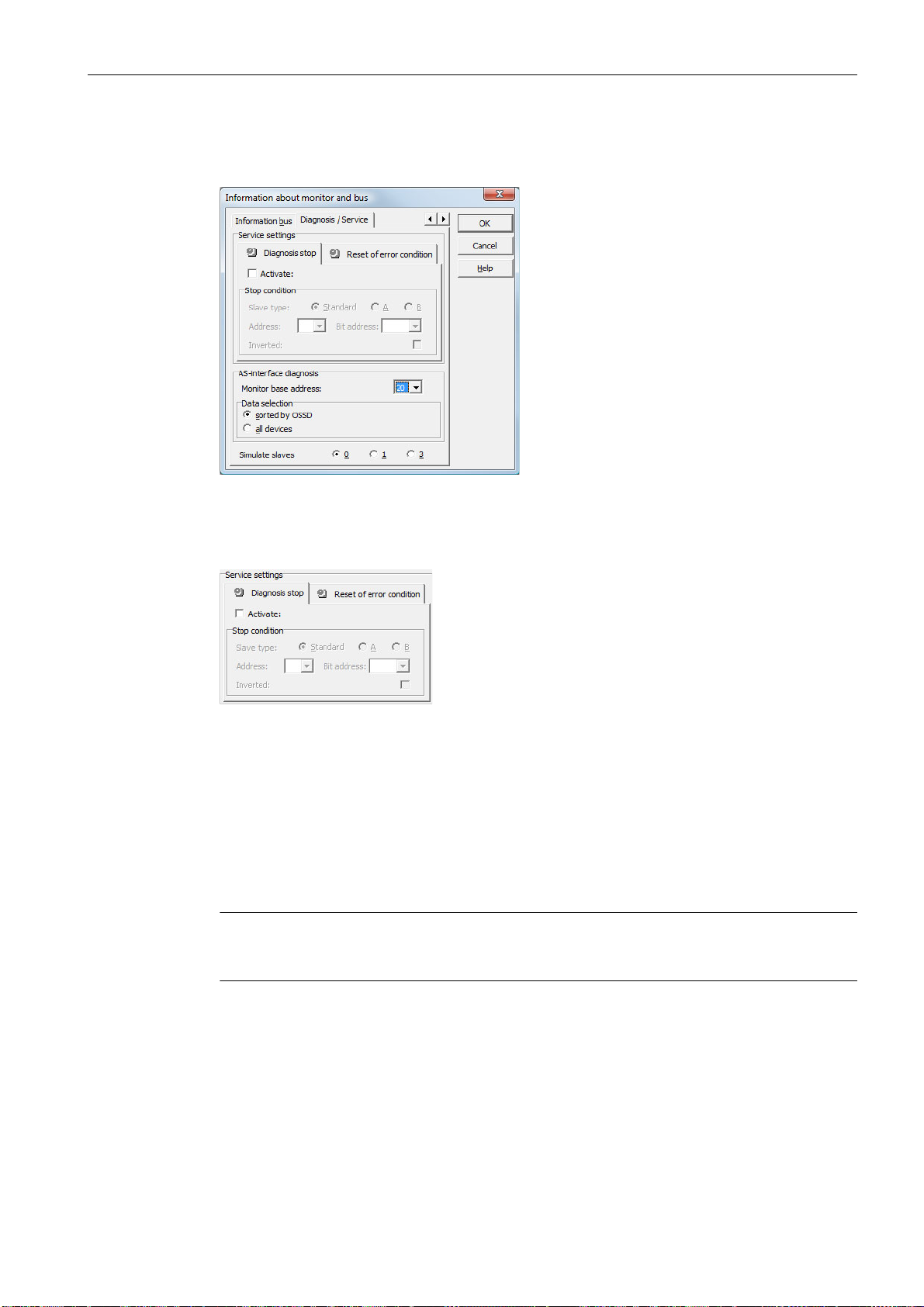
On the Diagnosis / Service tab, you can make service settings for Diagnosis stop and for Reset of error condition as well as configure the diagnostics via the AS-Interface bus.
Figure 3-5 Information about monitor and bus window, Diagnosis / Service tab
Service settings, Diagnosis stop sub-tab
Figure 3-6 Diagnosis stop sub-tab of the Diagnosis / Service tab
The Diagnosis stop function is activated by clicking the Activate: checkbox. This function is
used when a stop condition is fulfilled (specified AS-Interface standard/A/B slave is in the ON
state) to keep the devices in a ready state (diagnostics LED yellow, waiting for confirmation).
This does not occur with activated local acknowledgement. The diagnosis stop is level-sensitive and is deactivated if the specified standard/A/B slave has no bus communication.
This function is very useful, for example, for detecting during very brief switch-off actions which
device, and, thus, which safe input slave caused the switch-off.
Note
For additional information on calling up diagnostic information see chapter "Diagnostics and
error handling" and chapter "Diagnostics via AS-Interface".
ASIMON V3 - Configuration software for AS-Interface safety monitor
Programming and Operating Manual, Edition 09/2008, GWA 4NEB 333 1558 02 DS 02
21
Page 22
First steps
3.1 Launching the program
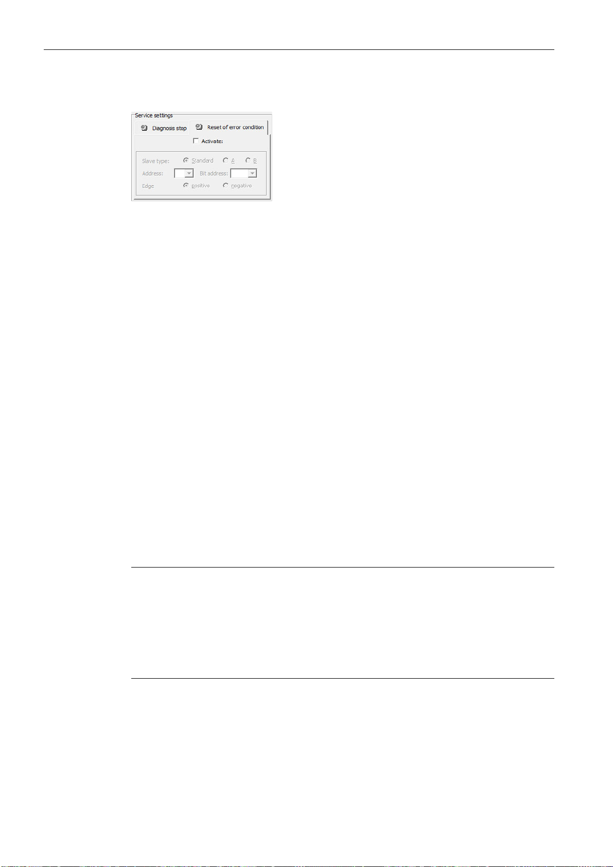
Service settings, Reset of error condition sub-tab
Figure 3-7 Reset of error condition sub-tab of the Diagnosis / Service tab
By selecting the Activate: checkbox, the global reset of error conditions via one of the standard/A/B slaves connected to the AS-Interface bus is activated.
If a device detects an error, the AS-Interface safety monitor enters the error state. The error
state is locked (error lock). With versions of the AS-Interface safety monitor before 2.0, the error state can be rectified only by resetting the AS-Interface communication or by resetting the
AS-Interface safety monitor by switching off and then switching back on the AS-Interface safety
monitor or by pressing the Service button on the AS-Interface safety monitor.
As of version 2.0 of the AS-Interface safety monitor, it is possible to differentiate the reset of
error conditions (Reset). Reset of error condition can be activated by an AS-Interface standard/
A/B slave, e.g. a button, and acts only on a device level. Thus, the complete safety monitor is
not reset, but rather only the device locked in the error. For a safety monitor with two independent OSSDs, therefore, only that OSSD is reset in which the device locked in the error is configured.
AS-Interface diagnosis
Monitor base address
You can assign an AS-Interface bus address for the AS-Interface safety monitor. In this case,
it is possible to query diagnostic information about the AS-Interface bus from your AS-Interface
master (e.g. the PLC). If you do not assign an AS-Interface bus address, the AS-Interface safety monitor functions strictly as a "listener", i.e. only as a monitor on the bus. It is not possible
to communicate with the safety monitor via AS-Interface in this case.
For assigned monitor base addresses, you can set under Data selection whether the diagnostic data are to be output via AS-Interface sorted by OSSD or are to be left unsorted (all
devices) (see chapter 7).
Note
When performing diagnostics via the AS-i, the PLC is informed of the indices of the devices
which are switched off. Previously, if a device was added to or deleted from the configuration,
all subsequent indices were shifted. As a result, it was necessary for the user to modify the
diagnostics program in the PLC.
In the Edit menu of ASIMON version 2.1, you can now use the Device index assignment
menu item to freely assign the diagnosis indices to the devices for AS-Interface diagnostics
(see chapter 7.2 "Assignment of the AS-Interface diagnosis indices").
ASIMON V3 - Configuration software for AS-Interface safety monitor
22 Programming and Operating Manual, Edition 09/2008, GWA 4NEB 333 1558 02 DS 02
Page 23
First steps
3.1 Launching the program
Simulate slaves
If less than four safe or unsafe AS-Interface slaves are connected to the AS-Interface bus, you
must set Simulate slaves to zero in order for the AS-Interface safety monitor to function
correctly.
The number of simulated slaves can be 1 (for large AS-Interface networks) or 3 (for small
AS-Interface networks).
Note
If Simulate slaves is set unequal to zero, either 1 or 3 additional AS-Interface slaves are
simulated internally. These slaves are automatically assigned the first or first three bus
address(es), respectively, which follow on the AS-Interface safety monitor.
If the Simulate slaves function is activated (number of simulated slaves: 1 or 3), the state of
the relay- and message outputs can be queried by the AS-Interface master (PLC) via the
AS-Interface at monitor base address+1, data bits D3 … D0. Bit state 0 identifies an inactive
output, bit state 1 an active output, corresponding to the substitute value in the process image
of the AS-Interface master.
Data bit Content
D0 State of relay output 1
D1 State of message output 1
D2 State of relay output 2
D3 State of message output 2
According to this, the AS-Interface safety monitor occupies a different number of bus
addresses in the AS-Interface network:
Number of
occupied bus
addresses
0 No bus address was assigned to the AS-Interface safety monitor. No communi-
cation and, thus, no diagnostics possible via AS-Interface with the safety monitor.
1 One bus address was assigned to the AS-Interface safety monitor. Diagnostics
possible via AS-Interface with the safety monitor. Number of simulated slaves
equal to 0.
2 One bus address was assigned to the AS-Interface safety monitor. Diagnostics
possible via AS-Interface with the safety monitor. Number of simulated slaves
equal to 1. State of relay- and message outputs can be accessed via AS-Interface at monitor base address+1 (monitor version 2.12 and higher).
4 One bus address was assigned to the AS-Interface safety monitor. Diagnostics
possible via AS-Interface with the safety monitor. Number of simulated slaves
equal to 3. State of relay- and message outputs can be accessed via AS-Interface at monitor base address+1 (monitor version 2.12 and higher).
Meaning
ASIMON V3 - Configuration software for AS-Interface safety monitor
Programming and Operating Manual, Edition 09/2008, GWA 4NEB 333 1558 02 DS 02
23
Page 24
First steps
3.1 Launching the program
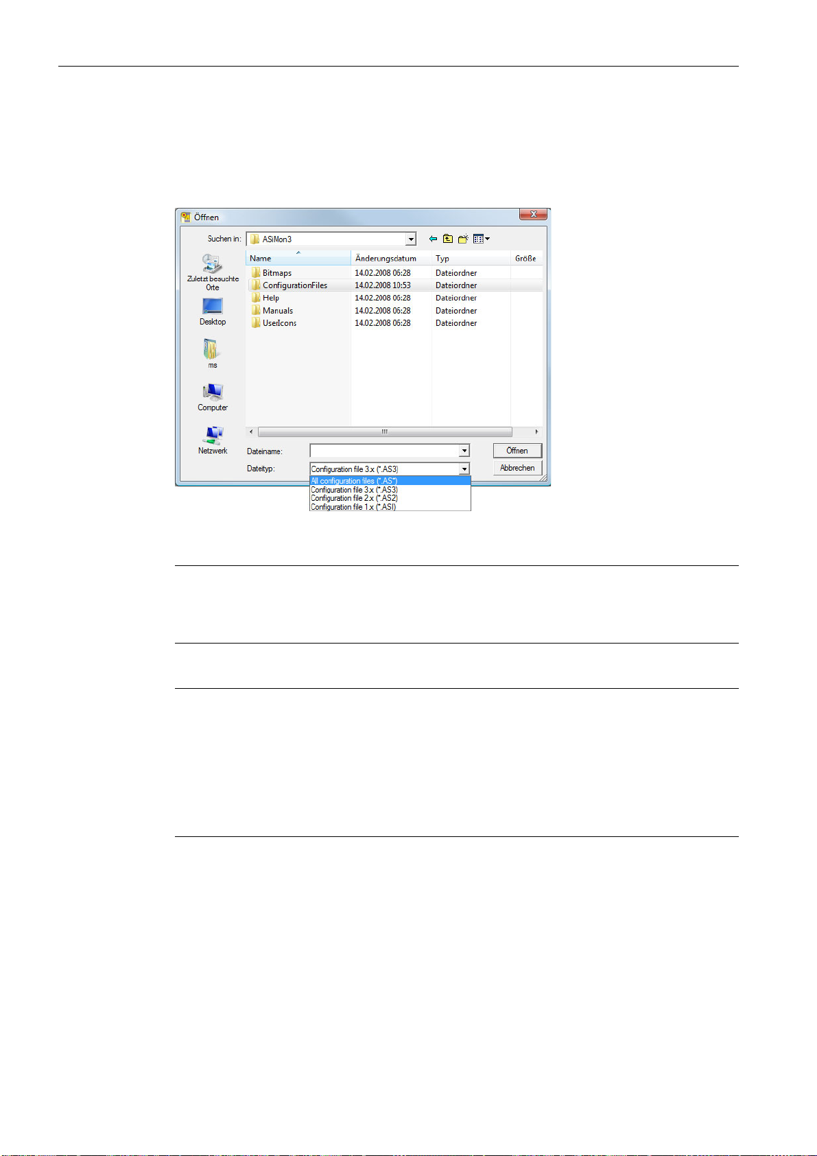
Option Open configuration
With the Open configuration option, you can open an existing configuration file (*.asi) which
was previously stored on a data carrier for purposes of editing or transmitting to an AS-Interface safety monitor.
Figure 3-8 Opening a stored configuration file
Note
ASIMON configuration files have the extension *.ASI (version 1 AS-Interface safety moni-
tors), *.AS2 (version 2 AS-Interface safety monitors) or *.AS3 (version 3.x AS-Interface
safety monitors).
Option Load configuration from AS-Interface safety monitor
Note
If a connection to the AS-Interface safety monitor cannot be established on program startup
(no AS-Interface safety monitor connected, connected to wrong interface etc.) or if the connected AS-Interface safety monitor is in protective operation, the Load configuration from AS-In-
terface safety monitor option is deactivated.
In this case, it is only possible to create a new configuration, load and edit a configuration which
has been stored on a data carrier or to search for errors (see chapter 6.2 "Troubleshooting and
error rectification").
When you select the Load configuration from AS-Interface safety monitor option, the configuration of the connected AS-Interface safety monitor is queried and displayed in the main
program window.
Checkbox Show dialog on startup
When this checkbox is activated, the Start Assistant is called up each time the ASIMON pro-
gram is started. If you do not wish to use this program feature, simply deactivate this checkbox
and the Start Assistant will no longer automatically be opened on program startup.
On the Extras menu under Use Start Assistant, you can reactivate or deactivate the automatic call of the Start Assistant on program startup at any time.
ASIMON V3 - Configuration software for AS-Interface safety monitor
24 Programming and Operating Manual, Edition 09/2008, GWA 4NEB 333 1558 02 DS 02
Page 25
3.2 Description of the user interface
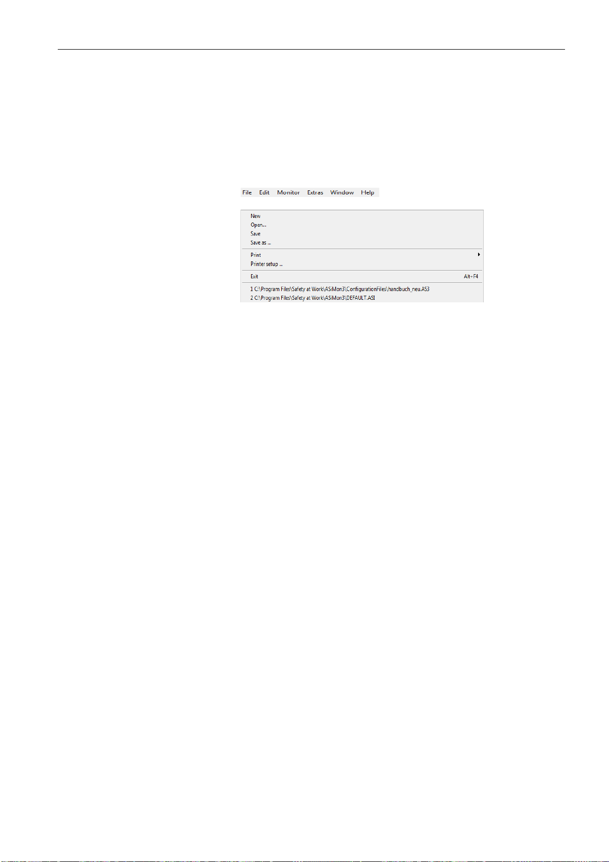
Main menu bar
File menu
3.2.1 The menu bar
Menu overview
Figure 3-9 Menu overview 1
First steps
3.2 Description of the user interface
ASIMON V3 - Configuration software for AS-Interface safety monitor
Programming and Operating Manual, Edition 09/2008, GWA 4NEB 333 1558 02 DS 02
25
Page 26
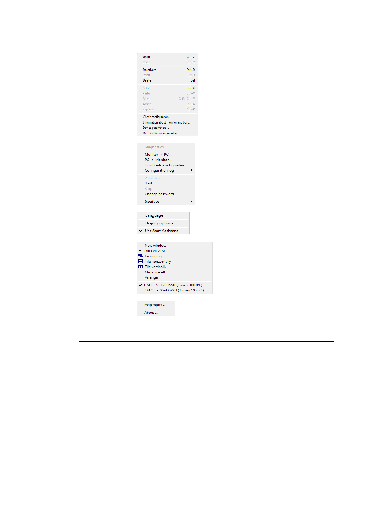
First steps
Edit menu
Monitor menu
Extras menu
Help menu
Window menu
3.2 Description of the user interface
Figure 3-10 Menu overview 2
Note
Depending on the program state, particularly when no connection to an AS-Interface safety
monitor exists, not all menu commands are available.
ASIMON V3 - Configuration software for AS-Interface safety monitor
26 Programming and Operating Manual, Edition 09/2008, GWA 4NEB 333 1558 02 DS 02
Page 27
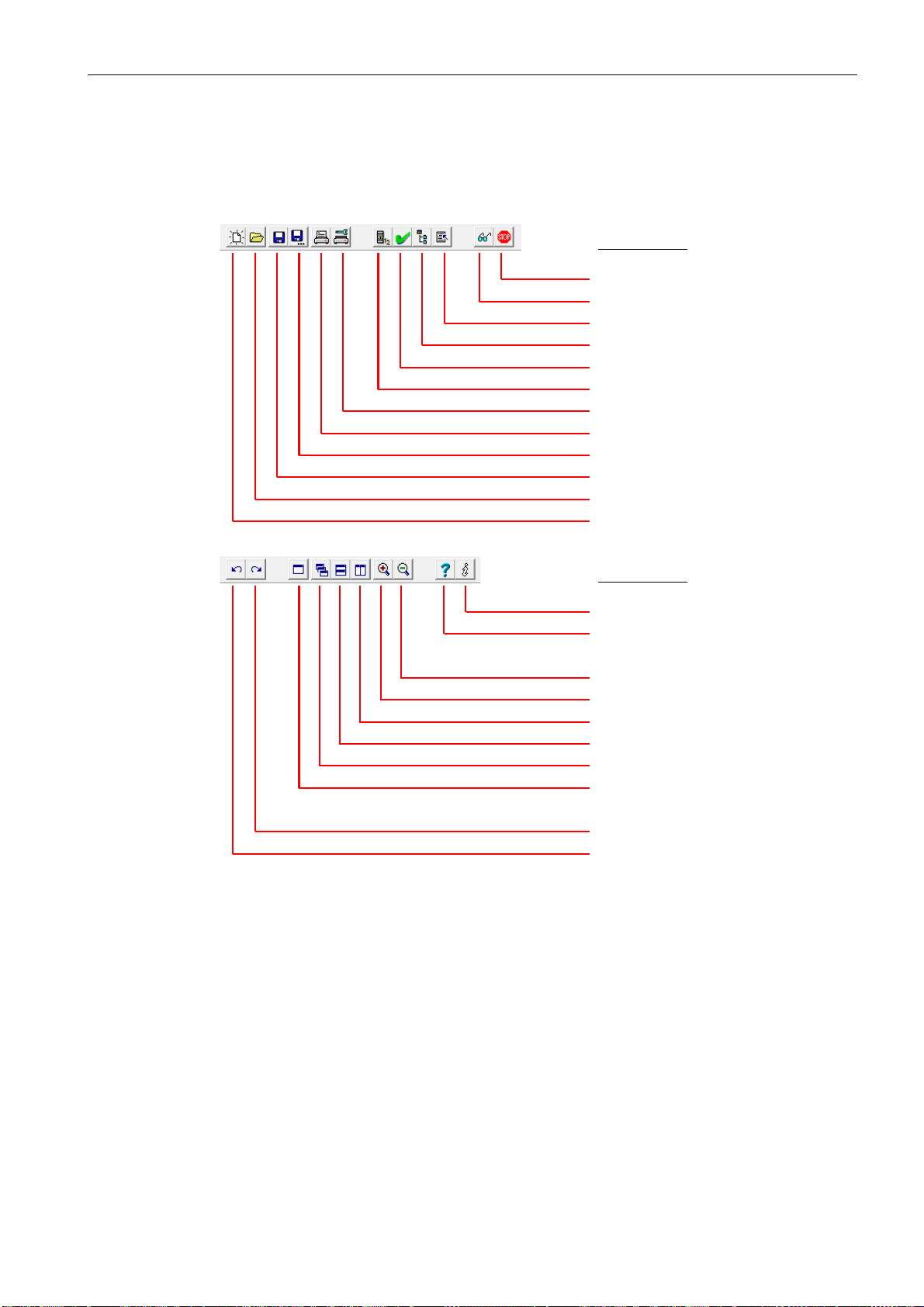
3.2.2 The toolbar
Menu command
Monitor –> Start/Stop
Monitor –> Diagnostics
Device index assignment
Display options…
Check configuration
Information about monitor and bus…
File –> Printer setup…
File –> Print
File –> Save as…
File –> Save
File –> Open…
File –> New
Menu command
Help –> About…
Help –> Help topics…
Reduce (zoom out)
Enlarge (zoom in)
Windows tiled vertically
Windows tiled horizontally
Cascading windows
New window
Redo
Undo
As in other Windows® programs, you can use the buttons located in the toolbar to directly execute important functions without accessing the menu.
First steps
3.2 Description of the user interface
Figure 3-11 Toolbar
ASIMON V3 - Configuration software for AS-Interface safety monitor
Programming and Operating Manual, Edition 09/2008, GWA 4NEB 333 1558 02 DS 02
27
Page 28
First steps
Left side:
Help information
Right side:
Status and error information
Centre:
Monitor version
(in configuration operation)
3.2 Description of the user interface
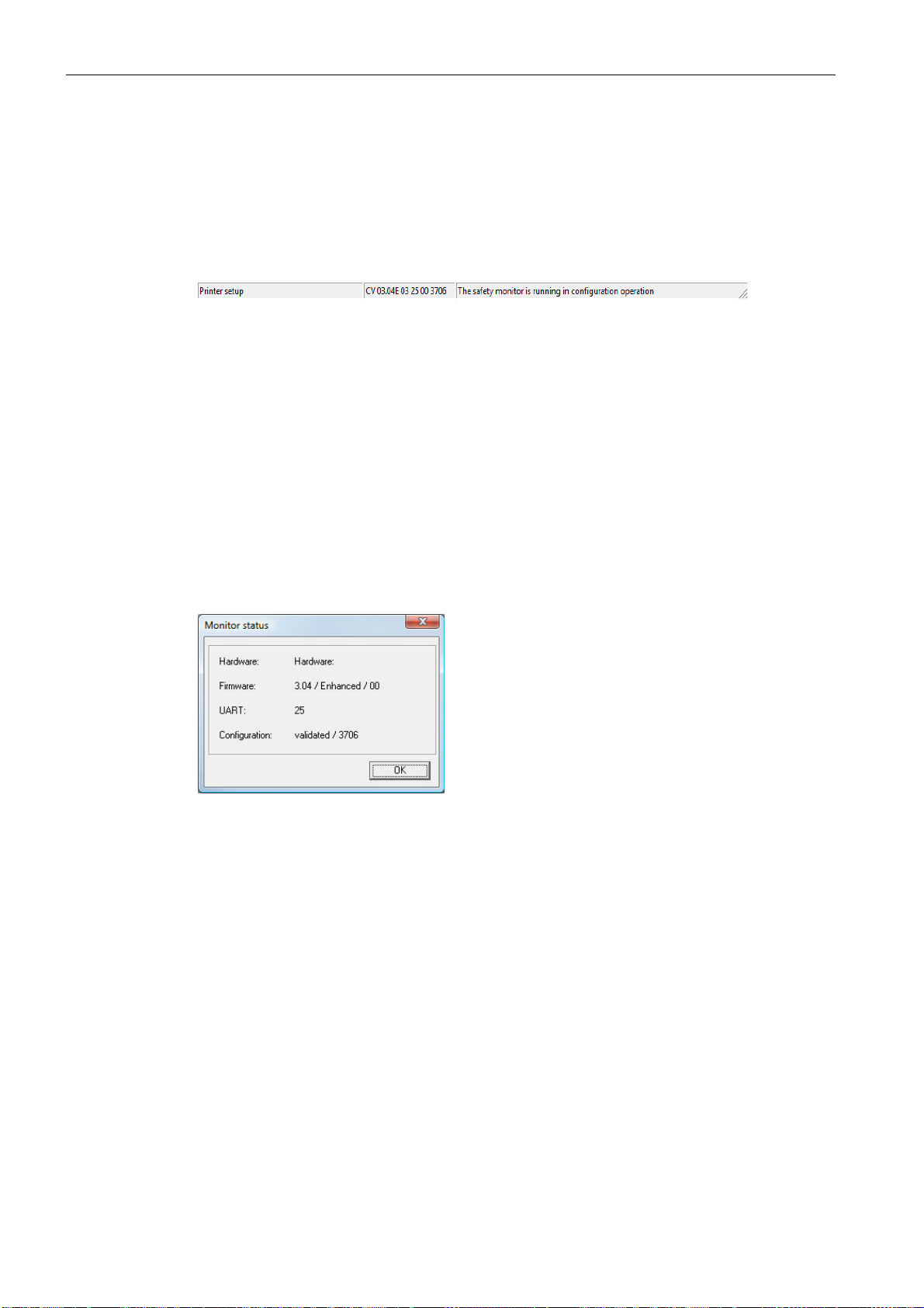
3.2.3 The status/info bar
The status/info bar provides valuable information regarding program operation and alerts you
of problems and errors during program execution.
Figure 3-12 Status/info bar
The information on the monitor version in the centre has the following meaning:
CV - Configuration Validated
03.00E - safety monitor version
03 - number of safety outputs (00 = type1/type3, 01 = type2/type4, 02 = type5, 03 = type6)
25 - UART version
00 - free
90C4 - 4-digit code
Click the status/info bar in configuration operation to open a window with status information on
the connected AS-Interface safety monitor.
Figure 3-13 Monitor status window
28 Programming and Operating Manual, Edition 09/2008, GWA 4NEB 333 1558 02 DS 02
ASIMON V3 - Configuration software for AS-Interface safety monitor
Page 29
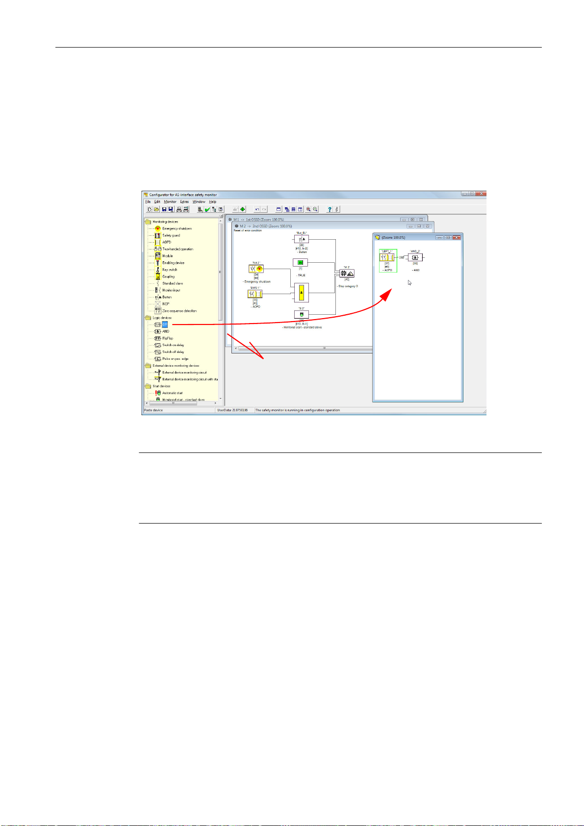
3.2.4 The work area
Icon library
window
(docked)
1st and 2nd OSSD
windows
Active window for
preprocessing or user
device
Work area
Insert a device by
means of
drag&drop
The configuration of an AS-Interface safety monitor with the ASIMON software is performed
graphically and interactively. Using a library of icons representing devices (left window, docked), you can select the safe AS-Interface slaves which are to be monitored as well as other
functional devices and assemble a configuration with them.
The configuration (or parts thereof) are represented in a circuit diagram display as logically
linked devices from left to right in the windows.
First steps
3.2 Description of the user interface
Figure 3-14 Work area with windows
Note
You can switch between the new circuit diagram display (beginning with software version 3)
and the old tree structure display.
To do this, select the Extras –> Display options menu item or press <Ctrl> + <S> or
<Ctrl> + <T>.
The sizes of the individual windows can be adjusted to meet your needs as in other Windows®
programs.
ASIMON V3 - Configuration software for AS-Interface safety monitor
Programming and Operating Manual, Edition 09/2008, GWA 4NEB 333 1558 02 DS 02
29
Page 30

First steps
3.2 Description of the user interface
Window
The work area may contain any number of windows. The functions in the Window menu are
available for arranging the windows.
As in the past, a device is inserted from the icon library using drag&drop. All windows are initially equal. A window becomes an OSSD window by inserting an output device. If all OSSDs
are defined by a separate configuration window, no further output devices can be inserted in
other windows.
In addition to the OSSD windows, which contain the actual configuration for an AS-Interface
safety monitor, you can use other windows to form substructures (sub-devices) and create
user devices.
Note
The Preprocessing window area familiar from previous software versions no longer exists.
For AS-Interface safety monitors of types 1 and 2 with "Basic" function range, the only possible
logic device available for the linking of two monitoring or system devices is the logic OR function.
In the 1st OSSD and 2nd OSSD windows, the monitoring devices (safe AS-Interface slaves),
start devices, external device monitoring devices, system devices, logic devices and output devices are grouped into the desired configuration and linked to one another using the logical
AND function. Very complex functions can be created in this way.
Operation
Note
The view in the window is updated by pressing the <F5> key; i.e. the window contents are redrawn on the screen.
To paste devices from the icon library into the other windows, as well as to edit, delete, move
and copy devices between the windows, various options are available depending on your personal preference:
• With the mouse:
-by drag&drop from the icon library:
click device with the left mouse button, keep mouse button pressed, and move the device. Simultaneously press the <Ctrl> key for further options:
- If devices are pulled from the selection list to a window with the mouse, the device is
automatically inserted. If the <Ctrl> key is pressed before the mouse button is released, the selected device replaces the device previously present at this position.
•using the right mouse button:
click device with right mouse button and select action from the pop-up menu. If necessary,
change to another window area, click the right mouse button again and select action.
• using menu commands:
click device with the left mouse button, on the Edit menu select one of the commands
Deactivate, Invert, Delete, Select, Paste, Move, Assign or Replace. If necessary, chan-
ge to another window area, click OSSD, Preprocessing, device or position and again click
a command on the Edit menu.
ASIMON V3 - Configuration software for AS-Interface safety monitor
30 Programming and Operating Manual, Edition 09/2008, GWA 4NEB 333 1558 02 DS 02
Page 31

First steps
1 2 3
Click the output of a
device with the left
mouse button and
hold down.
Pull the connection line ("rubber band")
to the input on the desired device and
release the left mouse button.
Device is
assigned to
the link
3.2 Description of the user interface
• With the keyboard:
- with the <Tab> key: change window areas.
- with the arrow keys: select circuit, device or position.
- execute actions using the following keyboard commands:
<Ctrl> + <D> = Activate/Deactivate
<Ctrl> + <I> = Invert
<Delete> = Delete
<Ctrl> + <C> = Select
<Ctrl> + <V> = Paste
<Shift> + <Ctrl> + <V> = Move
<Ctrl> + <A> = Assign
<Ctrl> + <R> = Replace
In addition to the devices themselves, you can also change the connection lines of the devices
(and thus the device assignment).
Figure 3-15 Device assignment by creating/moving connection lines
Note
If a monitoring device from an OSSD is to be assigned to a link in a new (non-OSSD window),
the link must first be created. After creating the link, select the monitoring device in the OSSD
(<Ctrl> + <C>) and assign it to the logic device in the new window (click the logic device and
press <Ctrl> + <A>).
ASIMON V3 - Configuration software for AS-Interface safety monitor
Programming and Operating Manual, Edition 09/2008, GWA 4NEB 333 1558 02 DS 02
31
Page 32

First steps
3.2 Description of the user interface
Display options…
You can set with which informational content the devices are to be displayed in the windows
and the size in which the windows are printed out as graphics. To do this, on the Extras menu,
select the Display options… menu item or click the button.
Figure 3-16 Display options - Display
In addition, you can globally set the type of configuration display for all windows here:
• new circuit diagram display (beginning with software version 3) –> tick in Circuit diagram
display.
• old tree structure display –> no tick in Circuit diagram display.
Figure 3-17 Example: Old tree structure display
The Horizontal raster and Vertical raster values determine the distances between the individual devices in the circuit diagram display. By setting the tick for Standard setting, the default values (h:100, v:50) for the device raster are restored.
ASIMON V3 - Configuration software for AS-Interface safety monitor
32 Programming and Operating Manual, Edition 09/2008, GWA 4NEB 333 1558 02 DS 02
Page 33

First steps
3.2 Description of the user interface
You can specify the scaling for printing the active window as a graphic on the Printer tab.
Figure 3-18 Display options - Printer
ASIMON V3 - Configuration software for AS-Interface safety monitor
Programming and Operating Manual, Edition 09/2008, GWA 4NEB 333 1558 02 DS 02
33
Page 34

First steps
3.3 Program settings
3.3 Program settings
3.3.1 Setting the program language
The user interface of the ASIMON configuration software supports the following languages:
• German • Spanish • Swedish
• English • Italian
• French • Japanese
To change the language of the user interface, select on the Extras menu under the Language
menu item the desired language. The program does not need to be restarted after changing
the language.
Figure 3-19 Setting the program language
Note
The Japanese characters can be displayed only if the operating system supports such
characters.
ASIMON V3 - Configuration software for AS-Interface safety monitor
34 Programming and Operating Manual, Edition 09/2008, GWA 4NEB 333 1558 02 DS 02
Page 35

3.3.2 Selecting the serial interface
When starting the program, ASIMON asks if and at which PC serial interface (COM-port) an
AS-Interface safety monitor is connected. If the connection between the PC and safety monitor
is established only after the ASIMON software has been started, you must manually select the
correct COM port in the program. Otherwise, no connection can be established to the AS-Interface safety monitor.
The transmission parameters for serial communication with the AS-Interface safety monitor
are automatically set by ASIMON.
First steps
3.3 Program settings
Figure 3-20 Selecting the serial interface
Notice
When using a USB-RS 232 interface converter or a serial interface card, the intermediate
buffering of data may cause communication problems with the safety monitor.
ASIMON V3 - Configuration software for AS-Interface safety monitor
Programming and Operating Manual, Edition 09/2008, GWA 4NEB 333 1558 02 DS 02
35
Page 36

ASIMON V3 - Configuration software for AS-Interface safety monitor
36 Programming and Operating Manual, Edition 09/2008, GWA 4NEB 333 1558 02 DS 02
Page 37

Configuring the AS-Interface safety monitor 4
Configuring the AS-Interface safety monitor
The AS-Interface safety monitor is a universally usable protective device and can, therefore,
be configured for a very wide range of applications.
4.1 Function of the AS-Interface safety monitor
The functional task of the AS-Interface safety monitor is to continuously specify the state(s) of
the OSSD(s) in accordance with the configuration specified by the user based on the states of
the configured devices and to activate or deactivate the assigned safe switching outputs or
safe actuators.
The ASIMON software automatically arranges the devices in the respective windows during
configuration.
Each device can take on two states:
ON state (switched on, logical "1")
This state means that the device has agreed to validate the circuit, i.e. to activate the safe
switching outputs. Depending on the device type, various conditions must first be met.
OFF state (switched off, logical "0")
This state means that the device has not agreed to validate the circuit, i.e. it results in the
switching off of the safe switching outputs.
In the first step of the evaluation, the states of all monitoring, logic and EDM devices are linked
to one another by means of a global logic AND function, i.e. only when all configured monitoring, logic and EDM devices have the ON state is the result of the AND function equal to ON.
In principle, the device states are evaluated in the same way as in an electrical safety circuit in
which all safety switch elements are connected in series and validation is possible only when
all contacts are closed.
In the second step, the start devices which determine the startup behaviour of the OSSD are
evaluated. A start device enters the ON state when the result of the global AND function from
the first step of the evaluation is equal to ON and when the respective start condition is fulfilled.
With regard to the start condition, the start devices have a lock. The start condition must therefore only be fulfilled once. A start device is reset (OFF state) when the result of the global
AND function from the first step of the evaluation returns the OFF state. The states of the start
devices used are linked to one another with an OR function, i.e. only one of the start devices
needs to be in the ON state in order for the internal validation of the circuit to occur.
ASIMON V3 - Configuration software for AS-Interface safety monitor
Programming and Operating Manual, Edition 09/2008, GWA 4NEB 333 1558 02 DS 02
37
Page 38

Configuring the AS-Interface safety monitor
Index 34
Index 33
Index 35
Index 36
Index 37
Index 38
Index 39
Index 32
Index 40
Index 41
Index 42
>
=
1
OR
OR
AND
AND
GLOBAL
Monitoring devices
Logic devices
External device monitoring
devices
Start devices
Output device
Safety
switching output
and/or
safe actuator
OR function
Global
AND function
Safe input
Safe input
Safe input
Safe input
External device
monitoring circuit
Safe input
4.1 Function of the AS-Interface safety monitor
In the third step, the output device is then analysed. If the circuit has been internally validated
(result of the OR function from the second step of the evaluation is equal to ON), the output
device switches the message and safe switching outputs of the OSSD in accordance with its
function characteristics and time behaviour, i.e. the relays trip and the switching contacts close
or the safe AS-Interface output is set.
Figure 4-1 Order of events during the evaluation of the configured devices
38 Programming and Operating Manual, Edition 09/2008, GWA 4NEB 333 1558 02 DS 02
ASIMON V3 - Configuration software for AS-Interface safety monitor
Page 39

4.2 General procedure
The process is identical for all device variants of the AS-Interface safety monitor (1 or 2
OSSDs, "Basic" or "Enhanced" function range, with or without safe AS-Interface output).
Step 1 - Information about monitor and bus
In order to create a new configuration, you must first make the required entries in the Information about monitor and bus window for the AS-Interface safety monitor and the slaves which
are to be monitored (see “Start Assistant” on page 17):
• Assign the configuration title
• Specify operating mode of the AS-Interface safety monitor
- One OSSD
- Two independent OSSDs
- Two dependent OSSDs
• Specify safe AS-i output if necessary
- Linked to AS-i input
Configuring the AS-Interface safety monitor
4.2 General procedure
- Control of a safe actuator or safe input slave in the coupled AS-i network
• Specify function range of the AS-Interface safety monitor
- "Basic" or "Enhanced" function range
• Enter the AS-Interface bus addresses of the safe and unsafe AS-Interface slaves which
are to be monitored
• If necessary, activate diagnosis stop via Standard slave
• If necessary, activate reset of error condition via Standard slave
• Activate diagnostics via AS-Interface
- Enter the AS-Interface bus address of the AS-Interface safety monitor
- Selection of the diagnostic data: sorted by OSSD or by all devices
- If necessary, activate the option 1 or 3 Simulate slaves
Step 2 - Create configuration
You can now assemble a new configuration with the required devices from the icon library. see
“Creating and changing a configuration” on page 40. In addition, in ASIMON version 2.1, you
can freely assign the devices diagnosis indices for the AS-Interface diagnostics. see “Assignment of the AS-Interface diagnosis indices” on page 165.
Step 3 - Commissioning
After you have created a valid configuration, you can commission the AS-Interface safety monitor. The commissioning procedure is described in chapter 5.
ASIMON V3 - Configuration software for AS-Interface safety monitor
Programming and Operating Manual, Edition 09/2008, GWA 4NEB 333 1558 02 DS 02
39
Page 40

Configuring the AS-Interface safety monitor
4.3 Creating and changing a configuration
4.3 Creating and changing a configuration
A valid configuration for the AS-Interface safety monitor must consist of the following devices
for each independent OSSD:
• at least 1 monitoring device
• at least 1 start device (with two dependent output groups, only for OSSD 1)
• exactly 1 output device (with two dependent output groups, only for OSSD 1)
The maximum number of devices is dependent on the function range of the AS-Interface safety
monitor type:
• function range "Basic":maximum 32 devices (device index 32 … 63).
• function range "Enhanced":maximum 48 devices (device index 32 … 79).
Procedure
Select a device from the icon library and insert it into the window of the desired OSSD (see
“Operation” on page 30).
Note
Detailed information about which devices can be used with which configurations can be found
in the description of the individual devices.
When you insert the device into a window, the input mask for the device first opens. Here, you
can make all required entries for this device.
This includes information such as:
• designation (name) of the device within your application, e.g. "Lock gate1"
• type, e.g. "double channel forced"
• AS-Interface bus address
• additional device options which can be activated
• monitoring and delay times
After confirming your entries with the OK button, the device appears in the window of the respective OSSD.
Note
The view in the window is updated by pressing the <F5> key; i.e. the window contents are redrawn on the screen.
ASIMON V3 - Configuration software for AS-Interface safety monitor
40 Programming and Operating Manual, Edition 09/2008, GWA 4NEB 333 1558 02 DS 02
Page 41

Configuring the AS-Interface safety monitor
Name of the device
AS-Interface address
of the assigned slave
Device index for the device
Device symbol
Device designation
in quotation marks
4.3 Creating and changing a configuration
Example:
Figure 4-2 Graphic depiction of the devices
In addition to icon, designation and name, the respective device index for each device is specified. The index, which is automatically assigned by ASIMON for each configured device,
uniquely identifies each device, regardless of whether it has been configured for the first or second OSSD.
The index begins with 32 and increases incrementally by 1. Within the configuration log, each
configured device can be uniquely identified using the index.
Note
The display of the devices can be modified.
To do this, on the Extras menu select the Display options… menu item or click the button
(see chapter 3.2.4 "The work area").
Note
When performing diagnostics via the AS-i, the PLC is informed of the indices of the devices
which are switched off. Previously, if a device was added to or deleted from the configuration,
all subsequent indices were shifted. As a result, it was necessary for the user to modify the
diagnostics program in the PLC.
In the Edit menu of ASIMON version 2.1, you can now use the Device index assignment
menu item to freely assign diagnosis indices to the devices for AS-Interface diagnostics (see
chapter 7). When making the assignments, you can specify whether the diagnosis index range
is 0 … 47 or analogous to the device indices 32 … 79.
ASIMON V3 - Configuration software for AS-Interface safety monitor
Programming and Operating Manual, Edition 09/2008, GWA 4NEB 333 1558 02 DS 02
41
Page 42

Configuring the AS-Interface safety monitor
4.3 Creating and changing a configuration
ASIMON automatically organises all devices of a configuration with respect to the device indices in the following order:
1. Monitoring and logic devices in any order
2. External device monitoring (EDM) devices (contactor monitoring)
3. Start devices
4. Output device
Upon insertion of a new device, the indices are correspondingly rearranged.
Note
A monitoring or logic device configured in the 1st OSSD can also be used in the 2nd OSSD
and vice versa.
You can define a device or a logical group of devices as a user device; this user device can
then very easily be used multiple times in the OSSDs.
Example:
Figure 4-3 Example: Structure of a configuration
To delete a device from the configuration, mark it with the mouse and then select the Delete
command from the Edit menu or the pop-up menu (right mouse button) or simply press the
<Delete> key.
To edit a device, double-click its icon to reopen its input mask. Here, you can edit all device
parameters. Alternatively, you can use the Device parameters… command in the Edit menu
or the Edit … command in the pop-up menu.
ASIMON V3 - Configuration software for AS-Interface safety monitor
42 Programming and Operating Manual, Edition 09/2008, GWA 4NEB 333 1558 02 DS 02
Page 43

4.3.1 Monitoring devices
The monitoring devices constitute the actual safe switching components of the OSSD(s) in the
configuration.
For the safe monitoring devices, a distinction is made depending on type between:
Double channel, forced components
Upon actuation of an emergency-off switch with its two redundant contacts, the two contacts
open simultaneously. As a result of this construction, both contacts are always either open or
closed. If one of the two contacts closes or opens either too early or too late, an error results
after a tolerated transition time has passed.
The functional device for double channel, forced components can, thus, be used for applications such as
• emergency shutdown switches
• safety guards
• active optoelectronic protective device
• zero-speed relays
Configuring the AS-Interface safety monitor
4.3 Creating and changing a configuration
Here, both the direct connection of an integrated AS-Interface slave as well as the connection
of a conventional device via a safe coupling module are possible. Local acknowledgement and/
or the startup test are available as options.
Double channel, dependent components
The monitoring to determine whether a safety guard is open or closed is performed by two protective switches. If this safety guard is opened or closed, the protective switches are not actuated simultaneously. In the double channel dependent functional device, a synchronisation
time can, therefore, be specified. Both switches must close within this synchronisation time. If
the synchronisation time is exceeded, the start-test state results.
The safety monitor also monitors the switches to ensure that one of the two end positions "both
switches open" or "both switches closed" is always achieved.
The functional device for double channel, dependent components can, thus, be used for applications such as
• safety guards with two protective switches
• two-handed operations
Here, both the direct connection of an integrated AS-Interface slave as well as the connection
of a conventional device via a safe coupling module are possible. Local acknowledgement and/
or the startup test are available as options.
ASIMON V3 - Configuration software for AS-Interface safety monitor
Programming and Operating Manual, Edition 09/2008, GWA 4NEB 333 1558 02 DS 02
43
Page 44

Configuring the AS-Interface safety monitor
4.3 Creating and changing a configuration
Double channel, dependent components with debouncing
Note
These components are only available for the types of the AS-Interface safety monitor with enhanced function range (type 3 … type 6).
The monitoring to determine whether a safety guard is open or closed is performed by two protective switches. If this safety guard is opened or closed, the protective switches are not actuated simultaneously. Moreover, the switches bounce, for example when the guard is closed
too fast. In the double channel dependent functional device with debouncing, it is, therefore,
also possible to specify a bounce time in addition to the synchronisation time. The bounce time
begins when both contacts close the first time. Within the specified bounce time, the switches
can change their state freely. After the bounce time has passed, both contacts are again queried. If they are then closed and if the synchronisation time has not yet passed, the validation
is performed. The selected synchronisation time must be greater than the bounce time. If the
synchronisation time is exceeded, the start-test state results. The safety monitor also monitors
the switches to ensure that one of the two end positions "both switches open" or "both switches
closed" is always achieved.
The functional device for double channel, dependent components with debouncing can, thus,
be used for applications such as
• slow-action switch
• switches with high bounce times
Here, both the direct connection of an integrated AS-Interface slave as well as the connection
of a conventional device via a safe coupling module are possible. Local acknowledgement and/
or the startup test are available as options.
Double channel, dependent components with filtering
Note
These components are only available for the types of the AS-Interface safety monitor with enhanced function range (type 3 … type 6).
The monitoring to determine whether a safety guard is open or closed is performed by two protective switches. If this safety guard is opened or closed, the protective switches are not actuated simultaneously. In addition, guard vibrations may result in short-term, single-channel
interruptions. This monitoring device can be used to "filter out" such interference without causing the system to be switched off. The user defines a synchronisation time, a stabilising time
and, if necessary, a tolerance time for short-term, single-channel interruptions. When switched
on, the protective switch may switch between all possible states (none, one, or both contacts
closed) during the synchronisation time.
If both contacts remain open for the duration of the stabilising time, the synchronisation time is
restarted when the contacts are again closed. If the protective switch is in an undefined state
for the duration of the stabilising time, the functional device switches to the locked error state.
Only if both contacts close within the synchronisation time and remain closed for the duration
of the stabilising time is the validation performed.
The functional device offers various possibilities for handling short-term, single-channel interruptions. Local acknowledgement and/or the startup test are available as options.
ASIMON V3 - Configuration software for AS-Interface safety monitor
44 Programming and Operating Manual, Edition 09/2008, GWA 4NEB 333 1558 02 DS 02
Page 45

Configuring the AS-Interface safety monitor
4.3 Creating and changing a configuration
Double channel, conditionally dependent components
Note
These components are only available for the types of the AS-Interface safety monitor with enhanced function range (type 3 and type 4).
The monitoring to determine whether a safety guard is open or closed is performed by a protective switch with lock. One contact is switched by the protective switch, the second by the
lock monitor. If the lock is opened, the guard can also be opened. This sequence of events is
monitored. It is an error if the protective switch opens first.
Which contact is dependent on which can be freely selected in the double channel conditionally
dependent functional device. The dependent contact can be freely opened and closed as long
as the independent contact is not opened.
The functional device for double channel, conditionally dependent components can, thus, be
used for applications such as
• door switch with lock
Here, both the direct connection of an integrated AS-Interface slave as well as the connection
of a conventional device via a safe coupling module are possible.
Notice
As a result of the permissible, independent actuation, a loss of redundancy is not detected!
Double channel, independent components
The monitoring to determine whether a safety guard is open or closed is performed by a protective switch with lock. One contact is switched by the protective switch, the second by the
lock monitor. With this functional device, it is possible to open and close the lock without forcing
the guard to open or close.
The functional device for double channel independent components can, thus, be used for applications such as
• protective switch for door monitoring
Here, both the direct connection of an integrated AS-Interface slave as well as the connection
of a conventional device via a safe coupling module are possible. Local acknowledgement
and/or the startup test are available as options.
Notice
As a result of the permissible, independent actuation, a loss of redundancy is not detected!
ASIMON V3 - Configuration software for AS-Interface safety monitor
Programming and Operating Manual, Edition 09/2008, GWA 4NEB 333 1558 02 DS 02
45
Page 46

Configuring the AS-Interface safety monitor
4.3 Creating and changing a configuration
Standard slave
Within an OSSD, it is also possible to use standard AS-Interface slaves in order to realise, by
means of their switching signals (inputs or outputs), an exclusively operational switching of the
safe switching outputs of the AS-Interface safety monitor in an OSSD.
Notice
The use of a standard slave device for safe switching tasks is not permitted!
Monitor input
Within the OSSDs or preprocessing, the input signals of the 2 or 4 inputs 1.Y1, 1.Y2 and
2.Y1, 2.Y2, respectively, of the AS-Interface safety monitor can also be used to implement
strictly operational switching of the safe switching output(s) of the AS-Interface safety monitor
in an OSSD.
Notice
The use of a monitor input device for safe switching tasks is not permitted!
Button
The Button device can be integrated within the OSSD or Preprocessing. The Button device
makes acknowledgement possible on the device level. As soon as the validation for the device
which is linked to the button is present, this device can be validated by actuating the button,
i.e. acknowledged.
With the aid of the Device button, it is possible, for example, to assign a common local
acknowledgement to multiple light barriers which have been linked together by an AND gate.
NOP
Dummies (NOP - N
o OPeration) can be used within an (OSSD) window to make the configuration or the graphical display in ASIMON easier to organise or to create a sample configuration to be used as a pattern for different configuration variants. An NOP dummy occupies an
index within the configuration. Each functional device can be replaced by an NOP dummy and
vice versa.
ASIMON V3 - Configuration software for AS-Interface safety monitor
46 Programming and Operating Manual, Edition 09/2008, GWA 4NEB 333 1558 02 DS 02
Page 47

Configuring the AS-Interface safety monitor
4.3 Creating and changing a configuration
Zero sequence detection
The zero sequence detection monitoring device can be used to monitor whether both switches
of a safe input slave are open. The device switches to the ON state when the value 0000 is
continuously transmitted by the safe slave.
Notice
The use of a zero sequence detection device for safe switching tasks is not permitted!
Application icons
The safe monitoring devices generally differ from one another only in type, e.g. double channel
dependent. From an application perspective, a device of the same type can be used both as a
safety guard as well as for two-handed operation.
Described in the following are the safe monitoring devices organised according to type. In the
icon library, you must first select the application icon for the desired device and then select the
respective type in the input mask.
To the left of the application icon in the configuration window, the type icon (double channel
forced, double channel dependent, double channel independent, etc.) is displayed for all safe
monitoring devices in order to clearly represent the configuration with a practical perspective.
The input mask of the application icons offers all device options, even if e.g. a local acknowledgement for a two-handed operation does not make much sense.
Device options
Many monitoring devices also possess, in addition to their safe switching behaviour, options
which can be used to realise more complex applications. These include:
Startup test
The startup test is used, for example, when the proper function of a safety guard is to be inspected prior to starting the machine. In this case, the startup test requires that the guard be
opened and closed again before the machine is started. Only then can the machine be started.
ASIMON V3 - Configuration software for AS-Interface safety monitor
Programming and Operating Manual, Edition 09/2008, GWA 4NEB 333 1558 02 DS 02
47
Page 48

Configuring the AS-Interface safety monitor
4.3 Creating and changing a configuration
Local acknowledgement
Local acknowledgement is used, for example, when a safety guard is located in an area not
visible from the control desk. With local acknowledgement, acknowledgement (i.e. a confirmation that no persons are present in this part of the machine) can only be performed from the
local operating desk.
In terms of the AS-Interface bus, an additional switching signal is linked to the monitoring device. Only if this switching signal was active is the monitoring device validated in the safety monitor. The switching signal for the local acknowledgement can be a standard slave, an A/B
slave or the non-safe OUT bits of a safe input slave whose AS-Interface bus address and bit
address must be specified.
Note
Certain time conditions apply to the arrival of the signals. These are illustrated using a safety
light barrier as an example:
1. Between the release of the safety light barrier and the actuation of the local acknowledgement, at least 50ms must pass.
2. An actuation of the local acknowledgement is evaluated as valid when the switching
signal is present for a minimum of 50ms and a maximum of 2s.
3. After the local acknowledgement is released, the monitoring device is validated following a wait period of 50ms.
The available monitoring devices are described individually below.
Note
The functional devices and their variants, e.g. double channel forced safety input with
startup test, included in the devices described below can be found in this form in the configu-
ration log of the AS-Interface safety monitor (see chapter 5.8 and examples of the respective
monitoring devices).
ASIMON V3 - Configuration software for AS-Interface safety monitor
48 Programming and Operating Manual, Edition 09/2008, GWA 4NEB 333 1558 02 DS 02
Page 49

Double channel forced
Icon
Functional device Double channel forced safety input
Type Designation in the configuration log
20 double channel forced safety input
Variants
Without startup test
With startup test
Without local acknowledgement
With local acknowledgement
With local acknowledgement
also after startup
Parameter
Configuring the AS-Interface safety monitor
4.3 Creating and changing a configuration
SUBTYPE: no startup test
SUBTYPE: startup test
SUBTYPE: no local acknowledge
SUBTYPE: local acknowledge
SUBTYPE: local acknowledge always
Name: max. 29 ASCII characters plaintext
Address: AS-Interface bus address (1 … 31)
Start-up test: with / without
Local acknowledgement: with / also after startup / without
Slave type: standard/A/B slave
Address: AS-Interface bus address of the local acknowledgement
(1 … 31)
Bit address: In-0 … In-3 or Out-0 … Out-3, inverted / not inverted
Input mask
ASIMON V3 - Configuration software for AS-Interface safety monitor
Programming and Operating Manual, Edition 09/2008, GWA 4NEB 333 1558 02 DS 02
49
Page 50

Configuring the AS-Interface safety monitor
4.3 Creating and changing a configuration
Description
With the double channel forced monitoring device, the switching signal of the respective safe
AS-Interface slave acts on all four bits of the transmission sequence.
Optionally, a startup test and/or a local acknowledgement are/is possible. Upon activation of
the Also acknowledge after startup checkbox, local acknowledgement is always mandatory
even after switching on the AS-Interface safety monitor or following a communication error
(warm start of the AS-Interface safety monitor).
Note
If only one contact opens/closes, after a tolerated transition time of 100ms the device switches
to the "Error" state.
Application icons
Emergency shutdown
Safety guard
AOPD - contactless active protective device
Module - used to connect conventional safe switching elements via a safe AS-Inter-
face module.
Enabling switch
Key switch
Coupling - AS-Interface safety monitor of a coupled network which provides its valida-
tion information as a safe input slave for processing to this AS-Interface
network (no local acknowledgement possible).
ASIMON V3 - Configuration software for AS-Interface safety monitor
50 Programming and Operating Manual, Edition 09/2008, GWA 4NEB 333 1558 02 DS 02
Page 51

Configuration logl
Example: Without startup test + without local acknowledgement
0018 INDEX: 32 = "Name"
0019 TYPE: 20 = double channel forced safety input
0020 SUBTYPE: no startup test
0021 SUBTYPE: no local acknowledge
0022 ASSIGNED: channel one
0023 SAFE SLAVE: 5
Example: With startup test + without local acknowledgement
0025 INDEX: 33 = "Name"
0026 TYPE: 20 = double channel forced safety input
0027 SUBTYPE: startup test
0028 SUBTYPE: no local acknowledge
0029 ASSIGNED: channel one
0030 SAFE SLAVE: 5
Configuring the AS-Interface safety monitor
4.3 Creating and changing a configuration
8
9
0
1
2
3
5
6
7
8
9
0
Example: Without startup test + with local acknowledgement
0032 INDEX: 34 = "Name"
0033 TYPE: 20 = double channel forced safety input
0034 SUBTYPE: no startup test
0035 SUBTYPE: local acknowledge ADDRESS: 21 BIT: In-0 noninv
0036 ASSIGNED: channel one
0037 SAFE SLAVE: 5
Example: Without startup test + with local acknowledgement also after startup
0039 INDEX: 35 = "Name"
0040 TYPE: 20 = double channel forced safety input
0041 SUBTYPE: no startup test
0042 SUBTYPE: local acknowledge always ADDRESS: 21 BIT: In-0 invert
0043 ASSIGNED: channel one
0044 SAFE SLAVE: 5
Example: With startup test + with local acknowledgement
0046 INDEX: 36 = "Name"
0047 TYPE: 20 = double channel forced safety input
0048 SUBTYPE: startup test
0049 SUBTYPE: local acknowledge ADDRESS: 21 BIT: In-0 noninv
0050 ASSIGNED: channel one
0051 SAFE SLAVE: 5
2
3
4
5
6
7
9
0
1
2
3
4
6
7
8
9
0
1
ASIMON V3 - Configuration software for AS-Interface safety monitor
Programming and Operating Manual, Edition 09/2008, GWA 4NEB 333 1558 02 DS 02
51
Page 52

Configuring the AS-Interface safety monitor
4.3 Creating and changing a configuration
Double channel dependent
Icon
Functional device Double channel dependent safety input
Type Designation in the configuration log
21 double channel dependent safety input
Variants
Without startup test
With startup test
Without local acknowledgement
With local acknowledgement
With local acknowledgement
also after startup
Parameter
SUBTYPE: no startup test
SUBTYPE: startup test
SUBTYPE: no local acknowledge
SUBTYPE: local acknowledge
SUBTYPE: local acknowledge always
Name: max. 29 ASCII characters plaintext
Address: AS-Interface bus address (1 … 31)
Start-up test: with / without
Synchronisation time: 100ms … 30s in multiples of 100ms or ∞ (infinite)
Local acknowledgement: with / also after startup / without
Slave type: standard/A/B slave
Address: AS-Interface bus address of the local acknowledgement
(1 … 31)
Bit address: In-0 … In-3 or Out-0 … Out-3, inverted / not inverted
Input mask
ASIMON V3 - Configuration software for AS-Interface safety monitor
52 Programming and Operating Manual, Edition 09/2008, GWA 4NEB 333 1558 02 DS 02
Page 53

Configuring the AS-Interface safety monitor
4.3 Creating and changing a configuration
Description
With the double channel dependent monitoring device, both switching signals of the respective safe AS-Interface slave each act on 2 bits of the transmission sequence. In this case, both
of the switching signals must arrive within a synchronisation time defined by the user. If only
one contact opens, the second contact must still open before both contacts can be closed
again.
Optionally, a startup test and/or a local acknowledgement are/is possible. Upon activation of
the Also acknowledge after startup checkbox, local acknowledgement is always mandatory
even after switching on the AS-Interface safety monitor or following a communication error
(warm start of the AS-Interface safety monitor).
Note
If the synchronisation time defined by the user is exceeded, the activation must be repeated.
If the synchronisation time is set to infinite (∞), the AS-Interface safety monitor does not grant
the validation until the second switching signal arrives.
Application icons
Emergency shutdown
Safety guard
AOPD - contactless active protective device
Module - used to connect conventional safe switching elements via a safe
AS-Interface module.
Enabling switch
Key switch
Two-handed operation
(as per EN 574: with startup test, max. synchronisation time 500ms)
Caution
When using for two-handed operation, the corresponding application notes in the manufacturer's documentation must be observed!
ASIMON V3 - Configuration software for AS-Interface safety monitor
Programming and Operating Manual, Edition 09/2008, GWA 4NEB 333 1558 02 DS 02
53
Page 54

Configuring the AS-Interface safety monitor
4.3 Creating and changing a configuration
Configuration log
Example: Without startup test + without local acknowledgement
0018 INDEX: 32 = "Name"
0019 TYPE: 21 = double channel dependent safety input
0020 SUBTYPE: no startup test
0021 SUBTYPE: no local acknowledge
0022 ASSIGNED: channel one
0023 SAFE SLAVE: 5
0024 SYNC TIME: 0.100 Sec
Example: With startup test + without local acknowledgement
0025 INDEX: 33 = "Name"
0026 TYPE: 21 = double channel dependent safety input
0027 SUBTYPE: startup test
0028 SUBTYPE: no local acknowledge
0029 ASSIGNED: channel one
0030 SAFE SLAVE: 5
0031 SYNC TIME: 0.100 Sec
8
9
0
1
2
3
4
5
6
7
8
9
0
1
Example: Without startup test + with local acknowledgement
0032 INDEX: 34 = "Name"
0033 TYPE: 21 = double channel dependent safety input
0034 SUBTYPE: no startup test
0035 SUBTYPE: local acknowledge ADDRESS: 21 BIT: In-0 noninv
0036 ASSIGNED: channel one
0037 SAFE SLAVE: 5
0038 SYNC TIME: 0.100 Sec
Example: Without startup test + with local acknowledgement also after startup
0040 INDEX: 35 = "Name"
0041 TYPE: 21 = double channel dependent safety input
0042 SUBTYPE: no startup test
0043 SUBTYPE: local acknowledge always ADDRESS: 21 BIT: In-0 invert
0044 ASSIGNED: channel one
0045 SAFE SLAVE: 5
0046 SYNC TIME: 0.100 Sec
Example: With startup test + with local acknowledgement
0048 INDEX: 36 = "Name"
0049 TYPE: 21 = double channel dependent safety input
0050 SUBTYPE: startup test
0051 SUBTYPE: local acknowledge ADDRESS: 21 BIT: In-0 noninv
0052 ASSIGNED: channel one
0053 SAFE SLAVE: 5
0054 SYNC TIME: 0.100 Sec
2
3
4
5
6
7
8
0
1
2
3
4
5
6
8
9
0
1
2
3
4
ASIMON V3 - Configuration software for AS-Interface safety monitor
54 Programming and Operating Manual, Edition 09/2008, GWA 4NEB 333 1558 02 DS 02
Page 55

Double channel dependent with debouncing
Icon
Functional device Double channel dependent safety input with debouncing
Type Designation in the configuration log
24 double channel dependent slow action safety input
Variants
Without startup test
With startup test
Without local acknowledgement
With local acknowledgement
With local acknowledgement
also after startup
Parameter
Configuring the AS-Interface safety monitor
4.3 Creating and changing a configuration
SUBTYPE: no startup test
SUBTYPE: startup test
SUBTYPE: no local acknowledge
SUBTYPE: local acknowledge
SUBTYPE: local acknowledge always
Name: max. 29 ASCII characters plaintext
Address: AS-Interface bus address (1 … 31)
Start-up test: with / without
Synchronisation time: 200 ms … 60s in multiples of 100ms or ∞ (infinite), default 0.5s
Bounce time: 100ms … 25s in multiples of 100ms
Local acknowledgement: with / also after startup / without
Slave type: standard/A/B slave
Address: AS-Interface bus address of the local acknowledgement
(1 … 31)
Bit address: In-0 … In-3 or Out-0 … Out-3, inverted / not inverted
Input mask
ASIMON V3 - Configuration software for AS-Interface safety monitor
Programming and Operating Manual, Edition 09/2008, GWA 4NEB 333 1558 02 DS 02
55
Page 56

Configuring the AS-Interface safety monitor
4.3 Creating and changing a configuration
Description
With the double channel dependent with debouncing monitoring device, both switching signals of the respective safe AS-Interface slave each act on 2 bits of the transmission sequence. In this case, both of the switching signals must arrive within a synchronisation time defined
by the user.
For debouncing the contacts, a bounce time can be defined. During this time, the contacts are
not evaluated. The bounce time begins when both contacts close the first time. After the
bounce time has passed, both contacts are again queried. If they are then closed and if the
synchronisation time has not yet passed, the validation is performed. The selected synchronisation time must be greater than the bounce time.
Note
The set bounce time is always allowed to pass. This means that if a bounce time of 10s is set,
then the device is validated no sooner than this time.
If only one contact opens, the second contact must still open before both contacts can be
closed again.
Note
If the synchronisation time defined by the user is exceeded, the activation must be repeated.
If the synchronisation time is set to infinite (∞), the AS-Interface safety monitor does not grant
the validation until the second switching signal arrives.
Optionally, a startup test and/or a local acknowledgement are/is possible. Upon activation of
the Also acknowledge after startup checkbox, local acknowledgement is always mandatory
even after switching on the AS-Interface safety monitor or following a communication error
(warm start of the AS-Interface safety monitor).
Application icons
Safety guard
AOPD - contactless active protective device
Module - used to connect conventional safe switching elements via a safe AS-Interface
module.
ASIMON V3 - Configuration software for AS-Interface safety monitor
56 Programming and Operating Manual, Edition 09/2008, GWA 4NEB 333 1558 02 DS 02
Page 57

Configuring the AS-Interface safety monitor
4.3 Creating and changing a configuration
Configuration log
Example: Synchronisation time 0.3 s, bounce time 0.2 s
0020 INDEX: 32 = "Name"
0021 TYPE: 24 = double channel dependent slow action safety input
0022 SUBTYPE: no startup test
0023 SUBTYPE: no local acknowledge
0024 ASSIGNED: both channels
0025 SAFE SLAVE: 1
0026 SYNC TIME: 0.300 Sec
0027 CHATTER: 0.200 Sec
Example: Synchronisation time infinite, bounce time 0.1 s
0029 INDEX: 33 = "Name"
0030 TYPE: 24 = double channel dependent slow action safety input
0031 SUBTYPE: no startup test
0032 SUBTYPE: no local acknowledge
0033 ASSIGNED: channel one
0034 SAFE SLAVE: 2
0035 SYNC TIME: infinite
0036 CHATTER: 0.100 Sec
0
1
2
3
4
5
6
7
9
0
1
2
3
4
5
6
Example: With startup test
0038 INDEX: 34 = "Name"
0039 TYPE: 24 = double channel dependent slow action safety input
0040 SUBTYPE: startup test
0041 SUBTYPE: no local acknowledge
0042 ASSIGNED: channel one
0043 SAFE SLAVE: 3
0044 SYNC TIME: 0.500 Sec
0045 CHATTER: 0.100 Sec
Example: With startup test and local acknowledgement
0056 INDEX: 36 = "Name"
0057 TYPE: 24 = double channel dependent slow action safety input
0058 SUBTYPE: startup test
0059 SUBTYPE: local acknowledge ADDRESS: 10 BIT: In-0 noninv
0060 ASSIGNED: channel one
0061 SAFE SLAVE: 5
0062 SYNC TIME: 0.500 Sec
0063 CHATTER: 0.100 Sec
8
9
0
1
2
3
4
5
6
7
8
9
0
1
2
3
ASIMON V3 - Configuration software for AS-Interface safety monitor
Programming and Operating Manual, Edition 09/2008, GWA 4NEB 333 1558 02 DS 02
57
Page 58

Configuring the AS-Interface safety monitor
4.3 Creating and changing a configuration
Double channel dependent with filtering
Note
"double channel dependent with filtering" monitoring device is available beginning
The
with device version C (V03.04) of the AS-i safety monitor.
It was developed for applications in areas with electrical interference as well as with vibrating
guards.
Icon
Functional device Double channel dependent safety input with filtering
Type Designation in the configuration log
24 double channel dependent safety input with filtering
Variants
Without startup test
With startup test
Without local acknowledgement
With local acknowledgement
With local acknowledgement
also after startup
SUBTYPE: no startup test
SUBTYPE: startup test
SUBTYPE: no local acknowledge
SUBTYPE: local acknowledge
SUBTYPE: local acknowledge always
Parameter
Name: max. 29 ASCII characters plaintext
Address: AS-Interface bus address (1 … 31)
Start-up test: with / without
Synchronisation time: 100 ms … 60 s in multiples of 100 ms or ∞ (infinite), default
0.5s
Stabilising time: 100 ms … 10 s in multiples of 100 ms
Short-term, single-channel
interruption: shutdown with test request/
shutdown without test request/
tolerancing without shutdown
Tolerance time: 100 ms … 1 s in multiples of 100 ms,
default 0.1s
Local acknowledgement: with / also after startup / without
Slave type: standard/A/B slave
Address: AS-Interface bus address of the local acknowledgement
(1 … 31)
Bit address: In-0 … In-3 or Out-0 … Out-3, inverted / not inverted
ASIMON V3 - Configuration software for AS-Interface safety monitor
58 Programming and Operating Manual, Edition 09/2008, GWA 4NEB 333 1558 02 DS 02
Page 59

Input mask
Description
Configuring the AS-Interface safety monitor
4.3 Creating and changing a configuration
With the double channel dependent with filtering monitoring device, both switching signals
of the respective safe AS-Interface slave each act on 2 bits of the transmission sequence. The
user defines a synchronisation time, a stabilising time and, if necessary, a tolerance time.
When switched on, the protective switch may switch between all possible states (none, one,
or both contacts closed) during the synchronisation time.
If both contacts remain open for the duration of the stabilising time, the synchronisation time is
restarted when the contacts are again closed. If the protective switch is in an undefined state
for the duration of the stabilising time, the functional device switches to the locked error state.
Only if both contacts close within the synchronisation time and remain closed for the duration
of the stabilising time is the validation performed.
The functional device offers 3 possibilities for handling short-term, single-channel interruptions.
• If the shutdown with test request is activated, the functional device always calls for restart with test request.
• If shutdown without test request is activated, the functional device calls for restart with
test request only for single channel interruptions which have lasted longer than the set tolerance time.
• If tolerancing without shutdown is selected, shutdown in the event of single channel interruptions only occurs after the tolerance time has passed. Note here that the reaction
time is extended by the set tolerance time!
ASIMON V3 - Configuration software for AS-Interface safety monitor
Programming and Operating Manual, Edition 09/2008, GWA 4NEB 333 1558 02 DS 02
59
Page 60

Configuring the AS-Interface safety monitor
4.3 Creating and changing a configuration
Notice
If tolerancing without shutdown is selected, shutdown in the event of single channel interruptions only occurs after the tolerance time has passed. The reaction time is extended by the set
tolerance time!
The set tolerance time in the "Tolerancing without shutdown" operating mode must not exceed
one tenth of the average time between two actuations of the monitored switch!
Example:
The shortest time between 2 opening operations of a safety guard is 5 s.
The set tolerance time in this case may be maximum 0.5 seconds.
Optionally, a startup test and/or a local acknowledgement are/is possible. Upon activation of
the Also acknowledge after startup checkbox, local acknowledgement is always mandatory
even after switching on the AS-Interface safety monitor or following a communication error
(warm start of the AS-Interface safety monitor).
Application icons
Safety guard
Module - used to connect conventional safe switching elements via a safe AS-Inter-
face module.
ASIMON V3 - Configuration software for AS-Interface safety monitor
60 Programming and Operating Manual, Edition 09/2008, GWA 4NEB 333 1558 02 DS 02
Page 61

Configuration log
Example: Synchronisation time 0.3 s, stabilising time 0.2 s, shutdown with test
request
0022 INDEX: 32 = "F1" 2
0023 TYPE: 30 = double channel dependent safety input with filtering
0024 SUBTYPE: no startup test
0025 SUBTYPE: no local acknowledge
0026 ASSIGNED: channel one
0027 SAFE SLAVE: 5
0028 SYNC TIME: 0.300 Sec
0029 STABLE TIME: 0.200 Sec
0030 1-CHANNEL-INTERRUPT TOLERANCE: off
Example: Synchronisation time infinite, stabilising time 0.2 s, shutdown
without test request
0170 INDEX: 45 = "F2" 0
0171 TYPE: 30 = double channel dependent safety input with filtering
0172 SUBTYPE: no startup test
0173 SUBTYPE: local acknowledge always ADDRESS: 31 BIT: In-0 noninv
0174 ASSIGNED: channel one
0175 SAFE SLAVE: 14
0176 SYNC TIME: infinite
0177 STABLE TIME: 0.200 Sec
0178 1-CHANNEL-INTERRUPT TOLERANCE: delayed test request
0179 TOLERANCE TIME: 0.700 Sec
Configuring the AS-Interface safety monitor
4.3 Creating and changing a configuration
3
4
5
6
7
8
9
0
1
2
3
4
5
6
7
8
9
Example: Synchronisation time infinite, stabilising time 0.2 s, tolerancing
without shutdown
0308 INDEX: 55 = "F3" 8
0309 TYPE: 30 = double channel dependent safety input with filtering
0310 SUBTYPE: startup test
0311 SUBTYPE: local acknowledge ADDRESS: 31 BIT: In-0 invert
0312 ASSIGNED: channel one
0313 SAFE SLAVE: 26
0314 SYNC TIME: infinite
0315 STABLE TIME: 2.000 Sec
0316 1-CHANNEL-INTERRUPT TOLERANCE: delayed switch off
0317!!!!!!!!!!!!!!!!!!!!!!!!!!!!!!!!!!!!!!!!!!!!!!!!!!!!!!!!!!!!!!!!!!!!!!!!!!
0318 !!! ADDITIONAL FAULT DETECTION TIME = 0.600 Sec !!!!!!!!!!!!!!!!!!!!!!!
0319!!!!!!!!!!!!!!!!!!!!!!!!!!!!!!!!!!!!!!!!!!!!!!!!!!!!!!!!!!!!!!!!!!!!!!!!!!
0320 TOLERANCE TIME: 0.600 Sec
9
0
1
2
3
4
5
6
7
8
9
0
ASIMON V3 - Configuration software for AS-Interface safety monitor
Programming and Operating Manual, Edition 09/2008, GWA 4NEB 333 1558 02 DS 02
61
Page 62

Configuring the AS-Interface safety monitor
4.3 Creating and changing a configuration
Double channel conditionally dependent
Icon
Functional device Double channel conditionally dependent safety input
Type Designation in the configuration log
25 double channel priority safety input
Variants
none
Parameter
Name: max. 29 ASCII characters plaintext
Address: AS-Interface bus address (1 … 31)
Independent: Bit address of the independent contact (In-1 or In-2)
Input mask
ASIMON V3 - Configuration software for AS-Interface safety monitor
62 Programming and Operating Manual, Edition 09/2008, GWA 4NEB 333 1558 02 DS 02
Page 63

Configuring the AS-Interface safety monitor
4.3 Creating and changing a configuration
Description
With the double channel conditionally dependent monitoring device, both switching signals
of the respective safe AS-Interface slave each act on 2 bits of the transmission sequence. In
order for the second, dependent switching signal to be accepted in this case, the first switching
signal must be present. Which contact is dependent on which can be freely selected. It is an
error if the second, dependent switching signal arrives before the first switching signal.
Example: A door switch with locking. One contact is operated by the door switch (independent
contact), the second by the lock monitor (dependent contact). Only if the door is closed, the
lock can be opened and closed. An opened door contact with the lock closed is an error.
Caution
Double channel conditionally dependent monitoring devices offer only limited safety, as they
cannot be checked for simultaneousness. Check carefully to ensure that the use of a double
channel conditionally dependent monitoring device fulfils the requirements of the desired safety category.
Application icons
Safety guard with lock
Module - used to connect conventional safe switching elements via a safe
AS-Interface module.
Configuration log
Example: Contact with bit address In-1 is the independent contact
0026 INDEX: 33 = "Name"
0027 TYPE: 25 = double channel priority safety input
0028 SUBTYPE: in-1 is independent
0029 ASSIGNED: channel one
0030 SAFE SLAVE: 4
Example: Contact with bit address In-2 is the independent contact
0020 INDEX: 32 = "Name"
0021 TYPE: 25 = double channel priority safety input
0022 SUBTYPE: in-2 is independent
0023 ASSIGNED: channel one
0024 SAFE SLAVE: 3
6
7
8
9
0
0
1
2
3
4
ASIMON V3 - Configuration software for AS-Interface safety monitor
Programming and Operating Manual, Edition 09/2008, GWA 4NEB 333 1558 02 DS 02
63
Page 64

Configuring the AS-Interface safety monitor
4.3 Creating and changing a configuration
Double channel independent
Icon
Functional device Double channel independent safety input
Type Designation in the configuration log
22 double channel independent safety input
Variants
Without startup test
With startup test
Without local acknowledgement
With local acknowledgement
With local acknowledgement
also after startup
Parameter
SUBTYPE: no startup test
SUBTYPE: startup test
SUBTYPE: no local acknowledge
SUBTYPE: local acknowledge
SUBTYPE: local acknowledge always
Name: max. 29 ASCII characters plaintext
Address: AS-Interface bus address (1 … 31)
Start-up test: with / without
Local acknowledgement: with / also after startup / without
Slave type: standard/A/B slave
Address: AS-Interface bus address of the local acknowledgement
(1 … 31)
Bit address: In-0 … In-3 or Out-0 … Out-3, inverted / not inverted
Input mask
ASIMON V3 - Configuration software for AS-Interface safety monitor
64 Programming and Operating Manual, Edition 09/2008, GWA 4NEB 333 1558 02 DS 02
Page 65

Configuring the AS-Interface safety monitor
4.3 Creating and changing a configuration
Description
With the double channel independent monitoring device, the two switching signals of the respective safe AS-Interface slave each act on 2 bits of the transmission sequence. In this case,
it is only necessary that both switching signals arrive. There is no synchronisation time.
Optionally, a startup test and/or a local acknowledgement are/is possible. Upon activation of
the Also acknowledge after startup checkbox, local acknowledgement is always mandatory
even after switching on the AS-Interface safety monitor or following a communication error
(warm start of the AS-Interface safety monitor).
Note
If the startup test option is selected, both switches must be open at all times during the test.
Moreover, a startup test must be performed following the reset of an error condition.
Caution
Double channel independent monitoring devices offer only limited safety, as they cannot be
checked for simultaneousness. Check carefully to ensure that the use of a double channel independent monitoring device fulfils the requirements of the desired safety category.
Application icons
Emergency shutdown
Safety guard
Module - used to connect conventional safe switching elements via a safe
AS-Interface module.
Enabling switch
Key switch
Configuration log
Example: With startup test
0020 INDEX: 32 = "Name"
0021 TYPE: 22 = double channel independent safety input
0022 SUBTYPE: startup test
0023 SUBTYPE: no local acknowledge
0024 ASSIGNED: both channels
0025 SAFE SLAVE: 1
0
1
2
3
4
5
Example: With local acknowledgement also after startup
0027 INDEX: 33 = "Name"
0028 TYPE: 22 = double channel independent safety input
0029 SUBTYPE: no startup test
0030 SUBTYPE: local acknowledge always ADDRESS: 10 BIT: In-0 noninv
0031 ASSIGNED: channel one
0032 SAFE SLAVE: 2
ASIMON V3 - Configuration software for AS-Interface safety monitor
Programming and Operating Manual, Edition 09/2008, GWA 4NEB 333 1558 02 DS 02
7
8
9
0
1
2
65
Page 66

Configuring the AS-Interface safety monitor
4.3 Creating and changing a configuration
Standard slave
Icon or
Functional device Standard slave
Type Designation in the configuration log
23 activation switch
Variants
none
Parameter
Name: max. 29 ASCII characters plaintext
Slave type: standard/A/B slave
Address: AS-Interface bus address (1 … 31)
Bit address: In-0 … In-3 or Out-0 … Out-3, inverted / not inverted
Input mask
ASIMON V3 - Configuration software for AS-Interface safety monitor
66 Programming and Operating Manual, Edition 09/2008, GWA 4NEB 333 1558 02 DS 02
Page 67

Configuring the AS-Interface safety monitor
4.3 Creating and changing a configuration
Description
The standard slave monitoring device is used to integrate one bit (input or output) of a nonsafe, standard AS-Interface switching signal as an additional switching signal for operational
switching of the AS-Interface safety monitor relay(s) in an OSSD.
Note
With the input and output bits of a non-safe, standard AS-Interface slave, the process image
is always analysed, i.e. the ON state always means an active signal in the process image.
With the standard slave, the output bits of a slave address can also be used. In this way it is
possible to react to a signal from the controller as well. As of version 2.0 the slaves simulated
by the monitor can also be used for this purpose.
If the Inverted parameter is activated, the inverter icon precedes the icon for the standard slave device in the configuration.
Notice
The use of a standard slave device for safe switching tasks is not permitted!
Configuration log
Example:
0018 INDEX: 32 = "Name"
0019 TYPE: 23 = activation switch
0020 ASSIGNED: channel one
0021 ADDRESS: 21 BIT: In-0 noninv
8
9
0
1
ASIMON V3 - Configuration software for AS-Interface safety monitor
Programming and Operating Manual, Edition 09/2008, GWA 4NEB 333 1558 02 DS 02
67
Page 68

Configuring the AS-Interface safety monitor
4.3 Creating and changing a configuration
Monitor input
Icon or
Functional device Monitor input
Type Designation in the configuration log
28 monitor input
Variants
none
Parameter
Name: max. 29 ASCII characters plaintext
Monitor input: 1.Y1, 1.Y2, 2.Y1 or 2.Y2, inverted / not inverted
Input mask
ASIMON V3 - Configuration software for AS-Interface safety monitor
68 Programming and Operating Manual, Edition 09/2008, GWA 4NEB 333 1558 02 DS 02
Page 69

Configuring the AS-Interface safety monitor
4.3 Creating and changing a configuration
Description
The monitor input monitoring device is used to link a signal to one of the inputs 1.Y1 through
2.Y2 of the AS-Interface safety monitor as an additional switching signal for operational
switching of the AS-Interface safety monitor relay(s) in an OSSD.
The state of the device corresponds to the level at the selected monitor input. In order to change the state of the device, the level at the selected monitor input must remain stable for the
duration of three machine cycles. It is possible to invert the device state.
Note
A configuration which uses inputs 2.Y1 or 2.Y2 cannot be operated in a single channel
AS-Interface safety monitor.
If the Inverted parameter is activated, the inverter icon precedes the icon for the monitor input
device in the configuration.
Notice
The use of a monitor input device for safe switching tasks is not permitted!
Configuration log
Example:
0018 INDEX: 32 = "Name"
0019 TYPE: 28 = monitor input
0020 ASSIGNED: channel one
0021 INPUT: 1.Y2 invert
8
9
0
1
ASIMON V3 - Configuration software for AS-Interface safety monitor
Programming and Operating Manual, Edition 09/2008, GWA 4NEB 333 1558 02 DS 02
69
Page 70

Configuring the AS-Interface safety monitor
4.3 Creating and changing a configuration
Button
Icon
Functional device Button
Type Designation in the configuration log
26 button
Variants
none
Parameter
Name: max. 29 ASCII characters plaintext
Slave type: standard/A/B slave
Address: AS-Interface bus address (1 … 31)
Bit address: In-0 … In-3 or Out-0 … Out-3, inverted / not inverted
Pulse length 5ms … 300s in multiples of 5ms or ∞ (infinite)
Input mask
ASIMON V3 - Configuration software for AS-Interface safety monitor
70 Programming and Operating Manual, Edition 09/2008, GWA 4NEB 333 1558 02 DS 02
Page 71

Configuring the AS-Interface safety monitor
4.3 Creating and changing a configuration
Description
The Button device can be integrated within the OSSD or Preprocessing. The Button device
makes acknowledgement possible on the device level. As soon as the validation for the device
which is linked to the button is present, this device can be released by actuating the button, i.e.
acknowledged (device switches to the ON state). If the device is not validated before the
acknowledgement arrives, the device switches to the OFF state.
Note
This function requires that the button remain unactuated after the validation condition has been
fulfilled for at least 50ms and then be actuated for at least 50ms yet for no more than 2s. After
the button is released, the device switches to the ON state after an additional 50ms for the time
set under pulse length.
Configuration log
Example:
0020 INDEX: 32 = "Name"
0021 TYPE: 26 = button
0022 ASSIGNED: channel one
0023 ADDRESS: 10 BIT: In-0 noninv
0024 ENABLE DEV: 8 = system device: dev before start one
0025 PULSE WIDTH: 0.005 Sec
0
1
2
3
4
5
ASIMON V3 - Configuration software for AS-Interface safety monitor
Programming and Operating Manual, Edition 09/2008, GWA 4NEB 333 1558 02 DS 02
71
Page 72

Configuring the AS-Interface safety monitor
4.3 Creating and changing a configuration
NOP
Icon
Functional device Dummy
Type Designation in the configuration log
59 no operation
Variants
none
Parameter
Name: max. 29 ASCII characters plaintext
State: ON or OFF
Input mask
ASIMON V3 - Configuration software for AS-Interface safety monitor
72 Programming and Operating Manual, Edition 09/2008, GWA 4NEB 333 1558 02 DS 02
Page 73

Description
Configuring the AS-Interface safety monitor
4.3 Creating and changing a configuration
Dummies (NOP - N
o OPeration) can be used within one of the OSSDs or Preprocessing to
make the configuration or the graphical display in ASIMON easier to organise or to create a
sample configuration to be used as a pattern for different configuration variants. An NOP dummy occupies an index within the configuration. Each functional device can be replaced by an
NOP dummy and vice versa.
Note
With NOP devices, make certain that the status values are assigned correctly in the configuration. In AND logic operations, NOP devices should be assigned the ON state; in OR logic
operations, on the other hand, they should assigned the OFF state.
Configuration log
Example: NOP device with OFF state
0020 INDEX: 32 = "Name"
0021 TYPE: 59 = no operation
0022 SUBTYPE: device value is false
0023 ASSIGNED: channel one
Example: NOP device with ON state
0025 INDEX: 32 = "Name"
0026 TYPE: 59 = no operation
0027 SUBTYPE: device value is true
0028 ASSIGNED: channel one
0
1
2
3
5
6
7
8
ASIMON V3 - Configuration software for AS-Interface safety monitor
Programming and Operating Manual, Edition 09/2008, GWA 4NEB 333 1558 02 DS 02
73
Page 74

Configuring the AS-Interface safety monitor
4.3 Creating and changing a configuration
Zero sequence detection
Icon
Functional device Zero sequence detection
Type Designation in the configuration log
27 zero sequence detection
Variants
none
Parameter
Name: max. 29 ASCII characters plaintext
Address: AS-Interface bus address (1 … 31)
State: ON or OFF
Input mask
ASIMON V3 - Configuration software for AS-Interface safety monitor
74 Programming and Operating Manual, Edition 09/2008, GWA 4NEB 333 1558 02 DS 02
Page 75

Configuring the AS-Interface safety monitor
4.3 Creating and changing a configuration
Description
The zero sequence detection monitoring device can be used to monitor whether both switches of a safe input slave are open. It is used to perform operational switching tasks. The device switches to the ON state when the value 0000 is continuously transmitted by the safe
slave. With zero sequence detection, safe input slaves which are included at a different point
in the configuration can also be monitored. And vice versa, the address selected for zero sequence detection for monitoring devices remains available.
Notice
In the event of a defect or error, e.g. insufficient voltage at the slave, the ON state can also be
achieved when both switches are closed. For this reason, it is not permitted to use a zero
sequence detection device for safe switching tasks!
Configuration log
Example: Zero sequence detection device
0020 INDEX: 32 = "Name"
0021 TYPE: 27 = zero sequence detection
0022 ASSIGNED: channel one
0023 SAFE SLAVE: 2
0
1
2
3
ASIMON V3 - Configuration software for AS-Interface safety monitor
Programming and Operating Manual, Edition 09/2008, GWA 4NEB 333 1558 02 DS 02
75
Page 76

Configuring the AS-Interface safety monitor
Circuit diagram display Tree structure display
4.3 Creating and changing a configuration
4.3.2 Logic devices
In more complex safety tasks, the various input signals and intermediate states must be linked
– something not possible with the global AND. Logic devices are available for this purpose:
• Logical AND operation
• Logical OR operation
• R/S FlipFlop with SET and HOLD input
• Switch-on delay
• Switch-off delay
• Pulse on positive edge
Note
You can also link monitoring devices from the other OSSD by assigning them to a logic device.
For AS-Interface safety monitors of types 1 and 2 with "Basic" function range, the only possible
logic device available for the linking of two monitoring or system devices is the logic OR function.
Example 1:
Figure 4-4 Logic device example
In the example shown here, the OR logic device switches to the ON state (switched on) when
the active optoelectronic protective device "LG1" is in the ON state (switched on) or the safe
switching output of the second OSSD is activated (relay triggered) or both conditions are true.
76 Programming and Operating Manual, Edition 09/2008, GWA 4NEB 333 1558 02 DS 02
ASIMON V3 - Configuration software for AS-Interface safety monitor
Page 77

Configuring the AS-Interface safety monitor
Circuit diagram display Tree structure display
4.3 Creating and changing a configuration
Example 2:
Figure 4-5 Nested logic devices example
As shown in the second example, logic devices can also be nested.
ASIMON V3 - Configuration software for AS-Interface safety monitor
Programming and Operating Manual, Edition 09/2008, GWA 4NEB 333 1558 02 DS 02
77
Page 78

Configuring the AS-Interface safety monitor
4.3 Creating and changing a configuration
OR
Note
For AS-Interface safety monitors of types 1 and 2 with "Basic" function range, the only possible
logic device available for the linking of two monitoring or system devices is the logic OR function.
Icon
Functional device OR gate
Type Designation in the configuration log
40 or gate
Variants
2 inputs
2…6 inputs
1) Only AS-Interface safety monitor type 1/type 2 with "Basic" function range (see chapter 1.2) !
2) Only AS-Interface safety monitor type 3/type 4 with "Enhanced" function range (see chapter 1.2) !
1)
2)
SUBTYPE: number of inputs 2
SUBTYPE: number of inputs 2 or
SUBTYPE: number of inputs 3 or
SUBTYPE: number of inputs 4 or
SUBTYPE: number of inputs 5 or
SUBTYPE: number of inputs 6
Parameter
Name: max. 29 ASCII characters plaintext
Input mask
ASIMON V3 - Configuration software for AS-Interface safety monitor
78 Programming and Operating Manual, Edition 09/2008, GWA 4NEB 333 1558 02 DS 02
Page 79

Configuring the AS-Interface safety monitor
4.3 Creating and changing a configuration
Description
With the OR logic device, up to 6 monitoring or system devices are linked to one another via
the logic OR function.
The OR logic device is in the ON state when at least one of the linked devices has the ON
state.
Notice
In the configuration of the AS-Interface safety monitor, the same functional devices can be
used e.g. for a light barrier and an emergency-off switch. When configuring, you must pay attention to which safety functions may and which may not be bridged.
An application which can make use of the OR logic device is, for example, a material lock in
which the machine may only be put into operation when at least one of the two lock gates is
closed.
Configuration log
Example: OR link
0062 INDEX: 38 = "Name"
0063 TYPE: 40 = or gate
0064 SUBTYPE: number of inputs 6
0065 ASSIGNED: channel one
0066 IN DEVICE: 32 = "Name device 1"
0067 IN DEVICE: 33 = "Name device 2"
0068 IN DEVICE: 34 = "Name device 3"
0069 IN DEVICE: 35 = "Name device 4"
0070 IN DEVICE: 36 = "Name device 5"
0071 IN DEVICE: 37 = "Name device 6"
2
3
4
5
6
7
8
9
0
1
ASIMON V3 - Configuration software for AS-Interface safety monitor
Programming and Operating Manual, Edition 09/2008, GWA 4NEB 333 1558 02 DS 02
79
Page 80

Configuring the AS-Interface safety monitor
4.3 Creating and changing a configuration
AND
Note
This logic device is not available for AS-Interface safety monitors of types 1 and 2 with
"Basic" function range.
Icon
Functional device AND gate
Type Designation in the configuration log
41 and gate
Variants
2…6 inputs
1) Only AS-Interface safety monitor type 3/type 4 with "Enhanced" function range (see chapter 1.2) !
1)
SUBTYPE: number of inputs 2
SUBTYPE: number of inputs 3 or
SUBTYPE: number of inputs 4 or
SUBTYPE: number of inputs 5 or
SUBTYPE: number of inputs 6
or
Parameter
Name: max. 29 ASCII characters plaintext
Input mask
ASIMON V3 - Configuration software for AS-Interface safety monitor
80 Programming and Operating Manual, Edition 09/2008, GWA 4NEB 333 1558 02 DS 02
Page 81

Configuring the AS-Interface safety monitor
4.3 Creating and changing a configuration
Description
With the AND logic device, up to 6 monitoring or system devices are linked to one another via
the logic AND function.
The AND logic device only has the ON state when all linked devices have the ON state.
Configuration log
Example: AND link
0073 INDEX: 39 = "Name"
0074 TYPE: 41 = and gate
0075 SUBTYPE: number of inputs 6
0076 ASSIGNED: channel one
0077 IN DEVICE: 32 = "Name device 1"
0078 IN DEVICE: 33 = "Name device 2"
0079 IN DEVICE: 34 = "Name device 3"
0080 IN DEVICE: 35 = "Name device 4"
0081 IN DEVICE: 36 = "Name device 5"
0082 IN DEVICE: 37 = "Name device 6"
3
4
5
6
7
8
9
0
1
2
ASIMON V3 - Configuration software for AS-Interface safety monitor
Programming and Operating Manual, Edition 09/2008, GWA 4NEB 333 1558 02 DS 02
81
Page 82

Configuring the AS-Interface safety monitor
4.3 Creating and changing a configuration
FlipFlop
Note
This logic device is not available for AS-Interface safety monitors of types 1 and 2 with "Basic"
function range.
Icon
Functional device R/S-flipflop
Type Designation in the configuration log
42 r/s - flipflop
Variants
none
Parameter
Name: max. 29 ASCII characters plaintext
Input mask
ASIMON V3 - Configuration software for AS-Interface safety monitor
82 Programming and Operating Manual, Edition 09/2008, GWA 4NEB 333 1558 02 DS 02
Page 83

Configuring the AS-Interface safety monitor
4.3 Creating and changing a configuration
Description
With the FlipFlop logic device, two monitoring or system devices are linked to one another via
the logic R/S-flipflop function.
The state of the FlipFlop logic device is calculated according to the following table:
Old output Set input (Set) Hold input (Hold) New output
any switched on (ON) switched on (ON) switched on (ON)
switched on (ON) any switched on (ON) switched on (ON)
switched off (OFF) any switched off (OFF) switched off (OFF)
other switched off (OFF)
Configuration log
Example:
0084 INDEX: 40 = "Name"
0085 TYPE: 42 = r/s - flipflop
0086 ASSIGNED: channel one
0087 HOLD DEVICE: 34 = "Name device 1"
0088 SET DEVICE: 36 = "Name device 2"
4
5
6
7
8
ASIMON V3 - Configuration software for AS-Interface safety monitor
Programming and Operating Manual, Edition 09/2008, GWA 4NEB 333 1558 02 DS 02
83
Page 84

Configuring the AS-Interface safety monitor
4.3 Creating and changing a configuration
Switch-on delay
Note
This logic device is not available for AS-Interface safety monitors of types 1 and 2 with "Basic"
function range.
Icon
Functional device Switching delay
Type Designation in the configuration log
43 delay timer
Variants
Switch-on delay
Parameter
Name: max. 29 ASCII characters plaintext
SUBTYPE: on delay
Delay time: 5ms … 300s in multiples of 5ms
Input mask
ASIMON V3 - Configuration software for AS-Interface safety monitor
84 Programming and Operating Manual, Edition 09/2008, GWA 4NEB 333 1558 02 DS 02
Page 85

Configuring the AS-Interface safety monitor
4.3 Creating and changing a configuration
Description
With the switch-on delay logic device, the switching on of a monitoring or system device can
be delayed by the adjustable delay time. The state of the switch-on delay logic device is cal-
culated according to the following table:
Linked device Result of the link
switched on (ON) for t ≥ delay time switched on (ON) after the delay time has passed
switched on (ON) for t < delay time switched off (OFF)
other switched off (OFF)
Configuration log
Example:
0090 INDEX: 41 = "Name"
0091 TYPE: 43 = delay timer
0092 SUBTYPE: on delay
0093 ASSIGNED: channel one
0094 IN DEVICE: 32 = "Name device"
0095 DELAY TIME: 0.005 Sec
0
1
2
3
4
5
ASIMON V3 - Configuration software for AS-Interface safety monitor
Programming and Operating Manual, Edition 09/2008, GWA 4NEB 333 1558 02 DS 02
85
Page 86

Configuring the AS-Interface safety monitor
4.3 Creating and changing a configuration
Switch-off delay
Note
This logic device is not available for AS-Interface safety monitors of types 1 and 2 with "Basic"
function range.
Notice
Note that the system reaction time can be lengthened as a result of the use of the
switch-off delay device.
Icon
Functional device Switching delay
Type Designation in the configuration log
43 delay timer
Variants
Switch-off delay
SUBTYPE: off delay
Parameter
Name: max. 29 ASCII characters plaintext
Delay time: 5ms … 300s in multiples of 5ms
Input mask
ASIMON V3 - Configuration software for AS-Interface safety monitor
86 Programming and Operating Manual, Edition 09/2008, GWA 4NEB 333 1558 02 DS 02
Page 87

Configuring the AS-Interface safety monitor
4.3 Creating and changing a configuration
Description
With the switch-off delay logic device, the switching off of a monitoring or system device can
be delayed by the adjustable delay time. The state of the switch-off delay logic device is cal-
culated according to the following table:
Linked device Result of the link
switched off (OFF) for t ≥ delay time switched off (OFF)
after the delay time has passed
switched off (OFF) for t < delay time switched on (ON)
other switched on (ON)
Configuration log
Example:
0097 INDEX: 42 = "Name"
0098 TYPE: 43 = delay timer
0099 SUBTYPE: off delay
0100 ASSIGNED: channel one
0101 IN DEVICE: 33 = "Name device"
0102 DELAY TIME: 0.005 Sec
7
8
9
0
1
2
ASIMON V3 - Configuration software for AS-Interface safety monitor
Programming and Operating Manual, Edition 09/2008, GWA 4NEB 333 1558 02 DS 02
87
Page 88

Configuring the AS-Interface safety monitor
4.3 Creating and changing a configuration
Pulse on pos. edge
Note
This logic device is not available for AS-Interface safety monitors of types 1 and 2 with "Basic"
function range.
Icon
Functional device Pulse generator on positive edge
Type Designation in the configuration log
44 convert edge to pulse
Variants
On positive edge
Parameter
Name: max. 29 ASCII characters plaintext
SUBTYPE: on positive edge
Pulse duration: 5ms … 300s in multiples of 5 ms
Input mask
ASIMON V3 - Configuration software for AS-Interface safety monitor
88 Programming and Operating Manual, Edition 09/2008, GWA 4NEB 333 1558 02 DS 02
Page 89

Configuring the AS-Interface safety monitor
4.3 Creating and changing a configuration
Description
With the Pulse on pos. edge logic device, an ON pulse with adjustable pulse duration is created
if a monitoring or system device changes state from OFF to ON.
The state of the Pulse on pos. edge logic device is calculated according to the following table:
Linked device Result of the link
switched off (OFF) switched off (OFF)
switched on (ON) switched on (ON) for the length of time set under
pulse duration
other switched off (OFF)
Notice
While the ON pulse is present at the output, the input is not monitored, i.e. a change of the
input state during the ON pulse is not evaluated and has no effect on the ON pulse. The function of the device corresponds to a non-retriggering monoflop.
Notice
Even a short communication error on the AS-Interface line results in an ON pulse at the output!
Configuration log
Example:
0104 INDEX: 43 = "Name"
0105 TYPE: 44 = convert edge to pulse
0106 SUBTYPE: on positive edge
0107 ASSIGNED: channel one
0108 IN DEVICE: 36 = "AOPD1"
0109 PULSE WIDTH: 0.005 Sec
4
5
6
7
8
9
ASIMON V3 - Configuration software for AS-Interface safety monitor
Programming and Operating Manual, Edition 09/2008, GWA 4NEB 333 1558 02 DS 02
89
Page 90

Configuring the AS-Interface safety monitor
4.3 Creating and changing a configuration
4.3.3 External device monitoring devices
External device monitoring devices (also called EDM devices - External Device Monitor) are
used for realising dynamic contactor monitoring for a configuration of the AS-Interface safety
monitor. If no EDM device is configured, contactor monitoring is deactivated.
Note
Multiple EDM devices can be integrated in an OSSD.
For example, with dynamic contactor monitoring, the motor contactors connected downstream
of the safety monitor for the potentially dangerous movement are connected to the safe switching outputs of the AS-Interface safety monitor. Via a feedback control loop, the state of the
contactors is monitored by the input contactor monitor on the AS-Interface safety monitor.
Note
Additional information about the electrical design and connection of a contactor monitor can be
found in the operating manual of the AS-Interface safety monitor.
Reset of error condition
If a device detects an error, the AS-Interface safety monitor enters the error state. The error
state is locked (error lock). With versions of the AS-Interface safety monitor before 2.0, the
error state can be rectified only by resetting the AS-Interface safety monitor by switching off
and then switching back on the AS-Interface safety monitor or by pressing the Service button
on the AS-Interface safety monitor.
With software versions of the AS-Interface safety monitor > 2.0, the reset of error conditions
(Reset) on the device level after OSSDs is possible, i.e. via an AS-Interface standard/A/B
slave, e.g. a button can trigger the error lock (see chapter 3.1 "Launching the program").
ASIMON V3 - Configuration software for AS-Interface safety monitor
90 Programming and Operating Manual, Edition 09/2008, GWA 4NEB 333 1558 02 DS 02
Page 91

External device monitoring circuit
Icon
Functional device External device monitoring circuit
Type Designation in the configuration log
60 external device monitor
Variants
Error lock
Limited error lock
Parameter
Name: max. 29 ASCII characters plaintext
Switching time: 10 … 1000ms, switching time of the contactor
Limited error lock: with / without
Input mask
Configuring the AS-Interface safety monitor
4.3 Creating and changing a configuration
SUBTYPE: none
SUBTYPE: limited error lock
Description
As long as the safe outputs are switched off, the input contactor monitor on the AS-Interface
safety monitor must be active = ON . After the safe outputs have been switched on (validation),
the input contactor monitor is not relevant for set switching time. Afterward, the input must be
inactive = OFF. The state of the contactor monitor is active = ON (switched on).
After the safe outputs have been switched off, the state of the contactor monitor returns to
inactive = OFF (switched off) and the input contactor monitor is not queried for the set
switching time. Afterward, the input contactor monitor must again be active = ON.
Contactor monitoring prevents the monitor from being switched back on for the duration of the
set switching time after it is switched off. This should allow all downstream contactors to reach
the idle state before contactor monitoring again queries the input signal, thereby preventing an
error lock.
ASIMON V3 - Configuration software for AS-Interface safety monitor
Programming and Operating Manual, Edition 09/2008, GWA 4NEB 333 1558 02 DS 02
91
Page 92

Configuring the AS-Interface safety monitor
4.3 Creating and changing a configuration
Error lock
If the input is inactive when the safe outputs are switched off or active when the safe outputs
are switched on, the system switches to the error state and locks.
Note
With dynamic contactor monitoring with error lock, series connection of the contactor controller
with operational switches is not possible.
Limited error lock
If the input is inactive = OFF when the safe outputs are switched off, the system switches to
the error state and locks. If the input remains active after the safe outputs are switched
active = ON, e.g. when the contactor no longer engages due to a blown fuse, the contactor
monitor switches the safe outputs of the OSSD back off.
Notice
The combination of the dynamic contactor monitoring with limited error lock together with
automatic start is not permitted, as in this combination it is possible for the safe outputs of the
AS-Interface safety monitor to be continuously switched on and off.
Configuration log
Example: Error lock
0020 INDEX: 32 = "Name"
0021 TYPE: 60 = external device monitor
0022 SUBTYPE: none
0023 ASSIGNED: channel one
0024 OFF TIME: 0.100 Sec
Example: Limited error lock
0020 INDEX: 32 = "Name"
0021 TYPE: 60 = external device monitor
0022 SUBTYPE: limited error lock
0023 ASSIGNED: channel one
0024 OFF TIME: 0.100 Sec
0
1
2
3
4
0
1
2
3
4
ASIMON V3 - Configuration software for AS-Interface safety monitor
92 Programming and Operating Manual, Edition 09/2008, GWA 4NEB 333 1558 02 DS 02
Page 93

External device monitoring circuit with standard slave
Icon
Functional device External device monitoring circuit with standard slave
Type Designation in the configuration log
62 external device monitor standard slave
Variants
Error lock
Limited error lock
Parameter
Name: max. 29 ASCII characters plaintext
Switching time: 10 … 1000ms, switching time of the contactor
Limited error lock: with / without
Slave type: standard/A/B slave
SUBTYPE: none
SUBTYPE: limited error lock
Configuring the AS-Interface safety monitor
4.3 Creating and changing a configuration
Address: AS-Interface bus address (1 … 31)
Bit address: In-0 … In-3 or Out-0 … Out-3, inverted / not inverted
Input mask
Description
The external device monitoring circuit with standard slave is functionally identical to the normal
external device monitoring circuit.
As long as the safety outputs are switched off, the standard/A/B slave must be in the state
active = ON. After the safe outputs have been switched on (validation), the state of the standard/A/B slave is not relevant for set switching time. Afterward, the standard/A/B slave must
be in the inactive = OFF state again. The state of the contactor monitor is active = ON (switched on).
After the safe outputs have been switched off, the state of the contactor monitor returns to
inactive = OFF (switched off) and the state of the standard/A/B slave is not queried for the set
switching time. Afterward, the standard/A/B slave must be in the state active = ON again.
Contactor monitoring prevents the monitor from being switched back on for the duration of the
set switching time after it is switched off. This should allow all downstream contactors to reach
the idle state before contactor monitoring again queries the input signal, thereby preventing an
error lock.
ASIMON V3 - Configuration software for AS-Interface safety monitor
Programming and Operating Manual, Edition 09/2008, GWA 4NEB 333 1558 02 DS 02
93
Page 94

Configuring the AS-Interface safety monitor
4.3 Creating and changing a configuration
Error lock
If the input is inactive = OFF when the safe outputs are switched off or active = ON when the
safe outputs are switched on, the system switches to the error state and locks.
Note
With dynamic contactor monitoring with error lock, series connection of the contactor controller
with operational switches is not possible.
Limited error lock
If the input is inactive = OFF when the safe outputs are switched off, the system switches to
the error state and locks. If the input remains active after the safe outputs are switched
active = ON, e.g. when the contactor no longer engages due to a blown fuse, the contactor
monitor switches the safe outputs of the OSSD back off.
Notice
The combination of the dynamic contactor monitoring with limited error lock together with automatic start is not permitted, as in this combination it is possible for the safe outputs of the
AS-Interface safety monitor to be continuously switched on and off.
Configuration log
Example: Error lock
0026 INDEX: 33 = "Name"
0027 TYPE: 62 = external device monitor standard slave
0028 SUBTYPE: none
0029 ASSIGNED: channel one
0030 ADDRESS: 10 BIT: In-0 noninv
0031 OFF TIME: 0.100 Sec
Example: Limited error lock
0026 INDEX: 33 = "Name"
0027 TYPE: 62 = external device monitor standard slave
0028 SUBTYPE: limited error lock
0029 ASSIGNED: channel one
0030 ADDRESS: 10 BIT: In-0 noninv
0031 OFF TIME: 0.100 Sec
6
7
8
9
0
1
6
7
8
9
0
1
ASIMON V3 - Configuration software for AS-Interface safety monitor
94 Programming and Operating Manual, Edition 09/2008, GWA 4NEB 333 1558 02 DS 02
Page 95

Configuring the AS-Interface safety monitor
4.3 Creating and changing a configuration
External device monitoring circuit for dependent, second OSSD
Note
This EDM device can only be used in the 1st OSSD of a configuration with two dependent output groups.
Icon
Functional device External device monitoring circuit for dependent, second OSSD
Type Designation in the configuration log
61 external device monitor channel two
Variants
Error lock
Limited error lock
Parameter
SUBTYPE: none
SUBTYPE: limited error lock
Name: max. 29 ASCII characters plaintext
Switching time: 10 … 1000ms, switching time of the contactor
Limited error lock: with / without
Input mask
Description
The external device monitoring circuit for a second, dependent OSSD is functionally identical
with a normal external device monitoring circuit. It monitors the downstream contactor on the
second channel, but acts on the validation of channel 1.
As long as the safe outputs are switched off, the input contactor monitor on the AS-Interface
safety monitor must be active = ON . After the safe outputs have been switched on (validation),
the input contactor monitor is not relevant for set switching time. Afterward, the input must be
inactive = OFF. The state of the contactor monitor is active = ON (switched on).
After the safe outputs have been switched off, the state of the contactor monitor returns to
inactive = OFF (switched off) and the input contactor monitor is not queried for the set switching time. Afterward, the input contactor monitor must again be active = ON.
Contactor monitoring prevents the monitor from being switched back on for the duration of the
set switching time after it is switched off. This should allow all downstream contactors to reach
the idle state before contactor monitoring again queries the input signal, thereby preventing an
error lock.
ASIMON V3 - Configuration software for AS-Interface safety monitor
Programming and Operating Manual, Edition 09/2008, GWA 4NEB 333 1558 02 DS 02
95
Page 96

Configuring the AS-Interface safety monitor
4.3 Creating and changing a configuration
Error lock
If the input is inactive when the safe outputs are switched off or active when the safe outputs
are switched on, the system switches to the error state and locks.
Note
With dynamic contactor monitoring with error lock, series connection of the contactor controller
with operational switches is not possible.
Limited error lock
If the input is inactive = OFF when the safe outputs are switched off, the system switches to
the error state and locks. If the input remains active after the safe outputs are switched
active = ON, e.g. when the contactor no longer engages due to a blown fuse, the contactor
monitor switches the safe outputs of the OSSD back off.
Notice
The combination of the dynamic contactor monitoring with limited error lock together with
automatic start is not permitted, as in this combination it is possible for the safe outputs of the
AS-Interface safety monitor to be continuously switched on and off.
Configuration log
Example: Error lock
0033 INDEX: 34 = "Name"
0034 TYPE: 61 = external device monitor channel two
0035 SUBTYPE: none
0036 ASSIGNED: channel one
0037 OFF TIME: 0.100 Sec
Example: Limited error lock
0033 INDEX: 34 = "Name"
0034 TYPE: 61 = external device monitor channel two
0035 SUBTYPE: limited error lock
0036 ASSIGNED: channel one
0037 OFF TIME: 0.100 Sec
3
4
5
6
7
3
4
5
6
7
ASIMON V3 - Configuration software for AS-Interface safety monitor
96 Programming and Operating Manual, Edition 09/2008, GWA 4NEB 333 1558 02 DS 02
Page 97

Configuring the AS-Interface safety monitor
4.3 Creating and changing a configuration
External device monitoring circuit with standard slave for dependent, second OSSD
Note
This EDM device can only be used in the 1st OSSD of a configuration with two dependent
output groups.
Icon
Functional device External device monitoring circuit with standard slave for dependent,
second OSSD
Type Designation in the configuration log
63 external device monitor channel two standard slave
Variants
Error lock
Limited error lock
SUBTYPE: none
SUBTYPE: limited error lock
Parameter
Name: max. 29 ASCII characters plaintext
Switching time: 10 … 1000ms, switching time of the contactor
Limited error lock: with / without
Slave type: standard/A/B slave
Address: AS-Interface bus address (1 … 31)
Bit address: In-0 … In-3 or Out-0 … Out-3, inverted / not inverted
Input mask
ASIMON V3 - Configuration software for AS-Interface safety monitor
Programming and Operating Manual, Edition 09/2008, GWA 4NEB 333 1558 02 DS 02
97
Page 98

Configuring the AS-Interface safety monitor
4.3 Creating and changing a configuration
Description
The external device monitoring circuit with standard slave for the second, dependent OSSD is
functionally identical with a normal external device monitoring circuit for the second, dependent
OSSD.
As long as the safety outputs are switched off, the standard/A/B slave must be in the state
active = ON. After the safe outputs have been switched on (validation), the state of the standard/A/B slave is not relevant for set switching time. Afterward, the standard/A/B slave must
be in the inactive = OFF state again. The state of the contactor monitor is active = ON
(switched on).
After the safe outputs have been switched off, the state of the contactor monitor returns to
inactive = OFF (switched off) and the state of the standard/A/B slave is not queried for the set
switching time. Afterward, the standard/A/B slave must be in the state active = ON again.
Contactor monitoring prevents the monitor from being switched back on for the duration of the
set switching time after it is switched off. This should allow all downstream contactors to reach
the idle state before contactor monitoring again queries the input signal, thereby preventing an
error lock.
Configuration log
Example: Error lock
0039 INDEX: 35 = "Name"
0040 TYPE: 63 = external device monitor channel two standard slave
0041 SUBTYPE: none
0042 ASSIGNED: channel one
0043 ADDRESS: 10 BIT: In-0 noninv
0044 OFF TIME: 0.100 Sec
Example: Limited error lock
0039 INDEX: 35 = "Name"
0040 TYPE: 63 = external device monitor channel two standard slave
0041 SUBTYPE: limited error lock
0042 ASSIGNED: channel one
0043 ADDRESS: 10 BIT: In-0 noninv
0044 OFF TIME: 0.100 Sec
9
0
1
2
3
4
9
0
1
2
3
4
ASIMON V3 - Configuration software for AS-Interface safety monitor
98 Programming and Operating Manual, Edition 09/2008, GWA 4NEB 333 1558 02 DS 02
Page 99

4.3.4 Start devices
In the course of the analysis, after all monitoring, logic and EDM devices have been processed,
the result of the AND link of all device states is determined for each OSSD. In the start devices,
this result is analysed together with a possible start condition.
For each independent OSSD, at least one start device is required. If multiple start devices are
present in an OSSD, they are linked with one another by means of an OR function. Thus, for
the validation of an OSSD, it is sufficient when one of the start devices fulfils the condition for
the validation.
Possible start conditions are:
• Automatic start (no additional start condition)
• Monitored start by means of an AS-Interface standard slave
• Monitored start by means of start input on the AS-Interface safety monitor
• Monitored start by means of a safe AS-Interface slave
• Activation via standard slave
• Activation via monitor input
Configuring the AS-Interface safety monitor
4.3 Creating and changing a configuration
Note
A start device can only be assigned to one OSSD. If, for example, both OSSDs are to be started with one button, a start device is to be configured for each OSSD. Both of the devices, however, use the same button.
ASIMON V3 - Configuration software for AS-Interface safety monitor
Programming and Operating Manual, Edition 09/2008, GWA 4NEB 333 1558 02 DS 02
99
Page 100

Configuring the AS-Interface safety monitor
4.3 Creating and changing a configuration
Automatic start
Icon
Functional device Automatic start
Type Designation in the configuration log
80 automatic start
Variants
none
Parameter
Name: max. 29 ASCII characters plaintext
Input mask
Description
The "automatic start" start device requires no additional start condition. If the AND link for all
monitoring, logic and EDM devices of an OSSD returns the result ON, the "automatic start"
start device releases the OSSD via the respectively configured output device.
Danger
In the event of an automatic start, the OSSD switches on as soon as all conditions are fulfilled!
The machine can, in this case, start unexpectedly!
Configuration log
Example:
0106 INDEX: 45 = "Name"
0107 TYPE: 80 = automatic start
0108 ASSIGNED: channel one
6
7
8
Note
The combination of the automatic start start device with other start devices is not useful, as
a start would occur in every case.
ASIMON V3 - Configuration software for AS-Interface safety monitor
100 Programming and Operating Manual, Edition 09/2008, GWA 4NEB 333 1558 02 DS 02
 Loading...