

Siemens 985-047 Operating Instructions Manual
Operating Instructions
Document No. 129-287
Rev. 1, October, 1999
Actuator Commissioning Tool
Item Number 129-287, Rev. 100 Page 1 of 8
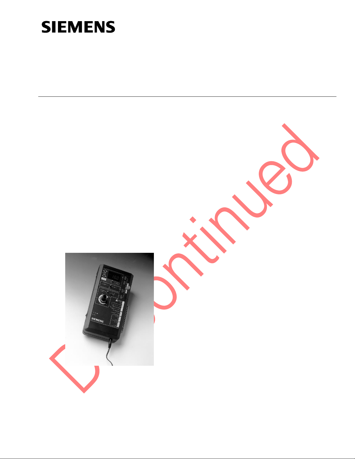
Product Description
The 985-047 Actuator Commissioning Tool provides
a portable instrument for exercising, calibrating, and
testing resistive, proportional (voltage/current),
floating, and on/off actuators. LED display shows
feedback voltages or output. LEDs indicate
operating mode selection and auxiliary switch
contact closure. The Commissioning Tool combines
accurate and reliable technology in a user-friendly,
yet economical package.
The Commissioning Tool saves on installation time
and is compatible with all Siemens actuators and
most competitors’ models. A plug-in transformer or
24 Vac power supply input enables the
Commissioning Tool to output resistance,
AC voltage, DC voltage, and current for controlling
an actuator. It requires no controller hook-up, which
makes equipment calibration, setup, and adjustment
a quick and easy process.
Figure 1. Actuator Commissioning Tool.
Features and Benefits
• Universal Compatibility
Works with all Siemens actuators, most
competitors’ actuators, and other voltage,
current, or resistance controlled equipment
• Compact Portable Unit
Allows easy handling in the field
• Pushbutton Selectable Output/Feedback
Modes
Gives user a complete testing device. No
separate instruments are required for field
testing
• Digital and LED feedback Displays
Provides user with clearly readable voltage
and auxiliary switch feedback in dimly lit
conditions
• Plug-in Terminal Block Test Lead
Connections
Accommodates easy interchangeability of
multiple sets of test leads
Contents
• Actuator Commissioning Tool
• Plug-in transformer
• Terminal blocks, set of three (extra)
• Carrying case
Required Tools
• Test leads
• 1/8 in. tip flat-blade screwdriver
Product Number
985-047
129-287
Operating Instructions
Rev. 1, October, 1999
Page 2 of 8 Siemens Industry, Inc.
Installation Conventions
WARNING
Personal injury/loss of life may
occur if a procedure is not
performed as specified.
CAUTION
Equipment damage, or loss of
data may occur if the user
does not follow procedure as
specified.
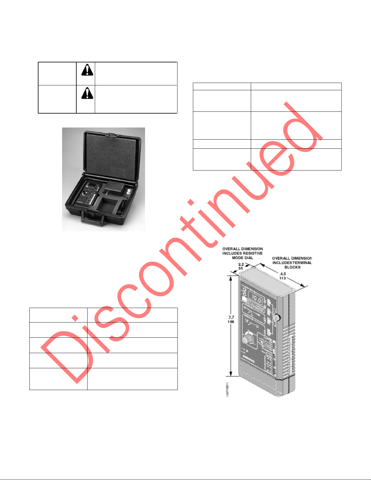
Figure 2. Actuator Commissioning Tool, Carrying
Case, Plug-in Transformer, and Three Extra Terminal
Blocks.
Application Overview
The Actuator Commissioning Tool has
four pushbutton selectable modes of operation as
follows:
Table 1. Output Control Signal Features.
Mode of
Operation
Description
Resistive *
0 to 135 ohms or 0 to 1k ohms for
use with resistive input actuators.
Voltage
0 to 20 Vdc for use with
proportional actuators
Current
0 to 20 mA for use with
proportional actuators
Floating Control
24 Vac (nominal) for use with
floating control and on/off
actuators
* The resistive mode is the default operating
mode when the commissioning tool is not
powered. To select other operating modes, the
ON/OFF switch must be turned ON. LEDs
indicate which mode is active.
The Commissioning Tool also provides additional
testing features as follows:
Table 2. Additional Testing Features.
Feature
Function
Power for Actuators
A 24 Vac (nominal) signal is
provided to power actuators that
are not externally powered.
Bias (for feedback
potentiometers)
A 5 Vdc bias signal is provided
through a 330 ohm resistor for
resistive feedback testing (for
feedback potentiometers).
Voltmeter
Measures 0 to 30 Vdc signal.
Switch Testing
LEDs display auxiliary contact
closure.
Use with dry contacts only!
The Commissioning Tool receives power by either:
• Applying 24 Vac (nominal) to the INPUTS
terminal block, or
• Connecting the 120V plug-in transformer
(provided) to its power jack.
Dimensions
Figure 3. Commissioning Tool Dimensions (in./mm).

129-287
Operating Instructions
Rev. 1, October, 1999
Siemens Industry, Inc. Page 3 of 8
Operation
WARNING:
Shock Hazard.
Disconnect all power supplies to the
Commissioning Tool and actuator or control
device before wiring to avoid possible
electrical shock or equipment damage.
Powering Commissioning Tool
CAUTION:
Equipment Damage Hazard.
Contact with water may result in damage to
the Commissioning Tool.
1. Apply 24 Vac (nominal) power from a remote
transformer or controller to Terminals 8 (COM)
and 9 (24 Vac) of the INPUTS terminal block on
the Commissioning Tool.
Or connect the plug-in 24 Vac transformer
(provided) to the power jack located on the
bottom of the Commissioning Tool (Figure 4).
Figure 4. Applying Power to the Commissioning Tool.
2. Turn the Commissioning Tool power switch,
located on the lower left side, to the ON
position. The green LED at the bottom left
corner of the Commissioning Tool lights,
indicating that the Commissioning Tool is
powered.
CAUTION:
Equipment Damage Hazard.
This device is only 24 Vac nominal. Applying
higher voltages could damage the device.
Powering a Non-externally Powered
Actuator or Control Device
CAUTION:
Equipment Damage Hazard.
Controlled equipment loading from Terminals 1
and 2 must be limited to 25 VA maximum.
NOTE: For 115-230 Vac actuators, the
Commissioning Tool can be used to
provide signal, but must be externally
powered.
1. To provide a 24 Vac (nominal) power signal,
connect Terminals 1 (24 Vac) and 2 (COM) of
the OUTPUTS terminal block on the
Commissioning Tool to the supply input
connections of the actuator or device being
powered (Figure 5).
NOTE: The output signal at Terminals 1 (24 Vac)
and 2 (COM) is equivalent to the input
signal that powers the Commissioning
Tool.
Figure 5. Connecting External Power to an Actuator
or Control Device.
Resistive Mode ()
CAUTION:
Equipment Damage Hazard.
Use the Commissioning Tool Resistive Mode
with only solid-state actuators and control
devices. Use with electromechanical devices
will cause damage to the Commissioning Tool.
The resistive mode can be used with or without
power supplied to the Commissioning Tool. When
power is not supplied to the Commissioning Tool,
the resistive mode is active. When power is initially
supplied to the Commissioning Tool, it defaults to
the resistive mode.
 Loading...