

Siemens 7SR10 Argus, 7SR1003 Argus, 7SR1002 Argus, 7SR1004 Argus Series Manual

7SR10 Argus
Overcurrent Relay
Reyrolle
Protection
Devices

Siemens Protecti on Devices Limit ed 2

Contents
Technical Manual Chapters
1. Description of Operation
2. Settings & Instruments Guide
3. Performance Specification
4. Data Communications
5. Installation
6. Commissioning and Maintenance
7SR10 Argus Contents
7. Applications Guide
The copyright and other intellectual property rights in this document, and in any model or article produced from it
(and including any registered or unregistered design rights) are the property of Siemens Protection Devices
Limited. No part of this document shall be reproduced or modified or stored in another form, in any data retrieval
system, without the permission of Siemens Protection Devices Limited, nor shall any model or article be
reproduced from this document unless Siemens Protection Devices Limited consent.
While the information and guidance given in this document is believed to be correct, no liability shall be accepted
for any loss or damage caused by any error or omission, whether such error or omission is the result of
negligence or any other cause. Any and all such liability is disclaimed.
© 2018 Siemens Protection Devices Limited

7SR10 Description of Operation
7SR10
Description of Operation
Document Release History
This document is issue 2018/07. The list of revisions up to and including this issue is:
2018/07
2018/06 Eleventh Issue
2017/09 Tenth Issue
2017/07
2017/04
2017/03
2016/11 Sixth Issue
2015/09 Fifth Issue
2015/06
2015/03
2015/02
2013/11 First Issue
Software Revision History (7SR1002/7SR1003)
2018/05 2437H80001 R4h-2d Operating system upgrade
2017/09 2437H80001 R4d-2c Data Communications improvements
2017/04 2437H80001 R4c-2b Minor modification in Analog
2016/11 2437H80001 R4b-2b Support for Reydisp manager tool
2015/09 2437H80001 R4b-2a Addition of AR variants
Twelfth Issue
Nineth Issue
Eighth Issue
Seventh Issue
Fourth Issue
Third Issue
Second Issue
2015/06 2437H80001 R4b-1f 81THD function added
2015/03 2437H80001 R4b-1e Addition of non-directional SEF device variants
2015/02 2437H80001 R4b-1d First Maintenance
2013/11 2436H80015 R2d-1a First Release
Software Revision History (7SR1004)
2018/06 2437H80008 R4h-1a First Release
The copyright and other intellectual property rights in this document, and in any model or article produced from it
(and including any registered or unregistered design rights) are the property of Siemens Protection Devices
Limited. No part of this document shall be reproduced or modified or stored in another form, in any data retrieval
system, without the permission of Siemens Protection Devices Limited, nor shall any model or article be
reproduced from this document unless Siemens Protection Devices Limited consent.
While the information and guidance given in this document is believed to be correct, no liability shall be accepted
for any loss or damage caused by any error or omission, whether such error or omission is the result of
negligence or any other cause. Any and all such liability is disclaimed.
©2018 Siemens Protection Devices Limited

7SR10 Description of Operation
Contents
Section 1: Introduction ....................................................................................................................................... 8
1.1 Current Transform er Circuits .............................................................................................................. 8
1.2 External Resistors.............................................................................................................................. 8
1.3 Description ........................................................................................................................................ 8
1.4 Ordering Options ............................................................................................................................... 9
1.5 Functional Diagram .......................................................................................................................... 11
1.6 Terminal Diagram ............................................................................................................................ 12
1.6.1 Terminal Diagram with Control Push Buttons ...................................................................... 12
Section 2: Hardware Description ...................................................................................................................... 14
2.1 General ........................................................................................................................................... 14
2.2 Front Fascia .................................................................................................................................... 15
2.2.1 Front Fascia with Control Push Buttons ............................................................................... 15
2.3 CB Open/Close ............................................................................................................................... 15
2.4 Power Supply Unit (PSU) ................................................................................................................. 16
2.5 Connectors ...................................................................................................................................... 17
2.5.1 Connectors with Control Push Buttons ................................................................................ 17
2.6 Relay Information ............................................................................................................................ 17
2.7 Operator Interface............................................................................................................................ 19
2.7.1 Liquid Crystal Display (LCD) ............................................................................................... 19
2.7.2 LCD Indication ................................................................................................................... 19
2.7.3 Standard Keys ................................................................................................................... 19
2.7.4 Protection Healthy LED ...................................................................................................... 20
2.7.5 Indication LEDs .................................................................................................................. 20
2.8 Current Inputs.................................................................................................................................. 20
2.9 Voltage Inputs ................................................................................................................................. 21
2.10 Binary Inputs ................................................................................................................................... 21
2.11 Binary Outputs (Output Relays) ........................................................................................................ 21
2.12 Virtual Input/Outputs ........................................................................................................................ 22
2.13 Self Monitoring ................................................................................................................................ 23
2.13.1 Protection Healthy/Defective ............................................................................................... 24
Section 3: Protection Functions ........................................................................................................................ 25
3.1 Current Protection: Phase Overcurrent (67, 51, 50) ........................................................................... 25
3.1.1 Directional Control of Overcurrent Protection (67) ................................................................ 25
3.1.2 Instantaneous Overcurrent Protection (50) .......................................................................... 26
3.1.3 Time Delayed Overcurrent Protection (51) .......................................................................... 27
3.1.4 Current Protection: Voltage Controlled Overcurrent (51V) .................................................... 29
3.2 Current Protection: Derived Earth Fault (67N, 51N, 50N)................................................................... 30
3.2.1 Directional Control of Derived Earth Fault Protection (67N) .................................................. 30
3.2.2 Instantaneous Derived Earth Fault Protection (50N) ............................................................ 31
3.2.3 Time Delayed Derived Earth Fault Protection (51N) ............................................................. 32
3.3 Current Protection: Measured Earth Fault (67G, 51G, 50G)............................................................... 34
3.3.1 Directional Control of Measured Earth Fault Protection (67G) .............................................. 34
3.3.2 Instantaneous Measured Earth Fault Protection (50G) ......................................................... 35
3.3.3 Time Delayed Measured Earth Fault Protection (51G) ......................................................... 36
3.4 Current Protection: Sensitive Earth Fault (67SEF, 51SEF, 50SEF) .................................................... 37
3.4.1 Directional Control of Sensitive Earth Fault Protection (67SEF) ............................................ 37
3.4.2 Instantaneous Sensitive Earth Fault Protection (50SEF) ...................................................... 38
3.4.3 Time Delayed Sensitive Earth Fault Protection (51SEF) ...................................................... 38
3.4.4 Current Protection: High Impedance Restricted Earth Fault - (64H) ...................................... 40
3.4.5 Current Protection: Cold Load (51c) .................................................................................... 40
3.4.6 Current Protection: Negative Phase Sequence Overcurrent - (46NPS) ................................. 41
3.4.7 Current Protection: Under-Current (37) ............................................................................... 42
3.4.8 Current Protection: Thermal Overload (49) .......................................................................... 43
3.4.9 Voltage Protection: Phase Under/Over Voltage (27/59) ....................................................... 44
3.4.10 Voltage Protection: Negative Phase Sequence Overvoltage (47NPS) .................................. 45
3.4.11 Voltage Protection: Neutral Overvoltage (59N) .................................................................... 46
3.4.12 Voltage Protection: Under/Over Frequency (81) .................................................................. 47
3.4.13 Power Protection: Power (32) ............................................................................................. 48
©2018 Siemens Protection Devices Limited Chapter 1 Page 2 of 77

7SR10 Description of Operation
3.4.14 Power Protection: Sensitive Power (32S) ............................................................................ 49
3.4.15 Power Protection: Power Factor (55) ................................................................................... 50
Section 4: Auto-Reclose (79) Optional Function ................................................................................................ 51
4.1.1 Overview............................................................................................................................ 51
4.1.2 Auto Reclose sequences .................................................................................................... 53
4.1.3 Autoreclose Prot’n Menu .................................................................................................... 54
4.1.4 Autoreclose Config Menu ................................................................................................... 54
4.1.5 P/F Shots sub-menu ........................................................................................................... 55
4.1.6 E/F Shots sub-menu ........................................................................................................... 55
4.1.7 SEF Shots sub-menu ......................................................................................................... 55
4.1.8 Extern Shots sub-menu ...................................................................................................... 55
4.2 Quick Logic ..................................................................................................................................... 58
4.3 Manual CB Control .......................................................................................................................... 59
4.4 Circuit Breaker (CB) ......................................................................................................................... 60
Section 5: Supervision Functions ...................................................................................................................... 62
5.1 Circuit Breaker Failure (50BF) .......................................................................................................... 62
5.2 2nd Harmonic Block/Inrush Restraint (81HBL2) Phase Elements Only .............................................. 63
5.3 Total Harmonic Distortion Supervision (81THD) ................................................................................ 63
5.4 VT Supervision (60VTS) .................................................................................................................. 64
5.5 CT Supervision (60CTS) .................................................................................................................. 65
5.5.1 60CTS-I ............................................................................................................................. 65
5.5.2 60CTS ............................................................................................................................... 66
5.6 Broken Conductor (46BC) ................................................................................................................ 66
5.7 Trip/ Close Circuit Supervision (74TCS & 74CCS) ............................................................................ 67
Section 6: Other Features ................................................................................................................................ 68
6.1 Data Communications ...................................................................................................................... 68
6.1.1 Communication Ports ......................................................................................................... 68
6.2 CB Maintenance .............................................................................................................................. 71
6.2.1 Output Matrix Test .............................................................................................................. 71
6.2.2 CB Counters ...................................................................................................................... 71
6.2.3 I2t CB Wear ........................................................................................................................ 72
6.3 Data Storage ................................................................................................................................... 72
6.3.1 General .............................................................................................................................. 72
6.3.2 Demand ............................................................................................................................. 72
6.3.3 Event Records ................................................................................................................... 72
6.3.4 Waveform Records............................................................................................................. 73
6.3.5 Fault Records..................................................................................................................... 73
6.3.6 Energy Storage .................................................................................................................. 73
6.3.7 Disk Activity W arning .......................................................................................................... 74
6.4 Metering .......................................................................................................................................... 75
6.5 Operating Mode ............................................................................................................................... 75
6.6 Control Mode ................................................................................................................................... 75
6.7 Real Time Clock .............................................................................................................................. 76
6.7.1 Time Synchronisation – Data Communication Interface ....................................................... 76
6.7.2 Time Synchronisation – Binary Input ................................................................................... 76
6.8 Settings Groups ............................................................................................................................... 76
6.9 Password Feature............................................................................................................................ 76
©2018 Siemens Protection Devices Limited Chapter 1 Page 3 of 77

7SR10 Description of Operation
List of Figures
Figure 2-1
Figure 2-2 7SR10 Non-Directional and Directional Overcurrent Relay with Connectors ....................................... 17
Figure 2-3 Relay Rating Label ........................................................................................................................... 18
Figure 2-4 Fascia Relay Rating Label ................................................................................................................ 18
Figure 2-5 Safety Symbols ................................................................................................................................ 18
Figure 2-6 Close up of Relay Identifier ............................................................................................................... 19
Figure 2-7 LED Indication Label ........................................................................................................................ 20
Figure 2-8 Binary Input Logic ............................................................................................................................. 21
Figure 2-9 Binary Output Logic .......................................................................................................................... 22
Figure 2-10 Start-up Counter Meter ..................................................................................................................... 23
Figure 2-11 Unexpected Restarts Lockout Text .................................................................................................... 23
Figure 2-12 Start-up Events ................................................................................................................................ 24
Figure 3-1 Logic Diagram: Directional Overcurrent Element (67)......................................................................... 26
Figure 3-2 Logic Diagram: Instantaneous Over-current Element ......................................................................... 27
Figure 3-3 Logic Diagram: Time Delayed Overcurrent Element ........................................................................... 28
Figure 3-4 Logic Diagram: Voltage Controlled Overcurrent Protection ................................................................. 29
Figure 3-5 Logic Diagram: Derived Directional Earth Fault Element .................................................................... 30
Figure 3-6 Logic Diagram: Derived Instantaneous Earth Fault Element ............................................................... 31
Figure 3-7 Logic Diagram: Derived Tim e Delayed Earth Fault Protection ............................................................ 33
Figure 3-8 Logic Diagram: Measured Directional Earth Fault Protection .............................................................. 34
Figure 3-9 Logic Diagram: Measured Instantaneous Earth-fault Element ............................................................ 35
Figure 3-10 Logic Diagram: Measured Time Delayed Earth Fault Element (51G) .................................................. 36
Figure 3-11 Logic Diagram: SEF Directional Element (67SEF) ............................................................................. 37
Figure 3-12 Logic Diagram: 7SR10 SEF Instantaneous Element .......................................................................... 38
Figure 3-13 Logic Diagram: 7SR10 SEF Instantaneous Element .......................................................................... 38
Figure 3-14 Logic Diagram: 7SR10 SEF Time Delayed Element (51SEF) ............................................................. 39
Figure 3-15 Logic Diagram: 7SR10 SEF Time Delayed Element (51SEF) ............................................................. 39
Figure 3-16 Logic Diagram: High Impedance REF (64H) ...................................................................................... 40
Figure 3-17 Logic Diagram: Cold Load Settings (51c)........................................................................................... 41
Figure 3-18 Logic Diagram: Negative Phase Sequence Overcurrent (46NPS) ....................................................... 42
Figure 3-19 Logic Diagram: Phase Current Inputs Undercurrent Detector (37) ...................................................... 42
Figure 3-20 Logic Diagram: Earth Current Inputs Undercurrent Detector (37G) ..................................................... 43
Figure 3-21 Logic Diagram: Sensitive Earth Current Inputs Undercurrent Detector (37SEF) .................................. 43
Figure 3-22 Logic Diagram: Thermal Overload Protection (49) ............................................................................. 44
Figure 3-23 Logic Diagram: Under/Over Voltage Elements (27/59) ....................................................................... 45
Figure 3-24 Logic Diagram: NPS Overvoltage Protection (47) .............................................................................. 45
Figure 3-25 Logic Diagram: Neutral Overvoltage Element (59N) ........................................................................... 46
Figure 3-26 Logic Diagram: Under/Over Frequency Detector (81)......................................................................... 47
Figure 3-27 Logic Diagram: Power Protection (32) ............................................................................................... 48
Figure 3-28 Logic Diagram: Sensitive Power Protection (32S) .............................................................................. 49
Figure 3-29 Logic Diagram: Power Factor Protection (55) .................................................................................... 50
Figure 4-1 Typical AR Sequence with 3 Inst and 1 Delayed trip .......................................................................... 53
Figure 4-2 Basic Auto-Reclose Sequence Diagram ............................................................................................ 57
Figure 4-3 Sequence Diagram: Quick Logic PU/DO Timers (Counter Reset Mode Off) ........................................ 58
Figure 4-4 Logic Diagram: Circuit Breaker Status ............................................................................................... 61
Figure 5-1 Logic Diagram: Circuit Breaker Fail Protection (50BF) ....................................................................... 62
Figure 5-2 Logic Diagram: Harmonic Block Feature (81HBL2) ............................................................................ 63
Figure 5-3 Logic Diagram: Total Harmonic Distortion Supervision Element (81THD) ........................................... 64
Figure 5-4 Logic Diagram: VT Supervision Function (60VTS) ............................................................................. 65
Figure 5-5 Logic Diagram: CT Supervision Function (60CTS) ............................................................................. 66
7SR10 Argus Overcurrent Relay with Control Push Buttons ............................................................... 15
©2018 Siemens Protection Devices Limited Chapter 1 Page 4 of 77

7SR10 Description of Operation
Figure 5-6 Logic Diagram: CT Supervision Function (60CTS) ............................................................................. 66
Figure 5-7 Logic Diagram: Broken Conductor Function (46BC) ........................................................................... 67
Figure 5-8 Logic Diagram: Trip Circuit Supervision Feature (74TCS) .................................................................. 67
Figure 5-9 Logic Diagram: Close Circuit Supervision Feature (74CCS) ............................................................... 67
Figure 6-1 Communication to Front USB Port .................................................................................................... 68
Figure 6-2 Connect Icon .................................................................................................................................... 68
Figure 6-3 Port Selection in Connection Manager .............................................................................................. 69
Figure 6-4 System Information Icon ................................................................................................................... 69
Figure 6-5 System Inform ation Icon ................................................................................................................... 70
Figure 6-6 Communication to Multiple Devices from Control System using RS485 .............................................. 71
Figure 6-7 Energy Direction Convention............................................................................................................. 74
©2018 Siemens Protection Devices Limited Chapter 1 Page 5 of 77

7SR10 Description of Operation
List of Tables
Table 2-1
Table 6-1 Operation Mode ............................................................................................................................... 75
Summary of 7SR10 Argus Overcurrent Relay Configurations ............................................................. 14
©2018 Siemens Protection Devices Limited Chapter 1 Page 6 of 77

7SR10 Description of Operation
Symbols and Nomenclature
The following notational and formatting conventions are used within the remainder of this document:
• Setting Menu Location MAIN MENU>SUB-MENU
• Setting: Elem name -Setting
• Setting value: value
• Alternatives: [1st] [2nd] [3rd]
©2018 Siemens Protection Devices Limited Chapter 1 Page 7 of 77

7SR10 Description of Operation
!
!
Section 1: Introduction
This manual is applicable to the following relay:
• 7SR10 Overcurrent Relay
General Safety Precautions
1.1 Current Transformer Circuits
The secondary circuit of a live CT must not be open circuited. Non-observance of this precaution can
result in injury to personnel or damage to equipment.
1.2 External Resistors
Where external resistors are connected to the relay circuitry, these may present a danger of electric
shock or burns, if touched.
1.3 Description
The 7SR10 Overcurrent relay is developed by using the latest generation of hardware technology and is available
in multiple variants depending on power supply, binary input/output
communication facility. 7SR10 is a member of Siemens Reyrolle
The 7SR10 overcurrent relay consists of non directional functions and with additional voltage inputs providing
directional functions (based on the ordering option).
The 7SR10 Overcurrent relay is housed in a 4U high, size 4 non draw-out case and these relays provide
protection, monitoring, instrumentation, and metering with integrated input and output logic, data logging and fault
reports.
Communication access to the relay functionality is via a front USB port for local PC connection or rear electrical
RS485 (optional) port for remote connection.
configuration, voltage input, and data
®
protection devices Argus product family.
©2018 Siemens Protection Devices Limited Chapter 1 Page 8 of 77

7SR10 Description of Operation
Product Description
Variants
Order No.
1 2 3 4 5 6 7 - 8 9 10
11
12 - 13
14
15
16
7SR10 Argus
7 S R 1 0 0 - 0 - A 0
Non-Directional O/C Relay (Argus)
Case, I/O and Fascia
Size 4 Moulded case, 4 CT, 3 Binary Inputs/3 Binary Outputs, 10
LEDs
2 1 1
Size 4 Moulded case, 4CT, 6 Binary Inputs/6 Binary Outputs, 10 LEDs
3
Measuring input
1/5 A, 50/60Hz 1)
2/3 1
1/5 A, 50/60Hz with SEF input 2)
3 2
Auxiliary voltage
AC/DC 60-240V, Binary input threshold 44 V AC/DC
L
AC/DC 60-240V, Binary input threshold 88 V AC/DC
K
DC 24-60 V, Binary input threshold 19 VDC
J
Protective Cover
Standard version – No Cover
Plastic Cover with 1 Push Button for Test/Reset
A B
Communication
Front Port : USB
2
1
Front Port : USB and Rear Port : RS-485 supporting IEC 60870-5-103
or Modbus RTU or DNP 3.0
3 2
Front Fascia
Standard Version – with Breaker Control Push Buttons
2
Protection Function Packages
C
Standard version - included in all models
46BC
Broken conductor/Load unbalance
46NPS
Negative phase sequence overcurrent
49
Thermal overload
50
Instantaneous phase fault overcurrent
50BF
Circuit breaker fail
50G/N
Instantaneous earth fault
50SEF
2)4)
Instantaneous sensitive earth fault overcurrent
51
Timed delayed phase fault overcurrent
51 G/N
Timed delayed earth fault
51SEF
2)4)
Time delayed sensitive earth fault
74T/CCS
Trip/close circuit supervision
81HBL2 3)
2nd Harmonic block/Inrush restraint
86
Hand reset contacts
51C
Cold load pickup
Programmable logic
81THD
Total harmonic distortion supervision
Standard version – plus
79 Autoreclose
D Additional Functionality
No Additional Functionality
A
Z Y 2 0
1.4 Ordering Options
Special version
1)
4CT is configured as 3PF + EF
2)
4CT is configured as 3PF + SEF
3)
Not available on SEF input
4)
Only with position 7 = 3
5)
Special version for Turkey market with thermal withstand capability of 500A (5A CT), 1 sec and
5)
supporting Turkish scripts.
Available only with position 8 = 1
©2018 Siemens Protection Devices Limited Chapter 1 Page 9 of 77

7SR10 Description of Operation
Product Description
Variants
Order No.
1 2 3 4 5 6 7 - 8 9 10
11
12 - 13
14
15
16
7SR10 Argus
7 S R 1 0 0 - 0 - A 0
Directional Overcurrent Relay (Argus)
Case, I/O and Fascia
Size 4 Moulded case, 4CT, 3 VT, 9 Binary Inputs/6 Binary Outputs,
10 LEDs
4
Measuring input
1A/5A, 50Hz/60Hz, 63.5/110V 1)
3
1A/5A, 50Hz/60Hz with SEF input, 63.5/110V 2)
4
Auxiliary voltage
AC/DC 60-240V, Binary input threshold 44V AC/DC
L
AC/DC 60-240V, Binary input threshold 88V AC/DC
K
DC 24-60V, Binary input threshold 19V DC
J
Protective Cover
Standard version – No Cover
Plastic Cover with 1 Push Button for Test/Reset
A B
Communication
Front Port : USB and Rear Port : RS-485 supporting IEC 60870-5-103
or Modbus RTU or DNP 3.0
2
Front Fascia
Standard Version – with Breaker Control Push Buttons
2
Protection Function Packages
C
Standard version - included in all models
27/59
Under/overvoltage
32
Power
32S
Sensitive Power
37
Undercurrent
37G1)
Undercurrent measured earth fault
37SEF2)
46BC
Broken conductor/Load Unbalance
46NPS
Negative phase sequence overcurrent
47NPS
Negative phase sequence ov ervoltage
49
Thermal overload
50BF
Circuit breaker fail
51V
Voltage dependent overcurrent
55
Power Factor
59N
Neutral voltage displacement
60CTS
CT supervision
60VTS
VT supervision
64H
High impedance REF
67/50
Directional instantaneous phase fault overcurrent
67/50G1) 67/50N
Directional instantaneous earth fault
67/50SEF 2)
67/51
Directional time delayed phase fault overcurrent
67/51G1) 67/51N
67/51SEF 2)
Directional time delayed sensitive earth fault
81HBL2 3)
74T/CC
Trip & close circuit supervision
51C
Cold load pickup/Programmable Logic
81U/O
Under/Over Frequency
86
Hand reset contacts
Standard version – plus
79 Autoreclose
D
Additional Functionality
No Additional Functionality
A
Undercurrent sensitive earth fault
Instantaneous sensitive earth fault
Directional time delayed earth fault
2nd Harmonic block/Inrush restraint
1)
4CT is configured as 3PF + EF
2)
4CT is configured as 3PF + SEF
3)
Not available on SEF input
©2018 Siemens Protection Devices Limited Chapter 1 Page 10 of 77

7SR10 Description of Operation
7
SR10
49
50
(x2)51(x2)
50G
(x2)
51G
(x2)
50
BF
50N
(x2)
51N
(x2)
46
BC
46
NPS
(x
2
)
81
HBL2
49
50
(x2)
50
BF
81
HBL
2
49
50
(x2)
50
BF
81
HBL2
74
T/CCS
51
(
x2
)
51
(x2)
81
HBL2
N
81
HBL2
G
I
L1
(I
A
)
I
L
2
(IB)
I
L3
(I
C
)
50
BF
51c
51c
51c
86
I
4
(I
G
)
51SEF
(x2)
50SEF
(x2)
81
THD
81
THD
81
THD
79
Optional Version D software
Fig 1. 7SR10 Overcurrent Relay (Non-Directional)
7SR10
64H
46
BC
46
NPS
(x2)
37
(x2)
49
50
BF
V1
V2
V3
37
(x2)
49
50
BF
37
(x2)
49
50
BF
60
CTS
74
T/CCS
67/
50
(x4)
67/
51
(x4)
67/
50N
(x4)
67/
50
(x4)
67/
50
(x4)
67/
51
(x4)
67/
51
(x4)
67/
51N
(x4)
67/
50G
(x4)
67/
51G
(x4)
27
59
(x4)
27
59
(x4)
27
59
(x4)
59N
(x2)
47
(x2)
50
BF
50
BF
37 SEF
(x2)
81
HBL 2
81
HBL 2
81
HBL 2
51V
51V
51V
67/
50SEF
(x4)
67/
51SEF
(x4)
81
(x4)
86
I
L1
(IA)
I
L2
(IB)
I
L3
(IC)
I
4
(I
G/
SEF
)
32S
(x2)
60
VTS
51c
51c
51c
32
(x2)
32
(x2)
32
(x2)
55
(x2)
55
(x2)
55
(x2)
81
HBL 2
G
37G
(x2)
79
Optional Version D software
Fig 2. 7SR10 Overcurrrent Relay (Directional)
1.5 Functional Diagram
©2018 Siemens Protection Devices Limited Chapter 1 Page 11 of 77
7SR10 Description of Operation
BI 1
Term.
RS485
A
GND
B
+ve
-ve
1
2
3
1
2
BI 2
+ve
-ve
3
4
BI 3
+ve
-ve
5
6
1
2
3
4
BI 4
+ve
-ve
7
8
BI 5
+ve
-ve
9
10
BI 6
+ve
-ve
11
12
X2
X3
X4
X5
BO3
7
8
BO5
11
12
BO6
13
14
IL4
5A
10
11
12
1A
IL3
5A
7
8
9
1A
IL2
5A
4
5
6
1A
IL1
5A
1
2
3
1A
5
6
4
BO 2
BO 1
2
3
1
BO4
9
10
X1
GND
L
N
E
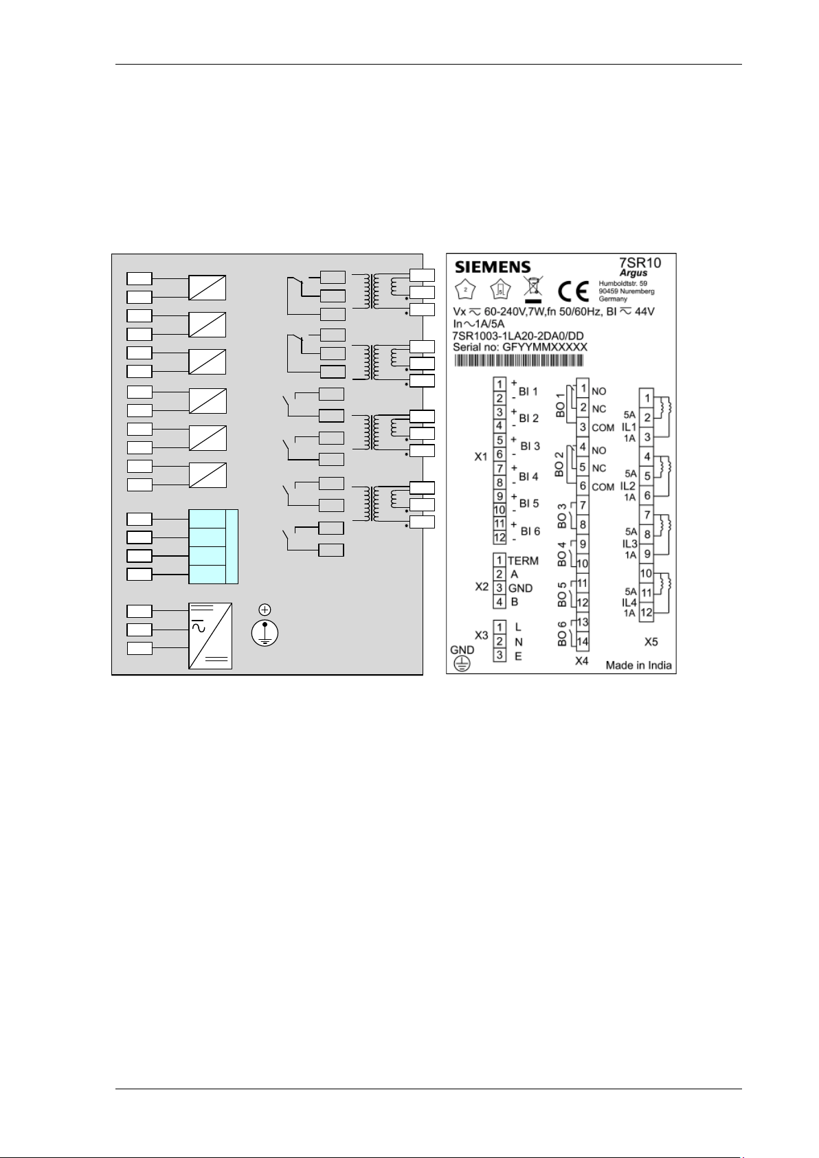
Fig 3. Terminal/Wiring Diagram of 7SR10 Non-Directional Overcurrent Relay
1.6 Terminal Diagram
The relay is housed in a non draw-out case 4U high Size 4 case. The rear connection comprises of user friendly
pluggable type terminals for the Voltage Inputs, Binary Inputs, Binary Outputs, Communication, and Power
Supply.
The CT terminals are fixed type and suitable for ring type lug connection to provide a secure and reliable
termination.
1.6.1 Terminal Diagram with Control Push Buttons
NOTE:
For DC variants, connect the positive and negative terminals to X3: L and X3: N terminals respectively.
©2018 Siemens Protection Devices Limited Chapter 1 Page 12 of 77
7SR10 Description of Operation
BI 1
Term
RS485
A
GND
B
+ve
-ve
1
2
3
1
2
BI 2
+ve
-ve
3
4
BI 3
+ve
-ve
5
6
1
2
3
4
BI 4
+ve
-ve
7
8
BI 5
+ve
-ve
9
10
BI 6
+ve
-ve
11
12
X2
X3
X4
X5
BO3
7
8
BO5
11
12
BO6
13
14
IL4
5A
10
11
12
1A
IL3
5A
7
8
9
1A
IL2
5A
4
5
6
1A
IL1
5A
1
2
3
1A
5
6
4
BO 2
BO 1
2
3
1
BO4
9
10
X1
BI 7
+ve
-ve
1
2
BI 8
+ve
-ve
3
4
BI 9
+ve
-ve
5
6
X6
V1
1
2
V2
3
4
V3
5
6
X7
GND
L
N
E
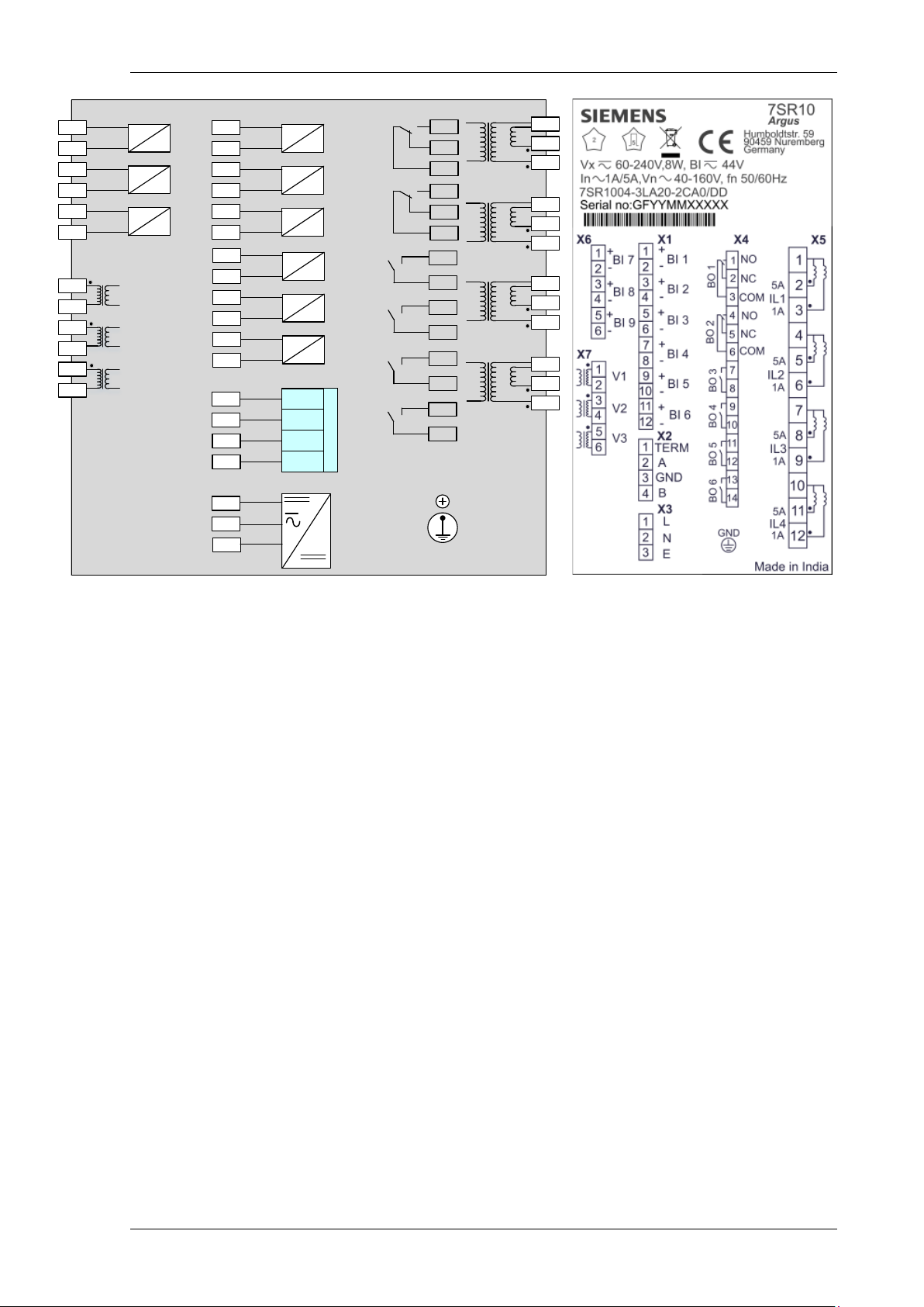
Fig 4. Terminal/Wiring Diagram of 7SR10 Directional Overcurrent Relay
NOTE:
For DC variants, connect the positive and negative terminals to X3: L and X3: N terminals respectively.
©2018 Siemens Protection Devices Limited Chapter 1 Page 13 of 77
7SR10 Description of Operation
Section 2: Hardware Description
2.1 General
The structure of the relay is based upon the compact hardware platform. The relays are supplied in a Size 4 case.
The hardware design provides a commonality between the products and components across the range of relays.
Table 2-1 Summary of 7SR10 Argus Overcurrent Relay Configurations
Relay Current
Inputs
7SR1002 4 0 3 3 10
7SR1003 4 0 6 6 10
7SR1004 4 3 9 6 10
The 7SR10 Argus Overcurrent Relay is assembled from the following modules:
1. Front Fascia with 9 configurable LEDs and 1 Relay Healthy LED
2. Processor module
3. Current Analogue, Voltage Analogue, Input module and Output module
With control push buttons
4 x Current (Terminal X5)
6 x Binary Input (Terminal X1)
6 x Binary Outputs (Terminal X4)
3 x Voltage Inputs (Terminal X7)
Voltage
Inputs
Binary
Inputs
Binary
Outputs
LEDs
3 x Binary Input (Terminal X6)
4. Communication and Power Supply module
With control push buttons
RS485 (Terminal X2)
Power supply (Terminal X3)
©2018 Siemens Protection Devices Limited Chapter 1 Page 14 of 77
7SR10 Description of Operation
Button
Function
Description
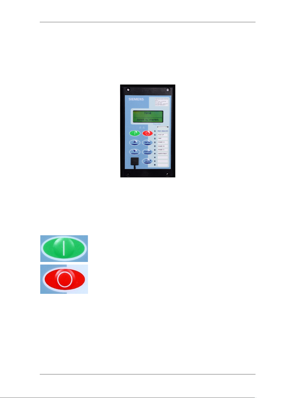
2.2 Front Fascia
The front fascia is an integral part of the relay and allows the user to access all the push buttons and performs the
setting changes and control actions. The fascia provides an option to reset the fault data display, latched binary
outputs, and LEDs by using the TEST/RESET► button. The front fascia contains the label strip which provides
the information about LED indicators.
Front Fascia consists of CB control push buttons to open and close.
2.2.1 Front Fascia with Control Push Buttons
Figure 2-1 7SR10 Argus Overcurrent Relay with Control Push Buttons
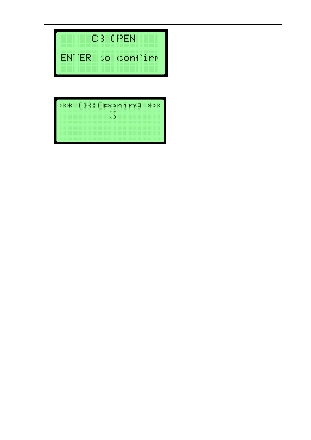
2.3 CB Open/Close
The circuit breaker (CB) control function is used to manually open and close the CB when it is connected to the
network. Two dedicated push buttons are provided on the HMI to execute the CB manual close and open
operations.
Close Press Close button and confirm ENTER to execute the close
operation of circuit breaker.
Open Press Open button and confirm ENTER to execute the open
operation of circuit breaker.
The user can configure the binary input, binary output, and LED configuration for the CB open and close control
functions.
To perform the CB open and close control operations, follow the procedure given below:
1. Apply CB Close Binary Input (BI) to get the breaker status.
2. Press CB OPEN control key. The confirmation pop-up appears.
©2018 Siemens Protection Devices Limited Chapter 1 Page 15 of 77
7SR10 Description of Operation
3. Press ENTER key to confirm.
4. The CB Open delay count-down starts and reaches to zero.
5. The configured BO and LED’s for the CB OPEN control functions will operate.
6. Press RESET button to reset LED and BO states.
Repeat the same procedure for CB CLOSE control logic operation.
NOTE:
If the "Control Password" is already configured in the settings, use the control password to execute the CB
open/close via control keys. For more information about the Control Password function, see
NOTE:
If the operating mode of 7SR10 Relay is remote, the user can perform the CB open and close operations when
the “FUNCTION KEY CONFIG” setting is enabled.
Section 6.9
2.4 Power Supply Unit (PSU)
The relay is supplied with the following nominal power supply ranges:
• 60 V - 240 V AC/DC power supply (BI threshold - 88 V AC/DC or 44 V AC/DC)
• 24 V - 60 V DC power supply (BI threshold - 19 V DC)
The power supply module is equipped with 3 or 6 Binary Inputs. It also consists of one RS485 communication
interface (half duplex) for communicating with RTUs and parameterization of relays via remote locations.
For AC connections, the auxiliary supply is made with the live connection to positive terminal and neutral
connection to negative for consistency and safety.
For DC connections, the auxiliary supply is made with the positive connection to Line terminal (L) and negative
connection to Neutral (N) for consistency and safety.
In the event of the supply voltage levels are falling below the relay minimum operate level, the PSU will
automatically switch off itself and latch out and this prevents any PSU overload conditions occurring. The PSU is
reset by switching the auxiliary supply off and on.
©2018 Siemens Protection Devices Limited Chapter 1 Page 16 of 77
7SR10 Description of Operation
Current
Inputs
Binary
Output
Binary
Input
Rear
Communic ation
Port
Auxili ary
Supply
Current
Inputs
Binary
Output
Auxili ary
Supply
Rear
Communic ation
Port
Voltage
Inputs
Binary
Input
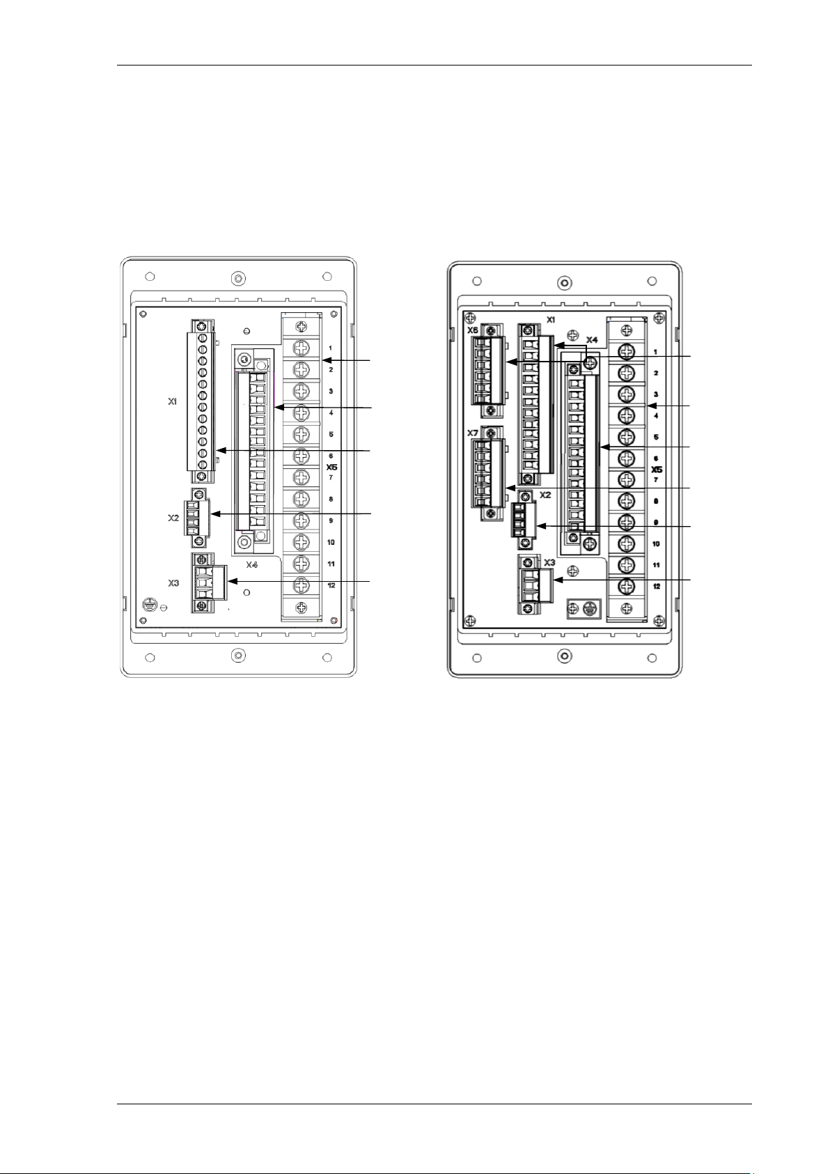
Figure 2-2 7SR10 Non-Directional and Directional Overcurrent Relay with Connectors
2.5 Connectors
In 7SR10 Argus Overcurrent relay, all the connectors are pluggable type except the CT connectors and it consists
of Binary Inputs and Binary Outputs connectors. The connector terminals are designated suitably.
In 7SR10 Argus Overcurrent relay, the CT connectors are fixed type. The other connectors for Voltage Inputs,
Binary Inputs, Binary Outputs, Communication, and Power Supply are pluggable type and designated suitably.
2.5.1 Connectors with Control Push Buttons
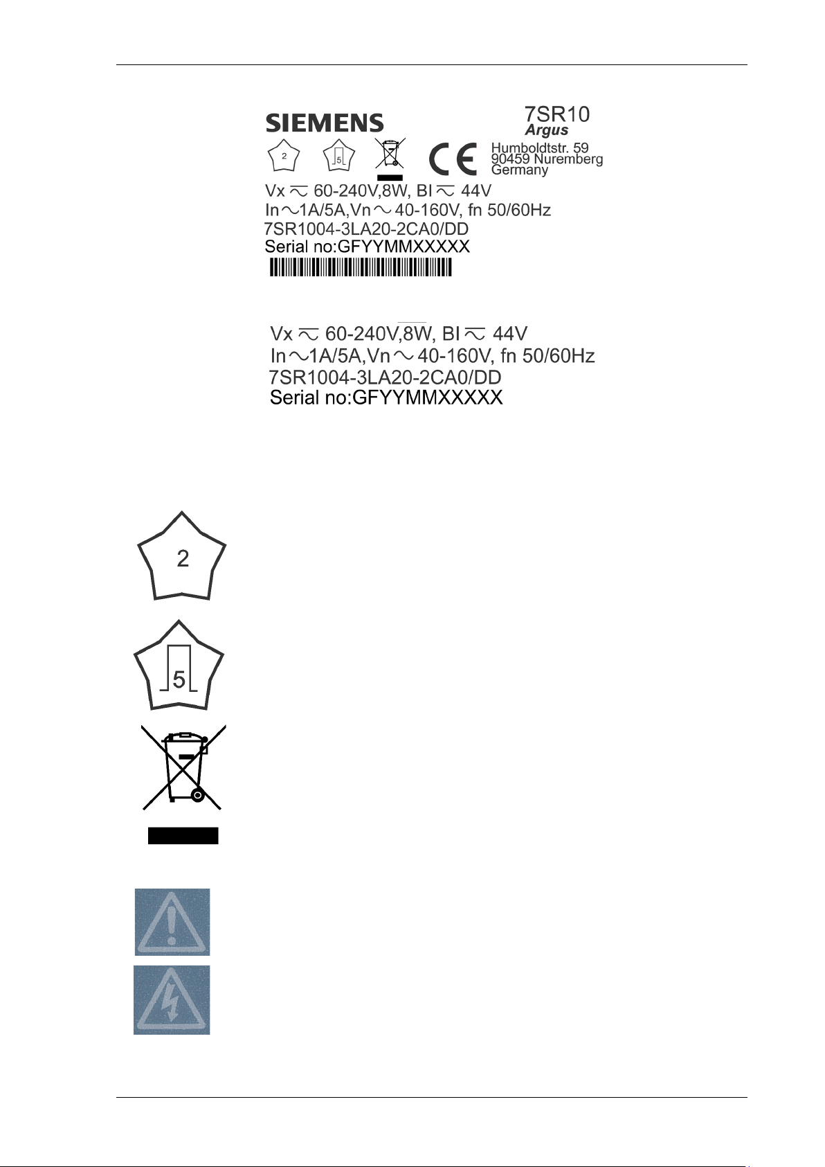
2.6 Relay Information
The rating label is located on the housing and provides more technical information about 7SR10 Argus
Overcurrent relay.
Relay Information
The rating label contains the following product Information:
• Product name
• MLFB ordering code, with hardware version suffix
• Nominal current rating
• Nominal voltage rating
• Rated frequency
• Auxiliary supply rating
• Binary input supply rating
• Seri al number
©2018 Siemens Protection Devices Limited Chapter 1 Page 17 of 77
7SR10 Description of Operation
For safety reasons, the following symbols are displayed on the 7SR10 Argus Overcurrent relay.
product should not be disposed with other wastes at the end of its working
responsibly to promote the sustainable reuse of material resources. This will
Caution: Risk of Electric Shock
Caution: Refer to Equipment Documentation
Safety Symbols
Figure 2-3 Relay Rating Label
Figure 2-4 Fascia Relay Rating Label
Dielectric test voltage 2kV
Impulse voltage withstand 5kV
“WEEE" Symbol instructions.
The
life. Please separate the product from other types of wastes and recycle it
help prevent harm to the environment or human health from uncontrolled waste
disposal.
For safety reasons the following symbols are displayed on the fascia.
©2018 Siemens Protection Devices Limited Chapter 1 Page 18 of 77
Figure 2-5 Safety Symbols
7SR10 Description of Operation
2.7 Operator Interface
2.7.1 Liquid Crystal Display (LCD)
A 4 line by 20-character alpha-numeric liquid crystal display indicates settings, instrumentation, fault data, and
control commands.
To conserve power, the display backlighting is extinguished when no buttons are pressed for a user-defined
period. The ‘backlight timer’ setting within the “SYSTEM CONFIG” menu allows the timeout to be adjusted from 1
to 60 minutes and “Off” (backlight permanently on). Pressing any key will reactivate the display.
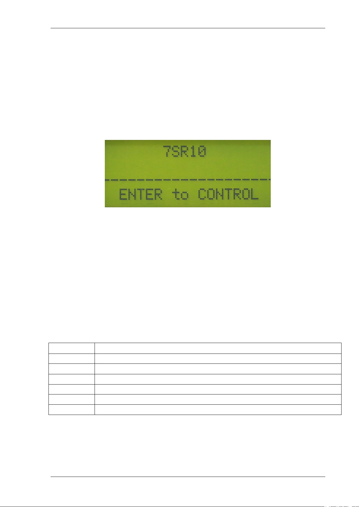
User-defined identifying text can be programmed into the relay by using the System config/Relay Identifier and
System config/Circuit Identifier setting. The ‘Identifier’ texts are displayed on the LCD display in two lines at the
top level of the menu structure. The ‘Relay Identifier’ is used in communication with Reydisp to identify the relay.
By pressing the Cancel button several times will return the user to this screen.
Figure 2-6 Close up of Relay Identifier
2.7.2 LCD Indication
General Alarms are user defined text messages displayed on the LCD when mapped to binary inputs or virtual
inputs. Up to six general alarms of 16 characters can be programm ed, each triggered from one or more input.
Each general alarm will also generate an event.
If multiple alarms are activated simultaneously, the messages are displayed on a separate page in a
rolling display on the LCD. The System Config > General Alarm Alert setting Enabled/Disabled allows the user
to select if the alarms are to be displayed on the LCD when active.
All general alarms are raised when a fault trigger is generated and will be logged into the Fault Data record.
2.7.3 Standard Keys
The relay is supplied as standard with seven push buttons. The buttons are used to navigate the menu structure
and control the relay functions. They are labelled:
▲
▼ Decreases a setting or moves down menu.
TEST/RESET► Moves right, can be used to reset selected functionality and for LED test (at relay identifier screen).
ENTER Used to initiate and accept settings changes.
CANCEL Used to cancel settings changes and/or move up the menu structure by one level per press.
OPEN Used to execute the open of circuit breaker
Increases a setting or moves up menu.
CLOSE Used to execute the close of circuit breaker
NOTE:
All settings and configuration of LEDs, BI and BO can be accessed and set by the user using these keys.
Alternatively, the configuration/settings files can be loaded into the relay using ‘Reydisp’ software. When the
System Config > Setting Dependencies is ENABLED, only the functions that are enabled will appear in the
menu structure.
©2018 Siemens Protection Devices Limited Chapter 1 Page 19 of 77
7SR10 Description of Operation
2.7.4 Protection Healthy LED
This green LED is steadily illuminated to indicate that auxiliary voltage has been applied to the relay power supply
and that the relay is operating correctly. If the internal relay watchdog detects an internal fault then the LED will
continuously flash.
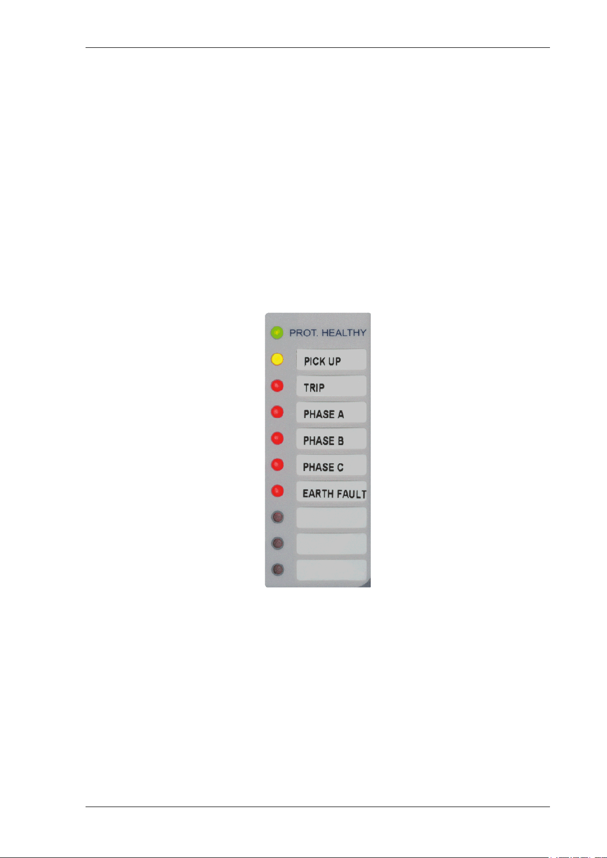
2.7.5 Indication LEDs
Relays have 9 user programmable LED indicators. Each LED can be programmed to be illuminated as either
green, yellow, or red. Where an LED is programmed to be lit both red and green, it will illuminate yellow. The
same LED can be assigned two different colours dependent upon whether a Start/Pickup or Operate condition
exists. LED’s can be assigned to the pickup condition and colour selected in the OUTPUT CONFIG > LED
CONFIG menu.
Functions are assigned to the LEDs in the OUTPUT CONFIG > OUTPUT MATRIX menu.
Each LED can be labelled by inserting a label strip into the pocket behind the front fascia. A ‘template’ is available
in the Reydisp software tool to allow users to create and print customised legends.
Each LED can be programmed as hand reset or self reset. Hand reset LEDs can be reset either by pressing the
TEST/RESET ► button, energising a suitably programmed binary input or by sending an appropriate command
over the data communications channel(s).
The status of hand reset LEDs is maintained by a back up storage capacitor in the event of an interruption to the
supply voltage.
Figure 2-7 LED Indication Label
2.8 Current Inputs
Four current inputs are provided on the Analogue Input module. Terminals are available for both 1 A and 5 A
inputs.
The current input is incorporated within the relay and is used for phase fault and earth fault protection.
Current is sampled at 1600 Hz for both 50 Hz and 60 Hz system frequencies. Protection and monitoring functions
of the relay use either the Fundamental Frequency RMS or the True RMS value of current appropriate to the
individual function.
The waveform recorder samples and displays current input waveforms at 1600 Hz.
The primary CT ratio used for the relay instruments can be set in the CT/VT configuration menu.
©2018 Siemens Protection Devices Limited Chapter 1 Page 20 of 77
7SR10 Description of Operation
Event
BI 1
Binary Input 1
=1
Inverted Inputs
BI 1 inverted
BI 1 P/U Delay
Event
BI n
Binary Input n
=1
BI n inverted
BI n P/U Delay
INPUT CONFIG>
INPUT MATRIX
(Or gates)
Logic signals,
e.g. '51-1 Inhibit'
BI 1 D/O Delay
BI n D/O Delay
INPUT
CONFIG>
BINARY
INPUT
CONFIG
2.9 Voltage Inputs
Three voltage inputs are provided on the Analogue Input module on the 7SR10 relay.
Voltage is sampled at 1600Hz for both 50Hz and 60Hz system frequencies. Protection and monitoring functions of
the relay use fundam ental frequency voltage measurement.
The waveform recorder samples and displays voltage input waveforms at 1600Hz.
The primary VT ratio used for the relay instruments can be set in the CT/VT configuration menu.
2.10 Binary Inputs
The binary inputs are opto-couplers operated from a suitably rated power supply.
Relays are fitted with 3 or 6 or 9 binary inputs (BI) depending on the variant. The user can assign any binary input
to any of the available functions (INPUT CONFIG > INPUT MATRIX).
Pick-up (PU) and Drop-off (DO) time delays are associated with each binary input. Where no pick-up tim e delay
has been applied the input may pick up due to induced AC voltage on the wiring connections (e.g. cross site
wiring). The default pick-up time of 20 ms provides AC immunity. Each input can be programmed independently.
Each input may be logically inverted to facilitate integration of the relay within the user scheme. When inverted the
relay indicates that the BI is energised when no voltage is applied. Inversion occurs before the PU and DO time
delay.
Each input may be mapped to any front Fascia indication LED and/or to any Binary output contact and can also
be used with the internal user programmable logic. This allows the relay to provide panel indications and alarms.
Each binary input is set by default to be read when the relay is in both the local or remote condition. A setting is
provided to allow the user to select if each individual input shall be read when the relay is in the local or remote
condition in the INPUT CONFIG > BINARY INPUT CONFIG menu.
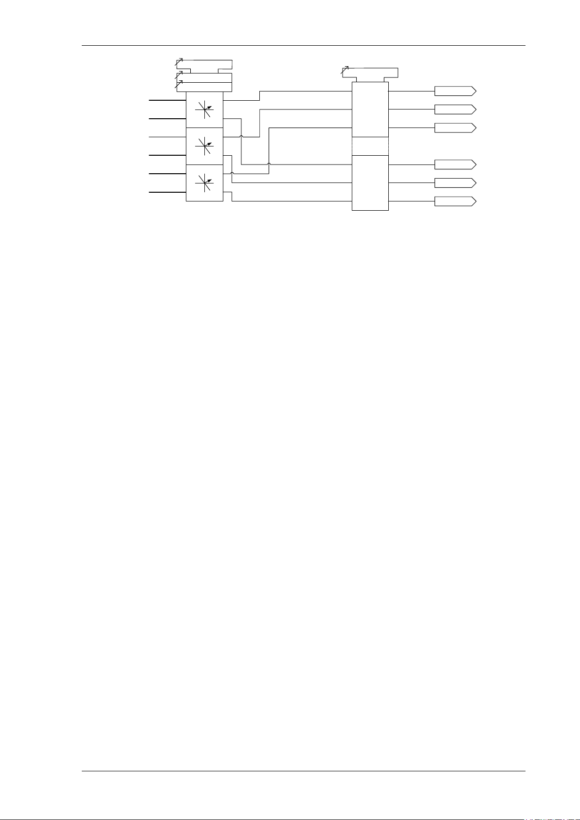
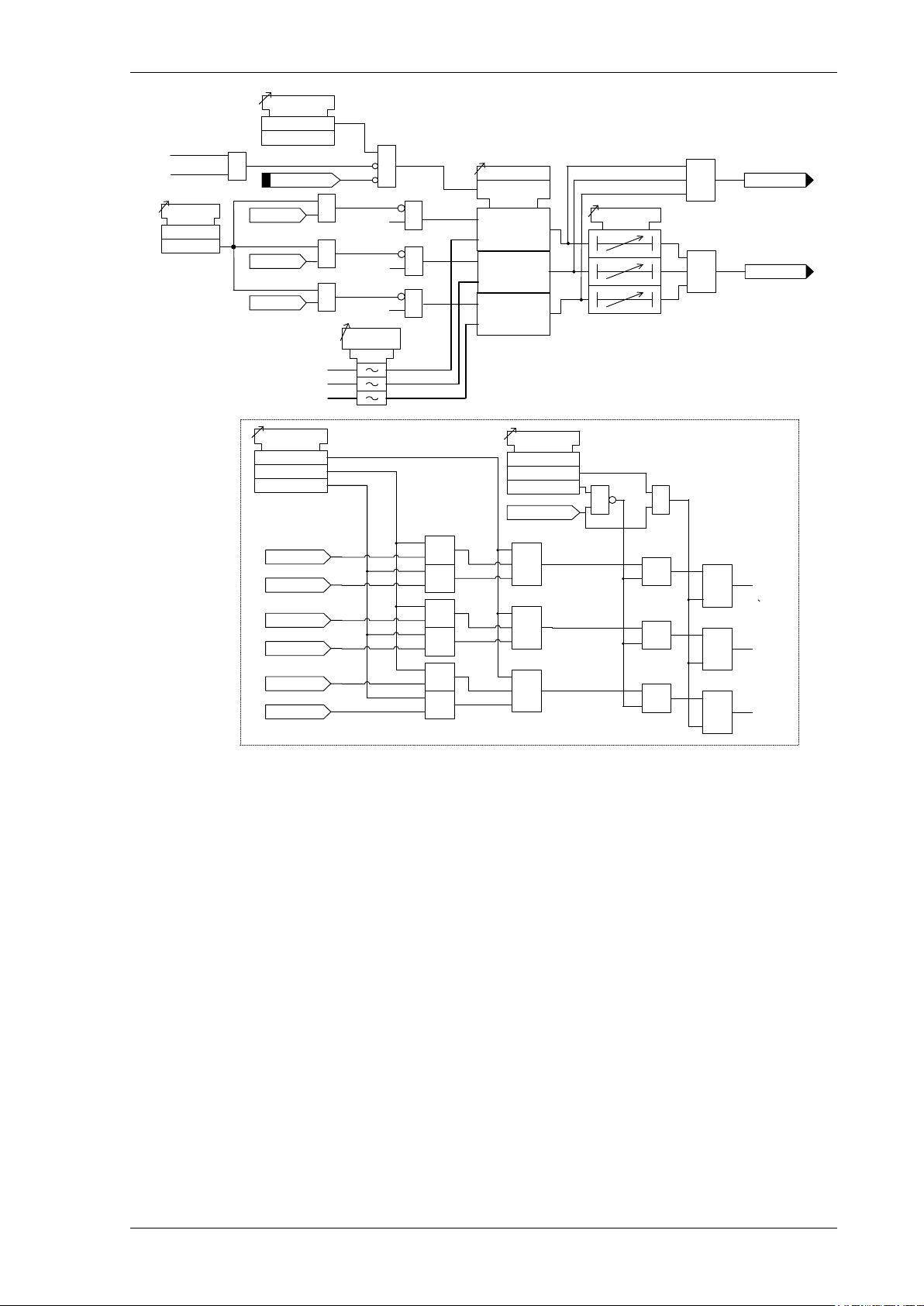
Figure 2-8 Binary Input Logic
2.11 Binary Outputs (Output Relays)
Relays are fitted with 3 or 6 binary outputs (BO). All outputs are fully user configurable and can be programmed to
operate from any or all of the available functions.
In the default mode of operation, binary outputs are self reset and remain energised for a user configurable
minimum time of up to 60 s. If required, the outputs can be programmed to operate as ‘hand reset’ or ‘pulsed’. If
the output is programmed to be ‘hand reset’ and ‘pulsed’ then the output will be ‘hand reset’ only.
The binary outputs can be used to operate the trip coils of the circuit breaker directly where the trip coil current
does not exceed the 'make and carry' contact rating. The circuit breaker auxiliary contacts or other in-series
auxiliary device must be used to break the trip coil current.
Any BO can be assigned as a ‘Trip Contact’ in the OUTPUT CONFIG > TRIP CONFIG menu. Operation of a ‘Trip
Contact’ will operate any LED or virtual assigned from the 'Trip Triggered feature in the same menu and will
initiate the fault record storage, actuate the ‘Trip Alert’ screen where enabled and CB Fail protection when
enabled.
©2018 Siemens Protection Devices Limited Chapter 1 Page 21 of 77
7SR10 Description of Operation
Event
Output 1
Min Operate Time
Hand Reset
BO 1 hand reset
S
R
Q
OUTPUT CONFIG>
OUTPUT MATRIX
(Or gates)
Logic signals,
e.g. '51-1'
Reset LEDs & Outputs (TEST/RESET key, Binary Input, Data Comms)
&
&
&
≥1
≥1
Event
Output n
BO n hand reset
S
R
Q
&
&
&
≥1
≥1
BO 1
BO n
OUTPUT
CONFIG>
BINARY
OUTPUT
CONFIG
OUTPUT
CONFIG>
BINARY
OUTPUT
CONFIG
Where a protection function is mapped to an output contact, the output contact can be configured to trigger when
the protection function picks-up rather than when it operates. Such output contacts are configured via the
OUTPUT CONFIG > BINARY OUTPUT CONFIG > Pickup Outputs setting.
Notes on Pulsed Outputs
When operated, the output will reset after a user configurable time of up to 60 s regardless of the initiating
condition.
Notes on Self Reset Outputs
Self reset operation has a minimum reset time of 100 ms.
With a failed breaker condition, the relay may remain operated until current flow is interrupted by an upstream
device. When the current is removed, the relay will then reset and attempt to interrupt trip coil current flowing vi a
its output contact. When this current level is above the break rating of the output contact, an auxiliary relay with
heavy-duty contacts should be utilised in the primary system to avoid damage to the relay.
Notes on Hand Reset Outputs – 86 Lockout
Any binary output can be programmed to provide an 86 lockout function by selecting it to be hand reset. Hand
reset outputs can be reset by either pressing the TEST/RESET► button, by energising a suitably programmed
binary input, or, by sending an appropriate command over the data communications channel(s).
On loss of the auxiliary supply hand-reset outputs wil l reset. When the auxiliary supply is
re-established the binary output will remain in the reset state unless the initiating condition is still present.
Notes on General Pickup
An output, General Pickup, is available to indicate that the pickup level has been exceeded for one or more
protection functions. Any protection function can be mapped to trigger this output in the OUTPUT CONFIG >
PICKUP CONFIG menu.
2.12 Virtual Input/Outputs
The relays have 8 virtual input/outputs these are internal binary stores. By assigning the status of data items like
starters, alarms, and equations to a virtual input/output, the status of these items can be used to fulfil higher levels
Figure 2-9 Binary Output Logic
of functionality.
The status of various data items can be assigned to virtual inputs/outputs using the INPUT CONFIG > OUTPUT
MATRIX menu.
Virtual input/outputs can be used as inputs to various functions including blocks, inhibits, triggers, and alarms
using the INPUT CONFIG > INPUT MATRIX menu.
Virtual input/outputs can also be used as data items in equations.
The status of the virtual inputs and outputs is volatile i.e. not stored during power loss.
©2018 Siemens Protection Devices Limited Chapter 1 Page 22 of 77
7SR10 Description of Operation
2.13 Self Monitoring
The relay incorporates a number of self-monitoring features. Each of these features can initiate a controlled reset
recovery sequence.
Supervision includes a power supply watchdog, code execution watchdog, memory checks by checksum, and
processor/ADC health checks. When all checks indicate the relay is operating correctly the ‘Protection Healthy’
LED is illuminated.
If an internal failure is detected, a message will be displayed. The relay will reset in an attempt to rectify the
failure. This will result in de-energisation of any binary output mapped to ‘protection healthy’ and flashing of the
protection healthy LED. If a successful reset is achieved by the relay, the LED and output contact will revert back
to normal operational mode and the relay will restart, therefore ensuring the circuit is protected for the maximum
time.
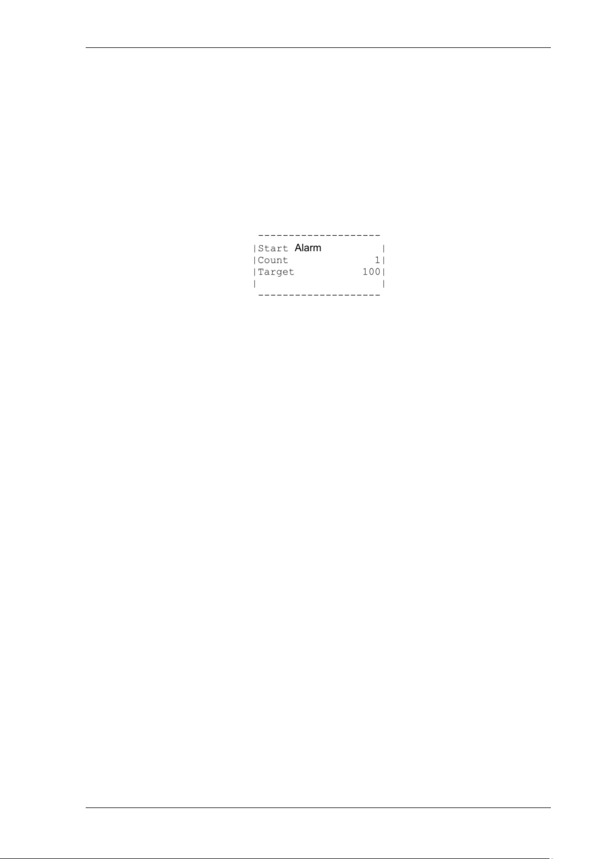
A start-up counter meter is provided to display the num ber of start-ups the relay has performed. Once the number
of start-ups has exceeded a set number, an alarm output can be given.
Figure 2-10 Start-up Counter Meter
Reset of the counter can be done from the meter or via a binary input or a command.
Various types of start-up are monitored by the relay:
1. power-on starts
2. expected starts (user initiated via communications)
3. unexpected starts (caused by the relay watchdog)
Any combination of these can be selected for the start-up count. This is done in the MAINTENANCE MENU >
START COUNT menu using the Start Types setting. All the start-up types selected (ticked) will be added to the
overall start-up count.
The number of restarts before the alarm output is raised is set in the MAINTENANCE MENU > START COUNT
menu using the Start Count Target setting.
When the number of relay start-ups reaches the target value an output is raised, OUTPUT MATRIX > Start
Count Alarm, which can be programmed to any combination of binary outputs, LED’s or virtual outputs.
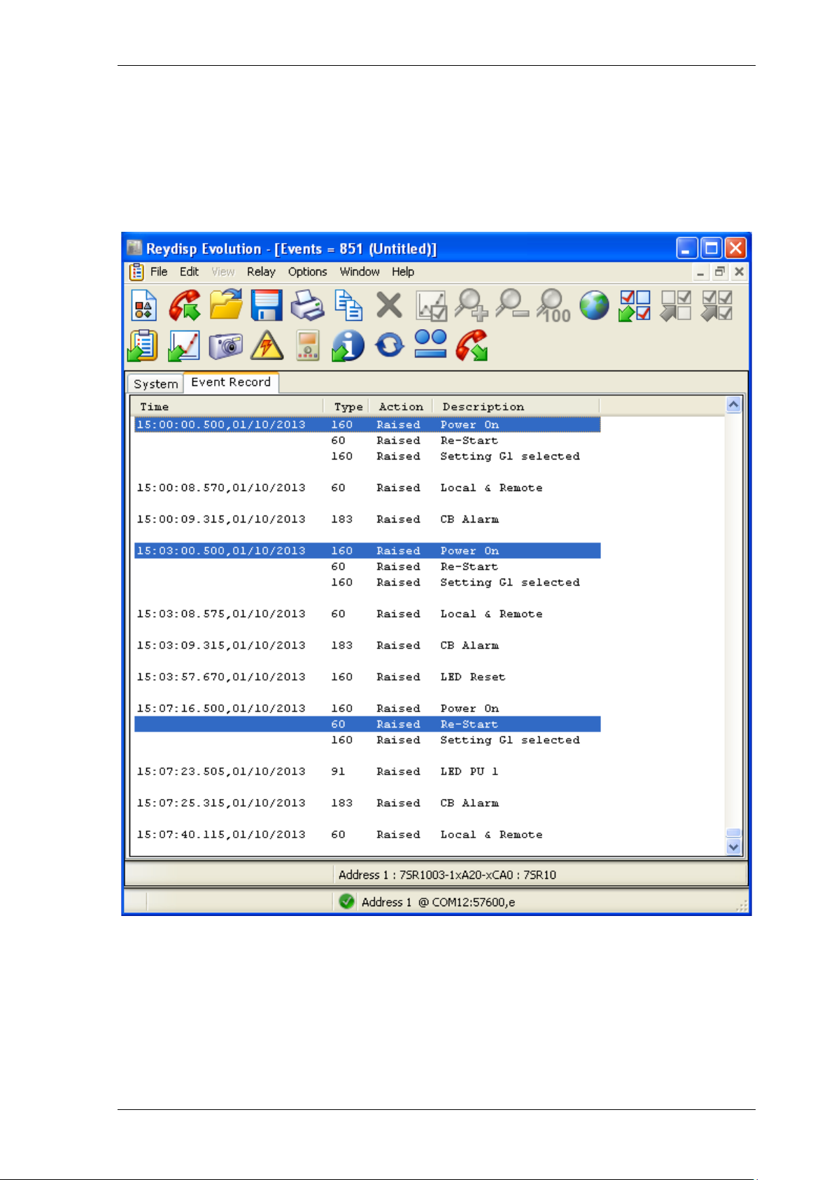
The following screen-shot show the events which are generated when the relay restarts. The highlighted events
show the cause of the re-start. The event which comes next shows the type of restart followed by the relay:
Warm, Cold or Re-Start.
As a further safeguard, if the Rel ay performs a number of unexpected starts SYSTEM CONFIG>Unexpected
Restart Count in a given time SYSTEM CONFIG>Unexpected Restart Period, it can be configured using the
SYSTEM CONFIG>Unexpected Restart Blocking setting to remove itself from service. In this case the Rel ay
will display an error message:
|UNEXPECTED RESTART |
|COUNTS EXCEEDED! |
|DEVICE LOCKED OUT |
| |
--------------------
Figure 2-11 Unexpected Restarts Lockout Text
And enter a locked-up mode. In this mode the Relay will disable operation of all LED’s and Binary Outputs,
including Protection Healthy, all pushbuttons and any data communications.
Once the Relay has failed in this manner, it is non-recoverable at site and must be returned to the manufacturer
for repair.
A meter, Miscellaneous Meters>Unexpected Restarts, is provided to show how many Unexpected Restarts have
occurred during the previous Unexpected Restart Period. This is resettable from the front fascia.
©2018 Siemens Protection Devices Limited Chapter 1 Page 23 of 77
7SR10 Description of Operation
2.13.1 Protection Healthy/Defective
When the relay has an auxiliary supply and it has successfully passed its self-checking procedure, then the front
fascia Protection Healthy LED is turned on.
A changeover or open contact can be mapped via the binary output matrix to provide an external protection
healthy signal.
A changeover or closed contact can be mapped via the binary output matrix to provide an external protection
defective signal. With the ‘Protection Healthy’ this contact is open. When the auxiliary supply is not applied to the
relay or a problem is detected within the relay then this output contact closes to provide external indication.
Figure 2-12 Start-up Events
©2018 Siemens Protection Devices Limited Chapter 1 Page 24 of 77

7SR10 Description of Operation
Section 3: Protection Functions
3.1 Current Protection: Phase Overcurrent (67, 51, 50)
All phase overcurrent elements have a common setting for the 50 elements and 51 elements to measure either
fundamental frequency RMS or True RMS current:
True RMS current: 50 Measurement = RMS, 51 Measurement = RMS
Fundamental Frequency RMS current: 50 Measurement = Fundamental, 51 Measurement =
Fundamental
3.1.1 Directional Control of Overcurrent Protection (67)
The directional element produces forward and reverse outputs for use with overcurrent elements. These outputs
can then be mapped as controls to each shaped and instantaneous over-current element.
If a protection element is set as non-directional then it will operate independently of the output of the directional
detector. However, if a protection element is programmed for forward directional mode then operation will occur
only for a fault lying within the forward operate zone. Conversely, if a protection element is programmed for
reverse directional mode then operation will occur only for a fault lying within the reverse operate zone. Typically
the forward direction is defined as being ‘away’ from the busbar or towards the protected zone.
The Characteristic angle is the phase angle by which the polarising voltage must be adjusted such that the
directional detector gives maximum sensitivity in the forward operate zone when the current is in phase with it.
The reverse operate zone is the mirror image of the forward zone.
Voltage polarisation is achieved for the phase-fault elements using the quadrature voltage i.e. at unity power
factor I leads V by 90°. Each phase current is compared to the voltage between the other two phases i.e for
normal phase sequence 1-2-3:
~ V23 IL2 ~ V31 I
I
L1
When the device is applied to reverse sequence networks, i.e. 1-3-2, the polarizing is corrected internally by the
Gn Phase Rotation setting in the CT/VT Config menu.
The characteristic angle can be user programmed to any angle between -95° and +95° using the 67 Char Angle
setting. The voltage is the reference phasor (Vref) and the 67 Char Angle setting is added to this to adjust the
forward and reverse zones.
The centre of the forward zone is set by (Vref Angle + 67 Char Angle) and should be set to correspond with Ifault
Angle for maximum sensitivity i.e.
For fault current of -60° (I lagging V by 60°) a 67 Char Angle of +30° is required for maximum sensitivity
(i.e. due to quadrature connection 90° - 60° = 30°).
OR
For fault current of -45° (I lagging V by 45°) a 67 Char Angle of +45° is required for maximum sensitivity
(i.e. due to quadrature connection 90° - 45° = 45°).
~ V
L3
12
Two-out-of-three Gate
When the 67 2-Out-Of-3 Logic setting is set to Enabled, the directional elements will only operate for the
majority direction, e.g. if I
flow, phases L
and L3 will operate forwards, while phase L2 will be inhibited.
1
and IL3 are detected as forward flowing currents and IL2 is detected as reverse current
L1
Minimum Polarising Voltage
The 67 Minimum Voltage setting defines the minimum polarising voltage level. Where the measured polarising
voltage is below this level no directional control signal is given and operation of protection elements set as
directional will be inhibited. This prevents mal-operation under fuse failure/MCB tripped conditions where noise
voltages can be present.
©2018 Siemens Protection Devices Limited Chapter 1 Page 25 of 77
7SR10 Description of Operation
V
23
I
L1
V
31
2
-out-of-3
logic
(fwd)
V
12
I
L3
I
L2
fwd
rev
fwd
rev
fwd
rev
2
-out-of-3
logic
(rev)
67
2-
Out-Of-3 Logic
67 Min
. Voltage
67
Charact
. Angle
L1 Fwd
L1 Rev
L3 Fwd
L2 Fwd
L3 Rev
L2 Rev
Directional
Control Signal
Figure 3-1 Logic Diagram: Directional Overcurrent Element (67)
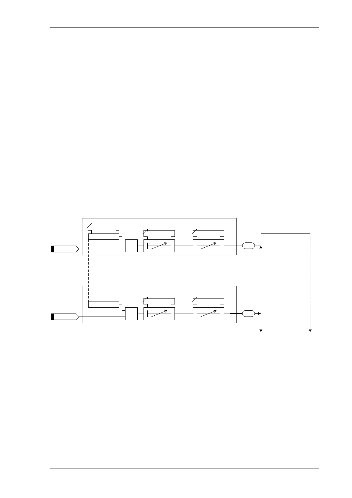
3.1.2 Instantaneous Overcurrent Protection (50)
Two Instantaneous overcurrent elements are provided in the 7SR1002/7SR1003 relay and four elements are
provided in the 7SR1004 relay.
50-1, 50-2, (50-3 & 50-4 – 7SR1004)
Each instantaneous element (50-n) has independent settings. 50-n Setting for pick-up current and 50-n Delay
follower time delay. The instantaneous elem ents have transient free operation.
Where directional elements are present the direction of operation can be set using 50-n Dir. Control setting.
Directional logic is provided independently for each 50-n element, e.g. giving the option of using two elements set
to forward and two to reverse.
Operation of the instantaneous overcurrent elements can be inhibited from:
Inhibit 50-n A binary or virtual input.
79 P/F Inst Trips: 50-n When ‘delayed’ trips only are allowed in the auto-reclose sequence
(79 P/F Prot’n Trip n = Delayed).
50-n Inrush Action: Block Operation of the inrush current detector function.
50-n VTS Action: Inhibit Operation of the VT Supervision function.
©2018 Siemens Protection Devices Limited Chapter 1 Page 26 of 77
7SR10 Description of Operation
≥1
Inhibit 50-n
50-n
50-n Set ting
c
50-n
Enabl ed
Disa bled
>
c
50-n D elay
If d irection al eleme nts are not
presen t this block is om itted and all
'Lx D ir En' signa ls are set TRU E.
Forw ard
Rever se
50-n D ir Cont rol
Non-D ir
≥1
&
&
≥1
&
&
≥1
&
&
L1 Di r En
L2 Di r En
L3 Di r En
IL1 Fwd
IL1 Rev
IL2 Fwd
IL2 Rev
IL3 Fwd
IL3 Rev
&
&
&
≥1
≥1
≥1
50-n VTS Action
Off
Non Di r
Inhibit
VT Fail
& &
>
c
>
c
L1 Di r En
L2 Di r En
L3 Di r En
IL1
IL2
IL3
50/51
Measurement
L1 81HBL2
50-n Inr ush
Ac tion
Off
Inhibit
&
L2 81HBL2
L3 81HBL2
&
&
&
&
&
≥1
General Pickup
&
&
79 P/F Inst Trips
= 50-n
79 P/F P rot’n Trip n
= Delayed
AUTORECLO SE
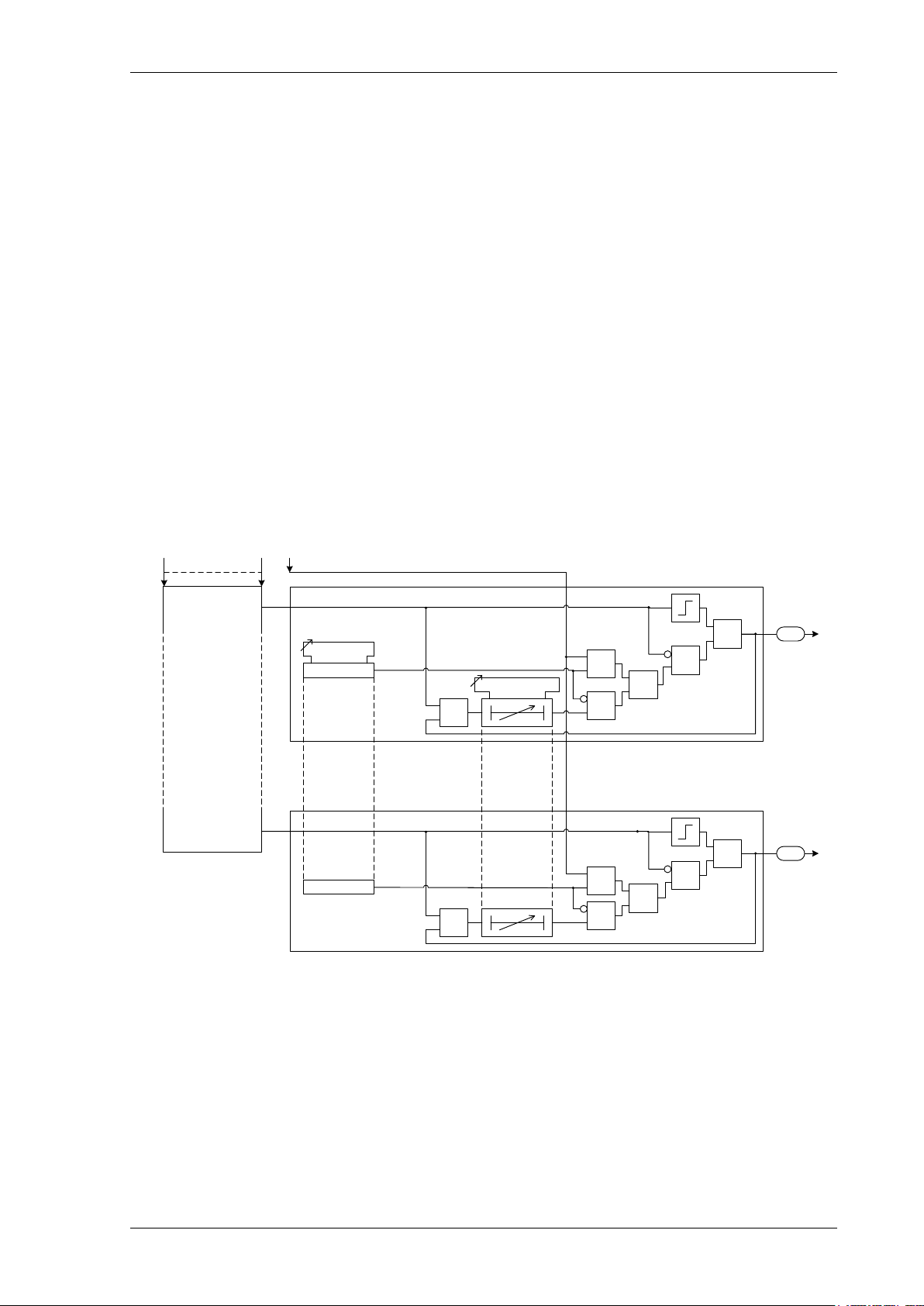
3.1.3 Time Delayed Overcurrent Protection (51)
Two time delayed overcurrent elements are provided in the 7SR1002/7SR1003 relay and four elements are
provided in the 7SR1004 relay.
51-n Setting sets the pick-up current level. Where the voltage controlled overcurrent function (51VCO) is used a
multiplier is applied to this setting where the voltage drops below the setting VCO Setting, see Section 3.1.4.
A number of shaped characteristics are provided. An inverse definite minimum time (IDMT) characteristic is
selected from IEC, ANSI or user specific curves using 51-n Char. A time multiplier is applied to the characteristic
curves using the 51-n Time Mult setting. Alternatively, a definite time lag delay (DTL) can be chosen using 51-n
Char. When Definite Tim e Lag (DTL) is selected the time multiplier is not applied and the 51-n Delay (DTL)
setting is used instead. Operating curve characteristics are illustrated in Chapter 3 – ‘Performance Specification’.
The 51-n Reset setting can apply a definite time delayed reset, or when the operation is configured as an IEC or
ANSI or user characteristic if the reset is selected as (IEC/ANSI) DECAYING reset the associated reset curve will
Figure 3-2 Logic Diagram: Instantaneous Over-current Element
be used. The reset mode is significant where the characteristic has reset before issuing a trip output – see
‘Applications Guide’.
A minimum operate tim e for the characteristic can be set using 51-n Min. Operate Time setting.
A fixed additional operate time can be added to the characteristic using 51-n Follower DTL setting.
Where directional elements are present the direction of operation can be set using 51-n Dir. Control setting.
Directional logic is provided independently for each 51-n element e.g. giving the option of using two elements set
to forward and two to reverse.
©2018 Siemens Protection Devices Limited Chapter 1 Page 27 of 77
51-1, 51-2, (51-3 & 51-4 – 7SR1004)
 Loading...