

Sherwood P1710X, P1710A, P1726X, P1732X, P1732A Technical Manual
...
The Original Engine Cooling Pump Since 1921
17000 and 27000 Pump Series Technical Guide
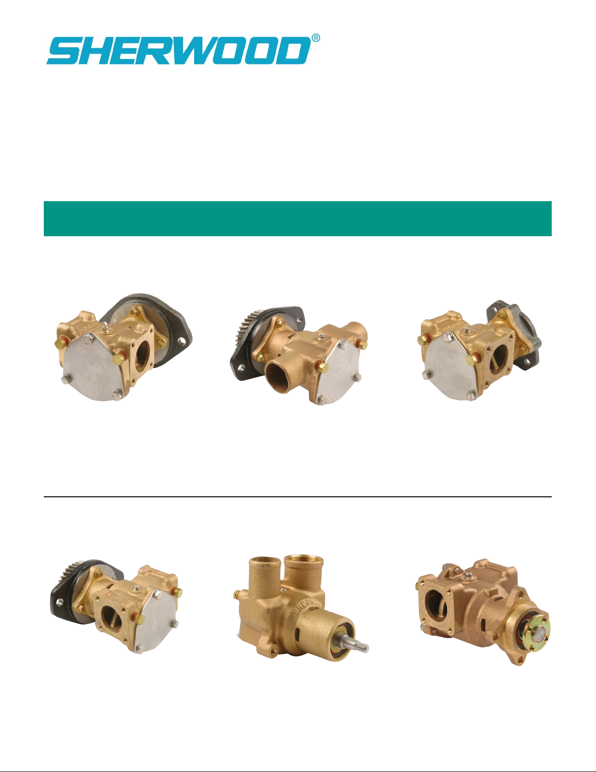
Identification
P1710X, P1710A,
P1726X, P1732X
& P1732A
P1727X, P1727A,
P1730X, P1730A, P1731,
and P1733X
P1716X, P1722X,
& P173
P176X
P1719X
P2701X

25
24
Assembly / Disassembly Instructions
10
0
2
19
21
15
13
11
8
4
3
1
3
2
16
12
9
18
14
10
6
7
5
2
The following assembly/disassembly procedures apply to all 17000 Series pumps. Deviations from pump to pump are
primarily a result of different methods of drive and mounting. Pump model numbers can be found stamped into the
cover plate of the pump.
Disassembly:
A. Remove the three bolts (1) and lock washers (2) from the pump cover (3). The cover and o-ring (4) are now free.
The impeller end cap (5) can be pried off with a screwdriver. Normally, impellers (7) can be removed by using the
23631 impeller puller (or 3/4” – 16 bolt) for the 17000 threaded impeller, the 24412 impeller puller (or M16 x 1.5
bolt) for the 27000 threaded impeller, or by using two pair of pliers to grip two of the impeller’s vanes on opposite
sides of the impeller. A penetrating lubricant will help loosen a stuck impeller. Also, rotating the shaft by hand may
help free the impeller. The 3/16” key (6) will also be removed at this time.
B. Remove any pulleys or drive gears (25) from the drive shaft. For tapered shaft models (all models except P173,
P1719, and P2701), it is necessary to remove the shaft nut and pull the gear or pulley with a puller. For models
with pressed on gears (P173), two threaded holes are provided in the gear. An appropriate puller may be attached
to these two holes to remove the gear from the shaft. The drive hub on the P2701 pump must be removed
with a bearing puller.
C. Most models will be equipped with a flange adapter (24). The flange adapter is held to the pump body by
two socket head cap screws (21), either 3/8" or 10mm, depending on the model. The screws are removed by using
a hex socket wrench. More current models are mounted with four 8mm flange hex head bolts. The adapter is then
removed. If the lip seal (23) in the adapter requires replacing, it can be pressed out at this time.
D. The cam (8) and cam screw (9) are removed. The internal wear plate (13) will drop out. The retaining ring (10),
washer (11) and seal seat (14) are then removed.
E. From the ball bearing end, the internal snap ring (17) must be removed on models P171 through P176, and
P2701. Later models have extended bearing assemblies and are held together by means of the flanged adapter.
The shaft/bearing assembly (19) is pressed out of the body from the impeller end of the housing removed from the
engine end of the pump. The two external snap rings (10) are removed from the shaft (19) along with the bearing
washers (12), permitting removal of bearings (20).
side of the housing (18).
The mechanical seal (15) may now be pressed from the bearing
Warning: If a shaft/bearing assembly exists for the particular model that is being repaired, do not try to build the
shaft/bearing assembly from the individual parts, but instead purchase the entire assembly
. Due to extremely tight tolerances, special assembly procedures for this assembly must be followed to prevent galling and subsequent leakage
in the oil seal area of the pump.
Reassembly:
A. Press mechanical seal (15) into housing (18) with the grey silicon carbide or black carbon seal face toward the impeller.
B. On all older model pumps with mounting adapters, the lip seal (23) will have to be replaced prior to replacing the
flange adapter (24). Care should be taken to insure proper alignment of the lip seal to the adapter and that the lip seal is
uniformly pressed to prevent distortion. The metal backing ring of the lip seal goes toward the pump and away from the engine.
C. Skip this step if the entire shaft/bearing assembly is available for the particular model that is being repaired. Install external
snap ring (10) on shaft (19). Next, place washer (12), bearing (20), bearing spacer (16), second bearing (20) and washer (12)
and secure with the second external snap ring (10). The bearings will have to be pressed on from the pulley/gear end. Note
that it is extremely important to properly align the bearings to the shaft prior to press, otherwise the possibility exists of galling
the shaft in the area of the lip seal. This completes the bearing and shaft assembly.
2
 Loading...