

Page 1
XG-P20XU
XG-P20XE
XG-P20XD
SERVICE MANUAL
SERVICE-ANLEITUNG
S51T3XG-P20XU
LCD PROJECTOR
LCD PROJEKTOR
XG-P20XU
XG-P20XE
MODELS
MODELLE
In the interests of user-safety (Required by safety regulations in some countries) the set should be restored
to its original condition and only parts identical to those specified should be used.
Im lnteresse der Benutzersicherheit (erforderliche Sicherheitsregeln in einigen Ländern) muß das Gerät in seinen
Originalzustand gebracht werden. Außerdem dürfen für die spezifizierten Bauteile nur identische T eile verwendet
werden.
XG-P20XD
SHARP CORPORATION
This document has been published to be used for
after sales service only.
The contents are subject to change without notice.
1
Page 2

XG-P20XU
XG-P20XE
XG-P20XD
• SPECIFICATIONS ............................................. 3
• IMPORTANT SERVICE SAFETY
NOTES (for USA)............................................... 4
• NOTE TO SERVICE PERSONNEL ................... 5
• OPERATION MANUAL ...................................... 8
• REMOVING OF MAJOR PARTS ..................... 12
• RESETTING THE TOT AL LAMP TIMER ......... 19
• THE OPTICAL UNIT OUTLINE........................ 20
• CONVERGENCE AND FOCUS
ADJUSTMENT................................................. 21
• ELECTRICAL ADJUSTMENT.......................... 28
• TROUBLE SHOOTING TABLE........................ 36
• CHASSIS LAYOUT .......................................... 82
CONTENTS
Page Page
• BLOCK DIAGRAM ........................................... 84
• OVERALL WIRING DIAGRAM ........................ 86
• DESCRIPTION OF SCHEMATIC DIAGRAM... 88
• WAVEFORMS .................................................. 89
• SCHEMATIC DIAGRAM .................................. 90
• PRINTED WIRING BOARD ASSEMBLIES ... 122
• PARTS LIST
Ë
ELECTRICAL PARTS............................... 129
Ë
CABINET AND MECHANICAL PARTS .... 147
Ë
ACCESSORIES PARTS........................... 152
Ë
PACKING PARTS..................................... 152
• PACKING OF THE SET ................................. 153
Seite Seite
• TECHNISCHE DATEN..................................... 44
• HINWEISE FÜR DAS
WARTUNGSPERSONAL................................. 45
• BEDIENUNGSANLEITUNG............................. 46
• ENTFERNEN DER HAUPTTEILE ................... 50
• RÜCKSTELLEN DES
LAMPENBETRIEBSZEIT-TIMERS.................. 57
• ÜBERSICHT DER OPTIK-EINHEIT................. 58
• EINSTELLUNG VON KONVERGENZ UND
BRENNPUNKT ................................................ 59
• ELEKTRISCHE EINSTELLUNG ...................... 66
• FEHLERSUCHTABELLE ................................. 74
• CHASSIS-ANORDNUNG ................................ 82
• BLOCKSCHALTBILD ....................................... 84
INHALT
• GESAMTSCHALTPLAN................................... 86
• BESCHREIBUNG DES SCHEMATISCHEN
• WELLENFORMEN........................................... 89
• SCHEMATISCHER SCHALTPLAN.................. 90
• LEITERPLATTENEINHEITEN ....................... 122
• ERSATZTEILLISTE
• VERPACKEN DES GERÄTS ......................... 153
SCHALTPLANS ............................................... 88
Ë
ELEKTRISCHE BAUTEILE ...................... 129
Ë
CEHÄUSE UND MECHANISCHE
BAUTEILE ................................................ 147
Ë
ZUBEHÖRTEILE...................................... 152
Ë
VERPACKUNGSTEILE ............................ 152
2
Page 3

Specifications
XG-P20XU
XG-P20XE
XG-P20XD
Product type
Model
Video system
LCD Projector
XG-P20XU/XE/XD
PAL/PAL 60/PAL-M/PAL-N/SECAM/NTSC 3.58/NTSC 4.43
DTV 480P/720P/1080i
Display method
LCD panel
LCD panel × 3,RGB optical shutter method
Panel size:1.3" (20.0 [H ] × 26.6 [W ] mm))
Display method:Translucent TN liquid crystal panel
Drive method:TFT (Thin Film Transistor)Active Matrix panel
No.of dots:786,432 dots (1,024 [H ] × 768 [V ])
Standard Lens
Projection lamp
Contrast ratio
Video input signal
1 –1.3 × zoom lens, F1.7 – 2.3, f =49.1 – 63.8 mm
AC 220 W lamp
600:1
RCA Connector:VIDEO, composite video, 1.0 Vp-p,sync negative, 75Ω terminated
RCA Connector:AUDIO, 0.5 Vrms more than 22 kΩ (stereo)
S-video input signal
4-pin Mini DIN connector
Y (luminance signal):1.0 Vp-p, sync negative, 75Ω terminated
C (chrominance signal):Burst 0.286 Vp-p, 75Ω terminated
Component input signal
BNC Connector (INPUT 2)
Y:1.0 Vp-p,sync negative, 75Ω terminated
B
:0.7 Vp-p, 75Ω terminated
P
P
R
:0.7 Vp-p, 75Ω terminated
Horizontal resolution
RGB input signal
520 TV lines (S-video input), 750 TV lines (DTV 720P input, STRETCH mode)
15-PIN MINI D-SUB CONNECTOR (INPUT 1), 5 BNC CONNECTOR (INPUT 2):
RGB separate/composite sync/sync on green type analog input:0 –0.7 Vp-p, positive,
75Ω terminated
Pixel clock
Vertical frequency
Horizontal frequency
Computer control signal
Speaker system
CONNECTOR
DVI
H
ORIZONTAL SYNC.SIGNAL
V
ERTICAL SYNC.SIGNAL
TEREO MINIJACK
S
12 – 230 MHz
43 – 200 Hz
15 – 126 kHz
9-pin D-sub connector (RS-232C Input Port/Output Port)
49
⁄64"(4.5 cm) round × 2
1
(29-
PIN
)(INPUT 3), RGB (DIGITAL), 250 –1,000 mV, 50Ω
:TTL level (positive/negative) or composite sync (Apple only)
:Same as above
:AUDIO, 0.5 Vrms, more than 22 kΩ (stereo)
2 W + 2 W (stereo)
Rated voltage
Input current
Rated frequency
Power consumption
Power dissipation
Operating temperature
Storage temperature
Cabinet
GyroRemote
Dimensions (approx.)
AC 100 – 240 V
3.95 A
50/60 Hz
330 W
<1,250 BTU/hour
41 °F to 104 °F (+5 °C to +40 °C)
–4 °F to 140 °F (–20 °C to +60 °C)
Plastic
Radio Frequency Range:49.825 – 49.895 MHz
9
⁄16"(W) × 6 3 ⁄32"(H) × 16 21 ⁄32"(D)(319.0 × 155.0 × 423.0 mm)(main body only)
12
11
12
⁄32"(W) × 7 27 ⁄64"(H) × 17 15 ⁄64"(D)(322.5 × 188.5 × 438.0 mm)(including standard
lens, adjustment feet and projecting parts)
Weight (approx.)
Supplied accessories
21.0 lbs.(9.5 kg)
GyroRemote, Four AAA size batteries, Power cord (11'10",3.6 m), RGB cable (9'10",
3 m), USB mouse control cable (3'3",1 m), Computer audio cable (9'10",3 m), ø 2.5 –ø 3.5
mm wired remote control cable (6
Lens cap, CD-ROM, LCD projector operation manual, LCD projector quick guide, Sharp
Advanced Presentation Software operation manual, ID number seal
Replacement parts
Standard lens unit (CLNS-0236CE01), Lamp unit (Lamp/cage module)(BQC-XGP20X//1), GyroRemote
(RRMCG1631CESA for XG-P20XU, RRMCG1653CESA for XG-P20XE, CRMCG1654DE02 for XG-P20XD),
AAA size batteries, Power cord (QACCU5013CEZZ, QACCL3022CEZZ, QACCV4002CEZZ, QACCB5024CENA),
RGB cable (QCNW-5304CEZZ), USB mouse control cable (QCNW-5916CEZZ),Computer audio cable
(QCNW-4870CEZZ), ø 2.5 –ø 3.5 mm wired remote control cable (QCNW-5943CEZZ), BNC-RCA adaptors
(QPLGJ0107GEZZ), Air filter (PFILD0080CEZZ), Lens cap(PCAPH1056CESA), CD-ROM(UDSKA0043CEN1
for XG-P20XU, UDSKA0045CEN1 for XG-P20XE/XD), LCD projector operation manual (TINS-7354CEZZ for
XG-P20XU, TiNS-7403CEZZ for XG-P20XE, TiNS-7409CEZZ for XG-P20XD), LCD projector quick guide
(TINS-7355CEZZ for XG-P20XU, TiNS-7404CEZZ/TiNS-7405CEZZ for XG-P20XE, TiNS-7500CEZZ for
XG-P20XD), Sharp Advanced PresentationSoftware operation manual (TINS-7356CEZZ for XG-P20XU,
TiNS-7406CEZZ for XG-P20XE, TiNS-7407CEZZ for XG-P20XD), ID number seal (TLABZ0781CEZZ)
This SHARP projector uses LCD (Liquid Crystal Display)panels.These
very sophisticated panels contain 786,432 pixels (×RGB)TFTs (Thin
Film Transistors).As with any high technology electronic equipment
such as large screen TVs,video systems and video cameras,there
are certain acceptable tolerances that the equipment must conform
to.
Specifications are subject to change without notice.
45
⁄64",15 cm), Three BNC-RCA adaptors, Extra air filter,
This unit has some inactive TFTs within acceptable tolerances which
may result in illuminated or inactive dots on the picture screen.This
will not affect the picture quality or the life expectancy of the unit.
If you have any questions about this matter,please call toll free 1-888GO-SHARP (1-888-467-4277). U.S.A.ONLY
3
Page 4
XG-P20XU
2
2
XG-P20XE
XG-P20XD
IMPORTANT SERVICE SAFETY NOTES (for USA)
Ë Service work should be performed only by qualified service technicians who are
thoroughly familiar with all safety checks and servicing guidelines as follows:
WARNING
1. For continued safety, no modification of any circuit
should be attempted.
2. Disconnect AC power before servicing.
BEFORE RETURNING THE PROJECTOR:
(Fire & Shock Hazard)
Before returning the projector to the user, perform
the following safety checks:
1. Inspect lead wires are not pinched between the
chassis and other metal parts of the projector.
2. Inspect all protective devices such as non-metallic
control knobs, insulating materials, cabinet backs,
adjustment and compartment covers or shields,
isolation resistor-capacity networks, mechanical
insulators, etc.
3. To be sure that no shock hazard exists, check for
current leakage in the following manner:
» Plug the AC cord directly into a 120-volt AC outlet,
(Do not use an isolation transformer for this test).
» Using two clip leads, connect a 1.5k ohm, 10 watt
resistor paralleled by a 0.15µF capacitor in parallel
between all exposed metal cabinet parts and earth
ground.
» Use an AC voltmeter with sensitivity of 5000 ohm per
volt., or higher, sensitivity to measure the AC voltage
drop across the resistor (See Diagram).
» All checks must be repeated with the AC plug
connection reversed. (If necessary , a non-polarized
adapter plug must be used only for the purpose of
completing these checks.)
Any reading of 0.3 volts RMS (this corresponds to
0.2 milliamp. AC.) or more is excessive and indicates
a potential shock hazard which must be corrected
before returning the unit to the owner.
AC
VOLTMETER
1.5k ohm (10W)
0.15µF
TEST PROBE
TO EXPOSED
METAL PARTS
CONNECT TO KNOWN
EARTH GROUND
234567890123456789012345678901212345678901234567890123456789012123456789012345678901234567890121
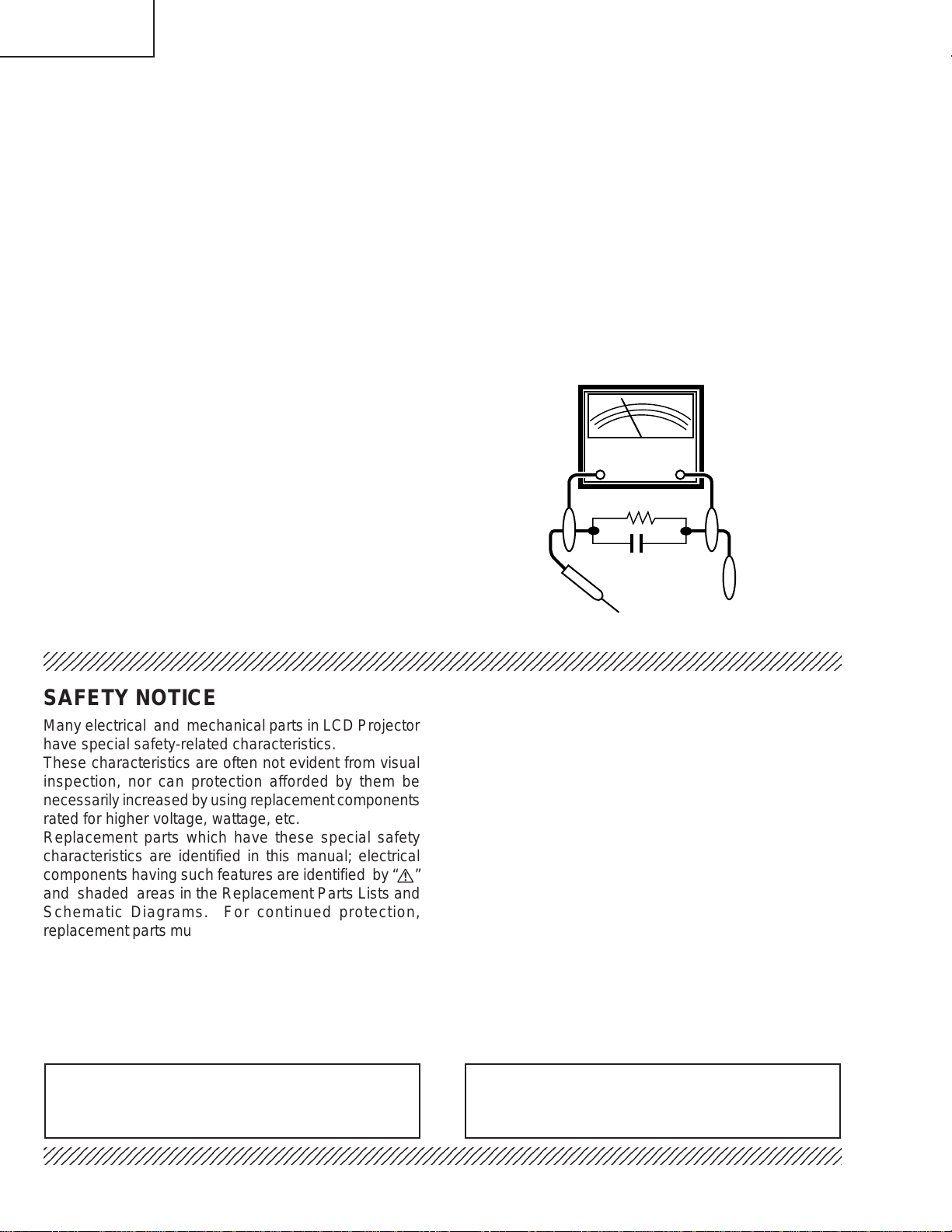
SAFETY NOTICE
Many electrical and mechanical parts in LCD Projector
have special safety-related characteristics.
These characteristics are often not evident from visual
inspection, nor can protection afforded by them be
necessarily increased by using replacement components
rated for higher voltage, wattage, etc.
Replacement parts which have these special safety
characteristics are identified in this manual; electrical
components having such features are identified by “å”
and shaded areas in the Replacement Parts Lists and
Schematic Diagrams. For continued protection,
replacement parts must be identical to those used in the
original circuit. The use of a substitute replacement parts
which do not have the same safety characteristics as
the factory recommended replacement parts shown in
this service manual, may create shock, fire or other
hazards.
AVIS POUR LA SECURITE
De nombreuses pièces, électriques et mécaniques, dans
les projecteur à LCD présentent des caractéristiques
spéciales relatives à la sécurité, qui ne sont souvent
pas évidentes à vue.
Le degré de protection ne peut pas être nécessairement
augmentée en utilisant des pièces de remplacement
étalonnées pour haute tension, puissance, etc.
Les pièces de remplacement qui présentent ces
caractéristiques sont identifiées dans ce manuel;
les pièces électriques qui présentent ces particularités
sont identifiées par la marque “å” et hachurées dans la
liste des pièces de remplacement et les diagrammes
schématiques. Pour assurer la protection, ces pièces
doivent être identiques à celles utilisées dans le circuit
d’origine. L’utilisation de pièces qui n’ont pas les mêmes
caractéristiques que les pièces recommandées par
l’usine, indiquées dans ce manuel, peut provoquer des
électrocutions, incendies ou autres accidents.
WARNING: The bimetallic component has the primary
conductive side exposed. Be very careful in
handling this component when the power is on.
234567890123456789012345678901212345678901234567890123456789012123456789012345678901234567890121
AVERTISSEMENT: La composante bimétallique dispose du
conducteur primaire dénudé. Faire
attention lors de la manipulation de cette
composante sous tension.
4
Page 5
XG-P20XU
XG-P20XE
XG-P20XD
NOTE TO SERVICE
PERSONNEL
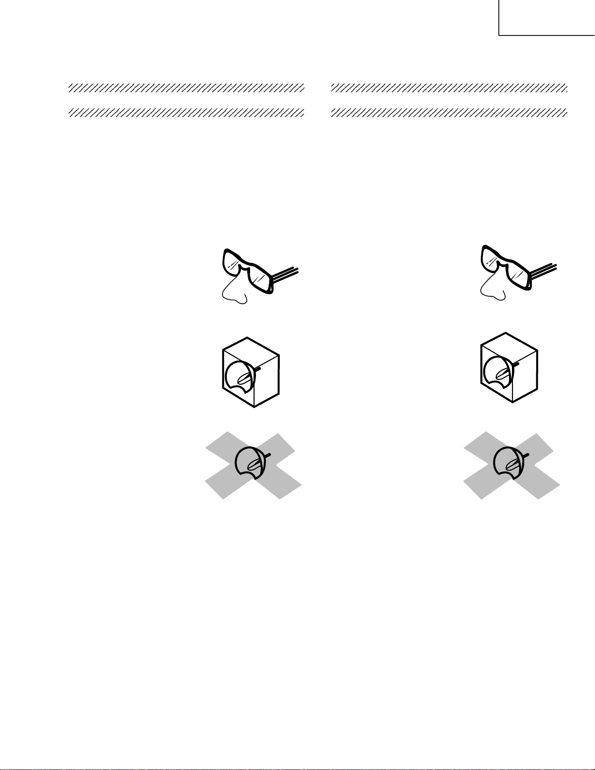
UV-RADIATION PRECAUTION
The light source, metal halide lamp, in the LCD
projector emits small amounts of UV-Radiation.
A VOID DIRECT EYE AND SKIN EXPOSURE.
To ensure safety please adhere to the following:
1. Be sure to wear sun-glasses when servicing the
projector with the lamp
turned “on” and the top
enclosure removed.
2. Do not operate the lamp outside of the lamp housing.
NOTE POUR LE PERSONNEL
D’ENTRETIEN
PRECAUTION POUR LES RADIA TIONS UV
La source de lumière, la lampe métal halide, dans le
projecteur LCD émet de petites quantités de radiation
UV .
EVITEZ TOUTE EXPOSITION DIRECTE
DES YEUX ET DE LA PEAU.
Pour votre sécurité, nous vous prions de respecter
les points suivants:
1. Toujours porter des lunettes de soleil lors d’un
entretien du projecteur
avec la lampe allumée
et le haut du coffret retiré.
2. Ne pas faire fonctionner la lampe à l’extérieur du
boîtier de lampe.
3. Do not operate for more than 2 hours with the
enclosure removed.
UV-Radiation and Medium Pressure
Lamp Precautions
1. Be sure to disconnect the AC plug when replacing
the lamp.
2. Allow one hour for the unit to cool down before
servicing.
3. Replace only with same type lamp. Type
CLMPF0072DE02 or BQC-XGP20X//1 rated 85V/
220W.
4. The lamp emits small amounts of UV-Radiation, avoid
direct-eye contact.
5. The medium pressure lamp involves a risk of
explosion. Be sure to follow installation instructions
described below and handle the lamp with care.
3. Ne pas faire fonctionner plus de 2 heures avec le
coffret retiré.
Précautions pour les radiations UV
et la lampe moyenne pression
1. Toujours débrancher la fiche AC lors du
remplacement de la lampe.
2. Laisser l’unité refroidir pendant une heure avant de
procéder à l’entretien.
3. Ne remplacer qu’avec une lampe du même type.
Type CLMPF0072DE02 ou BQC-XGP20XU//1
caractéristique 85V/220W.
4. La lampe émet de petites quantités de radiation UVéviter tout contact direct avec les yeux.
5. La lampe moyenne pression implique un risque
d’explosion. Toujours suivre les instructions
d’installation décrites ci-dessous et manipuler la
lampe avec soin.
5
Page 6
XG-P20XU
5
4
5
5
XG-P20XE
XG-P20XD
234567890123456789012345678901212345678901234
234567890123456789012345678901212345678901234
UV-RADIATION PRECAUTION (Continued)
23456789012345678901234567890121234567890123
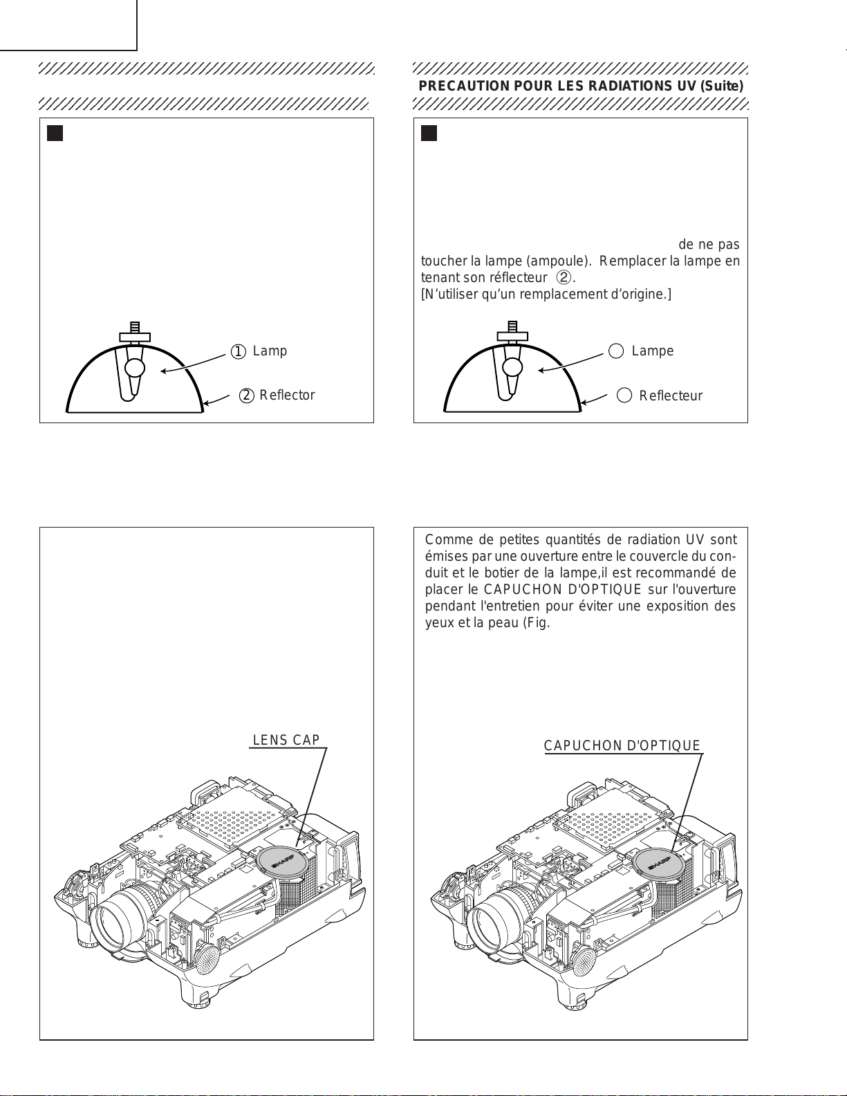
Lamp Replacement
Note:
Since the lamp reaches a very high temperature
during units operation replacement of the lamp
should be done at least one hour after the power
has been turned off. (to allow the lamp to cool off.)
Installing the new lamp, make sure not to touch the
lamp (bulb) replace the lamp by holding its reflector
2.
[Use original replacement only.]
Lamp
1
Reflector
2
DANGER ! –– Never turn the power on without the
lamp to avoid electric-shock or damage of the
devices since the stabilizer generates high voltages
at its start.
PRECAUTION POUR LES RADIATIONS UV (Suite)
234567890123456789012345678901212345678901234
Remplacement de la lampe
Remarque:
Comme la lampe devient très chaude pendant le
fonctionnement de l’unité, son remplacement ne doit
être effectué au moins une heure après avoir coupé
l’alimentation (pour permettre à la lampe de refroidir).
En installant la nouvelle lampe, s’assurer de ne pas
toucher la lampe (ampoule). Remplacer la lampe en
tenant son réflecteur 2.
[N’utiliser qu’un remplacement d’origine.]
1
Lampe
2
Reflecteur
DANGER ! –– Ne jamais mettre sous tension sans
la lampe pour éviter un choc électrique ou des
dommages des appareils car le stabilisateur génère
de hautes tensions à sa mise en route.
Since small amounts of UV-Radiation are emitted
from an opening between the duct cover and the
lamp housing, it is recommended to place the LENS
CAP on the opening during servicing to avoid eye
and skin exposure (Fig. 1).
Note: Please obtain a lens cap before servicing a
models XG-P20XU/XE/XD that is received
without one.
LENS CAP
Comme de petites quantités de radiation UV sont
émises par une ouverture entre le couvercle du conduit et le botier de la lampe,il est recommandé de
placer le CAPUCHON D'OPTIQUE sur l'ouverture
pendant l'entretien pour éviter une exposition des
yeux et la peau (Fig. 1).
Remarque: Priére de se procurer un capuchon
d'optique acant d'entretien un modéle
XG-P20XU/XE/XD qui est livré sans.
CAPUCHON D'OPTIQUE
Figure 1.
Figure 1.
6
Page 7
XG-P20XU
2
XG-P20XE
XG-P20XD
WARNING: High brightness light source, do not stare into the beam of light, or view directly . Be especially
careful that children do not stare directly in to the beam of light.
WARNING: TO REDUCE THE RISK OF FIRE OR ELECTRIC SHOCK, DO NOT EXPOSE THIS UNIT TO
MOISTURE OR WET LOCATIONS.
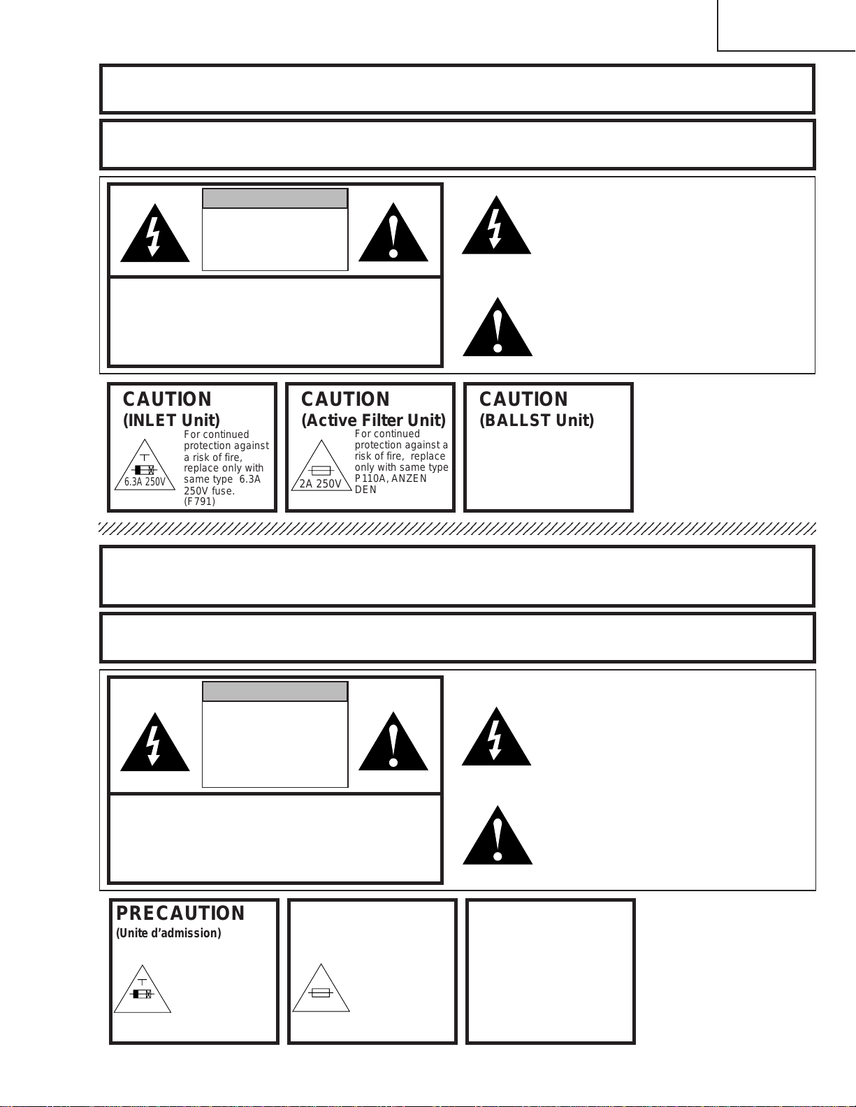
CAUTION
RISK OF ELECTRIC SHOCK.
DO NOT REMOVE SCREWS
EXCEPT SPECIFIED USER
SERVICE SCREW
CAUTION: TO REDUCE THE RISK OF ELECTRIC SHOCK,
NO USER-SERVICEABLE P ARTS EXCEPT LAMP UNIT.
CAUTION
(INLET Unit)
6.3A 250V
234567890123456789012345678901212345678901234567890123456789012123456789012345678901234567890121
DO NOT REMOVE CABINET.
REFER SERVICING TO QUALIFIED SERVICE
PERSONNEL.
CAUTION
For continued
protection against
a risk of fire,
replace only with
same type 6.3A
250V fuse.
(F791)
(Active Filter Unit)
2A 250V
For continued
protection against a
risk of fire, replace
only with same type
P110A, ANZEN
DENGU, 2A, 250V
117°C fuse.(TF701)
CAUTION
(BALLST Unit)
The lighting flash with arrowhead within a
triangle is intended to tell the user that
parts inside the product are risk of electric
shock to persons.
The exclamation point within a triangle is
intended to tell the user that important
operating and servicing instructions are in
the manual with the projector.
For continued
protection against a
risk of fire, replace
only with same type
P110A, ANZEN
DENGU, 2A, 250V
117°C fuse.(THP1701)
A VERTISSEMENT : Source lumineuse de grande intensité. Ne pas fixer le faisceau lumineux ou le regarder
directement. V eiller particulièrement à éviter que les enfants ne fixent directement le
faisceau lumineux.
A VERTISSEMENT : AFIN D’EVITER TOUT RISQUE D’INCENDIE OU D’ELECTROCUTION, NE P AS PLACER
CET APPAREIL DANS UN ENDROIT HUMIDE OU MOUILLE.
ATTENTION
RISQUE
D’ELECTROCUTION NE
PASRETIRER LES VIS, A
L’EXCEPTION DES VIS DE
REPARATION UTILISATEUR
SPECIFIEES
L’éclair terminé d’une flèche à l’intérieur
d’un triangle indique à l’utilisateur que les
pi‘eces se trouvant dans l’appareil sont
susceptibles de provoquer une décharge
électrique.
Le point d’exclamation à l’intérieur d’un
ATTENTION: POUR EVITER T OUT RISQUE
D’ELECTROCUTION, NE PAS RETIRER LE CAPOT.
AUCUNE DES PIECES INTERIEURES N’EST REP ARABLE
PAR L’UTILISA TEUR, A L’EXCEPTION DE L’UNITE DE
LAMPE. POUR TOUTE REPARA TION, S’ADRESSER A UN
PRECAUTION
(Unite d’admission)
6,3A 250V
TECHNICIEN D’ENTRETIEN QUALIFIE.
PRECAUTION
Pour une protection
continue contre les
risques d’incendie,
ne remplacer
qu’avec un fusible
6,3A 250V du même
type.
(F791)
(Unité de filtration active)
2A 250V
Pour une protection
continue contre un
risques d’incendie, ne
remplacer qu’avec un
fusible P110A, ANZEN
DENGU 2A 250V,
117°C du même type.
(TF701)
PRECAUTION
(Unité de PUTSSANCE)
triangle indique à l’utilisateur que les
instructions de fonctionnement et
d’entretien sont détaillées dans les
documents fournis avec le projecteur.
Pour une protection
continue contre un
risques d’incendie, ne
remplacer qu’avec un
fusible P110A, ANZEN
DENGU 2A 250V,
117°C du même type.
(THP1701)
7
Page 8
XG-P20XU
XG-P20XE
XG-P20XD
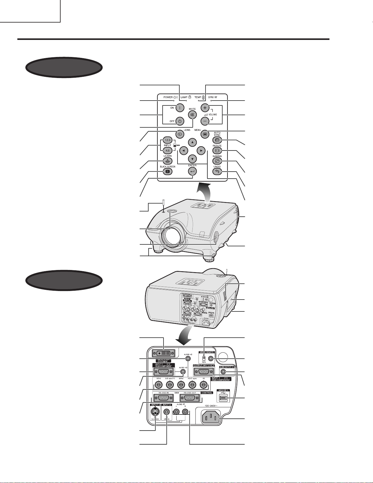
Location of Controls
Projector
Front View
LAMP REPLACEMENT indicator
POWER indicator
POWER buttons (ON/OFF)
MUTE button
LENS button
INPUT 1,2,3,4,5 buttons
LEARN button
BLACK SCREEN button
ENTER button
Antenna
Lens shift dial
Speakers
Foot releases
TEMPERATURE WARNING
indicator
GYRO RF indicator
VOLUME buttons (-/+)
MENU button
AUTO SYNC button
RESIZE button
GAMMA button
UNDO button
ADJUSTMENT buttons
('/"/\/|)
Cooling fan (Exhaust vent)
Air filter/Cooling fan
(Intake vent)
Rear View
INPUT 3 port (DVI)
Computer AUDIO INPUT 2/3 terminal
(ø 3.5 mm stereo minijack)
INPUT 1 port (15-pin Mini D-sub)
Computer AUDIO INPUT 1 terminal
(ø 3.5 mm stereo minijack)
INPUT 2 terminals (BNC)
RS-232C INPUT port/
RS-232C OUTPUT port
S-VIDEO INPUT 5 terminal
(4-pin Mini DIN)
VIDEO INPUT 4 terminal (RCA)
Cooling fan (Intake vent)
Kensington Security
Standard connector
Carrying handle
IR/Gyro switch
WIRED REMOTE control
input terminal
(ø 3.5 mm stereo minijack)
AUDIO OUTPUT terminal
(ø 3.5 mm stereo minijack)
OUTPUT port (15-pin Mini
D-sub)for INPUT 1,2
USB port
AC socket
AUDIO INPUT 4/5
terminals (RCA)
8
Page 9
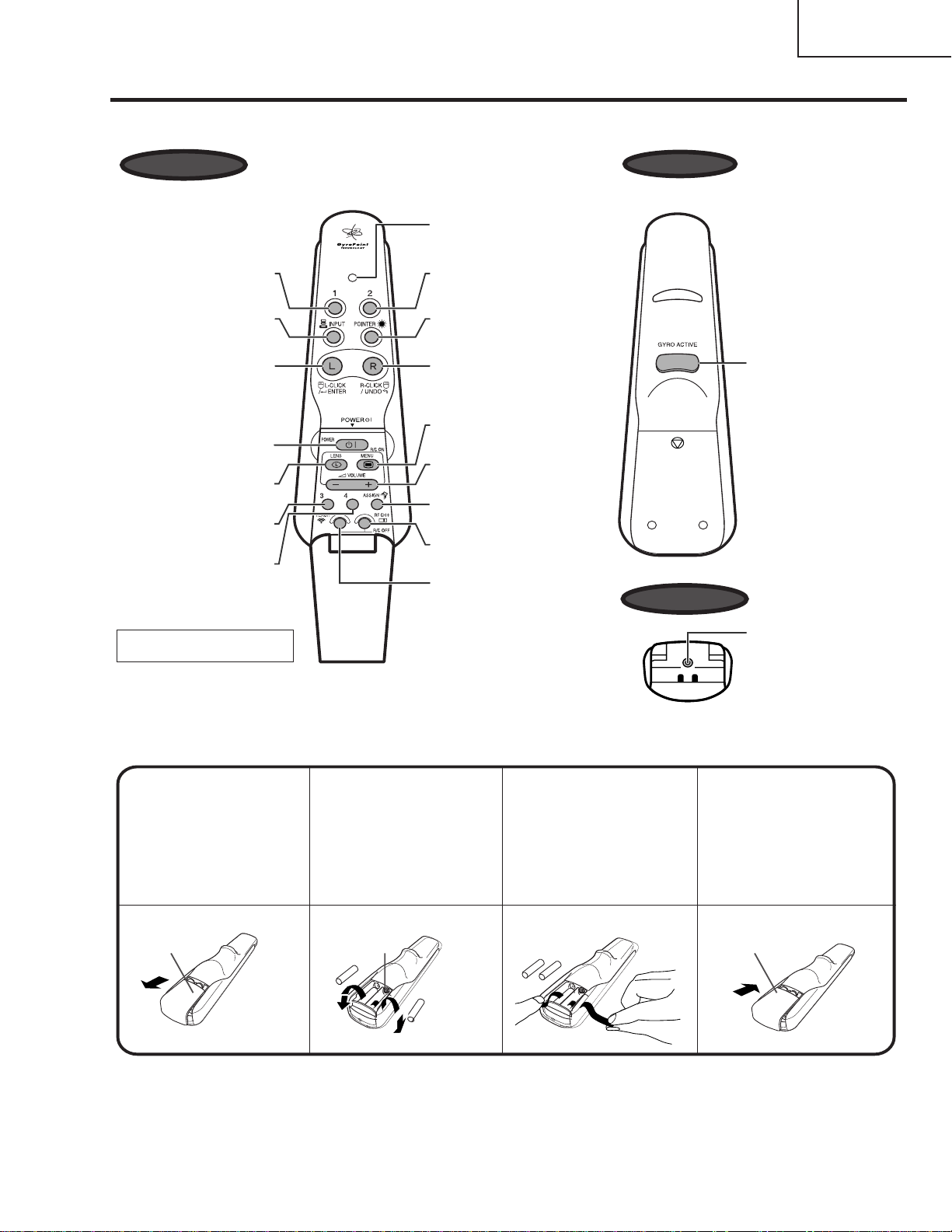
Operating the Wireless Mouse Remote Control
Remote Control
XG-P20XU
XG-P20XE
XG-P20XD
Front View
Function
button (1)
INPUT button
LEFT-CLICK/
ENTER button
POWER button
LENS button
Function
button (3)
Function
button (4)
Gyration U.S.Patents
5698784,5825350,5898421
LED
Function
button (2)
POINTER button
RIGHT-CLICK/
UNDO button
MENU button
VOLUME/
-/+button
ASSIGN Select
button
RF CH+ button
TEACH button
Rear View
GYRO ACTIVE
button
Bottom View
Wired remote
control input
Inserting and removing the batteries
Batteries are not pre-installed at the factory.When inserting batteries for the first time,follow steps 1,3 and 4
below.
Press in on the arrow
1
mark and slide in the
direction of the arrow
to remove the battery
cover.
Battery
cover
Remove the two
234
upper batteries and
pull the tapes to pick
up two other
batteries at the
bottom of the
compartment.
Battery
compartment
Insert four AAA size
batteries, making
sure the polarities
match the +andmarks inside the
battery compartment
and the batteries are
placed on the tapes.
Insert the side tabs
of the battery cover
into the slots and
press the cover in
until it is properly
seated.
Battery
cover
9
Page 10
XG-P20XU
XG-P20XE
XG-P20XD
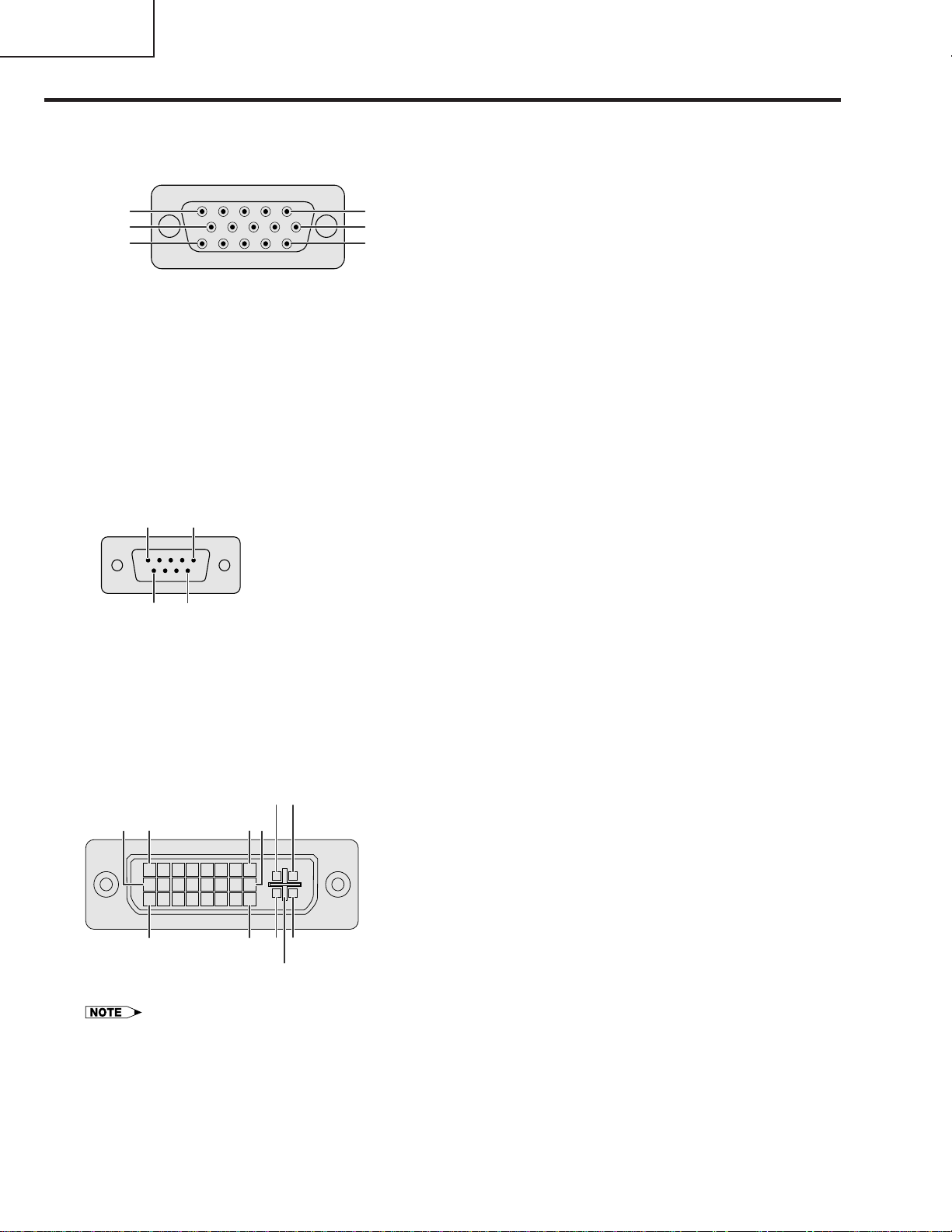
Connection Pin Assignments
INPUT 1 RGB and OUTPUT (INPUT 1, 2) Signal Ports:
RGB Input
Analog
1.Video input (red)
2.Video input
(green/sync on green)
3.Video input (blue)
4.Reserve input 1
5.Composite sync
6.Earth (red)
7.Earth (green/sync on green)
10
15
5
1
6
11
Component Input
Analog
1.PR (CR)
2.Y
3.PB (CB)
4.Not connected
5.Not connected
6.Earth (PR)
7.Earth (Y)
8.Earth (PB)
RS-232C Port:
15
6
9-pin D-sub male connector of the DIN-D-sub RS-232C cable
Pin No.
9
Signal
1
2
3
4
5
6
7
8
9
CD
RD
SD
ER
SG
DR
RS
CS
CI
Name
Receive Data
Send Data
Signal Ground
Data Set Ready
Request to Send
Clear to Send
15-pin Mini D-sub female connector
8.Earth (blue)
9.Not connected
10.GND
11.GND
12.Bi-directional data
13.Horizontal sync signal
14.Vertical sync signal
15.Data clock
9.Not connected
10.Not connected
11.Not connected
12.Not connected
13.Not connected
14.Not connected
15.Not connected
I/O
Input
Output
Output
Output
Input
Reference
Not connected
Connected to internal circuit
Connected to internal circuit
Not connected
Connected to internal circuit
Output Not connected
Output Connected to internal circuit
Connected to internal circuit
Not connected
INPUT 3 DVI Port:
•*1 Return for +5 V,Hsync.and Vsync.
•*2 Analog R,G and B return
•*3 These pins are not used on this equipment.
29-pin
8 1 9
16
C1
C2
C4C32417
C5
Pin No.
1
2
3
4
5
6
7
8
9
10
11
12
13
14
15
16
17
18
19
20
21
22
23
24
C1
C2
C3
C4
C5
Name
T.M.D.S.Data 2T.M.D.S.Data 2+
T.M.D.S.Data 2/4 Shield
T.M.D.S.Data 4- *3
T.M.D.S.Data 4+ *3
DDC Clock
DDC Data
Analog Vertical Sync
T.M.D.S.Data 1T.M.D.S.Data 1+
T.M.D.S.Data 1/3 Shield
T.M.D.S.Data 3-*3
T.M.D.S.Data 3+*3
+5 V Power
Ground*1
Hot Plug Detect
T.M.D.S.Data 0T.M.D.S.Data 0+
T.M.D.S.Data 0/5 Shield
T.M.D.S.Data 5- *3
T.M.D.S.Data 5+ *3
T.M.D.S.Clock Shield
T.M.D.S.Clock+
T.M.D.S.ClockAnalog Red
Analog Green
Analog Blue
Analog Horizontal sync
Analog Ground*2
10
Page 11
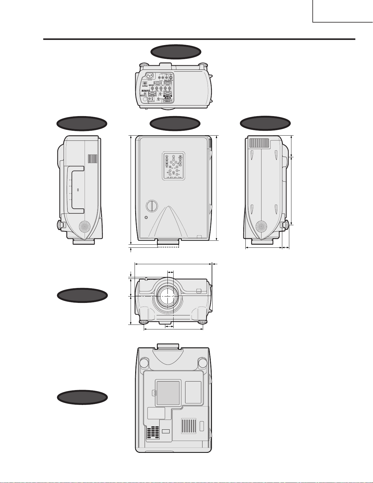
Dimensions
XG-P20XU
XG-P20XE
XG-P20XD
Rear View
Side View
Front View
(438)
64
/
15
17
/ 8 (3)
1
/ 32 (7)
9
(65)
16
/
9
2
12 9 /16 (319)
29
/32 (23)
(423)
32
/
21
16
9
/64 (3.5)
Side ViewTop View
6 3 /32 (155)
(79)11
6
/
1
3
(282.5)
25
/
3
1 3 /64 (26.5)
Bottom View
/ 64 (116.5)
37
4
3
/4 (248)
9
1
11
/32 (34)
Units: inches (mm)
11
Page 12
XG-P20XU
XG-P20XE
XG-P20XD
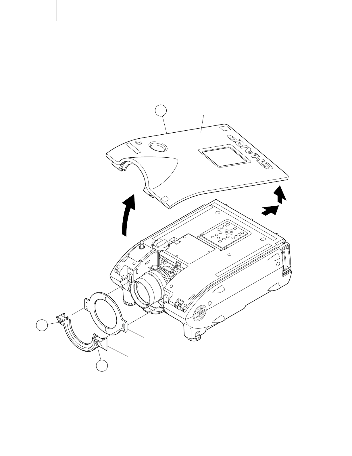
REMOVING OF MAJOR PARTS
1.Removing the top cover and lens cover.
1-1. Remove the two screws and detach the lens cover.
1-2. Hold the lens top cover and tilt it up until its back end alone stays hooked. Then slide and detach the top cover.
Detach the lens shutter.
(When attaching the lens shutter back in position, match the left (L) and right (R) markings.)
2
Top Cover
1
Lens Shutter
Lens Cover
1
12
Page 13
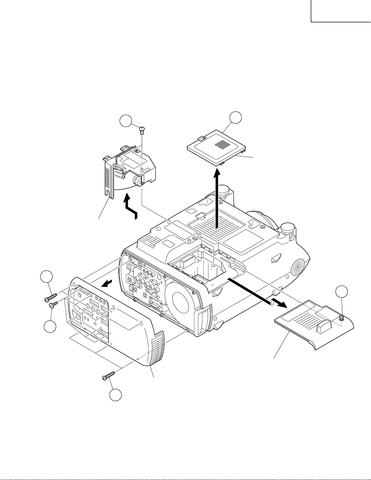
2.Removing the Intake cover and lamp unit.
2-1. Detach the intake cover.
2-2. Loosen the screw and slide the lamp cover out of position.
2-3. Remove the three screws and lift the lamp unit out of position.
3.Removing the rear body.
3-1. Remove the six screws off the terminal board at the back.
3-2. Remove the six screws and detach the rear body.
XG-P20XU
XG-P20XE
XG-P20XD
3-2
Lamp Unit
2-3
2-1
Intake Cover
2-2
3-1
Lamp Cover
Rear Body
3-2
13
Page 14
XG-P20XU
XG-P20XE
XG-P20XD
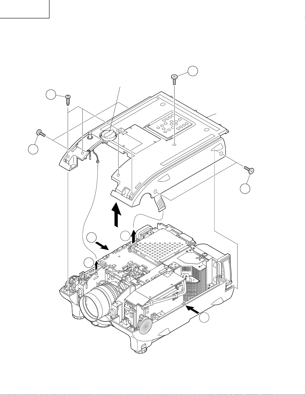
4.Removing the top panel.
4-1. Remove the five screws.
4-2. Remove the four screws.
4-3. Press on both sides of the set and undo the hooks. Lift the top body with lens shift knob and disconnect the
two connectors.
4-1
Lens Shift Knob
4-2
Top Body
4-1
4-3
4-3
4-1
4-3
4-3
14
Page 15
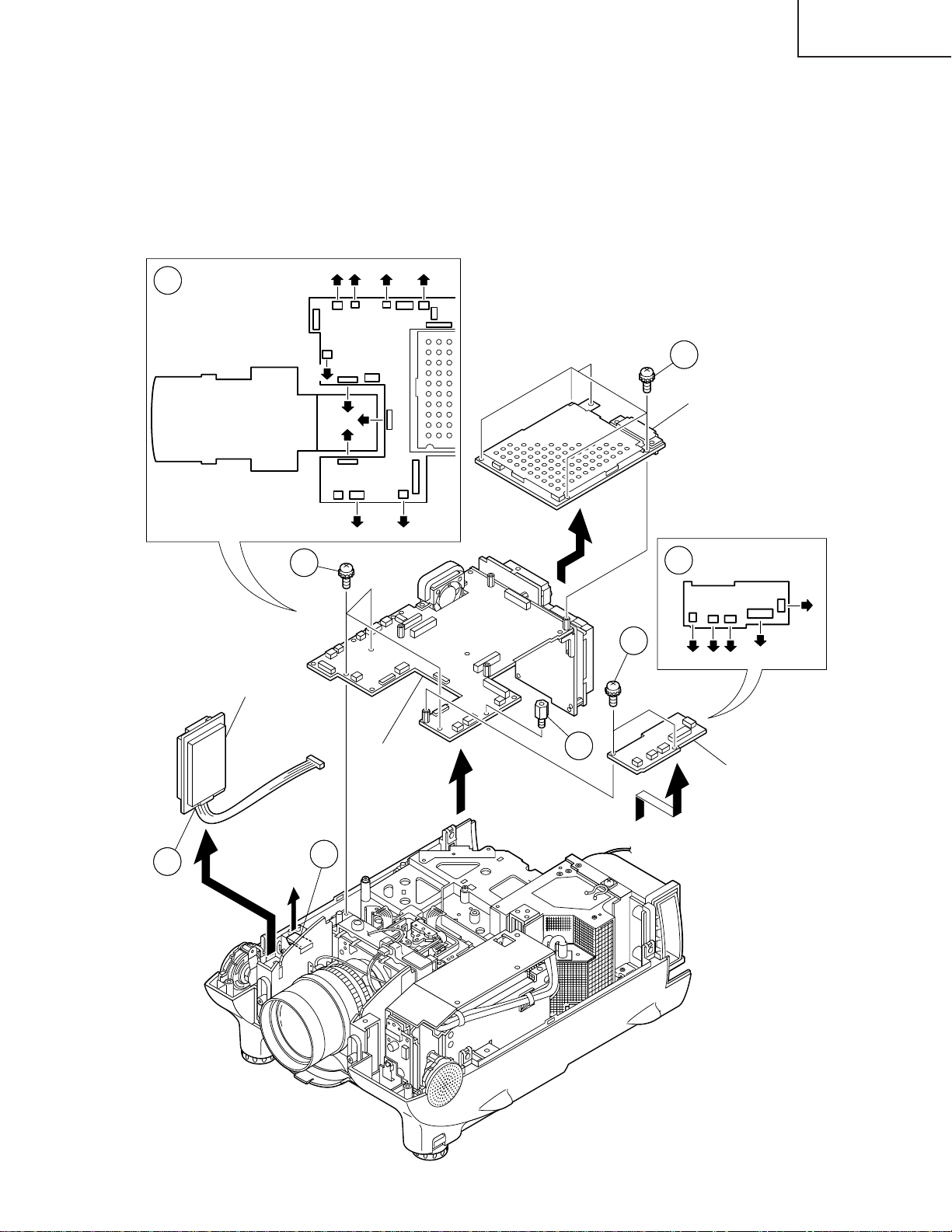
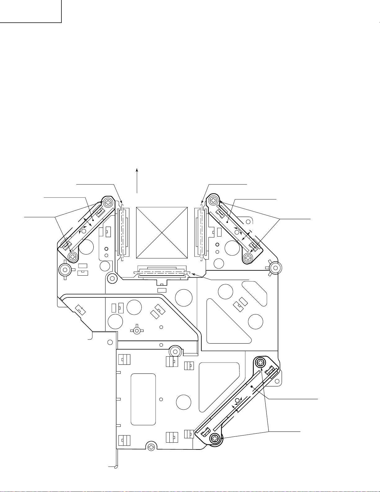
5.Removing the PWB unit.
5-1. Undo the top hooks and detach the GYRO PWB.
5-2. Disconnect the connectors from the GYRO PWB.
5-3. Remove the five screws and detach the PC I/F unit.
5-4. Disconnect the five connectors.
5-5. Remove the two screws and detach the output sub-PWB.
5-6. Disconnect the twelve connectors.
5-7. Take out the hexagonal supports.
5-8. Remove the three screws and detach the output/input PWB assembly.
(FF)(FD)(LF)(F)
5-6
(AZ)
XG-P20XU
XG-P20XE
XG-P20XD
5-3
GYRO PWB
5-8
(RP)
(BP)
(SO) (Q)
(GP)
Output/Input
PWB Ass'y
5-7
5-5
PC I/F Unit
5-4
(FE)
(EA)
(D)(FR)
Output Sub PWB
(GP)
5-2
5-1
15
Page 16
XG-P20XU
XG-P20XE
XG-P20XD
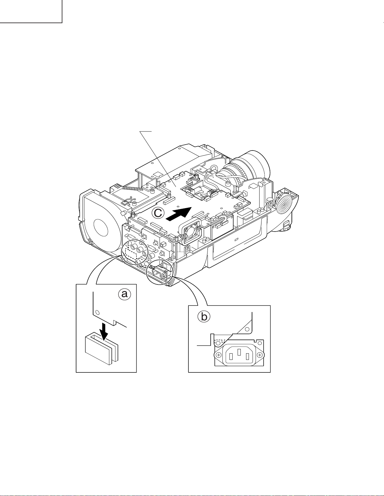
Reassembling precautions
5-9. Fit part a of the input PWB to the slit of the bottom cover.
5-10.Align the input PWB’s shield with the top of the AC inlet shield (b).
5-11.Before tightening up the screws (5-7) as well as the screws and hex nuts (5-8), move the PWB unit forward
enough (c).
PWB Unit Ass'y
16
Page 17
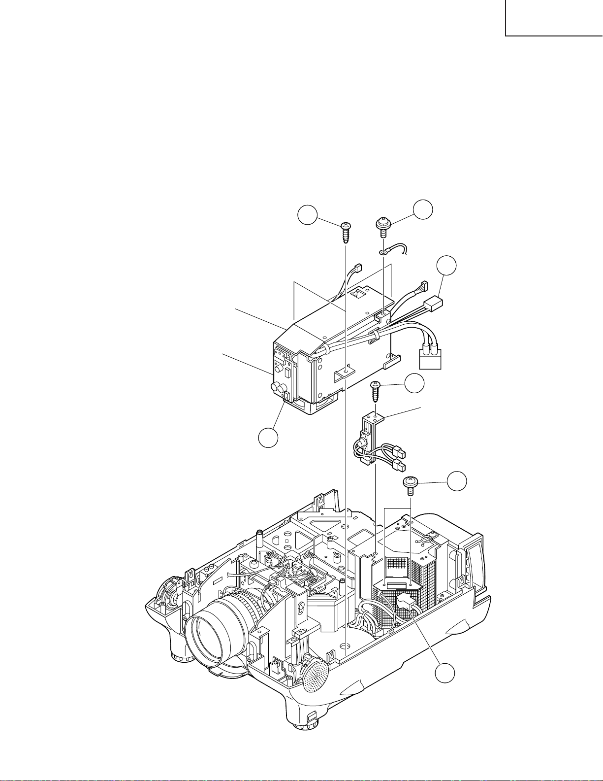
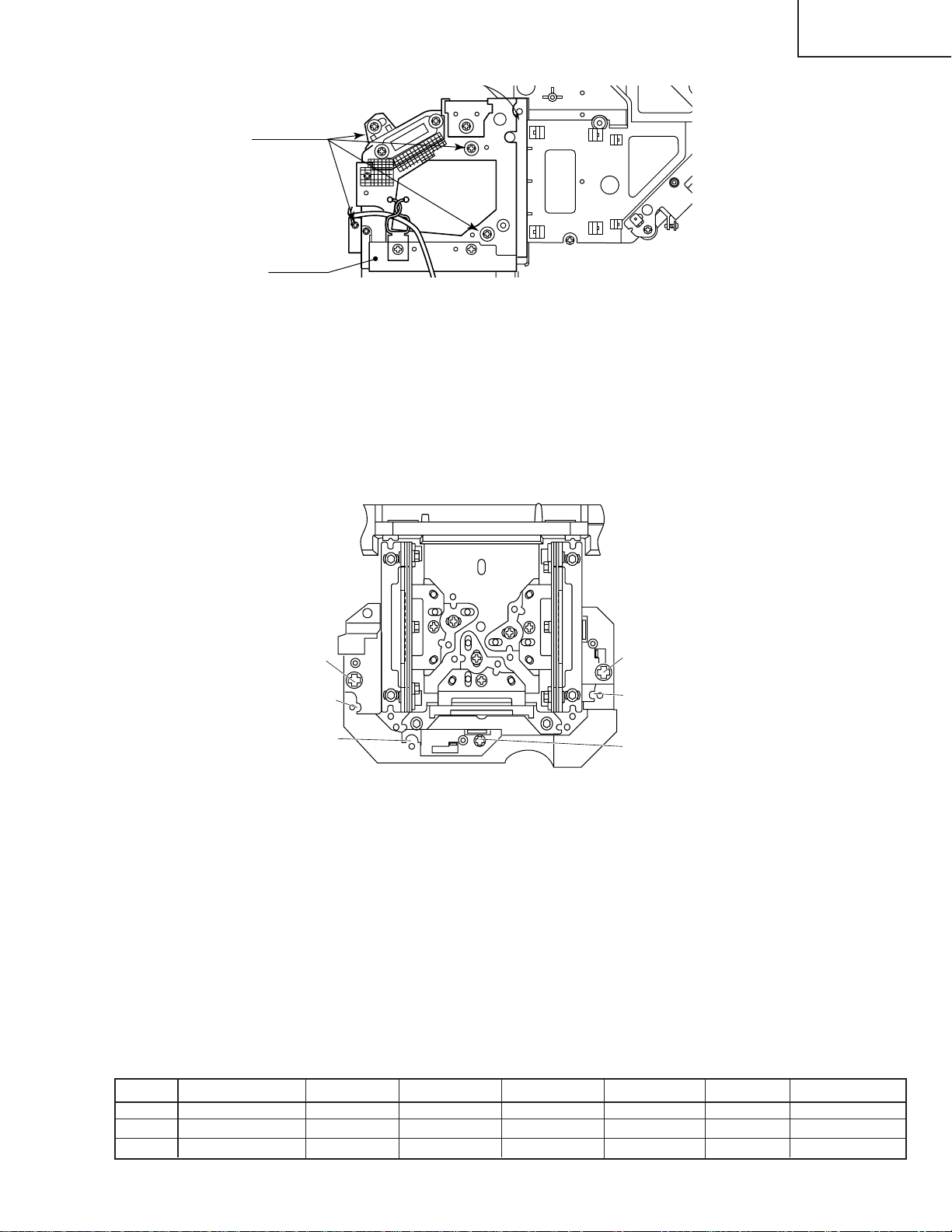
6.Removing the power / ballast / sound-out / bimetal unit assembly.
6-1. Remove the screw and disconnect the grounding wire from the shield case of the power/ballast unit.
6-2. Disconnect the connectors from the sound out PWB.
6-3. Take out the bimetal socket.
6-4. Remove the two screws and detach the lamp socket.
6-5. Remove the three screws and detach the power unit.
6-6. Remove the screw and slide the bimetal assembly upward out of position.
XG-P20XU
XG-P20XE
XG-P20XD
Power/Ballast Unit
Sound Out PWB
6-2
6-5
6-1
6-3
6-6
Bimetal Ass'y
6-4
17
6-3
Page 18

XG-P20XU
XG-P20XE
XG-P20XD
7.Removing the optical mechanism unit
7-1. Remove the two screws off the optical mechanism intake fan.
7-2. Remove the eight screws and take out the optical mechanism unit.
7-3. Remove the screw and disconnect the grounding wire.
7-4. Disconnect the connector and detach the AC inlet unit.
7-2
7-2
Optical Mechanism Unit
7-2
7-2
7-1
7-3
7-4
AC Inlet Unit
18
Page 19
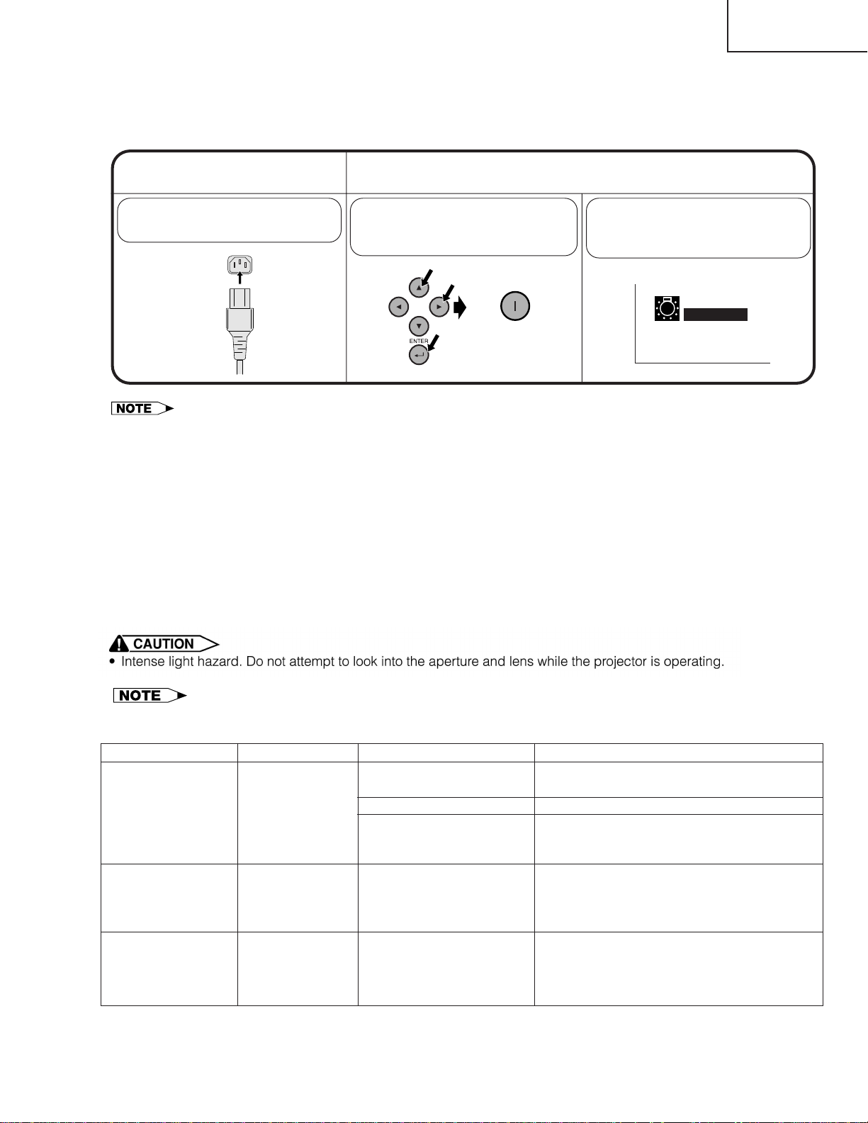
Resetting the TOTAL LAMP TIMER
Resetting the lamp timer
XG-P20XU
XG-P20XE
XG-P20XD
Connect the power
1
cord.
Plug the power cord into the AC
socket of the projector.
•Reset the lamp timer only after replacing the lamp.
Reset the lamp timer.
2
While pressing ",| and
ENTER on the projector,press
POWER ON on the projector.
ON
“LAMP 0000H ” is displayed,
indicating that the lamp timer is
reset.
LAMP 0000H
• As the usage environment can vary significantly, the projector lamp may not operate for 1,500 hours.
Maintenance Indicator
TEMPERATURE
WARNING indicator
LAMP REPLACEMENT indicator
POWER indicator
The internal
temperature is
abnormally high.
The lamp does
not light up.
The POWER
indicator flashes
in red when the
projector is on.
Condition
· Blocked air intake.
· Clogged air filter.
· Cooling fan breakdown.
· Internal circuit failure.
· Burnt-out lamp.
· Lamp circuit failure.
· The bottom filter cover is
open.
Problem
Possible Solution
· Relocate the projector to an area with
proper ventilation.
· Clean the filter.
· Take the projector to your nearest Authorized Sharp Industrial LCD Products
Dealer or Service Center for repair.
· Carefully replace the lamp.
· Take the projector to your nearest Authorized Sharp Industrial LCD Products
Dealer or Service Center for repair.
· Securely install the bottom filter cover.
19
Page 20

XG-P20XU
XG-P20XE
XG-P20XD
THE OPTICAL UNIT OUTLINE
Layout of the optical system
Note: Layout for positioning the optical system.
Projection Lens
1/2λ plate
Sapphire glass
Polarizing plate
Incident polarizing plate B
1/2λ plate + polarizing plate
Sapphire glass
Polarizing plate
Incident polarizing plate R
Dichroic coating
(B transmission)
M6
BLUE
AL-coated mirror B
G03 L2
Relay lens 1
Relay lens 2
G02 L2
AL-coated mirror B
M4
AL-deposited face
B-LCD
Cross dichroic prism
G-LCD
Incident polarizing plate G
Marking
G01
Relay lens 1
UV-absorption-filter
Condenser lens G
GREEN
BLUE
G reflector
* M3
Dichroic coating
R-LCD
1/2λ plate
Sapphire glass
Polarizing plate
Dichroic coating
(R, G transmission)
Dichroic coating
PBS(polarization
beam splitter)
(R transmission)
Condenser lens R
Marking
AL-coated mirror R
M5
AL-deposited face
RED
(R reflection)
M2
B/G reflector
* The M3 mirrors have a coating
wedge (for different film thickness). Set up these mirrors, with
their markings positioned as
shown above, so that their
coated faces and both sides be
in the correct directions.
UHP lamp
(Light source)
L1
AL-deposited
face
PBS aperture
Fly-eye lens (outgoing light)
UV-IR coating
Fly-eye lens (incoming light)
20
M1
AL-coated mirror W
Page 21

XG-P20XU
XG-P20XE
XG-P20XD
CONVERGENCE AND FOCUS ADJUSTMENT
» Start the convergence and focus adjustments with the top cabinet and the LCD cover
removed but the power on. Use the remote control to adjust the image. Take the following procedures.
1. Focusing the projection lens
(A) Replacing all the 3 LCD panels
1. Before replacing all the 3 LCD panels, project an image on the screen and bring it into focus.
2. Replace the panels with new ones. But until the focus has been completely readjusted, be careful not to
change the distance between the set and the screen, nor to move the projection lens focus and zoom
rings.
If the focus is readjusted with a different positional relation, the relation between the projection distance
and the screen size is affected. In other words, a short-distance image (40 WIDE, for example) may get
out of the focus range, or a long-distance image (300 WIDE, for example) may come out of focus.
(B) Replacing 1 or 2 of the 3 LCD panels
1. In adjusting the focus after replacement of one or two LCD panels, project an image on the screen and turn
the projection lens focus ring to get the non-replaced LCD panel into focus.
2. But until the focus has been completely adjusted for the new LCD panels, be careful not to change the
distance between the set and the screen, nor to move the projection lens focus and zoom rings.
(If the distance has been changed or the projection lens readjusted, repeat the above steps 1 and 2.)
2. Adjusting the G-LCD panel
(A) Focus adjustment. (Make this adjustment on the white-only screen.)
1. Right-and-left focus adjustment (θY direction) .
Loosen the lock screws "b" and "c" and insert the eccentric screwdriver into the notch and hole "b". Turn
the screwdriver until the right and left halves on the screen get into focus.
First get the right and left halves in balance. Then improve the accuracy while making the adjustment 2
below.
2. Top-center-bottom focus adjustment (θX and Z directions).
Loosen the lock screws "a" and "c" and insert the eccentric screwdriver into the notch and hole "a" or "c".
Turn the screwdriver until the top, center and bottom on the screen get into focus. In adjusting this top-tobottom focus, temporarily tighten the lock screw "b" to fix the θY direction adjustment.
3. Repeat the above steps 1 and 2 to finely adjust the focus. Finally tighten up all the lock screws.
Notes :
1 Carefully proceed with the focus adjustment because the adjusting directions are correlated.
2 In adjusting the convergence and focus, do not move the projection lens zoom and focus rings until the end
of all the adjustments.
(B) Convergence adjustment
» The G-LCD panel has no convergence adjustment mechanism. Use this panel as convergence adjustment
reference.
3. B-LCD panel adjustment (the same for the R-LCD panel)
(A) Focus adjustment
» T ake the same procedure as for the G-LCD panel focus adjustment. Note that the adjustment range is small
in the Z direction. If the convergence is quite different between the B-LCD and G-LCD panels, roughly adjust
the convergence first and then the focus.
(B) Convergence adjustment
» Use a crosshatch pattern signal for this adjustment.
Make the adjustment just for the G-color and the relevant color.
(1) Loosen the convergence lock screw "d".
(2) With the G-LCD panel’s screen center as reference, adjust the B-LCD panel in the X, Y and θZ directions.
(3) Finally tighten up the convergence lock screw "d".
21
Page 22
XG-P20XU
XG-P20XE
XG-P20XD
Notes :
1 The eccentric cam is used for convergence adjustment. This means that the cam’s turning and the linear
movement are not always uniform.
2 This model is not equipped with the LCD image adjustment mechanism. This is because the dichroic prism
is used for image formation. When the LCD panels all get into the best focus, the images are almost
completely converged.
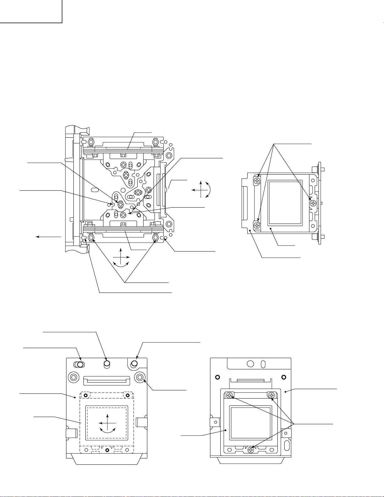
Convergence and Focus Adjustments Mechanism
TOP VIEW
Lock screw "a"
Notch and hole "a"
(Use an eccentric
screwdriver.)
FRONT
R-LCD
B-LCD
Z
X
θY
Lock screws "c"
Notch and hole "c"
(Use an eccentric screwdriver.)
Notch and hole "b"
(Use an eccentric
screwdriver.)
G-LCD
Lock screw "b"
(θY direction)
Notch and
hole "c"
(Use on eccentric
screwdriver.)
X
Z
SIDE VIEW
G-LCD panel
mounting screws
θY
G-LCD
G adjusting plate
SIDE VIEW (from inside)
Eccentric cam
(X direction adjustment)
Eccentric cam
(Y direction adjustment)
R¥B adjusting plate
R¥B-LCD
SIDE VIEW (from outside)
Eccentric cam
(θZ direction adjustment)
Lock screw "d"
(convergence
adjustment)
Y
X
θZ
R¥B-LCD
R¥B adjusting plate
R¥B-LCD panel
mounting screws
22
Page 23
Convergence and Focus Adjustments at a Glance
2
5
16
R2
50
CUT
Adjustment directions
Adjustment Direction Definition Direction of LCD panel
X direction LCD right and left
Convergence Y direction LCD top and bottom
θZ direction Rotation around Z axis LCD turning axis
Z direction LCD optical axis
Focus θX direction Rotation around X axis LCD top-to-bottom flapping
θY direction Rotation around Y axis LCD right-to-left flapping
Convergence and Focus Adjustment for the Optical Mechanism
XG-P20XU
XG-P20XE
XG-P20XD
Color Adjustment Direction
X direction ±0.8mm Eccentric cam Eccentric cam adjusting wrench d Hex wrench
Convergence Y direction ±0.8mm Eccentric cam Eccentric cam adjusting wrench d Hex wrench
R/B θZ direction ±1° Eccentric cam Eccentric cam adjusting wrench d Hex wrench
colors Z direction ±0.8mm
Focus θX direction ±1°
θY direction ±1°
Z direction ±0.2mm
G color Focus θX direction ±1° Same as for R and B colors
θY direction ±1°
Movement
Position Adjusting tool
Notch and hole "a" & "c"
Notch and hole "a" & "c"
Notch and hole "b" & "c"
Eccentric screwdriver, a, c
Lock screw
a, c
b, c
Tightening tool
Phillips
screwdriver,
*Hex wrench
Focus Adjustments the Other Way
Lock screw Position Related direction
a Notch and hole "a" Z and θX directions
b Notch and hole "b" θY direction
c Notch and hole "c" Z, θX and θY directions
Convergence and Focus Adjusting and Tightening Tools
Tool Specific or General Tool code Configuration
Eccentric cam Specific 9DASPN-XGNV1U
adjusting wrench
80
Eccentric screwdriver Specific 9EQDRiVER-NV1A
100
Hex wrench General (redesigned) 9EQLNC-XGNV1U
Phillips screwdriver General — For M2.6 pan-head machine screw
*Hex wrench General —
23
Preferably use a 70 mm or longer
screwdriver (with a handle).
Page 24
XG-P20XU
XG-P20XE
XG-P20XD
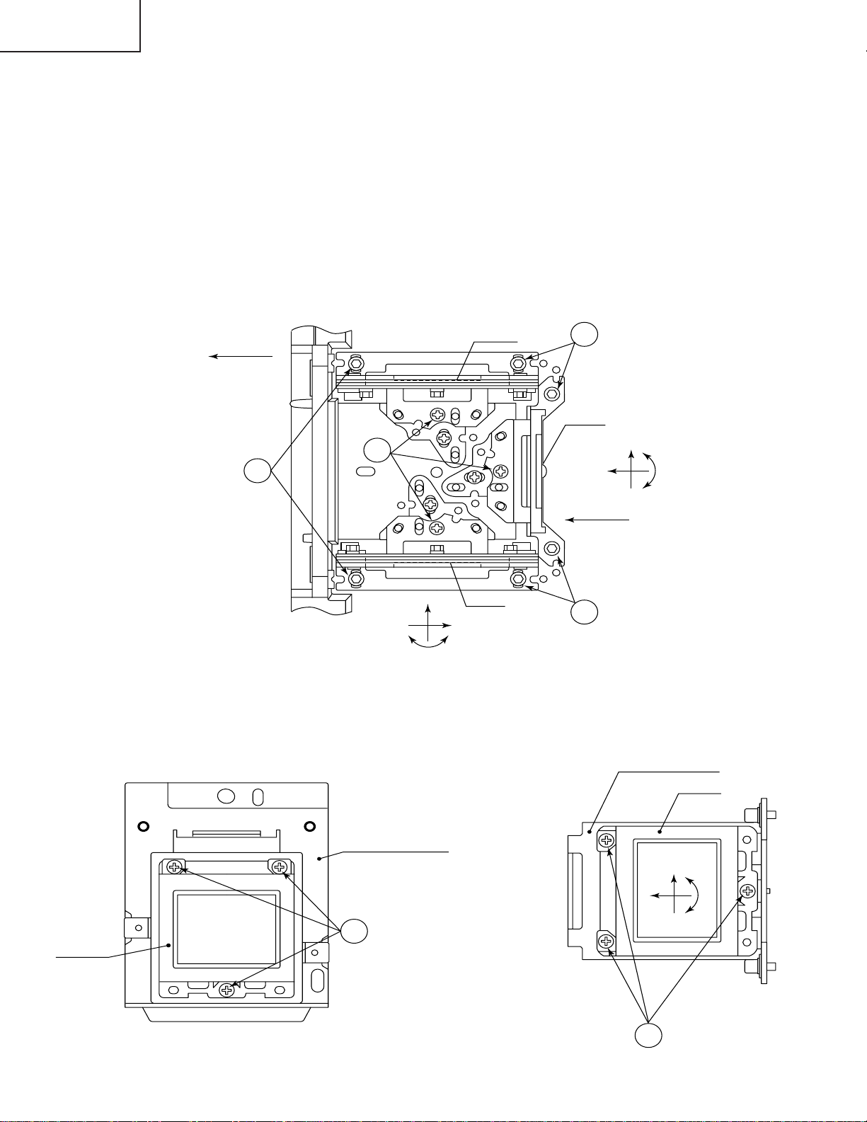
Replacing the G-LCD and B-LCD panels
With the top cabinet removed
(1)Disconnect the LCD flat cable from the output PWB connector.
(2)Remove the lock screws "b" and "c". Detach the R/B adjusting plate or the G adjusting plate together with the LCD
panel.
(3)Separate the LCD panel from the adjusting plate.
(4)Mount a new LCD panel in the reverse order of the above steps (1), (2) and (3).
~ Readjust the convergence and focus. Note that the G LCD panel needs no convergence adjustment and has
a small adjustment range in the Z direction.
TOP VIEW
Lock screws "c"
R-LCD
FRONT
2
SIDE VIEW
2
Lock
screws "c"
Lock
screws "b"
2
G-LCD
X
θY
Z
~
θY
X
B-LCD
2
Lock screws "c"
Z
SIDE VIEW
G adjusting plate
G-LCD
B-LCD
B adjusting plate
3
B-LCD panel
mounting screws
24
X
Y
G-LCD panel
3
mounting screws
θZ
Page 25
XG-P20XU
XG-P20XE
XG-P20XD
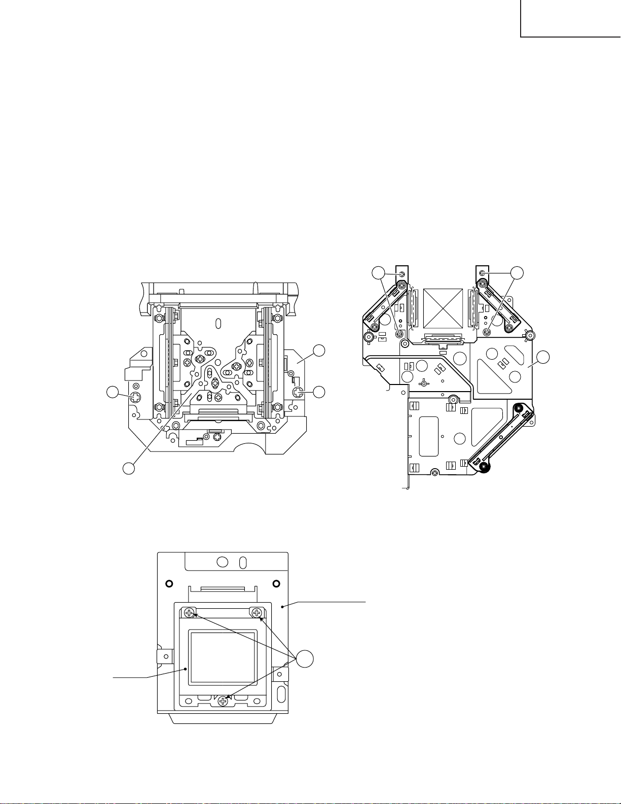
Replacing the R-LCD panel
(1)Disconnect the LCD flat cable from the output PWB connector.
<Figure 1>
(2)Remove the two screws "A".
(3)Lift and detach the plate "B" together with the incident light deflection plate.
<Figure 2>
(4)Remove the four screws "C" and separate the units D and E from each other.
(5)Take the R-LCD panel out of the adjusting plate.
(6)Place and fix a new R-LCD panel in the reverse steps.
(7)Adjust the deflection plate. (See page 26).
(8)Adjust the focus and convergence. (See page 21.)
~ Readjust the convergence and focus. Note that the G LCD panel needs no convergence adjustment and has
a small adjustment range in the Z direction.
C
B
A
D
A
C
E
Fig.1
Fig.2
SIDE VIEW
R-LCD
R adjusting plate
4
R-LCD panel
mounting screws
25
Page 26
XG-P20XU
XG-P20XE
XG-P20XD
Adjusting the optical axis of the mirrors (M1, M5 and M6)
The optical axis must be readjusted if an eclipse happens with the R. G or B mirrors. Generally speaking,
this adjustment is needed when any of the internal optical components has been replaced.
Adjustment procedure required when any of the panels has been replaced or the convergence has been
adjusted
(1)Disconnect the flat cables of all the LCD panels.
(2)Let the lamp light up.
(3)To adjust the G mirror, shield the R and B mirrors with shielding plates (You can use a business card or the like to
block the light).
(4)Loosen the lock screw of the M1 adjust lever.
(5)Looking at the G image on the screen, turn or slide the M1 adjust lever until the eclipse on the screen disappears.
Tighten up the screw.
(6)To adjust the R mirror, shield the G and B mirrors and adjust the M5 adjust lever. For the B mirror , shield the R and
G mirrors and adjust the M6 adjust lever.
(Take the same steps 4 and 5 above.)
(7)Remove all the shielding plates to have a white image.
Make sure there is no eclipse.
M6
Lock screws
Shielding plate B
adjust lever
slide
turn
FRONT
Shielding plate R
M5
Shielding plate G
adjust lever
Lock screws
turn
slide
26
slide
turn
M1
adjust lever
Lock screws
Page 27
XG-P20XU
XG-P20XE
XG-P20XD
Adjusting the lamp duct.
Lock screws
Lamp duct
Adjustment procedure reguired when the lamp has been replaced and you can see ununifomity. (Case of
Right and Left have ununifomity on the screen)
(1) Let the lamp light up.
(2) Receive the white pattern signal at 100%.
(3) Loosen the four lock screws from the lamp duct.
(4) Looking at the white image on the screen, turn the lamp duct until the uniformity comes to best point on the screen.
(5) Tighten the lock screws of the lamp duct. (Tighten torque is 10±2kg·cm)
Adjustment of incident polarizing plate.
Carry it out when removing polarizingplate.
Screw C
Notch & Hole C
Notch & Hole B
Screw A
Notch & Hole A
Screw B
(From the condition that the top cabinet opens.)
1.Remove screws, earth plate from the output PWB.
2.Extend each FFC cable of R, G, B (Using QCNW-4852CEZZ) and try so that it can move a PWB so that it can
see the part which adjusts polarizing plate from the top.
3.Turn on the power, and indicate a black screen on the screen.
<Adjusting the G-LCD incident polarizing plate.>
4.Move an output PWB so that you can see screw B and notch & hole B.
5.Put an eccentric screwdriver (9EQDRIVER-NV1A) in notch & hole B, and loosen screw B.
(Loosen it too much, and be careful that the screw doesn't come off.)
6.Adjust with the eccentric screwdriver in the place where a brightness is the lowest, and tighten screw B, and fix it
with seeing a black screen.
Adjust it with screw A and notch & hole A when adjusting incident polarizing plate of R-LCD.
Adjust it with screw C and notch & hole C when adjusting incident polarizing plate of B-LCD.
❈Adjust it in the turn of Green, Red, Blue with 3 place of RGB as well when adjusting it.
❈Be careful not to make it short-circuit when moving an output PWB.
Color adjustment
Red
Green
Blue
polarizing plate adjustment
polarizing plate adjustment
polarizing plate adjustment
Adjustment directionAmount of adjustment. Adjustment place form
θ direction ±1° Notch & Hole A
θ direction ±1° Notch & Hole B
θ direction ±1° Notch & Hole C
Ajdustment jig Fixing screw Fixed screw tool.
eccentric screwdriver
eccentric screwdriver
eccentric screwdriver
A Phillips screwdriver
B Phillips screwdriver
C Phillips screwdriver
27
Page 28
XG-P20XU
XG-P20XE
XG-P20XD
ELECTRICAL ADJUSTMENT
Hook up a signal generator, or a DOSV or Mac personal computer to the projector in order to feed the
signals specified in the Adjusting conditions.
No. Adjusting point Adjusting conditions Adjusting procedure
1 EEPROM
initialization
1. Turn on the power (make
sure the lamp lights up) and
warm up the unit for 15 minutes.
» Make the following settings:
Press S2601 to call up the process mode and
execute S2 and S4 in the SSS menu. Now the
system, with the PC board not included, is initialized. Do not execute S1 because otherwise the
PC board will be initialized.
To adjust the PC board, follow the instruction in
"Adjusting the PC Interface". (See page 34)
2 R drive 1. Make the following choice.
Group : A/D
2. Feed the 100% red-only signal. Make the following
choice.
Group : A/D
Subject : R-D
3 B drive 1. Feed the 100% blue-only
signal. Make the following
choice.
Group : A/D
Subject : B-D
4 G drive 1. Feed the 100% green-only
signal. Make the following
choice.
Group : A/D
Subject : G-D
» Using the control switches or the remote controller
buttons, adjust the data so that the signal becomes bit-less (noise).
» Using the control switches or the remote controller
buttons, adjust the data so that the signal becomes bit-less (noise).
» Using the control switches or the remote controller
buttons, adjust the data so that the signal becomes bit-less (noise).
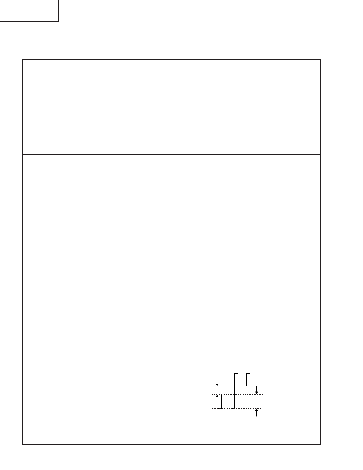
5 RGB 1 system
black level
signal amplitude
(odd-numbered)
1. Make the following choice:
Group : OUTPUT 1
Subject : G1-BLK
G1-GAIN
For green, choose the sub-
jects R1-BLK and R1-
GAIN.
For blue, choose the subjects B1-BLK and B1-GAIN.
2. Connect the oscilloscope to
TP1101 for red.
TP1201 for green
TP1301 for blue
» Choose the subject G1-GAIN and adjust the sig-
nal amplitude to 3.9 ±0.05 Vp-p using the control
switches or the remote controller buttons.
» Next, choose the subject G-BLK and adjust the
white peak level to 2.0Vp-p ±0.1V.
2.0Vp-p
» Make the same adjustments for green and blue.
3.9Vp-p
28
Page 29
No. Adjusting point Adjusting conditions Adjusting procedure
XG-P20XU
XG-P20XE
XG-P20XD
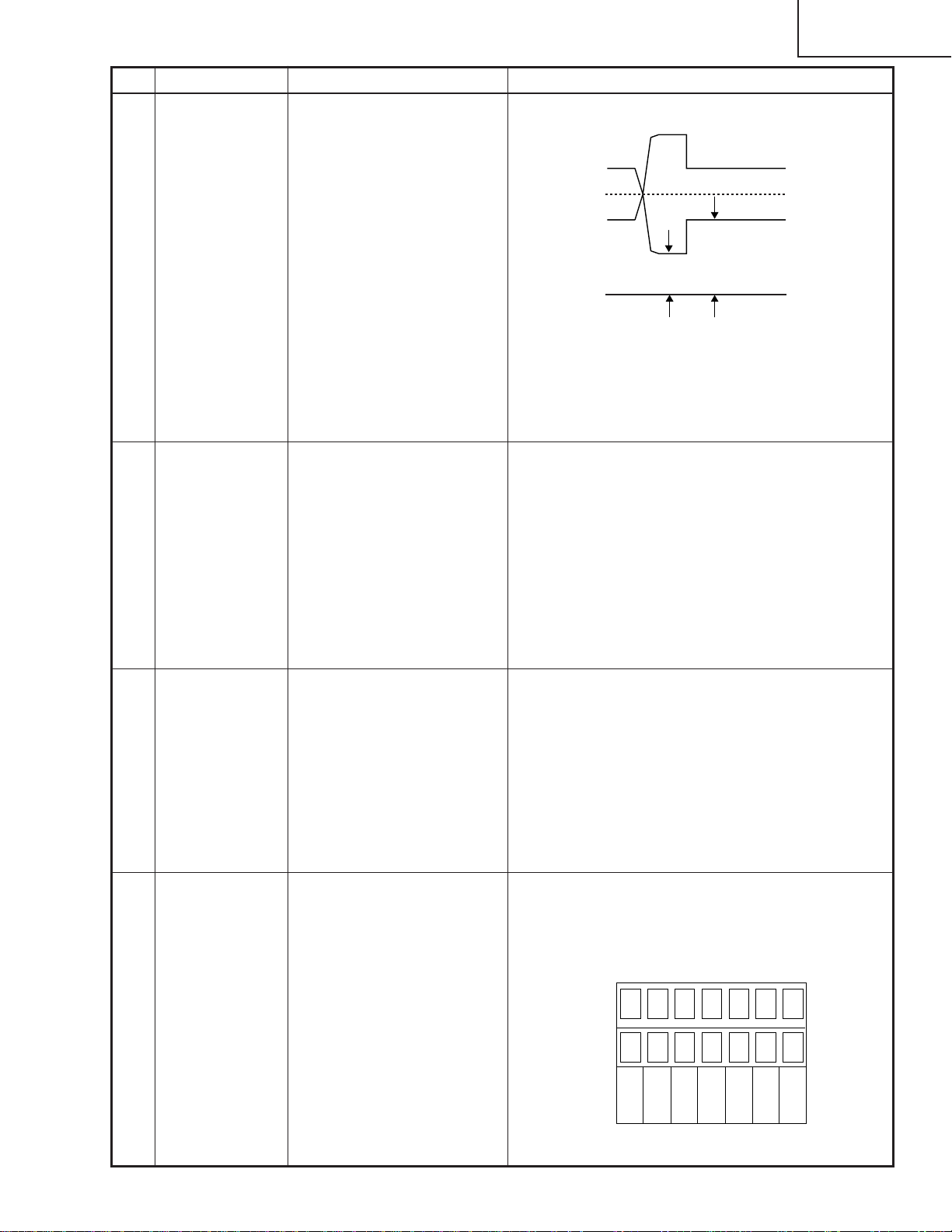
6 P SIGNAL 1. Connect the oscilloscope to
TP1102 for red.
2. Make the following choice:
Group : OUTPUT 2
Subject : PSIG-H
: PSIG-L
7 Sample-and-
hold pulse
phase
RCK-PHASE
GCK-PHASE
BCK-PHASE
1. Feed the XGA mode 75-Hz
black signal.
2. Make the following choice:
Group : OUTPUT 3
Subject : SH-PHASE
(Have the standard level at
8.)
Fix the GCK-PHASE settings all to 8.
» Adjust the PSIG waveform to the one shown below.
PSIG
2.5V DC 5.0V DC
(Adjust with PSIG-L.)(Adjust with PSIG-H.)
GND
» For the green and blue colors, make sure their wave-
forms are similar to that of the red color.
» Using the control switches or the remote controller
buttons, make sure that the “OUTPUT 3” characters are not blurry and there is no ghost image. If
such blur or ghost occurs, finely adjust the setting
in the range of 7~9.
8 RGB counter-
voltage
adjustment
9 RGB gradation
regeneration
adjustment
1. Feed the black-and-red
(25%) stripe signal (XGA).
2. Make the following choice:
Group : OUTPUT 3
Subject : RC (R)
: BC (B)
: GC (G)
1. Feed the INFO COM. gray
scale and color bar pattern.
2. Make the following choice:
Group : OUTPUT 1
Subject : G1-BLK
» Using the control switches or the remote controller
buttons, adjust the data in order to minimize the
flicker.
» Make the same adjustment for BC (B) and GC (G).
» See if the image is equally adjusted at the center
and both sides of the screen. If not, readjust the
setting to have the image equal at right and left.
» Make sure that scale (white side) to No.251 and
scale (black side) to No.8 can be seen.
» If white scale can't be seen properly, readjust with
G1-BLK.
4812
249 251
29
Page 30
XG-P20XU
2.2Vp-p
XG-P20XE
XG-P20XD
No. Adjusting point Adjusting conditions Adjusting procedure
10 RGB white
balance
1. Feed the 32-step gray scale
signal (XGA 60Hz).
Group : OUTPUT 1
Subject : R1-BLK (R)
R1-GAIN(R)
» Adjust the R1-BLK and B1-BLK data for the black
balance on the gray scale. Then adjust the R1GAIN and B1-GAIN data for the center-to-white
balance on the gray scale.
(Adjust to the best point.)
B1-BLK (B)
B1-GAIN(B)
11 Horizontal
center
12 Video
brightness
adjustment
13 Video picture
adjustment
1. Feed the NTSC monoscope pattern signal.
2. Group : VIDEO 1
Subject : NTSC-H
1. Feed the baseband (0 step
gray scale :0% Black to
100% White) signal.
Group : VIDEO 1
Subject : BRIGHT
2. Press the control switch or
the remote control’s mute
button (to set the gamma
correction to the process
setting).
1. Feed the split color bar signal.
Group : VIDEO 1
Subject : PICTURE
» Using the control switches or the remote controller
buttons, adjust the data to have the same
overscan.
» Using the control switches or the remote controller
buttons, adjust the setting until the black signal (0%)
becomes bit-less.
» Using the control switches or the remote controller
buttons, adjust the white to white (100%) level
difference to 2.2 ± 0.05 Vp-p.
14 Tint
2. Connect the oscilloscope
between pin TP1201and
GND.
1. Feed the split color bar signal.
Group : VIDEO 1
Subject : TINT
2. Connect the oscilloscope to
TP1301.
» Using the control switches or the remote controller
buttons. Adjust the setting so that the points indicated in the waveform figure are at the same level.
SAME LEVEL
30
Page 31

No. Adjusting point Adjusting conditions Adjusting procedure
100% White Red
XG-P20XU
XG-P20XE
XG-P20XD
15 NTSC color
saturation level
16 PAL color
saturation level
1. Feed the split color bar signal.
Group : VIDEO 1
Subject : N-COLOR
2. Connect the oscilloscope to
TP1 101.
1. Feed the PAL color bar signal.
Group : VIDEO 1
Subject : P-COLOR
2. Connect the oscilloscope to
TP1 101.
» Using the control switches or the remote controller
buttons, adjust the difference between the 100%
white portion and the red portion to 0.25 ±0.02 Vp-p.
(same as 100% white)
» Using the control switches or the remote controller
buttons, adjust the difference between the 100%
white portion and the red portion to 0.3 ±0.02 Vp-p.
100% White Red
17 SECAM color
saturation level
18 Video white
balance
19 DVD Contrast 1. Feed the color bar signal of
1. Feed the SECAM color bar
signal.
Group : VIDEO 1
Subject : S-COLOR
2. Connect the oscilloscope to
TP1 101.
1. Feed the NTSC mono-
scope pattern signal
Group : VIDEO 2
Subject : R1-BLK
B1-BLK
the 480I component signal
to the BNC G(Y) input terminal.
» Using the control switches or the remote controller
buttons, adjust the data to have a level difference
of 0.3 ±0.02 Vp-p between the 100% white portion
and the red portion.
100% White Red
» Using the control switches or the remote controller
buttons, adjust so that the entire screen looks
evenly colorless.
» Using the control switches or the remote controller
buttons, adjust the white to white (100%) level
difference to 2.2 ± 0.05v p-p.
2. Select the following subject.
Group : DVD
Subject : CONTRAST
2.2Vp-p
31
Page 32

XG-P20XU
XG-P20XE
XG-P20XD
No. Adjusting point Adjusting conditions Adjusting procedure
20 DVD Brighthess 1. Feed the color bar signal of
the 480I component signal
to the BNC G(Y) input terminal.
2. Select the following subject.
Group : DVD
Subject : CONTRAST
21 DVD Tint 1. Feed the color bar signal of
the 480I component signal
to the BNC Y, Pb and Pr input terminals. Feed the
sync signal only for the Y
signal.
2. Select the following subject.
Group : DVD
Subject : TINT
3. Connect the oscilloscope to
TP1301.
» Using the control switches or the remote controller
buttons, adjust the setting until the black signal(0%) becomes bit-less.
» Using the control switches or the remote controller
buttons. Adjust the setting so that the points indicated in the waveform figure are at the same level.
SAME LEVEL
22 DVD Color 1. Feed the color bar signal of
the 480I component signal
to the BNC G(Y) input terminal.
2. Select the following subject.
Group : DVD
Subject : COLOR
3. Connect the oscilloscope to
TP1 101.
23 DVD White
balance
adjuustment
1. Feed the NTSC monoscope signal to G(Y) input
terminal of the BNC terminal.
2. Select the following subject.
Group : DVD
Subject : R1-BLK
B1-BLK
24 Checking and
readjustment of
white balance
1.The adjustment condition of
each item is as mentioned
in the following.
RGB input:Refer to No.11
VIDEO input:Refer to No.19
DVD input:Refer to No.23
» Adjust the level difference between the 100% white
and red portions to 0.3 ±0.02 Vp-p.
100% White Red
» Adjust so that a white balance may become the best
condition by using the control switch or buttons of
the R/C.
» Make sure that a white balance is the best condi-
tion.
32
Page 33

No. Adjusting point Adjusting conditions Adjusting procedure
XG-P20XU
XG-P20XE
XG-P20XD
25 Color system
performance
check
26 Video system
performance
check
27 Audio system
performance
check
28 RGB
performance
check
29 Off-timer
performance
check
30 Thermistor
performance
check
1. Receive the color bar signal.
1. Receive the monoscope
pattern signal.
» In the process mode and select L1. Check the color
and tint.
» In the process mode and select L2. Check the pic-
ture, brightness and sharpness.
» In the process mode nad select L3. Check the bass,
treble and balance.
1. Receive the RGB signal. » In the process mode and select L4. Check the pic-
ture, brightness, red, blue, clock, phase, horizontal
position, and vertical position.
» In the process mode and select OFF . Make sure that
the off-timer starts with “5” (minutes), counts down
each minute in 1 second, and turns off the set at “0”.
1. Heat the thermistor using a
» Make sure the “TEMP” is displayed.
dryer.
31 Automatic
synchronization
32 Keystone
correction
performance
check
1. Receive the PHASE check
pattern signal.
» Call the VGA/S-VGA/XGA mode and make sure
that the clock, phase, horizontal and vertical
positions can be automatically adjusted.
» Make sure the keystone correction functions well.
» Make the following settings.33 Factory settings
Process
adjustment
S4 "Factory setting 4" for XU
S3 "Factory setting 3" for XE/XD
Remote controller setting
33
Page 34

XG-P20XU
XG-P20XE
XG-P20XD
ADJUSTING THE PC INTERFACE (CPCi-0054CE01/02. PC I/F Unit)
1.The initialization of the set.
1) Press the S2601 switch to go to the process mode.
2) Perform S1 of the SSS menu. (S1 initializes only a PC I/F board. Don’t perform S2 because adjustment data
except for the PC board are initialized.
3) Make sure that version of the SPECIAL program (VER.XXX) of the menu is the latest.
2.Adjusting the level.
2-1. Setting the oscilloscope
Set the range to DC 1 V/div and 5µ/div.
2-2. Connecting the PC Interface
1) Connect the cable between the ANALOG OUTPUT (PC computer) and the DSUB connector (INPUT1 of the
proejctor).
2) Set the PC computer in the XGA mode (1024 x 768, 60 Hz, 32-step scale). Adjust the output amplitude to 700
mVp-p (terminated with 75 ohms) for the black-to-white portions.
3) Turn on the power.
2-3. Adjusting and checking the level
1) Press the S2601 switch to go to the process mode.
2) Set the SH-PHASE on the OUTPUT3 menu to 8. (Make the characters on screen clear and crisp.)
3) Adjust black level of red signal with R-BRIGHT of the A/D in a place to become bit less condition.
4) Adjust black level of blue signal with B-BRIGHT of the A/D in a place to become bit less condition.
5) Adjust black level of green signal with G-BRIGHT of the A/D in a place to become bit less condition.
2-4. Adjusting the DTV
1) Set the switch to the BNC input terminal of INPUT1
2) Set up a signal generator in 1080i 60Hz mode white signal.Output amplitude makes space between black - white
700mVp-p (75ohm terminated) .
3) Connect the analog output terminal of the signal generator and BNC connector (the INPUT1 terminal of projector)
with the cable.
4) Make G-BRIGHT of DTV the numerical value which is the same as G-BRIGHT of A/D.
5) Set up the level of the signal output in 53%, and adjust with CB-OFFSET of the DTV in a place to become bit less
condition.
6) Set up the level of the signal output in 53%, and adjust with CR-OFFSET of the DTV in a place to become bit less
condition.
7) After adjusting the CB-OFFSET and CR-OFFSET, 6 point adds G-BRIGHT.
8) Press the S2601, to comes out of the process mode.
Servicing precautions
(1)If the convergence gets out of spec in servicing the set, call the process mode and select the following group and
subjects.
Group: NOKO
Subject: R-CNV-H, R-CNV-V
G-CNV-H, G-CNV-V
B-CNV-H, B-CNV-V
(H and V are for horizontal and vertical adjustments, respectively.)
Adjust the above settings to the range of 0 to 4.
(2) When entering the process mode, select the following group and subjects too.
Group: VIDEO1
Subject: SET-UP B
SET-UP C
Make sure the SET-UP B and SET-UP C settings are 10 and 2, respectively. To exit from the process mode,
be sure to take either of the following ways: Go to the subject SET-UP 1 and quit the mode, or select Group:
SSS and Subject: S4 and quit the mode.
34
Page 35

ADJUSTMENT PROCESS MENU LIST
P20X( )
A/D
OUTPUT1
OUTPUT2
DTV
OUTPUT3
VIDEO1
VIDEO2
DVD
NOKO
LINE
SSS
PATTERN
CVIC
LENS
SPECIAL
XG-P20XU
XG-P20XE
XG-P20XD
A/D
R-BRIGHT 45
G-BRIGHT 45
B-BRIGHT 45
R-D 83
B-D 83
G-D 83
DTV
G-BRIGHT 45
CB-OFFSET 16
CR-OFFSET 16
VIDEO2
R1-BLK 90
B1-BLK 90
PEAK FIL 2
PEAK GAIN 3
N358 DLY 4
PAL DLY 5
SECAM DLY 0
]
OUTPUT1
R1-BLK 92
R1-GAIN 143
G1-BLK 90
G1-GAIN 145
B1-BLK 90
B1-GAIN 145
OUTPUT3
RC 127
GC 125
BC 131
SH-PHASE 8
GCK-PHASE 8
DVD
CONTRAST 22
BRIGHT 196
TINT 32
COLOR 21
R1-BLK 90
B1-BLK 90
Each menu list
OUTPUT2
PSIG-H 80
PSIG-L 170
R2-BLK 128
G2-BLK 128
B2-BLK 128
VIDEO
NTSC-H 2
PICTURE 45
BRIGHT 128
TINT 130
N-COLOR 108
P-COLOR 107
S-COLOR 110
SET UP 0
SET UP 10
SET UP 1
NOKO
NOKO-LH OFF
NOKO-RL OFF
CC 00
R-CNV-H 2
G-CNV-H 2
B-CNV-H 2
R-CNV-V 2
G-CNV-V 2
B-CNV-V 2
LINE
L1
L2
L3
L4
OFF
TEMP OFF
SENSER CHECK
ID CHECK
CIVIC
PROGRESSIVE
ENHANCE-VIDE
ENHANCE-HDTV
ENHANCE-RGB
SCREEN
IDC
SSS
TIME
S1
S2
S3
S4
S5
LAMP
LENS
LENS AUTO
LENS TOP
LENS BOTTOM
PATTERN
RGB 1
RGB(50) 2
CROSS 1
STEP
COLOR
CHR 1
SPECIAL
IPL
E2PROM
ADR RD/WR
PRG VER.0223
OSD VER.0215
SUB VER.S0201b
CIVIC VER.0216
35
Page 36

XG-P20XU
XG-P20XE
XG-P20XD
TROUBLE SHOOTING TABLE
Checking the PWB performance
Video input in trouble
Go to "Checking the video unit
circuit".
RGB input in trouble
Feed test pattern signal from
PC.
Is specified cable connected
between PC and projector?
Yes
Is supply voltage as specified?
Yes
Does image appear?
Yes
Through-output in trouble
Through-output circuit in
trouble.
No
Use specified cable.
No
Power circuit in trouble.
No
Check the connectors, starting
from the PC input circuit.
Remote control in trouble
Go to "Checking the remote
control".
Check the PC I/F unit.
36
Page 37

TROUBLE SHOOTING TABLE (Continued)
Checking the video system
XG-P20XU
XG-P20XE
XG-P20XD
Is the lamp on?
Is specified voltage fed to EA
connectors?
Are there signal inputs at pins (9),
(19) and (21) of SC401?
Are there signal outputs at pins
(1),(12) and (14) of SC4303?
Yes
Check SC4303,P4303 and
their peripheral circuits.
(Go to "Checking the output
PWB unit".)
No
Yes
No
Yes
No
Yes
No
Check IC4311, IC4502,
IC4501and their peripheral
circuits.
Go to "Lamp fails to light-up".
Check the power circuit and its parts.
Are there signals at pin (7) of IC5555?
No
Check the IC5555 and its
peripheral circuits.
Checking the video unit circuit
Is there video signal output at P401
pin (9).
Yes
Is there video signal input at pins
(76) and (88) of IC4502?
Yes
Are there signal outputs at pins (83)
and (84) of IC4502?
Yes
Check the buffer circuits of Q4503
thru Q4504. Is the signal as
specified?
Yes
Check IC4501,IC4311and their
peripheral circuits.
(Go to "Checking the output
PWB unit".)
No
Check the IC5555 selector switch,
terminal voltage and input circuit.
No
Check the low-pass and buffer
circuits of Q4501,Q4502,and
Q4508,Q4509.
No
Check IC4502,IC4503 and their
peripheral circuits (bias).
No
Check Q4503 thru Q4504 and their
peripheral circuits.
37
Page 38

XG-P20XU
XG-P20XE
XG-P20XD
TROUBLE SHOOTING TABLE (Continued)
Checking RGB signal output circuit
Are there RGB input waveforms at
pins (1), (3) and (5) of IC4301?
Yes
Are there output waveforms at pins
(16), (18), (20) of IC4301?
Yes
Check SC4301,P4301 and their
peripheral circuits.
Go to"Checking the output PWB unit".
No
Check the IC3302 of input unit
and its peripheral circuits.
No
Check the IC4301 selector switch,
terminal voltage and peripheral
circuits.
Checking the 480P, 720P signals.
Are there signal inputs at pins (8),
(10) and (12) of SC4301?
Yes
Are there output waveforms at pins
(16) (18) (20) of IC4301 (RGB signal)?
Yes
Check SC4301,P4301 and their
peripheral circuits.
Go to "Checking the output PWB
unit".
No
Go to "Checking the signal unit
circuit". (signal unit-3/3)
No
Check the IC4301 selector switch
terminal voltage and peripheral circuits?
38
Page 39

TROUBLE SHOOTING TABLE (Continued)
No or unusual Y signal
XG-P20XU
XG-P20XE
XG-P20XD
Is there Y signal input at pin (84) of
IC4502?
Yes
Is there Y signal output at pin (7) of
IC4501?
Yes
Is there Y signal output at pin (5) of
IC4311?
Yes
Check SC4303 and its peripheral
circuits.
No
Check IC4502 and its peripheral
circuits.
No
Check IC4501 and its peripheral
circuits.
No
Check IC4311 and its peripheral
circuits.
39
Page 40

XG-P20XU
XG-P20XE
XG-P20XD
TROUBLE SHOOTING TABLE (Continued)
Checking the output PWB unit
If there is no signal at P4302,
P4303 and P4301, go to
"Checking the video system".
Are there signal inputs at
SC8405, SC8502, SC8404?
Are voltages applied to EA
connectors?
Yes
Are there signal outputs at
pins (18) (16) (14) of IC1401?
Yes
Are there signal inputs at
pin(44) and (47) of IC1101,
IC1102, IC1201, IC1202,
IC1301 and IC1302?
Yes
Are there signal outputs at pins
(17), (19), (21), (28), (30) and
(32) of IC1101, IC1102,
IC1201, IC1202, IC1301 and
IC1302?
Yes
NoNo
If there is no signal at EA
connector or SC8404, SC8405
and SC8502, go to Checking
the power unitblock.
No
Check IC1401,Q1401,Q1402,
Q1403 and their peripheral
circuits.
No
Check IC2102, IC2202,
IC2302 and their peripheral
circuits.
No
Check IC1101,IC1201,IC1301
and their peripheral circuits.
If there is no signal input at
pins (1) and (31) of SC1101,
SC1102 and SC1103, check
the switching circuit and
amplifier circuit of IC1101,
IC1201, IC1301, IC1102,
IC1202, IC1302 and their
peripheral circuits.
No
Are there signal inputs at
SC1101, SC1201 and
SC1301?
Check the R, G and B panels.
Yes
Yes
No
If there is no signal input at
pins (15) and (30) of
SC1101, SC1102 and
SC1103, check IC1001,
IC1004 and their
peripheral circuits.
Check IC1558, IC1559,
IC1551~IC1556 and their
peripheral circuits.
40
Page 41

TROUBLE SHOOTING TABLE (Continued)
No audio output
XG-P20XU
XG-P20XE
XG-P20XD
Are there audio signal inputs at pins
(2) and (23) of IC331?
Are there audio signal outputs at pins
(1) and (2) of P301?
Are there audio signal outputs at pin
(4)(6) of IC302?
If the voltage at pin (7) of IC302 is not
as specified, check Q7055, Q7054
and their peripheral circuits.
No
Yes
No
Yes
No
Yes
Check IC302 and its peripheral
circuits, and the SP connectors and
speakers.
Checkig the Power Unit
Check the input, the switching circuit
of IC461 ~ IC464, and their peripheral
circuit.
Check the IC331 control voltage,and
its peripheral circuits.
Check IC302 and its peripheral
circuits.
Replace.
There is no voltage output at
EA connector.
Is EA connector disconnected
or loose?
Is AC voltage (85-264V)
applied across the PA
connector?
Yes
Is TF701 broken?
Is R711 broken?
Replace R711,R713 or
Q701.
No
No
Yes
No
Yes
Yes
Reconnect the EA connector.
No
Replace F791.
No
There is a short-circuit along
the EA output line. Using a
tester, check the resistance
between each voltage line and
the ground.
41
Page 42

XG-P20XU
XG-P20XE
XG-P20XD
TROUBLE SHOOTING TABLE (Continued)
Power on
Is the right input selected?
Yes
Are the PC, video and LCP cables as
specified and properly connected?
Yes
With the contrast control at maximum,
does the image appear?
No
Is the voltage at SC8502
connector as specified?
Yes
Hook up a personal computer.
No
Select the right input with remote
control.
No
Use the right cables or reconnect the
cables.
Yes
Readjust the video system.
No
Power circuit faulty.
Does the image appear?
Yes
Is the image as specified?
Yes
Is the image's colour as specified?
Yes
Does the on-screen display function?
Yes
Does the remote control function?
Yes
No
Go to "Checking the clock circuit and
its peripheral circuits".
No
Check the sync signal circuit and its
peripheral circuits.
No
Check the video circuit and its
peripheral circuits.
No
Go to "Checking the OSD circuit and
its peripheral circuits".
No
Go to "Checking the remote control".
End
42
Page 43

TROUBLE SHOOTING TABLE (Continued)
Is the lamp out of socket?
Yes
Reconnect the
lamp into socket.
No
Replace the
lamp.
Lamp fails to light-up
Turn on the power switch. Is
Yes
discharging sound heard from
the lamp?
No
Is the ballast cooling fan
running?
Yes
XG-P20XU
XG-P20XE
XG-P20XD
No
Check the power circuit.
Replace the ballast.
Is DC 360V voltage applied
between PL connector pins?
Yes
Is 3.5V or higher voltage
applied between pins (1) and
(2) of ballast's D connector?
Is power EA connector
disconnected?
Yes
Reconnect the
connector into socket.
No
Yes
No
No
Check the
microcomputer circuit.
43
Page 44

XG-P20XU
XG-P20XE
XG-P20XD
Technische Daten
Produkttyp
Videosystem
LCD Projector
Modell
XG-P20XU/XE/XD
PAL/PAL 60/PAL-M/PAL-N/SECAM/NTSC 3.58/NTSC 4.43
DTV 480P/720P/1080i
Wiedergabeverfahren
LCD-Projektionspaneel
LCD-Projektionspaneel×3,optisches RGB-Verschlußverfahren
Panelgröße:33 mm (1,3")(20,0 mm [H]×26,6 mm [B])
Wiedergabe-Verfahren:Durchlässiges TN-Flüssigkristall-Paneel
Treiberverfahren:TFT (Dünnfilmtransistor)Aktivmatrix-Paneel
Anzahl der Bildpunkte:786.432 Bildpunkte (1.024 [H]×768 [V])
Standard-Objektiv
Projektionslampe
Kontrastverhältnis
Videoeingangssignal
1–1,3 Zoomobjektiv,F1,7–2,3,f =49,1–63,8 mm
220 W Wechselstromlampe
600:1
RCA-Stecker (INPUT 4):VIDEO,Gemischtes Video,1,0 Vs-s,negatives Sync.-Signal,75Ω
terminiert
RCA-Stecker:AUDIO,0,5 Vrms mehr als 22 kΩ(Stereo)
S-Videoeingangssignal
4-Pin Mini DIN-Stecker (INPUT 5)
Y (Luminanz-Signal):1,0 Vs-s,negatives Sync.-Signal,75Ω terminiert
C (Chrominanz-Signal):Stoß 0,286 Vs-s,75Ω terminiert
Komponenten-Eingangssignal
BNC-Stecker (INPUT 2)
Y:1,0 Vs-s,negatives Sync.-Signal,75Ω terminiert
B
:0,7 Vs-s,75Ω terminiert
P
R
:0,7 Vs-s,75Ω terminiert
Horizontale Auflösung
P
520 Fernsehzeilen (S-Videoeingang),750 Fernsehzeilen (DTV 720P-Eingang,STRECKENmodus)
RGB-Eingangssignal
15-P
IN MINI
D-SUB S
TECKANSCHLUSS
RGB getrennt/gemischte Sync./Sync.auf Grün-Typ analoger Eingang:0 –0,7 Vs-s,
positiv,75 Ω terminiert
STECKANSCHLUSS
DVI-
ORIZONTALES SYNC
H
(29-PIN),(EINGANG 3),RGB (DIGITAL),250 –1.000 mV,50Ω
.-S
(nur Macintosh)
Punktetakt
Vertikale Frequenz
Horizontale Frequenz
Computereingangs-Signal
Lautsprechersystem
ERTIKALES SYNC
V
S
TEREO-MINIBUCHSE
12 –230 MHz
43 –200 Hz
15 –126 kHz
9-Pin D-Sub-Steckanschluß (RS-232C-Eingangs-Port/Ausgangs-Port)
4,5 cm (1
49
⁄64")rund×2
.-S
IGNAL
:AUDIO,0,5 Vrms,mehr als 22 kΩ (Stereo)
2 W+2 W (Stereo)
Nennspannung
Eingangsspannung
Nennfrequenz
Nennaufnahme
Stromverlust
Betriebstemperatur
Lagertemperatur
Gehäuse
GyroRemote-Fernbedienung
Abmessungen (ca.)
100 –240 V Wechselstromspannung
3,95 A
50/60 Hz
330 W
<1.250 BTU/Stunde
+5 °C bis +40 °C
-20 °C bis +60 °C
Kunststoff
Radiofrequenzbereich:40,667 –40,695 MHz
319,0×155,0×423,0 mm (B×H×T)(nur Hauptgerät)
322,5×188,5×438,0 mm (B×H×T)(einschließlich Standard-Objektiv,Drehfüße und
vorstehende Teile)
Mitgeliefertes Zubehör
Gewicht (ca.)
9,5 kg
GyroRemote-Fernbedienung,Vier Batterien der Größe AAA,Netzkabel (1,8 m),RGB-Kabel
(3 m),USB-Maus-Steuerungskabel (1 m),Computer-Audiokabel (3 m),ø 2,5 –ø 3,5 mm
Fernbedienungskabel (15 cm),Drei BNC/RCA-Adapter,Ersatz-Luftfilter,Objektivkappe,
CD-ROM,Bedienungsanleitung für LCD-Projektor,Kurzanleitungen für LCD-Projektor,
Anleitung für die Sharp Advanced Presentation Software,Aufkleber für ID-Nummer
Ersatzteile
Standard-Objectiv (CLNS-0236CE01),Lampensatz (Lampe/Käfigmodul)(BQC-XGP20X//1),
GyroRemote-Fernbedienung (
XG-P20XE, CRMCG1654DE02 für XG-P20XD)
5013CEZZ, QACCL3022CEZZ, QACCV4002CEZZ, QACCB5024CENA),
CEZZ),USB-Maus-Steuerungskabel (QCNW-5916CEZZ),Computer-Audiokabel (QCNW-4870
CEZZ),ø 2,5 –ø 3,5 mm Fernbedienungskabel (QCNW-5943CEZZ),BNC/RCA-Adapter
(QPLGJ0107GEZZ),Luftfilter (PFILD0080CEZZ),Objektivkappe (PCAPH1056CESA),CD-ROM
UDSKA0043CEN1
(
LCD-Projektor (
für
XG-P20XD
CEZZ/TiNS-7405CEZZ
für
XG-P20XU, UDSKA0045CEN1
TINS-7354CEZZ
),Kurzanleitungen für LCD-Projektor (
für
Advanced Presentation Software (
für
TiNS-7407CEZZ
Dieser Projektor von SHARP ist mit 3 LCD-(Flüssigkristallanzeige)
Projektionspaneels ausgestattet.Diese neuartigen Projektionspaneels
enthalten TFTs (Dünnfilmtransistoren)mit insgesamt 786.432
Bildpunkten (X RGB).Bei allen technologisch fortschrittlichen,
elektronischen Geräten,z.B.Gro ß bild-Fernsehern,Videosystemen
bzw.Videokameras,sind bestimmte Toleranzgrenzen für die
Funktionen gegeben.
XG-P20XD
(INPUT 1),5 BNC-S
IGNAL
:TTL-Pegelsignal (positiv/negativ)oder gemischtes Sync.-Signal
TECKER
(INPUT 2):
:Wie oben
RRMCG1631CESA für XG-P20XU, RRMCG1653CESA für
,Batterien der Größe AAA,Netzkabel,
RGB-Kabel (QCNW-5304
für
XG-P20XU, TiNS-7403CEZZ
XG-P20XE, TiNS-7500CEZZ
TINS-7356CEZZ
XG-P20XE/XD
TINS-7355CEZZ
für
XG-P20XD
für
XG-P20XU, TiNS-7406CEZZ
),Bedienungsanleitung für
für
XG-P20XE, TiNS-7409CEZZ
für
XG-P20XU, TiNS-7404
),Anleitung für dieSharp
für
),Aufkleber für ID-Nummer(TLABZ0781CEZZ)
Dieses Gerät hat einige inaktive,innerhalb akzeptierter
Toleranzgrenzen liegende TFTs,die als beleuchtete oder als nicht
aktive Punkte auf der Bildwand wiedergegeben werden.Dies hat
keinen Einflu ß auf die Bildqualität und die Lebensdauer des Gerätes.
(QACCU
für
XG-P20XE,
Änderungen der technischen Daten ohne vorherige Ankündigung vorbehalten.
44
Page 45

HINWEIS FÜR DAS WARTUNGSPERSONAL
5
XG-P20XU
XG-P20XE
XG-P20XD
ACHTUNG: UV-STRAHLUNG
234567890123456789012345678901212345678901234
Die Lichtquelle im LCD-Projektor, eine MetallHalogen-Lampe, gibt eine geringe UV-Strahlung ab.
DIREKTE BESTRAHLUNG AUF AUGEN
UND HAUT MUSS VERMIEDEN WERDEN.
Zur Gewährleistung der Sicherheit muß folgendes
beachtet werden:
1. Bei Arbeiten am Projektor bei eingeschalteter
Lampe und abgenommenem oberen Gehäuse
muß unbedingt eine Sonnenbrille getragen
werden.
2. Die Lampe darf nicht außerhalb des
Lampengehäuses eingeschaltet werden.
Ë Auswechseln der Lampe
Hinweis:
Da die Lampe während des Betriebs sehr heiß wird,
sollte die Lampe erst ausgewechselt werden, nachdem
das Gerät mindestens eine Stunde ausgeschaltet war,
damit die Lampe ausreichend abkühlen kann.
Beim Installieren der neuen Lampe muß darauf
geachtet werden, die Lampe selbst (Glaskolben)
nicht zu berühren. Vielmehr muß die Lampe am
Reflektor 2 gehalten werden.
[Es darf nur ein Original-Ersatzteil verwendet
werden.]
Lampe
1
2
Reflektor
GEFAHR! — Niemals die Spannungsversorgung
einschalten, ohne daß eine Lampe vorhanden ist,
um elektrische Schläge und Schäden am Gerät zu
vermeiden, da der Stabilisator anfangs hohe
Spannungen erzeugt.
3. Betrieb für länger als 2 Stunden bei
abgenommenem Gehäuse ist nicht zulässig.
Zur Beachtung bei UV-Strahlung
und Mitteldruck-Lampen
1. Vor dem Auswechseln der Lampe muß der
Netzstecker gezogen werden.
2. Vor Durchführung von Wartungsarbeiten muß das
Gerät eine Stunde abkühlen.
3. Nur mit dem gleichen Lampentyp ersetzen Typ
CLMPF0072DE02 oder BQC-XGP20X//1;
Nennleistung 85 V/220 W.
4. Die Lampe gibt eine geringe UV-Strahlung ab,
daher muß direkter Augenkontakt vermieden
werden.
5. Die Mitteldruck-Lampe weist ein Explosionsrisiko
auf. Daher müssen die nachstehenden
Installationsanweisungen beachtet werden, und die
Lampe muß vorsichtig behandelt werden.
Da eine geringe UV-Strahlung aus einer Öffnung
zwischen der Schachtabdeckung und dem
Lampengehäuse austritt, sollte der Objektivdeckel
bei Wartungsarbeiten auf die Öffnung gesetzt
werden, um die Bestrahlung von Augen und Haut
zu vermeiden (Abb. 1).
Hinweis: Besorgen Sie sich einen Objektivdeckel,
bevor Sie Arbeiten an einem Modelle XGP20XU/XE/XD durchführen, das keinen
Objektivdeckel aufweist.
Objectivdeckel
Abbildung 1.
45
Page 46

XG-P20XU
XG-P20XE
XG-P20XD
Lage der Bedienelemente
Projektor
Vorderansicht
Lampe Austausch-Anzeige
Betriebsanzeige
Netz-Tasten (ON/OFF)
Stummschaltungs-Taste (MUTE)
Objektiv-Taste (LENS)
Eingangs-Tasten 1,2,3,4,5 (INPUT)
Lernen-Taste (LEARN)
Schwarzbild-Taste (BLACK SCREEN)
Eingabe-Taste (ENTER)
Antenne
Objektivverschiebungs-Regler
Lautsprecher
Drehfuß -Feststeller
Temperaturwarnanzeige
Gyro-
Fernbedienungsanzeige
(GYRO RF)
Lautstärke-Tasten
(VOLUME -/+)
Menü-Taste (MENU)
Auto-Synchron-Taste
(AUTO SYNC)
Größe-Taste (RESIZE)
GAMMA-Taste
Storno-Taste (UNDO)
Einstellungs-Tasten
('/"/\/|)
Kühlventilator (Luftauslaß )
Luftfilter/Kühlventilator
(Lufteinlaß )
Ansicht von hinten
Eingangs-Port 3 (DVI)(INPUT 3)
Computer-Audioeingangsanschluß 2/3
(ø 3,5 mm Stereo-Ministecker)
(AUDIO INPUT 2/3)
Eingangs-Port 1 (15-Pin Mini D-Sub)
Computer-Audioeingangsanschluß 1
(ø 3,5 mm Stereo-Ministecker)
(AUDIO INPUT 1)
Eingangsanschlüsse 2 (BNC)(INPUT 2)
RS-232C Eingangs-Port
(RS-232C INPUT)/RS-232C Ausgangs-
Port (RS-232C OUTPUT)
S-Videoeingangsanschluß 5
(4-Pin Mini DIN)(S-VIDEO INPUT 5)
Videoeingangsanschluß 4 (RCA)
(VIDEO INPUT 4)
Kühlventilator (Lufteinlaß )
Standardanschluß für
KensingtonSicherheitssperre
Tragegriff
Infrarot-Gyro-Schalter
(IR/Gyro)
WIRED REMOTE-Eingangsanschluß
(
(ø3,5 mm Stereo-Ministecker)
Audioausgangsanschluß
(ø 3,5 mm Stereo-Ministecker)
(AUDIO OUTPUT)
Ausgangs-Port (15-Pin Mini D-Sub) für
Eingang 1, 2 (OUTPUT für INPUT 1, 2)
USB-Port
Steckanschluß
Audioeingangsanschlüsse 4/5
(RCA)(AUDIO INPUT 4/5)
46
Page 47

Betrieb mit der drahtlosen Maus-Fernbedienung
GyroRemote-Fernbedienung
XG-P20XU
XG-P20XE
XG-P20XD
Vorderansicht
Funktions-
Taste (1)
Eingangs-Taste
(INPUT)
Linke Klick-/
Eingabe-Taste
(L-CLICK/ENTER)
Betriebstaste
(POWER)
Objektiv-Taste
(LENS)
Funktions-
Taste (3)
Funktions-
Taste (4)
LED-Anzeige
FunktionsTaste (2)
Zeiger-Taste
(POINTER)
Rechte Klick-/
Storno-Taste
(R-CLICK/UNDO)
Menü -Taste
(MENU)
Lautstärke-Taste/-/+
(VOLUME/-/+)
Funktionszuweisungs
wahl-Taste(ASSIGN)
HF-Kanal-Taste
(RF CH+)
Lehren-Taste
(TEACH)
Ansicht von hinten
Gyro-AktivierenTaste
(GYRO ACTIVE)
Ansicht von unten
Gyration US-Patente
5698784,5825350,5898421
FernbedienungkabelEingang
Einlegen und Entfernen der Batterien
Die Batterien sind ab Werk nicht eingelegt.Beim erstmaligen Einlegen der Batterien die Schritte 1,3 und 4
ausführen.
Zum Entfernen der
1
Batteriefachabdeckung
auf die Pfeilmarkierung
drücken und in
Pfeilrichtung schieben.
Batteriefach-
abdeckung
Die zwei oberen
Batterien entfernen
und dann zum
Entfernen der
Batterien auf der
Unterseite des
Batteriefachs an den
Bändern ziehen.
Batteriefach
Vier Batterien der
3
Größe AAA einlegen
und sicherstellen,
daß die Polaritäten
mit den
Markierungen+und
- im Batteriefach
übereinstimmen und
die Batterien auf den
Bändern liegen.
Die seitlichen
42
Vorsprünge der
Batteriefachabdeckung
in die
entsprechenden
Schlitze einsetzen
und auf die
Abdeckung drücken,
bis sie richtig
aufgeschoben ist.
Batteriefachabdeckung
• Wenn die GyroRemote-Fernbedienung fünf Minuten lang nicht verwendet wird,schaltet sie automatisch auf Betriebsbereitschaft,um die
Batterie zu schonen.Durch Drücken einer beliebigen Taste wird die GyroRemote-Fernbedienung wieder aktiviert.
47
Page 48

XG-P20XU
XG-P20XE
XG-P20XD
Pinbelegung
INPUT 1 RGB- und OUTPUT (INPUT 1, 2)-Signalanschl üsse: 15-Pin Mini-D-Sub-Buchse
RGB-Eingang
10
15
Analog
1. Videoeingang (rot)
5
1
6
11
2. Videoeingang
(Grün/Sync. auf Grün)
3. Videoeingang (blau)
4. Reserveeingang 1
5. Gemischtes Sync.-Signal
6. Erdung (rot)
7. Erdung (Grün/Sync. auf Grün)
8. Erdung (blau)
Komponenten-Eingang
Analog
1. P
R
(CR)
2. Y
B
(CB)
3. P
4. Nicht angeschlossen
5. Nicht angeschlossen
R
6. Erdung (P
)
7. Erdung (Y)
8. Erdung (P
B
)
9. Nicht angeschlossen
10. MASSE
11. MASSE
12. Bi-direktionale Daten
13. Horizontales Sync.Signal
14. Vertikales Sync.-Signal
15. Daten-Zeitgeber
9. Nicht angeschlossen
10. Nicht angeschlossen
11. Nicht angeschlossen
12. Nicht angeschlossen
13. Nicht angeschlossen
14. Nicht angeschlossen
15. Nicht angeschlossen
RS-232C-Anschlußstelle: 9-Pin D-Sub-Stecker des DIN-D-Sub RS-232C-Kabels
15
69
Pin Nr . Signal Name E/A Referenz
1 CD Nicht angeschlossen
2 RD Daten empfangen Eingang
3 SD Daten senden Ausgang
An internen Schaltkreis angeschlossen
An internen Schaltkreis angeschlossen
4 ER Nicht angeschlossen
5 SG Signalerdung
An internen Schaltkreis angeschlossen
6 DR Datensatz bereit Ausgang Nicht angeschlossen
7RS
8 CS Bereit zum Senden Eingang
Anforderung zum Senden
Ausgang
An internen Schaltkreis angeschlossen
An internen Schaltkreis angeschlossen
9 CI Nicht angeschlossen
INPUT 3 DVI-Anschluß: 29-Pin
Pin Nr . Name
1 T.M.D.S. Daten 22 T.M.D.S. Daten 2+
C1C2
91 816
C32417 C4
C5
•*1 Rückkehrcode für + 5 V, H-Sync. und V-Sync.
2
Analog R, G und B Rückkehrcode
•*
3
•*
Diese Stifte werden mit diesem Gerät nicht verwendet.
3 T.M.D.S. Daten 2/4 Abschirmung
4 T.M.D.S. Daten 4- *
5 T.M.D.S. Daten 4+ *
6 DDC Taktgeber
7 DDC Daten
8 Analog Vertikal Sync.
9 T.M.D.S. Daten 110 T.M.D.S. Daten 1+
11 T.M.D.S. Daten 1/3 Abschirmung
12 T.M.D.S. Daten 3- *
13 T.M.D.S. Daten 3+ *
14 + 5 V Stromversorgung
15 Masse*
1
16 Hot Plug festgestellt
17 T.M.D.S. Daten 018 T.M.D.S. Daten 0+
19 T.M.D.S. Daten 0/5 Abschirmung
20 T.M.D.S. Daten 5- *
21 T.M.D.S. Daten 5+ *
22 T.M.D.S. Taktgeber Abschirmung
23 T.M.D.S. Taktgeber+
24 T.M.D.S. Taktgeber-
C1 Analog Rot
C2 Analog Grün
C3 Analog Blau
C4 Analog Horizontal Sync.
C5 Analog Masse*
3
3
3
3
3
3
2
48
Page 49

Abmessungen
XG-P20XU
XG-P20XE
XG-P20XD
Ansicht der
Rückseite
Seitenansicht
Ansicht von vorne
4383
65 7116,5
Ansicht von oben
319 3,5
23
423
Seitenansicht
155
79
282,5
26,5
Ansicht von unten
34
248
Einheit:mm
49
Page 50

XG-P20XU
XG-P20XE
XG-P20XD
ENTFERNEN DER HAUPTTEILE
1.Entfernen des oberen Gerätedeckels und des Objektiv-Abdeckungsrings
1-1. Die beiden Schrauben losdrehen und den Objektiv-Abdeckungsring abnehmen.
1-2. Den oberen Gerätedeckel festhalten und nach oben kippen, bis das hintere Ende in geneigter Stellung
stehenbleibt. Danach den Gerätedeckel abschieben und entfernen. Nun den Objektivverschluß abnehmen.
(Wenn der Objektivverschluß wieder eingebaut wird, unbedingt die Markierungen L (links) und R (rechts) in
Übereinstimmung bringen.)
2
Oberer Gerätedeckel
1
Objektivverschluß
Objektiv-Abdeckungsring
1
50
Page 51

2.Entfernen der Luftansaugabdeckung und der Lampeneinheit
2-1. Die Luftansaugabdeckung abnehmen.
2-2. Die Schraube losdrehen und die Lampenabdeckung abschieben.
2-3. Die drei Schrauben losdrehen und die Lampe herausnehmen.
3.Entfernen des hinteren Gehäuseteils
3-1. Die sechs Schrauben vom Anschlußgbrett am hinteren Gehäuseteil losdrehen.
3-2. Die sechs Schrauben losdrehen und das hintere Gehäuseteil abnehmen.
XG-P20XU
XG-P20XE
XG-P20XD
3-2
2-3
Lampeneinheit
2-1
Luftansaugabdeckung
2-2
3-1
Lampenabdeckung
Hinteres Gehäuseteil
3-2
51
Page 52

XG-P20XU
XG-P20XE
XG-P20XD
4.Entfernen des oberen Gerätedeckels
4-1. Die fünf Schrauben losdrehen.
4-2. Die vier Schrauben losdrehen.
4-3. An beiden Seiten des Gerätes hineindrücken und die Haken lösen. Den oberen Gerätedeckel mit dem
Objektivschalthebel hochheben und die beiden Stecker abziehen.
4-1
Objektivschalthebel
4-2
Oberer Gerätedeckel
4-1
4-3
4-3
4-1
4-3
52
4-3
Page 53

5.Entfernen der Platineneinheit
5-1. Die oberen Haken lösen und die GYRO-Platine entfernen.
5-2. Die Anschlußstecker von der GYRO-Platine abziehen.
5-3. Die fünf Schrauben losdrehen und die PC-Schnittstelleneinheit abnehmen.
5-4. Die fünf Stecker abziehen.
5-5. Die beiden Schrauben losdrehen und die Ausgangs-Hilfsplatine entfernen.
5-6. Die zwölf Stecker abziehen.
5-7. Die Sechskanthalterungen herausnehmen.
5-8. Die drei Schrauben losdrehen, dann die Ausgangs-/Eingangs-Platineneinheit herausnehmen.
(FF)(FD)(LF)(F)
5-6
5-3
(AZ)
XG-P20XU
XG-P20XE
XG-P20XD
5-2
GYRO-Platine
5-8
(RP)
(GP)
(BP)
(SO) (Q)
Ausgangs-/
EingangsPlatineneinheit
5-1
5-7
5-5
PC-Schnittstelleneinheit
5-4
(EA)
(D)(FR)
(FE)
Ausgangs-Hilfsplatine
(GP)
53
Page 54

XG-P20XU
XG-P20XE
XG-P20XD
Vorsichtsmaßnahmen beim Einbau
5-9. Das Teil a der Eingangsplatine in den Schlitz der unteren Abdeckung einstecken.
5-10.Die Abschirmung der Eingangsplatine mit der Oberseite der Netzeingangsabschirmung (b) ausrichten.
5-11. Vor dem Festziehen der Schrauben (5-7) sowie der Schrauben und Sechskantmuttern (5-8) ist die
Platineneinheit ausreichend nach vorne zu schieben (c).
Gesamt-Platineneinheit
54
Page 55

XG-P20XU
XG-P20XE
XG-P20XD
6.Entfernen der Netz/Ballast/Tonausgang/Bimetalleinheit
6-1. Die Schraube losdrehen, dann das Erdungskabel vom Abschirmgehäuse der Netz/Ballast-Einheit abziehen.
6-2. Die Stecker von der Tonausgangsplatine abziehen.
6-3. Die Bimetall-Steckdose herausnehmen.
6-4. Die beiden Schrauben losdrehen, dann die Lampenfassung entfernen.
6-5. Die drei Schrauben losdrehen, dann das Netzteil entfernen.
6-6. Die Schraube losdrehen und die Bimetalleinheit nach oben von ihrer Originalposition herausschieben.
Netz/Ballast-Einheit
Tonausgang-einheit
6-2
6-5
6-1
6-3
6-6
Bimetalleinheit
6-4
55
6-3
Page 56

XG-P20XU
XG-P20XE
XG-P20XD
7.Entfernen der Optik-Mechanismuseinheit
7-1. Die beiden Schrauben vom Ansauggebläse der Optik-Mechanismuseinheit losdrehen.
7-2. Die acht Schrauben losdrehen, dann die Optik-Mechanismuseinheit herausnehmen.
7-3. Die Schraube losdrehen und das Erdungskabel anschließen.
7-4. Den Stecker abziehen und die Netzeingangseinheit herausnehmen.
7-2
7-2
Optik-Mechanismuseinheit
7-2
7-2
7-1
7-3
7-4
Netzeingangseinheit
56
Page 57

RÜCKSTELLEN DES LAMPENBETRIEBSZEIT-TIMERS
Rückstellung des Lampentimers
XG-P20XU
XG-P20XE
XG-P20XD
Das Netzkabel
1
anschließen.
Das Netzkabel am
Steckanschluß des Projektors
anschließen.
Den Lampentimer zur ückstellen.
2
Während des Drückens der
Tasten
dem Projektor die ON auf dem
[
, > und ENTER auf
Projektor drücken.
• Der Lampentimer sollte nur nach dem Austauschen der Lampe zurückgestellt werden.
VORSICHT
• Gefährliche Lichtstrahlen. Niemals beim Betrieb des Projektors in die Öf
fnung oder das Objektiv schauen.
„LAMP. 0000H“ wird zum
Zurückstellen des Lampentimers
angezeigt.
• Wenn die Betriebsumgebung große Unterschiede aufweist, kann die\ Verwendungdauer der Lampe weniger als 1.500
Stunden betragen.
Wartungsanzeige
Temperaturwarnanzeige
Lampe AustauschAnzeige
Betriebsanzeige
Symptom Abhilfe
Die Temperatur
im Gerät ist zu
hoch.
Die Lampe
leuchtet nicht auf.
Die
Betriebsanzeige
blinkt beim Betrieb
des Projektors rot.
• Belüftungsöffnungen
• Luftfilter verstopft.
• Kühlventilator beschädigt.
• Interne Schaltkreise
• Ausgebrannte Lampe.
• Lampen-Schaltkreis
• Die Abdeckung des
Problem
blockiert.
beschädigt.
beschädigt.
Filters ist geöffnet.
• Den Projaektor an einem besser belüfteten
Ort aufstellen.
• Den Filter reinigen.
• Den Projektor zu einem von Sharp
autorisierten Händler für LCD-Projektoren
oder dem Kundendienst zur Reparatur
geben.
• Die Lampe vorsichtig austauschen.
• Den Projektor zu einem von Sharp
autorisierten Händler für LCD-Projektoren
oder dem Kundendienst zur Reparatur
geben.
• Die Abdeckung des Filters richtig
anbringen.
• Wenn die Betriebsanzeige blinkt und die
Abdeckung des Filters richtig angebracht
ist, wenden Sie sich bitte an einen von
Sharp autorisierten Händler für LCDProjektoren oder an den Kundendienst.
57
Page 58

XG-P20XU
XG-P20XE
XG-P20XD
ÜBERSICHT DER OPTIKEINHEIT
Übersicht des optischen Systems
Hinweis: Anordnung der Bauteile im optischen System
Projektionsobjektiv
1/2λ-Platte
Saphirglas
Polarisationsplatte
Polarisatorplatte B für einfallendes Licht
Zweifarbige Beschichtung
(B-Übertragung)
M6
B-LCD
Zweifarbiges
Kreuzprisma
BLAU
1/2λ-Platte + Polarisationsplatte
Saphirglas
Polarisationsplatte
Polarisatorplatte R
für einfallendes Licht
Zweifarbige Beschichtung
R-LCD
(R-Übertragung)
AL-beschichteter Spiegel R
M5
AL-beschichteter Spiegel B
Relaislinse 2
G03 L2
Relaislinse 1
G02 L2
AL-beschichteter Spiegel B
M4
Oberfläche AL-Deposit
G-LCD
Polarisatorplatte G für einfallendes Licht
Kondensatorlinse G
Markierung
BLAU
G01
Relaislinse 1
UV-Absorptionsfilter
UHP-Lampe
(Lichtquelle)
GRÜN
G-Reflektor
* M3
1/2λ-Platte
Kondensatorlinse R
Saphirglas
Polarisationsplatte
Markierung
Zweifarbige
Beschichtung
(R, G-Übertragung)
Zweifarbige
Beschichtung
PBS
(PolarisationsStrahlenteiler)
L1
Oberfläche
AL-Deposit
AL-deposited face
ROT
(R-Reflexion)
M2
B/G-Reflektor
M1
* Die M3-Spiegel besitzen einen
Beschichtungskeil (für
unterschiedliche Filmdicke).
Die Spiegel sind gemäß der
oberen Abbildung anzuordnen,
so daß ihre beschichteten
Seiten in die korrekten
Richtungen zeigen.
AL-beschichteter Spiegel W
PBS-Blende
Fliegenaugenoptik (austretendes Licht)
UV/IR-Beschichtung
Fliegenaugenoptik (einfallendes Licht)
58
Page 59

XG-P20XU
XG-P20XE
XG-P20XD
EINSTELLUNG VON KONVERGENZ UND BRENNPUNKT
» Bei eingeschaltetem Gerät, entferntem oberen Gehäuseteil und abgenommenen LCD-
Abdeckungen mit den Konvergenz- und Brennpunkteinstellungen beginnen. Das Bild
wird mit der Fernbedienung eingestellt.
Es sind die folgenden Bedienschritte auszuführen:
1. Fokussieren des Projektionsobjektivs
(A) Auswechseln aller 3 Flüssigkristallanzeigen (LCD)
1. Vor dem Auswechseln aller 3 Flüssigkristallanzeigen ist ein Bild auf die Leinwand zu projizieren und
scharf einzustellen.
2. Die Flüssigkristallanzeigen durch neue ersetzen. Solange der Brennpunkt jedoch nicht vollständig
eingestellt ist, sicherstellen, daß der Abstand zwischen dem Projektor und der Leinwand nicht verändert
wird. Der Fokussierring des Projektionsobjektivs und der Zoomring dürfen ebenfalls nicht verändert
werden.
Wenn der Fokussierring mit einem unterschiedlichen Positionsverhältnis nachgestellt wird, wird das
Verhältnis zwischen der Projektionsdistanz und der Leinwandgröße beeinflußt. Mit anderen W orten gesagt,
kann ein Kurzdistanz-Bild (z.B. 40 mm Weitwinkel) außerhalb des Fokusbereichs liegen, während eine
Zoomaufnahme (z.B. 300 Teleobjektiv) ebenfalls außerhalb des zulässigen Bereichs liegt.
(B) Auswechseln von nur 1 oder 2 Anzeigen
1. Wenn nach dem Auswechseln von einer oder zwei LCD-Anzeigen eine Brennpunkteinstellung
vorgenommen wird, ein Bild auf die Leinwand projizieren, dann Fokussierring verstellen, um die nicht
ausgewechselte LCD-Anzeige in den Brennpunkt zu bringen.
2. Solange der Brennpunkt für beide neuen LCD-Anzeigen jedoch noch nicht vollständig abgeschlossen ist,
unbedingt darauf achten, daß der Abstand zwischen dem Gerät und der Leinwand nicht verändert wird. Der
Fokussierring des Projektionsobjektivs und der Zoomring dürfen ebenfalls nicht verändert werden.
Wenn der Fokussierring verdreht oder das Projektionsobjektiv erneut eingestellt wurde, sind die obigen
Schritte 1 und 2 zu wiederholen.
2. Einstellen der G-LCD-Anzeige
(A) Brennpunkteinstellung (Diese Einstellung nur auf weißer Leinwand vornehmen.)
1. Rechte und linke Brennpunkteinstellung (θY-Richtung).
Die Sicherungsschrauben “b” und “c” lockern und einen exzentrischen Schraubendreher in die Kerbe und
das Loch “b” einführen. Den Schraubendreher solange drehen, bis sich die linke und rechte Hälfte auf der
Leinwand im Brennpunkt befinden.
(Zuerst die rechte und linke Hälfte einstellen, dann die Präzision verbessern, indem die nachfolgende
Einstellung (Nr. 2) durchgeführt. wird.)
2. Brennpunkteinstellung (oben - Mitte - unten) (θX- und Z-Richtung):
Die Sicherungsschrauben “a” und “c” lockern und einen exzentrischen Schraubendreher in die Kerbe
und das Loch “a” oder “c” einführen. Den Schraubendreher solange drehen, bis sich die obere Hälfte,
die Mitte und die untere Hälfte im Brennpunkt befinden. Bei der Einstellung des Brennpunkts (oben nach
unten) ist die Sicherungsschraube “b” vorübergehend festzuziehen, um die θY-Richtungseinstellung zu
fixieren.
3. Die obigen Schritte 1 und 2 wiederholen, um den Brennpunkt feineinzustellen. Schließlich sämtliche
Sicherungsschrauben gut festziehen.
Hinweis:
1 Mit der Brennpunkteinstellung vorsichtig voranschreiten, da die Einstellpositionen in gegenseitigem
Bezug zueinander stehen.
2 Bei der Einstellung der Konvergenz und des Brennpunkts darauf achten, daß das Zoomobjektiv und die
Einstellringe bis zur Beendigung aller Einstellungen nicht verstellt werden.
(B) Einstellung der Konvergenz
» Die G-LCD-Anzeige besitzt keinen Konvergenz-Einstellmechanismus. Diese Anzeige als Referenz für die
Konvergenzeinstellung benutzen.
3. Einstellung der B-LCD-Anzeige (gleich wie für R-LCD-Anzeige)
(A) Brennpunkteinstellung
» Das gleiche Verfahren wie bei der Brennpunkteinstellung der G-LCD-Anzeige vornehmen. Es wird darauf
hingewiesen, daß der Einstellbereich in Z-Richtung klein ist. Sollten die Konvergenzwerte zwischen der BLCD-Anzeige und der G-LCD-Anzeige zu unterschiedlich sein, die Konvergenz zuerst grobeinstellen und
dann die Brennpunkteinstellung vornehmen.
59
Page 60

XG-P20XU
XG-P20XE
XG-P20XD
(B) Konvergenzeinstellung
» Für diese Einstellung ist ein Kreuzschraffier-Muster zu benutzen.
Die Einstellung ist ausschließlich für die G-Farbe und die zutreffende Farbe.
(1) Die Konvergenz-Sicherungsschraube “d” lockern.
(2) Die Konvergenz-Sicherungsschraube “d” lockern.
(3) Schließlich die Konvergenz-Sicherungsschraube “d” festziehen.
Hinweis:
1 Der exzentrische Nocken wird für die Einstellung der Konvergenz benutzt. Das bedeutet daß sich der
Nocken dreht und die Linearbewegung nicht immer gleichmäßig verläuft.
2 Dieses Modell ist nicht mit einem LCD-Bildeinstellmechanismus ausgerüstst. Der Grund liegt in der
Benutzung des zweifarbigen Prismas für die Bildformierung. Wenn alle LCD-Anzeigen optimal fokussiert
sind, sind die Bilder fast vollständig konvergiert.
Konvergenz- und Brennpunkt-Einstellmechanismus
DRAUFSICHT
Sicherungsschraube “a”
Kerbe und Loch “a”
(Einen exzentrischen
Schraubendreher
benutzen.)
VORNE
R-LCD
Kerbe und Loch “b”
(Einen exzentrischen
Schraubendreher
benutzen.)
G-LCD
Sicherungsschraube “b”
(θY-Richtung)
B-LCD
Z
X
θY
Sicherungsschrauben “c”
Kerbe und Loch “c”
(Einen Flachkopf-Schraubendreher benutzen.)
Kerbe und Loch “c”
(Einen exzentrischen
Schraubendreher benutzen.)
X
Z
SEITENANSICHT
Befestigungsschrauben
für G-LCD Anzeige
θY
G-LCD
G-Einstellplatte
SEITENANSICHT (von innen)
Exzentrischer Nocken
(X-Richtungseinstellung)
Exzentrischer Nocken
(Y-Richtungseinstellung)
R·B-Einstellplatte
R·B-LCD
SEITENANSICHT (von außen)
Exzentrischer Nocken
(θZ-Richtungseinstellung)
Sicherungsschraube “d”
(Konvergenzeinstellung)
Y
X
θZ
R·B-LCD
R·B-Einstellplatte
Befestigungsschrauben
für R·B-LCD-Anzeige
60
Page 61

Konvergenz- und Brennpunkteinstellungen auf einen Blick
2
5
16
R2
50
ABTRENNEN
Einstellrichtungen
Einstellung Richtung Definition Richtung der LCD-Anzeige
X-Richtung LCD rechts und links
Konvergenz Y-Richtung LCD oben und unten
θZ-Richtung Drehung um die Z-Achse LCD-Drehachse
Z-Richtung LCD, optische Achse
Brennpunkt θX-Richtung Drehung um die X-Achse LCD, oben bis unten (flattert)
θY-Richtung Drehung um die Y-Achse LCD, rechts bis links (flattert)
Konvergenz- und Brennpunkteinstellung für den Optikmechanismus
XG-P20XU
XG-P20XE
XG-P20XD
Farbe Einstellung Richtung
X-Richtung ±0.8mm Exzentrischer Nocken
Konvergenz Y-Richtung ±0.8mm Exzentrischer Nocken
R/B θZ-Richtung ±1° Exzentrischer Nocken
-Farben Z-Richtung ±0.8mm
Brennpunkt θX-Richtung ±1°
θY-Richtung ±1°
Z-Richtung ±0.2mm
G-Farbe Brennpunkt θX-Richtung ±1° Gleich wie für R- und B-Farben
θY-Richtung ±1°
Bewegung
Position Einstellwerkzeug
Einstellschlüssel für exzentrischen NockendInnensechskantschlüssel
Einstellschlüssel für exzentrischen NockendInnensechskantschlüssel
Einstellschlüssel für exzentrischen NockendInnensechskantschlüssel
Kerbe und Loch “a” und “c”
Kerbe und Loch “a” und “c”
Kerbe und Loch “b” und “c”
Exzentrischer Schraubendreher a, c
Brennpunkteinstellung in die andere Richtung
Sicherungsschraube Position Zugehörige Richtung
a Kerbe und Loch “a” Richtungen Z und θX
b Kerbe und Loch “b” θY-Richtung
c Kerbe und Loch “c” Richtungen Z, θZ und θY
Konvergenz- und Brennpunkteinstellung sowie Festziehwerkzeuge
Werkzeug
Exzentrischer
Nockeneinstellschlüssel
Spezifisch oder allgemein
Werkzeugcode Konfiguration
spezifisch 9DASPN-XGNV1U
Sicherungsschraube
a, c
b, c
80
Festziehwerkzeug
Kreuzschlitz
-Schraubendreher
`Innensechskantschlüssel
Exzentrischer
Schraubendreher
Innensechskantschlüssel
KreuzschlitzSchraubendreher
`
Innensechskantschlüssel
spezifisch 9EQDRiVER-NV1A
100
allgemein (verändert)
9EQLNC-XGNV1U
allgemein — Für Linsenrundkopfschraube M2.6
allgemein
—
Vorzugsweise einen Schraubendreher
benutzen, der 70 mm oder länger ist.
61
Page 62

XG-P20XU
XG-P20XE
XG-P20XD
Auswechseln der G-LCD- und B-LCD-Tafeln
Bei entferntem oberen Gehäuseteil
(1)Das LCD-Flachkabel vom Stecker der Ausgangsplatine abziehen.
(2)Die Schrauben “b” und “c” losdrehen. Die R/B-Einstellscheibe oder die G-Einstellscheibe zusammen mit der
LCD-Tafel abnehmen.
(3)Die LCD-Tafel von der Einstellscheibe trennen.
(4)Die neue LCD-Tafel in umgekehrter obiger Reihenfolge (1), (2) und (3) wieder anbringen.
~ Die Konvergenz und den Brennpunkt einstellen. Es wird darauf hingewiesen, daß die G LCD-Tafel keine
Konvergenzeinstellung erfordert und einen kleinen Einstellbereich in Z-Richtung aufweist.
DRAUFSICHT
Sicherungsschrauben “c”
Sicherungsschrauben “c”
SEITENANSICHT
VORNE
2
Sicherungs
schrauben “b”
2
R-LCD
2
G-LCD
X
θY
Z
~
X
θY
B-LCD
2
Sicherungsschrauben “c”
Z
SEITENANSICHT
B-LCD
B-Einstellplatte
3
Befestigungsschrauben
für B-LCD-Anzeige
62
G-Einstellplatte
G-LCD
X
Y
Befestigungsschrauben
3
für G-LCD-Anzeige
θZ
Page 63

Auswechseln der R-LCD-Tafel
(1)Das LCD-Flachkabel vom Ausgangsplatinenstecker abziehen.
<Abbildung 1>
(2)Die beiden Schrauben "A" losdrehen.
(3)Die Platte "B" zusammen mit der Einfallslicht-Abdeckplatte anheben und entfernen.
<Abbildung 2>
(4)Die vier Schrauben "C" losdrehen, dann die Einheiten "D" und "E" voneinander trennen.
(5)Die R-LCD-Tafel aus der Einstellplatte herausnehmen.
(6)Eine neue R-LCD-Tafel in umgekehrter Ausbaureihenfolge anbringen.
(7)Die Ablenkplatte einstellen (siehe Seite 68).
(8)Den Brennpunkt und die Konvergenz einstellen (siehe Seite 63).
~ Die Konvergenz und den Brennpunkt einstellen. Es wird darauf hingewiesen, daß die G LCD-Tafel keine
Konvergenzeinstellung erfordert und einen kleinen Einstellbereich in Z-Richtung aufweist.
XG-P20XU
XG-P20XE
XG-P20XD
C
B
A
D
A
C
E
Abb. 1
Abb. 2
SEITENANSICHT
R-LCD
R-Einstellplatte
4
Befestigungsschrauben
für R-LCD-Anzeige
63
Page 64

XG-P20XU
XG-P20XE
XG-P20XD
Einstellung der optischen Achse der Spiegel (M1, M5 und M6)
Die optische Achse muß nachjustiert werden, wenn mit den R-, G- oder B-Spiegeln eine Verdunkelung
auftritt. Im allgemeinen wird diese Einstellung erforderlich, wenn irgendeine zur Optik zählende
Komponente ausgewechselt wird.
Erforderliches Einstellverfahren, wenn eine der Platten ausgewechselt oder die Konvergenz eingestellt
wurde:
(1)Die Flachkabel von allen LCD-Tafeln abziehen.
(2)Die Lampe einschalten.
(3)Um den G-Spiegel einzustellen, sind die R- und B-Spiegel mit Abschirmplatten abzudecken. (Um das Licht zu
blockieren, kann eine Visitenkarte oder etwas ähnliches verwendet werden.)
(4)Die Schraube des M1-Einstellhebels lockern.
(5)Das G-Bild am Bildschirm betrachten und den M1-Einstellhebel soweit verschieben, bis die Abdunkelung am
Bildschirm verschwindet. Danach die Schraube wieder festziehen.
(6)Um den R-Spiegel einzustellen, sind die G- und B-Spiegel mit Abschirmplatten abzudecken und der M5-
Einstellhebel einzustellen. Für den B-Spiegel sind die R- und G-Spiegel mit dem M6-Einstellhebel einzustellen.
(Die obigen Schritte 4 und 5 durchführen.)
(7)Alle Abschirmplatten entfernen, die weiß sind.
Sicherstellen, daß keine Verdunkelung vorherrscht.
Schrauben
M6
Einstellhebel
schieben
Abschirmplatte B
drehen
VORNE
Abschirmplatte R
M5
Abschirmplatte G
Einstellhebel
Schrauben
drehen
schieben
64
drehen
schieben
M1
Einstellhebel
Schrauben
Page 65

XG-P20XU
XG-P20XE
XG-P20XD
Einstellen des Glühlampenschachts.
Sicherungsschrauben
Glühlampenschacht
Diese Einstellung ist erforderlich, nachdem die Glühlampe ersetzt wurde und eine ungleichmäßige
Abbildung erhalten wird (rechte und linke Seite am Bildschirm weisen eine Ungleichmäßigkeit auf).
(1)Die Glühlampe einschalten.
(2)Ein Signal für das weiße Testmuster mit 100% zuführen.
(3)Die vier Sicherungsschrauben des Glühlampenschachts lösen.
(4)Die weiße Abbildung am Bildschirm beobachten und gleichzeitig den Glühlampenschacht drehen, bis eine
optimale Gleichmäßigkeit am Bildschirm erhalten wird.
(5)Die Sicherungsschrauben des Glühlampenschachts wieder festziehen (Anzugsdrehmoment: 10 ± 2 kg-cm).
Einstellung der Inzidenz-Polarisationsplatte (nach Ausbau der Polarisationsplatte auszuführen).
Schraube C
Einschnitt und Bohrung C
Einschnitt und Bohrung B
Schraube A
Einschnitt und Bohrung A
Schraube B
(Nachdem die obere Abdeckung geöffnet wurde.)
1. Die Schraube herausdrehen, dann die Erdungsplatte von der Ausgangsplatine abnehmen.
2. Jedes FFC-Kabel von R, G und B verlängern (unter Verwendung des 32poligen Verlängerungskabels
QCNW-4852CEZZ mit LCD-Ausgangssignal), dann die Platine so verschieben, daß der Einstellbereich für die
Polarisationsplatte von oben eingesehen werden kann.
3. Die Stromversorgung einschalten und am Bildschirm einen schwarzen Hintergrund anzeigen.
<Die Inzidenz-Polarisationsplatte für G-LCD einstellen.>
4. Die Ausgangsplatine so verschieben, daß Schraube B sowie Einschnitt und Bohrung B sichtbar sind.
5. Einen Exzenter-Schraubendreher (9EQDRIVER-NV1A) in Einschnitt und Bohrung B einführen, dann Schraube B
lösen.
(Die Schraube nicht zu weit zurückdrehen, da sie andernfalls herausfallen kann.)
6. Die Einstellung mit dem Exzenter-Schraubendreher an einer Stelle mit niedriger Umgebungshelligkeit vornehmen,
dann die Schraube B festdrehen und fixieren; dabei muß weiterhin ein schwarzer Hintergrund angezeigt werden.
Die Einstellung mit Schraube C sowie Einschnitt und Bohrung A durchführen, wenn die Inzidenz-Polarisationsplatte
für R-LCD einjustiert wird.
Die Einstellung mit Schraube C sowie Einschnitt und Bohrung C durchführen, wenn die Inzidenz-Polarisationsplatte
für B-LCD einjustiert wird.
❈ Die Einstellung in der Reihenfolge Grün, Rot, Blau an drei Positionen des RGB-Signals durchführen.
❈ Darauf achten, daß beim Verschieben der Ausgangsplatine keine Kurzschluß verursacht wird.
Color adjustment
Red
Green
Blue
polarizing plate adjustment
polarizing plate adjustment
polarizing plate adjustment
Adjustment directionAmount of adjustment. Adjustment place form
θ direction ±1° Notch & Hole A
θ direction ±1° Notch & Hole B
θ direction ±1° Notch & Hole C
Ajdustment jig Fixing screw Fixed screw tool.
eccentric screwdriver
eccentric screwdriver
eccentric screwdriver
A Phillips screwdriver
B Phillips screwdriver
C Phillips screwdriver
65
Page 66

XG-P20XU
3,9Vs-s
2,0Vs-s
XG-P20XE
XG-P20XD
ELEKTRISCHE EINSTELLUNG
Einen Signalgenerator, PC oder Macintosh-Computer am Projektor anschließen, um die in den
Einstellbedingungen spezifizierten Signale zuzuführen.
Nr. Einstellposition Einstellbedingung Einstellverfahren
1 EEPROM-
Initialisierung
1. Den Netzschalter
einschalten und das Gerät
für ca. 15 Minuten
vorwärmen lassen.
(Sicherstellen, daß die
Kontrollampe aufleuchtet.)
» Folgende Einstellungen vornehmen:
S2601 drücken, um den Verarbeitungsmodus
abzurufen, und um S2 und S4 im SSS-Menü
auszuführen.
Das System ist nun initialisiert (PC-Platine nicht
miteingeschlossen). S1 darf nicht ausgeführt
werden, da die PC-Platine sonst initialisiert wird.
Um die Platine einzustellen, die Vorschriften in
“Einstellung der Platine” folgen. (Siehe seite 73)
2 R-Antrieb 1. Den nachfolgenden
Gegenstand wählen.
Gruppe: A/D
2. Das Rotsignal (100%)
zuführen und die folgende
Wahl treffen.
Gruppe : A/D
Gegenstand: R-D
3 B-Antrieb 1. Das Blausignal (100%)
zuführen und die folgende
Wahl treffen.
Gruppe : A/D
Gegenstand : B-D
4 G-Antrieb 1. Das Grünsignal (100%)
zuführen und die folgende
Wahl treffen.
Gruppe : A/D
Gegenstand : G-D
5 Schwarzpegel-
Signalamplitude
für RGB 1System
(ungeradzahlig)
1. Die folgende Wahl treffen.
Gruppe : OUTPUT 1
Gegenstand : G1-BLK
G1-GAIN
Für Grün sind die
Gegenstände R1-BLK und
R1-GAIN zu wählen.
Für Blau sind die
Gegenstände B1-BLK und
B1-GAIN zu wählen.
2. Das Oszilloskop
anschließen an
TP1101 für Rot.
TP1201 für Grün.
TP1301 für Blau.
» Die Regelschalter oder die Tasten auf der
Fernbedienung betätigen und die Daten so
einstellen, daß das Signal “bitlos” (Störung) wird.
» Die Regelschalter oder die Tasten auf der
Fernbedienung betätigen und die Daten so
einstellen, daß das Signal “bitlos” (Störung) wird.
» Die Regelschalter oder die Tasten auf der
Fernbedienung betätigen und die Daten so
einstellen, daß das Signal “bitlos” (Störung) wird.
» Den GegenstandG1-GAIN wählen und den
Schwarz-Spitzenpegel auf 3,9 ±0,05 Vs-s
Gleichspannung einstellen. Hierfür die
Regelschalter oder die Tasten auf der
Fernbedienung betätigen.
» Danach den Gegenstand G1-BLK wählen und die
Schwarzpegel-Signalamplitude auf 2,0 ±0,1 Vs-s
Gleichspannung einstellen.
» Die gleichen Einstellungen für Grün und Blau
vornehmen.
66
Page 67

Nr. Einstellposition Einstellbedingung Einstellverfahren
XG-P20XU
XG-P20XE
XG-P20XD
6 P-SIGNAL 1. Das Oszilloskop
anschließen an
TP1102 für Rot.
2. Die folgende Wahl treffen.
Gruppe : OUTPUT 2
Gegenstand : PSIG-H
7
Muster- und
Halteimpulsphase
RCK-PHASE
GCK-PHASE
BCK-PHASE
1. Das XGASchwarzwertsignal (75
Hz) zuführen.
2. Folgende Wahl
vornehmen:
Gruppe : OUTPUT 3
Gegenstand: SH-PHASE
(Den Standardpegel auf 8
halten.)
Die Phaseneinstellungen
für G auf 8 fixieren.
PSIG-L
» Die PSIG-Wellenform so einstellen, daß sie der
untenstehenden Abbildung entspricht.
PSIG
2,5VGleichspannung
(Mit PSIG-H einstellen.)
5,0V Gleichspannung
(
Mit PSIG-L einstellen.
GND
)
» Sich vergewissern, daß die Wellenform der roten
Farbe ungefähr der Wellenform für die grünen und
blauen Farben entspricht.
» Die Einstellung mit den Regelschaltern oder den
Fernbedienungstasten vornehmen. Dabei die
Einstellung so durchführen, daß die “OUTPUT 3”Zeichen nicht verschwommen sind bzw.
überlappen. Wenn die Zeichen verschwommen
sind oder überlappen, muß die Einstellung im
Bereich zwischen 7 bis 9 ausgeführt werden.
8 Einstellung der
RGBGegenspannung
9 Regenerierung-
seinstellung für
RGB-Abstufung
1. Das 25%-Schwarz/RotStreifensignal (XGA)
zuführen.
2. Folgende Wahl
vornehmen:
Gruppe : OUTPUT 3
Gegenstand : RC (R)
BC (B)
GC (G)
1. Die INFO
COM.-Grauskala und das
Farbbalkenmuster
zuführen.
2. Die folgenden
Einstellungen wählen:
Gruppe: OUTPUT 1
Gegenstand: G1-BLK
» Die Daten einstellen, um das Bildflimmern zu
reduzieren. Hierfür die Regelschalter oder die
Tasten auf der Fernbedienung betätigen.
» Die gleiche Einstellung für BC (B) und GC (G)
vornehmen.
» Sicherstellen, daß beide Seiten rechts und links
am Bildschirm mittig ausgerichtet sind. Falls dies
nicht der Fall ist, muß der Bildschirm so eingestellt
werden, daß das Bild rechts und links identisch ist.
» Sich vergewissern, daß die Skala (weiße Seite)
bis Nr. 251 und die Skala (schwarze Seite) bis Nr.
8 sichtbar ist.
» Wenn die weiße Skala nicht einwandfrei sichtbar
ist, muß die Einstellung mit G1-BLK vorgenommen
werden.
4812
249 251
67
Page 68

XG-P20XU
XG-P20XE
XG-P20XD
Nr. Einstellposition Einstellbedingung Einstellverfahren
10 RGB-
Weißbalance
11 Horizontal
center
12 Einstellung der
Bildhelligkeit
1. Das Grauskalensignal (32
Abstufungen) zuführen
(XGA 60Hz).
Gruppe : OUTPUT 1
Position : R1-BLK (R)
R1-GAIN (R)
B1-BLK (B)
B1-GAIN (B)
1. Das NTSCMonoskopsignal zuführen.
2. Gruppe : VIDEO 1
Gegenstand : NTSC-H
1. Das Grundfrequenzsignal
(0-Schritt-Grauskala: 0%
Schwarz zu 100% Weiß)
zuführen.
Gruppe : VIDEO 1
Gegenstand : BRIGHT
2. Den Regelschalter oder
die Stummschalttaste auf
der Fernbedienung
drücken, um die
Gammakorrektur auf die
Verarbeitungseinstellung
einzustellen.
» Die Daten für R1-BLK und B1-BLK für den
Schwarzabgleich an der Grauskala einstellen.
Danach die Daten für R1-GAIN und B1-GAIN für
den Mitte-/Weißabgleich an der Grauskala
einstellen.
(Auf den optimalen Punkt einstellen.)
» Die Daten einstellen, um den gleichen Überscan-
Wert zu erzielen. Hierfür die Regelschalter oder
die Tasten auf der Fernbedienung betätigen.
» Unter Verwendung der Steuerschalter oder der
Fernbedienungstasten die Einstellung
entsprechend verändern, bis das Schwarzsignal
(0%) bitlos wird.
13 Einstellung des
Videobilds
1. Das Trennfarbbalkensignal
zuführen.
Gruppe : VIDEO 1
Gegenstand : PICTURE
2. Das Oszilloskop zwischen
Stift TP1201 und GND
anschließen.
14 Farbton 1. Das Trennfarbbalkensignal
zuführen.
Gruppe : VIDEO 1
Gegenstand : TINT
2. Das Oszilloskop an TP1301
anschließen.
» Die Regelschalter oder die Fernbedienungstasten
verwenden und die Weiß-zu-Weiß (100%)
Pegeldifferenz auf 2,2 ± 0,05 Vs-s einstellen.
2,2Vs-s
» Die Regelschalter oder die Fernbedienungstasten
verwenden. Die Einstellung so vornehmen, daß
die angezeigten Punkte im Wellenformdiagramm
auf gleicher Ebene liegen.
GLEICHE EBENE
68
Page 69

Nr. Einstellposition Einstellbedingung Einstellverfahren
100% Weiß Rot
100% Weiß Rot
15
NTSCFarbsättigungspegel
1. Das Trennfarbbalkensignal
zuführen.
Gruppe : VIDEO 1
Gegenstand : N-COLOR
2. Das Oszilloskop an TP1 101
» Die Differenz (100%) des Weiß- und Rotanteils auf
0,25 ±0,02 Vs-s einstellen. Hierfür die
Regelschalter oder die Tasten auf der
Fernbedienung betätigen.
(wie bei 100% Weißpegel)
100% Weiß Rot
anschließen.
16
PALFarbsättigungspegel
1. Das PAL-Farbbalkensignal
zuführen.
Gruppe : VIDEO 1
» Die Differenz (100%) des Weiß- und Rotanteils auf
0,3 ±0,02 Vs-s einstellen. Hierfür die Regelschalter
oder die Tasten auf der Fernbedienung betätigen.
Gegenstand : P-COLOR
2. Das Oszilloskop an TP1101
anschließen.
XG-P20XU
XG-P20XE
XG-P20XD
17
SECAMFarbsättigungspegel
1. Das SECAMFarbbalkensignal zuführen.
Gruppe : VIDEO 1
Gegenstand : S-COLOR
2. Das Oszilloskop an
TP1101 anschließen.
18 Video-
Weißbalance
1. Das NTSCMonoskopsignal zuführen.
Gruppe : VIDEO 2
Gegenstand : R1-BLK
B1-BLK
19 DVD-Kontrast 1. Das Farbbalken-Signal des
Komponentensignals 480I
an der Eingangsklemme
BNC G(Y) zuführen.
2. Den nachfolgenden
Gegenstand wählen:
Gruppe: DVD
Gegenstand: CONTRAST
(Kontrast)
» Die Daten-Differenz (100%) des Weiß- und
Rotanteils auf 0,3 ±0,02 Vs-s einstellen. Hierfür die
Regelschalter oder die Tasten auf der
Fernbedienung betätigen.
» Mit den Regelschaltern am Gerät oder über die
Fernbedienung die Einstellung so vornehmen, daß
die gesamte Bildschirmfläche gleichmäßig unbunt
erscheint.
» Die Regelschalter oder die Fernbedienungstasten
verwenden und die Weiß-zu-Weiß (100%)
Pegeldifferenz auf 2,2 ± 0,05 Vs-s einstellen.
2,2Vs-s
69
Page 70

XG-P20XU
100% Weiß Rot
XG-P20XE
XG-P20XD
Nr. Einstellposition Einstellbedingung Einstellverfahren
20 DVD-Helligkeit 1. Das Farbbalken-Signal des
Komponentensignals 480I
an der Eingangsklemme
» Die Regelschalter oder die Fernbedienungstasten
verwenden und Einstellung vornehmen, bis das
Schwarzsignal (0%) bitlos erscheint.
BNC G(Y) zuführen.
2. Den nachfolgenden
Gegenstand wählen:
Gruppe: DVD
Gegenstand: CONTRAST
(Kontrast)
21 DVD-Tönung 1. Das Farbbalken-Signal
des Komponentensignals
480I an den
Eingangsklemmen BNC Y,
Pb und Pr zuführen. Das
Synchronisationssignal
nur für das Y-Signal
zuführen.
2. Den nachfolgenden
Gegenstand wählen:
Gruppe: DVD
Gegenstand: TINT
3. Das Oszilloskop an
TP1301 anschließen.
22 DVD-Farbe 1. Das Farbbalken-Signal des
Komponentensignals 480I
an den Eingangsklemmen
BNC G(Y) zuführen.
2. Den nachfolgenden
Gegenstand wählen:
Gruppe : DVD
Gegenstand : COLOR
3. Das Oszilloskop an
TP1101 anschließen.
» Die Regelschalter oder die Fernbedienungstasten
verwenden. Die Einstellung so vornehmen, daß
die angezeigten Punkte im Wellenformdiagramm
auf gleicher Ebene liegen.
GLEICHE EBENE
» Die Pegeldifferenz zwischen den 100% weißen
und roten Bereichen auf 0,3 ± 0,02 Vs-s
einstellen.
23
Einstellung des
DVD-Weißabgleichs
24 Überprüfen und
Nachstellen des
Weißabgleichs
1. Das NTSC-Monoskopsignal
dem G(Y)-Anschluß von
BNC zuführen.
2. Die folgenden Einstellungen
wählen:
Gruppe: DVD
Gegenstand: R1-BLK
B1-BLK
1.Die Einstellbedingungen für
jede Position ist
nachstehend angegeben.
RGB-Eingang: Sich auf Nr.
11 beziehen.
VIDEO-Eingang: Sich auf
Nr. 19 beziehen.
DVD-Eingang: Sich auf Nr.
23 beziehen.
70
» Unter Verwendung der Steuerschalter oder der
Fernbedienungstasten den Weißabgleich auf den
optimalen Wert einstellen.
» Sich vergewissern, daß der Weißabgleich optimal
eingestellt wurde.
Page 71

Nr. Einstellposition Einstellbedingung Einstellverfahren
25
Leistungsprüfung
des Farbsystems
26
Leistungsprüfung
des Videosystems
1. Das Farbbalkensignal
empfangen.
1. Das Monoskopsignal
empfangen.
» Im Verarbeitungsmodus L1 anwählen. Die Farbe
und die Tönung überprüfen.
» Im Verarbeitungsmodus L2 anwählen. Die Farbe
und die Tönung überprüfen.
XG-P20XU
XG-P20XE
XG-P20XD
27
Leistungsprüfung
des Audiosystems
28
RGBLeistungsprüfung
29
Leistungsprüfung
Off-Timer
30
ThermistorLeistungsprüfung
31 Automatische
Synchronisierung
32
Überprüfung der
Trapezentzerrungskorrektur
Werkseinstellungen
1. Das RGB-Signal
empfangen.
1. Den Thermistor mit einem
Fön erwärmen.
1. Das PHASEPrüfmustersignal
empfangen.
» Im Verarbeitungsmodus L3 anwählen. Baß, Höhen
und Balance überprüfen.
» Im Verarbeitungsmodus L4 anwählen. Bild,
Helligkeit, Rot, Blau, Takt, Phase, Horizontal- und
Vertikalposition überprüfen.
» Im Verarbeitungsmodus OFF anwählen.
Sicherstellen, daß der Off-Timer bei “5” (Minuten)
beginnt, jede Minute in 1 sec Intervallen
herunterzählt und das Gerät bei “0” ausschaltet.
» Sicherstellen, daß “TEMP” angezeigt wird.
» Den VGA/S-VGA/XGA-Modus einschalten und
sicherstellen, daß Taktung und Phase sowie
Horizontal- und Vertikalposition automatisch
einstellbar sind.
» Sich vergewissern, daß die
Trapezentzerrungskorrektur einwandfrei
funktioniert.
» Folgende Einstellungen durchführen:33
Verarbeitungseinstellung
S4
S3
71
Fernbedienungseinstellung
"Werkseinstellung 4" für XU
"Werkseinstellung 3" für XE/XD
Page 72

XG-P20XU
XG-P20XE
XG-P20XD
EINSTELLUNG DER PC-SCHNITTSTELLE (CPCi-0054CE01/02. PC I/F Einheit)
1. Initialisierung des Geräts.
1) Den S2601-Schalter drücken, um den Prozeßmodus zu aktivieren.
2) S1 des SSS-Menüs durchführen. (Mit S1 wird nur die PC I/F-Platine initialisiert. S2 darf nicht durchgeführt
werden, da hierdurch die Einstelldaten mit Ausnahme der PC-Platine initialisiert werden.
3) Sich vergewissern, daß es sich bei der im Menü enthaltenen Version des SPECIAL-Programms (VER. XXX)
um die neueste Version handelt.
2.Einstellung des Pegels
2-1. Einstellen des Oszilloskops
Das Gerät auf einen Bereich zwischen DC 1 V/div und 5µ/div einstellen.
2-2. Anschließen der PC-Schnittstelle
1) Das Kabel zwischen dem Ausgangsanschluß ANALOG OUTPUT (am PC) und der DSUB-Buchse (INPUT1
des Projektors) verbinden.
2) Am PC den XGA-Modus aktivieren (1024 x 768, 60 Hz, 32-Stufenskala). Die Ausgangsamplitude auf 700
mVs-s (75-Ohm-Abschluß) für die Schwarz-/Weißbereiche einstellen.
3) Die Stromversorgung einschalten.
2-3. Einstellen und Überprüfen des Pegels
1) Den Schalter S2601 drücken, um den Verarbeitungsmodus aufzurufen.
2) SH-PHASE am OUTPUT3-Menü auf 8 einstellen. (Die am Bildschirm abgebildeten Zeichen müssen klar und
deutlich abgegrenzt sein.)
3) Den Schwarzpegel des roten Signals mit R-BRIGHT von A/D so einstellen, daß die Bits übersprungen werden.
4) Den Schwarzpegel des blauen Signals mit B-BRIGHT von A/D so einstellen, daß die Bits übersprungen werden.
5) Den Schwarzpegel des grünen Signals mit G-BRIGHT von A/D so einstellen, daß die Bits übersprungen werden.
2-4. Einstellen des DTV
1) Den Schalter auf die BNC-Eingangsklemme von INPUT1 einstellen.
2) Einen Signalgenerator für das Weißsignal im 1080i 60 Hz-Modus einrichten. Die Ausgangsamplitude erzeugt
einen Abstand zwischen Schwarz und Weiß von 700 mVs-s (75-Ohm-Abschluß).
3) Den Analog-Ausgangsanschluß des Signalgenerators und den BNC-Stecker (INPUT1-Anschluß des Projektors)
mit dem Kabel verbinden.
4) G-BRIGHT von DTV als numerischen Wert etablieren, welcher mit G-BRIGHT von "A/D" identisch ist.
5) Den Signalausgangspegel auf 53% einstellen, dann mit CB-OFFSET von DTV an einer Stelle einstellen, um
bitlos zu werden.
6) Den Signalausgangspegel auf 53% einstellen, dann mit CR-OFFSET von DTV an einer Stelle einstellen, um
bitlos zu werden.
7) Nachdem CB-OFFSET und CR-OFFSET eingestellt wurden, werden zu G-BRIGHT 6 Punkte hinzugefügt.
8) S2601 drücken, um den Prozeßmodus zu verlassen.
Vorsichtshinweise zur Wartung
1) Wenn sich bei Wartungsarbeiten am Gerät die Konvergenz verschiebt, den Prozeßmodus aufrufen und die
nachfolgende Gruppe und Gegenstände wählen.
Gruppe: NOKO
Gegenstand: R-CNV-H, R-CNV-V
G-CNV-H, G-CNV-V
B-CNV-H, B-CNV-V
(H und V repräsentieren die horizontalen bzw. vertikalen Einstellungen.)
Die obigen Einstellungen in einem Bereich zwischen 0 und 4 vornehmen.
2) Wenn der Verarbeitungsmodus eingegeben wird, sind die folgende Gruppe und Gegenstände ebenfalls
einzugeben:
Gruppe: VIDEO1
Gegenstand: SET-UP B
SET-UP C
Sicherstellen, daß die Einstellungen für SET-UP B und SET -UP C den W erten 10 und 2 entsprechen. Um den
Verarbeitungsmodus zu verlassen, sicherstellen, daß eine der folgenden Methoden ausgeführt wird:
Zum Gegenstand SET-UP 1 gehen und den Modus verlassen, oder die Gruppe SSS und den Gegenstand S4
wählen und den Modus verlassen.
72
Page 73

EINSTELLUNGSMENÜLISTE
XG-P20XU
XG-P20XE
XG-P20XD
P20X( )
A/D
OUTPUT1
OUTPUT2
DTV
OUTPUT3
VIDEO1
VIDEO2
DVD
NOKO
LINE
SSS
PATTERN
CVIC
LENS
SPECIAL
A/D
R-BRIGHT 45
G-BRIGHT 45
B-BRIGHT 45
R-D 83
B-D 83
G-D 83
DTV
G-BRIGHT 45
CB-OFFSET 16
CR-OFFSET 16
VIDEO2
R1-BLK 90
B1-BLK 90
PEAK FIL 2
PEAK GAIN 3
N358 DLY 4
PAL DLY 5
SECAM DLY 0
]
OUTPUT1
R1-BLK 92
R1-GAIN 143
G1-BLK 90
G1-GAIN 145
B1-BLK 90
B1-GAIN 145
OUTPUT3
RC 127
GC 125
BC 131
SH-PHASE 8
GCK-PHASE 8
DVD
CONTRAST 22
BRIGHT 196
TINT 32
COLOR 21
R1-BLK 90
B1-BLK 90
Jede Menüliste
OUTPUT2
PSIG-H 80
PSIG-L 170
R2-BLK 128
G2-BLK 128
B2-BLK 128
VIDEO
NTSC-H 2
PICTURE 45
BRIGHT 128
TINT 130
N-COLOR 108
P-COLOR 107
S-COLOR 110
SET UP 0
SET UP 10
SET UP 1
NOKO
NOKO-LH OFF
NOKO-RL OFF
CC 00
R-CNV-H 2
G-CNV-H 2
B-CNV-H 2
R-CNV-V 2
G-CNV-V 2
B-CNV-V 2
LINE
L1
L2
L3
L4
OFF
TEMP OFF
SENSER CHECK
ID CHECK
CIVIC
PROGRESSIVE
ENHANCE-VIDE
ENHANCE-HDTV
ENHANCE-RGB
SCREEN
IDC
SSS
TIME
S1
S2
S3
S4
S5
LAMP
LENS
LENS AUTO
LENS TOP
LENS BOTTOM
73
PATTERN
RGB 1
RGB(50) 2
CROSS 1
STEP
COLOR
CHR 1
SPECIAL
IPL
E2PROM
ADR RD/WR
PRG VER.0223
OSD VER.0215
SUB VER.S0201b
CIVIC VER.0216
Page 74

XG-P20XU
XG-P20XE
XG-P20XD
FEHLERSUCHTABELLE
Überprüfung der Platinenleistung
Gestörter Videoeingang.
Zum Abschnitt "Prüfung des
Videoschaltkreises"
weitergehen.
Gestörte RGB-Eingabe.
Ein Mustersignal vom PC
zuführen.
Wurde zwischen PC und
Projektor das vorgeschriebene
Kabel angeschlossen?
Ja
Entspricht die
Versorgungsspannung dem
Sollwert?
Ja
Erscheint das Bild?
Ja
Überprüfen der PC-I/F-einheit.
Gestörter DurchgangsAusgang.
Gestörter DurchgangsAusgangsschaltkreis.
Nein
Das spezifizierte Kabel
verwenden.
Nein
Defekter Netzschaltkreis.
Nein
Die Anschlüsse überprüfen.
Dabei am PCEingangsschaltkreis beginnen.
Fernbedienungskabel defekt.
Zum Abschnitt "Überprüfung
des FernbedienungsSchaltkreises" weitergehen.
74
Page 75

FEHLERSUCHTABELLE (Fortsetzung)
Überprüfung des Videosystems
XG-P20XU
XG-P20XE
XG-P20XD
Leuchtet die Lampe?
Wird die vorgeschriebene Spannung
den EA-Anschlüssen zugeführt?
Liegen Eingangssignale an den Stiften
(9), (19) und (21) von SC401 an?
Liegen Ausgangssignale an den Stiften
(1), (12) und (14) von SC4303 an?
Ja
SC4303, P4303 und ihre
Peripherieschaltkreise
überprüfen. (Zum Abschnitt
"Überprüfung der
Ausgangsplatine"
weitergehen.)
Nein
Ja
Nein
Ja
Nein
Ja
Nein
IC4311, IC4502, IC4501 und
ihre Peripherieschaltkreise
überprüfen.
Zum Abschnitt “Lampe leuchtet nicht
auf” weitergehen.
Den Netzschaltkreis und seine
zugehörigen Bauteile überprüfen.
Liegen Signale am Stift (7) von
IC5555 an?
Nein
IC5555 und seine
Peripherieschaltkreise
überprüfen.
Überprüfung des Videoschaltkreises
Liegt ein Video-Ausgangssignal am
Stift (9) von P401 an?
Ja
Liegt ein Eingangssignal an den
Stiften (76) und (88) von IC4502 an?
Ja
Liegen Ausgangssignale an den
Stiften (83) und (84) von IC4502 an?
Ja
Die Pufferschaltkreise von Q4503 bis
Q4504 überprüfen. Liegt das Signal
vor wie spezifiziert?
Ja
IC4501, IC4311 und ihre
Peripherieschaltkreise überprüfen.
(Zum Abschnitt "Überprüfen der
Ausgangsplatineneinheit"
weitergehen.)
Nein
Den IC5555-Wahlschalter, die
Anschlußspannung und den
Eingangsschaltkreis überprüfen.
Nein
Die Tiefbaß- und Pufferschaltkreise
von Q4501, Q4502 sowie Q4508 und
Q4509 überprüfen.
Nein
IC4502, IC4503 und ihre peripheren
Schaltkreise überprüfen.
Nein
Q4503 bis Q4504 und ihre
peripheren Schaltkreise überprüfen.
75
Page 76

XG-P20XU
XG-P20XE
XG-P20XD
FEHLERSUCHTABELLE (Fortsetzung)
Überprüfung des RGB-Ausgangssignalkreises
Liegen an den Stiften (1), (3) und (5)
von IC4301 RGB EingangWellenformen an?
Ja
Liegen an den Stiften (16), (18) und
(20) von IC4301
Ausgangsellenformen an?
Ja
SC4301, P4301 und ihre
Peripherieschaltkreise überprüfen.
Zum Abschnitt „Überprüfen der
Ausgangsplatineneinheit“ weitergehen.
Nein
IC3302 der Eingangseinheit und
seine Peripherieschaltkreise
überprüfen.
Nein
Den IC4301-Wahlschalter, die
Anschlußspannung und die
Peripherieschaltkreise überprüfen.
Überprüfen der Signale 480P und 720P
Liegen Eingangssignale an den
Stiften (8), (10) und (12) von
SC4301 an?
Ja
Liegen an den Stiften (16), (18) und
(20) von IC4301 (RGB-Signal)
Ausgangswellenformen an?
Ja
SC4301, P4301 und ihre
Peripherieschaltkreise überprüfen.
Zum Abschnitt „Überprüfen der
Ausgangsplatineneinheit“
weitergehen.
Nein
Zum Abschnitt „Überprüfen des
Signal-Schaltkreises“ weitergehen.
(Signal-Einheit 3-3)
Nein
Den IC4301-Wahlschalter, die
Anschlußspannung und die
Peripherieschaltkreise überprüfen.
76
Page 77

FEHLERSUCHTABELLE (Fortsetzung)
Kein oder ungewöhnliches Y-Signal
XG-P20XU
XG-P20XE
XG-P20XD
Liegen Y-Eingangssignale am Stift
(84) von IC4502 an?
Ja
Liegen Y-Ausgangssignale am Stift
(7) von IC4501 an?
Ja
Liegen Y-Ausgangssignale am Stift
(5) von IC4311 an?
Ja
SC4303 und seine peripheren
Schaltkreise überprüfen.
Nein
IC4502 und seine
Peripherieschaltkreise überprüfen.
Nein
IC4501 und seine peripheren
Schaltkreise überprüfen.
Nein
IC4311 und seine
Peripherieschaltkreise überprüfen.
77
Page 78

XG-P20XU
XG-P20XE
XG-P20XD
FEHLERSUCHTABELLE (Fortsetzung)
Überprüfung der Ausgangsplatine
Falls an P4302, P4303 und
P4301 kein Signal anliegt, Zum
Abschnitt "Überprüfung des
Videosystems" weitergehen.
Liegen Eingangssignale an
SC8405, SC8502 und SC8404
an? Wird den EA-Steckern
Spannung zugeführt?
Ja
Liegen an den Stiften (18), (16)
und (14) von IC1401
Ausgangssignale an?
Ja
Liegen an den Stiften (44) und
(47) von IC1101, IC1102,
IC1201, IC1202, IC1301 und
IC1302 Eingangssignale an?
Ja
Liegen Ausgangssignale an
den Stiften (17), (19), (21),
(28), (30) und (32) von IC1101,
IC1102, IC1201, IC1202,
IC1301 und IC1302 an?
Ja
NeinNein
Wenn keine Signale am EASteckverbinder oder SC8404,
SC8405 und SC8502 anliegen,
zum Abschnitt “Überprüfung des
Netzteilblocks” weitergehen.
Nein
IC1401, Q1401, Q1402,Q1403
und ihre peripheren
Schaltkreise überprüfen.
Nein
IC2102, IC2202, IC2302 und
ihre peripheren Schaltkreise
überprüfen.
Nein
IC1101, IC1201, IC1301 und
ihre peripheren Schaltkreise
überprüfen.
Nein
Wenn keine Eingangssignale
an den Stiften (1) und (31) von
SC1101, SC1102 und SC1103
anliegen, den UmschaltSchaltkreis und den
Verstärkerschaltkreis von
IC1101, IC1201, IC1301,
IC1102, IC1202, IC1302 und
ihre peripheren Schaltkreise
überprüfen.
Liegen Eingangssignale an
SC1101, SC1201 und SC1301
an?
Die R-, G- und B-Platinen
überprüfen.
Yes
Ja
78
Nein
Wenn keine
Eingangssignale an den
Stiften (15) und (30) von
SC1101, SC1102 und
SC1103 anliegen, IC1001,
IC1004 und ihre
peripheren Schaltkreise
überprüfen.
IC1558, IC1559 sowie
IC1551 bis IC1556 und
ihre Peripherieschaltkreise
überprüfen.
Page 79

FEHLERSUCHTABELLE (Fortsetzung)
Kein Ton
XG-P20XU
XG-P20XE
XG-P20XD
Liegen Audio-Ausgangssignale an
den Stiften (2) und (23) von IC331
an?
Liegen Audio-Ausgangssignale an
den Stiften (1) und (2) von P301 an?
Liegen Audio-Eingangssignale an
Stift (4),(6) von IC302 an?
Wenn die Spannung am Stift (7) von
IC302 nicht dem Sollwert entspricht,
Q7055, Q7054 und seine peripheren
Schaltkreise überprüfen.
Nein
Ja
Nein
Ja
Nein
Ja
IC302 und seine peripheren
Schaltkreise sowie die SPSteckverbinder und Lautsprecher
überprüfen.
Überprüfung des Netzgeräts
Den Eingangsschaltkreis, den
Umschalt-Schaltkreis von IC461 bis
IC464 und ihre Peripherieschaltkreise
überprüfen.
Bei IC331 die Steuerspannung und
die peripheren Schaltkreise
überprüfen.
IC302 überprüfen und seine
peripheren Schaltkreise überprüfen.
Ersetzen.
Am EA-Steckverbinder liegt
keine Ausgangsspannung an.
Ist der EA-Steckverbinder
abgezogen oder locker?
Nein
Liegen am PA-Steckverbinder
85 bis 264V Netzspannung
an?
Ja
Ist TF701 defekt?
Nein
Ist R711 defekt?
R711, R713 oder Q701
auswechseln.
Ja
Ja
Ja
Den EA-Steckverbinder wieder
anschließen.
Nein
F791 ersetzen.
Nein
Kurzschluß in der EAAusgangsleitung. Mit einem
Prüfgerät den Widerstand
zwischen jeder
Spannungsleitung und der
Masse überprüfen.
79
Page 80

XG-P20XU
XG-P20XE
XG-P20XD
Gerät eingeschaltet
FEHLERSUCHTABELLE (Fortsetzung)
Wurde der korrekte Eingang gewählt?
Ja
Entsprechen die PC-, Video- und
LCP-Kabel den Spezifikationen und
sind diese richtig angeschlossen?
Ja
Erscheint das Bild bei maximaler
Einstellung des Kontrastreglers?
Nein
Entspricht die Spannung am PC
(SC8502)-Steckverbinder dem
Sollwert?
Ja
Einen PC anschließen.
Erscheint das Bild?
Nein
Den korrekten Eingang mit der
Fernbedienung anwählen
Nein
Die korrekten Kabel benutzen oder
erneut anschließen
Ja
Das Videosystem nachjustieren.
Nein
Netzschaltkreis defekt.
Nein
Ja
Entspricht das Bild dem Sollwert?
Ja
Entspricht die Bildfarbe dem Sollwert?
Ja
Funktioniert die Bildschirmanzeige?
Ja
Funktioniert die Fernbedienung?
Ja
Nein
Nein
Nein
Nein
Zum Abschnitt “Überprüfung des
Taktschaltkreises und seiner
peripheren Schaltkreise”
weitergehen.
Den Synchron-Signalschaltkreis und
seine peripheren Schaltkreise
überprüfen.
Den Videoschaltkreis und seine
peripheren Schaltkreise
überprüfen.
Zum Abschnitt “Überprüfung des
OSD-Schaltkreises und seiner
peripheren Schaltkreise”
weitergehen.
Zum Abschnitt “Überprüfung der
Fernbedienung” weitergehen.
Ende
80
Page 81

Sitzt die Lampe nicht in ihrer
Fassung?
Ja
Die Lampe
wieder in die
Fassung
einsetzen.
Die Lampe
ersetzen.
FEHLERSUCHTABELLE (Fortsetzung)
Die Lampe leuchtet nicht
Den Netzschalter einschalten.
Ja
Wird in der Lampe ein
Entladegeräusch erzeugt?
Nein
Nein
Läuft das Ballast-Kühlgebläse?
Ja
Nein
Den Netzschaltkreis
überprüfen.
XG-P20XU
XG-P20XE
XG-P20XD
Den Ballast ersetzen.
Werden zwischen den Stiften
des PL-Steckverbinders 360 V
Gleichspannung zugeführt?
Werden zwischen des Stiften
Ja
(1) und (2) des Ballast-DSteckverbinders 3.5 V oder eine
höhere Spannung zugeführt?
Ist der Netz-EA-Steckverbinder
abgetrennt?
Ja
Den Steckverbinder
wieder anschließen.
Nein
Ja
Nein
Nein
Den MikrocomputerSchaltkreis überprüfen.
81
Page 82

XG-P20XU
XG-P20XE
XG-P20XD
CHASSIS LAYOUT / CHASSIS-ANORDNUNG
H
G
F
XG-P20XU
XG-P20XE
XG-P20XD
E
D
C
B
A
87109654321
1716 19181514131211
8382
Page 83

XG-P20XU
XG-P20XE
XG-P20XD
BLOCK DIAGRAM / BLOCKSCHALTBILD
H
G
F
XG-P20XU
XG-P20XE
XG-P20XD
E
D
C
B
A
87109654321
1716 19181514131211
8584
Page 84

XG-P20XU
XG-P20XE
XG-P20XD
OVERALL WIRING DIAGRAM / GESAMTSCHALTPLAN
H
G
F
XG-P20XU
XG-P20XE
XG-P20XD
E
D
C
B
A
87109654321
1716 19181514131211
8786
Page 85

XG-P20XU
XG-P20XE
XG-P20XD
DESCRIPTION OF
SCHEMATIC DIAGRAM
H
VOLTAGE MEASUREMENT CONDITION:
1. Voltages at test points are measured at the
supply voltage of AC 220V. Signals are fed by a
color bar signal generator for servicing purpose and
the above voltages are measured with a 20k ohm/V
tester.
G
WAVEFORM MEASUREMENT CONDITION:
1. Waveforms at test points are observed at the supply
voltage of AC 220V. Signals are fed by a color bar
signal generator for servicing purpose.
INDICATION OF RESISTOR & CAPACI-
F
TOR:
RESISTOR
1. The unit of resistance “Ω” is omitted.
(K=kΩ=1000 Ω, M=MΩ).
2. All resistors are ± 5%, unless otherwise noted.
(J= ± 5%, F= ± 1%, D= ± 0.5%)
3. All resistors are 1/10W, unless otherwise noted.
E
4. All resistors are Carbon type, unless otherwise
noted.
C : Solid
S : Oxide Film T : Special
N : Metal Coating
CAPACITOR
1. All capacitors are µF, unless otherwise noted.
D
(P=pF=µµF).
2. All capacitors are 50V, unless otherwise noted.
3. All capacitors are Ceramic type, unless otherwise
noted.
(ML): Mylar (TA): Tantalum
(PF): Polypro Film (ST): Styrol
C
CAUTION:
This circuit diagram is original one, therefore there may be a
slight difference from yours.
SAFETY NOTES:
1. DISCONNECT THE AC PLUG FROM THE AC
OUTLET BEFORE REPLACEING PARTS.
B
2. SEMICONDUCTOR HEAT SINKS SHOULD BE
REGARDED AS POTENTIAL SHOCK HAZARDS
WHEN THE CHASSIS IS OPERATING.
IMPORTANT SAFETY NOTICE:
PARTS MARKED WITH “å” ( ) ARE
A
IMPORTANT FOR MAINTAINING THE SAFETY OF
THE SET. BE SURE TO REPLACE THESE PARTS
WITH SPECIFIED ONES FOR MAINTAINING THE
SAFETY AND PERFORMANCE OF THE SET.
W
: Cement
BESCHREIBUNG DES
SCHEMATISCHEN SCHALTPLANS
SPANNUNGSMESSUNGEN:
1. Spannungen an den Prüfpunkten werden bei einer
Netzspannung von 220V gemessen, Signale werden
für die Wartung mit einem Farbbalken-Signal generator
zugeführt, und Spannungen werden mit einem
Meßinstrument (20 kΩ/V) ermittelt.
SIGNALFORMMESSUNGEN:
1. Die Wellenformen an den T estpunkten werden bei einer
Netzspannung von 220V verfolgt. Signale werden für
die Wartung mit einem Farbbalken-Signal generator
zugeführt.
BEZEICHNUNG DES WIDERSTANDS UND
KONDENSATORS:
WIDERSTAND
1. Die Widerstandseinheit “Ω” wird weggelassen.
(K=kΩ=1000 Ω, M=MΩ)
2. Alle Widerstände haben ± 5%, sofern nicht anders
angegeben.(J= ± 5%, F= ± 1%, D= ± 0.5%)
3. Alle Widerstände haben 1/10W, sofern nicht anders
angegeben.
4. Alle Widerstände sind Kohletyp, sofern nicht anders
angegeben.
C : Solid
S : Oxide Film T : Special
N : Metal Coating
KONDENSATOR
1. Die Kapazitätseinheit ist µF, sofern nicht anders
angegeben. (P=pF=µµF).
2. Alle Kondensatoren haben 50V, sofern nicht anders
angegeben.
3. Alle Kondensatoren sind Keramiktyp, sofern nicht
anders angegeben.
(ML): Mylar (TA): Tantal
(PF): Polyprofilm (ST): Styrol
ACHTUNG:
Bei diesem Schaltplan handelt es sich um den ursprünglichen.
Esönnen daher geringfügige Unterschiede zu dem lhrem bestehen.
SICHERHEITSANMERKUNGEN:
1. VOR DEM AUSWECHSELN VON TEILEN MUSS UNBEDINGT
NETZSTECKER AUS DER NETZSTECKDOSE GEZOGEN WERDEN.
2. DIE WARMEABLEITER DER HALBLEITER SOLLTEN BEIM
BETRIEB DES CHASSIS ALS MÖGLICHE URSACHEN VON
GEFÄHRLICHEN ELEKTRISCHEN SCHLÄGEN BETRACHTET
WERDEN.
WICHTIGE SICHERHEITSANMERKUNGEN:
MIT “å”( )BEZEICHNETEN TEILE SIND
BESONDERS WICHTIG FÜR DIE AUFRECHTERHAL TUNG
DER SICHERHEIT . BEIM WECHDIESER TEILE SOLL TEN
DIE VORGESCHRIEBENEN TEILE IMMER VERWENDET
WERDEN, UM SOWOHL DIE SICHERHEIT ALS AUCH DIE
LEISTUNG DES GERÄTES AUFRECHTZUERHALTEN.
W
: Cement
87109654321
88
Page 86

WAVEFORMS / WELLENFORMEN
XG-P20XU
XG-P20XE
XG-P20XD
1 (R), TP1101
H:5µsec/div
V :2V/div
5 (R), Pin 10 of SC8405
H:5µsec/div
V :0.5V/div
9 Q5304
H:10nsec/div
V :0.2V/div
2 (G), TP1201
H:5µsec/div
V :2V/div
6 (G), Pin 6 of SC8405
H:5µsec/div
V :0.5V/div
0 VST
H:10µsec/div
V :1V/div
3 (B), TP1301
H:5µsec/div
V :2V/div
7 (B), Pin 2 of SC8405
H:5µsec/div
V :0.52V/div
q HST
H:5µsec/div
V :1V/div
4 P-SiG
H:10µsec/div
V :2V/div
8 Q5302
H:10nsec/div
V :0.2V/div
w HCK2.2
H:100nsec/div
V :1V/div
e Pin 14 of P4303
H:20µsec/div
V :0.2V/div
r Pin 12 of P4303
H:20µsec/div
V :0.2V/div
t Pin 1 of P4303 Video
H:20µsec/div
V :0.2V/div
1716 1918151413121110
89
Page 87

XG-P20XU
XG-P20XE
XG-P20XD
Ë
SIGNAL UNIT / SIGNALEINHEIT-1/3
H
G
F
XG-P20XU
XG-P20XE
XG-P20XD
E
D
C
B
A
87109654321
1716 19181514131211
9190
Page 88

XG-P20XU
XG-P20XE
XG-P20XD
Ë
SIGNAL UNIT / SIGNALEINHEIT-2/3
H
G
F
XG-P20XU
XG-P20XE
XG-P20XD
E
D
C
B
A
87109654321
1716 19181514131211
9392
Page 89

XG-P20XU
XG-P20XE
XG-P20XD
Ë
SIGNAL UNIT / SIGNALEINHEIT-3/3
H
G
F
XG-P20XU
XG-P20XE
XG-P20XD
E
D
C
B
A
87109654321
1716 19181514131211
9594
Page 90

XG-P20XU
XG-P20XE
XG-P20XD
Ë
H
G
F
XG-P20XU
XG-P20XE
XG-P20XD
OUTPUT UNIT / AUSGANGSEINHEIT-1/7
E
D
C
B
A
87109654321
1716 19181514131211
9796
Page 91

XG-P20XU
XG-P20XE
XG-P20XD
Ë
OUTPUT UNIT / AUSGANGSEINHEIT-2/7
H
G
F
XG-P20XU
XG-P20XE
XG-P20XD
E
D
C
B
A
87109654321
1716 19181514131211
9998
Page 92

XG-P20XU
XG-P20XE
XG-P20XD
Ë
OUTPUT UNIT / AUSGANGSEINHEIT-3/7
H
G
F
XG-P20XU
XG-P20XE
XG-P20XD
E
D
C
B
A
87109654321
1716 19181514131211
101100
Page 93

XG-P20XU
XG-P20XE
XG-P20XD
Ë
OUTPUT UNIT / AUSGANGSEINHEIT-4/7
H
G
F
XG-P20XU
XG-P20XE
XG-P20XD
E
D
C
B
A
87109654321
1716 19181514131211
103102
Page 94

XG-P20XU
XG-P20XE
XG-P20XD
Ë
OUTPUT UNIT / AUSGANGSEINHEIT-5/7
H
G
F
XG-P20XU
XG-P20XE
XG-P20XD
E
D
C
B
A
87109654321
1716 19181514131211
105104
Page 95

XG-P20XU
XG-P20XE
XG-P20XD
Ë
OUTPUT UNIT / AUSGANGSEINHEIT-6/7
H
G
F
XG-P20XU
XG-P20XE
XG-P20XD
E
D
C
B
A
87109654321
1716 19181514131211
107106
Page 96

XG-P20XU
XG-P20XE
XG-P20XD
Ë
OUTPUT UNIT / AUSGANGSEINHEIT-7/7
H
G
F
XG-P20XU
XG-P20XE
XG-P20XD
E
D
C
B
A
87109654321
1716 19181514131211
109108
Page 97

XG-P20XU
XG-P20XE
XG-P20XD
Ë
INPUT UNIT / EINGANGSEINHEIT-1/2
H
G
F
XG-P20XU
XG-P20XE
XG-P20XD
E
D
C
B
A
87109654321
1716 19181514131211
111110
Page 98

XG-P20XU
XG-P20XE
XG-P20XD
Ë
INPUT UNIT / EINGANGSEINHEIT-2/2
H
G
F
XG-P20XU
XG-P20XE
XG-P20XD
E
D
C
B
A
87109654321
1716 19181514131211
113112
Page 99

XG-P20XU
XG-P20XE
XG-P20XD
Ë
H
H
G
G
F
F
OUTPUT SUB UNIT / AUSGANGS-HILFSEINHEIT
E
E
D
D
C
C
B
B
A
A
87109654321
654321
114
Page 100

XG-P20XU
XG-P20XE
XG-P20XD
Ë
DC/DC CONVERTER UNIT / DC/DC-KONVERTERSEINHEIT
H
G
F
E
D
C
B
A
1716 1918151413121110
654321
115
 Loading...