

Using Extended Functionality Features
This projector has outstanding network capability.
• Internet access for self-diagnosis
• Multiple and group projector control
• Simultaneous multiple projector control
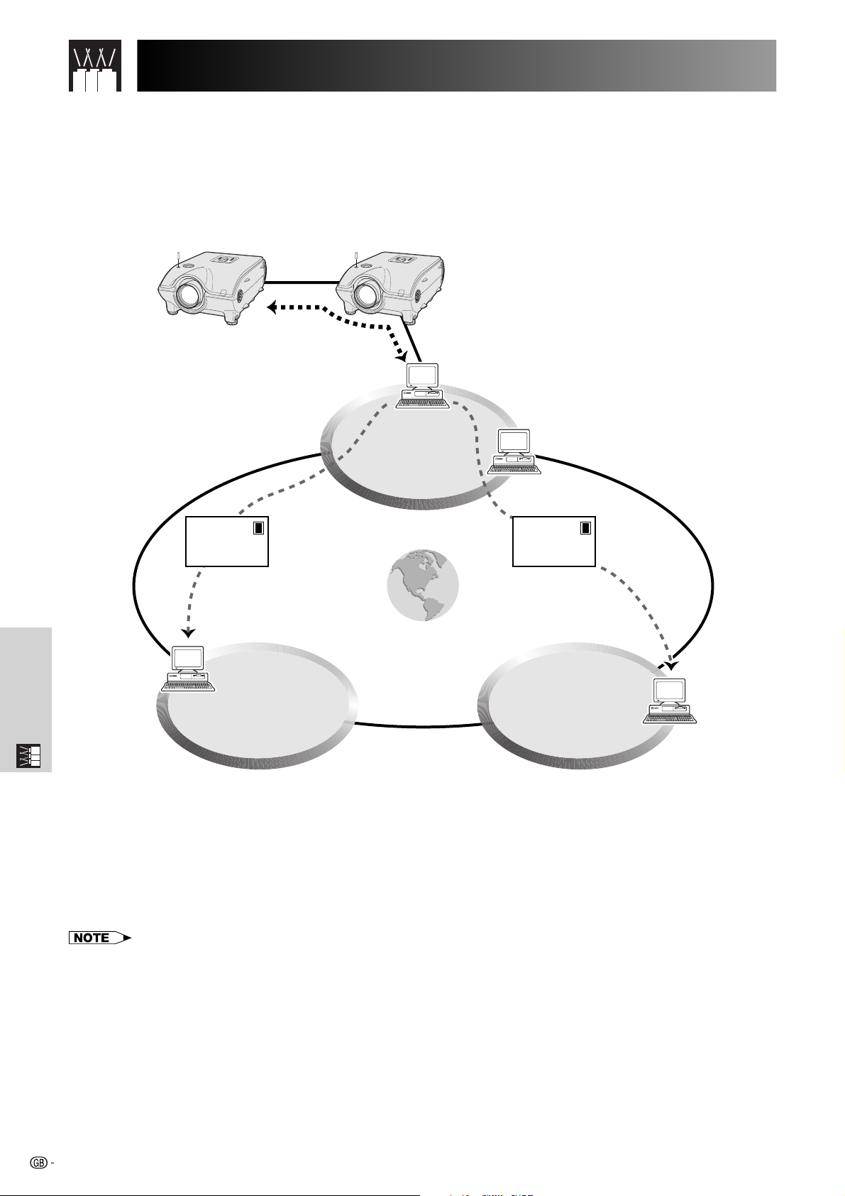
Internet access for self-diagnosis, status information and preventive
maintenance
LAN
E-mail E-mail
Internet
LANLAN
Multiple Function
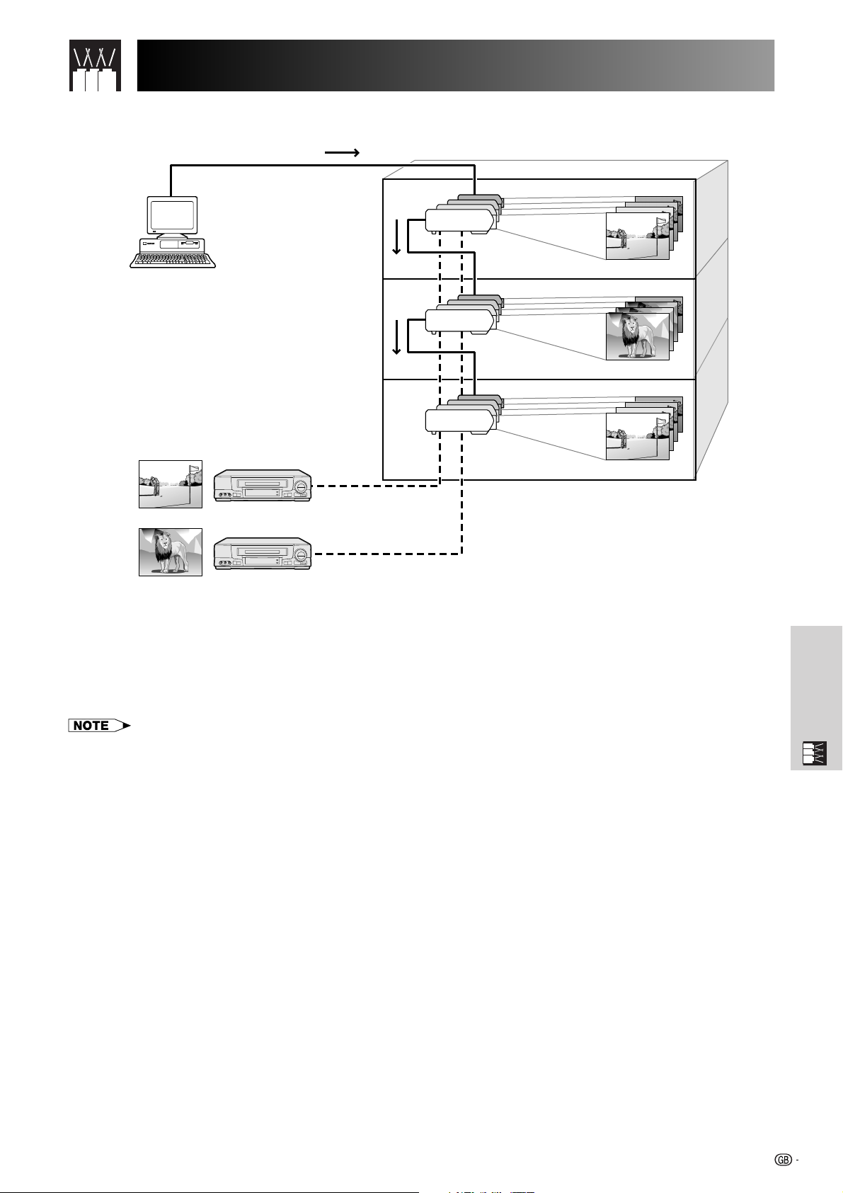
This projector can be used in a network of up to 250 projectors managed from a single PC with the accompanied
Sharp Advanced Presentation Software—Professional Edition. This projector can be connected to a PC using an
RS-232C connection. Output terminals are provided (RS-232C on the projector) enabling a daisy chain configuration
and eliminating the need for a distributor.
This projector is also equipped with a function to send status information (lamp usage time, etc.) to a Sharp
Service Centre or outside contractor for quick and efficient customer service.
• For more information on these features, see the operation manuals accompanying the Sharp Advanced Presentation Software—
Professional Edition and optional boards.
63
(RS-232C) Specifications and Command SettingsUsing Extended Functionality Features
Multiple and group projector control via computer
Control PC
Sharp Advanced
Presentation Software
“Professional Edition”
Video
Source 1
Video
Source 2
RS-232C
RS-232C
RS-232C
RS-232C
RS-232C
Building A
3rd Floor
2nd Floor
1st Floor
This projector can be used in a network of projectors managed from a single PC with the accompanied Sharp
Advanced Presentation Software—Professional Edition. Projectors in conference rooms on the first and third floors
of a building, for example, can be used for video presentations, while projectors on the second floor can be used
for PC-assisted presentations. Projectors can even be powered down at different times (e.g., projectors on the first
and second floors are powered down in one hour, while those on the third floor are powered down in two hours).
• For more information on these features, see the operation manuals accompanying the Sharp Advanced Presentation Software—
Professional Edition.
Multiple Function
64
Using Extended Functionality Features
Simultaneous multiple projector control for stacking and videowall
projection
Stack Projection
Multiple Function
DVD
Distributor
Laser Disc
INPUT1
INPUT2
INPUT4
INPUT5
INPUT1
INPUT2
INPUT4
INPUT5
Master
RS-232C OUTRS-232C IN
RS-232C OUTRS-232C IN
OUTPUT
Slave
OUTPUT
Stack Setting
Master
Stack Setting
Slave
Set Inputs
INPUT1
INPUT2
INPUT3
INPUT4
INPUT5
Set Inputs
INPUT1
INPUT2
INPUT3
INPUT4
INPUT5
Yes
Yes
No
Yes
Yes
Yes
No
No
Yes
Yes
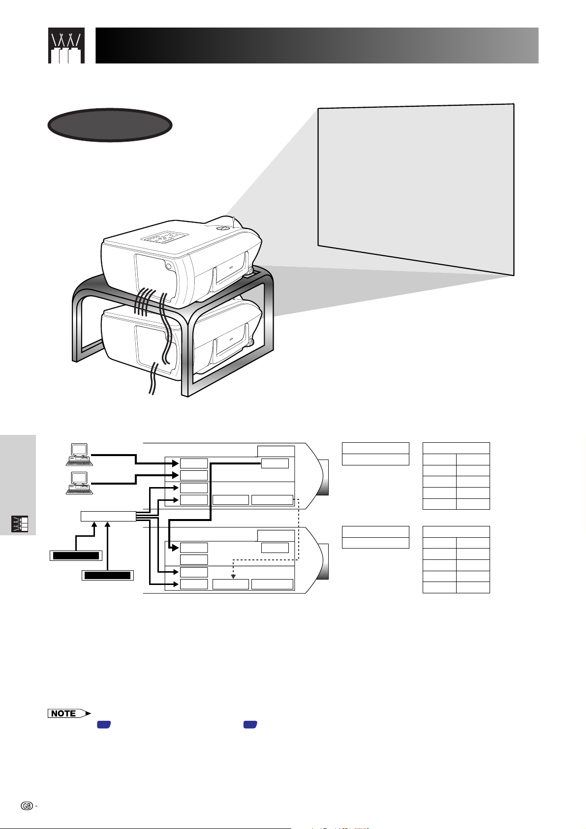
For brighter images, two projectors can be stacked using the Stack Setting function, with one projector set as the
Master and the other as the Slave. The operations of the Slave projector are controlled by the Master projector
during projection through an RS-232C connection. The RS-232C cable (null modem, cross type, sold separately)
is connected from the RS-232C output on the Master projector to the RS-232C input on the Slave projector.
Projectors can be stacked using an RS-232C cable (null modem, cross type, sold separately).
• See page 59, “Deselecting Inputs”, and page 58, “Setting the Stacking Mode”.
65
Using Extended Functionality Features
Videowall
Sharp Advanced
Presentation Software
“Professional Edition”
RGB
SOURCE1
RGB
SOURCE2
Distributor
VIDEO
SOURCE
DVD
Control PC
001
002
INPUT1
INPUT2
INPUT4
INPUT5
INPUT1
INPUT2
INPUT4
INPUT5
RS-232C IN
Master
OUTPUT
RS-232C OUT
Slave
OUTPUT
RS-232C OUTRS-232C IN
003
INPUT1
INPUT2
INPUT4
INPUT5
004
INPUT1
INPUT2
INPUT4
INPUT5
RS-232C OUTRS-232C IN
RS-232C OUTRS-232C IN
Slave
OUTPUT
Slave
OUTPUT
Master
Set Inputs
INPUT1
INPUT2
INPUT3
INPUT4
INPUT5
Set Inputs
INPUT1
INPUT2
INPUT3
INPUT4
INPUT5
Yes
Yes
No
Yes
Yes
Slave
Yes
No
No
Yes
No
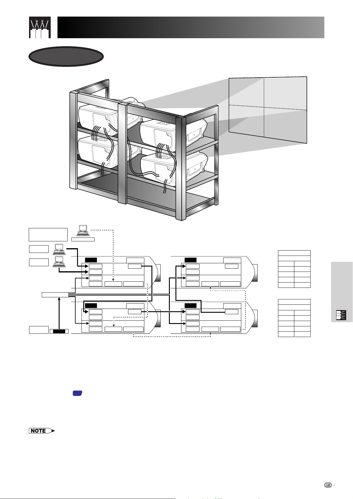
This projector can be used together with other projectors managed using the accompanied Sharp Advanced
Presentation Software—Professional Edition to create a videowall projection. Whereas conventional videowall
technology required the use of an image distributor, this projector videowall feature enables easy image settings
from a PC when inputting a single video source. This function greatly simplifies videowall setup.
RS-232C OUTPUTS also realise the simple daisy chain connection. The master projector directly connected to the
computer can make the daisy chain connection with multiple slave projectors. For details on setting master or
slave, see page 60.
Multiple Function
• Use a videowall projector stand, sold separately, when using this function.
• Image quality may deteriorate when picture signals are input through multiple projectors in a daisy chain
connection.
• For more information on this feature, see the operation manuals accompanying the Sharp Advanced Presentation Software—
Professional Edition.
• When UXGA signal is displayed, the videowall can not be set by Sharp Advanced Presentation Software—Professional
Edition.
66

Lamp/Maintenance Indicators
Maintenance Indicators
POWER
indicator
LAMP
REPLACEMENT
indicator
TEMPERATURE
WARNING
indicator
• The warning lights on the projector indicate problems
inside the projector.
• There are two warning lights: a TEMPERATURE
WARNING indicator that warns you when the projector
is too hot, and two LAMP REPLACEMENT indicators
that warn you when to change a lamp.
• If a problem occurs, either the TEMPERATURE
WARNING indicator or the LAMP REPLACEMENT
indicators will light up red. After turning off the power,
follow the procedures given below.
Maintenance Indicator
TEMPERATURE
WARNING indicator
LAMP REPLACEMENT indicator
POWER indicator
• If the TEMPERATURE WARNING indicator lights up, follow the above possible solutions and then wait until the projector has
cooled down completely before turning the power back on. (At least 5 minutes.)
• If the power is turned off and then turned on again, as during a brief rest, the LAMP REPLACEMENT indicators may be
triggered, preventing the power from going on. Should this occur, take the power cord out of the wall outlet and put it back
in again.
Condition Possible Solution
The internal
temperature is
abnormally high.
The lamp does not
light up.
The POWER
indicator flashes in
red when the
projector is on.
• Blocked air intake.
• Clogged air filter.
• Cooling fan breakdown.
• Internal circuit failure.
• Burnt-out lamp.
• Lamp circuit failure.
• The filter cover is open.
Problem
• Relocate the projector to an area with
proper ventilation.
• Replace the filter.
(See page
• Take the projector to your nearest Sharp
Authorised LCD Projector Dealer or Service
Centre for repair.
• Carefully replace the lamp. (See pages
and 69.)
• Take the projector to your nearest
Authorised LCD Projector Dealer or Service
Centre for repair.
• Securely install the filter cover.
70
.)
68
Lamp
It is recommended that the lamp be replaced after approximately 1,000 cumulative hours of use or when you
notice a significant deterioration of the picture and colour quality. The lamp usage time can be checked with the
On-screen Display. (As the usage environment can vary significantly, the projector lamp may not operate for 1,000
hours.)
Maintenance &
Troubleshooting
CAUTION
• Intense light hazard. Do not attempt to look into the aperture and lens while the projector is operating.
67
Replacing the Lamp
CAUTION
• Potential hazard of glass particles if lamp ruptures. In case of lamp rupture, contact your nearest
Sharp Authorised LCD Projector Dealer or Service Centre for a replacement.
• Do not remove the lamp cage directly after operation of the projector. The lamp may be extremely
hot. Wait at least one hour after the power cord is disconnected to allow the surface of the lamp cage
to fully cool before removing the lamp cage.
It is recommended that the lamp be replaced after approximately 1,000 cumulative hours of use or when you
notice a significant deterioration of the picture and colour quality. Carefully change the lamp by following the steps
below.
If the new lamp does not light after replacement, take your projector to the nearest Sharp Authorised LCD Projector
Dealer or Service Centre for repair. Purchase a replacement lamp unit (lamp/cage module) of the current type
BQC-XGP20X//1 from your nearest Sharp Authorised LCD Projector Dealer or Service Centre. Then carefully
change the lamp by following the instructions below. If you wish, you may have the lamp replaced at your nearest
Sharp Authorised LCD Projector Dealer or Service Centre
Removing and installing the lamp unit
CAUTION
• Be sure to remove the lamp cage by the handle. Be sure not to touch the glass surface of the lamp cage or the inside of
the projector.
• To avoid injury to yourself and damage to the lamp, be sure to carefully follow the steps below.
• Be sure to change the air filter during lamp replacement. The air filter comes packaged with the lamp unit.
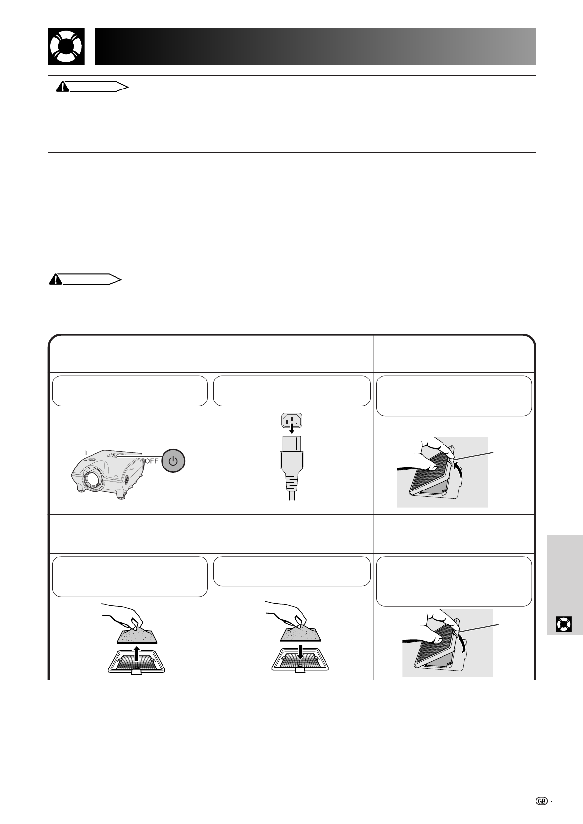
Turn off the power.
1 3
Press POWER OFF. Wait until
the cooling fan stops.
Remove the air filter.
46
Grasp the air filter between your
fingers and lift it out of the filter
cover.
Disconnect the power
2
cord.
Unplug the power cord from the
AC socket.
Replace the air filter.
5
Place the air filter underneath the
tabs on the filter frame.
Remove the bottom
filter cover.
Turn over the projector. Press the
tab and lift open the filter cover
in the direction of the arrow.
Ta b
Replace the filter
cover.
Insert the tab on the end of the
filter cover into the filter cover
opening and press the filter
cover into position.
Ta b
Troubleshooting
Maintenance &
68

Replacing the Lamp
Remove the lamp cage
79
cover.
Turn over the projector and
loosen the user service screw
that secures the lamp cage
cover. Then slide the cover in
the direction of the arrow.
User service screw
Remove the lamp
8
cage.
Remove the securing screws
from the lamp cage. Hold the
lamp cage by the handle and
pull it towards you.
Securing
screw
Securing
screws
Insert the new lamp cage.
Press the lamp cage firmly into
the lamp cage compartment.
Fasten the securing screws.
Attach the lamp cage
10
cover.
Slide the lamp cage cover in
the direction of the arrow. Then
tighten the user service screw.
User service screw
Resetting the lamp timer
Connect the power
1
cord.
Plug the power cord into the AC
socket of the projector.
Maintenance &
Troubleshooting
• Reset the lamp timer only after replacing the lamp.
Reset the lamp timer.
2
While pressing ƒ, © and
ENTER on the projector, press
POWER ON on the projector.
佡
“LAMP 0000H” is displayed,
indicating that the lamp timer is
reset.
69

Replacing the Air Filter
• This projector is equipped with two air filters to ensure the optimal operating condition of the projector.
• The air filters should be cleaned every 100 hours of use. Clean the filters more often when the projector is used
in a dusty or smoky location.
• Have your nearest Sharp Authorised LCD Projector Dealer or Service Centre exchange the filter (PFILD0080CEZZ)
when it is no longer possible to clean it.
Bottom View
Air filter
Side and Rear View
Cleaning and replacing the bottom air filter
Unplug the power
1 3
cord.
Remove the bottom
2
filter cover.
Turn over the projector. Press the
tab and lift open the filter cover
in the direction of the arrow.
Ta b
Air filters (not removable)
Remove the air filter.
Grasp the air filter between your
fingers and lift it out of the filter
cover.
Clean the air filter.
46
Clean the dust off the air filter
and cover with a vacuum
cleaner extension hose.
• Be sure the filter cover is securely installed. The power will not turn on unless it is correctly installed.
Replace the air filter.
5
Place the air filter underneath
the tabs on the filter frame.
Replace the filter
cover.
Insert the tab on the end of the
filter cover into the filter cover
opening and press the filter
cover into position.
Ta b
Troubleshooting
Maintenance &
Cleaning the side air filter (not removable)
If dust or dirt has collected inside the air filter, clean the filter with a vacuum cleaner extension hose.
• The side air filter cannot be removed.
70

Troubleshooting
Power cannot be turned on or
off using the POWER buttons
(ON/OFF) on the projector.
Cannot be operated by
GyroRemote.
Cannot be operated by all
buttons of the projector and
GyroRemote.
No picture and no sound.
Sound is heard but no picture
appears.
Colour is faded or poor.
Picture is blurred.
Picture appears but no sound
is heard.
No OSD appears.
An unusual sound is occasionally heard from the cabinet.
Maintenance indicator lights
up.
Picture noise appears.
480P images do not appear.
Image is green on INPUT 1 or
2 COMPONENT.
Image is pink (no green) on
INPUT 1, 2 RGB.
Maintenance &
Lens comes off.
Troubleshooting
Problem
Check
• Keylock level is set to “Level A” or “Level B”, preventing operation of some or all
buttons. (See page
• Register GyroRemote once again the projector. (See page
58
.)
.)
37
• When the GyroRemote is connected to the projector with wired remote control cable,
confirm the position of the IR/Gyro switch. (See page
38
.)
• When the projector is set to slave, use the buttons on the master projector or change the
setting by RS-232C commands from the computer. (See page
58
.)
• When using slave setting in combination with Keylock Level B, all the buttons on the
projector and the GyroRemote are disabled. Use the SAPS or RS-232C commands to
release slave and Keylock setting and enable buttons to operate.
Without a computer, you can release slave and Keylock setting by entering the buttons
on the projector as follows.
ON
→
ENTER
→ ON →
ENTER
→ ON →
ENTER
→
MENU
However, this operation also releases the password set.
• Projector power cord is not plugged into the wall outlet.
• The bottom filter cover is not securely installed.
• Selected input is wrong. (See page
39
.)
• Cables incorrectly connected to rear panel of the projector. (See pages 13–18.)
• GyroRemote batteries have run down. (See page
• Cables incorrectly connected to rear panel of the projector. (See pages
11
.)
13–18
.)
•“Contrast” and “Bright” adjustments are set to minimum position. (See page 47.)
• On-screen Display (“BLACK SCREEN”) is turned off and Black Screen function is turned
on, creating a black image. (See page
•“Color” and “Tint” adjustments are not correct. (See page
• Adjust the focus. (See page
21
.)
40
.)
.)
47
• Projection distance is too long or too short to allow for proper focus. (See pages 22–28.)
• Cables incorrectly connected to rear panel of the projector. (See pages
• Volume is set to minimum. (See page
39
.)
13–18
.)
• OSD Display is set to “Level A” or “Level B”, preventing to display some or all On-screen
Displays. (See page
54
.)
• If the picture is normal, the sound is due to cabinet shrinkage caused by temperature
changes. This will not affect operation or performance.
• Refer to “Lamp/Maintenance Indicators” on page
• Adjust the “Phase” setting. (See page
49
.)
67
.
• Noise may appear when used with certain computers. Set the NOISE FILTER to ON
50
.)
.)
.)
using the RS-232C command. (See pages
• Set the resolution mode to 480P. (See page
• Change the input signal type. (See page
47
73–75
• Align the mark on the lens with the corresponding mark on the projector, push the lens
firmly in place, and rotate to the right.
71

Connecting Pin Assignments
INPUT 1 RGB and OUTPUT (INPUT 1, 2) Signal Ports: 15-pin Mini D-sub female connector
RGB Input
Analog
1. Video input (red)
2. Video input
(green/sync on green)
3. Video input (blue)
4. Reserve input 1
10
15
5
1
6
11
5. Composite sync
6. Earth (red)
7. Earth (green/sync on green)
Component Input
Analog
R (CR)
1. P
2. Y
B (CB)
3. P
4. Not connected
5. Not connected
6. Earth (P
R)
7. Earth (Y)
8. Earth (P
B)
RS-232C Port: 9-pin D-sub male connector of the DIN-D-sub RS-232C cable
15
69
Pin No. Signal Name I/O Reference
1 CD Not connected
2 RD Receive Data Input Connected to internal circuit
3 SD Send Data Output Connected to internal circuit
4 ER Not connected
5 SG Signal Ground Connected to internal circuit
6 DR Data Set Ready Output Not connected
7 RS Request to Send Output Connected to internal circuit
8 CS Clear to Send Input Connected to internal circuit
9 CI Not connected
8. Earth (blue)
9. Not connected
10. GND
11. GND
12. Bi-directional data
13. Horizontal sync signal
14. Vertical sync signal
15. Data clock
9. Not connected
10. Not connected
11. Not connected
12. Not connected
13. Not connected
14. Not connected
15. Not connected
INPUT 3 DVI Port: 29-pin
C1C2
91 816
C32417 C4
C5
•*1 Return for 5 V, Hsync. and Vsync.
•*2 Analog R, G and B return
•*3 These pins are not used on this equipment.
Pin No. Name
1 T.M.D.S. Data 2
2 T.M.D.S. Data 2
3 T.M.D.S. Data 2/4 Shield
4 T.M.D.S. Data 4*
5 T.M.D.S. Data 4*
3
3
6 DDC Clock
7 DDC Data
8 Analog Vertical Sync
9 T.M.D.S. Data 1
10 T.M.D.S. Data 1
11 T.M.D.S. Data 1/3 Shield
12 T.M.D.S. Data 3*
13 T.M.D.S. Data 3*
14 5 V Power
15 Ground*
1
3
3
16 Hot Plug Detect
17 T.M.D.S. Data 0
18 T.M.D.S. Data 0
19 T.M.D.S. Data 0/5 Shield
20 T.M.D.S. Data 5*
21 T.M.D.S. Data 5*
3
3
22 T.M.D.S. Clock Shield
23 T.M.D.S. Clock
24 T.M.D.S. Clock
C1 Analog Red
C2 Analog Green
C3 Analog Blue
C4 Analog Horizontal sync
C5 Analog Ground*
2
Appendix
72

(RS-232C) Specifications and Command Settings
CONTROL CONTENTS
BLACK SCREEN ON
BLACK SCREEN OFF
INPUT 1 (RGB 1)
INPUT 2 (RGB 2)
INPUT 3 (RGB 3)
INPUT 4 (VIDEO 1)
INPUT 5 (VIDEO 2)
INPUT CHECK
FREEZE ON
FREEZE OFF
AUTO SYNC START
OK OR ERR
OK OR ERR
OK OR ERR
OK OR ERR
OK OR ERR
OK OR ERR
OK OR ERR
OK OR ERR
OK OR ERR
OK OR ERR
OK OR ERR
I
I
I
I
I
I
I
I
F
F
A
M
M
R
R
R
V
V
C
R
R
D
B
B
G
G
G
E
E
H
E
E
J
K
K
B
B
B
D
D
K
Z
Z
S
_
_
_
_
_
_
_
_
_
_
_
_
_
_
_
_
_
_
_
_
_
_
_
_
_
_
_
_
_
_
_
_
_
1
0
1
2
3
1
2
0
1
0
1
BUTTONS & REMOTE CONTROL KEY
COMMAND
PARAMETER
RETURN
PC control
A computer can be used to control the projector by connecting an RS-232C cable (null modem, cross type, sold
separately) to the projector. (See page 16 for connection.)
Communication conditions
Set the serial port settings of the computer to match that of the table.
Signal format: Conforms to RS-232C standard.
Baud rate: 9,600 bps
Data length: 8 bits
Parity bit: NON
Stop bit: 1 bit
Flow control: None
Basic format
Commands from the computer are sent in the following order: command, parameter, and return code. After the
projector processes the command from the computer, it sends a response code to the computer.
Command format
C1 C2 C3 C4 P1 P2 P3 P4
Return code (0DH)
Command 4-digit Parameter 4-digit
Response code format
Normal response
O K
Return code (0DH)
Problem response (communication error or incorrect command)
E R R
Return code (0DH)
When more than one code is being sent, send each command only after the OK response code for the previous
command from the projector is verified.
• When using the computer control function of the projector, the projector operating status cannot be read to the computer.
Therefore, confirm the status by transmitting the display commands for each adjustment menu and checking the status with
the On-screen Display. If the projector receives a command other than a menu display command, it will execute the command without displaying the On-screen Display.
Commands
EXAMPLE
• When “BRIGHT” of INPUT 1 IMAGE ADJUSTMENT is set to 10.
ProjectorComputer
RABR 1 0_
→
←
OK
POWER ON
POWER OFF
VOLUME (0–60)
MUTE ON
MUTE OFF
LENS FOCUS (30 – 30)
Appendix
LENS ZOOM (30 – 30)
KEYSTONE (127 – 127)
V-SIZE (30 – 30)
BUTTONS & REMOTE CONTROL KEY
DIGITAL SHIFT (30 – 30)
73
CONTROL CONTENTS
COMMAND
PARAMETER
P
O
W
R
_
_
_
P
O
W
R
_
_
_
V
O
L
A
_
_
*
M
U
T
E
_
_
_
M
U
T
E
_
_
_
L
N
F
O
_
*
*
L
N
Z
O
_
*
*
K
E
Y
S
*
*
V
S
L
N
*
I
Z
_
_
*
D
S
_
*
*
OK OR ERR
1
OK OR ERR
0
OK OR ERR
*
OK OR ERR
1
OK OR ERR
0
OK OR ERR
*
OK OR ERR
*
OK OR ERR
*
OK OR ERR
*
OK OR ERR
*
RETURN

(RS-232C) Specifications and Command Settings
CONTROL CONTENTS
INPUT 1 (RGB 1) SIGNAL TYPE : RGB
INPUT 1 (RGB 1) SIGNAL TYPE : COMPONENT
INPUT 2 (RGB 2) SIGNAL TYPE : RGB
INPUT 2 (RGB 2) SIGNAL TYPE : COMPONENT
INPUT 1 (RGB 1) 2D PROGRESSIVE
INPUT 1 (RGB 1) 3D PROGRESSIVE
INPUT 1 (RGB 1) Film MODE
INPUT 2 (RGB 2) 2D PROGRESSIVE
INPUT 2 (RGB 2) 3D PROGRESSIVE
INPUT 2 (RGB 2) Film MODE
INPUT 3 (RGB 3) 2D PROGRESSIVE
INPUT 3 (RGB 3) 3D PROGRESSIVE
INPUT 3 (RGB 3) Film MODE
INPUT 4 (VIDEO 1) CONTRAST (30 – 30)
INPUT 4 (VIDEO 1) BRIGHT (30 – 30)
INPUT 4 (VIDEO 1) RED (30 – 30)
INPUT 4 (VIDEO 1) BLUE (30 – 30)
INPUT 4 (VIDEO 1) COLOR (30 – 30)
INPUT 4 (VIDEO 1) TINT (30 – 30)
INPUT 4 (VIDEO 1) SHARP (30 – 30)
INPUT 4 (VIDEO 1) CLR TEMP (3 – 3)
INPUT 4 (VIDEO 1) DISPLAY
INPUT 4 (VIDEO 1) ADJUSTMENT RESET
INPUT 5 (VIDEO 2) CONTRAST (30 – 30)
INPUT 5 (VIDEO 2) BRIGHT (30 – 30)
INPUT 5 (VIDEO 2) RED (30 – 30)
INPUT 5 (VIDEO 2) BLUE (30 – 30)
INPUT 5 (VIDEO 2) COLOR (30 – 30)
INPUT 5 (VIDEO 2) TINT (30 – 30)
INPUT 5 (VIDEO 2) SHARP (30 – 30)
INPUT 5 (VIDEO 2) CLR TEMP (3 – 3)
INPUT 5 (VIDEO 2) DISPLAY
INPUT 5 (VIDEO 2) ADJUSTMENT RESET
INPUT 4 (VIDEO 1) 2D PROGRESSIVE
INPUT 4 (VIDEO 1) 3D PROGRESSIVE
INPUT 4 (VIDEO 1) Film MODE
INPUT 5 (VIDEO 2) 2D PROGRESSIVE
INPUT 5 (VIDEO 2) 3D PROGRESSIVE
INPUT 5 (VIDEO 2) Film MODE
(INPUT 1–5) 2D PROGRESSIVE
(INPUT 1–5) 3D PROGRESSIVE
(INPUT 1–5) Film MODE
CLOCK (150 – 150)
PHASE (60 – 60)
H-POSITION (150 – 150)
V-POSITION (60 – 60)
RGB INPUT DISPLAY
RGB ADJUSTMENT RESET
SAVE SETTING (1 – 7)
SELECT SETTING (1 – 7)
RGB HORIZONTAL FREQUENCY CHECK
RGB VERTICAL FREQUENCY CHECK
AUTO SYNC OFF
NORMAL AUTO SYNC
HIGH SPEED AUTO SYNC
AUTO SYNC DISPLAY ON
AUTO SYNC DISPLAY OFF
OK OR ERR
OK OR ERR
OK OR ERR
OK OR ERR
OK OR ERR
OK OR ERR
OK OR ERR
OK OR ERR
OK OR ERR
OK OR ERR
OK OR ERR
OK OR ERR
OK OR ERR
OK OR ERR
OK OR ERR
OK OR ERR
OK OR ERR
OK OR ERR
OK OR ERR
OK OR ERR
OK OR ERR
OK OR ERR
OK OR ERR
OK OR ERR
OK OR ERR
OK OR ERR
OK OR ERR
OK OR ERR
OK OR ERR
OK OR ERR
OK OR ERR
OK OR ERR
OK OR ERR
OK OR ERR
OK OR ERR
OK OR ERR
OK OR ERR
OK OR ERR
OK OR ERR
OK OR ERR
OK OR ERR
OK OR ERR
OK OR ERR
OK OR ERR
OK OR ERR
OK OR ERR
OK OR ERR
OK OR ERR
OK OR ERR
OK OR ERR
kHz (***. * OR _)
Hz (***. * OR _)
OK OR ERR
OK OR ERR
OK OR ERR
OK OR ERR
OK OR ERR
I
I
I
I
R
R
R
R
R
R
R
R
R
V
V
V
V
V
V
V
V
V
V
V
V
V
V
V
V
V
V
V
V
V
V
V
V
V
V
I
I
I
I
I
I
I
I
I
M
M
T
T
A
A
A
I
I
A
A
B
B
A
A
A
B
B
B
C
C
C
A
A
A
A
A
A
A
A
A
A
B
B
B
B
B
B
B
B
B
B
A
A
A
B
B
B
M
M
M
N
N
A
A
A
A
E
E
F
F
A
A
A
M
M
S
S
S
S
I
I
I
I
I
I
I
I
I
P
B
R
B
C
T
S
C
R
R
P
B
R
B
C
T
S
C
R
R
I
I
I
I
I
I
I
I
I
C
P
H
V
R
R
M
M
R
R
D
D
D
A
A
I
I
I
I
P
P
P
P
P
P
P
P
P
I
R
D
E
O
I
H
T
E
E
I
R
D
E
O
I
H
T
E
E
P
P
P
P
P
P
P
P
P
L
H
P
P
E
E
S
L
Q
Q
J
J
J
S
S
_
_
_
_
_
_
_
_
_
_
_
_
_
_
_
_
_
_
_
_
_
_
_
_
_
_
_
_
_
_
_
_
_
_
_
_
_
_
_
_
_
_
*
_
*
_
_
_
_
_
_
_
_
_
_
_
_
_
_
_
_
_
_
_
_
_
_
_
_
_
*
*
*
*
*
*
*
_
_
_
*
*
*
*
*
*
*
_
_
_
_
_
_
_
_
_
_
_
_
*
*
*
*
_
_
_
_
_
_
_
_
_
_
_
_
_
_
_
_
_
_
_
_
_
_
_
_
*
*
*
*
*
*
*
*
_
_
*
*
*
*
*
*
*
*
_
_
_
_
_
_
_
_
_
_
_
*
*
*
*
_
_
_
_
_
_
_
_
_
_
_
0
1
0
1
0
1
2
0
1
2
0
1
2
*
*
*
*
*
*
*
*
0
1
*
*
*
*
*
*
*
*
0
1
0
1
2
0
1
2
0
1
2
*
*
*
*
0
1
*
*
1
2
0
1
2
1
0
PICTUREFINE SYNC
*1
COMMAND
PARAMETER
RETURN
CONTROL CONTENTS
INPUT 1 (RGB 1) RESIZE : NORMAL
INPUT 1 (RGB 1) RESIZE : FULL
INPUT 1 (RGB 1) RESIZE : DOT BY DOT
INPUT 2 (RGB 2) RESIZE : NORMAL
INPUT 2 (RGB 2) RESIZE : FULL
INPUT 2 (RGB 2) RESIZE : DOT BY DOT
INPUT 3 (RGB 3) RESIZE : NORMAL
INPUT 3 (RGB 3) RESIZE : FULL
INPUT 3 (RGB 3) RESIZE : DOT BY DOT
INPUT 4 (VIDEO 1) RESIZE : NORMAL
INPUT 4 (VIDEO 1) RESIZE : FULL
INPUT 4 (VIDEO 1) RESIZE : BORDER
INPUT 4 (VIDEO 1) RESIZE : STRETCH
INPUT 4 (VIDEO 1) RESIZE : SMART STRETCH
INPUT 5 (VIDEO 2) RESIZE : NORMAL
INPUT 5 (VIDEO 2) RESIZE : FULL
INPUT 5 (VIDEO 2) RESIZE : BORDER
BUTTONS & REMOTE CONTROL KEYPICTURE
INPUT 5 (VIDEO 2) RESIZE : STRETCH
INPUT 5 (VIDEO 2) RESIZE : SMART STRETCH
RGB GAMMA : STANDARD
RGB GAMMA : PRESENTATION
RGB GAMMA : CINEMA
RGB GAMMA : CUSTOM
VIDEO GAMMA : STANDARD
VIDEO GAMMA : PRESENTATION
VIDEO GAMMA : CINEMA
VIDEO GAMMA : CUSTOM
INPUT 1 (RGB 1) CONTRAST (30 – 30)
INPUT 1 (RGB 1) BRIGHT (30 – 30)
INPUT 1 (RGB 1) RED (30 – 30)
INPUT 1 (RGB 1) BLUE (30 – 30)
INPUT 1 (RGB 1) COLOR (30 – 30)
INPUT 1 (RGB 1) TINT (30 – 30)
INPUT 1 (RGB 1) SHARP (30 – 30)
INPUT 1 (RGB 1) CLR TEMP (3 – 3)
INPUT 1 (RGB 1) DISPLAY
INPUT 1 (RGB 1) ADJUSTMENT RESET
INPUT 2 (RGB 2) CONTRAST (30 – 30)
INPUT 2 (RGB 2) BRIGHT (30 – 30)
INPUT 2 (RGB 2) RED (30 – 30)
INPUT 2 (RGB 2) BLUE (30 – 30)
INPUT 2 (RGB 2) COLOR (30 – 30)
INPUT 2 (RGB 2) TINT (30 – 30)
INPUT 2 (RGB 2) SHARP (30 – 30)
INPUT 2 (RGB 2) CLR TEMP (3 – 3)
INPUT 2 (RGB 2) DISPLAY
INPUT 2 (RGB 2) ADJUSTMENT RESET
INPUT 3 (RGB 3) CONTRAST (30 – 30)
INPUT 3 (RGB 3) BRIGHT (30 – 30)
INPUT 3 (RGB 3) RED (30 – 30)
INPUT 3 (RGB 3) BLUE (30 – 30)
INPUT 3 (RGB 3) COLOR (30 – 30)
INPUT 3 (RGB 3) TINT (30 – 30)
INPUT 3 (RGB 3) SHARP (30 – 30)
INPUT 3 (RGB 3) CLR TEMP (3 – 3)
INPUT 3 (RGB 3) DISPLAY
INPUT 3 (RGB 3) ADJUSTMENT RESET
COMMAND
S
A
R
S
A
R
S
A
R
S
B
R
S
B
R
S
B
R
S
C
R
S
C
R
S
C
R
S
A
R
S
A
R
S
A
R
S
A
R
S
A
R
S
B
R
S
B
R
S
B
R
S
B
R
S
B
R
M
A
G
M
A
G
M
A
G
M
A
G
M
A
G
M
A
G
M
A
G
M
A
G
P
A
R
B
A
R
R
A
R
B
A
R
C
A
R
T
A
R
S
A
R
C
A
R
R
A
R
R
A
R
P
B
R
B
B
R
R
B
R
B
B
R
C
B
R
T
B
R
S
B
R
C
B
R
R
B
R
R
B
R
P
C
R
B
C
R
R
C
R
B
C
R
C
C
R
T
C
R
C
C
R
C
C
R
R
C
R
R
C
R
PARAMETER
_
R
_
R
_
R
_
R
_
R
_
R
_
R
_
R
_
R
_
V
_
V
_
V
_
V
_
V
_
V
_
V
_
V
_
V
_
V
_
R
_
R
_
R
_
R
_
V
_
V
_
V
_
V
_
I
_
R
_
D
_
E
_
O
_
I
_
H
_
T
_
E
_
E
_
I
_
R
_
D
_
E
_
O
_
I
_
H
_
T
_
E
_
E
_
I
_
R
_
D
_
E
_
O
_
I
_
H
_
T
_
E
_
E
RETURN
1
_
_
OK OR ERR
5
_
_
OK OR ERR
3
_
_
OK OR ERR
1
_
_
OK OR ERR
5
_
_
OK OR ERR
3
_
_
OK OR ERR
1
_
_
OK OR ERR
5
_
_
OK OR ERR
3
_
_
OK OR ERR
1
_
_
OK OR ERR
5
_
_
OK OR ERR
3
_
_
OK OR ERR
2
_
_
OK OR ERR
4
_
_
OK OR ERR
1
_
_
OK OR ERR
5
_
_
OK OR ERR
3
_
_
OK OR ERR
2
_
_
OK OR ERR
4
_
_
OK OR ERR
1
_
_
OK OR ERR
2
_
_
OK OR ERR
3
_
_
OK OR ERR
4
_
_
OK OR ERR
1
_
_
OK OR ERR
2
_
_
OK OR ERR
3
_
_
OK OR ERR
4
_
_
OK OR ERR
*
*
*
OK OR ERR
*
*
*
OK OR ERR
*
*
*
OK OR ERR
*
*
*
OK OR ERR
*
*
*
OK OR ERR
*
*
*
OK OR ERR
*
*
*
OK OR ERR
*
*
_
OK OR ERR
0
_
_
OK OR ERR
1
_
_
OK OR ERR
*
*
*
OK OR ERR
*
*
*
OK OR ERR
*
*
*
OK OR ERR
*
*
*
OK OR ERR
*
*
*
OK OR ERR
*
*
*
OK OR ERR
*
*
*
OK OR ERR
*
*
_
OK OR ERR
0
_
_
OK OR ERR
1
_
_
OK OR ERR
*
*
*
OK OR ERR
*
*
*
OK OR ERR
*
*
*
OK OR ERR
*
*
*
OK OR ERR
*
*
*
OK OR ERR
*
*
*
OK OR ERR
*
*
*
OK OR ERR
*
*
_
OK OR ERR
0
_
_
OK OR ERR
1
_
_
OK OR ERR
Appendix
74

(RS-232C) Specifications and Command Settings
CONTROL CONTENTS
LAMP USAGE TIME
LAMP STATUS
PRJ MODE : REVERSE OFF
PRJ MODE : REVERSE ON
PRJ MODE : INVERT OFF
PRJ MODE : INVERT ON
STACK SETTING : NORMAL
STACK SETTING : MASTER
STACK SETTING : SLAVE
KEYLOCK LEVEL : NORMAL
KEYLOCK LEVEL : LEVEL A
KEYLOCK LEVEL : LEVEL B
SET INPUTS : INPUT 1 NO USE
SET INPUTS : INPUT 1 USE
SET INPUTS : INPUT 2 NO USE
SET INPUTS : INPUT 2 USE
SET INPUTS : INPUT 3 NO USE
SET INPUTS : INPUT 3 USE
SET INPUTS : INPUT 4 NO USE
SET INPUTS : INPUT 4 USE
SET INPUTS : INPUT 5 NO USE
SET INPUTS : INPUT 5 USE
ID NO. CHECK
LANGUAGE SELECTION : ENGLISH
LANGUAGE SELECTION : DEUTSCH
LANGUAGE SELECTION : ESPAÑOL
LANGUAGE SELECTION : NEDERLANDS
LANGUAGE SELECTION : FRANÇAIS
LANGUAGE SELECTION : ITALIANO
LANGUAGE SELECTION : SVENSKA
LANGUAGE SELECTION :
LANGUAGE SELECTION : PORTUGUÊS
LANGUAGE SELECTION :
LANGUAGE SELECTION :
MODEL NAME CHECK
NOISE FILTER OFF
NOISE FILTER ON
*2
SERIAL NO. CHECK
*3
PROJECTOR NAME SETTING
*4
PROJECTOR NAME CHECK
0–9999 (INTEGER)
0:OFF, 1:ON, 2:RETRY,
3:WAITING, 4:LAMP ERROR
OK OR ERR
OK OR ERR
OK OR ERR
OK OR ERR
OK OR ERR
OK OR ERR
OK OR ERR
OK OR ERR
OK OR ERR
OK OR ERR
OK OR ERR
OK OR ERR
OK OR ERR
OK OR ERR
OK OR ERR
OK OR ERR
OK OR ERR
OK OR ERR
OK OR ERR
OK OR ERR
001–250
OK OR ERR
OK OR ERR
OK OR ERR
OK OR ERR
OK OR ERR
OK OR ERR
OK OR ERR
OK OR ERR
OK OR ERR
OK OR ERR
OK OR ERR
MODEL NAME
OK OR ERR
OK OR ERR
SERIAL NO.
OK OR ERR
PROJECTOR NAME
T
T
I
I
I
I
S
S
S
K
K
K
R
R
R
R
R
R
V
V
V
V
R
M
M
M
M
M
M
M
M
M
M
M
M
N
N
S
P
P
L
L
M
M
M
M
T
T
T
E
E
E
A
A
B
B
C
C
A
A
B
B
D
E
E
E
E
E
E
E
E
E
E
E
N
F
F
N
J
J
T
P
R
R
I
I
A
A
A
Y
Y
Y
S
S
S
S
S
S
S
S
S
S
I
L
L
L
L
L
L
L
L
L
L
L
R
I
I
R
N
N
T
S
E
E
N
N
K
K
K
L
L
L
I
I
I
I
I
I
I
I
I
I
D
A
A
A
A
A
A
A
A
A
A
A
D
L
L
D
A
A
_
_
_
_
_
_
_
_
_
_
_
_
_
_
_
_
_
_
_
_
_
_
_
_
_
_
_
_
_
_
_
_
_
_
_
_
_
_
_
_
_
_
_
_
_
_
_
_
_
_
_
_
_
_
_
_
_
_
_
_
_
_
_
_
_
_
_
_
_
_
_
_
_
_
_
_
_
_
_
_
_
_
_
_
_
_
_
_
_
_
_
_
_
_
_
_
_
_
_
_
_
_
_
_
_
_
_
_
_
_
_
_
_
1
_
_
_
_
_
_
1
1
0
1
0
1
0
1
2
0
1
2
0
1
0
1
0
1
0
1
0
1
1
0
1
2
3
4
5
6
7
8
9
0
1
0
1
1
1
2
OPTIONS (2)LANGUAGE
COMMAND
PARAMETER
RETURN
BALANCE (30 – 30)
TREBLE (30 – 30)
BASS (30 – 30)
AUDIO DISPLAY
AUDIO ADJUSTMENT RESET
AUDIOOPTIONS (1)
FAO
VAO
SPEAKER ON
SPEAKER OFF
PICT IN PICT : BOTTOM RIGHT
PICT IN PICT : BOTTOM LEFT
PICT IN PICT : UPPER RIGHT
PICT IN PICT : UPPER LEFT
PICT IN PICT RESET
VIDEO DNR OFF
VIDEO DNR ON
OSD DISPLAY ON
OSD DISPLAY OFF (LEVEL A)
OSD DISPLAY OFF (LEVEL B)
BLACK SCREEN DISPLAY ON
BLACK SCREEN DISPLAY OFF
VIDEO SYSTEM SELECTION : AUTO
VIDEO SYSTEM SELECTION : PAL
VIDEO SYSTEM SELECTION : SECAM
VIDEO SYSTEM SELECTION : NTSC4.43
VIDEO SYSTEM SELECTION : NTSC3.58
VIDEO SYSTEM SELECTION : PAL_M
VIDEO SYSTEM SELECTION : PAL_N
BACKGROUND SELECTION : SHARP
Appendix
BACKGROUND SELECTION : CUSTOM
BACKGROUND SELECTION : BLUE
BACKGROUND SELECTION : NONE
STARTUP IMAGE SELECTION : SHARP
STARTUP IMAGE SELECTION : CUSTOM
STARTUP IMAGE SELECTION : NONE
MONITOR OUT OFF
MONITOR OUT ON
AUTO POWER OFF : NO USE
AUTO POWER OFF : USE
• If an underbar (_) appears in the parameter column, enter a space. If an asterisk (*) appears, enter a value in the range
indicated in brackets under CONTROL CONTENTS.
*1
FINE SYNC can only be set in the displayed RGB mode.
•
•*2Noise may appear when used with certain computers. Set the NOISE FILTER to ON using the RS-232C command.
*3
SERIAL NO. CHECK command is used to read out the 12 digits of serial No..
•
*4
After OK is returned, enter PROJECTOR NAME, up to 12-character memory. The PROJECTOR NAME in memory can then
•
be output (confirmed).
75
CONTROL CONTENTS
COMMAND
A
A
B
A
A
T
A
A
B
A
A
R
A
A
R
A
O
U
A
O
U
A
S
P
A
S
P
P
I
N
P
I
N
P
I
N
P
I
N
P
I
N
3
D
N
3
D
N
I
M
D
I
M
D
I
M
D
I
M
B
I
M
B
M
E
S
M
E
S
M
E
S
M
E
S
M
E
S
M
E
S
M
E
S
I
M
B
I
M
B
I
M
B
I
M
B
I
M
S
I
M
S
I
M
S
M
O
U
M
O
U
A
P
O
A
P
O
PARAMETER
L
_
E
_
A
_
E
_
E
_
T
_
T
_
K
_
K
_
P
_
P
_
P
_
P
_
P
_
R
_
R
_
I
_
I
_
I
_
O
_
O
_
Y
_
Y
_
Y
_
Y
_
Y
_
Y
_
Y
_
G
_
G
_
G
_
G
_
I
_
I
_
I
_
T
_
T
_
W
_
W
_
RETURN
OK OR ERR
*
*
*
OK OR ERR
*
*
*
OK OR ERR
*
*
*
OK OR ERR
_
_
0
OK OR ERR
_
_
1
OK OR ERR
_
_
1
OK OR ERR
_
_
2
OK OR ERR
_
_
1
OK OR ERR
_
_
0
OK OR ERR
_
1
1
OK OR ERR
_
1
2
OK OR ERR
_
1
3
OK OR ERR
_
1
4
OK OR ERR
_
_
0
OK OR ERR
_
_
0
OK OR ERR
_
_
1
OK OR ERR
_
_
1
OK OR ERR
_
_
2
OK OR ERR
_
_
0
OK OR ERR
_
_
1
OK OR ERR
_
_
0
OK OR ERR
_
_
1
OK OR ERR
_
_
2
OK OR ERR
_
_
3
OK OR ERR
_
_
4
OK OR ERR
_
_
5
OK OR ERR
_
_
6
OK OR ERR
_
_
7
OK OR ERR
_
_
1
OK OR ERR
_
_
2
OK OR ERR
_
_
3
OK OR ERR
_
_
4
OK OR ERR
_
_
1
OK OR ERR
_
_
2
OK OR ERR
_
_
3
OK OR ERR
_
_
0
OK OR ERR
_
_
1
OK OR ERR
_
_
0
OK OR ERR
_
_
1

Wired Remote Control Terminal Specifications
Specifications of wired remote control input
• ø3.5 mm minijack
• External: 5 V (1 A)
• Internal: GND
Function and transmission codes
CONTROL
ITEM
ON
OFF
VOLUME
VOLUME
MUTE
MENU
LENS
BLACK SCREEN
ENTER
RESIZE
UNDO
SYSTEM CODE
C1
C2
C3
0
1
1
0
1
1
0
1
1
0
1
1
0
1
1
0
1
1
0
1
1
0
1
1
0
1
1
0
1
1
0
1
1
C4
1
1
1
1
1
1
1
1
1
1
1
C5 C6
0
0
0
0
0
0
0
0
0
0
0
DATA CODE
C7
1
0
1
0
0
0
0
1
1
1
0
0
1
1
0
1
1
1
1
0
0
1
C8
C9
C10 C11
1
0
1
0
1
0
1
0
1
0
1
0
0
1
0
1
1
0
1
1
0
1
EXTERNAL
CODE
C12
C13
C14
C15
1
1
1
1
1
1
0
0
0
1
1
1
0
0
0
0
0
0
0
0
1
0
0
0
1
0
0
1
1
0
0
0
1
0
0
0
1
0
0
0
1
0
1
1
1
0
0
1
1
0
1
0
1
0
1
0
1
0
1
0
1
0
1
0
1
0
• To operate the mouse, left-click and right-click functions
through the wired remote control input, connect the cable
from the WIRED REMOTE control input terminal on the
projector to the remote control. The codes for these functions
are complex and are, therefore, not listed here.
Sharp remote control signal format
Transmission format: 15-bit format
CONTROL
ITEM
Freeze
Enlarge
AUTO SYNC
∂
ƒ
ß
©
GAMMA
INPUT 1. 2. 3
INPUT 4. 5
SYSTEM CODE
C1
C2
C3
0
1
1
0
1
1
0
1
1
0
1
1
0
1
1
0
1
1
0
1
1
0
1
1
0
1
1
0
1
1
C4
1
1
1
1
1
1
1
1
1
1
C5 C6
0
0
0
0
0
0
0
0
0
0
DATA CODE
C7
0
1
0
1
1
0
0
0
0
1
0
0
1
1
0
0
0
0
1
0
C8
C9
C10 C11
1
1
1
1
0
1
1
1
1
1
0
0
1
1
0
0
1
1
1
0
EXTERNAL
CODE
C12
C13
C14
C15
0
0
0
1
1
1
1
0
0
0
1
1
0
1
1
0
0
0
0
0
1
1
1
0
1
0
1
0
1
1
1
0
0
1
1
0
0
1
1
0
1
0
1
0
1
0
1
0
1
0
1
0
1
1
1
0
0
1
1
1
Wired remote control function code
LSB MSB
C1 System Code C5 C6 Data Code C13 C14 C15
10110********10
• System codes C1 to C5 are fixed at “10110”.
• Codes C14 and C15 are reverse confirmation bits, with “10”
indicating “Front” and “01” indicating “Rear”.
DDDDDD
67.5 ms 67.5 ms
DDDDDDD
Wave form of output signal: Output using Pulse Position Modulation
t
T
0
T
1
• t 264 µs
• T0 1.05 ms
“0”“0”“0”“1”
D
“0”“1”“0”
• Pulse carrier frequency 455/12 kHz
• Duty ratio 1:1
26.4 µs
• T1 2.10 ms
Transmission control code
15 bit
C1 C2 C3 C4 C5 C6 C7 C8 C9 C10 C11 C12 C13 C14
System Address
D to D Common Data Bit Reverse in D
Function Key Data Bit
Data
Expansion
Mask
C15
Deter-
mination
Example of Reverse D to
C11DC20C31C41C50C61C70C80C90C100C110C120C130C141C15
Data
C11DC20C31C41C50C60C71C81C91C101C111C121C131C140C15
t
0
1
Appendix
76

Computer Compatibility Chart
Horizontal Frequency: 15–126 kHz
Vertical Frequency: 43–200 Hz
Pixel Clock: 12–230 MHz
Compatible with sync on green and composite sync signals
UXGA and SXGA compatible in advanced intelligent compression or intelligent compression
AICS (Advanced Intelligent Compression and Expansion System) resizing technology
PC/
MAC/
WS
PC
VGA
SVGA
XGA
Resolution
640 350
720 350
640 400
720 400
640 480
800 600
1,024 768
Horizontal
Frequency
(kHz)
27.0 60
31.5 70
37.9 85
27.0 60
31.5 70
27.0 60
31.5 70
37.9
27.0
31.5
37.9
26.2
31.5
34.7
37.9
37.5
43.3
47.9
53.0
61.8
78.5
80.9
100.4 200
31.4 50
35.1 56
37.9 60
44.5 70
48.1 72
46.9 75
53.7 85
56.8 90
64.0 100
77.2 120
98.3 150
102.1 160
125.6 200
35.5 43
40.3 50
56.5 70
58.1 72
68.7 85
73.5 90
77.2 96
80.6 100
98.8 120
113.2 140
125.6 150
Vertical
Frequency
(Hz)
85
60
70
85
50
60
70
72
75
85
90
100
120
150
160
VESA
Standard
Display
Upscale
True
PC/
MAC/
WS
PC
PC/
MAC 13"
PC/
MAC 19"
PC/
MAC 21"
MAC 16"
MAC 21"
HP (WS)
PC (WS)
WS
SGI (WS)
SUN (WS)
Horizontal
Resolution Display
1,152 864
SXGA
1,152 882
1,280 1,024
1,600 1,200
UXGA
640 480
VGA
XGA
1,024 768
1,280 1,024
SXGA
832 624
SVGA
1,152 870
SXGA
1,280 1,024
1,280 960
SXGA
1,280 1,024
1,152 900
Frequency
(kHz)
54.3 60
64.0 70
64.1 72
67.5 75
75.7 80
77.3 85
90.2 100
111.1 120
54.8 60
65.9 72
67.4 74
64.0 60
74.6 70
78.1 74
75.7 75
91.1 85
108.4 100
74.7 52
75.0 60
81.3 65
87.5 70
90.1 72
93.8 75
106.3 85
34.9
48.4 60
60.0
80.0
46.8 75
49.6 75
68.5
78.1 72
60.0 60
85.9 85
53.5 50
76.8 72
60.9 66
71.9 76
Vertical
Frequency
(Hz)
67
75
75
75
VESA
Standard
Advanced
Intelligent
Compression
Intelligent
Compression
Upscale
True
Advanced
Intelligent
Compression
Upscale
Advanced
Intelligent
Compression
• This projector may not be able to display images from notebook computers in simultaneous (CRT/LCD) mode. Should this
occur, turn off the LCD display on the notebook computer and output the display data in “CRT only” mode. Details on how
to change display modes can be found in your notebook computer’s operation manual.
• This projector can receive 640 350 VESA format VGA signals, however, “640 400” will appear on the screen.
Appendix
• When receiving 1,600 1,200 VESA format UXGA signals, sampling occurs and the image is displayed with 1,024 lines,
causing part of the image to be blocked.
77

Dimensions
Rear View
Side View
Front View
4383
65 7116.5
Top View
319 3.5
23
423
Side View
155
79
282.5
26.5
Bottom View
34
248
Appendix
Units: mm
78

Specifications
Product type
Model
Video system
Display method
LCD panel
Standard Lens
Projection lamp
Contrast ratio
Video input signal
S-video input signal
Component input signal
Horizontal resolution
RGB input signal
Pixel clock
Vertical frequency
Horizontal frequency
Computer control signal
Speaker system
Rated voltage
Input current
Rated frequency
Power consumption
Power dissipation
Operating temperature
Storage temperature
Cabinet
GyroRemote
Dimensions (approx.)
Weight (approx.)
Supplied accessories
Replacement parts
LCD Projector
XG-P20XE
PAL/PAL 60/PAL-M/PAL-N/SECAM/NTSC 3.58/NTSC 4.43
DTV 480P/720P/1080i
LCD panel 3, RGB optical shutter method
Panel size: 33 mm (1.3) (20.0 [H] 26.6 [W] mm)
Display method: Translucent TN liquid crystal panel
Drive method: TFT (Thin Film Transistor) Active Matrix panel
No. of dots: 786,432 dots (1,024 [H] 768 [V])
1–1.3 zoom lens, F1.7–2.3, f = 49.1–63.8 mm
AC 220 W lamp
400:1
RCA Connector: VIDEO, composite video, 1.0 Vp-p, sync negative, 75 Ω terminated
RCA Connector: AUDIO, 0.5 Vrms more than 22 kΩ (stereo)
4-pin Mini DIN connector
Y (luminance signal): 1.0 Vp-p, sync negative, 75 Ω terminated
C (chrominance signal): Burst 0.286 Vp-p, 75 Ω terminated
BNC Connector (INPUT 2)
Y: 1.0 Vp-p, sync negative, 75 Ω terminated
B: 0.7 Vp-p, 75 Ω terminated
P
R: 0.7 Vp-p, 75 Ω terminated
P
520 TV lines (S-video input), 750 TV lines (DTV 720P input, STRETCH mode)
CONNECTOR (29-PIN) (INPUT 3), RGB (DIGITAL), 250–1,000 mV, 50 Ω
DVI
PIN MINI D-SUB CONNECTOR (INPUT 1), 5 BNC CONNECTOR (INPUT 2):
15-
RGB separate/composite sync/sync on green type analog input: 0–0.7 Vp-p, positive,
75 Ω terminated
STEREO MINIJACK: AUDIO, 0.5 Vrms, more than 22 kΩ (stereo)
ORIZONTAL SYNC. SIGNAL: TTL level (positive/negative) or composite sync (Apple only)
H
ERTICAL SYNC. SIGNAL: Same as above
V
12–230 MHz
43–200 Hz
15–126 kHz
9-pin D-sub connector (RS-232C Input Port/Output Port)
4.5 cm (1
49
⁄64) round 2
2 W 2 W (stereo)
AC 100–240 V
3.95 A
50/60 Hz
330 W
< 1,250 BTU/hour
5°C to 40°C
20°C to 60°C
Plastic
RF carrier frequency: 49.825–49.895 MHz
Design field: 2,500 uV/m (at 3 m (9 10))
Control range: 30 m (98 5)
319.0 155.0 423.0 mm (12
322.5 188.5 438.0 mm (12
9
⁄16 (W) 6 3⁄32 (H) 16 21⁄32 (D)) (main body only)
11
⁄32 (W) 7 27⁄64 (H) 17 15⁄64 (D)) (including standard
lens, adjustment feet and projecting parts)
9.5 kg (main body only)
GyroRemote, Four AAA size batteries, Power cord (1.8 m), RGB cable (3 m), USB mouse
control cable (1 m), Computer audio cable (3 m), ø2.5–ø3.5 mm wired remote control
cable (15 cm), Three BNC-RCA adaptors, Extra air filter, Lens cap, CD-ROM, LCD
projector operation manual, LCD projector quick reference, Sharp Advanced Presentation
Software operation manual, ID number seal
Standard lens unit (CLNS-0236CE01), Lamp unit (Lamp/cage module) (BQC-XGP20X//1),
GyroRemote (RRMCG1653CESA), AAA size batteries, Power cord, RGB cable
(QCNW-5304CEZZ), USB mouse control cable (QCNW-5916CEZZ), Computer audio cable
(QCNW-4870CEZZ), ø2.5–ø3.5 mm wired remote control cable (QCNW-5943CEZZ), BNCRCA adaptors (QPLGJ0107GEZZ), Air filter (PFILD0080CEZZ), Lens cap
(PCAPH1056CESA), CD-ROM (UDSKA0045CEN1), LCD projector operation manual (TINS7403CEZZ), LCD projector quick reference (TINS-7404CEZZ, TINS-7405CEZZ), Sharp
Advanced Presentation Software operation manual (TINS-7407CEZZ), ID number seal
(TLABZ0781CEZZ)
This SHARP projector uses LCD (Liquid Crystal Display) panels. These
Appendix
very sophisticated panels contain 786,432 pixels ( RGB) TFTs (Thin
Film Transistors). As with any high technology electronic equipment
such as large screen TVs, video systems and video cameras, there
are certain acceptable tolerances that the equipment must conform
to.
Specifications are subject to change without notice.
79
This unit has some inactive TFTs within acceptable tolerances which
may result in illuminated or inactive dots on the picture screen. This
will not affect the picture quality or the life expectancy of the unit.

Glossary
Aspect ratio
Width and height ratio of an image. The normal aspect ratio of a computer and video image is 4 : 3. There are also wide images with an aspect ratio of 16 : 9
and 21 : 9.
Auto Sync
Optimises projected computer images by automatically adjusting certain characteristics.
Background
Initial setting image projected when no signal is being input.
Border
Displays the 4:3 image as the biggest size (768576) that can be displayed on the WIDE mode screen (1024576).
Clock
Clock adjustment is used to adjust vertical noise when clock level is incorrect.
CLR Temp (Colour temperature)
Function that can be used to adjust the colour temperature to suit the type of image input to the projector. Decrease the colour temperature to create warmer,
reddish images for natural flesh tones, or increase to create cooler, bluish images for a brighter picture.
Composite sync
Signal combining horizontal and vertical sync pulses.
Digital shift
Shifts image up or down easily by ∂/ƒ buttons when RESIZE mode of input image is BORDER, STRETCH or SMART STRETCH of COMPUTER (except for
SXGA and UXGA), VIDEO and DTV inputs.
DNR (Digital Noise Reduction)
Provides high quality images with minimal dot crawl and cross colour noise.
Dot by dot
Mode that projects images in their native resolution.
DVI
Digital Visual Interface that supports both digital and analog displays.
GAMMA
Image quality enhancement function that offers a richer image by brightening the darker portions of the image without altering the brightness of the brighter
portions. You can select four different modes : STANDARD, PRESENTATION, CINEMA and CUSTOM.
GyroRemote
Remote control device with a built-in sensor that can operate projectors and computers. GyroRemote communicates with a projector via radio signals and
therefore does not encounter the line-of-sight problems found in infrared devices.
Intelligent compression and expansion
High quality resizing of lower and higher resolution images to fit the projector’s native resolution.
Intelligent digital keystone correction
Function to digitally correct a distorted image when the projector is set up at an angle, smooths out jaggies on keystone images and compresses the image not
only horizontally but vertically keeping the 4 : 3 aspect ratio, and at the same time, calculates the aspect ratio automatically adjusting to the lens shift width.
Keylock level
Mode that can lock the operation of projector buttons to prevent mischief.
Lens shift
The lens can be easily raised and lowered to minimize or eliminate “Keystone” type effect.
Magnification (Enlarge)
Digitally zooms in on a portion of an image.
Phase
Phase shift is a timing shift between isomorphic signals with the same resolution. When phase level is incorrect, the projected image typically displays horizontal
flicker.
Picture in Picture
Allows you to add video images onto a data screen image, providing you with even more effective presentations.
Presentation tools
Helpful tools used to emphasise keypoints throughout a presentation.
Progressive Mode
The progressive display projects a smoother video image. You can select three different modes : 2D Progressive, 3D Progressive and Film Mode.
RESIZE
Allows you to modify or customise the picture display mode to enhance the input image. You can select six different modes: NORMAL, FULL, DOT BY DOT,
BORDER, STRETCH and SMART STRETCH.
RS-232C
Function to control the projector from the computer by using the RS-232C ports on the projector and computer.
Set Inputs
Function to limit inputs. For example, when setting Input 2 to “OFF”, the input is switchable only between Input 1 and Input 3, skipping Input 2.
Smart Stretch
Mode that stretches the right and left sides of the 4:3 image horizontally while maintaining the aspect ratio around the centre of the image to display it on the WIDE
screen.
Stack Setting
Prevents trouble with adjustment and operation when stack projecting. When setting two projectors, one to master and the other to slave, the slave follows the
master’s operation.
Status function
Displays the settings of each adjustment item.
Stretch
Mode that stretches the 4:3 image horizontally to display it on the WIDE screen.
Sync on green
Video signal mode of a computer which overlaps horizontal and vertical sync signal to green colour signal pin.
Appendix
80

Index
A
AC socket........................................................................
Adjusting the Picture .......................................................
Adjustment Feet ..............................................................
Air filter ............................................................................
Aspect ratio .....................................................................
ASSIGN Select button .....................................................
Audio ...............................................................................
Audio cable .....................................................................
AUDIO INPUT terminal ...................................................
AUDIO OUTPUT terminal ................................................
Auto sync adjustment .....................................................
AUTO SYNC button.........................................................
B
Background ....................................................................
BLACK SCREEN button ..................................................
BNC-RCA adaptors.........................................................
BORDER .........................................................................
C
Carrying handle ..............................................................
Ceiling-mount ..................................................................
Ceiling+Rear ...................................................................
Clock ...............................................................................
CLR Temp (Colour Temperature) ....................................
D
Digital shift ......................................................................
DNR (Digital Noise Reduction) .......................................
DOT BY DOT ...................................................................
DVI INPUT port (INPUT 3) ...............................................
E
Economy Mode ...............................................................
ENTER button..................................................................
Exhaust vent....................................................................
Extra air filter ...................................................................
F
FAO .................................................................................
Function Assign button ...................................................
G
GAMMA button ...............................................................
GUI (Graphical User Interface) .......................................
GyroRemote ....................................................................
I
INPUT button...................................................................
INPUT port ......................................................................
Intelligent digital keystone correction .............................
K
Keylock Levels ................................................................
L
LAMP REPLACEMENT indicator .....................................
LEARN button .................................................................
LEFT-CLICK button .........................................................
LENS button ....................................................................
Lens shift .........................................................................
M
MENU button...................................................................
Appendix
Monitor Out/RS-232C Off Function .................................
MUTE button ...................................................................
N
Network Function ............................................................
13
47
O
20
On-screen display...........................................................
70
On-screen display Language .........................................
42
OUTPUT port ..................................................................
33
P
52
Password ........................................................................
18
PDF .................................................................................
14
Phase ..............................................................................
18
Picture in Picture .............................................................
51
POINTER button ..............................................................
51
POWER buttons ..............................................................
Power cord ......................................................................
55
POWER indicator ............................................................
40
Presentation tools............................................................
18
Progressive Mode ...........................................................
42
R
Rear projection................................................................
4
RESIZE button .................................................................
29
RF CH+ button ................................................................
57
RGB cable.......................................................................
49
RIGHT-CLICK button .......................................................
47
RS-232C port ..................................................................
S
21
Save Setting ....................................................................
53
Select Setting ..................................................................
42
Set ID No. ........................................................................
16
Set Inputs ........................................................................
Speaker ...........................................................................
Stack Setting ...................................................................
56
Startup image .................................................................
44
Status function ................................................................
3
S-VIDEO INPUT terminal .................................................
12
Sync ................................................................................
Sync on green .................................................................
52
T
33
TEACH button .................................................................
TEMPERATURE WARNING indicator ..............................
43
Transmission Speed (RS-232C) ......................................
44
U
30
UNDO button ..................................................................
USB mouse control cable ...............................................
39
V
14
VAO .................................................................................
21
VIDEO INPUT terminal ....................................................
Video System ..................................................................
58
Videowall .........................................................................
VOLUME buttons ............................................................
67
W
37
Wired remote control input..............................................
35
WIRED REMOTE control input terminal ..........................
21
No.
20
1.2.3 button .....................................................................
4.5 button ........................................................................
44
56
39
63
54
62
56
61
9
49
53
32
19
13
13
34
48
29
42
36
14
35
16
49
49
60
59
52
58
55
62
17
51
72
37
67
59
44
35
52
17
54
66
39
38
38
39
39
81

SHARP CORPORATION
 Loading...