

Page 1
XG-NV7XU
SERVICE MANUAL
S09P7XG-NV7XU
DLP PROJECTOR
MODEL
In the interests of user-safety (Required by safety regulations in some countries) the set should be restored
to its original condition and only parts identical to those specified should be used.
XG-NV7XU
CONTENTS
Page Page
• SPECIFICATIONS.............................................. 2
• IMPORTANT SERVICE SAFETY NOTES..........3
• NOTE TO SERVICE PERSONNEL....................4
• OPERATION MANUAL ...................................... 8
• REMOVING OF MAJOR PARTS ...................... 14
• RESETTING THE TOTAL LAMP TIMER .......... 19
• OPTICAL ADJUSTMENT................................. 20
• DMD AND PRINCIPLE OF
OPTICAL SYSTEM .......................................... 21
• ELECTRICAL ADJUSTMENT .......................... 24
• ADJUSTING THE PC INTERFACE .................. 30
• TROUBLE SHOOTING TABLE......................... 31
• CHASSIS LAYOUT........................................... 46
• BLOCK DIAGRAM ........................................... 48
• OVERALL WIRING DIAGRAM .........................50
• DESCRIPTION OF CONNECTOR................... 52
• DESCRIPTION OF SCHEMATIC DIAGRAM....53
• WAVEFORMS .................................................. 53
• SCHEMATIC DIAGRAM ................................... 54
• PRINTED WIRING BOARD ASSEMBLIES ....100
• PARTS LIST
Ë
ELECTRICAL PARTS ............................... 107
Ë
CABINET AND MECHANICAL PARTS.....126
Ë
ACCESSORIES PARTS ...........................132
Ë
PACKING PARTS...................................... 132
• PACKING OF THE SET..................................133
SHARP CORPORATION
DLP is the trademark of Texas Instruments, Inc., U.S.A
*
This document has been published to be used for
after sales service only.
The contents are subject to change without notice.
1
Page 2
XG-NV7XU
Specifications
2
Page 3
XG-NV7XU
2
2
IMPORTANT SERVICE SAFETY NOTES
Ë Service work should be performed only by qualified service technicians who are
thoroughly familiar with all safety checks and servicing guidelines as follows:
WARNING
1. For continued safety, no modification of any circuit
should be attempted.
2. Disconnect AC power before servicing.
BEFORE RETURNING THE PROJECTOR:
(Fire & Shock Hazard)
Before returning the projector to the user, perform
the following safety checks:
1. Inspect lead wires are not pinched between the
chassis and other metal parts of the projector.
2. Inspect all protective devices such as non-metallic
control knobs, insulating materials, cabinet backs,
adjustment and compartment covers or shields,
isolation resistor-capacity networks, mechanical
insulators, etc.
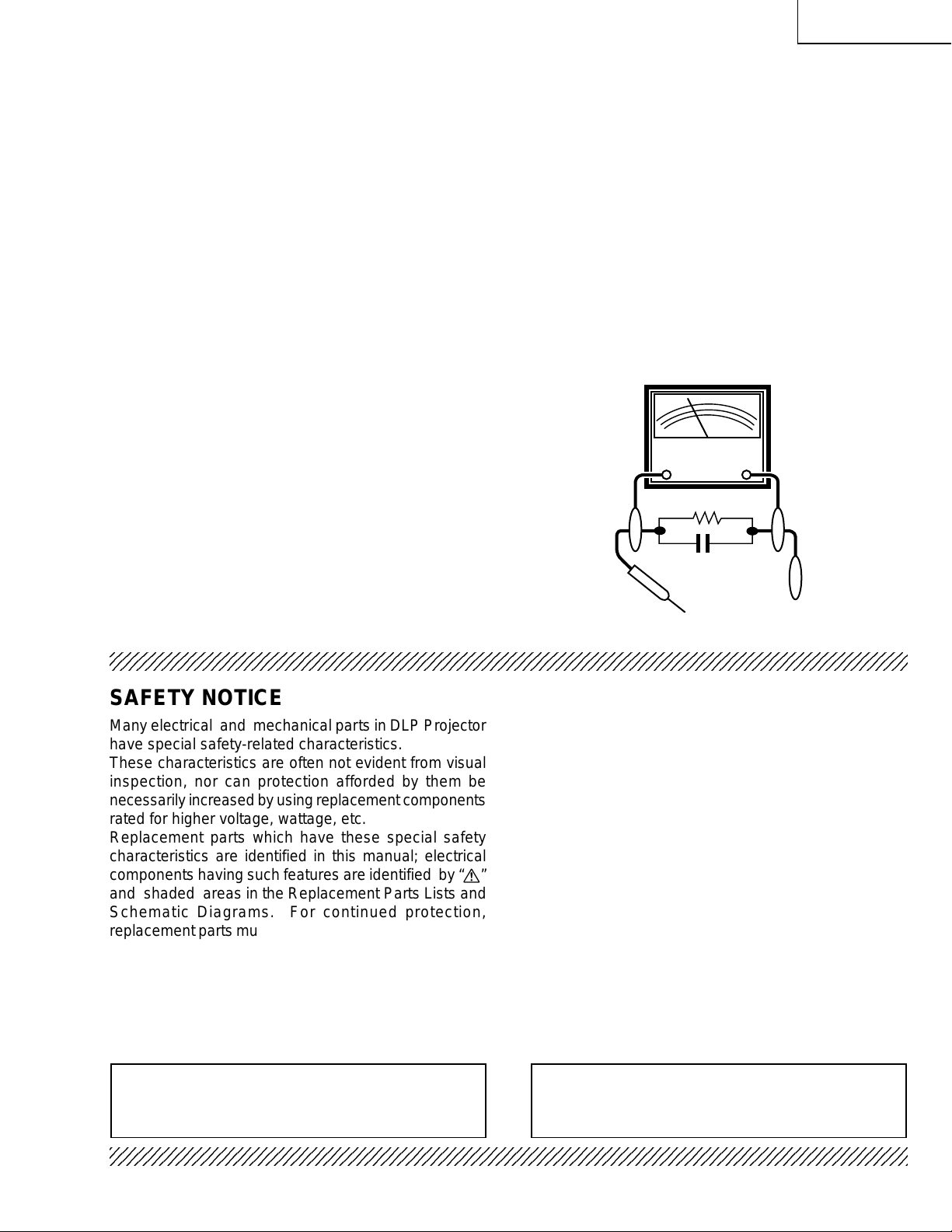
3. To be sure that no shock hazard exists, check for
current leakage in the following manner:
» Plug the AC cord directly into a 120-volt AC outlet,
(Do not use an isolation transformer for this test).
» Using two clip leads, connect a 1.5k ohm, 10 watt
resistor paralleled by a 0.15µF capacitor in parallel
between all exposed metal cabinet parts and earth
ground.
» Use an AC voltmeter with sensitivity of 5000 ohm per
volt., or higher , sensitivity to measure the AC voltage
drop across the resistor (See Diagram).
» All checks must be repeated with the AC plug
connection reversed. (If necessary, a non-polarized
adapter plug must be used only for the purpose of
completing these checks.)
Any reading of 0.3 volts RMS (this corresponds to
0.2 milliamp. A C.) or more is e xcessive and indicates
a potential shock hazard which must be corrected
before returning the unit to the owner.
AC
VOLTMETER
1.5k ohm (10W)
0.15µF
TEST PROBE
TO EXPOSED
METAL PARTS
CONNECT TO KNOWN
EARTH GROUND
234567890123456789012345678901212345678901234567890123456789012123456789012345678901234567890121
SAFETY NOTICE
Many electrical and mechanical parts in DLP Projector
have special safety-related characteristics.
These characteristics are often not evident from visual
inspection, nor can protection afforded by them be
necessarily increased by using replacement components
rated for higher voltage, wattage, etc.
Replacement parts which have these special safety
characteristics are identified in this manual; electrical
components having such features are identified by “å”
and shaded areas in the Replacement Parts Lists and
Schematic Diagrams. For continued protection,
replacement parts must be identical to those used in the
original circuit. The use of a substitute replacement parts
which do not have the same safety characteristics as
the factory recommended replacement parts shown in
this service manual, may create shock, fire or other
hazards.
AVIS POUR LA SECURITE
De nombreuses pièces, électriques et mécaniques, dans
les projecteur à DLP présentent des caractéristiques
spéciales relatives à la sécurité, qui ne sont souvent
pas évidentes à vue.
Le degré de protection ne peut pas être nécessairement
augmentée en utilisant des pièces de remplacement
étalonnées pour haute tension, puissance, etc.
Les pièces de remplacement qui présentent ces
caractéristiques sont identifiées dans ce manuel;
les pièces électriques qui présentent ces particularités
sont identifiées par la marque “å” et hachurées dans la
liste des pièces de remplacement et les diagrammes
schématiques. Pour assurer la protection, ces pièces
doivent être identiques à celles utilisées dans le circuit
d’origine. L’utilisation de pièces qui n’ont pas les mêmes
caractéristiques que les pièces recommandées par
l’usine, indiquées dans ce manuel, peut provoquer des
électrocutions, incendies ou autres accidents.
WARNING: The bimetallic component has the primary
conductive side exposed. Be very careful in
handling this component when the power is on.
234567890123456789012345678901212345678901234567890123456789012123456789012345678901234567890121
AVERTISSEMENT:La composante bimétallique dispose du
conducteur primaire dénudé. Faire
attention lors de la manipulation de cette
composante sous tension.
3
Page 4
XG-NV7XU
NOTE TO SERVICE
PERSONNEL
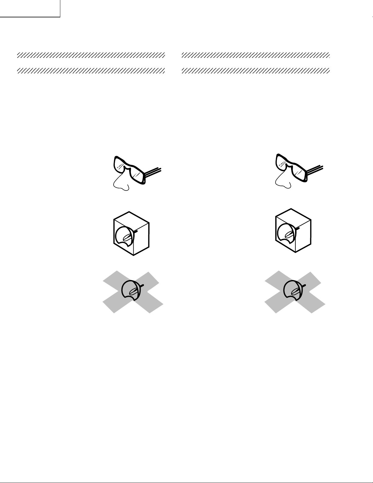
UV-RADIATION PRECAUTION
The light source, metal halide lamp, in the DLP
projector emits small amounts of UV-Radiation.
AVOID DIRECT EYE AND SKIN EXPOSURE.
To ensure safety please adhere to the following:
1. Be sure to wear sun-glasses when servicing the
projector with the lamp
turned “on” and the top
enclosure removed.
2. Do not operate the lamp outside of the lamp housing.
NOTE POUR LE PERSONNEL
D’ENTRETIEN
PRECAUTION POUR LES RADIATIONS UV
La source de lumière, la lampe métal halide, dans le
projecteur DLP émet de petites quantités de radiation
UV.
EVITEZ TOUTE EXPOSITION DIRECTE
DES YEUX ET DE LA PEAU.
Pour votre sécurité, nous vous prions de respecter
les points suivants:
1. Toujours porter des lunettes de soleil lors d’un
entretien du projecteur
avec la lampe allumée
et le haut du coffret retiré.
2. Ne pas faire fonctionner la lampe à l’extérieur du
boîtier de lampe.
3. Do not operate for more than 2 hours with the
enclosure removed.
UV-Radiation and Medium Pressure
Lamp Precautions
1. Be sure to disconnect the AC plug when replacing
the lamp.
2. Allow one hour for the unit to cool down before
servicing.
3. Replace only with same type lamp. Type
CLMPF0078DE01 or BQC-XGNV7XU/1 rated 85V/
120W.
4. The lamp emits small amounts of UV-Radiation, a void
direct-eye contact.
5. The medium pressure lamp involves a risk of
explosion. Be sure to follow installation instructions
described below and handle the lamp with care.
3. Ne pas faire fonctionner plus de 2 heures avec le
coffret retiré.
Précautions pour les radiations UV
et la lampe moyenne pression
1. Toujours débrancher la fiche AC lors du
remplacement de la lampe.
2. Laisser l’unité refroidir pendant une heure avant de
procéder à l’entretien.
3. Ne remplacer qu’avec une lampe du même type.
Type CLMPF0078DE01 or BQC-XGNV7XU/1,
caractéristique 85V/120W.
4. La lampe émet de petites quantités de radiation UVéviter tout contact direct avec les yeux.
5. La lampe moyenne pression implique un risque
d’explosion. Toujours suivre les instructions
d’installation décrites ci-dessous et manipuler la
lampe avec soin.
4
Page 5
XG-NV7XU
5
4
5
5
234567890123456789012345678901212345678901234
UV-RADIATION PRECAUTION (Continued)
23456789012345678901234567890121234567890123
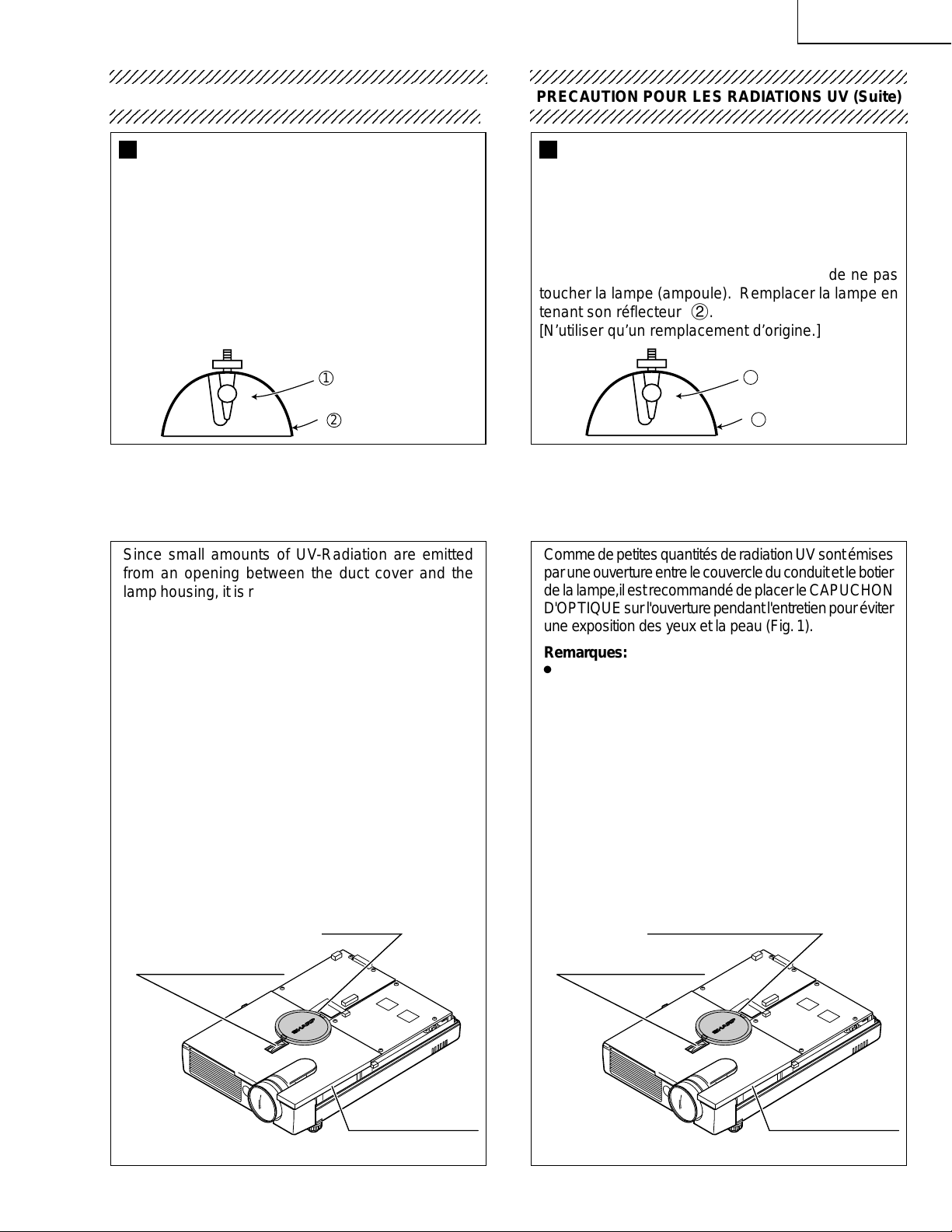
Lamp Replacement
Note:
Since the lamp reaches a very high temperature
during units operation replacement of the lamp
should be done at least one hour after the power
has been turned off. (to allow the lamp to cool off.)
Installing the new lamp, make sure not to touch the
lamp (bulb) replace the lamp by holding its reflector
2.
[Use original replacement only.]
Lamp
1
Reflector
2
DANGER ! –– Never turn the power on without the
lamp to avoid electric-shock or damage of the
devices since the stabilizer generates high voltages
at its start.
234567890123456789012345678901212345678901234
PRECAUTION POUR LES RADIATIONS UV (Suite)
234567890123456789012345678901212345678901234
Remplacement de la lampe
Remarque:
Comme la lampe devient très chaude pendant le
fonctionnement de l’unité, son remplacement ne doit
être effectué au moins une heure après avoir coupé
l’alimentation (pour permettre à la lampe de refroidir).
En installant la nouvelle lampe, s’assurer de ne pas
toucher la lampe (ampoule). Remplacer la lampe en
tenant son réflecteur 2.
[N’utiliser qu’un remplacement d’origine.]
1
Lampe
Reflecteur
2
DANGER ! –– Ne jamais mettre sous tension sans
la lampe pour éviter un choc électrique ou des
dommages des appareils car le stabilisateur génère
de hautes tensions à sa mise en route.
Since small amounts of UV-Radiation are emitted
from an opening between the duct cover and the
lamp housing, it is recommended to place the LENS
CAP on the opening during servicing to avoid eye
and skin exposure (Fig. 1).
Notes:
» The internal par ts of this model are cooled down
with the top panel tightly closed. If the power is
kept on for a long time with the top panel open, the
power may be turned off or the lamp may go out.
To avoid this during servicing, place the service
cover over the lamp and the cooling fan.
» Place the lens cap over the service cover.
» Please obtain a lens cap before servicing a model
XG-NV7XU that is received without one.
» The color wheel is running at high speed. Do not
touch it nor bring anything nearby.
COLOR WHEEL HOLE
Comme de petites quantités de radiation UV sont émises
par une ouverture entre le couvercle du conduit et le botier
de la lampe,il est recommandé de placer le CAPUCHON
D'OPTIQUE sur l'ouverture pendant l'entretien pour éviter
une exposition des yeux et la peau (Fig. 1).
Remarques:
» Les pièces internes de ce modèle sont refroidies av ec
le panneau supérieur hermétiquement fermé. S i
l'énergie électrique est maintenue pendant longtemps
avec le panneau supérieur laissé ouvert, l'énergie risque
de s'arrêter ou la lampe de s'éteindre. Pour éviter cela
lors d'un entretien, placer le couvercle de l'entretien sur
la lampe et le ventilateur de refoidissement.
» Placer le bouchon de l'objectif sur le couvercle de
l'entretien.
» Priére de se procurer un capuchon d'optique acant
d'entretien un modéle XG-NV7XU qui est livré sans.
» Le disque chromatique opère à une vitesse élevée. Ne
pas le toucher ni apporter quoi que ce soit à proximité.
CAPUCHON D'OPTIQUELENS CAP
ORIFCE DU DISQUE
CHROMATIQUE
SERVICE COVER
Figure 1. Figure 1.
(PCOVN0009CEKZ)
5
SERVICE COVER
(PCOVN0009CEKZ)
Page 6
XG-NV7XU
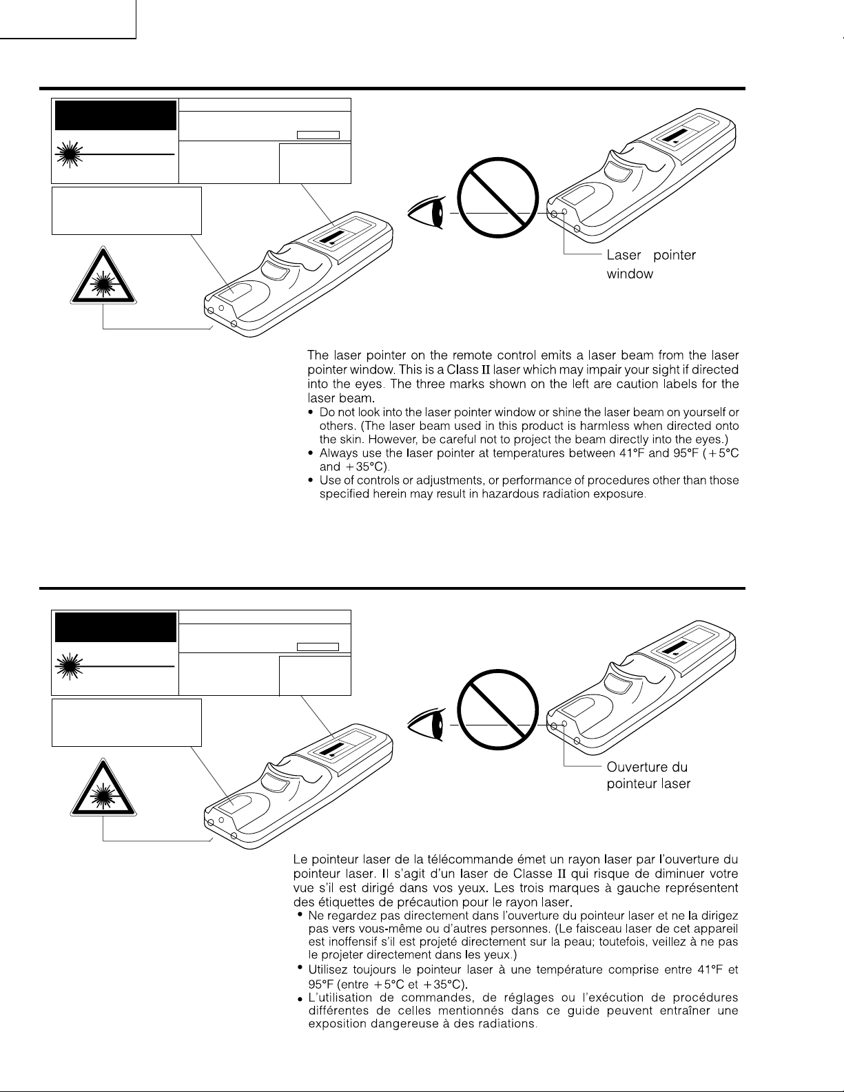
Cautions Concerning the Laser Pointer
"COMPLIES WITH 21 CFR SUBCHAPTER J"
CAUTION
LASER RADIATIONDO NOT STARE INTO BEAM
WAVE LENGTH : 650nm
MAX. OUTPUT : 1mW
CLASS II LASER PRODUCT
SHARP ELECTRONICS CORPORATION
SHARP PLAZA, MAHWAH, NEW JERSEY 07430
TEL : 1-800-BE-SHARP
REMOTE CONTROL
MODEL NO. : RRMCG1530CESA
DC3V (1.5VX2PCS.)
MADE IN CHINA
FABRIQU AU CHINE
U.S.A. ONLY
AVOID EXPOSURE
LASER
-
RADIATION IS EMITTED
FROM THIS APERTURE.
Précautions Liées au pointeur laser
"COMPLIES WITH 21 CFR SUBCHAPTER J"
CAUTION
LASER RADIATIONDO NOT STARE INTO BEAM
WAVE LENGTH : 650nm
MAX. OUTPUT : 1mW
CLASS II LASER PRODUCT
AVOID EXPOSURE
SHARP ELECTRONICS CORPORATION
SHARP PLAZA, MAHWAH, NEW JERSEY 07430
TEL : 1-800-BE-SHARP
REMOTE CONTROL
MODEL NO. : RRMCG1530CESA
DC3V (1.5VX2PCS.)
MADE IN CHINA
FABRIQU AU CHINE
LASER
-
RADIATION IS EMITTED
FROM THIS APERTURE.
U.S.A. ONLY
6
Page 7
XG-NV7XU
WARNING: High brightness light source. Do not stare into the beam of light, or view directly . Be especially
careful that children do not stare directly into the beam of light.
WARNING: To reduce the risk of fire or electric shock, do not expose this product to rain or moisture.
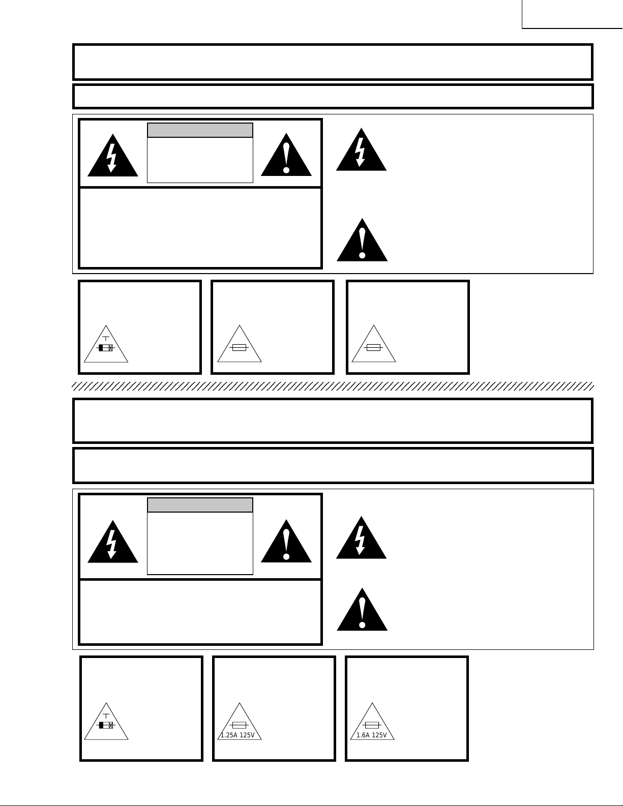
CAUTION
RISK OF ELECTRIC SHOCK.
DO NOT REMOVE SCREWS
EXCEPT SPECIFIED USER
SERVICE SCREW.
The lightning flash with arrowhead symbol,
within an equilateral triangle, is intended to
alert the user to the presence of uninsulated
“dangerous voltage” within the product’s
enclosure that may be of sufficient magnitude
to constitute a risk or electric shock to
CAUTION: TO REDUCE THE RISK OF ELECTRIC SHOCK,
DO NOT REMOVE COVER.
NO USER-SERVICEABLE PARTS EXCEPT LAMP UNIT.
REFER SERVICING TO QUALIFIED SERVICE
PERSONNEL.
persons.
The exclamation point within a triangle is
intended to alert the user to the presence of
important operating and maintenance
(servicing) instructions in the literature
accompanying the product.
CAUTION
(POWER Unit)
5A 250V
For continued
protection against
a risk of fire,
replace only with
same type and
rating of fuse.
(F1101)
CAUTION
(PC I/F Unit)
1.25A 125V
For continued
protection against
a risk of fire,
replace only with
same type
4511.25, Littelfuse
1.25A 125V.
CAUTION
(PC I/F Unit)
1.6A 125V
For continued
protection against
a risk of fire,
replace only with
same type
45101.6, Littelfuse
1.6A 125V.
A VERTISSEMENT: Source lumineuse de grande intensité. Ne pas fixer le faisceau lumineux ou le regar der
directement. V eiller particulièrement à éviter que les enfants ne fixent directement le
faisceau lumineux.
AVERTISSEMENT: Afin d’éviter tout risque d’incendie ou d’électrocution, ne pas exposer cet appareil à
la pluie ou à l’humidité.
ATTENTION
RISQUE
D’ELECTROCUTION. NE
PAS RETIRER LES VIS, A
L’EXCEPTION DES VIS DE
REPARATION UTILISATEUR
SPECIFIEES.
ATTENTION: POUR EVITER TOUT RISQUE
D’ELECTROCUTION, NE PAS RETIRER LE CAPOT.
AUCUNE DES PIECES INTERIEURES N’EST REPARABLE
PAR L’UTILISATEUR, A L’EXCEPTION DE L’UNITE DE LAMP.
POUR TOUTE REP ARATION, S’ADRESSER A UN
TECHNICIEN D’ENTRETIEN QUALIFIE.
PRECAUTION
(Unité d’alimentation)
5A 250V
Pour une protection
continue contre les
risques d’incendie,
ne remplacer
qu’avec un fusible
du même type.
(F1101)
PRECAUTION
(Unité d’interface PC)
1.25A 125V 1.6A 125V
Pour une protection
continue contre les
risques d’incendie,
ne remplacer
qu’avec un fusible
du même type
4511.25, miniature,
1.25A, 125V.
PRECAUTION
(Unité d’interface PC)
L’éclair terminé d’une flèche à l’intérieur
d’un triangle indique à l’utilisateur la
présence à l’intérieur de l’appareil d’une
«tension dangereuse» non isolée ayant
une amplitude suffisante pour provoquer
une électrocution.
Le point d’exclamation à l’intérieur d’un
triangle indique que des instructions de
fonctionnement et d’entretien importantes
sont détaillées dans les documents
fournis avec l’appareil.
Pour une protection
continue contre les
risques d’incendie,
ne remplacer
qu’avec un fusible
du même type
45101.6, miniature,
1.6A, 125V.
7
Page 8
XG-NV7XU
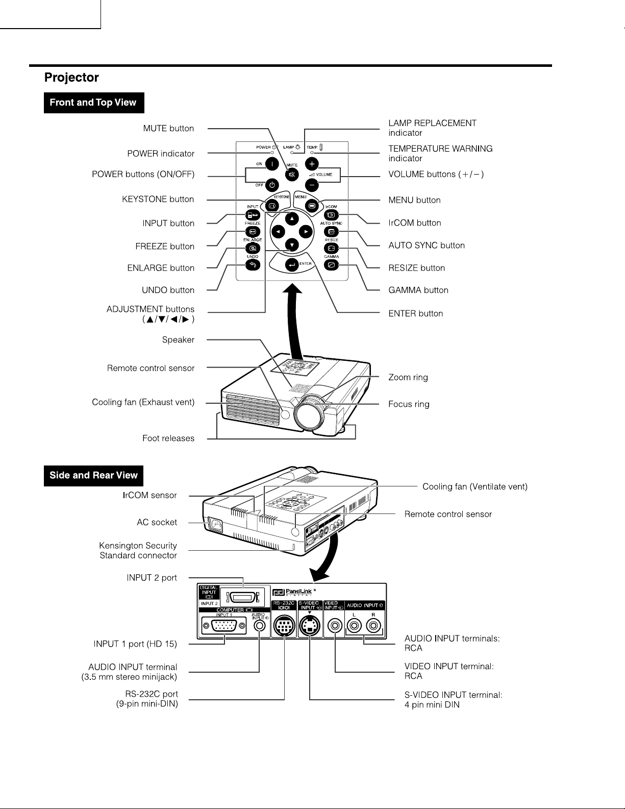
Location of Controls
8
Page 9
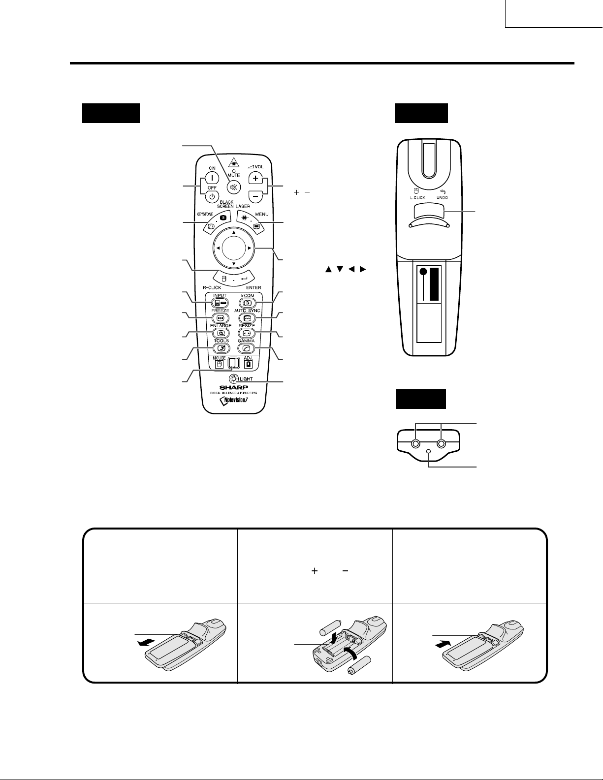
Operating the Wireless Mouse Remote Control
Remote Control
XG-NV7XU
Front View
MUTE button
POWER buttons
(ON/OFF)
KEYSTONE/BLACK
SCREEN button
RIGHT-CLICK/
ENTER button
FREEZE button
ADJUSTMENT
MOUSE/
switch
VOLUME buttons
(
/ )
LASER POINTER/
MENU button
MOUSE/
ADJUSTMENT
buttons
IrCOM buttonINPUT button
AUTO SYNC button
RESIZE buttonENLARGE button
GAMMA buttonTOOLS button
BACKLIGHT button
(///)
Rear View
LEFT-CLICK/
UNDO
button
T op View
Inserting the batteries
Press in and downward
on the arrow to remove
the battery cover.
Battery
cover
Remote control
signal transmitter
Laser
pointer
window
I
nsert two AA size batteries
213
for the remote control,
making sure their polarities
match the
and marks
inside the battery
Insert the side tabs of
the battery cover into
their slots and press the
cover in until it is
properly seated.
compartment.
Battery
Battery
compartment
cover
9
Page 10
XG-NV7XU
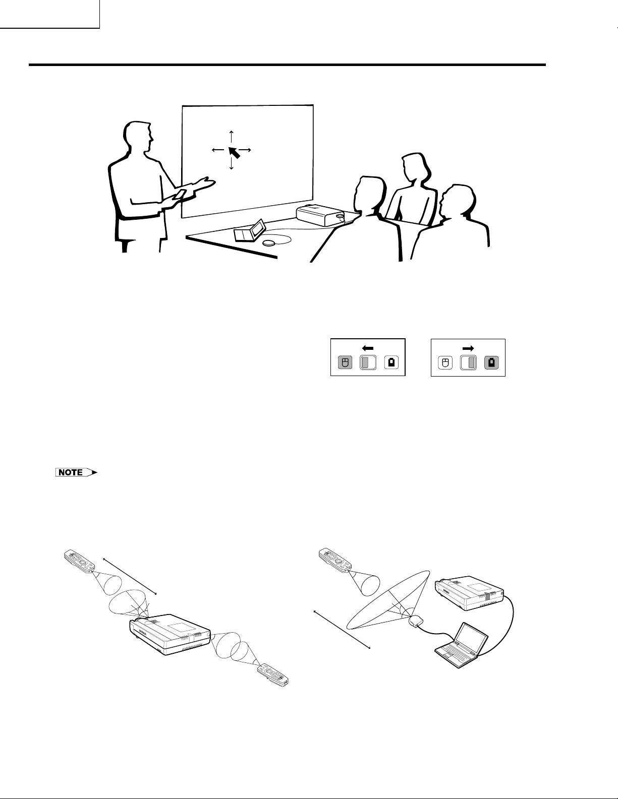
Using the Remote Control as a Wireless Mouse
The remote control has the following three functions:
• Projector control
MOUSE/ADJUSTMENT switch
(Remote control)
• Wireless mouse
• Laser pointer
MOUSE
ADJ.
Wireless mouse
Laser pointer
MOUSE
ADJ.
Projector control
Remote Control/Mouse Receiver Positioning
• The remote control can be used to control the projector within the ranges shown below.
• The remote mouse receiver can be used with the remote control to control the mouse functions of a connected
computer within the ranges shown below.
• The signal from the remote control can be reflected off a screen for easy operation. However, the effective distance of the
signal may differ due to the screen material.
Controlling the Projector
Remote control
23 (7 m)
30˚
45˚
30˚
Using the Wireless Mouse
Remote control
30˚
30˚
120˚
45˚
30˚
Remote control
10
13(4 m)
Remote
mouse
receiver
Page 11
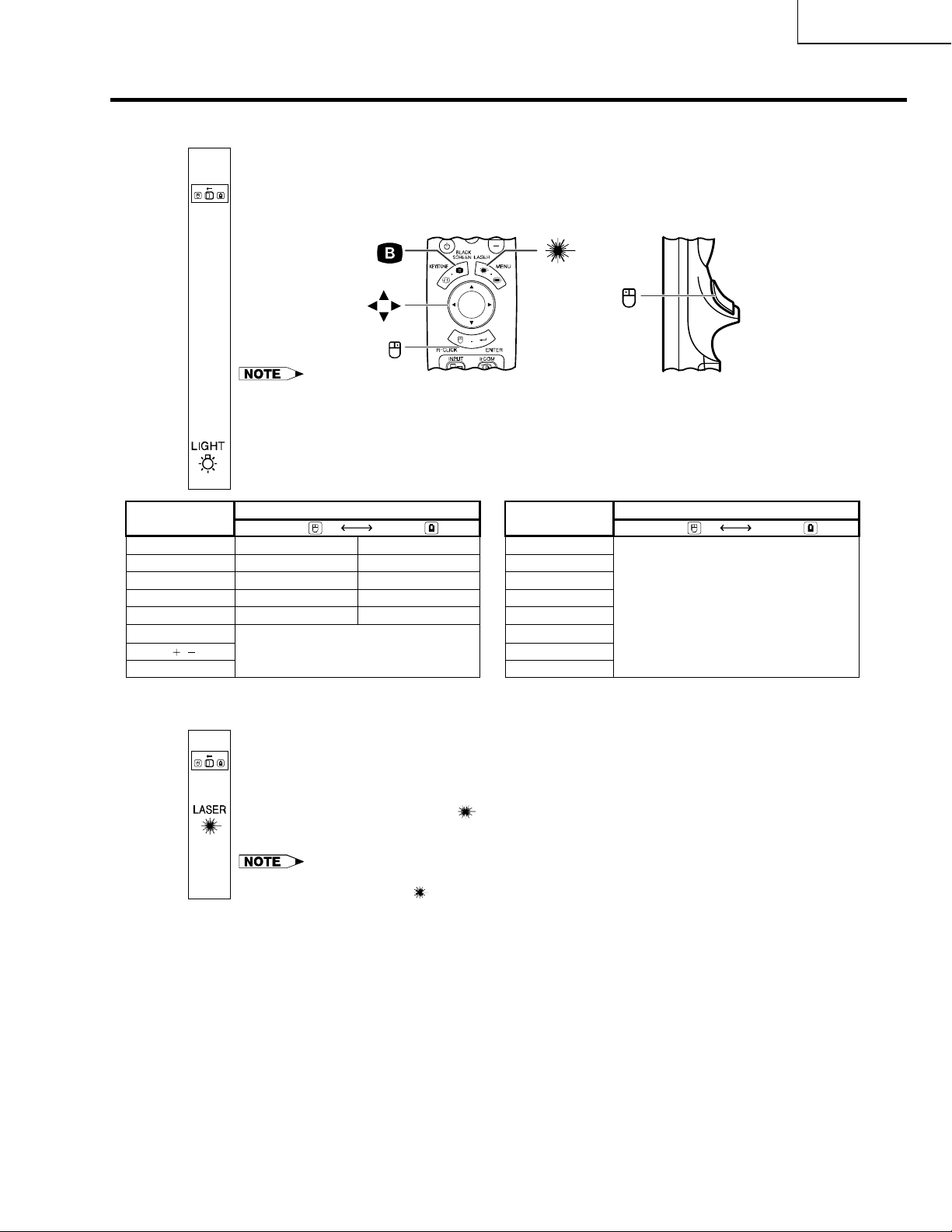
Use as a Wireless Mouse
Be sure the supplied remote mouse receiver is connected to your computer.
MOUSE
ADJ.
Slide the MOUSE/ADJUSTMENT switch to MOUSE.
1
Effective buttons in MOUSE mode
BLACK SCREEN
XG-NV7XU
LASER
POINTER
MOUSE
RIGHT-CLICK
¥ The wireless mouse may not operate correctly if your computer serial port is not correctly set up. Refer
to the computers operation manual for details of setting up/installing the mouse driver.
¥ For one-button mouse systems, use either the LEFT-CLICK or RIGHT-CLICK button.
Using the remote control in a dark room
Press BACKLIGHT, and the buttons will light up. Gr een lights refer to mouse operations, and red
lights to projector adjustments.
Button name
LASER POINTER/MENU
BLACK SCREEN/KEYSTONE
RIGHT-CLICK/ENTER
MOUSE/ADJUSTMENT
LEFT-CLICK/UNDO
POWER ON/OFF
VOLUME
MUTE
/
Position of MOUSE/ADJUSTMENT switch
MOUSE
LASER POINTER (GREEN)
BLACK SCREEN (GREEN)
RIGHT-CLICK (GREEN)
MOUSE (NOT LIT)
LEFT-CLICK (NOT LIT)
Use as a Laser pointer
ADJ.
MENU (RED)
KEYSTONE (RED)
ENTER (RED)
ADJUSTMENT (NOT LIT)
UNDO (NOT LIT)
ON (RED)
LEFT-CLICK
Button name
INPUT
IrCOM
FREEZE
AUTO SYNC
ENLARGE
RESIZE
TOOLS
GAMMA
Position of MOUSE/ADJUSTMENT switch
MOUSE ADJ.
ON (RED)
1
2
MOUSE
ADJ.
Slide the MOUSE/ADJUSTMENT switch to MOUSE.
Press LASER POINTER (
) to activate the laser pointer.
When the button is released, the light automatically goes off.
¥ For safety, the laser pointer automatically goes off after 1 minute of continuous use. To turn it on,
release LASER POINTER (
) and press again.
11
Page 12
XG-NV7XU
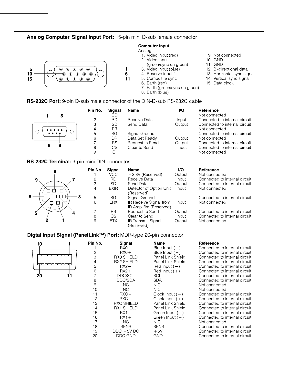
Connection Pin Assignments
12
Page 13
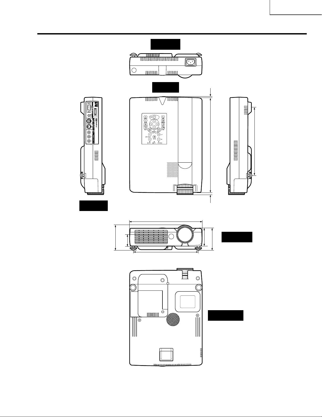
Dimensions
XG-NV7XU
Rear View
Side View
(82 )
64
/
15
3
(37.5)
32
/
15
1
T op View
9 1/4 (235)
11
/32 (212)
8
(58)
32
/
9
2
(1.2)
64
/
3
(312.5)
64
/
19
12
(8.1)
16
/
5
Front View
(71.5 )
16
/
13
2
(219)
8
/
5
8
13
Bottom View
Units: inches (mm)
Page 14
XG-NV7XU
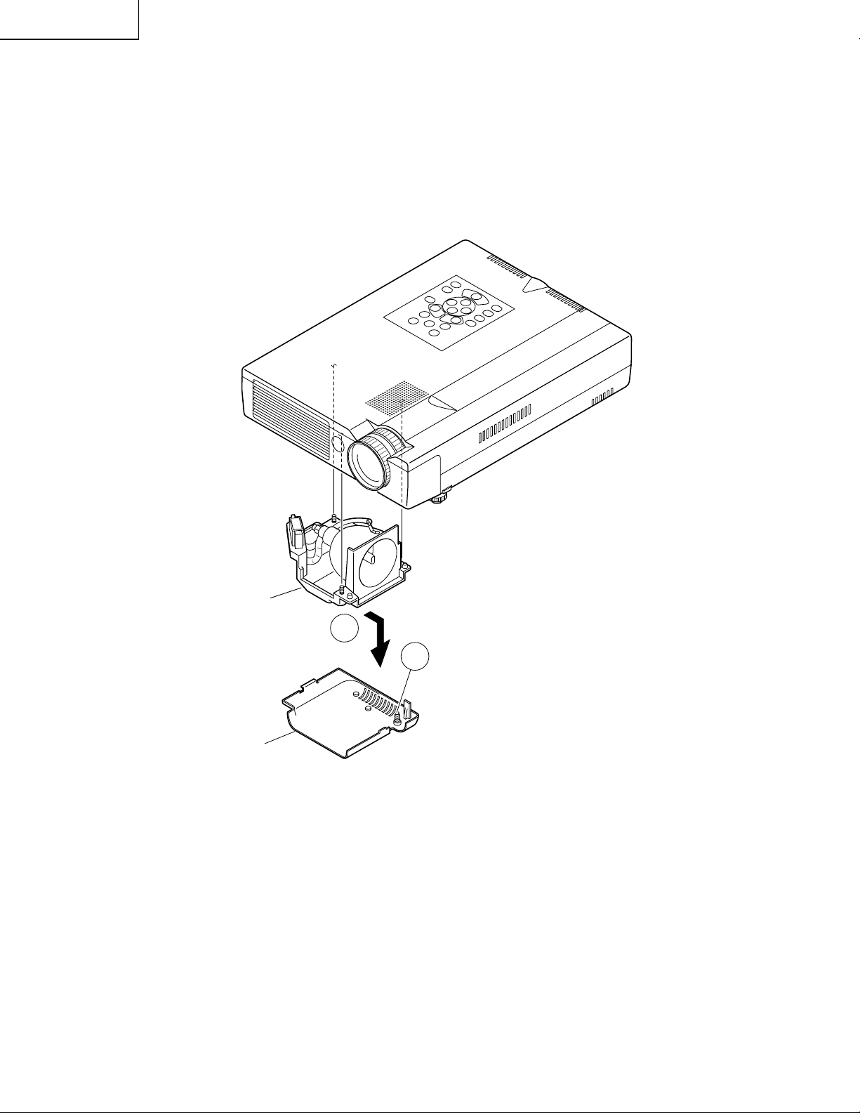
REMOVING OF MAJOR PARTS
1.Removing the Lamp Unit
1-1. Remove the screw from the lamp cover and detach the lamp cover.
1-2. Remove the three screws from the lamp unit and take out the lamp unit.
Lamp Unit
Lamp Cover
1-2
1-1
14
Page 15
XG-NV7XU
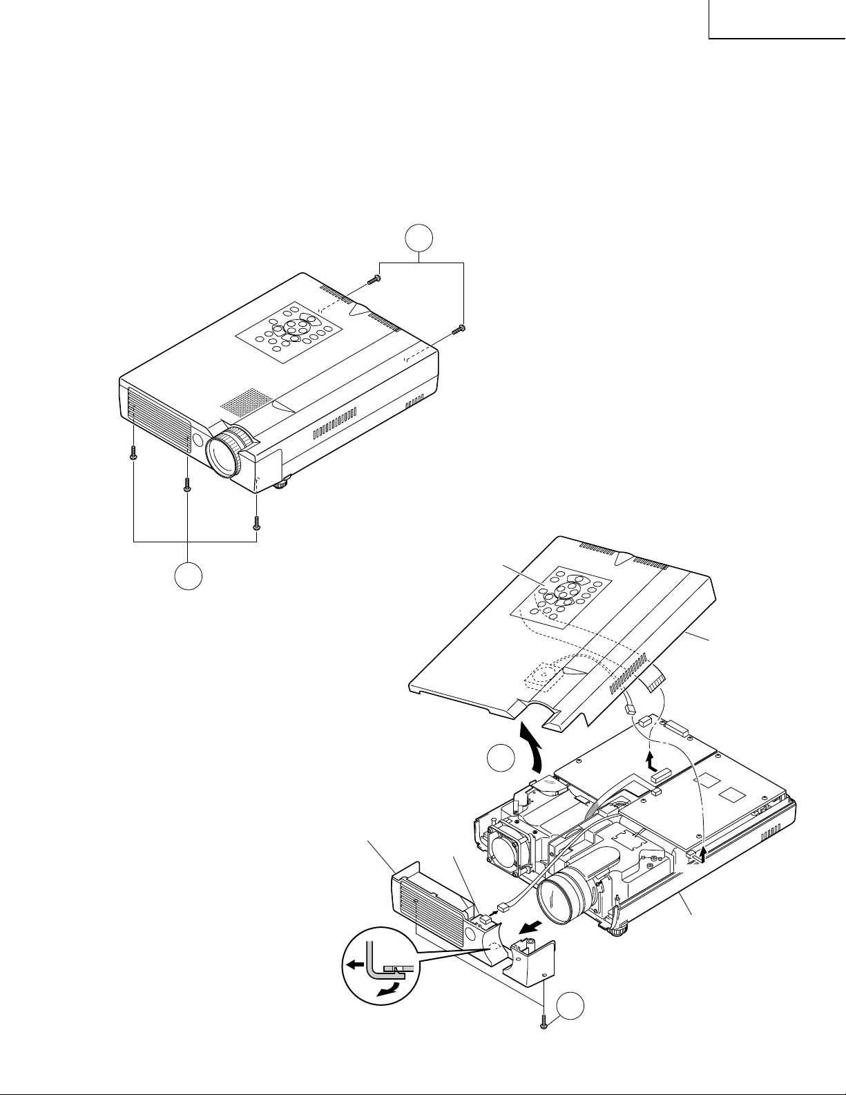
2.Removing the Top and Front Cabinets
2-1. Remove the two screws from the top and bottom cabinets.
2-2. Remove the three screws from the top and front cabinets.
2-3. Slowly lift the back of the top cabinet and disconnect the operation key unit connector (KY) and the speaker
connector (SP). Pull up and off the top cabinet.
2-4. Remove the two screws from the front cabinet and disconnect the remote control unit connector (RC). Unhook
the center of the front cabinet and take out the front cabinet.
2-1
2-2
Front Cabinet
Operation Key Unit
2-3
R/C Unit
(RC)
Top Cabinet
(KY)
(SP)
(SC)
(SP(P301))
Bottom Cabinet
15
2-4
Page 16
XG-NV7XU
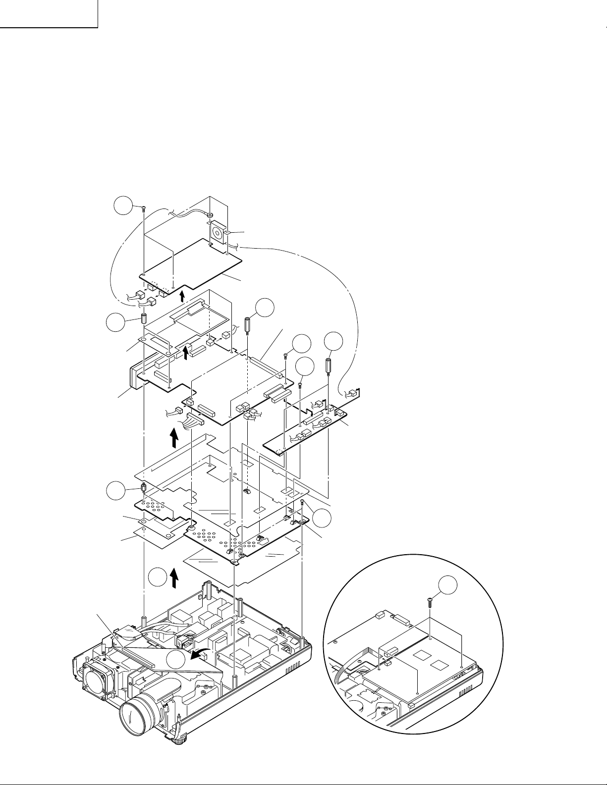
3-1
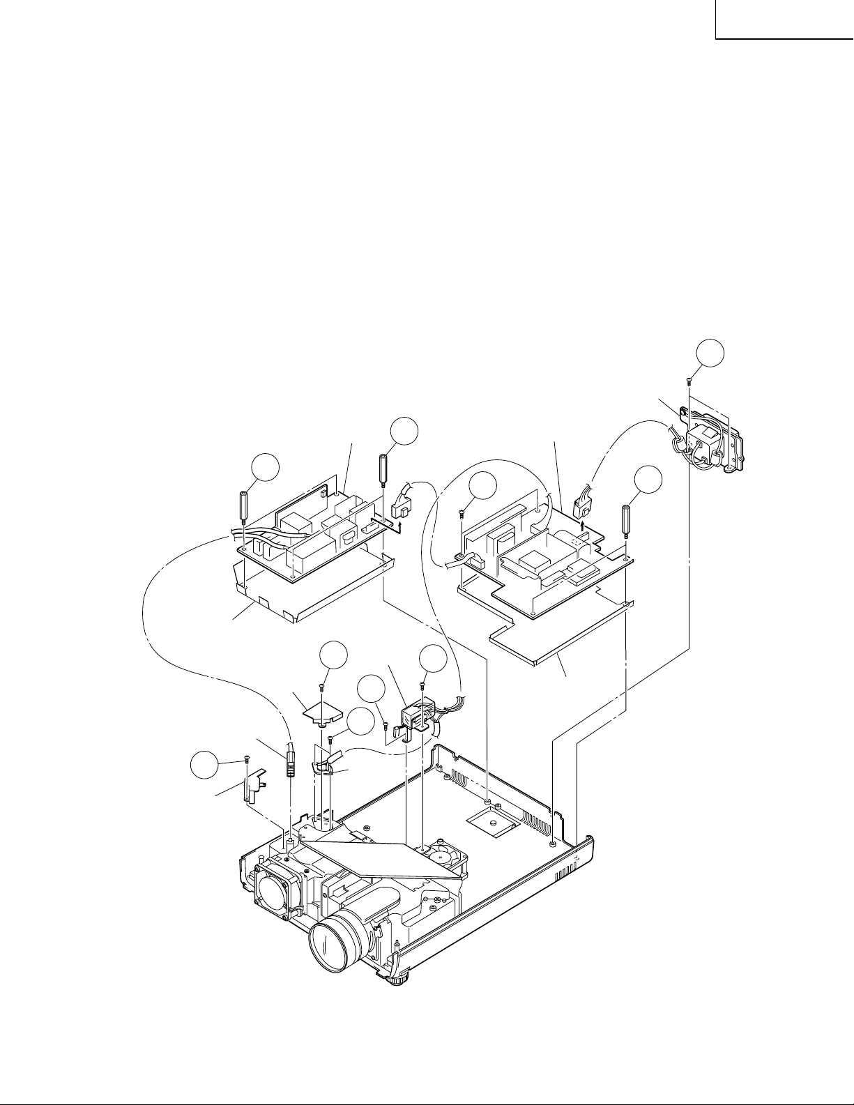
3.Removing the PWB Units
3-1. Remove the four screws from the output unit and disconnect the color wheel unit connector (J501).
3-2. Disconnect the output unit from the PC I/F unit connector. Tilt this unit toward the optical mechanism unit.
3-3. Remove the four screws from the main unit and detach the cooling fan (intake). Disconnect the S-out unit
connector (AU) and the temperature ensor connector (TI). Now take out the main unit.
3-4. Remove the two spacers, the screw and all the connectors from the S-out unit. Detach the S-out unit.
3-5. Remove the six spacers, the two screws and all the connectors from the PC I/F unit. Pull up and off the PC I/
F unit and the terminal unit together.
3-6. Detach the insulation barrier from the PC I/F unit.
3-7. Remove the four spacers and the two screws from the shielded board. Detach the shielded board.
3-8. Detach the insulation barrier from the power/ballast unit.
3-3
Cooling Fan (Intake)
3-5
Shield-1
Terminal Unit
3-7
Shield-2
Insulation Barrier
(AU)
Main Unit
(TI)
3-5
(P8503)
PC I/F Unit
3-5
3-4
(FE)
(AU)
(SP)
3-4
(FB)
(FA)
(FC)
S-Out Unit
(DB)
(PA)
(DC)
(RC)
(PB)
Insulation Barrier
3-7
Shield Board
Output Unit
3-8
3-2
(J501)
16
Page 17
XG-NV7XU
4.Removing the Power/Ballast Unit
4-1. Remove the two lock screws off the Inlet Ass’y.
4-2. Remove the screw from the bimetal cover and detach this cover
4-3. Remove the two screws from the bimetal assembly and detach this assembly.
4-4. Remove the two screws from the AC power switch and detach this switch.
4-5. Remove the two spacers, the two screws and all the connectors from the power unit. Detach the power unit
and the insulation barrier.
4-6. Remove the screw from the lamp socket holder and detach the lamp socket.
4-7. Remove the four spacers from the ballast unit. Detach the ballast unit and the insulation barrier.
<DMD handling precautions>
Be very careful never to bend and twist the flexible cable.
To protect the parts from static electricity, be sure to wear an earth band when handling them.
4-1
Inlet Ass’y
Insulation Barrier
(Ballast Unit)
Lamp Socket
4-6
Socket Holder
4-7
Bimetal
Cover
Ballast Unit
AC Power
4-2
Switch
4-4
4-3
Bimetal
Ass’y
4-7
4-4
(CN105)
Power Unit
4-5
Insulation Barrier
(Power Unit)
(CN102)
4-5
(CN101)
17
Page 18
XG-NV7XU
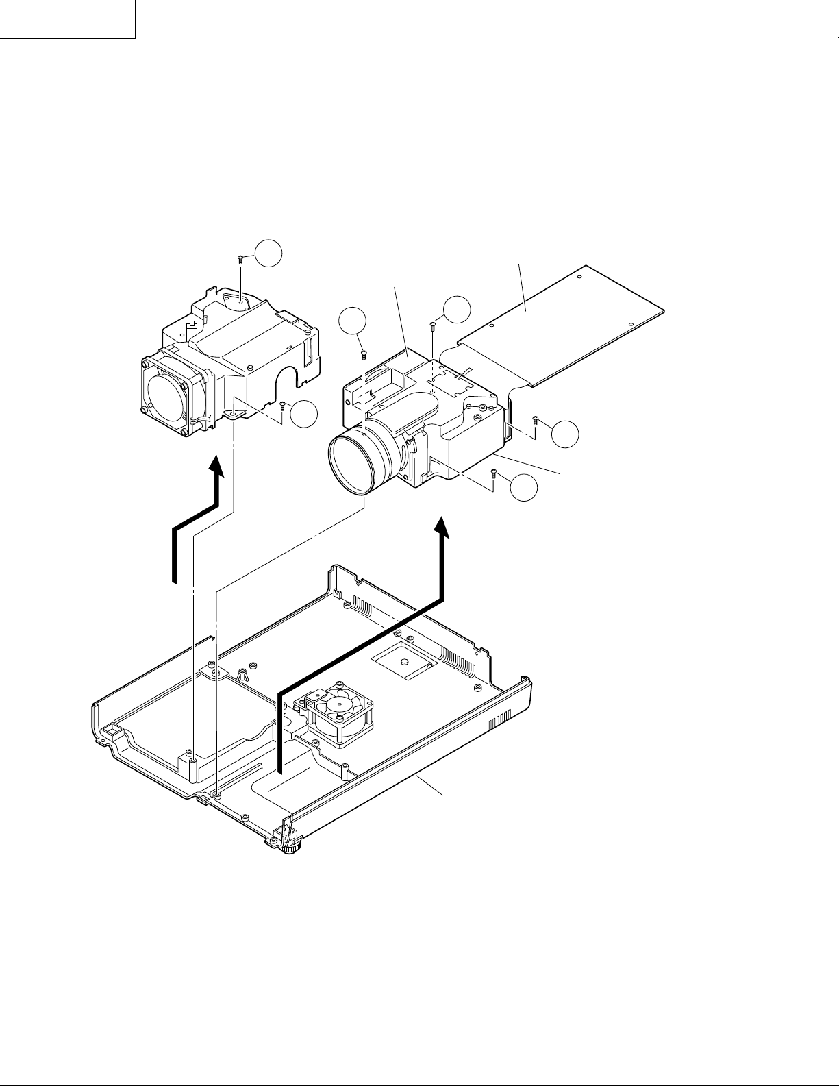
5.Removing the Optical Mechanism and Lamp Housing
5-1. Remove the two screws from the lamp housing and detach the housing.
5-2. Remove the four screws from the optical mechanism unit and detach this unit.
`: When removing these screws, be careful not to damage the capacitors nearby.
5-1
5-1
Color Wheel Unit
5-2
`
5-2
Output Unit
`
5-2
5-2
Optical Mechanism
Unit
18
Bottom Cabinet
Page 19
XG-NV7XU
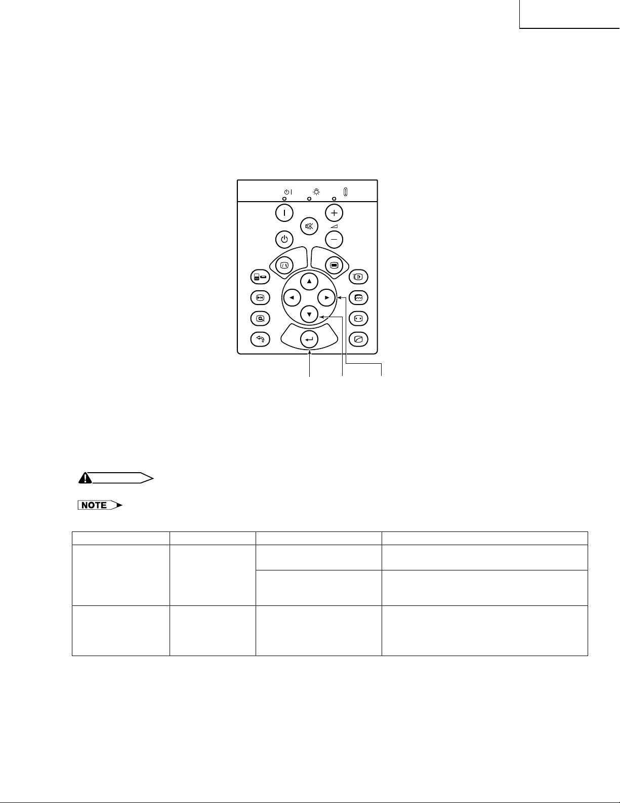
RESETTING THE T OTAL LAMP TIMER
When the lamp has been replaced, reset the total lamp timer in the following steps.
Resetting procedure
1. While holding down the “ENTER”, “ADJ."” and “ADJ.|” keys on the set at the same time, turn on the POWER
ON key.
2. Now the total lamp timer is reset to zero. “0000H” appears on the screen.
INPUT
FREEZE
UNDO
POWER
ON
OFF
LAMP
ENTER ADJ." ADJ.|
MUTE
MENULENS
ENTER
TEMP.
VOLUME
IrCOM
AUTO SYNC
RESIZEENLARGE
GAMMA
Lamp
The lamp in this projector operates for approximately 1,500 cumulative hours, depending on the usage environment. It is recommended that the lamp be replaced after 1,400 cumulative hours of ues or when you notice a
significant deterioration of the picture and color quality. The lamp usage time can be checked with the On-screen
Display.
CAUTION
» Intense light hazard. Do not attempt to look into the aperture and lens while the projector is operating.
» As the usage environment can vary significantly, the projector lamp may not operate for 1,500 hours.
Maintenance Indicator
TEMPERATURE
WARNING indicator
The internal
temperature is
abnormally high.
Condition
Problem
· Blocked air intake.
· Cooling fan breakdown.
· Internal circuit failure.
· Relocate the projector to an area with
proper ventilation.
· Take the projector to your nearest Authorized Sharp Industrial DLP Products
Possible Solution
Dealer or Service Center for repair.
LAMP REPLACEMENT indicator
The lamp does
not light up.
· Burnt-out lamp.
· Lamp circuit failure.
· Carefully replace the lamp.
· Take the projector to your nearest Au-
thorized Sharp Industrial DLP Products
Dealer or Service Center for repair.
19
Page 20
XG-NV7XU
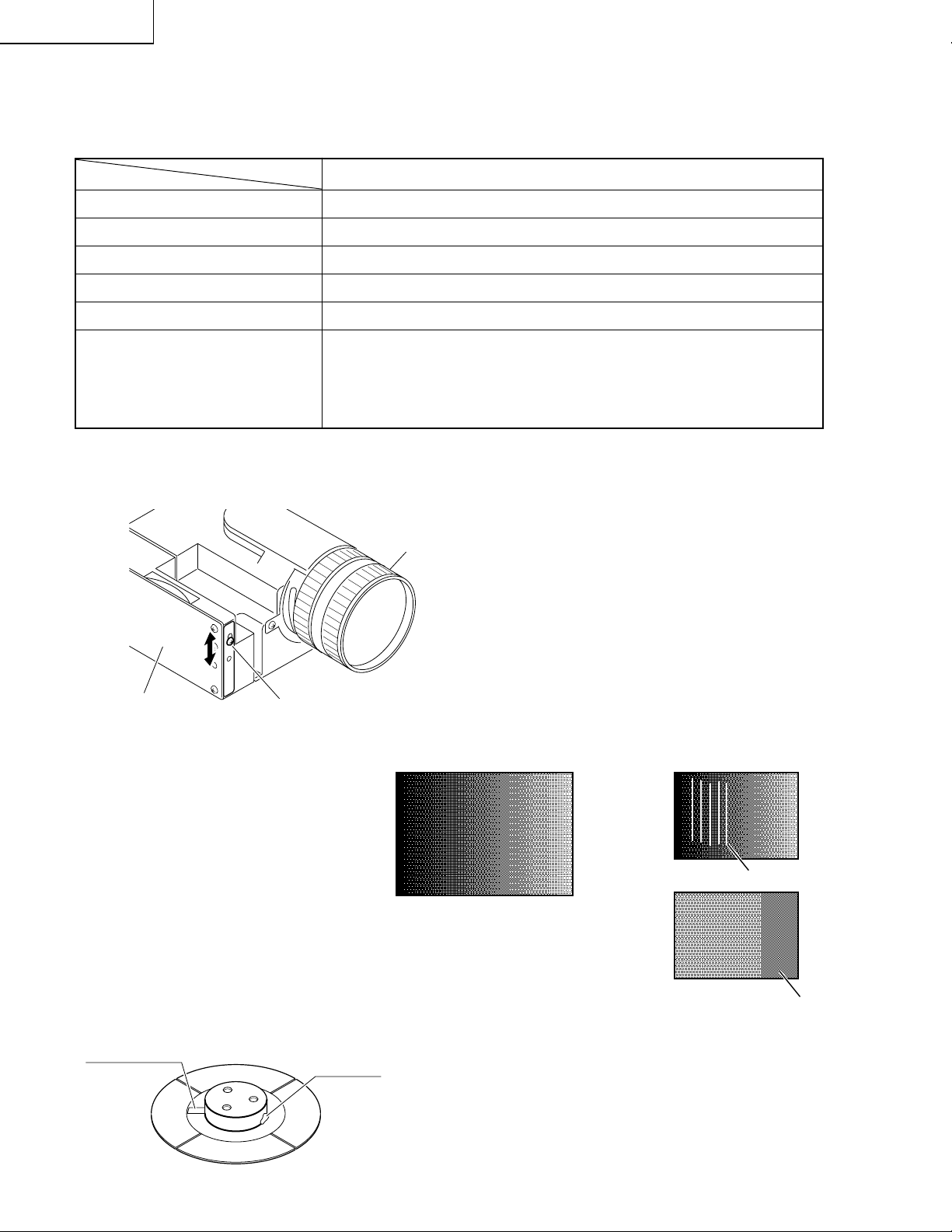
OPTICAL ADJUSTMENT
What to readjust after replacement
Readjustment
Reflection lens
Cylinder mirror
Mirror A
Mirror B
Requirements for adjustments
Color wheel
Not needed.
Not needed.
Not needed.
Not needed.
Phillips screwdriver, red gradation pattern signal.
Enter the red gradation pattern from RGB1. Make sure the pattern
appears normal on screen.
If not, loosen the wheel sensor screw and move the sensor up and
down until the gradation appears crisp on screen. (White lines and
magenta portions are not allowed.)
Adjustment after color wheel replacement
Lens
Color Wheel
Note: Never peel off the sensing seal and
balancer from around the motor.
Sensing Seal
Wheel Sensor Screw
Balancer
Normal Unacceptable
Black RedBlack
Gradation pattern
Red
White lines
RedRed
Magenta
20
Page 21
DMD AND PRINCIPLE OF OPTICAL SYSTEM
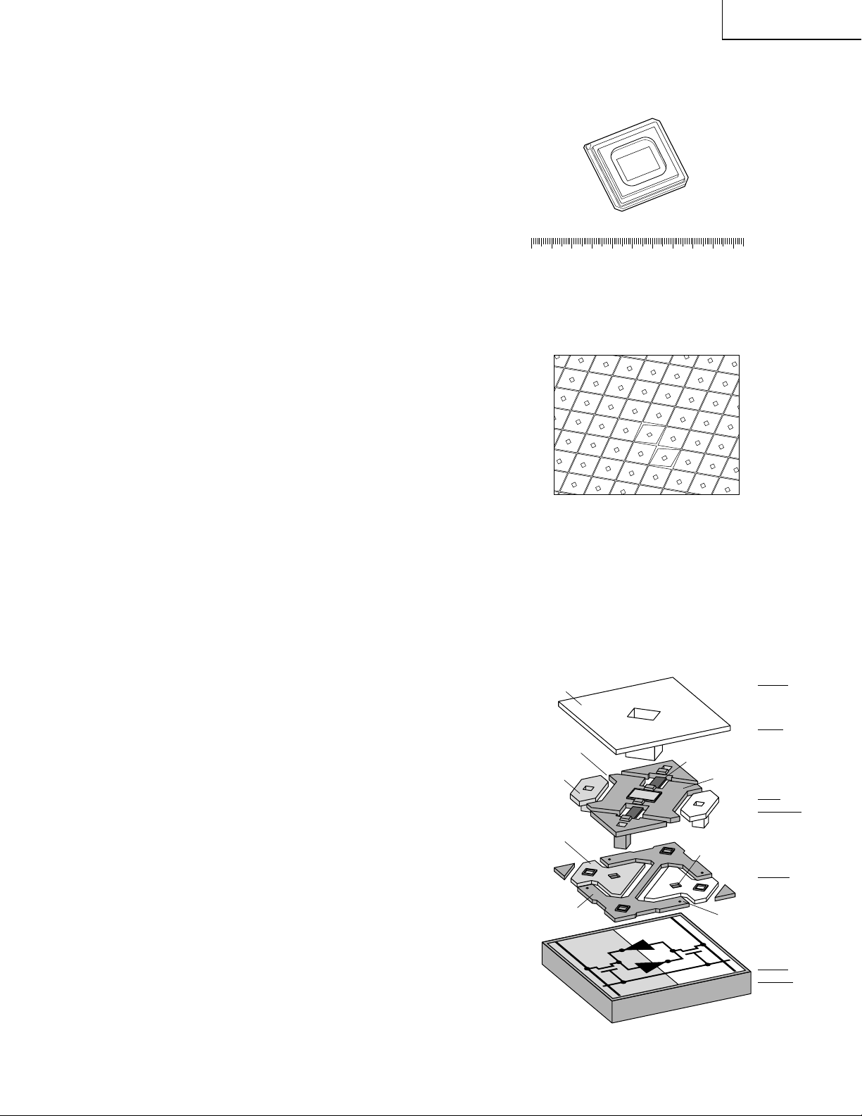
1.Outline of DMD
(Digital Micro Mirror Device)
The DMD is one of the ultra-micro electromechanical
systems called MEMS (Microeletromechanical System).
The DMD can be fabricated by employing the existing
0.8 micron rule, which is the established semiconduc-
tor manufacturing technology.
The DMD is an optical switch of semiconductor chip
fabricated by connecting several hundred thousand to
one million and several hundred thousand mirrors
(16µm X 16µm in size) onto the CMOS SRAM
semiconductor memory and these mirrors rotate
mechanically when digital electric signal is received.
In the DMD, the mirror rotates at an angle of ±10
degrees by the action of electrostatic field produced by
voltage which is generated on the SRAM memory . The
rotation of this mirror changes the direction of reflected
light, the principle of which is applied for the optical
switch. The gray scale (or color gradation) of reflected
light is achieved by controlling the response time (or
ON-time) of the mirror with digital signal (8-bit pulse
width modulation [PWM] signal) (Processing with 10bit PWM signal is now also available).
The gray scale has 256 tones. Hence, the total nµmber
of tones for RGB full primary colors counts as many as
256 X 256 X 256 = 16,700,000.
XG-NV7XU
2 3 4 5 6 7 8 9 10 11 12
About 500,000 micro mirrors are found at the
central white part.
Figure 1. DMD (SVGA Specification)
Mirrors (each one of squares).
Area of a mirror is 16 µm X 16 µm. The space
between adjacent mirrors is 1 µm.
Figure 2. Microscopic View of DMD
2.Structure of DMD Pixel
Figure 3.
The DMD monolithically consists of the four layers;
mirror, yoke and hinge, metal-3, and CMOS memory.
The mirror is made of 16 µm X 16 µm alµminµm plate.
The mirror is rigidly connected to the yoke below. The
yoke, in turn, is connected by two thin mechanically
compliant torsion hinges to the posts that are attached
to the PWB below . The address electrodes for the mirror
and yoke are connected to the complementary sides
of the PWB below . The yoke and mirror are connected
to the bias-reset bus formed on the metal-3 layer. The
bias-reset bus interconnects the yoke and mirrors of
each pixel to the bond pad around the chip.
When the digital signals [1] and [0] are written on the
CMOS SRAM, the mirror supported by the posts
inclines diagonally toward the PWB side. The angle of
inclination is ±10 degrees.
* DMD and DLP are the trademarks of Texas Instruments, Inc., U.S.A.
shows an exploded view of the DMD pixel.
Mirror
Landing Tip
Mirror
Address
Electrode
Yoke
Address
Electrode
Bias-Reset
Bus
Torsion Hinge
Yoke
Via 2 Contact
to CMOS
Landing
Site
Figure 3. DMD pixel exploded view
(Layers)
Mirror
Yoke
and Hinge
Metal-3
CMOS
Memory
21
Page 22
XG-NV7XU
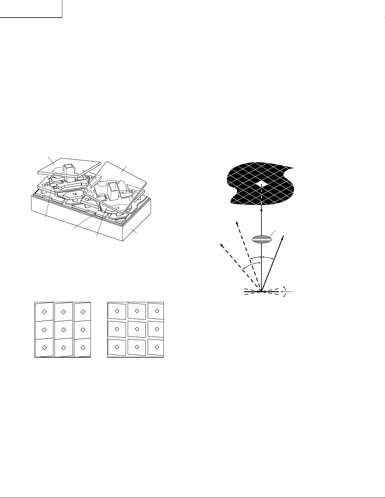
3.Switching of Mirror
The mirror reflects light in one of two directions,
depending of the state of underlying memory cell. The
mirror rotates by a force of electrostatic attraction
produced by voltage diff erence betw een the mirror and
the memory cell. With the memory cell being in the ON
(1) state, the mirror rotates by +10 degrees. With the
memory cell being in the OFF (0) state, the mirror rotates
by -10 degrees.
mirrors operating.
Mirror – 10 deg
Figure 5.
shows a close-up of DMD
Mirror + 10 deg
By combining the DMD with a suitable light source and
projection optics (
Figure 6.
), the mirror reflects incident
light either into or out of the center of the projection lens
by a simple beam steering technique. Thus , the (1) state
of the mirror appears bright and the (0) state of the mirror
appears dark.
Pixel
Image
Hing
Yoke
Landing Tip
Figure 4. Two DMD pixels
(mirrors are shown as transparent)
Figure 5. Images of operating DMD
CMOS
Substrate
+10°
Flat
–10°
40°
20°
Pixel
Mirror
Projection
Lens
Light From
Illuminator
20°
–10°
Flat
+10°
Figure 6. DMD optical switching principle
22
Page 23
GRB
1
23
4
56
7
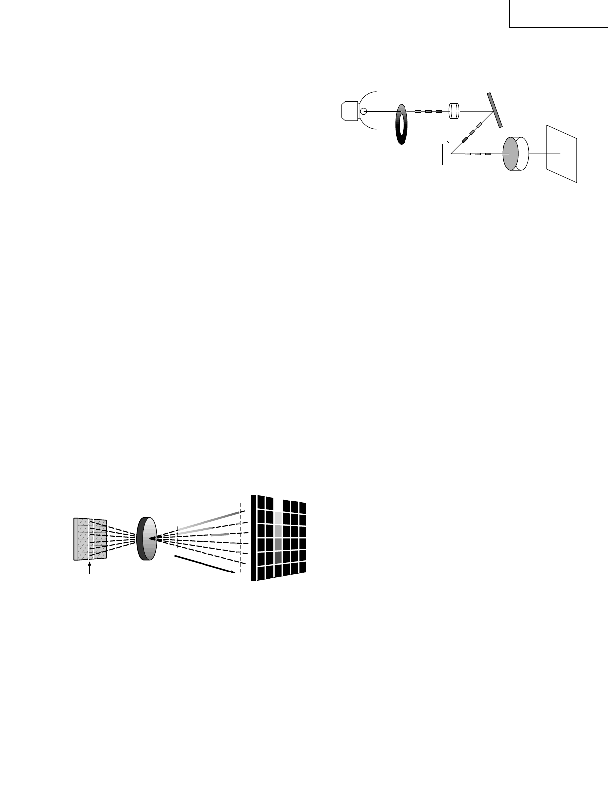
4.Digital Light Processing Signal and
Gray Scale
When the mirror rotates, it reflects incident light either
into or out of the projection lens to create a burst of
digital light pulses, which the eye interprets as an analog
image.
In binary pulse width modulation, the DMD accepts
electrical words representing the gray level of brightness at its input, and puts out optical words, which are
interpreted by the observer’s eye as analog brightness
level.
Taking 4-bit word as an example for simplicity, each bit
in the word represents a time duration for light to be ON
or OFF, and the time durations have relative value of
2°0, 211, 222 and 233 or 1, 2, 4 and 8 (
The video field time is divided into four time durations
of 1/15, 2/15, 4/15 and 8/15, and 24 or 16 equally spaced
gray le vels (0, 1/15, 2/15, 4/15, …, 15/15) are produced
by all the combinations of bits in the 4-bit word.
Currently available DLP systems are of either 24-bit color
(8 bits or 256 gray levels per RGB) or 39-bit color (10
bits or 1024 gray levels per RGB).
In the DLP displays of pulse width modulation, “bitsplitting technology” is combined to produce a “trueanalog” sensation with greater accuracy and stability
than can be achieved by analog projection systems.
Projection Lens
Video Field TIme
(1111)
(1001)
(0100)
(0010)
(0001)
(0000)
(Note: For simplicity, only central colµmn is addressed
(4-Bit Example)
and no light source is shown.)
Figure 7. DMD binary pulsewidth modulation
(4bit example)
Figure 7.
(Sensation of Gray Scale
by Viewer’s Eye)
).
XG-NV7XU
Figure 7. Bloc k Diagram of Optical System Principle
Names of Parts and Operating
Specifications
1 Metal Halide Lamp
The DC light source lamp flickers 180 times or 210
times per second
2 RGB Color Filter (Color Wheel Unit)
This color filter splits light into RGB primary colors.
The rotation-detecting sensor should be synchronized with the timing to turn off the lamp at the seam
of color filter. The maximµm rotating speed is 7200
rpm.
3 Condenser Lens
This lens condenses the light split by the color filter
and projects it to the effective area of the reflection
mirror.
4 Reflection Mirror
This mirror reflects the light projected to the effective
area of the DMD.
5 DMD Chip
This chip turns on and off in proportion to each
color element per dot depending on the input source.
6 Projection Lens
This lens magnifies and projects the incident light
coming from the DMD.
7 Screen
Projected light (RGB components) is interpreted by
viewer’s eye as a synthesized color image due to
after-image phenomenon.
* On the main PWB, the color components are split
per dot depending on the input source, and the
information is sent to the DMD.
23
Page 24

XG-NV7XU
ELECTRICAL ADJUSTMENT
Hook up a signal generator, or a DOSV or Mac personal computer to the projector in order to feed the
signals specified in the Adjusting conditions.
No. Adjusting point Adjusting conditions Adjusting procedure
1 EEPROM
initialization
1. Turn on the power (make
sure the lamp lights up) and
warm up the unit for 15 minutes.
» Make the following settings:
Press S5001 to call up the process mode and
execute S2 in the SSS menu. Now the system,
with the PC board not included, is initialized. Do
not execute S1 because otherwise the PC board
will be initialized.
To adjust the PC board, follow the instruction in
"Adjusting the PC Interface". (See page 30)
2 RGB1 BRIGHT 1. Make the following choice.
Group : A/D
Subject : BRIGHT
Make sure the data value is
125.
2. Make the following choice.
Group : A/D
Subject : R-BRIGHT,
G-BRIGHT,
B-BRIGHT
Adjust until the data value
becomes 135 or so.
3 R drive 1. Make the following choice.
Group : A/D
Subject : GAIN
2. F eed the 100% red-only signal. Make the following
choice.
Group : A/D
Subject : R-D
» With the set's control switch or the remote-control
button, adjust the data until the black-side noise
becomes bitless.
» Using the control switches or the remote controller
buttons, adjust the data so that the signal becomes bit-less (noise).
4 B drive 1. Feed the 100% blue-only
signal. Make the following
choice.
Group : A/D
Subject : B-D
5 G drive 1. Feed the 100% green-only
signal. Make the following
choice.
Group : A/D
Subject : G-D
» Using the control switches or the remote controller
buttons, adjust the data so that the signal becomes bit-less (noise).
» Using the control switches or the remote controller
buttons, adjust the data so that the signal becomes bit-less (noise).
24
Page 25
No. Adjusting point Adjusting conditions Adjusting procedure
XG-NV7XU
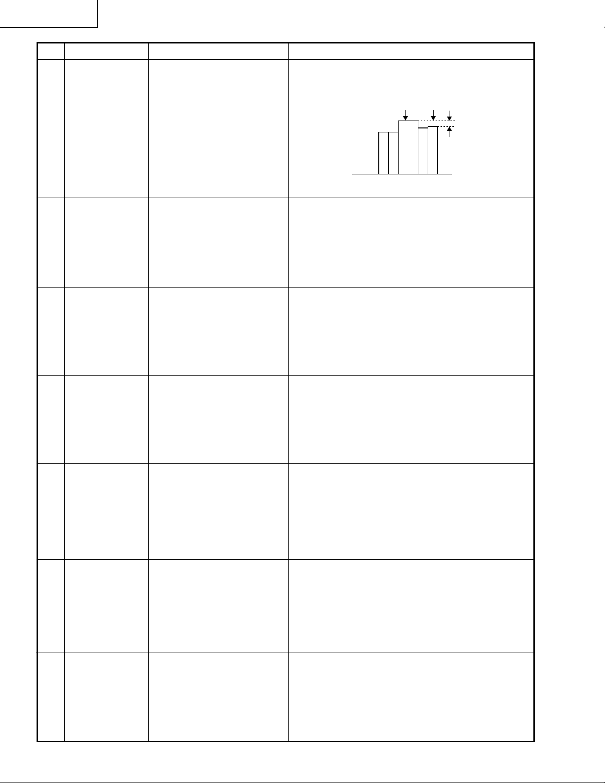
6 Gain adjustment 1. Make the following choice.
Group : A/D
Subject : GAIN
Initial value : 137
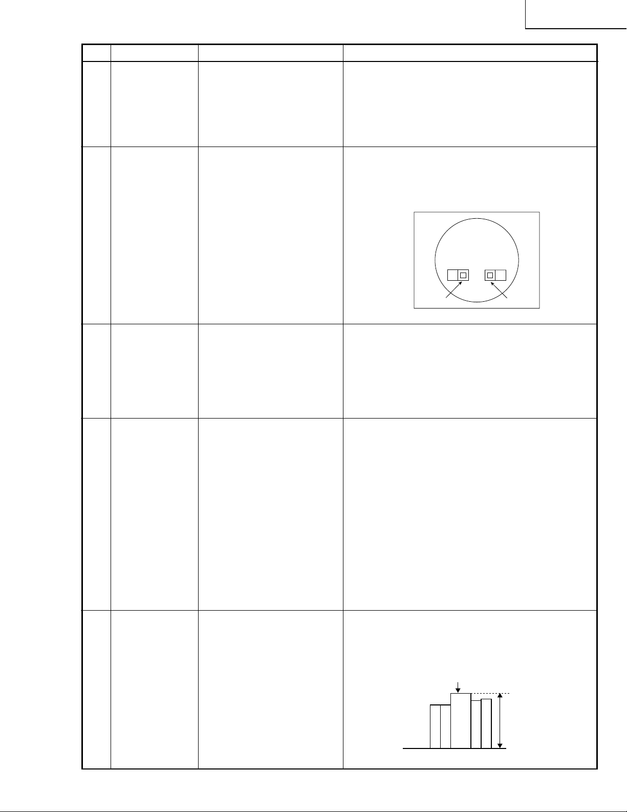
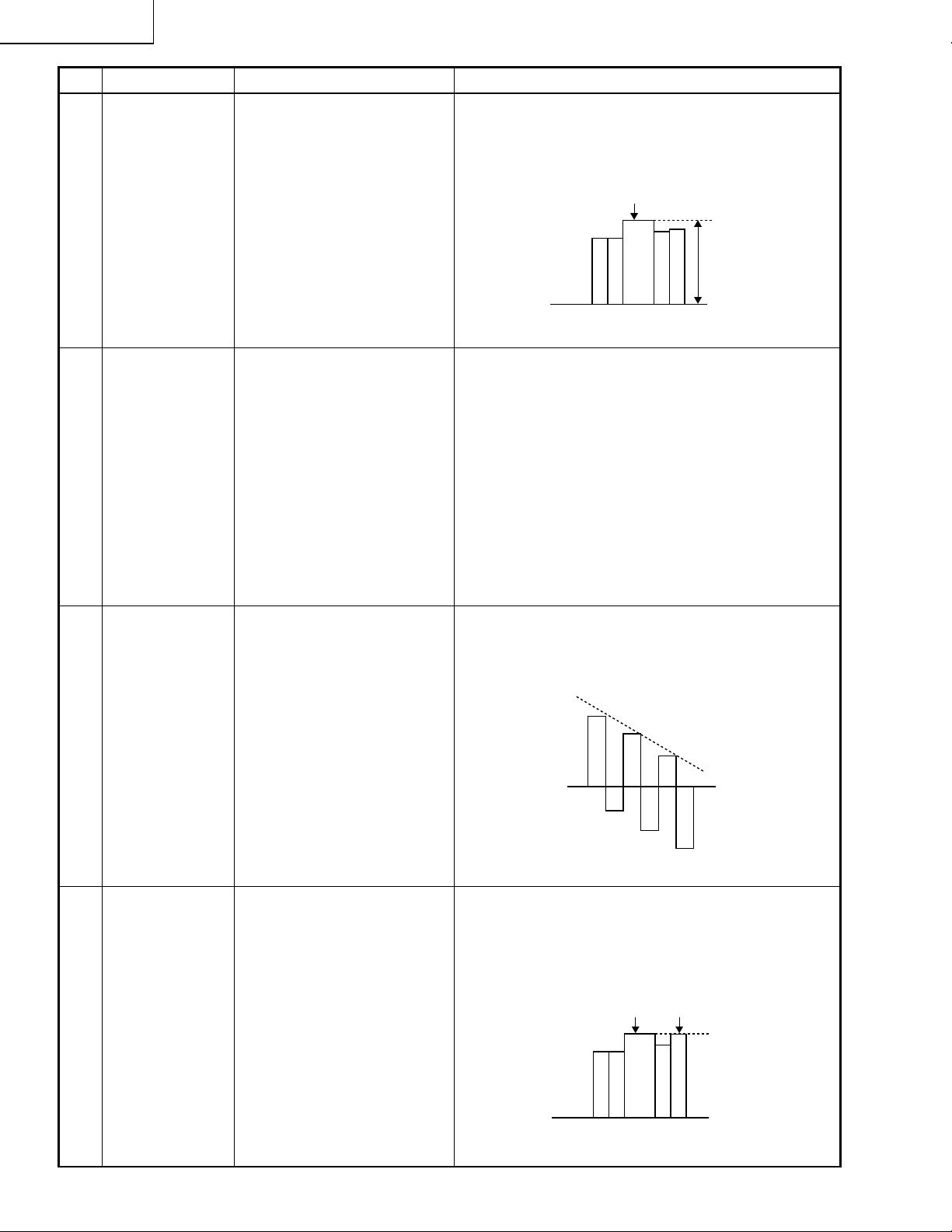
7 RGB gradation
regeneration
adjustment
1. Feed the green-only SMPTE
pattern signal.(XGA)
Group : A/D
Subject : GAIN
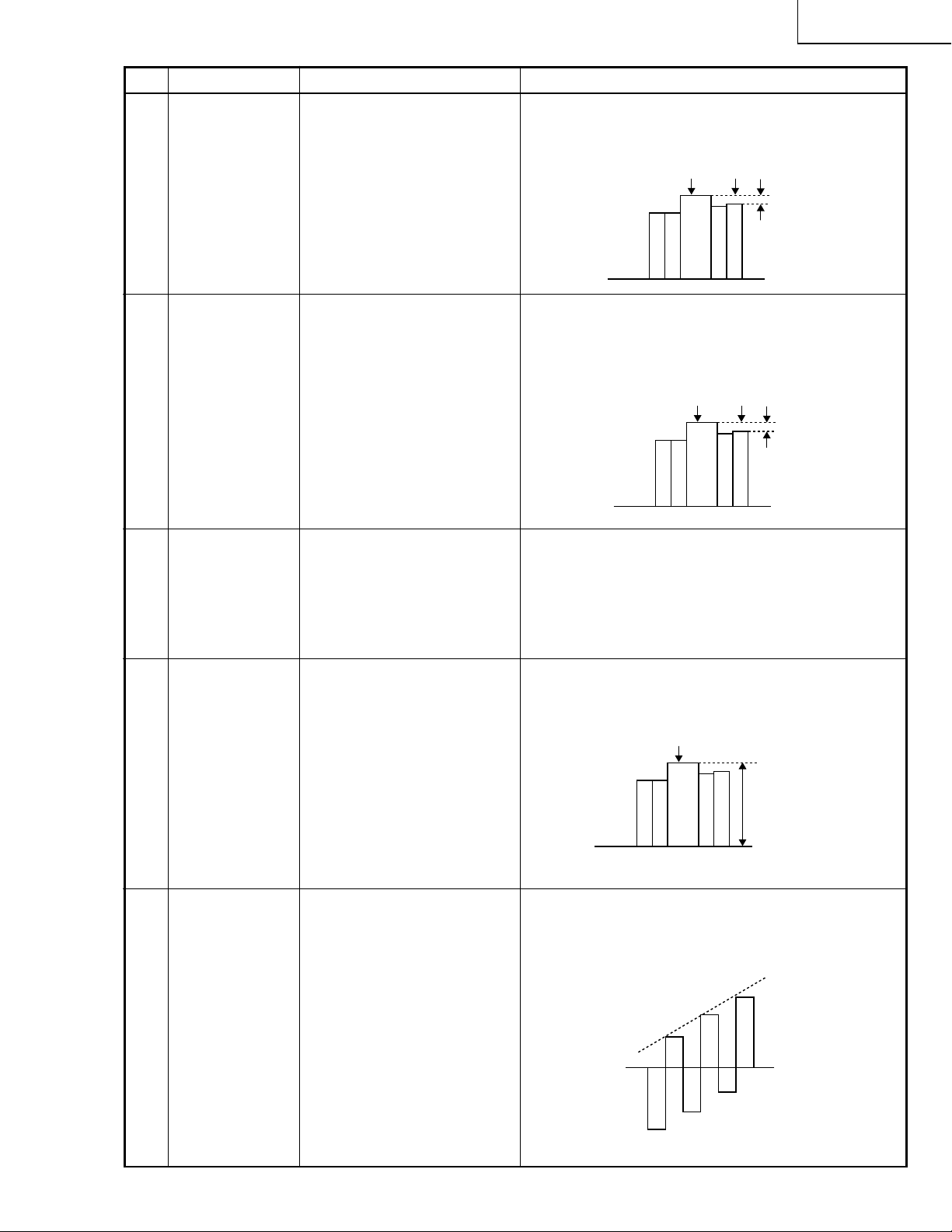
8 RGB white
balance
1. Feed the 32-step gray scale
signal (XGA 60Hz).
Group : A/D
Subject : R-BRIGHT
B-BRIGHT
» With the set's control switch or the remote-control
button, adjust the data until the white-side noise
becomes bitless.
» Adjust the G-GAIN data until the gradation of the
portion 1 (95% and 100% white) shown below
can be slightly recognized. Make sure also that
the gradation of the portion 2 (0% and 5% black)
is visible.
2
1
» Adjust the R-BRIGHT and B-BRIGHT data for the
balance on the gray scale.
(Adjust to the best point.)
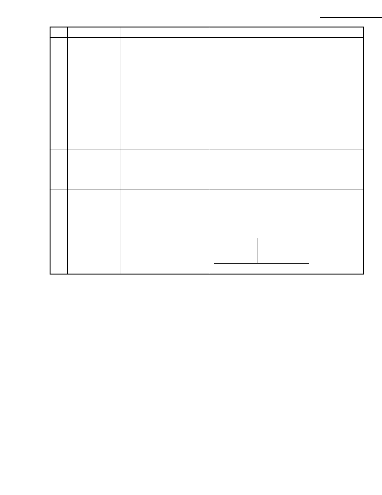
9 Horizontal
center
10 Video picture
adjustment
1. Feed the NTSC monoscope pattern signal.
2. Group : VIDEO 2
Subject : N358-DLY (10)
N443-DLY (0)
PAL-DLY (10)
SECAM-DLY (10)
Make sure the settings are
as above.
3. Group : VIDEO 1
Subject : NTSC-H
1. Feed the split color bar signal.
Group : VIDEO 1
Subject : PICTURE
2. Connect the oscilloscope to
TP805.
» Using the control switches or the remote controller
buttons, adjust the data to have the same
overscan.
» Using the control switches or the remote controller
buttons, adjust the black-to-white (100%) level
difference to 2.1 ±0.02 Vp-p.
100% White
2.1Vp-p
25
Page 26
XG-NV7XU
100% White Red
No. Adjusting point Adjusting conditions Adjusting procedure
11 Video AGC 1. Feed the split color bar sig-
nal.
Group : VIDEO 1
Subject : AGC
2. Connect the oscilloscope to
TP805.
12 Video
brightness
adjustment
1. Feed the baseband (split
color bar) signal.
Group : VIDEO 1
Subject : BRIGHT
2. Press the control switch or
the remote control’s mute
button (to set the gamma
correction to the process
setting).
» Using the control switches or the remote controller
buttons, adjust the black-to-white (100%) level
difference to 1.65 ±0.02 Vp-p.
100% White
1.65Vp-p
» Using the control switches or the remote controller
buttons, adjust the setting until the black signal
becomes bit-less and set to -3 point of value.
13 Tint 1. Feed the split color bar sig-
nal.
Group : VIDEO 1
Subject : TINT
2. Connect the oscilloscope to
TP807.
14 NTSC color
saturation level
1. Feed the split color bar signal.
Group : VIDEO 1
Subject : N-COLOR
2. Connect the oscilloscope to
TP804.
» Using the control switches or the remote controller
buttons, adjust the data to have the -(B-Y) waveform downhill straight.
» Using the control switches or the remote controller
buttons, adjust the difference betw een the 100%
white portion and the red portion to 0.0 ±0.02 Vp-p.
(same as 100% white)
26
Page 27
No. Adjusting point Adjusting conditions Adjusting procedure
XG-NV7XU
15 PAL color
saturation level
16 SECAM color
saturation level
17 Video white
balance
1. Feed the PAL color bar signal.
Group : VIDEO 1
Subject : P-COLOR
2. Connect the oscilloscope to
TP804.
1. Feed the SECAM color bar
signal.
Group : VIDEO 1
Subject : S-COLOR
2. Connect the oscilloscope to
TP804.
1. Feed the NTSC monoscope pattern signal
Group : VIDEO 2
Subject : R OFF-SET
B OFF-SET
» Using the control switches or the remote controller
buttons, adjust the difference between the 100%
white portion and the red portion to 0.28 ±0.02 Vp-p.
100% White Red
» Using the control switches or the remote controller
buttons, adjust the data to have a level difference
of 0.28 ±0.02 Vp-p between the 100% white
portion and the red portion.
100% White Red
» Using the control switches or the remote controller
buttons, adjust so that the entire screen looks
evenly colorless.
18 DVD Contrast 1. Feed the color bar signal of
the 480I component signal to
the D-SUB input terminal.
2. Select the following subject.
Group : DVD
Subject : CONTRAST
3. Connect the oscilloscope to
TP805.
19 D VD Tint 1. Feed the color bar signal of
the 480I component signal
to the D-SUB input terminals. Feed the sync signal
only for the Y signal.
2. Select the following subject.
Group : DVD
Subject : TINT
3. Connect the oscilloscope to
TP807.
» Using the control switch or the button on the
remote controller, adjust the amplitude between
the black and 100% white to 2.1 ±0.02 Vp-p.
100% White
2.1±0.02Vp-p
» Using the control switch or the button on the
remote controller, adjust the B-Y waveform to form
a straight slope.
27
Page 28
XG-NV7XU
No. Adjusting point Adjusting conditions Adjusting procedure
20 DVD Color 1. Feed the color bar signal of
the 480I component signal to
the D-SUB input terminal.
2. Select the following subject.
Group : DVD
Subject : COLOR
3. Connect the oscilloscope to
TP804.
21 Color system
performance
check
22 Video system
performance
check
1. Receive the color bar signal.
1. Receive the monoscope
pattern signal.
» Adjust the level difference between the 100% white
and red portions to 0.1 ±0.02 Vp-p.
100% White Red
» In the process mode and select L1. Chec k the color
and tint.
» In the process mode and select L2. Check the pic-
ture, brightness and sharpness.
23 Audio system
performance
check
24 RGB1
performance
check
25 RGB2
panel link video
check
26 Off-timer
performance
check
» In the process mode nad select L3. Check the bass,
treble and balance.
1. Receive the RGB1 signal. » In the process mode and select L4. Check the pic-
ture, brightness, red, blue, clock, phase, horizontal
position, and vertical position.
1. Make the following settings:
RGB2 mode and XGA specific for panel link. Enter the
32-step gradation pattern.
» Make sure that the gradation pattern is not corrupted
and that the black portion is not too sinking.
» In the process mode and select OFF. Make sure that
the off-timer starts with “5” (minutes), counts down
each minute in 1 second, and turns off the set at “0”.
28
Page 29
No. Adjusting point Adjusting conditions Adjusting procedure
XG-NV7XU
27 Thermistor
performance
check
28 Automatic
synchronization
RGB1
(ANALOG)
29 Auto sync RGB
2 (panel link)
30 IrDA
performance
check
31 Keystone
correction
performance
check
1. Heat the thermistor using a
dryer.
1. Receive the PHASE check
pattern signal.
1. Receive the PHASE check
pattern signal.
» Make sure the “TEMP” is displayed.
» Call the VGA/S-VGA/XGA/SXGA/UXGA mode and
make sure that the clock, phase, horizontal and
vertical positions can be automatically adjusted.
» In the VGA/S-VGA/XGA/SXGA modes, make sure
that the H-POS and V-POS can be automatically
adjusted.
» Make sure the IrDA signal can be received.
» Make sure the keystone correction functions well.
» Make the following settings.32 Factory settings
Process
adjustment
Remote controller
setting
S4 “Factory setting 4”
29
Page 30

XG-NV7XU
ADJUSTING THE PC INTERFACE (CPCi-0036CE01. PC I/F Unit)
1. Initializing the EEPROM
1) Press the S5001 switch to call the process mode.
2) Pick up the item S1 on the SSS menu. (The S1 is used to initialize the PC interface alone. Do not select the
item S2 because otherwise the other data than the PC interface will be initialized.)
2. Adjusting the levels
1 Oscilloscope setting
Set the range to DC 1 V/div. and 5 µ s/div.
2 Input signal
Feed the XGA 1024x768, 60Hz gradation waveform signal and the DTV (720P for example) signal.
3 Level adjustment and checking
1) Press the S5001 switch to call the process mode.
2) Adjust R750 so that the voltage at test point TL119 be 2.6 ±0.05V.
3) Set the BRIGHT data on the A/D menu to 125.
4) Adjust the R-BRIGHT data on the A/D menu so that the voltage at TP3 be 1.7V.
5) Adjust the G-BRIGHT data on the A/D menu so that the voltage at TP2 be 1.7V.
6) Adjust the B-BRIGHT data on the A/D menu so that the voltage at TP1 be 1.7V.
7) Make sure that the GAIN data on the A/D menu is 155.
8) Connect the synchroscope to TP3. Adjust the R-D data on the A/D menu so that the signal’s white peak be
3.6V. (Be also sure that the white and black portions of the gradation are not corrupted.)
9) Connect the synchroscope to TP1. Adjust the B-D data on the A/D menu so that the signal’s white peak be
3.6V. (Be also sure that the white and black portions of the gradation are not corrupted.)
10)
Connect the synchroscope to TP2. Adjust the G-D data on the A/D menu so that the signal’s white peak
be 3.6V. (Be also sure that the white and black portions of the gradation are not corrupted.)
11)
Feed the DTV signal instead. Enter only the Y component, not the Pb and Pr components.
12)
Adjust the R-BRIGHT data on the DTV menu so that the voltage at TP3 be 2.65V.
13)
Adjust the B-BRIGHT data on the DTV menu so that the voltage at TP1 be 2.65V.
14)
Press the S5001 switch to exit the process mode.
30
Page 31

TROUBLE SHOOTING TABLE
Checking the PWB performance
XG-NV7XU
Video input in trouble
Go to "Checking the video unit
circuit".
RGB input in trouble
Feed test pattern signal from
PC.
Is specified cable connected
between PC and projector?
Yes
Is supply voltage as specified?
Yes
Does image appear?
Yes
Go to "Trouble shooting table
for PC I/F unit ".
Remote control in trouble
Go to "Checking the remote
control".
No
Use specified cable.
No
Power circuit in trouble.
No
Check the connectors, starting
from the PC input circuit.
31
Page 32

XG-NV7XU
TROUBLE SHOOTING TABLE (Continued)
Checking the video system
Is the lamp on?
Are specified voltage fed to PA and
PB connectors?
Are there signal inputs at pins (12),
(13) and (17) of SC302?
Are there signal outputs at pins (7) of
IC6006 and (5) of IC6009?
Yes
Go to "Checking IC801
(RGB signal output circuit)".
No
Yes
No
Yes
No
Yes
No
Check IC6008, IC6006,
IC6009 and their peripheral
circuits as well as switching
circuit.
Go to "Lamp fails to light-up".
Check the power circuit and its parts.
Is there signal at pin (4) of IC6001?
Yes
Check the video unit circuit
(IC4501 and IC4001 and its
peripheral circuits).
No
Check the oscillation circuit
of IC6001, and their
peripheral circuits.
32
Page 33

TROUBLE SHOOTING TABLE (Continued)
Checking the Video unit circuit
XG-NV7XU
Is there video signal output at pin (7)
of IC3401?
Yes
Is there video signal input at IC4001?
Yes
Are there signal outputs at pins (6)
and (8) of IC4001?
Yes
Check the low-pass and buffer circuits
of Q4004 thru Q4008. Is the signal as
specified?
Yes
Go to "Checking IC801 (RGB signal
output circuit)".
No
Check the IC3401 selector switch,
terminal voltage and input circuit.
No
Check the low-pass and buffer
circuits of Q4002 thru Q4005.
No
Check IC4001 and its peripheral
circuits (bias).
No
Check Q4004 thru Q4008 and their
peripheral circuits.
33
Page 34

XG-NV7XU
TROUBLE SHOOTING TABLE (Continued)
Checking IC801 (RGB signal output circuit)
No
Are there RGB output waveforms at
pins (31), (32) and (33) of IC801?
Go to "No color or unusual tone",
"No Y signal" or "Out of sync".
Are there output waveforms at pin
(1) of IC6803, IC6804, IC6805?
Are A/D outputs of IC6805, IC6806
and IC6807 as specified?
Go to "Trouble shooting table for PC
I/F unit".
Yes
Yes
Yes
Checking the chroma and Y signals of IC801
No
Check the data transfer and other
performance at pins (17) and (18) of
video IC801.
No
Check IC6802, IC6803, IC6804,
IC6805 and their peripheral circuits.
No
Check the CLK IC6805, IC6806,
IC6807 and their peripheral circuits.
(RGB signal output)
Are there signal inputs at pins (7), (9)
and (25) of SC401?
Yes
Are there output waveforms at pins
(7) of IC6010 (chroma signal) and
(5), (Y signal)of IC6009?
Yes
Are there signal inputs at pins (20)
(chroma signal) and (21) (Y signal)
of IC801?
Yes
Go to "Checking IC801 (RGB signal
output circuit)".
No
Go to "Checking the video unit
circuit".
No
Check the IC6009 and IC6010
switching and their peripheral circuits. If
there is no signal at pins (1) of IC6010
and pin (16) of IC6009 check 3-D noise
reduction circuit (IC8001).
No
Check IC801 and its peripheral
circuits.
Check IC806 (3-D noise reduction
circuit) and its peripheral circuits.
34
Page 35

TROUBLE SHOOTING TABLE (Continued)
Checking IC6008 (3-D noise reduction circuit)
and its peripheral circuits
XG-NV7XU
Are there signal inputs at pins (40)
(Y signal) and (45)(chroma signal) of
IC6008?
Yes
Are there signal outputs at pins (55)
(Y signal) and (51)(chroma signal) of
IC6008?
Yes
Are there signal outputs at the
emitters of Q6013 (Y signal) and
Q6011 (chroma signal)?
Yes
Check IC6009, IC6010 and IC801
(RGB signal output circuit).
No
Check the buffer circuit of Q6001,
Q6003, Q6004, Q6006 and Q6007
as well as Q6009 and Q6010.
No
Check IC6007, IC6010 (memory) and
their peripheral circuits.
No
Check the low-pass circuit around
Q6011, Q6012 and Q6013.
No color or unusual tone (NTSC, PAL)
Is there chroma signal input at pin
(20) of IC801?
Yes
Are there signal outputs at pins
(46)(R-Y) and (45)(B-Y) of IC801?
Yes
No
Go back to the signal processing
block.
No
Check the oscillation of X801 and
X802, and their peripheral circuits.
Check IC805, IC814 and their
peripheral circuits.
35
Page 36

XG-NV7XU
TROUBLE SHOOTING TABLE (Continued)
No or unusual Y signal
Is there Y signal input at pin (21) of
IC801?
Yes
Is there Y signal output at pin (40) of
IC801?
Yes
Is there Y signal output at pin (17) of
IC805?
Yes
Check IC805 and its peripheral
circuits.
No
Go back to the signal processing
block.
No
Check IC801 and its peripheral
circuits.
No
Check IC805 and its peripheral
circuits as well as IC807 (AGC).
No or unusual horizontal sync
Is there horizontal sync pulse output
at pin (56) of IC801?
Yes
Is there horizontal sync pulse output
at pin (9) of IC803?
Yes
No
Check IC801 and its peripheral
circuits.
No
Check the pulse shaping circuit of
IC802 and IC803.
Go to "Trouble shooting table for PC
I/F unit".
No or unusual vertical sync
Is there vertical sync pulse output at
pin (4) of IC801?
Yes
Go to "Trouble shooting table for
PC I/F unit".
No
36
Check IC801 and its peripheral
circuits.
Page 37

TROUBLE SHOOTING TABLE (Continued)
No audio output
XG-NV7XU
Is there audio signal inputs at pin (2)
of IC302?
Is there audio signal outputs at pin (7)
of IC302?
Is there audio signal outputs at pin (6)
of IC301?
If the voltage at pin (7) of IC301 is
not as specified, check Q302, Q303
and their peripheral circuits.
Checkig the Power Unit
No
Yes
No
Yes
No
Yes
Check IC301 and its peripheral
circuits, and the SP connectors and
speakers.
Check the input, the switching circuit
of IC3301 and IC3302, and their
peripheral circuit.
Check the IC5201 control voltage,
and its peripheral circuits.
Check IC301 and its peripheral
circuits.
There are no voltage output at
PA and PB connector.
No
Are PA and PB connector
disconnected or loose?
No
Are AC power switch
(QCNW-5413CEZZ) and
bimetal nomal?
Yes
Replace Power Unit.
Yes
Reconnect the PA and PB
connector.
No
Replace AC Power Switch
(QCNW-5413 CEZZ).
37
Page 38

XG-NV7XU
TROUBLE SHOOTING TABLE (Continued)
Power on
Is the right input selected?
Yes
Are the PC, video and LCP cables as
specified and properly connected?
Yes
With the contrast control at maximum,
does the image appear?
No
Is the voltage at PA and PB
connectors as specified?
Yes
Does the image appear?
Yes
Is the image as specified?
No
Select the right input with remote
control.
No
Use the right cables or reconnect the
cables.
Yes
Readjust the video system.
No
Power circuit faulty.
No
Go to "Checking the clock circuit and
its peripheral circuits".
No
Yes
Is the image's colour as specified?
Yes
A
Does the on-screen display function?
Yes
Does the remote control function?
Yes
End
Check the sync signal circuit and its
peripheral circuits.
No
Check the video circuit and its
peripheral circuits.
No
Go to "Checking the OSD circuit and
its peripheral circuits".
No
Go to "Checking the remote control".
38
Page 39

TROUBLE SHOOTING TABLE (Continued)
Lamp fails to light-up
Turn on the power switch. Is
Yes
discharging sound heard from
the lamp?
XG-NV7XU
Is the lamp out of socket?
Yes
Reconnect the
lamp into socket.
No
Replace the
lamp.
Is power supplied on DMD
formatter?
P8503: pins (1), (3) and (5); 5V
pins (7), (9) and (11); 12V
pins (13), (15), (17)
and (21); 3.3V
Is 2.5V voltage applied between
pins (1) and (3) of DC connector?
Are the cooling fans running?
Is DC 380V voltage applied
between pins (1) and (3) of PL
connector and DC 12V voltage
applied between pins (4) and
(5) of PL connector?
Yes
No
No
No
Yes
Check the power circuit.
NoYes
No No
Yes
Is specified voltage applied at
PA and PB connectors?
Yes
Reconnect the connectors to
their sockets.
Ballast unit in trouble.
DMD output formatter in
trouble.
Is color wheel turning?
Yes
Is there vertical sync signal
input at pin (47) of P8503?
Yes
PC board in trouble.
No
No
Is DB connector or flexible
cable out of position or in poor
contact?
Yes
Reconnect the connector
tightly.
DMD output formatter in
trouble.
39
No
DMD output formatter in
trouble.
Page 40

XG-NV7XU
TROUBLE SHOOTING TABLE FOR PC I/F UNIT-1
Checking the clock circuit and its peripheral circuits
Is X8001 (6MHz) oscillating?
Yes
Is X8002 (32.768kHz) oscillating?
Yes
Is X8003 (1.84MHz) oscillating?
Yes
Is X8004 (22.165MHz) oscillating?
Yes
Is X8005 (14.3185MHz) oscillating?
Yes
Does pin (162) of IC8001 function?
Yes
Checking the panel link input.
Is the signal a panel link input?
Yes
No
No
No
No
No
No
No
X8001 or its peripheral part faulty.
X8002 or its peripheral part faulty.
X8003 or its peripheral part faulty.
X8004 or its peripheral part faulty.
X8005 or its peripheral part faulty.
IC8001 or its peripheral circuit faulty.
B
Are there signals at pins (1) thru (8)
of connector P8003?
Yes
Are there sync signals at pins (47)
and (48) of IC8298?
Yes
B
No
No
Terminal unit defective.
IC8298 defective.
40
Page 41

TROUBLE SHOOTING TABLE FOR PC I/F UNIT-2
Checking the sync signal circuit and its peripheral parts
B
No
Is the sync signal of separate type?
Yes
Are there signals at TP4 and TP5?
Yes
No
Is the sync signal SYNC ON GREEN?
Yes
Is there signal at pin (7) of IC8036?
Yes
Are there signals at pins (149)(TL8034)
and (150)(TL8035) of IC8020?
Yes
No
Is the input a lower-than-XGA-resolution
signal or a video signal?
Yes
Are there signals at pins (26)(TL8043),
(28)(TL8041) and (29)(TL8042) of IC8020?
Yes
Are there signals at even-numbered pins
from (52) thru (100) of IC8503?
Yes
No
No
No
No
No
IC302 or terminal unit defective.
IC23, IC34, IC36 or peripheral part
defective.
IC8025 or peripheral part defective.
IC8020 or peripheral part defective.
IC8029 or peripheral part defective.
XG-NV7XU
C
Checking the PLL circuit and its peripheral parts
C
Are there signals at pins (6) and (22) of
IC8015?
Yes
Are there signals at pins (18) and (19) of
IC8015?
Yes
Checking the video circuit and its
peripheral parts.
Is the higher-than-XGA-resolution display
as specified?
Yes
Is the lower-than-XGA-resolution display
as specified?
Yes
No
No
No
No
IC8025 or peripheral part defective.
IC8015 or peripheral part defective.
Is there a panel link input?
Go to "Checking the SXGA video circuit
and its peripheral parts".
Is there a panel link input?
Go to "Checking the aVGA video circuit
and its peripheral parts".
Yes
D
No
Yes
E
No
Is the display as specified with VCR
connected?
Yes
A
No
Go to "Checking the video circuit and its
peripheral parts".
41
Page 42

XG-NV7XU
TROUBLE SHOOTING TABLE FOR PC I/F UNIT-3
Checking the SXGA
red video circuit
and its peripheral
parts
Is there signal at pin (6) of IC8067?
Yes
Is there signal at the base of Q8009?
Yes
Is there signal at pin (6) of IC8011?
D
Are there signals at pins (21) thru (27)
as well as (33) thru (40) of IC8011?
Are there signals at TL8044 and
TL8046?
Yes
Yes
Yes
No No
Terminal unit, IC301, IC313 or IC312
defective.
No No
IC8067 or peripheral part defective.
No No
Q8009 or peripheral part defective.
No No
IC8011 or peripheral part defective.
No
IC8025 or peripheral part defective.
IC8020 or peripheral part defective.
No
No
Checking the VGA
red video circuit
and its peripheral
parts
Is there signal at pin (6) of IC8067?
Yes
Is there signal at the base of Q8009?
Yes
Is there signal at pin (6) of IC8011?
Yes
Are there signals at pins (21) thru (27)
as well as (33) thru (40) of IC8011?
Yes
Are there signals at pins (112) thru
(119) of IC8020?
Yes
Are there signals at pins (69) thru (73)
as well as (189) thru (192) of IC8020?
Yes
E
F
Are there signals at pins (2) thru (9) of
IC8294?
Yes
Are there signals at pins (86), (88), (90),
(92), (94), (96), (98) and (100) of IC8503?
Yes
Connector P8503 or formatter unit
defective.
No
IC8029 or peripheral part defective.
No
IC8294 or peripheral part defective.
Formatter unit defective.
42
Checking the red
video circuit and
its peripheral parts
No
Are there signals at pins (35) thru (42)
of connector SC8001?
Yes
F
Page 43

TROUBLE SHOOTING TABLE FOR PC I/F UNIT-4
XG-NV7XU
Checking the SXGA
green video circuit
and its peripheral
parts
Is there signal at pin (6) of IC8066?
Yes
Is there signal at the base of Q8007?
Yes
Is there signal at pin (6) of IC8010?
D
Are there signals at pins (21) thru (27)
as well as (33) thru (40) of IC8010?
Are there signals at TL8045 and
TL8047?
Yes
Yes
Yes
No No
Terminal unit, IC301, IC313 or IC312
defective.
No No
IC8066 or peripheral part defective.
No No
Q8007 or peripheral part defective.
No No
IC8010 or peripheral part defective.
No
IC8025 or peripheral part defective.
IC8020 or peripheral part defective.
No
No
Checking the VGA
green video circuit
and its peripheral
parts
Is there signal at pin (6) of IC8066?
Yes
Is there signal at the base of Q8007?
Yes
Is there signal at pin (6) of IC8010?
Yes
Are there signals at pins (21) thru (27)
as well as (33) thru (40) of IC8010?
Yes
Are there signals at pins (165) thru
(177) of IC8020?
Yes
Are there signals at pins (178) thru
(187) of IC8020?
Yes
E
G
Are there signals at pins (2) thru (9) of
IC8295?
Yes
Are there signals at pins (70), (72), (74),
(76), (78), (80), (82) and (84) of IC8503?
Yes
Connector P8503 or formatter unit
defective.
No
IC8029 or peripheral part defective.
No
IC8295 or peripheral part defective.
Formatter unit defective.
43
Checking the green
video circuit and its
peripheral parts
No
Are there signals at pins (25) thru (32)
of connector SC8001?
Yes
G
Page 44

XG-NV7XU
TROUBLE SHOOTING TABLE FOR PC I/F UNIT-5
Checking the SXGA
blue video circuit
and its peripheral
parts
Is there signal at pin (6) of IC8065?
Yes
Is there signal at the base of Q8005?
Yes
Is there signal at pin (6) of IC8009?
D
Are there signals at pins (21) thru (27)
as well as (33) thru (40) of IC8009?
Are there signals at TL8048 and
TL8049?
Yes
Yes
Yes
No No
Terminal unit, IC301, IC313 or IC312
defective.
No No
IC8065 or peripheral part defective.
No No
Q8005 or peripheral part defective.
No No
IC8009 or peripheral part defective.
No
IC8025 or peripheral part defective.
IC8020 or peripheral part defective.
No
No
Checking the VGA
blue video circuit
and its peripheral
parts
Is there signal at pin (6) of IC8065?
Yes
Is there signal at the base of Q8005?
Yes
Is there signal at pin (6) of IC8009?
Yes
Are there signals at pins (21) thru (27)
as well as (33) thru (40) of IC8009?
Yes
Are there signals at pins (85) thru (93)
of IC8020?
Yes
Are there signals at pins (74) thru (83)
of IC8020?
Yes
E
F
Are there signals at pins (2) thru (9) of
IC8296?
Yes
Are there signals at pins (54), (56), (58),
(60), (62), (64), (66) and (68) of IC8503?
Yes
Connector P8503 or formatter unit
defective.
No
IC8029 or peripheral part defective.
No
IC8296 or peripheral part defective.
Formatter unit defective.
44
Checking the blue
video circuit and its
peripheral parts
No
Are there signals at pins (15) thru (22)
of connector SC8001?
Yes
H
Page 45

TROUBLE SHOOTING TABLE FOR PC I/F UNIT-6
Checking the OSD circuit and its peripheral circuits
Display OSD on the screen.
XG-NV7XU
Are there signals at pins (56), (58),
(71) and (72) of IC8048 (TL8054,
TL8053, TL8052 and TL8051)?
Yes
Are there signals at pins (12), (14)
thru (17) and (20) of IC8046?
Yes
Are there signals at pins (23) thru
(42) of IC8046?
Yes
IC8048 or its peripheral circuit faulty.
No
IC8029 or its peripheral circuit faulty.
No
IC8048 or its peripheral circuit faulty.
No
IC8046 or its peripheral circuit faulty.
Checking the remote control
Run the remote control. Are there
signals at pin (47) of P8405 connector
(or R294)?
Yes
No
Output unit faulty.
Using remote controller, is there
signal at pin (8) of IC8001?
Yes
IC8001 faulty.
No
IC8006 circuit faulty.
45
Page 46

CHASSIS LAYOUT
MAIN UNIT
H
G
F
DUNTK9965DE01
XG-NV7XU
BALLAST UNIT
9FU768815400
TERMINAL UNIT
DUNTK9966DE01
PC I/F UNIT
CPCI-0036CE01
E
R/C UNIT
DUNTK9967DE01
D
C
POWER UNIT
9FU768813500
OUTPUT UNIT
9FU768550000
B
S-OUT UNIT
DUNTK9968DE01
A
121110987654321
46
47
Page 47

BLOCK DIAGRAM
H
TERMINAL UNIT
G
F
XG-NV7XU
E
D
C
B
A
121110987654321
48
49
Page 48

O VERALL WIRING DIAGRAM
H
G
F
XG-NV7XU
E
TERMINAL
D
C
B
A
121110987654321
50
51
Page 49

XG-NV7XU
P8503
H
Pin No.
1, 3, 5
7, 9, 11
13, 15, 17, 19
21
G
F
E
D
C
23
25
29
31
33
35
37
39
40
41
42
43
45
47
49
52
54, 56, 58, 60,
62, 64, 66, 68
70, 72, 74, 76,
78, 80, 82, 84
86, 88, 90, 92,
94, 96, 98, 100
DESCRIPTION OF CONNECTOR
I/O
O
O
O
I/O
O
O
O
O
O
O
I
I
O
O
O
O
O
O
O
O
O
O
O
Pin Name
VDD
P12V
P3P3V
SCL
SDA
OLACT
TESTEN
CWINDEX
TFIELD
GYO
LAMPSYNC
LAMPEN
LAMPLIT
PWRGOOD
RESETZ
SYNCVAL
HSYNCZ
VSYNCZ
ACTDATA
CLKIN
BU0-7
GY1-8
RV0-7
Signal Name
Serial BUs CLock
Serial BUs Date
Overlay Active
Test Enable
Color Wheel Index
Lamp Sync
Lamp Enable
Lamp Lit Indication
System Power Good
System Reset Sign
Sync V alid
H-sync
V-sync
Active Data
Clock in
+5V
+12V
+3.3V
I2C bus clock
I2C bus data
Not used (pull-down)
Not used (pull-down)
Color wheel turn detection signal
Not used (pull-down)
Not used (pull-down)
Lamp AC drive control pulse signal
Not used (open)
Not used (pull-up)
DMD output power control signal, High = ON
Lamp on control signal
Not used (pull-up)
Horizontal sync
Vertical sync
Screen active signal
Dot clock (57.27MHz)
Blue data signal
Green data signal
Red data signal
Description
P8011 “DC”
Pin No.
1
3
B
I/O
O
I
Pin Name
SCI
LAMPFLUG
Signal Name
Start Control Input
Lamp Flug
Lamp AC drive control pulse signal
Low = Lamp on, High = Lamp off
P8021 “DB”
Pin No.
4
Note: The I/O (input or output) is a signal flow that is seen from the PC interface unit.
A
I/O
I
Pin Name
CWINDEX
Signal Name
Color Wheel Index
Color wheel turn detection signal
52
Description
Description
87109654321
Page 50

DESCRIPTION OF SCHEMATIC DIAGRAM
XG-NV7XU
VOLTAGE MEASUREMENT CONDITION:
1. Voltages at test points are measured at the
supply voltage of AC 120V. Signals are fed by a
color bar signal generator for servicing purpose and
the above voltages are measured with a 20k ohm/V
tester.
WAVEFORM MEASUREMENT CONDITION:
1. Wav eforms at test points are observed at the supply
voltage of AC 120V. Signals are fed by a color bar
signal generator for servicing purpose.
INDICATION OF RESISTOR & CAPACITOR:
RESISTOR
1. The unit of resistance “Ω” is omitted.
(K=kΩ=1000 Ω, M=MΩ).
2. All resistors are ± 5%, unless otherwise noted.
(J= ± 5%, F= ± 1%, D= ± 0.5%)
3. All resistors are 1/10W, unless otherwise noted.
4. All resistors are Carbon type, unless otherwise
noted.
C : Solid
S : Oxide Film T : Special
N : Metal Coating
W
: Cement
CAPACITOR
1. All capacitors are µF, unless otherwise noted.
(P=pF=µµF).
2. All capacitors are 50V, unless otherwise noted.
3. All capacitors are Ceramic type, unless otherwise
noted.
(ML): Mylar (TA): Tantalum
(PF): Polypro Film (ST): Styrol
CAUTION:
This circuit diagram is original one, therefore there may be a
slight difference from yours.
SAFETY NOTES:
1. DISCONNECT THE AC PLUG FROM THE AC
OUTLET BEFORE REPLACEING PARTS.
2. SEMICONDUCTOR HEAT SINKS SHOULD BE
REGARDED AS POTENTIAL SHOCK HAZARDS
WHEN THE CHASSIS IS OPERATING.
IMPORTANT SAFETY NOTICE:
PARTS MARKED WITH “å” ( ) ARE
IMPORTANT FOR MAINTAINING THE SAFETY OF
THE SET. BE SURE TO REPLACE THESE PARTS
WITH SPECIFIED ONES FOR MAINTAINING THE
SAFETY AND PERFORMANCE OF THE SET.
1 TP804
(R)
H : 10µsec/div
V : 0.5V/div
5 Q6008 Emitter
(4FSC)
H : 50µsec/div
V : 0.5V/div
WAVEFORMS
2 TP805
(G)
H : 20µsec/div
V : 0.5V/div
6 Q4008 Emitter
(Y-signal)
H : 10µsec/div
V : 0.2V/div
3 TP807
(B-Y)
H : 20µsec/div
V : 1V/div
7 Q4006 Emitter
(CHROMA signal)
H : 10µsec/div
V : 0.2V/div
4 IC801 56-pin
(H-OUT)
H : 20µsec/div
V : 1V/div
1716 1918151413121110
53
Page 51

XG-NV7XU
Ë
MAIN UNIT-1/7
H
G
F
E
D
C
B
A
121110987654321
54
55
Page 52

XG-NV7XU
Ë
MAIN UNIT-2/7
H
G
F
E
D
C
B
A
121110987654321
56
57
Page 53

XG-NV7XU
Ë
MAIN UNIT-3/7
H
G
F
E
D
C
B
A
121110987654321
58
59
Page 54

XG-NV7XU
Ë
MAIN UNIT-4/7
H
G
F
E
D
C
B
A
121110987654321
60
61
Page 55

XG-NV7XU
Ë
MAIN UNIT-5/7
H
G
F
E
D
C
B
A
121110987654321
62
63
Page 56

XG-NV7XU
Ë
MAIN UNIT-6/7
H
G
F
E
D
C
B
A
121110987654321
64
65
Page 57

XG-NV7XU
Ë
MAIN UNIT-7/7
H
G
F
E
D
C
B
A
121110987654321
66
67
Page 58

XG-NV7XU
Ë
TERMINAL UNIT
H
G
F
E
D
C
B
A
121110987654321
68
69
Page 59

XG-NV7XU
Ë
SOUND OUT UNIT
H
G
F
E
D
C
B
A
121110987654321
70
71
Page 60

XG-NV7XU
Ë
R/C RECEIVER UNIT
H
H
G
G
F
F
E
E
D
D
C
C
B
B
A
A
87109654321
654321
72
Page 61

XG-NV7XU
Ë
OPERATION KEY UNIT
H
G
F
E
D
C
B
A
1716 1918151413121110
654321
73
Page 62

XG-NV7XU
Ë
PC I/F UNIT-1/12
H
G
F
E
D
C
B
A
121110987654321
74
75
Page 63

XG-NV7XU
Ë
PC I/F UNIT-2/12
H
G
F
E
D
C
B
A
121110987654321
76
77
Page 64

XG-NV7XU
Ë
PC I/F UNIT-3/12
H
G
F
E
D
C
B
A
121110987654321
78
79
Page 65

XG-NV7XU
Ë
PC I/F UNIT-4/12
H
G
F
E
D
C
B
A
121110987654321
80
81
Page 66

XG-NV7XU
Ë
PC I/F UNIT-5/12
H
G
F
E
D
C
B
A
121110987654321
82
83
Page 67

XG-NV7XU
Ë
PC I/F UNIT-6/12
H
G
F
E
D
C
B
A
121110987654321
84
85
Page 68

XG-NV7XU
Ë
PC I/F UNIT-7/12
H
G
F
E
D
C
B
A
121110987654321
86
87
Page 69

XG-NV7XU
Ë
PC I/F UNIT-8/12
H
G
F
E
D
C
B
A
121110987654321
88
89
Page 70

XG-NV7XU
Ë
PC I/F UNIT-9/12
H
G
F
E
D
C
B
A
121110987654321
90
91
Page 71

XG-NV7XU
Ë
PC I/F UNIT-10/12
H
G
F
E
D
C
B
A
121110987654321
92
93
Page 72

XG-NV7XU
Ë
PC I/F UNIT-11/12
H
G
F
E
D
C
B
A
121110987654321
94
95
Page 73

XG-NV7XU
Ë
PC I/F UNIT-12/12
H
G
F
E
D
C
B
A
121110987654321
96
97
Page 74

XG-NV7XU
Ë
PC I/F (SUB UNIT-1)
H
H
G
G
F
F
E
E
D
D
C
C
B
B
A
A
87109654321
654321
98
Page 75

XG-NV7XU
Ë
PC I/F (SUB UNIT-2)
H
G
F
E
D
C
B
A
1716 1918151413121110
654321
99
Page 76

XG-NV7XU
PRINTED WIRING BOARD ASSEMBLIES
H
G
F
E
D
C
B
A
Main Unit (Wiring Side)
654321
100
Page 77

XG-NV7XU
H
G
F
E
D
C
B
A
Main Unit (Component Side)
654321
101
Page 78

XG-NV7XU
H
PC I/F (Sub Unit-1)
(Wiring Side)
G
F
E
PC I/F (Sub Unit-2)
(Wiring Side)
D
C
B
A
PC I/F Unit (Wiring Side)
102
654321
Page 79

XG-NV7XU
H
G
F
E
D
C
B
A
PC I/F Unit (Component Side)
654321
103
Page 80

XG-NV7XU
H
G
F
E
Sound Out Unit (Wiring Side)
R/C Receiver Unit (Wiring Side)
D
C
B
Terminal Unit (Wiring Side)
A
654321
104
Page 81

XG-NV7XU
H
G
F
E
Sound Out Unit (Component Side)
R/C Receiver Unit (Component Side)
D
C
B
Terminal Unit (Component Side)
A
654321
105
Page 82

XG-NV7XU
H
G
F
E
Operation Key Unit (Wiring Side)
D
C
B
A
Operation Key Unit (Component Side)
654321
106
Page 83

XG-NV7XU
Ref. No. Part No. ★ Description Code Ref. No. Part No. ★ Description Code
PARTS LIST
PARTS REPLACEMENT
Parts marked with "å" are important for maintaining the safety of
the set. Be sure to replace these parts with specified ones for maintaining the safety and performance of the set.
Les pieces marquées "å" sont importantes pour maintenir la sécurité
de l'appareil. Ne remplacer ces pieces que par des pieces dont le
numéro est spécifié pour maintenir la sécurité et protéger le bon
fonctinnement de l'appareil.
"HOW TO ORDER REPLACEMENT PARTS"
To have your order filled promptly and correctly, please furnish the
following informations.
1. MODEL NUMBER 2. REF. NO.
3. PART NO. 4. DESCRIPTION
5. CODE 6. QUANTITY
in USA: Contact your nearest SHARP Parts Distributor.
For location of SHARP Parts Distributor,
Please call Toll-Free; 1-800-BE-SHARP
in CANADA: Contact SHARP Electronics of Canada Limited
Phone (416) 890-2100.
★ MARK: SPARE PARTS-DELIVERY SECTION
Ref. No. Part No. ★ Description Code
DMD ASSEMBLY
NOTE: THE PARTS HERE SHOWN ARE SUPPLIED AS AN
ASSEMBLY BUT NOT INDEPENDENTLY.
CCHSK0076CE01 J DMD Chassis Ass’y HF
(The optics, lamp, power and ballast units as well
as the bottom cabinet can be taken out, referring to
the Exploded View, and be employed for other
units.)
9FU768550000 J DMD/Driver Ass'y
(Note: The carrying case (9FU768815710),
optionally available, is needed for transporting the
DMD/Driver assembly.)
PRINTED WIRING BOARD ASSEMBLIES
(NOT REPLACEMENT ITEM)
DUNTK9965DE01 – Main Unit —
DUNTK9966DE01 – Terminal Unit —
DUNTK9967DE01 – R/C Receiver Unit —
DUNTK9968DE01 – Sound Out Unit —
CPCi-0036CE01 – PC I/F Unit —
DUNTK9965DE01
MAIN UNIT
INTEGRATED CIRCUITS
IC302 VHiTA8184F/-1 J TA8184F AN
IC801 VHiTDA8854H-2 J TDA8854H/N2 BD
IC802 VHiTHC4538T-1 J TC74HC4538AFT AL
IC803 VHiTHC4538T-1 J TC74HC4538AFT AL
IC805 VHiTDA4565/-1 J TDA4565/V6 AN
IC807 VHiNJM2060V-1 J NJM2060V AF
IC812 VHiT7SET08U-1 J TC7SET08FU AE
IC814 VHiTA8814N/-1 J TA8814N AV
IC4001 VHiMC141627-1 J MC141627FT AY
IC4301 VHiTHC4538T-1 J TC74HC4538AFT AL
IC4302 VHiCXA1839Q-1 J CXA1839 AZ
IC4303 VHiPQ20VZ11-1 J PQ20VZ11 AH
IC4501 VHiPD64081B-1 J UPD64081BGF3BA BD
IC4502 VHiMC14577F-1 J MC14577BF AG
IC4503 RH-iX3084CEZZ J HY514264BJC-50 AS
IC4505 VHiPST600iM-1 J IC-PST600IMT AE
IC4506 VHiT7SET08U-1 J TC7SET08FU AE
IC4507 VHiM40C568H-1 J MB40C568HPFV-G AQ
IC4508 VHiTC4S66F/-1 J TC4S66F AD
IC4509 VHiNJM2233V-1 J NJM2233V AE
IC4511 VHiTC4W66U/-1 J TC4W66FU AF
IC4512 RH-iX2963CEZZ J X24645S8T2 AX
IC4514 VHiPQ20VZ11-1 J PQ20VZ11 AH
IC5201 VHiM62352GP-1 J M62352GP AQ
IC5340 VHiM62320FP-1 J M62320FP AK
IC6001 VHiNJM2240M-1 J NJM2240M AG
IC6003 VHiBA7046F/-1 J BA7046F AF
IC6005 VHiNJM2283V-1 J NJM2283V AG
IC6006 VHiNJM2234M-1 J NJM2234M AF
IC6007 VHiPST600DM-1 J IC-PST600DMT AE
IC6008 VHiTC90A11F-1 J TC90A11F AZ
IC6009 VHiNJM2283V-1 J NJM2283V AG
IC6010 VHiM518221S-1 J MSM518221-30JS BA
IC6801 VHiNJM431E/-1 J NJM431E-TE1 AF
IC6802 VHiNJM2902V-1 J NJM2902V AD
IC6803 VHiAD8051AT-1 J AD8051ART AP
IC6804 VHiAD8051AT-1 J AD8051ART AP
IC6805 VHiAD8051AT-1 J AD8051ART AP
IC6806 VHiM40C568H-1 J MB40C568HPFV-G AQ
IC6807 VHiM40C568H-1 J MB40C568HPFV-G AQ
IC6808 VHiM40C568H-1 J MB40C568HPFV-G AQ
IC7205 RH-iX2296CEZZ J TC7S66F AD
TRANSISTORS
Q801 VS2PD601AR/-1 J 2PD601AR AB
Q802 VS2PB709AR/-1 J 2PB709AR AB
Q803 VS2PD601AR/-1 J 2PD601AR AB
Q804 VS2PB709AR/-1 J 2PB709AR AB
Q805 VSDTC144EU/-1 J DTC144EU AB
Q806 VS2PD601AR/-1 J 2PD601AR AB
Q807 VS2PD601AR/-1 J 2PD601AR AB
Q808 VS2PD601AR/-1 J 2PD601AR AB
Q809 VS2PB709AR/-1 J 2PB709AR AB
Q810 VS2PB709AR/-1 J 2PB709AR AB
Q811 VSDTC144EU/-1 J DTC144EU AB
Q812 VS2PD601AR/-1 J 2PD601AR AB
Q813 VS2PD601AR/-1 J 2PD601AR AB
Q4002 VS2PD601AR/-1 J 2PD601AR AB
Q4003 VS2PD601AR/-1 J 2PD601AR AB
Q4004 VS2PB709AR/-1 J 2PB709AR AB
Q4005 VSiMX2/////-1 J iMX2 AB
Q4006 VS2PD601AR/-1 J 2PD601AR AB
Q4007 VS2PD601AR/-1 J 2PD601AR AB
Q4008 VS2PD601AR/-1 J 2PD601AR AB
Q4301 VS2PD601AR/-1 J 2PD601AR AB
Q4302 VS2PD601AR/-1 J 2PD601AR AB
Q4303 VS2PD601AR/-1 J 2PD601AR AB
Q4304 VS2PD601AR/-1 J 2PD601AR AB
Q4305 VS2PD601AR/-1 J 2PD601AR AB
Q4306 VS2PD601AR/-1 J 2PD601AR AB
107
Page 84

XG-NV7XU
Ref. No. Part No. ★ Description Code Ref. No. Part No. ★ Description Code
DUNTK9965DE01
MAIN UNIT (Continued)
Q4307 VS2PD601AR/-1 J 2PD601AR AB
Q4308 VS2PD601AR/-1 J 2PD601AR AB
Q4309 VSDTC144EU/-1 J DTC144EU AB
Q4310 VSBSN20////-1 J BSN20 AD
Q4311 VSBSN20////-1 J BSN20 AD
Q4501 VS2PB709AR/-1 J 2PB709AR AB
Q4502 VS2PB709AR/-1 J 2PB709AR AB
Q4503 VS2PB709AR/-1 J 2PB709AR AB
Q4504 VS2PB709AR/-1 J 2PB709AR AB
Q4505 VS2SC2412KQ-1 J 2SC2412KQ AA
Q4506 VS2PD601AR/-1 J 2PD601AR AB
Q4507 VS2PB709AR/-1 J 2PB709AR AB
Q4508 VS2PD601AR/-1 J 2PD601AR AB
Q4509 VS2PB709AR/-1 J 2PB709AR AB
Q4510 VS2PB709AR/-1 J 2PB709AR AB
Q4511 VS2PD601AR/-1 J 2PD601AR AB
Q4512 VS2PB709AR/-1 J 2PB709AR AB
Q6001 VS2PD601AR/-1 J 2PD601AR AB
Q6002 VS2PD601AR/-1 J 2PD601AR AB
Q6003 VS2PB709AR/-1 J 2PB709AR AB
Q6004 VS2PD601AR/-1 J 2PD601AR AB
Q6005 VS2PD601AR/-1 J 2PD601AR AB
Q6006 VS2PD601AR/-1 J 2PD601AR AB
Q6007 VS2PB709AR/-1 J 2PB709AR AB
Q6008 VS2PD601AR/-1 J 2PD601AR AB
Q6009 VS2PD601AR/-1 J 2PD601AR AB
Q6010 VS2PD601AR/-1 J 2PD601AR AB
Q6011 VS2PD601AR/-1 J 2PD601AR AB
Q6012 VS2PD601AR/-1 J 2PD601AR AB
Q6013 VS2PD601AR/-1 J 2PD601AR AB
Q6014 VS2PD601AR/-1 J 2PD601AR AB
Q6801 VS2PD601AR/-1 J 2PD601AR AB
Q6802 VS2PB709AR/-1 J 2PB709AR AB
Q6803 VS2PD601AR/-1 J 2PD601AR AB
Q6804 VS2PD601AR/-1 J 2PD601AR AB
Q6805 VS2PD601AR/-1 J 2PD601AR AB
Q7201 VS2PD601AR/-1 J 2PD601AR AB
DIODES
D801 VHDDAN202K/-1 J Diode AB
D804 VHDMA152WA/-1 J Diode AA
D4001 VHDMA153///-1 J Diode AB
D4002 VHD1SS355//-1 J Diode AB
D4302 VHDDAN202K/-1 J Diode AB
D4501 VHDDAN202K/-1 J Diode AB
D5001 VHDHRW0702A-1 J Diode AE
D5002 VHDHRW0702A-1 J Diode AE
D5003 VHDHRW0702A-1 J Diode AE
D5004 VHDHRW0702A-1 J Diode AE
D5005 VHDMA137///-1 J Diode AC
D5006 VHDMA137///-1 J Diode AC
D5007 VHDMA137///-1 J Diode AC
D5008 VHDMA137///-1 J Diode AC
D5009 VHDHRW0702A-1 J Diode AE
D5010 VHDHRW0702A-1 J Diode AE
D5011 VHDHRW0702A-1 J Diode AE
D5012 VHDHRW0702A-1 J Diode AE
D5013 VHDHRW0702A-1 J Diode AE
D5014 VHDMA137///-1 J Diode AC
D5015 VHDMA137///-1 J Diode AC
D5016 VHDMA137///-1 J Diode AC
D5017 VHDMA137///-1 J Diode AC
D5018 VHDMA137///-1 J Diode AC
D6001 RH-EX0879CEZZ J Zener Diode AD
D6002 RH-EX0879CEZZ J Zener Diode AD
PACKAGED CIRCUITS
X801 RCRSB0253CEZZ J Crystal AL
X802 RCRSB0254CEZZ J Crystal AL
X4501 RCRSB0258CEZZ J Crystal AG
FL4001 RCiLF0316CEZZ J Filter AG
COILS AND FILTERS
FL4002 RCiLF0316CEZZ J Filter AG
FL4501 RCiLF0306CEZZ J Filter AH
FL4502 RCiLV0108GEZZ J Band-Pass Coil AG
L801 VP-1M330J4R2N J Peaking 33µH AC
L4001 VP-1M330J4R2N J Peaking 33µH AC
L4002 VP-1M330J4R2N J Peaking 33µH AC
L4003 VP-1M270J3R8N J Peaking 27µH AC
L4501 VP-1M4R7J1R2N J Peaking 4.7µH AB
L4502 VP-1M220J2R9N J Peaking 22µH AC
L4510 VP-1M220J2R9N J Peaking 22µH AC
L6001 VP-1M270J3R8N J Peaking 27µH AC
L6002 VP-1M220J2R9N J Peaking 22µH AC
L6003 VP-1M330J4R2N J Peaking 33µH AC
CAPACITORS
[MLFT··· Multi Layer Film Tip]
C314 VCKYCY1CF104Z J 0.1 16V Ceramic AA
C315 VCE9PF1CW106M J 10 16V Elect.(N.P) AC
C316 VCKYCY1CF104Z J 0.1 16V Ceramic AA
C317 VCFRED1HM822J J 8200p 50V MLFT AD
C318 VCKYCY1CF104Z J 0.1 16V Ceramic AA
C319 VCFYEC1CM334J J 0.33 16V MLFT AE
C320 VCKYCY1CF104Z J 0.1 16V Ceramic AA
C321 VCEAPV1CW106M J 10 16V Electrolytic AD
C322 VCKYCY1CF104Z J 0.1 16V Ceramic AA
C323 VCKYCY1EF104Z J 0.1 25V Ceramic AA
C324 VCEAPV1CW106M J 10 16V Electrolytic AD
C325 VCKYCY1EF104Z J 0.1 25V Ceramic AA
C326 VCKYCY1CF154Z J 0.15 16V Ceramic AB
C327 VCEAPF1CW107M J 100 16V Electrolytic AD
C328 VCKYCY1HB102K J 1000p 50V Ceramic AA
C329 VCEAPF1CW107M J 100 16V Electrolytic AD
C801 VCKYCY1EF104Z J 0.1 25V Ceramic AA
C802 VCKYCY1EF104Z J 0.1 25V Ceramic AA
C803 VCEAPV1HW225M J 2.2 50V Electrolytic AC
C804 VCFYEC1CM223J J 0.022 16V Mylar AC
C805 VCKYCY1HB103K J 0.01 50V Ceramic AA
C806 VCFYEC1CM274J J 0.27 16V Mylar AE
C807 VCKYCY1EF104Z J 0.1 25V Ceramic AA
C808 VCEAPF1CW107M J 100 16V Electrolytic AD
C809 VCKYCY1EF104Z J 0.1 25V Ceramic AA
C810 VCFYEC1CM274J J 0.27 16V Mylar AE
C811 VCKYCY1CF224Z J 0.22 16V Ceramic AA
C812 VCEAPV1CW106M J 10 16V Electrolytic AD
C813 VCKYCY1EF104Z J 0.1 25V Ceramic AA
C814 VCKYCY1EF104Z J 0.1 25V Ceramic AA
C815 VCKYCY1EF104Z J 0.1 25V Ceramic AA
C816 VCE9PF1CW106M J 10 16V Elect.(N.P) AC
C817 VCKYCY1EF104Z J 0.1 25V Ceramic AA
C818 VCKYCY1EF104Z J 0.1 25V Ceramic AA
C819 VCKYCY1EF104Z J 0.1 25V Ceramic AA
C820 VCKYCY1EF104Z J 0.1 25V Ceramic AA
C821 VCKYCY1EF104Z J 0.1 25V Ceramic AA
C823 VCCCCY1HH180J J 18p 50V Ceramic AA
C824 VCCCCY1HH180J J 18p 50V Ceramic AA
C825 VCFRED1HM332J J 3300p 50V Mylar AD
C826 VCKYCY1EF104Z J 0.1 25V Ceramic AA
C827 VCEAPF1CW107M J 100 16V Electrolytic AD
C828 VCKYCY1EF104Z J 0.1 25V Ceramic AA
C829 VCKYCY1EF104Z J 0.1 25V Ceramic AA
C830 VCFRED1HM222J J 2200p 50V Mylar AC
C831 VCEAPV1HW105M J 1.0 50V Electrolytic AC
C832 VCFRED1HM472J J 4700p 50V Mylar AD
C834 VCE9PF1CW106M J 10 16V Elect.(N.P) AC
C835 VCEAPV1CW106M J 10 16V Electrolytic AD
C836 VCEAPV1CW106M J 10 16V Electrolytic AD
C841 VCKYCY1EF104Z J 0.1 25V Ceramic AA
C842 VCKYCY1EF104Z J 0.1 25V Ceramic AA
C843 VCCCCY1EH102J J 1000p 25V Ceramic AB
C844 VCCCCY1EH102J J 1000p 25V Ceramic AB
C845 VCKYCY1EF104Z J 0.1 25V Ceramic AA
C846 VCCCCY1EH102J J 1000p 25V Ceramic AB
108
Page 85

XG-NV7XU
Ref. No. Part No. ★ Description Code Ref. No. Part No. ★ Description Code
DUNTK9965DE01
MAIN UNIT (Continued)
C847 VCCCCY1EH102J J 1000p 25V Ceramic AB
C848 VCKYCY1EF104Z J 0.1 25V Ceramic AA
C858 VCE9PF1HW105M J 1.0 50V Elect.(N.P) AC
C859 VCE9PF1HW105M J 1.0 50V Elect.(N.P) AC
C860 VCCCCY1HH470J J 47p 50V Ceramic AA
C861 VCCCCY1HH820J J 82p 50V Ceramic AA
C862 RC-EZ1146CEZZ J 27 16V Electrolytic AG
C863 VCKYCY1EF104Z J 0.1 25V Ceramic AA
C864 VCCCCY1HH221J J 220p 50V Ceramic AA
C865 VCCCCY1HH221J J 220p 50V Ceramic AA
C866 VCCCCY1HH221J J 220p 50V Ceramic AA
C867 VCCCCY1HH470J J 47p 50V Ceramic AA
C868 VCCCCY1HH470J J 47p 50V Ceramic AA
C870 VCEAPV1CW476M J 47 16V Electrolytic AD
C875 VCKYCY1EF104Z J 0.1 25V Ceramic AA
C877 VCKYCY1EF104Z J 0.1 25V Ceramic AA
C878 VCEAPV1HW225M J 2.2 50V Electrolytic AC
C879 VCE9PF1HW105M J 1.0 50V Elect.(N.P) AC
C880 VCCCCY1HH101J J 100p 50V Ceramic AA
C891 VCKYCY1EF104Z J 0.1 25V Ceramic AA
C892 VCKYCY1EF104Z J 0.1 25V Ceramic AA
C918 VCEAPV1CW476M J 47 16V Electrolytic AD
C922 VCKYCY1HB103K J 0.01 50V Ceramic AA
C937 VCKYCY1EF104Z J 0.1 25V Ceramic AA
C938 VCCCCY1HH390J J 39p 50V Ceramic AA
C939 VCKYCY1EF104Z J 0.1 25V Ceramic AA
C940 VCKYCY1EF104Z J 0.1 25V Ceramic AA
C950 VCKYCY1HB103K J 0.01 50V Ceramic AA
C951 VCKYCY1HB103K J 0.01 50V Ceramic AA
C962 VCKYCY1EF104Z J 0.1 25V Ceramic AA
C963 VCEAPV1CW226M J 22 16V Electrolytic AD
C964 VCFYEC1CM104J J 0.1 16V Mylar AD
C965 VCKYCY1EF104Z J 0.1 25V Ceramic AA
C966 VCKYCY1EF104Z J 0.1 25V Ceramic AA
C968 VCKYCY1HB103K J 0.01 50V Ceramic AA
C976 VCKYCY1HB103K J 0.01 50V Ceramic AA
C3510 VCCCCY1HH820J J 82p 50V Ceramic AA
C3512 VCEAPV0JW476M J 47 6.3V Electrolytic AD
C3513 VCKYTV1CF225Z J 2.2 16V Ceramic AC
C3514 VCKYTV1CF225Z J 2.2 16V Ceramic AC
C4001 VCEAPV0JW226M J 22 6.3V Electrolytic AC
C4002 VCEAPV0JW226M J 22 6.3V Electrolytic AC
C4003 VCKYCY1CF104Z J 0.1 16V Ceramic AA
C4004 VCEAPV1CW106M J 10 16V Electrolytic AD
C4005 VCKYCY1CF104Z J 0.1 16V Ceramic AA
C4006 VCKYCY1EF104Z J 0.1 25V Ceramic AA
C4007 VCKYCY1CF104Z J 0.1 16V Ceramic AA
C4008 VCKYCY1EF104Z J 0.1 25V Ceramic AA
C4009 VCEAPV0JW476M J 47 6.3V Electrolytic AD
C4010 VCEAPV1HW105M J 1.0 50V Electrolytic AC
C4011 VCEAPV1CW106M J 10 16V Electrolytic AD
C4012 VCKYCY1CF104Z J 0.1 16V Ceramic AA
C4013 VCEAPV1CW106M J 10 16V Electrolytic AD
C4014 VCKYCY1CF104Z J 0.1 16V Ceramic AA
C4015 VCEAPV1HW105M J 1.0 50V Electrolytic AC
C4016 VCKYCY1HB103K J 0.01 50V Ceramic AA
C4017 VCE9PF1HW105M J 1.0 50V Elect.(N.P) AC
C4018 VCCCCY1HH270J J 27p 50V Ceramic AA
C4019 VCCCCY1HH270J J 27p 50V Ceramic AA
C4020 VCKYCY1HB103K J 0.01 50V Ceramic AA
C4021 VCKYCY1CF104Z J 0.1 16V Ceramic AA
C4022 VCKYCY1HB103K J 0.01 50V Ceramic AA
C4023 VCEAPV1CW226M J 22 16V Electrolytic AD
C4024 VCKYCY1CF104Z J 0.1 16V Ceramic AA
C4301 VCEAPV1CW106M J 10 16V Electrolytic AD
C4302 VCKYCY1CF104Z J 0.1 16V Ceramic AA
C4303 VCCCCY1EH821J J 820p 25V Ceramic AB
C4304 VCCCCY1HH561J J 560p 50V Ceramic AB
C4305 VCEAPV1CW106M J 10 16V Electrolytic AD
C4306 VCKYCY1CF104Z J 0.1 16V Ceramic AA
C4307 VCE9PF1CW106M J 10 16V Elect.(N.P) AC
C4308 VCKYCY1HB103K J 0.01 50V Ceramic AA
C4309 VCKYCY1HB103K J 0.01 50V Ceramic AA
C4310 VCKYCY1HB103K J 0.01 50V Ceramic AA
C4311 VCKYCY1HB103K J 0.01 50V Ceramic AA
C4312 VCCCCY1HH100D J 10p 50V Ceramic AA
C4313 VCKYCY1HB103K J 0.01 50V Ceramic AA
C4314 VCKYCY1HB103K J 0.01 50V Ceramic AA
C4315 VCKYCY1CF104Z J 0.1 16V Ceramic AA
C4316 VCKYCY1CF104Z J 0.1 16V Ceramic AA
C4317 VCKYCY1CF104Z J 0.1 16V Ceramic AA
C4318 VCKYCY1HB103K J 0.01 50V Ceramic AA
C4319 VCEAPV1CW106M J 10 16V Electrolytic AD
C4320 VCEAPV1CW476M J 47 16V Electrolytic AD
C4321 VCKYCY1HB103K J 0.01 50V Ceramic AA
C4322 VCKYCY1HB103K J 0.01 50V Ceramic AA
C4324 VCEAPV1HW474M J 0.47 50V Electrolytic AC
C4325 VCEAPV1CW106M J 10 16V Electrolytic AD
C4327 VCEAPV1HW225M J 2.2 50V Electrolytic AC
C4328 VCEAPV1CW476M J 47 16V Electrolytic AD
C4330 VCEAPF1CW476M J 47 16V Electrolytic AC
C4501 VCKYCY1HB103K J 0.01 50V Ceramic AA
C4502 VCCCCY1HH270J J 27p 50V Ceramic AA
C4503 VCEAPV1CW476M J 47 16V Electrolytic AD
C4504 VCKYCY1CF104Z J 0.1 16V Ceramic AA
C4505 VCKYCY1CF104Z J 0.1 16V Ceramic AA
C4506 VCCCCY1HH471J J 470p 50V Ceramic AA
C4507 VCCCCY1HH120J J 12p 50V Ceramic AA
C4508 VCCCCY1HH270J J 27p 50V Ceramic AA
C4509 VCCCCY1HH100D J 10p 50V Ceramic AA
C4510 VCKYCY1CF104Z J 0.1 16V Ceramic AA
C4511 VCKYCY1CF104Z J 0.1 16V Ceramic AA
C4512 VCKYCY1CF104Z J 0.1 16V Ceramic AA
C4513 VCEAPV1CW106M J 10 16V Electrolytic AD
C4515 VCKYCY1EF104Z J 0.1 25V Ceramic AA
C4516 VCKYCY1CF104Z J 0.1 16V Ceramic AA
C4517 VCKYCY1CF104Z J 0.1 16V Ceramic AA
C4518 VCKYCY1CF104Z J 0.1 16V Ceramic AA
C4519 VCKYCY1CF104Z J 0.1 16V Ceramic AA
C4520 VCKYCY1CF104Z J 0.1 16V Ceramic AA
C4521 VCKYCY1CF104Z J 0.1 16V Ceramic AA
C4522 VCKYCY1CF104Z J 0.1 16V Ceramic AA
C4523 VCEAPV0JW107M J 100 6.3V Electrolytic AD
C4524 VCEAPV0JW107M J 100 6.3V Electrolytic AD
C4525 VCEAPV0JW476M J 47 6.3V Electrolytic AD
C4526 VCKYCY1CF104Z J 0.1 16V Ceramic AA
C4527 VCKYCY1CF104Z J 0.1 16V Ceramic AA
C4528 VCEAPV0JW476M J 47 6.3V Electrolytic AD
C4529 VCKYCY1HB103K J 0.01 50V Ceramic AA
C4530 VCKYCY1HB103K J 0.01 50V Ceramic AA
C4531 VCKYCY1EF104Z J 0.1 25V Ceramic AA
C4533 VCKYCY1CF104Z J 0.1 16V Ceramic AA
C4534 VCKYCY1CF104Z J 0.1 16V Ceramic AA
C4535 VCCCCY1HH220J J 22p 50V Ceramic AA
C4536 VCCCCY1HH220J J 22p 50V Ceramic AA
C4537 VCKYCY1CF104Z J 0.1 16V Ceramic AA
C4538 VCKYCY1CF104Z J 0.1 16V Ceramic AA
C4539 VCKYCY1CF104Z J 0.1 16V Ceramic AA
C4540 VCCCCY1HH391J J 390p 50V Ceramic AA
C4541 VCKYCY1CF104Z J 0.1 16V Ceramic AA
C4542 VCEAPF0JW107M J 100 6.3V Electrolytic AC
C4543 VCKYCY1CF104Z J 0.1 16V Ceramic AA
C4545 VCKYCY1CF104Z J 0.1 16V Ceramic AA
C4546 VCEAPV1HW474M J 0.47 50V Electrolytic AC
C4548 VCKYCY1CF104Z J 0.1 16V Ceramic AA
C4549 VCCCCY1HH471J J 470p 50V Ceramic AA
C4550 VCEAPV1HW334M J 0.33 50V Electrolytic AC
C4551 VCKYCY1CF104Z J 0.1 16V Ceramic AA
C4552 VCE9PF1HW105M J 1.0 50V Elect.(N.P) AC
C4553 VCKYCY1CF104Z J 0.1 16V Ceramic AA
C4554 VCCCCY1HH101J J 100p 50V Ceramic AA
C4555 VCKYCY1CF104Z J 0.1 16V Ceramic AA
C4556 RC-KZ0416CEZZ J 10 25V Ceramic AE
C4557 VCKYCY1CF104Z J 0.1 16V Ceramic AA
C4558 VCKYCY1CF104Z J 0.1 16V Ceramic AA
C4559 VCEAPV1CW106M J 10 16V Electrolytic AD
109
Page 86

XG-NV7XU
Ref. No. Part No. ★ Description Code Ref. No. Part No. ★ Description Code
DUNTK9965DE01
MAIN UNIT (Continued)
C4560 VCKYCY1CF104Z J 0.1 16V Ceramic AA
C4561 VCKYCY1CF104Z J 0.1 16V Ceramic AA
C4562 VCEAPV1CW226M J 22 16V Electrolytic AD
C4563 VCEAPV1CW226M J 22 16V Electrolytic AD
C4564 VCKYCY1CF104Z J 0.1 16V Ceramic AA
C4566 VCEAPF0JW107M J 100 6.3V Electrolytic AC
C4590 VCCCCY1HH100D J 10p 50V Ceramic AA
C4591 VCCCCY1HH270J J 27p 50V Ceramic AA
C4592 VCCCCY1HH120J J 12p 50V Ceramic AA
C4595 RC-EZ1148CEZZ J 56 6.3V Electrolytic AG
C5001 VCKYCY1HB103K J 0.01 50V Ceramic AA
C5002 VCEAPV0JW107M J 100 6.3V Electrolytic AD
C5003 VCKYCY1CF104Z J 0.1 16V Ceramic AA
C5201 VCKYCY1CF104Z J 0.1 16V Ceramic AA
C5340 VCKYCY1CF104Z J 0.1 16V Ceramic AA
C5401 RC-KZ0416CEZZ J 10 25V Ceramic AE
C5402 VCKYCY1CF104Z J 0.1 16V Ceramic AA
C5403 VCKYCY1CF104Z J 0.1 16V Ceramic AA
C6002 VCEAPV1CW106M J 10 16V Electrolytic AD
C6003 VCEAPV1CW106M J 10 16V Electrolytic AD
C6004 VCKYCY1CF104Z J 0.1 16V Ceramic AA
C6005 VCEAPV1CW106M J 10 16V Electrolytic AD
C6006 VCKYCY1HF103Z J 0.01 50V Ceramic AA
C6007 VCKYCY1HB102K J 1000p 50V Ceramic AA
C6008 VCEAPV0JW476M J 47 6.3V Electrolytic AD
C6009 VCEAPV1CW106M J 10 16V Electrolytic AD
C6010 VCCCCY1HH5R0C J 5.0p 50V Ceramic AA
C6011 VCKYCY1HB103K J 0.01 50V Ceramic AA
C6012 VCEAPV1CW226M J 22 16V Electrolytic AD
C6013 VCKYCY1CF104Z J 0.1 16V Ceramic AA
C6014 VCKYCY1HB103K J 0.01 50V Ceramic AA
C6016 VCKYCY1HB103K J 0.01 50V Ceramic AA
C6019 VCKYCY1AF105Z J 1.0 10V Ceramic AC
C6020 VCCCCY1EH102J J 1000p 25V Ceramic AB
C6023 VCCCCY1HH120J J 12p 50V Ceramic AA
C6024 VCKYCY1EF104Z J 0.1 25V Ceramic AA
C6025 VCKYCY1CF104Z J 0.1 16V Ceramic AA
C6027 VCKYCY1HB103K J 0.01 50V Ceramic AA
C6028 VCCCCY1HH360J J 36p 50V Ceramic AA
C6029 VCKYCY1CF104Z J 0.1 16V Ceramic AA
C6030 VCKYCY1CF104Z J 0.1 16V Ceramic AA
C6031 VCKYCY1CF104Z J 0.1 16V Ceramic AA
C6032 VCE9PF1HW105M J 1.0 50V Elect.(N.P) AC
C6033 VCKYCY1HB103K J 0.01 50V Ceramic AA
C6034 VCEAPV1CW226M J 22 16V Electrolytic AD
C6035 VCEAPV1CW226M J 22 16V Electrolytic AD
C6036 VCEAPV0JW476M J 47 6.3V Electrolytic AD
C6037 VCEAPV0JW476M J 47 6.3V Electrolytic AD
C6038 VCKYCY1CF104Z J 0.1 16V Ceramic AA
C6039 VCKYCY1CF104Z J 0.1 16V Ceramic AA
C6040 VCCCCY1HH181J J 180p 50V Ceramic AA
C6041 VCKYCY1CF104Z J 0.1 16V Ceramic AA
C6042 VCKYCY1CF104Z J 0.1 16V Ceramic AA
C6043 VCKYCY1CF104Z J 0.1 16V Ceramic AA
C6044 VCKYCY1HB103K J 0.01 50V Ceramic AA
C6045 VCKYCY1CF104Z J 0.1 16V Ceramic AA
C6046 VCKYCY1CF104Z J 0.1 16V Ceramic AA
C6047 VCKYCY1CF104Z J 0.1 16V Ceramic AA
C6048 VCKYCY1CF104Z J 0.1 16V Ceramic AA
C6049 VCKYCY1CF104Z J 0.1 16V Ceramic AA
C6050 VCKYCY1CF104Z J 0.1 16V Ceramic AA
C6051 VCKYCY1CF104Z J 0.1 16V Ceramic AA
C6052 VCKYCY1CF104Z J 0.1 16V Ceramic AA
C6053 VCCCCY1HH330J J 33p 50V Ceramic AA
C6054 VCKYCY1CF104Z J 0.1 16V Ceramic AA
C6056 VCKYCY1CF104Z J 0.1 16V Ceramic AA
C6057 VCCCCY1HH470J J 47p 50V Ceramic AA
C6058 VCEAPV0JW476M J 47 6.3V Electrolytic AD
C6059 VCKYCY1CF104Z J 0.1 16V Ceramic AA
C6060 VCKYCY1AF105Z J 1.0 10V Ceramic AC
C6061 VCKYCY1CF104Z J 0.1 16V Ceramic AA
C6062 VCKYCY1CF104Z J 0.1 16V Ceramic AA
C6063 VCKYCY1HB103K J 0.01 50V Ceramic AA
C6064 VCKYCY1CF104Z J 0.1 16V Ceramic AA
C6065 VCKYCY1CF104Z J 0.1 16V Ceramic AA
C6066 VCCCCY1HH220J J 22p 50V Ceramic AA
C6067 VCCCCY1HH5R0C J 5.0p 50V Ceramic AA
C6068 VCCCCY1HH220J J 22p 50V Ceramic AA
C6069 VCKYCY1CF104Z J 0.1 16V Ceramic AA
C6070 VCKYCY1CF104Z J 0.1 16V Ceramic AA
C6071 VCKYCY1CF104Z J 0.1 16V Ceramic AA
C6072 VCKYCY1CF104Z J 0.1 16V Ceramic AA
C6073 VCKYCY1CF104Z J 0.1 16V Ceramic AA
C6074 VCKYCY1CF104Z J 0.1 16V Ceramic AA
C6075 VCKYCY1CF104Z J 0.1 16V Ceramic AA
C6076 VCKYCY1CF104Z J 0.1 16V Ceramic AA
C6077 VCCCCY1HH101J J 100p 50V Ceramic AA
C6078 VCKYCY1CF104Z J 0.1 16V Ceramic AA
C6079 VCKYCY1CF104Z J 0.1 16V Ceramic AA
C6080 VCEAPV1CW476M J 47 16V Electrolytic AD
C6081 VCE9PF1CW106M J 10 16V Elect.(N.P) AC
C6082 VCKYCY1CF104Z J 0.1 16V Ceramic AA
C6083 VCEAPV1CW226M J 22 16V Electrolytic AD
C6084 VCEAPV1CW226M J 22 16V Electrolytic AD
C6085 VCKYCY1CF104Z J 0.1 16V Ceramic AA
C6086 VCEAPV1CW226M J 22 16V Electrolytic AD
C6087 VCKYCY1CF104Z J 0.1 16V Ceramic AA
C6088 VCEAPV1CW226M J 22 16V Electrolytic AD
C6090 VCKYCY1CF104Z J 0.1 16V Ceramic AA
C6091 VCKYCY1CF104Z J 0.1 16V Ceramic AA
C6092 VCKYCY1CF104Z J 0.1 16V Ceramic AA
C6093 VCKYCY1HB103K J 0.01 50V Ceramic AA
C6801 VCKYCY1HB103K J 0.01 50V Ceramic AA
C6802 VCKYCY1HB103K J 0.01 50V Ceramic AA
C6803 VCKYCY1HB103K J 0.01 50V Ceramic AA
C6804 VCEAPV1CW106M J 10 16V Electrolytic AD
C6805 VCEAPV1CW106M J 10 16V Electrolytic AD
C6806 VCEAPV1CW106M J 10 16V Electrolytic AD
C6807 VCEAPV1CW106M J 10 16V Electrolytic AD
C6808 VCKYCY1CF104Z J 0.1 16V Ceramic AA
C6809 VCKYCY1CF104Z J 0.1 16V Ceramic AA
C6810 VCKYCY1CF104Z J 0.1 16V Ceramic AA
C6811 VCEAPV1CW106M J 10 16V Electrolytic AD
C6812 VCEAPV1CW106M J 10 16V Electrolytic AD
C6813 VCKYCY1CF104Z J 0.1 16V Ceramic AA
C6814 VCEAPV1CW106M J 10 16V Electrolytic AD
C6815 VCKYCY1CF104Z J 0.1 16V Ceramic AA
C6816 VCEAPV1CW106M J 10 16V Electrolytic AD
C6817 VCEAPV1CW106M J 10 16V Electrolytic AD
C6818 VCKYCY1CF104Z J 0.1 16V Ceramic AA
C6819 VCEAPV1CW106M J 10 16V Electrolytic AD
C6820 VCKYCY1CF104Z J 0.1 16V Ceramic AA
C6821 VCKYCY1CF104Z J 0.1 16V Ceramic AA
C6822 VCKYCY1CF104Z J 0.1 16V Ceramic AA
C6823 VCEAPV1CW106M J 10 16V Electrolytic AD
C6824 VCEAPV1CW106M J 10 16V Electrolytic AD
C6825 VCKYCY1CF104Z J 0.1 16V Ceramic AA
C6826 VCKYCY1CF104Z J 0.1 16V Ceramic AA
C6827 VCKYCY1CF104Z J 0.1 16V Ceramic AA
C6828 VCKYCY1CF104Z J 0.1 16V Ceramic AA
C6829 VCEAPV1CW106M J 10 16V Electrolytic AD
C6830 VCEAPV1CW106M J 10 16V Electrolytic AD
C6831 VCKYCY1CF104Z J 0.1 16V Ceramic AA
C6832 VCKYCY1CF104Z J 0.1 16V Ceramic AA
C6833 VCEAPV1CW106M J 10 16V Electrolytic AD
C7213 VCKYCY1CF104Z J 0.1 16V Ceramic AA
C7220 VCKYCY1HB103K J 0.01 50V Ceramic AA
C7227 RC-EZ1148CEZZ J 56 6.3V Electrolytic AG
C7235 RC-EZ1146CEZZ J 27 16V Electrolytic AG
C7314 VCKYCY1HB103K J 0.01 50V Ceramic AA
RESISTORS
R316 VRS-TX2HF5R6J J 5.6 1/2W Metal Oxide AA
R317 VRS-CY1JF101J J 100 1/16W Metal Oxide AA
R318 VRS-CY1JF103J J 10k 1/16W Metal Oxide AA
R319 VRS-CY1JF103J J 10k 1/16W Metal Oxide AA
110
Page 87

XG-NV7XU
Ref. No. Part No. ★ Description Code Ref. No. Part No. ★ Description Code
DUNTK9965DE01
MAIN UNIT (Continued)
R320 VRS-CY1JF473J J 47k 1/16W Metal Oxide AA
R321 VRS-CY1JF104J J 100k 1/16W Metal Oxide AA
R322 VRS-CY1JF104J J 100k 1/16W Metal Oxide AA
R323 VRS-CY1JF103J J 10k 1/16W Metal Oxide AA
R324 VRS-CY1JF102J J 1.0k 1/16W Metal Oxide AA
R325 VRS-CY1JF102J J 1.0k 1/16W Metal Oxide AA
R801 VRS-CY1JF333J J 33k 1/16W Metal Oxide AA
R802 VRS-CY1JF102J J 1.0k 1/16W Metal Oxide AA
R803 VRS-CY1JF564J J 560k 1/16W Metal Oxide AA
R804 VRS-CY1JF393J J 39k 1/16W Metal Oxide AA
R805 VRS-CY1JF102J J 1.0k 1/16W Metal Oxide AA
R810 VRS-CA1JF101J J 100 1/16W Metal Oxide AA
R812 VRS-CY1JF000J J 0 1/16W Metal Oxide AA
R813 VRS-TX2HF4R7J J 4.7 1/2W Metal Oxide AB
R815 VRS-CY1JF101J J 100 1/16W Metal Oxide AA
R816 VRS-CY1JF101J J 100 1/16W Metal Oxide AA
R817 VRS-CY1JF101J J 100 1/16W Metal Oxide AA
R818 VRS-CY1JF473J J 47k 1/16W Metal Oxide AA
R819 VRS-CY1JF103J J 10k 1/16W Metal Oxide AA
R820 VRS-CY1JF682J J 6.8k 1/16W Metal Oxide AA
R821 VRS-CY1JF392J J 3.9k 1/16W Metal Oxide AA
R822 VRS-CY1JF101J J 100 1/16W Metal Oxide AA
R823 VRS-CY1JF332J J 3.3k 1/16W Metal Oxide AA
R824 VRS-CY1JF682J J 6.8k 1/16W Metal Oxide AA
R825 VRS-CY1JF392J J 3.9k 1/16W Metal Oxide AA
R826 VRS-CY1JF102J J 1.0k 1/16W Metal Oxide AA
R827 VRS-CY1JF102J J 1.0k 1/16W Metal Oxide AA
R828 VRS-CY1JF101J J 100 1/16W Metal Oxide AA
R829 VRS-CY1JF101J J 100 1/16W Metal Oxide AA
R830 VRS-CY1JF104J J 100k 1/16W Metal Oxide AA
R831 VRS-TX2HF4R7J J 4.7 1/2W Metal Oxide AB
R832 VRS-CY1JF000J J 0 1/16W Metal Oxide AA
R833 VRS-CY1JF152J J 1.5k 1/16W Metal Oxide AA
R834 VRS-CY1JF562J J 5.6k 1/16W Metal Oxide AA
R835 VRS-CY1JF103J J 10k 1/16W Metal Oxide AA
R836 VRS-CY1JF000J J 0 1/16W Metal Oxide AA
R837 VRS-CY1JF472J J 4.7k 1/16W Metal Oxide AA
R838 VRS-CY1JF103J J 10k 1/16W Metal Oxide AA
R839 VRS-CY1JF472J J 4.7k 1/16W Metal Oxide AA
R840 VRS-CY1JF103J J 10k 1/16W Metal Oxide AA
R841 VRS-CY1JF104J J 100k 1/16W Metal Oxide AA
R842 VRS-CY1JF000J J 0 1/16W Metal Oxide AA
R843 VRS-CY1JF223J J 22k 1/16W Metal Oxide AA
R844 VRS-CY1JF152J J 1.5k 1/16W Metal Oxide AA
R845 VRS-CY1JF223J J 22k 1/16W Metal Oxide AA
R846 VRS-CY1JF681J J 680 1/16W Metal Oxide AA
R847 VRS-CY1JF102J J 1.0k 1/16W Metal Oxide AA
R848 VRS-CY1JF271J J 270 1/16W Metal Oxide AA
R849 VRS-TX2HF5R6J J 5.6 1/2W Metal Oxide AA
R850 VRS-CY1JF273J J 27k 1/16W Metal Oxide AA
R851 VRS-CY1JF273J J 27k 1/16W Metal Oxide AA
R852 VRS-CY1JF103J J 10k 1/16W Metal Oxide AA
R853 VRS-CY1JF331J J 330 1/16W Metal Oxide AA
R854 VRS-CY1JF750J J 75 1/16W Metal Oxide AA
R855 VRS-CY1JF471J J 470 1/16W Metal Oxide AA
R856 VRS-CY1JF822J J 8.2k 1/16W Metal Oxide AA
R857 VRS-CY1JF471J J 470 1/16W Metal Oxide AA
R858 VRS-CY1JF562J J 5.6k 1/16W Metal Oxide AA
R859 VRS-CY1JF102J J 1.0k 1/16W Metal Oxide AA
R860 VRN-CY1JF133D J 13k 1/16W Metal Film AB
R861 VRN-CY1JF752D J 7.5k 1/16W Metal Film AA
R862 VRN-CY1JF682D J 6.8k 1/16W Metal Film AB
R863 VRN-CY1JF103D J 10k 1/16W Metal Film AA
R864 VRS-CY1JF182J J 1.8k 1/16W Metal Oxide AA
R865 VRS-CY1JF101J J 100 1/16W Metal Oxide AA
R866 VRS-CY1JF102J J 1.0k 1/16W Metal Oxide AA
R867 VRS-CY1JF472J J 4.7k 1/16W Metal Oxide AA
R868 VRS-CY1JF682J J 6.8k 1/16W Metal Oxide AA
R869 VRS-CY1JF332J J 3.3k 1/16W Metal Oxide AA
R870 VRS-CY1JF102J J 1.0k 1/16W Metal Oxide AA
R871 VRS-CY1JF101J J 100 1/16W Metal Oxide AA
R872 VRS-CY1JF822J J 8.2k 1/16W Metal Oxide AA
R873 VRS-CY1JF822J J 8.2k 1/16W Metal Oxide AA
R874 VRS-TX2HF5R6J J 5.6 1/2W Metal Oxide AA
R875 VRS-CY1JF822J J 8.2k 1/16W Metal Oxide AA
R876 VRS-CY1JF331J J 330 1/16W Metal Oxide AA
R879 VRS-CY1JF681J J 680 1/16W Metal Oxide AA
R880 VRS-CY1JF183J J 18k 1/16W Metal Oxide AA
R881 VRS-CY1JF000J J 0 1/16W Metal Oxide AA
R882 VRS-CY1JF101J J 100 1/16W Metal Oxide AA
R883 VRS-CY1JF101J J 100 1/16W Metal Oxide AA
R891 VRS-CY1JF000J J 0 1/16W Metal Oxide AA
R893 VRS-CY1JF102J J 1.0k 1/16W Metal Oxide AA
R899 VRS-CY1JF103J J 10k 1/16W Metal Oxide AA
R900 VRS-CY1JF682J J 6.8k 1/16W Metal Oxide AA
R901 VRS-CY1JF223J J 22k 1/16W Metal Oxide AA
R902 VRS-CY1JF273J J 27k 1/16W Metal Oxide AA
R903 VRS-CY1JF472J J 4.7k 1/16W Metal Oxide AA
R904 VRS-CY1JF103J J 10k 1/16W Metal Oxide AA
R905 VRS-CY1JF183J J 18k 1/16W Metal Oxide AA
R906 VRS-CY1JF223J J 22k 1/16W Metal Oxide AA
R907 VRS-CY1JF103J J 10k 1/16W Metal Oxide AA
R908 VRS-CY1JF102J J 1.0k 1/16W Metal Oxide AA
R909 VRS-CY1JF224J J 220k 1/16W Metal Oxide AA
R910 VRS-CY1JF222J J 2.2k 1/16W Metal Oxide AA
R911 VRS-CY1JF683J J 68k 1/16W Metal Oxide AA
R912 VRS-CY1JF102J J 1.0k 1/16W Metal Oxide AA
R913 VRS-CY1JF103J J 10k 1/16W Metal Oxide AA
R914 VRS-CY1JF103J J 10k 1/16W Metal Oxide AA
R920 VRS-CY1JF102J J 1.0k 1/16W Metal Oxide AA
R921 VRS-CY1JF102J J 1.0k 1/16W Metal Oxide AA
R922 VRS-CY1JF102J J 1.0k 1/16W Metal Oxide AA
R923 VRS-CY1JF473J J 47k 1/16W Metal Oxide AA
R924 VRS-CY1JF102J J 1.0k 1/16W Metal Oxide AA
R939 VRS-TX2HF5R6J J 5.6 1/2W Metal Oxide AA
R959 VRS-TV1JD222J J 2.2k 1/16W Metal Oxide AA
R975 VRS-TX2HF5R6J J 5.6 1/2W Metal Oxide AA
R976 VRS-CY1JF103J J 10k 1/16W Metal Oxide AA
R980 VRS-CY1JF103J J 10k 1/16W Metal Oxide AA
R981 VRS-CY1JF103J J 10k 1/16W Metal Oxide AA
R982 VRS-CY1JF103J J 10k 1/16W Metal Oxide AA
R983 VRS-CY1JF103J J 10k 1/16W Metal Oxide AA
R990 VRS-CY1JF104J J 100k 1/16W Metal Oxide AA
R991 VRS-CY1JF104J J 100k 1/16W Metal Oxide AA
R3510 VRS-TX2HF2R7J J 2.7 1/2W Metal Oxide AB
R3511 VRS-CY1JF301F J 300 1/16W Metal Oxide AA
R3512 VRS-CY1JF222J J 2.2k 1/16W Metal Oxide AA
R3513 VRS-CY1JF332J J 3.3k 1/16W Metal Oxide AA
R3514 VRS-TV1JD100J J 10 1/16W Metal Oxide AA
R3515 VRS-TV1JD100J J 10 1/16W Metal Oxide AA
R4001 VRS-CY1JF473J J 47k 1/16W Metal Oxide AA
R4002 VRS-CY1JF101J J 100 1/16W Metal Oxide AA
R4003 VRS-CY1JF101J J 100 1/16W Metal Oxide AA
R4004 VRS-CY1JF560J J 56 1/16W Metal Oxide AA
R4005 VRS-CY1JF473J J 47k 1/16W Metal Oxide AA
R4006 VRS-TV1JD000J J 0 1/16W Metal Oxide AA
R4007 VRS-CY1JF103J J 10k 1/16W Metal Oxide AA
R4008 VRS-TV1JD000J J 0 1/16W Metal Oxide AA
R4009 VRS-CY1JF473J J 47k 1/16W Metal Oxide AA
R4010 VRS-CY1JF754J J 750k 1/16W Metal Oxide AA
R4012 VRS-CY1JF000J J 0 1/16W Metal Oxide AA
R4014 VRS-CY1JF102J J 1.0k 1/16W Metal Oxide AA
R4015 VRS-CY1JF392J J 3.9k 1/16W Metal Oxide AA
R4016 VRS-CY1JF563J J 56k 1/16W Metal Oxide AA
R4017 VRS-CY1JF102J J 1.0k 1/16W Metal Oxide AA
R4018 VRS-CY1JF102J J 1.0k 1/16W Metal Oxide AA
R4019 VRS-CY1JF153J J 15k 1/16W Metal Oxide AA
R4020 VRS-CY1JF560J J 56 1/16W Metal Oxide AA
R4021 VRS-CY1JF185J J 1.8M 1/16W Metal Oxide AE
R4022 VRS-TV1JD152J J 1.5k 1/16W Metal Oxide AA
R4023 VRS-CY1JF102J J 1.0k 1/16W Metal Oxide AA
R4024 VRS-CY1JF121J J 120 1/16W Metal Oxide AA
R4025 VRS-CY1JF4R7J J 4.7 1/16W Metal Oxide AA
R4026 VRS-CY1JF273J J 27k 1/16W Metal Oxide AA
R4027 VRS-CY1JF273J J 27k 1/16W Metal Oxide AA
R4028 VRS-CY1JF102J J 1.0k 1/16W Metal Oxide AA
111
Page 88

XG-NV7XU
Ref. No. Part No. ★ Description Code Ref. No. Part No. ★ Description Code
DUNTK9965DE01
MAIN UNIT (Continued)
R4029 VRS-CY1JF560J J 56 1/16W Metal Oxide AA
R4030 VRS-CY1JF393J J 39k 1/16W Metal Oxide AA
R4031 VRS-CY1JF393J J 39k 1/16W Metal Oxide AA
R4032 VRS-CY1JF102J J 1.0k 1/16W Metal Oxide AA
R4033 VRS-CY1JF102J J 1.0k 1/16W Metal Oxide AA
R4034 VRS-CY1JF153J J 15k 1/16W Metal Oxide AA
R4035 VRS-CY1JF152J J 1.5k 1/16W Metal Oxide AA
R4036 VRS-CY1JF102J J 1.0k 1/16W Metal Oxide AA
R4037 VRS-CY1JF000J J 0 1/16W Metal Oxide AA
R4038 VRS-CY1JF332J J 3.3k 1/16W Metal Oxide AA
R4307 VRS-CY1JF273J J 27k 1/16W Metal Oxide AA
R4308 VRS-CY1JF153J J 15k 1/16W Metal Oxide AA
R4309 VRN-CY1JF562D J 5.6k 1/16W Metal Film AB
R4310 VRN-CY1JF392D J 3.9k 1/16W Metal Film AA
R4311 VRS-CY1JF000J J 0 1/16W Metal Oxide AA
R4312 VRS-CY1JF392J J 3.9k 1/16W Metal Oxide AA
R4313 VRS-CY1JF101J J 100 1/16W Metal Oxide AA
R4314 VRS-CY1JF101J J 100 1/16W Metal Oxide AA
R4315 VRS-CY1JF101J J 100 1/16W Metal Oxide AA
R4316 VRS-CY1JF153J J 15k 1/16W Metal Oxide AA
R4317 VRS-CY1JF101J J 100 1/16W Metal Oxide AA
R4318 VRS-CY1JF102J J 1.0k 1/16W Metal Oxide AA
R4319 VRS-CY1JF273J J 27k 1/16W Metal Oxide AA
R4320 VRS-CY1JF102J J 1.0k 1/16W Metal Oxide AA
R4321 VRS-CY1JF000J J 0 1/16W Metal Oxide AA
R4322 VRS-CY1JF392J J 3.9k 1/16W Metal Oxide AA
R4323 VRS-CY1JF102J J 1.0k 1/16W Metal Oxide AA
R4324 VRS-CY1JF103J J 10k 1/16W Metal Oxide AA
R4325 VRS-CY1JF273J J 27k 1/16W Metal Oxide AA
R4326 VRS-CY1JF273J J 27k 1/16W Metal Oxide AA
R4327 VRS-CY1JF273J J 27k 1/16W Metal Oxide AA
R4328 VRS-CY1JF000J J 0 1/16W Metal Oxide AA
R4329 VRS-CY1JF000J J 0 1/16W Metal Oxide AA
R4330 VRS-CY1JF222J J 2.2k 1/16W Metal Oxide AA
R4331 VRS-CY1JF000J J 0 1/16W Metal Oxide AA
R4332 VRS-CY1JF562J J 5.6k 1/16W Metal Oxide AA
R4333 VRS-CY1JF000J J 0 1/16W Metal Oxide AA
R4334 VRS-CY1JF562J J 5.6k 1/16W Metal Oxide AA
R4335 VRS-CY1JF000J J 0 1/16W Metal Oxide AA
R4336 VRS-CY1JF152J J 1.5k 1/16W Metal Oxide AA
R4337 VRS-CY1JF102J J 1.0k 1/16W Metal Oxide AA
R4338 VRS-CY1JF000J J 0 1/16W Metal Oxide AA
R4339 VRS-CY1JF000J J 0 1/16W Metal Oxide AA
R4340 VRS-CY1JF102J J 1.0k 1/16W Metal Oxide AA
R4341 VRS-CY1JF000J J 0 1/16W Metal Oxide AA
R4342 VRS-CY1JF000J J 0 1/16W Metal Oxide AA
R4343 VRS-CY1JF103J J 10k 1/16W Metal Oxide AA
R4344 VRS-CA1JF100J J 10 1/16W Metal Oxide AB
R4346 VRS-CY1JF102J J 1.0k 1/16W Metal Oxide AA
R4349 VRS-CA1JF223J J 22k 1/16W Metal Oxide AA
R4361 VRS-CY1JF103J J 10k 1/16W Metal Oxide AA
R4362 VRN-CY1JF622D J 6.2k 1/16W Metal Film AA
R4363 VRN-CY1JF102D J 1.0k 1/16W Metal Film AB
R4364 VRS-TX2HF4R7J J 4.7 1/2W Metal Oxide AB
R4365 VRS-TX2HF2R2J J 2.2 1/2W Metal Oxide AB
R4369 VRS-CY1JF101J J 100 1/16W Metal Oxide AA
R4391 VRS-CY1JF101J J 100 1/16W Metal Oxide AA
R4392 VRS-CY1JF101J J 100 1/16W Metal Oxide AA
R4393 VRS-CY1JF101J J 100 1/16W Metal Oxide AA
R4501 VRS-CY1JF391J J 390 1/16W Metal Oxide AA
R4502 VRS-CY1JF821J J 820 1/16W Metal Oxide AA
R4503 VRS-CY1JF561J J 560 1/16W Metal Oxide AA
R4504 VRS-CY1JF132J J 1.3k 1/16W Metal Oxide AA
R4505 VRS-CY1JF122J J 1.2k 1/16W Metal Oxide AA
R4506 VRS-CY1JF431J J 430 1/16W Metal Oxide AA
R4507 VRS-CY1JF122J J 1.2k 1/16W Metal Oxide AA
R4508 VRS-CY1JF561J J 560 1/16W Metal Oxide AA
R4509 VRS-CY1JF682J J 6.8k 1/16W Metal Oxide AA
R4510 VRS-CY1JF391J J 390 1/16W Metal Oxide AA
R4511 VRS-CY1JF102J J 1.0k 1/16W Metal Oxide AA
R4512 VRS-CY1JF100J J 10 1/16W Metal Oxide AA
R4513 VRS-CY1JF102J J 1.0k 1/16W Metal Oxide AA
R4514 VRS-CY1JF102J J 1.0k 1/16W Metal Oxide AA
R4515 VRS-CY1JF100J J 10 1/16W Metal Oxide AA
R4516 VRS-CY1JF182J J 1.8k 1/16W Metal Oxide AA
R4517 VRS-CY1JF102J J 1.0k 1/16W Metal Oxide AA
R4518 VRS-CY1JF911J J 910 1/16W Metal Oxide AA
R4519 VRS-CY1JF471J J 470 1/16W Metal Oxide AA
R4520 VRS-CY1JF000J J 0 1/16W Metal Oxide AA
R4521 VRS-CY1JF000J J 0 1/16W Metal Oxide AA
R4522 VRS-CY1JF101J J 100 1/16W Metal Oxide AA
R4523 VRS-TV1JD000J J 0 1/16W Metal Oxide AA
R4524 VRS-CY1JF000J J 0 1/16W Metal Oxide AA
R4525 VRS-CY1JF222J J 2.2k 1/16W Metal Oxide AA
R4526 VRS-CY1JF000J J 0 1/16W Metal Oxide AA
R4527 VRS-CB1JF101J J 100 1/16W Metal Oxide AA
R4528 VRS-CB1JF101J J 100 1/16W Metal Oxide AA
R4529 VRS-CB1JF101J J 100 1/16W Metal Oxide AA
R4530 VRS-CB1JF101J J 100 1/16W Metal Oxide AA
R4531 VRS-CB1JF101J J 100 1/16W Metal Oxide AA
R4532 VRS-CB1JF101J J 100 1/16W Metal Oxide AA
R4533 VRS-TX2HF2R2J J 2.2 1/2W Metal Oxide AB
R4534 VRS-TV1JD2R2J J 2.2 1/16W Metal Oxide AA
R4536 VRS-CY1JF000J J 0 1/16W Metal Oxide AA
R4537 VRS-CY1JF000J J 0 1/16W Metal Oxide AA
R4538 VRS-CY1JF471J J 470 1/16W Metal Oxide AA
R4539 VRS-CY1JF471J J 470 1/16W Metal Oxide AA
R4540 VRS-CY1JF102J J 1.0k 1/16W Metal Oxide AA
R4541 VRS-CY1JF333J J 33k 1/16W Metal Oxide AA
R4542 VRS-CA1JF271J J 270 1/16W Metal Oxide AA
R4544 VRS-CY1JF102J J 1.0k 1/16W Metal Oxide AA
R4545 VRS-CY1JF182J J 1.8k 1/16W Metal Oxide AA
R4546 VRS-CY1JF182J J 1.8k 1/16W Metal Oxide AA
R4547 VRS-CB1JF101J J 100 1/16W Metal Oxide AA
R4548 VRS-CB1JF101J J 100 1/16W Metal Oxide AA
R4549 VRS-CY1JF101J J 100 1/16W Metal Oxide AA
R4550 VRS-CY1JF000J J 0 1/16W Metal Oxide AA
R4551 VRS-CY1JF472J J 4.7k 1/16W Metal Oxide AA
R4552 VRS-CY1JF471J J 470 1/16W Metal Oxide AA
R4553 VRS-CY1JF222J J 2.2k 1/16W Metal Oxide AA
R4554 VRS-CY1JF102J J 1.0k 1/16W Metal Oxide AA
R4555 VRS-CY1JF224J J 220k 1/16W Metal Oxide AA
R4556 VRS-CY1JF473J J 47k 1/16W Metal Oxide AA
R4557 VRS-CY1JF221J J 220 1/16W Metal Oxide AA
R4558 VRS-CY1JF222F J 2.2k 1/16W Metal Oxide AA
R4560 VRS-CY1JF222F J 2.2k 1/16W Metal Oxide AA
R4561 VRS-CY1JF000J J 0 1/16W Metal Oxide AA
R4563 VRS-CY1JF102J J 1.0k 1/16W Metal Oxide AA
R4564 VRS-CY1JF000J J 0 1/16W Metal Oxide AA
R4565 VRS-CY1JF000J J 0 1/16W Metal Oxide AA
R4566 VRS-CY1JF000J J 0 1/16W Metal Oxide AA
R4567 VRS-CY1JF102J J 1.0k 1/16W Metal Oxide AA
R4568 VRS-CY1JF000J J 0 1/16W Metal Oxide AA
R4569 VRS-CY1JF000J J 0 1/16W Metal Oxide AA
R4571 VRS-CY1JF102J J 1.0k 1/16W Metal Oxide AA
R4572 VRS-CY1JF102J J 1.0k 1/16W Metal Oxide AA
R4573 VRS-CY1JF000J J 0 1/16W Metal Oxide AA
R4574 VRS-CY1JF000J J 0 1/16W Metal Oxide AA
R4591 VRS-CY1JF000J J 0 1/16W Metal Oxide AA
R4592 VRS-CY1JF102J J 1.0k 1/16W Metal Oxide AA
R4595 VRS-CY1JF103J J 10k 1/16W Metal Oxide AA
R4596 VRS-CY1JF472F J 4.7k 1/16W Metal Oxide AA
R4597 VRS-CY1JF272F J 2.7k 1/16W Metal Oxide AA
R4598 VRS-CY1JF102F J 1.0k 1/16W Metal Oxide AA
R5001 VRS-TW2ED000J J 0 1/4W Metal Oxide AB
R5002 VRS-CB1JF101J J 100 1/16W Metal Oxide AA
R5006 VRS-CB1JF101J J 100 1/16W Metal Oxide AA
R5010 VRS-CY1JF101J J 100 1/16W Metal Oxide AA
R5011 VRS-TW2ED221J J 220 1/4W Metal Oxide AA
R5012 VRS-TW2ED221J J 220 1/4W Metal Oxide AA
R5013 VRS-TW2ED221J J 220 1/4W Metal Oxide AA
R5014 VRS-TW2ED221J J 220 1/4W Metal Oxide AA
R5019 VRS-TW2ED221J J 220 1/4W Metal Oxide AA
R5204 VRS-CY1JF102J J 1.0k 1/16W Metal Oxide AA
R5205 VRS-CY1JF102J J 1.0k 1/16W Metal Oxide AA
R5206 VRS-CY1JF102J J 1.0k 1/16W Metal Oxide AA
112
Page 89

XG-NV7XU
Ref. No. Part No. ★ Description Code Ref. No. Part No. ★ Description Code
DUNTK9965DE01
MAIN UNIT (Continued)
R5207 VRS-CY1JF102J J 1.0k 1/16W Metal Oxide AA
R5208 VRS-CY1JF101J J 100 1/16W Metal Oxide AA
R5209 VRS-CY1JF102J J 1.0k 1/16W Metal Oxide AA
R5210 VRS-CY1JF101J J 100 1/16W Metal Oxide AA
R5211 VRS-CY1JF102J J 1.0k 1/16W Metal Oxide AA
R5212 VRS-CY1JF101J J 100 1/16W Metal Oxide AA
R5213 VRS-CY1JF102J J 1.0k 1/16W Metal Oxide AA
R5214 VRS-CY1JF102J J 1.0k 1/16W Metal Oxide AA
R5215 VRS-CY1JF102J J 1.0k 1/16W Metal Oxide AA
R5216 VRS-CY1JF102J J 1.0k 1/16W Metal Oxide AA
R5217 VRS-CY1JF102J J 1.0k 1/16W Metal Oxide AA
R5218 VRS-CY1JF102J J 1.0k 1/16W Metal Oxide AA
R5306 VRS-CY1JF101J J 100 1/16W Metal Oxide AA
R5340 VRS-CY1JF000J J 0 1/16W Metal Oxide AA
R5341 VRS-CY1JF000J J 0 1/16W Metal Oxide AA
R5342 VRS-CY1JF000J J 0 1/16W Metal Oxide AA
R5344 VRS-CY1JF000J J 0 1/16W Metal Oxide AA
R5345 VRS-CY1JF101J J 100 1/16W Metal Oxide AA
R5346 VRS-CY1JF101J J 100 1/16W Metal Oxide AA
R5347 VRS-CY1JF101J J 100 1/16W Metal Oxide AA
R5348 VRS-CY1JF101J J 100 1/16W Metal Oxide AA
R5349 VRS-CY1JF000J J 0 1/16W Metal Oxide AA
R5350 VRS-CY1JF101J J 100 1/16W Metal Oxide AA
R5351 VRS-CY1JF101J J 100 1/16W Metal Oxide AA
R5401 VRS-CA1JF101J J 100 1/16W Metal Oxide AA
R5402 VRS-CY1JF000J J 0 1/16W Metal Oxide AA
R5404 VRS-CY1JF000J J 0 1/16W Metal Oxide AA
R5406 VRS-CB1JF101J J 100 1/16W Metal Oxide AA
R5408 VRS-CY1JF000J J 0 1/16W Metal Oxide AA
R5410 VRS-CY1JF000J J 0 1/16W Metal Oxide AA
R5411 VRS-CY1JF000J J 0 1/16W Metal Oxide AA
R5412 VRS-CY1JF000J J 0 1/16W Metal Oxide AA
R6001 VRS-TV1JD000J J 0 1/16W Metal Oxide AA
R6002 VRS-CY1JF361J J 360 1/16W Metal Oxide AA
R6005 VRS-CY1JF332F J 3.3k 1/16W Metal Oxide AA
R6006 VRS-TV1JD000J J 0 1/16W Metal Oxide AA
R6007 VRS-CY1JF000J J 0 1/16W Metal Oxide AA
R6008 VRS-CY1JF103J J 10k 1/16W Metal Oxide AA
R6009 VRS-CY1JF333J J 33k 1/16W Metal Oxide AA
R6010 VRS-CY1JF103J J 10k 1/16W Metal Oxide AA
R6011 VRS-CY1JF273J J 27k 1/16W Metal Oxide AA
R6012 VRS-CY1JF103J J 10k 1/16W Metal Oxide AA
R6013 VRS-CY1JF102J J 1.0k 1/16W Metal Oxide AA
R6014 VRS-CY1JF102F J 1.0k 1/16W Metal Oxide AA
R6015 VRS-CY1JF102F J 1.0k 1/16W Metal Oxide AA
R6016 VRS-CY1JF331J J 330 1/16W Metal Oxide AA
R6019 VRS-CY1JF474J J 470k 1/16W Metal Oxide AA
R6020 VRS-CY1JF151J J 150 1/16W Metal Oxide AA
R6021 VRS-CY1JF122J J 1.2k 1/16W Metal Oxide AA
R6022 VRS-CY1JF471J J 470 1/16W Metal Oxide AA
R6023 VRS-CY1JF471J J 470 1/16W Metal Oxide AA
R6024 VRS-CY1JF821J J 820 1/16W Metal Oxide AA
R6025 VRS-CY1JF103J J 10k 1/16W Metal Oxide AA
R6027 VRS-CY1JF100J J 10 1/16W Metal Oxide AA
R6028 VRS-CY1JF101J J 100 1/16W Metal Oxide AA
R6029 VRS-CY1JF822J J 8.2k 1/16W Metal Oxide AA
R6030 VRS-CY1JF562J J 5.6k 1/16W Metal Oxide AA
R6031 VRS-CY1JF223J J 22k 1/16W Metal Oxide AA
R6033 VRS-CY1JF331J J 330 1/16W Metal Oxide AA
R6034 VRS-TV1JD122J J 1.2k 1/16W Metal Oxide AA
R6035 VRS-CY1JF391J J 390 1/16W Metal Oxide AA
R6036 VRS-TV1JD102J J 1.0k 1/16W Metal Oxide AA
R6037 VRS-CY1JF102J J 1.0k 1/16W Metal Oxide AA
R6038 VRS-TV1JD471J J 470 1/16W Metal Oxide AA
R6039 VRS-TV1JD122J J 1.2k 1/16W Metal Oxide AA
R6040 VRS-CY1JF103J J 10k 1/16W Metal Oxide AA
R6041 VRS-CY1JF103J J 10k 1/16W Metal Oxide AA
R6042 VRN-CY1JF332D J 3.3k 1/16W Metal Film AA
R6043 VRN-CY1JF332D J 3.3k 1/16W Metal Film AA
R6044 VRS-CY1JF821J J 820 1/16W Metal Oxide AA
R6045 VRS-CY1JF561J J 560 1/16W Metal Oxide AA
R6046 VRS-CY1JF822J J 8.2k 1/16W Metal Oxide AA
R6047 VRS-CY1JF101J J 100 1/16W Metal Oxide AA
R6048 VRS-CY1JF471J J 470 1/16W Metal Oxide AA
R6049 VRS-CY1JF104J J 100k 1/16W Metal Oxide AA
R6050 VRS-CY1JF823J J 82k 1/16W Metal Oxide AA
R6051 VRS-CY1JF473J J 47k 1/16W Metal Oxide AA
R6052 VRS-TV1JD222J J 2.2k 1/16W Metal Oxide AA
R6053 VRS-CY1JF000J J 0 1/16W Metal Oxide AA
R6054 VRS-CY1JF102J J 1.0k 1/16W Metal Oxide AA
R6055 VRS-CY1JF102J J 1.0k 1/16W Metal Oxide AA
R6056 VRS-CY1JF681J J 680 1/16W Metal Oxide AA
R6057 VRS-CY1JF471J J 470 1/16W Metal Oxide AA
R6058 VRS-CY1JF102J J 1.0k 1/16W Metal Oxide AA
R6059 VRS-CY1JF154J J 150k 1/16W Metal Oxide AA
R6060 VRS-CY1JF101J J 100 1/16W Metal Oxide AA
R6061 VRS-CY1JF102J J 1.0k 1/16W Metal Oxide AA
R6062 VRS-CY1JF101J J 100 1/16W Metal Oxide AA
R6063 VRS-CY1JF821J J 820 1/16W Metal Oxide AA
R6064 VRS-CY1JF103J J 10k 1/16W Metal Oxide AA
R6065 VRS-CY1JF101J J 100 1/16W Metal Oxide AA
R6066 VRS-CY1JF101J J 100 1/16W Metal Oxide AA
R6067 VRS-CY1JF102J J 1.0k 1/16W Metal Oxide AA
R6068 VRS-CY1JF101J J 100 1/16W Metal Oxide AA
R6069 VRS-CY1JF101J J 100 1/16W Metal Oxide AA
R6070 VRS-CY1JF101J J 100 1/16W Metal Oxide AA
R6071 VRS-CY1JF122J J 1.2k 1/16W Metal Oxide AA
R6072 VRS-CY1JF101J J 100 1/16W Metal Oxide AA
R6073 VRS-CY1JF223J J 22k 1/16W Metal Oxide AA
R6074 VRS-CY1JF223J J 22k 1/16W Metal Oxide AA
R6075 VRS-CY1JF102J J 1.0k 1/16W Metal Oxide AA
R6076 VRS-CY1JF101J J 100 1/16W Metal Oxide AA
R6077 VRS-CY1JF102J J 1.0k 1/16W Metal Oxide AA
R6078 VRS-CY1JF821J J 820 1/16W Metal Oxide AA
R6079 VRS-CY1JF101J J 100 1/16W Metal Oxide AA
R6080 VRS-CY1JF221J J 220 1/16W Metal Oxide AA
R6081 VRS-CY1JF000J J 0 1/16W Metal Oxide AA
R6082 VRS-CY1JF000J J 0 1/16W Metal Oxide AA
R6083 VRS-CY1JF101J J 100 1/16W Metal Oxide AA
R6084 VRS-CY1JF101J J 100 1/16W Metal Oxide AA
R6085 VRS-CY1JF101J J 100 1/16W Metal Oxide AA
R6801 VRS-CY1JF102F J 1.0k 1/16W Metal Oxide AA
R6802 VRS-CY1JF512F J 5.1k 1/16W Metal Oxide AA
R6803 VRS-CY1JF470J J 47 1/16W Metal Oxide AA
R6804 VRS-CY1JF470J J 47 1/16W Metal Oxide AA
R6805 VRS-CY1JF470J J 47 1/16W Metal Oxide AA
R6806 VRS-CY1JF821J J 820 1/16W Metal Oxide AA
R6807 VRS-CY1JF821J J 820 1/16W Metal Oxide AA
R6808 VRS-CY1JF821J J 820 1/16W Metal Oxide AA
R6809 VRS-CY1JF102J J 1.0k 1/16W Metal Oxide AA
R6810 VRS-CY1JF102J J 1.0k 1/16W Metal Oxide AA
R6811 VRS-CY1JF102J J 1.0k 1/16W Metal Oxide AA
R6812 VRS-CY1JF102J J 1.0k 1/16W Metal Oxide AA
R6813 VRS-CY1JF102J J 1.0k 1/16W Metal Oxide AA
R6814 VRS-CY1JF102J J 1.0k 1/16W Metal Oxide AA
R6815 VRS-CY1JF471J J 470 1/16W Metal Oxide AA
R6816 VRS-CY1JF102J J 1.0k 1/16W Metal Oxide AA
R6817 VRS-CY1JF102J J 1.0k 1/16W Metal Oxide AA
R6818 VRS-CY1JF102J J 1.0k 1/16W Metal Oxide AA
R6819 VRS-CY1JF202F J 2.0k 1/16W Metal Oxide AA
R6820 VRS-CY1JF102F J 1.0k 1/16W Metal Oxide AA
R6821 VRS-CY1JF680J J 68 1/16W Metal Oxide AA
R6822 VRS-CY1JF470J J 47 1/16W Metal Oxide AA
R6823 VRS-CY1JF102J J 1.0k 1/16W Metal Oxide AA
R6824 VRS-CY1JF680J J 68 1/16W Metal Oxide AA
R6825 VRS-CY1JF470J J 47 1/16W Metal Oxide AA
R6826 VRS-CB1JF000J J 0 1/16W Metal Oxide AC
R6828 VRS-CY1JF680J J 68 1/16W Metal Oxide AA
R6830 VRS-CY1JF470J J 47 1/16W Metal Oxide AA
R6832 VRS-CB1JF000J J 0 1/16W Metal Oxide AC
R6836 VRS-CB1JF000J J 0 1/16W Metal Oxide AC
R6837 VRS-CB1JF000J J 0 1/16W Metal Oxide AC
R6844 VRS-CB1JF000J J 0 1/16W Metal Oxide AC
R6845 VRS-CB1JF000J J 0 1/16W Metal Oxide AC
R7201 VRS-CY1JF103J J 10k 1/16W Metal Oxide AA
R7202 VRS-CY1JF223J J 22k 1/16W Metal Oxide AA
113
Page 90

XG-NV7XU
Ref. No. Part No. ★ Description Code Ref. No. Part No. ★ Description Code
DUNTK9965DE01
MAIN UNIT (Continued)
R7203 VRS-CY1JF393J J 39k 1/16W Metal Oxide AA
R7250 VRS-CY1JF184J J 180k 1/16W Metal Oxide AA
R7251 VRN-CY1JF242D J 2.4k 1/16W Metal Film AB
R7260 VRS-CY1JF102J J 1.0k 1/16W Metal Oxide AA
R7280 VRN-CY1JF152D J 1.5k 1/16W Metal Film AB
R7281 VRS-TV1JD000J J 0 1/16W Metal Oxide AA
R7282 VRN-CY1JF332D J 3.3k 1/16W Metal Film AA
R7283 VRS-CY1JF153J J 15k 1/16W Metal Oxide AA
R7284 VRN-CY1JF182D J 1.8k 1/16W Metal Film AA
SWITCH
SW5001QSW-K0065GEZZ J Key Switch AC
MISCELLANEOUS PARTS
FB3501 RBLN-0059CEZZ J Ferrite Bead AB
FB4001 RBLN-0067CEZZ J Ferrite Bead AC
FB4002 RBLN-0067CEZZ J Ferrite Bead AC
FB4003 RBLN-0067CEZZ J Ferrite Bead AC
FB4004 RBLN-0067CEZZ J Ferrite Bead AC
FB4005 RBLN-0067CEZZ J Ferrite Bead AC
FB4501 RBLN-0059CEZZ J Ferrite Bead AB
FB4502 RBLN-0059CEZZ J Ferrite Bead AB
FB4506 RBLN-0059CEZZ J Ferrite Bead AB
FB4507 RBLN-0059CEZZ J Ferrite Bead AB
FB4508 RBLN-0059CEZZ J Ferrite Bead AB
FB4509 RBLN-0059CEZZ J Ferrite Bead AB
FB4510 RBLN-0065CEZZ J Ferrite Bead AB
FB4511 RBLN-0065CEZZ J Ferrite Bead AB
FB5001 RBLN-0067CEZZ J Ferrite Bead AC
FB6001 RBLN-0059CEZZ J Ferrite Bead AB
FB6002 RBLN-0059CEZZ J Ferrite Bead AB
FB6003 RBLN-0059CEZZ J Ferrite Bead AB
FB6004 RBLN-0059CEZZ J Ferrite Bead AB
FB6005 RBLN-0059CEZZ J Ferrite Bead AB
FB6006 RBLN-0059CEZZ J Ferrite Bead AB
FB6801 RBLN-0059CEZZ J Ferrite Bead AB
FB6802 RBLN-0059CEZZ J Ferrite Bead AB
FB6803 RBLN-0059CEZZ J Ferrite Bead AB
FB6804 RBLN-0059CEZZ J Ferrite Bead AB
FB6805 RBLN-0059CEZZ J Ferrite Bead AB
FB6806 RBLN-0059CEZZ J Ferrite Bead AB
FB7204 RBLN-0061TAZZ J Ferrite Bead AD
FB7205 RBLN-0061TAZZ J Ferrite Bead AD
FB7214 RBLN-0061TAZZ J Ferrite Bead AD
FB7216 RBLN-0061TAZZ J Ferrite Bead AD
TP804 QLUGP0110TAFW J Lug, Test Point AA
TP805 QLUGP0110TAFW J Lug, Test Point AA
TP806 QLUGP0110TAFW J Lug, Test Point AA
TP807 QLUGP0110TAFW J Lug, Test Point AA
P303 QPLGN0263TAZZ J Plug, 2-pin (AU) AB
P7201 QPLGN0174FJZZ J Plug, 2-pin (T1) AC
P7206 QPLGN0174FJZZ J Plug, 2-pin (T2) AC
SC5001 QSOCN1836TAZZ J Socket, 18-pin AF
SC5502 QCNCW6029CEZZ J Socket, 60-pin AL
SC8404 QCNCW6029CEZZ J Socket, 60-pin AL
RMC3510 RRMCK0028CEZZ J R/C Receiver AW
HDECQ0737CEOT J Ir Receiver Cover AD
DUNTK9966DE01
TERMINAL UNIT
INTEGRATED CIRCUITS
IC3001 VHi24LC21//-1 J 24LC21T AN
IC3002 VHiTL712CPS-1 J TL712CPS AL
IC3003 VHiTL712CPS-1 J TL712CPS AL
IC3004 VHiTL712CPS-1 J TL712CPS AL
IC3301 VHiNJM2233V-1 J NJM2233V AE
IC3302 VHiNJM2233V-1 J NJM2233V AE
IC3401 VHiNJM2245M-1 J NJM2245M AF
IC3604 VHiT7WH241U-1 J TC7WH241FU AF
IC3605 VHiUPD4721G-1 J UPD4721G-GJG AQ
IC3606 VHiT7WH241U-1 J TC7WH241FU AF
IC3801 VHi24LC21//-1 J 24LC21T AN
TRANSISTORS
Q3301 VS2PD601AR/-1 J 2PD601AR AB
Q3602 VSDTC144EU/-1 J DTC144EU AB
DIODES
D3001 RH-EX0226CEZZ J Zener Diode AB
D3002 RH-EX0226CEZZ J Zener Diode AB
D3003 RH-EX0226CEZZ J Zener Diode AB
D3004 VHDMA157A//-1 J Diode AC
D3005 RH-EX0226CEZZ J Zener Diode AB
D3301 RH-EX0226CEZZ J Zener Diode AB
D3302 RH-EX0226CEZZ J Zener Diode AB
D3303 RH-EX0226CEZZ J Zener Diode AB
D3304 RH-EX0226CEZZ J Zener Diode AB
D3401 RH-EX0879CEZZ J Zener Diode AD
D3402 RH-EX0226CEZZ J Zener Diode AB
D3403 RH-EX0226CEZZ J Zener Diode AB
D3801 VHDMA157A//-1 J Diode AC
D3802 VHDMA157A//-1 J Diode AC
D3803 VHDMA157A//-1 J Diode AC
D3804 VHDMA157A//-1 J Diode AC
D3805 VHDMA157A//-1 J Diode AC
D3806 VHDMA157A//-1 J Diode AC
D3807 VHDMA157A//-1 J Diode AC
D3808 VHDMA157A//-1 J Diode AC
D3809 RH-EX0879CEZZ J Zener Diode AD
D3810 RH-EX0879CEZZ J Zener Diode AD
D3811 RH-EX0879CEZZ J Zener Diode AD
D3812 VHDMA3120WA-1 J Diode AK
D3813 VHDMA3120WA-1 J Diode AK
D3814 VHDMA3120WA-1 J Diode AK
D3815 VHDMA3120WA-1 J Diode AK
D3816 VHDMA157A//1 J Diode AC
D3817 VHDMA157A//1 J Diode AC
COIL AND FILTERS
FL3401 RFiLN0124GEZZ J Filter AD
FL3402 RFiLN0124GEZZ J Filter AD
FL3403 RFiLN0124GEZZ J Filter AD
FL3404 RFiLN0124GEZZ J Filter AD
FL3405 RFiLN0124GEZZ J Filter AD
L3001 VP-1M100J1R6N J Peaking 10µH AC
CAPACITORS
C3001 VCKYCY1HF103Z J 0.01 50V Ceramic AA
C3002 VCEAPF1CW106M J 10 16V Electrolytic AB
C3003 VCKYCY1CF104Z J 0.1 16V Ceramic AA
C3004 VCCCCY1HH330J J 33p 50V Ceramic AA
C3005 VCCCCY1HH330J J 33p 50V Ceramic AA
C3006 VCCCCY1HH330J J 33p 50V Ceramic AA
C3007 VCKYCY1CF104Z J 0.1 16V Ceramic AA
C3008 VCKYCY1CF104Z J 0.1 16V Ceramic AA
C3009 VCKYCY1CF104Z J 0.1 16V Ceramic AA
C3010 VCKYCY1CF104Z J 0.1 16V Ceramic AA
C3011 VCKYCY1CF104Z J 0.1 16V Ceramic AA
C3012 VCKYCY1CF104Z J 0.1 16V Ceramic AA
C3013 VCEAPF1CW106M J 10 16V Electrolytic AB
C3303 VCCCCY1HH101J J 100p 50V Ceramic AA
114
Page 91

XG-NV7XU
Ref. No. Part No. ★ Description Code Ref. No. Part No. ★ Description Code
DUNTK9966DE01
TERMINAL UNIT (Continued)
C3304 VCCCCY1HH101J J 100p 50V Ceramic AA
C3305 VCEAPF1CW106M J 10 16V Electrolytic AB
C3306 VCEAPF1CW106M J 10 16V Electrolytic AB
C3307 VCEAPF1CW106M J 10 16V Electrolytic AB
C3308 VCEAPF1CW106M J 10 16V Electrolytic AB
C3309 VCEAPF1CW106M J 10 16V Electrolytic AB
C3401 VCCCCY1HH101J J 100p 50V Ceramic AA
C3402 VCCCCY1HH101J J 100p 50V Ceramic AA
C3403 VCEAPF1CW106M J 10 16V Electrolytic AB
C3405 VCKYCY1CF104Z J 0.1 16V Ceramic AA
C3406 RC-EZ1146CEZZ J 27 16V Electrolytic AG
C3407 VCKYCY1CF104Z J 0.1 16V Ceramic AA
C3408 VCEAPF1CW106M J 10 16V Electrolytic AB
C3501 VCEAPF0JW107M J 100 6.3V Electrolytic AC
C3502 VCKYCY1CF104Z J 0.1 16V Ceramic AA
C3612 VCKYCY1CF104Z J 0.1 16V Ceramic AA
C3613 VCEAPF0JW476M J 47 6.3V Electrolytic AB
C3614 VCKYCY1EF104Z J 0.1 25V Ceramic AA
C3615 VCKYCY1CF104Z J 0.1 16V Ceramic AA
C3616 VCEAPF1HW225M J 2.2 50V Electrolytic AB
C3617 VCEAPF1HW225M J 2.2 50V Electrolytic AB
C3618 VCEAPF0JW476M J 47 6.3V Electrolytic AB
C3619 VCKYCY1CF104Z J 0.1 16V Ceramic AA
C3620 VCEAPF1HW225M J 2.2 50V Electrolytic AB
C3621 VCEAPF1HW225M J 2.2 50V Electrolytic AB
C3622 VCKYCY1CF104Z J 0.1 16V Ceramic AA
C3802 VCEAPF0JW476M J 47 6.3V Electrolytic AB
RESISTORS
R3004 VRS-CY1JF473J J 47k 1/16W Metal Oxide AA
R3006 VRS-CY1JF101J J 100 1/16W Metal Oxide AA
R3007 VRS-CY1JF103J J 10k 1/16W Metal Oxide AA
R3008 VRS-CY1JF101J J 100 1/16W Metal Oxide AA
R3009 VRS-CY1JF101J J 100 1/16W Metal Oxide AA
R3010 VRS-CY1JF102J J 1.0k 1/16W Metal Oxide AA
R3011 VRS-CY1JF101J J 100 1/16W Metal Oxide AA
R3012 VRS-CY1JF271J J 270 1/16W Metal Oxide AA
R3013 VRS-CY1JF271J J 270 1/16W Metal Oxide AA
R3014 VRS-CY1JF271J J 270 1/16W Metal Oxide AA
R3015 VRS-CY1JF102J J 1.0k 1/16W Metal Oxide AA
R3016 VRS-CY1JF102J J 1.0k 1/16W Metal Oxide AA
R3017 VRS-CY1JF102J J 1.0k 1/16W Metal Oxide AA
R3018 VRS-CY1JF102J J 1.0k 1/16W Metal Oxide AA
R3019 VRS-CY1JF102J J 1.0k 1/16W Metal Oxide AA
R3020 VRS-CY1JF102J J 1.0k 1/16W Metal Oxide AA
R3021 VRS-CY1JF330J J 33 1/16W Metal Oxide AA
R3022 VRS-CY1JF330J J 33 1/16W Metal Oxide AA
R3023 VRS-CY1JF330J J 33 1/16W Metal Oxide AA
R3024 VRS-CY1JF392J J 3.9k 1/16W Metal Oxide AA
R3025 VRS-CY1JF392J J 3.9k 1/16W Metal Oxide AA
R3026 VRS-CY1JF392J J 3.9k 1/16W Metal Oxide AA
R3027 VRS-CY1JF392J J 3.9k 1/16W Metal Oxide AA
R3028 VRS-CY1JF392J J 3.9k 1/16W Metal Oxide AA
R3029 VRS-CY1JF392J J 3.9k 1/16W Metal Oxide AA
R3046 VRS-CY1JF000J J 0 1/16W Metal Oxide AA
R3047 VRS-CY1JF000J J 0 1/16W Metal Oxide AA
R3048 VRS-CY1JF000J J 0 1/16W Metal Oxide AA
R3050 VRS-TQ2BD000J J 0 1/8W Metal Oxide AA
R3051 VRS-TQ2BD000J J 0 1/8W Metal Oxide AA
R3052 VRS-TQ2BD000J J 0 1/8W Metal Oxide AA
R3301 VRS-CY1JF123J J 12k 1/16W Metal Oxide AA
R3302 VRS-CY1JF123J J 12k 1/16W Metal Oxide AA
R3303 VRS-CY1JF224J J 220k 1/16W Metal Oxide AA
R3304 VRS-CY1JF224J J 220k 1/16W Metal Oxide AA
R3305 VRS-CY1JF102J J 1.0k 1/16W Metal Oxide AA
R3308 VRS-CY1JF102J J 1.0k 1/16W Metal Oxide AA
R3309 VRS-CY1JF152J J 1.5k 1/16W Metal Oxide AA
R3310 VRS-CY1JF272J J 2.7k 1/16W Metal Oxide AA
R3311 VRS-CY1JF272J J 2.7k 1/16W Metal Oxide AA
R3314 VRS-CY1JF103J J 10k 1/16W Metal Oxide AA
R3315 VRS-TV1JD122J J 1.2k 1/16W Metal Oxide AA
R3316 VRS-CY1JF000J J 0 1/16W Metal Oxide AA
R3401 VRS-TW2ED750J J 75 1/4W Metal Oxide AA
R3402 VRS-TW2ED750J J 75 1/4W Metal Oxide AA
R3403 VRS-CY1JF123J J 12k 1/16W Metal Oxide AA
R3404 VRS-CY1JF123J J 12k 1/16W Metal Oxide AA
R3405 VRS-CY1JF100J J 10 1/16W Metal Oxide AA
R3406 VRS-CY1JF100J J 10 1/16W Metal Oxide AA
R3407 VRS-CY1JF100J J 10 1/16W Metal Oxide AA
R3408 VRS-CY1JF224J J 220k 1/16W Metal Oxide AA
R3409 VRS-TW2ED750J J 75 1/4W Metal Oxide AA
R3410 VRS-CY1JF224J J 220k 1/16W Metal Oxide AA
R3411 VRS-CY1JF101J J 100 1/16W Metal Oxide AA
R3412 VRS-CY1JF102J J 1.0k 1/16W Metal Oxide AA
R3414 VRS-CY1JF223J J 22k 1/16W Metal Oxide AA
R3501 VRS-CY1JF471J J 470 1/16W Metal Oxide AA
R3502 VRS-TX2HF220J J 22 1/2W Metal Oxide AB
R3601 VRS-CY1JF000J J 0 1/16W Metal Oxide AA
R3602 VRS-CY1JF101J J 100 1/16W Metal Oxide AA
R3603 VRS-CY1JF101J J 100 1/16W Metal Oxide AA
R3604 VRS-CY1JF272J J 2.7k 1/16W Metal Oxide AA
R3605 VRS-CY1JF101J J 100 1/16W Metal Oxide AA
R3606 VRS-CY1JF101J J 100 1/16W Metal Oxide AA
R3607 VRS-CY1JF101J J 100 1/16W Metal Oxide AA
R3608 VRS-CY1JF101J J 100 1/16W Metal Oxide AA
R3609 VRS-CY1JF101J J 100 1/16W Metal Oxide AA
R3610 VRS-CY1JF101J J 100 1/16W Metal Oxide AA
R3611 VRS-CY1JF000J J 0 1/16W Metal Oxide AA
R3612 VRS-CY1JF000J J 0 1/16W Metal Oxide AA
R3613 VRS-CY1JF000J J 0 1/16W Metal Oxide AA
R3614 VRS-CY1JF000J J 0 1/16W Metal Oxide AA
R3615 VRS-CY1JF000J J 0 1/16W Metal Oxide AA
R3616 VRS-CY1JF000J J 0 1/16W Metal Oxide AA
R3617 VRS-CY1JF272J J 2.7k 1/16W Metal Oxide AA
R3618 VRS-CY1JF101J J 100 1/16W Metal Oxide AA
R3619 VRS-CY1JF101J J 100 1/16W Metal Oxide AA
R3620 VRS-CY1JF472J J 4.7k 1/16W Metal Oxide AA
R3621 VRS-CY1JF472J J 4.7k 1/16W Metal Oxide AA
R3801 VRS-CY1JF100J J 10 1/16W Metal Oxide AA
R3802 VRS-CY1JF100J J 10 1/16W Metal Oxide AA
R3803 VRS-CY1JF100J J 10 1/16W Metal Oxide AA
R3804 VRS-CY1JF100J J 10 1/16W Metal Oxide AA
R3805 VRS-CY1JF100J J 10 1/16W Metal Oxide AA
R3806 VRS-CY1JF100J J 10 1/16W Metal Oxide AA
R3807 VRS-CY1JF100J J 10 1/16W Metal Oxide AA
R3808 VRS-CY1JF100J J 10 1/16W Metal Oxide AA
R3811 VRS-CY1JF000J J 0 1/16W Metal Oxide AA
R3814 VRS-CY1JF101J J 100 1/16W Metal Oxide AA
R3815 VRS-CY1JF101J J 100 1/16W Metal Oxide AA
R3817 VRS-CY1JF103J J 10k 1/16W Metal Oxide AA
R3818 VRS-CY1JF103J J 10k 1/16W Metal Oxide AA
R3819 VRS-TV1JD000J J 0 1/16W Metal Oxide AA
R3820 VRS-CY1JF101J J 100 1/16W Metal Oxide AA
R3822 VRS-TV1JD000J J 0 1/16W Metal Oxide AA
MISCELLANEOUS PARTS
FB3001 RBLN-0060TAZZ J Ferrite Bead AB
FB3002 RBLN-0060TAZZ J Ferrite Bead AB
FB3003 RBLN-0060TAZZ J Ferrite Bead AB
FB3301 RBLN-0062CEZZ J Ferrite Bead AC
FB3302 RBLN-0062CEZZ J Ferrite Bead AC
FB3303 RBLN-0062CEZZ J Ferrite Bead AC
FB3401 RBLN-0059CEZZ J Ferrite Bead AB
FB3402 RBLN-0059CEZZ J Ferrite Bead AB
FB3403 RBLN-0059CEZZ J Ferrite Bead AB
FB3404 RBLN-0062CEZZ J Ferrite Bead AC
FB3405 RBLN-0062CEZZ J Ferrite Bead AC
FB3406 RBLN-0059CEZZ J Ferrite Bead AB
FB3801 RBLN-0059CEZZ J Ferrite Bead AB
FB3802 RBLN-0059CEZZ J Ferrite Bead AB
FB3803 RBLN-0060TAZZ J Ferrite Bead AB
FB3804 RBLN-0060TAZZ J Ferrite Bead AB
FB3805 RBLN-0060TAZZ J Ferrite Bead AB
FB3806 RBLN-0060TAZZ J Ferrite Bead AB
FB3807 RBLN-0060TAZZ J Ferrite Bead AB
FB3808 RBLN-0060TAZZ J Ferrite Bead AB
115
Page 92

XG-NV7XU
Ref. No. Part No. ★ Description Code Ref. No. Part No. ★ Description Code
DUNTK9966DE01
TERMINAL UNIT (Continued)
FB3809 RBLN-0060TAZZ J Ferrite Bead AB
J3300 QJAKJ0008GEZZ J Jack, Audio IN AD
J3400 QJAKG0064CEZZ J Jack, Audio /Video IN AG
J3401 QSOCD0403GEZZ J Socket, S-Video IN AE
SC3001 QSOCZ2025CEZZ J Socket, 20-pin AE
SC3002 QSOCZ2025CEZZ J Socket, 20-pin AE
SC3003 QSOCN0448FJZZ J Socket, 15-pin RGB IN AM
SC3600 QSOCD0901CEZZ J Socket, 9-Pin AH
SC3800 QSOCN0474FJZZ J Socket, 20-pin AN
RMC3501 RRMCU0237CEZZ J R/C Receiver AF
PSLDM1001CEFW J Shield AH
PSLDM1002CEFW J Shield AM
DUNTK9967DE01
R/C RECEIVER UNIT
CAPACITOR
C3503 VCEAPF0JW107M J 100 6.3V Electrolytic AC
RESISTORS
R3503 VRS-CY1JF471J J 470 1/16W Metal Oxide AA
R3504 VRS-CY1JF220J J 22 1/16W Metal Oxide AA
MISCELLANEOUS PARTS
P3501 QPLGN0364TAZZ J Plug, 3-pin (RC) AC
RMC3502 RRMCU0237CEZZ J R/C Receiver AF
PSLDC3076CEFN J Shield AE
DUNTK9968DE01
SOUND OUT UNIT
INTEGRATED CIRCUITS
IC301 VHiTDA7056A1E J TDA7056A1E AL
IC7202 VHiPQ20VZ11-1 J PQ20VZ11 AH
IC7203 VHiPQ20VZ11-1 J PQ20VZ11 AH
TRANSISTORS
Q301 VS2PD601AR/-1 J 2PD601AR AB
Q302 VS2SD1664R/-1 J 2SD1664R AC
Q303 VS2SD1664R/-1 J 2SD1664R AC
Q7202 VSDTC114EU/-1 J DTC114EU AB
Q7204 VS2PD601AR/-1 J 2PD601AR AB
Q7212 VSDTC114EU/-1 J DTC114EU AB
Q7213 VSDTC114EU/-1 J DTC114EU AB
Q7215 VSDTC114EU/-1 J DTC114EU AB
Q7216 VS2PD601AR/-1 J 2PD601AR AB
DIODES
D7202 VHDDAN202K/-1 J Diode AB
D7203 VHDDAN202K/-1 J Diode AB
CAPACITORS
C302 VCKYCY1EF104Z J 0.1 25V Ceramic AA
C303 VCKYCY1CF104Z J 0.1 16V Ceramic AA
C304 VCCCCY1EH102J J 1000p 25V Ceramic AB
C305 VCEAPV1CW106M J 10 16V Electrolytic AD
C306 VCEAPV1EW475M J 4.7 25V Electrolytic AC
C307 VCCCCY1HH471J J 470p 50V Ceramic AA
C308 VCEAPV1CW106M J 10 16V Electrolytic AD
C309 VCKYTQ1CB474K J 0.47 16V Ceramic AD
C310 VCEAPT1CN107M J 100 16V Electrolytic AD
C311 VCKYCY1EF104Z J 0.1 25V Ceramic AA
C312 VCEAPT1CN107M J 100 16V Electrolytic AD
C313 VCKYCY1EF104Z J 0.1 25V Ceramic AA
C7201 VCKYCY1EF104Z J 0.1 25V Ceramic AA
C7204 VCEAPV1CW336M J 33 16V Electrolytic AD
C7207 VCKYCY1CF104Z J 0.1 16V Ceramic AA
C7208 VCEAPF1CW226M J 22 16V Electrolytic AB
C7209 VCEAPV1CW226M J 22 16V Electrolytic AD
C7212 VCEAPV1CW476M J 47 16V Electrolytic AD
C7214 VCEAPV1CW226M J 22 16V Electrolytic AD
C7217 VCKYCY1CF104Z J 0.1 16V Ceramic AA
C7224 VCKYCY1CF104Z J 0.1 16V Ceramic AA
C7231 VCEAPV1CW226M J 22 16V Electrolytic AD
C7232 VCE9PF1CW336M J 33 16V Elect.(N.P) AD
C7313 VCEAPV1CW476M J 47 16V Electrolytic AD
RESISTORS
R301 VRS-TX2HF8R2J J 8.2 1/2W Metal Oxide AA
R302 VRN-CY1JF183D J 18k 1/16W Metal Film AA
R303 VRS-CY1JF102J J 1.0k 1/16W Metal Oxide AA
R304 VRS-CY1JF103J J 10k 1/16W Metal Oxide AA
R305 VRN-CY1JF273D J 27k 1/16W Metal Film AB
R306 VRS-CY1JF103J J 10k 1/16W Metal Oxide AA
R307 VRN-CY1JF103D J 10k 1/16W Metal Film AA
R308 VRS-CY1JF223J J 22k 1/16W Metal Oxide AA
R309 VRS-CY1JF102J J 1.0k 1/16W Metal Oxide AA
R310 VRS-CY1JF473J J 47k 1/16W Metal Oxide AA
R311 VRS-CY1JF473J J 47k 1/16W Metal Oxide AA
R312 VRS-TX2HF1R0J J 1.0 1/2W Metal Oxide AA
R313 VRS-TX2HF1R0J J 1.0 1/2W Metal Oxide AA
R315 VRS-CY1JF102J J 1.0k 1/16W Metal Oxide AA
R7204 VRS-TX2HF000J J 0 1/2W Metal Oxide AA
R7205 VRS-TX2HF000J J 0 1/2W Metal Oxide AA
R7211 VRS-CY1JF103J J 10k 1/16W Metal Oxide AA
R7212 VRS-CY1JF822F J 8.2k 1/16W Metal Oxide AA
R7213 VRS-CY1JF823F J 82k 1/16W Metal Oxide AA
R7214 VRS-CY1JF102F J 1.0k 1/16W Metal Oxide AA
R7215 VRS-CY1JF393J J 39k 1/16W Metal Oxide AA
R7219 VRS-CY1JF562J J 5.6k 1/16W Metal Oxide AA
R7220 VRS-CY1JF101J J 100 1/16W Metal Oxide AA
R7221 VRS-CY1JF103J J 10k 1/16W Metal Oxide AA
R7222 VRS-CY1JF682J J 6.8k 1/16W Metal Oxide AA
R7225 VRS-CY1JF101J J 100 1/16W Metal Oxide AA
R7226 VRS-CY1JF822F J 8.2k 1/16W Metal Oxide AA
R7227 VRS-CY1JF823F J 82k 1/16W Metal Oxide AA
R7228 VRS-CY1JF102F J 1.0k 1/16W Metal Oxide AA
R7229 VRS-CY1JF223J J 22k 1/16W Metal Oxide AA
R7233 VRS-CY1JF223J J 22k 1/16W Metal Oxide AA
R7243 VRS-CY1JF392J J 3.9k 1/16W Metal Oxide AA
R7248 VRS-CY1JF472J J 4.7k 1/16W Metal Oxide AA
R7253 VRS-CY1JF472J J 4.7k 1/16W Metal Oxide AA
R7256 VRS-TV1JD000J J 0 1/16W Metal Oxide AA
R7261 VRS-CY1JF102J J 1.0k 1/16W Metal Oxide AA
R7285 VRS-CY1JF000J J 0 1/16W Metal Oxide AA
R7286 VRS-CY1JF103J J 10k 1/16W Metal Oxide AA
R7287 VRS-CY1JF273J J 27k 1/16W Metal Oxide AA
R7288 VRS-CY1JF821J J 820 1/16W Metal Oxide AA
R7289 VRS-CY1JF562J J 5.6k 1/16W Metal Oxide AA
R7290 VRS-CY1JF103J J 10k 1/16W Metal Oxide AA
R7291 VRS-CY1JF103J J 10k 1/16W Metal Oxide AA
R7292 VRS-CY1JF472J J 4.7k 1/16W Metal Oxide AA
TH301 QFS-J2521CEZZ J Fuse Resistor AF
MISCELLANEOUS PARTS
FB301 RBLN-0065CEZZ J Ferrite Bead AB
FB303 RBLN-0059CEZZ J Ferrite Bead AB
FB305 RBLN-0059CEZZ J Ferrite Bead AB
FB7201 RBLN-0059CEZZ J Ferrite Bead AB
FB7208 RBLN-0059CEZZ J Ferrite Bead AB
FB7209 RBLN-0059CEZZ J Ferrite Bead AB
FB7210 RBLN-0059CEZZ J Ferrite Bead AB
FB7211 RBLN-0059CEZZ J Ferrite Bead AB
FB7213 RBLN-0059CEZZ J Ferrite Bead AB
FB7217 RBLN-0059CEZZ J Ferrite Bead AB
FB7218 RBLN-0059CEZZ J Ferrite Bead AB
FB7219 RBLN-0059CEZZ J Ferrite Bead AB
FB7220 RBLN-0059CEZZ J Ferrite Bead AB
P301 QPLGN0264TAZZ J Plug, 2-pin (SP) AC
P304 QPLGN0263TAZZ J Plug, 2-pin AB
P7203 QPLGN0463TAZZ J Plug, 4-pin (FA) AC
P7204 QPLGN0363TAZZ J Plug, 3-pin (FB) AC
P7205 QPLGN0364TAZZ J Plug, 3-pin (FC) AC
SC7202 QSOCZ0016FJZZ J Socket, 19-pin AE
PRDAR1559CEFW J Heat Sink for IC301 AE
116
Page 93

XG-NV7XU
Ref. No. Part No. ★ Description Code Ref. No. Part No. ★ Description Code
CPCi-0036CE01
PC I/F UNIT
INTEGRATED CIRCUITS
IC8001 RH-iX3270CEZZ J HD6417709 BH
IC8002 9DK001-15061 J PST600IM AL
IC8003 9DK001-11020 J AT24C128N-10SC-1.8 AS
IC8005 9DK001-15027 J NJM3403AV AQ
IC8006 9DK001-12055 J TC7WH241FU AN
IC8007 9DK001-15061 J PST600IM AL
IC8009 9DK001-15067 J CXA3286R BG
IC8010 9DK001-15067 J CXA3286R BG
IC8011 9DK001-15067 J CXA3286R BG
IC8012 9DK001-12062 J SN74CBT3244PW AT
IC8013 9DK001-15053 J TL431CPS AL
IC8014 9DK001-15027 J NJM3403AV AQ
IC8015 9DK001-15028 J ICS1522M BS
IC8016 9DK001-12062 J SN74CBT3244PW AT
IC8017 9DK001-12062 J SN74CBT3244PW AT
IC8019 9DK001-15060 J PST623XW AP
IC8020 RH-iX3342CEZZ J GMZ2 BT
IC8021 9DK001-16063 J MB88346BPFV AR
IC8022 9DK001-12061 J TC74HCT244AF AQ
IC8023 9DK001-15012 J LM6361M AY
IC8025 RH-iX3249CEZZ J MB87J1100 BU
IC8026 9DK001-12056 J TC74LVX02FT AL
IC8027 RH-iX3374CEZZ J LH28F320S3NS-L11 BL
IC8028 9DK001-11017 J MSM51V18165D-60TS-K BB
IC8029 RH-iX3250CEZZ J MB87J1110 BW
IC8030 9DK001-12062 J SN74CBT3244PW AT
IC8031 9DK001-12062 J SN74CBT3244PW AT
IC8032 9DK001-12062 J SN74CBT3244PW AT
IC8033 RH-iX3269CEZZ J RY5FD3KC AW
IC8034 9DK001-15008 J TL712CPS AP
IC8035 9DK001-11018 J MB81F161622B-70 BD
IC8036 9DK001-15008 J TL712CPS AP
IC8038 9DK001-11018 J MB81F161622B-70 BD
IC8039 9DK001-11018 J MB81F161622B-70 BD
IC8040 9DK001-15062 J LM4040CIM3-4.1 AS
IC8046 9DK001-11019 J MB81F161622B-80 BC
IC8048 RH-iX3293CEZZ J MBCG61394-106 BC
IC8052 9DK001-12055 J TC7WH241FU AN
IC8053 9DK001-12057 J TC74LVX86FT AM
IC8054 9DK001-12055 J TC7WH241FU AN
IC8055 9DK001-12063 J TC74LVX174FT AL
IC8056 9DK001-12058 J HD74LVC00T AK
IC8057 9DK001-12059 J TC74LCX04FT AM
IC8060 9DK001-12056 J TC74LVX02FT AL
IC8062 9DK001-15038 J PQ05TZ11 AR
IC8063 9DK001-12064 J TC74ACT157FT AR
IC8065 9DK001-15066 J LM2202M20B AX
IC8066 9DK001-15066 J LM2202M20B AX
IC8067 9DK001-15066 J LM2202M20B AX
IC8070 9DK001-20026 J UPA103G BA
IC8071 9DK001-20026 J UPA103G BA
IC8072 9DK001-15068 J UPD5555G AQ
IC8073 9DK001-12065 J TC7S04FU AG
IC8074 9DK001-15027 J NJM3403AV AQ
IC8294 9DK001-12069 J HD74LVC541AFP
IC8295 9DK001-12069 J HD74LVC541AFP
IC8296 9DK001-12069 J HD74LVC541AFP
IC8297 9DK001-12069 J HD74LVC541AFP
IC8298 RH-iX3333CEZZ J I.C. BH
IC8299 9DK001-15072 J M62320FP
IC8301 9DK001-15069 J OPA3681E
IC8302 9DK001-12068 J SN74F153DB
IC8303 9DK001-15071 J PQ20VZ11
IC8304 9DK001-12066 J TC7S00FU
IC8306 9DK001-12070 J HD74HCT125T
IC8307 9DK001-15070 J NJM360M
IC8308 9DK001-12071 J HD74HC00T
IC8309 9DK001-12072 J HD74HC08T
IC8312 9DK001-15073 J AD8183
IC8313 9DK001-15074 J ML6420-3
IC8314 9DK001-12067 J TC7SET08FU
IC8315 9DK001-12067 J TC7SET08FU
IC8901 9DK001-12073 J GAL16LV8D-3LJ
IC8903 9DK001-12055 J TC7WH241FU AN
IC8904 9DK001-12055 J TC7WH241FU AN
TRANSISTORS
Q8001 9DK001-20024 J HN1C01F AF
Q8005 9DK001-20015 J 2SC3735(B35) AF
Q8007 9DK001-20015 J 2SC3735(B35) AF
Q8009 9DK001-20015 J 2SC3735(B35) AF
Q8010 9DK001-20012 J 2SA1037KQ AE
Q8011 9DK001-20011 J 2SC2412KQ AE
Q8012 9DK001-20025 J IMB3A AE
Q8017 9DK001-20011 J 2SC2412KQ AE
Q8018 9DK001-20011 J 2SC2412KQ AE
Q8019 9DK001-20011 J 2SC2412KQ AE
Q8020 9DK001-20011 J 2SC2412KQ AE
Q8021 9DK001-20011 J 2SC2412KQ AE
Q8022 9DK001-20029 J UMG9N
Q8024 9DK001-20029 J UMG9N
Q8026 9DK001-20011 J 2SC2412KQ AE
Q8027 9DK001-20028 J UMG2N
Q8028 9DK001-20028 J UMG2N
Q8029 9DK001-20028 J UMG2N
Q8030 9DK001-20028 J UMG2N
Q8031 9DK001-20011 J 2SC2412KQ AE
Q8032 9DK001-20011 J 2SC2412KQ AE
Q8033 9DK001-20011 J 2SC2412KQ AE
Q8034 9DK001-20011 J 2SC2412KQ AE
Q8035 9DK001-20011 J 2SC2412KQ AE
Q8036 9DK001-20011 J 2SC2412KQ AE
Q8037 9DK001-20011 J 2SC2412KQ AE
Q8038 9DK001-20011 J 2SC2412KQ AE
Q8039 9DK001-20011 J 2SC2412KQ AE
Q8040 9DK001-20030 J DTC114EU
Q8041 9DK001-20030 J DTC114EU
Q8042 9DK001-20030 J DTC114EU
Q8043 9DK001-20011 J 2SC2412KQ AE
Q8044 9DK001-20011 J 2SC2412KQ AE
Q8045 9DK001-20011 J 2SC2412KQ AE
Q8046 9DK001-20012 J 2SA1037KQ AE
DIODES
D8001 9DK001-30001 J 1SS193 (F3) AC
D8002 9DK001-30001 J 1SS193 (F3) AC
D8003 9DK001-30001 J 1SS193 (F3) AC
D8004 9DK001-30001 J 1SS193 (F3) AC
D8005 9DK001-30001 J 1SS193 (F3) AC
D8006 9DK001-30013 J 1SS362 AD
D8007 9DK001-30013 J 1SS362 AD
D8008 9DK001-30015 J MA157A
D8009 9DK001-30015 J MA157A
D8010 9DK001-30015 J MA157A
D8011 9DK001-30018 J 1SS187
D8012 9DK001-30017 J HZM5.1NB2
D8013 9DK001-30016 J HRW0702A
D8014 9DK001-30016 J HRW0702A
PACKAGED CIRCUITS
X8001 9DK001-80012 J Crystal, 6MHz AN
X8002 9DK001-80015 J Crystal, 32.768kHz AS
X8003 9DK001-80011 J Crystal, 1.8432MHz AS
X8004 9DK001-80013 J Crystal, 22.165MHz AN
X8005 9DK001-80016 J Crystal, 14.31818MHz
FILTERS
FL8002 9DK001-82020 J Filter, BMK351 AG
FL8003 9DK001-82020 J Filter, BMK351 AG
FL8004 9DK001-82020 J Filter, BMK351 AG
FL8005 9DK001-82020 J Filter, BMK351 AG
FL8006 9DK001-82020 J Filter, BMK351 AG
FL8009 9DK001-82020 J Filter, BMK351 AG
FL8010 9DK001-82020 J Filter, BMK351 AG
117
Page 94

XG-NV7XU
Ref. No. Part No. ★ Description Code Ref. No. Part No. ★ Description Code
CPCi-0036CE01
PC I/F UNIT (Continued)
FL8011 9DK001-82020 J Filter, BMK351 AG
FL8012 9DK001-82020 J Filter, BMK351 AG
FL8013 9DK001-82020 J Filter, BMK351 AG
FL8014 9DK001-82020 J Filter, BMK351 AG
FL8020 9DK001-82020 J Filter, BMK351 AG
FL8021 9DK001-82020 J Filter, BMK351 AG
FL8022 9DK001-82020 J Filter, BMK351 AG
FL8023 9DK001-82020 J Filter, BMK351 AG
FL8026 9DK001-82020 J Filter, BMK351 AG
FL8027 9DK001-82020 J Filter, BMK351 AG
FL8028 9DK001-82020 J Filter, BMK351 AG
FL8029 9DK001-82020 J Filter, BMK351 AG
FL8030 9DK001-82020 J Filter, BMK351 AG
FL8031 9DK001-82020 J Filter, BMK351 AG
FL8032 9DK001-82020 J Filter, BMK351 AG
FL8034 9DK001-82020 J Filter, BMK351 AG
FL8035 9DK001-82020 J Filter, BMK351 AG
FL8036 9DK001-82020 J Filter, BMK351 AG
FL8037 9DK001-82020 J Filter, BMK351 AG
FL8039 9DK001-82020 J Filter, BMK351 AG
FL8040 9DK001-82020 J Filter, BMK351 AG
FL8041 9DK001-82020 J Filter, BMK351 AG
FL8042 9DK001-82020 J Filter, BMK351 AG
FL8047 9DK001-82020 J Filter, BMK351 AG
FL8048 9DK001-82020 J Filter, BMK351 AG
FL8049 9DK001-82020 J Filter, BMK351 AG
FL8050 9DK001-82020 J Filter, BMK351 AG
FL8051 9DK001-82020 J Filter, BMK351 AG
FL8053 9DK001-82020 J Filter, BMK351 AG
FL8054 9DK001-82020 J Filter, BMK351 AG
FL8057 9DK001-82020 J Filter, BMK351 AG
FL8058 9DK001-82020 J Filter, BMK351 AG
FL8068 9DK001-82025 J Filter,
FL8069 9DK001-82025 J Filter,
FL8070 9DK001-82025 J Filter,
FL8071 9DK001-82025 J Filter,
FL8072 9DK001-82025 J Filter,
FL8073 9DK001-82025 J Filter,
FL8075 9DK001-82024 J Filter, BMS400
FL8076 9DK001-82020 J Filter, BMK351 AG
FL8077 9DK001-82020 J Filter, BMK351 AG
FL8078 9DK001-82020 J Filter, BMK351 AG
FL8079 9DK001-82020 J Filter, BMK351 AG
COILS
FL8059 9DK001-81050 J Coil, 68µH NLC322522T AG
FL8062 9DK001-81050 J Coil, 68µH NLC322522T AG
FL8067 9DK001-81050 J Coil, 68µH NLC322522T AG
L8001 9DK001-81050 J Coil, 68µH NLC322522T AG
L8002 9DK001-81050 J Coil, 68µH NLC322522T AG
L8003 9DK001-81050 J Coil, 68µH NLC322522T AG
L8007 9DK001-81052 J Coil, 3.3µH NLC322522T
L8008 9DK001-81052 J Coil, 3.3µH NLC322522T
L8009 9DK001-81052 J Coil, 3.3µH NLC322522T
L8010 9DK001-81052 J Coil, 3.3µH NLC322522T
L8011 9DK001-81050 J Coil, 68µH NLC322522T AG
L8012 9DK001-81050 J Coil, 68µH NLC322522T AG
L8013 9DK001-81053 J Coil, 4.7µH D62F-4R7M
L8017 9DK001-81054 J Coil, 100µH D10F-101K
CONTROL
R8750 9DK001-52013 J 220Ω RH03A3AJ2
CAPACITORS
C8001 9DK001-42094 J 0.1 25V Ceramic AC
C8002 9DK001-42094 J 0.1 25V Ceramic AC
C8004 9DK001-42094 J 0.1 25V Ceramic AC
C8005 9DK001-42094 J 0.1 25V Ceramic AC
C8006 9DK001-42096 J 0.01 50V Ceramic AC
C8007 9DK001-42096 J 0.01 50V Ceramic AC
C8008 9DK001-42096 J 0.01 50V Ceramic AC
NFA3216G C100/R470
NFA3216G C100/R470
NFA3216G C100/R470
NFA3216G C100/R470
NFA3216G C100/R470
NFA3216G C100/R470
C8009 9DK001-42096 J 0.01 50V Ceramic AC
C8012 9DK001-42103 J 15p 50V Ceramic AC
C8013 9DK001-42103 J 15p 50V Ceramic AC
C8014 9DK001-42096 J 0.01 50V Ceramic AC
C8015 9DK001-42103 J 15p 50V Ceramic AC
C8016 9DK001-42103 J 15p 50V Ceramic AC
C8017 9DK001-42096 J 0.01 50V Ceramic AC
C8018 9DK001-42096 J 0.01 50V Ceramic AC
C8019 9DK001-42104 J 470p 50V Ceramic AC
C8020 9DK001-42104 J 470p 50V Ceramic AC
C8021 9DK001-42096 J 0.01 50V Ceramic AC
C8022 9DK001-42096 J 0.01 50V Ceramic AC
C8023 9DK001-42096 J 0.01 50V Ceramic AC
C8024 9DK001-42118 J 10 25V Ceramic
C8025 9DK001-42096 J 0.01 50V Ceramic AC
C8026 9DK001-42096 J 0.01 50V Ceramic AC
C8027 9DK001-42096 J 0.01 50V Ceramic AC
C8028 9DK001-42096 J 0.01 50V Ceramic AC
C8029 9DK001-42096 J 0.01 50V Ceramic AC
C8030 9DK001-42105 J 0.047 50V Ceramic AC
C8031 9DK001-42094 J 0.1 25V Ceramic AC
C8032 9DK001-42094 J 0.1 25V Ceramic AC
C8033 9DK001-42094 J 0.1 25V Ceramic AC
C8034 9DK001-42096 J 0.01 50V Ceramic AC
C8035 9DK001-42096 J 0.01 50V Ceramic AC
C8036 9DK001-42096 J 0.01 50V Ceramic AC
C8037 9DK001-42096 J 0.01 50V Ceramic AC
C8038 9DK001-42096 J 0.01 50V Ceramic AC
C8039 9DK001-42094 J 0.1 25V Ceramic AC
C8040 9DK001-42096 J 0.01 50V Ceramic AC
C8041 9DK001-42096 J 0.01 50V Ceramic AC
C8042 9DK001-42096 J 0.01 50V Ceramic AC
C8043 9DK001-42096 J 0.01 50V Ceramic AC
C8044 9DK001-42096 J 0.01 50V Ceramic AC
C8045 9DK001-42096 J 0.01 50V Ceramic AC
C8046 9DK001-42096 J 0.01 50V Ceramic AC
C8047 9DK001-40089 J 47 6.3V Electrolytic AE
C8048 9DK001-42096 J 0.01 50V Ceramic AC
C8049 9DK001-42096 J 0.01 50V Ceramic AC
C8050 9DK001-42096 J 0.01 50V Ceramic AC
C8051 9DK001-42096 J 0.01 50V Ceramic AC
C8052 9DK001-42096 J 0.01 50V Ceramic AC
C8053 9DK001-42096 J 0.01 50V Ceramic AC
C8054 9DK001-42096 J 0.01 50V Ceramic AC
C8055 9DK001-42096 J 0.01 50V Ceramic AC
C8056 9DK001-42096 J 0.01 50V Ceramic AC
C8059 9DK001-40080 J 100 6.3V Electrolytic AF
C8060 9DK001-42096 J 0.01 50V Ceramic AC
C8061 9DK001-43018 J 10 16V Tantalum AH
C8062 9DK001-42096 J 0.01 50V Ceramic AC
C8068 9DK001-42096 J 0.01 50V Ceramic AC
C8069 9DK001-43018 J 10 16V Tantalum AH
C8070 9DK001-42096 J 0.01 50V Ceramic AC
C8076 9DK001-42096 J 0.01 50V Ceramic AC
C8077 9DK001-43018 J 10 16V Tantalum AH
C8078 9DK001-42096 J 0.01 50V Ceramic AC
C8084 9DK001-42096 J 0.01 50V Ceramic AC
C8085 9DK001-42094 J 0.1 25V Ceramic AC
C8091 9DK001-42096 J 0.01 50V Ceramic AC
C8092 9DK001-40089 J 47 6.3V Electrolytic AE
C8093 9DK001-42096 J 0.01 50V Ceramic AC
C8094 9DK001-40093 J 0.47 50V Elect. (N.P) AE
C8095 9DK001-42094 J 0.1 25V Ceramic AC
C8096 9DK001-42102 J 2200p 50V Ceramic AC
C8097 9DK001-42118 J 10 25V Ceramic
C8098 9DK001-42094 J 0.1 25V Ceramic AC
C8099 9DK001-42094 J 0.1 25V Ceramic AC
C8100 9DK001-42094 J 0.1 25V Ceramic AC
C8101 9DK001-42094 J 0.1 25V Ceramic AC
C8102 9DK001-42118 J 10 25V Ceramic
C8103 9DK001-40077 J 10 16V Electrolytic AF
C8104 9DK001-42096 J 0.01 50V Ceramic AC
C8106 9DK001-42118 J 10 25V Ceramic
C8107 9DK001-42117 J 10 6.3V Ceramic
C8108 9DK001-42094 J 0.1 25V Ceramic AC
118
Page 95

XG-NV7XU
Ref. No. Part No. ★ Description Code Ref. No. Part No. ★ Description Code
CPCi-0036CE01
PC I/F UNIT (Continued)
C8109 9DK001-42094 J 0.1 25V Ceramic AC
C8110 9DK001-42094 J 0.1 25V Ceramic AC
C8111 9DK001-42096 J 0.01 50V Ceramic AC
C8113 9DK001-42094 J 0.1 25V Ceramic AC
C8114 9DK001-42096 J 0.01 50V Ceramic AC
C8115 9DK001-42094 J 0.1 25V Ceramic AC
C8116 9DK001-42094 J 0.1 25V Ceramic AC
C8117 9DK001-42094 J 0.1 25V Ceramic AC
C8118 9DK001-42096 J 0.01 50V Ceramic AC
C8119 9DK001-42117 J 10 6.3V Ceramic
C8120 9DK001-42094 J 0.1 25V Ceramic AC
C8121 9DK001-42096 J 0.01 50V Ceramic AC
C8123 9DK001-40077 J 10 16V Electrolytic AF
C8124 9DK001-42118 J 10 25V Ceramic
C8125 9DK001-42096 J 0.01 50V Ceramic AC
C8126 9DK001-42096 J 0.01 50V Ceramic AC
C8129 9DK001-40077 J 10 16V Electrolytic AF
C8130 9DK001-40077 J 10 16V Electrolytic AF
C8131 9DK001-42117 J 10 6.3V Ceramic
C8132 9DK001-42117 J 10 6.3V Ceramic
C8133 9DK001-42094 J 0.1 25V Ceramic AC
C8134 9DK001-42094 J 0.1 25V Ceramic AC
C8135 9DK001-42094 J 0.1 25V Ceramic AC
C8136 9DK001-42094 J 0.1 25V Ceramic AC
C8137 9DK001-42094 J 0.1 25V Ceramic AC
C8138 9DK001-42094 J 0.1 25V Ceramic AC
C8139 9DK001-42096 J 0.01 50V Ceramic AC
C8140 9DK001-42096 J 0.01 50V Ceramic AC
C8141 9DK001-42094 J 0.1 25V Ceramic AC
C8142 9DK001-42096 J 0.01 50V Ceramic AC
C8143 9DK001-42094 J 0.1 25V Ceramic AC
C8144 9DK001-42096 J 0.01 50V Ceramic AC
C8145 9DK001-42094 J 0.1 25V Ceramic AC
C8146 9DK001-42094 J 0.1 25V Ceramic AC
C8147 9DK001-42094 J 0.1 25V Ceramic AC
C8148 9DK001-42094 J 0.1 25V Ceramic AC
C8149 9DK001-42094 J 0.1 25V Ceramic AC
C8150 9DK001-42094 J 0.1 25V Ceramic AC
C8151 9DK001-42117 J 10 6.3V Ceramic
C8152 9DK001-42117 J 10 6.3V Ceramic
C8153 9DK001-42096 J 0.01 50V Ceramic AC
C8154 9DK001-42096 J 0.01 50V Ceramic AC
C8155 9DK001-42096 J 0.01 50V Ceramic AC
C8156 9DK001-42096 J 0.01 50V Ceramic AC
C8157 9DK001-42102 J 2200p 50V Ceramic AC
C8158 9DK001-42100 J 200p 50V Ceramic AC
C8159 9DK001-42096 J 0.01 50V Ceramic AC
C8160 9DK001-40077 J 10 16V Electrolytic AF
C8161 9DK001-40077 J 10 16V Electrolytic AF
C8162 9DK001-42096 J 0.01 50V Ceramic AC
C8163 9DK001-42096 J 0.01 50V Ceramic AC
C8165 9DK001-42096 J 0.01 50V Ceramic AC
C8166 9DK001-42096 J 0.01 50V Ceramic AC
C8167 9DK001-42096 J 0.01 50V Ceramic AC
C8168 9DK001-42096 J 0.01 50V Ceramic AC
C8169 9DK001-42096 J 0.01 50V Ceramic AC
C8170 9DK001-42096 J 0.01 50V Ceramic AC
C8171 9DK001-42096 J 0.01 50V Ceramic AC
C8174 9DK001-42096 J 0.01 50V Ceramic AC
C8175 9DK001-42096 J 0.01 50V Ceramic AC
C8176 9DK001-42096 J 0.01 50V Ceramic AC
C8177 9DK001-42096 J 0.01 50V Ceramic AC
C8178 9DK001-42096 J 0.01 50V Ceramic AC
C8179 9DK001-42096 J 0.01 50V Ceramic AC
C8180 9DK001-42096 J 0.01 50V Ceramic AC
C8181 9DK001-42096 J 0.01 50V Ceramic AC
C8182 9DK001-42096 J 0.01 50V Ceramic AC
C8185 9DK001-42096 J 0.01 50V Ceramic AC
C8186 9DK001-42096 J 0.01 50V Ceramic AC
C8187 9DK001-42096 J 0.01 50V Ceramic AC
C8188 9DK001-40089 J 47 6.3V Electrolytic AE
C8189 9DK001-40091 J 100 4V Electrolytic AF
C8190 9DK001-42096 J 0.01 50V Ceramic AC
C8191 9DK001-42096 J 0.01 50V Ceramic AC
C8192 9DK001-42096 J 0.01 50V Ceramic AC
C8193 9DK001-42096 J 0.01 50V Ceramic AC
C8194 9DK001-42096 J 0.01 50V Ceramic AC
C8195 9DK001-42096 J 0.01 50V Ceramic AC
C8196 9DK001-42096 J 0.01 50V Ceramic AC
C8197 9DK001-42096 J 0.01 50V Ceramic AC
C8198 9DK001-42096 J 0.01 50V Ceramic AC
C8199 9DK001-42096 J 0.01 50V Ceramic AC
C8200 9DK001-42096 J 0.01 50V Ceramic AC
C8201 9DK001-42096 J 0.01 50V Ceramic AC
C8202 9DK001-42096 J 0.01 50V Ceramic AC
C8205 9DK001-42096 J 0.01 50V Ceramic AC
C8206 9DK001-42096 J 0.01 50V Ceramic AC
C8207 9DK001-42096 J 0.01 50V Ceramic AC
C8208 9DK001-42096 J 0.01 50V Ceramic AC
C8209 9DK001-42096 J 0.01 50V Ceramic AC
C8210 9DK001-42096 J 0.01 50V Ceramic AC
C8211 9DK001-42096 J 0.01 50V Ceramic AC
C8212 9DK001-42096 J 0.01 50V Ceramic AC
C8213 9DK001-42096 J 0.01 50V Ceramic AC
C8214 9DK001-42096 J 0.01 50V Ceramic AC
C8215 9DK001-42096 J 0.01 50V Ceramic AC
C8216 9DK001-42103 J 15p 50V Ceramic AC
C8217 9DK001-42096 J 0.01 50V Ceramic AC
C8218 9DK001-42096 J 0.01 50V Ceramic AC
C8219 9DK001-42096 J 0.01 50V Ceramic AC
C8220 9DK001-42103 J 15p 50V Ceramic AC
C8221 9DK001-42096 J 0.01 50V Ceramic AC
C8222 9DK001-42096 J 0.01 50V Ceramic AC
C8223 9DK001-42096 J 0.01 50V Ceramic AC
C8224 9DK001-42096 J 0.01 50V Ceramic AC
C8225 9DK001-42096 J 0.01 50V Ceramic AC
C8226 9DK001-40089 J 47 6.3V Electrolytic AE
C8227 9DK001-42096 J 0.01 50V Ceramic AC
C8228 9DK001-42096 J 0.01 50V Ceramic AC
C8229 9DK001-42096 J 0.01 50V Ceramic AC
C8230 9DK001-42096 J 0.01 50V Ceramic AC
C8231 9DK001-42096 J 0.01 50V Ceramic AC
C8232 9DK001-42096 J 0.01 50V Ceramic AC
C8233 9DK001-42096 J 0.01 50V Ceramic AC
C8234 9DK001-42096 J 0.01 50V Ceramic AC
C8238 9DK001-40089 J 47 6.3V Electrolytic AE
C8239 9DK001-40091 J 100 4V Electrolytic AF
C8240 9DK001-42096 J 0.01 50V Ceramic AC
C8241 9DK001-42096 J 0.01 50V Ceramic AC
C8242 9DK001-42096 J 0.01 50V Ceramic AC
C8243 9DK001-42096 J 0.01 50V Ceramic AC
C8244 9DK001-42096 J 0.01 50V Ceramic AC
C8245 9DK001-42096 J 0.01 50V Ceramic AC
C8246 9DK001-42096 J 0.01 50V Ceramic AC
C8247 9DK001-42096 J 0.01 50V Ceramic AC
C8250 9DK001-42096 J 0.01 50V Ceramic AC
C8251 9DK001-42096 J 0.01 50V Ceramic AC
C8254 9DK001-42096 J 0.01 50V Ceramic AC
C8259 9DK001-42103 J 15p 50V Ceramic AC
C8260 9DK001-42096 J 0.01 50V Ceramic AC
C8261 9DK001-42096 J 0.01 50V Ceramic AC
C8262 9DK001-42096 J 0.01 50V Ceramic AC
C8265 9DK001-42103 J 15p 50V Ceramic AC
C8266 9DK001-42096 J 0.01 50V Ceramic AC
C8267 9DK001-42096 J 0.01 50V Ceramic AC
C8268 9DK001-42096 J 0.01 50V Ceramic AC
C8271 9DK001-42096 J 0.01 50V Ceramic AC
C8272 9DK001-42096 J 0.01 50V Ceramic AC
C8273 9DK001-42096 J 0.01 50V Ceramic AC
C8276 9DK001-42096 J 0.01 50V Ceramic AC
C8277 9DK001-42096 J 0.01 50V Ceramic AC
C8278 9DK001-42096 J 0.01 50V Ceramic AC
C8279 9DK001-42096 J 0.01 50V Ceramic AC
C8280 9DK001-42096 J 0.01 50V Ceramic AC
C8281 9DK001-42096 J 0.01 50V Ceramic AC
C8282 9DK001-42096 J 0.01 50V Ceramic AC
119
Page 96

XG-NV7XU
Ref. No. Part No. ★ Description Code Ref. No. Part No. ★ Description Code
CPCi-0036CE01
PC I/F UNIT (Continued)
C8283 9DK001-42096 J 0.01 50V Ceramic AC
C8284 9DK001-42096 J 0.01 50V Ceramic AC
C8285 9DK001-42096 J 0.01 50V Ceramic AC
C8286 9DK001-42096 J 0.01 50V Ceramic AC
C8289 9DK001-42096 J 0.01 50V Ceramic AC
C8294 9DK001-42096 J 0.01 50V Ceramic AC
C8295 9DK001-42096 J 0.01 50V Ceramic AC
C8296 9DK001-42096 J 0.01 50V Ceramic AC
C8297 9DK001-42096 J 0.01 50V Ceramic AC
C8298 9DK001-42096 J 0.01 50V Ceramic AC
C8299 9DK001-42096 J 0.01 50V Ceramic AC
C8300 9DK001-42096 J 0.01 50V Ceramic AC
C8301 9DK001-42096 J 0.01 50V Ceramic AC
C8304 9DK001-42096 J 0.01 50V Ceramic AC
C8305 9DK001-42096 J 0.01 50V Ceramic AC
C8306 9DK001-42096 J 0.01 50V Ceramic AC
C8307 9DK001-42096 J 0.01 50V Ceramic AC
C8308 9DK001-42096 J 0.01 50V Ceramic AC
C8309 9DK001-42096 J 0.01 50V Ceramic AC
C8310 9DK001-42096 J 0.01 50V Ceramic AC
C8311 9DK001-42096 J 0.01 50V Ceramic AC
C8316 9DK001-42096 J 0.01 50V Ceramic AC
C8317 9DK001-42096 J 0.01 50V Ceramic AC
C8318 9DK001-42096 J 0.01 50V Ceramic AC
C8319 9DK001-42096 J 0.01 50V Ceramic AC
C8320 9DK001-42096 J 0.01 50V Ceramic AC
C8321 9DK001-42096 J 0.01 50V Ceramic AC
C8322 9DK001-42096 J 0.01 50V Ceramic AC
C8323 9DK001-42096 J 0.01 50V Ceramic AC
C8324 9DK001-42096 J 0.01 50V Ceramic AC
C8325 9DK001-42096 J 0.01 50V Ceramic AC
C8326 9DK001-42096 J 0.01 50V Ceramic AC
C8327 9DK001-42096 J 0.01 50V Ceramic AC
C8328 9DK001-42096 J 0.01 50V Ceramic AC
C8329 9DK001-42096 J 0.01 50V Ceramic AC
C8330 9DK001-42096 J 0.01 50V Ceramic AC
C8331 9DK001-42096 J 0.01 50V Ceramic AC
C8332 9DK001-42096 J 0.01 50V Ceramic AC
C8345 9DK001-42094 J 0.1 25V Ceramic AC
C8346 9DK001-42096 J 0.01 50V Ceramic AC
C8347 9DK001-42096 J 0.01 50V Ceramic AC
C8348 9DK001-42096 J 0.01 50V Ceramic AC
C8350 9DK001-42096 J 0.01 50V Ceramic AC
C8354 9DK001-42096 J 0.01 50V Ceramic AC
C8355 9DK001-42101 J 220p 50V Ceramic AC
C8358 9DK001-40089 J 47 6.3V Electrolytic AE
C8359 9DK001-42094 J 0.1 25V Ceramic AC
C8360 9DK001-42094 J 0.1 25V Ceramic AC
C8361 9DK001-40089 J 47 6.3V Electrolytic AE
C8362 9DK001-42094 J 0.1 25V Ceramic AC
C8365 9DK001-42096 J 0.01 50V Ceramic AC
C8366 9DK001-40080 J 100 6.3V Electrolytic AF
C8367 9DK001-40092 J 220 4V Electrolytic AF
C8368 9DK001-40090 J 47 4V Electrolytic AF
C8369 9DK001-40080 J 100 6.3V Electrolytic AF
C8370 9DK001-40080 J 100 6.3V Electrolytic AF
C8371 9DK001-40080 J 100 6.3V Electrolytic AF
C8372 9DK001-40080 J 100 6.3V Electrolytic AF
C8373 9DK001-40090 J 47 4V Electrolytic AF
C8374 9DK001-40080 J 100 6.3V Electrolytic AF
C8375 9DK001-40092 J 220 4V Electrolytic AF
C8378 9DK001-40080 J 100 6.3V Electrolytic AF
C8379 9DK001-40080 J 100 6.3V Electrolytic AF
C8380 9DK001-42096 J 0.01 50V Ceramic AC
C8381 9DK001-42109 J 4700p 50V Ceramic AB
C8382 9DK001-42094 J 0.1 25V Ceramic AC
C8383 9DK001-42119 J 22 10V Ceramic
C8384 9DK001-42094 J 0.1 25V Ceramic AC
C8385 9DK001-40079 J 47 16V Electrolytic AG
C8386 9DK001-42094 J 0.1 25V Ceramic AC
C8387 9DK001-42109 J 4700p 50V Ceramic AB
C8388 9DK001-42096 J 0.01 50V Ceramic AC
C8389 9DK001-42096 J 0.01 50V Ceramic AC
C8390 9DK001-42109 J 4700p 50V Ceramic AB
C8391 9DK001-42094 J 0.1 25V Ceramic AC
C8392 9DK001-42119 J 22 10V Ceramic
C8393 9DK001-40079 J 47 16V Electrolytic AG
C8394 9DK001-42094 J 0.1 25V Ceramic AC
C8395 9DK001-42094 J 0.1 25V Ceramic AC
C8396 9DK001-42109 J 4700p 50V Ceramic AB
C8397 9DK001-42096 J 0.01 50V Ceramic AC
C8398 9DK001-42096 J 0.01 50V Ceramic AC
C8399 9DK001-42109 J 4700p 50V Ceramic AB
C8400 9DK001-42094 J 0.1 25V Ceramic AC
C8401 9DK001-42119 J 22 10V Ceramic
C8402 9DK001-42094 J 0.1 25V Ceramic AC
C8403 9DK001-40079 J 47 16V Electrolytic AG
C8404 9DK001-42094 J 0.1 25V Ceramic AC
C8405 9DK001-42109 J 4700p 50V Ceramic AB
C8406 9DK001-42094 J 0.1 25V Ceramic AC
C8407 9DK001-42096 J 0.01 50V Ceramic AC
C8408 9DK001-40079 J 47 16V Electrolytic AG
C8409 9DK001-40079 J 47 16V Electrolytic AG
C8410 9DK001-40079 J 47 16V Electrolytic AG
C8411 9DK001-42094 J 0.1 25V Ceramic AC
C8412 9DK001-42094 J 0.1 25V Ceramic AC
C8413 9DK001-42094 J 0.1 25V Ceramic AC
C8414 9DK001-42094 J 0.1 25V Ceramic AC
C8415 9DK001-42094 J 0.1 25V Ceramic AC
C8416 9DK001-42094 J 0.1 25V Ceramic AC
C8417 9DK001-42094 J 0.1 25V Ceramic AC
C8418 9DK001-42094 J 0.1 25V Ceramic AC
C8419 9DK001-42108 J 5p 50V Ceramic AB
C8420 9DK001-42108 J 5p 50V Ceramic AB
C8421 9DK001-42108 J 5p 50V Ceramic AB
C8422 9DK001-42108 J 5p 50V Ceramic AB
C8423 9DK001-42096 J 0.01 50V Ceramic AC
C8424 9DK001-42096 J 0.01 50V Ceramic AC
C8425 9DK001-42096 J 0.01 50V Ceramic AC
C8426 9DK001-42094 J 0.1 25V Ceramic AC
C8427 9DK001-42096 J 0.01 50V Ceramic AC
C8428 9DK001-42107 J 0.1 16V Chipfilm AC
C8429 9DK001-40080 J 100 6.3V Electrolytic AF
C8430 9DK001-42094 J 0.1 25V Ceramic AC
C8431 9DK001-40079 J 47 16V Electrolytic AG
C8432 9DK001-42094 J 0.1 25V Ceramic AC
C8433 9DK001-40080 J 100 6.3V Electrolytic AF
C8434 9DK001-42094 J 0.1 25V Ceramic AC
C8435 9DK001-40089 J 47 6.3V Electrolytic AE
C8436 9DK001-42094 J 0.1 25V Ceramic AC
C8437 9DK001-42099 J 100p 50V Ceramic AC
C8438 9DK001-42099 J 100p 50V Ceramic AC
C8439 9DK001-42099 J 100p 50V Ceramic AC
C8440 9DK001-42099 J 100p 50V Ceramic AC
C8441 9DK001-40089 J 47 6.3V Electrolytic AE
C8442 9DK001-42114 J 1 16V Ceramic
C8443 9DK001-42094 J 0.1 25V Ceramic AC
C8444 9DK001-42099 J 100p 50V Ceramic AC
C8445 9DK001-40089 J 47 6.3V Electrolytic AE
C8446 9DK001-42094 J 0.1 25V Ceramic AC
C8447 9DK001-42094 J 0.1 25V Ceramic AC
C8448 9DK001-42099 J 100p 50V Ceramic AC
C8449 9DK001-42099 J 100p 50V Ceramic AC
C8450 9DK001-42099 J 100p 50V Ceramic AC
C8451 9DK001-42094 J 0.1 25V Ceramic AC
C8452 9DK001-40089 J 47 6.3V Electrolytic AE
C8453 9DK001-42094 J 0.1 25V Ceramic AC
C8454 9DK001-42094 J 0.1 25V Ceramic AC
C8455 9DK001-42094 J 0.1 25V Ceramic AC
C8456 9DK001-42094 J 0.1 25V Ceramic AC
C8457 9DK001-42099 J 100p 50V Ceramic AC
C8458 9DK001-42099 J 100p 50V Ceramic AC
C8459 9DK001-42099 J 100p 50V Ceramic AC
C8460 9DK001-42099 J 100p 50V Ceramic AC
C8461 9DK001-42099 J 100p 50V Ceramic AC
C8462 9DK001-42094 J 0.1 25V Ceramic AC
120
Page 97

XG-NV7XU
Ref. No. Part No. ★ Description Code Ref. No. Part No. ★ Description Code
CPCi-0036CE01
PC I/F UNIT (Continued)
C8470 9DK001-43019 J 47 6.3V Tantalum
C8471 9DK001-42096 J 0.01 50V Ceramic AC
C8472 9DK001-43019 J 47 6.3V Tantalum
C8473 9DK001-42096 J 0.01 50V Ceramic AC
C8474 9DK001-43019 J 47 6.3V Tantalum
C8475 9DK001-42096 J 0.01 50V Ceramic AC
C8477 9DK001-40089 J 47 6.3V Electrolytic AE
C8478 9DK001-42094 J 0.1 25V Ceramic AC
C8480 9DK001-42118 J 10 25V Ceramic
C8484 9DK001-40089 J 47 6.3V Electrolytic AE
C8485 9DK001-42094 J 0.1 25V Ceramic AC
C8486 9DK001-40080 J 100 6.3V Electrolytic AF
C8487 9DK001-40091 J 100 4V Electrolytic AF
C8488 9DK001-42094 J 0.1 25V Ceramic AC
C8489 9DK001-42094 J 0.1 25V Ceramic AC
C8490 9DK001-40080 J 100 6.3V Electrolytic AF
C8491 9DK001-42094 J 0.1 25V Ceramic AC
C8492 9DK001-42094 J 0.1 25V Ceramic AC
C8493 9DK001-40080 J 100 6.3V Electrolytic AF
C8494 9DK001-42094 J 0.1 25V Ceramic AC
C8495 9DK001-40079 J 47 16V Electrolytic AG
C8496 9DK001-42094 J 0.1 25V Ceramic AC
C8497 9DK001-40080 J 100 6.3V Electrolytic AF
C8498 9DK001-42094 J 0.1 25V Ceramic AC
C8499 9DK001-40080 J 100 6.3V Electrolytic AF
C8500 9DK001-42094 J 0.1 25V Ceramic AC
C8501 9DK001-40080 J 100 6.3V Electrolytic AF
C8502 9DK001-42094 J 0.1 25V Ceramic AC
C8503 9DK001-40095 J 470 16V Electrolytic
C8504 9DK001-42094 J 0.1 25V Ceramic AC
C8505 9DK001-42114 J 1 16V Ceramic
C8506 9DK001-42094 J 0.1 25V Ceramic AC
C8507 9DK001-42094 J 0.1 25V Ceramic AC
C8508 9DK001-42094 J 0.1 25V Ceramic AC
C8509 9DK001-42094 J 0.1 25V Ceramic AC
C8510 9DK001-42096 J 0.01 50V Ceramic AC
C8511 9DK001-42094 J 0.1 25V Ceramic AC
C8512 9DK001-42094 J 0.1 25V Ceramic AC
C8514 9DK001-42118 J 10 25V Ceramic
C8515 9DK001-40089 J 47 6.3V Electrolytic AE
C8516 9DK001-42094 J 0.1 25V Ceramic AC
C8517 9DK001-42094 J 0.1 25V Ceramic AC
C8518 9DK001-42120 J 47p 50V Ceramic
C8520 9DK001-40089 J 47 6.3V Electrolytic AE
C8521 9DK001-42094 J 0.1 25V Ceramic AC
C8522 9DK001-40089 J 47 6.3V Electrolytic AE
C8523 9DK001-42094 J 0.1 25V Ceramic AC
C8524 9DK001-42094 J 0.1 25V Ceramic AC
C8525 9DK001-40080 J 100 6.3V Electrolytic AF
C8526 9DK001-42094 J 0.1 25V Ceramic AC
C8527 9DK001-40080 J 100 6.3V Electrolytic AF
C8528 9DK001-42094 J 0.1 25V Ceramic AC
C8529 9DK001-40080 J 100 6.3V Electrolytic AF
C8530 9DK001-42094 J 0.1 25V Ceramic AC
C8531 9DK001-40080 J 100 6.3V Electrolytic AF
C8532 9DK001-42094 J 0.1 25V Ceramic AC
C8533 9DK001-40080 J 100 6.3V Electrolytic AF
C8534 9DK001-42094 J 0.1 25V Ceramic AC
C8535 9DK001-42094 J 0.1 25V Ceramic AC
C8539 9DK001-42094 J 0.1 25V Ceramic AC
C8540 9DK001-42096 J 0.01 50V Ceramic AC
C8541 9DK001-42094 J 0.1 25V Ceramic AC
C8542 9DK001-42118 J 10 25V Ceramic
C8543 9DK001-42115 J 10p 50V Ceramic
C8544 9DK001-42094 J 0.1 25V Ceramic AC
C8545 9DK001-42094 J 0.1 25V Ceramic AC
C8546 9DK001-40077 J 10 16V Electrolytic AF
C8547 9DK001-40077 J 10 16V Electrolytic AF
C8548 9DK001-42115 J 10p 50V Ceramic
C8549 9DK001-42094 J 0.1 25V Ceramic AC
C8550 9DK001-42118 J 10 25V Ceramic
C8551 9DK001-42094 J 0.1 25V Ceramic AC
C8552 9DK001-42115 J 10p 50V Ceramic
C8553 9DK001-42094 J 0.1 25V Ceramic AC
C8554 9DK001-42118 J 10 25V Ceramic
C8555 9DK001-42118 J 10 25V Ceramic
C8556 9DK001-42118 J 10 25V Ceramic AC
C8557 9DK001-42094 J 0.1 25V Ceramic AC
C8558 9DK001-42118 J 10 25V Ceramic
C8559 9DK001-42116 J 390p 50V Ceramic
C8560 9DK001-42099 J 100p 50V Ceramic AC
C8561 9DK001-42094 J 0.1 25V Ceramic AC
C8562 9DK001-40089 J 47 6.3V Electrolytic AE
C8563 9DK001-42094 J 0.1 25V Ceramic AC
C8564 9DK001-42094 J 0.1 25V Ceramic AC
C8568 9DK001-42094 J 0.1 25V Ceramic AC
C8901 9DK001-42094 J 0.1 25V Ceramic AC
C8902 9DK001-42114 J 1 16V Ceramic
C8904 9DK001-42094 J 0.1 25V Ceramic AC
C8905 9DK001-42094 J 0.1 25V Ceramic AC
C8908 9DK001-42114 J 1 16V Ceramic
C8909 9DK001-42114 J 1 16V Ceramic
C8917 9DK001-42094 J 0.1 25V Ceramic AC
RESISTORS
FL8001 9DK001-50110 J 0 1/10W Chip2125 AB
FL8024 9DK001-50110 J 0 1/10W Chip2125 AB
FL8025 9DK001-50110 J 0 1/10W Chip2125 AB
FL8033 9DK001-50110 J 0 1/10W Chip2125 AB
FL8038 9DK001-50110 J 0 1/10W Chip2125 AB
FL8043 9DK001-50110 J 0 1/10W Chip2125 AB
FL8044 9DK001-50110 J 0 1/10W Chip2125 AB
FL8045 9DK001-50110 J 0 1/10W Chip2125 AB
FL8046 9DK001-50110 J 0 1/10W Chip2125 AB
FL8074 9DK001-51033 J 0 1/16W Resistor Array
FL8080 9DK001-51033 J 0 1/16W Resistor Array
FL8081 9DK001-51033 J 0 1/16W Resistor Array
FL8082 9DK001-51033 J 0 1/16W Resistor Array
FL8083 9DK001-51033 J 0 1/16W Resistor Array
FL8084 9DK001-51033 J 0 1/16W Resistor Array
FL8085 9DK001-51033 J 0 1/16W Resistor Array
FL8086 9DK001-51033 J 0 1/16W Resistor Array
FL8087 9DK001-51033 J 0 1/16W Resistor Array
FL8088 9DK001-51033 J 0 1/16W Resistor Array
FL8089 9DK001-51033 J 0 1/16W Resistor Array
FL8090 9DK001-51033 J 0 1/16W Resistor Array
FL8091 9DK001-51033 J 0 1/16W Resistor Array
FL8092 9DK001-50110 J 0 1/10W Chip2125 AB
R8001 9DK001-50165 J 100 1/16W Chip1608 AA
R8002 9DK001-50165 J 100 1/16W Chip1608 AA
R8003 9DK001-50165 J 100 1/16W Chip1608 AA
R8004 9DK001-50165 J 100 1/16W Chip1608 AA
R8005 9DK001-50163 J 68 1/16W Chip1608 AA
R8006 9DK001-51030 J 10k 1/16W Resistor ArrayAD
R8007 9DK001-50209 J 27k 1/16W Chip1608 AA
R8009 9DK001-50204 J 150 1/16W Chip1608 AA
R8010 9DK001-51030 J 10k 1/16W Resistor ArrayAD
R8011 9DK001-51030 J 10k 1/16W Resistor ArrayAD
R8012 9DK001-50207 J 6.8k 1/16W Chip1608 AA
R8013 9DK001-50207 J 6.8k 1/16W Chip1608 AA
R8014 9DK001-51030 J 10k 1/16W Resistor ArrayAD
R8015 9DK001-51030 J 10k 1/16W Resistor ArrayAD
R8016 9DK001-50198 J
R8017 9DK001-50210 J 33k 1/16W Chip1608 AA
R8018 9DK001-50199 J
R8019 9DK001-51030 J 10k 1/16W Resistor ArrayAD
R8020 9DK001-50113 J 0 1/4W Chip3216 AB
R8021 9DK001-50113 J 0 1/4W Chip3216 AB
R8022 9DK001-50185 J 10k 1/16W Chip1608 AA
R8023 9DK001-50185 J 10k 1/16W Chip1608 AA
R8025 9DK001-50165 J 100 1/16W Chip1608 AA
R8027 9DK001-50209 J 27k 1/16W Chip1608 AA
R8028 9DK001-50183 J 4.7k 1/16W Chip1608 AA
R8033 9DK001-51030 J 10k 1/16W Resistor ArrayAD
R8034 9DK001-51030 J 10k 1/16W Resistor ArrayAD
1.69k(F)
1/16W Chip1608 AB
2.15k(F)
1/16W Chip1608 AB
121
Page 98

XG-NV7XU
Ref. No. Part No. ★ Description Code Ref. No. Part No. ★ Description Code
CPCi-0036CE01
PC I/F UNIT (Continued)
R8035 9DK001-51030 J 10k 1/16W Resistor ArrayAD
R8036 9DK001-51030 J 10k 1/16W Resistor ArrayAD
R8037 9DK001-51032 J 47k 1/16W Resistor ArrayAD
R8038 9DK001-51032 J 47k 1/16W Resistor ArrayAD
R8040 9DK001-50163 J 68 1/16W Chip1608 AA
R8041 9DK001-51032 J 47k 1/16W Resistor ArrayAD
R8042 9DK001-51032 J 47k 1/16W Resistor ArrayAD
R8043 9DK001-51030 J 10k 1/16W Resistor ArrayAD
R8044 9DK001-51030 J 10k 1/16W Resistor ArrayAD
R8045 9DK001-51029 J 10 1/16W Resistor ArrayAD
R8046 9DK001-50150 J 10 1/16W Chip1608 AA
R8047 9DK001-50150 J 10 1/16W Chip1608 AA
R8048 9DK001-51029 J 10 1/16W Resistor ArrayAD
R8049 9DK001-51029 J 10 1/16W Resistor ArrayAD
R8050 9DK001-51030 J 10k 1/16W Resistor ArrayAD
R8051 9DK001-51030 J 10k 1/16W Resistor ArrayAD
R8052 9DK001-51032 J 47k 1/16W Resistor ArrayAD
R8053 9DK001-51032 J 47k 1/16W Resistor ArrayAD
R8054 9DK001-51029 J 10 1/16W Resistor ArrayAD
R8055 9DK001-51029 J 10 1/16W Resistor ArrayAD
R8056 9DK001-51029 J 10 1/16W Resistor ArrayAD
R8057 9DK001-51030 J 10k 1/16W Resistor ArrayAD
R8058 9DK001-51030 J 10k 1/16W Resistor ArrayAD
R8059 9DK001-51032 J 47k 1/16W Resistor ArrayAD
R8060 9DK001-51032 J 47k 1/16W Resistor ArrayAD
R8061 9DK001-51030 J 10k 1/16W Resistor ArrayAD
R8062 9DK001-51029 J 10 1/16W Resistor ArrayAD
R8063 9DK001-51032 J 47k 1/16W Resistor ArrayAD
R8064 9DK001-51032 J 47k 1/16W Resistor ArrayAD
R8065 9DK001-51030 J 10k 1/16W Resistor ArrayAD
R8066 9DK001-51030 J 10k 1/16W Resistor ArrayAD
R8067 9DK001-51032 J 47k 1/16W Resistor ArrayAD
R8068 9DK001-51032 J 47k 1/16W Resistor ArrayAD
R8070 9DK001-50149 J 0 1/16W Chip1608 AB
R8071 9DK001-50159 J 22 1/16W Chip1608 AA
R8072 9DK001-50159 J 22 1/16W Chip1608 AA
R8074 9DK001-50165 J 100 1/16W Chip1608 AA
R8075 9DK001-50159 J 22 1/16W Chip1608 AA
R8076 9DK001-50232 J 150 1/4W Chip3216
R8077 9DK001-50150 J 10 1/16W Chip1608 AA
R8080 9DK001-50111 J 75 1/4W Chip3216 AB
R8082 9DK001-50165 J 100 1/16W Chip1608 AA
R8083 9DK001-50159 J 22 1/16W Chip1608 AA
R8084 9DK001-50232 J 150 1/4W Chip3216
R8085 9DK001-50150 J 10 1/16W Chip1608 AA
R8088 9DK001-50111 J 75 1/4W Chip3216 AB
R8090 9DK001-50165 J 100 1/16W Chip1608 AA
R8091 9DK001-50159 J 22 1/16W Chip1608 AA
R8092 9DK001-50232 J 150 1/4W Chip3216
R8093 9DK001-50150 J 10 1/16W Chip1608 AA
R8096 9DK001-50111 J 75 1/4W Chip3216 AB
R8097 9DK001-50244 J 3.9k 1/16W Chip1608
R8100 9DK001-50244 J 3.9k 1/16W Chip1608
R8103 9DK001-50149 J 0 1/16W Chip1608 AB
R8104 9DK001-50244 J 3.9k 1/16W Chip1608
R8105 9DK001-50244 J 3.9k 1/16W Chip1608
R8107 9DK001-51030 J 10k 1/16W Resistor Array AD
R8108 9DK001-50149 J 0 1/16W Chip1608 AB
R8109 9DK001-50202 J 51 1/16W Chip1608 AA
R8110 9DK001-50202 J 51 1/16W Chip1608 AA
R8112 9DK001-50165 J 100 1/16W Chip1608 AA
R8113 9DK001-50149 J 0 1/16W Chip1608 AB
R8114 9DK001-51030 J 10k 1/16W Resistor Array AD
R8115 9DK001-50185 J 10k 1/16W Chip1608 AA
R8116 9DK001-51030 J 10k 1/16W Resistor Array AD
R8117 9DK001-51030 J 10k 1/16W Resistor Array AD
R8118 9DK001-50171 J 330 1/16W Chip1608 AA
R8119 9DK001-50177 J 1k 1/16W Chip1608 AA
R8120 9DK001-50177 J 1k 1/16W Chip1608 AA
R8121 9DK001-50165 J 100 1/16W Chip1608 AA
R8122 9DK001-50210 J 33k 1/16W Chip1608 AA
R8123 9DK001-50165 J 100 1/16W Chip1608 AA
R8124 9DK001-50195 J
R8125 9DK001-50197 J 2.7k 1/16W Chip1608 AB
R8126 9DK001-50185 J 10k 1/16W Chip1608 AA
R8127 9DK001-50161 J 47 1/16W Chip1608 AA
R8128 9DK001-50196 J
R8129 9DK001-50208 J 12k 1/16W Chip1608 AA
R8130 9DK001-50165 J 100 1/16W Chip1608 AA
R8131 9DK001-50165 J 100 1/16W Chip1608 AA
R8132 9DK001-50152 J
R8133 9DK001-50196 J 1.1k 1/16W Chip1608 AB
R8134 9DK001-50167 J 180 1/16W Chip1608 AA
R8137 9DK001-50167 J 180 1/16W Chip1608 AA
R8139 9DK001-50179 J 2.2k 1/16W Chip1608 AA
R8140 9DK001-50165 J 100 1/16W Chip1608 AA
R8141 9DK001-50165 J 100 1/16W Chip1608 AA
R8142 9DK001-50167 J 180 1/16W Chip1608 AA
R8145 9DK001-50185 J 10k 1/16W Chip1608 AA
R8146 9DK001-50167 J 180 1/16W Chip1608 AA
R8149 9DK001-50189 J 130k 1/16W Chip1608 AA
R8150 9DK001-50185 J 10k 1/16W Chip1608 AA
R8151 9DK001-50161 J 47 1/16W Chip1608 AA
R8152 9DK001-50161 J 47 1/16W Chip1608 AA
R8153 9DK001-50161 J 47 1/16W Chip1608 AA
R8154 9DK001-50172 J 430 1/16W Chip1608 AA
R8155 9DK001-50150 J 10 1/16W Chip1608 AA
R8156 9DK001-50150 J 10 1/16W Chip1608 AA
R8157 9DK001-50167 J 180 1/16W Chip1608 AA
R8158 9DK001-50163 J 68 1/16W Chip1608 AA
R8159 9DK001-50167 J 180 1/16W Chip1608 AA
R8160 9DK001-50163 J 68 1/16W Chip1608 AA
R8161 9DK001-50177 J 1k 1/16W Chip1608 AA
R8162 9DK001-50163 J 68 1/16W Chip1608 AA
R8164 9DK001-50150 J 10 1/16W Chip1608 AA
R8165 9DK001-51029 J 10 1/16W Resistor Array AD
R8166 9DK001-51029 J 10 1/16W Resistor Array AD
R8167 9DK001-50159 J 22 1/16W Chip1608 AA
R8168 9DK001-50159 J 22 1/16W Chip1608 AA
R8169 9DK001-50159 J 22 1/16W Chip1608 AA
R8170 9DK001-50159 J 22 1/16W Chip1608 AA
R8171 9DK001-51029 J 10 1/16W Resistor Array AD
R8172 9DK001-50201 J 15 1/16W Chip1608 AA
R8173 9DK001-51029 J 10 1/16W Resistor Array AD
R8174 9DK001-51029 J 10 1/16W Resistor Array AD
R8175 9DK001-51029 J 10 1/16W Resistor Array AD
R8176 9DK001-50150 J 10 1/16W Chip1608 AA
R8177 9DK001-51029 J 10 1/16W Resistor Array AD
R8178 9DK001-51029 J 10 1/16W Resistor Array AD
R8179 9DK001-51029 J 10 1/16W Resistor Array AD
R8180 9DK001-50159 J 22 1/16W Chip1608 AA
R8181 9DK001-50159 J 22 1/16W Chip1608 AA
R8182 9DK001-50159 J 22 1/16W Chip1608 AA
R8183 9DK001-50159 J 22 1/16W Chip1608 AA
R8184 9DK001-51029 J 10 1/16W Resistor Array AD
R8185 9DK001-50165 J 100 1/16W Chip1608 AA
R8186 9DK001-50204 J 150 1/16W Chip1608 AA
R8187 9DK001-50203 J 62 1/16W Chip1608 AA
R8189 9DK001-51029 J 10 1/16W Resistor Array AD
R8190 9DK001-51029 J 10 1/16W Resistor Array AD
R8191 9DK001-50159 J 22 1/16W Chip1608 AA
R8192 9DK001-51029 J 10 1/16W Resistor Array AD
R8193 9DK001-50159 J 22 1/16W Chip1608 AA
R8194 9DK001-50159 J 22 1/16W Chip1608 AA
R8195 9DK001-50159 J 22 1/16W Chip1608 AA
R8196 9DK001-51029 J 10 1/16W Resistor Array AD
R8197 9DK001-50190 J 1M 1/16W Chip1608 AA
R8198 9DK001-51029 J 10 1/16W Resistor Array AD
R8199 9DK001-50149 J 0 1/16W Chip1608 AB
R8200 9DK001-50149 J 0 1/16W Chip1608 AB
R8202 9DK001-51030 J 10k 1/16W Resistor Array AD
R8203 9DK001-51030 J 10k 1/16W Resistor Array AD
R8204 9DK001-50159 J 22 1/16W Chip1608 AA
R8205 9DK001-50159 J 22 1/16W Chip1608 AA
R8206 9DK001-50159 J 22 1/16W Chip1608 AA
R8207 9DK001-50185 J 10k 1/16W Chip1608 AA
300(F)
1/16W Chip1608 AB
1.1k(F)
1/16W Chip1608 AB
1.5k(F)
1/16W Chip1608 AB
122
Page 99

XG-NV7XU
Ref. No. Part No. ★ Description Code Ref. No. Part No. ★ Description Code
CPCi-0036CE01
PC I/F UNIT (Continued)
R8209 9DK001-50185 J 10k 1/16W Chip1608 AA
R8210 9DK001-50173 J 470 1/16W Chip1608 AA
R8211 9DK001-50205 J 1.8k 1/16W Chip1608 AA
R8212 9DK001-50212 J 100k 1/16W Chip1608 AA
R8214 9DK001-50212 J 100k 1/16W Chip1608 AA
R8215 9DK001-51030 J 10k 1/16W Resistor Array AD
R8216 9DK001-50150 J 10 1/16W Chip1608 AA
R8217 9DK001-50149 J 0 1/16W Chip1608 AB
R8218 9DK001-50164 J 82 1/16W Chip1608 AA
R8219 9DK001-50165 J 100 1/16W Chip1608 AA
R8220 9DK001-50185 J 10k 1/16W Chip1608 AA
R8221 9DK001-51030 J 10k 1/16W Resistor Array AD
R8222 9DK001-51030 J 10k 1/16W Resistor Array AD
R8223 9DK001-50185 J 10k 1/16W Chip1608 AA
R8224 9DK001-50185 J 10k 1/16W Chip1608 AA
R8225 9DK001-50149 J 0 1/16W Chip1608 AB
R8227 9DK001-50190 J 1M 1/16W Chip1608 AA
R8228 9DK001-50150 J 10 1/16W Chip1608 AA
R8229 9DK001-50150 J 10 1/16W Chip1608 AA
R8230 9DK001-50150 J 10 1/16W Chip1608 AA
R8231 9DK001-50165 J 100 1/16W Chip1608 AA
R8232 9DK001-50203 J 62 1/16W Chip1608 AA
R8233 9DK001-50204 J 150 1/16W Chip1608 AA
R8235 9DK001-50150 J 10 1/16W Chip1608 AA
R8236 9DK001-50149 J 0 1/16W Chip1608 AB
R8237 9DK001-50149 J 0 1/16W Chip1608 AB
R8239 9DK001-50169 J 220 1/16W Chip1608 AA
R8240 9DK001-50185 J 10k 1/16W Chip1608 AA
R8243 9DK001-51029 J 10 1/16W Resistor Array AD
R8244 9DK001-51029 J 10 1/16W Resistor Array AD
R8245 9DK001-51029 J 10 1/16W Resistor Array AD
R8246 9DK001-50185 J 10k 1/16W Chip1608 AA
R8247 9DK001-51029 J 10 1/16W Resistor Array AD
R8248 9DK001-51029 J 10 1/16W Resistor Array AD
R8249 9DK001-51029 J 10 1/16W Resistor Array AD
R8250 9DK001-51029 J 10 1/16W Resistor Array AD
R8251 9DK001-50159 J 22 1/16W Chip1608 AA
R8252 9DK001-50159 J 22 1/16W Chip1608 AA
R8253 9DK001-50159 J 22 1/16W Chip1608 AA
R8254 9DK001-50159 J 22 1/16W Chip1608 AA
R8255 9DK001-50159 J 22 1/16W Chip1608 AA
R8257 9DK001-50185 J 10k 1/16W Chip1608 AA
R8301 9DK001-50185 J 10k 1/16W Chip1608 AA
R8316 9DK001-50185 J 10k 1/16W Chip1608 AA
R8317 9DK001-50185 J 10k 1/16W Chip1608 AA
R8318 9DK001-50185 J 10k 1/16W Chip1608 AA
R8319 9DK001-50169 J 220 1/16W Chip1608 AA
R8320 9DK001-50149 J 0 1/16W Chip1608 AB
R8321 9DK001-50173 J 470 1/16W Chip1608 AA
R8322 9DK001-50205 J 1.8k 1/16W Chip1608 AA
R8323 9DK001-50150 J 10 1/16W Chip1608 AA
R8324 9DK001-50177 J 1k 1/16W Chip1608 AA
R8325 9DK001-50150 J 10 1/16W Chip1608 AA
R8326 9DK001-50150 J 10 1/16W Chip1608 AA
R8327 9DK001-50150 J 10 1/16W Chip1608 AA
R8328 9DK001-50150 J 10 1/16W Chip1608 AA
R8336 9DK001-50149 J 0 1/16W Chip1608 AB
R8337 9DK001-50149 J 0 1/16W Chip1608 AB
R8338 9DK001-50149 J 0 1/16W Chip1608 AB
R8339 9DK001-50185 J 10k 1/16W Chip1608 AA
R8340 9DK001-50185 J 10k 1/16W Chip1608 AA
R8341 9DK001-50150 J 10 1/16W Chip1608 AA
R8342 9DK001-50150 J 10 1/16W Chip1608 AA
R8343 9DK001-50159 J 22 1/16W Chip1608 AA
R8344 9DK001-50185 J 10k 1/16W Chip1608 AA
R8345 9DK001-50185 J 10k 1/16W Chip1608 AA
R8346 9DK001-50185 J 10k 1/16W Chip1608 AA
R8348 9DK001-50149 J 0 1/16W Chip1608 AB
R8349 9DK001-50149 J 0 1/16W Chip1608 AB
R8350 9DK001-50149 J 0 1/16W Chip1608 AB
R8353 9DK001-50149 J 0 1/16W Chip1608 AB
R8354 9DK001-50185 J 10k 1/16W Chip1608 AA
R8355 9DK001-50162 J 56 1/16W Chip1608 AA
R8357 9DK001-50162 J 56 1/16W Chip1608 AA
R8360 9DK001-50185 J 10k 1/16W Chip1608 AA
R8383 9DK001-50177 J 1k 1/16W Chip1608 AA
R8384 9DK001-50165 J 100 1/16W Chip1608 AA
R8385 9DK001-50177 J 1k 1/16W Chip1608 AA
R8386 9DK001-50165 J 100 1/16W Chip1608 AA
R8387 9DK001-50150 J 10 1/16W Chip1608 AA
R8388 9DK001-50150 J 10 1/16W Chip1608 AA
R8389 9DK001-50177 J 1k 1/16W Chip1608 AA
R8390 9DK001-50165 J 100 1/16W Chip1608 AA
R8391 9DK001-50170 J 270 1/16W Chip1608 AA
R8392 9DK001-50170 J 270 1/16W Chip1608 AA
R8393 9DK001-50170 J 270 1/16W Chip1608 AA
R8394 9DK001-50177 J 1k 1/16W Chip1608 AA
R8395 9DK001-50177 J 1k 1/16W Chip1608 AA
R8396 9DK001-50177 J 1k 1/16W Chip1608 AA
R8397 9DK001-50163 J 68 1/16W Chip1608 AA
R8398 9DK001-50216 J 360 1/16W Chip1608 AA
R8399 9DK001-50165 J 100 1/16W Chip1608 AA
R8400 9DK001-50163 J 68 1/16W Chip1608 AA
R8401 9DK001-50216 J 360 1/16W Chip1608 AA
R8402 9DK001-50169 J 220 1/16W Chip1608 AA
R8403 9DK001-50202 J 51 1/16W Chip1608 AA
R8404 9DK001-50202 J 51 1/16W Chip1608 AA
R8405 9DK001-50176 J 820 1/16W Chip1608 AA
R8406 9DK001-50176 J 820 1/16W Chip1608 AA
R8407 9DK001-50161 J 47 1/16W Chip1608 AA
R8408 9DK001-50161 J 47 1/16W Chip1608 AA
R8409 9DK001-50165 J 100 1/16W Chip1608 AA
R8410 9DK001-50176 J 820 1/16W Chip1608 AA
R8411 9DK001-50176 J 820 1/16W Chip1608 AA
R8412 9DK001-50161 J 47 1/16W Chip1608 AA
R8413 9DK001-50161 J 47 1/16W Chip1608 AA
R8414 9DK001-50165 J 100 1/16W Chip1608 AA
R8415 9DK001-50202 J 51 1/16W Chip1608 AA
R8416 9DK001-50202 J 51 1/16W Chip1608 AA
R8417 9DK001-50204 J 150 1/16W Chip1608 AA
R8418 9DK001-50204 J 150 1/16W Chip1608 AA
R8419 9DK001-50204 J 150 1/16W Chip1608 AA
R8420 9DK001-50204 J 150 1/16W Chip1608 AA
R8421 9DK001-50176 J 820 1/16W Chip1608 AA
R8422 9DK001-50176 J 820 1/16W Chip1608 AA
R8423 9DK001-50176 J 820 1/16W Chip1608 AA
R8424 9DK001-50176 J 820 1/16W Chip1608 AA
R8426 9DK001-50240 J
R8427 9DK001-50239 J
R8428 9DK001-50219 J 47k 1/16W Chip1608 AA
R8429 9DK001-50150 J 10 1/16W Chip1608 AA
R8430 9DK001-50185 J 10k 1/16W Chip1608 AA
R8433 9DK001-50218 J 20k 1/16W Chip1608 AA
R8435 9DK001-50218 J 20k 1/16W Chip1608 AA
R8436 9DK001-50185 J 10k 1/16W Chip1608 AA
R8437 9DK001-50218 J 20k 1/16W Chip1608 AA
R8438 9DK001-50218 J 20k 1/16W Chip1608 AA
R8439 9DK001-50218 J 20k 1/16W Chip1608 AA
R8440 9DK001-50185 J 10k 1/16W Chip1608 AA
R8441 9DK001-50185 J 10k 1/16W Chip1608 AA
R8442 9DK001-50185 J 10k 1/16W Chip1608 AA
R8450 9DK001-50185 J 10k 1/16W Chip1608 AA
R8451 9DK001-50150 J 10 1/16W Chip1608 AA
R8452 9DK001-50150 J 10 1/16W Chip1608 AA
R8453 9DK001-50185 J 10k 1/16W Chip1608 AA
R8455 9DK001-50150 J 10 1/16W Chip1608 AA
R8456 9DK001-50150 J 10 1/16W Chip1608 AA
R8457 9DK001-50150 J 10 1/16W Chip1608 AA
R8458 9DK001-50150 J 10 1/16W Chip1608 AA
R8460 9DK001-50150 J 10 1/16W Chip1608 AA
R8461 9DK001-50150 J 10 1/16W Chip1608 AA
R8462 9DK001-50150 J 10 1/16W Chip1608 AA
R8463 9DK001-50150 J 10 1/16W Chip1608 AA
R8468 9DK001-50150 J 10 1/16W Chip1608 AA
R8469 9DK001-50150 J 10 1/16W Chip1608 AA
R8470 9DK001-50150 J 10 1/16W Chip1608 AA
220k(F)
1/16W Chip1608
16k(F)
1/16W Chip1608
123
Page 100

XG-NV7XU
Ref. No. Part No. ★ Description Code Ref. No. Part No. ★ Description Code
CPCi-0036CE01
PC I/F UNIT (Continued)
R8472 9DK001-50162 J 56 1/16W Chip1608 AA
R8474 9DK001-50150 J 10 1/16W Chip1608 AA
R8475 9DK001-50177 J 1k 1/16W Chip1608 AA
R8476 9DK001-50177 J 1k 1/16W Chip1608 AA
R8477 9DK001-50177 J 1k 1/16W Chip1608 AA
R8478 9DK001-50177 J 1k 1/16W Chip1608 AA
R8481 9DK001-50150 J 10 1/16W Chip1608 AA
R8482 9DK001-50150 J 10 1/16W Chip1608 AA
R8487 9DK001-50149 J 0 1/16W Chip1608 AB
R8488 9DK001-50149 J 0 1/16W Chip1608 AB
R8492 9DK001-50247 J
R8503 9DK001-50243 J 2k 1/16W Chip1608
R8511 9DK001-50149 J 0 1/16W Chip1608 AB
R8512 9DK001-50149 J 0 1/16W Chip1608 AB
R8513 9DK001-50154 J
R8514 9DK001-50149 J 0 1/16W Chip1608 AB
R8515 9DK001-50149 J 0 1/16W Chip1608 AB
R8516 9DK001-50179 J 2.2k 1/16W Chip1608 AA
R8518 9DK001-50149 J 0 1/16W Chip1608 AB
R8527 9DK001-50149 J 0 1/16W Chip1608 AB
R8532 9DK001-50217 J 510 1/16W Chip1608
R8533 9DK001-50217 J 510 1/16W Chip1608
R8535 9DK001-50217 J 510 1/16W Chip1608
R8539 9DK001-50149 J 0 1/16W Chip1608 AB
R8540 9DK001-50219 J 47k 1/16W Chip1608 AA
R8541 9DK001-50219 J 47k 1/16W Chip1608 AA
R8542 9DK001-50219 J 47k 1/16W Chip1608 AA
R8544 9DK001-50217 J 510 1/16W Chip1608
R8545 9DK001-50217 J 510 1/16W Chip1608
R8546 9DK001-50217 J 510 1/16W Chip1608
R8548 9DK001-50111 J 75 1/4W Chip3216 AB
R8550 9DK001-50111 J 75 1/4W Chip3216 AB
R8551 9DK001-50111 J 75 1/4W Chip3216 AB
R8552 9DK001-50111 J 75 1/4W Chip3216 AB
R8553 9DK001-50111 J 75 1/4W Chip3216 AB
R8554 9DK001-50111 J 75 1/4W Chip3216 AB
R8557 9DK001-50149 J 0 1/16W Chip1608 AB
R8560 9DK001-50229 J 2.2 1/4W Chip3225
R8561 9DK001-50233 J 390 1/4W Chip3216
R8562 9DK001-50231 J 82 1/4W Chip3216
R8563 9DK001-50234 J 560 1/4W Chip3216
R8567 9DK001-50149 J 0 1/16W Chip1608 AB
R8569 9DK001-50149 J 0 1/16W Chip1608 AB
R8571 9DK001-50227 J 1 1/2W Chip4532
R8572 9DK001-50227 J 1 1/2W Chip4532
R8573 9DK001-50227 J 1 1/2W Chip4532
R8574 9DK001-50227 J 1 1/2W Chip4532
R8575 9DK001-50237 J 1k(F) 1/16W Chip1608
R8576 9DK001-50185 J 10k 1/16W Chip1608 AA
R8578 9DK001-50165 J 100 1/16W Chip1608 AA
R8579 9DK001-50165 J 100 1/16W Chip1608 AA
R8580 9DK001-50165 J 100 1/16W Chip1608 AA
R8581 9DK001-50165 J 100 1/16W Chip1608 AA
R8582 9DK001-50150 J 10 1/16W Chip1608 AA
R8583 9DK001-50165 J 100 1/16W Chip1608 AA
R8584 9DK001-50165 J 100 1/16W Chip1608 AA
R8585 9DK001-50165 J 100 1/16W Chip1608 AA
R8586 9DK001-50165 J 100 1/16W Chip1608 AA
R8587 9DK001-50165 J 100 1/16W Chip1608 AA
R8588 9DK001-50118 J 470 1/10W Chip2125 AB
R8589 9DK001-50183 J 4.7k 1/16W Chip1608 AA
R8590 9DK001-50165 J 100 1/16W Chip1608 AA
R8591 9DK001-50183 J 4.7k 1/16W Chip1608 AA
R8592 9DK001-50183 J 4.7k 1/16W Chip1608 AA
R8593 9DK001-50181 J 3.3k 1/16W Chip1608 AA
R8594 9DK001-50156 J
R8595 9DK001-50149 J 0 1/16W Chip1608 AB
R8597 9DK001-50159 J 22 1/16W Chip1608 AA
R8598 9DK001-50159 J 22 1/16W Chip1608 AA
R8599 9DK001-50159 J 22 1/16W Chip1608 AA
R8600 9DK001-50159 J 22 1/16W Chip1608 AA
510(F)
1/16W Chip1608
2.2k(F)
1/16W Chip1608 AB
3.3k(F)
1/16W Chip1608 AB
R8601 9DK001-50159 J 22 1/16W Chip1608 AA
R8602 9DK001-50159 J 22 1/16W Chip1608 AA
R8603 9DK001-50159 J 22 1/16W Chip1608 AA
R8604 9DK001-50159 J 22 1/16W Chip1608 AA
R8605 9DK001-50185 J 10k 1/16W Chip1608 AA
R8606 9DK001-50207 J 6.8k 1/16W Chip1608 AA
R8607 9DK001-50185 J 10k 1/16W Chip1608 AA
R8608 9DK001-50177 J 1k 1/16W Chip1608 AA
R8609 9DK001-50177 J 1k 1/16W Chip1608 AA
R8610 9DK001-50149 J 0 1/16W Chip1608 AB
R8611 9DK001-50165 J 100 1/16W Chip1608 AA
R8613 9DK001-50212 J 100k 1/16W Chip1608 AA
R8614 9DK001-50149 J 0 1/16W Chip1608 AB
R8615 9DK001-50156 J 3.3k 1/16W Chip1608 AB
R8616 9DK001-50238 J
R8618 9DK001-50212 J 100k 1/16W Chip1608 AA
R8621 9DK001-50177 J 1k 1/16W Chip1608 AA
R8622 9DK001-50177 J 1k 1/16W Chip1608 AA
R8623 9DK001-50177 J 1k 1/16W Chip1608 AA
R8624 9DK001-50185 J 10k 1/16W Chip1608 AA
R8625 9DK001-50177 J 1k 1/16W Chip1608 AA
R8626 9DK001-50177 J 1k 1/16W Chip1608 AA
R8627 9DK001-50185 J 10k 1/16W Chip1608 AA
R8628 9DK001-50177 J 1k 1/16W Chip1608 AA
R8629 9DK001-50177 J 1k 1/16W Chip1608 AA
R8630 9DK001-50177 J 1k 1/16W Chip1608 AA
R8631 9DK001-50177 J 1k 1/16W Chip1608 AA
R8632 9DK001-50177 J 1k 1/16W Chip1608 AA
R8633 9DK001-50177 J 1k 1/16W Chip1608 AA
R8634 9DK001-50177 J 1k 1/16W Chip1608 AA
R8635 9DK001-50177 J 1k 1/16W Chip1608 AA
R8637 9DK001-50159 J 22 1/16W Chip1608 AA
R8638 9DK001-50165 J 100 1/16W Chip1608 AA
R8640 9DK001-50162 J 56 1/16W Chip1608 AA
R8641 9DK001-50162 J 56 1/16W Chip1608 AA
R8642 9DK001-50162 J 56 1/16W Chip1608 AA
R8643 9DK001-50162 J 56 1/16W Chip1608 AA
R8644 9DK001-50162 J 56 1/16W Chip1608 AA
R8645 9DK001-50162 J 56 1/16W Chip1608 AA
R8646 9DK001-50162 J 56 1/16W Chip1608 AA
R8647 9DK001-50177 J 1k 1/16W Chip1608 AA
R8648 9DK001-50159 J 22 1/16W Chip1608 AA
R8649 9DK001-50159 J 22 1/16W Chip1608 AA
R8650 9DK001-50177 J 1k 1/16W Chip1608 AA
R8651 9DK001-50177 J 1k 1/16W Chip1608 AA
R8652 9DK001-50177 J 1k 1/16W Chip1608 AA
R8653 9DK001-50177 J 1k 1/16W Chip1608 AA
R8655 9DK001-50235 J 220 1/4W Chip3216
R8656 9DK001-50165 J 100 1/16W Chip1608 AA
R8659 9DK001-50185 J 10k 1/16W Chip1608 AA
R8660 9DK001-50185 J 10k 1/16W Chip1608 AA
R8661 9DK001-50165 J 100 1/16W Chip1608 AA
R8662 9DK001-50235 J 220 1/4W Chip3216
R8664 9DK001-50185 J 10k 1/16W Chip1608 AA
R8665 9DK001-50185 J 10k 1/16W Chip1608 AA
R8666 9DK001-50185 J 10k 1/16W Chip1608 AA
R8667 9DK001-50165 J 100 1/16W Chip1608 AA
R8669 9DK001-50185 J 10k 1/16W Chip1608 AA
R8670 9DK001-50185 J 10k 1/16W Chip1608 AA
R8671 9DK001-50235 J 220 1/4W Chip3216
R8672 9DK001-50185 J 10k 1/16W Chip1608 AA
R8673 9DK001-50185 J 10k 1/16W Chip1608 AA
R8674 9DK001-50185 J 10k 1/16W Chip1608 AA
R8675 9DK001-50235 J 220 1/4W Chip3216
R8676 9DK001-50185 J 10k 1/16W Chip1608 AA
R8677 9DK001-50185 J 10k 1/16W Chip1608 AA
R8678 9DK001-50235 J 220 1/4W Chip3216
R8679 9DK001-50185 J 10k 1/16W Chip1608 AA
R8680 9DK001-50185 J 10k 1/16W Chip1608 AA
R8681 9DK001-50150 J 10 1/16W Chip1608 AA
R8682 9DK001-50165 J 100 1/16W Chip1608 AA
R8684 9DK001-50150 J 10 1/16W Chip1608 AA
R8685 9DK001-50246 J 39k 1/16W Chip1608
R8686 9DK001-50150 J 10 1/16W Chip1608 AA
R8687 9DK001-50150 J 10 1/16W Chip1608 AA
6.8k(F)
1/16W Chip1608
124
 Loading...