

Sharp XG-NV4SU Service Manual

XG-NV4SU
I
SHARP
SERVICE MANUAL
SSSXSXd-NV4SU
PAUSECAM/NTSC SYSTEM
LCD PROJECTOR
IMAGE
QUALlTV
L
MODEL
In the interests of user-safety (Required by safety regulations in some countries) the set should be restored
to its original condition and only parts identical to those specified should be used.
XG-NV4SU
1
CONTENTS
Page
SPECIFICATIONS
IMPORTANT SERVICE SAFETY NOTES . . . . . . . . . . 3
NOTE TO SERVICE PERSONNEL . . . . . . . . . . . . . . . . . . . . 4
OPERATION MANUAL . . . . . . . . . . . . . . . . . . . . . . . . . . . . . . . . . . . . . . 7 .
REMOVING OF MAJOR PARTS . . . . . . . . . . . . . . . . . . . . . . 13
RESETTING THE TOTAL LAMP TIMER . . . . . . . . . . 18
THE OPTICAL UNIT OUTLINE . . . . . . . . . . . . . . . . . . . . . . . . 19
CONVERGENCE AND
FOCUS ADJUSTMENT . . . . . . . . . . . . . . . . . . . . . . . . . . . . . . . . . . . 20
ELECTRICAL ADJUSTMENT
ADJUSTING THE
TROUBLE SHOOTING TABLE . . . . . . . . . . . . . . . . . . . . . . . . 31
CHASSIS LAYOUT
. . . . . . . . . . . . . . . . . . . . . . . . . . . . . . . . . . . . . . . . . . . . . .
. . . . . . . . . . . . . . . . . . . . . . . . . . 25
PC BOARD . . . . . . . . . . . . . . . . . . . . . . . . . 30
. . . . . . . . . . . . . . . . . . . . . . . . . . . . . . . . . . . . . . . . . . 47
2
0
BLOCK DIAGRAM . . . . . . . . . . . . . . . . . . . . . . . . . . . . . . . . . . . . . . . . . . . 49
l
OVERALL WIRING
l
DESCRIPTION OF SCHEMATIC DIAGRAM . . . 55
WAVEFORMS . . . . . . . . . . . . . . . . . . . . . . . . . . . . . . . . . . . . . . . . . . . . . . . . . .
l
SCHEMATIC DIAGRAM
PRINTED WIRING BOARD ASSEMBLIES . . . . . . 99
l
l
PARTS LIST
n ELECTRICAL PARTS
DIAGRAM . . . . . . . . . . . . . . . . . . . . . . . . . 53
. . . . . . . . . . . . . . . . . . . . . . . . . . . . . . . . . . . 57
. . . . . . . . . . . . . . . . . . . . . . ..*......
n Cabinet AND MECHANICAL PARTS . . . . . 136
n Accessories PARTS . . . . . . . . . . . . . . . . . . . . . . . . . . . 144
n PACKING PARTS
0
PACKING OF THE SET . . . . . . . . . . . . . . . . . . . . . . . . . . . . . . . . . 145
. . . . . . . . . . . . . . . . . . . . . . . . . . . . . . . . . . . . .
Page
56
111
144
SHARP CORPORA’ION
This document has been published to be used for
after sales service only.
The contents are subject to change without notice.
XG-NV4SU
Specifications
Display method
Projection lamp
Brightness (ANSI lumen)
. Contrast ratio
Video input signal
S-video input signal
Horizontal resolution
Computer RGB input signal
Computer input signal
Speaker system
Rated frequency
Power consumption
Operating temperature
Storage temperature
I/R Carrier frequency
Laser Pointer of Remote Control
Dimensions (approx.)
Weight (approx.)
Supplied accessories
Replacement parts
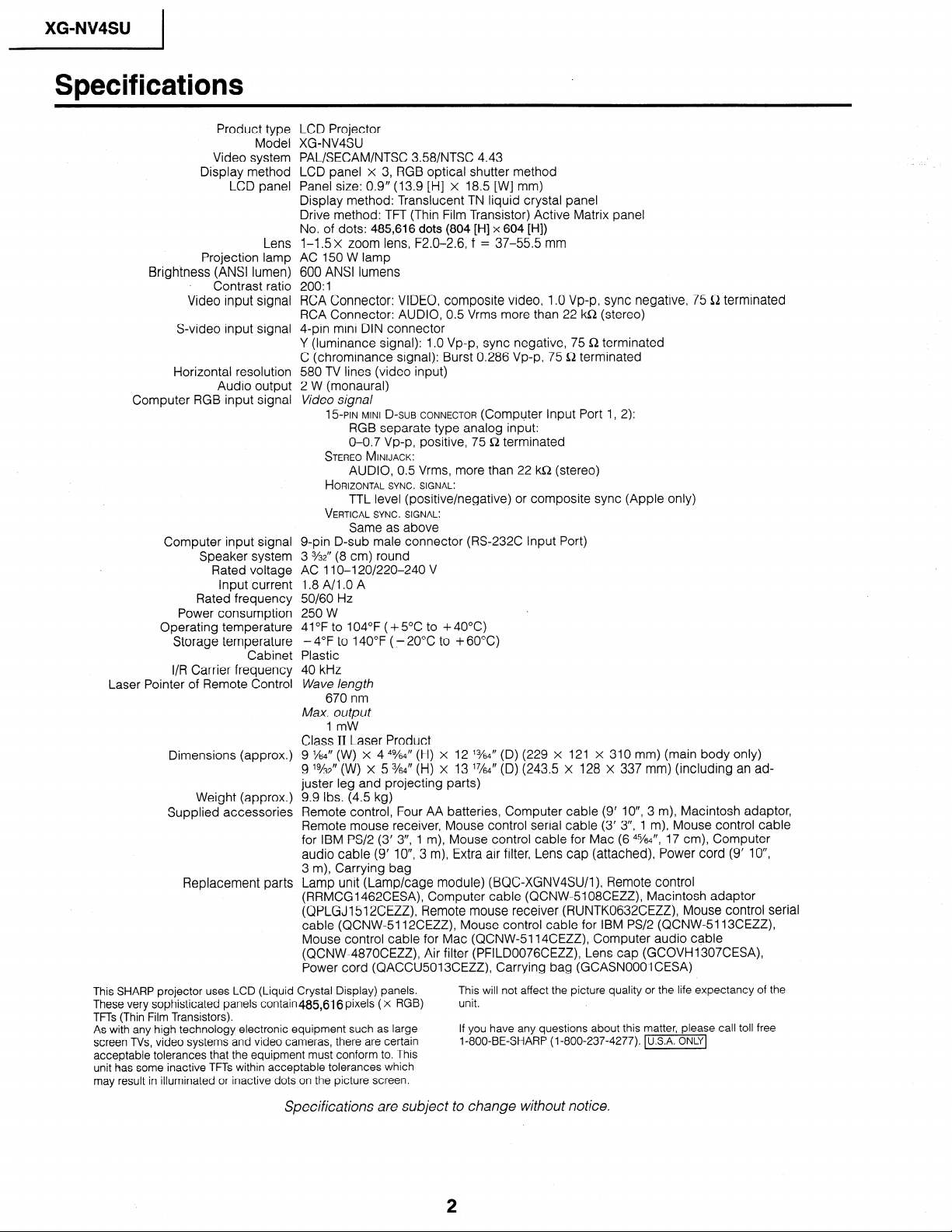
This SHARP projector uses LCD (Liquid Crystal Display) panels.
These very sophisticated panels contain4&616 pixels ( x RGB)
TFTs (Thin Film Transistors).
As with any high technology electronic equipment such as large
screen TVs, video systems and video cameras, there are certain
acceptable tolerances that the equipment must conform to. This
unit has some inactive TFTs within acceptable tolerances which
may result in illuminated or inactive dots on the picture screen.
Product type LCD Projector
Model XG-NV4SU
Video system
LCD panel
Audio output
Rated voltage
Input current
Cabinet
PAL/SECAM/NTSC 358/NTSC 4.43
LCD panel x 3, RGB optical shutter method
Panel size: 0.9” (13.9 [H] x 18.5 [W] mm)
Display method: Translucent TN liquid crystal panel
Drive method: TFT (Thin Film Transistor) Active Matrix panel
No. of dots: 485,616 dots (804 [H] x 604 [HI)
l-l .5x zoom lens, F2.0-2.6, f = 37-55.5 mm
Lens
AC 150 W lamp
600 ANSI lumens
200: 1
RCA Connector: VIDEO, composite video, 1 .O Vp-p, sync negative, 75 a terminated
RCA Connector: AUDIO, 0.5 Vrms more than 22 ka (stereo)
4-pin mini DIN connector
Y (luminance signal): 1 .O Vp-p, sync negative, 75 fi terminated
C (chrominance signal): Burst 0.286 Vp-p, 75 a terminated
580 TV lines (video input)
2 W (monaural)
Video signal
15-PIN MINI D-SUB CONNECTOR (Computer Input Port 1, 2):
RGB separate type analog input:
O-O.7 Vp-p, positive, 75 Q terminated
STEREO MINIJACK:
AUDIO, 0.5 Vrms, more than 22 kfi (stereo)
HORIZONTAL SYNC. SIGNAL:
TTL level (positive/negative) or composite sync (Apple only)
VERTICAL SYNC. SIGNAL:
g-pin D-sub male connector (RS-232C Input Port)
3 3/32” (8 Cm> round
AC 11 O-l 20/220-240 V
1.8 A/l .O A
50/60 Hz
250 W
41 OF to 104°F ( + 5OC to + 40°C)
Plastic
40 kHz
Wave length
Max. output
Class II Laser Product
9 x4” (w) X 4 4%4” (H) X 12 %4” (D) (229 X 121 X 310 mm) (main body Only)
9 ‘%2” (W) X 5 %4” (H) X 13 ‘x4” (D) (243.5 X 128 X 337 mm) (including an ad-
juster leg and projecting parts)
9.9 Ibs. (4.5 kg)
Remote control, Four AA batteries, Computer cable (9’ IO”, 3 m), Macintosh adaptor,
Remote mouse receiver, Mouse control serial cable (3’ 3”, 1 m), Mouse control cable
for IBM PS/2 (3’ 3”, 1 m), Mouse control cable for Mac (6 4%4”, 17 cm), Computer
audio cable (9’ IO”, 3 m), Extra air filter, Lens cap (attached), Power cord (9’ IO”,
3 m), Carrying bag
Lamp unit (Lamp/cage module) (BQC-XGNV4SU/l), Remote control
(RRMCGI 462CESA), Computer cable (QCNW-5108CEZZ), Macintosh adaptor
(QPLGJI 512CEZZ), Remote mouse receiver (RUNTK0632CEZZ) Mouse control serial
cable (QCNW-5112CEZZ), Mouse control cable for IBM PS/2 (QCNW-5113CEZZ),
Mouse control cable for Mac (QCNW-5114CEZZ), Computer audio cable
(QCNW-4870CEZZ) Air filter (PFILD0076CEZZ), Lens cap (GCOVH1307CESA),
Power cord (QACCU5013CEZZ), Carrying bag (GCASNOOOI CESA)
Same as above
- 4°F to 1 40°F ( - 20°C to + 60°C)
670 nm
1 mW
This will not affect the picture quality or the life expectancy of the
unit.
If you have any questions about this matter, please call toll free
1-800-BE-SHARP (l-800-237-4277). -1
Specifications are subject to change without notice.
IMPORTANT SERVICE
XG-NV4SU
I
n Service work should be performed only by
thoroughly familiar with all safety checks and
WARNING
1. For continued safety, no modification of any circuit
should be attempted.
2. Disconnect AC power before servicing.
BEFORE RETURNING THE PROJECTOR:
(Fire 81 Shock Hazard)
Before returning the projector to the user, perform
the following safety checks:
1 .
Inspect lead wires are not pinched between the
chassis and other metal parts of the projector.
.
2
Inspect all protective devices such as non-metallic
control knobs, insulating materials, cabinet backs,
adjustment and compartment covers or shields,
isolation resistor-capacity networks, mechanical
insulators, etc.
.
3
To be sure that no shock hazard exists, check for
current leakage in the following manner:
0
Plug the AC cord directly into a 120~volt AC outlet,
(Do not use an isolation transformer for this test).
0
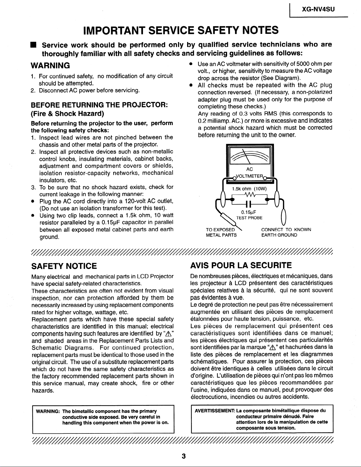
Using two clip leads, connect a 1.5k ohm, 10 watt
resistor paralleled by a 0.15uF capacitor in parallel
between all exposed metal cabinet parts and earth
ground.
0
0
qualified service technicians who are
servicing guidelines as follows:
Use an AC voltmeter with sensitivity of 5000 ohm per
volt., or higher, sensitivity to measure the AC voltage
drop across the resistor (See Diagram).
All checks must be repeated with the AC plug
connection reversed. (If necessary, a non-polarized
adapter plug must be used only for the purpose of
completing these checks.)
Any reading of 0.3 volts RMS (this corresponds to
0.2 milliamp. AC.) or more is excessive and indicates
a potential shock hazard which must be corrected
before returning the unit to the owner.
1.5k ohm (1 OW)
0.15pF
TEST PROBE
TOEXPOSED\
METAL PARTS
CONNECT TO KNOWN
EARTH GROUND
SAFETY NOTICE
Many electrical and mechanical parts in LCD Projector
have special safety-related characteristics.
These characteristics are often not evident from visual
inspection, nor can protection afforded by them be
necessarily increased by using replacement components
rated for higher voltage, wattage, etc.
Replacement parts which have these special safety
characteristics are identified in this manual; electrical
components having such features are identified by “A”
and shaded areas in the Replacement Parts Lists and
Schematic Diagrams.
replacement parts must be identical to those used in the
original circuit. The use of a substitute replacement parts
which do not have the same safety characteristics as
the factory recommended replacement parts shown in
this sewice manual, may create shock, fire or other
hazards.
WARNING: The bimetallic component has the primary
conductive side exposed. Be very careful in
handling this component when the power is on.
For continued protection,
AVIS POUR LA SECURITE
De nombreuses pieces, electriques et mecaniques, dans
les projecteur a LCD presentent des caracteristiques
speciales relatives a la securite, qui ne sont souvent
pas evidentes a vue.
Le degre de protection ne peut pas etre necessairement
augmentee en utilisant des pieces de remplacement
etalonnees pour haute tension, puissance, etc.
Les pieces de remplacement qui presentent ces
caracteristiques sont identifiees dans ce ‘manuel;
les pieces electriques qui presentent ces particularites
sont identifiees par la marque “A” et hachurees dans la
liste des pieces de remplacement et les diagrammes
schematiques. Pour assurer la protection, ces pieces
doivent etre identiques a celles utilisees dans le circuit
d’origine. L’utilisation de pieces qui n’ont pas les memes
caracteristiques que les pieces recommandees par
I’usine, indiquees dans ce manuel, peut provoquer des
electrocutions, incendies ou autres accidents.
AVERTISSEMENT: La composante bim6tallique dispose du
conducteur primaire denude. Faire
attention lors de la manipulation de cette
composante sous tension.
3

XG-NV4SU
I
NOTE TO SERVICE
PERSONNEL
////////////////////////////////////////
UV-RADIATION PRECAUTION
////////////////////////////////////////
The light source,
projector emits small amounts of UV-Radiation.
AVOID DIRECT EYE AND SKIN EXPOSURE.
To ensure safety please adhere to the following:
metal halide lamp, in the LCD
-
PRECAUTION POUR LES RADIATIONS UV
‘///////////////////
La source de lumiere, la lampe metal halide, dans le
projecteur LCD emet de petites quantites de
radiation UV.
EVITEZ TOUTE EXPOSITION DIRECTE
DES YEUX ET DE LA PEAU.
Pour votre securite, nous vous prions de respecter
les points suivants:
1. Be sure to wear sun-glasses
projector with the lamp
turned “on” and the top
enclosure removed.
2. Do not operate the lamp outside of the lamp housing.
3. Do not operate for more than 2 hours with the
enclosure removed.
when servicing the
1. Toujours porter des lunettes de soleil lors d’un
entretien du projecteur
avec la lampe allumee
et le haut du coffret retire.
2. Ne pas faire fonctionner la lampe a I’exterieur du
bolttier de lampe.
3. Ne pas faire fonctionner plus de 2 heures avec le
coff ret retire.
UV-Radiation and Medium Pressure
Lamp Precautions
1 .
Be sure to disconnect the AC plug when replacing
the lamp.
2 .
Allow one hour for the unit to cool down before
servicing.
.
Replace only with same type lamp. Type
3
CLMPFOOZDEOl or BQCXGNV4SU/l rated 65V/
15ow.
4 .
The lamp emits small amounts of UV-Radiation, avoid
direct-eye contact.
.
5
The medium pressure lamp involves a risk of
explosion. Be sure to follow installation instructions
described below and handle the lamp with care.
Prhcautions pour les
et la lampe moyenne
1 .
Toujours debrancher la
remplacement de la lampe.
2 .
Laisser I’unite refroidir pendant une heure avant de
proceder a I’entretien.
3 .
Ne remplacer qu’avec une lampe du meme type.
Type CLMPF0055DEOl or BQCXGNV4SUI1,
caracteristique,65V/15OW.
4 .
La lampe emet de petites quantites de radiation UVeviter tout contact direct avec les yeux.
.
La lampe moyenne pression implique un risque
5
d’explosion. Toujours suivre les instructions
d’installation d&rites ci-dessous et manipuler la
lampe avec soin.
radiations UV
pression
fiche AC lors du
1
1 XG-NV4SU
c
UV-RADIATION PRECAUTION (Continued)
////////////////////
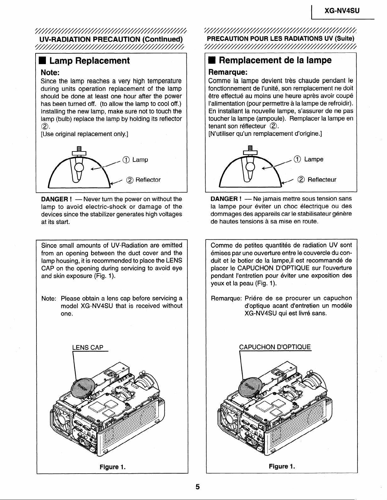
W Lamp Replacement
Note:
Since the lamp reaches a very high temperature
during units operation replacement of the lamp
should be done at least one hour after the power
has been turned off. (to allow the lamp to cool off.)
Installing the new lamp, make sure not to touch the
lamp (bulb) replace the lamp by holding its reflector
0
[Use original replacement only.]
/@ Lamp
@
DANGER !
lamp to avoid electric-shock or damage of the
devices since the stabilizer generates high voltages
at its start.
- Never turn the power on without the
\J
@ Reflector
I
PRECAUTION POUR LES RADIATIONS UV (Suite)
5///////////////////////////////////////
n Remplacement de la lampe
Remarque:
Comme la lampe devient tres chaude pendant le
fonctionnement de I’unite, son remplacement ne doit
etre effectue au moins une heure apres avoir coupe
I’alimentation (pour permettre a la lampe de refroidir).
En installant la nouvelle lampe, s’assurer de ne pas
toucher la lampe (ampoule). Remplacer la lampe en
tenant son reflecteur 0.
[N’utiliser qu’un remplacement d’origine.]
/ @ Lampe
@ Reflecteur
3
DANGER ! - Ne jamais mettre sous tension sans
la lampe pour eviter un choc electrique ou des
dommages des appareils car le stabilisateur genere
de hautes tensions a sa mise en route.
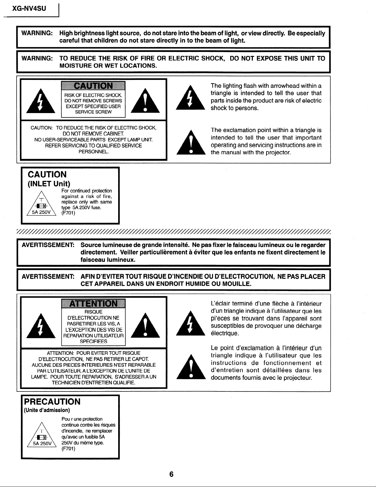
Since small amounts of UV-Radiation are emitted
from an opening between the duct cover and the
lamp.housing, it is recommended to place the LENS
CAP on the opening during servicing to avoid eye
and skin exposure (Fig. 1).
Note: Please obtain a lens cap before servicing a
model XG-NV4SU that is received without
one.
LENS CAP
Comme de petites quantites de radiation UV sont
emises par une ouverture entre le couvercle du conduit et le botier de la lampe,il est recommande de
placer le CAPUCHON D’OPTIQUE sur I’ouverture
pendant I’entretien pour eviter une exposition des
yeux et la peau (Fig. 1).
Remarque: Priere de se procurer un capuchon
d’optique acant d’entretien un modele
XG-NV4SU qui est livre sans.
CAPUCHON D’OPTIQUE
Figure 1.
Figure 1.
XG-NV4SU
WARNING: High brightness light source, do not stare into the beam of light, or view directly. Be especially
WARNING: TO REDUCE THE RISK OF FIRE OR ELECTRIC SHOCK, DO NOT EXPOSE THIS UNIT TO
I
careful that children do not stare directly in to the beam of light.
MOISTURE OR WET LOCATIONS.
The lighting flash with arrowhead within a
RISK OF ELECTRIC SHOCK.
DO NOT REMOVE SCREWS
EXCEPT SPECIFIED USER
SERVICE SCREW
A
triangle is intended to tell the user that
parts inside the product are risk of electric
shock to persons.
CAUTION: TO REDUCE THE RISK OF ELECTRIC SHOCK,
DO NOT REMOVE CABINET
NO USER-SERVICEABLE PARTS EXCEPT LAMP UNIT
REFER SERVICING TO QUALIFIED SERVICE
PERSONNEL.
A
The exclamation point within a triangle is
intended to tell the user that important
operating and servicing instructions are in
the manual with the projector.
CAUTION
(INLET Unit)
AVERTISSEMENT: Source lumineuse de grande intensite. Ne pas fixer le faisceau lumineux ou le regarder
AVERTISSEMENT: AFIN D’EVITER TOUT RISQUE D’INCENDIE OU D’ELECTROCUTION, NE PAS PLACER
I
D’ELECTROCUTION, NE PAS RETIRER LE CAPOT.
AUCUNE DES PIECES INTERIEURES N’EST REPARABLE
PAR L’UTILISATEUR, A CEXCEPTION DE L’UNITE DE
LAMPE. POUR TOUTE REPARATION, S’ADRESSER A UN
For continued protection
against a risk of fire,
replace only with same
type 5A 250V fuse.
WI)
directement. Veiller particulierement a eviter que les enfants ne fixent directement le
faisceau lumineux.
CET APPAREIL DANS UN ENDROIT HUMIDE OU MOUILLE.
~
.z. .;.;.:.; ::;z: -.f55: ::.
. A.. v.-.Y.* *.y. 5. v.*.-. . ::::.
-.-.~.v.*.-.v. . . . ., . . h . A555
D’ELECTROCUTION NE
PASRETIRER LES VIS, A
L’EXCEPTION DES VIS DE
REPARATION UTILISATEUR
ATTENTION: POUR EVITER TOUT RISQUE
TECHNICIEN D’ENTRETIEN QUALIFIE.
, ; . .&:. . .:p . . :.y . . &.. .
. .
RISQUE
SPECIFIEES
A
A
C&lair termine d’une fleche a l’interieur
d’un triangle indique a I’utilisateur que les
pi‘eces se trouvant dans I’appareil sont
susceptibles de provoquer une decharge
electrique.
Le point d’exclamation a I’interieur d’un
triangle indique a I’utilisateur que les
instructions, de fonctionnement et
d’entretien sont detaillees dans les
documents fournis. avec le projecteur.
I
PRECAUTION
(Unite d’admission)
Pou r une protection
continue contre les risques
d’incendie, ne remplacer
qu’avec un fusible 5A
250V du meme type.
(noI )
6
Location of Controls
I
XG-NV4SU
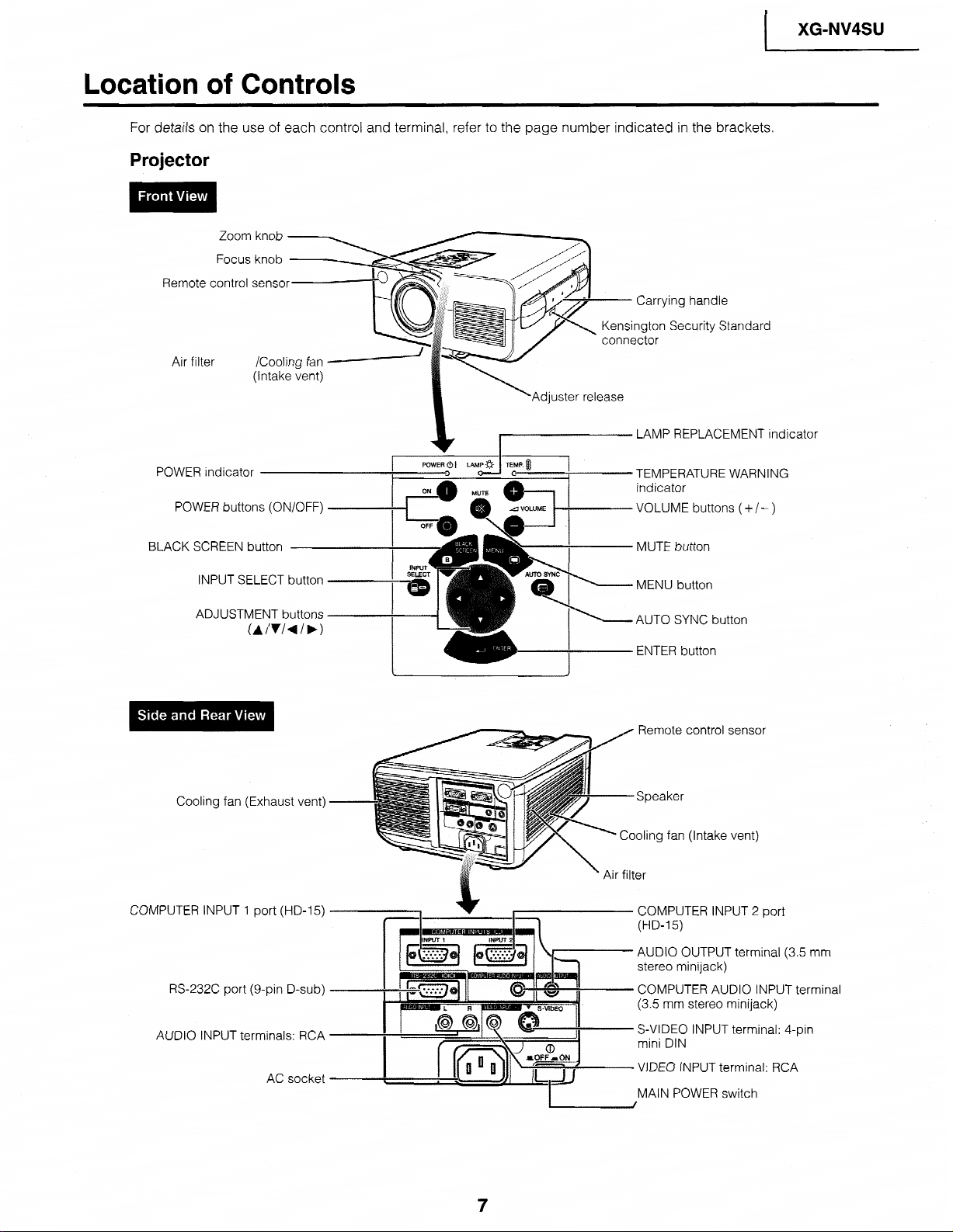
For details on the use of each
Projector
Zoom knob
Focus knob
Remote control senso
Air filter /Cooling fan
(Intake vent)
POWER indicator
POWER buttons (ON/OFF)
BLACK SCREEN button
INPUT SELECT button
control and terminal, refer to the
_j-
I LAMP REPLACEMENT
page number indicated in the brackets.
,ing handle
Security Standard
djuster release
TEMPERAT\ JRF WARNING
indicator
VOLUME buttons
MUTE button
(+/-)
ind
icator
ADJUSTMENT buttons
Cooling fan (Exhaust vent)
CCIMPI JTFR INPl IT 1
RS-232C port (g-pin D-sub)
AUDIO INPUT terminals: RCA -
not-t (I-ID-15)
AC socket
I
I Irn
ENTER button
Remote control sensor
Speaker
Cooling fan (Intake vent)
COMPUTER INPUT 2 port
AUDIO OUTPUT terminal (3.5 r-r
f il:_r stereo minijack)
COMPUTER AUDIO INPUT tern
(3.5 mm stereo minijack)
S-VIDEO INPUT terminal: 4-pin
mini DIN
VIDEO INPUT terminal: RCA
MAIN POWER switch
7m
iinal
XG-NV4SU
Operating the Wireless Mouse Remote Control
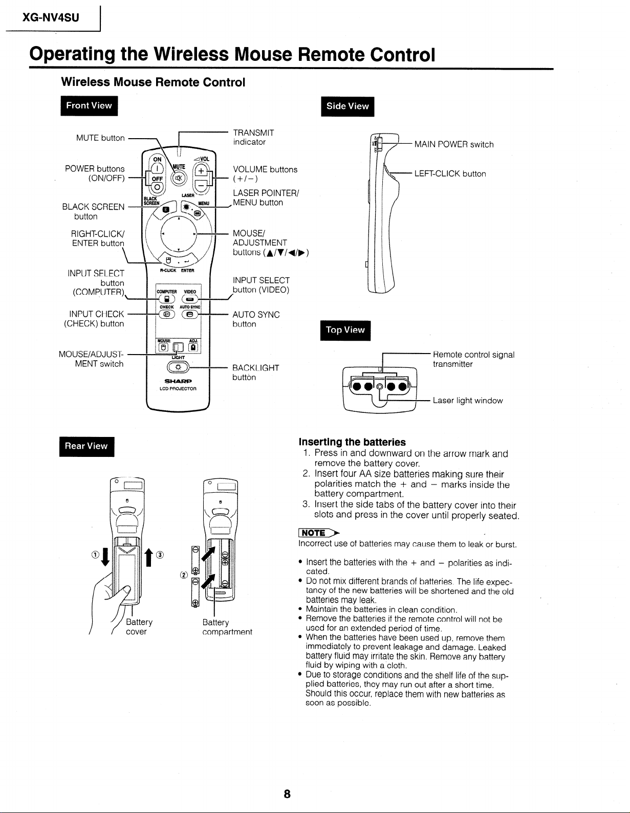
Wireless Mouse Remote Control
MAIN POWER switch
POWER buttons
RIGHT-CLICK/
ENTER button
INPUT SELECT
(COMPUTER),
INPUT CHECK -
(CHECK) button
MOUSE/ADJUST- -
MENT switch
\ \ w/ buttons (A/V/d/b)
button
f+iix
G\IIMo
I
-“=cz>~” /
CXECK RUT0 SYNC
--coz) a----
Si-tARP
LCD PROJECTOR
I
l I
I I
LASER POINTER/
ADJUSTMENT
INPUT SELECT
button (VIDEO)
AUTO SYNC
button
BACKLIGHT
button
LEFT-CLICK button
Remote control signal
transmitter
Laser light window
Inserting the batteries
1, Press in and downward on the arrow mark and
remove the battery cover.
2. Insert four AA size batteries making sure their
polarities match the + and - marks inside the
battery compartment.
3. Insert the side tabs of the battery cover into their
slots and press in the cover until properly seated.
Battery
compartment
Incorrect use of batteries may cause them to leak or burst.
l Insert the batteries with the + and - polarities as indi-
cated.
l Do not mix different brands of batteries. The life expec-
tancy of the new batteries will be shortened and the old
batteries may leak.
l Maintain the batteries in clean condition.
l Remove the batteries if the remote control will not be
used for an extended period of time.
l When the batteries have been used up, remove them
immediately to prevent leakage and damage. Leaked
battery fluid may irritate the skin. Remove any battery
fluid by wiping with a’cloth.
l Due to storage conditions and the shelf life of the sup-
plied batteries, they may run out after a short time.
Should this occur, replace them with new batteries as
soon as possible.
8
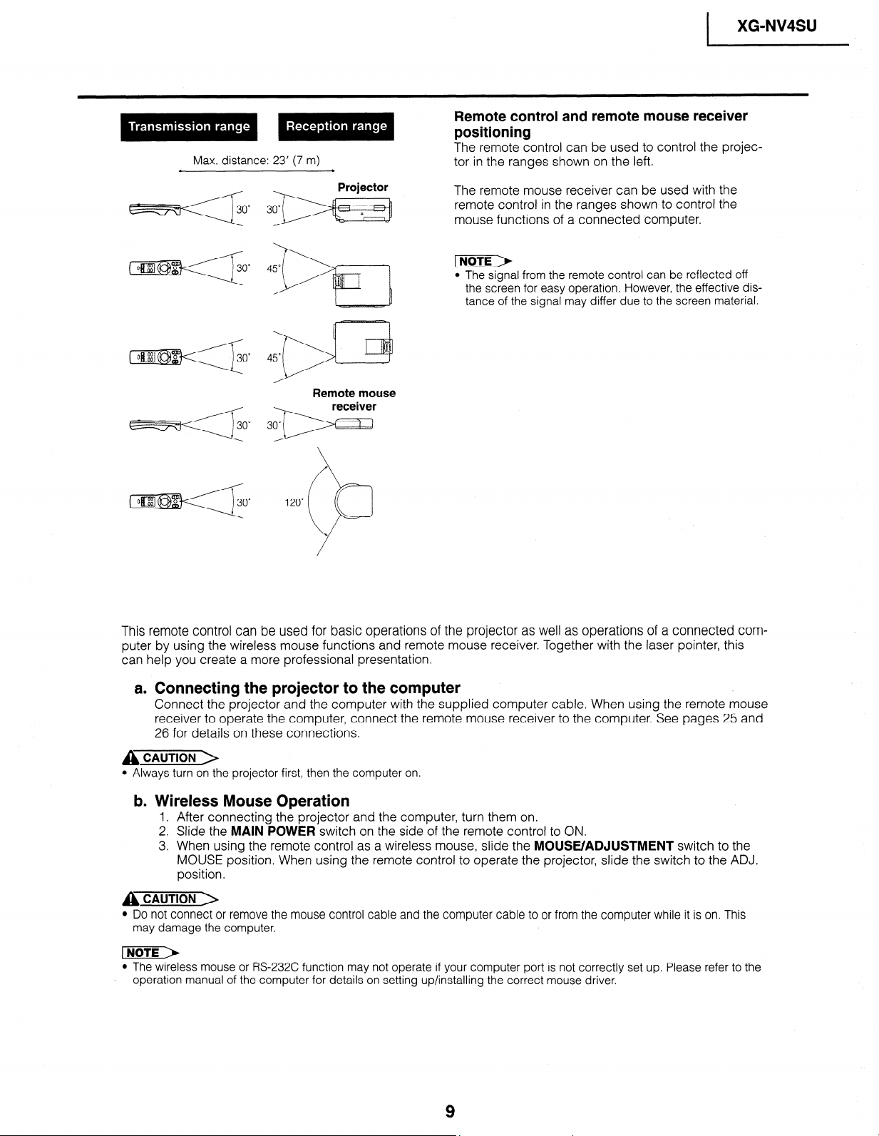
Max. distance: 23’ (7 m)
XG-NV4SU
I
Remote control and remote mouse receiver
positioning
The remote control can be used to control the projector in the ranges shown on the left.
Projector
cz!EE3T~O~ 3om DI y-j
Remote mouse
The remote mouse receiver can be used with the
remote control in the ranges shown to control the
mouse functions of a connected computer.
l The signal from the remote control can be reflected off
the screen for easy operation, However, the effective distance of the signal may differ due to the screen material.
This remote control can be used for basic operations of the projector as well as operations of a connected computer by using the wireless mouse functions and remote mouse receiver. Together with the laser pointer, this
can help you create a more professional presentation.
a. Connecting the projector to the computer
Connect the projector and the computer with the supplied computer cable. When using the remote mouse
receiver to operate the computer, connect the remote mouse receiver to the computer. See pages 25 and
26 for details on these connections.
A CAUTION >
l Always turn on the projector first, then the computer on.
b. Wireless Mouse Operation
1. After connecting the projector and the computer, turn them on.
2. Slide the MAIN POWER switch on the side of the remote control to ON.
3. When using the remote control as a wireless mouse, slide the MOUSE/ADJUSTMENT switch to the
MOUSE position. When using the remote control to operate the projector, slide the switch to the ADJ.
position.
A CAUTION >
l Do not connect or remove the mouse control cable and the computer cable to or from the computer while it is on. This
may damage the computer.
l The wireless mouse or RS-232C function may not operate if your computer port is not correctly set up. Please refer to the
. operation manual of the computer for details on setting up/installing the correct mouse driver.
9
_ XG-NV4SU )
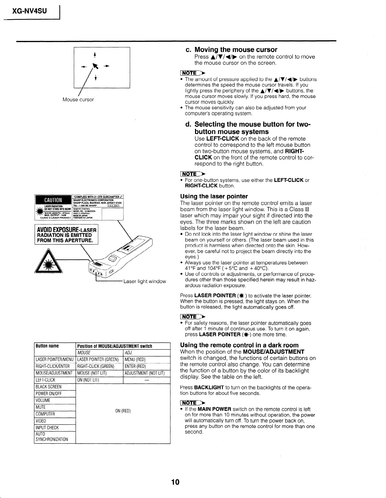
Mouse cursor
c. Moving the mouse cursor
Press A/V/+/, on the remote control to move
the mouse cursor on the screen.
l The amount of pressure applied to the A/V/+/, buttons
determines the speed the mouse cursor travels. If you
lightly press the periphery of the A/V/+/, buttons, the
mouse cursor moves slowly. If you press hard, the mouse
cursor moves quickly.
l The mouse sensitivity can also be adjusted from your
computer’s operating system.
d. Selecting the mouse button for two-
button. mouse systems
Use LEFT-CLICK on the back of the remote
control to correspond to the left mouse button
on two-button mouse systems, and RIGHTCLICK on the front of the remote control to correspond to the right button.
l For one-button systems, use either the LEFT-CLICK or
RIGHT-CLICK button.
L-----Laser
Button name
LASERPOINTER/MENU LASER POINTER(GREEN) MENU(RED)
1 RIGHT-CLICK/ENTER 1 RIGHT-CLICK(GREEN)
MOUSE/ADJUSTMENT MOUSE(NOTLIT)
LEFT-CLICK ON (NOT LIT)
(BLACKSCREEN 1
Position of MOUSE/ADJUSTMENT switch
MOUSE
light window
ADJ.
1 ENTER(RED)
ADJUSTMENT(NOTLIT)
-
Using the laser pointer
The laser pointer on the remote control emits a laser
beam from the laser light window. This is a Class II
laser which may impair your sight if directed into the
eyes. The three marks shown on the left are caution
labels for the laser beam.
l Do not look into the laser light window or shine the laser
beam on yourself or others. (The laser beam used in this
product is harmless when directed onto the skin. However, be careful not to project the beam directly into the
eyes.)
l Always use the laser pointer at temperatures between
41 OF and 104°F ( + 5OC and + 40°C).
l Use of controls or adjustments, or performance of proce-
dures other than those specified herein may result in hazardous radiation exposure.
Press LASER POINTER (#) to activate the laser pointer.
When the button is pressed, the light stays on. When the
button is released, the light automatically goes off.
l For safety reasons, the laser pointer automatically goes
off after 1 minute of continuous use. To turn it on again,
press LASER POINTER (*) one more time.
Using the remote control in a dark room
When the position of the MOUSE/ADJUSTMENT
switch is changed, the functions of certain buttons on
the remote control also change. You can determine
the function of a button by the color of its backlight
display. See the table on the left,
Press BACKLIGHT to turn on the backlights of the operation buttons for about five seconds.
SYNCHRONIZATION
ON(RED)
l If the MAIN POWER switch on the remote control is left
on for more than 10 minutes without operation, the power
will automatically turn off. To turn the power back on,
press any button on the remote control for more than one
second.
10
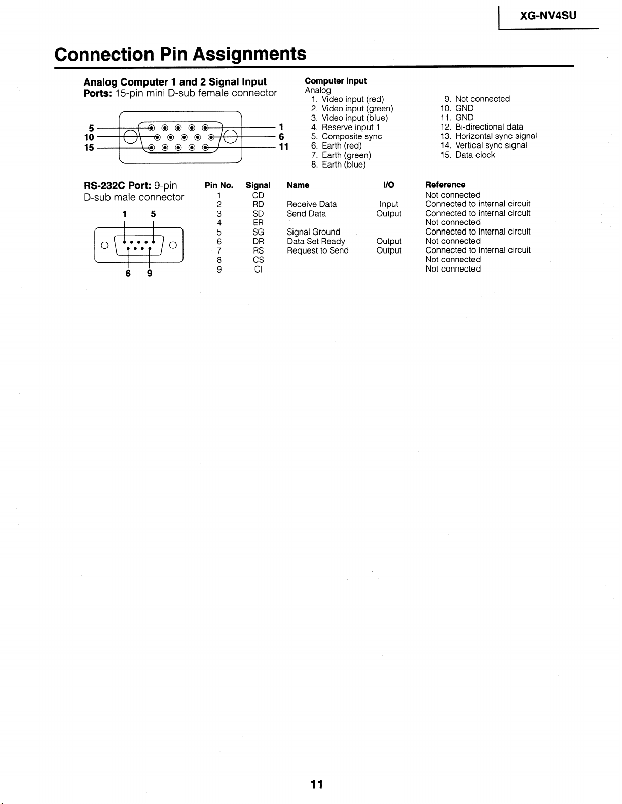
Connection Pin Assignments
XG-NV4SU
I
Analog Computer 1 and 2 Signal Input
Ports: E-pin mini D-sub female connector
5
IO
15
RS-232C Port: g-pin
D-sub male connector
1 5
0.0
0
00
0
s
6 9
Pin No. Signal
1
2 RD
3
4 ER
5
6 DR
7 RS
8
9
CD
SD
SG
cs
Cl
Computer Input
Analog
1. Video input (red)
2. Video input (green)
3. Video input (blue)
4. Reserve input
5. Composite sync
6. Earth (red)
7. Earth (green)
8. Earth (blue)
Name
Receive Data Input
Send Data output
Signal Ground
Data Set Ready output
Request to Send output
1
I/O
9. Not connected
10. GND
11. GND
12. Bi-directional data
13. Horizontal sync signal
14. Vertical sync signal
15. Data clock
Reference
Not connected
Connected to internal circuit
Connected to internal circuit
Not connected
Connected to internal circuit
Not connected
Connected to internal circuit
Not connected
Not connected
11
XG-NV4SU
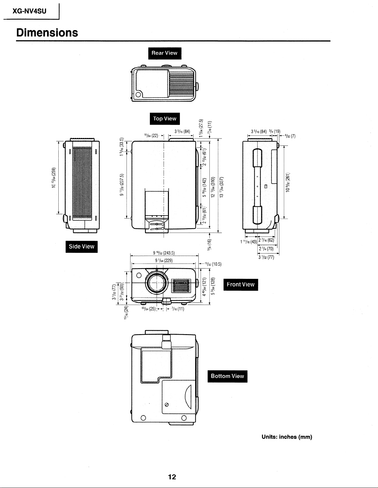
Dimensions
55/64 (22)-/
63/64 (25) fl /- 7/16 (11)
xi
CD
<
z
9 "/32 (243.5)
9 '/64 (229)
II
3 5/16 (84)
13/32 (10.5)
3 5/16 (84) 3/4 1
P
3 l/32 (77)
‘132 (7)
12
Units: inches (mm)
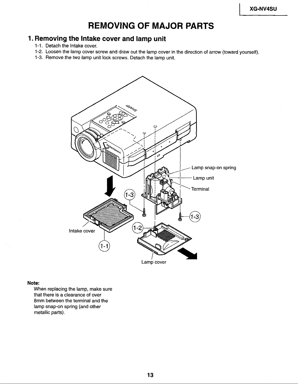
REMOVING OF MAJOR PARTS
)
XG-NV4SU
1. Removing the Intake
l-l. Detach the
l-2. Loosen
l-3.
Remove the two lamp
Intake
cover.
the lamp cover screw and draw
unit lock screws.
cover and lamp
out the
Detach
lamp cover in the direction of arrow (toward yourself).
the lamp unit.
unit
#on spring
Note:
When replacing the lamp, make sure
that there is a clearance of over
8mm between the terminal and the
lamp snap-on spring (and other
metallic parts).
Lamp cover
13
XG-NV4SU
I
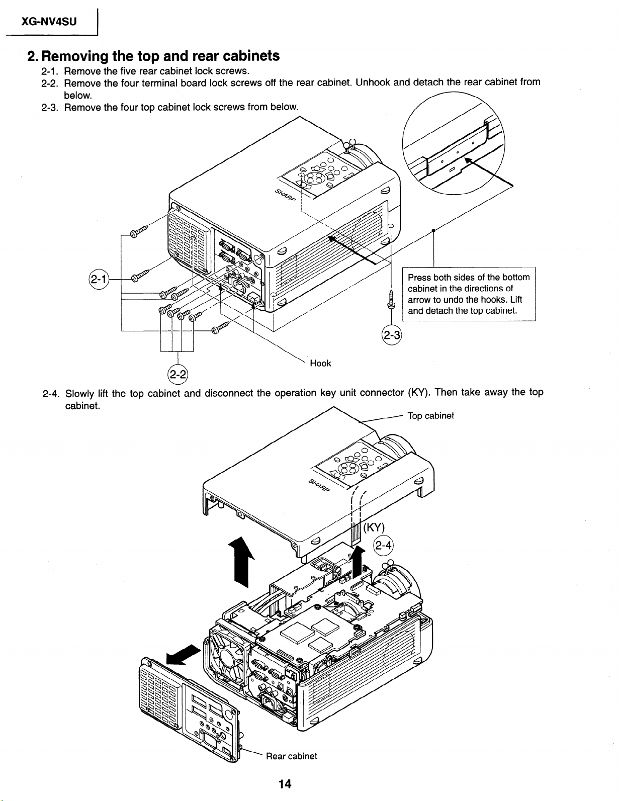
2. Removing the top and rear cabinets
2-1. Remove the five rear cabinet lock screws.
2-2. Remove the four terminal board lock screws off the rear cabinet. Unhook and detach the rear cabinet from
below.
2-3. Remove the four top cabinet lock screws from below.
0
0
0
fl
I
/
Press both sides of the bottom
cabinet in the directions of
arrow to undo the hooks. Lift
and detach the top cabinet.
24 - . Slowly lift
cabinet.
\
. Hook
th e top cabinet and disconnect the operation key unit connector
7 Topcat
(KY). Then take away the top
Snet
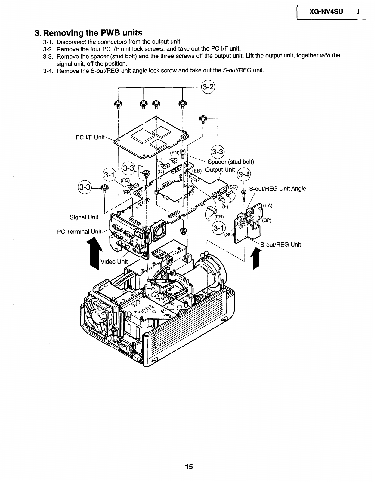
3. Removing the PWB units
3-1. Disconnect the connectors from the output unit.
3-2. Remove the four
3-3.
Remove the spacer (stud bolt) and the three screws off the output unit. Lift the
signal unit, off the
3-4. Remove the S-out/REG unit angle lock screw and take out the S-out/REG unit.
PC I/F Unit
PC I/F unit lock screws, and take out the
position.
PC I/F unit.
(stud
bolt)
XG=NV4SU J
I
output unit, together with the
PC1
.S-nl
It/R EG
Unit Angle
IEG Unit
15
XG-NV4SU
I
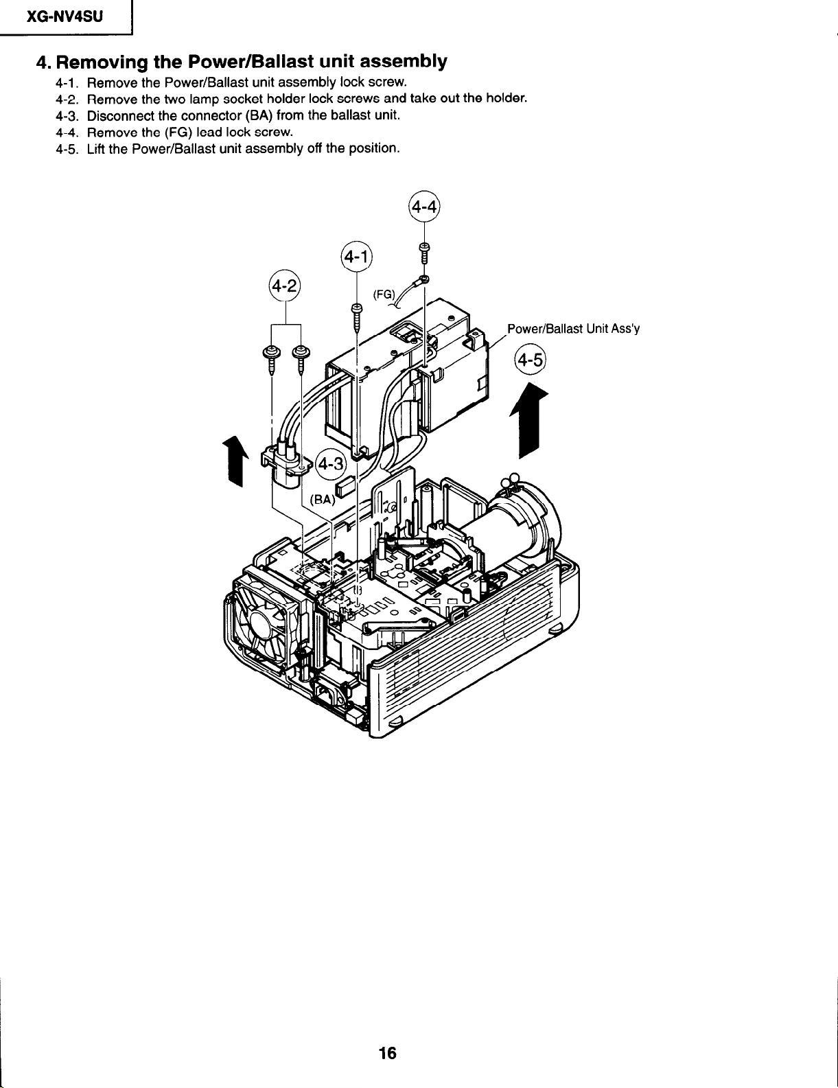
4. Removing the Power/Ballast unit assembly
4-l. Remove the Power/Ballast unit assembly lock screw.
4-2. Remove the two lamp socket holder lock screws and take out the holder.
4-3. Disconnect the connector (BA) from the ballast unit.
4-4. Remove the (FG) lead lock screw.
4-5. Lift the Power/Ballast unit assembly off the position.
Unit
Ass’y
16
I
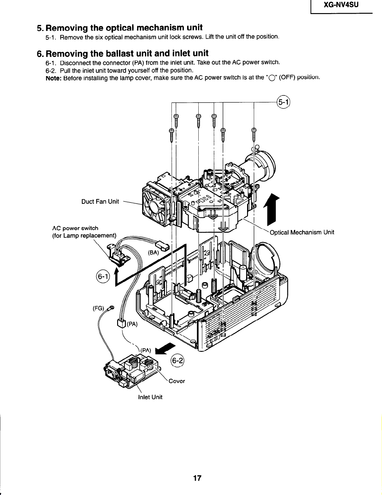
5. Removing the optical mechanism unit
5-l. Remove the six optical mechanism unit lock screws. Lift the unit off the position.
6. Removing the ballast unit and inlet unit
6-l. Disconnect the connector (PA) from the inlet unit. Take out the AC power switch.
6-2. Pull the inlet unit toward yourself off the position.
Note: Before installing the lamp cover, make sure the AC power switch is at the “0 (OFF) position.
XG-NV4SU
Duct Fan Unit
AC power switch
(for Lamp replacement)
Optical Mechanism Unit
Inlet Unit
17
XG-NV4SU
I
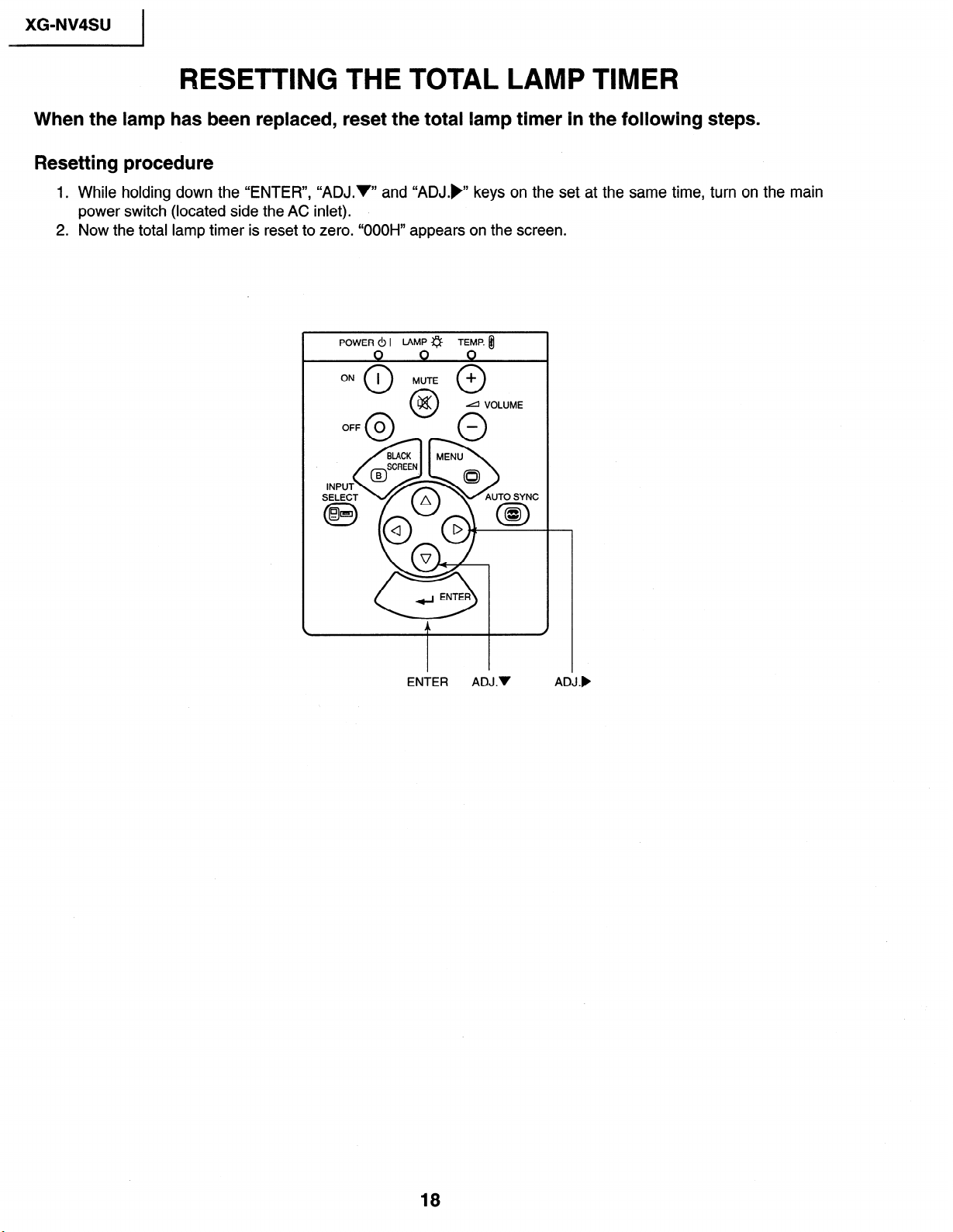
RESETTING THE TOTAL LAMP TIMER
When the lamp has been replaced, reset the total lamp timer in the following steps.
Resetting procedure
1. While holding down the “ENTER”, “ADJ.V” and “ADJ.),’ keys on the set at the same time, turn on the main
power switch (located side the AC inlet).
2. Now the total lamp timer is reset to zero. “OOOH” appears on the screen.
POWER 0 I LAMP a
ENTER ADJ.V
TEMP. fil
d VOLUME
ADJ.)
18

THE OPTICAL UNIT OUTLINE
Layout of the optical system
Note: Layout for positioning the optical system.
Incident polarizing plate B
\
Projection Lens
Incident polarizing plate R
Dichroic coating
(R transmission)
XG-NV4SU
I
--
* The M3 mirrors have a coating
wedge (for different film thick-
ness). Set up these mirrors, with
their markings positioned as
shown above, so that their
coated faces and both sides be
in the correct directions.
V 1 Relay lens 1
AL-deposited face
(Light source)
AC lamp
Dichroic coating
I/
PBS(polarization
I’
1;
I
1;
I /
I /
I/
L.’
I’
1;
I
I
I
I
I
I
I 11
1
- Fly-eye lens (outgoing light)
- Fly-eye lens (incoming light)
- UV-IR filter
face
” PBS aperture
19
P
A
oF
9
XG-NV4SU
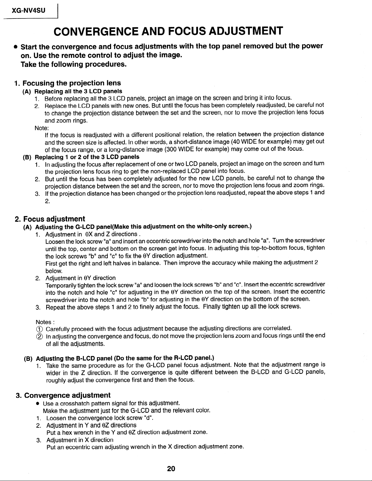
CONVERGENCE AND FOCUS ADJUSTMENT
Start the convergence and focus adjustments with the top panel removed but the power
on. Use the remote control to adjust the image.
Take the following procedures.
.
Focusing the projection lens
(A) Replacing all the 3 LCD panels
1. Before replacing all the 3 LCD panels, project an image on the screen and bring it into focus.
2. Replace the LCD panels with new ones. But until the focus has been completely readjusted, be careful not
to change the projection distance between the set and the screen, nor to move the projection lens focus
and zoom rings.
Note:
If the focus is readjusted with a different positional relation, the relation between the projection distance
and the screen size is affected. In other words, a short-distance image (40 WIDE for example) may get out
of the focus range, or a long-distance image (300 WIDE for example) may come out of the focus.
(B) Replacing 1 or 2 of the 3 LCD panels
1. In adjusting the focus after replacement of one or two LCD panels’ project an image on the screen and turn
the projection lens focus ring to get the non-replaced LCD panel into focus.
2. But until the focus has been completely adjusted for the new LCD panels, be careful not to change the
projection distance between the set and the screen, nor to move the projection lens focus and zoom rings.
3. If the projection distance has been changed or the projection lens readjusted, repeat the above steps 1 and
2 .
r. Focus adjustment
(A) Adjusting the G-LCD panel(Make this adjustment on the white-only screen.)
1 .
Adjustment in 8X and Z directions .
Loosen the lock screw “a” and insert an eccentric screwdriver into the notch and hole “a”. Turn the screwdriver
until the top, center and bottom on the screen get into focus. In adjusting this top-to-bottom focus, tighten
the lock screws “b” and “c” to fix the 0Y direction adjustment.
First get the right and left halves in balance. Then improve the accuracy while making the adjustment 2
below.
.
Adjustment in 8Y direction
2
Temporarily tighten the lock screw “a” and loosen the lock screws “b” and “c”. Insert the eccentric screwdriver
into the notch and hole “c” for adjusting in the 8Y direction on the top of the screen. Insert the eccentric
screwdriver into the notch and hole “b” for adjusting in the 8Y direction on the bottom of the screen.
.
Repeat the above steps 1 and 2 to finely adjust the focus.
3
Notes :
@ Carefully proceed with the focus adjustment because the adjusting directions are correlated.
@ In adjusting the convergence and focus, do not move the projection lens zoom and focus rings until the end
of all the adjustments.
(B) Adjusting the B-LCD panel (Do the same for the R-LCD panel.)
1. Take the same procedure as for the G-LCD panel focus adjustment. Note that the adjustment range is
wider in the Z direction. If the convergence is quite different between the B-LCD and G-LCD panels,
roughly adjust the convergence first and then the focus.
Finally tighten up all the lock screws.
3. Convergence adjustment
l Use a crosshatch pattern signal for this adjustment.
Make the adjustment just for the G-LCD and the relevant color.
1. Loosen the convergence lock screw I’d”.
2. Adjustment in Y and 8Z directions
Put a hex wrench in the Y and 8Z direction adjustment zone.
3. Adjustment in X direction
Put an eccentric cam adjusting wrench in the X direction adjustment zone.

4. With the G-LCD panel’s screen center as refernce, adjust the R-LCD and B-LCD panels.
5. Finally tighten up the convergence lock screw “d”.
Notes :
@ The eccentric cam is used for convergence adjustment.
This means that the cam’s turning and the linear movement are not always uniform.
@ This model is not equipped with the LCD image adjustment mechanism. This is because the cross-dichroic
prism is used for image formation. When the LCD panels all get into best focus, the images are almost
completely converged.
Convergence and Focus Adjustments Mechanism
XG-NV4SU
I
TOP VIEW
B-LCD
Lock screw “a”
G-LCD
%ock screw “b”
\ Lock screw “6
Notch and hole “c”
Notch and hole “a”
SIDE VIEW
G-LCD oanel
mountitig screws
SIDE VIEW (from inside)
Lock screw “d”
Lock screw “d”
SIDE VIEW (from inside)
Eccentric cam
Eccentric cam
(Y direction adjustment)
(X direction adjustment)
Eccentric cam
@Z direction adjustment)
XG-NV4SU
I
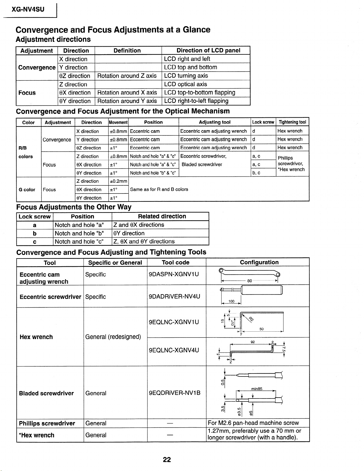
Convergence and Focus Adjustments at a Glance
Adjustment directions
Adjustment ( Direction (
IX direction 1
Convergence Y direction
Definition Direction of LCD panel
) LCD right and left
LCD top and bottom
8Z direction Rotation around Z axis LCD turning axis
Focus
1 Z direction
1
[8X direction I Rotation around X axis I LCD top-to-bottom flapping
1 LCD optical axis
I8Y direction ( Rotation around Y axis 1 LCD right-to-left flapping
Convergence and Focus Adjustment for the Optical Mechanism
Color
FUB
colors
Adjustment Direction Movement
X direction
Convergence Y direction
02 direction
Z direction
Focus
Focus
0X direction ~1 O
8Y direction *lo
k0.8mm Eccentric cam
k0.8mm Eccentric cam
4 O
=t0.8mm Notch and hole “a” & “c”
Position Adjusting tool
Eccentric cam adjusting wrench
Eccentric cam adjusting wrench
Eccentric cam
Notch and hole “a” & “c”
Notch and hole “b” & “c”
Same as for R and B colors
Eccentric cam adjusting wrench d
Eccentric screwdriver,
Bladed screwdriver
Focus Adjustments the Other Way
Lock screw
a
b
C
Position
Notch and hole “a” Z and 8X directions
Notch and hole “b”
Notch and hole “c”
0Y direction
Z, 8X and 8Y directions
Related direction
Lock screw Tightening tool
d
d
Hex wrench
Hex wrench
Hex wrench
Phillips
screwdriver,
*Hex wrench
Convergence and Focus Adjusting and Tightening Tools
Tool
Eccentric cam
Specific or General
Specific
adjusting wrench
Eccentric screwdriver Specific
Hex wrench
General (redesigned)
Bladed screwdriver General
Phillips screwdriver
General
*Hex wrench General
Tool code
9DASPN-XGNVI U
SDADRiVER-NV4U
SEQLNC-XGNVI U
9EQLNCXGNV4U
SEQDRiVER-NV1 B
Configuration
Izz=?
&
100
Iz+I
:zj
2
4
$ r=
?+I-+
92
t
-I
in
?
For M2.6 pan-head machine screw
1.27mm, preferably use a 70 mm or
longer screwdriver (with a handle).
XG-NV4SU
I
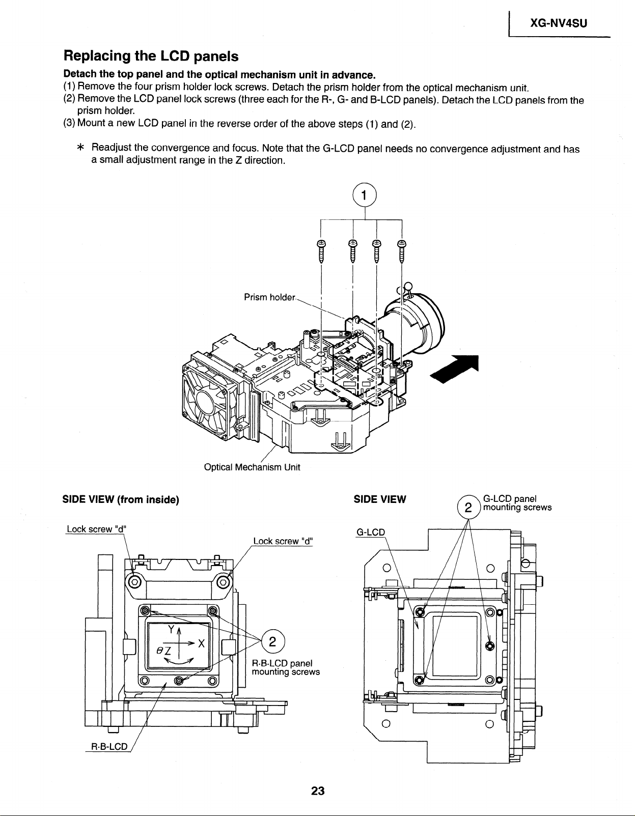
Replacing the LCD panels
Detach the top panel and the optical mechanism unit in advance.
(1) Remove the four prism holder lock screws. Detach the prism holder from the optical mechanism unit.
(2) Remove the LCD panel lock screws (three each for the R-, G- and B-LCD panels). Detach the LCD panels from the
prism holder.
(3) Mount a new LCD panel in the reverse order of the above steps (1) and (2).
4~ Readjust the convergence and focus. Note that the G-LCD panel needs no convergence adjustment and has
a small adjustment range in the Z direction.
1
0
SIDE VIEW (from inside)
Lock screw “d”
\
ReB-LCD /
Optical Mechanism Unit
Lock screw “d”
panel
screws
SIDE VIEW
G-LCD panel
mounting screws
2
0
XG-NV4SU 1
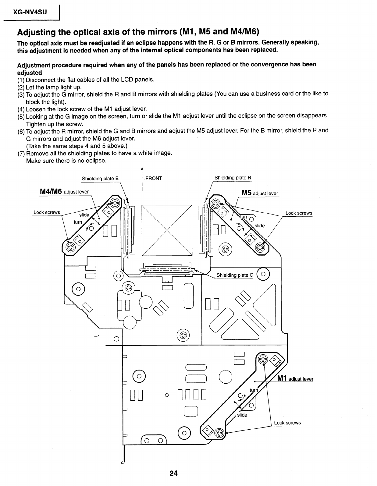
Adjusting the optical axis of the mirrors (Ml, M5 and M4/M6)
The optical axis must be readjusted if an eclipse happens with the R. G or B mirrors. Generally speaking,
this adjustment is needed when any of the internal optical components has been replaced.
Adjustment procedure required when any of the panels has been replaced or the convergence has been
adjusted
(1) Disconnect the flat cables of all the LCD panels.
(2) Let the lamp light up.
(3) To adjust the G mirror, shield the R and B mirrors with shielding plates (You can use a business card or the like to
block the light).
(4) Loosen the lock screw of the Ml adjust lever.
(5) Looking at the G image on the screen, turn or slide the Ml adjust lever until the eclipse on the screen disappears.
Tighten up the screw.
(6) To adjust the R mirror, shield the G and B mirrors and adjust the M5 adjust lever. For the B mirror, shield the R and
G mirrors and adjust the M6 adjust lever.
(Take the same steps 4 and 5 above.)
(7) Remove all the shielding plates to have a white image.
Make sure there is no eclipse.
M4/M6 adjust lever
Lock screws
Shielding plate B
\
‘I[
I
I I
I
I
I
I
I
I
I
I
I
I
I
I
I
I
J
c
FRONT
T
Shielding plate R
Shielding plate G
Lock
screws
24
XG-NV4SU
I
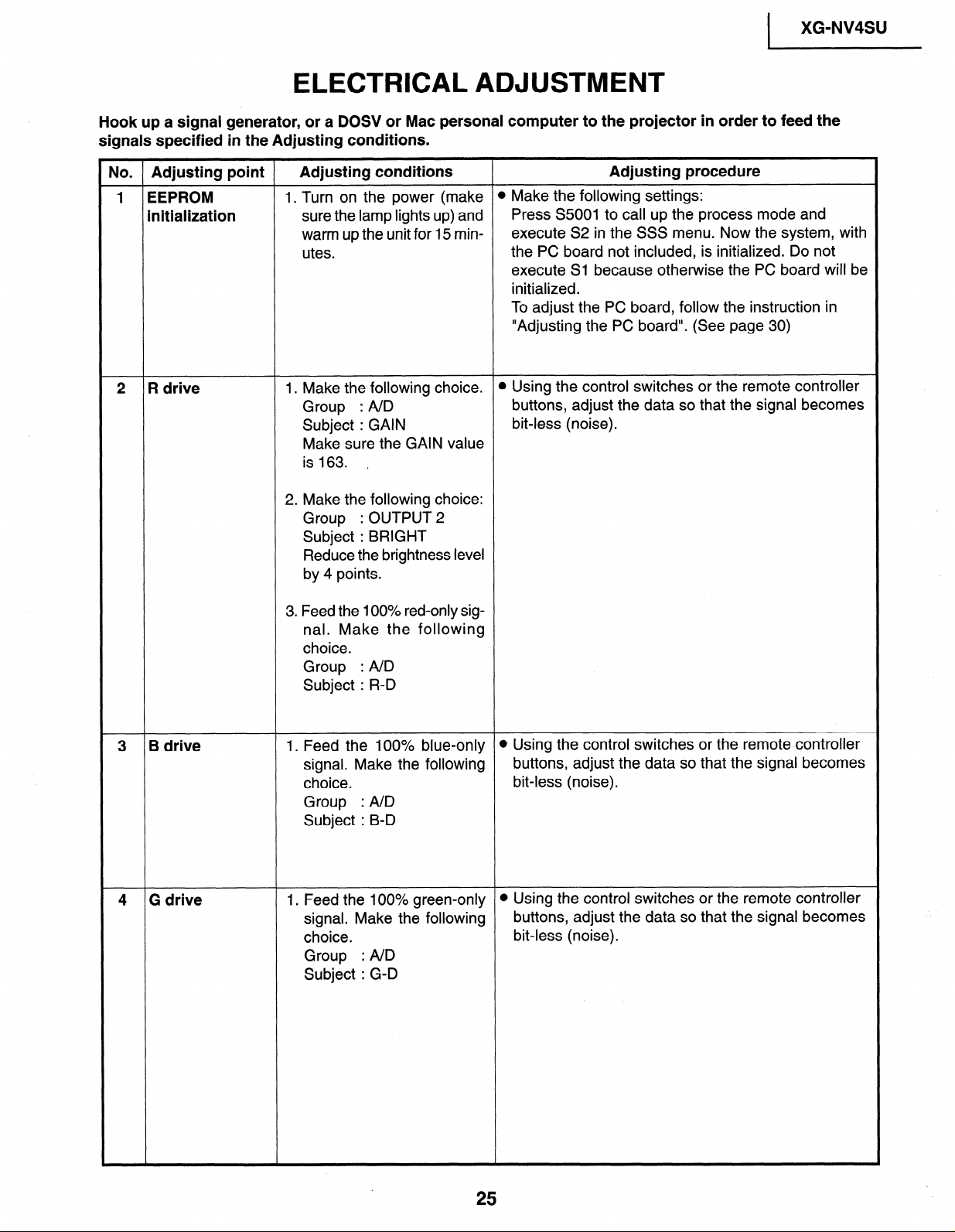
ELECTRICAL ADJUSTMENT
Hook up a signal generator, or a DOSV or Mac personal computer to the projector in order to feed the
signals specified in the Adjusting conditions.
No. Adjusting point
Adjusting conditions Adjusting procedure
1 EEPROM 1. Turn on the power (make
initialization sure the lamp lights up) and
warm up the unit for 15 minutes.
2 R drive
1. Make the following choice.
Group : AID
Subject : GAIN
Make sure the GAIN value
is 163. ,
2. Make the following choice:
Group : OUTPUT 2
Subject : BRIGHT
Reduce the brightness level
by 4 points.
3. Feed the 100% red-only signal. Make the following
choice.
Group : AID
Subject : R-D
l Make the following settings:
Press S5001 to call up the process mode and
execute S2 in the SSS menu. Now the system, with
the PC board not included, is initialized. Do not
execute Sl because otherwise the PC board will be
initialized.
To adjust the PC board, follow the instruction in
“Adjusting the PC board”. (See page 30)
l Using the control switches or the remote controller
buttons, adjust the data so that the signal becomes
bit-less (noise).
3 B drive 1. Feed the 100% blue-only
signal. Make the following
choice.
Group : A/D
Subject : B-D
4 G drive 1. Feed the 100% green-only
signal. Make the following
choice.
Group : AID
Subject : G-D
l Using the control switches or the remote controller
buttons, adjust the data so that the signal becomes
bit-less (noise).
l Using the control switches or the remote controller
buttons, adjust the data so that the signal becomes
bit-less (noise).
25
XG-NV4SU
I
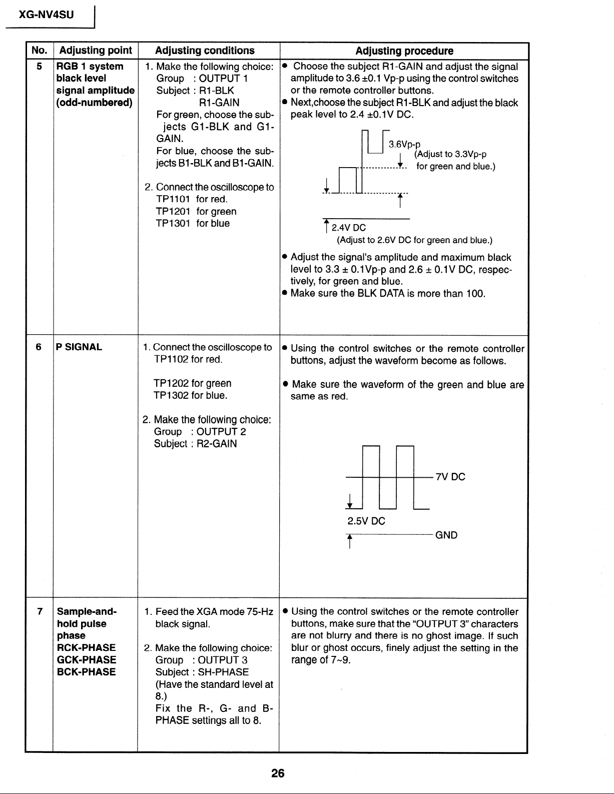
No. Adjusting point Adjusting conditions
5 RGB 1 system 1. Make the following choice:
black level Group : OUTPUT 1
signal amplitude Subject : Rl-BLK
(odd-numbered)
For green, choose the sub-
jects Gl-BLK and GlGAIN.
For blue, choose the sub-
jects Bl-BLK and Bl-GAIN.
2. Connect the oscilloscope to
TPllOl for red.
TP1201 for green
TP1301 for blue
Rl -GAIN
Adjusting procedure
l Choose the subject Rl-GAIN and adjust the signal
amplitude to 3.6 ~0.1 Vp-p using the control switches
or the remote controller buttons.
l Next,choose the subject Rl -BLK and adjust the black
peak level to 2.4 +O.lV DC.
3.6Vp-p
(Adjust to 3.3Vp-p
-____-_________
4
- - ~ --mm_ ____________ mm
1
for green and blue.)
f
2.4V DC
(Adjust to 2.6V DC for green and blue.)
l Adjust the signal’s amplitude and maximum black
level to 3.3 rt 0.1 Vp-p and 2.6 + 0.1 V DC, respectively, for green and blue.
l Make sure the BLK DATA is more than 100.
6 P SIGNAL
7 Sample-and-
hold pulse
phase
RCK-PHASE
GCK-PHASE
BCK-PHASE
1. Connect the oscilloscope to
TPl102 for red.
TP1202 for green
TP1302 for blue.
2. Make the following choice:
Group : OUTPUT 2
Subject : R2-GAIN
1. Feed the XGA mode 75Hz l Using the control switches or the remote controller
black signal.
2. Make the following choice:
Group : OUTPUT 3
Subject : SH-PHASE
(Have the standard level at
8)
Fix the R-, G- and BPHASE settings all to 8.
l Using the control switches or the remote controller
buttons, adjust the waveform become as follows.
l Make sure the waveform of the green and blue are
same as red.
7V DC
-
2.5V DC
tGND
buttons, make sure that the “OUTPUT 3” characters
are not blurry and there is no ghost image. If such
blur or ghost occurs, finely adjust the setting in the
range of 7-9.
/

XG-NV4SU
I
No. Adjusting point Adjusting conditions
8 RGB counter-
voltage (25%) stripe signal (S-
adjustment
9 RGB gradation 1. Feed the green-only
1. Feed the black-and-red l Using the control switches or the remote controller
VGA).
2. Make the following choice:
Group : OUTPUT 3
Subject : RC (R)
regeneration SMPTE pattern signal.
adjustment
Group : OUTPUT 1
Subject : Gl-BLK
Adjusting procedure
buttons, adjust the data in order to minimize the
flicker.
l Make the same adjustment for BC (B) and GC (G).
l See if the image is equally adjusted at the center
and both sides of the screen. If not, readjust the
setting to have the image equal at right and left.
l Adjust the G-GAIN data until the gradation of the
portion @ (95% and 100% white) shown below can
be slightly recognized. Make sure also that the
gradation of the portion @ (0% and 5% black) is
visible.
10 RGB white
balance
11 Horizontal
center
12 Video picture
adjustment
I. Feed the 32-step gray scale
signal (S-VGA).
Group : OUTPUT 1
Subject : RI-BLK (R)
Bl-BLK (B)
1. Feed the NTSC monoscope pattern signal.
2. Group
Subject : N358-DLY (4)
Make sure the settings are
as above.
3. Group : VIDEO 1
Subject : NTSC-H
1. Feed the split color bar signal.
Group : VIDEO 1
Subject : PICTURE
: VIDEO 2
N443-DLY (0)
PAL-DLY
SECAM-DLY (0)
(0)
l Choose the subjects RI-BLK and Bl-BLK and
adjust the black balance of the gradation.
@ Using the control switches or the remote controller
buttons, adjust the data to have the same overscan.
l Using the control switches or the remote controller
buttons, adjust the black-to-white (100%) level
difference’to 2.2 kO.02 Vp-p.
2. Connect the oscilloscope
between pin (2) of P801
and GND.
27
XG-NV4SU
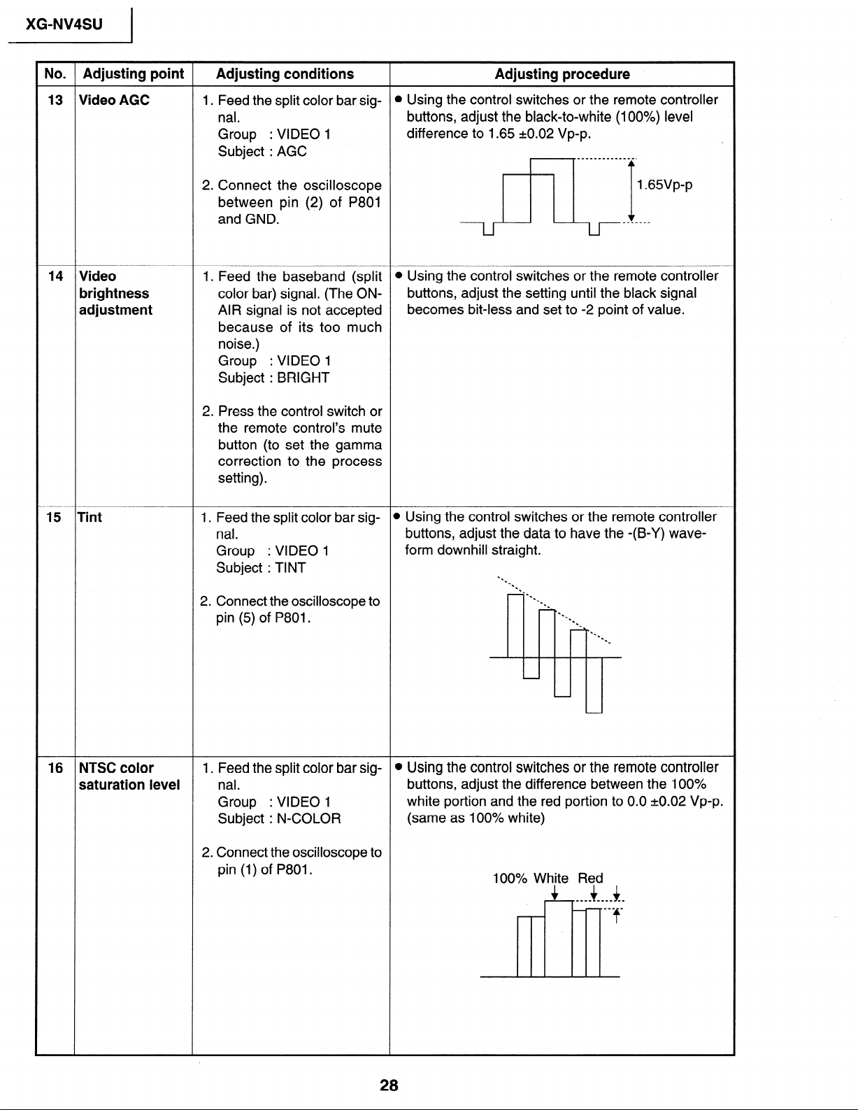
No. Adjusting point Adjusting conditions
13 Video AGC 1. Feed the split color bar sig-
nal.
Group
: VIDEO 1
Subject : AGC
2. Connect the oscilloscope
between pin (2) of P801
and GND.
14 Video
brightness
adjustment
1. Feed the baseband (split
color bar) signal. (The ONAIR signal is not accepted
because of its too much
noise.)
Group
: VIDEO 1
Subject : BRIGHT
2. Press the control switch or
the remote control’s mute
button (to set the gamma
correction to the process
setting).
Adjusting procedure
l Using the control switches or the remote controller
buttons, adjust the black-to-white (100%) level
difference to 1.65 20.02 Vp-p.
l Using the control switches or the remote controller
buttons, adjust the setting until the black signal
becomes bit-less and set to -2 point of value.
15 Tint 1. Feed the split color bar sig-
nal.
Group
: VIDEO 1
Subject : TINT
2. Connect the oscilloscope to
pin (5) of P801.
16 NTSC color
saturation level
1. Feed the split color bar signal.
Group
: VIDEO 1
Subject : N-COLOR
2. Connect the oscilloscope to
pin (1) of P801.
l Using the control switches or the remote controller
buttons, adjust the data to have the -(B-Y) wave-
form downhill straight.
l .
-.
-.
l c
-.
l .
-*.
=.
l .
-.
.
l .
l .
l .
-
l Using the control switches or the remote controller
buttons, adjust the difference between the 100%
white portion and the red portion to 0.0 +0.02 Vp-p.
(same as 100% white)
100% White Red
+ 4 ____ ____ __
___ _
f
28
3
XG-NV4SU
I
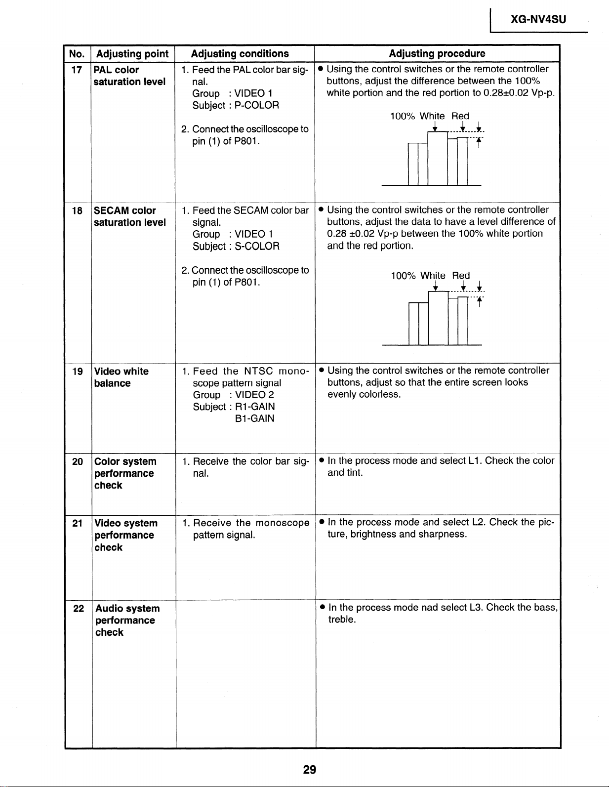
No. Adjusting point Adjusting conditions
17 PAL color
1. Feed the PAL color bar sig-
saturation level nal.
: VIDEO 1
: VIDEO 1
18 SECAM color
saturation level
Group
Subject : P-COLOR
2. Connect the oscilloscope to
pin (1) of P801.
1. Feed the SECAM color bar l Using the control switches or the remote controller
signal.
Group
Subject : S-COLOR
2. Connect the oscilloscope to
pin (1) of P801.
Adjusting procedure
l Using the control switches or the remote controller
buttons, adjust the difference between the 100%
white portion and the red portion to 0.28~0.02 Vp-p.
100% White Red
4 4 ___- __I_ --
mm_ _
f
c
buttons, adjust the data to have a level difference of
0.28 kO.02 Vp-p between the 100% white portion
and the red portion.
100% White Red
4 4 _-_- -___ _-
___ _
f
19 Video white 1. Feed the NTSC mono-
balance
20 Color system
performance
scope pattern signal
Group
Subject : Rl-GAIN
1. Receive the color bar signal.
: VIDEO 2
Bl -GAIN
check
21 Video system
performance
1. Receive the monoscope
pattern signal.
check
22 Audio system
performance
check
t
l Using the control switches or the remote controller
buttons, adjust so that the entire screen looks
evenly colorless.
l In the process mode and select Ll. Check the color
and tint.
l In the process mode and select L2. Check the pic-
ture, brightness and sharpness.
l In the process mode nad select L3. Check the bass,
treble.
XG-NV4SU
I
No. Adjusting point
Adjusting conditions
23 RGB 1. Receive the RGB signal.
performance
check
24 Off-timer
performance
check
25 Thermistor 1. Heat the thermistor using a
l In the process mode and select L4. Check the pic-
ture, brightness, red, blue, clock, phase, horizontal
position, and vertical position.
l In the process mode and select OFF. Make sure that
the off-timer starts with “5” (minutes), counts down
each minute in 1 second, and turns off the set at “0".
l Make sure the “TEMP” is displayed.
Adjusting procedure
performance dryer.
check
26 Factory settings
27 Automatic 1. Receive the PHASE check
0 Make the following settings.
~1
l Call the VGA/S-VGA/XGA mode and make sure
synchronization pattern signal. that the clock, phase, horizontal and vertical posi-
i
tions can be automatically adjusted.
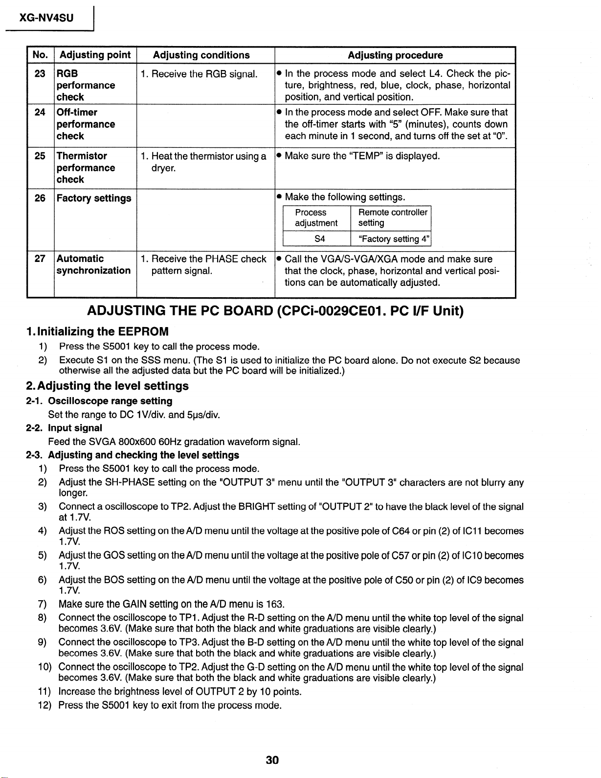
ADJUSTING THE PC BOARD (CPCi-0029CE01. PC l/F Unit)
1. Initializing the EEPROM
1) Press the S5001 key to call the process mode.
2) Execute Sl on the SSS menu. (The Sl is used to initialize the PC board alone. Do not execute S2 because
othetwise all the adjusted data but the PC board will be initialized.)
2. Adjusting the level settings
2-l. Oscilloscope range setting
Set the range to DC lV/div. and 5us/div.
2-2. Input signal
Feed the SVGA 800x600 60Hz gradation waveform signal.
2-3. Adjusting and checking the level settings
Press the S5001 key to call the process mode.
1)
Adjust the SH-PHASE setting on the “OUTPUT 3” menu until the “OUTPUT 3” characters are not blurry any
2)
longer.
Connect a oscilloscope to TP2. Adjust the BRIGHT setting of “OUTPUT 2” to have the black level of the signal
3)
at I .7V.
Adjust the ROS setting on the A/D menu until the voltage at the positive pole of C64 or pin (2) of ICll becomes
4)
1.7v.
5) Adjust the GOS setting on the A/D menu until the voltage at the positive pole of C57 or pin (2) of ICI 0 becomes
1.7v.
Adjust the BOS setting on the A/D menu until the voltage at the positive pole of C50 or pin (2) of IC9 becomes
6)
1.7v.
Make sure the GAIN setting on the A/D menu is 163.
7)
8) Connect the oscilloscope to TPl . Adjust the R-D setting on the A/D menu until the white top level of the signal
becomes 3.6V. (Make sure that both the black and white graduations are visible clearly.)
Connect the oscilloscope to TP3. Adjust the B-D setting on the A/D menu until the white top leve
9)
becomes 3.6V. (Make sure that both the black and white graduations are visible clearly.)
Connect the oscilloscope to TP2. Adjust the G-D setting on the A/D menu until the white top leve
10)
becomes 3.6V. (Make sure that both the black and white graduations are visible clearly.)
11) Increase the brightness level of OUTPUT 2 by 10 points.
Press the S5001 key to exit from the process mode.
12)
of the signal
of the signal
 Loading...