


English
Deutsch
AN-C12MZ
Français
Español
Wide-zoom lens for LCD projector
Weitwinkel-zoomobjektiv für LCD-Projektor
Objectif grand angle-zoom pour projecteur LCD
Objetivo granangular-zoom para proyector LCD
INSTALLATION MANUAL
INSTALLATIONSHANDBUCH
MANUEL D’INSTALLATION
MANUAL DE INSTALACIÓN
Changing the Lens
When changing the lens, use the supplied lens cover stick.
 Info
Info
•Before changing the lens turn off the power to the projector and remove the power cord from the wall outlet.
•Do not attempt to change the lens while the projector is mounted on the ceiling.
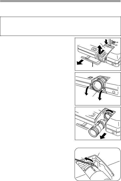
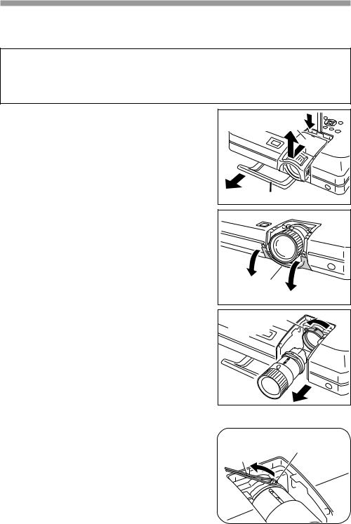
1 Pull out the carrying handle.
2 Use the tip of the supplied lens cover stick to push down on the groove on top of the upper half of lens cover while pulling forward to remove it with your hand.
3 To remove the bottom half of the lens cover, pull it down and towards you.
Upper half of the |
lens cover |
2 |
1 |
Carrying handle |
Lower half of |
3 |
the lens cover |
|
4
5
To remove the lens, hold it in one hand, to keep it from dropping, while you turn the lens fastener catch tab in the direction of the arrows in the illustration with your other hand.
•If the lens fastener ring is stiff, attach the supplied lock release strap to the catch tab on the lens fastener ring and pull the strap to turn it.
Remove the lens.
Lens fastener |
4 |
catch tab |
|
|
5 |
Procedure for loosening the stiff lens fastener ring
Lock release |
Lens fastener |
|
strap |
||
catch tab |
||
|
 -1
-1
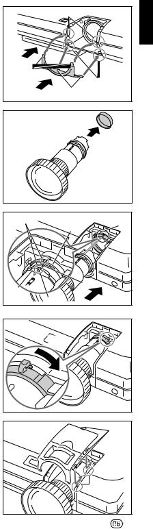
6 First insert tabs a of the lens cover into tab holes Aof the projector, then push tabs binto tab holes Buntil it clicks into place.
7 Push in the carrying handle.
8 Remove the cap from the end of the lens that you will attach to the projector.
9 Make sure that the two grooves on the lens fastener ring are facing upward.
10 Ensure that the two grooves on the lens mount face upward and the pin of lens insertion area is inserted into the hole of the lens mount as you push the lens into the projector.
•Make sure the lens is pushed into the projector interior firmly.
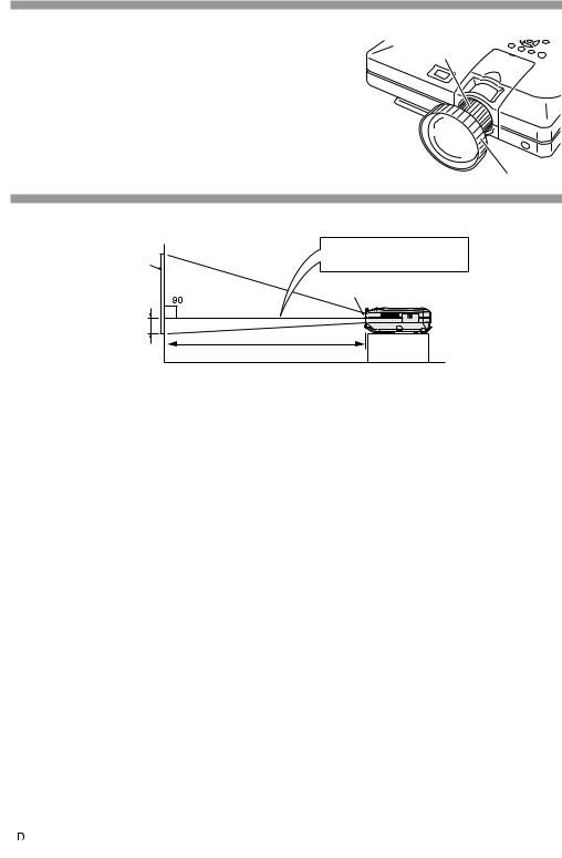
11 Turn the lens fastener catch tab in the direction of the arrows in the illustration until it stops.
•Be careful not to turn the lens fastener ring too tight, as the lens fastener ring will be stiff the next time the lens is changed.
12 After inserting the upper half of the lens cover tabs into the projector tab holes, slide the lens cover towards the projector until it clicks into place.
•If the upper half of the lens cover is not secured to the projector, you will not be able to turn the power on.
Tab holes B |
7 |
Tabs b |
Tab holes A |
6 Tabs a |
8
Grooves |
Lens fastener |
||
|
ring |
9 |
|
Lens |
|
Pin |
|
Hole |
10 |
||
mount |
|||
11 |
12 |
Tabs |
|
|
|
Tab holes |
|
-2 |
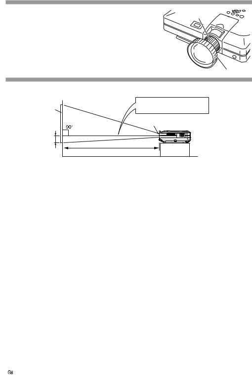
Adjust the picture size and focus
Zoom ring
Turn the zoom ring to adjust picture size.
Turn the focus ring to adjust the focus.
Focus ring
Picture size and projection ditance chart
|
Base line: |
Screen |
Horizontal line passing through |
the lens center |
|
|
Lens center |
H |
|
|
L : Projection distance |
NORMAL Mode (4:3)
Picture (Screen) size |
|
|
Projection distance (L) |
Distance from the lens center |
||||||||
Diag. (X) |
Width |
Height |
Maximum (L1) |
Minimum (L2) |
to the bottom of the image (H) |
|||||||
300" (762 cm) |
240" (609.6 cm) |
180" (457.2 cm) |
30' |
5" |
(9.26 m) |
24' |
3" |
(7.38 m) |
17 |
3 / 4" |
(45.1 cm) |
|
250" (635 cm) |
200" (508 cm) |
150" (381 cm) |
25' |
4" |
(7.71 m) |
20' |
2" |
(6.14 m) |
14 |
13 / 16" (37.6 cm) |
||
200" (508 cm) |
160" (406.4 cm) |
120" (304.8 cm) |
20' |
3" |
(6.15 m) |
16' |
1" |
(4.89 m) |
11 |
13 / 16" (30.0 cm) |
||
150" (381 cm) |
120" (304.8 cm) |
90" (228.6 cm) |
15' |
2" |
(4.60 m) |
12' |
|
(3.65 m) |
8 |
7 |
/ 8" |
(22.5 cm) |
100" (254 cm) |
80" (203.2 cm) |
60" (152.4 cm) |
10' |
|
(3.04 m) |
7' 11" |
(2.41 m) |
5 |
7 |
/ 8" |
(15.0 cm) |
|
84" (213.3 cm) |
67" (170.1 cm) |
50" (127 cm) |
8' |
4" |
(2.54 m) |
6' |
8" |
(2.02 m) |
4 |
15 / 16" (12.6 cm) |
||
72" (182.8 cm) |
58" (147.3 cm) |
43" (109.2 cm) |
7' |
2" |
(2.17 m) |
5' |
8" |
(1.72 m) |
4 |
1 |
/ 4" |
(10.8 cm) |
60" (152.4 cm) |
48" (121.9 cm) |
36" (91.4 cm) |
5'11" |
(1.80 m) |
4' |
8" |
(1.42 m) |
3 |
9 |
/ 16" |
(9.0 cm) |
|
40" (101.6 cm) |
32" (81.2 cm) |
24" (60.9 cm) |
3'11" |
(1.18 m) |
3' |
1" |
(0.92 m) |
2 |
3 |
/ 8" |
(6.0 cm) |
|
|
|
|
|
|
|
|
|
|
|
|
|
|
The formula for picture size and projection distance
L1 (ft) = (0.0311X – 0.0676) / 0.3048
L2 (ft) = (0.0248X – 0.0693) / 0.3048 H (in) = (0.1504X – 0.0328) / 2.54
X: Picture size (diag.) (in) L: Projection distance (ft)
L1: Maximum projection distance (ft) L2: Minimum projection distance (ft)
H:Distance from the lens center to the bottom of the image (in)
STRETCH Mode (16:9)
Picture (Screen) size |
|
|
Projection distance (L) |
Distance from the lens center |
||||||||
Diag. (X) |
Width |
Height |
Maximum (L1) |
Minimum (L2) |
to the bottom of the image (H) |
|||||||
300" (762 cm) |
261" (662.9 cm) |
147" (373.4 cm) |
33' |
2" |
(10.10 m) |
26' |
5" |
(8.04 m) |
–5" |
|
|
(–12.7 cm) |
250" (635 cm) |
218" (553.7 cm) |
123" (312.4 cm) |
27' |
7" |
(8.40 m) |
22' |
|
(6.69 m) |
–4 |
3 |
/ 16"(–10.6 cm) |
|
225" (571.5 cm) |
196" (497.8 cm) |
110" (279.4 cm) |
24'10" |
(7.55 m) |
19' |
9" |
(6.01 m) |
–3 |
3 |
/ 4" |
(–9.5 cm) |
|
200" (508 cm) |
174" (441.9 cm) |
98" (248.9 cm) |
22' |
1" |
(6.71 m) |
17' |
7" |
(5.34 m) |
–3 |
3 |
/ 8" |
(–8.5 cm) |
150" (381 cm) |
131" (332.7 cm) |
74" (188 cm) |
16' |
6" |
(5.01 m) |
13' |
2" |
(3.99 m) |
–2 |
1 |
/ 2" |
(–6.4 cm) |
133" (337.8 cm) |
116" (294.6 cm) |
65" (165.1 cm) |
14' |
7" |
(4.44 m) |
11' |
7" |
(3.53 m) |
–2 |
3 |
/ 16"(–5.6 cm) |
|
106" (269.2 cm) |
92" (233.6 cm) |
52" (132 cm) |
11' |
7" |
(3.52 m) |
9' |
3" |
(2.80 m) |
–1 |
3 |
/ 4" |
(–4.5 cm) |
100" (254 cm) |
87" (220.9 cm) |
49" (124.4 cm) |
10'11" |
(3.32 m) |
8' |
8" |
(2.63 m) |
–1 |
5 |
/ 8" |
(–4.2 cm) |
|
92" (233.6 cm) |
80" (203.2 cm) |
45" (114.3 cm) |
10' |
1" |
(3.05 m) |
8' |
|
(2.42 m) |
–1 |
9 |
/ 16"(–3.9 cm) |
|
84" (213.3 cm) |
73" (185.4 cm) |
41" (104.1 cm) |
9' |
2" |
(2.78 m) |
7' |
3" |
(2.20 m) |
–1 |
7 |
/ 16"(–3.6 cm) |
|
72" (182.8 cm) |
63" (160 cm) |
35" (88.9 cm) |
7'10" |
(2.37 m) |
6' |
3" |
(1.88 m) |
–1 |
3 |
/ 16"(–3.0 cm) |
||
60" (152.4 cm) |
52" (132 cm) |
29" (73.6 cm) |
6' |
6" |
(1.97 m) |
5' |
2" |
(1.55 m) |
|
–31 / 32"(–2.5 cm) |
||
40" (101.6 cm) |
35" (88.9 cm) |
20" (50.8 cm) |
4' |
3" |
(1.29 m) |
3' |
4" |
(1.01 m) |
|
–11 / 16"(–1.7 cm) |
||
The formula for picture size and projection distance
L1 (ft) = (0.0339X – 0.0669) / 0.3048
L2 (ft) = (0.027X – 0.0683) / 0.3048 H (in) = (– 0.0424X + 0.0079) / 2.54
 Note
Note
•There is error of ±3% in the formula above.
•Values with a minus(–) sign indicate the distance of the lens center below the bottom of screen.
 -3
-3
Handling Precautions
●Do not disassemble this lens.
Please refer to your authorized dealer for any maintenance and inspections requiring an open cabinet.
●Except for the lens fastener ring, touching any other internal part could cause personal injury or machine malfunction.
●Do not touch any glass or protruding part of the lens. This may cause personal injury and reduced performance of the projector.
●When maintaining the projector the following points should be noted.
•When cleaning the lens be sure to use a commercial air blower or lens cleaning paper (used in cleaning glasses and cameras).
•The surface of the lens is very delicate. Do not allow hard objects to bump or rub against it.
Supplied Accessories
• |
1 lens cover stick |
• 1 lock release strap |
• |
Installation Manual (this manual) |
|
|
|
|
|
|
|
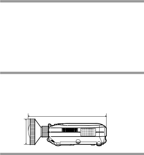
Projector and Lens Dimensions
Unité : mm (pouces)
377.3 - 379.3 (147/8" - 1415/16") |
ø107 |
Specifications
Product type |
Wide-zoom lens for LCD projector |
|
|
Model |
AN-C12MZ |
|
|
Type of lens |
Zoom lens |
|
|
Picture size (diagonal) |
30'' to 300'' |
|
|
Focal length |
24.5 to 30.7 mm (15/16'' to 13/16'') |
F no. |
2.2 to 2.7 |
|
|
Throw ratio |
1:1.18 to 1.48 |
|
|
Weight |
1,520g (3.35 lbs) |
|
|
Dimensions |
ø107 × 202 mm (715/16'') |
 -4
-4
Objektiv austauschen
Verwenden Sie für den Austausch des Objektivs den beiliegenden Objektivabdeckungsstab.
 Info
Info
•Schalten Sie die Stromversorgung zum Projektor aus und ziehen Sie das Netzkabel aus der Netzsteckdose heraus, bevor das Objektiv abgenommen wird.
•Versuchen Sie nicht, das Objektiv abzunehmen, während der Projektor noch an der Decke installiert ist.
1 Ziehen Sie den Tragegriff heraus.
2 Drücken Sie mit der Spitze des beiliegenden Objektivabdeckungsstabs auf die Nut der oberen Hälfte der Objektivabdeckung, während sie nach unten gedrückt wird, um sie mit der Hand abzunehmen.
3 Drücken Sie die untere Hälfte der Objektivabdeckung nach unten und dann zu sich hin, um diese abzunehmen.
4 Halten Sie das Objektiv zum Abnehmen mit einer Hand fest, damit es nicht herunterfällt,und drehen Sie den Objektivverbindungs-Sperrzunge gleichzeitig mit der anderen Hand in Pfeilrichtung, siehe Abbildung.
•Wenn der Objektivverbindungsring schwer drehbar ist, befestigen Sie den Löseriemen an der Sperrzunge auf dem Objektivverbindungsring und ziehen Sie am Riemen, um ihn zu drehen.
5 Nehmen Sie das Objektiv ab.
Obere Hälfte der
Objektivabdeckung
|
2 |
1 |
|
Tragegriff |
|
Untere Hälfte der |
3 |
Objektivabdeckung |
|
Objektivverbindungs- |
4 |
Sperrzunge |
|
|
5 |
Verfahren zum Lösen eines schwer drehbaren Objektivverbindungsrings
Objektivverbindungs-
Sperrzunge
Löseriemen
 1
1

6 Setzen Sie zuerst die Sperrzungen a der Objektivabdeckung in die Zungenöffnungen Ades Projektors ein, drücken Sie dann die Sperrzungenbin die ZungenöffnungenB, bis diese einrasten.
7 Schieben Sie den Tragegriff ein.
8 Entfernen Sie die Kappe von dem Objektivende, das Sie am Projektor befestigen.
9 Vergewissern Sie sich, dass die zwei Nuten im objektivverbindungsring nach oben weisen.
10 Stellen Sie sicher, das die zwei Nuten an der Objektivhalterung nach oben weisen und der Stift des Objektiveinsatzbereichs in die Öffnung der Objektivhalterung einrastet, sobald Sie das Objektiv in den Projektor einschieben.
•Vergewissern Sie sich, dass das Objektiv fest im Innern des Projektors eingesetzt ist.
11 Drehen Sie den ObjektivverbindungsSperrzunge bis zum Anschlag in Pfeilrichtung, siehe Abbildung.
•Dabei aufpassen, dass der Objektivverbindungsring nicht zu fest aufgedreht wird, da der Objektivverbindungsring beim nächsten Abnehmen schwer drehbar sein wird.
12 Schieben Sie, nachdem die obere Hälfte der Objektivabdeckung in die ProjektorSperrzungenöffnungen eingesetzt worden ist, die Objektivabdeckung zum Projektor hin, bis diese einrastet.
•Wenn die obere Hälfte der Objektivabdeckung nicht fest am Projektor befestigt ist, können Sie den Projektor nicht einschalten.
Sperrzungenöffnungen B |
7 |
Sperrzungen b |
Sperrzungenöffnungen A |
6 Sperrzungen a |
8
Nuten |
Objektivverbindungsring |
|
|
9 |
|
|
|
|
|
|
Stift |
|
Öffnung |
10 |
Objektivhalterung |
|
|
11 |
12 |
Sperrzungen |
Sperrzungenöffnungen |
2 |
Einstellen von Bildformat und Fokus
Zoomring
Drehen Sie den Zoomring, um das Bildformat einzustellen.
Drehen Sie den Fokusring, um den Fokus einzustellen.
Fokusring
Tabelle für Bildformat und Projektionsentfernung
|
Grundlinie: |
Bildwand |
Horizontale Linie, die die |
Objektivmitte passiert. |
|
|
Objektivmitte |
H |
|
|
L: Projektionsabstand |
NORMAL Modus (4:3)
Bildgröße (Bildwandgröße) |
|
|
Projektionsabstand (L) |
Abstand von der Objektivmitte |
||||||||
Diag. (X) |
Breite |
Höhe |
Maximum (L1) |
Minimum (L2) |
zur Bildunterkante (H) |
|||||||
300" (762 cm) |
240" (609,6 cm) |
180" (457,2 cm) |
30' |
5" |
(9,26 m) |
24' |
3" |
(7,38 m) |
17 |
3 / 4" |
(45,1 cm) |
|
250" (635 cm) |
200" (508 cm) |
150" (381 cm) |
25' |
4" |
(7,71 m) |
20' |
2" |
(6,14 m) |
14 |
13 / 16" (37,6 cm) |
||
200" (508 cm) |
160" (406,4 cm) |
120" (304,8 cm) |
20' |
3" |
(6,15 m) |
16' |
1" |
(4,89 m) |
11 |
13 / 16" (30,0 cm) |
||
150" (381 cm) |
120" (304,8 cm) |
90" (228,6 cm) |
15' |
2" |
(4,60 m) |
12' |
|
(3,65 m) |
8 |
7 |
/ 8" |
(22,5 cm) |
100" (254 cm) |
80" (203,2 cm) |
60" (152,4 cm) |
10' |
|
(3,04 m) |
7' 11" |
(2,41 m) |
5 |
7 |
/ 8" |
(15,0 cm) |
|
84" (213,3 cm) |
67" (170,1 cm) |
50" (127 cm) |
8' |
4" |
(2,54 m) |
6' |
8" |
(2,02 m) |
4 |
15 / 16" (12,6 cm) |
||
72" (182,8 cm) |
58" (147,3 cm) |
43" (109,2 cm) |
7' |
2" |
(2,17 m) |
5' |
8" |
(1,72 m) |
4 |
1 |
/ 4" |
(10,8 cm) |
60" (152,4 cm) |
48" (121,9 cm) |
36" (91,4 cm) |
5'11" |
(1,80 m) |
4' |
8" |
(1,42 m) |
3 |
9 |
/ 16" |
(9,0 cm) |
|
40" (101,6 cm) |
32" (81,2 cm) |
24" (60,9 cm) |
3'11" |
(1,18 m) |
3' |
1" |
(0,92 m) |
2 |
3 |
/ 8" |
(6,0 cm) |
|
|
|
|
|
|
|
|
|
|
|
|
|
|
Die Formel für die Bildgröße und den Projektionsabstand
L1 (Fuß) = (0,0311X – 0,0676) / 0,3048 L2 (Fuß) = (0,0248X – 0,0693) / 0,3048 H (Zoll) = (0,1504X – 0,0328) / 2,54
X : Bildgröße (diag.) (Zoll)
L : Projektionsabstand (Fuß)
L1 : Maximaler Projektionsabstand (Fuß)
L2 : Minimaler Projektionsabstand (Fuß)
H: Abstand von der Objektivmitte zur unteren Bildkante (Zoll)
STRETCH Modus (16:9)
Bildgröße (Bildwandgröße) |
|
|
Projektionsabstand (L) |
Abstand von der Objektivmitte |
||||||||
Diag. (X) |
Breite |
Höhe |
Maximum (L1) |
Minimum (L2) |
zur Bildunterkante (H) |
|||||||
300" (762 cm) |
261" (662,9 cm) |
147" (373,4 cm) |
33' |
2" |
(10,10 m) |
26' |
5" |
(8,04 m) |
–5" |
|
|
(–12,7 cm) |
250" (635 cm) |
218" (553,7 cm) |
123" (312,4 cm) |
27' |
7" |
(8,40 m) |
22' |
|
(6,69 m) |
–4 |
3 |
/ 16"(–10,6 cm) |
|
225" (571,5 cm) |
196" (497,8 cm) |
110" (279,4 cm) |
24'10" |
(7,55 m) |
19' |
9" |
(6,01 m) |
–3 |
3 |
/ 4" |
(–9,5 cm) |
|
200" (508 cm) |
174" (441,9 cm) |
98" (248,9 cm) |
22' |
1" |
(6,71 m) |
17' |
7" |
(5,34 m) |
–3 |
3 |
/ 8" |
(–8,5 cm) |
150" (381 cm) |
131" (332,7 cm) |
74" (188 cm) |
16' |
6" |
(5,01 m) |
13' |
2" |
(3,99 m) |
–2 |
1 |
/ 2" |
(–6,4 cm) |
133" (337,8 cm) |
116" (294,6 cm) |
65" (165,1 cm) |
14' |
7" |
(4,44 m) |
11' |
7" |
(3,53 m) |
–2 |
3 |
/ 16"(–5,6 cm) |
|
106" (269,2 cm) |
92" (233,6 cm) |
52" (132 cm) |
11' |
7" |
(3,52 m) |
9' |
3" |
(2,80 m) |
–1 |
3 |
/ 4" |
(–4,5 cm) |
100" (254 cm) |
87" (220,9 cm) |
49" (124,4 cm) |
10'11" |
(3,32 m) |
8' |
8" |
(2,63 m) |
–1 |
5 |
/ 8" |
(–4,2 cm) |
|
92" (233,6 cm) |
80" (203,2 cm) |
45" (114,3 cm) |
10' |
1" |
(3,05 m) |
8' |
|
(2,42 m) |
–1 |
9 |
/ 16"(–3,9 cm) |
|
84" (213,3 cm) |
73" (185,4 cm) |
41" (104,1 cm) |
9' |
2" |
(2,78 m) |
7' |
3" |
(2,20 m) |
–1 |
7 |
/ 16"(–3,6 cm) |
|
72" (182,8 cm) |
63" (160 cm) |
35" (88,9 cm) |
7'10" |
(2,37 m) |
6' |
3" |
(1,88 m) |
–1 |
3 |
/ 16"(–3,0 cm) |
||
60" (152,4 cm) |
52" (132 cm) |
29" (73,6 cm) |
6' |
6" |
(1,97 m) |
5' |
2" |
(1,55 m) |
|
–31 / 32"(–2,5 cm) |
||
40" (101,6 cm) |
35" (88,9 cm) |
20" (50,8 cm) |
4' |
3" |
(1,29 m) |
3' |
4" |
(1,01 m) |
|
–11 / 16"(–1,7 cm) |
||
Die Formel für die Bildgröße und den Projektionsabstand
L1 (Fuß) = (0,0339X – 0,0669) / 0,3048 L2 (Fuß) = (0,027X – 0,0683) / 0,3048 H (Zoll) = (– 0,0424X + 0,0079) / 2,54
 Hinweis
•In der oben stehenden Formel ist eine Fehlerrate von ± 3% vorhanden.
•Werte mit einem Minuszeichen (–) zeigen den Abstand der Objektivmitte unterhalb der unteren Bildwandkante an.
 3
3
 Loading...