

Page 1
XG-C40XU/XE
SERVICE MANUAL
SERVICE-ANLEITUNG
S01B4XG-C40XU
LCD PROJECTOR
LCD PROJEKTOR
MODELS
MODELLE
In the interests of user-safety (Required by safety regulations in some countries) the set should be restored
to its original condition and only parts identical to those specified should be used.
Im lnteresse der Benutzersicherheit (erforderliche Sicherheitsregeln in einigen Ländern) muß das Gerät in seinen
Originalzustand gebracht werden. Außerdem dürfen für die spezifizierten Bauteile nur identische T eile verwendet
werden.
XG-C40XU/XE
CONTENTS INHAL T
Page
» SPECIFICATIONS...................................................... 2
» INPORTANT SERVICE SAFTY NOTES(for USA)...... 3
» OPERATION MANUAL ............................................... 7
» REMOVING OF MAJOR P ARTS.............................. 13
» RESETTING THE TOTAL LAMP TIMER.................. 18
» THE OPTICAL UNIT OUTLINE ................................ 19
» CONVERGENCE AND FOCUS ADJUSTMENT ........ 20
» ELECTRICAL ADJUSTMENT................................... 25
» ADJUSTING THE PC BOARD ................................. 31
» TROUBLE SHOOTING TABLE ................................ 32
» CHASSIS LAYOUT ................................................... 92
» BLOCK DIAGRAM .................................................... 94
» OVERALL WIRING DIAGRAM .................................. 96
» DESCRIPTION OF SCHEMATIC DIAGRAM............. 98
» WAVEFORMS........................................................... 99
» SCHEMATIC DIAGRAM......................................... 100
» PRINTED WIRING BOARD ASSEMBLIES ............ 148
» PARTS LIST
Ë
ELECTRICAL PARTS ........................................ 158
Ë
CABINET AND MECHANICAL PARTS .............. 178
Ë
ACCESSORIES PARTS .................................... 184
Ë
PACKING PARTS............................................... 184
» PACKING OF THE SET.......................................... 185
» TECHNISCHE DATEN ............................................. 48
» HINWEISE FÜR DAS WARTUNGSPERSONAL...... 49
» BEDIENUNGSANLEITUNG ..................................... 50
» ENTFERNEN DER HAUPTTEILE............................ 56
» NULLSTELLUNG DES LAMPEN-
BETRIEBSSTUNDENZÄHLERS (GESAMTZEIT).... 61
» ÜBERSICHT DER OPTIKEINHEIT .......................... 62
» EINSTELLUNG VON KONVERGENZ UND
BRENNPUNKT ......................................................... 63
» ELEKTRISCHE EINSTELLUNG............................... 68
» EINSTELLUNG DER PC-PLATINE .......................... 74
» FEHLERSUCHTABELLE.......................................... 75
» CHASSIS-ANORDNUNG ......................................... 92
» BLOCKSCHALTBILD................................................ 94
» GESAMTSCHALTPLAN ........................................... 96
» BESCHREIBUNG DES SCHEMATISCHEN
SCHALTPLANS ........................................................ 98
» WELLENFORMEN ................................................... 99
» SCHEMATISCHER SCHALTPLAN ........................ 100
» LEITERPLATTENEINHEITEN ................................ 148
» ERSATZTEILLISTE
Ë
ELEKTRISCHE BAUTEILE................................ 158
Ë
GEHÄUSE UND MECHANISCHE BAUTEILE... 178
Ë
ZUBEHÖRTEILE................................................ 184
Ë
VERPACKUNGSTEILE...................................... 184
» VERPACKEN DES GERÄTS.................................. 185
Seite
SHARP CORPORATION
1
Page 2

XG-C40XU/XE
Specifications
Product type
Video system
Display method
LCD panel
LCD Projector
Model
XG-C40XU/XE
PAL/SECAM/NTSC 3.58/NTSC 4.43/DTV 480P/DTV 720P/DTV 1080I
LCD panel × 3, RGB optical shutter method
Panel size: 22.9 mm (0.9") (13.9 [H] × 18.5 [W] mm)
Display method: Translucent TN liquid crystal panel
Drive method: TFT (Thin Film Transistor) Active Matrix panel
No. of dots: 786,432 dots (1,024 [H] × 768 [V])
Lens
Projection lamp
Contrast ratio
Video input signal
1–1.3 × zoom lens, F1.7–2.0, f = 33–43 mm
DC 200 W lamp
250:1
RCA Connector: VIDEO, composite video, 1.0 Vp-p, sync negative, 75 Ω terminated
RCA Connector: AUDIO, 0.5 Vrms more than 22 kΩ (stereo)
S-video input signal
4-pin Mini DIN connector
Y (luminance signal): 1.0 Vp-p, sync negative, 75 Ω terminated
C (chrominance signal): Burst 0.286 Vp-p, 75 Ω terminated
Horizontal resolution
Audio output
Computer RGB input signal
560 TV lines (video input), 750 TV lines (DTV 720P input, Dot by Dot)
3 W (monaural)
PIN MINI
D-
15-
SUB CONNECTOR
RGB separate/composite sync/sync on green type analog input: 0–0.7 Vp-p, positive,
75 Ω terminated
Pixel clock
Vertical frequency
Horizontal frequency
Computer control signal
Speaker system
Rated voltage
Input current
Rated frequency
Power consumption
Operating temperature
Storage temperature
Cabinet
I/R carrier frequency
Laser pointer of remote control
Dimensions (approx.)
TEREO MINIJACK
S
ORIZONTAL SYNC. SIGNAL
H
ERTICAL SYNC. SIGNAL
V
12–230 MHz
43–200 Hz
15–126 kHz
9-pin Mini DIN female connector (RS-232C Input Port)
8 cm (3
AC 100–240 V
3.3 A
50/60 Hz
300 W
41°F to + 104°F (+ 5°C to + 40°C)
-4°F to + 140°F (– 20°C to + 60°C)
Plastic
38 kHz
Wave length: 650 nm / Max. output: 1 mW / Class II Laser Product
1
/64" (W) × 4 49/64" (H) × 12 13/64" (D) (229 × 121 × 310 mm) (main body only)
9
19
/32" (W) × 5 9/32" (H) × 14 7/64" (D) (243.5 × 134 × 358.4 mm) (including adjustment feet
9
: AUDIO, 0.5 Vrms, more than 22 kΩ (stereo)
: TTL level (positive/negative) or composite sync (Apple only)
: Same as above
3
⁄32") round
and projecting parts)
Weight (approx.)
Supplied accessories
10.6 lbs. (4.8 kg)
Remote control, Two AA size batteries, Power cord (11' 10" 3.6m), Computer RGB cable
(9' 10" 3 m), Computer audio cable (9' 10" 3 m), USB mouse control cable (3' 3" 1 m),
DIN-D-sub RS-232C cable (6
(attached), CD-ROM, LCD projector operation manual, LCD projector quick references,
Sharp Advanced Presentation Software operation manual
Replacement parts
Lamp unit (Lamp/cage module) (BQC-XGC40XU/1), Remote control (RRMCG1579CESA),
(RRMCG1584CESA),AA size batteries, Power cord (QACCU5013CEZZ(XG-C40XU),
QACCB5024CENA(XG-C40XE),QACCV4002CEZZ(XG-C40XE)), Computer RGB cable
(QCNWG0002CEZZ), Computer audio cable (QCNW-4870CEZZ), USB mouse control
cable (QCNWG0007CEPZ), DIN-D-sub RS-232C cable (QCNW-5288CEZZ), Remote mouse
receiver (RUNTK0673CEZZ), Air filter (PFILD0076CEZZ), Lens cap (GCOVH1307CESB),
CD-ROM (UDSKA0053CEN1),(UDSKA0057CEN1), LCD projector operation manual
(TINS-7482CEZZ),(TINS-7533CEZZ), LCD projector quick references (TINS-7483CEZZ),
(TINS-7534CEZZ, TINS-7535CEZZ, TINS-7536CEZZ), Sharp Advanced Presentation
Software operation manual (TINS-7538CEZZ),(TINS-7537CEZZ)
This SHARP projector uses LCD (Liquid Crystal Display) panels. These
very sophisticated panels contain 786,432 pixels (
Film Transistors). As with any high technology electronic equipment
such as large screen TVs, video systems and video cameras, there
are certain acceptable tolerances that the equipment must conform
to.
×
RGB) TFTs (Thin
(INPUT 1, 2):
45
/64" 15 cm), Remote mouse receiver, Extra air filter, Lens cap
This unit has some inactive TFTs within acceptable tolerances which
may result in illuminated or inactive dots on the picture screen. This
will not affect the picture quality or the life expectancy of the unit.
Specifications are subject to change without notice.
2
Page 3
XG-C40XU/XE
12345678901234567890123456789012123456789012345678901234567890121234567890123456789012345678901212
1
2
12345678901234567890123456789012123456789012345678901234567890121234567890123456789012345678901212
12345678901234567890123456789012123456789012345678901234567890121234567890123456789012345678901212
2
12345678901234567890123456789012123456789012345678901234567890121234567890123456789012345678901212
INPORTANT SERVICE SAFETY NOTES (for USA)
Ë Service work should be performed only by qualified service technicians who are
thoroughly familiar with all safety checks and servicing guidelines as follows:
WARNING
1. For continued safety, no modification of any circuit
should be attempted.
2. Disconnect AC power before servicing.
BEFORE RETURNING THE PROJECTOR:
(Fire & Shock Hazard)
Before returning the projector to the user, perform
the following safety checks:
1. Inspect lead wires are not pinched between the
chassis and other metal parts of the projector.
2. Inspect all protective devices such as non-metallic
control knobs, insulating materials, cabinet backs,
adjustment and compartment covers or shields,
isolation resistor-capacity networks, mechanical
insulators, etc.
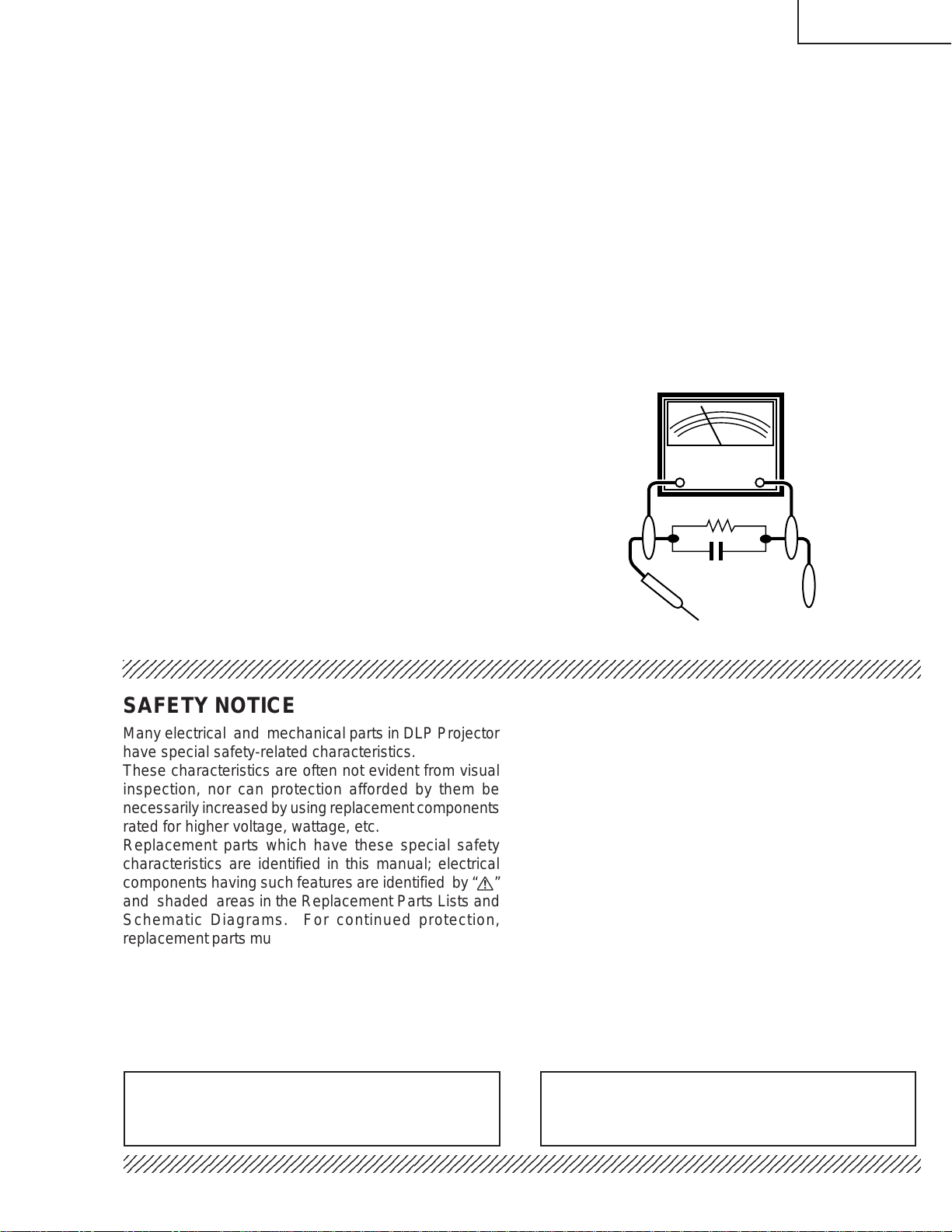
3. To be sure that no shock hazard exists, check for
current leakage in the following manner:
» Plug the AC cord directly into a 120-volt AC outlet,
(Do not use an isolation transformer for this test).
» Using two clip leads, connect a 1.5k ohm, 10 watt
resistor paralleled by a 0.15µF capacitor in parallel
between all exposed metal cabinet parts and earth
ground.
» Use an AC voltmeter with sensitivity of 5000 ohm per
volt., or higher, sensitivity to measure the AC voltage
drop across the resistor (See Diagram).
» All checks must be repeated with the AC plug
connection reversed. (If necessary , a non-polarized
adapter plug must be used only for the purpose of
completing these checks.)
Any reading of 0.3 volts RMS (this corresponds to
0.2 milliamp. AC.) or more is excessive and indicates
a potential shock hazard which must be corrected
before returning the unit to the owner.
AC
VOLTMETER
1.5k ohm (10W)
0.15µF
TEST PROBE
TO EXPOSED
METAL PARTS
CONNECT TO KNOWN
EARTH GROUND
1234567890123456789012345678901212345678901234567890123456789012123456789012345678901234567890121
SAFETY NOTICE
Many electrical and mechanical parts in DLP Projector
have special safety-related characteristics.
These characteristics are often not evident from visual
inspection, nor can protection afforded by them be
necessarily increased by using replacement components
rated for higher voltage, wattage, etc.
Replacement parts which have these special safety
characteristics are identified in this manual; electrical
components having such features are identified by “å”
and shaded areas in the Replacement Parts Lists and
Schematic Diagrams. For continued protection,
replacement parts must be identical to those used in the
original circuit. The use of a substitute replacement parts
which do not have the same safety characteristics as
the factory recommended replacement parts shown in
this service manual, may create shock, fire or other
hazards.
AVIS POUR LA SECURITE
De nombreuses pièces, électriques et mécaniques, dans
les projecteur à DLP présentent des caractéristiques
spéciales relatives à la sécurité, qui ne sont souvent
pas évidentes à vue.
Le degré de protection ne peut pas être nécessairement
augmentée en utilisant des pièces de remplacement
étalonnées pour haute tension, puissance, etc.
Les pièces de remplacement qui présentent ces
caractéristiques sont identifiées dans ce manuel;
les pièces électriques qui présentent ces particularités
sont identifiées par la marque “å” et hachurées dans la
liste des pièces de remplacement et les diagrammes
schématiques. Pour assurer la protection, ces pièces
doivent être identiques à celles utilisées dans le circuit
d’origine. L’utilisation de pièces qui n’ont pas les mêmes
caractéristiques que les pièces recommandées par
l’usine, indiquées dans ce manuel, peut provoquer des
électrocutions, incendies ou autres accidents.
WARNING: The bimetallic component has the primary
conductive side exposed. Be very careful in
handling this component when the power is on.
234567890123456789012345678901212345678901234567890123456789012123456789012345678901234567890121
AVERTISSEMENT: La composante bimétallique dispose du
conducteur primaire dénudé. Faire
attention lors de la manipulation de cette
composante sous tension.
3
Page 4
XG-C40XU/XE
5
5
NOTE TO SERVICE
PERSONNEL
234567890123456789012345678901212345678901234
UV-RADIATION PRECAUTION
The light source, metal halide lamp, in the LCD
projector emits small amounts of UV-Radiation.
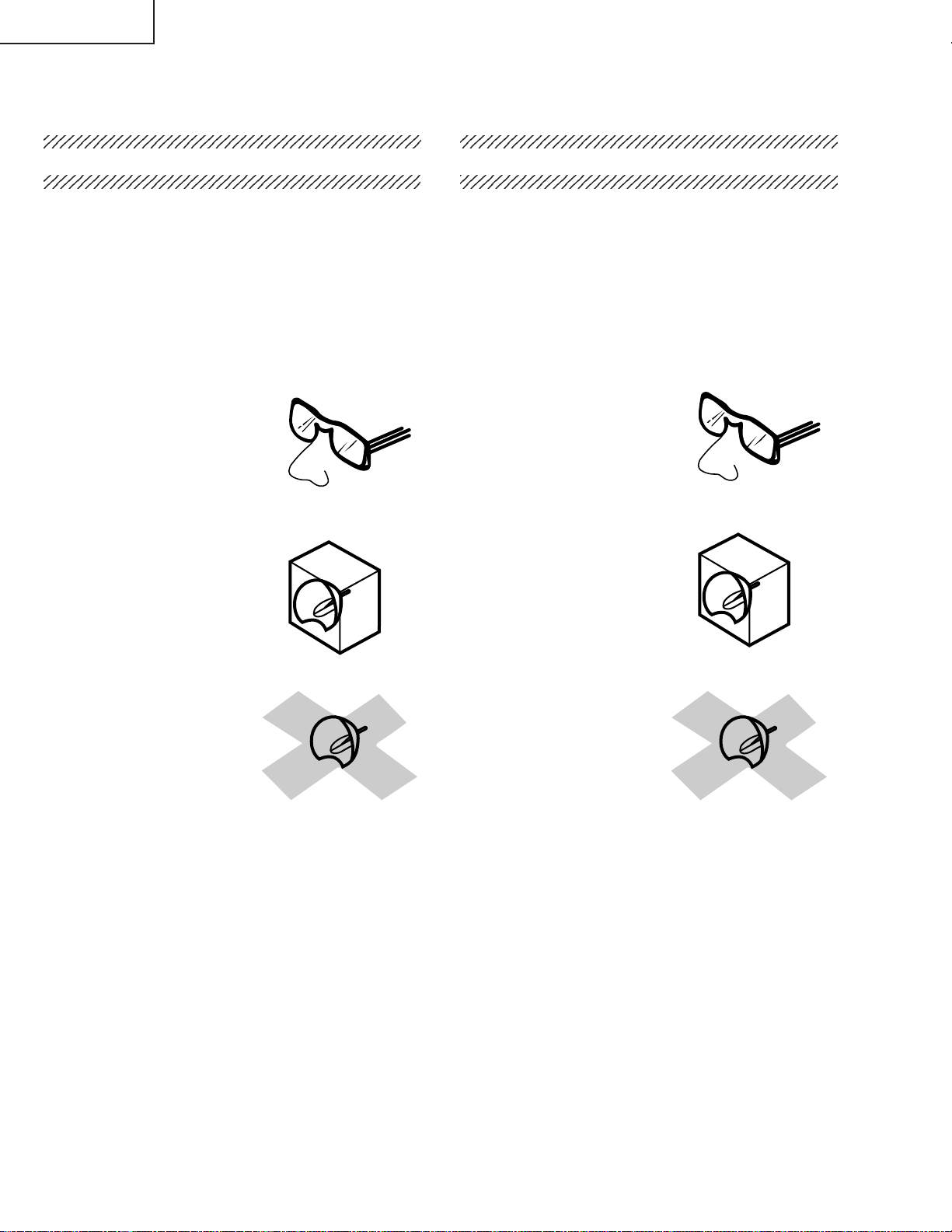
A VOID DIRECT EYE AND SKIN EXPOSURE.
To ensure safety please adhere to the following:
1. Be sure to wear sun-glasses when servicing the
projector with the lamp
turned “on” and the top
enclosure removed.
2. Do not operate the lamp outside of the lamp housing.
NOTE POUR LE PERSONNEL
D’ENTRETIEN
234567890123456789012345678901212345678901234
PRECAUTION POUR LES RADIATIONS UV
La source de lumière, la lampe mètal halide , dans le
projecteur LCD émet de petites quantités de
radiation UV.
EVITEZ TOUTE EXPOSITION DIRECTE
DES YEUX ET DE LA PEAU.
Pour votre sécurité, nous vous prions de respecter
les points suivants:
1. Toujours porter des lunettes de soleil lors d’un
entretien du projecteur
avec la lampe allumée
et le haut du coffret retiré.
2. Ne pas faire fonctionner la lampe à l’extérieur du
boîtier de lampe.
3. Do not operate for more than 2 hours with the
enclosure removed.
UV-Radiation and Medium Pressure
Lamp Precautions
1. Be sure to disconnect the AC plug when replacing
the lamp.
2. Allow one hour for the unit to cool down before
servicing.
3. Replace only with same type lamp. Type
CLMPF0075CE01 or BQC-XGC40XU/1 rated 85V/
200W.
4. The lamp emits small amounts of UV-Radiation, avoid
direct-eye contact.
5. The medium pressure lamp involves a risk of
explosion. Be sure to follow installation instructions
described below and handle the lamp with care.
3. Ne pas faire fonctionner plus de 2 heures avec le
coffret retiré.
Précautions pour les radiations UV
et la lampe moyenne pression
1. Toujours débrancher la fiche AC lors du
remplacement de la lampe.
2. Laisser l’unité refroidir pendant une heure avant de
procéder à l’entretien.
3. Ne remplacer qu’avec une lampe du même type.
Type CLMPF0075CE01 or BQC-XGC40XU/1,
caractéristique 85V/200W.
4. La lampe émet de petites quantités de radiation UV éviter tout contact direct avec les yeux.
5. La lampe moyenne pression implique un risque
d’explosion. Toujours suivre les instructions
d’installation décrites ci-dessous et manipuler la
lampe avec soin.
4
Page 5
XG-C40XU/XE
4
5
SHARP
UV-RADIATION PRECAUTION (Continued)
23456789012345678901234567890121234567890123
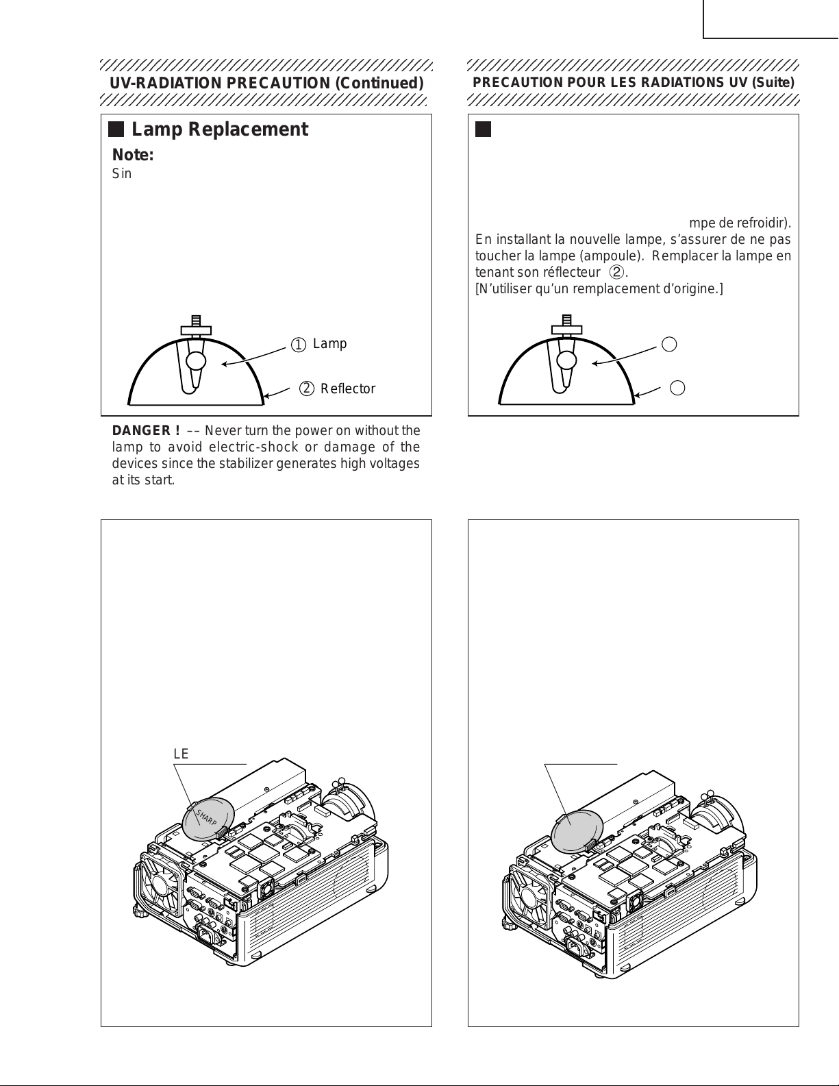
Lamp Replacement
Note:
Since the lamp reaches a very high temperature
during units operation replacement of the lamp
should be done at least one hour after the power
has been turned off. (to allow the lamp to cool off.)
Installing the new lamp, make sure not to touch the
lamp (bulb) replace the lamp by holding its reflector
2.
[Use original replacement only.]
Lamp
1
2
Reflector
DANGER ! –– Never turn the power on without the
lamp to avoid electric-shock or damage of the
devices since the stabilizer generates high voltages
at its start.
PRECAUTION POUR LES RADIATIONS UV (Suite)
234567890123456789012345678901212345678901234
Remplacement de la lampe
Remarque:
Comme la lampe devient très chaude pendant le
fonctionnement de l’unité, son remplacement ne doit
être effectué au moins une heure après avoir coupé
l’alimentation (pour permettre à la lampe de refroidir).
En installant la nouvelle lampe, s’assurer de ne pas
toucher la lampe (ampoule). Remplacer la lampe en
tenant son réflecteur 2.
[N’utiliser qu’un remplacement d’origine.]
Lamp
1
2
Reflector
DANGER ! –– Ne jamais mettre sous tension sans
la lampe pour éviter un choc électrique ou des
dommages des appareils car le stabilisateur génère
de hautes tensions à sa mise en route.
Since small amounts of UV-Radiation are emitted
from an opening between the duct cover and the
lamp housing, it is recommended to place the LENS
CAP on the opening during servicing to avoid eye
and skin exposure (Fig. 1).
Note: Please obtain a lens cap before servicing a
model XG-C40XU that is received without
one.
LENS CAP
SHARP
Comme de petites quantités de radiation UV sont
émises par une ouverture entre le couvercle du conduit et le botier de la lampe,il est recommandé de
placer le CAPUCHON D'OPTIQUE sur l'ouverture
pendant l'entretien pour éviter une exposition des
yeux et la peau (Fig. 1).
Remarque: Priére de se procurer un capuchon
d'optique acant d'entretien un modéle
XG-C40XU qui est livré sans.
LENS CAP
Figure 1.
Figure 1.
5
Page 6
XG-C40XU/XE
WARNING: High brightness light source, do not stare into the beam of light, or view directly . Be especially
careful that children do not stare directly in to the beam of light.
WARNING: TO REDUCE THE RISK OF FIRE OR ELECTRIC SHOCK, DO NOT EXPOSE THIS UNIT TO
MOISTURE OR WET LOCATIONS.
CAUTION
RISK OF ELECTRIC SHOCK.
DO NOT REMOVE SCREWS
EXCEPT SPECIFIED USER
SERVICE SCREW
CAUTION: TO REDUCE THE RISK OF ELECTRIC SHOCK,
DO NOT REMOVE CABINET.
NO USER-SERVICEABLE P ARTS EXCEPT LAMP UNIT.
REFER SERVICING TO QUALIFIED SERVICE
PERSONNEL.
The lighting flash with arrowhead within a
triangle is intended to tell the user that
parts inside the product are risk of electric
shock to persons.
The exclamation point within a triangle is
intended to tell the user that important
operating and servicing instructions are in
the manual with the projector.
CAUTION
(INLET Unit)
For continued protection
against a risk of fire,
replace only with same
5A 250V
A VERTISSEMENT : Source lumineuse de grande intensité. Ne pas fixer le faisceau lumineux ou le regarder
type 5A 250V fuse.
(F761)
directement. Veiller particulièrement à éviter que les enfants ne fixent directement le
faisceau lumineux.
A VERTISSEMENT : AFIN D’EVITER TOUT RISQUE D’INCENDIE OU D’ELECTROCUTION, NE P AS PLACER
CET APPAREIL DANS UN ENDROIT HUMIDE OU MOUILLE.
ATTENTION
RISQUE
D’ELECTROCUTION NE
PASRETIRER LES VIS, A
L’EXCEPTION DES VIS DE
REPARATION UTILISATEUR
SPECIFIEES
L’éclair terminé d’une flèche à l’intérieur
d’un triangle indique à l’utilisateur que les
pi‘eces se trouvant dans l’appareil sont
susceptibles de provoquer une décharge
électrique.
Le point d’exclamation à l’intérieur d’un
ATTENTION: POUR EVITER TOUT RISQUE
D’ELECTROCUTION, NE PAS RETIRER LE CAPOT.
AUCUNE DES PIECES INTERIEURES N’EST REP ARABLE
PAR L’UTILISATEUR, A L’EXCEPTION DE L’UNITE DE
LAMPE. POUR TOUTE REPARATION, S’ADRESSER A UN
TECHNICIEN D’ENTRETIEN QUALIFIE.
triangle indique à l’utilisateur que les
instructions de fonctionnement et
d’entretien sont détaillées dans les
documents fournis avec le projecteur.
PRECAUTION
(Unite d’admission)
Pour une protection continue
contre les risques d’incendie,
ne remplacer qu’avec un
5A 250V
fusible 5A 250V du même
type.
(F761)
6
Page 7
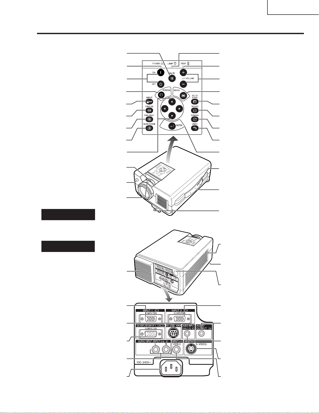
Location of Controls
Projector
Foot release
VOLUME buttons (+ / – )
MENU button
ENTER button
UNDO button
GAMMA button
RESIZE button
AUTO SYNC button
MUTE button
KEYSTONE button
BLACK SCREEN button
ENLARGE button
FREEZE button
INPUT button
POWER buttons (ON/OFF)
POWER indicator
ADJUSTMENT buttons
TEMPERATURE WARNING
indicator
LAMP REPLACEMENT
indicator
Carrying handle
Zoom knob
Remote control sensor
Kensington Security Standard
connector
Front and Top View
Side and RearView
INPUT 1 port (HD 15)
Cooling fan (Exhaust vent)
RS-232C port (9-pin Mini DIN)
AUDIO INPUT 3 terminals (RCA)
OUTPUT port for INPUT 1, 2 (HD 15)
Speaker
AC socket
INPUT 2 port (HD 15)
AUDIO OUTPUT terminal
(3.5mm stereo minijack)
AUDIO INPUT terminal
for INPUT 1, 2
(3.5 mm stereo minijack)
S-VIDEO INPUT 4 terminal
(4-pin Mini DIN)
VIDEO INPUT 3 terminal
(RCA)
Focus knob
Air filter/Cooling fan (Intake vent)
Remote control sensor
('/"/\/|)
OPERATION MANUAL
XG-C40XU/XE
7
Page 8
XG-C40XU/XE
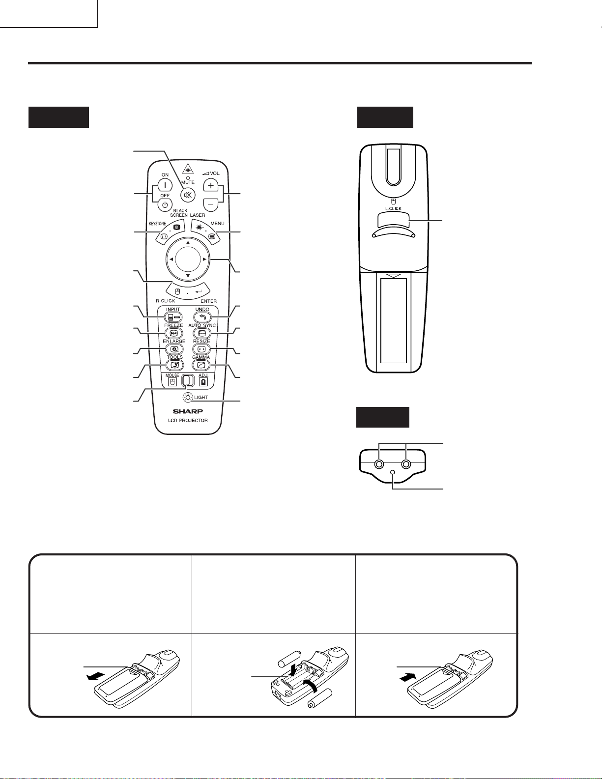
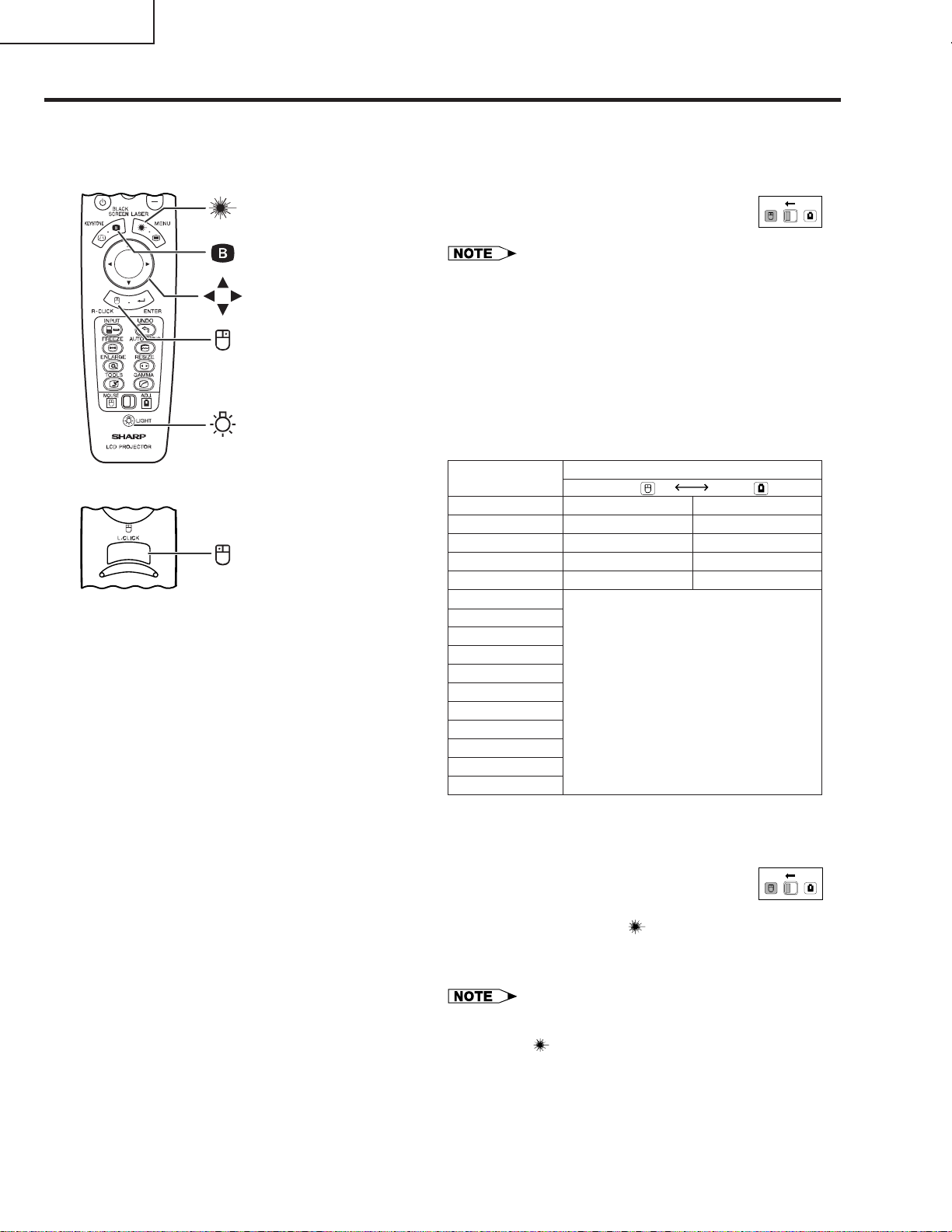
Operating the Wireless Mouse Remote Control
Remote Control
Front View Rear View
MUTE button
POWER buttons
(ON/OFF)
KEYSTONE/BLACK
SCREEN button
RIGHT-CLICK/
ENTER button
INPUT button
FREEZE button
ENLARGE button
TOOLS button
MOUSE/
ADJUSTMENT
switch
VOLUME buttons
( + / – )
LASER POINTER/
MENU button
MOUSE/
ADJUSTMENT
buttons ('/"/\/|)
UNDO button
AUTO SYNC button
RESIZE button
GAMMA button
BACKLIGHT button
LEFT-CLICK
button
Top View
Remote control
signal transmitter
Inserting the batteries
Press in on the arrow
1
mark and slide in the
direction of the arrow to
remove the battery cover.
Battery
cover
Insert two AA size
2
batteries, making sure
their polarities match the
+ and – marks inside
the battery compartment.
Battery
compartment
8
Laser
pointer
window
Insert the side tabs of
3
the battery cover into
their slots and press the
cover in until it is
properly seated.
Battery
cover
Page 9
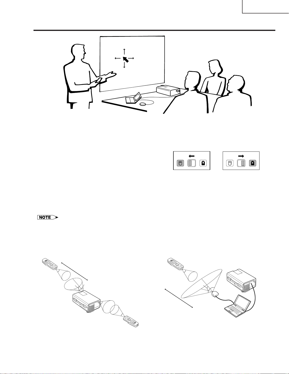
Using the Remote Control as a Wireless Mouse
XG-C40XU/XE
The remote control has the following three functions:
• Projector control
MOUSE/ADJUSTMENT switch
(Remote control)
• Wireless mouse
• Laser pointer
MOUSE
ADJ.
Wireless mouse
Laser pointer
MOUSE
ADJ.
Projector control
Remote Control/Mouse Receiver Positioning
• The remote control can be used to control the projector within the ranges shown below.
• The remote mouse receiver can be used with the remote control to control the mouse functions of a connected
computer within the ranges shown below.
• The signal from the remote control can be reflected off a screen for easy operation. However, the effective distance of the
signal may differ due to the screen material.
Controlling the Projector
Remote control
7 m
30˚
Using the Wireless Mouse
Remote control
30˚
45˚
30˚
4 m
45˚
30˚
Remote control
30˚
Remote
mouse
receiver
120˚
9
Page 10
XG-C40XU/XE
Effective buttons in MOUSE mode
Remote control
(Front view)
LASER POINTER
BLACK SCREEN
MOUSE
RIGHT-CLICK
BACKLIGHT
Remote control
(Rear view)
LEFT-CLICK
Use as a Wireless Mouse
Be sure the supplied remote mouse receiver is
connected to your computer.
(Slide the MOUSE/ADJUSTMENT switch on
the remote control to the MOUSE position.)
• The wireless mouse may not operate correctly if your
computer serial port is not correctly set up. Refer to the
computer’s operation manual for details of setting up/
installing the mouse driver.
• For one-button mouse systems, use either the LEFT-CLICK
or RIGHT-CLICK button.
Using the remote control in a dark room
Press BACKLIGHT, and the buttons will light up. Green
lights refer to mouse operations, and red lights to
projector adjustments.
Button name
LASER POINTER/MENU
BLACK SCREEN/KEYSTONE
RIGHT-CLICK/ENTER
MOUSE/ADJUSTMENT
LEFT-CLICK
POWER ON/OFF
VOLUME + / –
MUTE
INPUT
UNDO
FREEZE
AUTO SYNC
ENLARGE
RESIZE
TOOLS
GAMMA
Position of MOUSE/ADJUSTMENT switch
MOUSE
LASER POINTER (GREEN)
BLACK SCREEN (GREEN)
RIGHT-CLICK (GREEN)
MOUSE (NOT LIT)
ON (NOT LIT)
MENU (RED)
KEYSTONE
ENTER (RED)
ADJUSTMENT (NOT LIT)
ON (RED)
ADJ.
MOUSE
(RED)
—
ADJ.
Use as a Laser Pointer
(Slide the MOUSE/ADJUSTMENT switch on
the remote control to the MOUSE position.)
Press LASER POINTER ( ) to activate the laser
pointer. When the button is released, the light
automatically goes off.
• For safety, the laser pointer automatically goes off after 1
minute of continuous use. To turn it on, release LASER
POINTER ( ) and press again.
10
MOUSE
ADJ.
Page 11
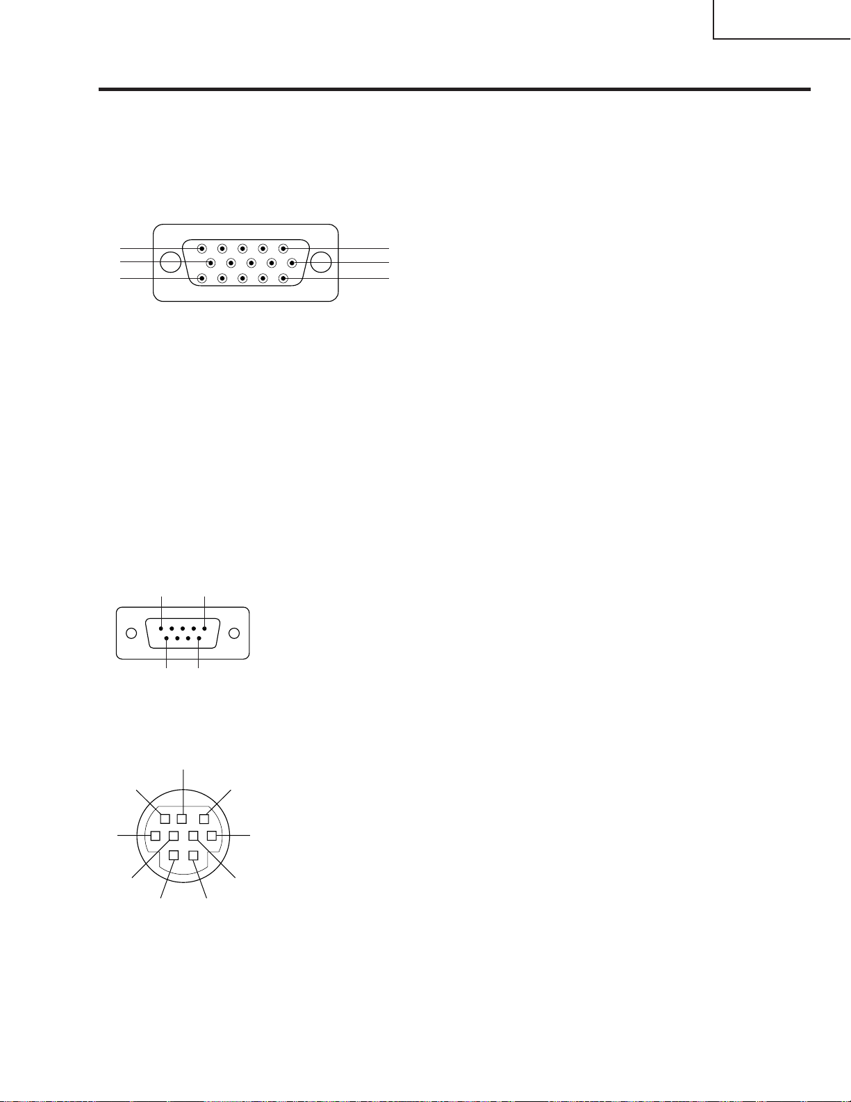
Connection Pin Assignments
Analog Computer 1 and 2 Signal Input Ports: 15-pin mini D-sub female connector
Computer Input
Analog
10
15
1. Video input (red)
2. Video input
(green/sync on green)
5
1
6
11
3. Video input (blue)
4. Reserve input 1
5. Composite sync
6. Earth (red)
7. Earth (green/sync on green)
8. Earth (blue)
Component Input
R
(CR)
1. P
2. Y
B
3. P
4. Not connected
5. Not connected
R
6. Earth (P
7. Earth (Y)
8. Earth (P
)
B
)
9. Not connected
10. GND
11. GND
12. Bi-directional data
13. Horizontal sync signal
14. Vertical sync signal
15. Data clock
9. Not connected
10. Not connected
11. Not connected
12. Not connected
13. Not connected
14. Not connected
15. Not connected
XG-C40XU/XE
RS-232C Port: 9-pin D-sub male connector of the DIN-D-sub RS-232C cable
Pin No. Signal Name I/O Reference
1
5
9
6
1 CD Not connected
2 RD Receive Data Input Connected to internal circuit
3 SD Send Data Output Connected to internal circuit
4 ER Not connected
5 SG Signal Ground Connected to internal circuit
6 DR Data Set Ready Output Not connected
7 RS Request to Send Output Connected to internal circuit
8 CS Clear to Send Input Connected to internal circuit
9 CI Not connected
RS-232C Terminal: 9-pin Mini DIN female connector
8
9
7
6
5
2
4
1
Pin No. Signal Name I/O Reference
1 VCC + 3.3V (Reserved) Output Not connected
2 RD Receive Data Input Connected to internal circuit
3 SD Send Data Output Connected to internal circuit
4 EXIR Detector of Option Unit Input Not connected
3
5 SG Signal Ground Connected to internal circuit
6 ERX IR Receive Signal from Input Not connected
7 RS Request to Send Output Connected to internal circuit
8 CS Clear to Send Input Connected to internal circuit
9 ETX IR Transmit Signal Output Not connected
(Reserved)
IR Amplifier (Reserved)
(Reserved)
11
Page 12

XG-C40XU/XE
Dimensions
(124.5)
64
/
1
(138.5) 49
64
/
33
54
(33.5)
16
/
5
1
(237.5)
32
/
11
9
Rear Vie
Top View
25
/64 (10)
53
/64 (97.5)
3
(27.5)
64
/
5
1
(61)5
32
/
13
2
(142)
32
/
19
(61)4
32
/
13
2
(23)
32
/
29
13
(310)5
64
/
12
(358.4)
64
/
7
14
3 51/64 (96.5)
23
/64 (9)
23
/64 (9)
(262)
16
/
5
10
Side View
(83)
64
/
17
3
(93)
32
/
21
3
(30)
16
/
13
1
63
/64 (25)
w
9 19/32 (243.5)
1
/64 (229)
9
7
/16 (11)
(16)
8
/
5
13
/32 (10.5)
(121)
64
(134)
/
32
/
49
9
(13)
32
/
17
Bottom View
11
1
/16 (43)
Front View
2
3
63
/64 (76)
17
/64 (83)
12
Units: inches (mm)
Page 13

REMOVING OF MAJOR PARTS
1.Removing the Intake cover and lamp unit
1-1. Detach the Intake cover.
1-2. Loosen the lamp cover screw and draw out the lamp cover in the direction of arrow (toward yourself).
1-3. Remove the two lamp unit lock screws. Detach the lamp unit.
SHARP
XG-C40XU/XE
Intake cover
Note:
When replacing the lamp, make sure
that there is a clearance of over
8mm between the terminal and the
lamp snap-on spring (and other
metallic parts).
Lamp unit
1-3
1-3
1-2
1-1
Lamp cover
13
Page 14
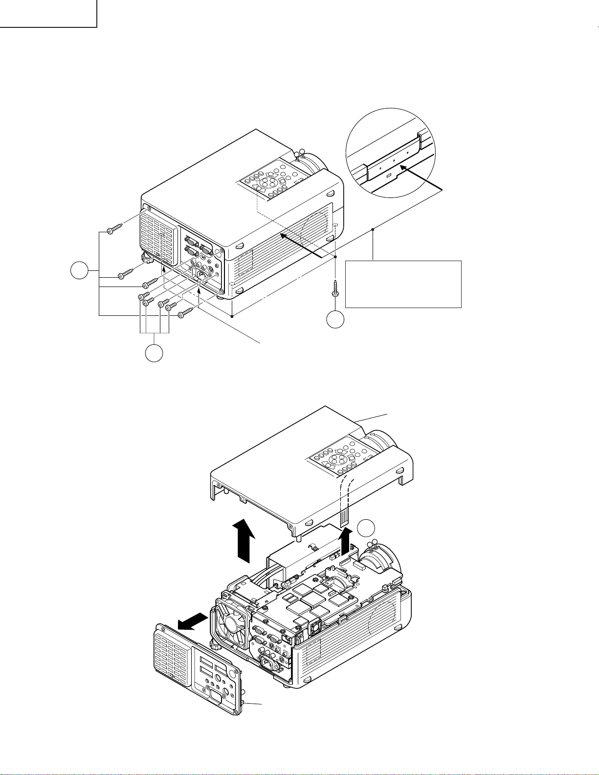
XG-C40XU/XE
2.Removing the top and rear cabinets
2-1. Remove the four rear cabinet lock screws.
2-2. Remove the four terminal board lock screws off the rear cabinet. Unhook and detach the rear cabinet from
below.
2-3. Remove the four top cabinet lock screws from below.
SHARP
2-1
Press both sides of the bottom
cabinet in the directions of
arrow to undo the hooks. Lift
and detach the top cabinet.
2-3
Hook
2-2
2-4. Slowly lift the top cabinet and disconnect the operation key unit connector (KY). Then take away the top
cabinet.
Top cabinet
(KY)
2-4
Rear cabinet
14
Page 15
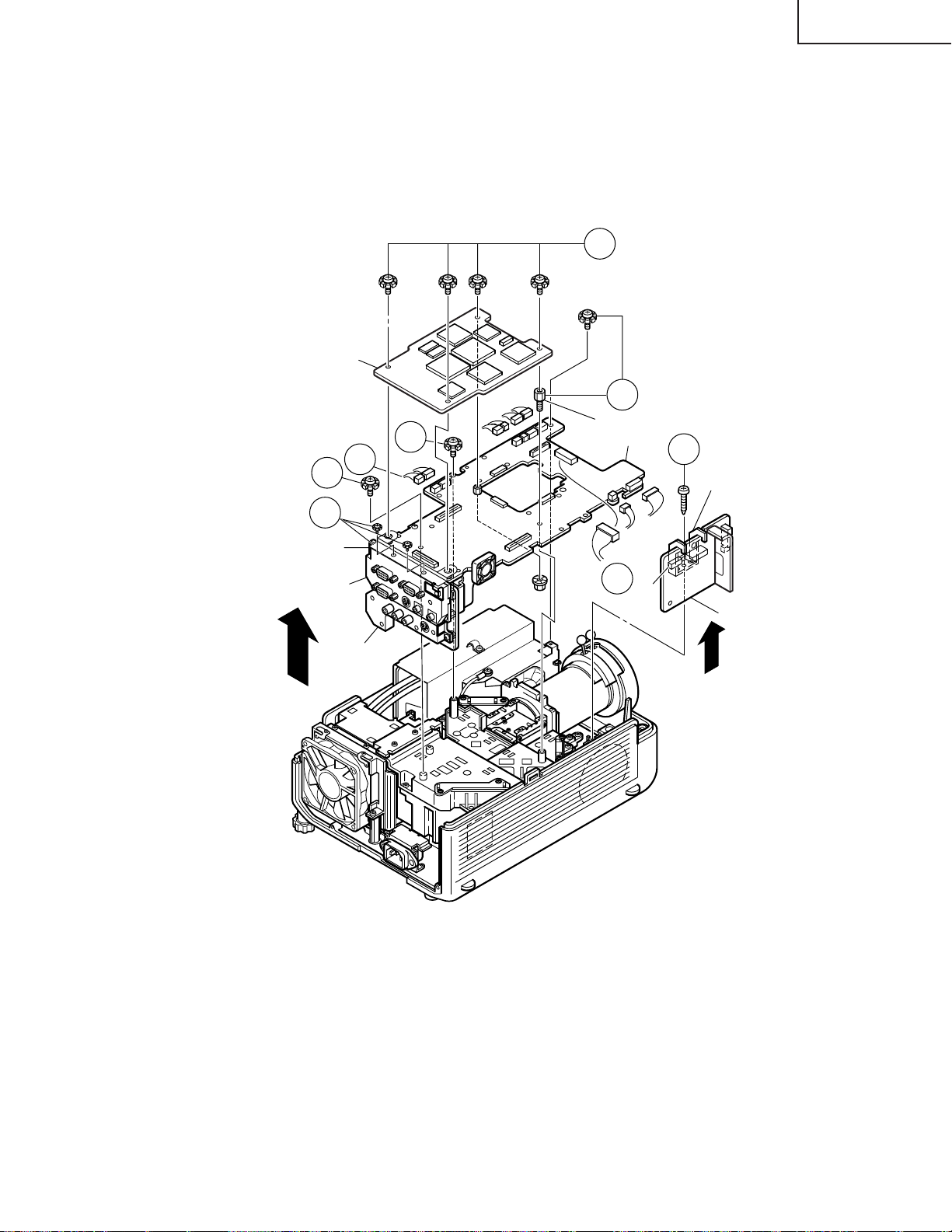
XG-C40XU/XE
3. Removing the PWB units
3-1. Disconnect the connectors from the output unit.
3-2. Remove the four PC I/F unit lock screws.
Remove the two screws and the earth shield, and take out the PC I/F unit.
3-3. Remove the spacer (stud bolt) and the three screws off the output unit. Lift the output unit, together with the
signal unit, off the position.
3-4. Remove the S-out/REG unit angle lock screw and take out the S-out/REG unit.
3-2
PC I/F Unit
3-3
3-2
Signal Unit
PC Terminal Unit
Video Unit
3-1
(FP)
3-3
(FS)
(L)
(Q)
(TP)
(FN)
3-3
Spacer (stud bolt)
Output Unit
(EB)
(EB)
3-1
(F)
(SO)
(SO)
3-4
S-out/REG Unit Angle
(EA)
(SP)
S-out/REG Unit
15
Page 16
XG-C40XU/XE
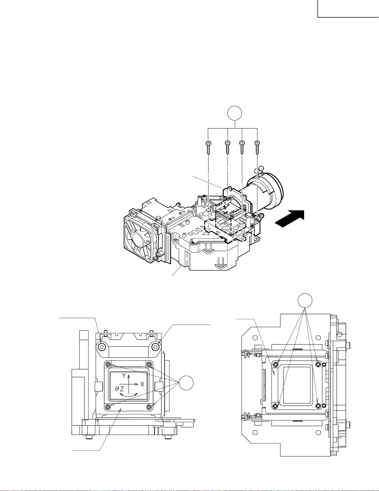
4.Removing the optical mechanism unit
4-1. Remove the six optical mechanism unit lock screws. Lift the unit off the position.
4-2. Remove the two lamp socket holder lock screws and take out the holder.
Duct Fan Unit
4-2
4-1
Optical Mechanism Unit
16
Page 17

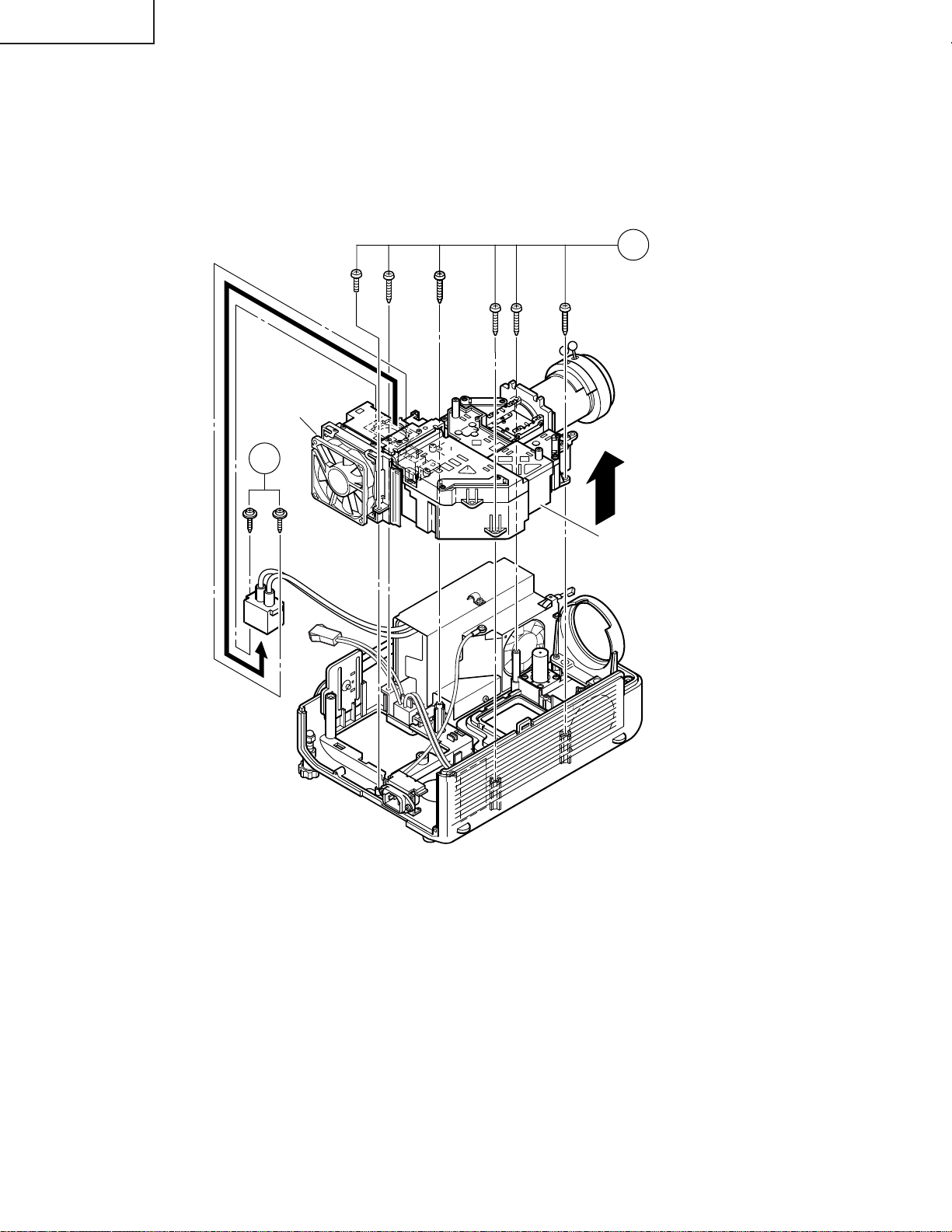
5.Removing the Power/Ballast unit assembly
5-1. Remove the Power/Ballast unit assembly lock screw.
5-2. Remove the (FG) lead lock screw.
5-3. Lift the Power/Ballast unit assembly off the position.
6.Removing the ballast unit and inlet unit
6-1. Disconnect the connector (PA) from the inlet unit. Take out the AC power switch.
6-2. Remove the Inlet unit lock screw.
6-3. Pull the inlet unit toward yourself off the position.
Note: Before installing the lamp cover, make sure the AC power switch is at the " " (OFF) position.
XG-C40XU/XE
AC power switch
(for Lamp replacement)
6-1
5-1
(FG)
5-2
Power/Ballast Unit Ass'y
(TP)
5-3
(BA)
(PA)
(FG)
6-2
(PA)
6-3
Inlet Unit
17
Page 18
XG-C40XU/XE
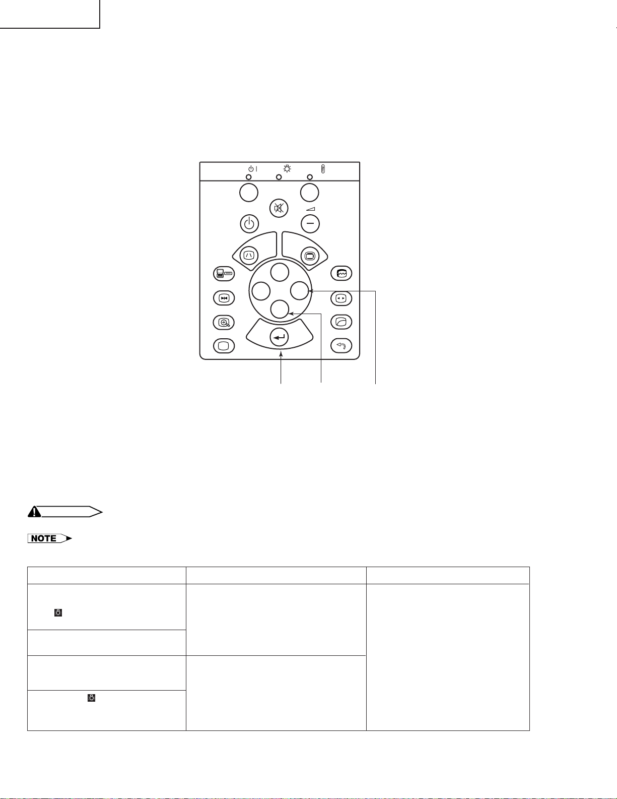
RESETTING THE TOTAL LAMP TIMER
When the lamp has been replaced, reset the total lamp timer in the following steps.
Resetting procedure
1. While holding down the “ENTER”, “ADJ."” and “ADJ.|” keys on the set at the same time, turn on the main
power switch (located side the AC inlet).
2. Now the total lamp timer is reset to zero. “000H” appears on the screen.
POWER
ON
OFF
INPUT
FREEZE
ENLARGE
BLACK SCREEN
B
LAMP
MUTE
I
KEYSTONE
'
ENTER ADJ." ADJ.|
TEMP.
+
VOLUME
MENU
AUTO
'
'
'
ENTER
SYNC
RESIZE
GAMMA
UNDO
Lamp
The lamp in this projector operates for approximately 2,000 cumulative hours, depending on the usage environment. It is recommended that the lamp be replaced after 1,900 cumulative hours of use or when you notice a
significant deterioration of the picture and colour quality. The lamp usage time can be checked with the On-screen
Display.
CAUTION
• Intense light hazard. Do not attempt to look into the aperture and lens while the projector is operating.
• As the usage environment can vary significantly, the projector lamp may not operate for 2,000 hours.
Condition
The LAMP REPLACEMENT
indicator lights up red, and “LAMP”
and “ ” will flash in yellow in the
lower-left corner of the picture.
A significant deterioration of the
picture and colour quality occurs.
The power will automatically turn
off and the projector will enter
standby mode.
Problem
• Lamp has been used for over 1,900
hours.
• Lamp has been used for over 2,000
hours.
• Purchase a replacement lamp unit
(lamp/cage module) of the current
type BQC-XGC40XU/1 from your
nearest Sharp Authorised LCD
Projector Dealer or Service Centre.
• Replace the lamp. If you wish, you
may have the lamp replaced at
your nearest Sharp Authorised
LCD Projector Dealer or Service
Centre.
Possible Solution
“LAMP” and “ ” will flash in red in
the lower-left corner of the picture,
and the power will turn off.
18
Page 19

THE OPTICAL UNIT OUTLINE
Layout of the optical system
Note: Layout for positioning the optical system.
Incident polarizing plate B
XG-C40XU/XE
Projection Lens
M4/M6
Dichroic coating
(B reflection)
UV-filter(0.8t)
UV-filter
Dichroic coating
(B reflection)
M4/M6
AR coating
B reflector
Relay lens 3
Relay lens 2
B reflector
BLUE
RL3
RL2
emergent polarizing
B-LCD
G-LCD
Dichroic coating
(G transmission)
CL3
RL1
Relay lens 1
plate B
Cross dichroic prism
Porarizing film
Condenser lens G
GREEN
BLUE
G reflector
M3
UV-IR coating
Marking
emergent polarizing plate R
Dichroic coating (R transmission)
R-LCD
R-reflector
CL2
Condenser lens R
emergent
polarizing plate G
Marking
(Bottom)
Dichroic coating
Porarizing film
M5
Dichroic coating
(R reflection)
RED
M2
B/G reflector
DC lamp
(Light source)
PBS(polarization
beam splitter)
Ag-deposited
face
Fly-eye lens (outgoing light)
Fly-eye aperture
Fly-eye lens (incoming light)
19
CL1
M1
Ag-coated mirror W
Page 20

XG-C40XU/XE
CONVERGENCE AND FOCUS ADJUSTMENT
» Start the convergence and focus adjustments with the top panel removed but the power
on. Use the remote control to adjust the image.
Take the following procedures.
1. Focusing the projection lens
(A) Replacing all the 3 LCD panels
1. Before replacing all the 3 LCD panels, project an image on the screen and bring it into focus.
2. Replace the LCD panels with new ones. But until the focus has been completely readjusted, be careful not
to change the projection distance between the set and the screen, nor to move the projection lens focus
and zoom rings.
Note:
If the focus is readjusted with a different positional relation, the relation between the projection distance
and the screen size is affected. In other words, a short-distance image (40 WIDE for example) may get out
of the focus range, or a long-distance image (300 WIDE for example) may come out of the focus.
(B) Replacing 1 or 2 of the 3 LCD panels
1. In adjusting the focus after replacement of one or two LCD panels, project an image on the screen and turn
the projection lens focus ring to get the non-replaced LCD panel into focus.
2. But until the focus has been completely adjusted for the new LCD panels, be careful not to change the
projection distance between the set and the screen, nor to move the projection lens focus and zoom rings.
3. If the projection distance has been changed or the projection lens readjusted, repeat the above steps 1 and
2.
2. Focus adjustment
(A) Adjusting the G-LCD panel(Make this adjustment on the white-only screen.)
1. Adjustment in θX and Z directions .
Loosen the lock screw "a" and insert an eccentric screwdriver into the notch and hole "a". Turn the screwdriver
until the top, center and bottom on the screen get into focus. In adjusting this top-to-bottom focus, tighten
the lock screws "b" and "c" to fix the θY direction adjustment.
First get the right and left halves in balance. Then improve the accuracy while making the adjustment 2
below.
2. Adjustment in θY direction
T emporarily tighten the lock screw "a" and loosen the lock screws "b" and "c". Insert the eccentric screwdriver
into the notch and hole "c" for adjusting in the θY direction on the top of the screen. Insert the eccentric
screwdriver into the notch and hole "b" for adjusting in the θY direction on the bottom of the screen.
3. Repeat the above steps 1 and 2 to finely adjust the focus. Finally tighten up all the lock screws.
Notes :
1 Carefully proceed with the focus adjustment because the adjusting directions are correlated.
2 In adjusting the convergence and focus, do not move the projection lens zoom and focus rings until the end
of all the adjustments.
(B) Adjusting the B-LCD panel (Do the same for the R-LCD panel.)
1. Take the same procedure as for the G-LCD panel focus adjustment. Note that the adjustment range is
wider in the Z direction. If the convergence is quite different between the B-LCD and G-LCD panels,
roughly adjust the convergence first and then the focus.
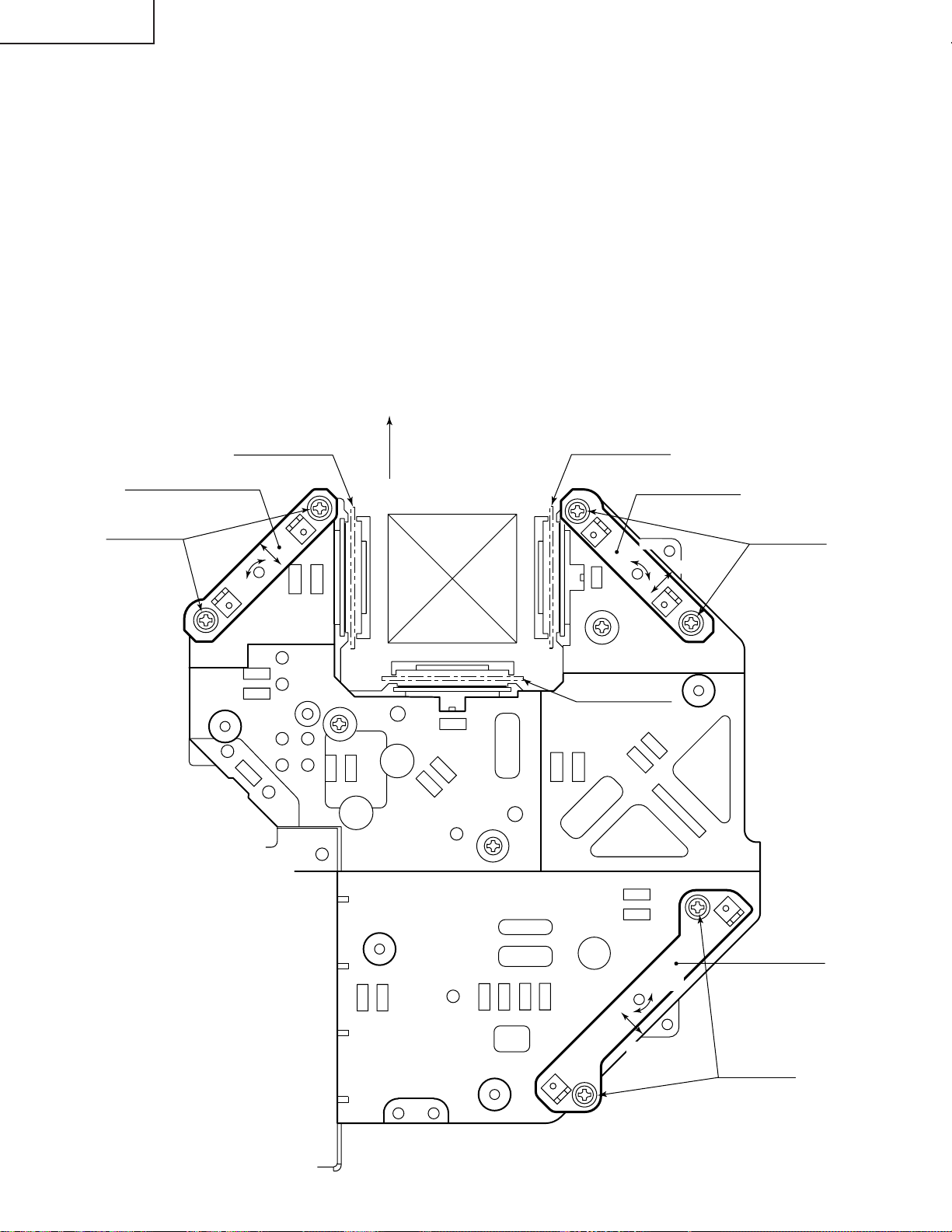
3. Convergence adjustment
» Use a crosshatch pattern signal for this adjustment.
Make the adjustment just for the G-LCD and the relevant colour.
1. Loosen the convergence lock screw "d".
2. Adjustment in Y and θZ directions
Put a hex wrench in the Y and θZ direction adjustment zone.
3. Adjustment in X direction
Put an eccentric cam adjusting wrench in the X direction adjustment zone.
20
Page 21
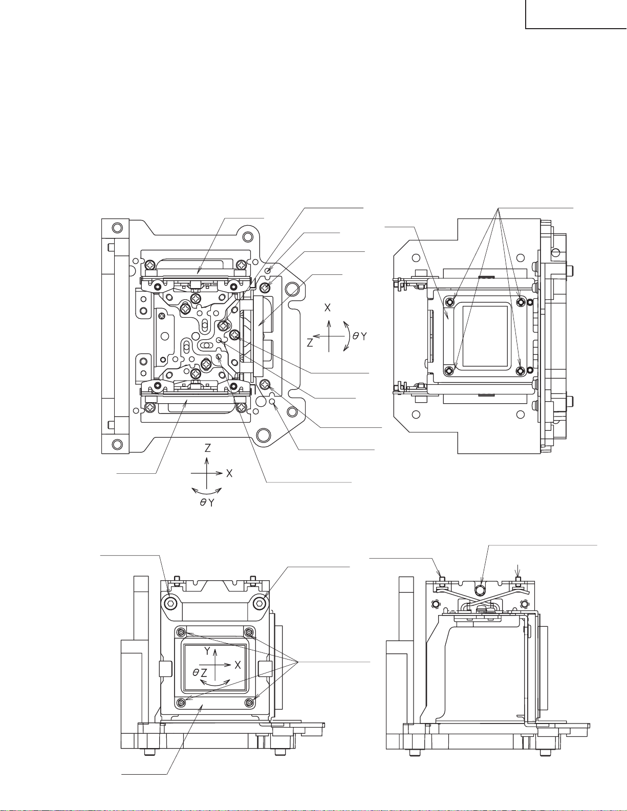
R-LCD
B-LCD
Lock screw "a"
Lock screw "c"
Notch and
hole "c"
Notch and
hole "b"
Lock screw "c"
G-LCD
G-LCD
Lock screw "b"
Notch and hole "c"
Notch and hole "a"
Lock screw "d"
Lock screw "d"
R·B-LCD panel
mounting screws
(four screws)
R·B-LCD
SIDE VIEW (from inside)
SIDE VIEW (from outside)
TOP VIEW SIDE VIEW
G-LCD panel
mounting screws
Eccentric cam
(Y direction adjustment)
Eccentric cam
(X direction adjustment)
Eccentric cam
(θZ direction adjustment)
(four screws)
4. With the G-LCD panel's screen center as refernce, adjust the R-LCD and B-LCD panels.
5. Finally tighten up the convergence lock screw "d".
Notes :
1 The eccentric cam is used for convergence adjustment.
This means that the cam's turning and the linear movement are not always uniform.
2 This model is not equipped with the LCD image adjustment mechanism. This is because the cross-dichroic
prism is used for image formation. When the LCD panels all get into best focus, the images are almost
completely converged.
Convergence and Focus Adjustments Mechanism
XG-C40XU/XE
21
Page 22
XG-C40XU/XE
80
2
2
92
5
7.5
0.5
min85
ø5
ø3.5
3.5
Convergence and Focus Adjustments at a Glance
Adjustment directions
Adjustment Direction Definition Direction of LCD panel
X direction LCD right and left
Convergence Y direction LCD top and bottom
θZ direction Rotation around Z axis LCD turning axis
Z direction LCD optical axis
Focus θX direction Rotation around X axis LCD top-to-bottom flapping
θY direction Rotation around Y axis LCD right-to-left flapping
Convergence and Focus Adjustment for the Optical Mechanism
Colour Adjustment Direction
X direction ±0.8mm Eccentric cam Eccentric cam adjusting wrench d Hex wrench
Convergence Y direction ±0.8mm Eccentric cam Eccentric cam adjusting wrench d Hex wrench
R/B θZ direction ±1° Eccentric cam Eccentric cam adjusting wrench d Hex wrench
colours Z direction ±0.8mm
Focus θX direction ±1°
θY direction ±1°
Z direction ±0.2mm
G colour Focus θX direction ±1° Same as for R and B colours
θY direction ±1°
Movement
Position Adjusting tool
Notch and hole "a" & "c"
Notch and hole "a" & "c"
Notch and hole "b" & "c"
Eccentric screwdriver, a, c
Bladed screwdriver a, c
Lock screw
b, c
Tightening tool
Phillips
screwdriver,
*Hex wrench
Focus Adjustments the Other Way
Lock screw Position Related direction
a Notch and hole "a" Z and θX directions
b Notch and hole "b" θY direction
c Notch and hole "c" Z, θX and θY directions
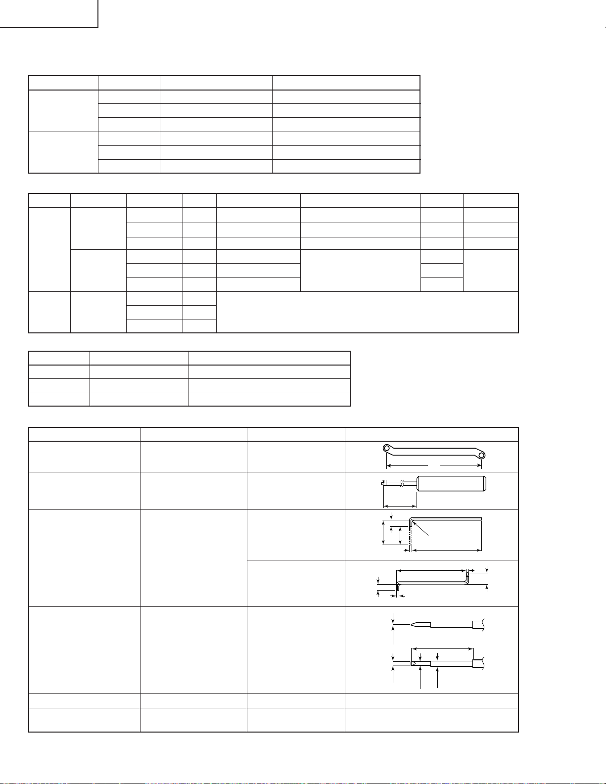
Convergence and Focus Adjusting and Tightening Tools
Tool Specific or General Tool code Configuration
Eccentric cam
adjusting wrench
Specific 9DASPN-XGNV1U
Eccentric screwdriver Specific 9DADRiVER-NV4U
9EQLNC-XGNV1U
Hex wrench General (redesigned)
9EQLNC-XGNV4U
100
5
16
CUT
R2
50
2
Bladed screwdriver General 9EQDRiVER-NV1B
Phillips screwdriver General — For M2.6 pan-head machine screw
*Hex wrench General —
22
1.27mm, preferably use a 70 mm or
longer screwdriver (with a handle).
Page 23
XG-C40XU/XE
Replacing the LCD panels
Detach the top panel and the optical mechanism unit in advance.
(1)Remove the four prism holder lock screws. Detach the prism holder from the optical mechanism unit.
(2)Remove the LCD panel lock screws (four each for the R-, G- and B-LCD panels). Detach the LCD panels from the
prism holder.
(3)Mount a new LCD panel in the reverse order of the above steps (1) and (2).
~ Readjust the convergence and focus. Note that the G-LCD panel needs no convergence adjustment and has
a small adjustment range in the Z direction.
1
Prism holder
SIDE VIEW (from inside)
Lock screw "d"
R·B-LCD
Optical Mechanism Unit
Lock screw "d"
2
R·B-LCD panel
mounting screws
SIDE VIEW
G-LCD
G-LCD panel
mounting screws
2
23
Page 24
XG-C40XU/XE
Adjusting the optical axis of the mirrors (M1, M5 and M4/M6)
The optical axis must be readjusted if an eclipse happens with the R. G or B mirrors. Generally speaking,
this adjustment is needed when any of the internal optical components has been replaced.
Adjustment procedure required when any of the panels has been replaced or the convergence has been
adjusted
(1)Disconnect the flat cables of all the LCD panels.
(2)Let the lamp light up.
(3)To adjust the G mirror, shield the R and B mirrors with shielding plates (You can use a business card or the like to
block the light).
(4)Loosen the lock screw of the M1 adjust lever.
(5)Looking at the G image on the screen, turn or slide the M1 adjust lever until the eclipse on the screen disappears.
Tighten up the screw.
(6)To adjust the R mirror, shield the G and B mirrors and adjust the M5 adjust lever. For the B mirror , shield the R and
G mirrors and adjust the M6 adjust lever.
(Take the same steps 4 and 5 above.)
(7)Remove all the shielding plates to have a white image.
Make sure there is no eclipse.
M4/M6
Lock screws
Shielding plate B
adjust lever
slide
turn
FRONT
Shielding plate R
M5 adjust lever
turn
Shielding plate G
Lock screws
slide
24
M1 adjust lever
turn
slide
Lock screws
Page 25

XG-C40XU/XE
ELECTRICAL ADJUSTMENT
Hook up a signal generator, or a DOSV or Mac personal computer to the projector in order to feed the
signals specified in the Adjusting conditions.
No. Adjusting point Adjusting conditions Adjusting procedure
1 EEPROM
initialization
1. Turn on the power (make
sure the lamp lights up) and
warm up the unit for 15 minutes.
» Make the following settings:
Press SW5101 to call up the process mode and
execute S2 in the SSS menu. Now the system,
with the PC board not included, is initialized. Do
not execute S1 because otherwise the PC board
will be initialized.
To adjust the PC board, follow the instruction in
"Adjusting the PC board". (See page 31)
2 3.3V power
supply
adjustment
3 2.5V power
supply
adjustment
4 R drive » Using the control switches or the remote controller
5 B drive 1. Feed the 100% blue-only
6 G drive 1. Feed the 100% green-only
1. Turn on the power.
2. Connect the digital voltmeter to TP1446.
1. Turn on the power.
2. Connect the digital voltmeter to TP1447.
1. Feed the 100% red-only signal. Make the following
choice.
Group : A/D
Subject : R-D
signal. Make the following
choice.
Group : A/D
Subject : B-D
signal. Make the following
choice.
Group : A/D
Subject : G-D
» Adjust R1649 so that the voltmeter should read
3.43 ±0.03 Vp-p.
» Adjust R1652 so that the voltmeter should read
2.60 ±0.05 Vp-p.
buttons, adjust the data so that the signal becomes bit-less (noise).
» Using the control switches or the remote controller
buttons, adjust the data so that the signal becomes bit-less (noise).
» Using the control switches or the remote controller
buttons, adjust the data so that the signal becomes
bit-less (noise).
7 RGB 1 system
black level
signal amplitude
(odd-numbered)
1. Make the following choice:
Group : OUTPUT 1
Subject : G1-BLK
G1-GAIN
For red, choose the sub-
jects R1-BLK and R1-GAIN.
For blue, choose the subjects B1-BLK and B1-GAIN.
2. Connect the oscilloscope to
TP1101 for red.
TP1201 for green
TP1301 for blue
25
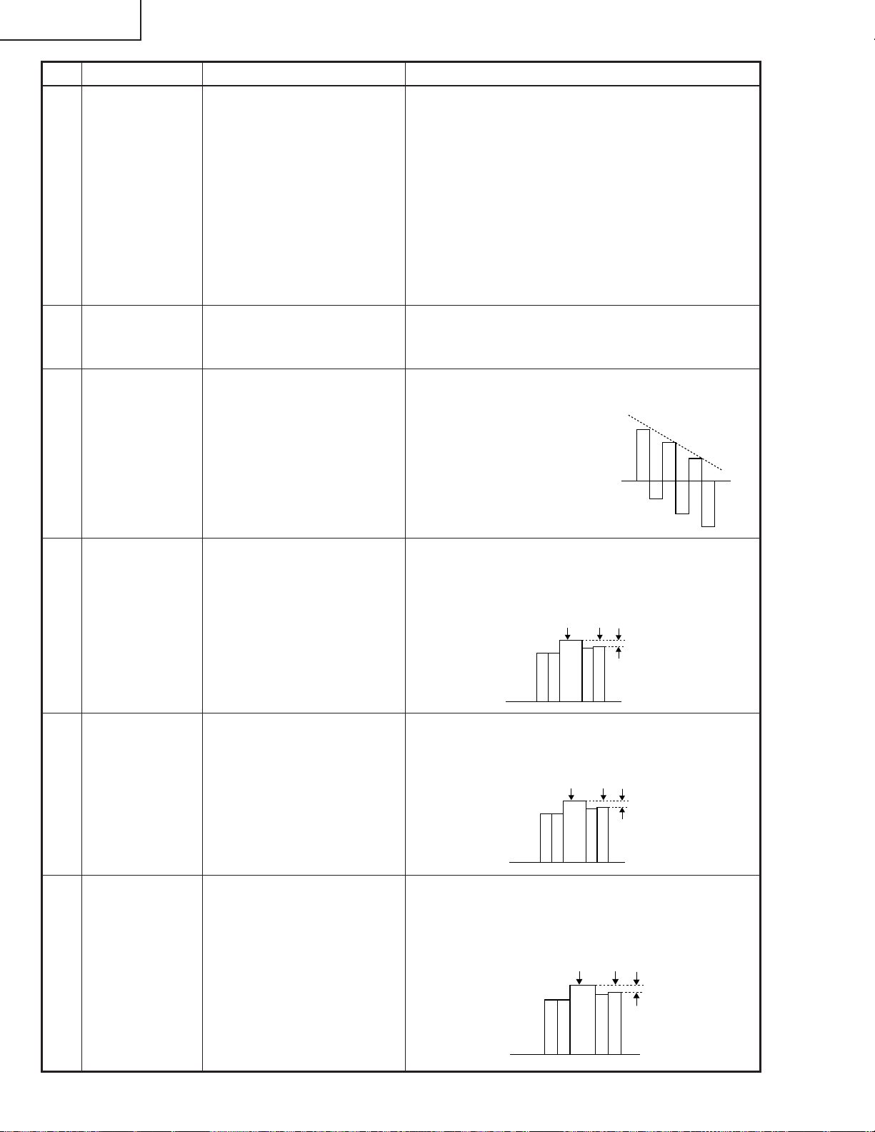
» Choose the subject G1-GAIN and adjust the sig-
nal amplitude to 3.3 ±0.1 Vp-p using the control
switches or the remote controller buttons.
» Next,choose the subject G1-BLK and adjust the
white to white level to 2.6 ±0.1V DC.
(Adjust to 2.6V
DC for red and
blue.)
» Adjust the signal's amplitude and white to white
level to 3.3 ± 0.1Vp-p and 2.6 ± 0.1V DC, respectively, for red and blue.
2.6V
3.3Vp-p
(Adjust to 3.3Vp-p
for green and blue.)
Page 26
XG-C40XU/XE
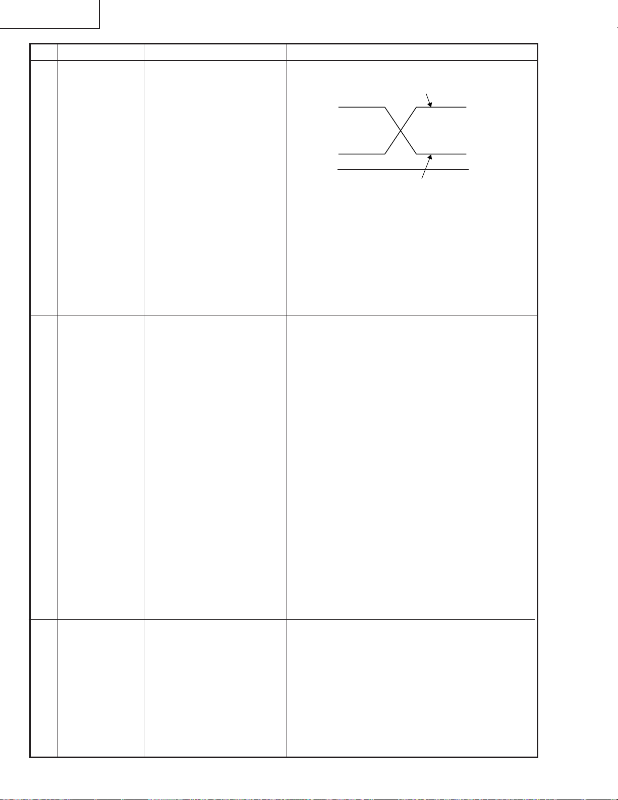
No. Adjusting point Adjusting conditions Adjusting procedure
8 P SIGNAL 1. Connect the oscilloscope to
TP1701 for red.
TP1702 for green
TP1703 for blue.
2. Make the following choice:
Group : OUTPUT 2
Subject : PSIG-H
: PSIG-L
9 Panel ghost
adjustment
1. Project the XGA60Hz ghost
test pattern (black charac-
ters in bold on the halftone
RGB background).
Group: OUTPUT3
2. GCK-PHASE adjustment
Make sure the setting is fixed
at 8 (initial value).
3. EN-WIDTH adjustment
Make sure the setting is fixed
at 8 (initial value).
4. ENR-PHASE adjustment (R-
LCD ghost adjustment)
5. ENG-PHASE adjustment
(G-LCD ghost adjustment)
6. ENB-PHASE adjustment (B-
LCD ghost adjustment)
» Adjust the PSIG waveform to the one shown below.
(Adjust with PSIG-H.)
PSIG
(Adjust with PSIG-L.)
» For the green and blue colours, make sure their wave-
forms are similar to that of the red colour.
» Make sure the pin stripe of every 12 dot doesn't ap-
pear at 10 steps signal of side nays.
(Appearing white pin stripe or black one, adjust the
PSIG-H.)
» ENR-PHASE adjustment (R-LCD ghost adjustment)
1 Increase the setting until a ghost image (see
Note) becomes visible at the left of the back
characters on the R half-tone background.
2 Lower the setting point by point until the left-
hand ghost image (1 above) disappears.
3 Further lower the setting by one point.
» ENG-PHASE adjustment (G-LCD ghost adjust-
ment)
Adjust the G ghost image by following the same
procedures described under step 1 above.
» ENB-PHASE adjustment (B-LCD ghost adjust-
ment)
Adjust the B ghost image by following the same
procedures described under step 1 above.
Note: Left-hand ghost image: Characters are shown
double 12 dots left from the real characters.
Reference: This adjustment is made because the
EPSON LCD panel may have 1- or 2point differences due to lot-by-lot variations.
6.2±0.2V DC
2.0V DC
GND
10 Sample-and-
hold pulse
phase
RCK-PHASE
GCK-PHASE
BCK-PHASE
1. Feed the XGA mode 75-Hz
black signal.
2. Make the following choice:
Group : OUTPUT 3
Subject : SH-PHASE
(Have the standard level at
2.)
Fix the RCK-, GCK- and
BCK-PHASE settings all to
8.
» Using the control switches or the remote controller
buttons, make sure that the “OUTPUT 3” characters are not blurry and there is no ghost image. If
such blur or ghost occurs, finely adjust the setting
in the range of 7~9.
26
Page 27
1
2
No. Adjusting point Adjusting conditions Adjusting procedure
XG-C40XU/XE
11 RGB counter-
voltage
adjustment
12 RGB gradation
regeneration
adjustment
1. Feed the black-and-red
(25%) stripe signal (XGA).
2. Make the following choice:
Group : OUTPUT 3
Subject : RC (R)
and
Group : OUTPUT 3
Subject : RC-INV (R)
1. Feed the green-only SMPTE
pattern signal (XGA).
Group : OUTPUT 1
Subject : G1-BLK
» Using the control switches or the remote controller
buttons, adjust the data in order to minimize the
flicker.
» Make the same adjustment for BC (B), GC (G),
RC-INV (B) and RC-INV (G).
» See if the image is equally adjusted at the center
and both sides of the screen. If not, readjust the
setting to have the image equal at right and left.
» Adjust the G-BLK data until the gradation of the
portion 1 (95% and 100% white) shown below
can be slightly recognized. Make sure also that the
gradation of the portion 2 (0% and 5% black) is
visible.
13 RGB white
balance
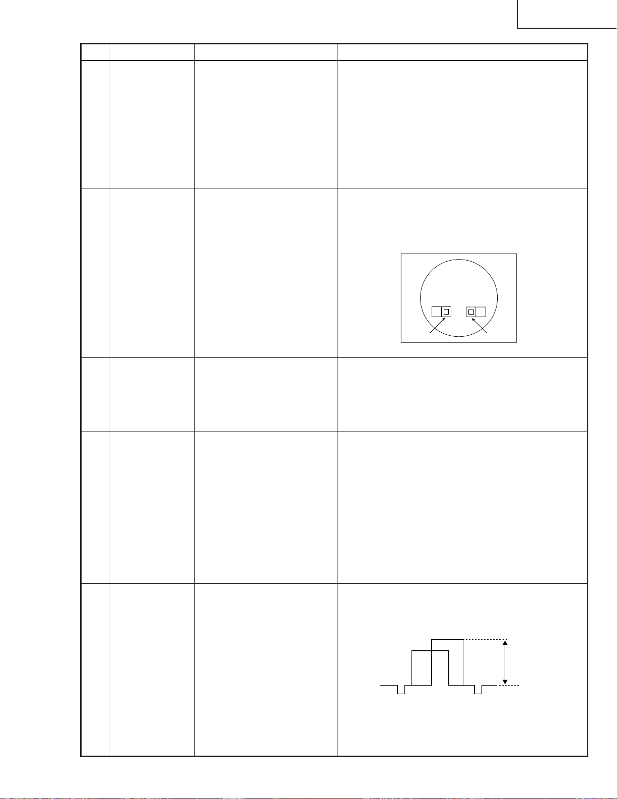
14 Horizontal
center
15 Video picture
adjustment
1. Feed the 32-step gray scale
signal (XGA).
Group : OUTPUT 1
Subject : R1-BLK (R)
B1-BLK (B)
1. Feed the NTSC monoscope
pattern signal.
2. Group : VIDEO 2
Subject : N358-DLY (4)
N443-DLY (0)
PAL-DLY (3)
SECAM-DLY (0)
Make sure the settings are
as above.
3. Group : VIDEO 1
Subject : NTSC-H
1. Feed the split colour bar signal.
Group : VIDEO 1
Subject : PICTURE
2. Connect the oscilloscope
between pin (2) of P801 and
GND.
» Choose the subjects R1-BLK and B1-BLK and
adjust the black balance of the gradation.
» Using the control switches or the remote controller
buttons, adjust the data to have the same
overscan.
» Using the control switches or the remote controller
buttons, adjust the black-to-white (100%) level
difference to 2.0 ±0.02 Vp-p.
2.0Vp-p
27
Page 28
XG-C40XU/XE
100% White Red
No. Adjusting point Adjusting conditions Adjusting procedure
16 Video
brightness
adjustment
1. Feed the baseband (split
colour bar) signal. (The ONAIR signal is not accepted
because of its too much
noise.)
Group : VIDEO 2
Subject :
VROS/VGOS/VBOS
2. Press the control switch or
the remote control’s mute
button (to set the gamma
correction to the process
setting).
17 Video AGC 1.
Feed the split colour bar signal.
Group : VIDEO 1
Subject : AGC
18 Tint 1. Feed the split colour bar
signal.
Group : VIDEO 1
Subject : TINT
2. Connect the oscilloscope to
pin (4) of P801.
» Using the control switches or the remote controller
buttons, adjust the setting until the black signal
becomes bit-less.
» Using the control switches or the remote controller
buttons, adjust the setting until the white signal
becomes bit-less.
» Using the control switches or the remote controller
buttons, adjust the data to have the -(B-Y) waveform downhill straight.
» After adjusting, adjust the
value of TINT up 3 point.
19 NTSC colour
saturation level
20 PAL colour
saturation level
21 SECAM colour
saturation level
1. Feed the split colour bar signal.
Group : VIDEO 1
Subject : N-COLOR
2. Connect the oscilloscope to
pin (1) of P801.
1. Feed the PAL colour bar signal.
Group : VIDEO 1
Subject : P-COLOR
2. Connect the oscilloscope to
pin (1) of P801.
1. Feed the SECAM colour bar
signal.
Group : VIDEO 1
Subject : S-COLOR
2. Connect the oscilloscope to
pin (1) of P801.
» Using the control switches or the remote controller
buttons, adjust the difference between the 100%
white portion and the red portion to 0.00 ±0.05 Vp-p.
(same as 100% white)
» Using the control switches or the remote controller
buttons, adjust the difference between the 100%
white portion and the red portion to 0.2 ±0.05 Vp-p.
100% White Red
» Using the control switches or the remote controller
buttons, adjust the data to have a level difference
of 0.2 ±0.05 Vp-p between the 100% white portion
and the red portion.
100% White Red
28
Page 29

No. Adjusting point Adjusting conditions Adjusting procedure
XG-C40XU/XE
22 Video input
panel signal
amplitude
adjustment
23 Video white
balance
24 DTV white
balance
1. Feed the NTSC 10-step signal.
2. Select the following group
and subject.
Group: VIDEO2
Subject: R1-GAIN
B1-GAIN
3. Connect the oscilloscope to
TP1 101 (R) and TP1201 (G).
4. For the blue colour, connect the oscilloscope to
TP1301 (B) and TP1201
(G).
1. Feed the NTSC monoscope
pattern signal
Group : VIDEO 2
Subject : R1-BLK
B1-BLK
1. Feed the monoscope pattern
signal.
2. Group: DTV
Subject: CR-OFFSET
CB-OFFSET
» Select R1-GAIN and adjust the setting so that the
R and G signals have the same amplitude.
» For the blue colour, adjust the setting the same
way.
» Using the control switches or the remote controller
buttons, adjust so that the entire screen looks
evenly colourless.
» Using the control switches or the remote controller
buttons, adjust so that the entire screen looks
evenly colourless.
25 Setup 1. Group: VIDEO1
Subject: SET UP B
SET UP C
26 Automatic
colour correction
27 Colour system
performance
check
28 Video system
performance
check
29 Audio system
performance
check
1. Using the colour correction
system (ccdc), apply automatic colour correction.
1. Receive the colour bar signal.
1. Receive the monoscope pattern signal.
» Make sure the settings are 11 for SET UP B and 2
for SET UP C.
» Make sure there is no noticeable colour irregularity
left on the screen.
» In the process mode and select L1. Check the col-
our and tint.
» In the process mode and select L2. Check the pic-
ture, brightness and sharpness.
» In the process mode nad select L3. Check the bass,
treble.
29
Page 30

XG-C40XU/XE
No. Adjusting point Adjusting conditions Adjusting procedure
30 RGB
performance
check
31 Off-timer
performance
check
32 Thermistor
performance
1. Receive the RGB signal. » In the process mode and select L4. Check the picture, brightness, red, blue, clock, phase, horizontal
position, and vertical position.
» In the process mode and select OFF. Make sure that
the off-timer starts with “5” (minutes), counts down each
minute in 1 second, and turns off the set at “0”.
1. Heat the thermistor using a
» Make sure the “TEMP” is displayed.
dryer.
check
33 Automatic
synchronization
1. Receive the PHASE check
pattern signal.
» Call the VGA/SVGA/XGA/SXGA mode and make
sure that the clock, phase, horizontal and vertical
positions can be automatically adjusted.
34 Keystone
» Make sure the keystone correction functions well.
correction
performance
check
35 Factory settings » Make the following settings.
Process
adjustment
S3 “Factory setting 3”(XG-C40XE)
S4 “Factory setting 4”(XG-C40XU)
Remote controller setting
30
Page 31

XG-C40XU/XE
ADJUSTING THE PC BOARD (CPCi-0047CE15/16. PC I/F Unit)
1. RGB level adjustment
1) Connect a signal generator to the projector that is equipped with the 0047 PWB. Set the signal generator
output to the XGA mode (VESA1024x768, 60Hz, 32-tone waveform). Adjust the output amplitude to 700
mVp-p at the P8404 connector.
2) Set the projector input to the RGB1 mode.
3) Using a pushbutton on the projector, call the process mode.
4) On the main menu screen, select the group “A/D”.
5) Select the subject “R-BRIGHT” in the group “A/D” and adjust the “R-BRIGHT” setting so that there should be
no bits around the screen.
6) Do the same with the “G-BRIGHT” and “B-BRIGHT” settings.
7) Next select the group “R-D” and the settings of the above subjects so that there should be no bits around the
screen.
8) Then select the groups “G-D” and “B-D” and make the same adjustments.
Now let’s go to the DTV level adjustment.
2. DTV level adjustment
1) Set the signal generator output to the green-only mode.
2) On the main menu screen of the process mode, select the group “DTV”.
3) Select the subject “G-BRIGHT” in the group “DTV” and adjust the “G-BRIGHT” setting so that there should be
no bits around the screen.
4) Do the same with the “CB-OFFSET” and “CR-OFFSET” settings.
Now the 0047 PWB on the projector is adjusted for delivery.
Note: There is no need to make the VIDEO input adjustments.
Servicing precautions
If the convergence gets out of spec in servicing the set, call the process mode and select the following group and
subjects.
Group: NOKO
Subject: R-CNV-H, R-CNV-V
G-CNV-H, G-CNV-V
B-CNV-H, B-CNV-V
(H and V are for horizontal and vertical adjustments, respectively.)
Adjust the above settings to the range of 0 to 4.
31
Page 32

XG-C40XU/XE
TROUBLE SHOOTING TABLE
Checking the PWB performance
Video input in trouble
Go to "Checking the video unit
circuit".
RGB input in trouble
Feed test pattern signal from
PC.
Is specified cable connected
between PC and projector?
Yes
Is supply voltage as specified?
Yes
Does image appear?
Yes
Go to "Trouble shooting table
for PC I/F unit ".
Through-output in trouble
Through-output circuit in
trouble.
No
Use specified cable.
No
Power circuit in trouble.
No
Check the connectors, starting
from the PC input circuit.
Remote control in trouble
Go to "Checking the remote
control".
32
Page 33

TROUBLE SHOOTING TABLE (Continued)
Checking the video system
XG-C40XU/XE
Is the lamp on?
Is specified voltage fed to EA
connectors?
Are there signal inputs at pins (3) and
(29) of P402?
Are there signal outputs at pins (3)
and (6) of IC816?
Yes
Go to "Checking IC801
(RGB signal output circuit)".
No
Yes
No
Yes
No
Yes
No
Check IC816, IC806 and
their peripheral circuits as
well as switching circuit.
Go to "Lamp fails to light-up".
Check the power circuit and its parts.
Are there signals at pin (4) of IC401
and pin (4) of IC402?
Yes
Check the video unit circuit
(IC6004 and its peripheral
circuits).
No
Check the oscillation circuit
of IC401 and IC402, and
their peripheral circuits.
Checking the video unit circuit
Is there video signal output at pin (7)
of IC6001?
Yes
Is there video signal input at IC6004?
Yes
Are there signal outputs at pins (6)
and (8) of IC6004?
Yes
Check the low-pass and buffer circuits
of Q6002 thru Q6008. Is the signal as
specified?
Yes
Go to "Checking IC801 (RGB signal
output circuit)".
No
Check the IC6001 selector switch,
terminal voltage and input circuit.
No
Check the low-pass and buffer
circuits of Q6009 thru Q6015.
No
Check IC6004 and its peripheral
circuits (bias).
No
Check Q6002 thru Q6008 and their
peripheral circuits.
33
Page 34

XG-C40XU/XE
TROUBLE SHOOTING TABLE (Continued)
Checking IC801 (RGB signal output circuit)
No
Are there RGB output waveforms at
pins (31), (32) and (33) of IC801?
Go to "No colour or unusual tone",
"No Y signal" or "Out of sync".
Are there output waveforms at the
emitters of Q1501, Q1502 and
Q1503?
Are there output waveforms at the
emitter of Q1505, Q1506 and Q1507?
Go to "Trouble shooting table for PC
I/F unit".
Yes
Yes
Yes
Checking the chroma and Y signals of IC801
No
Check the data transfer and other
performance at pins (17) and (18) of
video IC801.
No
Check Q1501 thru Q1503, SC1501
and their peripheral circuits.
No
Check IC1501, Q1505 thru Q1507
and their peripheral circuits.
(RGB signal output)
Are there signal inputs at pins (12)
(Y signal) and (19)(chroma signal) of
P402?
Yes
Are there output waveforms at pins
(3)(chroma signal) and (6)
(Y signal)of IC816?
Yes
Are there signal inputs at pins (20)
(chroma signal) and (21) (Y signal)
of IC801?
Yes
Go to "Checking IC801 (RGB
signal output circuit)".
No
Go to "Checking the video unit
circuit".
No
Check the IC816 switching and their
peripheral circuits. If there is no signal
at pins (9) and (1) of IC816, check 3-D
noise reduction circuit (IC806).
No
Check IC801 and its peripheral
circuits.
Check IC806 (3-D noise reduction
circuit) and its peripheral circuits.
34
Page 35

TROUBLE SHOOTING TABLE (Continued)
Checking IC806 (3-D noise reduction circuit)
and its peripheral circuits
XG-C40XU/XE
Are there signal inputs at pins (40)
(Y signal) and (45)(chroma signal) of
IC806?
Yes
Are there signal outputs at pins (55)
(Y signal) and (51)(chroma signal) of
IC806?
Yes
Are there signal outputs at the
emitters of Q817 (Y signal) and Q910
(chroma signal)?
Yes
Check IC816 and IC801 (RGB signal
output circuit).
No
Check the buffer circuit of Q814 thru
Q816 as well as Q903 thru Q906.
No
Check IC806, IC807 (memory) and
their peripheral circuits.
No
Check the low-pass circuit around
Q817, Q907 and Q910.
No colour or unusual tone (NTSC, PAL)
Is there chroma signal input at pin
(20) of IC801?
Yes
Are there signal outputs at pins
(46)(R-Y) and (45)(B-Y) of IC801?
Yes
No
Go back to the signal processing
block.
No
Check the oscillation of X801 and
X802, and their peripheral circuits.
Check IC803, IC814 and their
peripheral circuits.
35
Page 36

XG-C40XU/XE
TROUBLE SHOOTING TABLE (Continued)
No or unusual Y signal
Is there Y signal input at pin (21) of
IC801?
Yes
Is there Y signal output at pin (40) of
IC801?
Yes
Is there Y signal output at pin (17) of
IC803?
Yes
Check IC803 and its peripheral
circuits.
No
Go back to the signal processing
block.
No
Check IC801 and its peripheral
circuits.
No
Check IC803 and its peripheral
circuits as well as IC805 (AGC).
No or unusual horizontal sync
Is there horizontal sync pulse output
at pin (56) of IC801?
Yes
Is there horizontal sync pulse output
at pin (9) of IC603?
Yes
No
Check IC801 and its peripheral
circuits.
No
Check the pulse shaping circuit of
IC602 and IC603.
Check IC604 and its peripheral
circuits, and go to "Trouble shooting
table for PC I/F unit".
No or unusual vertical sync
Is there vertical sync pulse output at
pin (4) of IC801?
Yes
Check IC604 and its peripheral
circuits, and go to "Trouble shooting
table for PC I/F unit".
No
Check IC801 and its peripheral
circuits.
36
Page 37

TROUBLE SHOOTING TABLE (Continued)
Checking the output PWB unit
XG-C40XU/XE
If there is no signal at SC1501
and SC1502, go to the video
system block.
If there is no signal at SC1404
and SC1405, go to "Trouble
shooting table for PC I/F unit".
Are there signal inputs at
SC1404, SC1405, SC1501 and
SC1502?
Are voltages applied to EA
connectors and SC5502?
Yes
Are there signal outputs at
pins (14) ,(16) and (18) of
IC1401 ?
Yes
Are there signal inputs at pin
(47) of IC1101, IC1201 and
IC1301?
Yes
Are there signal outputs at pins
(17), (19), (21), (28), (30) and
(32) of IC1101, IC1201 and
IC1301?
Yes
NoNo
If there is no signal at EA
connector or SC5502, go to
Checking the power unitblock.
No
Check IC1401 and their
peripheral circuits.
No
Check IC1401 and their
peripheral circuits.
No
Check IC1101,IC1201,IC1301
and their peripheral circuits.
If there is no signal input at
pins (1) and (31) of SC1101,
SC1102 and SC1103, check
the switching circuit and
amplifier circuit of IC1101,
IC1201, IC1301, IC1102,
IC1202, IC1302 and their
peripheral circuits.
Are there signal outputs at pins
(17), (19), (21), (28), (30) and
(32) of IC1102, IC1202 and
IC1302?
No
Are there signal inputs at
SC1101, SC1201 and
SC1301?
Check the R, G and B panels.
Yes
Yes
Yes
No
Check IC1102,IC1202,IC1302
and their peripheral circuits.
No
If there is no signal input at
pins (15) and (30) of
SC1101, SC1102 and
SC1103, check IC1409
and their peripheral
circuits.
Check IC1106, IC1206,
IC1306, IC1408 and their
peripheral circuits.
37
Page 38

XG-C40XU/XE
TROUBLE SHOOTING TABLE (Continued)
No audio output
Are there audio signal inputs at pin
(2) of IC1411?
Are there audio signal outputs at pin
(2) of P5508?
Are there audio signal outputs at pin
(6) of IC7301?
If the voltage at pin (2) of IC7301 is
not as specified, check Q5501,
Q5502 and their peripheral circuits.
No
Yes
No
Yes
No
Yes
Check IC7301 and its peripheral
circuits, and the SP connectors and
speakers.
Checkig the Power Unit
Check the input, the switching circuit
of IC3303 and IC3304, and their
peripheral circuit,SC3001,SC1502,etc.
Check the IC1411 control voltage,and
its peripheral circuits.
Check IC7301 and its peripheral
circuits.
Which output voltage line fails?
6.7V
Replace ICP751.
Replace TF701.
There is no voltage output at
EA connector.
Yes
Is there any other output
voltage failure?
Is EA connector disconnected
or loose?
Is AC voltage (85-264V)
applied across the PA
connector?
Yes
Is TF701 open?
Is R706 open?
Yes
No
No
Yes
No
Yes
Reconnect the EA connector.
No
Replace F701 or Check
Bimetal SW.
No
Replace R700. Replace Power
unit.
38
Page 39

TROUBLE SHOOTING TABLE (Continued)
Power on
XG-C40XU/XE
Is the right input selected?
Yes
Are the PC, video and LCP cables as
specified and properly connected?
Yes
With the contrast control at maximum,
does the image appear?
No
Is the voltage at CON3 (P8502)
connector as specified?
Yes
Hook up a personal computer.
Does the image appear?
No
Select the right input with remote
control.
No
Use the right cables or reconnect the
cables.
Yes
Readjust the video system.
No
Power circuit faulty.
No
Yes
Is the image as specified?
Yes
A
Is the image's colour as specified?
Yes
Does the on-screen display function?
Yes
Does the remote control function?
Yes
End
Go to "Checking the clock circuit and
its peripheral circuits".
No
Check the sync signal circuit and its
peripheral circuits.
No
Check the video circuit and its
peripheral circuits.
No
Go to "Checking the OSD circuit and
its peripheral circuits".
No
Go to "Checking the remote control".
39
Page 40

XG-C40XU/XE
Reconnect the
lamp into socket.
TROUBLE SHOOTING TABLE (Continued)
Is the lamp out of socket?
Yes
Replace the
lamp.
No
Lamp fails to light-up
Turn on the power switch. Is
Yes
discharging sound heard from
the lamp?
No
Is the ballast cooling fan
running?
Yes
No
Check the power circuit.
Replace the ballast.
Is DC 360V voltage applied
between PL connector pins?
Yes
Is 2V or higher voltage applied
between pins (1) and (2) of
ballast's D connector?
Is D connector disconnected?
Yes
Reconnect the
connector into socket.
No
Yes
No
No
Check the
microcomputer circuit.
40
Page 41

TROUBLE SHOOTING TABLE FOR PC I/F UNIT-1
Power On
XG-C40XU/XE
Is the input properly selected?
Yes
Are the PC, video and projector
cables as specified and properly
connected?
Yes
Turn up the contrast control all the
way. Is the image visible?
No
Is the voltage at connector P8502 as
specified?
Yes
Is the image invisible?
No
Is the image distorted?
No
Are the image colors abnormal?
No
No
Yes
No
Yes
Yes
Yes
Select the specified input with the
remote controller.
Use the specified cables. Reconnect
them correctly.
Readjust the video settings.
Power circuit defective.
Go to “Checking the Clock Circuit
and its Peripheral Circuits”.
Go to “Checking the Sync Signal
Circuit and its Peripheral Circuits”.
Go to “Checking the Video Circuit
and its Peripheral Circuits”.
4
No
Does the onscreen display
malfunction?
No
Does the remote controller
malfunction?
No
End
Yes
Yes
Go to “Checking the OSD Circuit and
its Peripheral Circuits”.
Go to “Checking the Remote
Controller”.
41
Page 42

XG-C40XU/XE
TROUBLE SHOOTING TABLE FOR PC I/F UNIT-2
Checking the clock circuit and its peripheral circuits
Is X8001 (6MHz) oscillating?
Yes
Is X8003 (1.84MHz) oscillating?
Yes
Is X8004 (22.165MHz) oscillating?
Yes
Is X8005 (18.75MHz) oscillating?
Yes
Does pin (162) of IC8001 function?
Yes
No
No
No
No
No
X8001 or its peripheral part faulty.
X8003 or its peripheral part faulty.
X8004 or its peripheral part faulty.
X8005 or its peripheral part faulty.
IC8001 or its peripheral circuit faulty.
5
TROUBLE SHOOTING TABLE FOR PC I/F UNIT-3
Checking the Sync Signal Circuit and its Peripheral Circuits
5
No
Is the sync signal of split type?
Yes
Are there signals at TP8004 and
TP8005?
Yes
No
IC8610 or terminal PWB defective.
No
Is the sync signal of Sync On Green
type?
Yes
Are there signals at pin (7) of IC8611?
Yes
Are there signals at pins (149) (TL80
34) and (150) (TL8035) of IC8020?
Yes
No
Does the input have a resolution lower
than XGA or is it video input?
Yes
Are there signals at pins (26) (TL8043),
(28) (TL8041) and (29) (TL8042) of
IC8020?
Yes
Are there signals at pins (13) thru
(52), except for GND, of P8405?
Yes
6
No
No
No
No
IC8611 or its peripheral part faulty.
IC8025 or its peripheral part faulty.
IC8020 or its peripheral part faulty.
IC8029,IC8609 or its peripheral
part faulty.
42
Page 43

TROUBLE SHOOTING TABLE FOR PC I/F UNIT-4
Checking the PLL circuit and its peripheral circuits
6
XG-C40XU/XE
Are there signal at pins (111) and
(112) of IC8606?
Yes
Are there signals at pins (7) and
(10) of IC8601?
Yes
Check the video circuit and its
peripheral circuits.
Is image as specified at resolution
above XGA level?
Yes
Is image as specified at resolution
below XGA level?
Yes
No
IC8025,IC8600 or its peripheral
circuit faulty.
No
IC8601,IC8606 or its peripheral
circuit faulty.
No
Check the S-XGA video circuit and
its peripheral circuits.
No
Check the VGA video circuit and its
peripheral circuits.
Hook up a video system. Is the
display as specified?
Yes
4
No
Check the video system's video
circuit and its peripheral circuits.
43
Page 44

XG-C40XU/XE
TROUBLE SHOOTING TABLE FOR PC I/F UNIT-5
Checking the SXGA's red video
circuit and its
peripheral circuits
Is there signal at pin (139) of IC8606?
Yes
Are there signals at pins (21) thru (31)
as well as (34) thru (41), except for
GND, of P8606?
Yes
Are there signals at TL8044 and
TL8046?
Yes
No No
Terminal PWB,C8616 defective.
No No
IC8606 or its peripheral circuit faulty.
No No
IC8025 or its peripheral circuit faulty.
No
IC8020 or its peripheral circuit faulty.
Checking the VGA's
red video circuit and
its peripheral
circuits
Is there signal at pin (139) of IC8606?
Yes
Are there signals at pins (21) thru (31)
as well as (34) thru (41), except for
GND, of P8606?
Yes
Are there signals at pins (112) thru
(119) of IC8020?
Yes
Are there signals at pins (69) thru (73)
and (189) thru (192) of IC8020?
Yes
1
Is there signal at pin (Y11)(TL8612) of
IC8609?
Yes
Are there signals at pins (1) thru
(10) of IC8051?
Yes
IC8051 or its peripheral circuit or output
PWB faulty.
No
IC8029 or its peripheral circuit faulty.
No
IC8609 or its peripheral circuit faulty.
C8702 or its peripheral circuit or signal
PWB faulty.
Check the video
system's red video
circuit and its
peripheral circuits
No
Is there signal at pin (144) of IC8606?
Yes
1
44
Page 45

TROUBLE SHOOTING TABLE FOR PC I/F UNIT-6
XG-C40XU/XE
Checking the SXGA's green video
circuit and its
peripheral circuits
Is there signal at pin (124) of IC8606?
Yes
Are there signals at pins (68) thru (75)
as well as (78) thru (88), except for
GND, of P8606?
Yes
Are there signals at TL8045 and
TL8047?
Yes
No No
Terminal PWB, C8620 defective.
No No
IC8606 or its peripheral circuit faulty.
No No
IC8025 or its peripheral circuit faulty.
No
IC8020 or its peripheral circuit faulty.
Checking the VGA's
green video circuit
and its peripheral
circuits
Is there signal at pin (124) of IC8606?
Yes
Are there signals at pins (68) thru (75)
as well as (78) thru (88), except for
GND, of P8606?
Yes
Are there signals at pins (165) thru
(177) of IC8020?
Yes
Are there signals at pins (178) thru (187)
of IC8020?
Yes
1
Is there signal at pin (V13)(TL8613) of
IC8609?
Yes
Are there signals at pins (11) thru
(20) of IC8051?
Yes
IC8051 or its peripheral circuit or output
PWB faulty.
No
IC8029 or its peripheral circuit faulty.
No
IC8609 or its peripheral circuit faulty.
C8703 or its peripheral circuit or signal
PWB faulty.
Check the video
system's green
video circuit and its
peripheral circuits
No
Is there signal at pin (126) of IC8606?
Yes
1
45
Page 46

XG-C40XU/XE
TROUBLE SHOOTING TABLE FOR PC I/F UNIT-7
Checking the SXGA's blue video
circuit and its
peripheral circuits
Is there signal at pin (133) of IC8606?
Yes
Are there signals at pins (45) thru (53)
as well as (56) thru (64), except for
GND, of P8606?
Yes
Are there signals at TL8048 and
TL8049?
Yes
No No
Terminal PWB, C8623 defective.
No No
IC8606 or its peripheral circuit faulty.
No No
IC8025 or its peripheral circuit faulty.
No
IC8020 or its peripheral circuit faulty.
Checking the VGA's
blue video circuit
and its peripheral
circuits
Is there signal at pin (133) of IC8606?
Yes
Are there signals at pins (45) thru (53)
as well as (56) thru (64), except for
GND, of P8606?
Yes
1
Are there signals at pins (85) thru
(93) of IC8020?
Yes
Are there signals at pins (74) thru (83)
of IC8020?
Yes
Is there signal at pin (U15)(TL8614) of
IC8609?
Yes
Are there signals at pins (21) thru
(30) of IC8051?
Yes
IC8051 or its peripheral circuit or output
PWB faulty.
No
IC8029 or its peripheral circuit faulty.
No
IC8609 or its peripheral circuit faulty.
C8704 or its peripheral circuit or signal
PWB faulty.
Check the video
system's blue video
circuit and its
peripheral circuits
No
Is there signal at pin (136) of IC8606?
Yes
1
46
Page 47

TROUBLE SHOOTING TABLE FOR PC I/F UNIT-8
Checking the OSD circuit and its peripheral circuits
Display OSD on the screen.
XG-C40XU/XE
Are there signals at pins (56), (58),
(71) and (72) (TL8054,TL8053,TL8052,
TL8051) of IC8048?
Yes
Are there signals at pins (12), (14)
thru (17) and (20) of IC8046?
Yes
Are there signals at pins (23) thru
(42) of IC8046?
Yes
IC8048 or its peripheral circuit faulty.
No
IC8029 or its peripheral circuit faulty.
No
IC8048 or its peripheral circuit faulty.
No
IC8046 or its peripheral circuit faulty.
Checking the remote controllor
Use the remote controller. Is there the
signal at pin (59) of P8405?
Yes
IC8001 circuit faulty.
No
Output PWB faulty.
47
Page 48

XG-C40XU/XE
Technische Daten
Produkttyp
Modell
Videosystem
Wiedergabeverfahren
LCD-Projektionspaneel
Objektiv
Projektionslampe
Kontrastverhältnis
Videoeingangssignal
S-Videoeingangssignal
Horizontale Auflösung
Audioausgang
RGB-Computereingangssignal
Punktetakt
Vertikale Frequenz
Horizontale Frequenz
Computereingangs-Signal
Lautsprechersystem
Nennspannung
Eingangsspannung
Nennfrequenz
Nennaufnahme
Betriebstemperatur
Lagertemperatur
Gehäuse
I/R-Trägerfrequenz
Laserzeiger der Fernbedienung
Abmessungen (ca.)
Gewicht (ca.)
Mitgeliefertes Zubehör
Ersatzteile
LCD Projector
XG-C40XE
PAL/SECAM/NTSC 3.58/NTSC 4.43/DTV 480P/DTV 720P/DTV 1080I
LCD-Projektionspaneel × 3, optisches RGB-Verschlußverfahren
Panelgröße: 22,9 mm (0,9) (13,9 mm [H] × 18,5 mm [B])
Wiedergabe-Verfahren: Durchlässiges TN-Flüssigkristall-Paneel
Treiberverfahren: TFT (Dünnfilmtransistor) Aktivmatrix-Paneel
Anzahl der Bildpunkte: 786.432 Bildpunkte (1.024 [H] × 768 [V])
1–1,3 Zoomobjektiv, F1,7–2,0, f = 33–43 mm
200 W Gleichstrom-Lampe
250:1
RCA-Stecker: VIDEO, Gemischtes Video, 1,0 Vs-s, negatives Sync.-Signal, 75 Ω
terminiert
RCA-Stecker: AUDIO, 0,5 Vrms mehr als 22 kΩ (Stereo)
4-Pin Mini DIN-Stecker
Y (Luminanz-Signal): 1,0 Vs-s, negatives Sync.-Signal, 75 Ω terminiert
C (Chrominanz-Signal): Stoß 0,286 Vs-s, 75 Ω terminiert
560 Fernsehzeilen (Videoeingang), 750 Fernsehzeilen (DTV 720P-Eingang, Punkt für
Punkt)
3 W (monaural)
IN MINI
15-P
D-SUB S
TECKANSCHLUSS
(INPUT 1, 2):
RGB getrennt/gemischte Sync./Sync. auf Grün-Typ analoger Eingang: 0–0,7 Vs-s,
positiv, 75 Ω terminiert
TEREO-MINIBUCHSE
S
ORIZONTALES SYNC
H
: AUDIO, 0,5 Vrms, mehr als 22 kΩ (Stereo)
.-S
IGNAL
: TTL-Pegelsignal (positiv/negativ) oder gemischtes Sync.-
Signal (nur Macintosh)
V
ERTIKALES SYNC
.-S
IGNAL
: Wie oben
12–230 MHz
43–200 Hz
15–126 kHz
9-Pin Mini DIN-Steckanschluß (RS-232C-Eingangsanschluß)
8 cm (3
3
⁄32) rund
AC 100–240 V
3,3 A
50/60 Hz
300 W
+ 5°C bis + 40°C
– 20°C bis + 60°C
Kunststoff
38 kHz
Wellenlänge: 650 nm / Max. Ausgang: 1 mW / Klasse II Lasergerät
229 × 121 × 310 mm (B × H × T) (nur Hauptgerät)
243,5 × 134 × 358,4 mm (B × H × T) (einschließlich Drehfüße und vorstehende Teile)
4,8 kg
Fernbedienung, Zwei Batterien der Größe AA, Netzkabel (1,8 m), RGBComputerkabel (3m), Computer-Audiokabel (3 m), USB-Maus-Steuerungskabel (1,5 m),
DIN-D-Sub RS-232C-Kabel (15 cm),Fernbedienungs-Mausempfänger, Ersatz-Luftfilter,
Objektivkappe (angebracht), CD-ROM, Bedienungsanleitung für LCD-Projektor,
Kurzreferenz für LCD-Projektor,Software-Anleitung für Sharp Advanced Presentation
Lampensatz (Lampe/Käfigmodul) (BQC-XGC40XU/1), Fernbedienung
(RRMCG1584CESA), Batterien der Größe AA, Netzkabel (QACCB5024CENA,
QACCV4002CEZZ), RGB-Computerkabel(QCNWG0002CEZZ), Computer-Audiokabel
(QCNW-4870CEZZ),USB-Maus-Steuerungskabel (QCNWG0007CEPZ), DIN-D-Sub
RS-232C-Kabel (QCNW-5288CEZZ), Fernbedienungs-Mausempfänger (RUNTK0673
CEZZ), Luftfilter (PFILD0076CEZZ), Objektivkappe(GCOVH1307CESB), CD-ROM
(UDSKA0057CEN1), Bedienungsanleitung für LCD-Projektor (TINS-7533CEZZ),
Kurzreferenz für LCD-Projektor (TINS-7534CEZZ, TINS-7535CEZZ, TINS-7536CEZZ),
Software-Anleitung für Sharp Advanced Presentation(TINS-7537CEZZ)
Dieser Projektor von SHARP ist mit 3 LCD- (Flüssigkristallanzeige)
Projektionspaneels ausgestattet. Diese neuartigen Projektionspaneels
enthalten TFTs (Dünnfilmtransistoren) mit insgesamt 786.432
Bildpunkten (× RGB). Bei allen technologisch fortschrittlichen,
elektronischen Geräten, z. B. Großbild-Fernsehern, Videosystemen
bzw. Videokameras, sind bestimmte Toleranzgrenzen für die
Funktionen gegeben.
Änderungen der technischen Daten ohne vorherige Ankündigung vorbehalten.
Dieses Gerät hat einige inaktive, innerhalb akzeptierter
Toleranzgrenzen liegende TFTs, die als beleuchtete oder als nicht
aktive Punkte auf der Bildwand wiedergegeben werden. Dies hat
keinen Einfluß auf die Bildqualität und die Lebensdauer des Gerätes.
48
Page 49

4
4
4
4
HINWEIS FÜR DAS WARTUNGSPERSONAL
23456789012345678901234567890121234567890123
23456789012345678901234567890121234567890123
ACHTUNG: UV-STRAHLUNG
23456789012345678901234567890121234567890123
23456789012345678901234567890121234567890123
Die Lichtquelle im LCD-Projektor, eine MetallHalogen-Lampe, gibt eine geringe UV-Strahlung ab.
DIREKTE BESTRAHLUNG AUF AUGEN
UND HAUT MUSS VERMIEDEN WERDEN.
Zur Gewährleistung der Sicherheit muß folgendes
beachtet werden:
1. Bei Arbeiten am Projektor bei eingeschalteter
Lampe und abgenommenem oberen Gehäuse
muß unbedingt eine Sonnenbrille getragen
werden.
XG-C40XU/XE
ËAuswechseln der Lampe
Hinweis:
Da die Lampe während des Betriebs sehr heiß wird,
sollte die Lampe erst ausgewechselt werden, nachdem
das Gerät mindestens eine Stunde ausgeschaltet war ,
damit die Lampe ausreichend abkühlen kann.
Beim Installieren der neuen Lampe muß darauf
geachtet werden, die Lampe selbst (Glaskolben)
nicht zu berühren. Vielmehr muß die Lampe am
Reflektor 2 gehalten werden.
[Es darf nur ein Original-Ersatzteil verwendet
werden.]
Lampe
1
2
Reflektor
2. Die Lampe darf nicht außerhalb des
Lampengehäuses eingeschaltet werden.
3. Betrieb für länger als 2 Stunden bei
abgenommenem Gehäuse ist nicht zulässig.
Zur Beachtung bei UV-Strahlung
und Mitteldruck-Lampen
1. Vor dem Auswechseln der Lampe muß der
Netzstecker gezogen werden.
2. Vor Durchführung von Wartungsarbeiten muß das
Gerät eine Stunde abkühlen.
3. Nur mit dem gleichen Lampentyp ersetzen Typ
CLMPF0075CE01 oder BQC-XGC40XU/1;
Nennleistung 85 V / 200 W.
4. Die Lampe gibt eine geringe UV-Strahlung ab,
daher muß direkter Augenkontakt vermieden
werden.
5. Die Mitteldruck-Lampe weist ein Explosionsrisiko
auf. Daher müssen die nachstehenden
Installationsanweisungen beachtet werden, und
die Lampe muß vorsichtig behandelt werden.
GEFAHR! — Niemals die Spannungsversorgung
einschalten, ohne daß eine Lampe vorhanden ist,
um elektrische Schläge und Schäden am Gerät zu
vermeiden, da der Stabilisator anfangs hohe
Spannungen erzeugt.
Da eine geringe UV-Strahlung aus einer Öffnung
zwischen der Schachtabdeckung und dem
Lampengehäuse austritt, sollte der Objektivdeckel
bei Wartungsarbeiten auf die Öffnung gesetzt
werden, um die Bestrahlung von Augen und Haut
zu vermeiden (Abb. 1).
Hinweis: Besorgen Sie sich einen Objektivdeckel,
bevor Sie Arbeiten an einem Modell XGC40XE durchführen, das keinen
Objektivdeckel aufweist.
Objectivdeckel
SHARP
Abbildung 1.
49
Page 50

XG-C40XU/XE
BEDIENUNGSANLEITUNG
Lage der Bedienelemente
Projektor
Stummschaltungs-Taste
(MUTE)
Lampenaustausch-Anzeige
Betriebsanzeige
Netz-Tasten (ON/OFF)
Trapezverzeichnungs-Taste
(KEYSTONE)
Eingangs-Taste (INPUT)
Standbild-Taste (FREEZE)
Vergrößern-Taste (ENLARGE)
Schwarzbild-Taste
(BLACK SCREEN)
Einstellungs-Tasten
('/"/\/|)
Zoom-Knopf
Fernbedienungs-Sensor
Fokussier-Knopf
Ansicht von vorne und oben
Temperaturwarnanzeige
Lautstärke-Tasten
(VOLUME + / – )
Menü-Taste (MENU)
Auto-Synchron-Taste
(AUTO SYNC)
Größe-Taste (RESIZE)
GAMMA-Taste
Storno-Taste (UNDO)
Eingabe-Taste (ENTER)
Tragegriff
Standardanschluß für
Kensington-Sicherheitssperre
Drehfuß-Feststeller
Seiten- und Rückansicht
Kühlventilator (Luftauslaß)
Eingangs-Port 1 (HD 15)
(INPUT 1)
RS-232C-Anschlußstelle
(9-Pin Mini DIN)
Ausangs-Port für Eingangs-Port 1, 2
(HD 15) (OUTPUT-Port für INPUT 1, 2)
Audioeingangsanschlüsse 3
(RCA) (AUDIO INPUT 3)
Steckanschluß
Lautsprecher
Luftfilter/Kühlventilator
(Lufteinlaß)
Fernbedienungs-Sensor
Eingangs-Port 2 (HD 15)
(INPUT 2)
Audioausgangsanschluß
(3,5 mm Stereo-Minibuchse)
(AUDIO OUTPUT)
Audioeingangsanschluß für EingangsPort 1, 2 (3,5 mm Stereo-Minibuchse)
(AUDIO INPUT für INPUT 1, 2)
S-Videoeingangsanschluß 4
(4-Pin Mini DIN)
(S-VIDEO INPUT)
Videoeinganganschluß 3
(RCA) (VIDEO INPUT 3)
50
Page 51

Betrieb mit der drahtlosen Maus-Fernbedienung
Fernbedienung
XG-C40XU/XE
Vorderansicht
Stummschaltungs-
Taste (MUTE)
Netz-Tasten
(ON/OFF)
Trapezverzeichnungs-/
Schwarzbild-Taste
(KEYSTONE/BLACK
SCREEN)
Rechte Klick-/
Eingabe-Taste
(R-CLICK/ENTER)
Eingangs-Taste
(INPUT)
Standbild-Taste
(FREEZE)
Vergrößern-Taste
(ENLARGE)
Hilfsmittel-Taste
(TOOLS)
Maus-/Einstellungs-
Schalter
(MOUSE/ADJ.)
Lautstärke-Tasten
( + / – )
Laserzeiger-/MenüTaste
(LASER/MENU)
Maus-/EinstellungsTasten ('/"/\/|)
Storno-Taste (UNDO)
Auto-Synchron-Taste
(AUTO SYNC)
Größe-Taste
(RESIZE)
GAMMA-Taste
Beleuchtungs-Taste
(LIGHT)
Ansicht von hinten
Linke Klick-Taste
(L-CLICK)
Ansicht von oben
Einsetzen der Batterien
Zum Entfernen der
1
Batteriefachabdeckung
auf die Pfeilmarkierung
drücken und in
Pfeilrichtung schieben.
Batteriefach-
abdeckung
Zwei Batterien der Größe
2
AA einlegen und
sicherstellen, daß die
Pole mit der + und –
Markierung im
Batteriefach
übereinstimmen.
Batteriefach
ÜbertragungsAnzeige
Laserlichtfenster
Die seitlichen Vorsprünge
3
der Batteriefachabdeckung
in die entsprechenden
Schlitze einsetzen und auf
die Abdeckung drücken,
bis sie richtig
aufgeschoben ist.
Batteriefach-
abdeckung
51
Page 52

XG-C40XU/XE
Verwendung der Fernbedienung als eine drahtlose Maus
Die Fernbedienung ist mit den folgenden drei
Funktionen ausgestattet:
MOUSE/ADJ.-Schalter
(Fernbedienung)
• Projektor-Steuerung
• Drahtlose Maus
MOUSE
ADJ.
MOUSE
ADJ.
• Laserzeiger
Drahtlose Maus
Laserzeiger
Projektor-
Steuerung
Positionierung der Fernbedienung bzw. des Mausempfängers
• Die Fernbedienung kann zur Steuerung des Projektors innerhalb des unten gezeigten Bereiches verwendet
werden.
• Der Fernbedienungs-Mausempfänger kann mit der Fernbedienung zusammen zur Steuerung der Mausfunktion
eines angeschlossenen Computers innerhalb des unten gezeigten Bereiches verwendet werden.
• Das Signal der Fernbedienung kann für einen einfacheren Betrieb von der Bildwand reflektiert werden. Der wirksame
Abstand des Signals kann aufgrund des Materials der Bildwand unterschiedlich sein.
Steuerung des Projektors
7 m
30˚
Verwendung der drahtlosen Maus
FernbedienungFernbedienung
30˚
45˚
30˚
4 m
45˚
30˚
Fernbedienung
30˚
120˚
FernbedienungsMausempfänger
52
Page 53

XG-C40XU/XE
Verwendbare Tasten in der MOUSE-Betriebsart
Fernbedienung
(Ansicht von vorne)
LASER
BLACK SCREEN
Maus
R-CLICK
LIGHT
Fernbedienung
(Ansicht der Rückseite)
L-CLICK
Verwendung als eine drahtlose Maus
Sicherstellen, daß der mitgelieferte FernbedienungsMausempfänger am Computer angeschlossen ist.
(Den MOUSE/ADJ.-Schalter auf der
Fernbedienung auf die MOUSE-Position
schieben.)
• Die drahtlose Maus kann nicht richtig funktionieren, wenn
der serielle Port des Computers nicht richtig eingestellt ist.
Siehe die Bedienungsanleitung des Computers für Hinweise
zur Einstellung bzw. Installation des Maustreibers.
• Für eintastige Systeme kann sowohl L-CLICK als auch R-
CLICK verwendet werden.
Verwendung der Fernbedienung in einem dunklen
Raum
Durch Drücken von LIGHT werden die Tasten
beleuchtet. Die grünen Tasten bedeuten Mausbetrieb
und die roten Tasten Projektoreinstellungen.
Tastenbezeichnung
LASER/MENU
BLACK SCREEN/KEYSTONE
R-CLICK/ENTER
'/"/\/|
L-CLICK
ON/OFF
VOLUME + / –
MUTE
INPUT
UNDO
FREEZE
AUTO SYNC
ENLARGE
RESIZE
TOOLS
GAMMA
Position des MOUSE/ADJ.-Schalters
MOUSE
LASER (GRÜN)
BLACK SCREEN (GRÜN)
R-CLICK (GRÜN)
'/"/\/|
JA (LEUCHTET NICHT)
(LEUCHTET NICHT)
MENU (ROT)
KEYSTONE (ROT)
ENTER (ROT)
'/"/\/|
JA (ROT)
MOUSE
ADJ.
ADJ.
(LEUCHTET NICHT)
—
Verwendung als ein Laserzeiger
(Den MOUSE/ADJ.-Schalter auf der
Fernbedienung auf die MOUSE-Position
schieben.)
LASER ( ) zum Aktivieren des Laserzeigers drücken.
Beim Loslassen der Taste erlöscht das Licht
automatisch.
• Aus Sicherheitsgründen erlöscht der Laserzeiger
automatisch nach einer Minute fortlaufender Verwendung.
Zum Einschalten LASER ( ) loslassen und erneut drücken.
53
MOUSE
ADJ.
Page 54

XG-C40XU/XE
Pinbelegung
Analoger Computer-Signaleingang 1 und 2: 15-Pin Mini-D-Sub-Buchse
Computereingang
Analog
1. Videoeingang (rot)
2. Videoeingang
(Grün/Sync. auf Grün)
3. Videoeingang (blau)
4. Reserveeingang 1
5. Gemischtes Sync.-Signal
6. Erdung (rot)
7. Erdung (Grün/Sync. auf Grün)
8. Erdung (blau)
Komponenten-Eingang
1. P
R(CR
)
2. Y
3. P
B
4. Nicht belegt
5. Nicht belegt
6. Erdung (P
7. Erdung (Y)
8. Erdung (P
R
)
B
)
10
15
5
1
6
11
9. Nicht belegt
10. MASSE
11. MASSE
12. Bi-direktionale Daten
13. Horizontales Sync.Signal
14. Vertikales Sync.-Signal
15. Daten-Zeitgeber
9. Nicht belegt
10. Nicht belegt
11. Nicht belegt
12. Nicht belegt
13. Nicht belegt
14. Nicht belegt
15. Nicht belegt
RS-232C-Anschlußstelle: 9-Pin D-Sub-Stecker des DIN-D-Sub RS-232C-Kabels
Pin Nr. Signal Name E/A Referenz
1
5
9
6
1 CD Nicht angeschlossen
2 RD Daten empfangen Eingang
3 SD Daten senden
4 ER Nicht angeschlossen
5 SG Signalerdung
6 DR Datensatz bereit
7RS
8 CS Bereit zum Senden Eingang
9 CI Nicht angeschlossen
Anforderung zum Senden
Ausgang
Ausgang
Ausgang
An internen Schaltkreis angeschlossen
An internen Schaltkreis angeschlossen
An internen Schaltkreis angeschlossen
Nicht angeschlossen
An internen Schaltkreis angeschlossen
An internen Schaltkreis angeschlossen
RS-232C-Anschlußstelle: 9-Pin Mini DIN-Steckanschluß
8
9
7
6
5
2
4
1
Pin Nr. Signal Name E/A Referenz
1 VCC + 3,3 V (Reserviert)
2 RD Daten empfangen Eingang
3 SD Daten senden
4 EXIR
3
5 SG Signalerdung
6 ERX
7RS
8 CS Bereit zum Senden Eingang
9 ETX IR-Signalübertragung
Detektor für Zusatzgerät
(Reserviert)
IR Empfangssignal von
IR-Verstärker (Reserviert)
Aufforderung zum Senden
(Reserviert)
Ausgang
Ausgang
Eingang Nicht angeschlossen
Eingang Nicht angeschlossen
Ausgang
Ausgang
Nicht angeschlossen
An internen Schaltkreis angeschlossen
An internen Schaltkreis angeschlossen
An internen Schaltkreis angeschlossen
An internen Schaltkreis angeschlossen
An internen Schaltkreis angeschlossen
Nicht angeschlossen
54
Page 55

XG-C40XU/XE
Abmessungen
(124,5)
64
/
1
(138,5) 49
64
/
33
54
Ansicht der Rückseite
Ansicht von oben
53
/64 (97,5)
3
(33,5)
16
/
5
1
(237,5)
32
/
11
9
25
/64 (10)
(27,5)
64
/
5
1
(61)5
32
/
13
2
(142)
32
/
19
(61)4
32
/
13
2
(23)
32
/
29
13
(310)5
64
/
12
(358,4)
64
/
7
14
3 51/64 (96,5)
23
/64 (9)
23
/64 (9)
(262)
16
/
5
10
Seitenansicht
(83)
64
/
17
3
(93)
32
/
21
3
(30)
16
/
13
1
63
/64 (25)
w
9 19/32 (243,5)
1
/64 (229)
9
7
/16 (11)
11
1
Ansicht von vorne
13
/32 (10,5)
(121)
64
/
49
(13)
32
/
17
(16)
8
/
5
(134)
32
/
9
Ansicht von unten
/16 (43)
2
3
63
/64 (76)
17
/64 (83)
55
Einheit: zoll(mm)
Page 56

XG-C40XU/XE
ENTFERNEN DER HAUPTTEILE
1.Entfernen der Lufteinlaßabdeckung und der Lampeneinheit
1-1. Die Lufteinlaßbdeckung abnehmen
1-2. Die Schraube der Lampenkäfigabdeckung losdrehen und dann die Lampenkäfigabdeckung in Pfeilrichtung
(zum Körper) herausziehen.
1-3. Die beiden Sicherungsschrauben der Lampeneinheit losdrehen und die Lampeneinheit abnehmen.
SHARP
Lufteinlaßabdeckung
Hinweis:
Beim Lampenaustausch
sicherstellen, daß der Anschluß und
die Schnappklemmfeder (sowie die
anderen Metallteile) der Lampe
mehr als 8 mm Abstand voneinander
haben.
Lampeneinheit
1-3
1-3
1-2
1-1
Lampenkäfigabdeckung
56
Page 57

XG-C40XU/XE
2.Entfernen des oberen und hinteren Gehäuseteils
2-1. Die vier Schrauben vom hinteren Gehäuseteil losdrehen.
2-2. Die vier Schrauben der Anschlußplatte vom hinteren Gehäuseteil losdrehen. Das hintere Gehäuseteil von
unten aushängen und abnehmen.
2-3. Von unten die vier Schrauben vom oberen Gehäuseteil losdrehen.
SHARP
2-1
Haken
Zum Aushaken gleichzeitig in
Pfeilrichtung auf beide Seiten
des Gehäuseunterteils
drücken. Danach den oberen
Gehäuseteil nach oben
abnehmen.
2-3
2-2
2-4. Das obere Gehäuseteil langsam anheben und den Platinen-Netzschalterstecker (KY) abziehen und schließlich
das Oberteil abnehmen.
Oberes Gehäuseteil
(KY)
2-4
Hinteres
Gehäuseteil
57
Page 58

XG-C40XU/XE
3. Entfernen der Platinen
3-1. Die Stecker von der Ausgabe-Einheit abziehen.
3-2. Die vier Befestigungsschrauben der PC-Schnittstelle-Einheit losdrehen.
Die beiden Schrauben und den Erdungsschirm entfernen, und die PC-Schnittstelle-Einheit abnehmen.
3-3. Das Abstandsstück (Stiftschraube) und die drei Schrauben der Ausgabe-Einheit entfernen. Die Ausgabe-Einheit
anheben, dann zusammen mit der Signal-Einheit herausnehmen.
3-4. Die Schraube des Haltewinkels der S-Ausgang/REG-Einheit losdrehen und die Einheit abnehmen.
3-2
PC-Schnittstelleneinheit
3-3
3-2
Signalplatineneinheit
PC-Schnittstellen-Platine
Videoeinheit
3-1
3-3
(FP)
(FS)
(L)
(Q)
(TP)
(FN)
3-3
Abstandsstück (Stiftschraube)
Ausgangsplatineneinheit
(EB)
3-4
(SO)
(F)
(EB)
3-1
(SO)
Haltewinkel der
S-Ausgang/REG-Einheit
(EA)
(SP)
S-Ausgang/REG-Einheit
58
Page 59

4.Entfernen der Optik-Mechanismuseinheit
4-1. Die sechs Schrauben der Optik-Mechanismuseinheit losdrehen und dann die Einheit herausnehmen.
4-2. Die beiden Schrauben des Lampenfassungshalters losdrehen und den Halter abnehmen.
4-1
Kühlschachteinheit
4-2
XG-C40XU/XE
Optik-Mechanismuseinheit
59
Page 60

XG-C40XU/XE
5.Entfernen der Netz/Ballast-Platineneinheit
5-1. Die Schraube der Netz/Ballast-Platineneinheit losdrehen.
5-2. Die Schraube des Anschlußdrahts (FG) losdrehen.
5-3. Die Netz/Ballast-Platineneinheit anheben und herausziehen.
6.Entfernen der Ballast-Platineneinheit und der Eingangseinheit
6-1. Den Stecker (PA) von der Eingangseinheit abziehen und den Netzschalter herausnehmen.
6-2. Die Sicherungsschraube der Eingabe-Einheit entfernen.
6-3. Die Eingangseinheit zum Körper herausziehen.
Hinweis: Vor dem Einbau der Lampenkäfigabdeckung sicherstellen, daß der Netzschalter in Position “ ” (AUS)
ist.
Netzschalter
(bei Lampenaustausch)
6-1
5-1
(FG)
5-2
Netz/Ballast-Platineneinheit
(TP)
5-3
(BA)
(PA)
(FG)
6-2
(PA)
6-3
Eingangseinheit
60
Page 61

XG-C40XU/XE
NULLSTELLUNG DES LAMPEN-BETRIEBSSTUNDENZÄHLERS
(GESAMTZEIT)
Nachdem die Lampe ausgewechselt wurde, ist die aufgelaufene Gesamtzeit des LampenBetriebsstundenzählers in folgenden Schritten nullzustellen.
Nullstellungsverfahren
1. Während die Tasten “ENTER”, “ADJ."” und “ADJ.|” gleichzeitig gedrückt gehalten werden, den
Hauptgeräteschalter aktivieren (befindet sich über dem Netzeingang).
2. Der Wert des Lampen-Betriebsstundenzählers ist nun auf Null zurückgestellt. “000H” erscheint auf dem Bildschirm.
POWER
ON
OFF
INPUT
FREEZE
ENLARGE
BLACK SCREEN
B
LAMP
I
KEYSTONE
'
ENTER ADJ."
MUTE
'
TEMP.
MENU
'
'
ENTER
(Einstellung)
+
VOLUME
AUTO
SYNC
RESIZE
GAMMA
UNDO
ADJ.|
(Einstellung)
Lampe
Die Lampe dieses Projektors kann abhängig von der Betriebsumgebung etwa 2,000 Stunden verwendet werden.
Es wird empfohlen, die Lampe nach 1,900 Betriebsstunden oder wenn eine sichtbare Verschlechterung der Bildund Farbqualität auftritt, auszutauschen. Die Verwendungszeit der Lampe kann mit der Anzeige auf der Bildwand
überprüft werden.
VORSICHT
• Gefährliche Lichtstrahlen. Niemals beim Betrieb des Projektors in die Öffnung oder das Objektiv schauen.
• Wenn die Betriebsumgebung große Unterschiede aufweist, kann die Verwendungdauer der Lampe weniger als 2,000 Stunden
betragen.
Symptom
Die Lampenaustausch-Anzeige
leuchtet rot auf und „LAMP.“ und „ “
blinken gelb in der unteren linken Ecke
der Bildwand.
Eine sichtbare Verschlechterung der
Bild- und Farbqualität tritt auf.
Das Gerät wird automatisch
ausgeschaltet und der Projektor auf
Betriebsbereitschaft geschaltet.
„LAMP.“ und „ “ blinken rot in der unteren
linken Ecke der Bildwand und das Gerät
Problem
• Die Lampe wurde über 1,900
Stunden verwendet.
• Die Lampe wurde über 2,000
Stunden verwendet.
• Einen Austauschlampen-Satz
(Lampe/Käfigmodul) des
gegenwärtigen Typs BQCXGC40XU/1 beim nächsten von
Sharp autorisierten Händler für
LCD-Projektoren oder dem
Kundendienst kaufen.
• Die Lampe austauschen. Sie
können die Lampe auch bei einem
von Sharp autorisierten Händler
für LCD-Projektoren oder dem
Kundendienst austauschen lassen.
Abhilfe
wird automatisch ausgeschaltet.
61
Page 62

XG-C40XU/XE
ÜBERSICHT DER OPTIKEINHEIT
Übersicht des optischen Systems
Hinweis: Anordnung der Bauteile im optischen System
Polarisatorplatte B für austretendes Licht
Polarisatorplatte B für einfallendes Licht
Projektionsobjektiv
Zweifarbige
Beschichtung
(B-Reflexion)
UV-Filter(0.8t)
UV-Filter
Zweifarbige
Beschichtung
(B-Reflexion)
M4/M6
M4/M6
B-Reflektor
Relaislinse 2
AR-Beschichtung
BLAU
RL3
Relaislinse 3
RL2
B-Reflektor
B-LCD
Zweifarbige
Beschichtung
(G-Übertragung)
G-LCD
CL3
RL1
Relaislinse 1
Zweifarbiges
Kreuzprisma
Polarisationsfolie
Kondensatorlinse G
GRÜN
BLAU
M3
UV-IR -Beschichtung
Markierung
G-Reflektor
Polarisatorplatte R für austretendes Licht
Zweifarbige Beschichtung(R-Übertragung)
R-LCD
R-Reflektor
M5
CL2
Kondensatorlinse R
Polarisatorplatte G
für austretendes Licht
Markierung
(Boden)
Polarisationsfolie
Zweifarbige
Beschichtung
(R-Reflexion)
ROT
M2
B/G-Reflektor
Zweifarbige
Beschichtung
DC-Lampe
(Lichtquelle)
PBS
(PolarisationsStrahlenteiler)
Oberfläche
Ag-Deposit
Fliegenaugenoptik (austretendes Licht)
Fliegenauge-Linse
Fliegenaugenoptik (einfallendes Licht)
62
CL1
M1
Ag-beschichteter Spiegel W
Page 63

XG-C40XU/XE
EINSTELLUNG VON KONVERGENZ UND BRENNPUNKT
» Bei eingeschaltetem Gerät und entferntem oberen Gehäuseteil mit der Konvergenz- und
Brennpunkteinstellung beginnen. Die Bildeinstellung erfolgt mit der Fernbedienung.
Es sind die folgenden Bedienschritte auszuführen:
1. Fokussieren des Projektionsobjektivs
(A) Auswechseln aller 3 Flüssigkristallanzeigen (LCD)
1. Vor dem Auswechseln aller 3 Flüssigkristallanzeigen ist ein Bild auf die Leinwand zu projizieren und
scharf einzustellen.
2. Die Flüssigkristallanzeigen durch neue ersetzen. Solange der Brennpunkt jedoch nicht vollständig
eingestellt ist, sicherstellen, daß der Abstand zwischen dem Projektor und der Leinwand nicht verändert
wird. Der Fokussierring des Projektionsobjektivs und der Zoomring dürfen ebenfalls nicht verändert
werden.
Hinweis:
Wenn der Fokussierring mit einem unterschiedlichen Positionsverhältnis nachgestellt wird, wird das
Verhältnis zwischen der Projektionsdistanz und der Leinwandgröße beeinflußt. Mit anderen W orten gesagt,
kann ein Kurzdistanz-Bild (z.B. 40 mm Weitwinkel) außerhalb des Fokusbereichs liegen, während eine
Zoomaufnahme (z.B. 300 Teleobjektiv) ebenfalls außerhalb des zulässigen Bereichs liegt.
(B) Auswechseln von nur 1 oder 2 Anzeigen
1. Wenn nach dem Auswechseln von einer oder zwei LCD-Anzeigen eine Brennpunkteinstellung
vorgenommen wird, ein Bild auf die Leinwand projizieren, dann Fokussierring verstellen, um die nicht
ausgewechselte LCD-Anzeige in den Brennpunkt zu bringen.
2. Solange der Brennpunkt für beide neuen LCD-Anzeigen jedoch noch nicht vollständig abgeschlossen ist,
unbedingt darauf achten, daß der Abstand zwischen dem Gerät und der Leinwand nicht verändert wird. Der
Fokussierring des Projektionsobjektivs und der Zoomring dürfen ebenfalls nicht verändert werden.
3. Wenn die Projektionsdistanz geändert oder das Projektionsobjektiv verstellt worden ist, sind die obigen
Schritte 1 und 2 zu wiederholen.
2. Brennpunkteinstellung
(A) Einstellen der G-LCD-Anzeige (Diese Einstellung nur auf weißer Leinwand vornehmen.)
1. Einstellung in θX- und Z-Richtung
Die Sicherungsschraube “a” lockern und einen exzentrischen Schraubendreher in die Kerbe und Bohrung
“a” einführen. Den Schraubendreher so lange drehen, bis sich die obere Hälfte, die Mitte und die untere
Hälfte der Leinwand im Brennpunkt befinden. Bei dieser Brennpunkteinstellung von oben nach unten die
Sicherungsschrauben “b” und “c” anziehen, um die θY-Richtung zu fixieren.
Zunächst die linke und rechte Hälfte ausbalancieren und dann die Genauigkeit während der folgenden
Einstellung 2 verbessern.
2. Einstellung in θY-Richtung
Die Sicherungsschraube “a” vorübergehend festziehen und die Sicherungsschrauben “b” und “c” lockern.
Den exzentrischen Schraubendreher in die Kerbe und Bohrung “c” einführen, um die Einstellung in θYRichtung auf der oberen Leinwandhälfte auszuführen. Den exzentrischen Schraubendreher in die Kerbe
und Bohrung “b” einführen, um die Einstellung in θY-Richtung auf der unteren Leinwandhälfte auszuführen.
3. Die obigen Schritte 1 und 2 wiederholen, um den Brennpunkt feineinzustellen. Schließlich sämtliche
Sicherungsschrauben gut festziehen.
Hinweis:
1 Mit der Brennpunkteinstellung vorsichtig voranschreiten, da die Einstellpositionen in gegenseitigem
Bezug zueinander stehen.
2 Bei der Einstellung der Konvergenz und des Brennpunkts darauf achten, daß das Zoomobjektiv und die
Einstellringe bis zur Beendigung aller Einstellungen nicht verstellt werden.
(B) Einstellung der B-LCD-Anzeige (ebenso bei der R-LCD-Anzeige)
1. Das gleiche Verfahren wie bei der Brennpunkteinstellung der G-LCD-Anzeige vornehmen. Es wird darauf
hingewiesen, daß der Einstellbereich in Z-Richtung klein ist. Sollten die Konvergenzwerte zwischen der BLCD-Anzeige und der G-LCD-Anzeige zu unterschiedlich sein, die Konvergenz zuerst grobeinstellen und
dann die Brennpunkteinstellung vornehmen.
3. Einstellung der Konvergenz
» Für diese Einstellung ist ein Kreuzschraffier-Muster zu benutzen.
Die Einstellung ist ausschließlich für die G-LCD und die zutreffende Farbe.
63
Page 64

XG-C40XU/XE
1. Die Konvergenz-Sicherungsschraube “d” lockern.
2. Einstellung in Y- und θZ-Richtung
Den Innensechskantschlüssel im Y- und θZ-Richtung-Einstellbereich einsetzen.
3. Einstellung in X-Richtung
Einen Einstellschlüssel mit Exzenternocken in den X-Richtung-Einstellbereich einsetzen.
4. Mit der G-LCD-Anzeige als Referenz die R-LCD- und die B-LCD-Anzeige einstellen.
5. Zum Schluß die Konvergenz-Sicherungsschraube “d” sicher festziehen.
Hinweis:
1 Der exzentrische Nocken wird für die Einstellung der Konvergenz benutzt. Das bedeutet daß sich der
Nocken dreht und die Linearbewegung nicht immer gleichmäßig verläuft.
2 Dieses Modell ist nicht mit einem LCD-Bildeinstellmechanismus ausgerüstst. Der Grund liegt in der
Benutzung des zweifarbigen Prismas für die Bildformierung. Wenn alle LCD-Anzeigen optimal fokussiert
sind, sind die Bilder fast vollständig konvergiert.
Konvergenz- und Brennpunkt-Einstellmechanismus
DRAUFSICHT SEITENANSICHT
R-LCD
B-LCD
SEITENANSICHT (von innen)
Sicherungsschraube “d”
Sicherungsschraube
“a”
Kerbe und
Loch “c”
Sicherungsschraube
“c”
G-LCD
Sicherungsschraube
“b”
Kerbe und
Loch “b”
Sicherungsschraube
“c”
Kerbe und Loch “c”
Kerbe und Loch “a”
Sicherungsschraube
“d”
G-LCD
SEITENANSICHT (von außen)
Exzentrischer Nocken
(Y-Richtungseinstellung)
Befestigungsschrauben
für G-LCD-Anzeige
(vier Schrauben)
Exzentrischer Nocken
(X-Richtungseinstellung)
Exzentrischer Nocken
(θZ-Richtungseinstellung)
R·B-LCD
Befestigungsschrauben
für R·B-LCD-Anzeige
(vier Schrauben)
64
Page 65

100
2
2
92
5
7.5
2
5
16
R2
50
ABTRENNEN
Konvergenz- und Brennpunkteinstellungen auf einen Blick
Einstellrichtungen
Einstellung Richtung Definition Richtung der LCD-Anzeige
X-Richtung LCD rechts und links
Konvergenz Y-Richtung LCD oben und unten
θZ-Richtung Drehung um die Z-Achse LCD-Drehachse
Z-Richtung LCD, optische Achse
Brennpunkt θX-Richtung Drehung um die X-Achse LCD, oben bis unten (flattert)
θY-Richtung Drehung um die Y-Achse LCD, rechts bis links (flattert)
Konvergenz- und Brennpunkteinstellung für den Optikmechanismus
XG-C40XU/XE
Farbe Einstellung Richtung
X-Richtung ±0.8mm Exzentrischer Nocken
Konvergenz Y-Richtung ±0.8mm Exzentrischer Nocken
R/B θZ-Richtung ±1° Exzentrischer Nocken
-Farben Z-Richtung ±0.8mm
Brennpunkt θX-Richtung ±1°
θY-Richtung ±1°
Z-Richtung ±0.2mm
Bewegung
Position Einstellwerkzeug
Einstellschlüssel für exzentrischen NockendInnensechskantschlüssel
Einstellschlüssel für exzentrischen NockendInnensechskantschlüssel
Einstellschlüssel für exzentrischen NockendInnensechskantschlüssel
Kerbe und Loch “a” und “c”
Kerbe und Loch “a” und “c”
Kerbe und Loch “b” und “c”
Exzentrischer Schraubendreher a, c
Flachkopf-Schraubendreher a, c
G-Farbe Brennpunkt θX-Richtung ±1° Gleich wie für R- und B-Farben
θY-Richtung ±1°
Brennpunkteinstellung in die andere Richtung
Sicherungsschraube Position Zugehörige Richtung
a Kerbe und Loch “a” Richtungen Z und θX
b Kerbe und Loch “b” θY-Richtung
c Kerbe und Loch “c” Richtungen Z, θX und θY
Konvergenz- und Brennpunkteinstellung sowie Festziehwerkzeuge
Werkzeug
Exzentrischer
Nockeneinstellschlüssel
Exzentrischer
Schraubendreher
Spezifisch oder allgemein
Werkzeugcode Konfiguration
spezifisch 9DASPN-XGNV1U
spezifisch 9DADRiVER-NV4U
Sicherungsschraube
b, c
80
Festziehwerkzeug
Kreuzschlitz
-Schraubendreher
*
Innensechskantschlüssel
9EQLNC-XGNV1U
Innensechskantschlüssel
allgemein (verändert)
9EQLNC-XGNV4U
FlachkopfSchraubendreher
KreuzschlitzSchraubendreher
allgemein 9EQDRiVER-NV1B
allgemein —
Für Linsenrundkopfschraube M2.6
1,27 mm; vorzugsweise einen
*
Innensechskantschlüssel
allgemein —
Schraubendreher von mindestens 70
mm Länge (einschließlich Heft)
verwenden.
65
0.5
3.5
ø3.5
min85
ø5
Page 66

XG-C40XU/XE
Austausch der Flüssigkristallanzeigen (LCDs)
Nach Ausbau des oberen Gehäuseteils und der Optik-Mechanismuseinheit:
(1) Die vier Sicherungsschrauben des Prismahalters losdrehen und den Prismahalter von der Optik-Mechanismuseinheit
trennen.
(2)Die Sicherungsschrauben der LCD-Anzeigen losdrehen (jeweils drei bei R-, G- und B-LCD-Anzeige). Danach die
LCD-Anzeigen vom Prismahalter abnehmen.
(3)Die neue LCD-Anzeige in umgekehrter obiger Reihenfolge (1) und (2) wieder anbringen.
~ Konvergenz und Brennpunkt einstellen. Es ist zu beachten, daß die G-LCD-Anzeige keine Konvergenzeinstellung
erfordert und einen kleinen Einstellbereich in Z-Richtung aufweist.
1
Prismahalter
Optik-Mechanismuseinheit
SEITENANSICHT (von innen)
Sicherungsschraube “d”
R·B-LCD
Sicherungsschraube
“d”
2
Befestigungsschrauben
für R·B-LCD-Anzeige
SEITENANSICHT
G-LCD
Befestigungsschrauben
für G-LCD-Anzeige
2
66
Page 67

XG-C40XU/XE
Einstellung der optischen Achse der Spiegel (M1, M5 und M4/M6)
Die optische Achse muß nachjustiert werden, wenn mit den R-, G- oder B-Spiegeln eine Verdunkelung
auftritt. Im allgemeinen wird diese Einstellung erforderlich, wenn irgendeine zur Optik zählende
Komponente ausgewechselt wird.
Erforderliches Einstellverfahren, wenn eine der Platten ausgewechselt oder die Konvergenz eingestellt
wurde:
(1)Die Flachkabel von allen LCD-Tafeln abziehen.
(2)Die Lampe einschalten.
(3)Um den G-Spiegel einzustellen, sind die R- und B-Spiegel mit Abschirmplatten abzudecken. (Um das Licht zu
blockieren, kann eine Visitenkarte oder etwas ähnliches verwendet werden.)
(4)Die Schraube des M1-Einstellhebels lockern.
(5) Das G-Bild am Bildschirm betrachten und den M1-Einstellhebel soweit verschieben, bis die Abdunkelung am
Bildschirm verschwindet. Danach die Schraube wieder festziehen.
(6) Um den R-Spiegel einzustellen, sind die G- und B-Spiegel mit Abschirmplatten abzudecken und der M5-Einstellhebel
einzustellen. Für den B-Spiegel sind die R- und G-Spiegel mit dem M6-Einstellhebel einzustellen.
(Die obigen Schritte 4 und 5 durchführen.)
(7)Alle Abschirmplatten entfernen, die weiß sind.
Sicherstellen, daß keine Verdunkelung vorherrscht.
M4/M6
Schrauben
Abschirmplatte B
Einstellhebel
schieben
drehen
VORNE
Abschirmplatte R
M5
drehen
Abschirmplatte G
Einstellhebel
Schrauben
schieben
67
drehen
schieben
M1
Einstellhebel
Schrauben
Page 68

XG-C40XU/XE
ELEKTRISCHE EINSTELLUNG
Einen Signalgenerator, PC oder Macintosh-Computer am Projektor anschließen, um die in den
Einstellbedingungen spezifizierten Signale zuzuführen.
Nr. Einstellposition Einstellbedingung Einstellverfahren
1 EEPROM-
Initialisierung
1. Den Netzschalter
einschalten und das Gerät
für ca. 15 Minuten
vorwärmen lassen.
(Sicherstellen, daß die
Kontrollampe aufleuchtet.)
» Folgende Einstellungen vornehmen:
SW5101 drücken, um den Verarbeitungsmodus
abzurufen, und um S2 im SSS-Menü auszuführen.
Das System ist nun initialisiert (PC-Platine nicht
miteingeschlossen). S1 darf nicht ausgeführt
werden, da die PC-Platine sonst initialisiert wird.
Um die Platine einzustellen, die Vorschriften in
"Einstellung der Platine" folgen. (Siehe seite 74)
2 3,3 V-
StromversorgungsEinstellung
3 2,5 V-
StromversorgungsEinstellung
4 R-Antrieb
5 B-Antrieb
6 G-Antrieb
1. Den Netzschalter
einschalten.
2. Den Digitalvoltmeter an
TP1446 anschließen.
1. Den Netzschalter
einschalten.
2. Den Digitalvoltmeter an
TP1447 anschließen.
1. Das Rotsignal (100%)
zuführen und die folgende
Wahl treffen.
Gruppe : Analog/Digital
Gegenstand: R-D
1. Das Blausignal (100%)
zuführen und die folgende
Wahl treffen.
Gruppe : Analog/Digital
Gegenstand : B-D
1. Das Grünsignal (100%)
zuführen und die folgende
Wahl treffen.
Gruppe : Analog/Digital
Gegenstand : G-D
» R1649 einstellen, bis der Voltmeter 3,43 V ±0.03
Vs-s zeigt.
» R1652 einstellen, bis der Voltmeter 2,60 V ±0.05
Vs-s zeigt.
» Die Regelschalter oder die Tasten auf der
Fernbedienung betätigen und die Daten so
einstellen, daß das Signal "bitlos" (Störung) wird.
» UDie Regelschalter oder die Tasten auf der
Fernbedienung betätigen und die Daten so
einstellen, daß das Signal "bitlos" (Störung) wird.
» Die Regelschalter oder die Tasten auf der
Fernbedienung betätigen und die Daten so
einstellen, daß das Signal "bitlos" (Störung) wird.
7 Schwarzpegel-
Signalamplitude
für RGB 1System
(ungeradzahlig)
1. Die folgende Wahl treffen.
Gruppe : OUTPUT 1
Gegenstand : G1-BLK
G1-GAIN
Für Rot sind die
Gegenstände R1-BLK und
R1-GAIN zu wählen.
Für Blau sind die
Gegenstände B1-BLK und
B1-GAIN zu wählen.
2. Das Oszilloskop
anschließen an
TP1101 für Rot.
TP1201 für Grün.
TP1301 für Blau.
» Den Gegenstand G1-GAIN wählen und den
Schwarz-Spitzenpegel auf 3,3 ±0,1 Vs-s
Gleichspannung einstellen. Hierfür die
Regelschalter oder die Tasten auf der
Fernbedienung betätigen.
» Danach den Gegenstand G1-BLK wählen und die
Weiß-zu-Weiß Pegeldifferenz auf 2,6 ±0,1 VGleichstrom einstellen.
(Für Rot und Blau auf
2,6 V einstellen.)
2.6V
3,3Vs-s
(Für Grün und Blau
auf 3,3 Vs-s einstellen.)
» Die Signalamplitude auf 3,3 ±0,1 Vs-s und die
Weiß-zu-Weiß Pegeldifferenz auf 2,6 ±0,1 VGleichstrom für das Rot und Blau einstellen.
68
Page 69

Nr. Einstellposition Einstellbedingung Einstellverfahren
XG-C40XU/XE
8 P-SIGNAL
9 Einstellung mit
Geisterbildern
1. Das Oszilloskop
anschließen an
TP1701 für Rot.
TP1702 für Grün.
TP1703 für Blau.
2. Die folgende Wahl treffen.
Gruppe : OUTPUT 2
Gegenstand : PSIG-H
PSIG-L
1. Das Geisterbild-Prüfmuster
XGA60Hz (schwarz
hervorgehobene Zeichen
auf einem
Halbton-RGB-Hintergrund)
projizieren.
Gruppe: OUTPUT3
2. Einstellung GCK-PHASE
Sich vergewissern, daß die
Einstellung auf 8
(Anfangswert) fixiert wurde.
3. Einstellung EN-WIDTH
Sich vergewissern, daß die
Einstellung auf 8
(Anfangswert) fixiert wurde.
4. Einstellung ENR-PHASE
(Geisterbild-Einstellung
R-LCD)
5. Einstellung ENG-PHASE
(Geisterbild-Einstellung
G-LCD)
6. Einstellung ENB-PHASE
(Geisterbild-Einstellung
B-LCD)
» Die P-SIG-Wellenform auf die nachstehende Form
einstellen.
(Mit PSIG-H einstellen.)
6,2±0,2V GleichstromP-Signal
2,0V Gleichstrom
GND
(Mit PSIG-L einstellen.)
» Sicherstellen, daß die Wellenformen für Grün und
Blau ähnlich wie die Wellenform für Rot sind.
» Sich vergewissern, daß der Nadelstreifen aller 12
Punkte nicht seitwärts am 10-Stufensignal
erscheint. (Wenn weiß oder schwarze Nadelstreifen
erscheinen, ist die Einstellung mit PSIG-H
vorzunehmen.)
» Einstellung ENR-PHASE (Geisterbild-Einstellung
R-LCD)
1 Den Einstellwert erhöhen, bis ein Geisterbild
(siehe Hinweis) auf der linken Seite der
schwarzen Zeichen auf dem
R-Halbton-Hintergrund sichtbar wird.
2 Den Einstellwert schrittweise reduzieren, bis
das Geisterbild auf der linken Seite
verschwindet (des obigen Schritts 1).
3 Den Einstellwert um einen weiteren Punkt
reduzieren.
» Einstellung ENG-PHASE (Geisterbild-Einstellung
G-LCD)
Das G-Geisterbild nach den gleichen Anweisungen
wie im obigen Schritt 1 einstellen.
» Einstellung ENB-PHASE (Geisterbild-Einstellung
B-LCD)
Das G-Geisterbild nach den gleichen Anweisungen
wie im obigen Schritt 1 einstellen.
Hinweis: Left-hand ghost image: Characters are
shown double 12 dots left from the real
characters.
Referenz: Diese Einstellung muß vorgenommen
werden, da ein EPSON LCD-Bildschirm eine
Variation von 1 oder 2 Punkten aufweisen
kann, abhängig von der Herstellungsserie.
10 Muster- und
Halteimpulsphase
RCK-PHASE
GCK-PHASE
BCK-PHASE
1. Das XGASchwarzwertsignal (75 Hz)
zuführen.
2. Folgende Wahl vornehmen:
Gruppe : OUTPUT 3
Gegenstand: SH-PHASE
(Den Standardpegel auf 2
halten.)
Die RCK-, GCK- und BCKPhaseneinstellungen auf 8
fixieren.
» Die Einstellung mit den Regelschaltern oder den
Fernbedienungstasten vornehmen. Dabei die
Einstellung so durchführen, daß die "OUTPUT 3"Zeichen nicht verschwommen sind bzw.
überlappen. Wenn die Zeichen verschwommen sind
oder überlappen, muß die Einstellung im Bereich
zwischen 7 bis 9 ausgeführt werden.
69
Page 70

XG-C40XU/XE
Nr. Einstellposition Einstellbedingung Einstellverfahren
11 Einstellung der
RGBGegenspannung
12 Regenerierung-
seinstellung für
RGB-Abstufung
1. Das 25%-Schwarz/RotStreifensignal (XGA)
zuführen.
2. Folgende Wahl
vornehmen:
Gruppe : OUTPUT 3
Gegenstand : RC (R)
und
Gruppe : OUTPUT 3
Gegenstand : RC-INV (R)
1. Das SMPTESignalmustersignal (nur
Grün) zuführen (XGA).
Gruppe : OUTPUT 1
Gegenstand : G1-BLK
» Die Daten einstellen, um das Bildflimmern zu
reduzieren. Hierfür die Regelschalter oder die
Tasten auf der Fernbedienung betätigen.
» Die gleichen Einstellungen für BC (B), GC (G),
RC-INV (B) und RC-INV (G) vornehmen.
» Sicherstellen, daß beide Seiten rechts und links
am Bildschirm mittig ausgerichtet sind. Falls dies
nicht der Fall ist, muß der Bildschirm so eingestellt
werden, daß das Bild rechts und links identisch ist.
» Die G-BLK-Daten einstellen, bis die erste
Abstufung 1(95% und 100% weiß; nachfolgend
aufgeführt) geringfügig erkannt werden kann.
Sicherstellen, daß die zweite Abstufung 2(0%
und 5% schwarz) sichtbar ist.
2
1
13 RGB-
Weißbalance
14 Horizontal
center
15 Einstellung des
Videobilds
1. Das Grauskalensignal (32
Abstufungen) zuführen
(XGA).
Gruppe : OUTPUT 1
Gegenstand : R1-BLK (R)
B1-BLK (B)
1. Das NTSCMonoskopsignal zuführen.
2. Gruppe : VIDEO 2
Gegenstand : N358-DLY (4)
N443-DLY (0)
PAL-DLY (3)
SECAM-DLY (0)
Sicherstellen, daß die
Einstellungen
richtigeingestellt sind.
3. Gruppe : VIDEO 1
Gegenstand : NTSC-H
1. Das Trennfarbbalkensignal
zuführen.
Gruppe : VIDEO 1
Gegenstand : PICTURE
2. Ein Oszilloskop zwischen
Stift (2) von P801 und GND
anschließen.
» Die Posten R1-BLK und B1-BLK wählen und die
Schwarzbalance der Abstufung einstellen.
» Die Daten einstellen, um den gleichen Überscan-
Wert zu erzielen. Hierfür die Regelschalter oder die
Tasten auf der Fernbedienung betätigen.
» Die Schwarz-zu-Weiß Signalpegeldifferenz (100%)
auf 2,0 ±0,02 Vs-s einstellen. Hierfür die
Regelschalter oder die Tasten auf der
Fernbedienung betätigen.
2.0Vs-s
70
Page 71

100% Weiß Rot
Nr. Einstellposition Einstellbedingung Einstellverfahren
XG-C40XU/XE
16 Einstellung der
Bildhelligkeit
17 Video-AGC
18 Farbton
1. Das Grundfrequenzsignal
(Trennfarbbalkensignal)
zuführen. (Das ON-AIRSignal ist nicht zulässig, da
es zu viele Störungen
erzeugt.)
Gruppe : VIDEO2
Gegenstand :VROS/VGOS/VBOS
2. Den Regelschalter oder die
Stummschalttaste auf der
Fernbedienung drücken,
um die Gammakorrektur
auf die
Verarbeitungseinstellung
einzustellen.
1. Das getrennte
Farbbalkensignal zuführen.
Gruppe: VIDEO 1
Gegenstand: AGC
1. Das Trennfarbbalkensignal
zuführen.
Gruppe : VIDEO 1
Gegenstand : TINT
2. Das Oszilloskop am Stift(4)
von P801 anschließen.
» Mit den Regelschaltern am Gerät oder über die
Fernbedienung die Daten so einstellen, daß das
Schwarzsignal “bitlos” wird.
» Unter Verwendung der Steuerschalter oder der
Fernbedienungstasten die Einstellung so
vornehmen, daß das Weißsignal bitlos wird.
» Die Daten so einstellen, daß die -(B-Y)-Welle
geradlinig abfällt. Hierfür die Regelschalter oder
die Tasten auf der Fernbedienung betätigen.
19 NTSC-
Farbsättigungspegel
20 PAL-
Farbsättigungspegel
1. Das Trennfarbbalkensignal
zuführen.
Gruppe : VIDEO 1
Gegenstand : N-COLOR
2. Das Oszilloskop am Stift(1)
von P801 anschließen.
1. Das PAL-Farbbalkensignal
zuführen.
Gruppe : VIDEO 1
Gegenstand : P-COLOR
2. Das Oszilloskop am Stift(1)
von P801 anschließen.
» Nach der Einstellung den
Wert von TINT um 3
Punkte erhöhen.
» Die Differenz (100%) des Weiß- und Rotanteils auf
0,00 ±0,05 Vs-s einstellen. Hierfür die
Regelschalter oder die Tasten auf der
Fernbedienung betätigen.
(wie bei 100% Weißpegel)
» Die Differenz (100%) des Weiß- und Rotanteils auf
0,2 ±0,05 Vs-s einstellen. Hierfür die Regelschalter
oder die Tasten auf der Fernbedienung betätigen.
100% Weiß Rot
71
Page 72

XG-C40XU/XE
100% Weiß Rot
Nr. Einstellposition Einstellbedingung Einstellverfahren
21 SECAM-
Farbsättigungspegel
22 Einstellung der
Signal-Amplitude
des
Video-Eingabefelds
1. Das SECAMFarbbalkensignal zuführen.
Gruppe : VIDEO 1
Gegenstand : S-COLOR
2. Das Oszilloskop am Stift(1)
von P801 anschließen.
1. Das NTSC-10-Stufensignal
zuführen.
2. Die Gruppe und den
Gegenstand wählen:
Gruppe: VIDEO2
Gegenstand: R1-GAIN
B1-GAIN
3. Das Oszilloskop mit
TP1101 (R) und TP1201
(G) verbinden.
4. Für Blau das Oszilloskop
mit TP1301 (B) und
TP1201 (G) verbinden.
» Die Daten-Differenz (100%) des Weiß- und
Rotanteils auf 0,2 ±0,05 Vs-s einstellen. Hierfür
die Regelschalter oder die Tasten auf der
Fernbedienung betätigen.
» R1-GAIN wählen, dann die Amplitude des
R-Signals und die Amplitude des G-Signals auf
den gleichen Wert einstellen.
» Die gleiche Einstellung für das blaue Signal
vornehmen.
23 Video-
Welßbalance
24 Einstellung des
DTV-Weißabgleichs
25 Setup
26 Automatische
Farbkorrektur
27
Leistungsprüfung
des
Farbsystems
1. Das NTSCMonoskopsignal zuführen.
Gruppe : VIDEO 2
Gegenstand : R1-BLK
B1-BLK
1. Das
Monoskopmuster-Signal
zuführen.
2. Gruppe: DTV
Gegenstand: CR-OFFSET
CB-OFFSET
1. Gruppe: VIDEO1
Gegenstand: SET UP B
SET UP C
1. Unter Verwendung des
automatischen
Farbkorrektur-Systems
(ccdc) die automatische
Farbkorrektur vornehmen.
1. Das Farbbalkensignal
empfangen.
» Mit den Regelschaltern am Gerät oder über die
Fernbedienung die Einstellung so vornehmen, daß
die gesamte Bildschirmfläche gleichmäßig unbunt
erscheint.
» Mit den Regelschaltern am Gerät oder über die
Fernbedienung die Einstellung so vornehmen, daß
die gesamte Bildschirmfläche gleichmäßig unbunt
erscheint.
» Sich vergewissern, daß die Einstellungen wie folgt
vorgenommen wurden: 11 für SET UP B, und 2 für
SET UP C.
» Sich vergewissern, daß am Bildschirm keine
Farbabweichungen auftreten.
» Im Verarbeitungsmodus L1 anwählen. Die Farbe und
die Tönung überprüfen.
28
Leistungsprüfung
des
Videosystems
1. Das Monoskopsignal
empfangen.
» Im Verarbeitungsmodus L2 anwählen. Die Farbe und
die Tönung überprüfen.
72
Page 73

Nr. Einstellposition Einstellbedingung Einstellverfahren
XG-C40XU/XE
29
Leistungsprüfung
des
Audiosystems
30 RGB-
Leistungsprüfung
31
Leistungsprüfung
Off-Timer
32 Thermistor-
Leistungsprüfung
33 Automatische
Synchronisierung
34
Leistungsprüfung
für
KeystoneKorrektur
1. Das RGB-Signal
empfangen.
1. Den Thermistor mit einem
Fön erwärmen.
1. Das PHASEPrüfmustersignal
empfangen.
» Im Verarbeitungsmodus L3 anwählen. Baß, Höhen
und Balance überprüfen.
» Im Verarbeitungsmodus L4 anwählen. Bild, Helligkeit,
Rot, Blau, Takt, Phase, Horizontal- und
Vertikalposition überprüfen.
» Im Verarbeitungsmodus OFF anwählen.
Sicherstellen, daß der Off-Timer bei "5" (Minuten)
beginnt, jede Minute in 1 sec Intervallen
herunterzählt und das Gerät bei "0" ausschaltet.
» Sicherstellen, daß "TEMP" angezeigt wird.
» Den VGA/SVGA/XGA/SXGA-Modus einschalten
und sicherstellen, daß Taktung und Phase sowie
Horizontal- und Vertikalposition automatisch
einstellbar sind.
» Sicherstellen, daß die Keystone-Korrektur gut
funktioniert.
35
Werkseinstellungen
» Folgende Einstellungen durchführen:
Verarbeitung
seinstellung
S3
S4
Fernbedienungseinstellung
"Werkseinstellung 3"(XG-C40XE)
"Werkseinstellung 4"(XG-C40XU)
73
Page 74

XG-C40XU/XE
EINSTELLUNG DER PC-PLATINE (CPCi-0047CE16. PC I/F Einheit)
1. RGB-Pegeleinstellung
1) Einen Signalgenerator an den Projektor anschließen (mit 0047-Platine bestückt). Den Signalgeneratorausgang
in den XGA-Modus bringen (VESA 1024x768, 60 Hz, 32-Farbton-Wellenform). Die Ausgangsamplitude am
Anschluß P8404 auf 700 mVs-s einstellen.
2) Den Projektoreingang in den RGB1-Modus bringen.
3) Den Verarbeitungsmodus durch Betätigen der Taste am Projektor abrufen.
4) „A/D“ am Hauptmenü-Bildschirm anwählen.
5) „R-BRIGHT“ in der „A/D“-Gruppe wählen und „R-BRIGHT“ so einstellen, daß sich keine sichtbaren Pixel rund
um den Bildschirm bilden.
6) Die gleichen Einstellungen mit „G-BRIGHT“ und „B-BRIGHT“ durchführen.
7) Danach die „R-D“-Gruppe anwählen und die Einstellungen der obigen Posten so ausführen, daß sich keine
sichtbaren Pixel rund um den Bildschirm bilden.
8) Nun die Gruppen „G-D“ und „B-D“ anwählen und die gleichen Einstellungen durchführen.
Nun zur DTV-Pegeleinstellung weitergehen.
2. DTV-Pegeleinstellung
1) Den Signalgeneratorausgang auf den „nur Grün-Modus“ einstellen.
2) „DTV“ auf dem Hauptmenü-Bildschirm für den Verarbeitungsmodus anwählen.
3) Den Posten „G-BRIGHT“ in der „DTV“-Gruppe anwählen und die „G-BRIGHT“-Einstellung so durchführen,
daß sich keine sichtbaren Pixel rund um den Bildschirm bilden.
4) Das gleiche mit den Einstellungen „CB-OFFSET“ und „CR-OFFSET“ ausführen.
Die 0047-Platine im Projektor ist nun für die Auslieferung bereit.
Hinweis: VIDEO-Eingangseinstellungen sind nicht erforderlich.
Vorsichtshinweise zur Wartung
Wenn sich bei Wartungsarbeiten am Gerät die Konvergenz verschiebt, den Prozeßmodus aufrufen und die
nachfolgende Gruppe und Gegenstände wählen.
Gruppe: NOKO
Gegenstand: R-CNV-H, R-CNV-V
G-CNV-H, G-CNV-V
B-CNV-H, B-CNV-V
(H und V repräsentieren die horizontalen bzw. vertikalen Einstellungen.)
Die obigen Einstellungen in einem Bereich zwischen 0 und 4 vornehmen.
74
Page 75

FEHLERSUCHTABELLE
Überprüfung der Platinenleistung
XG-C40XU/XE
Gestörter Videoeingang
Zum Abschnitt “Prüfung des
Videoschaltkreises”
weitergehen.
Gestörte RGB-Eingabe
Ein Mustersignal vom PC
zuführen.
Wurde zwischen PC und
Projektor das vorgeschriebene
Kabel angeschlossen?
Ja
Entspricht die
Versorgungsspannung dem
Sollwert?
Ja
Erscheint das Bild?
Ja
Zum Abschnitt
“Störungssuchtabelle für PCSchnittstelleneinheit”
weitergehen.
Gestörter DurchgangsAusgang
Gestörter DurchgangsAusgangsschaltkreis
Nein
Das spezifizierte Kabel
verwenden.
Nein
Defekter Netzschaltkreis
Nein
Die Anschlüsse überprüfen.
Dabei am PCEingangsschaltkreis beginnen.
Fernbedienungskabel defekt
Zum Abschnitt “Überprüfung
des FernbedienungsSchaltkreises” weitergehen.
75
Page 76

XG-C40XU/XE
FEHLERSUCHTABELLE (Fortsetzung)
Überprüfung des Videosystems
Leuchtet die Lampe?
Wird die vorgeschriebene Spannung
den EA-Anschlüssen zugeführt?
Liegen Eingangssignale an den
Stiften (3) und (29) von P402 an?
Liegen Ausgangssignale an den
Stiften (3) und (6) von IC816 an?
Ja
Zur "Überprüfung von
IC801 (RGB-SignalAusgangsschaltkreis)"
weitergehen.
Nein
Ja
Nein
Ja
Nein
Ja
Nein
IC816, IC806 und ihre
peripheren Schaltkreise
sowie den UmschaltSchaltkreis überprüfen.
Zum Abschnitt “Lampe leuchtet nicht
auf” weitergehen.
Den Netzschaltkreis und seine
zugehörigen Bauteile überprüfen.
Liegen Signale am Stift (4) von IC401
und Stift (4) von IC402 an?
Ja
Den Videoschaltkreis
überprüfen (IC6004 und
seine peripheren
Schaltkreise).
Nein
Den Schwingungsschaltkreis
von IC401 und IC402 und
seine peripheren Schaltkreise
überprüfen.
Überprüfung des Videoschaltkreises
Liegt ein Video-Ausgangssignal am
Stift (7) von IC6001 an?
Ja
Liegt ein Video-Eingangssignal am
IC6004 an?
Ja
Liegen Ausgangssignale an den
Stiften (6) und (8) von IC6004 an?
Ja
Die Tiefpaß- und PufferspeicherSchaltkreise von Q6002 bis Q6008
überprüfen.
Ja
Zur “Überprüfung von IC801 (RGBSignal-Ausgangsschaltkreis)”
weitergehen.
Nein
Den IC6001-Wahlschalter, die
Anschlußspannung und den
Eingangsschaltkreis überprüfen.
Nein
Die Tiefpaß- und PufferspeicherSchaltkreise von Q6009 bis Q6015
überprüfen.
Nein
IC6004 seine peripheren Schaltkreise
(Vorspannung) überprüfen.
Nein
Q6002 bis Q6008 und ihre
peripheren Schaltkreise überprüfen.
76
Page 77

FEHLERSUCHTABELLE (Fortsetzung)
Überprüfung des IC801 (RGB-Signal-Ausgangsschaltkreis)
XG-C40XU/XE
Nein
Liegen RGBAusgangswellenformsignale an der
Stiften (31), (32) und (33) von IC801
Zum Abschnitt “Keine Farbe oder
ungewöhnlicher Farbton”, “Kein YSignal” oder “Keine Synchronisation”
weitergehen.
an?
Ja
Liegen Ausgangswellenformsignale
an den Emittern von Q1501, Q1502
und Q1503 an?
Ja
Liegen Ausgangswellenformsignale
an den Emittern von Q1505, Q1506
und Q1507 an?
Ja
Zum Abschnitt “Störungssuchtabelle
für PC-Schnittstelleneinheit”
weitergehen.
Überprüfung der Chroma- und Y-Signale
des IC801 (RGB-Signalausgabe)
Nein
Den Datentransfer und andere
Funktionen an den Stiften (17) und
(18) des Video-IC801 überprüfen.
Nein
Q1501 bis Q1503, SC1501 und ihre
peripheren Schaltkreise überprüfen.
Nein
IC1501, Q1505 bis Q1507 und ihre
peripheren Schaltkreise überprüfen.
Liegen Eingangssignale an den
Stiften (12) (Y-Signal) und (19)
(Chroma-Signal) von P402 an?
Ja
Liegen Ausgangs-Wellenformsignale
an den Stiften (3) (Chroma-Signal)
und (6) (Y-Signal) von IC816 an?
Ja
Liegen Eingangssignale an den
Stiften (20) (Chroma-Signal) und
(21) (Y-Signal) von IC801 an?
Ja
Zum Abschnitt “Überprüfung des
IC801 (RGB-AusgangssignalSchaltkreis)” weitergehen.
Nein
Nein
Nein
Zum Abschnitt “Überprüfung des
Videoeinheit-Schaltkreises”
weitergehen.
Die IC816-Schaltfunktion und ihre
peripheren Schaltkreise überprüfen.
Wenn an den Stiften (9) und (1) von
IC816 kein Signale anliegen, den 3D-Störungsreduzierschaltkreis
(IC806) überprüfen.
IC801 und seine peripheren
Schaltkreise überprüfen.
IC806 (3-D Entstör-Schaltkreis) und
seine peripheren Schaltkreise
überprüfen.
77
Page 78

XG-C40XU/XE
FEHLERSUCHTABELLE (Fortsetzung)
Überprüfung des IC806 (3-D Störungs-Reduzierschaltkreis)
und seiner peripheren Schaltkreise
Liegen Eingangssignale an den
Stiften (40) (Y-Signal) und (45)
(Chroma-Signal) von IC806 an?
Ja
Liegen Ausgangssignale an den
Stiften (55) (Y-Signal) und (51)
(Chroma-Signal) von IC806 an?
Ja
Liegen Ausgangssignale an den
Emittern von Q817 (Y-Signal) und
Q910 (Chroma-Signal) an?
Ja
IC816 und IC801 (RGBAusgangssignal-Schaltkreis)
überprüfen.
Nein
Den Pufferspeicher-Schaltkreis von
Q814 bis Q816 sowie Q903 bis Q906
überprüfen.
Nein
IC806, IC807 (Speicher) und seine
peripheren Schaltkreise überprüfen.
Nein
Den Tiefpaß-Schaltkreis rund um
Q817, Q907 und Q910 überprüfen.
Keine Farbe oder ungewöhnlicher Farbton (NTSC, PAL)
Liegen Chroma-Ausgangssignale am
Stift (20) von IC801 an?
Ja
Liegen Ausgangssignale an den
Stiften (46)(R-Y) und (45)(B-Y) von
IC801 an?
Ja
IC803, IC814 und ihre peripheren
Schaltkreise überprüfen.
Nein
Zum Signalverarbeitungsblock
zurückkehren.
Nein
Die Schwingung von X801 und X802
und ihre peripheren Schaltkreise
überprüfen.
78
Page 79

FEHLERSUCHTABELLE (Fortsetzung)
Kein oder ungewöhnliches Y-Signal
XG-C40XU/XE
Liegen Y-Eingangssignale am Stift
(21) von IC801 an?
Ja
Liegen Y-Ausgangssignale am Stift
(40) von IC801 an?
Ja
Liegen Y-Ausgangssignale am Stift
(17) von IC803 an?
Ja
IC803 und seine peripheren
Schaltkreise überprüfen.
Nein
Nein
Nein
Keine oder ungewöhnliche
Horizontal-Synchronisation
Liegen HorizontalsynchronAusgangssignale am Stift (56) von
IC801 an?
Ja
Liegen HorizontalsynchronAusgangssignale am Stift (9) von
IC603 an?
Ja
Nein
Nein
Zum Signalverarbeitungsblock
zurückkehren.
IC801 und seine peripheren
Schaltkreise überprüfen.
IC803 und seine peripheren
Schaltkreise überprüfen, sowohl als
auch IC805 (AGC).
IC801 und seine peripheren
Schaltkreise überprüfen.
Den Impulsbildungs-Schaltkreis von
IC602 und IC603 überprüfen.
IC604 und seine peripheren
Schaltkreise überprüfen und zur
“Störungssuchtabelle für die PCSchnittstelleneinheit” weitergehen.
Keine oder ungewöhnliche
Vertikal-Synchronisation
Liegen VertikalsynchronAusgangssignale am Stift (4) von
IC801 an?
Ja
IC604 und seine peripheren
Schaltkreise überprüfen und zur
“Störungssuchtabelle für die PCSchnittstelleneinheit” weitergehen.
Nein
79
IC801 und seine peripheren
Schaltkreise überprüfen.
Page 80

XG-C40XU/XE
FEHLERSUCHTABELLE (Fortsetzung)
Überprüfung der Ausgangsplatine
Wenn keine Signale am
SC1501 und SC1502 anliegen,
zu Video-Systemblock
weitergehen.
Wenn keine Signale am
SC1404 und SC1405 anliegen,
zur “Störungssuchtabelle für
die PC-Schnittstelleneinheit”
weitergehen.
Liegen Eingangssignale an
SC1404, SC1405, SC1501 und
SC1502 an?
Wird den EA-Steckverbindern
und SC5502 Spannung
zugeführt?
Ja
Liegen Ausgangssignale an
den Stiften (14), (16) und (18)
von IC1401 an?
Ja
Liegen Eingangssignale am
Stift (47) von IC1101, IC1201
und IC1301 an?
Ja
Liegen Ausgangssignale an
den Stiften (17), (19), (21),
(28), (30) und (32) von IC1101,
IC1201 und IC1301 an?
Ja
NeinNein
Wenn keine Signale am EASteckverbinder oder SC5502
anliegen, zum Abschnitt
“Überprüfung des
Netzteilblocks” weitergehen.
Nein
IC1401 und ihre peripheren
Schaltkreise überprüfen.
Nein
IC1401 und ihre peripheren
Schaltkreise überprüfen.
Nein
IC1101, IC1201 und IC1301
und ihre peripheren
Schaltkreise überprüfen.
Nein
Wenn keine Eingangssignale
an den Stiften (1) und (31) von
SC1101, SC1102 und SC1103
anliegen, den UmschaltSchaltkreis und den
Verstärkerschaltkreis von
IC1101, IC1201, IC1301,
IC1102, IC1202, IC1302 und
ihre peripheren Schaltkreise
überprüfen.
Liegen Ausgangssignale an
den Stiften (17), (19), (21),
(28), (30) und (32) von IC1102,
IC1202 und IC1302 an?
Ja
Liegen Eingangssignale an
SC1101, SC1201 und SC1301
an?
Die R-, G- und B-Platinen
überprüfen.
Yes
Ja
Nein
IC1102, IC1202 und IC1302
und ihre peripheren
Schaltkreise überprüfen.
Nein
Wenn keine
Eingangssignale an den
Stiften (15) und (30) von
SC1101, SC1102 und
SC1103 anliegen, IC1409
und ihre peripheren
Schaltkreise überprüfen.
IC1106, IC1206, IC1306,
IC1408 und ihre
peripheren Schaltkreise
überprüfen.
80
Page 81

FEHLERSUCHTABELLE (Fortsetzung)
Kein Ton
XG-C40XU/XE
Liegen Audio-Eingangssignale an
Stift (2) von IC1411 an?
Liegen Audio-Eingangssignale an
Stift (2) von P5508 an?
Liegen Audio-Eingangssignale an
Stift (6) von IC7301 an?
Wenn die Spannung am Stift (2) von
IC7301 nicht dem Sollwert entspricht,
Q5501, Q5502 und seine peripheren
Schaltkreise überprüfen.
Nein
Ja
Nein
Ja
Nein
Ja
IC7301 und seine peripheren
Schaltkreise sowie die SPSteckverbinder und Lautsprecher
überprüfen.
Überprüfung des Netzgeräts
Den Eingangskreis und den
Umschalt-Schaltkreis von IC3303 und
IC3304 und ihre peripheren
Schaltkreise, SC3001, SC1502 usw.
überprüfen.
Bei IC1411 die Steuerspannung und
die peripheren Schaltkreise
überprüfen.
IC7301 überprüfen und seine
peripheren Schaltkreise überprüfen.
Welche Ausgangsspannungsleitung
ist defekt?
6.7V
ICP751 ersetzen.
TF701 ersetzen.
Am EA-Steckverbinder liegt
keine Ausgangsspannung an.
Ja
Ja
Besteht ein anderes
AusgangsspannungsVersagen?
Nein
Ist der EA-Steckverbinder
abgezogen oder locker?
Nein
Liegen am PA-Steckverbinder
85 bis 264V Netzspannung
an?
Ist der TF701 offen?
Nein
Ist der R706 open?
Ja
Ja
Ja
Den EA-Steckverbinder wieder
anschließen.
Nein
F701 ersetzen oder den
Bimetall-SW überprüfen.
Nein
R700 ersetzen.
Die Leistungseinheit
ersetzen.
81
Page 82

XG-C40XU/XE
FEHLERSUCHTABELLE (Fortsetzung)
Gerät eingeschaltet
Wurde der korrekte Eingang gewählt?
Ja
Entsprechen die PC-, Video- und
LCP-Kabel den Spezifikationen und
sind diese richtig angeschlossen?
Ja
Erscheint das Bild bei maximaler
Einstellung des Kontrastreglers?
Nein
Entspricht die Spannung am CON3
(P8502) Steckverbinder dem Sollwert?
Ja
Einen PC anschließen.
Erscheint das Bild?
Nein
Den korrekten Eingang mit der
Fernbedienung anwählen
Nein
Die korrekten Kabel benutzen oder
erneut anschließen
Ja
Das Videosystem nachjustieren.
Nein
Netzschaltkreis defekt.
Nein
Ja
Entspricht das Bild dem Sollwert?
A
Entspricht die Bildfarbe dem Sollwert?
Funktioniert die Bildschirmanzeige?
Funktioniert die Fernbedienung?
Ja
Ja
Ja
Ja
Nein
Nein
Nein
Nein
Zum Abschnitt “Überprüfung des
Taktschaltkreises und seiner
peripheren Schaltkreise”
weitergehen.
Den Synchron-Signalschaltkreis und
seine peripheren Schaltkreise
überprüfen.
Den Videoschaltkreis und seine
peripheren Schaltkreise
überprüfen.
Zum Abschnitt “Überprüfung des
OSD-Schaltkreises und seiner
peripheren Schaltkreise”
weitergehen.
Zum Abschnitt “Überprüfung der
Fernbedienung” weitergehen.
Ende
82
Page 83

Sitzt die Lampe nicht in ihrer
Fassung?
Ja
Die Lampe
wieder in die
Fassung
einsetzen.
Die Lampe
ersetzen.
FEHLERSUCHTABELLE (Fortsetzung)
Die Lampe leuchtet nicht
Den Netzschalter einschalten.
Ja
Wird in der Lampe ein
Entladegeräusch erzeugt?
Nein
Nein
Läuft das Ballast-Kühlgebläse?
Ja
Nein
Den Netzschaltkreis
überprüfen.
XG-C40XU/XE
Den Ballast ersetzen.
Werden zwischen den Stiften
des PL-Steckverbinders 360 V
Gleichspannung zugeführt?
Werden zwischen des Stiften
Ja
(1) und (2) des Ballast-DSteckverbinders 2 V oder eine
höhere Spannung zugeführt?
Ist der D-Steckverbinder
abgetrennt?
Ja
Den Steckverbinder
wieder anschließen.
Nein
Ja
Nein
Nein
Den MikrocomputerSchaltkreis überprüfen.
83
Page 84

XG-C40XU/XE
FEHLERSUCHTABELLE FÜR PC I/F EINHEIT-1
Gerät eingeschaltet
Wurde der richtige Eingang gewählt?
Ja
Sind die Kabel für PC, Video und
Projektor korrekt angeschlossen?
Ja
Den Kontrast ganz aufdrehen. Ist
das Bild sichtbar?
Nein
Ist die Spannung am P8502Steckverbinder wie spezifiziert?
Ja
Ist das Bild sichtbar?
Nein
Bestehen Bildstörungen?
Nein
Sind die Bildfarben abnormal?
4
Nein
Ist die Bildschirmanzeige gestört?
Nein
Ist die Fernbedienung gestört?
Nein
Nein
Nein
Ja
Nein
Ja
Ja
Ja
Ja
Ja
Die spezifizierte Eingabe mit der
Die spezifizierte Eingabe mit der
Fernbedienung anwählen.
Fernbedienung anwählen.
Die empfohlenen Kabel benutzen
und korrekt anschließen.
Die Videoeinstellungen nachjustieren.
Defekter Stromkreis.
Zum Abschnitt "Überprüfung des
Taktschaltkreises und seiner
peripheren Schaltkreise" weitergehen.
Zum Abschnitt "Überprüfung des
Synchronsignal-Schaltkreises und
seiner peripheren Schaltkreise"
weitergehen.
Zum Abschnitt "Überprüfung des
Videoschaltkreises und seiner
peripheren Schaltkreise" weitergehen.
Zum Abschnitt "Überprüfung des
OSD-Schaltkreises und seiner
peripheren Schaltkreise" weitergehen.
Zum Abschnitt "Überprüfung der
Fernbedienung" weitergehen.
Ende
84
Page 85

FEHLERSUCHTABELLE FÜR PC I/F EINHEIT-2
Den Taktschaltkreis und die zugehörigen
Peripherieschaltkreise überprüfen.
XG-C40XU/XE
Erzeugt der X8001 (6MHz)
Schwingungen?
Ja
Erzeugt der
Schwingungen?
Erzeugt der
Schwingungen?
Erzeugt der
Schwingungen?
Funktioniert Stift (162) von IC8001?
X8003 (1,84MHz)
Ja
X8004 (22,165MHz)
Ja
X8005 (18,75MHz)
Ja
Ja
5
Nein
Nein
Nein
Nein
Nein
X8001 oder ihre periphere Schaltung
defekt.
X8003 oder ihre periphere Schaltung
defekt.
X8004 oder ihre periphere Schaltung
defekt.
X8005 oder ihre periphere Schaltung
defekt.
IC8001 oder ihre periphere Schaltung
defekt.
85
Page 86

XG-C40XU/XE
FEHLERSUCHTABELLE FÜR PC I/F EINHEIT-3
Überprüfung des Synchronsignal-Schaltkreises
und seiner peripheren Schaltkreise.
5
Nein
Wird ein geteiltes
Synchronisationssignal übermittelt?
Ja
Liegen Signale an TP8004 und
TP8005 an?
Ja
Nein
Ist das übermittelte Synchronisationssignal
ein Grün-Sync-Signal?
Ja
Liegt ein Signal am Stift (7) von
IC8611 an?
Nein
Nein
Defekter IC8610 oder defekte
Anschlußplatine.
IC8611 oder ihre periphere Schaltung
defekt.
Ja
Liegen Signale an den Stiften
(149) (TL8034) und (150) (TL8035)
von IC8020 an?
Ja
Weist das Eingangssignal eine
Nein
niedrigere Auflösung als der XGAStandard auf, oder handelt es sich
um ein Video-Eingangssignal?
Ja
Liegen Signale an den Stiften (26)
(TL8043), (28) (TL8041) und (29)
(TL8042) von IC8020 an?
Ja
Liegen an den Stiften (13) bis (52) des
P8405 (außer Masse) Signale an?
Ja
6
Nein
Nein
Nein
IC8025 oder ihre periphere Schaltung
defekt.
IC8020 oder ihre periphere Schaltung
defekt.
IC8029, IC8609 oder seine peripheren
Bauteile defekt.
86
Page 87

FEHLERSUCHTABELLE FÜR PC I/F EINHEIT-4
Den PLL-Schaltkreis und die zugehörigen
Peripherieschaltkreise überprüfen.
6
XG-C40XU/XE
Liegen Signale an den Stift (111) und
(112) von IC8606 an?
Ja
Liegen Signale an den Stift (7) und
(10) von IC8601 an?
Ja
Den Videoschaltkreis und seine
peripheren Schaltkreise überprüfen.
Entspricht das Bild dem Sollwert bei e
iner Auflösung über dem XGA-Pegel?
Ja
Entspricht das Bild dem Sollwert bei
einer Auflösung unter dem
XGA-Pegel?
Ja
Nein
IC8025, IC8600 oder sein peripherer
Schaltkreis defekt.
Nein
IC8601, IC8606 oder sein peripherer
Schaltkreis defekt.
Nein
Den S-XGA-Videoschaltkreis und
seine peripheren Schaltkreise
überprüfen.
Nein
Den VGA-Videoschaltkreis und seine
peripheren Schaltkreise überprüfen.
Ein Videosystem anschließen.
Entspricht die Anzeige dem Sollwert?
Ja
4
Nein
Den Video-Systemschaltkreis und
seine peripheren Schaltkreise
überprüfen.
87
Page 88

XG-C40XU/XE
FEHLERSUCHTABELLE FÜR PC I/F EINHEIT-5
Überprüfung für SXGA-Videoschaltkreis
(Rot) und seine
Peripherieschaltkreise
Liegt ein Signal am Stift (139) von
IC8606 an?
Ja
Liegen an den Stiften (21) bis (31)
sowie an den Stiften (34) bis (41) des
P8606 (außer Masse) Signale an?
Ja
Liegen Signale an TL8044 und
TL8046 an?
Ja
Nein Nein
Die Anschlußplatine, C8616 sind defekt.
Nein Nein
IC8606 oder ihre periphere Schaltung
defekt.
Nein Nein
IC8025 oder ihre periphere Schaltung
defekt.
Nein
IC8020 oder ihre periphere Schaltung
defekt.
Überprüfung für VGAVideoschaltkreis (Rot)
und seine
Peripherieschaltkreise
Liegt ein Signal am Stift (139) von
IC8606 an?
Ja
Liegen an den Stiften (21) bis (31)
sowie an den Stiften (34) bis (41) des
P8606 (außer Masse) Signale an?
Ja
Liegen Signale an den Stiften (112) bis
(119) von IC8020 an?
Ja
Liegen Signale an den Stiften (69) bis
(73) und (189) bis (192) von IC8020 an?
Ja
1
Liegt ein Signal am Stift (Y11)(TL8612)
von IC8609 an?
Ja
Liegen Signale an den Stiften (1) bis
(10) von IC8051 an?
Ja
IC8501 oder sein peripherer Schaltkreis
bzw. seine Ausgangsplatine defekt.
Nein
IC8029 oder ihre periphere Schaltung
defekt.
Nein
IC8609 oder ihre periphere Schaltung
defekt.
C8702 oder sein peripherer Schaltkreis
bzw. seine Signalplatine defekt.
Überprüfung für
VideosystemSchaltkreis (Rot) und
seine
Nein
Liegt ein Signal am Stift (141) von
IC8606 an?
Ja
1
88
Page 89

FEHLERSUCHTABELLE FÜR PC I/F EINHEIT-6
XG-C40XU/XE
Überprüfung für SXGA-Videoschaltkreis
(Grün) und seine
Peripherieschaltkreise
Liegt ein Signal am Stift (124) von
IC8606 an?
Ja
Liegen an den Stiften (68) bis (75)
sowie an den Stiften (78) bis (88) des
P8606 (außer Masse) Signale an?
Ja
Liegen Signale an TL8045 und
TL8047 an?
Ja
Nein Nein
Die Anschlußplatine, C8620 sind defekt.
Nein Nein
IC8606 oder ihre periphere Schaltung
defekt.
Nein Nein
IC8025 oder ihre periphere Schaltung
defekt.
Nein
IC8020 oder ihre periphere Schaltung
defekt.
Überprüfung für VGAVideoschaltkreis
(Grün) und seine
Peripherieschaltkreise
Liegt ein Signal am Stift (124) von
IC8606 an?
Ja
Liegen an den Stiften (68) bis (75)
sowie an den Stiften (78) bis (88) des
P8606 (außer Masse) Signale an?
Ja
Liegen Signale an den Stiften (165) bis
(177) von IC8020 an?
Ja
Liegen Signale an den Stiften (178) bis
(187) von IC8020 an?
Ja
1
Liegt ein Signal am Stift (V13)(TL8613)
von IC8609 an?
Ja
Liegen Signale an den Stiften (11) bis
(20) von IC8051 an?
Ja
IC8501 oder sein peripherer Schaltkreis
bzw. seine Ausgangsplatine defekt.
Nein
IC8029 oder ihre periphere Schaltung
defekt.
Nein
IC8609 oder ihre periphere Schaltung
defekt.
C8703 oder sein peripherer Schaltkreis
bzw. seine Signalplatine defekt.
Überprüfung für
VideosystemSchaltkreis (Grün) und
seine
Nein
Liegt ein Signal am Stift (126) von
IC8606 an?
Ja
1
89
Page 90

XG-C40XU/XE
FEHLERSUCHTABELLE FÜR PC I/F EINHEIT-7
Überprüfung für SXGA-Videoschaltkreis
Blau
) und seine
(
Peripherieschaltkreise
Liegt ein Signal am Stift (133) von
IC8606 an?
Ja
Liegen an den Stiften (45) bis (53)
sowie an den Stiften (56) bis (64) des
P8606 (außer Masse) Signale an?
Ja
Liegen Signale an TL8048 und
TL8049 an?
Ja
Nein Nein
Die Anschlußplatine, C8623 sind defekt.
Nein Nein
IC8606 oder ihre periphere Schaltung
defekt.
Nein Nein
IC8025 oder ihre periphere Schaltung
defekt.
Nein
IC8020 oder ihre periphere Schaltung
defekt.
Überprüfung für VGA-
Blau
Videoschaltkreis (
)
und seine
Peripherieschaltkreise
Liegt ein Signal am Stift (133) von
IC8606 an?
Ja
Liegen an den Stiften (45) bis (53)
sowie an den Stiften (56) bis (64) des
P8606 (außer Masse) Signale an?
Liegen Signale an den Stiften (85) bis
(93) von IC8020 an?
Liegen Signale an den Stiften (74) bis
(83) von IC8020 an?
Ja
Ja
Ja
1
Liegt ein Signal am Stift (U15)((TL8614)
von IC8609 an?
Ja
Liegen Signale an den Stiften (21) bis
(30) von IC8051 an?
Ja
IC8501 oder sein peripherer Schaltkreis
bzw. seine Ausgangsplatine defekt.
Nein
IC8029 oder ihre periphere Schaltung
defekt.
Nein
IC8609 oder ihre periphere Schaltung
defekt.
C8704 oder sein peripherer Schaltkreis
bzw. seine Signalplatine defekt.
Überprüfung für
VideosystemSchaltkreis (
seine
Nein
Liegt ein Signal am Stift (136) von
IC8606 an?
1
Blau
Ja
) und
90
Page 91

FEHLERSUCHTABELLE FÜR PC I/F EINHEIT-8
Überprüfung für OSD-Schaltkreis und
seiner Peripherieschaltkreise
OSD-Anzeige auf dem Bildschirm.
XG-C40XU/XE
Liegen Signale an den Stiften (56),
(58), (71) und (72) von IC8048 an?
(TL8054,TL8053,TL8052,TL8051)
Ja
Liegen Signale an den Stiften (12),
(14) bis (17) und (20) von IC8046
an?
Ja
Liegen Signale an den Stiften (23)
bis (42) von IC8046 an?
Ja
IC8048 fehlerhaft oder zugehöriger
peripherer Schaltkreis defekt.
Nein
IC8029 fehlerhaft oder zugehörige
periphere Schaltkreise defekt.
Nein
IC8048 fehlerhaft oder zugehörige
periphere Schaltkreise defekt.
Nein
IC8046 oder deren Peripheriekreise
defekt.
Überprüfung der Fernbedienung
Die Fernbedienung verwenden. Liegt
ein Signal am Stift (59) des P8405 an?
Ja
IC8001 Schaltkreis defekt.
Nein
Ausgabe-PWB defekt.
91
Page 92

CHASSIS LAYOUT / CHASSIS-ANORDNUNG
H
G
F
XG-C40XU/XEXG-C40XU/XE
E
D
C
B
A
879654321
1716 1918151413121110
9392
Page 93

BLOCK DIAGRAM / BLOCKSCHALTBILD
H
G
F
XG-C40XU/XEXG-C40XU/XE
E
D
C
B
A
879654321
1716 1918151413121110
9594
Page 94

OVERALL WIRING DIAGRAM / GESAMTSCHALTPLAN
H
G
F
XG-C40XU/XEXG-C40XU/XE
E
D
C
B
A
879654321
1716 1918151413121110
9796
Page 95

XG-C40XU/XE
DESCRIPTION OF SCHEMATIC
DIAGRAM
H
VOLTAGE MEASUREMENT CONDITION:
1. Voltages at test points are measured at the supply
voltage of AC 230V. Signals are fed by a colour bar
signal generator for servicing purpose and the above
voltages are measured with a 20k ohm/V tester.
WAVEFORM MEASUREMENT CONDI-
G
TION:
1. Waveforms at test points are observed at the supply
voltage of AC 230V. Signals are fed by a colour bar
signal generator for servicing purpose.
INDICATION OF RESISTOR & CAPACITOR:
F
RESISTOR
1. The unit of resistance “Ω” is omitted.
(K=kΩ=1000 Ω, M=MΩ).
2. All resistors are ± 5%, unless otherwise noted.
(J= ± 5%, F= ± 1%, D= ± 0.5%)
3. All resistors are 1/16W, unless otherwise noted.
4. All resistors are Carbon type, unless otherwise
noted.
E
C : Solid
S : Oxide Film T : Special
N : Metal Coating
CAPACITOR
1. All capacitors are µF, unless otherwise noted.
(P=pF=µµF).
2. All capacitors are 50V, unless otherwise noted.
D
3. All capacitors are Ceramic type, unless otherwise
noted.
(ML): Mylar (TA): Tantalum
(PF): Polypro Film (ST): Styrol
CAUTION:
This circuit diagram is original one, therefore there may be a
C
slight difference from yours.
SAFETY NOTES:
1. DISCONNECT THE AC PLUG FROM THE AC
OUTLET BEFORE REPLACEING PARTS.
2. SEMICONDUCTOR HEAT SINKS SHOULD BE
REGARDED AS POTENTIAL SHOCK HAZARDS
B
WHEN THE CHASSIS IS OPERATING.
IMPORTANT SAFETY NOTICE:
PARTS MARKED WITH “
IMPORTANT FOR MAINTAINING THE SAFETY OF
THE SET. BE SURE TO REPLACE THESE PARTS
WITH SPECIFIED ONES FOR MAINTAINING THE
A
SAFETY AND PERFORMANCE OF THE SET.
W
: Cement
å
( ) ARE
BESCHREIBUNG DES
SCHEMATISCHEN SCHALTPLANS
SPANNUNGSMESSUNGEN:
1. Spannungen an den Prüfpunkten werden bei einer
Netzspannung von 230V gemessen, Signale werden
für die Wartung mit einem Farbbalken-Signal
generator zugeführt, und Spannungen werden mit
einem Meßinstrument (20 kΩ/V) ermittelt.
SIGNALFORMMESSUNGEN:
1. Die Wellenformen an den Testpunkten werden bei
einer Netzspannung von 230V verfolgt. Signale
werden für die Wartung mit einem Farbbalken-Signal
generator zugeführt.
BEZEICHNUNG DES WIDERSTANDS UND
KONDENSATORS:
WIDERSTAND
1. Die Widerstandseinheit “Ω” wird weggelassen.
(K=kΩ=1000 Ω, M=MΩ).
2. Alle Widerstände haben ± 5%, sofern nicht anders
angegeben.
(J= ± 5%, F= ± 1%, D= ± 0.5%)
3. Alle Widerstände haben 1/16W, sofern nicht anders
angegeben.
4. Alle Widerstände sind Kohletyp, sofern nicht anders
angegeben.
C : Fest
S : Oxidefilm T : Spezial
N : Metallüberzug
KONDENSATOR
1. Die Kapazitätseinheit ist µF, sofern nicht anders
angegeben.
(P=pF=µµF).
2. Alle Kondensatoren haben 50V , sofern nicht anders
angegeben.
3. Alle Kondensatoren sind Keramiktyp, sofern nicht
anders angegeben.
(ML): Mylar (TA): Tantal
(PF): Polyprofilm (ST): Styrol
ACHTUNG:
bei diesem Schaltplan handelt es sich um den ursprünglichen.
Esönnen daher geringfügige Unterschiede zu dem lhrem bestehen.
SICHERHEITSANMERKUNGEN:
1. VOR DEM AUSWECHSELN VON TEILEN MUSS
UNBEDINGT NETZSTECKER AUS DER
NETZSTECKDOSE GEZOGEN WERDEN.
2. DIE WARMEABLEITER DER HALBLEITER SOLLTEN
BEIM BETRIEB DES CHASSIS ALS MÖGLICHE
URSACHEN VON GEFÄHRLICHEN ELEKTRISCHEN
SCHLÄGEN BETRACHTET WERDEN.
WICHTIGE SICHERHEITSANMERKUNGEN:
MIT “å ( )BEZEICHNETEN TEILE SIND
BESONDERS WICHTIG FÜR DIE AUFRECHTERHAL TUNG
DER SICHERHEIT . BEIM WECHDIESER TEILE SOLL TEN
DIE VORGESCHRIEBENEN TEILE IMMER VERWENDET
WERDEN, UM SOWOHL DIE SICHERHEIT ALS AUCH DIE
LEISTUNG DES GERÄTES AUFRECHTZUERHALTEN.
W
: Zement
87109654321
98
Page 96

WAVEFORMS / WELLENFORMEN
XG-C40XU/XE
1 SC1101 18-pin
(RP SIG5)
H : 10µsec/div
V : 2V/div
5 SC1301 18-pin
(BP SIG5)
H : 10µsec/div
V : 2V/div
2 SC1101 19-pin
(RP SIG6)
H : 10µsec/div
V : 2V/div
6 SC1301 19-pin
(BP SIG6)
H : 10µsec/div
V : 2V/div
3 SC1201 18-pin
(GP SIG5)
H : 10µsec/div
V : 2V/div
7 P801 1-pin
(R)
H : 10µsec/div
V : 0.5V/div
4 SC1201 19-pin
(GP SIG6)
H : 10µsec/div
V : 2V/div
8 P801 2-pin
(G)
H : 20µsec/div
V : 0.5V/div
9 P801 4-pin
(B-Y)
H : 20µsec/div
V : 1V/div
e Q6003 Emitter
(CHROMA signal)
H : 10µsec/div
V : 0.2V/div
0 IC604 6-pin
(H-OUT)
H : 20µsec/div
V : 1V/div
q Q422 Emitter
99
(4FSC)
H : 50µsec/div
V : 0.5V/div
w Q6008 Emitter
(Y-signal)
H : 10µsec/div
V : 0.2V/div
1716 1918151413121110
Page 97

XG-C40XU/XEXG-C40XU/XE
Ë
SIGNAL UNIT-1/2 / SIGNALEINHEIT-1/2(XG-C40XU)
H
G
F
E
D
C
B
A
879654321
1716 1918151413121110
101100
Page 98

XG-C40XU/XEXG-C40XU/XE
Ë
SIGNAL UNIT-2/2 / SIGNALEINHEIT-2/2(XG-C40XU)
H
G
F
E
D
C
B
A
879654321
1716 1918151413121110
103102
Page 99

XG-C40XU/XEXG-C40XU/XE
Ë
SIGNAL UNIT-1/2 / SIGNALEINHEIT-1/2(XG-C40XE)
H
G
F
E
D
C
B
A
879654321
1716 1918151413121110
105104
Page 100

XG-C40XU/XEXG-C40XU/XE
Ë
SIGNAL UNIT-2/2 / SIGNALEINHEIT-2/2(XG-C40XE)
H
G
F
E
D
C
B
A
879654321
1716 1918151413121110
107106
 Loading...