

Page 1
TopPage
XG-C330X/C430X
SERVICE MANUAL
No. S86W1XGC330X/
LCD PROJECTOR
XG-C330X
CONTENTS
SAFETY PRECAUTION
IMPORTANT SERVICE SAFETY NOTES.............i
Precautions for using lead-free solder ..............vi
CHAPTER 1. OPERATION MANUAL
[1] Specifications ................................................. 1-1
[2] Parts Name and Basic Operation................... 1-2
[3] Dimensions .................................................... 1-6
[4] Resetting the total lamp timer ........................ 1-7
CHAPTER 2. REMOVING OF MAJOR PARTS
[1] Removing the Top Body and the Intake
Cover.............................................................. 2-1
[2] Removing the Connecting Cables and
Main PWB. ..................................................... 2-2
[3] Removing the Ballast Ass'y and the Speak-
er. ................................................................... 2-3
[4] Removing the Optical Mechanism Unit. ......... 2-4
[5] Removing the Power Unit, Inlet Unit, RC
Unit and CONDENSER Unit. ......................... 2-5
CHAPTER 3. THE OPTICAL UNIT OUTLINE
[1] THE OPTICAL UNIT OUTLINE...................... 3-1
MODELS
CHAPTER 5. TROUBLE SHOOTING TABLE
[1] TROUBLE SHOOTING TABLE .....................5-1
CHAPTER 6. BLOCK DIAGRAM/OVERALL WIRING
DIAGRAM
[1] BLOCK DIAGRAM.........................................6-1
[2] OVERALL WIRING DIAGRAM ......................6-3
CHAPTER 7. PRINTED WIRING BOARD
[1] MAIN Unit ......................................................7-1
[2] TERMINAL Unit .............................................7-9
[3] KEY Unit ......................................................7-13
[4] POWER Unit................................................7-21
[5] INLET Unit ...................................................7-24
[6] R/C Unit .......................................................7-25
[7] CONDENCER Unit ......................................7-26
CHAPTER 8. SCHEMATIC DIAGRAM
[1] DESCRIPTION OF SCHEMATIC DIA-
GRAM............................................................8-1
[2] SCHEMATIC DIAGRAM ................................8-2
Parts Guide
XG-C430X
CHAPTER 4. ELECTRICAL ADJUSTMENT
[1] PW software rewriting procedure ................... 4-1
[2] ELCTRICAL ADJUSTMENT .......................... 4-6
Parts marked with " " are important for maintaining the safety of the set. Be sure to replace these parts with specified ones for maintaining the
safety and performance of the set.
This document has been published to be used for
after sales service only.
The contents are subject to change without notice.
Page 2

XG-C330X/C430X
XG-C330X
SAFETY PRECAUTION
IMPORTANT SERVICE SAFETY NOTES
IMPORTANT SERVICE SAFETY NOTES (for USA)
Service work should be performed only by qualified service technicians who are
thoroughly familiar with all safety checks and servicing guidelines as follows:
WARNING
1. For continued safety, no modification of any circuit
should be attempted.
2. Disconnect AC power before servicing.
BEFORE RETURNING THE PROJECTOR:
(Fire & Shock Hazard)
Before returning the projector to the user, perform
the following safety checks:
1. Inspect lead wires are not pinched between the chassis
and other metal parts of the projector.
2. Inspect all protective devices such as non-metallic
control knobs, insulating materials, cabinet backs,
adjustment and compartment covers or shields,
isolation resistor-capacity networks, mechanical
insulators, etc.
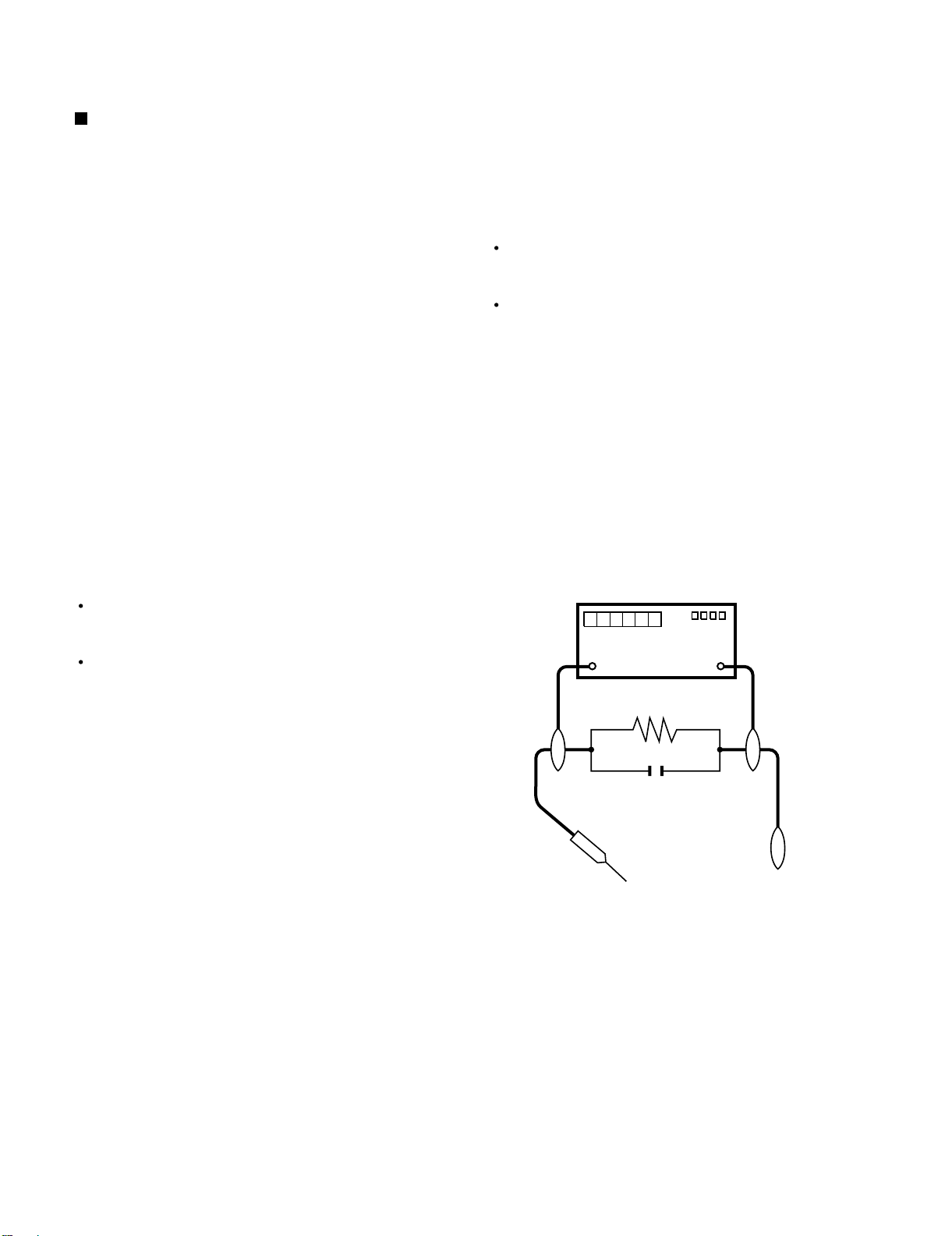
3. To be sure that no shock hazard exists, check for
current leakage in the following manner:
Plug the AC cord directly into a 120-volt AC outlet, (Do
not use an isolation transformer for this test).
Using two clip leads, connect a 1.5k ohm, 10 watt
resistor paralleled by a 0.15μF capacitor in parallel
between all exposed metal cabinet parts and earth
ground.
Service Manual
Use an AC voltmeter with sensitivity of 5000 ohm per
volt., or higher, sensitivity to measure the AC voltage
drop across the resistor.
All checks must be repeated with the AC plug
connection reversed. (If necessary, a non-polarized
adapter plug must be used only for the purpose of
completing these checks.)
Any reading of 0.3 volts RMS (this corresponds to 0.2
milliamp. AC.) or more is excessive and indicates a
potential shock hazard which must be corrected before
returning the unit to the owner.
DVM
AC SCALE
1.5k ohm
10W
0.15 μF
TEST PROBE
TO EXPOSED
METAL PARTS
CONNECT TO
KNOWN EARTH
GROUND
/////////////////////////////////////////////////////////////////////////////////////////////////////////////////////////////////////////////////
SAFETY NOTICE
Many electrical and mechanical parts in DMD™
Projector have special safety-related characteristics.
These characteristics are often not evident from visual
inspection, nor can protection afforded by them be
necessarily increased by using replacement components
rated for higher voltage, wattage, etc.
Replacement parts which have these special safety
characteristics are identified in this manual; electrical
components having such features are identified by “ ”
and shaded areas in the Replacement Parts Lists and
Schematic Diagrams. For continued protection,
replacement parts must be identical to those used in
the original circuit. The use of a substitute replacement
parts which do not have the same safety characteristics
as the factory recommended replacement parts shown
in this service manual, may create shock, fire or other
hazards.
WARNING: The bimetallic component has the primary
conductive side exposed. Be very careful in
handling this component when the power is on.
AVIS POUR LA SECURITE
De nombreuses pièces, électriques et mécaniques, dans
les projecteur à DMD™ présentent des caractéristiques
spéciales relatives à la sécurité, qui ne sont souvent pas
évidentes à vue.
Le degré de protection ne peut pas être nécessairement
augmentée en utilisant des pièces de remplacement
étalonnées pour haute tension, puissance, etc.
Les pièces de remplacement qui présentent ces
caractéristiques sont identifiées dans ce manuel;
les pièces électriques qui présentent ces particularités
sont identifiées par la marque “ ” et hachurées dans la
liste des pièces de remplacement et les diagrammes
schématiques. Pour assurer la protection, ces pièces
doivent être identiques à celles utilisées dans le circuit
d’origine. L’utilisation de pièces qui n’ont pas les mêmes
caractéristiques que les pièces recommandées par l’usine,
indiquées dans ce manuel, peut provoquer des
électrocutions, incendies ou autres accidents.
AVERTISSEMENT: La composante bimétallique dispose du
conducteur primaire dénudé. Faire attention
lors de la manipulation de cette
composante sous tension.
/////////////////////////////////////////////////////////////////////////////////////////////////////////////////////////////////////////////////
i
Page 3
XG-C330X/C430X
PRECAUTIONS A PRENDRE LORS DE LA REPARATION
Ne peut effectuer la réparation qu' un technicien spécialisé qui s'est parfaitement
accoutumé à toute vérification de sécurité et aux conseils suivants.
AVERTISSEMENT
1. N'entreprendre aucune modification de tout circuit.
C'est dangereux.
2. Débrancher le récepteur avant toute réparation.
VERIFICATIONS CONTRE L'INCEN-DIE ET
LE CHOC ELECTRIQUE
Avant de rendre le récepteur à l'utilisateur, effectuer
les vérifications suivantes.
1. Inspecter tous les faisceaux de câbles pour s'assurer
que les fils ne soient pas pincés ou qu'un outil ne soit
pas placé entre le châssis et les autres pièces
métalliques du récepteur.
2. Inspecter tous les dispositifs de protection comme les
boutons de commande non-métalliques, les isolants, le
dos du coffret, les couvercles ou blindages de réglage
et de compartiment, les réseaux de résistance-capacité,
les isolateurs mécaniques, etc.
3. S'assurer qu'il n'y ait pas de danger d'électrocution en
vérifiant la fuite de courant, de la facon suivante:
Brancher le cordon d'alimentation directem-ent à une
prise de courant de 120 V. (Ne pas utiliser de transformateur d'isolation pour cet essai).
A l'aide de deux fils à pinces, brancher une résistance
de 1.5 kΩ 10 watts en parallèle avec un condensateur
de 0.15μF en série avec toutes les pièces métalliques
exposées du cof fret et une terre connue comme une
conduite électrique ou une prise de terre branchée à la
terre.
Utiliser un voltmètre CA d'une sensibilité d'au moins
5000Ω/V pour mesurer la chute de tension en travers
de la résistance.
Toucher avec la sonde d'essai les pièces métalliques
exposées qui présentent une voie de retour au châssis
(antenne, coffret métallique, tête des vis, arbres de
commande et des boutons, écusson, etc.) et mesurer la
chute de tension CA en-travers de la résistance. Toutes
les vérifications doivent être refaites après avoir inversé
la fiche du cordon d'alimentation. (Si nécessaire, une
prise d'adpatation non polarisée peut être utilisée dans
le but de terminer ces vérifications.)
Tous les courants mesurés ne doivent pas dépasser 0.2
mA.
Dans le cas contraire, ilyaunepossibilité de choc
électrique qui doit être supprimée avant de rendre le
récepteur au client.
DVM
ECHELLE CA
1.5k ohm
10W
AUX PIECES
METALLIQUES
EXPOSEES
ii
0.15 μF
SONDE D'ESSAI
BRANCHER A UNE
TERRE CONNUE
Page 4
XG-C330X/C430X
NOTE POUR LE PERSONNEL
D’ENTRETIEN
PRECAUTION POUR LES RADIATIONS UV
La source de lumière, la lampe UHP, dans le projecteur
LCD émet de petites quantités de radiation UV.
EVITEZ TOUTE EXPOSITION DIRECTE DES
YEUX ET DE LA PEAU.
Pour votre sécurité, nous vous prions de respecter
les points suivants:
Précautions pour les radiations UV
et la lampe moyenne pression
NOTE TO SERVICE
PERSONNEL
UV-RADIATION PRECAUTION
The light so urce, UHP lamp, in the LCD projector
emits small amounts of UV-Radiation.
AVOID DIRECT EYE AND SKIN EXPOSURE.
To ensure safety please adhere to the following:
UV-Radiation and Medium Pressure
Lamp Precautions
//////////////////////////////////////////////////////////////
//////////////////////////////////////////////////////////////
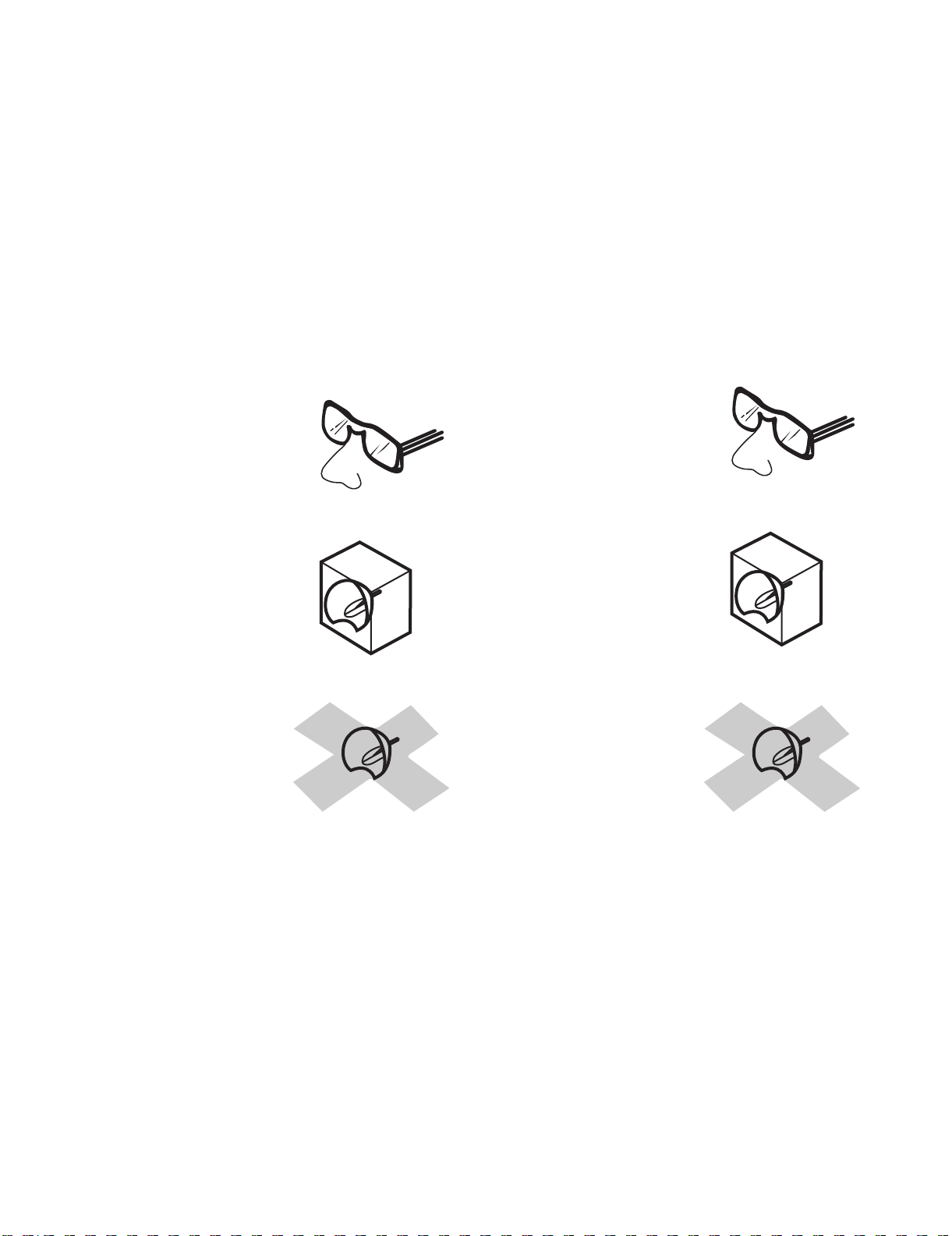
1. Be sure to wear sun-glasses when servicing the
projector with the lamp
turned “on” and the top
enclosure removed.
2. Do not operate the lamp outside of the lamp housing.
//////////////////////////////////////////////////////////////
//////////////////////////////////////////////////////////////
1. Toujours porter des lunettes de soleil lors d’un entretien
du projecteur
avec la lampe allumée
et le haut du coffret retiré.
2. Ne pas faire fonctionner la lampe à l’extérieur du boîtier
de lampe.
3. Do not operate for more than 2 hours with the enclosure
removed.
1. Be sure to disconnect the AC plug when replacing the
lamp.
2. Allow one hour for the unit to cool down before
servicing.
3. Replace only with same type lamp. Type AN-C430LP
rated 275 W AC.
4. The lamp emits small amounts of UV-Radiation, avoid
direct-eye contact.
5. The medium pressure lamp involves a risk of explosion.
Be sure to follow installation instructions described
below and handle the lamp with care.
3. Ne pas faire fonctionner plus de 2 heures avec le coffret
retiré.
1. Toujours débrancher la fiche AC lors du remplacement
de la lampe.
2. Laisser l’unité refroidir pendant une heure avant de
procéder à l’entretien.
3. Ne remplacer qu’avec une lampe du même type. Type
AN-C430LP, caractéristique 275 W-AC.
4. La lampe émet de petites quantités de radiation UVéviter tout contact direct avec les yeux.
5. La lampe moyenne pression implique un risque
d’explosion. Toujours suivre les instructions
d’installation décrites ci-dessous et manipuler la lampe
avec soin.
iii
Page 5
XG-C330X/C430X
Remplacement de la lampe
Remarque:
DANGER !
UV-RADIATION PRECAUTION (Continued)
Lamp Replacement
Note:
DANGER !
PRECAUTION POUR LES RADIA
////////////////////////////////////////////////////////////////
////////////////////////////////////////////////////////////////
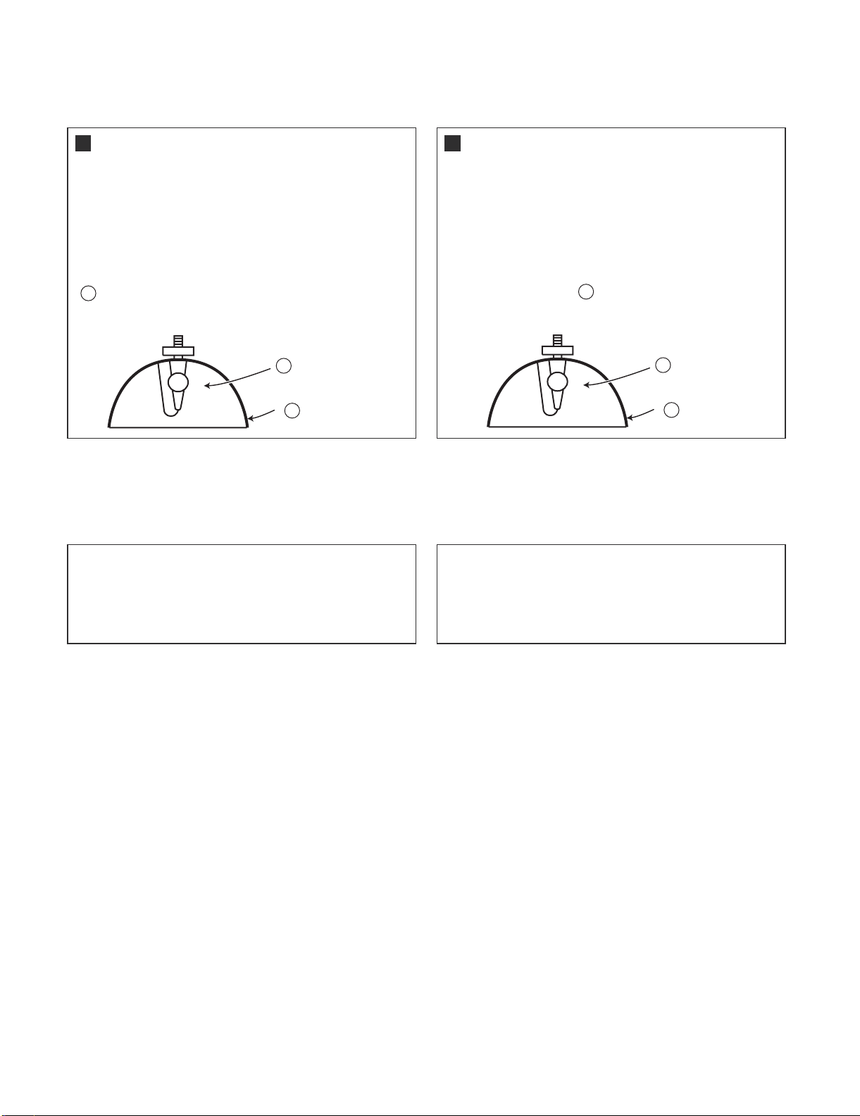
Since the lamp reaches a very high temperature during
units operation replacement of the lamp should be
done at least one hour after the power has been turned
off. (to allow the lamp to cool off.)
Installing the new lamp, make sure not to touch the
lamp (bulb) replace the lamp by holding its reflector
2
.
[Use original replacement only.]
Lamp
1
Reflector
2
–– Never turn the power on without the
lamp to avoid electric-shock or damage of the devices
since the stabilizer generates high voltages at its start.
////////////////////////////////////////////////////////////////
////////////////////////////////////////////////////////////////
Comme la lampe devient très chaude pendant le
fonctionnement de l’unité, son remplacement ne doit
être effectué au moins une heure après avoir coupé
l’alimentation (pour permettre à la lampe de refroidir).
En installant la nouvelle lampe, s’assurer de ne pas
toucher la lampe (ampoule). Remplacer la lampe en
tenant son réflecteur .
[N’utiliser qu’un remplacement d’origine.]
–– Ne jamais mettre sous tension sans la
lampe pour éviter un choc électrique ou des
dommages des appareils car le stabilisateur génère
de hautes tensions à sa mise en route.
2
TIONS UV (Suite)
1
Lampe
2
Reflecteur
Since small amounts of UV-radiation are emitted
from an opening between the exhaust fans, it is recommended to place the cap of the optional lens on
the opening during servicing to avoid eye and skin
exposure.
Comme de petites quantités de radiation UV sont
émises par une ouverture entre les ventilateurs aspirants, il est recommandé de placer le capuchon de
l’optique optionnelle sur l’ouverture pendant l’entretien
pour éviter une exposition des yeux et la peau.
iv
Page 6
XG-C330X/C430X
WARNING: High brightness light source, do not stare into the beam of light, or view directly. Be especially
careful that
children do not stare directly in to the beam of light.
WARNING: TO REDUCE THE RISK OF FIRE OR ELECT RIC SHOCK, DO NOT EXPOSE
THIS UNIT TO
MOISTURE OR WET LOCATIONS.
CAUTION
AVERTISSEMENT: Source lumineuse de grande intensité. Ne pas fixer le faisceau lumineux ou le regarder
directement. Ve
iller particulièrement à éviter que les enfants ne fixent directement le
faisceau lumineux.
AVERTISSEMENT: AFIN D’EV
ITER TOUT RISQUE D’INCENDIE OU D’ELECTROCUTION, NE PAS PLACER
CET APPAREIL DANS UN ENDROIT HUMIDE OU MOUILLE.
ATTENTION
CAUTION
(INLET Unit)
PRECAUTION
(Unité d'admission)
CAUTION: TO REDUCE THE RISK OF ELECTRIC SHOCK,
6.3A 250V
NO USER-SERVICEABLE PARTS EXCEPT LAMP UNIT.
REFER SERVICING TO QUALIFIED SERVICE
RISK OF ELECTRIC SHOCK.
DO NOT REMOVE SCREWS
EXCEPT SPECIFIED USER
SERVICE SCREW.
DO NOT REMOVE CABINET.
PERSONNEL.
For continued
protection against a
risk of fire, replace
only with same type
fuse. 6.3A, AC250V (F801)
The lighting flash with arrowhead within a
triangle is intended to tell the user that
parts inside the product are risk of electric
shock to persons.
The exclamation point within a triangle is
intended to tell the user that important
operating and servicing instructions are in
the manual with the projector.
//////////////////////////////////////////////////////////////////////////////////////////////////////////////////////////////////
L’EXCEPTION DE LA VIS DE
REPARATION UTILISATEUR
RISQUE
D’ÉLECTROCUTION. NE
PASR ETIRER LES VIS Á
L’éclair terminé d’une flèche à l’intérieur
d’un triangle indique à l’utilisateur que les
pi‘eces se trouvant dans l’appareil sont
susceptibles de provoquer une décharge
électrique.
SPECIFIEES
Le point d’exclamation à l’intérieur d’un
D’ELECTROCUTION, NE PAS RETIRER LE CAPOT.
AUCUNE DES PIECES INTERIEURES N’EST REPARABLE
PAR L’UTILISATEUR, A L’EXCEPTION DE L’UNITE DE
LAMPE. POUR TOUTE REPARATION, S’ADRESSER A UN
6.3A 250V
ATTENTION: POUR EVITER TOUT RISQUE
TECHNICIEN D’ENTRETIEN QUALIFIE.
Pour une protection
continue contre un
risques d’incendie, ne
remplacer qu’avec un
fusible du même type fuse.
6.3A, AC250V (F801)
triangle indique à l’utilisateur que les
instructions de fonctionnement et
d’entretien sont détaillées dans les
documents fournis avec le projecteur.
v
Page 7
XG-C330X/C430X
Precautions for using lead-free solder
Employing lead-free solder
• "PWBs" of this model employs lead-free solder. The LF symbol indicates lead-free solder, and is attached on the PWBs and service manuals. The
alphabetical character following LF shows the type of lead-free solder.
Example:
L Fa
Indicates lead-free solder of tin, silver and copper.
Using lead-free wire solder
• When fixing the PWB soldered with the lead-free solder, apply lead-free wire solder. Repairing with conventional lead wire solder may cause damage or accident due to cracks.
As the melting point of lead-free solder (Sn-Ag-Cu) is higher than the lead wire solder by 40 °C, we recommend you to use a dedicated soldering
bit, if you are not familiar with how to obtain lead-free wire solder or soldering bit, contact our service station or service branch in your area.
Soldering
• As the melting point of lead-free solder (Sn-Ag-Cu) is about 220 °C which is higher than the conventional lead solder by 40 °C, and as it has poor
solder wettability, you may be apt to keep the soldering bit in contact with the PWB for extended period of time. However, Since the land may be
peeled off or the maximum heat-resistance temperature of parts may be exceeded, remove the bit from the PWB as soon as you confirm the
steady soldering condition.
Lead-free solder contains more tin, and the end of the soldering bit may be easily corroded. Make sure to turn on and off the power of the bit as
required.
If a different type of solder stays on the tip of the soldering bit, it is alloyed with lead-free solder. Clean the bit after every use of it.
When the tip of the soldering bit is blackened during use, file it with steel wool or fine sandpaper.
• Be careful when replacing parts with polarity indication on the PWB silk.
Lead-free wire solder for servicing
Part No. Description Code
ZHNDAi123250E J φ0.3mm 250g(1roll) BL
ZHNDAi126500E J φ0.6mm 500g(1roll) BK
ZHNDAi12801KE J φ1.0mm 1kg(1roll) BM
vi
Page 8
XG-C330X/C430X
XG-C330X
CHAPTER 1. OPERATION MANUAL
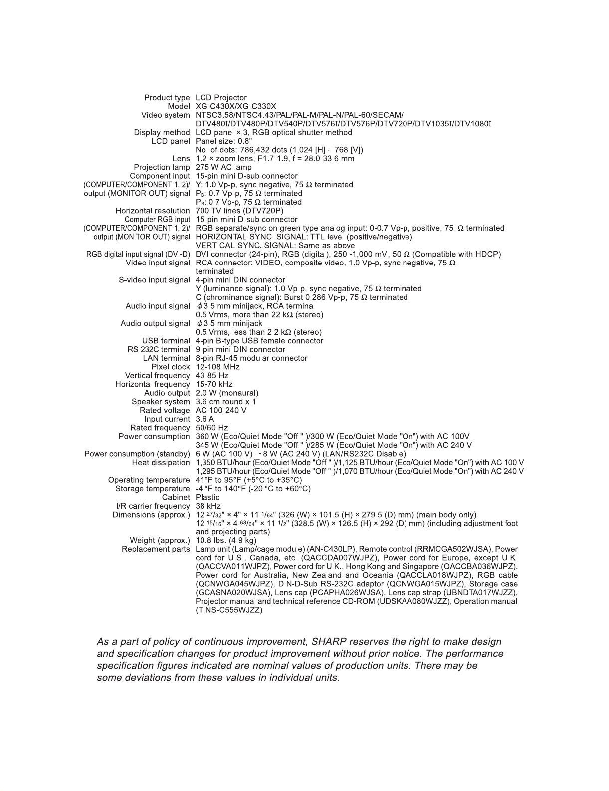
[1] Specifications
Service Manual
1 – 1
Page 9
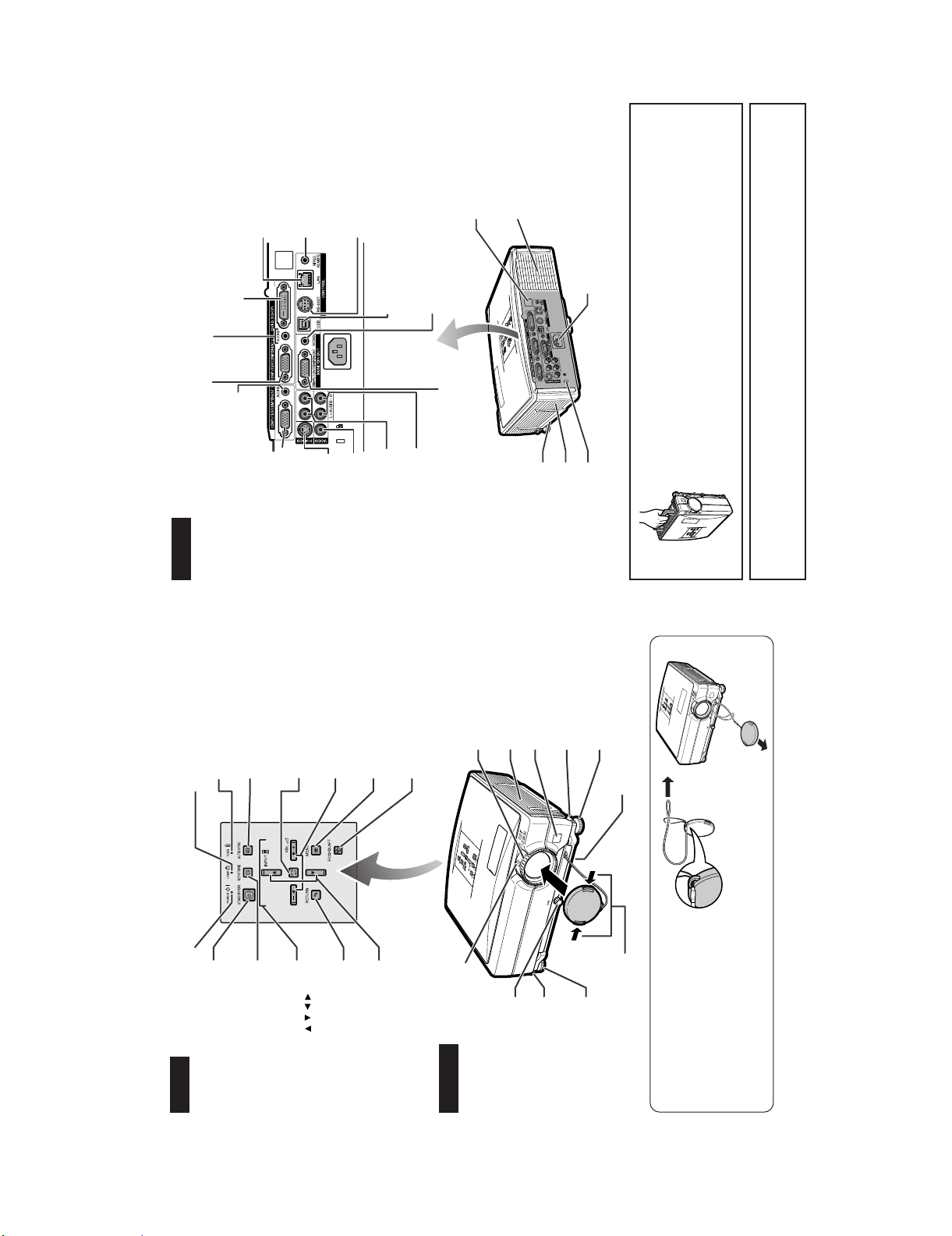
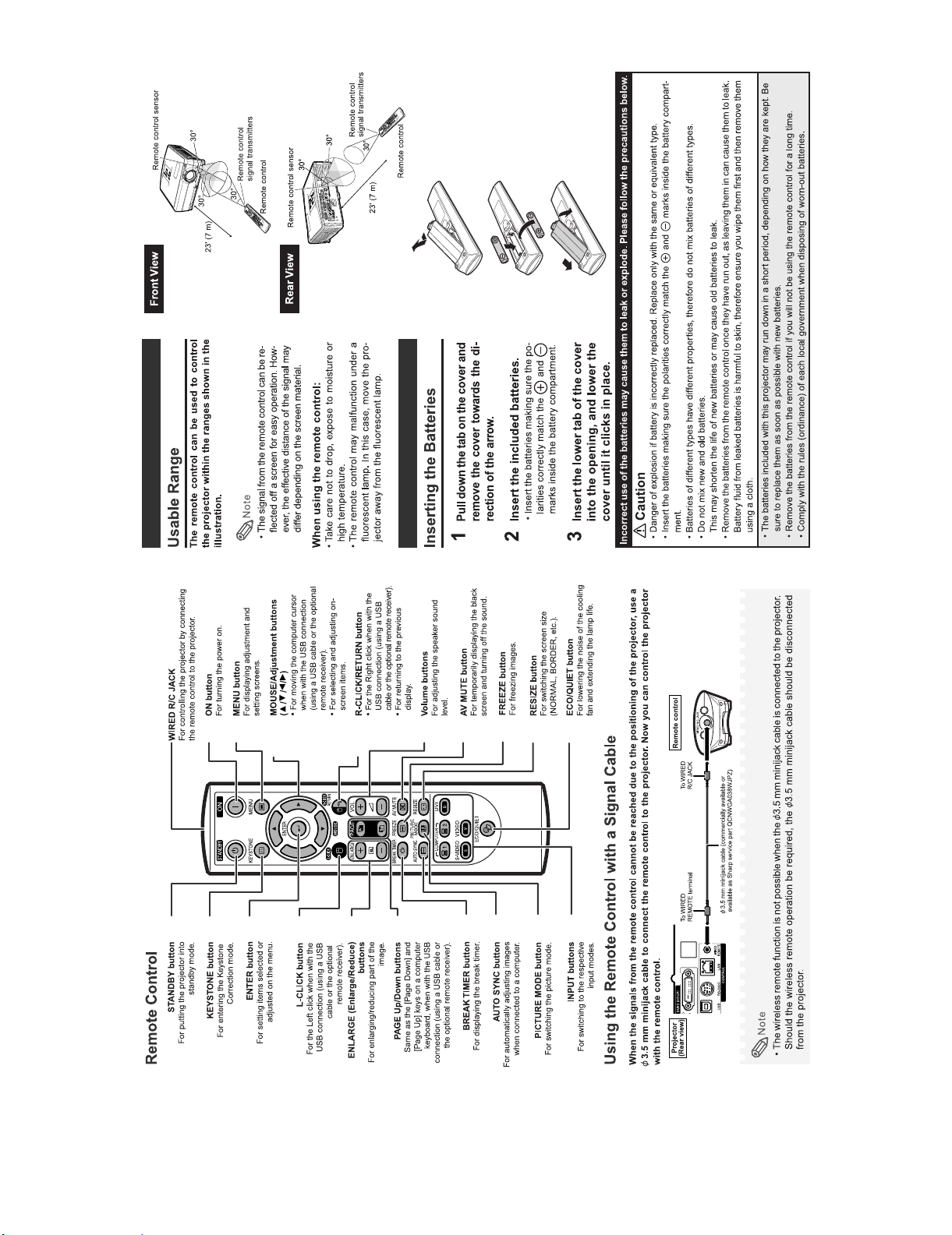
[2] Parts Name and Basic Operation
WIRED REMOTE terminal
For connecting the remote control
to the projector when the signals
from the remote control cannot
reach the remote control sensor.
RS-232C terminal
Terminal for controlling the
AUDIO input terminal
Shared audio input terminal for COMPUTER/COMPONENT 2 and
DVI-D.
á
DVI-D input terminal
Terminal for DVI Digital RGB and Digital Component
signals.
25
á
á
23
LAN terminal
Terminal for controlling the
projector using a computer
via network.
projector using a computer.
USB terminal
XG-C330X/C430X
Exhaust vent
Remote control
sensor
Connect the supplied power cord.
AC socket
AUDIO output terminal
Terminal connecting with the USB terminal on the
computer for using the supplied remote control as the
computer mouse.
projector.
Using the Carrying Handle
Component signals.
the lens.
When transpor ting the projector, carry it by the carrying handle on the side.
• Always put on the lens cap to prevent damage to the lens when transporting the
• Do not lift or carry the projector by the lens or the lens cap as this may damage
Terminals
Projector (Rear View)
Terminal for Computer RGB and Component signals.
COMPUTER/COMPONENT 2 input terminal
Temperature warning
Lamp indicator
Audio input terminal for
AUDIO input terminal
AUTO SYNC button
indicator
COMPUTER/COMPONENT 1.
For automatically adjusting
images when connected to
input terminal
COMPUTER/COMPONENT 1
Terminal for Computer RGB
ENTER button
a computer.
and Component signals.
For setting items selected
or adjusted on the menu.
S-VIDEO input terminal
Volume buttons
For adjusting the speaker
VIDEO input terminal
sound level.
AUDIO input terminal
MENU button
For displaying adjustment
for S-video
and setting screens.
for Video
AUDIO input terminal
For lowering the noise of the
ECO/QUIET button
cooling fan and extending the
MONITOR output terminal
Output terminal for Computer RGB and
lamp life.
Carrying handle
Intake vent
Standard connector
sensor
* Kensington Security
Height Adjustment
button
Adjustment foot
Air filter/Intake vent
(on the bottom of the projector)
* Using the Kensington Lock
System. Refer to the information that came with the system for instructions on how to use it to secure the
• This projector has a Kensington Security Standard connector for use with a Kensington MicroSaver Security
projector.
Shared for COMPUTER/COMPONENT 1 and 2.
For adjusting the focus.
Focus ring
Speaker
Remote control
Power indicator
Top View
Projector
STANDBY/ON button
For turning the power on and
putting the projector into
standby mode.
KEYSTONE button
For entering the Keystone
Correction mode.
(///)
Adjustment buttons
on-screen items.
For selecting and adjusting
RETURN button
For returning to the previous
display.
INPUT buttons
For switching input mode.
Zoom knob
Front View
1 – 2
For enlarging/
reducing the picture.
Tilt dial
button
Height Adjustment
Adjustment foot
attach or remove.
Push both sides of the lens cap to
Attaching the lens cap
After putting the lens cap strap on the lens
cap, pass the other end of the strap
through the hole on the front side of the
projector, next to the lens, as shown in
the illustration.
Page 10
XG-C330X/C430X
1 – 3
Page 11
XG-C330X/C430X
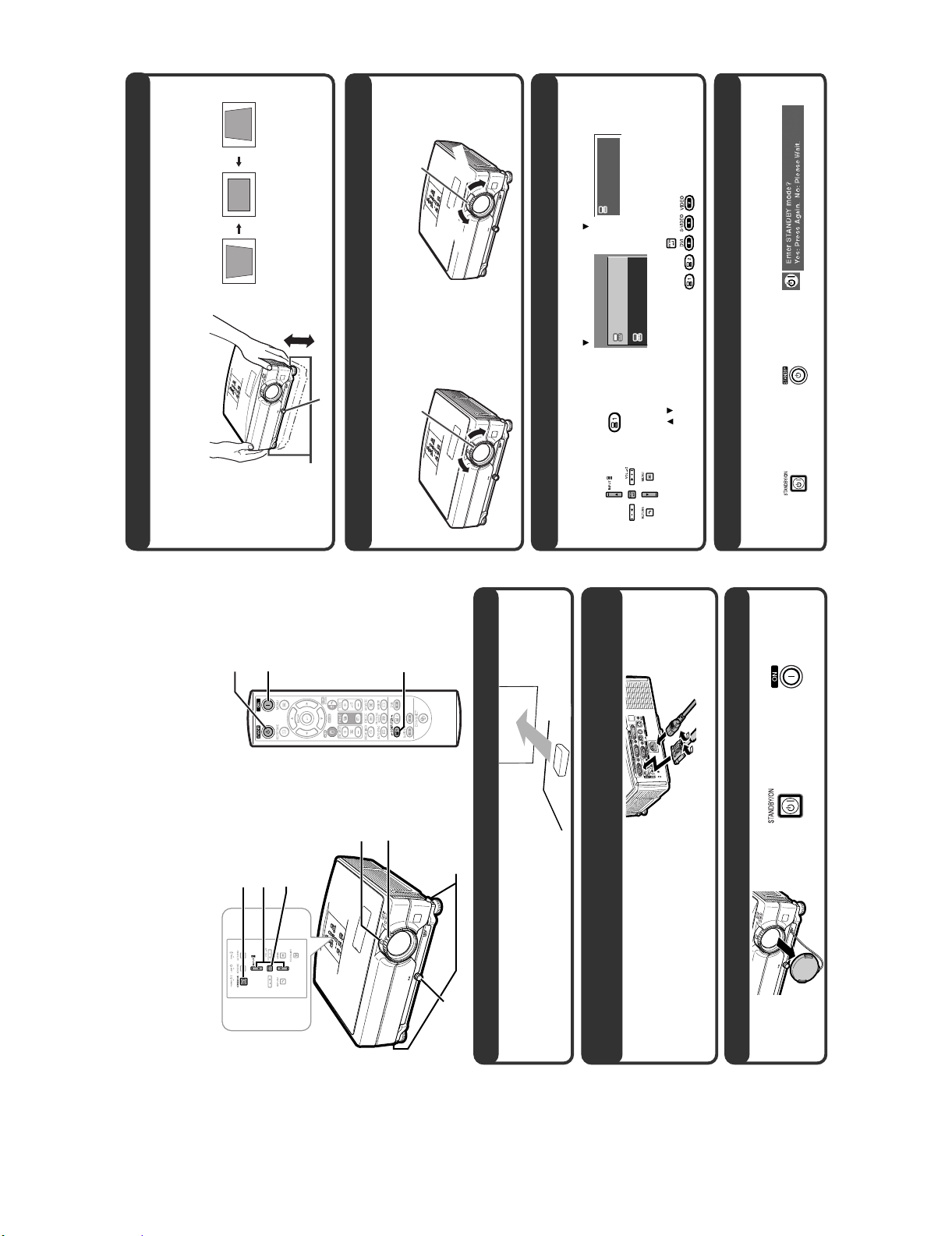
This projector is equipped with an "Auto Keystone
••
••
•
Adjust the projector angle
4. Adjust the angle
Correction" function that automatically corrects
any trapezoidal distortion within the projected
image.
Adjust the projector angle using the Height
Adjustment buttons.
••
••
•
n
i
Tilt dial
Zoom knob
zoom knob.
••
••
• Adjust the projected image size by moving the
Adjust the projected image size
Focus ring
Zoom
om out
Zo
Select the INPUT mode
Rotate the Tilt dial to adjust the horizontal tilt of
the projector.
••
••
•
Height Adjustment
buttons
Bring the projected image into focus
5. Adjust the focus and the zoom
rotating the focus ring.
••
••
• Bring the projected image into focus by
6.
On-screen Display (RGB)
INPUT list
On the remote
On the
Select the "COMPUTER 1" using the INPUT buttons on the projector or the COMPUTER 1 button on the remote
control.
RGB
1024 × 768
COMPUTER 1
1
INPUT
control
projector
/ / to switch the INPUT mode.
/ /
COMPUTER 1
COMPUTER 2
1
2
Press / to select an item on the list, and press to switch to the selected INPUT mode.
••
••
••
••
• When you press the INPUT buttons on the projector, the INPUT list appears.
• When using the remote control,press
Tu rn the Power off
7.
On-screen Display
On the remote controlOn the projector
ANDBY button, then press that button again while the confirmation message is displayed, to put
ojector into standby mode.
Press the ST
the pr
ou unplug the power cord from the AC outlet, the cooling fan continues to run for a while.
••
••
• Even if y
This section shows the basic operation (projector connecting with the computer). For details, see the page
described below for each step.
button
STANDBY
STANDBY/ON button
Setup and Projection
In this section, connection of the projector and the computer is explained using one example.
ON button
INPUT buttons
ENTER button
Zoom knob
COMPUTER 1
button
On the remote controlOn the projector
Focus ring
Height Adjustment buttons
Tilt dial
1. Place the projector facing a screen
cor d into the AC socket of the projector
2. Connect the projector to the computer and plug the power
When connecting equipment other than the computer, see OPERATION MANUAL.
3. Remove the lens cap and turn the projector on
1 – 4
Page 12
XG-C330X/C430X
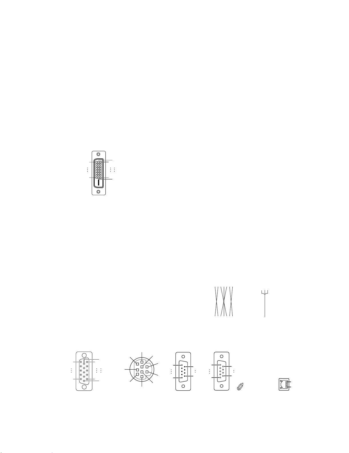
13 Not connected
14 +5 V Power
Pin No. Signal
1 T.M.D.S. Data 2-
2 T.M.D.S. Data 2+
Pin No. Signal
1724
15 Ground
16 Hot Plug Detect
3 T.M.D.S. Data 2 Shield
4 Not connected
17 T.M.D.S.Data 0-
18 T.M.D.S.Data 0+
19 T.M.D.S.Data 0 Shield
20 Not connected
5 Not connected
6 DDC Clock
7 DDC Data
8 Not connected
21 Not connected
22 T.M.D.S.Clock Shield
23 T.M.D.S.Clock+
9 T.M.D.S. Data 1-
10 T.M.D.S.Data 1+
11 T.M.D.S.Data1Shield
9
1
8
16
24 T.M.D.S.Clock-
12 Not connected
Connecting Pin Assignments
DVI-D Input Terminal
:
)
)
R
B
(C
(C
R
B
1. P
4. Not connected
5. Not connected
2. Y
3. P
Component Input/Output
2 and COMPUTER-RGB/COMPONENT OUTPUT Terminals
1. Video input (red)
2. Video input (green/sync on green)
3. Video input (blue)
4. Not connected
5. Not connected
COMPUTER-RGB Input/Output
15
11
COMPUTER-RGB/COMPONENT INPUT 1,
15-pin mini D-sub female connector
)
R
6. Earth (P
6. Earth (red)
7. Earth (Y)
7. Earth (green/sync on green)
)
B
9. Not connected
8. Earth (P
8. Earth (blue)
9. Not connected
10. Not connected
11. Not connected
12. Not connected
10. GND
11. Not connected
12. Bi-directional data
10
5
1
6
13. Not connected
14. Not connected
15. Not connected
13. Horizontal sync signal:TTL level
14. Vertical sync signal: TTL level
15. Data clock
1 Not connected
2 RD Receive Data Input Connected to internal circuit
Pin No. Signal Name I/O Reference
7
8
9
RS-232C Terminal: 9-pin mini DIN female connector
3 SD Send Data Output Connected to internal circuit
4 Not connected
5 SG Signal Ground Connected to internal circuit
6 Not connected
7 RS Request to Send Connected to CS in inter nal circuit
8 CS Clear to Send Connected to RS in inter nal circuit
9 Not connected
3
6
4
5
12
RS-232C Terminal: 9-pin D-sub male connector of the DIN-D-sub RS-232C adaptor
1 Not connected
2 RD Receive Data Input Connected to internal circuit
3 SD Send Data Output Connected to internal circuit
4 Not connected
5 SG Signal Ground Connected to internal circuit
Pin No. Signal Name I/O Reference
6 Not connected
15
7 RS Request to Send Connected to CS in inter nal circuit
8 CS Clear to Send Connected to RS in inter nal circuit
9 Not connected
69
1CD 1 CD
2RD 2 RD
Pin No. Signal Pin No. Signal
51
RS-232C Cable recommended connection: 9-pin D-sub female connector
3SD 3 SD
4ER 4 ER
5SG 5 SG
6DR 6 DR
7RS 7 RS
8CS 8 CS
9CI 9 CI
96
Note
Pin No.
Computer
Pin No.
Projector
device (e.g. computer).
• Depending on the controlling device used, it may be necessary to connect Pin 4 and Pin 6 on the controlling
456
456
1TX+ 5
2TX- 6 RX-
3RX+ 7
48
Pin No. Signal Pin No. Signal
LAN Terminal : 8-pin RJ-45 modular connector
8... 1
1 – 5
Page 13
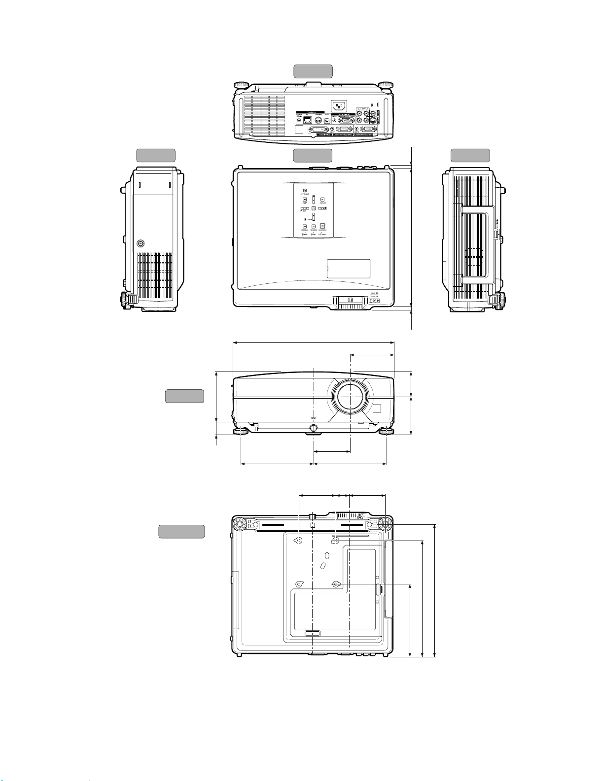
[3] Dimensions
XG-C330X/C430X
Units: inches (mm)
Side View Side View
Rear View
Top View
1227/32 (326)
31
3
/64 (88.5)
17
(6)
4
/
1
(279.5)
64
/
1
11
64
/
(6.5)
Front View
Bottom View
32
/
31
(50)
1
4 (101.5)
64
/
63
(25)
15
/16
2
(76.5)
64
/
1
3
(74.5)
53
/64 (148) 553/64 (148)
5
29
/32
15/64
(27.25)
2
(73.5)
(146.5)
32
/
25
5
(235.5)
32
/
9
9
(268.5)
64
/
37
10
261/64
(75)
1 – 6
Page 14
XG-C330X/C430X
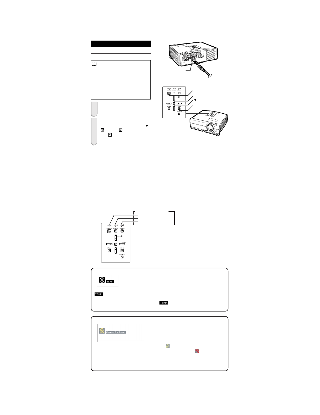
[4] Resetting the total lamp timer
When replacing the lamp, reset the total lamp timer in the procedure
below.
Resetting the Lamp Timer
Reset the lamp timer after replacing the lamp.
Info
Make sure to reset the lamp timer only
when replacing the lamp. If you reset the
lamp timer and continue to use the same
lamp, this may cause the lamp to become
damaged or explode.
You can also reset the lamp timer via the
LAN.
(Refer to the SETUP MANUAL on the supplied CD-ROM for details.)
1 Connect the power cord.
Plug the power cord into the AC socket
of the projector.
2 Reset the lamp timer.
While simultaneously holding down ,
ENTER and MENU on the projector,
STANDBY/ON on the projector.
press
"LAMP 0000H" is displayed, indicating
that the lamp timer is reset.
AC socket
STANDBY/ON button
ENTER button
button
MENU button
Lamp
• It is recommended that the lamp unit (optional: AN-C430LP) be
replaced when the remaining lamp life becomes 5% or less, or
when you notice a significant deterioration in the picture and color
quality. The lamp life (percentage) can be checked with the onscreen display.
• Purchase a replacement lamp unit of type AN-C430LP from your
place of purchase, nearest Sharp Authorized Projector Dealer or
Service Center.
Maintenance Indicators
Power indicator
Lamp indicator
Temperature warning indicator
About the temperature warning indicator
If the temperature inside the projector increases, due to blockage of the air vents, or the setting location,
" " will illuminate in the lower left corner of the picture. If the temperature keeps on rising, the lamp will
turn off and the temperature war ning indicator will blink, the cooling fan will run for a further 90 seconds, and
then the projector will enter the standby mode. After "
• The warning lights on the projector indicate problems inside the
projector.
• If a problem occurs, either the temperature indicator or the lamp
indicator will illuminate red, and the projector will enter the standby
mode. After the projector has entered the standby mode, follow the
procedures given below.
" appears, ensure you perform the measures.
About the lamp indicator
When the remaining lamp life becomes 5% or less, " " (yellow) and "Change The Lamp." will be
displayed on the screen. When the percentage becomes 0%, it will change to "
automatically turn off and then the projector will automatically enter the standby mode. At this time,
the lamp indicator will illuminate in red.
If you try to turn on the projector a fourth time without replacing the lamp, the projector will not turn on.
" (red), the lamp will
1 – 7
Page 15
XG-C330X/C430X
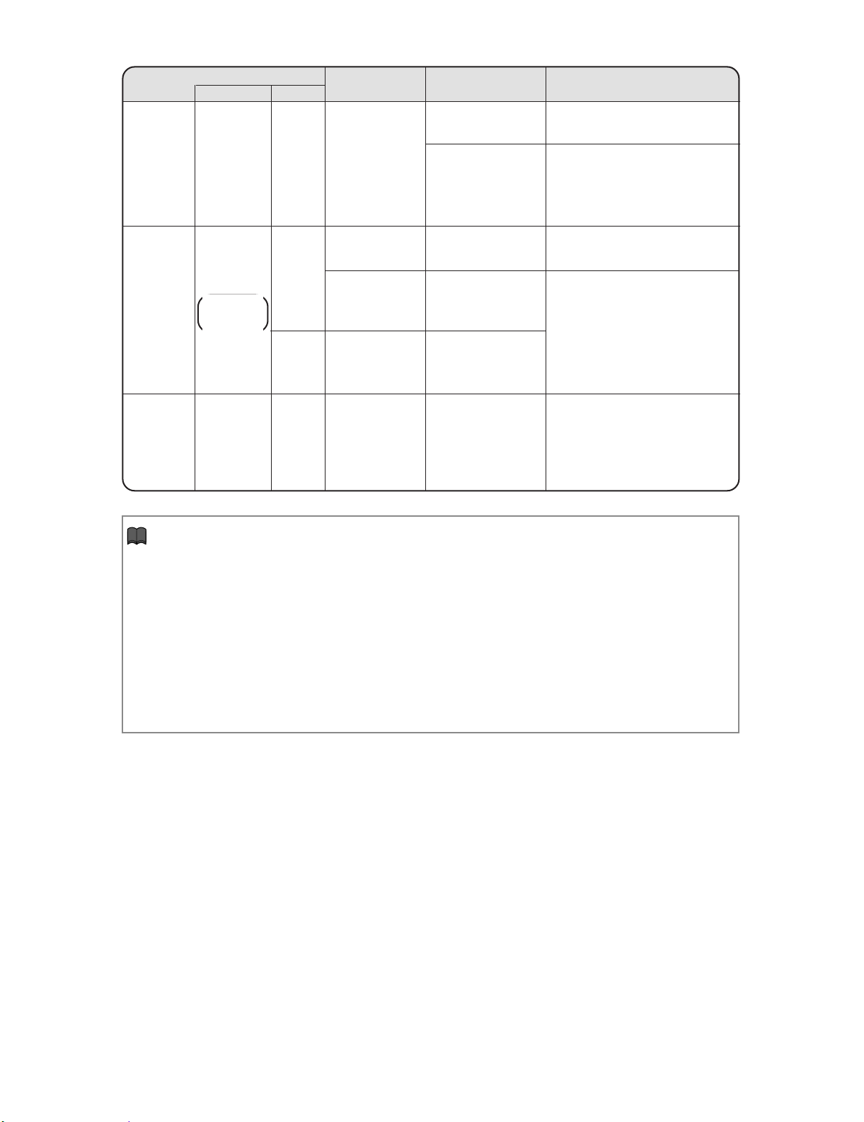
Maintenance indicator
Temperature
warning
indicator
Lamp
indicator
Power
indicator
Normal
Off
Green on
Green blinks
when the lamp
is warming up
Green on/
Red on
Green blinks
(Cooling)
Abnormal
Abnormal
Red on
(Standby)
Red on
Red on
(Standby)
Red blinks
Problem
The internal
temperature is
abnormally high.
The lamp does
not illuminate.
Time to change
the lamp.
The lamp does
not illuminate.
The power
indicator blinks
in red when the
projector is on.
Cause Possible solution
• Relocate the projector to an area
• Blocked air intake
• Cooling fan breakdown
• Internal circuit failure
• Clogged air intake
• The lamp is shut
down abnormally.
• Remaining lamp life
becomes 5% or less.
• Burnt-out lamp
• Lamp circuit failure
• The filter cover, lamp
unit cover or lens
housing cover is
open.
• Cooling fan breakdown
with proper ventilation
• Take the projector to your nearest
Sharp Authorized Projector Dealer
or Service Center
for repair.
• Clean the exhaust and intake
vents.
• Disconnect the power cord from
the AC outlet, and then connect it
again.
• Carefully replace the lamp.
• Take the projector to your nearest
Sharp Authorized Projector Dealer
or Service Center
for repair.
• Please exercise care when
replacing the lamp.
• Securely install the lamp unit cover.
• If the power indicator blinks even
when the covers are securely
installed, or if the cooling fan does
not run normally, then contact your
nearest Sharp Authorized
Projector Dealer or Service Center
for advice.
Info
• If the temperature warning indicator illuminates and the projector enters the standby mode, check whether
any of the ventilation holes are blocked and then try turning the power back on. Wait until the projector
has cooled down completely before plugging in the power cord and turning the power back on.
(At least 10 minutes.)
• If the power is turned off for a brief moment due to power outage or some other cause while using the
projector, and the power supply recovers immediately after that, the lamp indicator will illuminate in red
and the lamp may not be lit. In this case, unplug the power cord from the AC outlet, replace the power
cord in the AC outlet and then tur n the power on again.
• The cooling fan keeps the internal temperature of the projector constant and this function is controlled
automatically. The sound of the cooling fan may change dur ing operation because the fan speed may
change and this is not a malfunction.
1 – 8
Page 16
XG-C330X/C430X
XG-C330X
CHAPTER 2. REMOVING OF MAJOR PARTS
Service Manual
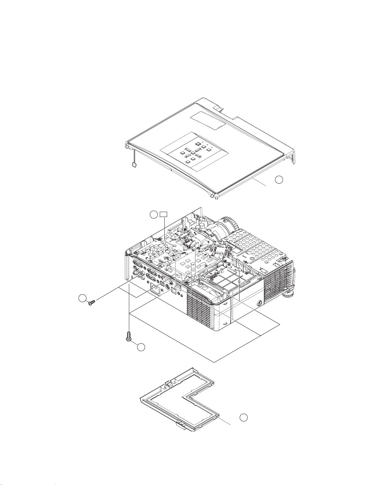
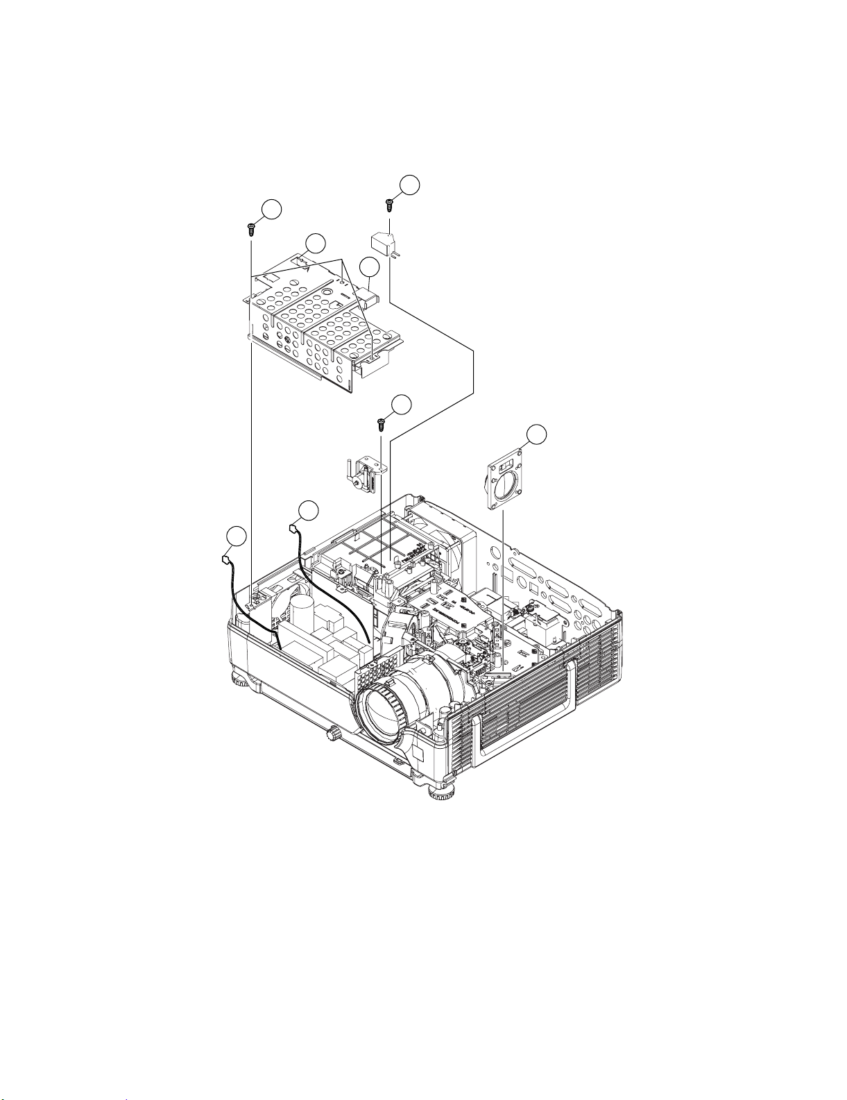
[1] Removing the Top Body and the Intake Cover.
1. Remove the 2 screws from the rear side.
2. Remove the 8 screws from the Top Body.
3. Lift and hold the Top Body . Remove [LF] connector.
4. Detact the Top Body.
5. Detach the Intake Cover.
1-4
Top Body
1-1
1-2
1-3
LF
2 – 1
1-5
Intake Cover
Page 17
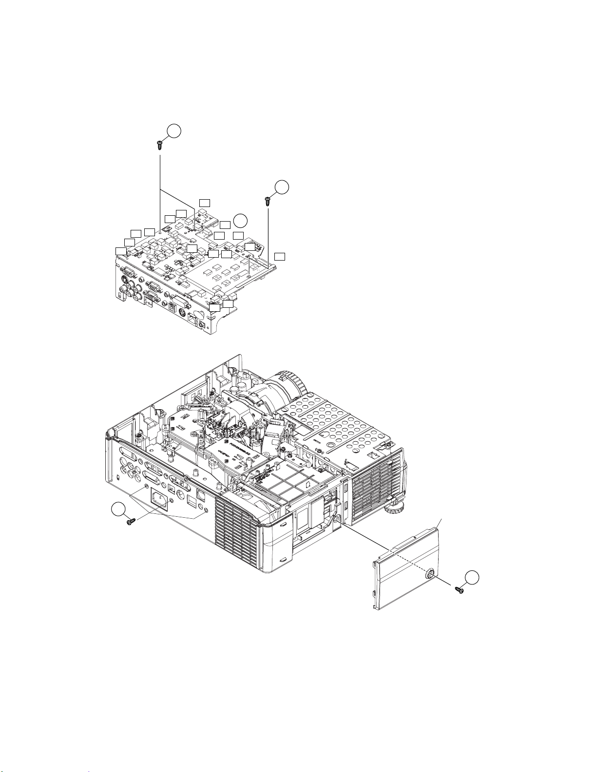
[2] Removing the Connecting Cables and Main PWB.
1. Remove the 3 screws from the rear side.
2. Detach all the Connecting Cables from PWBs.
3. Detach the FFCs (RP, GP, BP) from Main PWB.
4. Remove the 3 screws and detach the Main PWB.
5. Detach the 1 screw and detach the Lamp Door.
2-4
2-4
CP
SO
LL
FE
FD
FC
T0
CP
2-3
RP
BP
GP
T1
FF
FB
EA
XG-C330X/C430X
2-1
T2
FA
Lamp Door
2-5
2 – 2
Page 18
XG-C330X/C430X
[3] Removing the Ballast Ass'y and the Speaker.
1. Remove the 1 screw and detach the Trigger Box.
2. Remove the 3 screws.
3. Remove the 2 cables and detach the Ballast Ass’y.
4. Detach the Speaker.
5. Remove the 1 screw and detach the Bimetal Holder.
3-1
3-2
Trigger
3-3-1
Box
3-2
Ballast Shield
3-5
3-3-2
3-3-2
Bimetal
Holder
3-4
2 – 3
Page 19
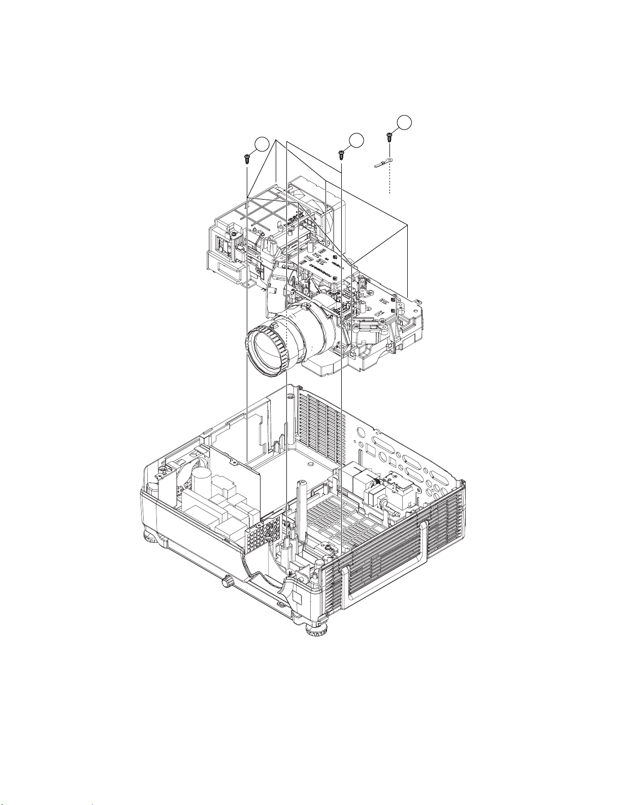
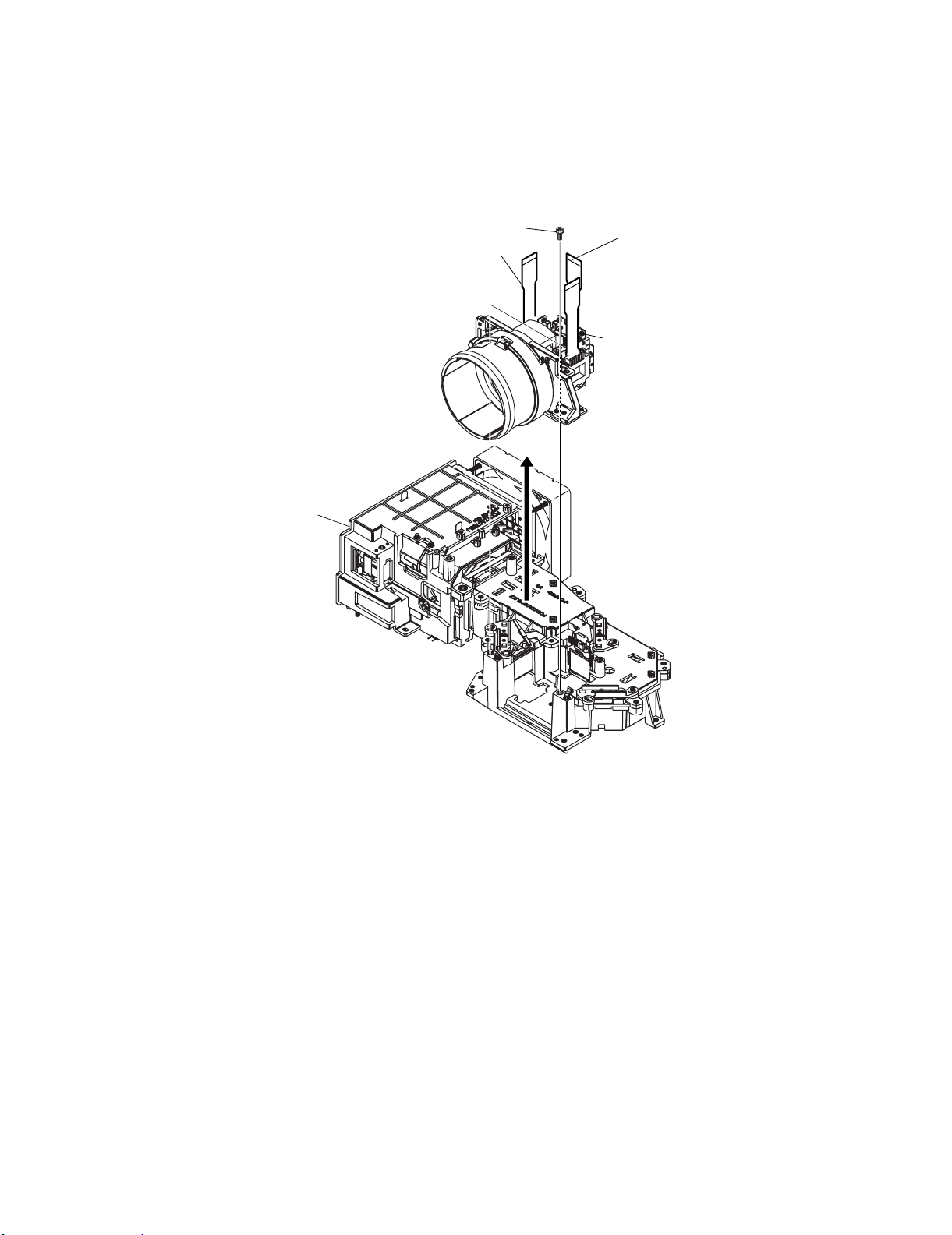
[4] Removing the Optical Mechanism Unit.
1. Remove the 6 screws.
2. Remove the 2 screws.
3. Remove 1 screw and detach the earth lead.
4. Detach the Optical Mechanism Unit.
XG-C330X/C430X
4-3
4-1
4-2
Optical
Mechanism
unit
2 – 4
Page 20
XG-C330X/C430X
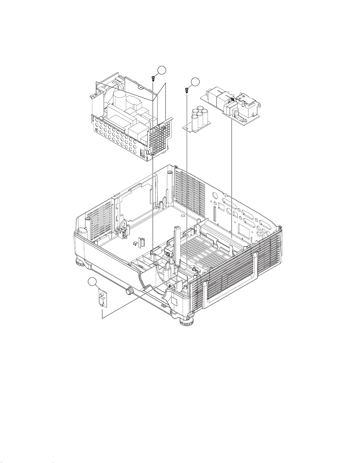
[5] Removing the Power Unit, Inlet Unit, RC Unit and CONDENSER Unit.
1. Remove the 3 screws and Detach the Power Unit.
2. Detach the Inlet Unit.
3. Detach the R/C unit.
4. Remove the 1screw and detach the Condenser Unit.
5-1
5-4
Inlet
Unit
POWER
Unit
Condenser
Unit
5-3
R/C Unit
2 – 5
Page 21
XG-C330X
CHAPTER 3. THE OPTICAL UNIT OUTLINE
Service Manual
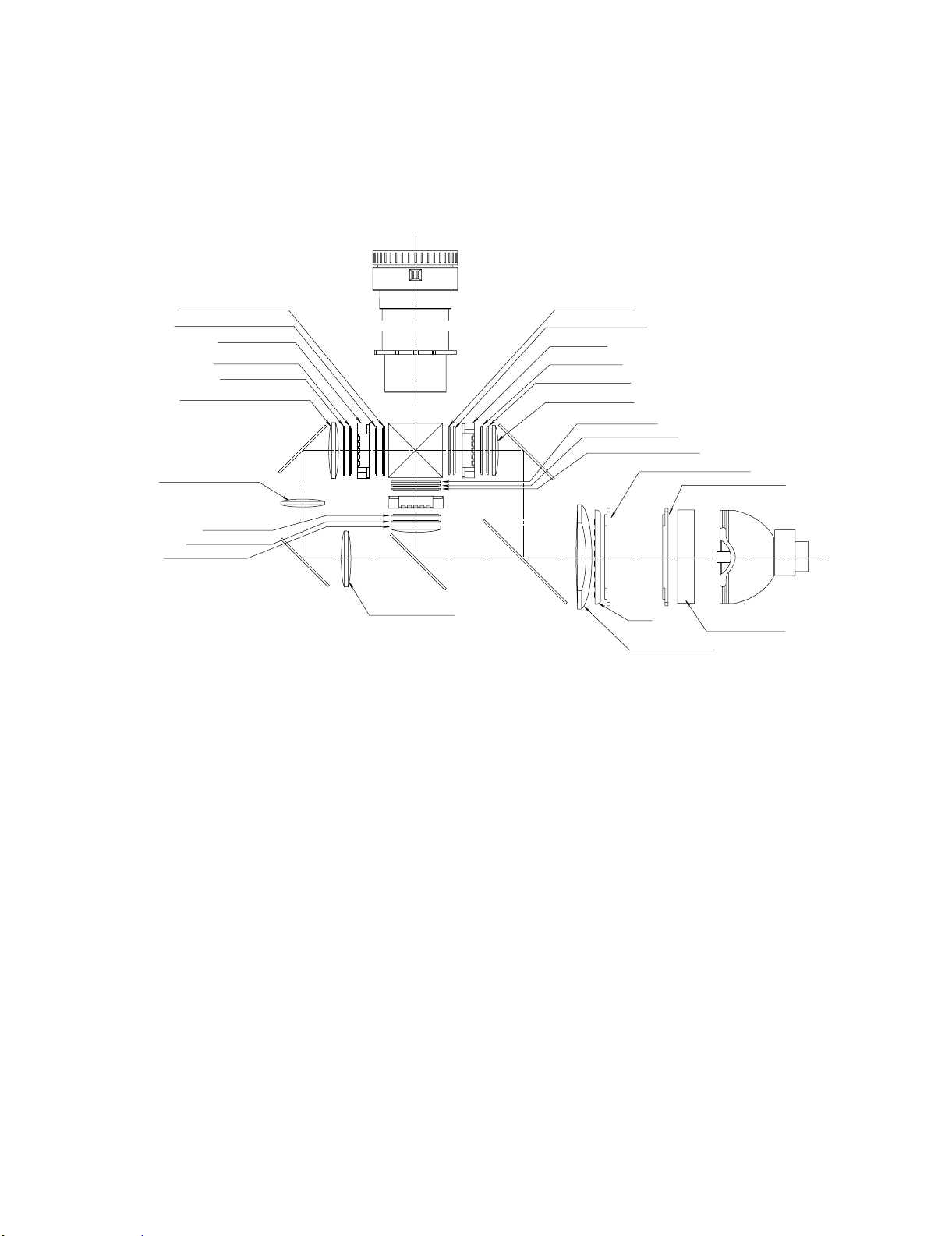
[1] THE OPTICAL UNIT OUTLINE
1. Layout for proper setup of the optical components and parts (top view)
XG-C330X/C430X
Output polarizer R
Output Pre-polarizer R
LCD (R)
Input polarizer R
Dichroic filter R
Condencer lens R
Condencer lens 5
Input polarizer G
Input Pre-polarizer G
Condencer lens G
CL5
M3
M3
Output polarizer B
Input pre-polarizer B
B reflect
M4
o
r
B
r
e
fl
ec
M1
Output pre-polarizer B
LCD (B)
Input polarizer B
Condencer lens B
Output polarizer G
Output pre-polarizer G
Output pre-pre-polarizer G
CL2
tor
PBS
FLYEYE LENS (OUTPUT)
FLYEYE LENS (INPUT)
CL1
Condencer lens 1
Condencer lens 2
Light source
(Lamp)
Projection Lens
Cross dichroic
r
o
t
ec
fl
e
r
R
CL4
R
r
e
f
lect
CL4
o
r
prism
CL3-G
G
ref
M2
Condencer lens 4
LCD (G)
l
e
c
t
o
r
CL3-B
3 – 1
Page 22
XG-C330X/C430X
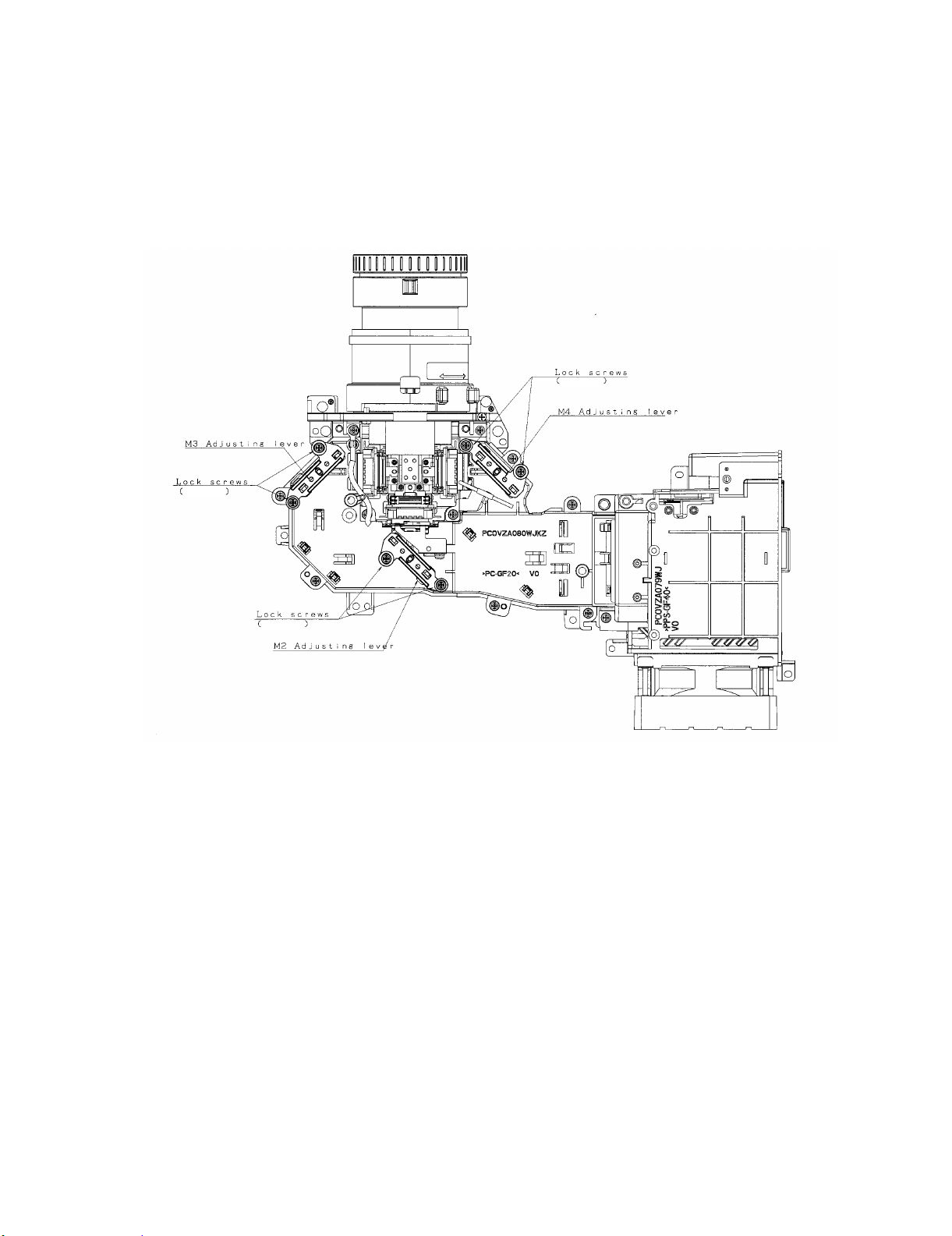
2. Adjusting the mirrors
This adjustment is needed when any of the optical parts of the optical mechanism has been replaced.
1. Disconnect the flat cables from all the LCD panels.
2. Light up the lamp.
3. Project a white-light image and check to see if there is any color tint in any direction. If any, use the M2, M4 and M5
adjusting levers.
4. Loosen the adjusting lever lock screws, make adjustments, and tighten up the lock screws.
Black
Black
Black
3. Correcting color irregularities on white-only screen when replacing the lamp
If color irregularities are found at the right and left on a white-only screen after replacing the lamp, it is necessary to
readjust the optical axis of the new lamp. Take the following steps.
1. Open the lamp cover and loosen the screws A and B at the top of the lamp.
2. Using a screwdriver or the like, move the lever D in the arrow direction.
3. Temporarily fix the screws A and B, close the lamp cover, and check the white-only screen again for color
irregularities.
4. Repeat the above steps 1 and 2 until there will be no color irregularities. Now tighten up the screws A and B.
5. Finally secure the lamp cover back in position.
3 – 2
Page 23
4. Replacing the prism holder unit
1. Remove the two lock screws, and take the prism holder unit out of the optical unit.
2. Replace the prism holder unit with new one. Take the above step 1 in reverse order.
NOTE: Even if just one of the LCD panels is defective, it is necessary to replace the entire prism unit. Do not replace
just the defective LCD panel only. Under the present circumstances, please do not touch the display part of
LCD.
XG-C330X/C430X
Optical unit
Prism holder unit lock screws
R-LCD panel
G-LCD panel
B-LCD panel
3 – 3
Page 24
XG-C330X/C430X
XG-C330X
CHAPTER 4. ELECTRICAL ADJUSTMENT
Service Manual
[1] PW software rewriting procedure
1. Prepare before rewriting.
1. Please prepare one RS232C cross cable and conversion cable.
Connect the conversion cable to the Projector, and it connects with a RS232C cross cable.
Connect opposite side to the serial port of personal computer.
2. Open the filter cover of the bottom cabinet and insert the LEAF SW JIG:PSPAZB245WJKZ.
Projector will be rewriting mode.
LEAF SW JIG:PSPAZB245WJKZ
If you don’t have LEAF SW JIG, open the top cabinet and select S2701 of main PWB to “WRITE” side.
Projector will be rewriting mode.
4 – 1
Page 25
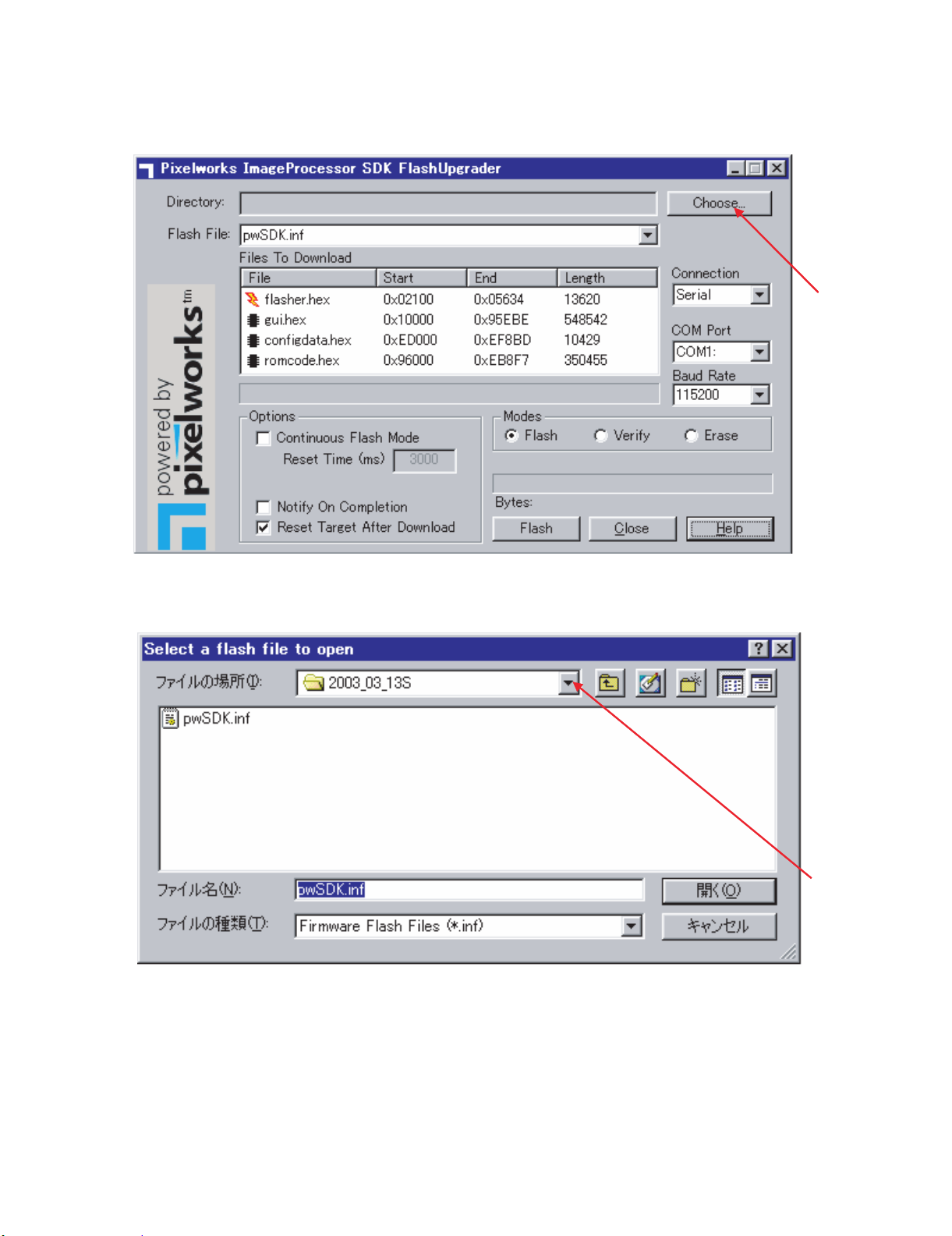
2. How to rewrite the software.
1. Projector software rewriting will be done with the Flash Up grader.
2. Unpack the software file.
3. Double-click on the "FlashUpgrader.exe ", so below window will be displayed on PC.
XG-C330X/C430X
4. Click on the “Choose” button.
Then, below window will be displayed on PC.
4 – 2
Page 26
XG-C330X/C430X
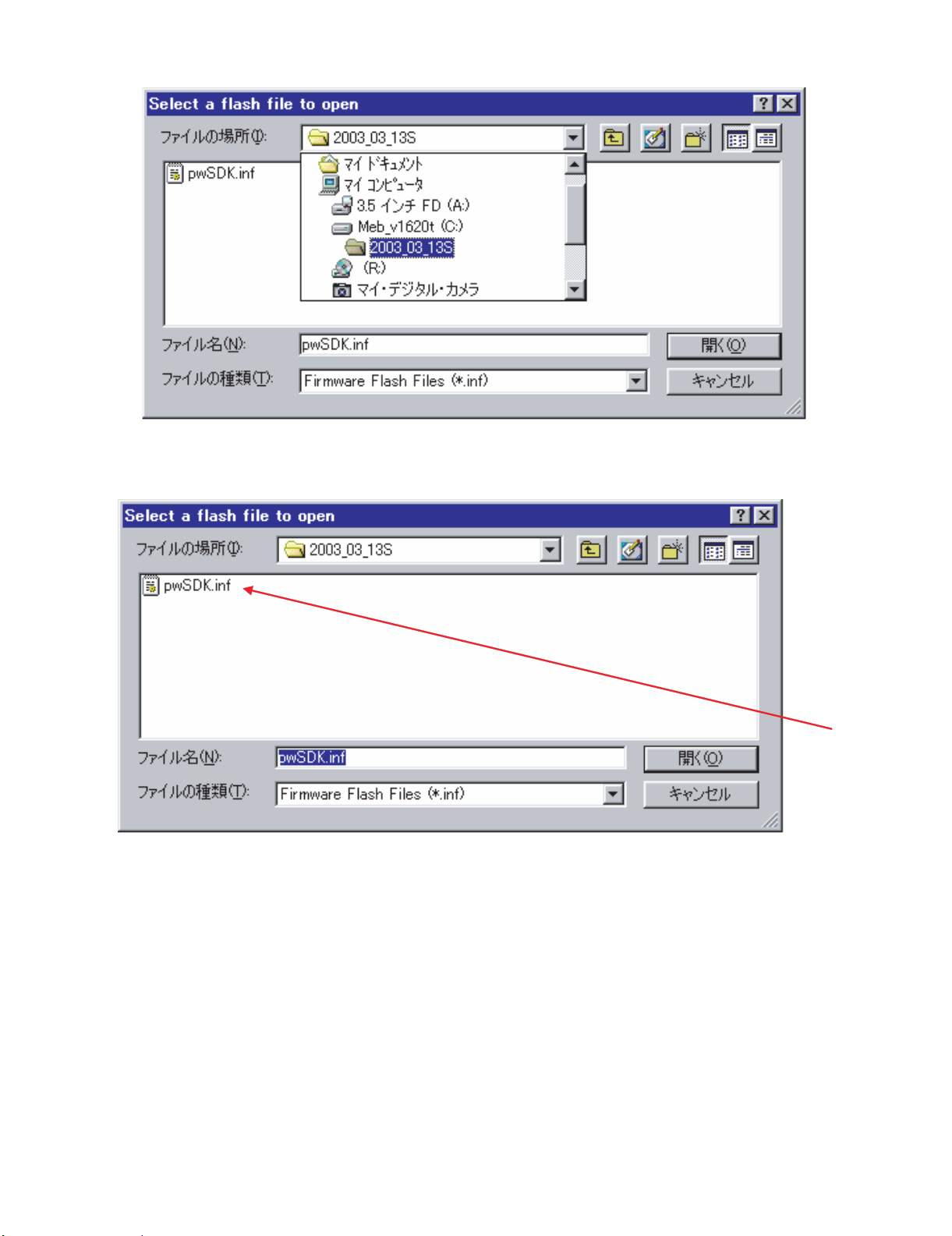
5. Clock on the above position and select the latest software
If you mistook the folder, please select the unpacked folder.
6. There is file named " pwSDK.inf " in this folder.
4 – 3
Page 27
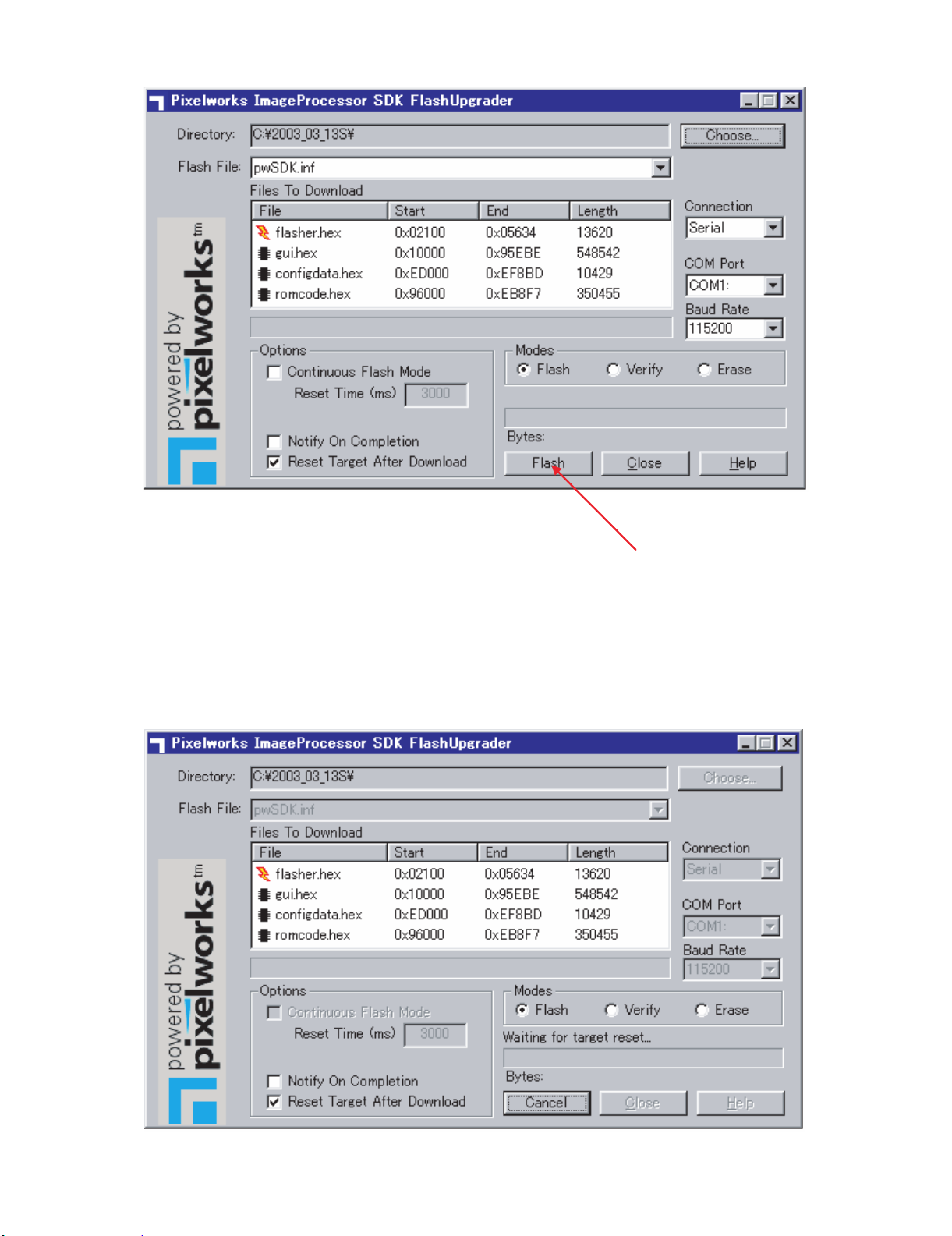
7. Double-click on the "pwSDK.inf".
XG-C330X/C430X
Note:
Options: Continuous Flash Mode; Do not put check point.
Notify On Completion; Do not put check point.
Reset Target After download; Put the check point.
Modes: Put the check point in “Flash”.
8. Click on the “Flash” button.
Then, below image will be appeared.
Now, preparation is completed.
4 – 4
Page 28
XG-C330X/C430X
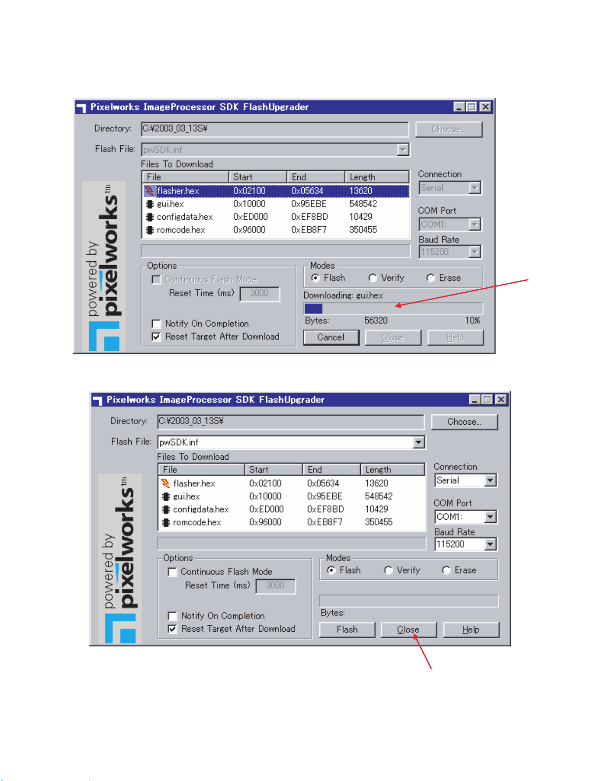
9. Next, connect the AC cord of the projector and software rewriting will start automatically.
If the gauge is not started, please check the “LEAF SW JIG” or “Write SW”.
Rewriting times are about 3 or 4 minutes.
Do not disconnect the AC cord by at this time.
Below window is under writing.
And below window will appear after software rewriting is completed.
Please click on “Close “ and software rewriting is finished.
10.Remove the LEAF SW JIG : PSPAZB245WJKZ and attach the filter cover.
Or select S2701 of main PWB to “NORMAL” side and attach the top cabinet.
Projector will be Normal mode(Non-writing mode)
4 – 5
Page 29
XG-C330X/C430X
3. Rewriting of the model name
1. Rewriting of the Model name will be done with the Tera Term.
2. Send the following command.
“MF1_0000” for XG-C430X
“MF1_0001” for XG-C330X
3. Remove the AC cord
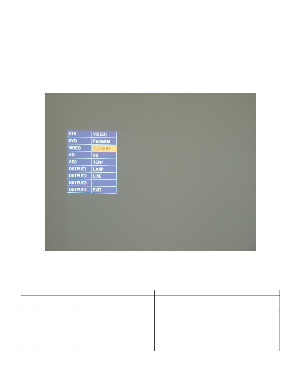
4. Confirmation of version.
1. Enter the “factory mode”,
With the menu not displayed, press the “ENTER”, “ENTER”, “VOL+”, “VOL-”, “ENTER”, “ENTER” and “MENU” keys on the projector
2. Below image is appeared and select “VERSION”.
Latest version will be appered.
[2] ELCTRICAL ADJUSTMENT
1. ELECTROCAL ADJUSTMENT (1)
No. Adjustment Item Adjustment Conditions Adjustment Procedures
1 EEPROM initialization 1) Turn on the power (the lamp turns on)
and perform aging for 15 minutes.
2 R-bright check
Contrast adjustment
(manual or automatic)
1) Input the white/black wind pattern signal of amplitude level 96% (0.67 Vpp)/
0% of XGA60Hz to COMPUTER1.
2) Select the following.
Group: AD
Adjustment item: R-Bright
R-Contrast
(Process gamma linkage)
1) Perform the following setting.
Press S6501 to enter the process mode, and execute SS2 of the
SS menu.
1) Check the fixed value.
R-Bright: 63
2) Observe the chromaticity of 96% white wind pattern portion using
CA100.
3) On the screen where bit dropouts occur, raise the R-Contrast
value. Adjust to the point where black to bright red bit dropouts
occur and the x value changes by 30/1000 or more.
4 – 6
Page 30
XG-C330X/C430X
White-white (2)
Amplitude (1)
No. Adjustment Item Adjustment Conditions Adjustment Procedures
3 G-bright check
Contrast adjustment
(manual or automatic)
4 B-bright check
Contrast adjustment
(manual or automatic)
5DTV
R-bright check
Contrast adjustment
(manual or automatic)
6DTV
G-bright check
Contrast adjustment
(manual or automatic)
7DTV
B-bright check
Contrast adjustment
(manual or automatic)
8 Black level/amplitude
adjustment of LCD
panel input signal
1) Input the white/black wind pattern signal of amplitude level 96% (0.67 Vpp)/
0% of XGA60Hz to COMPUTER1.
2) Select the following.
Group: AD
Adjustment item: G-Bright
G-Contrast
(Process gamma linkage)
1) Input the white/black wind pattern signal of amplitude level 96% (0.67 Vpp)/
0% of XGA60Hz to COMPUTER1.
2) Select the following.
Group: AD
Adjustment item: B-Bright
B-Contrast
(Process gamma linkage)
1) Input the white/black wind pattern signal of amplitude level 100% (0.7 Vpp)/
0% of 480P to COMPUTER1.
2) Select the following.
Group: AD2
Adjustment item: R-Bright2
R-Contrast2
(Process gamma linkage)
1) Input the white/black wind pattern signal of amplitude level 100% (0.7 Vpp)/
0% of 480P to COMPUTER1.
2) Select the following.
Group: AD2
Adjustment item: G-Bright2
G-Contrast2
(Process gamma linkage)
1) Input the white/black wind pattern signal of amplitude level 100% (0.7 Vpp)/
0% of 480P to COMPUTER1.
2) Select the following.
Group: AD2
Adjustment item: B-Bright2
B-Contrast2
(Process gamma linkage)
1) Select the following.
Group: OUTPUT 1
Adjustment item: G1-BLK
G1-GAIN
R:R1-BLK
R1-GAIN
B:B1-BLK
B1-GAIN
2) Check that the white pattern for process adjustment is displayed.
3) Connect a synchroscope to 2P of
(P1401).
4) For red and blue, connect to (P14011P) and (P1401-3P) respectively.
1) Check the fixed value.
G-Bright: 63
2) Observe the chromaticity of 96% white wind pattern portion using
CA100.
3) On the screen where bit dropouts occur, raise the G-Contrast
value. Adjust to the point where black to bright green bit dropouts
occur and the y value changes by 30/1000 or more.
1) Check the fixed value.
B-Bright: 63
2) Observe the chromaticity of 96% white wind pattern portion using
CA100.
3) On the screen where bit dropouts occur, raise the B-Contrast
value. Adjust to the point where black to bright blue bit dropouts
occur and the y value changes by 30/1000 or more.
1) Check the fixed value.
R-Bright2: 63
2) Observe the chromaticity of 100% white wind pattern portion using
CA100.
3) On the screen where bit dropouts occur, raise the R-Contrast2
value. Adjust to the point where black to bright red bit dropouts
occur and the x value changes by 30/1000 or more.
1) Check the fixed value.
G-Bright2: 63
2) Observe the chromaticity of 100% white wind pattern portion using
CA100.
3) On the screen where bit dropouts occur, raise the G-Contrast2
value. Adjust to the point where black to bright green bit dropouts
occur and the y value changes by 30/1000 or more.
1) Check the fixed value.
B-Bright2: 63
2) Observe the chromaticity of 100% white wind pattern portion using
CA100.
3) On the screen where bit dropouts occur, raise the B-Contrast2
value. Adjust to the point where black to bright blue bit dropouts
occur and the y value changes by 30/1000 or more.
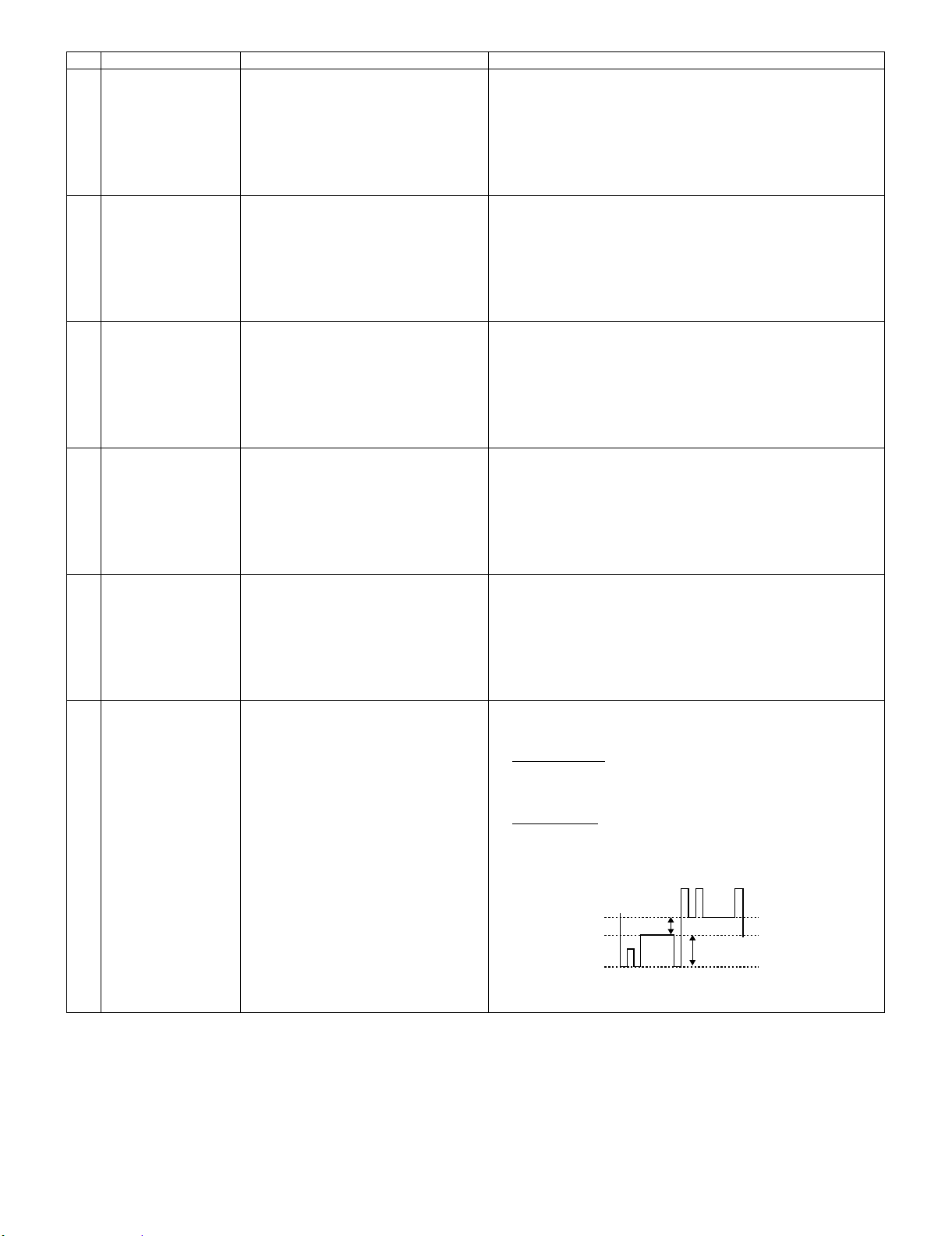
1) Select G1-GAIN, and adjust the signal amplitude as follows using
the operation SW or button on the remote control (see figure (1)
below).
4.6 Vpp
2) Select G1-BLK, and adjust the white-white level as follows using
the operation SW or button on the remote control (see figure (2)
below).
0.5 Vpp
3) Adjust red and blue in the same way.
(G waveform diagram of process pattern)
± 0.05 V
± 0.1 V
* The part defining the amplitude to the waveform is the same for both
R and B.
4 – 7
Page 31

No. Adjustment Item Adjustment Conditions Adjustment Procedures
9 Sample-hold pulse
delay amount adjustment
10 RGB counter voltage
adjustment
11 RGB white balance
adjustment
12 sRGB white balance
adjustment
13 Auto keystone initial-
ization
1) Input the black signal of XGA mode.
2) Select the following.
Group: OUTPUT3
Adjustment item: ENBR-DLY
G: ENBG-DLY
B: ENBB-DLY
1) Input the counter voltage adjustment
signal. (XGA)
2) Select the following.
Group: OUTPUT1
Adjustment item: R-COM
G-COM
B-COM
R-COM2
G-COM2
B-COM2
1) Input the RGB 50% gray signal.
(XGA60Hz)
2) Select the following.
Group: OUTPUT1
Adjustment item: R1-BLK (R)
B1-BLK (B)
1) Input the RGB 50% gray signal.
2) Select the following.
Group: OUTPUT1
Adjustment item: S-G1-BLK
S-B1-BLK
1) Select the following.
Group: LINE
Adjustment item: Calibration
1) Check the blur and ghost of characters of OUTPUT3.
2) Raise the ENBR-DLY value until pre-ghost appears on the left of
characters of OSD.
3) When the value is reduced by 1 to 2 points, pre-ghost disappears.
Set to the value reduced by 3 from the value where pre-ghost disappears.
(Set to 16 in the following case: When the ENBR-DLY value is 20,
pre-ghost appears; when it is 19, pre-ghost disappears.)
4) Adjust green and blue in the same way.
NOTE: EPSON panels may vary by 1 to 2 points from lot to lot. To
improve the ghost quality, perform this adjustment.
1) Adjust flicker using the operation SW or button on the remote control so that it becomes minimum.
2) When flicker appears on the screen unevenly, adjust the center
area considering the whole balance.
1) 1. Adjust R1-BLK and B1-BLK so that the following chromaticity
values are obtained in the middle of the screen using CL200.
x = 294 ± 5, y = 327 ± 5
1) Adjust S-G1-BLK and S-B1-BLK so that the following chromaticity
values are obtained in the middle of the screen using CL200.
x = 322 ± 5, y = 341 ± 5
1) With the set placed on a level surface, press the ENTER key and
check that K-Sensor value is 0 ± 3 (125 - 3).
Check that keystone is caused by tilting the unit.
XG-C330X/C430X
14 Model name writing 1) Write the model name with RS232C
command.
15 Tracking check 1) Input the RGB 10-step gray scale sig-
nal (inversion on top and bottom).
2) Select the following.
Group: OUTPUT3
Adjustment item: GAMMA
16 Auto color shading
correction
1) Perform the auto color shading correction using the color shading correction
system (ccdc).
1) C430: MF_10000 (default)
C330: MF_10001
1) Check the lower gradation tracking.
When it is improper, optimize the GAMMA value.
1: Default (normal)
2: Red and blue down
3: Red and blue up
NOTE: When changing the GAMMA value, readjust the white bal-
ance.
1) Check that remarkable color shading is not found on the screen.
2. Cautions for 3D color shading correction/adjustment
The following measurement and adjustment must be performed under the same conditions using the following:
• Dark room (Block out stray light.)
• Diffuse reflection (mat type) screen
The setting of the projector must be performed under the following conditions:
• Power save disabled (to keep the lamp stable during measurement)
• Auto search canceled (to fix to INPUT1)
• RGB mode of the input terminal COMPUTER1 (component mode canceled - just to be sure)
1. System setting (“Setting -” System setting””)
Condition setting for C330/C430
System option
Simultaneous writing of 3D correction value: No (not checked)
Char transmission interval: 0 ms
Binary interval: 2 ms
Creation of correction value by linear correction factor: No (not checked)
Number of image captures (during adjustment or measurement): Twice
4 – 8
Page 32

XG-C330X/C430X
System option
Number of image captures (during teaching): 4 times
2. Teaching
Basically, teaching should be measured only once from model to model. However, if the optical characteristics of the set are changed significantly,
it is necessary to reset the conditions according to changes and to perform remeasurement.
Measurement method of correction factor
1) Determine the standard set of C330/C430. Each one unit (n units)
2) Switch the set to the RGB mode of the input terminal COMPUTER1.
3) Execute teaching of the standard set under the following conditions.
Condition setting for C330/C430
Model name: Enter the model name newly.
Resolution: 1024 x S768
Binary interval: 2 ms
Correction value, X direction: 33
Correction value, Y direction: 25
Number of correction bits: 8
Adjustment value, minimum: -32
Adjustment value, center: 0
Adjustment value, maximum: 32
Number of teachings: 5
Teaching interval: 32
Brightness variation direction by adjustment value: Brightness UP by increasing the adjustment value (checked)
Adjustment point: 3D (checked)
Adjustment point (Test pattern display level)
Tone 0: 44%
Tone 1: 64%
Adjustment color: Adjustment with RGB (checked)
3. Color shading correction (adjustment)
Condition setting for C330/C430
TG system (selected)
Tone 0 (checked)
Tone 1 (checked)
Other tones are not checked.
Correction setting
Tone 7: Default
Tone 6: Default
Tone 5: Default
Tone 4: Default
Tone 3: Default
Tone 2: Default
Tone 1: Correction by correction factor
Tone 0: Correction by correction factor
Correction method
Select the model name created in the section (2) and perform color shading correction/adjustment.
If the set has significantly different optical characteristics from the standard or shows color shading or line dropouts, execute teaching and adjust it
using the correction factor.
3. ELECTROCAL ADJUSTMENT (2)
No. Adjustment Item Adjustment Conditions Adjustment Procedures
17 DTV bright/contrast
adjustment
18 DTV tint adjustmen 1) Select the following.
19 TV color saturation
adjustment
1) Select the following.
Group: DTV
Adjustment item: Contrast
Bright
Group: DTV
Adjustment item: Tint
1) Select the following.
Group: DTV
Adjustment item: Color
1) Check the fixed values.
Contrast: 10
Bright: 40
1) Check the fixed value.
Tint: 5
1) Check the fixed value.
Color: 12
4 – 9
Page 33

No. Adjustment Item Adjustment Conditions Adjustment Procedures
20 DVD bright/contrast
adjustment
21 DVD tint adjustment 1) Select the following.
22 DVD color saturation
adjustment
23 Video bright/contrast
adjustment
24 Video tint adjustment 1) Select the following.
25 Video color saturation
adjustment
26 RGB tone reproduction
adjustment
1) 1. Select the following.
Group: DVD
Adjustment item: Contrast
Bright
Group: DVD
Adjustment item: Tint
1) Select the following.
Group: DVD
Adjustment item: Color
1) Select the following.
Group: VIDEO
Adjustment item: Contrast
Bright
Group: VIDEO
Adjustment item: N-Tint
P-Tint
S-Tint
1) Select the following.
Group: VIDEO
Adjustment item: N-Color
P- Color
S- Color
1) Input the SMPTE pattern.
2) Group: OUTPUT1
Adjustment item: G1-BLK
1) Check the fixed values.
Contrast: 9
Bright: 40
1) Check the fixed value.
Tint: 5
1) Check the fixed value.
Color: 12
1) Check the fixed values.
Contrast: 8
Bright: 40
1) Check the fixed values.
N-Tint: 5
P-Tint: 5
S-Tint: 5
1) Check the fixed values.
N-Color: 6
P- Color: 6
S- Color: 6
1) Check that white 100% and 95% tones are visible.
2) If visibility of the white tones is different, fine adjust G1-BLK.
XG-C330X/C430X
27 White balance check RGB input, sRGB input, component input,
video input, S-video input
28 Vertical stripe level
check
29 Checking of off-timer
performance
30 Checking of ther-
mistor performance
31 Automatic sync opera-
tion
32 Monitor out check 1) Input the video and audio signals to the
33 RS232C operation
check
34 USB operation check 1) Connect to a PC with an USB cable. 1) Check that forward/reverse operation is enabled on the PC screen
35 LAN operation check 1) Connect to a PC with a LAN cable. 1) Check that communication is possible.
36 Remote control check 1) Check the wired remote operation.
1) Receive the RGB gray scale signal. 1) It must be better than the vertical stripe boundary sample.
1) Heat the thermistor with a hair dryer. 1) Make sure the temperature is displayed.
1) Receive the phase checking pattern
signal.
COMPUTER1 and COMPUTER2 terminals.
2) Connect another monitor to the monitor
out terminal.
3) Connect a speaker with a built-in amplifier to the audio out terminal.
1) Connect the unit and a PC with the
RS232C cable.
2) Check the remote control operation.
1) Check that there is no disturbance in the white balance using a
monitor.
1) Select OFF in the process mode.
Make sure that the off-timer starts with 5-minute display, counts
down 1minute for 1second, and turns off when 0minute is displayed.
1) Make sure that Clock, Phase, H-POS and V-POS can be automatically adjusted in the VGA/S-VGA/XGA mode.
1) Check that image selected with the projector is displayed on
another monitor connected to monitor out terminal and sound is
heard from the speaker connected to the audio out terminal.
1) Send a command from the PC, and check it functions correctly.
using the remote control.
1) Check that the wired remote control terminal is activated.
2) Check the remote control operation.
4 – 10
Page 34

XG-C330X/C430X
No. Adjustment Item Adjustment Conditions Adjustment Procedures
37 Model name check 1) Send “TNAM 1” and “MNRD 1”h with
RS232C command.
38 Delivery settings 1) Make the following settings.
1) Check that the appropriate model name is displayed correctly.
4. Adjustment mode process menu
Adjustment mode process menu
Group Sub Group Subject
Adjust DTV image DTV Contrast
Tint
Color
Sharpness
Bright
B-DRIVE
R-DRIVE
Adjust DVD image DVD Contrast
Tint
Color
Sharpness
Bright
B-DRIVE
R-DRIVE
Adjust Video image VIDEO Contrast
N-Tint
P-Tint
S-Tint
N-Color
P-Color
S-Color
Sharpness
Bright
B-DRIVE
R-DRIVE
Adjust PC image AD R-Bright
G-Bright
B-Bright
R-Contrast
G-Contrast
B-Contrast
Adjust PC image AD2 R-Bright2
G-Bright2
B-Bright2
R-Contrast2
G-Contrast2
Destination Process Remote control
adjustment adjustment
USA SS4 Factory setting at 4
Others SS3 Factory setting at 3
4 – 11
Page 35

Group Sub Group Subject
B-Contrast2
Adjust RGB image OUTPUT1 R1-BLK
R1-GAIN
G1-BLK
G1-GAIN
B1-BLK
B1-GAIN
TGR-BLK
TGR-GAIN
TGG-BLK
TGG-GAIN
TGB-BLK
TGB-GAIN
R-COM
G-COM
B-COM
R-COM2
G-COM2
B-COM2
COM-LEVEL
S-R1-BLK
S-G-BLK
S-B-BLK
Adjust Panel OUTPUT2 LC-SW
LC-HPOS-R
RLV1
RLV1
RLV2
RLV3
RLV1
LC-HPOS-G
GLV1
GLV1
GLV2
GLV3
LC-HPOS-B
BLV1
BLV1
BLV2
BLV3
BLV3
Adjust Panel OUTPUT3 ENBR-DLY
ENBG-DLY
ENBB-DLY
ENBXR-PH
ENBXG-PH
ENBXB-PH
ENBX-WIDTH
DGC-SW
DGCJ-R
DGCJ-G
DGCJ-B
CC
GAMMA
Adjust Panel OUTPUT4 FPRR-H
FPRR-L
FPRG-H
FPRG-L
FPRB-H
FPRB-L
FPR-ST
FPR-END
Adjust Video image VIDEO1 N-Contrast
P-Contrast
XG-C330X/C430X
4 – 12
Page 36

XG-C330X/C430X
Group Sub Group Subject
S-Contrast
Color
NT3.58Delay
NT4.43Delay
PALDelay
SECAMDelay
Adjust Video image PEDESTAL R-Bright
G-Bright
B-Bright
R-Contrast
G-Contrast
B-Contrast
Version Check VERSION Build
BootCode
Config
RomCode
GUI
LAN
Initial setting SS SS2
SS3 EU
SS4 US
SS5 JPN
SS6 CHIN
Sensor check TEMP Temp1
Te mp 2
Te mp 3
Lamp Timer check LAMP Current time
History 1
History 2
History 3
History 4
TOTAL TIME
Process mode LINE OFF
LED CHECK
Calibration
K-Sensor
V-S ize
Fan-mode
Nfan-Normal
4 – 13
Page 37

XG-C330X
CHAPTER 5. TROUBLE SHOOTING TABLE
Service Manual
[1] TROUBLE SHOOTING TABLE
Checking the basic operation
XG-C330X/C430X
Does the power LED light up or
flash in red or green?
YES
Does the set function with its keys
or the remote controller?
YES
Lamp does not turn on or it turns
off in a short time.
NO
Colors are not display correctly. YES Has P1101, P1201 or P1301
NO
Are RGB and component input
displayed normally?
NO Has P1704 come off or is it
loose?
NO Go to "Main PWB check".
YES Go to "Lamp fails to light-up".
come off or is it loose?
NO Go to "RGB and component sig-
nal check".
YES Fully insert the connector.
YES Fully insert the connector.
YES
Is VIDEO input displayed normally?
YES
Is S-VIDEO input displayed nor-
mally?
YES
Does the LAN function? NO Go to “checking the LAN”.
YES
END
NO Go to "VIDEO input check".
NO Go to "S-VIDEO input check".
5 – 1
Page 38

XG-C330X/C430X
Main PWB check
Is 6 V applied to TL1711, 13 V to
TL1712 and 17V to TL1727?
YES
Is approx. 6 V applied to TL1709? NO Check IC1710 and peripheral circuits.
YES
Is 1.5 V applied to TL1705? NO Check IC1706 and peripheral circuits.
YES
Is 3.3 V applied to TL1706? NO Check IC1704 and peripheral circuits.
YES
Is 2.5 V applied to TL1704? NO Check IC1702 and peripheral circuits.
YES
Is 5 V applied to TL1708? NO Check IC1707 and peripheral circuits.
YES
Is 3.3 V applied to TL1703? NO Check IC1708 and peripheral circuits.
NO Go to "Power supply ballast PWB check".
YES
Is 15.5 V applied to TL1707? NO Check IC1705 and peripheral circuits.
YES
Is5 V applied to TL1701? NO Check IC1701 and peripheral circuits.
YES
Is 3.3V applied to TL1702? NO Check IC1703 and peripheral circuits.
YES
Is 5.4V applied to TL2075? NO Check IC2001 and peripheral circuits.
YES
Is 3.3 V applied to pin(2) of S2701? NO Check that it is set to the NORMAL side.
Or remove S2701.
YES
Is rectangular wave of 14.318 MHz
sent to X2003 pin(3)?
YES
Is rectangular wave of 48 MHz sent
to X2201 pin(3)?
NO Check X2003 and peripheral circuits.
NO Check X2201 and peripheral circuits.
YES
Check IC2001, IC2201, IC2202 and
peripheral circuits.
5 – 2
Page 39

Lamp fails to light-up
XG-C330X/C430X
Turn on the power switch.Is
dischargeing sound heard
from lamp?
NO
Is the ballast cooling fan
runnning?
YES
Is the DC voltage of 380V
applied to pin(1) of P702 connector?
YES
Is LOW LEVEL voltage
applied between pins(3) and
(4) of Main's P1702 connec-
tor?
YES YES
Replace the ballast.
YES
NO
NO
NO
Is the lamp out of socket?
NO
Repalce the lamp.
Check the power supply circuits.
Check the power supply circuits.
Is the P1702 connector disconnect?
Reconnect it into socket correctly.
YES
NO
Reconnect the lamp into
socket.
Check the microprocessor
and its peripheral circuits.
5 – 3
Page 40

XG-C330X/C430X
Checking the power unit
There is no voltage output at P703?
YES
Is AC voltage (90-264V) applied
acress the P801 connector?
YES
Is AC voltage (90-264V) applied
acress the P701 connector?
YES
Is the fuse F801 open?
NO
Is the Bimetal SW open?
NO
Replace the Inlet unit.
NO
NO
NO
YES
YES
Check the Main PWB
unit.
Check the P801 or AC
Cord.
Is the resistor R729
open?
NO
Replace power unit?
Replace the F801.
Push the red button of
the bimetal.
YES
Replace R729.
5 – 4
Page 41

RGB and component signal
check
Send component signal or
RGB signal of 1080i (or 720P)
from INPUT 1 or INPUT 2.
Select INPUT 1 or INPUT 2
using keys on the main unit or
the remote control.
XG-C330X/C430X
Are picture signals sent to
TL2502, TL2503, and
TL2504?
YES
Is 3.3V applied to TL1702? NO Check IC1703 and peripheral cir-
YES
Is 3.3V applied to TL1703? NO Check IC1708 and peripheral cir-
YES
Check IC2505 and peripheral
circuits.
NO Check IC2403 and peripheral cir-
cuits .
cuits.
cuits.
5 – 5
Page 42

XG-C330X/C430X
S-VIDEO (INPUT 3)
check
Send S-Video signal
(color signal) from
INPUT 3. Select INPUT
3 using keys on the
main unit or the remote
control.
Is image displayed in
black and white?
NO YES
Is S-VIDEO signal (Y)
sent to C3139?
YES YES
Is 5 V applied to
TL1701?
YES Check S-VIDEO ter-
minal and pin(43) of
IC3103.
NO Check S-VIDEO ter-
minal and peripheral
circuits of IC3103.
NO Check IC1701 and
peripheral circuits.
VIDEO (INPUT 4)
check
Send VIDEO signal from
INPUT 4. Use buttons
on the main unit or the
remote control to select
INPUT 4.
Is VIDEO signal sent to
C3137?
Is 5 V applied to
TL1701?
Check IC3103 and
peripheral circuits.
NO Check VIDEO termi-
nal and peripheral circuits of Q3104 and
Q3107.
NO Check IC1701 and
peripheral circuits.
YES
Check IC3103 and
peripheral circuits.
5 – 6
Page 43

Checking the LAN
LAN communication is disabled even
though connecting the control PC with a
LAN cable. The LINK LED (green) does not
light up.
Are the connection of connecting cable and
the settings of IP address, sub-net address
and default gateway correct?
YES
XG-C330X/C430X
NO Check the connecting cable and LAN settings. If the LAN
settings are unknown, contact the network administrator.
If the network settings cannot be saved, replace IC6708
(EEP ROM) as it may be defective.
Note: When IC6708 (EEP ROM) is replaced, the MAC
address returns to default. Refer to "Resetting after replacing IC6708 (EEP ROM)" to reset.
Are the network device (e.g. Hub) between
the control PC and XG-C430X and cable
normal?
YES
When data is sent from the control PC, do
pins (30) and (31) of IC8201 (PHY receiver)
receive signals?
YES
Check the PHY receiver IC8201 and the
peripheral circuits of the microprocessor
IC8001.
NO Repair defective parts in the network.
NO Check the peripheral circuit of J8201 (RJ-45 jack with built-
in transformer).
5 – 7
Page 44

XG-C330X/C430X
XG-C330X
CHAPTER 6. BLOCK DIAGRAM/OVERALL WIRING DIAGRAM
Service Manual
[1] BLOCK DIAGRAM
SYSTEM BLOCK DIAGRAM
,
+
*
)
(
'
&
%
$
#
6 – 1
Page 45

XG-C330X/C430X
6 – 2
Page 46

XG-C330X/C430X
[2] OVERALL WIRING DIAGRAM
OVERALL WIRING DIAGRAM
,
+
*
)
(
'
&
%
$
#
6 – 3
Page 47

XG-C330X/C430X
6 – 4
Page 48

XG-C330X
XG-C330X
CHAPTER 7. PRINTED WIRING BOARD
[1] MAIN Unit
Service Manual
7 – 1
Page 49

XG-C330X
7 – 2
Page 50

XG-C330X
C
C
C1232
C
,
عMAIN Unit (Chip SIDE-A)
+
*
)
(
'
&
%
$
#
FB2414
R2406
C2403
R2417
R2419
R2434
D2419
IC2301
D2421
R2322
C2312
Q2303
R1764
R1763
IC1714
D1714
R1762
C1760
C1762
C1738
R1761
R1760
R1759
IC1711
D1710
C1737
R1757
C1725
C1723
FB1701
L1701
C1303 C1304
C1305
C1307
R1311
R1312
C1310
R1319
R1320
C1333
C1721
D1705
C1705
C1710
C1711
C1302
IC1301
R1315
C1330
C1318C1319
IC1302
FB1303
C1324
C1321
C1323
R1316
C1761
R1758
D2422 D2423
R2321
C2415
R1765
R2613
R2611
R2609
C1739
IC2901
R2904
C2903
R2903
C1719
IC1708
C1717
R1722
R1711
R1709
C1301
C1331
FB1301
C1328
C1306
C1308
C1309
R1313R1314
C1332
FB1302
C1320
C1322
C1317
FB2411
R2404
SC 2701
R2027
R2452
R2447
R2448
R1712
C1216
C1215
C1214
C1213
C1212
C1211
C1209
C2622
R1723
R1720
FB2405
R2310
C2301
C2303
C2306
R2320
R2431
IC2203
C1208
R2306
C2405
D2304
R2425
R2427
D2417
R2332
C2410
C2409
C2411
FB2415
C2510
C2630
R2628
Q2705
R2713
R2714
D2202
R2212
C2219
R2230
Q2003
R2234
Q2004
R2238
FB2202
C1231
C1207
C1229
C1205
C1203
FB1201
IC1201
C1228
R1201
R1202
R1203
R1205
R1206
C1206
R2401
C2404
R2421
R2423
R2429
D2415
IC2403
C2414
C2607
R2509
Q2503
IC2502
C2623
Q2001
C1210
R1212
R1219
C1714
R1211
R1317
R1318
L1301
C1326
C1325
C2308
R2650
C2702
D2201
SC 2702
Q2002
C2213
C1204
R2304
IC2303
C2008
C1202
FB2302
C2633
C2632
IC2603
IC2604
IC2605
D2701
C1201
IC2606 IC2607
FB2702
C2706
C1225
C2307
C2701
C2710
FB2301
FB2303
D2307
D2305
C2631
R2631
R2633
R2638
R2640
R2645
R2647
IC2701
R2701
R2702
R2703
R2704
FB2701
R2709
R2711
Q2703
C2709
C2305
C2708
C2704
R2303
R2319
R2305
R2309
D2302
D2306
R2329
C2314
R2630
Q2606Q2607Q2608
R2635
R2637
R2642
R2643
R2649
D2702
R2710
C2705
C1227
C2703
C2406
D2308
R2420
R2433
D2420
IC2302
R2317
Q2304
C2313
R2326
R2327
Q2305
R2328
R2325
R2629
C2628
R2634
R2636
R2641
C1702
R2644
R2648
C1749
C2707
Q2701
R2705R2706
D2203 D2204
Q2702
R2707
R2708
C1226
L1201
FB2412
FB2413
R2403
R2405
R2418
R2318
C2311
C2546
R1749
R1706
D1703
IC1703
C1429
C1430
C1431
FB1403
IC1403
D1401
R1217
C2503
IC2202
R2430
C2218
R1436
R2424
D2416
C1425
FB2406
R2402
C2407
R2422
C1706
R1713
R1428
FB1202
C12
C1223C1224
R1216
7 – 3
Page 51

C2546
R1706
1401
IC1703
XG-C330X
R2902
C2901
FB2412
R2403
R1749
D1703
C1430
C2503
IC2202
R2430
C2218
R1436
R2424
D2416
C1425
FB2406
C2302
C2304
FB2305
FB2306
C2539
C2536
C2537
C2532
R2532
IC2505
R2534
R2018
R1426 R1427
C2309
R2307
R2311
R2323
FB2304
D2301
C2541
C2543
R2535
C2540
R2536
IC2003
R2019
IC1401
FB2504
R2537
R2538
R2539R2540
C2545
FB2502
R2039
C2038
R2050
R2049
R2023
R2037
R2038
R2024
C2310
R2308
R2312
R2529
R2324
C2408
D2303
C2524
C2520
C2525
C2521
C2522
C2526
C2523
R2527
C2529
C2527
R2530
C2530
R2526
C2535
R2528
C2531
FB2505
R2015
R2001
R2003R2004 R2005
R2007
R2016
C1401
R1417
R1420R1421
R2426
R2428
D2418
C2533
C1750
R2402
C2407
R2422
R2432
C2504
FB2506
C1706
R1713
R1714
R2011
R2012
R2013
R2014
R2235
C1402
R1428
R1418R1419
R2046
R2048
FB2802
R2821R2822R2823
R2830
R2801
R1429
L2801
L2802
L2803
L2804
D2803 D2804
C2804
C2806
C2808
IC2805
R2828R2829
C2039
R2036
R2032
R2033
R2034
R2035
R2043
R1425
FB2001
C2041
FB2006
C2040
FB2005
R2056
C1428
R1401R1402R1403R1404R1405
R1408
FB2804
C1716
R2825
C1708
C2810
R1704
C2807
FB2803
C2802
D2802
R2804
R2805
R2803
C2816
Q2801
Q2802
C2817
Q2803
C1709
C1704
C1707
C1701
C1703
R1705
C1724
R2806
IC2801
C2801
R2802
C1715
C1713
IC1704
C1712
C1747
C1718
C2902
R2901
D1707
IC1706
IC1707
C1729
R1730
C1722
D1708
L1702
C1743
C1744
D1704
R1721
FB1202
C1223C1224
R1216
FB1203
C1232
C1233
R1220
C1221
R1415
IC1202
C1220
C1230
C1218
R1416
R1118
C1121
C1123
C1222
C1124
R1116
C1127
C1122
C1103
C1105
L1101
C1126
R1117
C1107
R1111
R1112
R1119
C1110
C1125
R1414
C1133
C1102
IC1102
R1412R1413
R1120
C1130
C1119
C1118
C1120
C1101
C1104
R1101
R1102
R1103
IC1101
C1113C1114C1115C1116
R1105
R1106
C1108
C1112
R1746
Q1703
C1735
Q1704
IC1709
Q1705
R1741
C1733
R1734 R 1735
R1733
FB1709
FB1703
FB1710
7 – 4
C1728
R1739
R1740
C1748
FB1708
Page 52

XG-C330X
,
عMAIN Unit (SIDE-B)
+
*
)
(
'
&
%
$
#
7 – 5
Page 53

XG-C330X
7 – 6
Page 54

XG-C330X
4
6
C
R1435
C
R
,
عMAIN Unit (Chip SIDE-B)
+
*
)
(
'
&
%
R2302
Q2302
R231
C2016
C2026
C2023
C2028
Q1401
C2034
FB2003
R2010
R1433
C1409
C1410
C1412
C1414
C1417C1418
C1419
R2065
C2538
FB2004
C2035
C2003
C2004
C2027
C1426
R2009
FB2007
R231
R2002
R
R
1219
R2813
C2812
C2811
C2814
R2812
C2813
R2809
C1731
R1732
IC1710
C1727
C1734
R1744
C1732
R1731
R1716
R1743
R1742
Q1701 Q1702
R1710
FB1702
R1707
R1715
C1730
C1726
R1717
R1718
C1720
R1729
R1703
P1705
FB1716
FB1715
IC2804
R1719
C1753
IC1712
R2808
IC2802
C1752
R1724
R1725
R1726
C2803
C1742
R1727 R 1728
Q1706 Q1707
FB1705
D1712
FB1713
C2805
FB2805
R1708
R1752
R2826
R2827
C2819
C2820
R2824
C2809
FB2806
C2029
D1702
IC1702
C1741
C1745
IC1701
R1701
C1746
D1701
D1706
IC1705
C1751
FB1707
D1711
D2805
R1745
R1736
FB1706
R1755
R1702
R1751
C1736
R1753
D1709
R2815
R2816
R2818
R2817
R2820
C2815
R2819
C2818
C2821
C2032 C2033
C2037
C2036
R2030
R2028
R2029
R2044
R2055
R2047
C1427
FB1402
C1432
R1407
R1406
R1410 R1411
P1706
R2057
R2045
C1408
C1411
C1413
C1415
C1416
C2012
C2022
C2013
C2025
C2020
C2014
C2030
R2053
FB1103
C2015
C1420
C2544
C2542
R2064
X2002
C2010
C2009
C2011
C2018
C2021
C2019
C2017
C2031
C2024
C2044
R2025
R2022
R2058
R2006
C1406
C1407
C1403
C1404
C1405
C1421
C1422
C1423
C1424
R1430
R1409
P1702
$
#
C1131
C1132
FB1102
FB1101
C1117
C1106
C1109
C1129
C1128
R1113
C1111
R1104
R1107
R1108
R1109
R1110
R1114 R 1115
SC 1101
7 – 7
Page 55

XG-C330X
C1406
C1424
1409
R2064
X2002
C2044
C1407
C2018
C2021
C2031
R2006
C2016
C2026
C2023
C2028
Q1401
R2302
C2034
FB2003
R2010
R1433
C1409
C1410
C1412
C1414
C1417
C1419
R2065
C2538
FB2004
C2035
C2003
C2004
D2406
D2412
Q2706
D2410
FB2403
FB2407
R2411
R2455
C2603
R2652
C2613
Q2601
R2604
C2612
Q2602
R2605
C2610
R2606
Q2603
C2609
R1302
R1305
Q2704
R1301
R2608
C2614
C2616
C2617
R1306
C1311
R1303
C1312
C1758
C1754
C1755
C2627
R2712
C1313
FB2601
R1750
R1747 R 1748
C1314
C1740
FB1717
FB1714
IC1713
D1713
C1315
R1304
R1307
R1308
R1309
R1310
R1738
R1754
C1316
C1756
FB1704
C1757
C1329
S2701
R1737
P1701
D2404
D2402
R2412
IC2401
IC2601
C2601
C2604
R2622
C2625
R2617R2618
R2231
Q2401
Q2402
R2621
C2201
C2214
D2408
FB2404
FB2408
R2457
R2409
R2407
D2413
C2401
R2415
R2458
R2435
R2439
R2440
C2620
R2203
R1207
R2623
R1210
R1209
R2639
R1218
R2453
R1208
R2449
R2450
R2451
C2602
C2605
C2606
R2632
R2646
IC2602
R2619
R2651
R2208
R2209
C2203
R2229
R2210
R2211
C2206
C2208
R2216
R2218
C2211
SC 1801
R1213R1214R1215
C1217
C2507
C2515
SC 2202
SC 2201
C2007
D2409
D2411
FB2401
FB2409
R2456
R2454
R2413
D2425
R2501
FL2501
R2511
C2506
C2509
R2512
R2510
R2514
R2515
R2518
IC2501
R2517
R2525
C2517
R2521
R2522
R2523
R2524
R2627
R2206
R2228
C2204
R2060
C2205
R2220
C2006
IC2002
R2020
IC2001
C2005
C2207
R2021
R2222
R2213
R2215
C2209
R2221
X2201
FB2201
C2210
R2219
SC 1201
R2205
R2438
C2413
IC2409
D2424
R2626
R2202
C2629
R2620
R2201
Q2605
R2204
R2301
Q2301
R2315
R2313
C2412
IC2405
Q2403
R2437
IC2407
R2436
R2601
C2608
R2602
R2603
C2611
R2607
C2615
R2610
R2624
R2615
C2618
Q2604
R2612
R2614
C2619
R2616
C2621
C2624
C2626
R2625
C2202
IC2201
R2233
R2223
C2215C2216
R2026
R1204
P1401
D2403
D2405
D2407
D2401
FB2402
FB2410
C2042
X2001
R2416
D2414
R2503
R2507
C2502
R2533
R2520
FB2501
C2518
R2408
Q2502
R2410
R2414
C2402
IC2402
R2508
Q2501
R2502
R2506
R2505
C2501
C2505
R2504
C2519
C2511
C2512
R2513
R2516
C2508
C2513
R2531
R2519
C2514
C2516
R1439
Q2302
R2316
R2314
FB2007
R2068
X2003
R2069
C2043
R2017
C2002
C2001
R2008
FB2002
R2002
C2027
R2009
R1437
R1438
R1435
C1426
R1422
R1431
R1423
R1424
C1219
SC 1101
SC 1301
C1327
7 – 8
FB1711
FB1712
P1703
Page 56

XG-C330X
[2] TERMINAL Unit
عTERMINAL Unit (SIDE-A)
,
+
*
)
(
'
&
%
$
#
7 – 9
Page 57

عTERMINAL Unit (Chip SIDE-A)
,
+
FB8205
R3501
FB3502
FB3501
C3501
D8205
D8206
D8202
R8237
R8230
R8211
R8213
FB8202
C8211
R8216
IC8201
C8218
C8220
C8217
D8203
R8236
C8210
FB8201
R8232
C8219
C8213
C8208
FB8504
XG-C330X
FB8203
*
Q8503
R8510
R8509
C8501
R8505
D8501 D8502
)
D3553
FB3552
R3551
R3552
FB3303
FB3302
C3304
C3301
FB3301
C3401
C3402
D3552
(
'
&
C3403
FB3107
C3312
C3101
%
$
FB3108
C3102
FB3105
FB3106
C3103
R3110
R3109
C3104
FB3104
D3307
D3303
Q3304
Q3305
R3130
C3132
D3304
R8507
R8506
Q3303
R3311
C3316
C3314
C3313
R3313
Q3306
C3328
C3112
R8512
IC8501
D3305
D3101
C8503
R3312
C3323
C3317
C3133
L3101
R3125
C8504
D3301 C3325
IC8502
R8513
R8033
R3119
R8514
R3332
R3335
Q3307
Q8502
R8036
R8026
C8027
C3326
Q3309
R8037
R8025
R8027
C8029
C3165
R3334
R8051
R8053
C8506
R8052
R8054 R8055
R8008
IC8004
C8028
IC8005
C3164
C3157
IC3104
C3152
C3153
C3154
C3155
Q3308
C3159
R3333
R3151
R3152
R3336
C3163
R3106
R3329
C3188
R3326
Q3313
C3193
C3192
C3190
C3137
C3189
C3147
C3179
C3173
IC8001
C3172
R8050
IC3105
C3146
IC3103
C3168
C3145
C8030
C3194
R3185
R3184
C3187
C3183C3184
R3177
C3185
C3182
C3178
R3179
R3108
R8032
R8046
R8047
R8070FB3551
C3181
R8048
C8035
FL3103
FL3104
FB8005
R3337
C3329
IC3305
R3338
R3339
R3340
R3341 R3342
SC3301SC3302
R3343
R3344
#
7 – 10
Page 58

XG-C330X
عTERMINAL Unit (SIDE-B)
,
+
*
)
(
'
&
%
$
#
7 – 11
Page 59

عTERMINAL Unit (Chip SIDE-B)
,
+
C8209
XG-C330X
D8204
C8202
R8215
R8210
C8203
R8209
C8205
R8214
C8212
R8212
C8204
R8234
R8231
X8201
R8235
R8221
C8206
R8233
R3303
C3122
C3144
C8006
R3503
C3319
R8516
R8515
R8511
R8508
Q8501
R8503
R8059
C8040
IC8006
C8039
C8038
Q8001
X8002
C8033
R8005
X8001
D3302
R3314
L3103
R3144
R3103
Q3312
R3105
R3330
C3322
IC3304
C3327
C3321
R3305
IC3303
IC3301
C3134
Q3107
R3102
R3122
Q3104
R3118
R8501
R8502
FB8502
C8505
C8502
D8503
FB8501
D8504
D3554
D3551
C3308
Q3302
R3301
R3308
C3307
R3309
Q3301
R3307
C3315
D3402
FB3402
D3403
FB3403
D3401
R3401
R3310
FB3401
R3402
FB3404
D3404
R3331
C3324
R3304
R3324
IC3302
FB3405
R3403
C3320
R3328
D3405
R3346
Q3311
R3327
R3306
R3316
R3323
R3320
C3310
R3319
R3315
D3306
C3318
R3318
C3311
R3317
R3321 R3322
C3309
FB3102
FB3103
FB3101
R3325
R3104
R3101
*
R8030
R8057
C8005
R8039
IC8003
R8040
)
(
R8041
C8019
R8006
R8007
IC8008
R8001
R8068
C8041
C8020
R8045
R8031
'
R3345
&
%
$
R3302
C3151
R3172
R3166
R3180
C3174
C3180
R3164
Q3116
R3173
R3174
R3161
R3167
C3142
C3158
C3160
Q3117
R3162
R3165
R3163
C3175
R3183
Q3122
Q3121
R3182
L3104
R3107
C8009
C8014
C8018
C3149
R3141
R8043
C3143
C8003
R8042
C8001
C8022
C3138
C3166
C8004
C8011
C8015
C8002
C8016
C8026
C8025
R8012
C8032
C8031
C8021
C8023
C8024
R8028
D3102
C3139
R3140
C3169
R8013
D3103
R3138
Q3108
C3167
R3142
C8034
R8016
C8017
R8004
L3102
C3150
C3148
C3161
Q3101
Q3310
L3107
R3137
C3177
L3106
L3105
#
S8001
7 – 12
Page 60

XG-C330X
[3] KEY Unit
عKEY Unit (SIDE-A)
,
+
*
)
(
'
&
%
$
#
7 – 13
Page 61

XG-C330X
7 – 14
Page 62

XG-C330X
C6506
7
9
1
عKEY Unit (Chip SIDE-A)
,
+
*
IC6502
R6737
R6744
R6723
R6751
D6705
R6730
C6702
C6724
FB 6702
P6703
FB 6703
C6716
C6521
R6527
R6528
FB 6508
P6503
FB 6509
S6507
C6709
IC6702
C6723
C6520
IC6710
FB 6507
S6514
C6516C6517
)
R6748
R6756
R6735
S6501
R6741
IC6707
C6714
C650
C650
C651
C6508
C6510
(
S6510S6511
S6502
'
S6512
S6509
S6506
&
S6508
%
S6504
S6503
S6505
$
C6717
FB 6704
FB 6705
C6721
FB 6712
R6524
Q6502
R6525
D6505
D6503
R6523
Q6501
D6504
#
FB 6713
P6708
P6704
7 – 15
Page 63

XG-C330X
R6517
IC6502
FB 6507
C6520
S6514
C6516C6517
C6723
C6724
IC6710
R6748
R6756
R6735
R6741
IC6707
C6714
C6507
C6509
C6511
C6506
S6501
C6508
C6510
FB6505
C6515
C6519
R6520
FB 6506
R6761
D6716
R6713
D6710
C6503
C6502
C6701
D6714
FB 6502
D6702
R6727
R6724
R6753
R6731
IC6703
Q6703
D6712
D6703
Q6704
IC6701
R6708R6709
D6711
D6713
D6706
C6728
Q6701
Q6702
R6710
C6703
R6780
C6727
Q6705
D6701
D6715
C6707
D6717
R6738
R6745
C6710
FB 6501
P6501
D6506
IC6503
D6501
C6522
C6512
D6502
R6508
R6729
IC6302
C6306
R6309
R6310
R6726
R6725
C6704
C6705
C6706
D6303
C6303
C6302
C6307
R6316
C6708
IC6708
IC6501
R6513
R6754
R6739R6740
R6750 R6752
R6755
Q6302
IC6303
C6309
C6518
C6514
C6513
D6707
D6708
D6709
Q6301
IC6704
R6720
IC6705
R6728
IC6706
C6304
IC6301
C6305
R6768
C6715
R6732R6733R6734
R6746R6747
R6743
C6711
C6712
C6713
TH6502
D6301
D6302
P6709
FB6707
C6718
FB6706
FB6709
C6719
FB6708
FB6711
C6720
FB6710
C6505
FB 6504
FB 6503
C6504
P6502P6701
P6705P6706
P6707
C6717
FB 6704
FB 6705
P6704
7 – 16
FB 6701
P6702
R6736
FB 6719
IC6712
IC6711
IC6709
R6774
P6301
Page 64

XG-C330X
,
#
$
%
&
'
(
)
*
+
عKEY Unit (SIDE-B)
7 – 17
Page 65

XG-C330X
7 – 18
Page 66

XG-C330X
,
#
$
%
&
'
(
)
*
+
عKEY Unit (Chip SIDE-B)
R6504
R6322
C6523
R6511
R6321
R6507
R6503
R6530
R6529
R6749
R6701
R6757
R6766
R6702
C6729
R6742
R6758
R6759
R6760
R6516
R6512
R6519
R6521
R6518
R6717 R6718
R6715
R6704
R6706R 6707
R6773
R6703
R6772
R6712 R6714
R6705
R6778
R6711
R6721
R6762
R6763
R6764R 6765
R6771
R6770
R6769
R6719
R6312
R6305
R6307
R6306
FB 6716
R6779
FB 6717
C6722
R6311
R6320
R6318
R6304
R6303
R6302
R6317
R6319
R6308
R6314
R6315
C6308
R6313
R6716
R6514
R
R6506
R6510
P6801
FB 6720
C6726
FB6715
FB6714
R6775
R6301
FB 6302
R6776
C6301
FB 6301
R6767
R6777
C6725
FB 6718
R6501
C6501
R6502
R6505
R6509
7 – 19
Page 67

XG-C330X
R6516
R6512
R6519
R6521
R6518
R6762
R6763
R6764R 6765
R6722
D6704
9
R6514 R6515
R6506
R6505
R6510
R6509
Q6503
R6526
R6522
7 – 20
Page 68

XG-C330X
[4] POWER Unit
عPOWER Unit (SIDE-A)
,
+
*
)
(
'
&
%
$
#
7 – 21
Page 69

عPOWER Unit (SIDE-B)
,
+
*
XG-C330X
)
(
'
&
%
$
#
7 – 22
Page 70

XG-C330X
عPOWER Unit (Chip SIDE-B)
,
R764 R765
R727 R728
R724
R725
IC705
C730
R723
R757
R726
+
FB704
R768
C731
D724
C724
R766R767
C727
*
R712
R756
R755
C722
R753
Q721
R754
Q722
R760
R748
R761
Q720
R718
D717
C743
IC702
C739
)
D707
(
D708
R711
D725
'
D723
C751
D712D713
R758 R759
R742 R743
FB701
D718D719
FB702
R744R745
R746R747
R741
R749
Q702
R720
R750
R721
R751
Q703
R763
R752
R739
R735
R734
D705
D710
R738
C719
R713
R714R715
D709
C718
&
D722
C715
%
$
R733
D704
C733
D714
R732
C709
IC707
R707
R717
C703
R719
R722
C734
R731
C735
R730
C717
#
7 – 23
Page 71

[5] INLET Unit
,
عINLET Unit (SIDE-A)
+
*
XG-C330X
)
(
'
عINLET Unit (SIDE-B)
&
%
$
#
7 – 24
Page 72

XG-C330X
[6] R/C Unit
عR/C Unit (SIDE-A)
,
+
*
عR/C Unit (Chip SIDE-A)
)
(
عR/C Unit (SIDE-B)
'
&
%
عR/C Unit (Chip SIDE-B)
C5591
$
P5591
#
R 5592
C5592
R5591
7 – 25
Page 73

[7] CONDENCER Unit
عCONDENCER Unit (SIDE-A)
,
+
*
XG-C330X
)
عCONDENCER Unit (SIDE-B)
(
'
&
عCONDENCER Unit (Chip SIDE-B)
%
R9501 R9502 R9503
$
R9507
R9506
#
R9504R9505
7 – 26
Page 74

XG-C330X
MEMO
7 – 27
Page 75

XG-C330X
CHAPTER 8. SCHEMATIC DIAGRAM
[1] DESCRIPTION OF SCHEMATIC DIAGRAM
1. VOLTAGE MEASUREMENT CONDITION:
1. Voltages at test points are measured at the supply voltage of AC
220V. Signals are fed by a color bar signal generator for servicing
purpose and the above voltages are measured with a 20k ohm/V
tester.
2. WAVEFORM MEASUREMENT CONDITION:
1. Waveforms at test points are observed at the supply voltage of AC
220V. Signals are fed by a color bar signal generator for servicing
purpose.
3. INDICATION OF RESISTOR & CAPACITOR:
RESISTOR
1. he unit of resistance “Ω” is omitted.
(K=kΩ=1000 Ω, M=MΩ).
2. All resistors are ± 5%, unless otherwise noted.
(J=± 5%, F= ± 1%, D= ± 0.5%)
3. All resistors are 1/10W, unless otherwise noted.
4. All resistors are Carbon type, unless otherwise noted.
XG-C330X/C430X
Service Manual
: Solid : Cement
C
S
: Oxide Film : Special
N
: Metal Coating
CAPACITOR
1. All capacitors are μF, unless otherwise noted.
(P=pF=μμF).
2. All capacitors are 50V, unless otherwise noted.
3. All capacitors are Ceramic type, unless otherwise noted.
(ML): Mylar (TA): Tantalum
(PF): Polypro Film (ST): Styrol
CAUTION:
This circuit diagram is original one, therefore there may be a
slight difference from yours.
W
T
SAFETY NOTES:
1. DISCONNECT THE AC PLUG FROM THE AC
OUTLET BEFORE REPLACING PARTS.
2. SEMICONDUCTOR HEAT SINKS SHOULD BE
REGARDED AS POTENTIAL SHOCK HAZARDS
WHEN THE CHASSIS IS OPERATING.
IMPORTANT SAFETY NOTICE:
PARTS MARKED WITH “ ” ( ) ARE
IMPORTANT FOR MAINTAINING THE SAFETY OF THE
SET. BE SURE TO REPLACE THESE PARTS WITH
SPECIFIED ONES FOR MAINTAINING THE SAFETY AND
PERFORMANCE OF THE SET.
8 – 1
Page 76

XG-C330X/C430X
[2] SCHEMATIC DIAGRAM
عMAIN Unit-1/11
,
+
*
)
(
'
&
%
$
#
8 – 2
Page 77

XG-C330X/C430X
8 – 3
Page 78

XG-C330X/C430X
,
#
$
%
&
'
(
)
*
+
عMAIN Unit-2/11
8 – 4
Page 79

XG-C330X/C430X
8 – 5
Page 80

XG-C330X/C430X
عMAIN Unit-3/11
,
+
*
)
(
'
&
%
$
#
8 – 6
Page 81

XG-C330X/C430X
8 – 7
Page 82

XG-C330X/C430X
عMAIN Unit-4/11
,
+
*
)
(
'
&
%
$
#
8 – 8
Page 83

XG-C330X/C430X
8 – 9
Page 84

XG-C330X/C430X
عMAIN Unit-5/11
,
+
*
)
(
'
&
%
$
#
8 – 10
Page 85

XG-C330X/C430X
8 – 11
Page 86

XG-C330X/C430X
عNAIN Unit-6/11
,
+
*
)
(
'
&
%
$
#
8 – 12
Page 87

XG-C330X/C430X
8 – 13
Page 88

XG-C330X/C430X
عNAIN Unit-7/11
,
+
*
)
(
'
&
%
$
#
8 – 14
Page 89

XG-C330X/C430X
8 – 15
Page 90

XG-C330X/C430X
عMAIN Unit-8/11
,
+
*
)
(
'
&
%
$
#
8 – 16
Page 91

XG-C330X/C430X
8 – 17
Page 92

XG-C330X/C430X
عMAIN Unit-9/11
,
+
*
)
(
'
&
%
$
#
8 – 18
Page 93

XG-C330X/C430X
8 – 19
Page 94

XG-C330X/C430X
عMAIN Unit-10/11
,
+
*
)
(
'
&
%
$
#
8 – 20
Page 95

XG-C330X/C430X
8 – 21
Page 96

XG-C330X/C430X
عMAIN Unit-11/11
,
+
*
)
(
'
&
%
$
#
8 – 22
Page 97

XG-C330X/C430X
8 – 23
Page 98

XG-C330X/C430X
عTERMINAL Unit-1/4
,
+
*
)
(
'
&
%
$
#
8 – 24
Page 99

XG-C330X/C430X
8 – 25
Page 100

XG-C330X/C430X
عTERMINAL Unit-2/4
,
+
*
)
(
'
&
%
$
#
8 – 26
 Loading...