

Page 1
XA-705
I
1 XA-71 O,XA-720
. -: SHARF’
XA-705
XA-710
I
L
@mq$3q I
7rw
XA-720
-
?
<
,
\.9
SERVICE MANUAL
S78T6XA-705//
/vus/ PROFESSIONAL
VIDEO CASSETT
XA-705
I
MODELS XA-710, XA-720
b
In the interests of user-safety (Required by safety regulations
in some countries) the set should be restored to its original.
condition and only parts identical to those specified be used.
SERIES
E RECORDER
1
Page
1. GENERAL INFORMATION . . . . . . . . . . . . . . . . . . . . . . . . . . . . . . 4
I-1 FEATURES . . . . . . . ..‘....................................... 4
1-2 SPECIFICATIONS . . . . . . . . . . . . . . . . . . . . . . . . . . . . . . . . . . . . . 4
l-3 LOCATION OF MAJOR COMPONENTS
AND CONTROL . . . . . . . . . . . . . . . . . . . . . . . . . . . . . . . . . . . . . . . . .
2. DISASSEMBLY AND REASSEMBLY m........,.... 6
2-1 DISASSEMBLY OF MAJOR BLOCKS . . . . . . . 6
2-2 DISASSEMBLING THE MECHANISM/
MAIN PWB ASSEMBLY . . . . . . . . . . . . . . . . . . . . . . . . . . . . . 7
2-3 CARES WHEN REASSEMBLING . . . . . . . . . . . . . . 8
3. FUNCTION OF MAJOR MECHANICAL
PARTS . . . . . . . . . . . . . . . . . . . . . ..~......................................
4. ADJUSTMENT, REPLACEMENT AND
ASSEMBLY OF MECHANICAL UNITS . . . . . . . . . . 11
4-l MECHANISM CONFIRMATION
ADJUSTMENT JIG . . . . . . . . . . . . . . . . . . . . . . . . . . . . . . . . . . 11
5. ELECTRICAL ADJUSTMENT . . . . . . . . . . . . . . . . . . . . . . . . 30
5-I ADJUSTMENT OF HEAD SWITCHING
POINT
. . . . . . . . . . . . . . . . . . . . . . . . . . . . . ..*.......................
31
5-2 ADJUSTMENT OF FV (False Vertical Sync)
OF STILL PICTURE . . . . . . . . . . . . . . . . . . . . . . . . . . . . . . . . .
5-3 CHECKING OF OFF TRACK . . . . . . . . . . . . . . . . 31
5-4 ADJUSTMENT OF SIF-INPUT LEVEL . . . . 32
5
9
5-5 ADJUSTMENT OF FILTER . . . . . ..e.............. 32
5-6 ADJUSTMENT OF STEREO VCO . . . . . . . . . . . 32
5-7 ADJUSTMENT OF STEREO
SEPARATION . . . . . . . . . . . . . . . . . . . . . . . . . . . . . . . . . . . . . . . . . . .
6. MECHANISM OPERATION FLOWCHART
AND TROUBLESHOOTING GUIDE . . . . . . . . . . . . . . 33
7. TROUBLESHOOTING . . . . . . . . ..*........................
8. BLOCK DIAGRAM . . . . . . . . . . . . . . . . . . . . . . . . . . . . . . . . . . . . . . . . . .
9. SCHEMATIC DIAGRAM . . . . . . . . . . . . . . . . . . . . . . . . . . . . . . . .
lO.PRINTED WIRING BOARD ASSEMBLIES . . . . 80
11 .PARTS LIST
12.PACKING OF THE SET
. . . . . . . . . . . . . . . . ..*.................................
. . . . . . . . . . . . . . . . . . . . . . . . . . . . . . .
Page
31
32
39
53
62
84
103
SHARP CORPORATION
This document has been published to be used for after
sales service only.
The contents are subject to change without notice.
Page 2
XA-705
XA-71 O,XA-720
IMPORTANT SERVICE NOTES
BEFORE RETURNING THE VIDEO
CASSETTE RECORDER
Before returning thevideo cassette recorder
to the user, perform the following safety
checks.
1. Inspect all lead dress to make certain that leads are
not pinched or that hardware is not lodged between
the chassis and other metal parts in the video cassette
recorder.
2. Inspect all protective devices such as non-metallic
control knobs, insulation materials, cabinet backs,
adjustment and compartment covers or shields, isolation resistor/capacitor networks, mechanical insulators and etc.
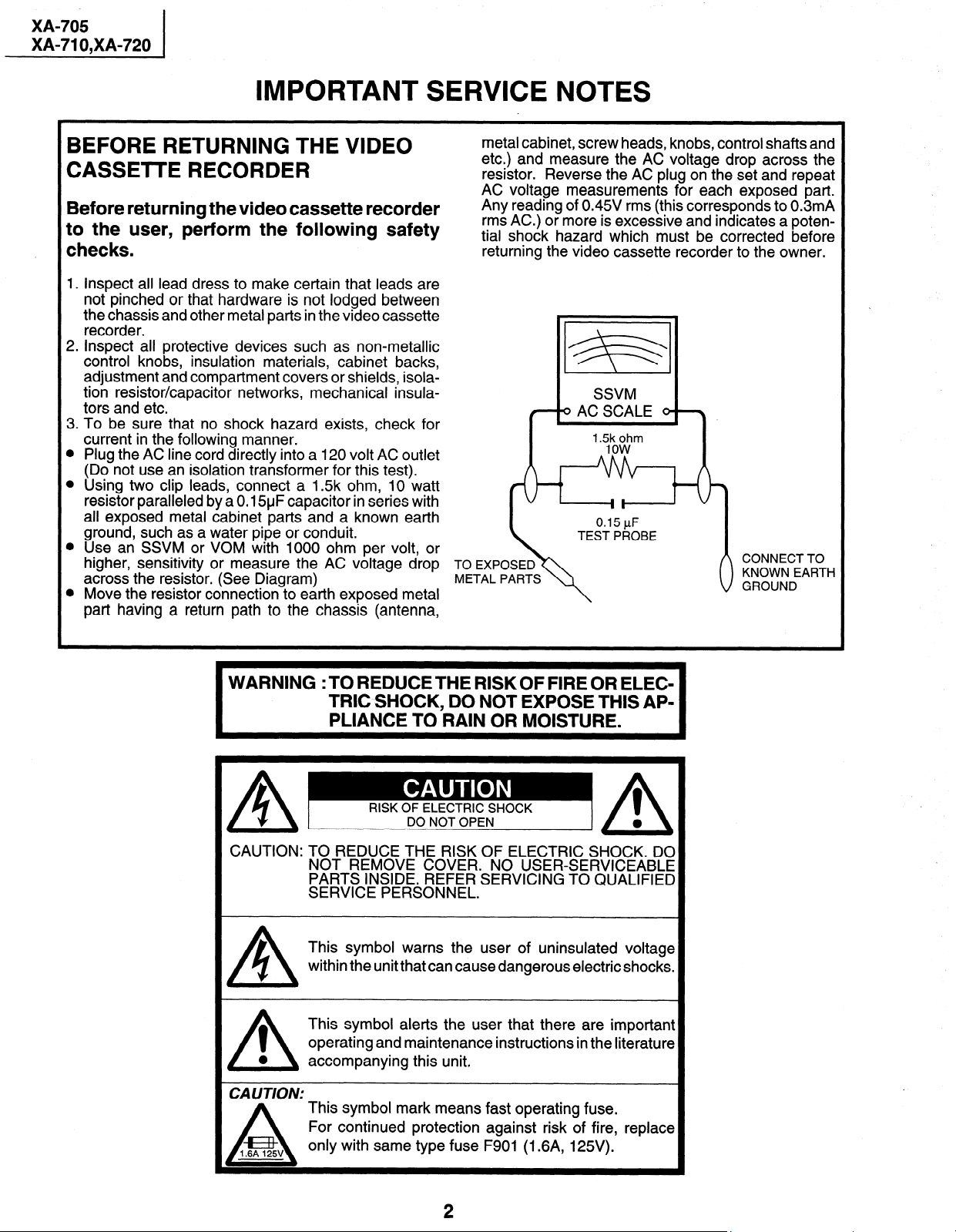
3. To be sure that no shock hazard exists, check for
current in the following manner.
l Plug the AC line cord directly into a 120 volt AC outlet
(Do not use an isolation transformer for this test).
l Using two clip leads, connect a 1.5k ohm, 10 watt
resistor paralleled by a 0.15yF capacitor in series with
all exposed metal cabinet parts and a known earth
ground, such as a water pipe or conduit.
l Use an SSVM or VOM with 1000 ohm per volt, or
higher, sensitivity or measure the AC voltage drop TO EXPOSED
across the resistor. (See Diagram)
l Move the resistor connection to earth exposed metal
part having a return path to the chassis (antenna,
metal cabinet, screw heads, knobs, control shafts and
etc.) and measure the AC voltage drop across the
resistor. Reverse the AC plug on the set and repeat
AC voltaae measurements for each exposed part.
Any readhg of 0.45V rms (this corresponds to 0.3mA
rms AC.) or more is excessive and indicates a potential shock hazard which must be corrected before
returning the video cassette recorder to the owner.
METAL PARTS
SSVM
( 9ACSCALE 9 \
/
’ m%t?m
\
WARNING :TO REDUCETHE RISKOF FIRE OR ELEC-
TRIC SHOCK, DO NOT EXPOSE THIS AP-
PLIANCE TO RAIN OR MOISTURE.
A
RISK OF ELECTRIC SHOCK
A-==-
CAUTION: TO REDUCE THE RISK OF ELECTRIC SHOCK. DO
A
1
0
/\
CAUTION:
1.6A 125v
A
NOT REMOVE COVER. NO USER-SERVICEABLE
PARTS INSIDE. REFER SERVICING TO QUALIFIED
SERVICE PERSONNEL.
This symbol warns the user of uninsulated voltage
within the unit that can cause dangerous electric shocks.
This symbol alerts the user that there are important
operating and maintenance instructions in the literature
accompanying this unit.
This symbol mark means fast operating fuse.
For continued protection against risk of fire, replace
only with same type fuse F901 (1.6A, 125V).
DO NOT OPEN
0
1
0
/\
2
Page 3
XA-705
XA-71 O,XA-720
PRECAUTIONS IN PART REPLACEMENT
When servicing the unit with power on, be carefwl to the section marked white all over.
This is the primary power circuit which is live.
When checking the soldering side in the tape travel mode, make sure first that the tape has been loaded and then turn
over the PWB with due care to the primary power circuit.
Make readjustment, if needed after replacement of part, with the mechanism and its PWB in position in the main frame.
Start and end sensors: Q701 and Q702
Insert the sensor’s projection deep into the upper hole of the holder. Referring to the PWB, fix the sensors tight
enough.
Photocoupler: IC901
Refer to the symbol on the PWB and the anode marking of the part.
Cam switches A and B: D708 and D709
Adjust the notch of the part to the white marker of the symbol on the PWB. Do not allow any looseness.
Take-up and supply sensors: D707 and D706
Be careful not to confuse the setting direction of the parts in reference to the symbols on the PWB. Do not allow
any looseness.
3
Page 4
XA-705
XA-71 O,XA-720
1 l GENERAL INFORMATION
l-1 FEATURES
Common Features
0
8 Hours of Recording / Playback (T-160)
0
181 ch Cable Ready With Frequency Synthesizer Tuner
0
CM Skip Search
0
Automatic Playback Function
0
Blue Screen 81 On Screen Setup Programming Function
0
Full Loading System
l
Simple Recording Timer
0
Tamper Proof Function
l
Automatic Tracking System
0
3-Language OSD
0
Sharp Super Picture
0
Instant Replay
l
Universal R/C
0
EZ Set Up
l
Automatic Daylight Saving-Time (DST) Adjustment
e
Quasi S-VHS Playback
l
1 Hour Back-up
1-2 SPECIFICATIONS
1) Recording system
Format:
Luminance Signal:
Chroma Signal:
Color System:
Number of Video Head:
Tape Speed:
2) Video signal
Input Level:
Output Level:
Signal to Noise Ratio:
Horizontal Resolution:
3) Audio signal
Input Level:
Output Level:
Frequency Response:
Signal to Noise Ratio:
Hi-Fi Dynamic Range:
Wow and Flutter:
4) Receiving channel
CATV:
Antenna Input Impedance:
5) Miscellaneous
Fast forward /Rewind Time:
Power Source:
Power Consumption:
Allowable Ambient Temperature:
Operating Humidity:
Dimensions:
Weight:
Accessories Included:
VHS NTSC Standard
FM recording
Low frequency converted direct recording
NTSC
4 PCS.
(SP) 33.35 mm/set
(LP) 16.67 mm/set (playback only)
(EP) 11.12 mm/set
0.5 - 2.0 Vp-p, 75 ohm unbalanced
1 .O Vp-p, 75 ohm unbalanced
45dB Min. (SP mode)
220 lines Min. (SP mode)
- 8 dBs (309 mVrms, 47k ohm Min.)
- 8 dBs (309 mVrms, 1 k ohm Max.)
80Hz - IOkHz (Linear), 20Hz - 20kHz (Hi-Fi) (at SP mode)
43dB (Linear) (at SP mode)
90dB (XA-720)
0.005% max. (XA-720)
VHF:
ch. 2 - 13
UHF:
ch. 14 - 69
ch. A8, A5 - W +84
75 ohm
Approximate 1 minute with T-120 cassette
120 V AC, 60 Hz
20 W at 12OV AC, 60Hz
5 to 40°C (41 to 104°F)
Less than 80% RH
XA-705: 360 (W) x 92 (H) x 269 (D) mm(14-3/16 x 3-5/8 x 10-I 9/32 inch)
XA-710: 360 (W) x 92 (H) x 276 (D) mm(l4-3/16 x 3-5/8 x 1 O-7/8 inch)
XA-720: 360 (W) x 92 (H) x 264 (D) mm(14-3/16 x 3-5/8 x lo-13/32 inch)
2.8 kg (6.0 Ibs)
75 ohm Coaxial Cable, Opetarion Manual, Timer Setting Card,
Infrared R/C Unit, Dry Battery (3 PCS.)
Only for XA-710, XA-720
l Cable Box Control
l Automatic Head Cleaning
l VCR Plus + Programming System
Only for XA-720
l Universal R/C with Light up
l Viewcam Dubbing
Note: Specifications are subject to change without notice.
4
Page 5
I
X
A0
w” al
D
XX
DD
44
I-
O
c)
P
-I
0
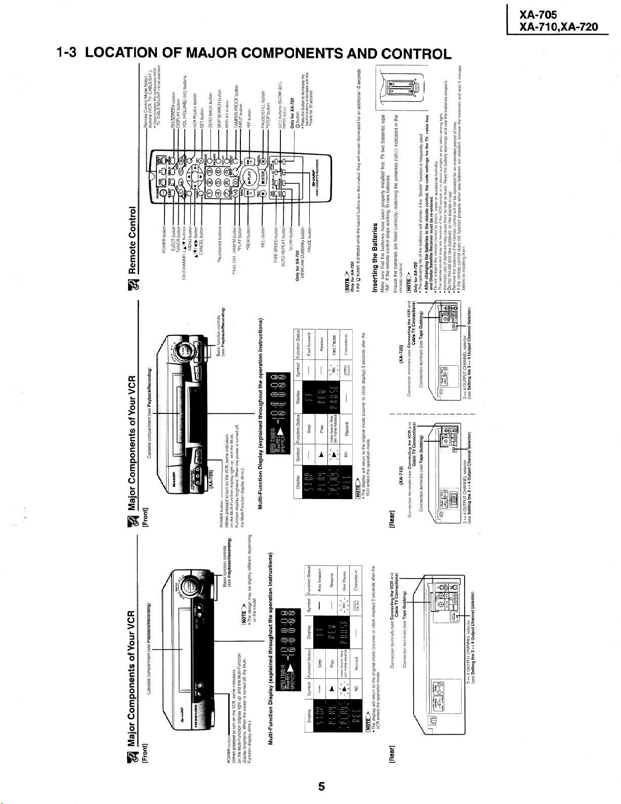
Remote Control Mode Select
buttons (VCR, TV, CABLE/SAT )
l Used to selecl the component (VCR.
Remote Control
a
TV CABLE BOX/SAT ) to be opera!ed
ON SCREEN button
DISPLAY button
VOL (VOLUME) O/O buttons
A/V buttons
CH (CHANNEL)
VCR PLUS+ button
SET button
ZERO BACK button
SKIP SEARCH button
REPLAY button
n controls
:k/Recording)
TAMPER PROOF button
*lOO. ENT /AM/PM button
INPUT button
*FF button
PAUSE/STILL button
*STOP button
TAPE SPEED button
O/O buttons (SLOW @X3.
DPSS &/a,)
AUTO REPEAT button
Only for XA-720
Q button
Only for XA-720
Symbol Function Statu
l Press the button to Illumlna:e the
VIEWCAM DUBBING button
backlll bultons (Indlcatecl with the
*mark) for 10 seconds
_ 1 I
Only for XA-720
If the 0 button IS pressed whrle the backlit buttons are Illumtnated. they WIII remarn illumlnated for an adddtonal 10 seconds
Inserting the Batteries
Make sure that the battenes have been properly Installed first. Fit two batteries type
“AA”. If the remote control stops worktng. fit new batteries.
remote control
INoTE)
On/y for XA-720
l The operating life of the batteries WIII shorten If the “Backlit” function IS frequently used
and Digital Satellite Receiver must be re-entered.
l After changing the batteries in the remote control, the code settings for the TV, cable box
Ensure the battenes are fitted correctly, matching the polarltles (O/e) indicated in the
l uo nor suoject the remote control to shock, water or excessive humidity
l The remote control may not function If the VCR sensor IS In direct sunllght or any other strong light
l Incorrect use of battenes may cause them to leak or burst Read the battery warnings and use the batteries properly
l Do not mix old and new battenes or mix brands 111 use
before re-tnstalling them
l Remove the batterlcs If the remote control wll not be operated for an extended penod of time
_ I‘ AL-^ ____L
- II LII~: relllute control does not function properly when new batteries are Installed. remove the battenes and watt 5 minutes
I
Cable TV Connections)
(XA-720)
Connection terminals (see Tape Dubbing)
Connectron terminals (see Connecting the VCR and
I I I I I I I
I I I I I
3 tf 4 OUTPUT CHANNEL selector 1 (see Setting the 3 +-+ 4 Output Channel Selector)
I
I
a Major Components of Your VCR
[Front]
Cassette compartment (see Playback/Recording)
Cassette compartment (see Playback/Recording)
I
Basic function controls
I
(see Playback/Recording)
on the model
l The design may be slightly different depending
INoTE)
Multi-Function Display (explained throughout the operation instructions)
Multi-Function Display (explained throughout the operation instructions)
Symbol Function Status Display
Display
Display Symbol Function Status
Function Status
Display Symbol
riimir)
Cable TV Connections)
(XA-710)
VCR enters the operation mode
l The display wtll return to the original mode (counter or clock display) 3 seconds after the
Connection terminals (see Tape Dubbitng)
Connection terminals (see Connecting the VCR and
[Rear]
3 tf 4 OUTPUT CHANNEL selector
(see Setting the 3 t+ 4 Output Channel Selector)
I
Cable TV Connections)
Connection terminals (see Tape Dubbing)
Connectlon terminals (see Connecting the VCR and
(see Setting the 3 cf 4 Output Channel Selector)
VCR enters the operation mode
l The display WIII return to the orIgInal mode (counter or clock drsplay) 3 seconds after the
m Major Components of Your VCR
[Front]
POWER button-
(When pressed to turn on the VCR. some lndrcators
on the Multi-Function display light up, and the Multl-Functron
display bnghtens When the power IS turned off, the Multl-
Function dlsplaj dims )
[Rear]
Page 6
XA-705
XA-71 O,XA-720
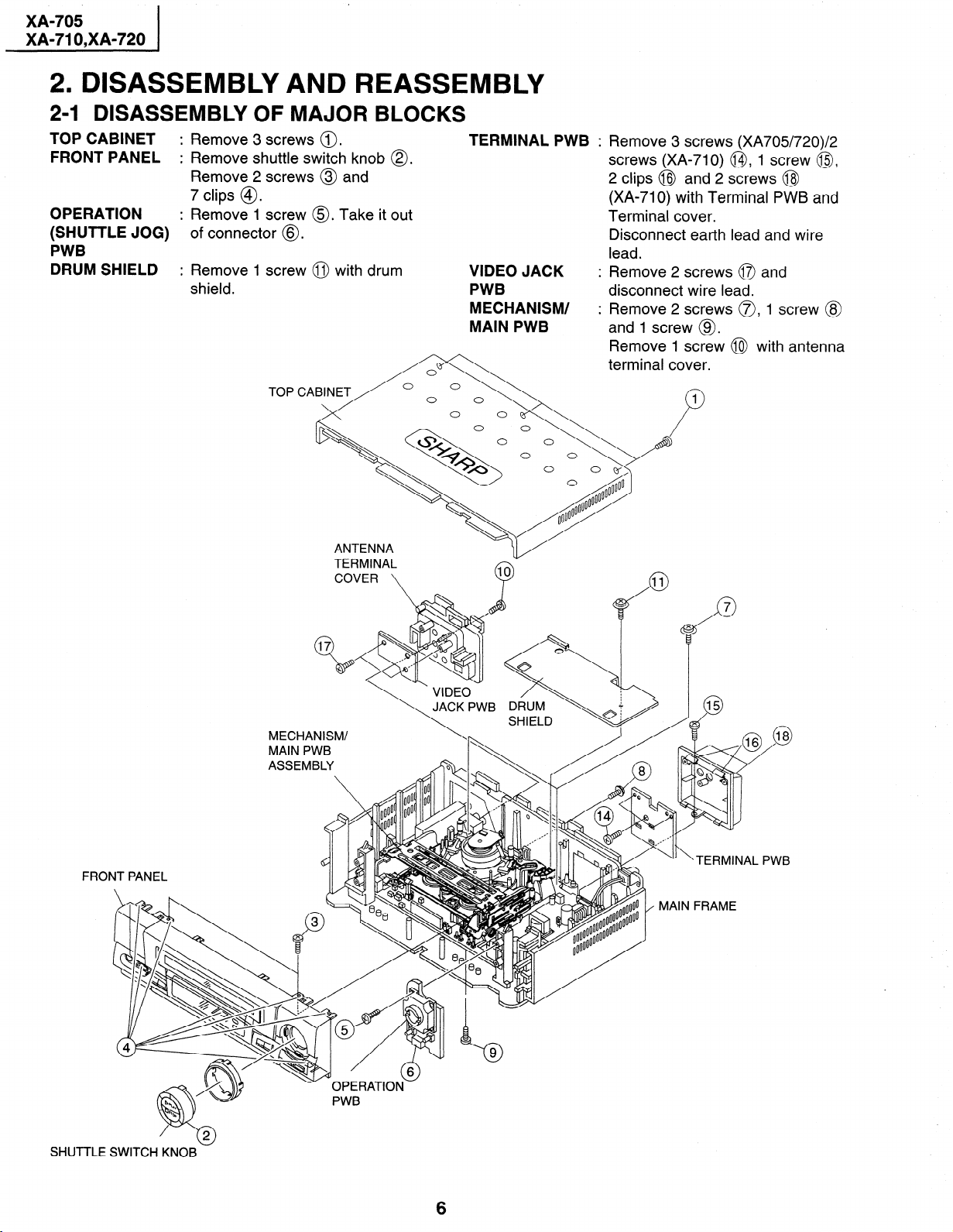
2. DISASSEMBLY AND REASSEMBLY
24 DISASSEMBLY OF MAJOR BLOCKS
TOP CABINET
FRONT PANEL
OPERATION
(SHUTTLE JOG)
PWB
DRUM SHIELD
: Remove 3 screws 0.
: Remove shuttle switch knob 0.
Remove 2 screws @ and
7 clips @.
: Remove 1 screw 0. Take it out
of connector @.
: Remove 1 screw @ with drum
shield.
TERMINAL PWB :
VIDEO JACK
PWB
MECHANISM/
MAIN PWB
Remove 3 screws (XA705/720)/2
screws (XA-710) @I, 1 screw @,
2 clips @J and 2 screws @I
(XA-710) with Terminal PWB and
Terminal cover.
Disconnect earth lead and wire
lead.
Remove 2 screws 0 and
disconnect wire lead.
Remove 2 screws a, 1 screw @
and 1 screw @.
Remove 1 screw @I with antenna
terminal cover.
TOP CABINET
MECHANISM/
:,.
FRO
SHUTTLE
6
Page 7
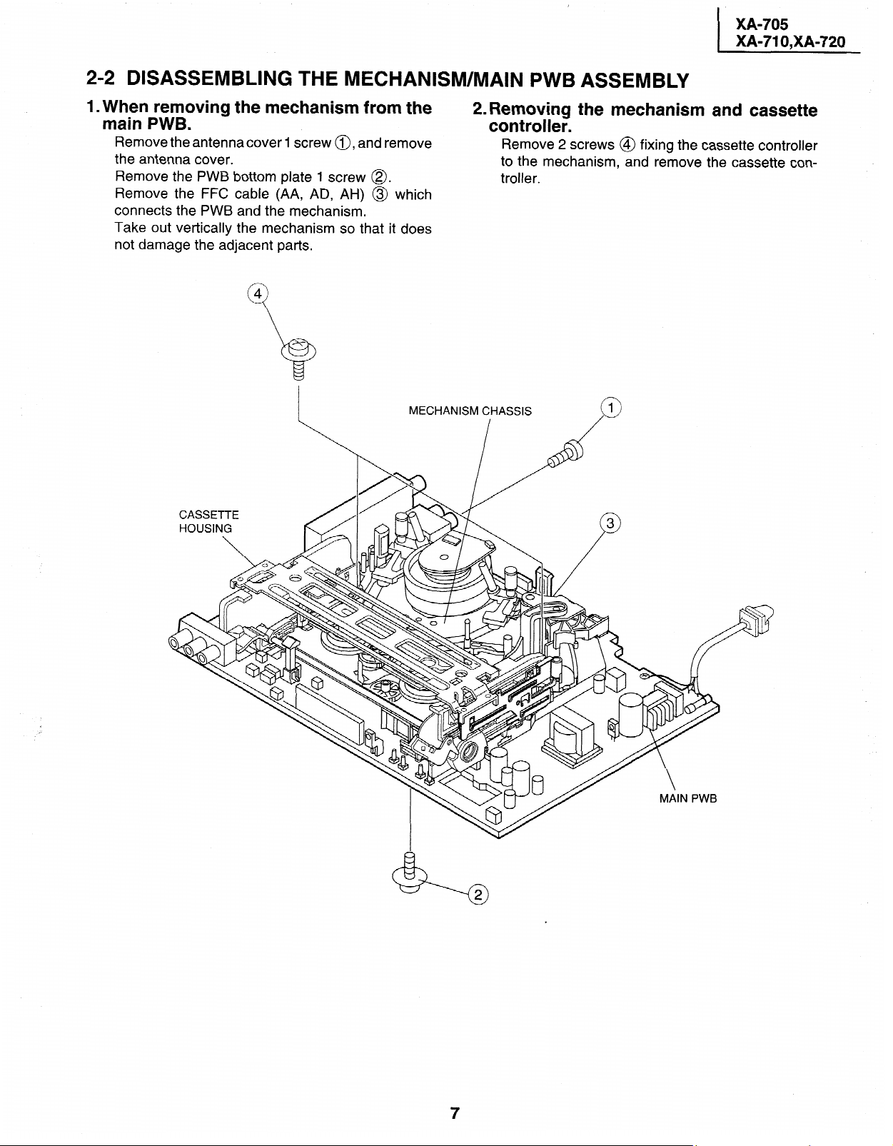
2-2 DISASSEMBLING THE MECHANISM/MAIN PWB ASSEMBLY
1. When removing the mechanism from the main PWB.
Remove the antennacover
the antenna cover.
PWB bottom plate 1 screw @.
Remove
Remove the FFC
connects the PWB and the mechanism.
Take out vertically
not damage the adjacent parts.
the
cable (AA, AD, AH) @ which
the mechanism so
1 screw a, and remove
it does
that
MECHANISM CHASSIS
_I_
2. Removing the mechanism and cassette controller.
Remove 2 screws @
the mechanism, and remove the
to
troller.
fixing the cassette controller
cassette
con-
Page 8
XA-705
XA-71 O,XA-720
I
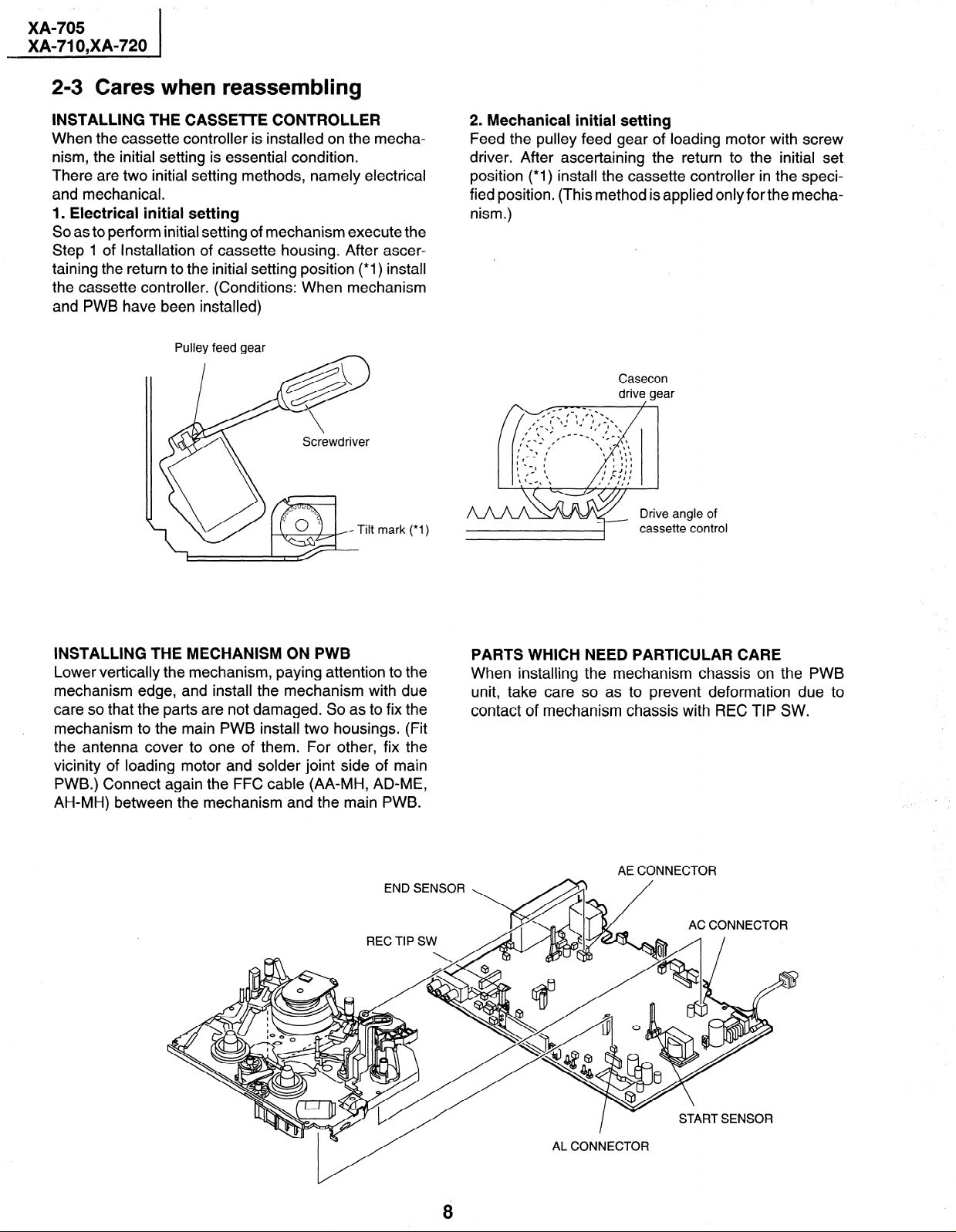
2-3 Cares when reassembling
INSTALLING THE CASSElTE CONTROLLER
When the cassette controller is installed on the mecha-
nism, the initial setting is essential condition.
There are two initial setting methods, namely electrical
and mechanical.
1. Electrical initial setting
So as to perform initial setting of mechanism execute the
Step 1 of Installation of cassette housing. After ascertaining the return to the initial setting position (*I) install
the cassette controller. (Conditions: When mechanism
and PWB have been installed)
Pulley feed gear
mark (*I)
2. Mechanical initial setting
Feed the pulley feed gear of loading motor with screw
driver. After ascertaining the return to the initial set
position (*I) install the cassette controller in the speci-
fied position. (This method is applied only for the mecha-
nism.)
/
Casecon
drive gear
angle of
casse
tte control
INSTALLING THE MECHANISM ON PWB
Lower vertically the mechanism, paying attention to the
mechanism edge, and install the mechanism with due
care so that the parts are not damaged. So as to fix the
mechanism to the main PWB install two housings. (Fit
the antenna cover to one of them. For other, fix the
vicinity of loading motor and solder joint side of main
PWB.) Connect again the FFC cable (AA-MH, AD-ME,
AH-MH) between the mechanism and the main PWB.
END SENSOR
REC TIP SW
PARTS WHICH NEED PARTICULAR CARE
When installing the mechanism chassis on the PWB
unit, take care so as to prevent deformation due to
contact of mechanism chassis with REC TIP SW.
AE CONNECTOR
AC CONNECTOR
8
Page 9
XA-705
XA-71 O,XA-720
I
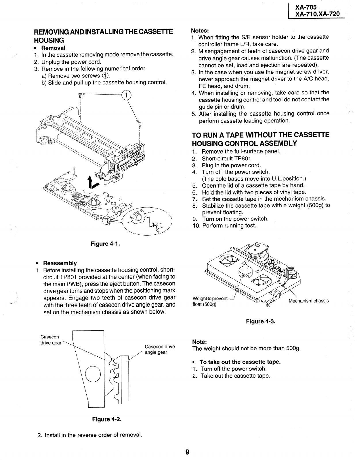
REMOVING AND INSTALLING THE CASSETTE
HOUSING
l Removal
1. In the cassette removing mode remove the cassette.
2. Unplug the power cord.
3. Remove in the following numerical order.
a) Remove two screws 0.
b) Slide and pull up the cassette housing control.
Notes:
1.
When fitting the S/E sensor holder to the cassette
controller frame L/R, take care.
2.
Misengagement of teeth of casecon drive gear and
drive angle gear causes malfunction. (The cassette
cannot be set, load and ejection are repeated).
.
In the case when you use the magnet screw driver,
3
never approach the magnet driver to the A/C head,
FE head, and drum.
4.
When installing or removing, take care so that the
cassette housing control and tool do not contact the
guide pin or drum.
.
After installing the cassette housing control once
5
perform cassette loading operation.
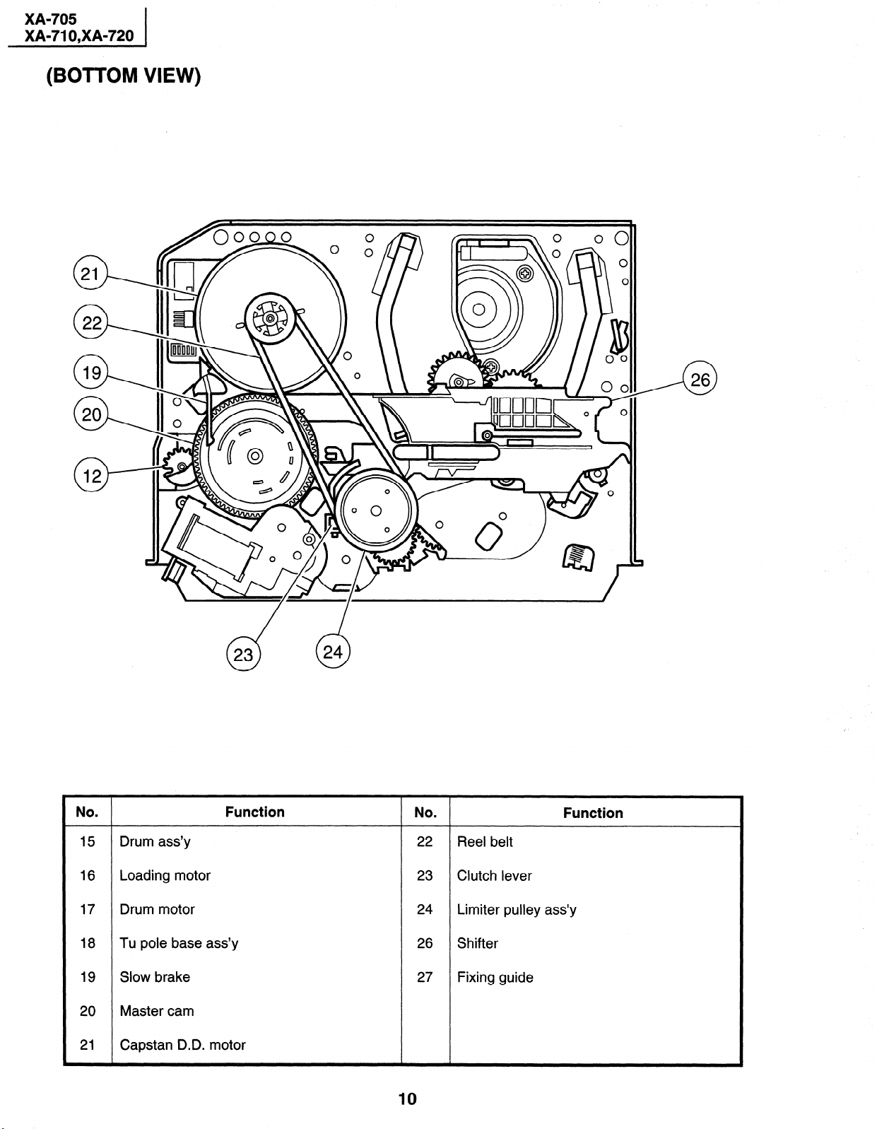
TO RUN A TAPE WITHOUT THE CASSETTE
HOUSING CONTROL ASSEMBLY
1 .
Remove the full-surface panel.
2 .
Short-circuit TP801.
Plug in the power cord.
3
4:
Turn off the power switch.
(The pole bases move into U.L.position.)
5 .
Open the lid of a cassette tape by hand.
Hold the lid with two pieces of vinyl tape.
6
7:
Set the cassette tape in the mechanism chassis.
.
Stabilize the cassette tape with a weight (500g) to
8
prevent floating.
9 . Turn on the power switch.
Perform running test.
10
Figure 4-I.
0 Reassembly
1. Before installing the cassette housing control, shortcircuit TP801 provided at the center (when facing to
the main PWB), press the eject button. The casecon
drive gear turns and stops when the positioning mark
. .
appears. Engage two teeth of casecon drive gear
with the three teeth of casecon drive angle gear, and
set on the mechanism chassis as shown below.
Casecon
Casecon drive
angle gear
-7
/
Weight to prevent
Figure 4-3.
Note:
The weight should not be more than 500g.
0 To take out the cassette tape.
1. Turn off the power switch.
2. Take out the cassette tape.
Mechanism chassis
Figure 4-2.
2. Install in the reverse order of removal.
Page 10
XA-705
XA-71 O,XA-720
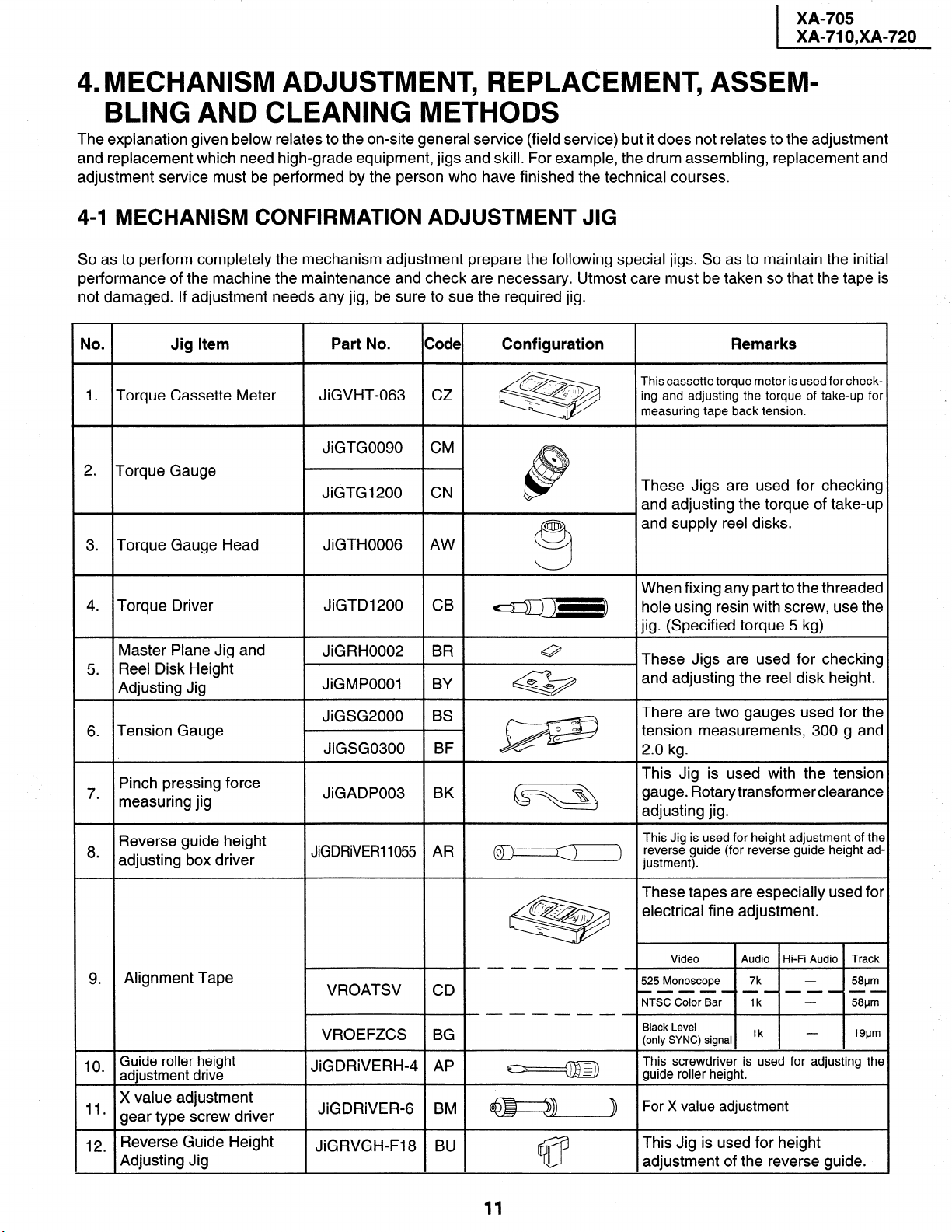
(BOTTOM VIEW)
. Function
No
NO
. Function
15 Drum ass’y 22 Reel belt
16 Loading motor 23 Clutch lever
17 Drum motor 24 Limiter pulley ass’y
18 Tu pole base ass’y 26 Shifter
19 Slow brake 27 Fixing guide
20 Master cam
21 Capstan D.D. motor
10
Page 11
XA-705
XA-71 O,XA-720
MECHANISM ADJUSTMENT, REPLACEMENT, ASSEM-
4.
BLING AND CLEANING METHODS
The explanation given below relates to the on-site general service (field service) but it does not relates to the adjustment
and replacement which need high-grade equipment, jigs and skill. For example, the drum assembling, replacement and
adjustment service must be performed by the person who have finished the technical courses.
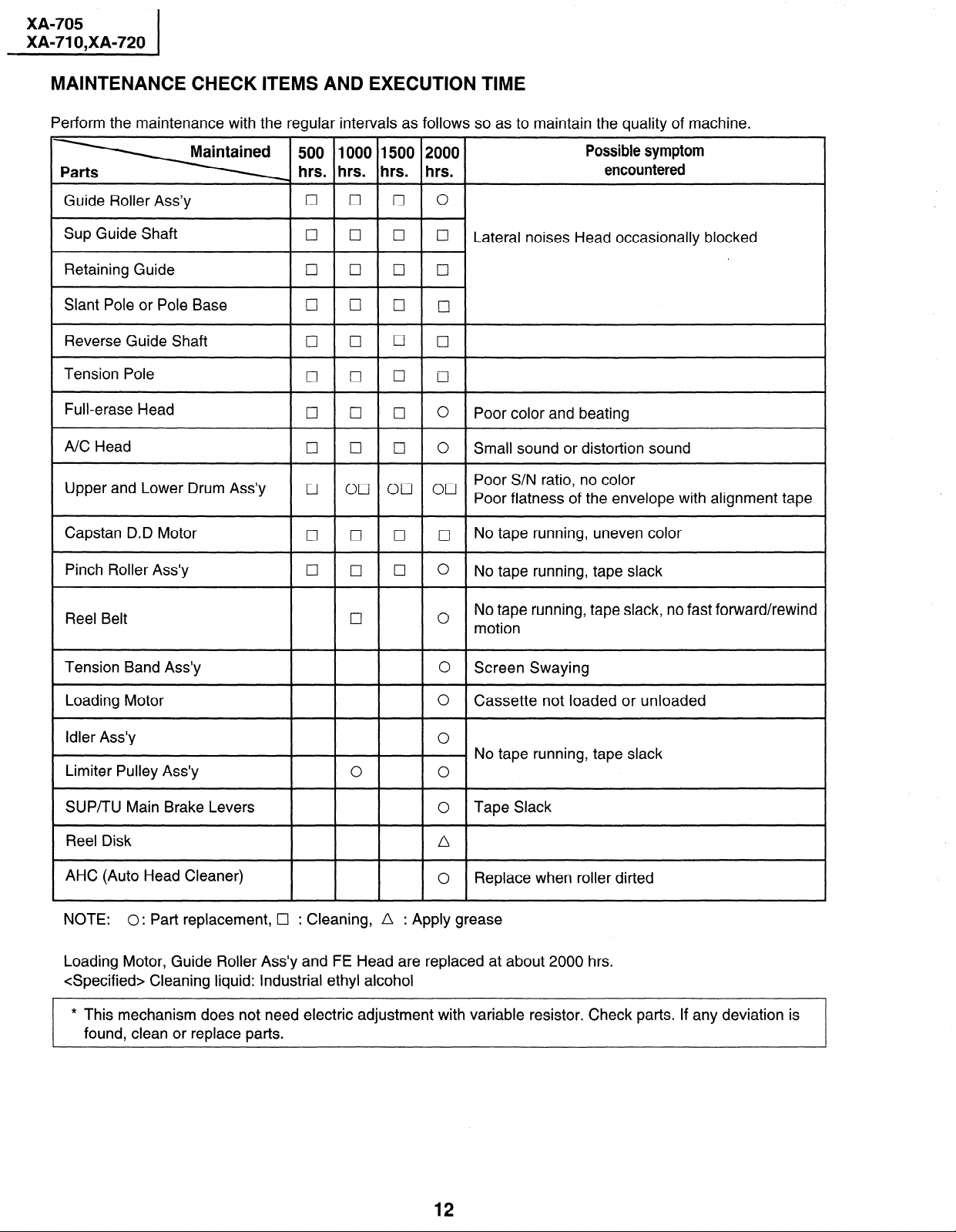
4-l MECHANISM CONFIRMATION ADJUSTMENT JIG
So as to perform completely the mechanism adjustment prepare the following special jigs. So as to maintain the initial
performance of the machine the maintenance and check are necessary. Utmost care must be taken so that the tape is
not damaged. If adjustment needs any jig, be sure to sue the required jig.
.
No
1.
Torque Cassette Meter
Jig Item
Part No.
JiGVHT-063 CZ
Code Configuration
&!5$2@
Remarks
This cassette torque meter is used for checking and adjusting the torque of take-up for
measuring tape back tension.
These Jigs are used for checking
and adjusting the torque of take-up
and supply reel disks.
and adjusting the reel disk height.
transformer clearance
10 Guide roller height
’ adjustment drive
X value adjustment
“*
gear type screw driver
12
Reverse Guide Height
.
Adjusting Jig
JiGDRiVERH-4 AP
JiGDRiVER- BM @------$$
JiGRVGH-F18 BU
11
This screwdriver is used for adjusting the
guide roller height.
For X value adjustment
This Jig is used for height
adjustment of the reverse guide.
Page 12
XA-705
XA-71 O,XA-720
MAINTENANCE CHECK ITEMS AND EXECUTION TIME
Perform the maintenance with the regular intervals as follows so as to maintain the quality of machine.
500 1000 1500 2000
hrs. hrs. hrs. hrs.
Guide Roller Ass’y
Sup Guide Shaft
Retaining Guide cl
cl 0 q
cl
cl
q
q
Cl cl
Slant Pole or Pole Base cl (7 q
Reverse Guide Shaft
Tension Pole
Full-erase Head
A/C Head
Upper and Lower Drum Ass’y
Capstan D.D Motor
Pinch Roller Ass’y 0
cl
q
q
I7 0 q
0
ocl on 00
II 0 0 q
q
0
cl
cl
0
0
0
0
Possible symptom
encountered
0
0
Lateral noises Head occasionally blocked
q
cl
CII
0
Poor color and beating
0
Small sound or distortion sound
Poor S/N ratio, no color
Poor flatness of the envelope with alignment tape
No tape running, uneven color
0
No tape running, tape slack
No tape running, tape slack, no fast forward/rewind
Reel Belt
Tension Band Ass’y
Loading Motor
Idler Ass’y
cl
0
motion
0 Screen Swaying
0
Cassette not loaded or unloaded
0
No tape running, tape slack
Limiter Pulley Ass’y 0
SUP/TU Main Brake Levers 0
0
Tape Slack
Reel Disk /\
AHC (Auto Head Cleaner)
l
NOTE:
0: Part replacement, Cl : Cleaning, n : Apply grease
Replace when roller dirted
0
Loading Motor, Guide Roller Ass’y and FE Head are replaced at about 2000 hrs.
<Specified> Cleaning liquid: Industrial ethyl alcohol
* This mechanism does not need electric adjustment with variable resistor. Check parts. If any deviation is
found, clean or replace parts.
12
Page 13
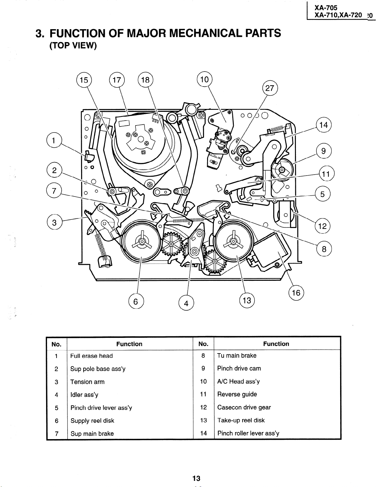
3. FUNCTION OF MAJOR MECHANICAL PARTS
(TOP VIEW)
n 37
XA-705
XA-71 O,XA-720 !O
No
6
0
.
Full erase head
Sup pole base ass’y
Tension arm
Idler ass’y
Pinch drive lever ass’y
Supply reel disk
Sup main brake 14
Function No .
n
4
13
8
Tu main brake
9
Pinch drive cam
10
NC Head ass’y
11
Reverse guide
12
Casecon drive gear
13
Take-up reel disk
Pinch roller lever ass’y
Function
Page 14
XA-705
r XA-71 O,XA-720
r
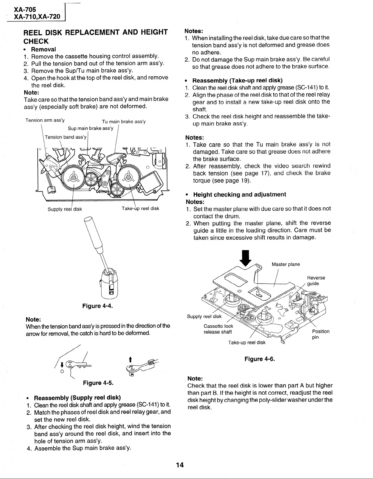
REEL DISK REPLACEMENT AND HEIGHT
CHECK
0
Removal
Remove the cassette housing control assembly.
1.
.
Pull the tension band out of the tension arm ass’y.
2
Remove the Sup/Tu main brake ass’y.
3
4:
Open the hook at the top of the reel disk, and remove
the reel disk.
Note:
Take care so that the tension band ass’y and main brake
ass’y (especially soft brake) are not deformed.
Tension arm ass’y
Sup main brake ass’y
Tension band ass’y
Supply reel’ disk
Tu main brake ass’y
I
Take-hp reel disk
Notes:
1 .
When installing the reel disk, take due care so that the
tension band ass’y is not deformed and grease does
no adhere.
2.
Do not damage the Sup main brake ass’y. Be careful
so that grease does not adhere to the brake surface.
0
Reassembly (Take-up reel disk)
1.
Clean the reel disk shaft and apply grease (SC-141) to it.
. d
2
Align the phase of the reel disk to that of the reel relay
gear and to install a new take-up reel disk onto the
shaft.
3
Check the reel disk height and reassemble the takeup main brake ass’y.
Notes:
I. Take care so that the Tu main brake ass’y is not
damaged. Take care so that grease does not adhere
the brake surface.
2. After reassembly, check the video search rewind
back tension (see page 17) and check the brake
torque (see page 19).
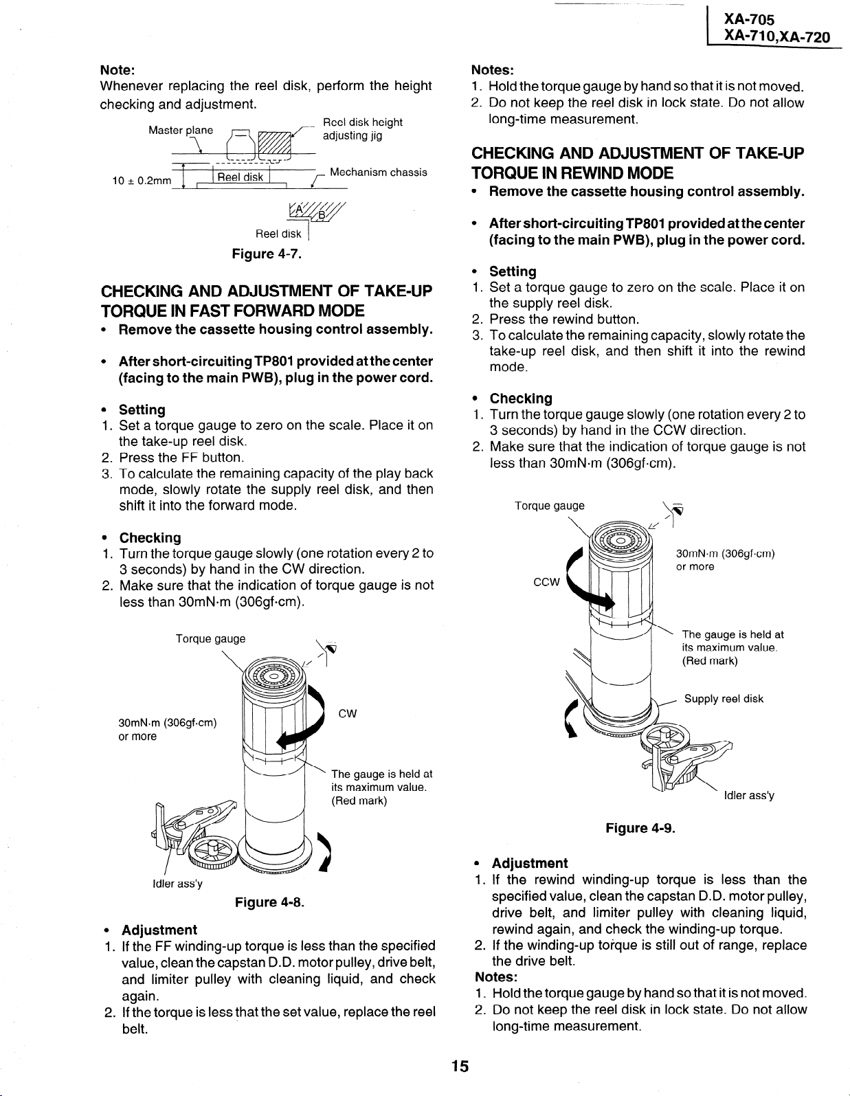
l Height checking and adjustment
Notes:
1.
Set the master plane with due care so that it does not
contact the drum.
2 .
When putting the master plane, shift the reverse
guide a little in the loading direction. Care must be
taken since excessive shift results in damage.
Figure 4-4.
Note:
When the tension band a&y is pressed in the direction of the
arrow for removal, the catch is hard to be deformed.
Figure 4-5.
0
Reassembly (Supply reel disk)
Clean the reel disk shaft and apply grease (SC-141) to it.
1 .
Match the phases of reel disk and reel relay gear, and
2 .
set the new reel disk.
After checking the reel disk height, wind the tension
3 .
band ass’y around the reel disk, and insert into the
hole of tension arm ass’y.
Assemble the Sup main brake ass’y.
4 .
Myter plane
SUPPl
Take-up reel disk
Figure 4-6.
Note:
Check that the reel disk is lower than part A but higher
than part B. If the height is not correct, readjust the reel
disk height by changing the poly-slider washer under the
reel disk.
14
Page 15
Note:
Whenever replacing the reel disk, perform the height
checking and adjustment.
Reel disk height
adjusting jig
t
10+0.2mm + ,
Reel disk
I f
Mechanism chassis
fjqgy
Reel disk
1
Figure 4-7.
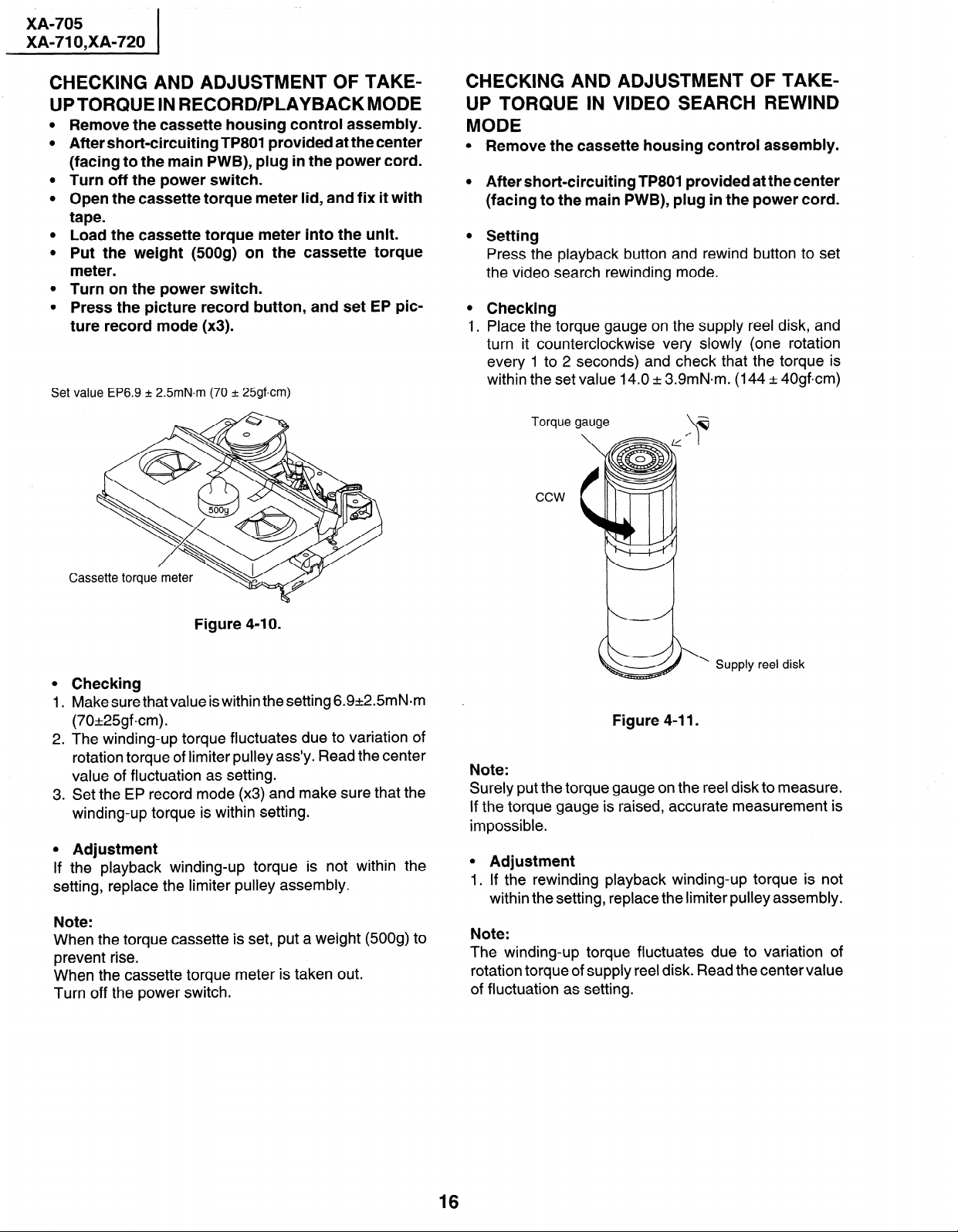
CHECKING AND ADJUSTMENT OF TAKE-UP TORQUE IN FAST FORWARD MODE
0
Remove the cassette housing control assembly.
0
After short-circuiting TP801 provided at the center
(facing to the main PWB), plug in the power cord.
0
Setting
Set a torque gauge to zero on the scale. Place it on
1.
the take-up reel disk.
2.
Press the FF button.
.
To calculate the remaining capacity of the play back
3
mode, slowly rotate the supply reel disk, and then
shift it into the forward mode.
0
Checking
1.
Turn the torque gauge slowly (one rotation every 2 to
3 seconds) by hand in the CW direction.
.
Make sure that the indication of torque gauge is not
2
less than 30mN.m (306gfcm).
Notes:
1. Hold the torque gauge by hand so that it is not moved.
2. Do not keep the reel disk in lock state. Do not allow
long-time measurement.
CHECKING AND ADJUSTMENT OF TAKE-UP
TORQUE IN REWIND MODE
0
Remove the cassette housing control assembly.
0
After short-circuiting TP801 provided at the center
(facing to the main PWB), plug in the power cord.
0
Setting
1.
Set a torque gauge to zero on the scale. Place it on
the supply reel disk.
2.
Press the rewind button.
.
To calculate the remaining capacity, slowly rotate the
3
take-up reel disk, and then shift it into the rewind
mode.
0
Checking
1.
Turn the torque gauge slowly (one rotation every 2 to
3 seconds) by hand in the CCW direction.
2.
Make sure that the indication of torque gauge is not
less than 30mN*m (306gfcm).
Torque gauge
\
30mN.m (306gf-cm)
or more
Torque gauge
30mN-m (306gf.cm)
or more
Idler ass’y
\
cw
The gauge is held at
its maximum value.
(Red mark)
Figure 4-8.
0
Adjustment
I
. . If the FF winding-up torque is less than the specified
value, clean the capstan D.D. motor pulley, drive belt,
and limiter pulley with cleaning liquid, and check
again.
2. If the torque is less that the set value, replace the reel
belt.
-_ The gauge is held at
its maximum value.
(Red mark)
disk
r ass’y
Figure 4-9.
0
Adjustment
1
I . If the rewind winding-up torque is less than the
specified value, clean the capstan D.D. motor pulley,
drive belt, and limiter pulley with cleaning liquid,
rewind again, and check the winding-up torque.
2. If the winding-up torque is still out of range, replace
the drive belt.
Notes:
1. Hold the torque gauge by hand so that it is not moved.
2. Do not keep the reel disk in lock state. Do not allow
long-time measurement.
15
Page 16
XA-705
XA-71 O,XA-720
CHECKING AND ADJUSTMENT OF TAKEUPTORQUE IN RECORD/PLAYBACKMODE
Remove the cassette housing control assembly.
After short-circuiting TP801 provided at the center
(facing to the main PWB), plug in the power cord.
Turn off the power switch.
Open the cassette torque meter lid, and fix it with
tape.
Load the cassette torque meter into the unit.
Put the weight (500g) on the cassette torque
meter.
Turn on the power switch.
Press the picture record button, and set EP pic-
ture record mode (x3).
Set value EP6.9 + 2.5mN.m (70 + 25gf-cm)
CHECKING AND ADJUSTMENT OF TAKEUP TORQUE IN VIDEO SEARCH REWIND
MODE
l -Remove the cassette housing control assembly.
l After short-circuiting TP801 provided at the center
(facing to the main PWB), plug in the power cord.
l Setting
Press the playback button and rewind bu
the video search rewinding mode.
l Checking
1. Place the torque gauge on the supply ree
turn it counterclockwise very slowly (one rotation
every 1 to 2 seconds) and check that the torque is
within the set value 14.0 k 3.9mN.m. (144 k 40gfcm)
Torque gauge
*
\
ton to set
disk, and
ccw
Figure 4-l 0.
0
Checking
1 .
Make sure that value is within the setting 6.9+2.5mN.m
(70*25gfcm).
2 .
The winding-up torque fluctuates due to variation of
rotation torque of limiter pulley ass’y. Read the center
value of fluctuation as setting.
.
Set the EP record mode (x3) and make sure that the
3
winding-up torque is within setting.
0
Adjustment
If
the playback winding-up torque is not within the
setting, replace the limiter pulley assembly.
Note:
When the torque cassette is set, put a weight (500g) to
prevent rise.
When the cassette torque meter is taken out.
Turn off the power switch.
\
Supply reel disk
Figure 4-11.
Note:
Surely put the torque gauge on the reel disk to measure.
If the torque gauge is raised, accurate measurement is
impossible.
l Adjustment
1. If the rewinding playback winding-up torque is not
within the setting, replace the limiter pulley assembly.
Note:
The winding-up torque fluctuates due to variation of
rotation torque of supply reel disk. Read the center value
of fluctuation as setting.
16
Page 17
CHECKING THE VIDEO SEARCH REWIND
I
BACK TENSION
Remove the cassette housing control assembly.
XA-705
XA-71 O,XA-720
After short-circuiting TP801 provided at the center
(facing to the main PWB), plug in the power cord.
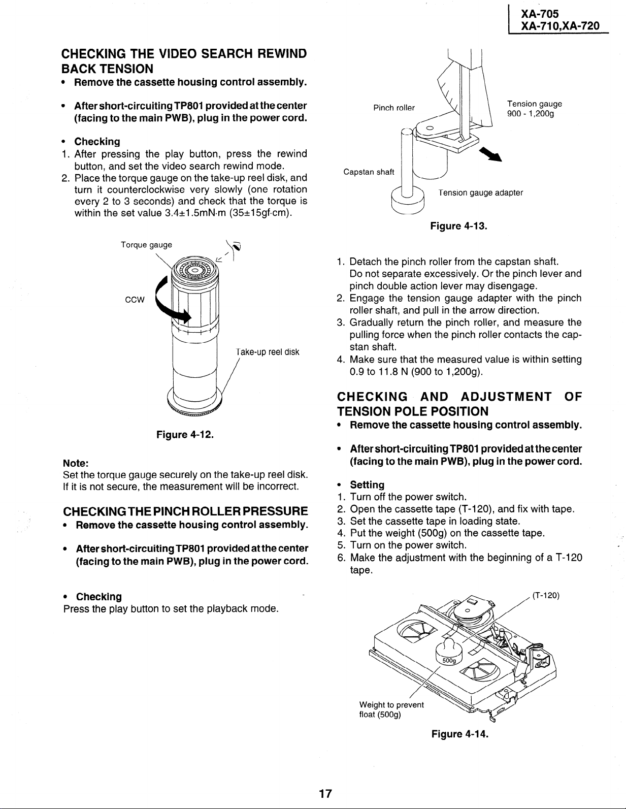
Checking
After pressing the play button, press the rewind
button, and set the video search rewind mode.
Place the torque gauge on the take-up reel disk, and
turn it counterclockwise very slowly (one rotation
every 2 to 3 seconds) and check that the torque is
within the set value 3.4+1.5mN.m (35+15gfcm).
Torque gauge
ccw
Take-up reel disk
/
Figure 4-l 2.
Note:
Set the torque gauge securely on the take-up reel disk.
If it is not secure, the measurement will be incorrect.
CHECKINGTHE PINCH ROLLER PRESSURE
l Remove the cassette housing control assembly.
l After short-circuiting TP801 provided at the center
(facing to the main PWB), plug in the power cord.
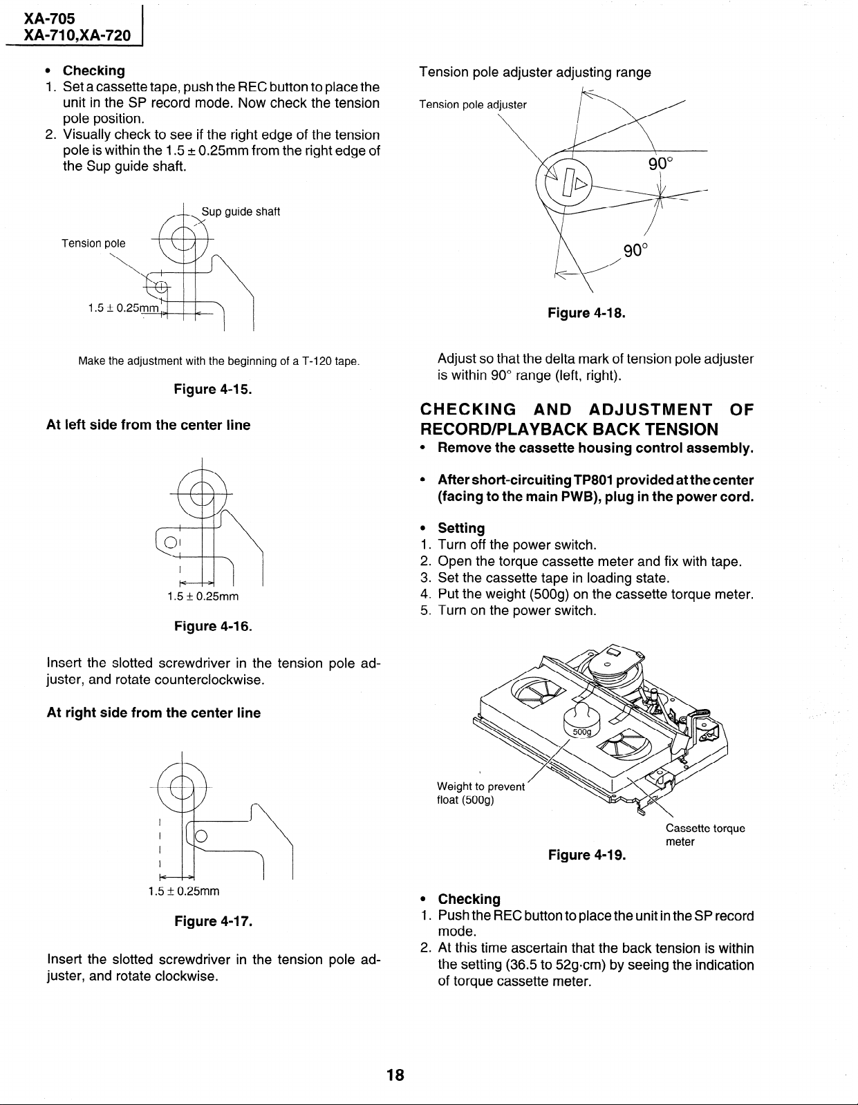
Tension gauge
900 - 1,200g
Capstan shaft
Y
1.
Detach the pinch roller from the capstan shaft.
Do not separate excessively. Or the pinch lever and
pinch double action lever may disengage.
.
2
Engage the tension gauge adapter with the pinch
roller shaft, and pull in the arrow direction.
.
Gradually return the pinch roller, and measure the
3
pulling force when the pinch roller contacts the capstan shaft.
4.
Make sure that the measured value is within setting
0.9 to 11.8 N (900 to 1,200g).
Tension gauge adapter
Figure 4-13.
CHECKING AND ADJUSTMENT OF
TENSION POLE POSITION
l Remove the cassette housing control assembly.
l After short-circuiting TP801 provided at the center
(facing to the main PWB), plug in the power cord.
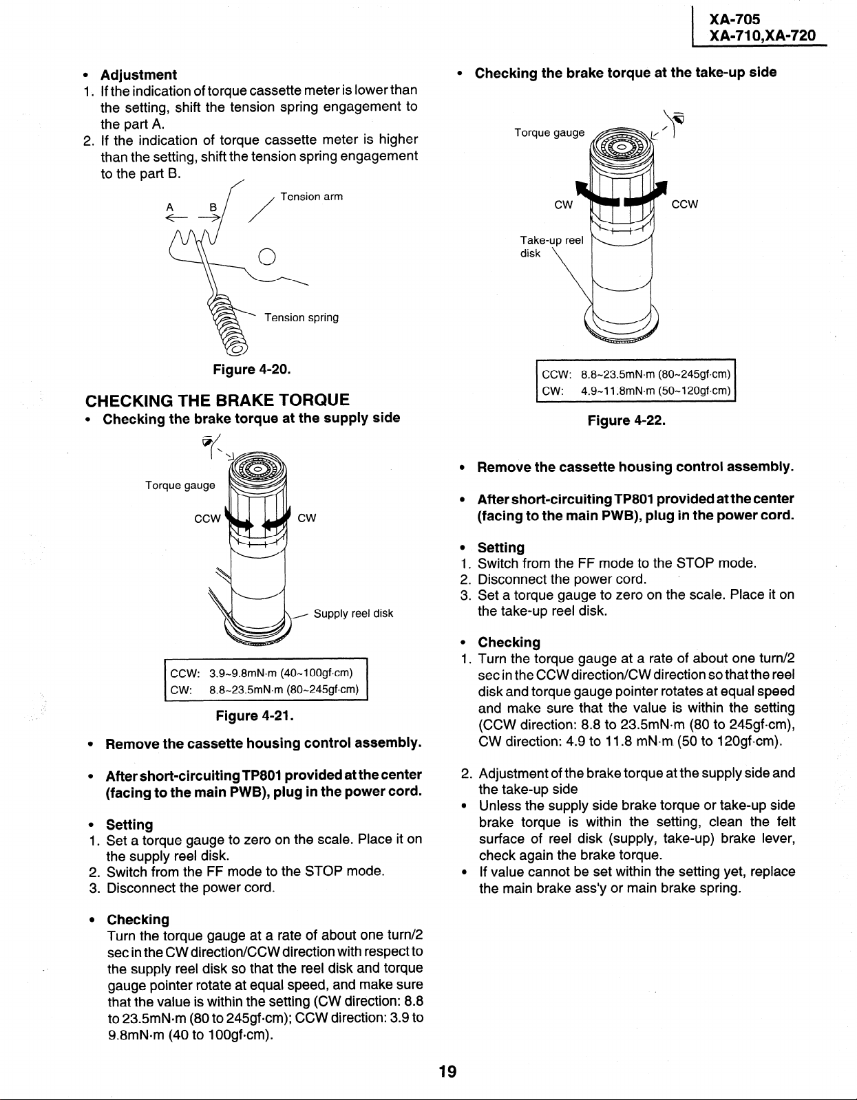
l Setting
1. Turn off the power switch.
2. Open the cassette tape (T-120), and fix with tape.
3. Set the cassette tape in loading state.
4. Put the weight (500s) on the cassette tape.
5. Turn on the power switch.
6. Make the adjustment with the beginning of a T-120
tape.
0 Checking
Press the play button to set the playback mode.
Weight to prevent
float (500s)
Figure 4-l 4.
17
Page 18
XA-705
XA-71 O,XA-720
0
Checking
1.
Set a cassette
unit in the SP
tape, push the REC button to place the
record mode. Now check the tension
pole position.
2.
Visually check to see if the right edge of the tension
pole is within the 1.5 + 0.25mm from the right edge of
the Sup guide shaft.
Sup guide shaft
A-h
Make the adjustment with the beginning of a T-120 tape.
Figure 4-15.
At left side from the center line
Tension pole adjuster adjusting range
Tension pole
Figure 4-18.
Adjust so that the delta mark of tension pole adjuster
is within 90” range (left, right).
CHECKING AND ADJUSTMENT OF RECORD/PLAYBACK BACK TENSION
0
Remove the cassette housing control assembly.
1.5 * 0.25mm
Figure 4-l 6.
Insert the slotted screwdriver in the tension pole ad-
juster, and rotate counterclockwise.
At right side from the center line
0
After short-circuiting TP801 provided at the center
(facing to the main PWB), plug in the power cord.
0
Setting
1
Turn off the power switch.
2:
Open the torque cassette meter and fix with tape.
3
Set the cassette tape in loading state.
4:
Put the weight (500g) on the cassette torque meter.
.
5
Turn on the power switch.
Weight to prevent
float (500g)
Cassette torque
meter
Figure 4-19.
1.5 k 0.25mm
Figure 4-l 7.
Insert the slotted screwdriver in the tension pole ad-
juster, and rotate clockwise.
18
0
Checking
1.
Push the REC button to place the unit in the SP record
mode.
.
2
At this time ascertain that the back tension is within
the setting (36.5 to 52gcm) by seeing the indication
of torque cassette meter.
Page 19
l Adjustment
1. If the indication of torque cassette meter is lower than
the setting, shift the tension spring engagement to
the part A.
2. If the indication of torque cassette meter is higher
than the setting, shift the tension spring engagement
to the part 9.
A B
+---+
f
Tension arm
/
Tension spring
XA-705
XA-71 O,XA-720
I
0
Checking the brake torque at the take-up side
Torque
Take-1
up reel K ‘//
disk
Figure 4-20.
CHECKING THE BRAKE TORQUE
0
Checking the brake torque at the supply side
@/
\
I
Torque gauge
Supply reel disk
3.9-9.8mN.m (40-I OOgfxm)
8.8-23.5mN.m (80-245gf.cm)
Figure 4-21.
Remove the cassette housing control assembly.
CCW: 8.8-23.5mN.m (80-245gf.cm)
cw: 4.9-11.8mN.m (50-I 20gf.cm)
Figure 4-22.
0
Remove the cassette housing control assembly.
0
After short-circuiting TP801 provided at the center
(facing to the main PWB), plug in the power cord.
0
Setting
1.
Switch from the FF mode to the STOP mode.
2 .
Disconnect the power cord. .
3 .
Set a torque gauge to zero on the scale. Place it on
the take-up reel disk.
0
Checking
1.
Turn the torque gauge at a rate of about one turn/2
set in the CCW direction/CW direction so that the reel
disk and torque gauge pointer rotates at equal speed
and make sure that the value is within the setting
(CCW direction: 8.8 to 23.5mN.m (80 to 245gfcm),
CW direction: 4.9 to 11.8 mN-m (50 to 120gfcm).
0
After short-circuiting TPSOI provided at the center
(facing to the main PWB), plug in the power cord.
0
Setting
Set a torque gauge to zero on the scale. Place it on
1 .
the supply reel disk.
Switch from the FF mode to the STOP mode.
2 .
Disconnect the power cord.
3 .
0
Checking
Turn the torque gauge at a rate of about one turn/2
set in the CW direction/CCW direction with respect to
the supply reel disk so that the reel disk and torque
gauge pointer rotate at equal speed, and make sure
that the value is within the setting (CW direction: 8.8
to 23.5mN.m (80 to 245gfcm); CCW direction: 3.9 to
9.8mN*m (40 to 1OOgfcm).
2
Adjustment of the brake torque at the supply side and
.
the take-up side
0
Unless the supply side brake torque or take-up side
brake torque is within the setting, clean the felt
surface of reel disk (supply, take-up) brake lever,
check again the brake torque.
0
If value cannot be set within the setting yet, replace
the main brake ass’y or main brake spring.
19
Page 20
XA-705
XA-71 O,XA-720
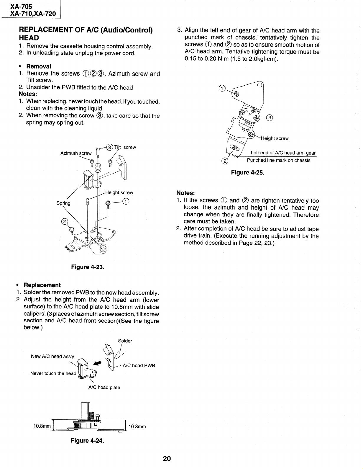
REPLACEMENT OF A/C (Audio/Control) HEAD
1. Remove the cassette housing control assembly.
2. In unloading state unplug the power cord.
l Removal
1. Remove the screws @@@, Azimuth screw and
Tilt screw.
2. Unsolder the PWB fitted to the A/C head
Notes:
When replacing, never touch the head. If you touched,
1.
clean with the cleaning liquid.
2. When removing the screw 0, take care so that the
spring may spring out.
3. Align the left end of gear of A/C head arm with the
punched mark of chassis, tentatively tighten the
screws @ and @ so as to ensure smooth motion of
A/C head arm. Tentative tightening torque must be
0.15 to 0.20 N*m (1.5 to 2.0kgfcm).
Figure 4-25.
Notes:
1 .
If the screws @ and @
loose, the azimuth and
change when they are finally tightened. Therefore
care must be taken.
2.
After completion of A/C head be sure to adjust tape
drive train. (Execute the running adjustment by the
method described in Page 22, 23.)
are tighten tentatively too
height of A/C head may
Figure 4-23.
0
Replacement
1
Solder the removed PWB to the new head assembly.
2. Adjust the height from the A/C head arm (lower
surface) to the A/C head plate to 10.8mm with slide
calipers. (3 places of azimuth screw section, tilt screw
section and A/C head front section)(See the figure
below.)
Solder
head PWB
Never touch the head
A/C head plate
10.8mm
10.8mm
Figure 4-24.
20
Page 21
XA-705
I
i XA-71 O,XA-720
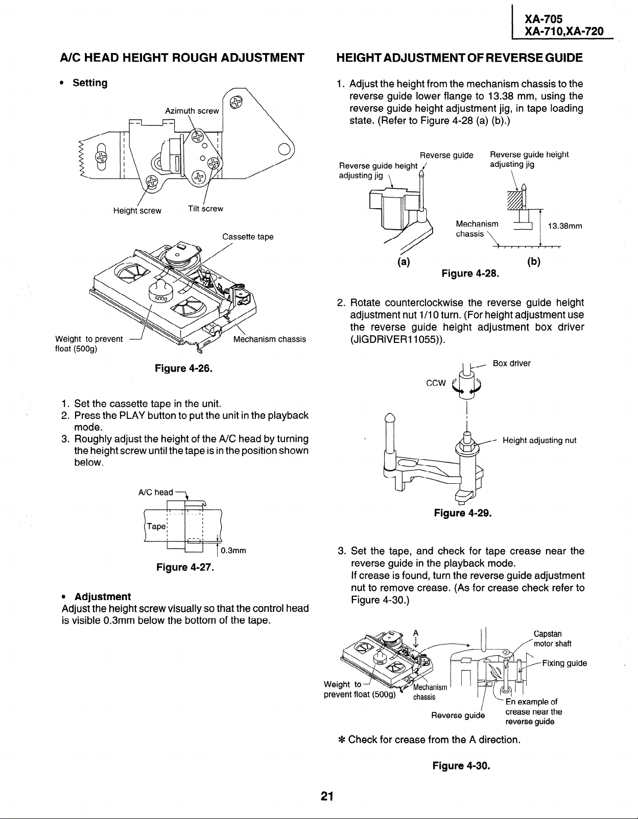
A/C HEAD HEIGHT ROUGH ADJUSTMENT
l Setting
f@ \
Cassette tape
Mechanism chassis
Weight to prevent
float (500g)
/
Height screw
Azimuth screw
Tilt &rew
Figure 4-26.
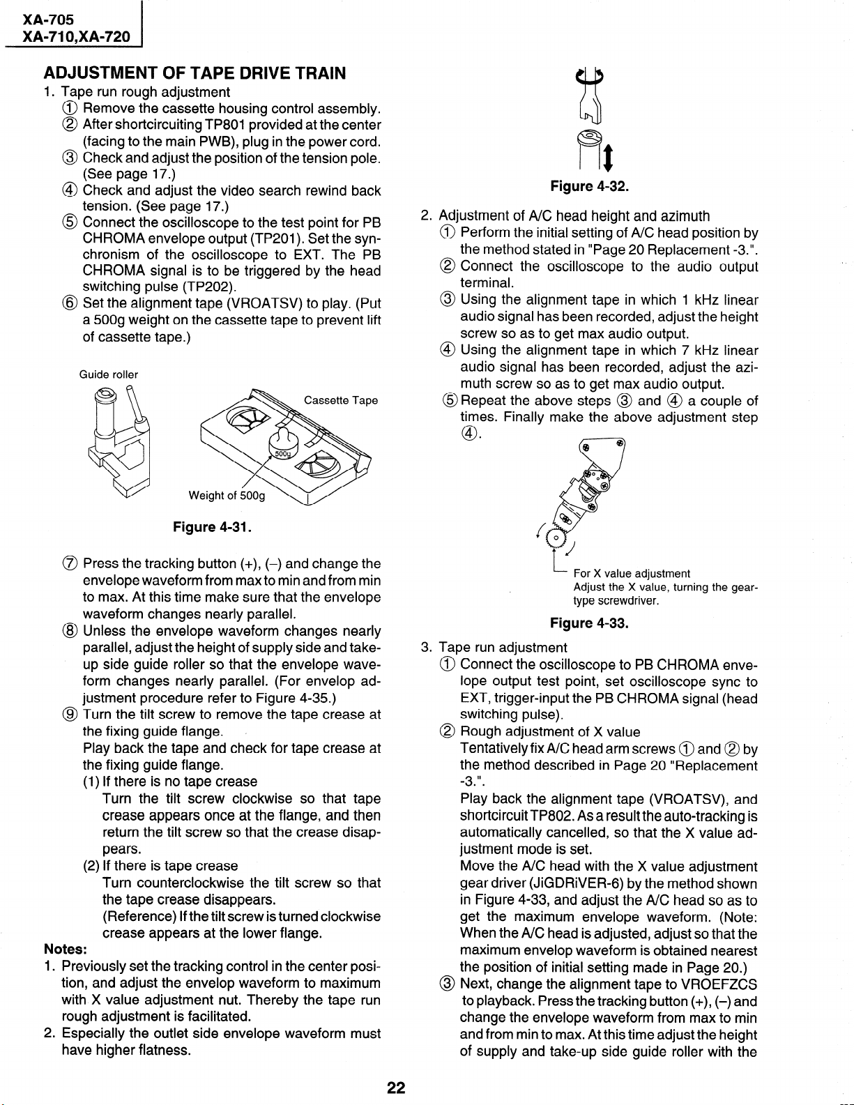
HEIGHTADJUSTMENTOFREVERSEGUIDE
1 Adjust the height from the mechanism chassis to the
reverse guide lower flange to 13.38 mm, using the
reverse guide height adjustment jig, in tape loading
state. (Refer to Figure 4-28 (a) (b).)
Reverse guide height
adjusting jig
\
Reverse guide height J
adjusting jig
Reverse guide
I?
I
Mechanism
chassis
,$
Figure 4-28.
Rotate counterclockwise the reverse guide height
adjustment nut l/l 0 turn. (For height adjustment use
the reverse guide height adjustment box driver
(JiGDRiVER 1055)).
Box driver
ccw
13.38mm
1. Set the cassette tape in the unit.
2. Press the PLAY button to put the unit in the playback
mode.
3. Roughly adjust the height of the A/C head by turning
the height screw until the tape is in the position shown
below.
A/C head 3
.
Figure 4-27.
0 Adjustment
Adjust the height screw visually so that the control head
is visible 0.3mm below the bottom of the tape.
Height adjusting nut
Figure 4-29.
u. Set the tape, and check for tape crease near the
reverse guide in the playback mode.
If crease is found, turn the reverse guide adjustment
nut to remove crease. (As for crease check refer to
Figure 4-30.)
Capstan
/‘motor shaft
Jide
Reverse guid;
L- En example of
I
crease near the
reverse guide
Fixing gi
* Check for crease
21
from the A direction.
Figure 4-30.
Page 22
XA-705
XA-71 O,XA-720
ADJUSTMENT
1. Tape run rough
Remove the
OF TAPE DRIVE TRAIN
adjustment
cassette housing control assembly.
After shortcircuiting TP801 provided at the center
(facing to the main PWB), plug in the power cord.
Check and adjust the position of the tension pole.
(See page 17.)
Check and adjust the video search rewind back
tension. (See page 17.)
Connect the oscilloscope to the test point for PB
CHROMA envelope output (TP201). Set the synchronism of the oscilloscope to EXT. The PB
CHROMA signal is to be triggered by the head
switching pulse (TP202).
Set the alignment tape (VROATSV) to play. (Put
a 500g weight on the cassette tape to prevent lift
of cassette tape.)
Guide roller
Figure 4-32.
2. Adjustment of A/C head height and azimuth
@ Perform the initial setting of A/C head position by
the method stated in “Page 20 Replacement -3.“.
@ Connect the oscilloscope to the audio output
terminal.
@ Using the alignment tape in which 1 kHz linear
audio signal has been recorded, adjust the height
screw so as to get max audio output.
@ Using the alignment tape in which 7 kHz linear
audio signal has been recorded, adjust the azimuth screw so as to get max audio output.
@Repeat the above steps @ and @ a couple of
times. Finally make the above adjustment step
.
@I
@ Bp
c-7
Figure 4-31.
Press the tracking button (+), (-) and change the
envelope waveform from max to min and from min
to max. At this time make sure that the envelope
waveform changes nearly parallel.
Unless the envelope waveform changes nearly
parallel, adjust the height of supply side and takeup side guide roller so that the envelope waveform changes nearly parallel. (For envelop ad-
justment procedure refer to Figure 4-35.)
Turn the tilt screw to remove the tape crease at
the fixing guide flange. ,
Play back the tape and check for tape crease at
the fixing guide flange.
(1) If there is no tape crease
Turn the tilt screw clockwise so that tape
crease appears once at the flange, and then
return the tilt screw so that the crease disappears.
(2) If there is tape crease
Turn counterclockwise the tilt screw so that
the tape crease disappears.
(Reference) If the tilt screw is turned clockwise
crease appears at the lower flange.
Previously set the tracking control in the center position, and adjust the envelop waveform to maximum
with X value adjustment nut. Thereby the tape run
rough adjustment is facilitated.
Especially the outlet side envelope waveform must
have higher flatness.
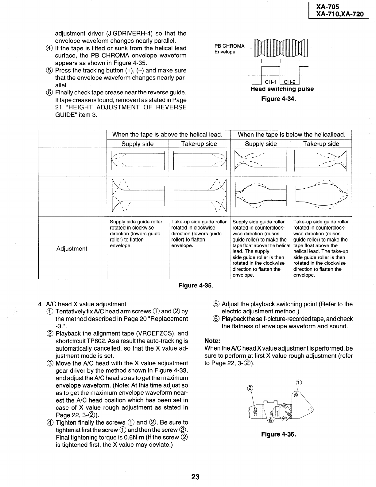
I- For X value adjustment
Adjust the X value, turning the geartype screwdriver.
Figure 4-33.
3. Tape run adjustment
Connect the oscilloscope to PB CHROMA envelope output test point, set oscilloscope sync to
EXT, trigger-input the PB CHROMA signal (head
switching pulse).
Rough adjustment of X value
Tentatively fixA/C head arm screws @ and @ by
the method described in Page 20 “Replacement
II
-3
Play back the alignment tape (VROATSV), and
shortcircuit TP802. As a result the auto-tracking is
automatically cancelled, so that the X value adjustment mode is set.
Move the A/C head with the X value adjustment
gear driver (JiGDRiVER-6) by the method shown
in Figure 4-33, and adjust the A/C head so as to
get the maximum envelope waveform. (Note:
When the A/C head is adjusted, adjust so that the
maximum envelop waveform is obtained nearest
the position of initial setting made in Page 20.)
@ Next, change the alignment tape to VROEFZCS
to playback. Press the tracking button (+), (-) and
change the envelope waveform from max to min
and from min to max. At this time adjust the height
of supply and take-up side guide roller with the
22
Page 23
adjustment driver (JiGDRiVERH-4) so that the
envelope waveform changes nearly parallel.
If the tape is lifted or sunk from the helical lead
surface, the PB CHROMA envelope waveform
appears as shown in Figure 4-35.
Press the tracking button (+), (-) and make sure
that the envelope waveform changes nearly parallel.
Finally check tape crease near the reverse guide.
If tape crease is found, remove it as stated in Page
21 “HEIGHT ADJUSTMENT OF REVERSE
GUIDE” item 3.
XA-705
XA-71 O,XA-720
PB CHROMA _
Envelope
Head switching pulse
Figure 4-34.
When the tape is above the helical lead.
I-
Supply side
Supply side guide roller
rotated in clockwise
direction (lowers guide
roller) to flatten
Adjustment
envelope.
4. A/C head X value adjustment
Tentatively fix A/C head arm screws @ and @ by
the method described in Page 20 “Replacement
II
-3
Playback the alignment tape (VROEFZCS), and
shortcircuit TP802. As a result the auto-tracking is
automatically cancelled, so that the X value adjustment mode is set.
Move the A/C head with the X value adjustment
gear driver by the method shown in Figure 4-33,
and adjust the A/C head so as to get the maximum
envelope waveform. (Note: At this time adjust so
as to get the maximum envelope waveform nearest the A/C head position which has been set in
case of X value rough adjustment as stated in
Page 22,3-a).
Tighten finally the screws @ and 0. Be sure to
tighten at firstthe screw @ and then the screw 0.
Final tightening torque is 0.6N.m (If the screw @
is tightened first, the X value may deviate.)
Take-up side
i:i”
Take-up side guide roller
rotated in clockwise
direction (lowers guide
roller) to flatten
envelope.
Figure 4-35.
0
@
Note:
When the A/C head X value adjustment is performed, be
sure to perform at first X value rough adjustment (refer
to Page 22,3-Q).
When the tape is below the helicallead.
Supply side
Take-up side
pq
\
\
\
.
/
/
\
Supply side guide roller Take-up side guide roller
rotated in counterclock- rotated in counterclock-
wise direction (raises wise direction (raises
guide roller) to make the guide roller) to make the
tape float above the helical tape float above the
lead. The supply helical lead. The take-up
side guide roller is then
rotated in the clockwise rotated in the clockwise
direction to flatten the direction to flatten the
envelope. envelope.
side guide roller is then
-_H
/
0
Adjust the playback switching point (Refer to the
electric adjustment method.)
Playback the self-picture-recorded tape, and check
the flatness of envelope waveform and sound.
Figure 4-36.
23
Page 24
XA-705
XA-71 O,XA-720
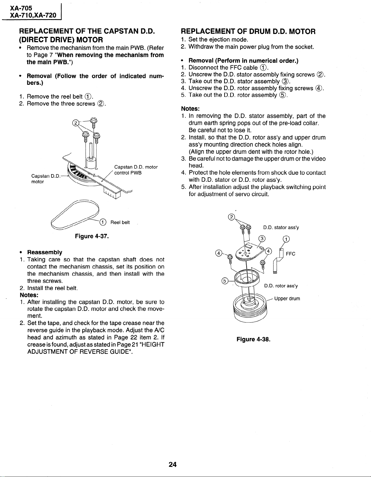
REPLACEMENT OF THE CAPSTAN D.D.
(DIRECT DRIVE) MOTOR
l Remove the mechanism from the main PWB. (Refer
to Page 7 “When removing the mechanism from
the main PWB.“)
l Removal (Follow the order of indicated num-
bers.)
1. Remove the reel belt 0.
2. Remove the three screws @.
motor
Capstan D.D.
motor
REPLACEMENT OF DRUM D.D. MOTOR
1 .
Set the ejection mode.
2 .
Withdraw the main power plug from the socket.
0
Removal (Perform in numerical order.)
1 .
Disconnect the FFC cable 0.
2 .
Unscrew the D.D. stator assembly fixing screws 0.
3
Take out the D.D. stator assembly 0.
4:
Unscrew the D.D. rotor assembly fixing screws @.
.
5
Take out the D.D. rotor assembly 0.
Notes:
1.
In removing the D.D. stator assembly, part of the
drum earth spring pops out of the pre-load collar.
Be careful not to lose it.
2
Install, so that the D.D. rotor ass’y and upper drum
ass’y mounting direction check holes align.
(Align the upper drum dent with the rotor hole.)
.
3
Be careful not to damage the upper drum or the video
head.
4.
Protect the hole elements from shock due to contact
with D.D. stator or D.D. rotor ass’y.
5.
After installation adjust the playback switching point
for adjustment of servo circuit.
Reel belt
Figure 4-37.
0
Reassembly
1
.
Taking care so that the capstan shaft does not
contact the mechanism chassis, set its position on
the mechanism chassis, and then install with the
three screws.
2. Install the reel belt.
Notes:
1. After installing the capstan D.D. motor, be sure to
rotate the capstan D.D. motor and check the movement.
2. Set the tape, and check for the tape crease near the
reverse guide in the playback mode. Adjust the A/C
head and azimuth as stated in Page 22 item 2. If
crease is found, adjust as stated in Page 21 “HEIGHT
ADJUSTMENT OF REVERSE GUIDE”.
D.D. stator ass’y
1
P
FFC
1. rotor ass’y
Upper drum
Figure 4-38.
24
Page 25
,
XA-705
XA-71 O,XA-720
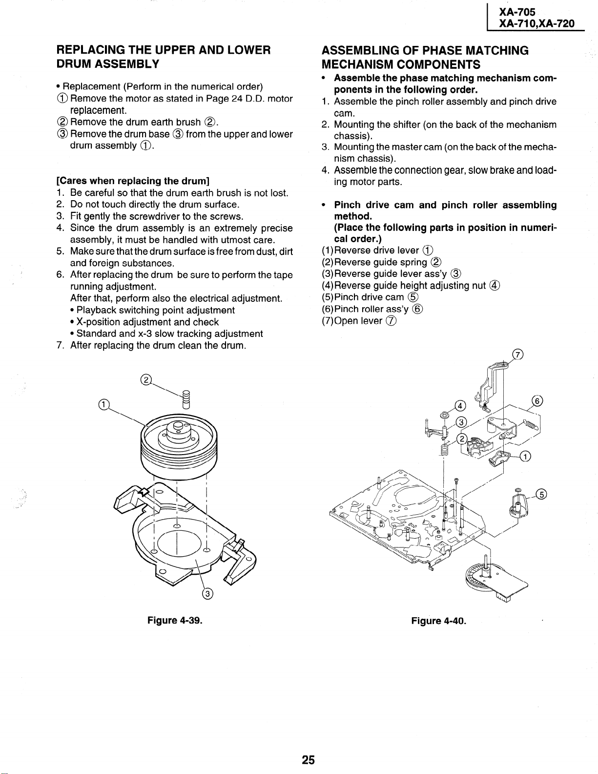
REPLACING THE UPPER AND LOWER DRUM ASSEMBLY
l Replacement (Perform in the numerical order)
@ Remove the motor as stated in Page 24 D.D. motor
replacement.
@ Remove the drum earth brush 8.
Remove the dru
0
drum assembly 0 .
[Cares when replacing the drum]
1.
Be careful so that the drum earth brush is not lost.
2 .
Do not touch directly the drum surface.
3
Fit gently the screwdriver to the screws.
4:
Since the drum assembly is an extremely precise
assembly, it must be handled with utmost care.
.
5
Make sure that the drum surface is free from dust, dirt
1
I
and foreign substances.
.
After replacing the drum be sure to perform the tape
6
running adjustment.
After that, perform also the electrical adjustment.
l Playback switching point adjustment
l X-position adjustment and check
l Standard and x-3 slow tracking adjustment
7.
After replacing the drum clean the drum.
m base
@ from the
upper
and lower
ASSEMBLING OF PHASE MATCHING MECHANISM COMPONENTS
0
Assemble the phase matching mechanism components in the following order.
1 .
Assemble the pinch roller assembly and pinch drive
cam.
2.
Mounting the shifter (on the back of the mechanism
chassis).
3 .
Mounting the master cam (on the back of the mechanism chassis).
4.
Assemble the connection gear, slow brake and load-
ing motor parts.
0
Pinch drive cam and pinch roller assembling
method.
(Place the following parts in position in numerical order.)
(l)Reverse drive lever @
(2)Reverse guide spring @
(3)Reverse guide lever ass’y @
(4)Reverse guide height adjusting nut @
(5)Pinch drive cam @
(6)Pinch roller ass’y @
(7)Open lever 0
Figure 4-39.
Figure 4-40.
25
Page 26
XA-705
XA-71 O,XA-720
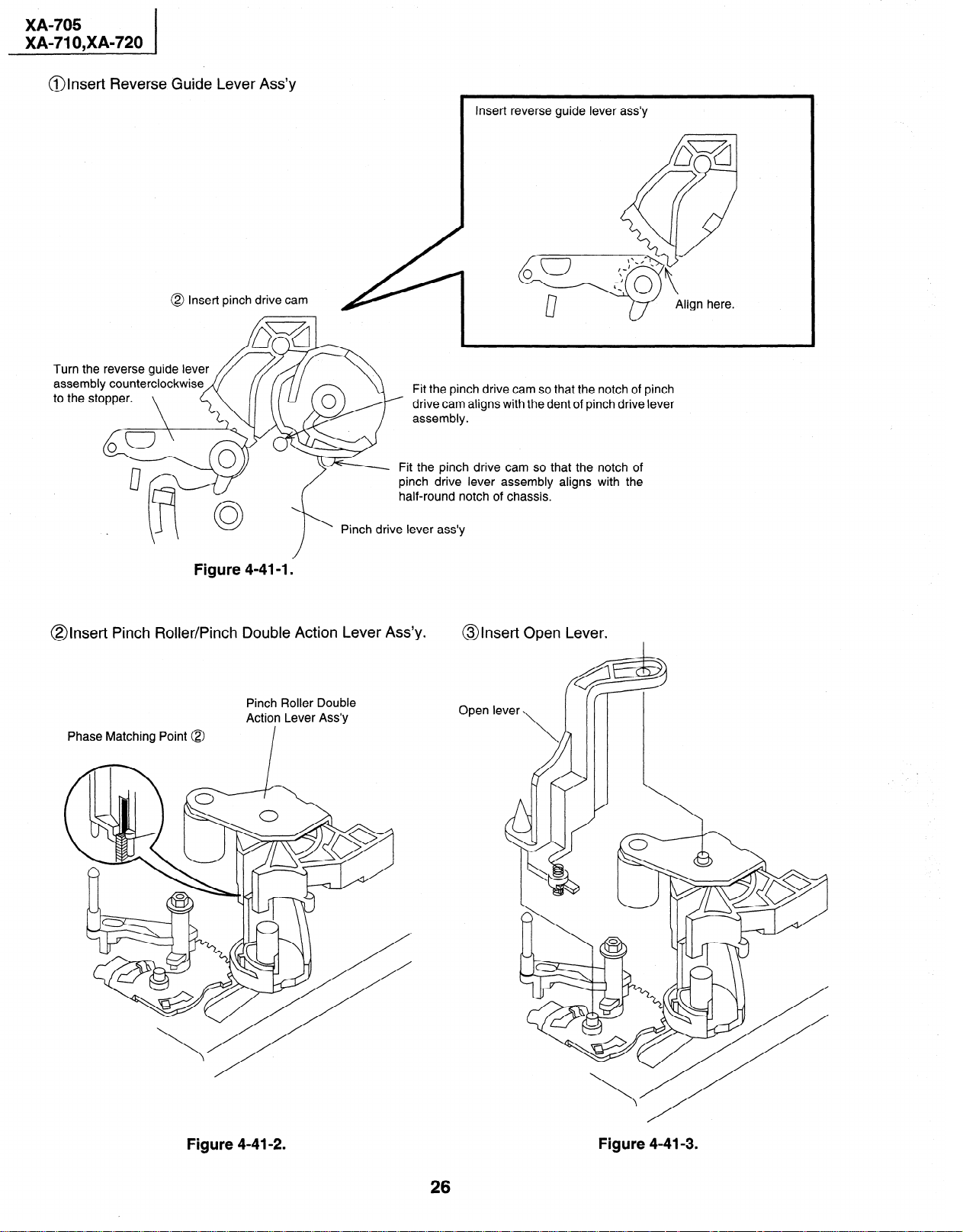
@Insert Reverse Guide Lever Ass’y
@ Insert pinch drive cam
Insert reverse guide lever
Fit the pinch drive cam so that the notch of pinch
drive cam aligns with the dent of pinch drive lever
- Fit the pinch drive cam so that the notch of
pinch drive lever assembly aligns with the
half-round notch of chassis.
ass’y
Pinch drive lever ass’y
Figure 4-41-l.
@Insert Pinch Roller/Pinch Double Action Lever Ass’y.
Pinch Roller Double
Action Lever Ass’y
Phase Matching Point @
@Insert Open Lever.
G3
Open lever
\
R@
Figure 4-41-2.
Figure 4-41-3.
Page 27
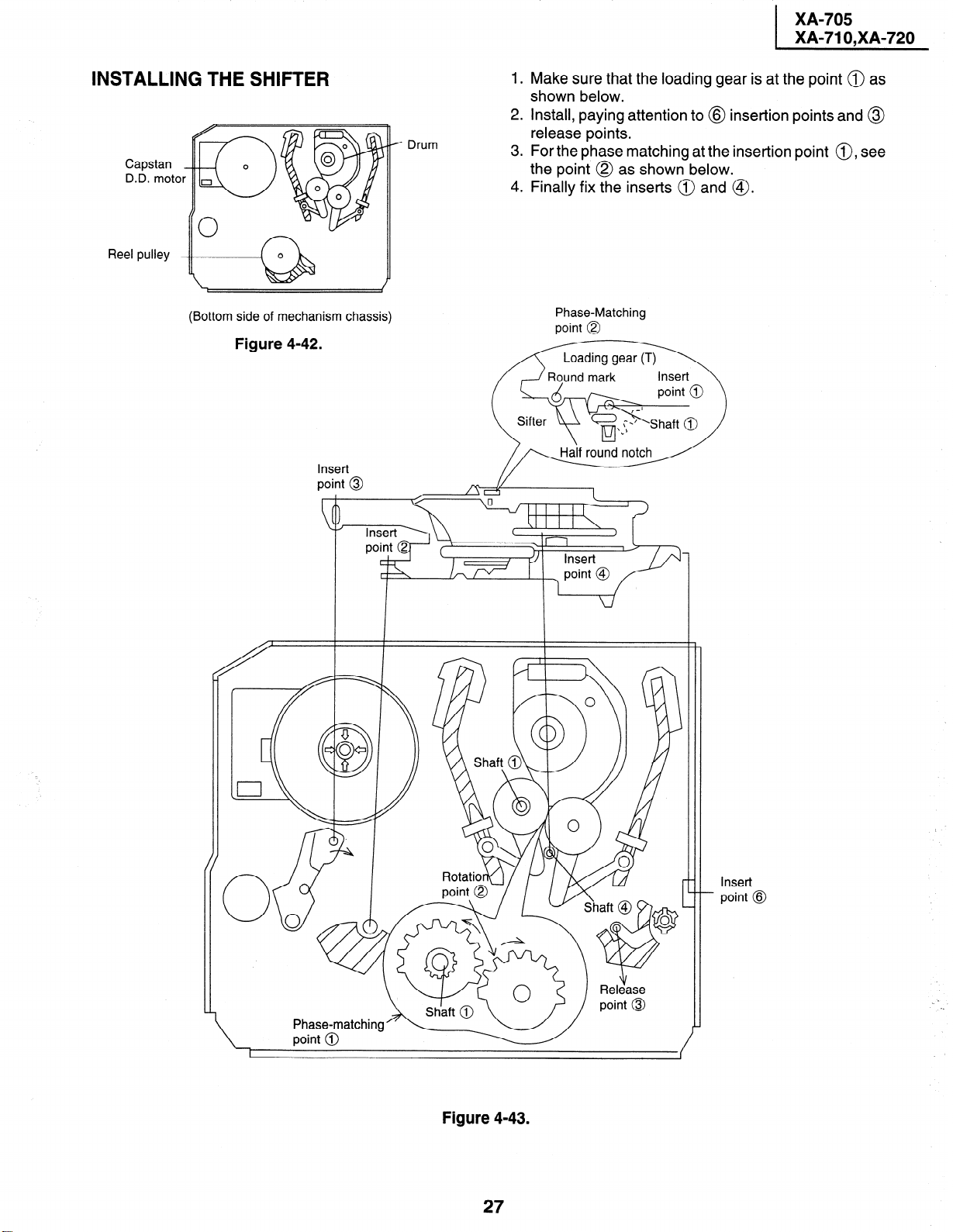
INSTALLING THE SHIFTER
._
Capstan
D.D. moto
Reel pulley
Drum
/ iK&w*o
1.
Make sure that the loading gear is at the point @ as
shown below.
2.
Install, paying attention to @ insertion points and @
release points.
.
3
For the phase matching at the insertion point 0, see
the point @ as shown below.
4.
Finally fix the inserts @ and @.
(Bottom side of mechanism chassis)
Figure 4-42.
Insert
point @
Phase-Matching
point @
notch
-/Y I
/ \ / -I
Rotatior)(\l /
Figure 4-43.
27
Insert
- point @
Page 28
XA-705
XA-71 O,XA-720
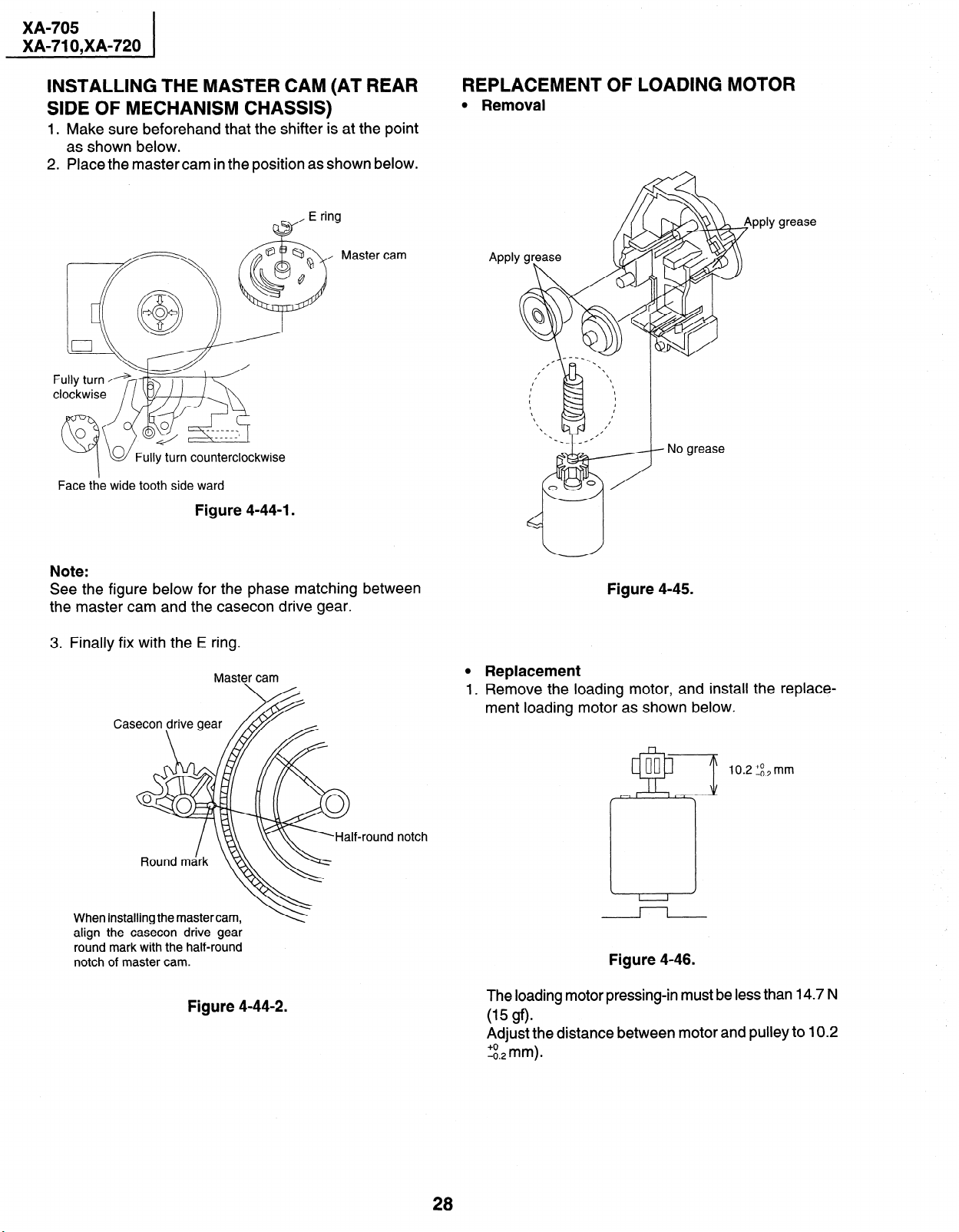
INSTALLING THE MASTER CAM (AT REAR SIDE OF MECHANISM CHASSIS)
1. Make sure beforehand that the shifter is at the point
as shown below.
2. Place the master cam in the position as shown below.
E ring
w
Master cam
Face the wide tooth side ward
Figure 4-44-l.
REPLACEMENT OF LOADING MOTOR
l Removal
lly grease
PP
APPl
Note:
See the figure below for the phase matching between
the master cam and the casecon drive gear.
3. Finally fix with the E ring.
Master cam
nd notch
When
installing the master cam,
align the casecon drive gear
round mark with the half-round
notch of master cam.
Figure 4-44-2.
Figure 4-45.
l Replacement
1, Remove the loading motor, and install the replace-
ment loading motor as shown below.
10.2 “_& mm
-II
Figure 4-46.
The loading motor pressing-in must be less than 14.7 N
(15 gfb
Adjust the distance between motor and pulley to 10.2
28
Page 29

ASSEMBLY OF CASSETTE HOUSING
1. Drive Gear and R Drive angle ass’y
grease
Figure 4-47.
2. Synchro Gear, Drive Gear L and Drive Gear R
Top surface should be fre
Drive angle
Drive gear R
. Frame
Figure 4-48.
29
Page 30

XA-705
XA-71 O,XA-720
5. ELECTRICAL ADJUSTMENT
Notes:
l Before the adjustment:
Electrical adjustments discussed here are often required after replacement of electronic components and mechanical parts such as video heads.
Check that the mechanism and all electric components are in good working condition prior to the adjustments,othetwise
adjustments can not be completed.
l lnstrliments required:
l Color TV monitor
l Audio signal generator
l Blank video cassette tape
l Screwdriver for adjustment
l RF sianal aenerator
l Dual-trace oscilloscope
l AC milli-voltmeter
l Alignment tape (VROATSV, VROABZGS)
l Color bar generator
*1
*2
*3
*4
*5
*6
*7
*8
. . .
TP201-204
R163
. . .
. . .
TP161-163
. . .
TPI 68-169
. . .
TPI 64-165
. . .
TP801
R724
. . .
. . .
TP802
Figure 5-l.
30
Page 31

XA-705
XA-71 O,XA-720
SERVO CIRCUIT ADJUSTMENT
5-l ADJUSTMENT OF HEAD SWITCHING
POINT
Measuring
Instrument
Mode
I
Cassette
I
Test Point VIDEO OUT jack to CH2
Control ’ R724 Head switching point
Specification
I
1.
Remove the front panel and play the alignment tape.
2.
Connect a dual-trace oscilloscope to the VIDEO OUT
jack and TP202 (Sig.) and TP203 (GND).
(Trigger the oscilloscope with the head switching
pulse on TP202.)
.
3
Playback the alignment tape, and then short circuit
between TP802 on the main PWB, and press both CH
button (+) and CH button (-) at same time.
4.
Adjust R724 so that the leading edge of.the head
switching pulse is 5.5H (lines) ahead of the vertical
sync as shown in Figure 5-2.
.
Cancel the short circuited.
5
Dual-trace oscilloscope
Playback
I
Alignment tape (VROABZGS)
I
TP202 (Sig.)-TP203 (GND) to CHI
adjustment control
5.5+ 0.5H (lines)
I
5-2 ADJUSTMENT OF FV (False Vertical
Sync) OF STILL PICTURE
Measuring
Instrument
Mode
I
Cassette
I
I
I
Control
Specification
1. Play a cassette which was recorded by the unit in SP
mode.
2 . Press the PAUSE/STILL button to freeze the picture.
. Look at the monitor screen and adjust (+) or (-)
3
TRACKING buttons so that the vertical jitter of the
picture is minimized.
4.
Play and freeze the self-recorded tape in EP mode
and make sure vertical jitter of the picture is not
noticeable.
Notes:
1. The FV goes back to the it’s initial state when the unit
is put into the system controller reset mode due to
power failure, etc.
In this case, preset the FV once again.
2. Self-recorded tape is a cassette whose program was
recorded by the unit being adjusted.
Color TV monitor
Playback still
I
Self-recorded tape (SP mode)
(See Note 2 below)
Tracking control buttons(+) or (-)
No vertical jitter of picture
I
5-3 CHECKING OF OFF TRACK
CH-2
VIDEO
CH-1
HEAD
SWITCHING
PULSE
CH-1 : 1 V/dev 50psec/dev
CH-2: 2V/dev 50psec/dev
I
I- 5.5+0.5H (lines) d
I I
8 I
Figure 5-2.
V-sync.
.
Measuring
Instrument
Mode
I
Cassette Self-recorded tape (EP mode)
Control I Tracking control buttons(+) or (-)I
I
Specification
I
1. Play a cassette which was recorded by the unit in EP
mode.
2. Short circuit between TP802 on the main PWB, and
press both CH button (+) and CH button (-) at same
time.
3. Press the tracking buttons (+) and (-) 20 times each
to bring the tracking off center. Make sure that:
1) There is nothing unusual on the playback screen.
2) There is nothing unusual in the Hi-Fi sound (for the
Hi-Fi models only).
4. Cancel the short circuit.
Note:
Self-recorded tape is a cassette whose program was recorded by the unit being adjusted.
Color TV monitor
Playback
I
(See Note below)
No Poor picture and Hi-Fi sound
I
I
I
31
Page 32

XA-705
XA-71 O,XA-720
I
I
MTS CIRCUIT ADJUSTMENT.
(Hi-Fi MODELS ONLY)
5-4 ADJUSTMENT OF SIF-INPUT LEVEL
Measuring
Instrument
Mode
I
Input Signal 1 RF CH-11 (at 1 kHz lOO%MOD.) 1
I
Test Point
I
Control
I
Specification
I
1. Feed the RF signal CH-10 (at 1 kHz lOO%MOD.) to
antenna terminal.
2. Connect the AC milli-voltmeter to AUDIO OUT (L)
.
jack
3. Adjust RI 41 (S-IF ADJ.) so that the AC milli-voltmeter
reads -3 dBs.
5-5 ADJUSTMENT OF FILTER
AC milli-voltmeter and RF signal
generator.
E-E
I
AUDIO OUT (L) jack
I
RI41 (S-IF ADJ.)
I
-3 k 2dBs (1.2-2.OVp-p)
I
5-6 ADJUSTMENT OF STEREO VCO
I
I
I
I
Measuring
Instrument
Mode
Input signal
Test point
Control
Specification
I
1. Make the short circuited to TPI 62 (Sig.)-TPI 63 (GND).
2. Connect the AC milli-voltmeterto TPI 68(Sig.)-TPI 69
(GND).
3. Make a note of the level of TPI 68 (Sig.)-TPI 69 (GND).
4. Feed the 15.734kHz at 50mVrms signal to the
TPI 61 (Sig.)-TPI 63 (GND).
5. Adjust RI 62 (STEREO VCO ADJ.) so that the levels
for non signal inputed STEP 3. and inputed be just the
same.
6. When the 15.734kHz at 50mVrms signal is fed confirm the display “STEREO” is indicated on OSD.
AC milli-voltmeter
E-E
15.734kHz at 5OmVrms
TP168 (Sig.), TP169 (GND)
RI62 (STEREO VCO ADJ.)
I I
Measuring
Instrument
Mode
I
Input Signal
I
Test Point
I
Control
I
Specification
I
1. Make the short circuited to TPI 62 (Sig.)-TPI 63 (GND).
2. Connect the AC milli-voltmetertoTP164 (Sig.)-TPI 65
(GND).
3. Feed the 22.9kHz at 245mVrms signal to the
TPI 61 (Sig.)-TPI 63 (GND).
4. Adjust RI63 (FILTER ADJ.) so that the AC millivoltmeter reads minimized.
AC milli-voltmeter
E-E
I
22.9kHz at 245mVrms
I
TP164 (Sig.), TP165 (GND)
I
RI63 (FILTER ADJ.)
I
Minimized
I
I
I
I
I
I
5-7 ADJUSTMENT OF STEREO
SEPARATION
Measuring Dual AC milli-voltmeter and RF
Instrument
Mode
I
Input signal RF CH-10 (300Hz and 3kHz 30%
Test point
Control
Specification
I
1. Feed the RF signal CH-10 (300Hz and 3kHz 30%
modulation) to antenna terminal.
2. Connect an Dual AC milli-voltmeter to left channel
and right channel output terminales.
3. Set the audio signal to 300Hz and the modulation
factor to 30% (Left channel only) and adjust RI64
(SEPARATION (1) ADJ.) so that the difference between left channel and right channel outputs becomes maximized.
4. Set the audio signal to 3kHz and the modulation factor
to 30% (right channel only) and adjust RI65 (SEPA-
RATION (2) ADJ.) so that the difference between left
channel and right channel outputs becomes maxi-
mized.
5. Repeat STEP 3. until obtain a specification +24 db.
signal generator.
E-E
I
modulation)
AUDIO OUT (L, R) jack
RI64 (SEPARATION (1) ADJ.)
R165 (SEPARATION (2) ADJ.)
Maximized
I
I
32
Page 33

I
.
.
.
.
1
A
CASSETTE INSERTION ++ STOP
End
Cassette is ejected and loading
?-
Insert cassette.
motor stops.
Y
sensor close.
Start
Double action rack slides.
Loading motor turns in reverse
in normal
Loading motor starts
direction and master cam turns
counterclockwise.
direction and master cam turns
inserting *
Cassette
Does mechanism position SW. NO
counter clockwise.
(Cassette is judged
caught halfway.)
come off within 2.5 sec.?
YES
NO
Are end sensors at low level
(Cassette LED or some other part
- is judged defective.)
before cassette insertion ?
_
YES
c
Drum motor starts.
1
Tape is loading.
Pinch roller comes into contact.
Cam switch is at PB position.
r --
*
Full-
loading
1
Loading motor stops.
Unloading
NO -
- +
I I 1
YES
Does drum FG pulse output ?
I
End
C.
Cam switch is at
MECHANISM OPERATION FLOWCHART
* This flowchart describes the outline of the mechanism’s operation, but does not give its details.
F mechanical timing
Cam graph E
25
Mode check
0
\
/
Cam mark
I
L
20-
Mode detection outside
(D709 SW 8)
15- I lo-
Mode detection
(D708 SW A)
5-
CL STOP FF
300 360
PB SLW
II I
I I
I
UL PU(LD) VSR PB
I II
60 120 180 240
CA/END
CSEJ
VSR
FUl
IULl
1
EJ
I I
I
0 IO 11 111; 0 1 101 I 0 1 I 0 I 1 lo
;
f I1
!
I ; 1 0 11 I 1 11 0
0” ’
open 0
Mode
Cam switch
Rotation angle 0 188 218 252 269 293309 325
S sensor 1 :lI 0 Il]lorO
Modedetection outside 0
’ SenSor close 1
Modedetection inside
Page 34

+
VSR + PLAY
PLAY + VSR
Press PLAY Key.
I
Press REW key.
Loading motor turns counter-
clockwise and master cam
turns clockwise.
Pinch
roller *
Capstan motor turns
counterclockwise. PB speed.
Release pinch roller.
releasing
reverse direction.
Capstan motor in turns
Idler
swinging
Loading motor turns clockwise.
Pinch
roller =
Press pinch roller.
pressing
NO
I
f
+
i
+
t
1 YES
End
f
Unloading
Loading motor stops.
speed.
Is take-up reel sensor signal
outputted ?
Cam switch is at VSR
position.
I
Set capstan motor to search
‘
I
PLAY + STILL
c
STOP + REC/PLAY
Press STILL key.
1
t
I
I
End
Capstan motor stops.
I
Press STOP key.
I
I
t
I
I
I
I
I
1
I
t
I
I
t
1
1
Loading motor stops.
Cam switch is at STILL
Slow brake comes into
I-
contact with capstan motor.
I
I
master cam turns clockwise.
Loading motor turns in
I
counterclockwise direction and
I
I
position.
I
I
I
1
I
Capstan motor stops.
I
I
End
REC/PLAY + STOP
--
Slow brake
pressing l
Press FF key.
I
I
t
Set capstan motor to search
speed.
I
Capstan motor turns
Picture appears.
Is take-up reel sensor signal
outputted ?
1 YES
End
I
I
Unloading
I
PLAY+ VSi=
Page 35

I
t
STOP -+ CASSETTE EJECT
Press EJECT key.
Loading motor turns in clockwise and master cam turns
counterclockwise.
Tape
1
Capstan motor turns in reverse direction.
unloading
I
i
Cam switch is at UL position.
Loading motor stops.
I
A
Capstan motor turns
clockwise.
NO )
Does 4 supply reel
pulses output ?
iYES
_
Capstan motor turns
counterclockwise in about
2 seconds.
I
I
I
*
I
Capstan motor turns
clockwise.
i
Loading motor turns
clockwise.
I
Eject position.
Cam switch is at
1
L
Cassette
eject
Capstan motor
stops.
jl
1
4
STOP + FF/REW
Press STOP key.
I
Loading motor turns counter-
clockwise.
End
Press FF/REW key. 1
I
I
FF/REW + STOP
+
End
I I
Brake
FF/REW
operation
function
Page 36

system in trouble.
NO, Voltage supply
I
2. REC/PLAY FAILURE (MODE RELEASE)
I
f
* supply at loading
NO Does voltage
Is the master cam NO_ Does loading
at PB position ? motor operate ?
motor ?
smoothly through
cam switch ?
YES
r
Loading motor
control system
in trouble.
1 YES 1 YES
1 YES
t
Modes changing
f
system in trouble.
vcc 5v supply ?
NO Does Vco 12V and NO Voltage supply
Does capstan
motor turn ?
YES
YES
.
Replace the
capstan motor.
I
I I
1
YES
1
ass’y and reel disk
1 Check main PWB.
I
MECHANISM TROUBLESHOOTING
Press FF key.
1. FF/REW FAILURE (NO TAPE WINDING)
I
No+ Does loading
Is master cam at
FF position ? motor operate?
YES
YES
1
Modes changing
t
Reolace it.
damaged.
smoothly through
I
Mode sensor
system in trouble
I
1
or master cam
1 malpositioned.
system in trouble.
vcc 5v supply ?
*
NO Does Vco 12V and NO Voltage supply
Does capstan
motor turn in FF (or
I
I
No Replace the idler
Are idler wheel
ass’y and reel disk
wheel ass’y.
H
YES
in mesh ?
I
I
YES YES
REW) direction ?
I
Replace the reel
sensor.
NO
H
Does the pulse
output from reel
sensor ?
,an mo
Page 37

Replace cassette control ass’y.
Replace damaged one with new one.
Check pinch roller drive cam, pinch roller
I
b
drive lever and reverse guide for their actions.
4. UNUSUAL SOUND IN EACH MODE
I
I
insertion and ejection mode
4-i) Unusual sound in cassette
YES
Is unusual sound heard during
t-
NO
I
cassette countrol running ?
Is unusual sound heard with pinch yES )
roller lever going up or down ?
I I
Is unusual sound heard during
loading/unloading ?
YES
I
L
I-----l
I
Replace loading motor block.
I
I
3. WINDING FAILURE AT VSR
I
t
Go to 2. REC/
* PLAY FAILURE
NO
Is Playback
function normal ?
routine.
I
I
YES
I
I
Press REW key.
I
PLAY FAILURE
Go to 2. REC/
NO
Does master cam
shift to VSR
routine.
--i
YES
position ?
NO
I
Are idler wheel
Replace idler
ass’y and supply
) gear ass’y.
reel disk in mesh ?
YES
Replace limiter
pulley ass’y.
L I
Replace reel
sensor.
NO
Does pulse output
from reel sensor?
--i
I I
YES
I
I
Check main PWB.
Page 38
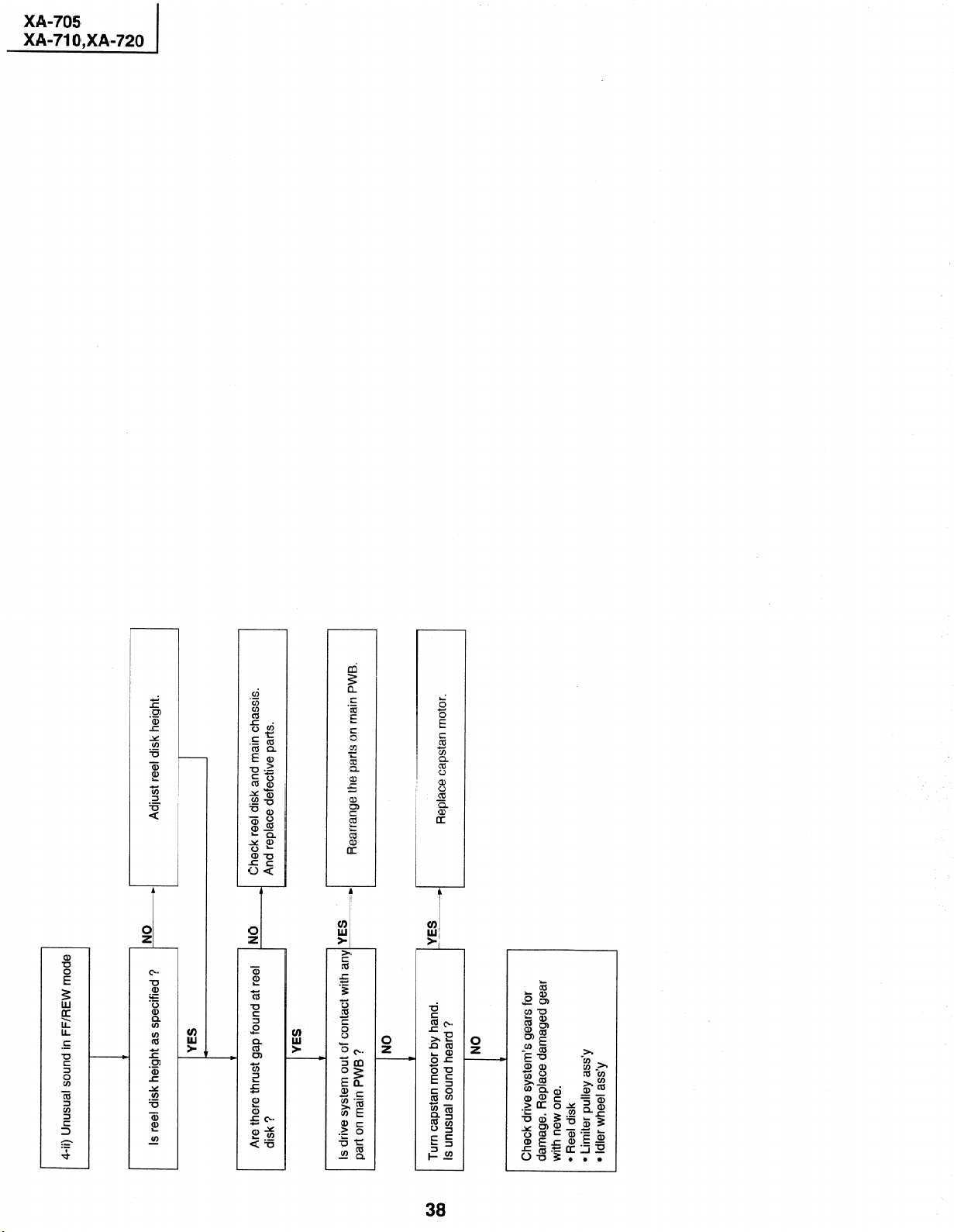
I
I
4-ii) Unusual sound in FF/REW mode
Adjust reel disk height.
+
NO
Is reel disk height as specified ?
YES
I
I
t
I
Check reel disk and main chassis.
And replace defective parts.
I
NO
t-i
I
Are there thrust gap found at reel
disk ?
I I
YES
Rearrange the parts on main PWB.
I
I
Is drive system out of contact with any-YES
part on main PWB ?
L
NO
Replace capstan motor.
YES
Is unusual sound heard ?
Turn capstan motor by hand.
NO
c
,
Check drive system’s gears for
damage. Replace damaged gear
with new one.
l Reel disk
l Limiter pulley ass’y
l Idler wheel ass’y
Page 39

Replace D914, Q903 and Q904.
FLOW CHART NO.4 POWER TROUBLESHOOTING(4)
Replace IC901
L
Check AT 5V line.
I I
1 The flourescent display tube fails to light up. 1
FLOW CHART NO.5 TIMER(l) TROlJBLESHOOTING
Check negative voltage line and
* power circuit:
I
Check FL801 and IC801.
I
P-----l
1
IYES
iYES
Check power circuit and peripheral
--(of
Check for cracks on the fluorescent
) display tube.
Replace IC801.
I
No power
Check the D914, Q903 and Q904.
I I
I
ho
Replace fuse.
See FLOW CHART NO.2 POWER
TROUBLESHOOTING(2)
i
t
I
Check short circuit or leak of T901
~~O~~*.OY-.lll
Check primary circuit.
*
NO
1
1 1 I
Check primary circuit, Q901, Q902,
C907 thru C909 and C930.
Check each rectifier circuits and
* short-circuit of secondary circuit.
Check Q905, P-FAIL(L)
) signal line and etc.
Is there supply voltage of 5V feed at
pin (I 8) of IC801?
1 In case of Fuse(F901) blown out. 1
Is there 4.0MHz oscillation at
Check short-circuit or leak of D905
pins (19) and (20) of IC801?
I
Is there filament voltage supply
between pins (l)/(2) and (31)/(32)
of the flourescenbdisplay tube?
Also negative voltage applied
between these pins and GND.
1 In case of abnormal noise(sound) 1
Does the fluorescent display tube
11%
FLOW CHART NO.1 POWER TROUBLESHOOTING(l)
1
Replug it a few minutes later.
Unplug the AC power cord.
I
. 1
IVES
Is the fuse good?
I
1 YES
Is AT 5V line normal?
Are AT 44V, AT 12V, AT-24V, AT 18V No
and filament voltage lines normal?
Does “H” level applied at pin (1) of NO
1 YES
IC701?
Check IC701 (system control circuit)
and cam switch circuit.
FLOW CHART NO.2 POWER TROUBLESHOOTING(2)
Replace F901, Q901 and Q902, check
0921 -D925 as a result of check, if thru D909, 0918 and secondary
poor, replace at the same time. circuit.
FLOW CHART NO.3 POWER TROUBLESHOOTING(3)
Page 40

XX
DD
44
A0
I
*o O1
X
D
b
0
FIX or replace the cassette housrng.
bb
1
I
Check start sensor cover.
b
Check start sensor and all the way
Check IC701 and all the way up
W
Check IC705.
to pin (2) of IC705.
)
A cassette tape is not take in.
c
FLOW CHART NO.8 CASSETTE CONTROL TROUBLESHOOTING(l)
Is cassette housing distorted? YES ’
I
Check switch contact.
I
ANO
I
NO
Does start sensor cover open
when the cassette tape is inserted?
IYES
No
Does pin (79) of IC701 change from
“H” to “L” level when the cassette
NO
.
iYES
tape is inserted?
Does pin (2) of IC705 go to a “H”
(about 1.7V) level when the
cassette tape is inserted?
Does pin (7) of IC705 change to NO
inset-ted?
about IOV when the cassette tape is
1 YES
Is the specified voltage applied at the NO
loading motor terminal when the
cassette tape is inserted?
I
1 YES
Replace loading motor.
I
Replace R/C receiver.
)
I
NO
1
Key-in input is not received.
FLOW CHART NO.6 TIMER(Z) TROUBLESHOOTING
i
Does the key switch make good
contact?
and switches for poor soldering.
I
* Check all the terminals of IC801
Check lines of key in and scan out.
b
Replace infrared R/C unit as
required.
hi ( Check AT 5V and GND lines.
R/C receiver and pin (5) of IC701.
b
+ Check between Vout terminal of
I
YES
I
IYES
is there a short in the scan outs or
I
key inputs?
iNO
No
Are pulses received at pins (27) thru f (29) of IC801 when the keys are
IYES
activated?
FLP clock, FLP CS and key data.
Check IC801, IC701 and FLP data,
No operation is possible from the infrared remote control.
I
FLOW CHART NO.7 INFRARED R/C TROUBLESHOOTING
Does infrared R/C unit function?
I
I
1 I
I
IVES
I
NO
Is there supply voltage of 5V feed at
Vdd terminal of R/C receiver?
iYES
NO
Is “L” pulse sent out Vout terminal
R/C unit is activated?
of R/C receiver when the Infrared
IYES
NO
1s “L” pulse received at pin (5) of
lC701 when the Infrared R/C unit
is activated?
AYES
Replace IC701.
Page 41

I
I
1
I
I
I
See FLOW CHART N0.12.
(CAPSTAN MOTOR TROUBLE
The cassette tape fails to eject.
I
c
FLOW CHART NO.10 LOADING MOTOR AND EJECT TROUBLESHOOTING
Does the capstan motor start when
the EJECT button is pressed?
SHOOTING)
) Check reel disk and reel drive unit.
NO
IYES
Does the take-up reel disk turn when
r
IYES
the capstan motor is running?
Check take-up reel sensor and all the
NO
Does pulses supply at pin (2) of
way up to IC701.
*
IC701 when the take-up reel disk is
I ,
IYES
turning?
I
Check pin (92) of IC701.
*
N()
Is a “H”(about 1.7V) level supply at
I
pin (4) of IC705 when a reel pulse
has been inputted?
I I
1 YES
r
Check IC705.
I 1
F-i
I
Does voltage (about IOV) sent out
pin (5) of IC705?
I I
1 YES
Check between IC705 and all the
NO
Is there specified voltage supply at
the loading motor terminal? way up to the loading motor.
I r
1
1 YES
I
Replace loading motor.
NO
IYES
Dose the loading motor run?
Replace cassette cam, gear and etc.
I
up to IC701.
Check start sensor and all the way
A cassette tape is taken in, but ejected at once.
I
FLOW CHART NO.9 CASSE-ITE CONTROL TROUBLESHOOTING(2)
Does the Start sensor pulse at pin NO
(79) of IC701 change from “L” to “H”
level when the cassette tape is
IYES
1 inserted?
) Check end sensor and all the way
Does the end sensor pulse at pin(85) ,No
up to IC701.
of IC701 change from “L” to “H” level
when the cassette tape is inserted?
I
1 YES
I
Check cam switch and all the way
Does the master cam mode shifter
operate normally when the cassette
1-i up to IC701.
tape is inserted?
Page 42

I
I
Check IC701.
_______-____*
-I r
--.-
The capstan motor fails to run.
v
FLOW CHART NO.12 CAPSTAN MOTOR TROUBLESHOOTING
Is the voltage (more than about 2 6V ’ NO
DC) given out pin (32) of IC701.
I
Check PC 5V line.
-. __--_.__.____-
i NO
,
1 YES
Is there supply voltage of 5V ttsec! & / __ _ _
pin (8) of MC connector?
; I----- --
1 YES
---__ _ .- _ .-
I
Check between the MC connector
-_-
______ _ i----- - --------------+I z;gW$e ;Nay up to pin (32)
,
Does voltage (more than 2.6V LX !
connector 1.6-2.7V?
I
1
LYES
feed at pin (5) of MC connectrrr?
I --- -- -
I
Replace capstan motor
I
I___--__ .__.. !
I
Check IC801 and IC701, and all
,
) the way to them.
No power is turned on.
I
t
FLOW CHART NO.1 1 SYSTEM CONTROL TROUBLESHOOTING
tN0
IYES
1 YES
Check IC701.
IYES
Check Q951 and all the way up thru
I
to Q952.
I
I
I
I
1 YES
I
J I
Q951? Check Q951 and the AT 5V line.
Does key data pulses Supply at pin NO
(15) of IC701, respectively?
Are there FLP data pulses, FLP clock pulses and FLP control ready pulses supply at to pins
(24), (23) and (22) of IC801, respectively?
I I
Does power control (H) signal at pin , No
(94) of IC701 change from “L” to “H”
level?
Does the base of Q951 change from NO
about 2.OV to 5.OV?
I I
Is 5V sent out of the emitter of
I
Check penperal circuits for poor
I
11
Page 43

Replace IC701.
xx
No head switching pulse. 1
I
FLOW CHART NO.15 HEAD SWITCHING PULSE TROUBLESHOOTING.
Is the drum motor rotating?
Are there drum PG M.M. signal at
~---~-~- pin (81) of IC701?
signals at pins (66) and (65)
Are there drum PG and drum FG
of IC701, respectively?
Check lines between AD connector _
---_.-
YES
Are there drum PG and drum FG
r-
signals at pins (3) and (5) of
_[ and IC701. 1
I
AD connector?
Check drum motor and the betweerl
1 AD and ME harness. ______
I
Check IC701.
I
*
The drum motor fails to run.
I
c
FLOW CHART NO.13 DRUM MOTOR TROUBLESHOOTING(l)
Is the voltage more than about 2.6V NO
DC given out of pin (31) of IC701?
1 YES
Check between pin (31) of IC701
) and all the way up to pin (1) of ME
Is the voltage more than about 2.6V NO
applied at pin (1) of ME connector?
Check AT 12V line.
connector.
b
NO
I VEC
.
Is the supply voltage of 12V feed to
1 YES
pin (4) of ME connector?
Replace drum motor.
Check drum motor.
I I
The drum motor runs only for a few seconds.
FLOW CHART NO.14 DRUM MOTOR TROUBLESHOOTING(2)
Is drum PG signal given out of pin
(5) of ME connector?
I
1 YES
I 1 t 1
Check between pin (5) of ME
connector and all the way up to
*
Is drum PG signal given out of pin No
pin (66) of IC701.
(66) of IC701?
,
1 YES
Check IC701 and readjust R724.
) (HEAD SW POINT control)
Is drum PG M.M. signal given to pin NO
(81) of IC701?
1 YES
I I 1 1
Check IC701.
*
NO
Is H.SW. pulse given out of pin (23)
1 YES
Replace IC701.
of IC701?
Page 44

xx
DD
Check peripheral circuit of X701.
I
Drum servo does not function.
Is there 14.2MHz oscillation at pins
(37) and (38) of IC701?
I
FLOW CHART NO.16 DRUM SERVO TROUBLESHOOTING
YES
‘
c
In REC mode
I
1
1
N
10
Is there reference signal (V-SYNC)
at pin (50) of IC701?
YES
--i
I
I
See FLOW CHART N0.15. (HEAD
(C770, C771 and R770)
Check composite-sync signal line.
SHOOTING.)
* SWITCHING PULSE TROUBLE
NO
Replace IC701.
NO
I
I I
I
H
I
I
Replace IC701.
NO
Is pin (31) of IC701 in high
NO
I I
t--i
I
I
H
I
I
In PB mode
5
t
of IC701 present?
NO, Is there drum FG signal at pin (65) 4
1 YES
,
Is there head switching pulse at pin
(23) of IC701 present?
Does drum error output at pin (33)
Check drum FG signal line.
1 YES
of IC701?
I
.
I
4 YES
Does drum control voltage supply
at pin (1) of ME connector? impedance?
I
Check harness between AD and ME.
I I I
Page 45

L
Capstan servo does not function.
2
0
Check composite- No Does the V-SYNC
Only REC mode inoperative
I I I .-I
PB mode
Are REC and/or
I inoperative?
pin (50) of IC701?
signal appear at
Sync signal line.
H
(C770-1, R770)
Does the capstan
) FG signal appear
14.2MHz at
Is there oscillated YES
lC701?
) at pin (67) of
INO
Check between
capstan FG signal
line and the
circuit of X701.
IYES
AC-MC harness.
I 1
t YES
Is there capstan
(34) of IC701?
) error signal at pin
NO
Replace IC701.
Replace AA-MH
harness
Replace IC701.
,’
I ’
FLOW CHART NO.17 CAPSTAN SERVO TROUBLESHOOTING
Only PB mode inoperative
1
0
YES
signal appear at
pin (76) of IC701?
(TP204)
NO
l_
Does PB CTL
+
Is AA-MH harness NO
I I I 1
good?
1 YES
’ NO
Does A/C head _
oprate normally?
Adjust the height _
of the A/C head.
Page 46

I
@ Check the line between the front/rear video input
@ External input mode
l
- NO
terminal and IC201 pin (3011.
@ (Only for XA-710)
YES
Check the line between SC2301 pin (8) and IC201
pin (28).
Check the line between the U/1/ tuner pin (25) and
@ U/V tuner mode
IC201 pin (31).
Is there picture signal output at IC201 pin (52)?
NO
4
& YES
Does 5V supply at IC201 pins (12), (61) and (EIO)?
NO
~_~
4 NO
Check Q251 periphery.
Does serial data clock signal supply at IC201
pins (63) and (62)?
4
4 NO
Check the line between ICZ!Ol pins (63) and
(62) and IC701 pins (56) and (57).
NO
4 NO
Check the AT 5V line.
FLOW CHART NO.18
Picture E-E does not appear.
Is there picture signal at into IC201 pins (28), (30) and (31)?
Is there picture signal input IC701 pin (49)?
YES
Check the line between IC201 pin (52)
and IC701 pin (49).
Is there picture signal output IC701 pin (47)?
YES
Does 5V supply at IC701 pin (51)?
Is there picture signal output at emitter of Q251
(video output buffer)?
@ Line output: Check Q251 and Q2401 (only for XA-710) periphery and output terminal p,eriphery.
@ RF output: Check Q251 periphery and tuner (pin (6)) periphery.
Page 47
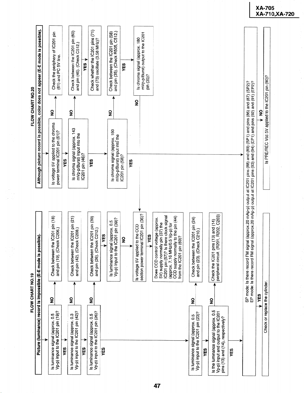
I
FLOW CHART NO.20
Although picture record is possible, color does not appear (E-E mode is possible).
I
4
(61) and PC 5V line.
, Check the periphery of IC201 pin
NO
Is voltage 5V applied to the chroma
power terminal IC2Ol pin (61)?
YES
Check between the IC201 pin (60)
Is chroma signal (approx. 143
.No
mVp-p/Burst) input into the
IC201 pin (46)?
Check whether the IC201 pins (71)
YES
and (73) oscillate (3.58 MHz)?
Check between the IC201 pin (58)
NO
Is chroma signal (approx. 180
and pin (35). (Check R505, C512.)
)
mVp-p/Burst) input into the
IC201 pin (58)?
b
YES
Is chroma signal (approx. 180
NO
mVp-p/Burst) output to the IC201
pin (35)?
I
NO
Is PRE/REC Vcc 5V applied to the IC201 pin (go)?
I
1
FLOW CHART NO.19
Picture (luminance) record is impossible (E-E mode is possible).
I
t
4
) Check between the IC201 pin (18)
Is luminance signal (approx. 0.5 NO
,
and pin (19). (Check C206.)
Vp-p) input to the IC201 pin (19)?
& YES
Check between the IC201 pin (21)
and pin (42). (Check C208.)
Check between the IC201 pin (39)
l
NO
YES 4
IS luminance signal (approx. 0.3
Vp-p) input to the IC201 pin (42)?
NO
YES
Is luminance signal (approx. 0.5
and pin (26). (Check C212.)
’
Vp-p) input to the IC201 pin (26)?
r
YES
Is luminance signal (approx. 0.5
Vp-p) input to the IC201 pin (39)v
Is voltage 5V applied to the CCD
Check between the IC201 pin (24)
Is luminance signal (approx. 0.5
and pin (23). (Check C210.)
I
Vp-p) input to the IC201 pin (23)?
peripheral circuit. (R201, R202, C203)
+ Check the IC201 pins (13) and (14)
YES
EP mode: Is there record FM signal (approx.20 mAp-p) output at IC201 pins (93) and (94) (EPI) and pins (92) and (91) (EP2)?
No
YES +
Is the luminance signal (approx. 0.5
Vp-p) input and output to the IC201
pins (13) and (14), respectively?
YES
SP mode: Is there record FM signal (approx.20 mAp-p) output at IC201 pins (88) and (89) (SPI) and pins (86) and (87) (SP2)?
Check or replace the cylinder.
Does CCD control voltage (approx.
IC201 pin (57)? Is there clock signal
5V) supply normally pin (37) the
(approx. 7.16 MHz/O.5 Vp-p) for
CCD supply normally to the pin (44)
section power terminal IC201 pin (36)? -
I
from the IC201 pin (69)?
Page 48

t
I
4
FLOW CHART NO.22
(Although picture is played back, color does not appear (E-E mode is possible). 1
Check the periphery of IC201 pin
l (61) and PC 5V line.
No
Check between the IC201 pin (60)
)
No
and pin (46). (Check C512.)
Check between the IC201 pin (58)
and pin (35)..rk R505, C515.) 1
/f!!%-~+i
Is chroma signal (approx. 508
mVp-p/Burst) output to the IC201
I I
v
YES 4
Is voltage 5V applied to the chroma
power terminal IC201 pin (61)?
Is chroma signal (approx. 403
r
I
mVp-p/Burst) input into the
IC201 pin (46)?
YES
Is chroma signal (approx. 508
mVp-p/Burst) input into the
IC201 pin (58)?
I I
YES
I
Is chroma signal (approx. 286
mVp-p/Burst) input into the
ic2bi pin (54)?-
Replace IC201.
YES 4
Does voltage 5V supply at CCD section power terminal IC201 pin (36)?
FLOW CHART NO.21
Playback picture does not appear (E-E mode is possible).
Is there control voltage approx. 5V supply normally at pin (37) from the IC201 pin (57)?
Is there CCD clock signal (approx. 7.16 MHz/O.5 Vp-p) supply at pin (44) from the IC201 pin (69)?
NO
Check V-H.SW.P. line.
Is luminance signal (approx. 0.4
Check the periphery of IC201 pins
b Check between the IC201 pin (79)
, NO
YES
Is FM signal (approx. 0.4 Vp-p)
input to the IC201 pin (78)?
Is the luminance signal (approx. 0.25 NO
Vp-p) input and output to the IC201 pins
I
(13), (14) and (16) respectively?
and pin (19). (Check C206.)
Check between the IC201 pin (21)
+ Check between the IC201 pin (18)
NO
YES 4
Is luminance signal (approx. 0.5
Vp-p) input to the IC201 pin (19)?
+
NO
YES 4
Is luminance signal (approx. 0.5
I
Vp-p) input to the IC201 pin (42)? and pin (42). (Check C208.)
I
Check between the IC201 pin (39)
YES
Is luminance signal (approx. 0.5 NO
Vp-p) input to the IC201 pin (26)?
YES
Is luminance signal (approx. 0.5
Vp-p) input to the IC201 pin (39)?
I
YES &
Replace IC201.
Is luminance signal (approx. 0.5
Vp-p) input to the IC201 pin (23)? No )
I
Page 49

t YES
xx
DD
44
&O
X
D
,v O1
I
I
$ NO
+ YES
+ NO
Replace IC651.
Check BIAS CTL (L) line.
Is the IC651 pin (33) in BIAS CTL (L) state?
v
_ Check the R353 (record current setting resistor) of IC651 pin
NO
(27).
Is there record FM signal output at IC651 pins
4 YES
Check the AA-MZ connector.
(26) and to (22) (ch-l)/pins (26) and (25) (ch-2)?
I
.’
YES
I
17
., < ._,
Is there 600 mVp-p record FM signal (L-ch) output
at IC651 pin (29) monitor terminal?
1 Hi-Fi sound cannot be recorded (E-E mode is normal). 1
Replace IC651.
FLOW CHART NO.25
Hi-Fi sound cannot be played back (E-E mode is normal).
Is there A-H.SW.P input at IC651 pin (35)?
Is there playback envelope signal output at IC651
Check the A-H.SW.P. line from the IC651
4 YES
pins (19) and (18)? (300 mVp-p)
pin (35) to the IC701 pin (26).
c
I
Replace IC651.
I
FLOW CHART NO.26
I Recording in linear audio is impossible (Hi-Fi E-E mode is normal). 1
Check the line between the IC651 pin (53) and
)
NO
Is there audio signal input at IC201 pin (8)?
IC201 pin (8).
4 YES
Check the periphery of IC201 pin (99).
Is the IC201 pin (99) in “L” level?
NO
4 YES
Check the bias oscillation circuit (T601, Q602,
Q603 and Q604).
4 YES
4 YES
Check the AA-MZ harness and A/C head.
Is there audio signal on which bias signal is
superposed output at IC201 pin (6)?
A
No Hi-Fi E-E sound heard.
FLOW CHART NO.23 Hi-Fi TROUBLESHOOTING FLOW CHART NO.24
terminal and
h audio input
NO between the
input at pin (Gl)(L-CH)
(49)(R) and (63)(L) of
and (52) (R-CH)/front
Check line
decoder circuit and audio signal input at pins
the Hi-Fi circuit.
*
signal input to pins NO between MTS
(G)(L-CH) and (44)
(R-CH) of IC651?
Hi-Fi circiut.
>
1 YES
IC651?
YES
Check IC651 and IC701, and
all the way to them.
NO
I
(31) and (32) of IC651?
Are there serial data and
serial clock signals at pins
Check between pin (8) of
H
Does “H” level supply at pin NO
1
IC651 and all the way up
to pin (21) of IC701.
H
(8) of IC651?
1 1 I
YES
Replace IC651.
t NO
t
a
co
Line coupling: Is there audio signal output at pins (58) and (56) of IC651?
RF coupling : Is there audio signal output at pin (57) of IC651?
1 YES
output terminal.
Line coupling: Check line ranging from pins (58) and (56) of IC651 to the audio
pin (2) of tuner (TUl 01).
RF coupling : Check line ranging from pin (57) of IC651 to the audio input terminal
I
t
Check lines
I
Line Audio signal input.
I
I
Is there rear audio signal
I
I
I
+
4
Audio signal input from tuner.
Is there audio
Page 50

XX
DD
FLOW CHART NO.27
4 YES
Are MH-AA harness and playback AMP. peripheral parts normal?
4 YES
Is the AC head surface clean?
I
YES
Is AC head height adjusted properly?
NO
4 YES
Replace the AC head.
Readjust the A/C head height.
Is pin (99) of IC201 in “L” level?
4 NO
YES
Check the AUDIO MUTE (H) line from pin
v
(99) of IC201 pin (22) of to IC701.
4 YES
Replace IC201.
I
I
Does IC601 operate normally?
I
NO
I I
t-i
I No record.
c
Is there a signal at pin (4) of
IC201?
FLOW CHART NO.28 LINEAR SOUND RECORDING MODE TROUBLESHOOTING
I
I
Check AT 12V line.
w
Is pin (2) of T601 in “H” level?
1 I ,
IYES
NO Check T601, Q602, Q603, Q604
Is there a signal (Bias) at pin (6) of
and their peripheral parts.
T601?
IYES
NO Check MH-AA harness and A/C
_ )
Is there a signal (Bias+Audio sig.)
1
head.
I I
at T601?
1
Linear audio playback is impossible. (Hi-Fi E-E mode is normal).
Is it possible to confirm the audio signal (PB EQ)
on pin (100) of IC201?
Is there audio signal output at pin (11) of IC201?
Check the line between pin (11) of IC201 and
pin (54) of IC651 .
Page 51

xx
DD
44
A0
“0 O1
x
D
4
N
0
I
No E-E signal
b and circuits around the audio output
NO Check parts around the audio input jack,
I
FLOW CHART NO.29 LINEAR SOUND E-E MODE TROUBLESHOOTING
Is there a signal at pins (8)
and (9) of IC201?
circuit in TUl 01.
1 I 1
1 YES
I
Check PC 5V line.
Is the supply voltage of 5V NO
H
J I
1 YES
feed to pin (96) of IC201?
I I
,
1 YES
Replace IC201.
v
1 NO
YES
IC201?
Is there ‘IL” level at pin (99) of IC201 I?
Check A-MUTE (H) line.
(57) of IC701.
) IC201 and all the way thru to pins (56) and
1 YES
(62) of IC201?
Are there the serial data and NO Check between pins (63) and (62) of
clock signal at pins (63) and
Is there a signal at pin (11) of NO
I
,
1
Check between pin (11) of IC201 and all the way up to audio output jack
and that between pin (2) of TUI 01.
peripheral circuits.
I
) Check IC6201 and its
, (Only for XA-710) 1
\r YES
Is there a signal at pin (7) of NO
IC6201?
w YES
and that between pin (2) of TUlOl (Tuner).
Check between pin (7) of IC6201 and all the way up to audio jack
Page 52

I
I
No playback.
NO
I
FLOW CHART NO.30 LINEAR SOUND PLAYBACK MODE TROUBLESHOOTING
Is there a signal at pin (100) of IC201?
v
YES
Are the MH-AA harness and the PB
AMP’s peripheral parts normal?
Replace defective parts. wNo
1 YES
Clean A/C head.
c
1
Replace IC201.
Is azimuth height of the A/C head
properly adjusted?
Readjust azimuth height. *No
YES
Replace A/C head.
* Check AUDIO MUTE (H) line.
Is there “L” level at pin (99) of IC201? No
NO
IYES
*
IVES
Is there a signal at pin (11) of IC201?
1
Check line between pin (11) of IC201 and the audio output jack, and that between pin (2) of
1 TU1O1, ,
I
peripheral circuits.
) Check lC6201 and its
(Only for XA-710)
I
IYES
Is there a signal at pin (7) of NO
IC6201?
ti YES
and between pin (2) of TUIOI (Tuner).
’ Check between pin (7) of IC6201 and audio output jack,
Page 53

Page 54

Page 55

Page 56

Page 57

Page 58

Page 59

Page 60
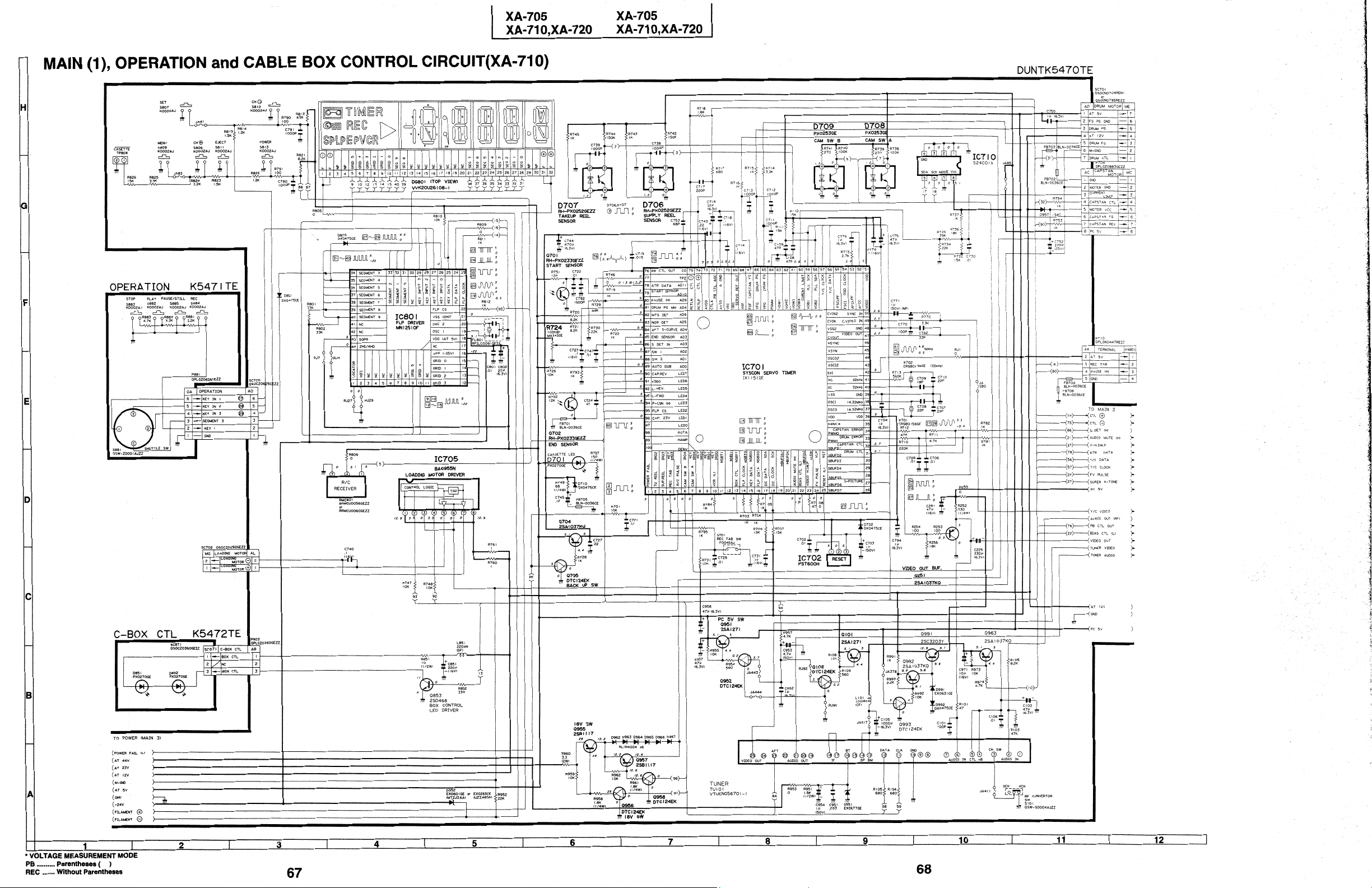
Page 61

Page 62

Page 63

Page 64

Page 65

Page 66

Page 67

Page 68

Page 69

Part No.
* Description
Ref. No.
Part No.
*
Description Code
DG801
D202
D701
D702
D706
D707
D708
0709
D710
D801
0805
0811
A D902
A 0903
A D904
A D905
A D906
A D907
A 0908
A D909
A 0911
A D912
A D914
A D915
0917
a D918
A D921
A D922
A D923
A 0925
D951
0952
D957
D962
D963
0964
0965
D966
D967
D991
0992
A IC901
Q701
Q702
X501
x701
X702
DUNTK5470TEVJ (XA-705)
DUNTK5470TEVK (XA-710)
DUNTK5470TEVL (XA-720)
MAIN UNIT (Continued)
DIODES
VVK20U26108-1 V Display
RH-DX0475CEZZ V Diode
RH-PX0270GEZZ V LED
RH-DX0475CEZZ V Diode
RH-PX0252GEZZ V GPI S563
RH-PX0252GEZZ V GPI S563
RH-PX0253GEZZ V GPI S94
RH-PX0253GEZZ V GPI S94
RH-DX0475CEZZ V Diode
RH-DX0475CEZZ V Diode
RH-DX0475CEZZ
RH-DX0475CEZZ V Diode (XA-705)
VHDlOELS4//-1 V Diode
RH-DX0475CEZZ V Diode
RH-DX0475CEZZ V Diode
VHDI OELS4//-1 V Diode
VHDI 5DFl FC/l E V Diode
VHDI OELS4//-1 V Diode
VHDI S40////-1
VHDI OELS4//-1 V Diode
RH-EX0601GEZZ V Zener Diode, 3.6V
RH-DX0475CEZZ V Diode
RH-EXO613GEZZ V Zener Diode
RH-DX0475CEZZ V Diode
RH-EXO619GEZZ V Zener Diode
VHDI OELS4//-1
VHDRLI N4004-1
VHDRLI N4004-1
VHDRLI N4004-1
VHDRLI N4004-1
RH-EX0677GEZZ V Zener Diode, 33V
RH-EX0601GEZZ
VHDI S40////-1
VHDRLI N4004-1 V Diode
VHDRLI N4004-1 V Diode
VHDRLI N4004-1 V Diode
VHDRLI N4004-1 V Diode
VHDRLI N4004-I V Diode
VHDRLI N4004-1 V Diode
RH-EX0631GEZZ V Zener Diode
RH-DX0475CEZZ V Diode
RH-FX0034CEZZ V Photo Coupler
RH-PX0233GEZZ V START Sensor
RH-PX0233GEZZ V END Sensor
PACKAGED CIRCUITS
RCRSB0204GEZZ V Crystal, 3.58MHz
RCRSBO156GEZZ V Crystal
RCRSBOI 38GENl V Crystal, 32kHz
V Diode (XA-71 O/720)
V Diode
V Diode
V Diode
V Diode
V Diode
V Diode
V Zener Diode, 3.6V
V Diode
AW
AB
AC
AB
AF
AF
AF
AF
AB
AB
AB
AB
AD
AB
AB
AD
AD
AD
AF
AD
AA
AB
AA
AB
AA
AD
AD
AD
AD
AD
AB
AA
AF
AD
AD
AD
AD
AD
AD
AA
AB
AE
AD
AD
AG
AF
AD
FILTER
FL801 RFiLC0091 GEZZ V Filter, 4MHz
AD
COILS
LIOI
L201
L202
L301 VP-ZKI 01 KOOOO V Peaking IOOuH AB
L351 VP-ZKI 01 KOOOO V Peaking IOOpH (XA-720) AB
L501
L602 VP-DF221 KOOOO V Peaking 220f~H AB
L851 VP-DF221 KOOOO V Peaking 220uH AB
L901 RCiLF0002AJZZ V Coil
L902 RCiLP0161 CEZZ V Coil AD
L903 RCiLP0161 CEZZ V Coil
VP-CFI 01 KOOOO
VP-XF820KOOOO V Peaking 82uH
VP-XFI 01 KOOOO
VP-XFI 20KOOOO
V Peaking IOOpH AB
AB
V Peaking IOOpH AB
V Peaking 12f~H AB
(XA-71 O/720)
AK
AD
TRANSFORMERS
T601
T901
RTRNH0086GEZZ V Osc. Transformer
RTRNZ0047AJZZ V Pluse Transformer
AD
AV
CONTROLS
RI41 RVR-M4340GEZZ V 47k (B) S-IF Adj. (XA-720) AB
RI62 RVR-M4340GEZZ
RI 63 RVR-M4337GEZZ
RI64 RVR-M4340GEZZ V 47k (B) Separation (1) Adj. AB
RI65 RVR-M4331GEZZ V 4.7k (B) Separation (2) Adj. AC
R724 RVR-M4343GEZZ V IOOk (B) (XA-720)
V 22k (B) ST VCO Adj. AB
(XA-720)
V 22k (B) Filter Adj. (XA-720) AB
(XA-720)
(XA-720)
AB
CAPACITORS
Cl01 VCKYD41 HBIOIK V 100~ 50V Ceramic
Cl03 VCEA9AOJW476M V 47 6.3V Electrolytic AB
Cl05 VCEAGAOJW108M V 1000 6.3V Electrolytic AC
Cl06 VCKYCYlHF1032 V 0.01
Cl08 VCCCCYlHH470J V 47p 50V Ceramic AA
Cl09 VCCCCYlHH470J V 47p 50V Ceramic AA
Cl61 VCEASMlCW106M V IO
Cl62 VCEASAlHW475M V 4.7
Cl63 VCKYCYlEB123K V 0.012 25V Ceramic AA
Cl64 VCKYCYI HB562K V 5600~ 50V Ceramic
Cl65 VCEASMlHW474M V 0.47 50V Electrolytic AB
Cl66 VCEASAlHW475M V 4.7
Cl67 VCKYCYlCB473K V 0.047 16V Ceramic AA
Cl68 VCEASAI HW475M V 4.7 50V Electrolytic AB
Cl69 VCEASMI HW475M V 4.7
50V Ceramic AA
16V Electrolytic AB
(XA-720)
50V Electrolytic AB
(XA-720)
(XA-720)
(XA-720)
(XA-720)
50V Electrolytic AB
(XA-720)
(XA-720)
(XA-720)
50V Electrolytic AB
(XA-720)
AA
AA
85
Page 70

Ref. No. Part No.
*
Description
Code
Ref. No.
Part No. *
Description Code
DUNTK5470TEVJ (XA-705)
DUNTK5470TEVK (XA-710)
DUNTK5470TEVL (XA-720)
MAIN UNIT (Continued)
Cl70 VCEASMI HW335M V 3.3
Cl71
Cl72 VCEASMlCWl06M V 10 16V Electrolytic AB
Cl73 VCEASMI HW475M V 4.7 50V Electrolytic AB
Cl74 VCKYCYI HB272K V 2700~ 50V Ceramic
Cl75 VCEASAOJW476M V 47
Cl76 VCESEAlHW474M V 0.47 50V Elect. (N.P) AB
Cl77 VCKYCYlCFl04Z V 0.1
Cl78 VCKYCYlCFl04Z V 0.1
Cl79 VCEASMlCW476M V 47 16V Electrolytic AB
c201
C202 VCKYCYlCF224Z V 0.22
C203 VCCCCYI HHl51 J V 150~ 50V Ceramic
C204 VCKYCYlCFl04Z V 0.1
C205 VCCCCYlHH390J V 39p
C206 VCKYCYlCFl04Z V 0.1 16V Ceramic AA
C207 VCKYCYlCFl04Z V 0.1 16V Ceramic AA
C208 VCEASMlCWl06M V 10
C209 VCKYCYlCFl04Z V 0.1 16V Ceramic AA
C210 VCKYCYlCFl04Z V 0.1
c211
C212 VCEASMlCWl06M V 10
C213 VCEA9Ml HW225M V 2.2 50V Electrolytic AB
C214 VCKYCYOJFl05Z V 1 6.3V Ceramic AB
C215 VCKYCYOJFl05Z V 1 6.3V Ceramic AB
C216 VCKYCYOJFl05Z V 1 6.3V Ceramic AB
C217 VCEA9MOJW476M V 47 6.3V Electrolytic AB
C218 VCKYCYI HFl03Z V 0.01 50V Ceramic AA
C219 VCKYCYlCFl04Z V 0.1
C220 VCKYCYlCFl04Z V 0.1
C221 VCEASMlCWl06M V 10 16V Electrolytic AB
C222 VCEA9MOJW476M V 47 6.3V Electrolytic AB
C223 VCKYCYlCF474Z V 0.47 16V Ceramic AB
C225 VCEAGAOJW337M V 330 6.3V Electrolytic AB
C251 VCEASMlCW476M V 47 16V Electrolytic AB
C301 VCEA9MOJW476M V 47
C302 VCKYCYI HFl03Z V 0.01 50V Ceramic AA
C303 VCKYCYI HBIOZK V IOOOp 50V Ceramic
C304 VCKYCYI HBIOZK V IOOOp 50V Ceramic
C305 VCKYCYI HBIOZK V IOOOp 50V Ceramic
C306 VCKYCYI HBIOZK V IOOOp 50V Ceramic
VCEASMlHWl05M V 1
VCEA9MOJWl07M V 100 6.3V Electrolytic AB
VCEASMI HW335M V 3.3
5OV Electrolytic AB
(XA-720)
50V Electrolytic AB
(XA-720)
(XA-720)
(XA-720)
AA
(XA-720)
6.3V Electrolytic AB
(XA-720)
(XA-720)
16V Ceramic AA
(XA-720)
16V Ceramic AA
(XA-720)
(XA-720)
16V Ceramic AA
AA
16V Ceramic AA
50V Ceramic AA
16V Electrolytic AB
16V Ceramic AA
50V Electrolytic AB
16V Electrolytic AB
(XA-71 O/720)
16V Ceramic AA
16V Ceramic AA
6.3V Electrolytic AB
AA
AA
AA
AA
c307
C308
c309
c310
c311
C312
c319
C320
c351
C352 .
c353
c354
c355
C356
c357
c501
C502
c503
c504
c505
C506
c507
C508
c509
c511
C512
c513
c514
c515
c517
C518
C521
C601
C602
C603
C604
C605
C606
C607
C608
C609
C610
C611
C612
C613
C616
C617
VCKYCYI HBIOZK V IOOOp 50V Ceramic
VCKYCYI HBIOZK V IOOOp 50V Ceramic
VCKYCYI HBIOZK V IOOOp 50V Ceramic
VCKYCYI HBIOZK V IOOOp 50V Ceramic
VCKYCYI EBI 03K V 0.01
VCKYCYI HFI 032 V 0.01
VCCCCYlHHl50J V 15p
VCCCCYlHHl50J V 15p
VCEA9MOJW476M V 47
VCKYCYlCFl04Z V 0.1
VCKYCYlHB332K V 3300~ 50V Ceramic
VCKYCYI HFI 032
VCKYCYOJFl05Z V 1 6.3V Ceramic
VCCCCYI HHIOI J V 100~ 50V Ceramic
VCCCPAI HH560J V 56p
VCEASMOJWI 07M V 100
VCKYCYI HFl03Z V 0.01
VCKYCYlHB472K V 4700~ 50V Ceramic
VCEASMI HW225M V 2.2 50V Electrolytic
VCKYCYlHF223Z V 0.022 50V Ceramic
VCEASMI HW474M V 0.47
VCKYCYlCFl04Z V 0.1 16V Ceramic
VCEASMI HW475M V 4.7
VCKYCYI HFI 032
VCCCCYI HHSROC V 5.0~
VCKYCYI HFl03Z V 0.01
VCKYCYI HFI 032
VCKYCYI HFI 032
VCKYCYlHB33lK V 330~ 50V Ceramic
VCEASMI HW335M V 3.3 50V Electrolytic
VCKYCYlHF333Z V 0.033 50V Ceramic
VCCCCYIHHSROC V 5p 50V Ceramic
VCEASMOJWI 07M V 100
VCKYCYI EBl03K V 0.01
VCEA9AOJW226M V 22 6.3V Electrolytic
VCKYCYlHB82lK V 820~ 50V Ceramic
VCEASMlCWl06M V 10
VCEASMI HW475M V 4.7
VCEASMI HW475M V 4.7
VCEA9MOJW226M V 22
VCEASMI HW475M V 4.7
VCKYCYlCFl04Z V 0.1
VCKYCYlCFl04Z V 0.1
VCKYCYlCFl04Z V 0.1
VCKYCYI EBl83K V 0.018 25V Ceramic
VCKYCYIHBZZZK V 2200~ 50V Ceramic
VCEASMlCW476M V 47 16V Electrolytic
V 0.01 50V Ceramic
V 0.01 50V Ceramic
V 0.01 50V Ceramic
V 0.01 50V Ceramic
25V Ceramic
50V Ceramic
50V Ceramic
50V Ceramic
6.3V Electrolytic
(XA-720)
16V Ceramic
(XA-720)
(XA-720)
(XA-720)
(XA-720)
(XA-720)
50V Ceramic
(XA-720)
6.3V Electrolytic
50V Ceramic
50V Electrolytic
50V Electrolytic
50V Ceramic
50V Ceramic
6.3V Electrolytic
25V Ceramic
16V Electrolytic
50V Electrolytic
50V Electrolytic
6.3V Electrolytic
50V Electrolytic
16V Ceramic
(XA-705/10)
16V Ceramic
16V Ceramic
(XA-710)
(XA-705/10)
AA
AA
AA
AA
AA
AA
AA
AA
AB
AA
AA
AA
AB
AA
AA
AB
AA
AA
AB
AB
AB
AA
AB
AA
AA
AA
AA
AA
AA
AB
AA
AA
AB
AA
AB
AA
AB
AB
AB
AB
AB
AA
AA
AA
AA
AA
AB
86
Page 71

XA-705
XA-71 O,XA-720
Part No.
* Description
DUNTK5470TEVJ (XA-705)
DUNTK5470TEVK (XA-710)
DUNTK5470TEVL (XA-720)
MAIN UNIT (Continued)
C618
C619
C620
C621
C622
C630
C651
C652
C653
C654
C655
C656
C657
C658
C659
C664
VCKYCYI EBI 03K V 0.01
VCKYCYI EBI 03K V 0.01
VCEASMI CWl06M V 10
VCQPYA2AA562J V 5600~ IOOV Mylar
VCKYCYlHB222K V 2200~ 50V Ceramic
VCKYCYOJFl052 V 1
VCKYCYI CF224Z V 0.22
(XA-720)
VCEA9MOJW226M V 22
(XA-720)
VCEASMI HW475M V 4.7
(XA-720)
VCKYCYI EB103K V 0.01
(XA-720)
VCEA9MOJW226M V 22
(XA-720)
VCKYCYI HB472K V 4700~ 50V Ceramic
(XA-720)
VCKYCYlHB332K V 3300~ 50V Ceramic
(XA-720)
VCEASMlCWl06M V IO
(XA-720)
VCEASMlCWl06M V 10
(XA-720)
VCKYCYlCF224Z V 0.22
(XA-720)
VCEA9MOJW226M V 22
(XA-720)
VCEASMI HW475M V 4.7
(XA-720)
VCKYCYI EBI 03K V 0.01
(XA-720)
C665
C666
C667
C671
C672
C673
C676
C677
VCEASMOJW226M V 22
(XA-720)
VCKYCYlHB472K V 4700~ 50V Ceramic
(XA-720)
VCKYCYlHB332K V 3300~ 50V Ceramic
(XA-720)
VCEA9MOJW476M V 47 6.3V Electrolytic
(XA-720)
VCEASMlCWl06M V IO 16V Electrolytic
(XA-720)
VCKYCYlCF104Z V 0.1 16V Ceramic
(XA-720)
VCEASMlCWl06M V IO
(XA-720)
VCKYCYOJFl05Z V 1
(XA-720)
C678
C679
VCKYCYI CF224Z V 0.22 16V Ceramic
(XA-720)
VCKYCYI CF224Z V 0.22 16V Ceramic
(XA-720)
25V Ceramic
25V Ceramic
16V Electrolytic
6.3V Ceramic
16V Ceramic
6.3V Electrolytic
50V Electrolytic
25V Ceramic
6.3V Electrolytic
16V Electrolytic
16V Electrolytic
16V Ceramic
6.3V Electrolytic
50V Electrolytic
25V Ceramic
6.3V Electrolytic
16V Electrolytic
6.3V Ceramic
AA
AA
AB
AC
AA
AB
AA
AB
AB
AA
AB
AA
AA
AB
AB
AA
AB
AB
AA
AB
AA
AA
AB
AB
AA
AB
AB
AA
AA
Ref. No.
C680
C699
c701
C702
c703
c704
c705
C706
c707
C708
c709
c710
c711
C712
c713
c714
c715
c717
C718
c719
C722
C723
C724
C726
C727
c729
c730
c731
C738
c739
c740
c743
c744
c745
c747
c750
C752
c753
c770
c771
c774
c775
C776
C782
c790
c791
c792
c793
c794
C801
C802
C851
Part No.
VCKYCYOJFI 05Z
VCEA9MOJW226M
VCKYCYI HFI 032
VCKYCYI HFl03Z
VCEASMI HWI 05M
VCKYCYOJFI 05Z
VCKYCYI EBl03K
VCKYCYI EBI 03K
VCCCCYI HH220J
VCCCCYI HH220J
VCCCCYI HHI 80J
VCCCCYI HH220J
VCKYCYI HBI 02K
VCKYCYlHBl02K
VCKYCYI HBI 02K
VCKYCY 1 CFI 042
VCEA9MOJW226M
VCKYCYI HB221 K
VCKYCYI CFI 042
VCKYCYI EBI 53K
VCKYCY 1 HFI 032
VCKYCYI CFI 042
VCKYCYlHFl03Z
VCKYCY 1 HFI 032
VCKYCYI CF224Z
VCKYCYI HFl03Z
VCKYCYI HFI 032
VCKYCYI CFI 042
VCKYCYI HBI 02K
VCKYCYI HBl02K
VCKYCYI CFI 042
VCKYCYI CF224Z
VCEA2AOJW477M
RC-EZOIIIGEZZ
VCKYCYI HFI 032
VCKYCYOJFI 05Z
VCEA2Al EW337M
VCCCCY 1 HH680J
VCCCCYIHHIOIJ
VCE9EMl HWI 05M
VCKYCYI CF104Z
VCEA9MOJW476M
VCKYCYOJFlO5Z
VCCCCYI HH330J
VCKYCYI HBl02K
VCKYCYlHB102K
VCKYCYI HB102K
VCKYCYlHF1032
VCKYCYOJFI 05Z
VCKYCYI HF103Z
VCEA9MOJW226M
VCEAGAI CW227M
*
V
V
V
V
V
V
V
V
V
V
V
V
V
V
V
V
V
V
V
V
V
V
V
V
V
V
V
V
V
V
V
V
V
V
V
V
V
V
V
V
V
V
V
V
V
V
V
V
Description
1 6.3V Ceramic
(XA-720)
22 6.3V Electrolytic
(XA-720)
0.01 50V Ceramic
0.01 50V Ceramic
1 50V Electrolytic
1
6.3V Ceramic
0.01 25V Ceramic
0.01
25V Ceramic
50V Ceramic
22P
50V Ceramic
22P
50V Ceramic
18P
50V Ceramic
22P
IOOOp 50V Ceramic
IOOOp 50V Ceramic
IOOOp 50V Ceramic
0.1 16V Ceramic
22 6.3V Electrolytic
220p 5OV Ceramic
0.1 16V Ceramic
0.015 25V Ceramic
0.01 50V Ceramic
0.1 16V Ceramic
0.01
50V Ceramic
0.01
50V Ceramic
(XA-720)
0.22 16V Ceramic
0.01 50V Ceramic
0.01 50V Ceramic
0.1 16V Ceramic
IOOOp 50V Ceramic
IOOOp 50V Ceramic
0.1
16V Ceramic
0.22 16V Ceramic
470 6.3V Electrolytic
0.01 Electrolytic
0.01 50V Ceramic
1 6.3V Ceramic
330 25V Electrolytic
50V Ceramic
68P
IOOp 50V Ceramic
1
50V Elect. (N.P)
0.1 16V Ceramic
47
6.3V Electrolytic
1 6.3V Ceramic
50V Ceramic
33P
1OOOp 5OV Ceramic
IOOOp 50V Ceramic
IOOOp 50V Ceramic
0.01
5OV Ceramic
(XA-720)
1
6.3V Ceramic
0.01
50V Ceramic
22
6.3V Electrolytic
220 16V Electrolytic
(XA-71 O/720)
AB
AB
AA
AA
AB
AB
AA
AA
AA
AA
AA
AA
AA
AA
AA
AA
AB
AA
AA
AA
AA
AA
AA
AA
AA
AA
AA
AA
AA
AA
AA
AA
AB
AH
AA
AB
AD
AA
AA
AB
AA
AB
AB
AA
AA
AA
AA
AA
AB
AA
AB
AC
87
Page 72

j ~~:5%A-720
Ref. No. Part No.
*
Description Code
DUNTK5470TEVJ (XA-705)
DUNTK5470TEVK (XA-710)
DUNTK5470TEVL (XA-720)
MAIN UNIT (Continued)
A c901
A c903
A c904
A c905 RC-KZ0029CEZZ
A C906 VCKYPA2HB22lK V 220~ 500V Ceramic
A c907 VCKYCYlHB472K V 4700~ 50V Ceramic
&, C908 VCKYCYlHB22lK V 220~ 50V Ceramic AA
A c909 VCKYCYlHB332K V 3300~ 50V Ceramic
A c911 VCEAGAI JWl06M V IO 63V Electrolytic AB
A c912 VCEAGAl VW477M V 470 35V Electrolytic AD
A c913 VCEAGAI CW337M V 330 16V Electrolytic AC
A c914 VCEAGAlHW226M V 22 50V Electrolytic AB
A C916 VCEAGAOJWI 08M V 1000 6.3V Electrolytic AC
A c917 VCEAGAOJWl08M V 1000 6.3V Electrolytic AC
A C918 VCKYCYlCFl04Z V 0.1 16V Ceramic AA
A c919 VCEAGAOJWI 07M V 100 6.3V Electrolytic AB
A c921 VCKYCYOJFl05Z V 1 6.3V Ceramic AB
A c922
A c923
A c930
RC-FZ023CUMZZ V 0.01 AC250V Mylar
RC-KZOI 47GEZZ
RC-EZ0238CEZZ
VCEAGAl VW477M V 470 35V Electrolytic AD
VCKYCYI HFI 032
VCQYTAlHM333K V 0.033 50V Mylar AA
c951 VCKYCYlHF333Z V 0.033 50V Ceramic AA
C952 VCKYCYOJFl05Z V 1
C953 VCEASMlHW475M V 4.7 50V Electrolytic AB
C954 VCEASMlHWl05M V 1 50V Electrolytic AB
C957 VCEA9MOJW476M V 47
C958 VCEA9MOJW476M V 47
c971 VCEASMlCWl06M V IO
c991 VCEASMlCW476M V 47
V 3300~ ACl25V Ceramic AC
V 82 200V Electrolytic AE
v 0.01
V 0.01
500V Ceramic AC
50V Ceramic AA
6.3V Ceramic AB
6.3V Electrolytic AB
6.3V Electrolytic AB
16V Electrolytic AB
16V Electrolytic AB
(XA-720)
AF
AA
AA
AA
RESISTORS
RJI VRS-CYIJFOOOJ V 0 l/l 6W Metal Oxide AA
RJ4
RJ7 VRS-CYI JFOOOJ
RJ27 VRS-CYIJFOOOJ V 0 l/l 6W Metal Oxide AA
RJ29 VRS-CYIJFOOOJ V 0 l/l 6W Metal Oxide AA
RJ92 VRS-CYIJFOOOJ V 0
RJ94 VRS-CYIJFOOOJ V 0
RI01 VRS-CYI JF47OJ V 47 l/l 6W Metal Oxide AA
R103 VRS-CYI JF473J V 47k 1/16W Metal Oxide AA
RI 04 VRS-CYI JF681 J V 680 l/l 6W Metal Oxide AA
RI05 VRS-CYlJF68lJ
RI 06 VRD-RA2BE822J
VRS-CYIJFOOOJ V 0 l/l 6W Metal Oxide AA
V 0
V 680 Ill 6W Metal Oxide AA
V 8.2k 1/8W Carbon AA
RI07 VRS-CYlJF822J V 8.2k l/l 6W Metal Oxide AA
RI08 VRS-CYlJFl03J V IOk l/l 6W Metal Oxide AA
RI09 VRS-CYlJF56lJ
RI10 VRS-CYlJFl53J V 15k l/l 6W Metal Oxide AA
RI11 VRS-CY 1 JFI 53J V 15k 1/16W Metal Oxide AA
V 560 l/l 6W Metal Oxide AA
l/l 6W Metal Oxide AA
(XA-705/710)
l/l 6W Metal Oxide AA
l/l 6W Metal Oxide AA
(XA-705/710)
(XA-720)
Ref. No.
RI66
RI 68
RI69
RI70
RI71
RI72
RI73
RI74
RI 75
RI76
RI77 Metal Oxide
RI 79‘ VRS-CYI JF333J
RI80 VRS-CYI JFI 03J
RI81 VRS-CYI JF223J
R201
R202
R203
R207
R208
R209
R210
R211
R212
R213
R214
R216
R217
R218
R219
R220
R221
R222
R228
R229 VRS-CYI JFOOOJ
R229
R232
Part No. Description
VRS-CYIJFIOSJ
VRS-CYlJFl04J
VRS-CYI JFI 83J
VRSCYlJFl03F
VRS-CYI JFI 04J
VRS-CYI JF222J
VRS-CYI JF682J
VRS-CYI JF682J
VRS-CYI JF393J
VRS-CY 1 JF473J
VRS-CYI JF473J
VRS-CYI JF392J
VRS-CYI JF332J RI78
VRS-CYI JF682J
VRS-CYI JFl82J
VRS-CYI JF332J
VRD-RA2BElOl J
VRS-CYI JF272J
VRS-CYI JF331 J
VRS-CYI JFI 82J
VRS-CYI JF822J
VRS-CYI JF681 J
VRS-CYI JF822J
VRS-CYI JFI 04J
VRS-CYI JFI 02J
VRS-CYI JF681 J
VRS-CYI JF471 J
VRS-CYI JF561 J
VRS-CYI JF272J
VRS-CYI JFI 03J
VRD-RA2BElO2J
VRS-CYI JF75OJ
VRS-CYIJFIOIJ
VRS-CYI JFI 53J
V IM 1/16W
(XA-720)
V IOOk lll6W
(XA-720)
V 18k lll6W
(XA-720)
V IOk lll6W
(XA-720)
V IOOk lll6W
(XA-720)
V 2.2k lll6W
(XA-720)
V 6.8k lll6W
(XA-720)
V 6.8k lll6W
(XA-720)
V 39k lll6W
(XA-720)
V 47k 1/16W
(XA-720)
V 47k lll6W
(XA-720)
V 3.9k 1/16W
(XA-720)
V 3.3k lll6W
(XA-720)
V 33k lll6W
(XA-720)
V IOk lll6W
(XA-720)
V 22k lll6W
(XA-720)
V 6.8k lll6W
V 1.8k 1/16W
V 3.3k lll6W
V 100 ll8W
V 2.7k lll6W
V 330 lll6W
V 1.8k lll6W
V 8.2k 1/16W
V 680 1/16W
V 8.2k lll6W
V IOOk 1/16W
V lk lll6W
V 680 lll6W
V 470 lll6W
V 560 1/16W
V 2.7k lll6W
V IOk lll6W
V lk ll8W
V 75 lll6W
(XA-720)
vo lll6W
(XA-720)
V 100 lll6W
(XA-710)
V 15k lll6W
Metal Oxide AA
Metal Oxide AA
Metal Oxide
Metal Oxide
Metal Oxide
Metal Oxide
Metal Oxide
Metal Oxide
Metal Oxide
Metal Oxide
Metal Oxide AA
Metal Oxide AA
Metal Oxide
Metal Oxide
Metal Oxide AA
Metal Oxide
Metal Oxide
Metal Oxide
Carbon
Metal Oxide
Metal Oxide
Metal Oxide
Metal Oxide
Metal Oxide
Metal Oxide
Metal Oxide
Metal Oxide
Metal Oxide
Metal Oxide
Metal Oxide
Metal Oxide
Metal Oxide
Carbon
Metal Oxide
Metal Oxide AA
Metal Oxide AA
Metal Oxide AA
AA
AA
AA
AA
AA
AA
AA
AA
AB
88
Page 73

XA-705
XA-71 O,XA-720
Ref. No. Part No.
*
Description Code
DUNTK5470TEVJ (XA-705)
DUNTK5470TEVK (XA-710)
DUNTK5470TEVL (XA-720)
MAIN UNIT (Continued)
R233
R252
R253
R254
R255
R256
R301
R304
R351
R352
VRS-CYlJF153J
VRD-RA2EE331 J
VRS-CYI JFI 01 J
VRS-CYI JFI 01 J
VRS-CYI JFOOOJ
VRS-CYI JFI 83J
VRS-CY 1 JF473J
VRS-CY 1 JFOOOJ
VRS-CYI JF473J
VRS-CYI JF473J AA
VRS-CYI JF272J AA
R353
R354 VRS-CYI JF471 J AA
R501
VRS-CYI JFI 02J
R502
VRS-CY 1 JF273J
R601
VRS-CYI JF822J
VRS-CYI JF274J
R602
VRS-CYI JF221 J
R603
VRS-CYI JF473J
R604
R605
R606
R607
R608
R609
R611
R612
R612
R615
R616
R617
R618
R619
R620
R621
VRS-CYI JFI 53J
VRS-CY 1 JF273J
VRS-CYI JF561 J
VRS-CYI JF472J
VRS-CYI JF333J
VRS-CYI JFI 83J
VRS-CYI JF153J
VRS-CY 1 JF393J
VRS-CYI JFI 23J
VRS-CY 1 JF683J
VRS-CYI JF393J
VRS-CYI JF123J
VRS-CY 1 JF222J AA
VRS-CYI JFI 03J
VRS-CYI JFI 034
VRS-CY 1 JF563J
VRS-CYI JF47OJ
VRS-CYI JFI 53J
VRD-RA2EE4R7J
V 15k l/l 6W Metal Oxide
V 330 1/4W Carbon
V 100 l/l 6W Metal Oxide
V 100 l/l 6W Metal Oxide
v 0
V 18k l/l 6W Metal Oxide
V 47k l/l 6W Metal Oxide
v 0
V 47k l/l 6W Metal Oxide
V 47k l/l 6W Metal Oxide
V 2.7k l/l 6W Metal Oxide
V 470 l/l 6W Metal Oxide
V 1 k l/l 6W Metal Oxide
V 27k l/l 6W Metal Oxide
V 8.2k l/l 6W Metal Oxide
V 270k l/l 6W Metal Oxide
V 220 l/l 6W Metal Oxide
V 47k l/l 6W Metal Oxide
V 15k l/l 6W Metal Oxide
V 27k l/l 6W Metal Oxide
V 560 l/l 6W Metal Oxide
V 4.7k l/l 6W Metal Oxide
V 33k l/l 6W Metal Oxide
V 18k l/l 6W Metal Oxide
V 15k l/l 6W Metal Oxide
V 39k l/l 6W Metal Oxide
V 12k l/l 6W Metal Oxide
V 68k l/l 6W Metal Oxide
V 39k l/l 6W Metal Oxide
V 12k l/l 6W Metal Oxide
V 2.2k l/l 6W Metal Oxide
V 1 Ok l/l 6W Metal Oxide
V 1 Ok l/l 6W Metal Oxide
V 56k l/l 6W Metal Oxide
V 47 l/l 6W Metal Oxide
V 15k 1/16W MetalOxide
V 4.7 1/4W Carbon
l/l 6W Metal Oxide
l/l 6W Metal Oxide
(XA-720)
(XA-720)
(XA-720)
(XA-720)
(XA-705/710)
(XA-705/710)
(XA-720)
(XA-705/7 IO)
(XA-705/710)
(XA-720)
(XA-710)
(XA-710)
(XA-705/710)
(XA-705/710)
(XA-720)
AA
AA
AA
AA
AA
AA
AA
AA
AA
AA
AA
AA
AA
AA
AA
AA
AA
AA
AA
AA
AA
AA
AA
AA
AA
AA
AA
AA
AA
AA
AA
AA
AA
Ref. No. Part No. Description Code
R622
R623
R624
R625
R626
R627 VRS-CYI JFOOOJ
R628 VRS-CYI JFOOOJ
R628 VRS-CYI JF331 J
R629 VRD-RA2BE331 J
R651 VRS-CYI JF273J
R652
R653 VRS-CY I JF473J
R654
R655
R657
R658 VRS-CYI JF682J
VRS-CYI JFI 02J
VRD-RA2BE393J
VRD-RA2BE224J
VRS-CY 1 JFOOOJ
VRS-CYI JFOOOJ
VRS-CYI JF472J
VRS-CY 1 JF822J
VRS-CY 1 JF473J
VRS-CYI JF822J R656
VRS-CYI JF821 J
R661
R662
R663 VRD-RA2BE473J
R664 VRS-CY 1 JF822J
R665
R666
R667 VRS-CYI JF821 J
R668 VRS-CYI JF682J
R671
VRD-RA2BE273J
VRS-CYI JF472J
VRD-RA2BE473J
VRS-CYI JF822J
VRS-CYI JF123J
R672
R675
R676 VRS-CYI JFOOOJ
R677
R701
VRS-CYI JF472J
VRS-CYlJF103J
VRS-CYI JFOOOJ
VRS-CYlJF103J
V 1 k l/l 6W Metal Oxide
V 39k 1/8W Carbon
V 220k 1/8W Carbon
v 0 l/l 6W Metal Oxide
vo l/l 6W Metal Oxide
(XA-705/710)
v 0 l/l 6W Metal Oxide
(XA-705/710)
v 0 l/l 6W Metal Oxide
(XA-705/710)
V 330 l/l 6W Metal Oxide
(XA-720)
V 330 ll8W
(XA-720)
V 27k l/l 6W Metal Oxide
(XA-720)
V 4.7k l/l 6W Metal Oxide
(XA-720)
V 47k l/l 6W Metal Oxide
(XA-720)
V 8.2k l/l 6W Metal Oxide
(XA-720)
V 47k l/l 6W Metal Oxide
(XA-720)
V 8.2k l/l 6W Metal Oxide
(XA-720)
V 820 l/l 6W Metal Oxide
(XA-720)
V 6.8k l/l 6W Metal Oxide
(XA-720)
V 27k 1/8W
(XA-720)
V 4.7k l/l 6W Metal Oxide
(XA-720)
V 47k 1/8W Carbon
(XA-720)
V 8.2k l/l 6W Metal Oxide
(XA-720)
V 47k 1/8W Carbon
(XA-720)
V 8.2k l/l 6W Metal Oxide
(XA-720)
V 820 l/l 6W Metal Oxide
(XA-720)
V 6.8k l/l 6W Metal Oxide
(XA-720)
V 12k l/l 6W Metal Oxide
(XA-720)
V 4.7k l/l 6W Metal Oxide
(XA-720)
V 1 Ok l/l 6W Metal Oxide
(XA-720)
vo
(XA-720)
vo
(XA-720)
V 1 Ok l/l 6W Metal Oxide AA
Carbon AA
Carbon
l/l 6W Metal Oxide
l/l 6W Metal Oxide
AA
AA
AA
AA
AA
AA
AA
AA
AA
AA
AA
AA
AA
AA
AA
AA
AA
AA
AA
AA
AA
AA
AA
AA
AA
AA
AA
AA
AA
89
Page 74

j
EZ,&
I
Ref. No. Part No.
* Description Code
DUNTK5470TEVJ (XA-705)
DUNTK5470TEVK (XA-710)
. DUNTK547OTEVL (XA-720)
MAIN UNIT (Continued)
R703 VRD-RA2BElO2J V lk 1/8W Carbon
R704 VRD-RA2BElO2J V lk ll8W Carbon
R705 VRD-RA2BElO2J V 1 k 1/8W Carbon
R706 VRS-CYI JFI 53J
R707 VRS-CYlJFl53J
R708 VRS-CY 1 JF471 J
R709 VRS-CYI JFI 02J
R710 VRS-CYI JF224J
R711 VRS-CYI JF472J
R712 VRS-CYI JF473J
R713 VRS-CYI JF564J
R714 VRD-RA2BE332J V 3.3k 1/8W
R715 VRD-RA2BElO2J
R716 VRS-CYI JFI 02J
R717 VRD-RA2BE681 J
R718 VRS-CYI JFI 82J
R719 VRD-RA2BElO2J
R720 VRD-RA2BElO3J
R720 VRD-RA2BE822J
R721 VRD-RA2BE822J
R722 VRD-RA2BElO2J
R726 VRD-RA2BElO3J
R727 VRD-RA2EEl51 J v 150 ll4W
R728 VRS-CYI JFI 02J
R729 VRD-RA2BE683J
R730 VRS-CYI JF223J
R731 VRS-CYlJFl03J
R732 VRS-CYI JFI 53J
R734 VRS-CY 1 JF223J
R735 VRS-CY 1 JF393J
R736 VRS-CYI JFl83J
R737 VRS-CYI JFI 02J
R738 VRD-RA2BElO4J
R739 VRD-RA2BE271 J
R740 VRS-CYI JFI 04J
R741 VRD-RA2BE271 J
R742 VRS-CYI JFl54J
R743 VRD-RA2BElO2J
R744 VRS-CYI JFI 54J
R745 VRD-RA2BElO2J
R746 VRS-CYIJFOOOJ V 0
R747 VRS-CYI JFI 03J
R748 VRS-CYI JFlO3J
R749 VRD-RA2EE680J
R751 VRS-CYI JFI 23J
R752 VRD-RA2BEl23J
R753 VRS-CYI JFI 02J
R754 VRD-RA2BElO2J
V 15k l/l 6W Metal Oxide AA
V 15k l/l 6W Metal Oxide AA
V 470 l/l 6W Metal Oxide AA
V 1 k l/l 6W Metal Oxide AA
(XA-720)
V 220k l/l 6W Metal Oxide AA
V 4.7k l/l 6W Metal Oxide AA
V 47k l/l 6W Metal Oxide AA
V 560k l/l 6W Metal Oxide AA
Carbon
V lk 1/8W Carbon AA
V 1 k l/l 6W Metal Oxide AA
v 680 1/8W Carbon
V 1.8k 1/16W Metal Oxide AA
V 1 k 1/8W Carbon AA
V IOk 1/8W Carbon
(XA-720)
V 8.2k 1/8W Carbon
(XA-705/710)
V 8.2k ll8W Carbon
(XA-7050’10)
V lk 1/8W Carbon
V IOk ll8W Carbon
Carbon
V 1 k l/l 6W Metal Oxide AA
V 68k ll8W
V 22k l/l 6W Metal Oxide AA
V 1 Ok l/l 6W Metal Oxide AA
V 15k l/l 6W Metal Oxide AA
V 22k 1/16W Metal Oxide AA
V 39k l/l 6W Metal Oxide AA
V 18k l/l 6W Metal Oxide AA
V 1 k l/l 6W Metal Oxide AA
V 1 OOk 1/8W Carbon
V 270 1/8W Carbon
V 1 OOk l/l 6W Metal Oxide AA
V 270 1/8W Carbon
V 150k l/l 6W Metal Oxide AA
V 1 k 1/8W Carbon
V 150k l/l 6W Metal Oxide AA
V 1 k 1/8W Carbon
l/l 6W Metal Oxide AA
V 1 Ok l/l 6W Metal Oxide AA
V IOk 1/16W Metal Oxide AA
V 68 1/4W Carbon
V 12k l/l 6W Metal Oxide AA
V 12k 1/8W Carbon
V 1 k l/l 6W Metal Oxide AA
V 1 k 1/8W Carbon AA
Carbon AA
AA
AA
AA
AA
AA
AA
AA
AA
AA
AA
AA
AA
AA
AA
AA
AA
AA
AA
Ref. No. Part No.
R760 VRS-CYI JFI ROJ
R761 VRS-CYI JFI ROJ
R770 VRS-CY 1 JF332J
R773 VRS-CYI JF272J
R801
R802
R809
R810
R811
R812
R813
R814
R815
R821
R822
R823
R824
R825
R826
R851
R852
R951
R952
R954
R955
R957
R958
VRD-RA2BElO2J
VRD-RA2BElO3J
VRS-CY 1 JF333J
VRS-CYI JF333J
VRS-CYI JFOOOJ
VRS-CYI JFI 03J
VRS-CYI JFI 02J
VRD-RA2BElO2J
VRS-CYI JF822J
VRS-CYlJFl22J
VRS-CYI JFI 52J
VRS-CYI JF822J
VRS-CYI JFI 22J
VRS-CYI JFI 52J
VRS-CYI JF222J
VRS-CY 1 JF332J
VRS-CYI JFI 53J
VRD-RM2HDl OOJ
VRD-RA2BE331 J
VRC-UB2HG275K
VRD-RM2HDl54J
VRSVV3DB333J
VRD-RM2HD390J
VRD-RA2BE562J
VRD-RM2HD390J
VRS-CY 1 JFI OOJ
VRS-CYI JF221 J
VRS-CYI JF221 J
VRS-CY 1 JF472J
VRS-CYI JFlO3J
VRS-CYI JFI 83J
VRS-CY 1 JF392J
VRS-CYI JF682J
VRS-CYI JF221 J
VRS-CY 1 JFOOOJ
VRD-RM2HDl52J
VRS-CYI JF223J
VRS-CYI JF561 J
VRS-CYI JFI 03J
VRD-RA2BE472J
VRD-RA2EEl82J
R781
R782 VRD-RA2BElO2J
R783 VRD-RA2BElO2J
R784 VRD-RA2BElO2J
R790 VRS-CYI JFIOI J
R791 VRS-CYI JFIOI J
R792 VRD-RA2BElO2J
R793 VRD-RA2BElO2J
R795
A R902
A R903
A R904
A R905
A R906
A R907
A R911
A R914
A R915
A R916
A R917
n R918
A R919
A R920
A R922
A R925
* Description
v 1 l/l 6W Metal Oxide
v 1 l/l 6W Metal Oxide
V 3.3k l/l 6W Metal Oxide
V 2.7k 1/16W Metal Oxide
V 1 k 1/8W Carbon
V lk 1/8W Carbon
V 1 k 1/8W Carbon
(XA-720)
V lk 1/8W Carbon
V 100 l/l 6W Metal Oxide
V 100 l/l 6W Metal Oxide
lll6W
Carbon
Metal Oxide
Metal Oxide
Metal Oxide
Carbon
Metal Oxide
Metal Oxide
Metal Oxide
Metal Oxide
Metal Oxide
Metal Oxide
Metal Oxide
Carbon
)
Carbon
>
Solid
Carbon
Metal Oxide
Carbon
Carbon
Carbon
Metal Oxide
Metal Oxide
Metal Oxide
Metal Oxide
Metal Oxide
Metal Oxide
Metal Oxide
Metal Oxide
Metal Oxide
Metal Oxide
Carbon
Metal Oxide
Metal Oxide
Metal Oxide
Carbon
Carbon
V lk 1/8W
(XA-720)
V 1 k 1/8W Carbon
(XA-705/710)
V IOk 1/8W Carbon
V 33k lll6W
V 33k lll6W
vo 1/16W
V IOk lll6W Metal Oxide
V lk 1/16W Metal Oxide
V lk 1/8W
V 8.2k 1/16W Metal Oxide
V 1.2k lfl6W Metal Oxide
V 1.5k lll6W
V 8.2k lll6W
V 1.2k lll6W
V 1.5k lll6W
V 2.2k lll6W
V 3.3k 1/16W
V 15k 1/16W
V IO ll2W
(XA-71 O/720
V 330 ll8W
(XA-71 O/720
V 2.7M 1/2W
V 150k ll2W
V 33k 2W
v 39 1/2w
V 5.6k ll8W
v 39 ll2W
V 10 1/16W
V 220 lll6W
V 220 lll6W
V 4.7k lfl6W
V IOk lll6W
V 18k 1/16W
V 3.9k 1/16W
V 6.8k lll6W
V 220 lll6W
vo
V 1.5k ll2W
V 22k lll6W
V 560 lll6W
V IOk lll6W
V 4.7k ll8W
V 1.8k 1/4W
AA
AA
AA
AA
AA
AA
AA
AA
AA
AA
AA
AA
AA
AA
AA
AA
AA
AA
AA
AA
AA
AA
AA
AA
AA
AA
AA
AA
AF
AA
AA
AA
AA
AA
AA
AA
AA
AA
AA
AA
AA
AA
AA
AA
AA
AA
AA
AA
AA
AA
90
Page 75

/
XA-705
XA-71 O,XA-720
Ref. No.
Part No.
DUNTK5470TEVJ (XA-705)
DUNTK5470TEVK (XA-710)
DUNTK5470TEVL (XA-720)
MAIN UNIT (Continued)
R959 VRD-RA2BE103J
R960 VRN-VV3DB3R3J
R961 VRD-RA2EE182J
R962 VRS-CYlJF103J
R973 VRS-CYI JFI 03J
R974 VRS-CYI JF472J
R991 VRS-CYI JF102J
R992 VRS-CYI JF103J
R993
SIOI
s701
S806
S807
S807
S809
S809
S810
S811
S813
A F901
FB201
FB202
FB203
FB701
FB702
FB703
FB704
FB705
FB706
A FB901
A FB902
A FH901
A FH902
J201
J201
J202
PI61
PI64
P168
P201
P202
P203
P204
P205
P206
P704
P710
VRS-CY 1 JF222J
QSW-S0004AJZZ V RF Converter
QSW-F0042AJZZ V Ret Tip
QSW-K0002AJZZ V CH (+)
QSW-K0002AJZZ V MENU (XA-705)
QSW-K0002AJZZ V SET (XA-710/720)
QSW-K0002AJZZ V SET (XA-705)
QSW-K0002AJZZ V MENU (XA-71 O/720)
QSW-K0002AJZZ V CH (-)
QSW-K0002AJZZ V EJECT
QSW-K0002AJZZ V POWER
MISCELLANEOUS PARTS
QFS-B1625CEZZ V Fuse 125Vl1.6A
RBLN-0036CEZZ V Ferrite Bead
RBLN-0036CEZZ V Ferrite Bead
RBLN-0036CEZZ V Ferrite Bead
RBLN-0036CEZZ V Ferrite Bead
RBLN-0036CEZZ V Ferrite Bead
RBLN-0036CEZZ
RBLN-0036CEZZ
RBLN-0036CEZZ
RBLN-0036CEZZ V Ferrite Bead
RBLN-0036CEZZ
RBLN-0036CEZZ V Ferrite Bead
QFSHDI 013CEZZ V Fuse Holder
QFSHD1014CEZZ V Fuse Holder
QJAKFOOI 3AJZZ
QJAKHOOI 2AJZZ
QJAKG0005AJZZ
QPLGN0361 CEZZ
QPLGN0261 CEZZ
QPLGN0261 CEZZ
QPLGN0447REZZ
QPLGN0247REZZ
QPLGZ0660GEZZ
QPLGN0247REZZ
QPLGN0247REZZ
QPLGN0347REZZ
QPLGZ0883GEZZ
QPLGN0447REZZ
*
V IOk 1/8W
v 3.3 2w
V 1.8k 1/4W
V 10k 1/16W
V 10k 1/16W
V 4.7k 1/16W
V Ik 1/16W
V 10k 1/16W
V 2.2k ll16W
Description Code
SWITCHES
V Ferrite Bead
V Ferrite Bead
V Ferrite Bead
V Ferrite Bead
V AV Jack (XA-705/710)
V AV Jack (XA-720)
V AV Jack (XA-720)
V Lug, Test Point (XA-720)
V Lug, Test Point (XA-720)
V Lug, Test Point (XA-720)
V Lug, Test Point
V Plug, 2-pin
V Plug, 6-pin (XA-710)
V Plug, 2-pin (XA-710)
V Plug, 2-pin
V Plug, 3-pin (XA-710)
V Plug, 8-pin (AC)
V Plug, 5-pin (AX)
Carbon
Metal Film
Carbon
Metal Oxide
Metal Oxide
Metal Oxide
Metal Oxide
Metal Oxide
Metal Oxide
Ref. No.
P801
P902 QPLGZ0560GEZZ
P903 QPLGZ0360GEZZ
SC301 QSOCNOGII RENI
AA
AB
AA
AA
AA
AA
AA
AA
AA
AF
AG
AD
AD
AD
AD
AD
AD
AD
AD
AC
AB
AB
AB
AB
AB
AB
AB
AB
AB
AB
AB
AC
AC
AG
AK
AN
AB
AB
AB
AA
AA
AB
AA
AA
AA
AD
AA
SC301 QSOCNOSII RENI
SC601 QSOCN0604RENl
SC602 QSOCZ0293GEZZ
SC701 QSOCN0704RENl
SC702 QSOCZ0292GEZZ
SC705 QSOCZ0625CEZZ
RMC801 RRMCU0056GEZZ
A ACCSOI QACCD5002GEZZ
R881
R882
R883
S881
S882
S883
S884
S885
P881
DUNTK5472TEVO (XA-71 O/720)
CABLE BOX CONTROL UNIT
D851
D852 RH-PX0270GEZZ V LED
SC871 QSOCZ0360GEZZ V Socket, 3-pin
Part No. *
QPLGN0261 CEZZ
LANGQ9061 AJFW
LHLDZ1962AJOO
PSLDM4540AJFW
QCNW-0307AJZZ
QCNW-0311 AJZZ
XBPSD30P05JSO
V Lug, Test Point AB
V Plug, 5-pin (XA-710) AD
V Plug, 3-pin (AB) AB
V Socket, 6-pin (AH) AC
V Socket, g-pin (AH) (XA-720) AD
V Socket, 6-pin (AA) AB
V Socket, 2-pin (AE)
V Socket, 7-pin (AD) AB
V Socket, 2-pin (AL) AC
V Socket, 6-pin (AO) AC
V Remote Receiver
V AC Cord AT
V Fixing Metal
V Holder
V Shield AE
V Connecting Cord AD
V Connecting Cord AE
V Screw AA
Description
(XA-71 O/720)
(XA-705/710)
- End of MAIN UNIT -
Code
AC
AQ
AC
AD
DUNTK5471TEVO
OPERATION UNIT
RESISTORS
VRS-CY 1 JF222J V 2.2k l/l 6W Metal Oxide AA
VRS-CYI JF332J V 3.3k Ill 6W Metal Oxide AA
VRS-CYI JF472J V 4.7k 1/16W Metal Oxide AA
SWITCHES
QSW-Zoo01 AJZZ V Shuttle Switch
QSW-K0002AJZZ V PLAY
QSW-K0002AJZZ V STOP
QSW-K0002AJZZ V REC
QSW-K0002AJZZ V PAUSE
MISCELLANEOUS PARTS
QPLGZ0626CEZZ V Plug, 6-pin (OA) AF
- End of OPERATION UNIT -
DIODES
RH-PX0270GEZZ V LED
MISCELLANEOUS PARTS
- End of CABLE BOX CONTROL UNIT -
AQ
AD
AD
AD
AD
AC
AC
AC
91
Page 76

Ref. No.
Part No.
*
Description
Code
Ref. No.
Part No.
*
Description Code
DUNTK5571TEVO
VIDEO JACK UNIT
RESISTORS
R2201 VRD-RA2BE75OJ
R2202 VRD-RA2BElOl J
R2203 VRD-RA2BE750J
V 75 1/8W Carbon AA
V 100 1/8W Carbon AB
V 75 1/8W Carbon
AA
MISCELLANEOUS PARTS
J2201 QJAKE0220GEZZ V Jack, Video In (BNC) AL
J2202 QJAKE0220GEZZ V Jack, Video Out (BNC) AL
P2201 QPLGN0447REZZ V Plug, 4-pin AA
- End of VIDEO JACK UNIT -
DUNTK5572TEVO (XA-705/720)
DUNTK5572TEVl (XA-710)
TERMINAL UNIT
TRANSISTORS
Q8801
Q8802
C8801
C8802
R2301
R2302
R8801
S8801
J8801
J8802
P8801
P8801
SC2301 QSOCZ0881 GEZZ V Socket (XA-710)
VSDTAI 24ES/-1
VSDTCI 44ES/-1 V DTCI 44ES
V DTAI 24ES
CAPACITORS
VCKYD41 CYI 03N
VCKYD41HF104Z V 0.1 50V Ceramic
V 0.01
16V Ceramic
RESISTORS
VRD-RA2BE750J V 75 ll8W Carbon
(XA-710)
VRD-RA2BElOl J V 100 1/8W Carbon
(XA-710)
VRD-RA2BE102J V 1 k 1/8W Carbon
SWITCH
QSW-S0242GEZZ V REC TAB OVERRIDE
MISCELLANEOUS PARTS
QJAKJ0007TAZZ
QJAKJ0007TAZZ
QPLGN0447REZZ V Plug, 4-pin
QPLGN1247REZZ V Plug,l2-pin (XA-710)
LHLDW301 OGEZZ V Holder (XA-710)
LHLDZI 926AJZZ V Holder (XA-710)
QCNW-0325AJZZ V Connecting Cord
XEPSD26PlOOOO V Screw (XA-710)
V Jack, Remote Pause (IN)
V Jack, Remote Pause (OUT) AC
(XA-705/XA-720)
AB
AB
AA
AA
AA
AB
AA
AD
AC
AA
AB
AS
AA
AE
AE
AB
IC6201
Q2401
Q2402
C2401
C2402
C2403
C2404
C2405
C2406
C6201
C6203
C6204
C6206
C6207
C6208
C6209
R2401
R2402
R2403
R2404
R2406
R2407
R2408
R2409
R2410
R6201
R6202
R6203
R6204
R6206
R6207
R6208
R6209
R6211
P2401
P2402
SC2401
SC2402
DUNTK5573TEVO (XA-710)
AV AMP. UNIT
INTEGRATED CIRCUIT
VHiBA15218N-1
TRANSISTORS
VS2SA933SQRl E V 2SA933SQR
VS2SA933SQRl E V 2SA933SQR
VCEA9MOJW476M V 47 6.3V Electrolytic
VCEAGAOJW337M V 330 6.3V Electrolytic
VCEA9MOJW476M V 47 6.3V Electrolytic
VCEAGAOJW337M V 330 6.3V Electrolytic
VCEASMlCW476M V 47 16V Electrolytic
VCKYD41HF104Z V 0.1 50V Ceramic
VCEA9MlCW106M V 10 16V Electrolytic
VCEA9MOJW226M V 22 6.3V Electrolytic
VCEASMlCW106M V 10 16V Electrolytic
VCEASMOJW226M V 22 6.3V Electrolytic
VCEASMlCW476M V 47 16V Electrolytic
VCEASAlCW106M V 10 16V Electrolytic
VCEASAlCW106M V 10 16V Electrolytic
VRD-RA2BElOl J
VRD-RA2BE183J
VRD-RA2BE103J V IOk 1/8W Carbon
VRD-RM2HD331J V 330 1/2W Carbon
VRD-RA2BElOl J V 100 1/8W Carbon
VRD-RA2BE103J
VRD-RA2BE183J
VRD-RM2HD331J V 330 1/2W Carbon
VRD-RA2BE750J
VRD-RA2BE104J
VRD-RA2BE104J
VRD-RA2BE153J
VRD-RA2BE682J
VRD-RA2BE104J V IOOk 1/8W
VRD-RA2BE104J V IOOk 1/8W
VRD-RA2BE153J
VRD-RA2BE682J
VRD-RA2BE561 J
MISCELLANEOUS PARTS
QPLGN0248REZZ V Plug, 2-pin
QPLGNI 048REZZ V Plug, 1 O-pin
QSOCZ0560GEZZ V Socket, 5-pin
QSOCZ0660GEZZ V Socket, 6-pin
V BA15218N
CAPACITORS
RESISTORS
V 100 1/8W Carbon
V 18k 1/8W Carbon
V 1 Ok 1/8W Carbon
V 18k 1/8W Carbon
V 75 1/8W Carbon
V 1 OOk 1/8W Carbon
V IOOk 1/8W Carbon
V 15k 1/8W Carbon
V 6.8k 1/8W Carbon
Carbon
Carbon
V 15k 1/8W Carbon
V 6.8k 1/8W Carbon
V 560 1/8W Carbon
AD
AB
AB
AB
AB
AB
AB
AB
AA
AB
AB
AB
AB
AB
AB
AB
AB
AA
AA
AA
AB
AA
AA
AA
AA
AA
AA
AA
AA
AA
AA
AA
AA
AA
AA
AB
AD
AB
- End of TERMINAL UNIT -
- End of AV AMP. UNIT -
Page 77

XA-705
XA-71 O,XA-720
Ref. No.
Part No.
MECHANISM CHASSIS
1
2 LBOSZI 007AJZZ
4
5
6
7
8
9 MLEVFOSI 8AJZZ
IO
11
12
15
16
17
18
19
20
21 MLEVP0292AJZZ
22 MLEVP0290AJZZ
23 MLEVP0293AJZZ
24 MLEVP0294AJZZ
25 MLEVP0295AJZZ
26 CLEVP-0287AJZZ
27
29 MSPRDOI 75AJFJ
30 MSPRT0402AJFJ
31
32 MSPRC0213AJFJ
33 MSPRT0416AJFJ
34
35
36
37 NGERH1295AJOO
38 NGERHI 294AJZZ
39 NGERHI 270AJZZ
40 NGERH1271AJZZ
41 NGERH1272AJZZ
43
44
45 NGERW1066AJZZ
46 NiDR-0018AJZZ
47
48 NPLYVOI 63AJZZ
49 NROLPOI 31 GEZZ J
50 NSFTP0032AJZZ
51 MSPRC0217AJFJ
52 PREFLIOIIAJZZ
53 QCNW-0308AJZZ V
55 QCNW-0272AJZZ
LBNDKIOIIAJZZ
LBOSZI 006AJZZ
LCHSMO166AJZZ
LHLDZ201 GAJZZ
LPOLM0063GEZZ
LPOLM0064GEZZ
MLEVFOSI 9AJZZ
MLEVF0499AJZZ
MLEVF0500GEZZ J
MLEVF0496AJZZ
LANGF9620AJFW
MLEVP0271 AJZZ
MLEVP0272AJZZ
MLEVP0301 AJZZ
MLEVP0275AJZZ
MSLiPOOl OAJZZ
MSPRT0403AJFJ V
NBLTK0067AJOO
NDAiV1078AJOO
NGERH1293AJZZ
NGERH1299AJZZ
NGERWI 070AJZZ
NPLYVOI 62AJZZ
* Description
Tension Band Ass’y
Tension Arm Doss
Cassette Stay L
Main Chassis Ass’y
Loading Motor Block
Supply Pole Base Ass’y
Take-Up Pole Base Ass’y
Take-Up Loading
Arm Ass’y
V
Supply Loading
Arm Ass’y
V
Pinch Drive Lever Ass’y
Pinch Roller Lever Ass’y
V
Tension Arm Ass’y
V
A/C Head Plate
V
Sifter Drive Lever
V
Pinch Double Action Lever
V
Reverse Guide Lever Ass’y
V
Reverse Drive Lever
V
Slow Brake Lever
V
Open Lever
V
Clutch Lever
V
Sup Main Brake Ass’y
V
Take-Up Main Brake Ass’y
V
Auto Head Cleaner Ass’y
(XA-71 O/720)
V
Shifter
V
Reverse Guide Spring 2
V
Loading Double Action
Spring
Pinch Double Action
Spring
V
Earth Spring
V
Tension Spring
V
Reel Belt
V
Reel Disk
V
Loading Connect Gear
V
Master Cam
V
Casecon Drive Gear
V
Take-Up Loading Gear
V
Supply Loading Gear
V
Pinch Drive Cam
V
Reel Relay Gear
V
Worm Gear
V
Worm Wheel Gear
V
Idler Wheel Ass’y
V
Motor Pulley
V
Limitter Pulley Ass’y
Guide Roller
V
Tension Pole Adjuster
V
Guide Roller Spring
V
Light Guide
FFC for Drum Motor
V
FFC for A/C Head
Code
AH
AD
AD
BA
AG
AM
AM
AF
AF
AG
AW
AK
AG
AE
AD
AL
AD
AE
AD
AE
AF
AF
AG
AH
AE
AE
AD
AC
AD
AE
AE
AD
AE
AD
AF
AD
AE
AE
AD
AD
AK
AD
AM
AL
AB
AC
AE
AG
AF
Ref. No.
56
57
58
59
60
61
62
63
63
65
66
67
68 QPWBF5468AJZZ
69 QPLGZ0292GEZZ
70 MSPRCO223AJFJ
71
Part No.
QPWBF5469AJZZ
QSOCN0605RENl
RHEDT0036AJZZ
RHEDU0088GEZZ
RMOTM1078GEZZ
RMOTN2055GEZZ
RMOTP1135GEZZ
DDRMW0029TEXl
DDRMW0030TEXl
QBRSK0041 GEZZ
XBPSD26P05JOO
PGiDC0056GEFW
MSPRC0224AJFJ
*
V AIC Head PWB
V Socket, 6 pin
V Full Erase Head
J A/C Head Ass’y
J Loading Motor
J Capstan Motor
J Drum Drive Motor
V
V Upper and Lower Drum Ass’y
V Drum Earth Brush
V Drum Drive Motor
J Drum Base
V PWB (LDG Motor)
J Socket (LDG Motor)
V Azimuth Spring
V Height Adjusting Spring
- End of MECHANISM CHASSIS -
Description
Upper and Lower Drum Ass’y
(XA-705/710)
(XA-720)
Mounting Screw
(SW2.6P+5S)
Code
AE
AB
AM
AV
AK
BA
AX
BU
BU
AD
AA
AL
AE
AE
AC
AC
.93
Page 78

XA-705
XA-71 O,XA-720
Ref. No. Part No. *
Description
SCREW, NUTS AND WASHERS
201
202
203
207
208 XRESJ30-06000 V
209 XWHJZ31-05052 V
210
211
212
213 XWHJZ31-07052 V
214 PSPAP0009AJZZ V
216 LX-WZI 041 GE00 J
218 XBPSD30P08JOO V
219 LX-WZI 098GEOO J
220 LX-BZ3096GEFD J
221 XBPSD26P06000 V
222 LX-BZ3197GEFD J
223 XWHJZ31-08052 V
XBPSD26P08000 V
LX-HZ3082GEZZ J
XHPSD26P06000 V
XHPSD30P08WSO V
XWHJZ31-03052 V
XWHJZ31-04052 V
XWHJZ31-06052 V
Screw 2.6P+8S A/C Head AA
AIC Head Screw
Screw, C2.6P+6S
Capstan Motor)
(For
Screw, C3.OP+6S AA
Base)
Drum
(For
E-Ring, E-3 AA
Washer, W3.1-5.2-0.4 AC
Washer, W3.1-5.2-0.3 AC
Washer, W3. I-5.2-0.4 AC
Washer, W3. I-5.2-0.6
Washer, W3.1-5.2-0.7
Reverse Guide
Adjusting Nut
CW 2.5-6-0.5 CAM AA
Drum Base Mounting AA
Screw (SW 3P+8S)
CW 2.6-4.7-l 0.5 RED AB
Tilt Adjusting Screw AA
Azimuth Adjusting Screw AA
2.6+6S
Screw (A/C Head) AD
Washer, W3.1-5.2-0.8 AC
Code
AD
AA
AC
AC
AB
Ref. No.
Part No.
*
Description
CASSETTE HOUSING CONTROL
300
301
302
303
304
305
306
307
308
309
310
311
312
313
314
315
316
317
CHLDX3081 TEV2 V
LANGF9592AJFW V
LHLDX1028AJOO V
LHLDXI
LHLDXI 030AJZZ V
LHLDX1031 AJZZ V
MLEVF0469AJFW V
MLEVP0281 AJOO V
MSLiF0076AJFW V
MSPRDOI
MSPRDOI 66AJFJ V
MSPRPOI 75AJFJ V
MSPRT0381AJFJ V
NGERH1278AJZZ V
NGERHI 309AJZZ V
NGERR1008AJOO V
NGERR3005AJFW V
NSFTDO041 AJFD V
032AJOO
51AJFJ V
Cassette
Ass’y
Upper Plate
Frame (L)
V
Frame (R)
Holder (L)
Holder (R)
Proof
Door Open Lever
Slider
Proof Lever (R) Spring
Drive Gear (R) Spring
Cassette
Double Action Spring
Drive Gear L
Drive Gear R
Double Action Rack Gear
Drive Angle Gear
Main Shaft
Housing Control
Lever (R)
Spring
Code
AX
AL
AH
AH
AE
AE
AE
AD
AK
AB
AE
AE
AC
AE
AE
AE
AG
AH
- End of SCREW, NUTS AND WASHERS -
- End of CASSETTE HOUSING CONTROL -
94
Page 79

XA-705
XA-71 O,XA-720
Ref. No. Part No.
MECHANICAL PARTS FRONT PANEL PARTS
600
602 GCABB1186AJKB
603 PSLDM4554AJFW
604 XHPSD26POGWSO
605 XHPSD30POGWSO
607 XEPSD30P14XSO
608 GCOVA2076AJKZ
609 XEBSD30P12000
610 LX-HZ3087GEFN
612
613
614
614 TLABM3784AJZZ
614 TLABM3785AJZZ
615 XJPSD30Pl OWSO
616 GCOVA2097AJKZ
616 GCOVA2098AJKZ
617
617
GCABAI 092AJKB
LHLDZI 962AJOO
PGUMS0026AJZZ
TLABM3783AJZZ
HiNDP2072AJZZ
HiNDP2071 AJZZ
* Description
V Top Cabinet
V Main Frame
V Drum Shield
V Screw
V Screw
V Screw
V Antenna Terminal Cover
V Screw
J Screw
V Cover, Sensor LED
V Foot Felt
V Model Label (XA-705)
V Made1 Label (XA-710)
V Made1 Label (XA-720)
V Screw
V Terminal Cover
(XA-705/720)
V Terminal Cover
(XA-710)
V BNC Indication Plate
(XA-705/710)
V BNC Indication Plate
(XA-720)
Code Ref. No.
AQ
AQ
AM
AA
AA
AB
AG
AA
AB
AD
AB
AE
AH
AF
AA
AH
AH
AK
AK
501
501 CPNLC2423TEVO
501 CPNLC2424TEVO V
501-l Not Available
501-2 HBDGBI 008AJSA
501-3
501-3
501-3 HDECQI 894AJSA
501-4 HDECQI 757AJSB
501-4 HDECQI 774AJSB
501-4 HDECQ1790AJSB
501-5 JBTN-2844AJSC
501-5 JBTN-2849AJSB
501-5 JBTN-2881 AJSH
501-6 JBTN-2854AJSA
501-6 JBTN-2858AJSA
501-7 MSPRDOI 03AJFJ
501-8
501-10
502
502 LHLDZ2021 AJZZ
503 JBTN-2845AJSH
504 JKNBK1105AJSB
504
505
506
Part No.
CPNLC2422TEVO
HDECQI 891 AJSA
HDECQI 861 AJSA
HDECQI 761 AJSA
JBTN-2880AJSH
LHLDZ201 SAJZZ
JKNBKI 106AJSB
TLABZI 536AJZZ
HDECQI 778AJSC
*
V
V
-
V
V
V
V
V
V
V
V
V
V
V
V
V
V
V
V
Description Code
Front Panel Ass’y
(XA-705)
Front Panel Ass’y
(XA-710)
Front Panel Ass’y
(XA-720)
Front Panel
SHARP Badge
Cassette Flap (XA-705)
Cassette Flap (XA-710)
Cassette Flap (XA-720)
Window Dec. (XA-705)
Window Dec. (XA-710)
Window Dec. (XA-720)
Button, REC (XA-705)
Button, REC (XA-710)
Button, REC (XA-720)
SET Button (XA-710)
SET Button (XA-720)
Cassette Spring
Flap DEC.(XA-710)
POWER Button (XA-720)
Button Holder
(XA-705/710)
Button Holder (XA-720)
PLAY/STOP Button
Dial (XA-705/710)
Dial (XA-720)
E-STAR Label
Ring Dec. (XA-720)
AX
AX
AX
AE
AH
AN
AH
AL
AL
AK
AC
AD
AG
AD
AD
AB
AD
AF
AE
AE
AH
AF
AG
AG
AM
- End of MECHANICAL PARTS -
- End of FRONT PANEL PARTS -
Page 80

XA-705
XA-71 O,XA-720
Ref. No.
Part No.
ACCESSORIES
QCNW-0298AJZZ
RRMCG0274AJSA
RRMCG0275AJSA
RRMCG0276AJSA
90A64EC2078A
TiNS-3250AJZZ
TiNS-3432AJZZ
TCADH0051 AJZZ
TCADH0049AJZZ
*
V
V
V
V
Description Code
75 ohm Coaxial Cable
Infrared R/C Unit (XA-705)
Infrared R/C Unit (XA-710)
Infrared R/C Unit (XA-720)
Battery Cover, Infrared
R/C Unit
Operation Manual
(XA-705)
Operation Manual
(XA-71 O/720)
Timer Setting Card
(XA-705)
Timer Setting Card
(XA-71 O/720)
AU
BA
BA
BD
Al=
AL
AH
AC
AC
- End of SUPPLIED ACCESSORIES -
PACKING PARTS
(NOT REPLACEMENT ITEM)
SPAKC3776AJZZ - Packing Case (XA-705) SPAKC3777AJZZ - Packing Case (XA-710) SPAKC3778AJZZ - Packing Case (XA-720) SPAKXI 012AJZZ - Buffer Material
SSAKAOOOI AJZZ - Polyethylene Sack
TLABK0005AJZZ - No. Card
- End of PACKING PARTS -
Page 81
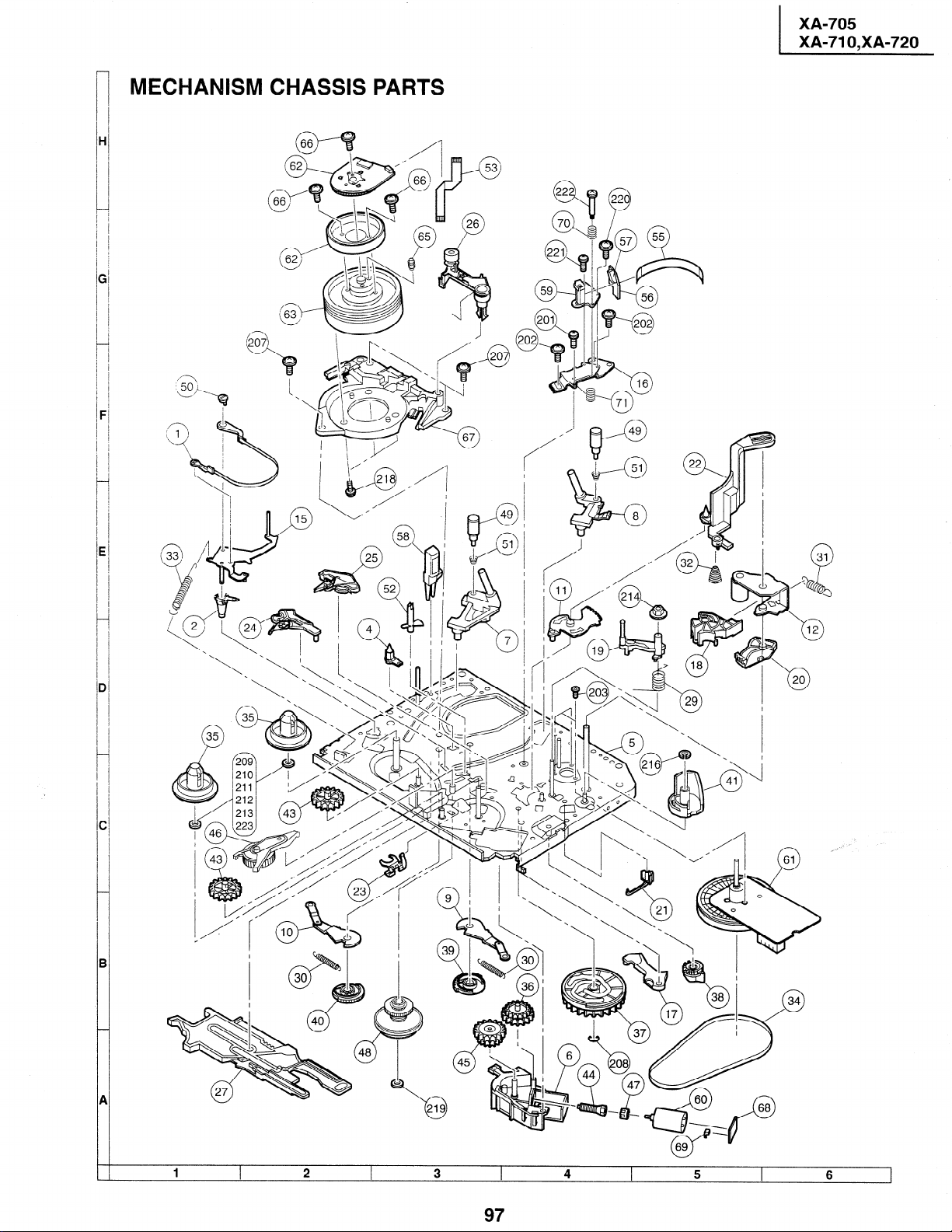
-
MECHANISM CHASSIS PARTS
H
-
6
-
F
-
XA-705
XA-71 O,XA-720
E
-
D
-
c
-
B
-
A
-
-
Page 82

XA-705
XA-71 O,XA-720
CASSETTE HOUSING CONTROL PARTS
I
I
I
I
I
I
I
I
I
I
I
I
I
I
I
I
I
I
I
I
I
I
I
I
I
I
I
I
1
2
3
98
4
5
6
Page 83

,NICAL PARTS
XA-705
XA-71 O,XA-720
1 2 3
99
4 5 6
I
Page 84

XA-705
XA-71 O,XA-720
FRONT PANEL PARTS (XA-705)
1 2
PRECAUTION ON FRONT PANEL SET-UP
Cassette cover
open lever
Before attaching the front
panel in position, make
sure that the cassette cover
open lever is in its right
place (lower-most). If it is
out of position, push it down
with a finger.
Keep the cassette over about
45” open and make sure that
the cassette cover open lever is between the front panel
and the cassette cover. Now
fix the front panel in place.
3
’ ’ About 45”
Do not mount the front
panel with the cassette
cover tilted too open.
Otherwise the cassette
cover might wrongly run
on the cassette housing.
100
502
b
4 5
Removing the cassette compartment cover.
Open the cassette compartment cover
fully.
Remove the center positioner.
Slide the cover to the right.
Slightly bend the cover.
Draw out the left-side rod.
6
Page 85

FRONT PANEL PARTS (XA-710)
_____-__--_________------~---~~~--~~~~~~~~~~~~~~~~-
I
501-8
/
“h
XA-705
XA-71 O,XA-720
-___-__---___--_____~~~~~~~----~~~~~~~~-
1 I 2 I 3 I 4 I
PRECAUTION ON FRONT PANEL SET-UP
Cassette cover
open lever
Before attaching the front
panel in position, make
surethatthecassettecover
open lever is in its right
place (lower-most). If it is
out of position, push it down
with a finger.
Keep the cassette over about
45” open and make sure that
the cassette cover open lever is between the front panel
and the cassette cover. Now
fix the front panel in place.
Cassette cover
Cassette cover
Do not mount the front
panel with the cassette
cover tilted too open.
Otherwise the cassette
cover might wrongly run
on the cassette housing.
101
502
0
5
Removing the cassette compartment cover.
1 Open the cassette compartment cover
fully.
2 Remove the center positioner.
3 Slide the cover to the right.
4 Slightly bend the cover.
5 Draw out the left-side rod.
1
6
I
Page 86

XA-705
XA-71 O,XA-720
FRONT PANEL PARTS (XA-720)
____________________~~~~-~~~~~~~~~-~~~~--~~~-
I
I
I
I
I
I
I
I
I
I
I
I
I
I
1
I
I
I
I
I
I
I
I
j 501-2
19
505 j
I
I
I
&
I
I
___--_-____----__---~~~--~~_~~~~~_
_-________________.
1 I 2
PRECAUTION ON FRONT PANEL SET-UP
Cassette cover
open lever
Before attaching the front
panel in position, make
sure that the cassette cover
open lever is in its right
place (lower-most). If it is
out of position, push it down
with a finger.
Keep the cassette over about
45” open and make sure that
the cassette cover open lever is between the front panel
and the cassette cover. Now
fix the front panel in place.
3 I
” About 45”
Front bane1
Do not mount the front
panel with the cassette
cover tilted too open.
Otherwise the cassette
cover might wrongly run
on the cassette housing.
102
4
5 I 6 I
Removing the cassette compartment cover.
Open the cassette compartment cover
fully.
Remove the center positioner.
Slide the cover to the right.
Slightly bend the cover.
Draw out the left-side rod.
Page 87

XA-705
XA-71 O,XA-720
12. PACKING
n Setting position of
Accessories
TiNS-3250AJZZ
TiNS-3432AJZZ
TCADH0051 AJZZ
TCADH0049AJZZ
QCNW-0298AJZZ
Operation Manual (XA-705)
Operation Manual (XA-71 O/720)
Timer Setting Card (XA-705)
Timer Setting Card (XA-71 O/720)
75 ohm Coaxial Cable
OF THE SET
the Knobs
RF conv. CH. preset at “3” channel
I
i
Infrared R/C Unit
* SPAKXl 012AJZZ
Buffer Material
* SPAKC3776AJZZ (XA-705)
* SPAKC3777AJZZ (XA-710)
* SPAKC3778AJZZ (XA-720)
MARK * : Not Replacement Item
103
BK0005AJZZ
No. Card
Page 88

XA-705
XA-71 O,XA-720
SHARP
COPYRIGHT 0 1998 BY SHARP CORPORATION
ALL RIGHTS RESERVED.
No part of this publication may be reproduced,
stored in a retrieval system, or transmitted in
any form or by any means, electronic, mechanical,
photocopying, recording, or otherwise, without
prior written permission of the publisher.
TQ0492-S
Jul. 1998 Printed in Japan
NA. KG
SHARP CORPORATION
AV Systems Group
Quality & Reliability Control Center
Yaita, Tochigi 329-2193, Japan
 Loading...