

Sharp MX-FNX9,MX-PNX1D,MX-PNX1A,MX-PNX1B,MX-PNX1C Service Manual

TopPage
SERVICE MANUAL
CODE: 00ZMXFNX9/S1E
DIGITAL FULL COLOR
MULTIFUNCTIONAL SYSTEM OPTION
FINISHER / PUNCH MODULE
MX-FNX9
MODEL
CONTENTS
[1] PRODUCT OUTLINE . . . . . . . . . . . . . . . . . . . . . . . . . . . . . . . . . . . 1-1
[2] SPECIFICTIONS . . . . . . . . . . . . . . . . . . . . . . . . . . . . . . . . . . . . . . . 2-1
[3] UNPACKING AND INSTALLATION
* For how to unpacking and installation, refer to the installation manual (00ZMX3100/I1E).
[4] EXTERNAL VIEW AND INTERNAL STRUCTURE . . . . . . . . . . . . . 4-1
[5] OPERATIONAL DESCRIPTIONS . . . . . . . . . . . . . . . . . . . . . . . . . . 5-1
[6] DISASSEMBLY AND ASSEMBLY . . . . . . . . . . . . . . . . . . . . . . . . . . 6-1
[7] MAINTENANCE. . . . . . . . . . . . . . . . . . . . . . . . . . . . . . . . . . . . . . . . 7-1
[8] ADJUSTMENTS . . . . . . . . . . . . . . . . . . . . . . . . . . . . . . . . . . . . . . . 8-1
MX-PNX1A/B/C/D
[9] SELF DIAGNOSTICS AND TROUBLE CODES . . . . . . . . . . . . . . . 9-1
[10] ELECTRICAL SECTION . . . . . . . . . . . . . . . . . . . . . . . . . . . . . . . . 10-1
Parts marked with " " are important for maintaining the safety of the set. Be sure to replace these parts with
specified ones for maintaining the safety and performance of the set.
SHARP CORPORATION
This document has been published to be used
for after sales service only.
The contents are subject to change without notice.

CONTENTS
[1] PRODUCT OUTLINE. . . . . . . . . . . . . . . . . . .1-1
[2] SPECIFICTIONS
1. MX-FNX9 . . . . . . . . . . . . . . . . . . . . . . . . .2-1
2. MX-PNX1A/B/C/D . . . . . . . . . . . . . . . . . .2-2
[3] UNPACKING AND INSTALLATION
* For how to unpacking and installation, refer to the
installation manual (00ZMX3100/I1E).
[4] EXTERNAL VIEW AND INTERNAL
STRUCTURE
1. Identification of each section and
functions . . . . . . . . . . . . . . . . . . . . . . . . . .4-1
[5] OPERATIONAL DESCRIPTIONS
1. Electrical mechanism diagram . . . . . . . . .5-1
2. General. . . . . . . . . . . . . . . . . . . . . . . . . . .5-5
3. Outline of the transport path . . . . . . . . . . .5-5
4. Non-sort mode . . . . . . . . . . . . . . . . . . . . .5-6
5. Offset mode . . . . . . . . . . . . . . . . . . . . . . .5-6
6. Staple mode . . . . . . . . . . . . . . . . . . . . . . .5-7
7. Punching process . . . . . . . . . . . . . . . . . . .5-9
[6] DISASSEMBLY AND ASSEMBLY
1. MX-FNX9 . . . . . . . . . . . . . . . . . . . . . . . . 6-1
2. MX-PNX1A/B/C/D . . . . . . . . . . . . . . . . . 6-11
[7] MAINTENANCE
1. Maintenance system table . . . . . . . . . . . 7-1
[8] ADJUSTMENTS
1. Setting item list . . . . . . . . . . . . . . . . . . . . 8-1
2. Details . . . . . . . . . . . . . . . . . . . . . . . . . . . 8-1
[9] SELF DIAGNOSTICS AND TROUBLE CODES
1. Trouble code and troubleshooting. . . . . . 9-1
[10] ELECTRICAL SECTION
1. Circuit descriptions . . . . . . . . . . . . . . . . 10-1
2. Block diagram . . . . . . . . . . . . . . . . . . . 10-12
3. Actual wiring diagram . . . . . . . . . . . . . 10-14
DIGITAL FULL COLOR
MULTIFUNCTIONAL SYSTEM
MX-2600N/3100N
MX-2600G/3100G
MX-FNX9
[1] PRODUCT OUTLINE
Service Manual
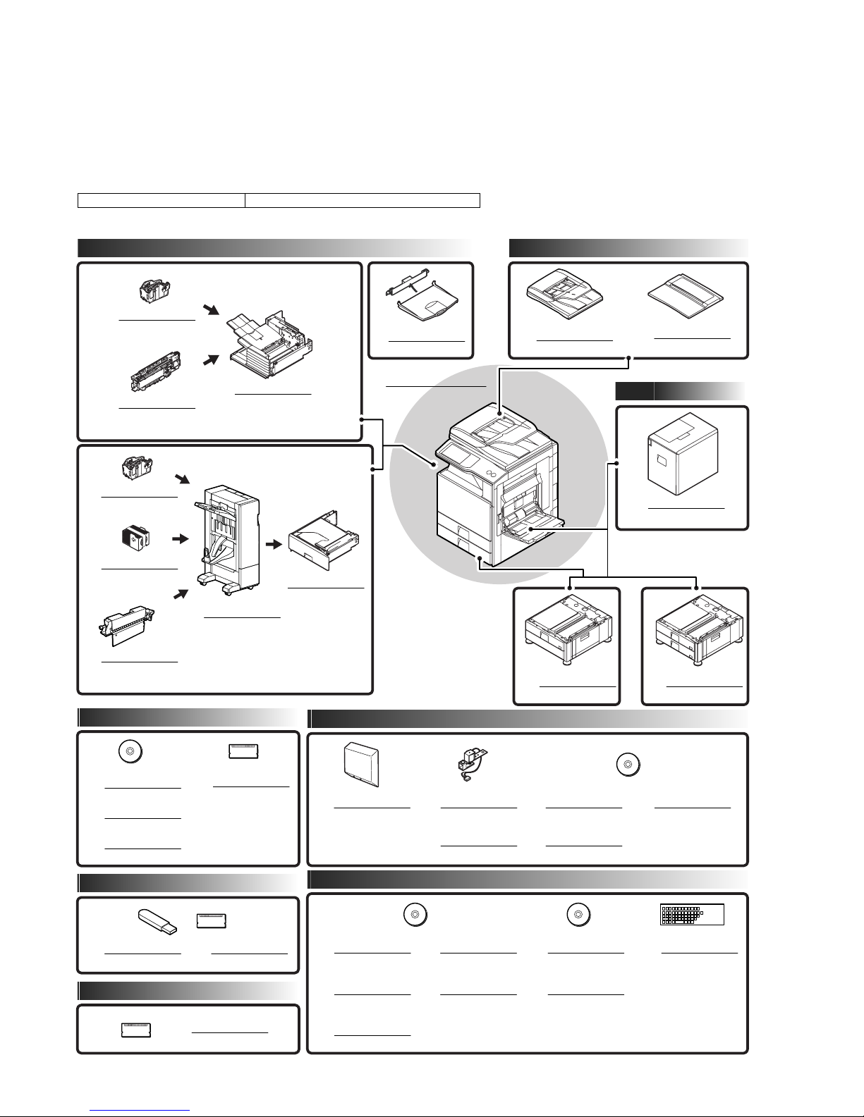
This unit is used by installing to the purpose of this unit is to provide post processing of fax and copy output paper. It is provided with the offset
function which discharges output paper by shifting one by one.
Since it is installed to the center tray section of the main unit, no extra space for installation is required.
1) 3 kinds of auto staple functions: There are 3 kinds of stapling positions. (One position in front, one position backward, 2 positions at the
center).
2
2) Punch function (option): By installing the punch unit, paper can be punched to make binder holes. (Paper of 64 to 128g/m
can be used.
OHP film cannot be used.)
Models enable to install the unit MX-2600G/MX-2600N/MX-3100G/MX-3100N
The finisher requires a staple cartridge as a consumable part. (Staple cartridge (about 5,000 staples x 3 pcs.) MX-SCX1)
Paper exit system Document feeder system
STAPLE CARTRIDGE
12
MX-SCX1
PUNCH MODULE
10
MX-PNX1
A/B/C/D
FINISHER
7
MX-FNX9
EXIT TRAY UNIT
6
MX-TRX1
DIGITAL FULL COLOR
MULTIFUNCTIONAL SYSTEM
MX-2600N/3100N
MX-2600G/3100G
REVERSING
SINGLE PASS FEEDER
1
MX-RPX2
DOCUMENT COVER
2
MX-VRX1
Paper feed system
STAPLE CARTRIDGE
12
MX-SCX1
STAPLE CA
13
11
RTRIDGE
(For saddle)
AR-SC3
PUNCH MODULE
MX-PNX5
A/B/C/D
SADDLE STITCH
FINISHER
9
MX-FN10
Printer expansion
PRINTER
EXPANSION KIT
14
MX-PBX3
PS3 EXPANSION KIT
15
MX-PKX1
XPS EXPANSION KIT
16
MX-PUX1
BARCODE FONT KIT
17
AR-PF1
Authentication/Security
PAPER PASS UNIT
8
MX-RBX3
Image send expansion
FACSIMILE
EXPANSION KIT
18
MX-FXX2
Application/Solution
STAMP UNIT
19
AR-SU1
STAMP CARTRIDGE
20
AR-SV1
STAND/1 x 500 SHEET
PAPER DRAWER
3
MX-DEX6
INTERNET FAX
EXPANSION KIT
21
MX-FWX1
NETWORK SCANNER
EXPANSION KIT
22
MX-NSX1
LARGE CAPACITY TRAY
5
MX-LCX1
STAND/2 x 500 SHEET
PAPER DRAWER
4
MX-DEX7
APPLICATION
INTEGRATION MODULE
23
MX-AMX1
DATA SECURITY KIT
24
MX-FR10U
DATA SECURITY KIT
25
MX-FR10
Memory
EXPANSION
MEMORY BOARD
34
MX-SMX3
26
27
28
SHARPDESK
1 LICENSE KIT
MX-USX1
SHARPDESK
5 LICENSE KIT
MX-USX5
SHARPDESK
10 LICENSE KIT
MX-US10
SHARPDESK
50 LICENSE KIT
29
MX-US50
SHARPDESK
100 LICENSE KIT
30
MX-USA0
MX-FNX9 PRODUCT OUTLINE 1 – 1
APPLICATION
COMMUNICATION MODULE
31
MX-AMX2
EXTERNAL
ACCOUNT MODULE
32
MX-AMX3
33
KEYBOARD
MX-KBX1
MX-FNX9
[2] SPECIFICTIONS
Service Manual
1. MX-FNX9
Type Inner finisher
Loading method Offset tray
Transport speed 26, 31 PPM
Tray type Offset tray
Transport reference Center reference
Paper exit direction Face down
Mode type Non-stapled, stapled
Offset quantity 30mm, 1.2 inch
Stapling 3 kinds (One position in front, one position backward, 2 positions).
Staple supply system Staple sheet cartridge replacement system (Staple cartridge (Approx. 5,000 x 3 pcs.) MX-SCX1)
Staple detection Staple empty detection (Near empty detection: 20 staples remained)
Manual stapling No
External dimensions (W x D x H) 440 x 595 x 205 (mm), 17 21/64 x 23 27/64 x 8 5/64 (inch)
Weight Approx. 13kg (28.7 lbs)
Power source Supplied from the main unit power source. (DC24V, DC5V)
Power consumption 55.2W
Installation/maintenance Installed by service personnel
Optional detection Auto detection supported
Packaged items Parts for mounting, operational sheet, staple directional instruction label, installation cautionary note
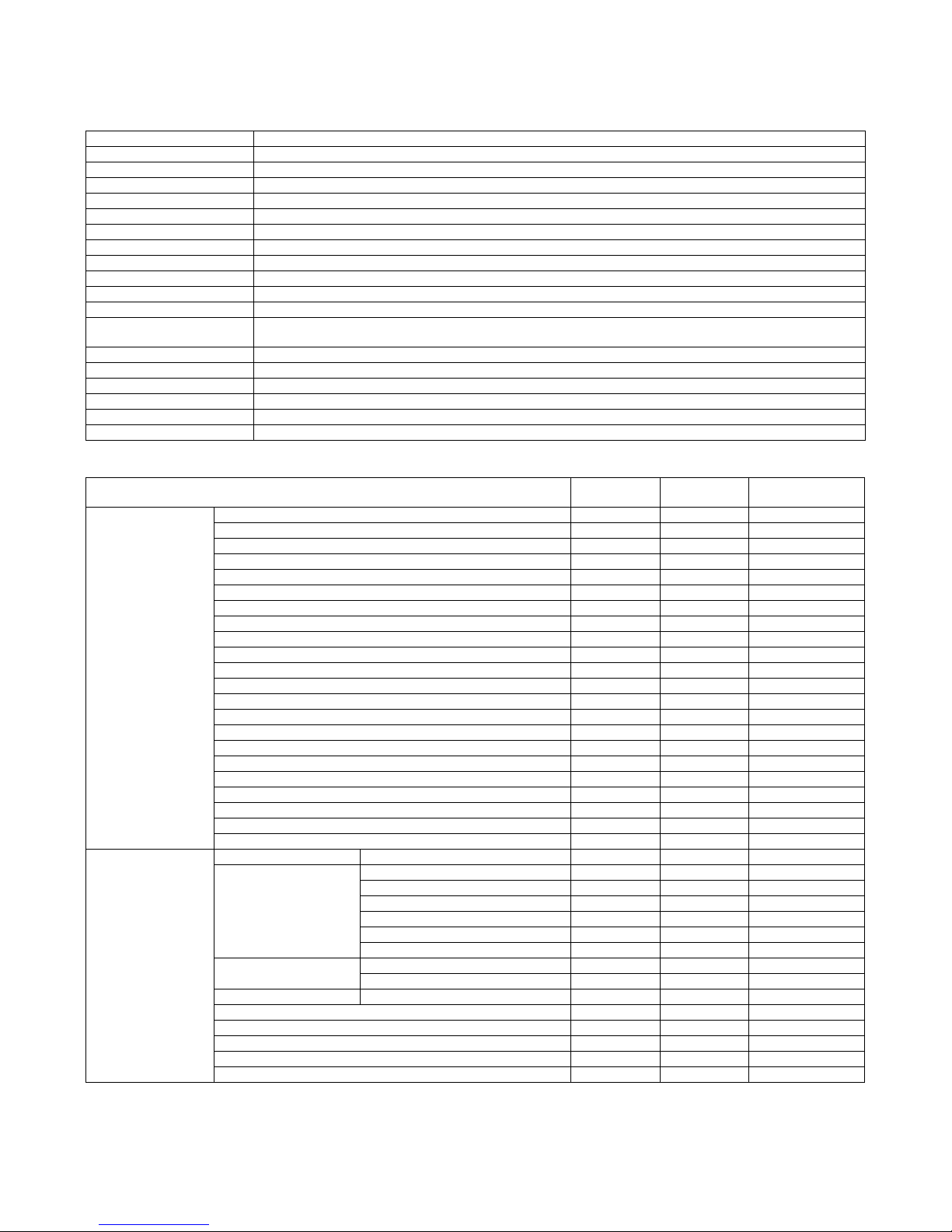
A. Allowable paper size fo paper exit/Weight
(with tray extended: 640 x 595 x 205 (mm), 25 12/64 x 23 27/64 x 8 5/64 (inch))
Allowable
paper size
Paper size 12 x 18 (A3W) Yes - -
11 x 1 7 Yes Yes 30 sheets
8.5 x 14 (216 x 356) Yes Yes 30 sheets
8.5 x 13.5 (216 x 343) Yes Yes 30 sheets
8.5 x 13.4 (216 x 340) Yes Yes 30 sheets
8.5 x 13 (216 x 330) Yes Yes 30 sheets
8.5 x 11 Yes Yes 50 sheets
8.5 x 11R Yes Yes 50 sheets
7.25 x 10.5R Yes - -
5.5 x 8.5R Yes - A3 Yes Yes 30 sheets
B4 Yes Yes 30 sheets
A4 Yes Yes 50 sheets
A4R Yes Yes 50 sheets
B5 Yes Yes 50 sheets
B5R Ye s - A5R Ye s - 8K Yes Yes 30 sheets
16K Yes Yes 50 sheets
16KR Yes - 50 sheets
Envelope *1 Yes - Custom *2 Yes - -
Paper type Thin paper 55 - 59g/m2 13 lb bond - 16 lb bond Yes Yes Yes
Plain paper 60 - 105g/m2 16 lb bond - 28 lb bond Yes Yes Yes
Recycled paper Yes Yes Yes
Colored paper Yes Yes Yes
Letterhead Yes Yes Yes
Printed paper Yes Yes Yes
punched paper Yes Yes Yes
Thick paper 106 - 209g/m2 28 lb bond -110 lb index Yes Yes *3 Yes *4
210 - 256g/m2 110 lb index - 140 lb index Yes Yes *3 Yes *4
Envelope 75 - 90g/m2 Yes - OHP Ye s - label paper Yes - Tab paper *3 Yes - Gloss paper Yes Yes User type 1 - 7 Yes Yes Yes *5
Offset
Allowable paper
quantity for stapling
*1: Supported kinds of envelopes: Monarch/Com-10/DL/C5/Long type 3/ Western type 2/ Western type 4/Long type 2
*2: Custom size support area
~
Tray (supporting soft SW) X: 182 - 432mm (7_1/
~
Manual feed X: 148 - 432mm (5_1/
217) Y: 100 - 297mm (5_1/~211_5/8)
417) Y: 132 - 297mm (5_1/~411_5/8)
*3: Thick paper (129g/m2 or above: Out of performance assurance)
MX-FNX9 SPECIFICTIONS 2 – 1
*4: Thick paper (In the cover paper mode, allowable only 2 (in total of the front cover paper and the back cover paper) + plain paper.))
*5: Follows the paper type registration setting.
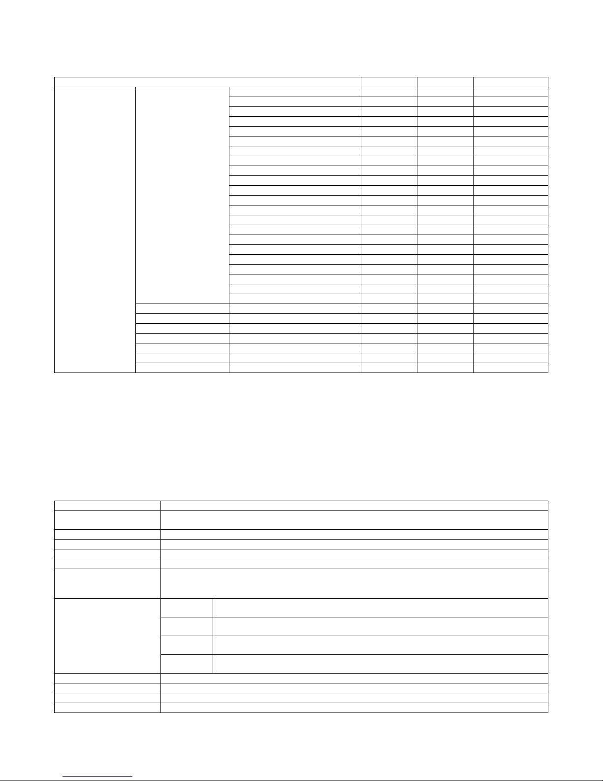
B. Allowable load quantity for each size
Function/Mode Non-offset Offset Staple
Paper size Plain paper
(60 - 105g/m2 paper)
Envelope 10*3 No No
Thin paper 500 *6 500 *6 500 *6
Thick paper 500 *6 500 *6 Cover only
gloss paper A4/8.5 x 11 500 *6 500 *6 No
Tab paper A4/8.5 x 11 100 *7 No No
Label paper A4/8.5 x 11 100 *7 No No
OHP A4/8.5 x 11 100 *7 No No
*1: 250 sheets or height of 35.5mm or less
*2: 500 sheets or height of 71mm or less
*3: Up to 10 envelopes can be loaded on the load tray.
*4: 250 sheets or 30 sets, or height of 35.5mm or less
*5: 500 sheets or 30 sets or height of 71mm or less
*6: Similarly with plain paper, the load capacity of thin paper, heavy paper, and glossy paper is limited to the earliest reach of the above number
of sheets or the limited height.
*7: 100 sheets or height of 35.5mm or less
A3W 250 *1 No No
A3 250 *1 250 *1 250 *4
B4 250 *1 250 *1 250 *4
A4 500 *2 500 *2 500 *5
A4R 500 *2 500 *2 500 *5
B5 500 *2 500 *2 500 *5
B5R 500 *2 No No
A5R 500 *2 No No
12 x 18 250 *1 No No
11 x 17 250 *1 250 *1 250 *4
8.5 x 14 250 *1 250 *1 250 *4
8.5 x 13.5 (216 x 343) 250 *1 250 *1 250 *4
8.5 x 13.4 (216 x 340) 250 *1 250 *1 250 *4
8.5 x 13 (216 x 330) 250 *1 250 *1 250 *4
8.5 x 11 500 *2 500 *2 500 *5
8.5 x 11R 500 *2 500 *2 500 *5
7.25 x 10.5R 500 *2 No No
5.5 x 8.5R 500 *2 No No
8K 250 *1 250 *1 250 *4
16K 500 *2 500 *2 500 *5
16KR 500 *2 No 500 *5
Special (Custom) 250 *1 No No
2. MX-PNX1A/B/C/D
Type Punch unit for the inner finisher
Punch type 2 holes / 3 holes / 4 holes / 4 holes (wide)
A punch unit that provides all of these 4 types can be installed.
Transport speed 23, 27, 35, 45 PPM
Transport reference Center reference
Punch dust full detection YES (Lever system)
Paper exit direction Face down
Paper weight Plain paper: 60 to 105g/m
Thin paper: 55 to 59g/m
Heavy paper: 106 to 209g/m
Punchable paper size 2 holes
(MX-PNX1A)
3 holes *1
(MX-PNX1B)
4 holes
(MX-PNX1C)
4 holes (wide)
(MX-PNX1D)
Power source Supplied from the inner finisher. (DC24V, DC5V)
External dimensions (W x D x H) 105 x 518 x 170 (mm), 4 9/64 x 20 25/64 x 6 45/64 (inch)
Weight Approx. 3.5kg (7.7 lbs)
Packaged items Parts for mounting, instructional label for punch direction, instructional label for garbage pickup, installation cautionary note
*1: Auto switching: 2 holes/3 holes
2
(16 to 28 lbs)
2
(15 to 16 lbs)
2
(28 to 56 lbs)
A3, B4, A4, A4R, B5, B5R, 11" x 17", 8.5" x 14", 8.5" x 13", 8.5" x 11", 8.5" x 11"R, 8K, 16K, 16KR
3 holes: A3, A4, 11" x 17", 8.5" x 11"
2 holes: 8.5" x 14", 8.5" x 13", 8.5" x 11"R
A3, A4
A3, B4, A4, A4R, B5, B5R, 11" x 17", 8.5" x 14", 8.5" x 13", 8.5" x 11", 8.5" x 11"R
MX-FNX9 SPECIFICTIONS 2 – 2
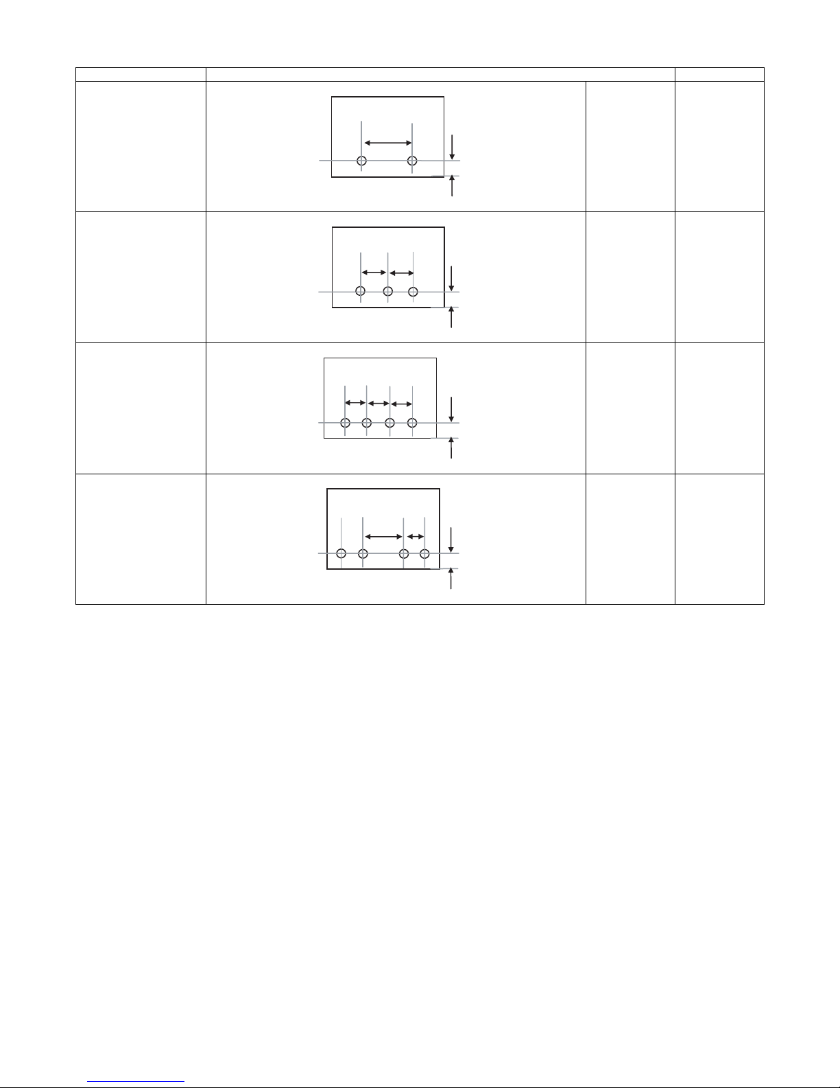
Kind of hole punch
A
A
A
A
A
A
A
Kind Hole position Hole size
2 holes (MX-PNX1A) A: 80±1mm
B: 12±3mm
B
φ6.5mm
3 holes (MX-PNX1B) A: 108±1mm
B: 12±3mm
B
4 holes (MX-PNX1C) A: 80±1mm
B: 12±3mm
B
4 holes (wide) (MX-PNX1D) A: 70±1mm
B: 12±3mm
C: 21±1mm
C
B
φ8.0mm
φ6.5mm
φ6.5mm
MX-FNX9 SPECIFICTIONS 2 – 3
MX-FNX9
[4] EXTERNAL VIEW AND INTERNAL STRUCTURE
Service Manual
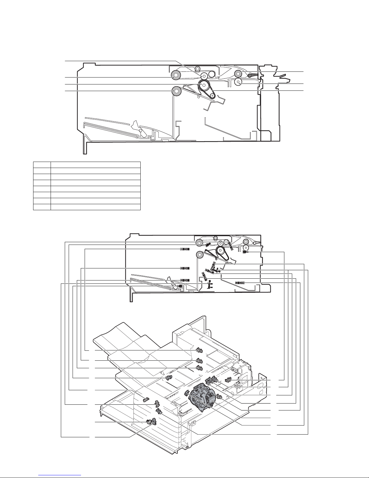
1. Identification of each section and functions
A. Internal structure
1
2
3
4
No. Name
1 Paper exit roller
2 Bundle exit paper transport roller
3 Paper exit roller
4 Bundle exit paper transport roller
5 Inlet port paper transport roller
6 Inlet port paper transport roller
7 Take-up belt
B. Sensors and switches
(1) MX-FNX9
5
6
7
1
2
3
4
12
13
14
7
MX-FNX9 EXTERNAL VIEW AND INTERNAL STRUCTURE 4 – 1
11
10
5
6
15
16,17,18
8
9
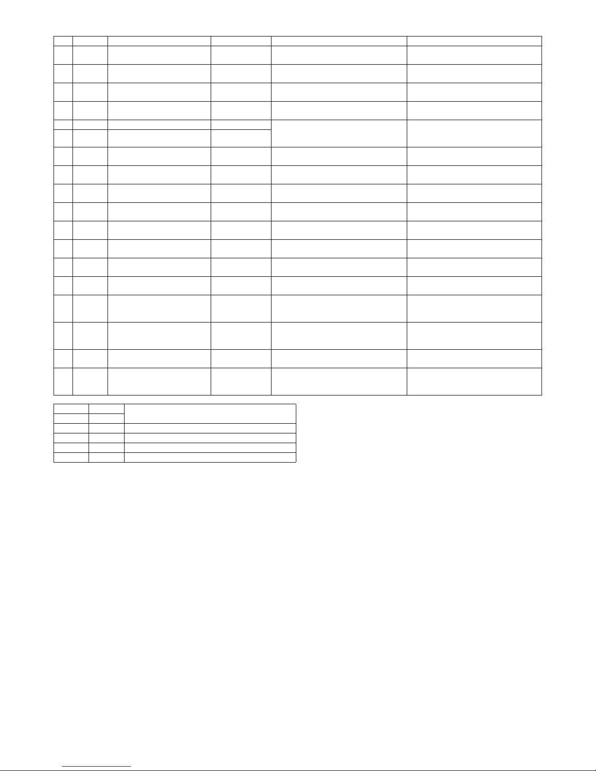
No. Signal Name Type Function/Operation Output
1 FULD Tray upper limit sensor Photo interrupter Detects the upper limit position of the
2 FMLLD Tray intermediate lower limit
sensor
3 FLLD Tray lower limit sensor Photo interrupter Detects the lower limit position of the
4 FBED Tray paper empty sensor Photo interrupter Detects paper empty in the paper load
5 FSLD1 Paper surface sensor 1 Photo interrupter Detects the surface position of paper on
6 FSLD2 Paper surface sensor 2 Photo interrupter
7 FSTHPD Stapler HP sensor Photo interrupter Detects the home position of the stapler
8 FSTPD Empty sensor Photo interrupter Detects paper empty on the process tray. TP8 is driven to “H” when paper is
9 FFJHPD Alignment plate HP sensor F Photo interrupter Detects the home position of the alignment
10 FRJHPD Alignment plate HP sensor R Photo interrupter Detects the home position of the alignment
11 FED Inlet port sensor Photo interrupter Detects paper in the inlet port of the
12 FRLD Roller up/down sensor Photo interrupter Detects the upper standby position of up/
13 FBRD Take-up belt sensor Photo interrupter Detects up/down positions of the take-up
14 FDSW Front cover switch Photo interrupter Detects open/close of the jam release
15 FJPD Alignment plate position sensor Photo interrupter Detects entry of the process section rear
16 FSHPD Stapler home sensor Detects the home position of the stapling
17 FSD Staple empty sensor Detects staple empty. (Sensor built in the
18 FSTD Self priming sensor Detects the staple feed is completed and it
Photo interrupter Detects the intermediate position of the
paper load tray up/down shift area.
paper load tray up/down shift area.
paper load tray up/down shift area.
tray.
the tray in combination of the both sensors
outputs.
unit in F/R direction shift.
guide on F side.
guide on R side.
finisher.
down movement of the bundle exit roller.
belt.
cover in the front section.
edge stopper into the opening of the
stapler and inhibits stapling.
mechanism. (Sensor built in the stapler
unit)
stapler unit)
is ready for stapling. (Sensor built in the
stapler unit)
TP1 is driven to “L” at the upper limit
position.
TP2 is driven to “L” at the intermediate
position.
TP3 is driven to “L” at the lower limit
position.
TP4 is driven to “L” when paper is
provided.
*Refer to the separate table outside the
column.
TP7 is driven to “H” at the home position.
provided.
TP9 is driven to “L” at the home position.
TP10 is driven to “L” at the home position.
TP11 is driven to “H” when paper is
provided.
TP12 is driven to “L” when the roller
reaches the upper standby position.
TP13 is driven to “L” when the take-up belt
is on the upper side.
TP15 is driven to “L” when the cover is
closed.
TP50 is driven to “L” when the stopper
enters the opening of the stapler.
TP51 is driven to “H” at the home
(standby) position.
TP53 is driven to “L” when staple empty.
TP52 is driven to “H” when in the ready
state.
FSLD1 FSLD2
TP5 TP6
“L” “H” The paper detection lever is in the save position.
“H” “H” The paper surface is upper than the reference level.
“H” “L” The paper surface is at the reference level.
“L” “L” The paper surface is lower than the reference level.
State
MX-FNX9 EXTERNAL VIEW AND INTERNAL STRUCTURE 4 – 2
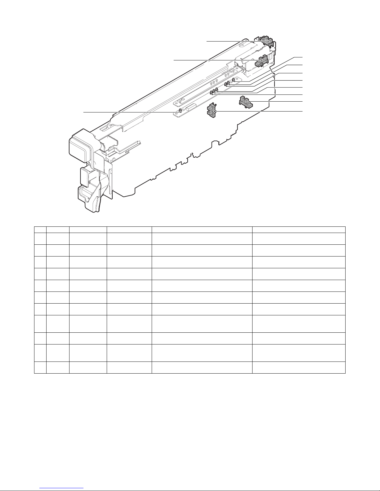
(2) MX-PNX1A/B/C/D
3
2
11
10
9
8
7
6
4
5
No. Signal Name Type Function/Operation Output
1 FPDD Full sensor Photo interrupter Detects full of the punch dust container. When full, TP2 on the punch PWB remains
2 FPHPD Punch position
sensor
3 FPRPD Rear position
sensor
4 FPSHPD Horizontal shift
HP sensor
5 FPPEND Paper rear edge
sensor
6 FPPD1 Paper horizontal
resist sensor 1
7 FPPD2 Paper horizontal
resist sensor 2
8 FPPD3 Paper horizontal
resist sensor 3
9 FPPD4 Paper horizontal
resist sensor 4
10 FPPD5 Paper horizontal
resist sensor 5
11 FPPD6 Paper horizontal
resist sensor 6
Photo interrupter Detects the home position of the punch up/down
Photo interrupter Detects the lower limit position of 3-hole side up/
Photo interrupter Detects the home position in the punch position
Transmission type
sensor
Transmission type
sensor
Transmission type
sensor
Transmission type
sensor
Transmission type
sensor
Transmission type
sensor
Transmission type
sensor
shift.
down shift in 2/3-hole punching.
horizontal resist correction mechanism.
Detects the lead edge and the rear edge of paper
to be punched.
Detects the paper edge in the rear side of B5R or
7.25" x 10" R size width direction of the machine.
Detects the paper edge in the rear side of 16K-R
size width direction of the machine.
Detects the paper edge in the rear side of 8.5"
x14", 8.5" x 11"R, 8.5" x 13", or A4R size width
direction of the machine.
Detects the paper edge in the rear side of B4 or
B5 size width direction of the machine.
Detects the paper edge in the rear side of 11" x
17", 8.5" x 11", 8K, or 16K size width direction of
the machine.
Detects the paper edge in the rear side of A3 or
A4 size width direction of the machine.
“H” level.
TP47 on the control PWB of the inner finisher
is driven to “H” at the home position.
TP48 on the control PWB of the inner finisher
is driven to “H” at the lower limit position.
TP49 on the control PWB of the inner finisher
is driven to “H” at the home position.
TP54 on the control PWB of the inner finisher
is driven to “L” when paper is provided.
TP55 on the control PWB of the inner finisher
is driven to “L” when paper is provided.
TP55 on the control PWB of the inner finisher
is driven to “L” when paper is provided.
TP55 on the control PWB of the inner finisher
is driven to “L” when paper is provided.
TP55 on the control PWB of the inner finisher
is driven to “L” when paper is provided.
TP55 on the control PWB of the inner finisher
is driven to “L” when paper is provided.
TP55 on the control PWB of the inner finisher
is driven to “L” when paper is provided.
1
MX-FNX9 EXTERNAL VIEW AND INTERNAL STRUCTURE 4 – 3
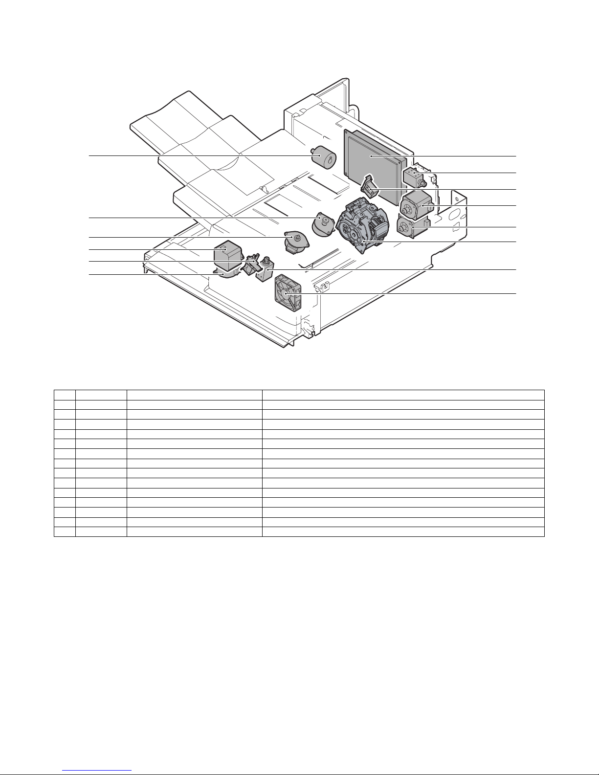
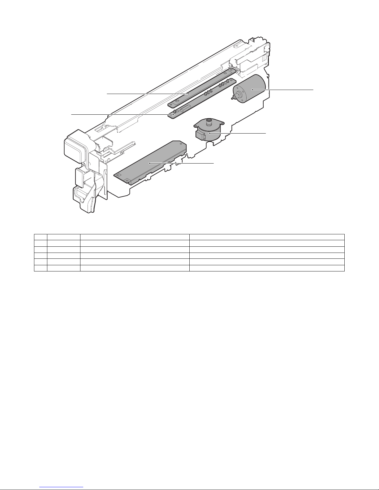
C. Motors, solenoids, and PWB
(1) MX-FNX9
3
14
12
9
8
5
7
4
6
1
11
2
10
13
No. Signal Name Function
1 FFSM Staple motor Drives the stapling mechanism. (Stapler unit built-in motor)
2 FSM Staple shift motor Shifts the stapler unit in the F/R direction.
3 FTLM Tray motor Drives the paper load tray up/down.
4 FFJM Alignment motor F Drive the alignment guide on the F side.
5 FRJM Alignment motor R Drive the alignment guide on the R side.
6 FSWM Roller upper/lower roller Drives the bundle exit roller up/down.
7 FAM Bundle exit motor Drives the bundle exit roller and the paddle.
8 FRM Transport motor Drives the inlet port roller, the feed roller, and the take-up belt.
9 FPDS Paddle one-rotation solenoid Trigger solenoid for paddle one-rotation.
10 FSLS Paper surface detection solenoid Drives the lever for paper holding and detection of the tray paper surface.
11 FBRS Belt separation solenoid Trigger solenoid for up/down shift of the take-up belt.
12 FINRPS Flapper solenoid Drives the flapper to select the entry path between the finisher inside and the reverse path.
13 FFAN Fan Cools the inlet port of the finisher.
14 – Control PWB Controls the inner finisher.
MX-FNX9 EXTERNAL VIEW AND INTERNAL STRUCTURE 4 – 4
(2) MX-PNX1A/B/C/D
5
4
2
3
No. Signal Name Function
1 FPNM Punch motor Drives the punch unit up/down.
2 FPSM Punch horizontal resist motor Shifts the punch unit to the center of paper.
3 – Punch PWB Controls the punch unit.
4 – LED light emitting PWB Detects the paper rear edge and the punch horizontal resist.
5 – LED light receiving PWB Detects the paper rear edge and the punch horizontal resist.
1
MX-FNX9 EXTERNAL VIEW AND INTERNAL STRUCTURE 4 – 5
MX-FNX9
[5] OPERATIONAL DESCRIPTIONS
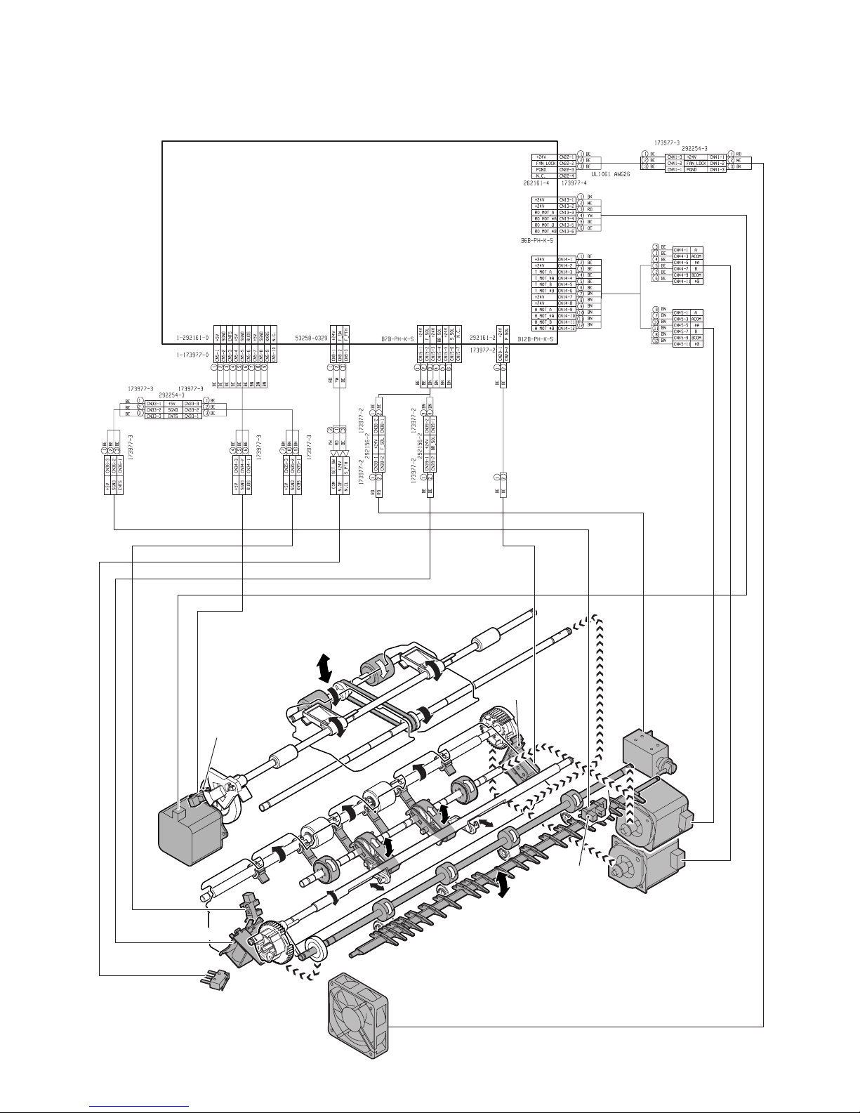
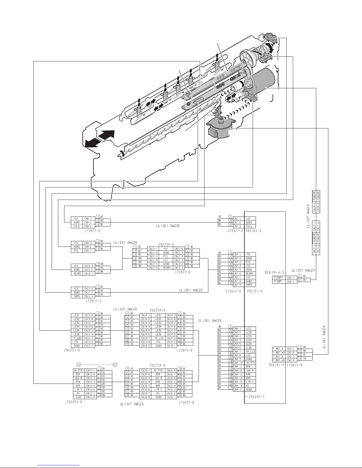
1. Electrical mechanism diagram
A. Transport, paper exit section
PCB-CONT
PF4141K200
Service Manual
FRLD
FSWM
FBRD
FBRS
FDSW
FPDS
FINRPS
FRM
FED
FAM
FFAN
MX-FNX9 OPERATIONAL DESCRIPTIONS 5 – 1
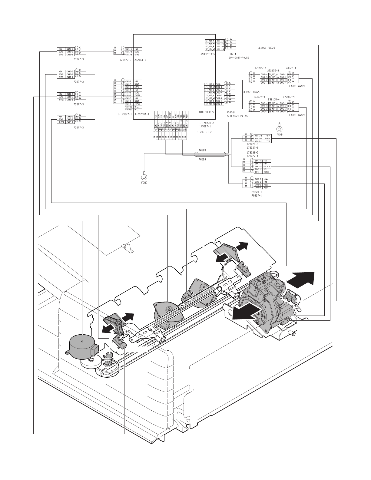
B. Staple section and aligment section
PCB-CONT
PF4141K200
FSM
FSTHPD
FFJHPD
FFJM
FSTPD
FRJHPD
FRJM
FJPD
FFSM
FSHPD(*HP)
FSD(LS)
FSTD(*READY)
MX-FNX9 OPERATIONAL DESCRIPTIONS 5 – 2
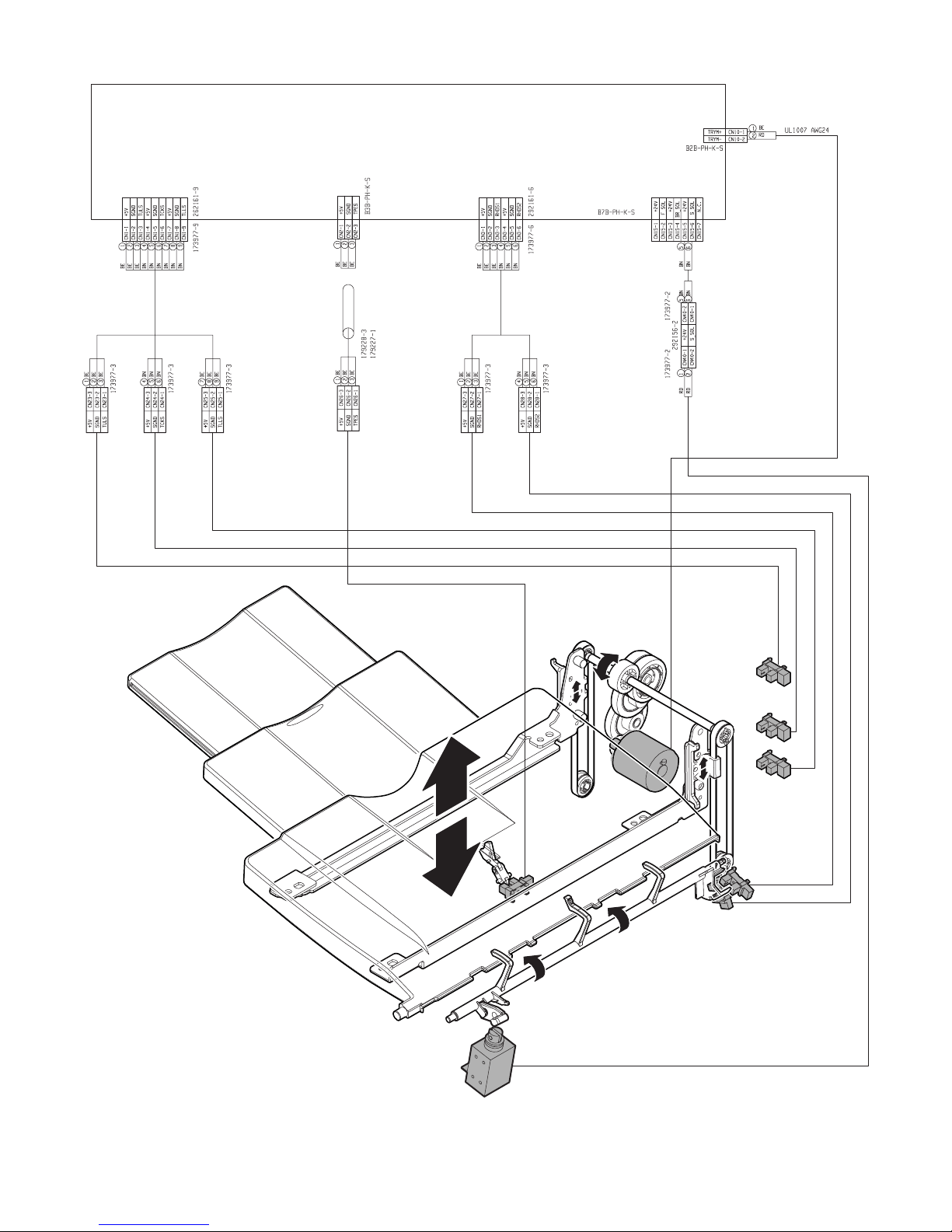
C. Paper exit tray section
PCB-CONT
PF4141K200
FBED
FSLS
FTLM
FULD
FMLLD
FLLD
FSLD1
FSLD2
MX-FNX9 OPERATIONAL DESCRIPTIONS 5 – 3
D. Punch unit (MX-PNX1A/B/C/D)
FPPEND
FPDD
FPPD1~FPPD6
FPRPD
FPHPD
FPNM
FPSHPD
FPSM
PCB-PUNCH
YA1035K200
MX-FNX9 OPERATIONAL DESCRIPTIONS 5 – 4
2. General
This chapter describes operations of the inner finisher. The major operation modes are as follows:
• Non-sort mode
• Offset mode
• Staple mode
• Non-sort mode + punch
• Offset mode + punch
• Staple mode + punch
In this chapter, the basic operations of the non-sort mode, the offset mode, and the staple mode are described.
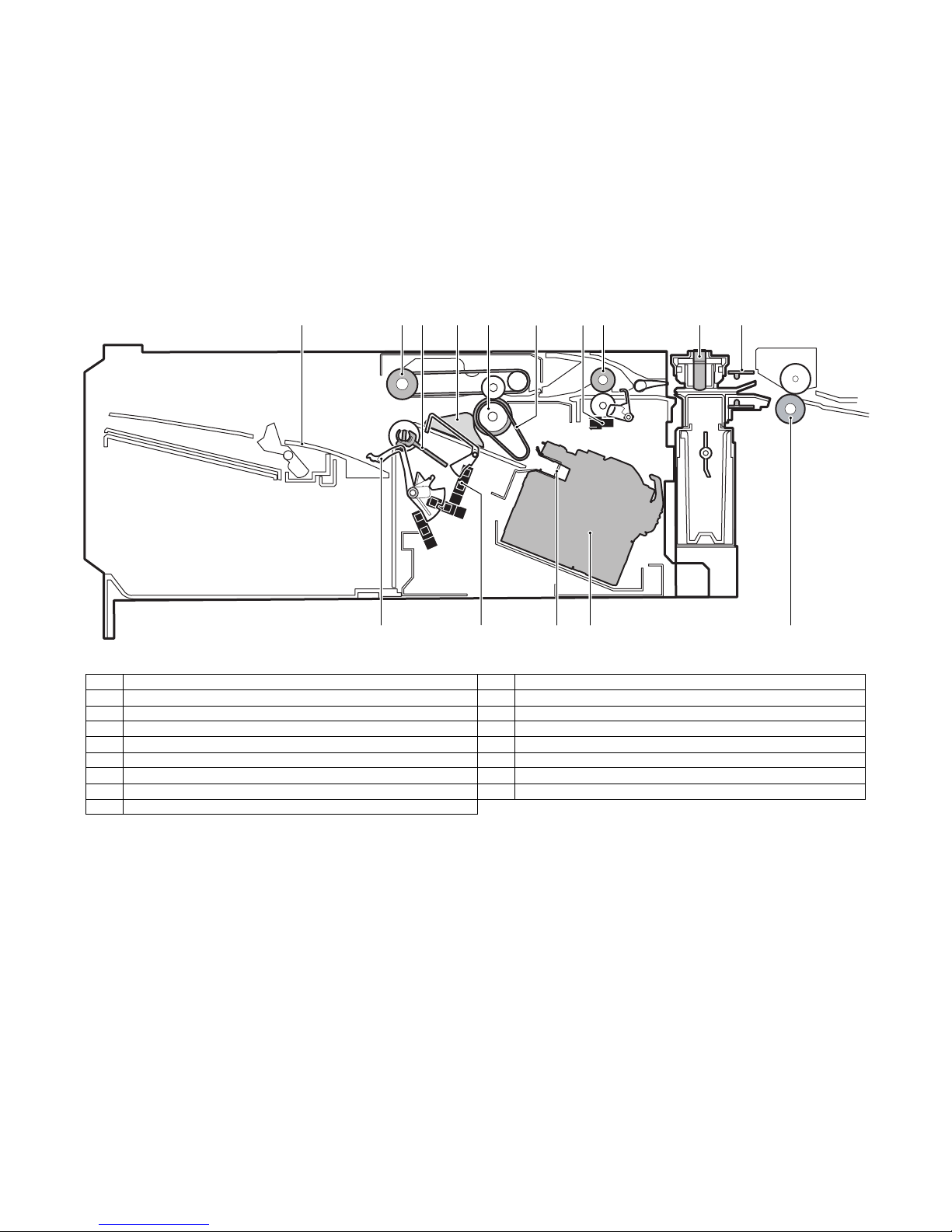
3. Outline of the transport path
The outline of the path is shown below.
1345678910
No. Name No. Name
1 Tray 9 Punch pin
2 Bundle exit roller 10 Paper rear edge sensor (FPPEND)
3 Paddle 11 Main unit paper exit roller
4 Alignment plate 12 Stapler
5 Paper exit roller 13 Paper stopper
6 Take-up belt 14 Empty sensor (FSTPD)
7 Inlet port sensor (FED) 15 Paper holding lever
8 Inlet port roller
2
1112131415
MX-FNX9 OPERATIONAL DESCRIPTIONS 5 – 5
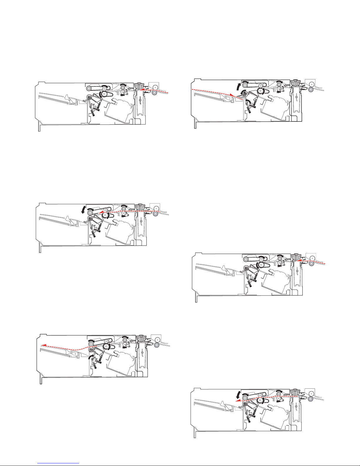
4. Non-sort mode
When the operation mode command is received from the copier,
the finisher makes the finisher operation status command the JOB
and starts the transport operation.
A. Reception of paper discharged from the main
unit
1) The transport motor (FRM) is driven at the paper exit speed of
the main unit to receive paper from the main unit.
2) Immediately after the paper rear edge passes the bundle exit
roller, the paddle one-rotation solenoid (FPDS) is turned ON to
take-up the paper falling onto the tray.
3) When paper is transported by 10mm after the paper rear edge
passes the bundle exit roller, the bundle exit motor (FAM) is
accelerated to 200mm/sec. Just before the paddle passes the
load tray, the paper surface detection solenoid (FSLS) is
turned ON to hold the paper discharged by the paper holding
lever.
2) After turning ON the inlet port sensor (FED), the roller up/down
motor (FSWM) is driven to lower the bundle exit roller. The
bundle exit motor (FAM) is driven at the paper exit speed of
the main unit to drive the bundle exit roller. When the paper
width is 210mm or more, the alignment motor F (FFJM) and
the alignment motor R (FRJM) are driven by turning ON the
inlet port sensor (FED) to shift the alignment plate to 15mm
inside the paper and put it under the paper.
3) In the case of the punch mode, punching is performed as
described in "7. Punching process."
B. Paper exit
1) After the paper rear edge passes the paper exit roller of the
main unit, the transport motor (FRM) and the bundle exit motor
(FAM) are accelerated to 480mm/sec. When the paper rear
edge passes the inlet port sensor (FED) and then transport of
a certain amount is made, the alignment plate is shifted to the
home position.
Before the paper rear edge passes the bundle exit roller, the
paper surface detection solenoid (FSLS) is turned OFF and
the bundle exit roller speed is decelerated to 100mm/sec at the
same time, performing paper exit deceleration of paper.
4) When the paddle rotates one turn, the bundle exit motor (FAM)
is stopped.
5) When there is next paper, repeat the procedures from "A-1)."
6) When there is no next paper, the actuators are turned OFF
and the finisher operation status command is set to READY,
and the transport operation is terminated.
5. Offset mode
When the operation mode command is received from the copier,
the finisher makes the finisher operation status command the JOB
and starts the transport operation.
A. Reception of paper discharged from the main
unit
1) The transport motor (FRM) is driven at the paper exit speed of
the main unit to receive paper from the main unit. When the
paper length is 216mm or less, the paper exit speed of the second and later sheets from the main unit is 280mm/sec.
B. Paper take-up and alignment
1) For the first sheet of a bundle, the inlet port sensor (FED) is
turned ON and the roller up/down motor (FSWM) is driven to
lower the bundle exit roller. The bundle exit motor (FAM) is
driven at the paper exit speed of the main unit to drive the bundle exit roller.
In addition, the alignment motor F (FFJM) and the alignment
motor R (FRJM) are driven by turning ON the inlet port sensor
(FED) to shift the alignment plate to 15mm outside the paper,
and enter the standby state. After transport of a certain
amount, the roller up/down motor (FSWM) is driven to lift the
bundle exit roller, stopping the bundle exit motor (FAM).
MX-FNX9 OPERATIONAL DESCRIPTIONS 5 – 6

2) For the second and later sheets of a bundle, the inlet port sensor (FED) turns ON and a certain amount is transported, and
then the alignment motor F (FFJM) and the alignment motor R
(FRJM) are driven to shift the alignment plate to 15mm outside
the paper and to put it under the standby state.
3) After the paper rear edge passes the paper exit roller of the
main unit, the transport motor (FRM) is accelerated to 480mm/
sec.
4) In the punch mode, punching is performed as described in "7.
Punching process."
5) When the paper rear edge passes the inlet port sensor (FED)
and a certain amount is transported, the roller up/down motor
(FSWM) is driven to lower the bundle exit roller and the bundle
exit motor (FAM) is driven for a certain amount in the take-up
direction at the paper exit speed of the main unit to take up
paper to the process tray. In addition, the belt separation solenoid (FBRS) is turned ON to lower the take-up belt.
6) After completion of take-up, the roller up/down motor (FSWM)
is driven to lift the bundle exit roller. The alignment motor F
(FFJM) and the alignment motor R (FRJM) are driven for a certain amount to align paper in the process tray. If there are two
or more sheets to be aligned, the procedures are repeated
from "A-1)" for the specified number of sheets. However, the
paper exit operation of "C. Aligned paper exit" is performed for
every 3 sheets.
2) After transport of paper by a certain amount, the alignment
motor F (FFJM) and the alignment motor R (FRJM) are driven
to shift the alignment plate to the home position.
3) When the paper rear edge passes the empty sensor (FSTPD),
the paper surface detection solenoid (FSLS) is turned OFF
and the bundle exit roller speed is decelerated to 100mm/sec
at the same time, decelerating the paper exit operation.
4) Immediately after the paper rear edge passes the bundle exit
roller, the paddle one-rotation solenoid (FPDS) is turned ON to
take up paper falling onto the tray.
5) When the paper rear edge passes the bundle exit roller and
the paper is transported for 10mm, the bundle exit motor
(FAM) is accelerated to 200mm/sec. Before the paddle passes
the load tray, the paper surface detection solenoid (FSLS) is
turned ON to hold the discharged paper with the paper holding
lever.
C. Aligned paper exit
1) After completion of alignment, the belt separation solenoid
(FBRS) is turned ON to lift the take-up belt. The alignment
motor F (FFJM) and the alignment motor R (FRJM) are driven
to separate paper from the alignment plate by 1mm. In addition, the roller up/down motor (FSWM) is driven to lower the
bundle exit roller. The bundle exit motor (FAM) is started at the
speed of 450mm/sec and paper in the process tray is discharged.
6) When the paddle rotates one turn, the bundle exit motor (FAM)
is stopped.
7) When there is next paper, the procedures are repeated from
"A-1)."
8) When there is no next paper, the actuators are turned OFF and
the finisher operation status command is set to READY to terminate the transport operation.
6. Staple mode
When the operation mode command is received from the copier,
the finisher makes the finisher operation status command the JOB
and starts the transport operation.
A. Reception of paper discharged from the main
unit
1) The transport motor (FRM) is driven at the paper exit speed of
the main unit to receive paper from the main unit. When the
paper length is 216mm or less, the paper exit speed of the second and later sheets from the main unit is 280mm/sec.
MX-FNX9 OPERATIONAL DESCRIPTIONS 5 – 7
 Loading...