

Page 1

TopPage
SERVICE MANUAL
CODE: 00ZMXFNX9/S1E
DIGITAL FULL COLOR
MULTIFUNCTIONAL SYSTEM OPTION
FINISHER / PUNCH MODULE
MX-FNX9
MODEL
CONTENTS
[1] PRODUCT OUTLINE . . . . . . . . . . . . . . . . . . . . . . . . . . . . . . . . . . . 1-1
[2] SPECIFICTIONS . . . . . . . . . . . . . . . . . . . . . . . . . . . . . . . . . . . . . . . 2-1
[3] UNPACKING AND INSTALLATION
* For how to unpacking and installation, refer to the installation manual (00ZMX3100/I1E).
[4] EXTERNAL VIEW AND INTERNAL STRUCTURE . . . . . . . . . . . . . 4-1
[5] OPERATIONAL DESCRIPTIONS . . . . . . . . . . . . . . . . . . . . . . . . . . 5-1
[6] DISASSEMBLY AND ASSEMBLY . . . . . . . . . . . . . . . . . . . . . . . . . . 6-1
[7] MAINTENANCE. . . . . . . . . . . . . . . . . . . . . . . . . . . . . . . . . . . . . . . . 7-1
[8] ADJUSTMENTS . . . . . . . . . . . . . . . . . . . . . . . . . . . . . . . . . . . . . . . 8-1
MX-PNX1A/B/C/D
[9] SELF DIAGNOSTICS AND TROUBLE CODES . . . . . . . . . . . . . . . 9-1
[10] ELECTRICAL SECTION . . . . . . . . . . . . . . . . . . . . . . . . . . . . . . . . 10-1
Parts marked with " " are important for maintaining the safety of the set. Be sure to replace these parts with
specified ones for maintaining the safety and performance of the set.
SHARP CORPORATION
This document has been published to be used
for after sales service only.
The contents are subject to change without notice.
Page 2

CONTENTS
[1] PRODUCT OUTLINE. . . . . . . . . . . . . . . . . . .1-1
[2] SPECIFICTIONS
1. MX-FNX9 . . . . . . . . . . . . . . . . . . . . . . . . .2-1
2. MX-PNX1A/B/C/D . . . . . . . . . . . . . . . . . .2-2
[3] UNPACKING AND INSTALLATION
* For how to unpacking and installation, refer to the
installation manual (00ZMX3100/I1E).
[4] EXTERNAL VIEW AND INTERNAL
STRUCTURE
1. Identification of each section and
functions . . . . . . . . . . . . . . . . . . . . . . . . . .4-1
[5] OPERATIONAL DESCRIPTIONS
1. Electrical mechanism diagram . . . . . . . . .5-1
2. General. . . . . . . . . . . . . . . . . . . . . . . . . . .5-5
3. Outline of the transport path . . . . . . . . . . .5-5
4. Non-sort mode . . . . . . . . . . . . . . . . . . . . .5-6
5. Offset mode . . . . . . . . . . . . . . . . . . . . . . .5-6
6. Staple mode . . . . . . . . . . . . . . . . . . . . . . .5-7
7. Punching process . . . . . . . . . . . . . . . . . . .5-9
[6] DISASSEMBLY AND ASSEMBLY
1. MX-FNX9 . . . . . . . . . . . . . . . . . . . . . . . . 6-1
2. MX-PNX1A/B/C/D . . . . . . . . . . . . . . . . . 6-11
[7] MAINTENANCE
1. Maintenance system table . . . . . . . . . . . 7-1
[8] ADJUSTMENTS
1. Setting item list . . . . . . . . . . . . . . . . . . . . 8-1
2. Details . . . . . . . . . . . . . . . . . . . . . . . . . . . 8-1
[9] SELF DIAGNOSTICS AND TROUBLE CODES
1. Trouble code and troubleshooting. . . . . . 9-1
[10] ELECTRICAL SECTION
1. Circuit descriptions . . . . . . . . . . . . . . . . 10-1
2. Block diagram . . . . . . . . . . . . . . . . . . . 10-12
3. Actual wiring diagram . . . . . . . . . . . . . 10-14
Page 3
DIGITAL FULL COLOR
MULTIFUNCTIONAL SYSTEM
MX-2600N/3100N
MX-2600G/3100G
MX-FNX9
[1] PRODUCT OUTLINE
Service Manual
This unit is used by installing to the purpose of this unit is to provide post processing of fax and copy output paper. It is provided with the offset
function which discharges output paper by shifting one by one.
Since it is installed to the center tray section of the main unit, no extra space for installation is required.
1) 3 kinds of auto staple functions: There are 3 kinds of stapling positions. (One position in front, one position backward, 2 positions at the
center).
2
2) Punch function (option): By installing the punch unit, paper can be punched to make binder holes. (Paper of 64 to 128g/m
can be used.
OHP film cannot be used.)
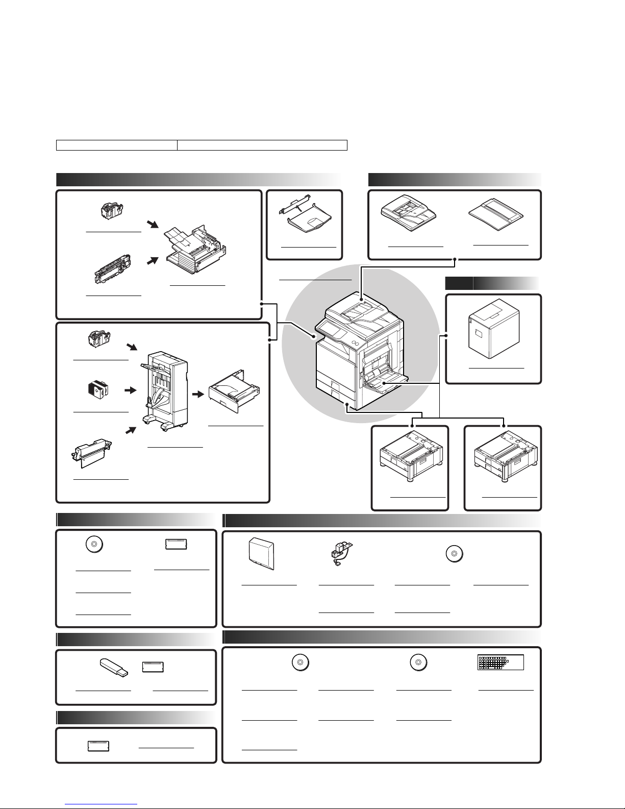
Models enable to install the unit MX-2600G/MX-2600N/MX-3100G/MX-3100N
The finisher requires a staple cartridge as a consumable part. (Staple cartridge (about 5,000 staples x 3 pcs.) MX-SCX1)
Paper exit system Document feeder system
STAPLE CARTRIDGE
12
MX-SCX1
PUNCH MODULE
10
MX-PNX1
A/B/C/D
FINISHER
7
MX-FNX9
EXIT TRAY UNIT
6
MX-TRX1
DIGITAL FULL COLOR
MULTIFUNCTIONAL SYSTEM
MX-2600N/3100N
MX-2600G/3100G
REVERSING
SINGLE PASS FEEDER
1
MX-RPX2
DOCUMENT COVER
2
MX-VRX1
Paper feed system
STAPLE CARTRIDGE
12
MX-SCX1
STAPLE CA
13
11
RTRIDGE
(For saddle)
AR-SC3
PUNCH MODULE
MX-PNX5
A/B/C/D
SADDLE STITCH
FINISHER
9
MX-FN10
Printer expansion
PRINTER
EXPANSION KIT
14
MX-PBX3
PS3 EXPANSION KIT
15
MX-PKX1
XPS EXPANSION KIT
16
MX-PUX1
BARCODE FONT KIT
17
AR-PF1
Authentication/Security
PAPER PASS UNIT
8
MX-RBX3
Image send expansion
FACSIMILE
EXPANSION KIT
18
MX-FXX2
Application/Solution
STAMP UNIT
19
AR-SU1
STAMP CARTRIDGE
20
AR-SV1
STAND/1 x 500 SHEET
PAPER DRAWER
3
MX-DEX6
INTERNET FAX
EXPANSION KIT
21
MX-FWX1
NETWORK SCANNER
EXPANSION KIT
22
MX-NSX1
LARGE CAPACITY TRAY
5
MX-LCX1
STAND/2 x 500 SHEET
PAPER DRAWER
4
MX-DEX7
APPLICATION
INTEGRATION MODULE
23
MX-AMX1
DATA SECURITY KIT
24
MX-FR10U
DATA SECURITY KIT
25
MX-FR10
Memory
EXPANSION
MEMORY BOARD
34
MX-SMX3
26
27
28
SHARPDESK
1 LICENSE KIT
MX-USX1
SHARPDESK
5 LICENSE KIT
MX-USX5
SHARPDESK
10 LICENSE KIT
MX-US10
SHARPDESK
50 LICENSE KIT
29
MX-US50
SHARPDESK
100 LICENSE KIT
30
MX-USA0
MX-FNX9 PRODUCT OUTLINE 1 – 1
APPLICATION
COMMUNICATION MODULE
31
MX-AMX2
EXTERNAL
ACCOUNT MODULE
32
MX-AMX3
33
KEYBOARD
MX-KBX1
Page 4
MX-FNX9
[2] SPECIFICTIONS
Service Manual
1. MX-FNX9
Type Inner finisher
Loading method Offset tray
Transport speed 26, 31 PPM
Tray type Offset tray
Transport reference Center reference
Paper exit direction Face down
Mode type Non-stapled, stapled
Offset quantity 30mm, 1.2 inch
Stapling 3 kinds (One position in front, one position backward, 2 positions).
Staple supply system Staple sheet cartridge replacement system (Staple cartridge (Approx. 5,000 x 3 pcs.) MX-SCX1)
Staple detection Staple empty detection (Near empty detection: 20 staples remained)
Manual stapling No
External dimensions (W x D x H) 440 x 595 x 205 (mm), 17 21/64 x 23 27/64 x 8 5/64 (inch)
Weight Approx. 13kg (28.7 lbs)
Power source Supplied from the main unit power source. (DC24V, DC5V)
Power consumption 55.2W
Installation/maintenance Installed by service personnel
Optional detection Auto detection supported
Packaged items Parts for mounting, operational sheet, staple directional instruction label, installation cautionary note
A. Allowable paper size fo paper exit/Weight
(with tray extended: 640 x 595 x 205 (mm), 25 12/64 x 23 27/64 x 8 5/64 (inch))
Allowable
paper size
Paper size 12 x 18 (A3W) Yes - -
11 x 1 7 Yes Yes 30 sheets
8.5 x 14 (216 x 356) Yes Yes 30 sheets
8.5 x 13.5 (216 x 343) Yes Yes 30 sheets
8.5 x 13.4 (216 x 340) Yes Yes 30 sheets
8.5 x 13 (216 x 330) Yes Yes 30 sheets
8.5 x 11 Yes Yes 50 sheets
8.5 x 11R Yes Yes 50 sheets
7.25 x 10.5R Yes - -
5.5 x 8.5R Yes - A3 Yes Yes 30 sheets
B4 Yes Yes 30 sheets
A4 Yes Yes 50 sheets
A4R Yes Yes 50 sheets
B5 Yes Yes 50 sheets
B5R Ye s - A5R Ye s - 8K Yes Yes 30 sheets
16K Yes Yes 50 sheets
16KR Yes - 50 sheets
Envelope *1 Yes - Custom *2 Yes - -
Paper type Thin paper 55 - 59g/m2 13 lb bond - 16 lb bond Yes Yes Yes
Plain paper 60 - 105g/m2 16 lb bond - 28 lb bond Yes Yes Yes
Recycled paper Yes Yes Yes
Colored paper Yes Yes Yes
Letterhead Yes Yes Yes
Printed paper Yes Yes Yes
punched paper Yes Yes Yes
Thick paper 106 - 209g/m2 28 lb bond -110 lb index Yes Yes *3 Yes *4
210 - 256g/m2 110 lb index - 140 lb index Yes Yes *3 Yes *4
Envelope 75 - 90g/m2 Yes - OHP Ye s - label paper Yes - Tab paper *3 Yes - Gloss paper Yes Yes User type 1 - 7 Yes Yes Yes *5
Offset
Allowable paper
quantity for stapling
*1: Supported kinds of envelopes: Monarch/Com-10/DL/C5/Long type 3/ Western type 2/ Western type 4/Long type 2
*2: Custom size support area
~
Tray (supporting soft SW) X: 182 - 432mm (7_1/
~
Manual feed X: 148 - 432mm (5_1/
217) Y: 100 - 297mm (5_1/~211_5/8)
417) Y: 132 - 297mm (5_1/~411_5/8)
*3: Thick paper (129g/m2 or above: Out of performance assurance)
MX-FNX9 SPECIFICTIONS 2 – 1
Page 5
*4: Thick paper (In the cover paper mode, allowable only 2 (in total of the front cover paper and the back cover paper) + plain paper.))
*5: Follows the paper type registration setting.
B. Allowable load quantity for each size
Function/Mode Non-offset Offset Staple
Paper size Plain paper
(60 - 105g/m2 paper)
Envelope 10*3 No No
Thin paper 500 *6 500 *6 500 *6
Thick paper 500 *6 500 *6 Cover only
gloss paper A4/8.5 x 11 500 *6 500 *6 No
Tab paper A4/8.5 x 11 100 *7 No No
Label paper A4/8.5 x 11 100 *7 No No
OHP A4/8.5 x 11 100 *7 No No
*1: 250 sheets or height of 35.5mm or less
*2: 500 sheets or height of 71mm or less
*3: Up to 10 envelopes can be loaded on the load tray.
*4: 250 sheets or 30 sets, or height of 35.5mm or less
*5: 500 sheets or 30 sets or height of 71mm or less
*6: Similarly with plain paper, the load capacity of thin paper, heavy paper, and glossy paper is limited to the earliest reach of the above number
of sheets or the limited height.
*7: 100 sheets or height of 35.5mm or less
A3W 250 *1 No No
A3 250 *1 250 *1 250 *4
B4 250 *1 250 *1 250 *4
A4 500 *2 500 *2 500 *5
A4R 500 *2 500 *2 500 *5
B5 500 *2 500 *2 500 *5
B5R 500 *2 No No
A5R 500 *2 No No
12 x 18 250 *1 No No
11 x 17 250 *1 250 *1 250 *4
8.5 x 14 250 *1 250 *1 250 *4
8.5 x 13.5 (216 x 343) 250 *1 250 *1 250 *4
8.5 x 13.4 (216 x 340) 250 *1 250 *1 250 *4
8.5 x 13 (216 x 330) 250 *1 250 *1 250 *4
8.5 x 11 500 *2 500 *2 500 *5
8.5 x 11R 500 *2 500 *2 500 *5
7.25 x 10.5R 500 *2 No No
5.5 x 8.5R 500 *2 No No
8K 250 *1 250 *1 250 *4
16K 500 *2 500 *2 500 *5
16KR 500 *2 No 500 *5
Special (Custom) 250 *1 No No
2. MX-PNX1A/B/C/D
Type Punch unit for the inner finisher
Punch type 2 holes / 3 holes / 4 holes / 4 holes (wide)
A punch unit that provides all of these 4 types can be installed.
Transport speed 23, 27, 35, 45 PPM
Transport reference Center reference
Punch dust full detection YES (Lever system)
Paper exit direction Face down
Paper weight Plain paper: 60 to 105g/m
Thin paper: 55 to 59g/m
Heavy paper: 106 to 209g/m
Punchable paper size 2 holes
(MX-PNX1A)
3 holes *1
(MX-PNX1B)
4 holes
(MX-PNX1C)
4 holes (wide)
(MX-PNX1D)
Power source Supplied from the inner finisher. (DC24V, DC5V)
External dimensions (W x D x H) 105 x 518 x 170 (mm), 4 9/64 x 20 25/64 x 6 45/64 (inch)
Weight Approx. 3.5kg (7.7 lbs)
Packaged items Parts for mounting, instructional label for punch direction, instructional label for garbage pickup, installation cautionary note
*1: Auto switching: 2 holes/3 holes
2
(16 to 28 lbs)
2
(15 to 16 lbs)
2
(28 to 56 lbs)
A3, B4, A4, A4R, B5, B5R, 11" x 17", 8.5" x 14", 8.5" x 13", 8.5" x 11", 8.5" x 11"R, 8K, 16K, 16KR
3 holes: A3, A4, 11" x 17", 8.5" x 11"
2 holes: 8.5" x 14", 8.5" x 13", 8.5" x 11"R
A3, A4
A3, B4, A4, A4R, B5, B5R, 11" x 17", 8.5" x 14", 8.5" x 13", 8.5" x 11", 8.5" x 11"R
MX-FNX9 SPECIFICTIONS 2 – 2
Page 6
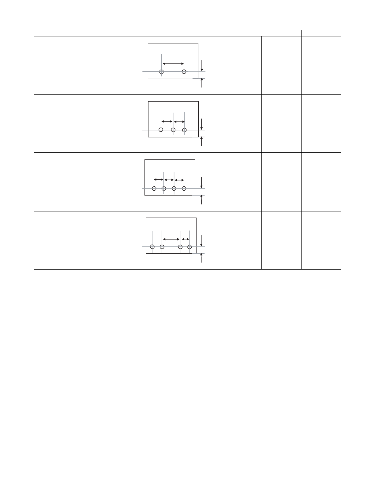
Kind of hole punch
A
A
A
A
A
A
A
Kind Hole position Hole size
2 holes (MX-PNX1A) A: 80±1mm
B: 12±3mm
B
φ6.5mm
3 holes (MX-PNX1B) A: 108±1mm
B: 12±3mm
B
4 holes (MX-PNX1C) A: 80±1mm
B: 12±3mm
B
4 holes (wide) (MX-PNX1D) A: 70±1mm
B: 12±3mm
C: 21±1mm
C
B
φ8.0mm
φ6.5mm
φ6.5mm
MX-FNX9 SPECIFICTIONS 2 – 3
Page 7
MX-FNX9
[4] EXTERNAL VIEW AND INTERNAL STRUCTURE
Service Manual
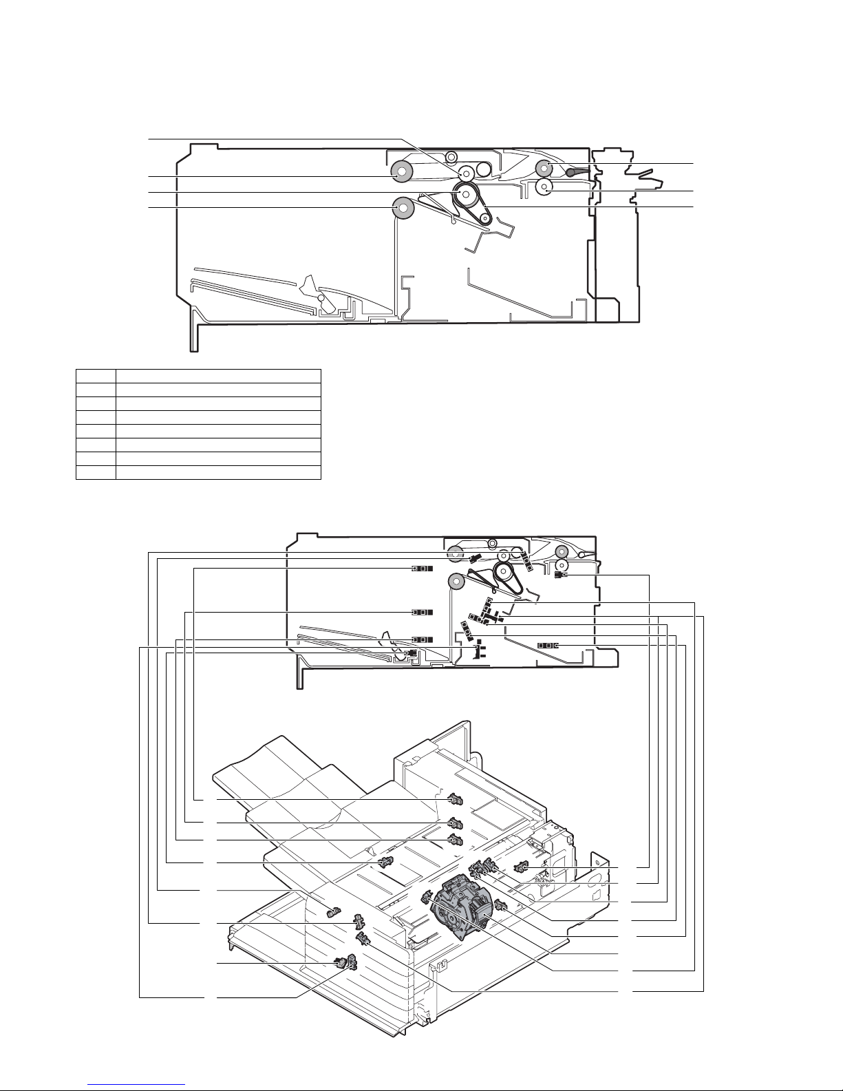
1. Identification of each section and functions
A. Internal structure
1
2
3
4
No. Name
1 Paper exit roller
2 Bundle exit paper transport roller
3 Paper exit roller
4 Bundle exit paper transport roller
5 Inlet port paper transport roller
6 Inlet port paper transport roller
7 Take-up belt
B. Sensors and switches
(1) MX-FNX9
5
6
7
1
2
3
4
12
13
14
7
MX-FNX9 EXTERNAL VIEW AND INTERNAL STRUCTURE 4 – 1
11
10
5
6
15
16,17,18
8
9
Page 8
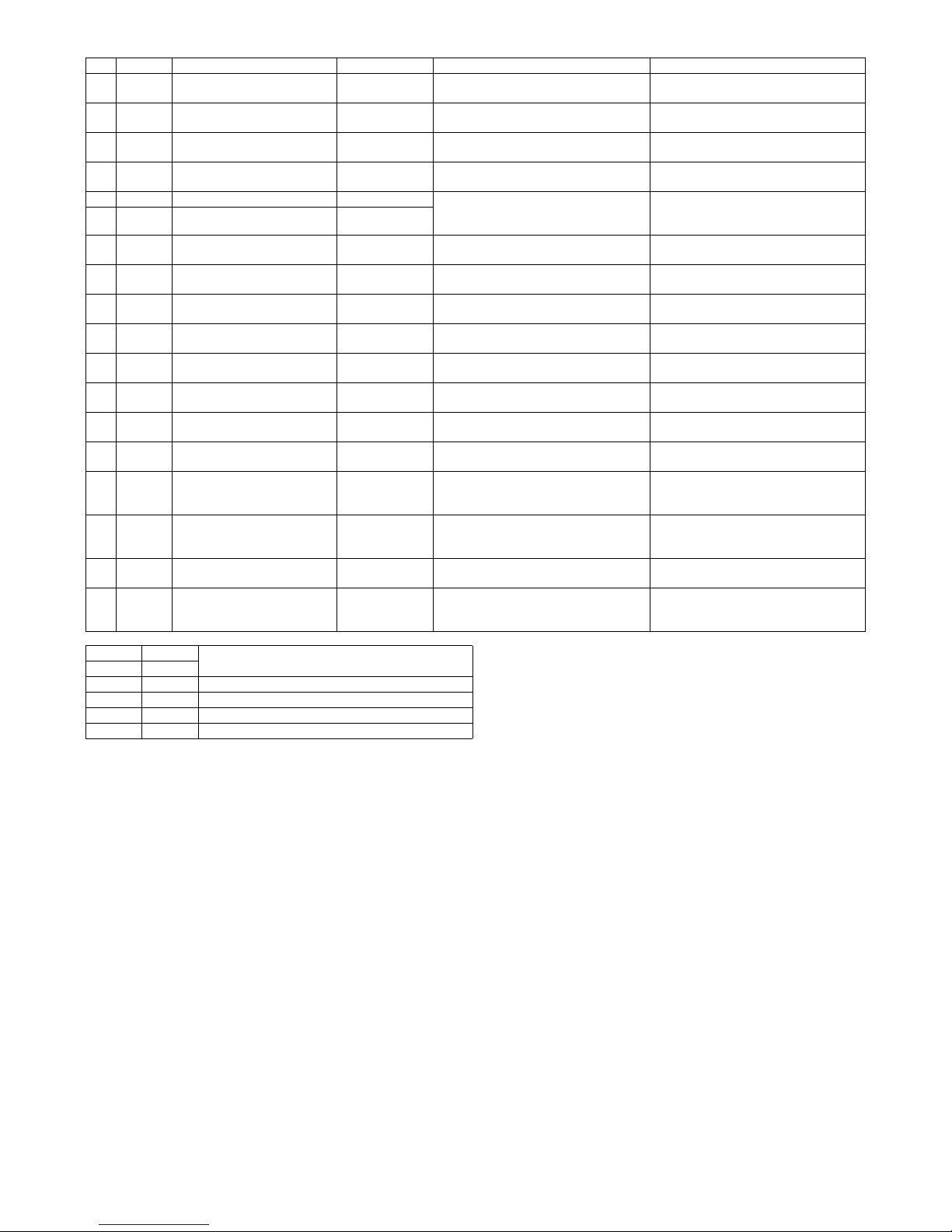
No. Signal Name Type Function/Operation Output
1 FULD Tray upper limit sensor Photo interrupter Detects the upper limit position of the
2 FMLLD Tray intermediate lower limit
sensor
3 FLLD Tray lower limit sensor Photo interrupter Detects the lower limit position of the
4 FBED Tray paper empty sensor Photo interrupter Detects paper empty in the paper load
5 FSLD1 Paper surface sensor 1 Photo interrupter Detects the surface position of paper on
6 FSLD2 Paper surface sensor 2 Photo interrupter
7 FSTHPD Stapler HP sensor Photo interrupter Detects the home position of the stapler
8 FSTPD Empty sensor Photo interrupter Detects paper empty on the process tray. TP8 is driven to “H” when paper is
9 FFJHPD Alignment plate HP sensor F Photo interrupter Detects the home position of the alignment
10 FRJHPD Alignment plate HP sensor R Photo interrupter Detects the home position of the alignment
11 FED Inlet port sensor Photo interrupter Detects paper in the inlet port of the
12 FRLD Roller up/down sensor Photo interrupter Detects the upper standby position of up/
13 FBRD Take-up belt sensor Photo interrupter Detects up/down positions of the take-up
14 FDSW Front cover switch Photo interrupter Detects open/close of the jam release
15 FJPD Alignment plate position sensor Photo interrupter Detects entry of the process section rear
16 FSHPD Stapler home sensor Detects the home position of the stapling
17 FSD Staple empty sensor Detects staple empty. (Sensor built in the
18 FSTD Self priming sensor Detects the staple feed is completed and it
Photo interrupter Detects the intermediate position of the
paper load tray up/down shift area.
paper load tray up/down shift area.
paper load tray up/down shift area.
tray.
the tray in combination of the both sensors
outputs.
unit in F/R direction shift.
guide on F side.
guide on R side.
finisher.
down movement of the bundle exit roller.
belt.
cover in the front section.
edge stopper into the opening of the
stapler and inhibits stapling.
mechanism. (Sensor built in the stapler
unit)
stapler unit)
is ready for stapling. (Sensor built in the
stapler unit)
TP1 is driven to “L” at the upper limit
position.
TP2 is driven to “L” at the intermediate
position.
TP3 is driven to “L” at the lower limit
position.
TP4 is driven to “L” when paper is
provided.
*Refer to the separate table outside the
column.
TP7 is driven to “H” at the home position.
provided.
TP9 is driven to “L” at the home position.
TP10 is driven to “L” at the home position.
TP11 is driven to “H” when paper is
provided.
TP12 is driven to “L” when the roller
reaches the upper standby position.
TP13 is driven to “L” when the take-up belt
is on the upper side.
TP15 is driven to “L” when the cover is
closed.
TP50 is driven to “L” when the stopper
enters the opening of the stapler.
TP51 is driven to “H” at the home
(standby) position.
TP53 is driven to “L” when staple empty.
TP52 is driven to “H” when in the ready
state.
FSLD1 FSLD2
TP5 TP6
“L” “H” The paper detection lever is in the save position.
“H” “H” The paper surface is upper than the reference level.
“H” “L” The paper surface is at the reference level.
“L” “L” The paper surface is lower than the reference level.
State
MX-FNX9 EXTERNAL VIEW AND INTERNAL STRUCTURE 4 – 2
Page 9
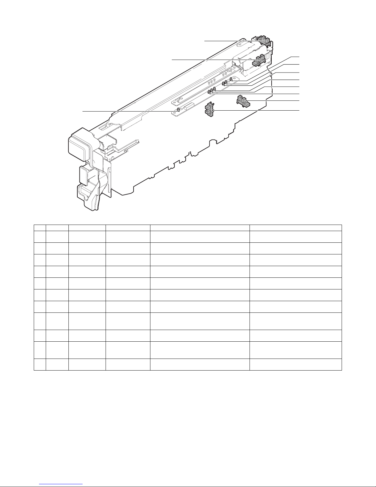
(2) MX-PNX1A/B/C/D
3
2
11
10
9
8
7
6
4
5
No. Signal Name Type Function/Operation Output
1 FPDD Full sensor Photo interrupter Detects full of the punch dust container. When full, TP2 on the punch PWB remains
2 FPHPD Punch position
sensor
3 FPRPD Rear position
sensor
4 FPSHPD Horizontal shift
HP sensor
5 FPPEND Paper rear edge
sensor
6 FPPD1 Paper horizontal
resist sensor 1
7 FPPD2 Paper horizontal
resist sensor 2
8 FPPD3 Paper horizontal
resist sensor 3
9 FPPD4 Paper horizontal
resist sensor 4
10 FPPD5 Paper horizontal
resist sensor 5
11 FPPD6 Paper horizontal
resist sensor 6
Photo interrupter Detects the home position of the punch up/down
Photo interrupter Detects the lower limit position of 3-hole side up/
Photo interrupter Detects the home position in the punch position
Transmission type
sensor
Transmission type
sensor
Transmission type
sensor
Transmission type
sensor
Transmission type
sensor
Transmission type
sensor
Transmission type
sensor
shift.
down shift in 2/3-hole punching.
horizontal resist correction mechanism.
Detects the lead edge and the rear edge of paper
to be punched.
Detects the paper edge in the rear side of B5R or
7.25" x 10" R size width direction of the machine.
Detects the paper edge in the rear side of 16K-R
size width direction of the machine.
Detects the paper edge in the rear side of 8.5"
x14", 8.5" x 11"R, 8.5" x 13", or A4R size width
direction of the machine.
Detects the paper edge in the rear side of B4 or
B5 size width direction of the machine.
Detects the paper edge in the rear side of 11" x
17", 8.5" x 11", 8K, or 16K size width direction of
the machine.
Detects the paper edge in the rear side of A3 or
A4 size width direction of the machine.
“H” level.
TP47 on the control PWB of the inner finisher
is driven to “H” at the home position.
TP48 on the control PWB of the inner finisher
is driven to “H” at the lower limit position.
TP49 on the control PWB of the inner finisher
is driven to “H” at the home position.
TP54 on the control PWB of the inner finisher
is driven to “L” when paper is provided.
TP55 on the control PWB of the inner finisher
is driven to “L” when paper is provided.
TP55 on the control PWB of the inner finisher
is driven to “L” when paper is provided.
TP55 on the control PWB of the inner finisher
is driven to “L” when paper is provided.
TP55 on the control PWB of the inner finisher
is driven to “L” when paper is provided.
TP55 on the control PWB of the inner finisher
is driven to “L” when paper is provided.
TP55 on the control PWB of the inner finisher
is driven to “L” when paper is provided.
1
MX-FNX9 EXTERNAL VIEW AND INTERNAL STRUCTURE 4 – 3
Page 10
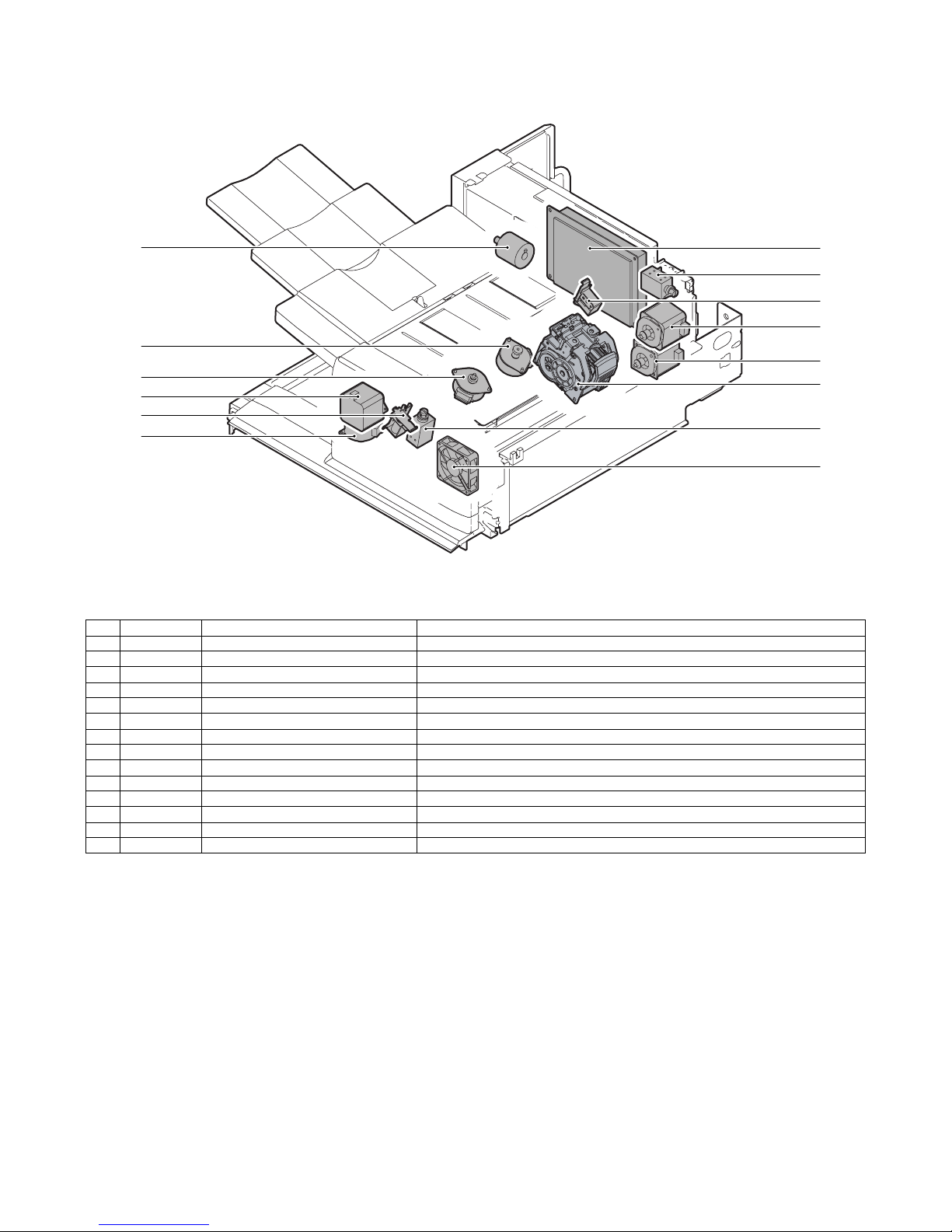
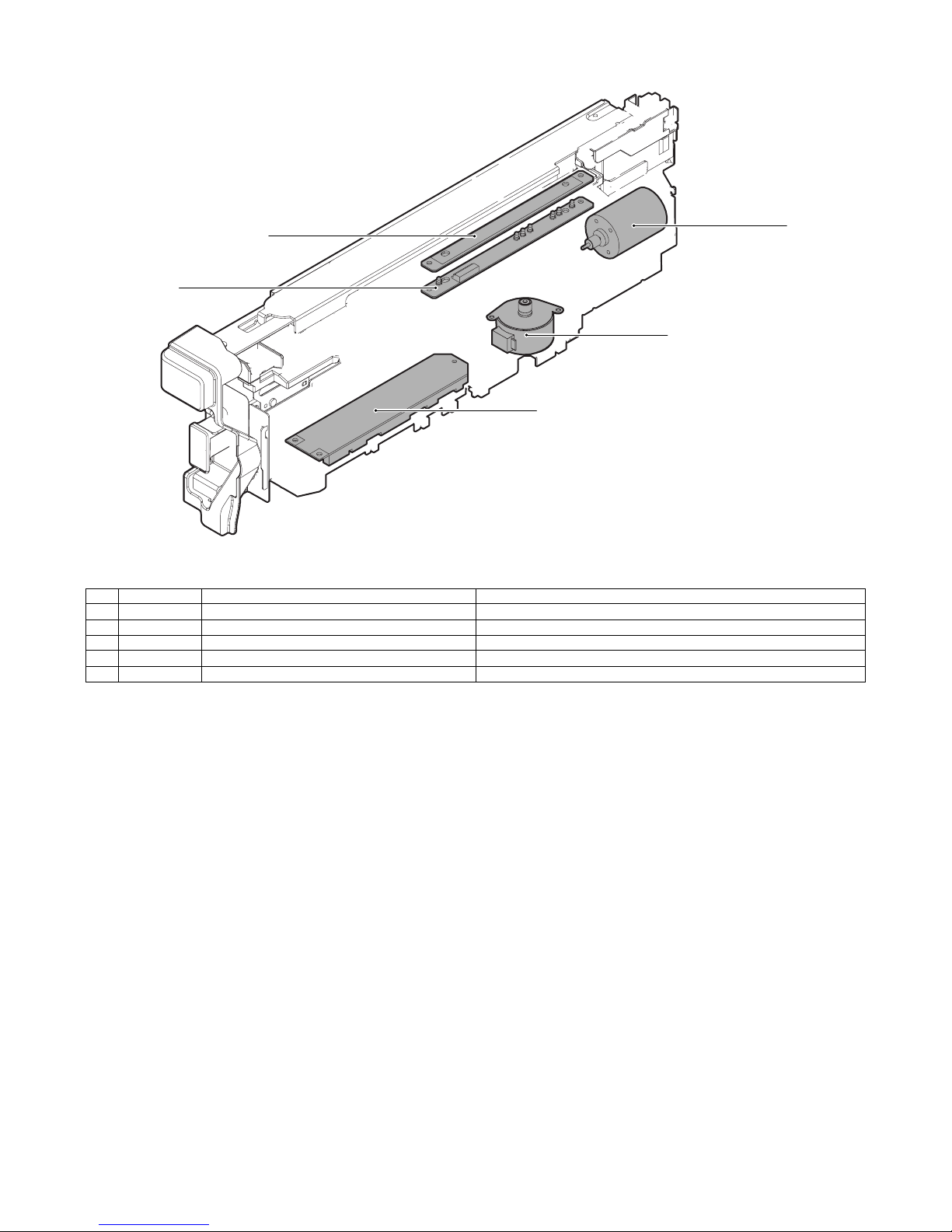
C. Motors, solenoids, and PWB
(1) MX-FNX9
3
14
12
9
8
5
7
4
6
1
11
2
10
13
No. Signal Name Function
1 FFSM Staple motor Drives the stapling mechanism. (Stapler unit built-in motor)
2 FSM Staple shift motor Shifts the stapler unit in the F/R direction.
3 FTLM Tray motor Drives the paper load tray up/down.
4 FFJM Alignment motor F Drive the alignment guide on the F side.
5 FRJM Alignment motor R Drive the alignment guide on the R side.
6 FSWM Roller upper/lower roller Drives the bundle exit roller up/down.
7 FAM Bundle exit motor Drives the bundle exit roller and the paddle.
8 FRM Transport motor Drives the inlet port roller, the feed roller, and the take-up belt.
9 FPDS Paddle one-rotation solenoid Trigger solenoid for paddle one-rotation.
10 FSLS Paper surface detection solenoid Drives the lever for paper holding and detection of the tray paper surface.
11 FBRS Belt separation solenoid Trigger solenoid for up/down shift of the take-up belt.
12 FINRPS Flapper solenoid Drives the flapper to select the entry path between the finisher inside and the reverse path.
13 FFAN Fan Cools the inlet port of the finisher.
14 – Control PWB Controls the inner finisher.
MX-FNX9 EXTERNAL VIEW AND INTERNAL STRUCTURE 4 – 4
Page 11
(2) MX-PNX1A/B/C/D
5
4
2
3
No. Signal Name Function
1 FPNM Punch motor Drives the punch unit up/down.
2 FPSM Punch horizontal resist motor Shifts the punch unit to the center of paper.
3 – Punch PWB Controls the punch unit.
4 – LED light emitting PWB Detects the paper rear edge and the punch horizontal resist.
5 – LED light receiving PWB Detects the paper rear edge and the punch horizontal resist.
1
MX-FNX9 EXTERNAL VIEW AND INTERNAL STRUCTURE 4 – 5
Page 12
MX-FNX9
[5] OPERATIONAL DESCRIPTIONS
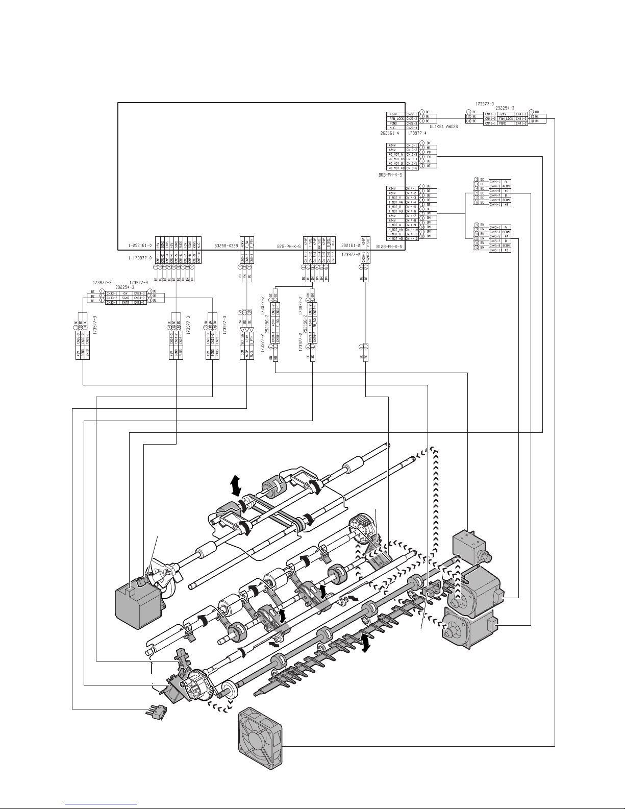
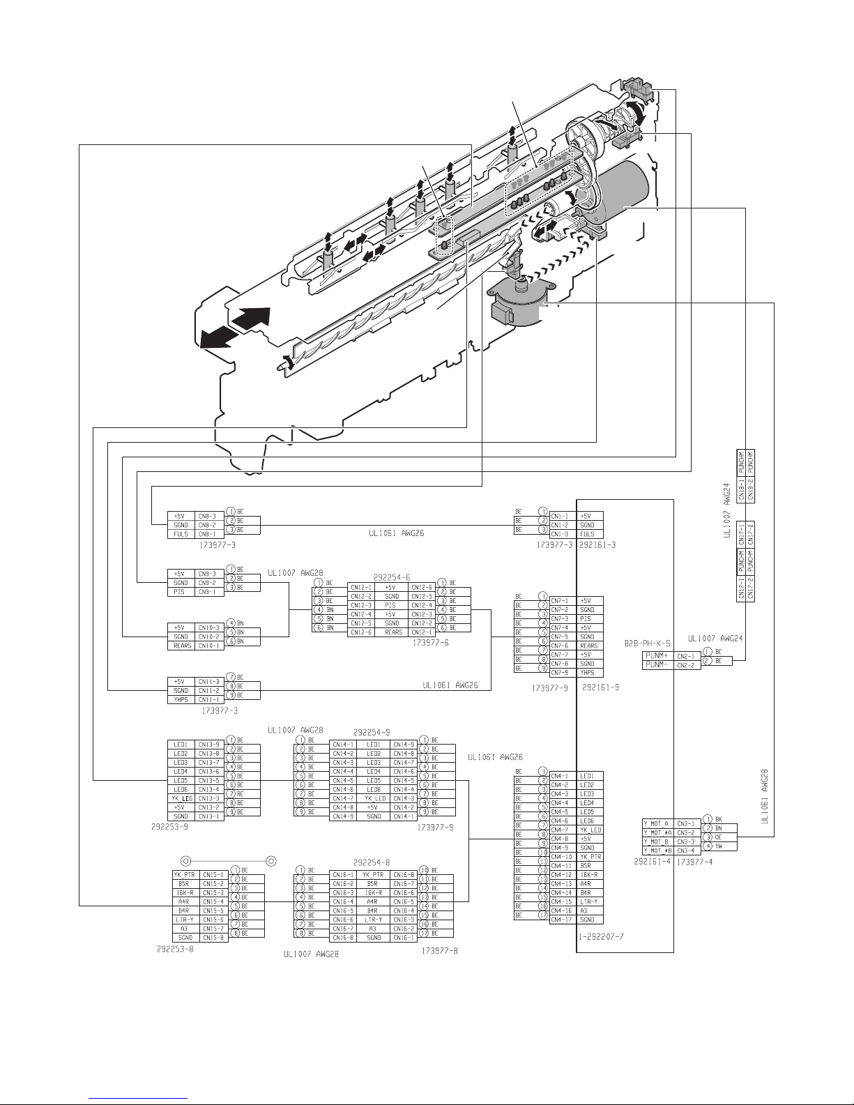
1. Electrical mechanism diagram
A. Transport, paper exit section
PCB-CONT
PF4141K200
Service Manual
FRLD
FSWM
FBRD
FBRS
FDSW
FPDS
FINRPS
FRM
FED
FAM
FFAN
MX-FNX9 OPERATIONAL DESCRIPTIONS 5 – 1
Page 13
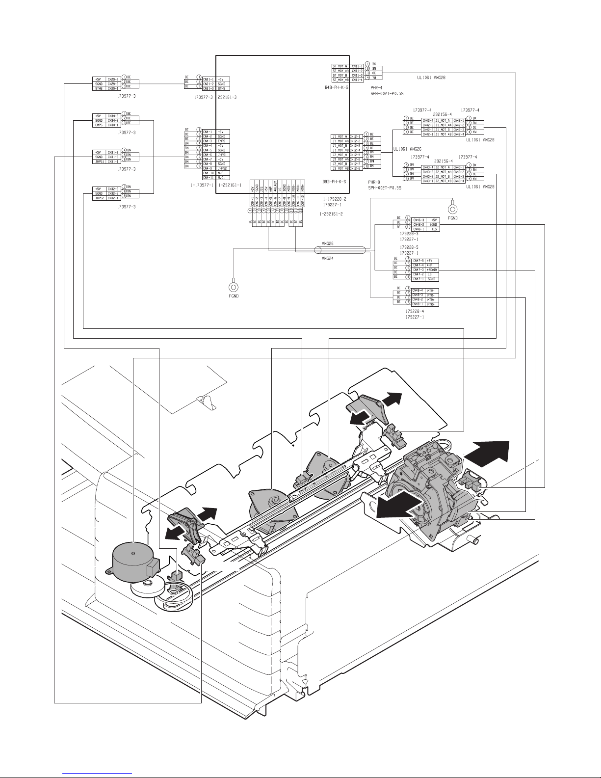
B. Staple section and aligment section
PCB-CONT
PF4141K200
FSM
FSTHPD
FFJHPD
FFJM
FSTPD
FRJHPD
FRJM
FJPD
FFSM
FSHPD(*HP)
FSD(LS)
FSTD(*READY)
MX-FNX9 OPERATIONAL DESCRIPTIONS 5 – 2
Page 14
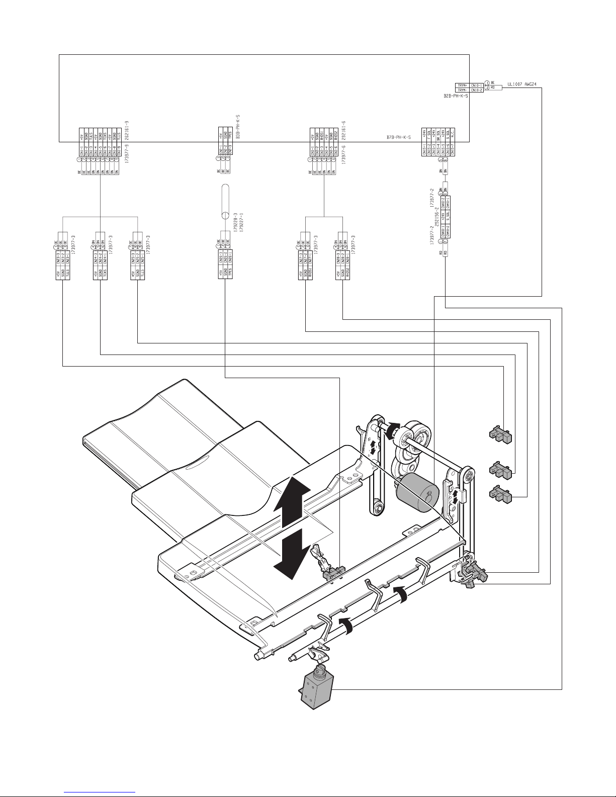
C. Paper exit tray section
PCB-CONT
PF4141K200
FBED
FSLS
FTLM
FULD
FMLLD
FLLD
FSLD1
FSLD2
MX-FNX9 OPERATIONAL DESCRIPTIONS 5 – 3
Page 15
D. Punch unit (MX-PNX1A/B/C/D)
FPPEND
FPDD
FPPD1~FPPD6
FPRPD
FPHPD
FPNM
FPSHPD
FPSM
PCB-PUNCH
YA1035K200
MX-FNX9 OPERATIONAL DESCRIPTIONS 5 – 4
Page 16
2. General
This chapter describes operations of the inner finisher. The major operation modes are as follows:
• Non-sort mode
• Offset mode
• Staple mode
• Non-sort mode + punch
• Offset mode + punch
• Staple mode + punch
In this chapter, the basic operations of the non-sort mode, the offset mode, and the staple mode are described.
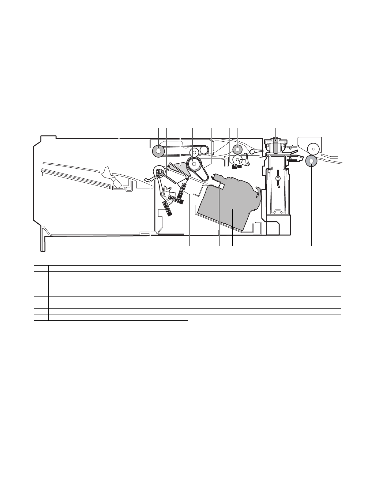
3. Outline of the transport path
The outline of the path is shown below.
1345678910
No. Name No. Name
1 Tray 9 Punch pin
2 Bundle exit roller 10 Paper rear edge sensor (FPPEND)
3 Paddle 11 Main unit paper exit roller
4 Alignment plate 12 Stapler
5 Paper exit roller 13 Paper stopper
6 Take-up belt 14 Empty sensor (FSTPD)
7 Inlet port sensor (FED) 15 Paper holding lever
8 Inlet port roller
2
1112131415
MX-FNX9 OPERATIONAL DESCRIPTIONS 5 – 5
Page 17
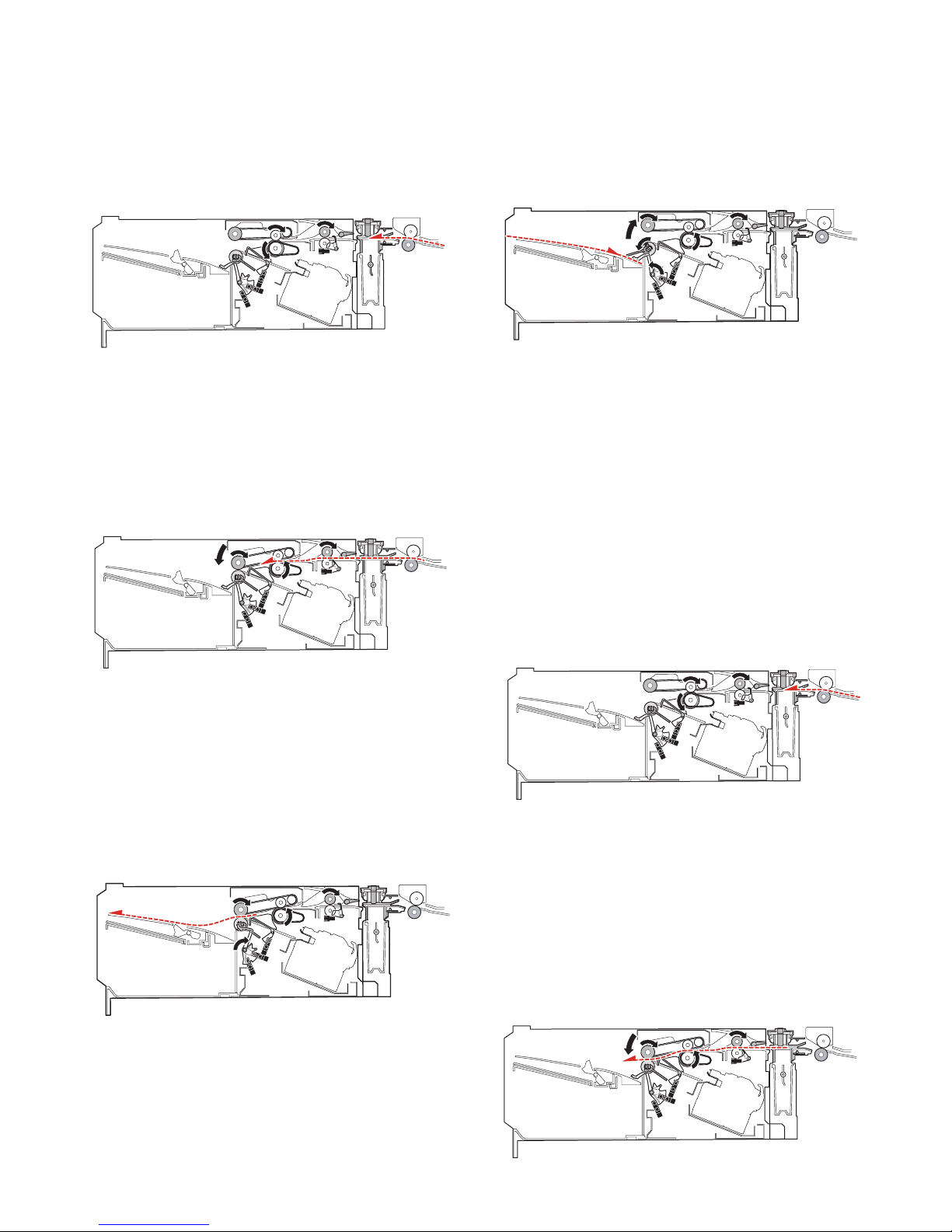
4. Non-sort mode
When the operation mode command is received from the copier,
the finisher makes the finisher operation status command the JOB
and starts the transport operation.
A. Reception of paper discharged from the main
unit
1) The transport motor (FRM) is driven at the paper exit speed of
the main unit to receive paper from the main unit.
2) Immediately after the paper rear edge passes the bundle exit
roller, the paddle one-rotation solenoid (FPDS) is turned ON to
take-up the paper falling onto the tray.
3) When paper is transported by 10mm after the paper rear edge
passes the bundle exit roller, the bundle exit motor (FAM) is
accelerated to 200mm/sec. Just before the paddle passes the
load tray, the paper surface detection solenoid (FSLS) is
turned ON to hold the paper discharged by the paper holding
lever.
2) After turning ON the inlet port sensor (FED), the roller up/down
motor (FSWM) is driven to lower the bundle exit roller. The
bundle exit motor (FAM) is driven at the paper exit speed of
the main unit to drive the bundle exit roller. When the paper
width is 210mm or more, the alignment motor F (FFJM) and
the alignment motor R (FRJM) are driven by turning ON the
inlet port sensor (FED) to shift the alignment plate to 15mm
inside the paper and put it under the paper.
3) In the case of the punch mode, punching is performed as
described in "7. Punching process."
B. Paper exit
1) After the paper rear edge passes the paper exit roller of the
main unit, the transport motor (FRM) and the bundle exit motor
(FAM) are accelerated to 480mm/sec. When the paper rear
edge passes the inlet port sensor (FED) and then transport of
a certain amount is made, the alignment plate is shifted to the
home position.
Before the paper rear edge passes the bundle exit roller, the
paper surface detection solenoid (FSLS) is turned OFF and
the bundle exit roller speed is decelerated to 100mm/sec at the
same time, performing paper exit deceleration of paper.
4) When the paddle rotates one turn, the bundle exit motor (FAM)
is stopped.
5) When there is next paper, repeat the procedures from "A-1)."
6) When there is no next paper, the actuators are turned OFF
and the finisher operation status command is set to READY,
and the transport operation is terminated.
5. Offset mode
When the operation mode command is received from the copier,
the finisher makes the finisher operation status command the JOB
and starts the transport operation.
A. Reception of paper discharged from the main
unit
1) The transport motor (FRM) is driven at the paper exit speed of
the main unit to receive paper from the main unit. When the
paper length is 216mm or less, the paper exit speed of the second and later sheets from the main unit is 280mm/sec.
B. Paper take-up and alignment
1) For the first sheet of a bundle, the inlet port sensor (FED) is
turned ON and the roller up/down motor (FSWM) is driven to
lower the bundle exit roller. The bundle exit motor (FAM) is
driven at the paper exit speed of the main unit to drive the bundle exit roller.
In addition, the alignment motor F (FFJM) and the alignment
motor R (FRJM) are driven by turning ON the inlet port sensor
(FED) to shift the alignment plate to 15mm outside the paper,
and enter the standby state. After transport of a certain
amount, the roller up/down motor (FSWM) is driven to lift the
bundle exit roller, stopping the bundle exit motor (FAM).
MX-FNX9 OPERATIONAL DESCRIPTIONS 5 – 6
Page 18

2) For the second and later sheets of a bundle, the inlet port sensor (FED) turns ON and a certain amount is transported, and
then the alignment motor F (FFJM) and the alignment motor R
(FRJM) are driven to shift the alignment plate to 15mm outside
the paper and to put it under the standby state.
3) After the paper rear edge passes the paper exit roller of the
main unit, the transport motor (FRM) is accelerated to 480mm/
sec.
4) In the punch mode, punching is performed as described in "7.
Punching process."
5) When the paper rear edge passes the inlet port sensor (FED)
and a certain amount is transported, the roller up/down motor
(FSWM) is driven to lower the bundle exit roller and the bundle
exit motor (FAM) is driven for a certain amount in the take-up
direction at the paper exit speed of the main unit to take up
paper to the process tray. In addition, the belt separation solenoid (FBRS) is turned ON to lower the take-up belt.
6) After completion of take-up, the roller up/down motor (FSWM)
is driven to lift the bundle exit roller. The alignment motor F
(FFJM) and the alignment motor R (FRJM) are driven for a certain amount to align paper in the process tray. If there are two
or more sheets to be aligned, the procedures are repeated
from "A-1)" for the specified number of sheets. However, the
paper exit operation of "C. Aligned paper exit" is performed for
every 3 sheets.
2) After transport of paper by a certain amount, the alignment
motor F (FFJM) and the alignment motor R (FRJM) are driven
to shift the alignment plate to the home position.
3) When the paper rear edge passes the empty sensor (FSTPD),
the paper surface detection solenoid (FSLS) is turned OFF
and the bundle exit roller speed is decelerated to 100mm/sec
at the same time, decelerating the paper exit operation.
4) Immediately after the paper rear edge passes the bundle exit
roller, the paddle one-rotation solenoid (FPDS) is turned ON to
take up paper falling onto the tray.
5) When the paper rear edge passes the bundle exit roller and
the paper is transported for 10mm, the bundle exit motor
(FAM) is accelerated to 200mm/sec. Before the paddle passes
the load tray, the paper surface detection solenoid (FSLS) is
turned ON to hold the discharged paper with the paper holding
lever.
C. Aligned paper exit
1) After completion of alignment, the belt separation solenoid
(FBRS) is turned ON to lift the take-up belt. The alignment
motor F (FFJM) and the alignment motor R (FRJM) are driven
to separate paper from the alignment plate by 1mm. In addition, the roller up/down motor (FSWM) is driven to lower the
bundle exit roller. The bundle exit motor (FAM) is started at the
speed of 450mm/sec and paper in the process tray is discharged.
6) When the paddle rotates one turn, the bundle exit motor (FAM)
is stopped.
7) When there is next paper, the procedures are repeated from
"A-1)."
8) When there is no next paper, the actuators are turned OFF and
the finisher operation status command is set to READY to terminate the transport operation.
6. Staple mode
When the operation mode command is received from the copier,
the finisher makes the finisher operation status command the JOB
and starts the transport operation.
A. Reception of paper discharged from the main
unit
1) The transport motor (FRM) is driven at the paper exit speed of
the main unit to receive paper from the main unit. When the
paper length is 216mm or less, the paper exit speed of the second and later sheets from the main unit is 280mm/sec.
MX-FNX9 OPERATIONAL DESCRIPTIONS 5 – 7
Page 19

B. Paper take-up, alignment and staple
1) For the first sheet of a bundle, after turning on the inlet sensor
(FED), the roller up/down motor (FSWM) is driven to lower the
bundle exit roller. The bundle exit motor (FAM) is driven at the
paper exit speed of the main unit to drive the bundle exit roller.
By turning on the inlet port sensor (FED), the alignment motor
F (FFJM) and the alignment motor R (FRJM) are driven to shift
the alignment plate to 15mm outside the paper and to put it
under the standby state. After transport of a certain amount,
the roller up/down motor (FSWM) is driven to lift the bundle
exit roller to terminate the bundle exit motor (FAM).
2) For the second and later sheets, after transporting paper from
the inlet port sensor (FED) by a certain amount, the alignment
motor F (FFJM) and the alignment motor R (FRJM) are driven
to shift the alignment plate to 15mm outside the paper and to
put it under the standby state.
3) For the last sheet of a bundle, the inlet port sensor (FED) is
turned ON to drive the staple shift motor (FSM) to shift the stapler to the binding position.
4) After the paper rear edge passed the paper exit roller of the
main unit, the transport motor (FRM) is accelerated to 480mm/
sec.
5) In the punch mode, punching is performed as described in "7.
Punching process."
6) When the paper rear edge passes the inlet port sensor (FED)
and paper is transported by a certain amount, the roller up/
down motor (FSWM) is driven to lower the bundle roller and
the bundle exit motor (FAM) is driven in the take-up direction at
the paper exit speed of the main unit by a certain amount to
take up paper to the process tray. In addition, the belt separation solenoid (FBRS) is turned ON to lower the take-up belt.
8) After completion of alignment of a specified number of sheets,
the staple motor (FFSM) is started to staple at the specified
position.
C. Aligned and stapled paper exit
1) After completion of stapling, the belt separation solenoid
(FBRS) is turned ON to lift the take-up belt. The alignment
motor F (FFJM) and the alignment motor R (FRJM) are driven
to shift the alignment plate by 1mm from paper. Then the roller
up/down motor (FSWM) is driven to lower the bundle exit roller
to press, and the bundle exit motor (FAM) is started at 450mm/
sec to discharge paper from the process tray.
2) After transporting paper by a certain amount, the alignment
motor F (FFJM) and the alignment motor R (FRJM) are driven
to shift the alignment plate to the home position.
3) After the paper rear edge passes the empty sensor (FSTPD),
the paper surface detection solenoid (FSLS) is turned OFF
and the bundle exit roller speed is decelerated to 100mm/sec
at the same time to decelerate paper exit of the paper bundle.
At the same time, the roller up/down motor (FSWM) is driven in
the lifting direction to decrease the pressure of the bundle
roller. In addition, the tray motor (FTLM) is driven to lower the
load tray by 5mm.
7) After completion of take-up, the roller up/down motor (FSWM)
is driven to lift the bundle exit roller. The alignment motor F
(FFJM) and the alignment motor R (FRJM) are driven by a certain amount to align paper in the process tray. If there are two
or more sheets to be aligned, the operation is repeated from
"A-1)."
4) Immediately after the paper rear edge passes the bundle exit
roller, the paddle one-rotation solenoid (FPDS) is turned ON to
take up roller falling onto the tray.
5) When paper is transported by 10mm after the paper rear edge
passes the bundle exit roller, the bundle exit motor (FAM) is
decelerated to 200mm/sec.
MX-FNX9 OPERATIONAL DESCRIPTIONS 5 – 8
Page 20

6) When the paddle rotates one turn, the bundle exit motor (FAM)
is stopped.
7) After the paddle rotates one turn, the paper surface detection
solenoid (FSLS) is turned ON for 100msec and then OFF.
Then it is turned ON after 400msec. At that time, if the paper
surface level is lower than the reference level, the tray motor
(FTLM) is driven to lift the load tray to the reference level.
8) If there is next paper, the operation is repeated from "A-1)."
9) If there is no next paper, the actuators are turned OFF and the
finisher operation status command is set to READY state, and
the transport operation is terminated.
7. Punching process
When the operation mode command is received from the copier,
the finisher makes the finisher operation status command the JOB
and starts the transport operation.
A. Reception of paper discharged from the main
unit
1) The transport motor (FRM) is driven at the paper exit speed of
the main unit to receive paper from the main unit. When the
paper length is 216mm or less in the offset mode or in the staple mode, the paper exit speed of the second and later sheets
of the same bundle from the main unit is 280mm/sec.
C. Punching process 2
1) After completion of punching, the transport motor (FRM) and
the bundle exit motor (FAM) are driven to transport paper and
the specified after-process is executed. The motor speed is
300mm/sec for the non-sort mode, and 480mm/sec for the offset mode or the staple mode.
B. Punching process 1
1) When the paper rear edge passes the paper rear edge sensor,
the transport motor (FRM) is stopped and paper transport is
stopped.
2) When the paper is stopped, the punch motor (FPNM) is driven
to punch at the paper rear edge.
MX-FNX9 OPERATIONAL DESCRIPTIONS 5 – 9
Page 21

MX-FNX9
[6] DISASSEMBLY AND
ASSEMBLY
1. MX-FNX9
A. Exterior
(1) Inner finisher
1) Loosen the screw, and disconnect the connector from the main
unit.
2) Open the front cover, and remove the punch unit cover.
Service Manual
(2) Inner cover
1) Remove the inner finisher from the main unit. Refer to A-(1).
2) Remove the inner cover.
1
3) Remove the stopper.
4) Remove the screw, and remove the rail stay.
2
(3) Rear cover
1) Remove the inner finisher from the main unit. Refer to A-(1).
2) Slide the rail, and remove the rear cover.
2
1
(4) Left cover, bottom cover
1) Remove the inner finisher from the main unit. Refer to A-(1).
2) Remove the left cover and the bottom cover.
5) Remove the inner finisher from the main unit.
1
2
MX-FNX9 DISASSEMBLY AND ASSEMBLY 6 – 1
Page 22

(5) Reverse guide unit
1) Remove the inner finisher from the main unit. Refer to A-(1).
2) Remove the inner cover. Refer to A-(2).
3) Remove the reverse guide unit.
B. Transport section, paper exit section
(1) Paddle
1) Open the front cover, and slide the inner finisher.
2
(2) Flapper solenoid
1) Remove the inner finisher from the main unit. Refer to A-(1).
2) Disconnect the connector, and remove the flapper solenoid.
* When installing, shift and fix the solenoid so that the reverse
flapper and the cushion material are in contact with each
other with the solenoid plunger pushed in.
1
2) Remove the paddle holders, and remove the paddles.
(3) Inlet port sensor
1) Remove the inner finisher from the main unit. Refer to A-(1).
2) Remove the sensor holder, and remove the inlet port sensor.
MX-FNX9 DISASSEMBLY AND ASSEMBLY 6 – 2
Page 23

(4) Roller up/down sensor
1) Remove the inner finisher from the main unit. Refer to A-(1).
2) Remove the inner cover. Refer to A-(2).
3) Remove the bracket, and remove the roller up/down sensor.
(5) Take-up belt sensor
1) Remove the inner finisher from the main unit. Refer to A-(1).
2) Remove the inner cover. Refer to A-(2).
3) Slide the harness guide, remove the bracket, and remove the
take-up belt sensor.
2
(7) Belt separation solenoid
1) Remove the inner finisher from the main unit. Refer to A-(1).
2) Remove the inner cover. Refer to A-(2).
3) Remove the reverse guide unit. Refer to A-(5).
4) Remove the parts, and remove the belt separation solenoid.
2
3
1
(8) Bundle exit paper transport roller
1) Remove the inner finisher from the main unit. Refer to A-(1).
2) Remove the inner cover. Refer to A-(2).
3) Remove the reverse guide unit. Refer to A-(5).
4) Remove the parts, and remove the bundle exit paper transport
roller unit.
1
(6) Roller up/down motor
1) Remove the inner finisher from the main unit. Refer to A-(1).
2) Remove the inner cover. Refer to A-(2).
3) Remove the rear cover. Refer to A-(3).
4) Remove the reverse guide unit.
5) Slide the stapler drive unit. Disconnect the connector from the
PWB. Remove the roller up/down motor unit. Remove the
roller up/down motor.
1
3
2
3
2
1
2
5) Remove the parts, and remove the bundle exit paper transport
roller.
3
1
2
1
MX-FNX9 DISASSEMBLY AND ASSEMBLY 6 – 3
Page 24

(9) Take-up belt, paper exit roller
1) Remove the inner finisher from the main unit. Refer to A-(1).
2) Remove the inner cover. Refer to A-(2).
3) Remove the reverse guide unit. Refer to A-(5).
4) Remove the parts, and remove the bundle roller up/down lever
unit.
7) Remove the parts, and remove the take-up belt and the paper
exit roller.
3
1
2
1
1
5) Remove the parts, and remove the bundle roller unit.
2
1
1
6) Remove the parts, and pull out the belt unit. Remove the parts,
and remove the belt unit.
3
1
2
2
2
3
1
(10) Inlet port gate
1) Remove the inner finisher from the main unit. Refer to A-(1).
2) Remove the inner cover. Refer to A-(2).
3) Remove the left cover and the bottom cover. Refer to A-(4).
4) Remove the reverse guide unit. Refer to A-(5).
5) Remove the PWB. Refer to F-(1).
6) Remove the flapper solenoid. Refer to B-(2).
7) Remove the slide rail. Remove the slider fixing bracket and
remove the earth terminal.
3
2
1
2
MX-FNX9 DISASSEMBLY AND ASSEMBLY 6 – 4
Page 25

8) Remove the tray unit.
9) Remove the harness from the guide, and remove the bottom
plate.
(11) Inlet port paper transport roller
1) Remove the inner finisher from the main unit. Refer to A-(1).
2) Remove the inner cover. Refer to A-(2).
3) Remove the tray unit. Refer to B-(10).
4) Remove the bottom plate. Refer to B-(10).
5) Remove the inlet port upper guide, and remove the transport
guide.
6) Remove the parts, and remove the inlet port paper transport
roller.
10) Remove the inlet port upper guide.
11) Remove the spring, and remove the parts. Remove the inlet
port gate.
2
3
4
1
1
2
3
2
(12) Transport motor
1) Remove the inner finisher from the main unit. Refer to A-(1).
2) Remove the inner cover. Refer to A-(2).
3) Remove the tray unit. Refer to B-(10).
4) Remove the bottom plate. Refer to B-(10).
5) Disconnect the connector, and remove the transport motor.
1
3
1
2
MX-FNX9 DISASSEMBLY AND ASSEMBLY 6 – 5
Page 26

(13) Bundle exit motor
1) Remove the inner finisher from the main unit. Refer to A-(1).
2) Remove the inner cover. Refer to A-(2).
3) Remove the tray unit. Refer to B-(10).
4) Remove the bottom plate. Refer to B-(10).
5) Disconnect the connector, and remove the bundle exit motor.
5) Remove the bundle exit paper transport unit.
1
1
1
1
3
2
(14) Paddle one-rotation solenoid
1) Remove the inner finisher from the main unit. Refer to A-(1).
2) Remove the inner cover. Refer to A-(2).
3) Remove the tray unit. Refer to B-(10).
4) Remove the bottom plate. Refer to B-(10).
5) Remove the paddle one-rotation solenoid.
2
6) Remove each parts, and remove the sensor lever.
7) Remove the center weight, and remove the process tray unit.
1
C. Process tray section
(1) Alignment motors F and R
1) Remove the inner finisher from the main unit. Refer to A-(1).
2) Remove the inner cover. Refer to A-(2).
3) Remove the tray unit. Refer to B-(10).
4) Remove the load cover. Refer to B-(10).
2
MX-FNX9 DISASSEMBLY AND ASSEMBLY 6 – 6
Page 27

8) Remove the alignment plate. Remove the screws and the
pawl, and remove the process tray.
1
2
D. Staple section
(1) Staple cartridge
1) Open the front cover, and slide the inner finisher. Refer to B(1).
2) Release the lock, and remove the staple cartridge.
(2) Staple unit
1) Remove the inner finisher from the main unit. Refer to A-(1).
2) Remove the inner cover. Refer to A-(2).
3) Remove the latch cover. Remove the parts and the shaft.
9) Slide the unit and remove the alignment motors F and R.
(2) Empty sensor, alignment plate HP sensors F and R
1) Remove the inner finisher from the main unit. Refer to A-(1).
2) Remove the inner cover. Refer to A-(2).
3) Remove the tray unit. Refer to B-(10).
4) Remove the process tray unit. Refer to C-(1).
5) Remove the bracket and the empty sensor. Remove the alignment plate HP sensors F and R.
1
2
4) Remove the screw from the bottom. Remove the staple unit,
and disconnect the connector.
5
4
3
1
2
MX-FNX9 DISASSEMBLY AND ASSEMBLY 6 – 7
Page 28

(3) Alignment plate position sensor
1) Remove the inner finisher from the main unit. Refer to A-(1).
2) Shift the staple unit to the front side.
3) Remove the bracket and remove the position sensor.
7) Disconnect the connector from the PWB, and remove the staple shift motor.
(5) Stapler HP sensor
1) Remove the inner finisher from the main unit. Refer to A-(1).
2) Remove the inner cover. Refer to A-(2).
3) Put the inner finisher upside down, and remove the stapler HP
sensor.
(4) Staple shift motor
1) Remove the inner finisher from the main unit. Refer to A-(1).
2) Remove the inner cover. Refer to A-(2).
3) Remove the rear cover. Refer to A-(3).
4) Remove the reverse guide unit. Refer to A-(5).
5) Remove the roller up/down motor. Refer to B-(6).
6) Remove the E-ring, the flange and the gear pulley, and remove
the gear.
E. Paper exit tray section
(1) Paper surface sensors 1, 2
1) Remove the inner finisher from the main unit. Refer to A-(1).
2) Remove the inner cover. Refer to A-(2).
3) Remove the tray unit. Refer to B-(10).
4) Remove the load cover. Refer to C-(1).
5) Remove the parts, and remove the sensor lever.
MX-FNX9 DISASSEMBLY AND ASSEMBLY 6 – 8
Page 29

6) Remove the bracket, and remove the paper surface sensors 1,
2.
(2) Paper surface detection solenoid
1) Remove the inner finisher from the main unit. Refer to A-(1).
2) Remove the inner cover. Refer to A-(2).
3) Remove the tray unit. Refer to B-(10).
4) Remove the bundle exit paper transport roller unit, the sensor
lever, the process tray unit. Refer to C-(1).
5) Remove the paper surface detection solenoid unit, and
remove the paper surface detection solenoid.
(3) Tray upper limit sensor, tray intermediate lower
limit sensor, tray lower limit sensor
1) Remove the inner finisher from the main unit. Refer to A-(1).
2) Remove the tray unit. Refer to B-(10).
3) Remove the harness guide, and remove the tray upper limit
sensor, the tray intermediate lower limit sensor, and the tray
lower limit sensor.
(4) Tray motor
1) Remove the inner finisher from the main unit. Refer to A-(1).
2) Remove the tray unit. Refer to B-(10).
3) Remove the tray left bracket and the tray drive unit.
4) Remove the tray drive unit.
MX-FNX9 DISASSEMBLY AND ASSEMBLY 6 – 9
Page 30

5) Remove the gear, and remove the tray motor.
2
1
(5) Tray paper empty sensor
1) Remove the inner finisher from the main unit. Refer to A-(1).
2) Remove the left cover and the bottom cover. Refer to A-(4).
3) Remove the tray bottom cover.
F. O th er s
(1) Control PWB
1) Remove the inner finisher from the main unit. Refer to A-(1).
2) Remove the rear cover. Refer to A-(3).
3) Disconnect the connector, and remove the screw. Remove the
PWB support and remove the control PWB.
3
3
2
2
3
2
4) Pull out the tray. Remove the screw, and remove the tray.
1
(2) Fan
1) Remove the inner finisher from the main unit. Refer to A-(1).
2) Shift the staple unit to the rear side. Disconnect the connector
and remove the fan.
* When installing, take care that the label of the fan comes to
the direction illustrated.
(3) Front cover switch
1) Remove the inner finisher from the main unit. Refer to A-(1).
2) Remove the inner cover. Refer to A-(2).
3) Remove the spring, and remove the interlock sensor lever.
Remove the front cover switch, and disconnect the connector.
5) Remove the tray paper empty sensor.
Yellow
Red
Blue
3
MX-FNX9 DISASSEMBLY AND ASSEMBLY 6 – 10
1
2
4
Page 31

2. MX-PNX1A/B/C/D
A. Punch unit (MX-PNX1A/B/C/D)
(1) Punch unit (MX-PNX1A/B/C/D)
1) Remove the coin screw, and remove the finisher slide stopper.
2) Open the front cover, and slide the inner finisher.
2
1
5) Remove the punch unit from the main unit.
(2) LED light receiving PWB
1) Remove the punch unit. Refer to A-(1).
2) Remove the PWB holder, and remove the LED light receiving
PWB.
3) Remove the dust box.
4) Remove the punch cover.
(3) Punch horizontal resist motor
1) Remove the punch unit. Refer to A-(1).
2) Remove the guide cover. Disconnect the connector, and
remove the harness guide.
2
2
1
3
MX-FNX9 DISASSEMBLY AND ASSEMBLY 6 – 11
Page 32

3) Remove the punch horizontal resist motor.
1
2
3) Fit the gear hole with the screw position, and remove the
screw. Remove the punch motor.
(4) Punch PWB
1) Remove the punch unit. Refer to A-(1).
2) Remove the guide cover and the harness guide. Refer to A(3).
3) Remove the punch PWB.
(5) Punch motor
1) Remove the punch unit. Refer to A-(1).
2) Disconnect the connector, and remove the link plate. Remove
the spring, and separate the upper unit and the lower unit.
1
(6) LED light emitting PWB
1) Remove the punch unit. Refer to A-(1).
2) Remove the lower unit. Refer to A-(5).
3) Remove the roller and the PWB holder. Remove the LED light
emitting PWB.
3
2
1
(7) Rear position sensor
1) Remove the punch unit. Refer to A-(1).
2) Remove the rear position sensor.
4
5
4
4
3
2
MX-FNX9 DISASSEMBLY AND ASSEMBLY 6 – 12
Page 33

(8) Punch position sensor
1) Remove the punch unit. Refer to A-(1).
2) Remove the upper unit. Refer to A-(5).
3) Remove the harness guide.
4) Remove the punch position sensor.
4) Remove the screws and the pawl, and lift up the harness
guide. Disconnect the connector, and remove the horizontal
shift HP sensor.
3
1
2
(9) Horizontal shift HP sensor
1) Remove the punch unit. Refer to A-(1).
2) Remove the guide cover and the harness guide. Refer to A(3).
3) Disconnect the connector, and remove the harness.
(10) Full sensor
1) Remove the punch unit. Refer to A-(1).
2) Remove the drive bracket, and remove the full sensor.
MX-FNX9 DISASSEMBLY AND ASSEMBLY 6 – 13
Page 34

MX-FNX9
[7] MAINTENANCE
Service Manual
1. Maintenance system table
: Check (Clean, replace, or adjust according to the necessity.) {: Clean : Replace : Adjust ✩: Lubricate : Shift position
No. Part name When calling
Follows the main unit
cycle.
Remark
1 Transport rollers {
2 Transport paper guides {
3Gears When chacking, apply to the necessary positions. (Specified positions)
4Belts
5 Knurling belt { Replacement reference: Finisher count value of 1000K.
6 Paddle {
7Sensors
8 Discharge brush
9 Stapler unit Replacement reference: Replace the unit for every
200K stapling.
10 Punch unit Replacement reference: Replace the unit for every
1000K punching.
11 Staple cartridge User replacement for every use of 5,000 pcs.
1
1
1
1
1
1
7
7
7
7
7
7
7
7
7
8
6
6
6
8
6
8
6
6
5
7
7
7
7
7
7
7
7
7
7
7
7
10
5
9
11
MX-FNX9 MAINTENANCE 7 – 1
Page 35

MX-FNX9
[8] ADJUSTMENTS
Each adjustment item in the adjustment item list is identified with its
own JOB No. The adjustments are basically executed in the
sequence from a smaller JOB No. to a larger JOB No.
There is, however, no need to perform all the adjustment items.
Only the necessary items may be executed depending on the situation.
Unnecessary items may be skipped to go to the next necessary
item. In this case, of course, the adjustment sequence could be
executed from a smaller to a larger JOB No.
If the above is neglected, the adjustment cannot be completed normally, resulting in a trouble.
[Start of simulation]
1) Press [COPY MODE] key to enter the copy mode.
2) Press [P] (Program) key → [*] (Asterisk) key → [C] (Clear) key
→ [*] (Asterisk) key in this sequence.
3) The display is shifted to the simulation main number entry
screen (entry standby screen).
1. Setting item list
JOB No. Adjustment item list
1 Punch unit, punch PWB destination setting –
2 Finisher adjustment 3-10
3 Flapper solenoid adjustment –
4 Punch home position adjustment –
Simulation
to be used
2. Details
ADJ 1 Punch unit, punch PWB
destination setting
1) When the punch PWB is replaced, the destination setting must
be performed.
2) For destination setting, the DIP switch (SW1) on the punch
PWB is used.
㪦㪥
㪈㪉
3) The relationship between the switches and the destinations is
shown in the table below.
Model Kind of punching 1 2
MX-PNX1A 2-hole type OFF OFF
MX-PNX1B 2/3-hole type ON OFF
MX-PNX1C 4-hole type (France) OFF ON
MX-PNX1D 4-hole type (Sweden) ON ON
Service Manual
ADJ 2 Finisher adjustment
1) Enter Simulation 3-10.
2) Select a set item with [↑] [↓] buttons. The highlighted section of
the set value is changed and is displayed on the setting area.
* If there is any item over [↑], the display becomes active and
the cursor can be moved.
If there is no item over [↑], the display grays out and the
operation is disabled.
If there is any item under [↓], the display becomes active
and the cursor can be moved.
If there is no item under [↓], the display grays out and the
operation is disabled.
3) Enter the set value with 10-key.
* Press [C] key to clear the entered value.
4) When [OK] button is pressed, it is highlighted and the entered
value is saved to EEPROM and RAM. After completion of setting, [OK] button returns to the normal display.
* When [OK], [↑], [↓] button, [COLOR], or [BLACK & WHITE]
key is pressed, the current set value is saved to EEPROM
and RAM.
* When the reset key is pressed, the simulation is terminated.
* When [SYSTEM SETTINGS] key is pressed, the display
returns to the sub number entry screen.
<Set range and default value of each set value>
Set
Item Display Item
A FRONT
ADJUST
B REAR
ADJUST
C STAPLE
REAR
D STAPLE
FRONT
E STAPLE
BOTH
F STAPLE
PITCH
G PUNCH
CENTER
H PUNCH
HOLE
Alignment position adjustment
(Front)
Alignment position adjustment
(Rear)
Staple binding position
adjustment (One position, rear)
Staple binding position
adjustment (One position, front)
Staple binding position
adjustment (2 positions, center)
Staple binding position (2
positions, pitch)
Punch center adjustment 37 to 63 50
Punch hole position adjustment 42 to 58 50
range
2 to 18 10
2 to 18 10
68 to 132 100
68 to 132 100
68 to 132 100
68 to 132 100
Default
value
<Variation and change direction of each set value>
Item Display Item Variation Change direction
A FRONT
ADJUST
BREAR
ADJUST
C STAPLE
REAR
Alignment
position
adjustment
(Front)
Alignment
position
adjustment
(Rear)
Staple binding
position
adjustment
(One position,
rear)
0.3665mm Large value: The
alignment plate
position is shifted to
the center.
Small value: The
alignment plate
position is shifted to
the outside.
0.3665mm Large value: The
alignment plate
position is shifted to
the center.
Small value: The
alignment plate
position is shifted to
the outside.
0.155mm Large value: The
distance between the
staple position and th e
paper edge becomes
shorter.
Small value: The
distance between the
staple position and th e
paper edge becomes
longer.
MX-FNX9 ADJUSTMENTS 8 – 1
Page 36

Item Display Item Variation Change direction
HOME
D STAPLE
FRONT
E STAPLE
BOTH
F STAPLE
PITCH
G PUNCH
CENTER
H PUNCH
HOLE
Staple binding
position
adjustment
(One position,
front)
Staple binding
position
adjustment (2
positions,
center)
Staple binding
position
adjustment (2
positions, pitch)
Punch center
adjustment
Punch hole
position
adjustment
0.155mm Large value: The
distance between the
staple position and th e
paper edge becomes
longer.
Small value: The
distance between the
staple position and th e
paper edge becomes
shorter.
0.155mm Large value: The
staple position is
shifted to the bottom
from the center.
Small value: The
staple position is
shifted to the front
from the center.
0.155mm Large value: The pitch
of 2 positions
becomes greater.
Small value: The pitch
of 2 positions
becomes smaller.
0.1441mm Large value: The hole
position is shifted to
the bottom from the
center.
Small value: The hole
position is shifted to
the front from the
center.
0.2584mm Large value: The
distance between the
hole position and the
paper rear edge
becomes shorter.
Small value: The
distance between the
hole position and the
paper rear edge
becomes longer.
[Screen]
ADJ 4 Punch home position
adjustment
If the punch unit dose not function, turn the dial to make the punch
align to the home position. By making the punch align to the home
position, only the paper feed comes possible.
0
SIMULATION NO.03-10
TEST
FINISHER ADJUSTMENT
10
A:
[ 2~18]
A: 10 ; FRONT ADJUST
B: 10 ; REAR ADJUST
C:100 ; STAPLE REAR
D:100 ; STAPLE FRONT
CLOSE
OK
ADJ 3 Flapper solenoid adjustment
When the flapper solenoid is disassembled, an adjustment is
required when assembling. (Disassembly and assembly: Refer to
6-2.)
MX-FNX9 ADJUSTMENTS 8 – 2
Page 37

MX-FNX9
[9] SELF DIAGNOSTICS AND
TROUBLE CODES
1. Trouble code and troubleshooting
A. MX-FNX9
Phenomenon Though the main switch of the main unit is turned ON, the
Case 1 Cause Connection failure with the main unit.
Case 2 Cause Connection failure of the connector contact pin
Case 3 Cause Front cover switch (FDSW) trouble
Case 4 Cause Control PWB trouble
Phenomenon The transport motor (FRM) does not operate.
Case 1 Cause Motor connector pin contact failure
Case 2 Cause Motor coil disconnection
Case 3 Cause Control PWB trouble
Phenomenon Roller up/down motor (FSWM) does not operate. Trouble
Case 1 Cause Roller up/down sensor (FRLD) trouble
Case 2 Cause Motor coil disconnection
Case 3 Cause Control PWB trouble
inner finisher does not operate. Trouble code: F1-00
Check &
Remedy
Check &
Remedy
Check &
Remedy
Check &
Remedy
The bundle exit motor (FAM) does not operate.
Check &
Remedy
Check &
Remedy
Check &
Remedy
code: F1-03
Check &
Remedy
Check &
Remedy
Check &
Remedy
Check to confirm the connection state of the
connectors.
(interface harness) with the main unit.
Check to confirm the conduction state of the
connectors. If there is no conduction, replace
the connection wire.
Check to confirm the conduction state of the
connectors. If there is no conduction, replace
the connection wire.
After checking the above 1 to 3, if DC24V and
DV5V are not supplied from the main unit and
if 24V is not supplied to TP14 and 5V is not
supplied to TP17, replace the control PWB.
Check the connection state of the connector.
(CN14)
Perform the conduction test of the coil. If there
is no conduction, replace the motor.
If the motor does not operate in the motor
single operation mode, replace the control
PWB.
Measure the voltage of TP12 on the control
PWB to confirm that it is 5V±5% when the
paper exit roller descends, and 1V or less
when the paper exit roller rises. If the voltage
does not satisfy the said condition, replace the
sensor.
Perform the conduction test of the coil. If there
is no conduction, replace the motor.
After checking the above 1 and 2, if the
phenomenon is not removed though the
sensor level is changed and if the motor does
not operate in the motor single operation
mode, replace the control PWB.
Service Manual
Phenomenon The alignment motor F (FFJM) does not operate.
Case 1 Cause Alignment plate HP sensor F (FFJHPD)
Case 2 Cause Alignment plate HP sensor R (FRJHPD)
Case 3 Cause Motor coil disconnection
Case 4 Cause Control PWB trouble
Phenomenon A paper jam error is displayed on the system display.
Case 1 Cause Paper jam
Case 2 Cause Inlet port sensor (FED) trouble
Case 3 Cause Empty sensor (FSTPD) trouble
Case 4 Cause Control PWB trouble
Phenomenon A document is not detected.
Case 1 Cause Tray paper empty sensor (FBED) trouble
Case 2 Cause Control PWB trouble
Trouble code: F1-19
The alignment motor R (FRJM) does not operate.
Trouble code: F1-20
Check &
Remedy
Check &
Remedy
Check &
Remedy
Check &
Remedy
Check &
Remedy
Check &
Remedy
Check &
Remedy
Check &
Remedy
Check &
Remedy
Check &
Remedy
trouble
Measure the voltage of TP9 on the control
PWB to confirm that it is 5V±5% when the
alignment plate is pushing against the center
portion, and is 1V or less when the alignment
plate is pushing against the front side (home
position). If the voltage does not satisfy the
above condition, replace the sensor.
trouble
Measure the voltage of TP10 on the control
PWB to confirm that it is 5V±5% when the
alignment plate is pushing against the center
portion, and is 1V or less when the alignment
plate is pushing against the rear side (home
position). If the voltage does not satisfy the
above condition, replace the sensor.
Perform the conduction test of the coil. If there
is no conduction, replace the coil.
After checking the above 1 to 3, if the
phenomenon is not removed though the
sensor level is changed and if the motor does
not operated in the motor single operation
mode, replace the control PWB.
Visually check and remove the paper jam
Measure the voltage of TP11 on the control
PWB to confirm that it is 1V or less when
paper is empty, and is 5V±5% when paper is
provided. If the voltage does not satisfy the
above condition, replace the sensor.
Measure the voltage of TP8 on the control
PWB to confirm that it is 1V or less when
paper is empty, and is 5V±5% when paper is
provided. If the voltage does not satisfy the
above condition, replace the sensor.
If the phenomenon is not removed though the
sensor level is changed by turning ON/OFF
each sensor, replace the control PWB.
Measure the voltage of TP4 on the control
PWB to confirm that it is 5V±5% when paper is
empty, and is 1V or less when paper is
provided. If the voltage does not satisfy the
above condition, replace the sensor.
If the phenomenon is not removed though the
sensor level is changed by turning ON/OFF
each sensor, replace the control PWB.
MX-FNX9 SELF DIAGNOSTICS AND TROUBLE CODES 9 – 1
Page 38

Phenomenon A document is discharged to the reverse path in the
Case 1 Cause Flapper solenoid (FINRPS) connector pin
Case 2 Cause Solenoid coil disconnection
Case 3 Cause Control PWB trouble
Phenomenon The belt separation solenoid (FBRS) does not operate.
Case 1 Cause Solenoid connector pin trouble
Case 2 Cause Solenoid coil disconnection
Case 3 Cause Control PWB trouble
Phenomenon The take-up belt does not operate normally.
Case 1 Cause Take-up belt sensor (FBRD) trouble
Case 2 Cause Control PWB trouble
Phenomenon The staple shift motor does not operate.
Case 1 Cause Stapler HP sensor (FSTHPD) trouble
Case 2 Cause Motor coil disconnection
Case 3 Cause Control PWB trouble
operation other than reverse operation.
Check &
Remedy
Check &
Remedy
Check &
Remedy
The paper surface detection solenoid (FSLS) does not
operate
The paddle one-rotation solenoid (FPDS) does not
operate.
Check &
Remedy
Check &
Remedy
Check &
Remedy
Check &
Remedy
Check &
Remedy
Trouble code: F1-08
Check &
Remedy
Check &
Remedy
Check &
Remedy
trouble
Check the connection state of the connector.
(CN15)
Perform the conduction test of the coil. If there
is no conduction, replace the coil.
If the flapper solenoid (FINRPS) does not
operate in the solenoid single operation mode,
replace the control PWB.
Check the connection state of the connector.
(CN15, 20)
Perform the conduction test of the coil. If there
is no conduction, replace the coil.
If the solenoid does not operate in the single
operation mode of the belt separation solenoid
(FBRS), the paper surface detection solenoid
(FSLS), or the paddle one-rotation solenoid
(FPDS), replace the control PWB.
Measure the voltage of TP13 on the control
PWB to confirm that it is 5V±5% when the belt
descends, and is 1V or less when the belt
separates. If the voltage does not satisfy the
above condition, replace the sensor.
If the phenomenon is not removed though the
sensor level is changed by turning ON/OFF
each sensor, replace the control PWB.
Measure the voltage of TP7 on the control
PWB to confirm that it is 5V±5% when the
stapler unit is pushing against the front side
(home position), and is 1V or less when the
stapler unit is pushing against the rear side. If
the voltage does not satisfy the above
condition, replace the sensor.
Perform the conduction test of the coil. If there
is no conduction, replace the coil.
After checking the above 1 to 2, if the
phenomenon is not removed though the
sensor level is changed and if the motor does
not operate in the motor single operation
mode, replace the control PWB.
Phenomenon The stapler does not operate. Trouble code: F1-10
Case 1 Cause Alignment plate position sensor (FJPD) trouble
Case 2 Cause Stapler home sensor (FSHPD) trouble
Case 3 Cause Self priming sensor (FSTD) trouble
Case 4 Cause Staple empty sensor (FSD) trouble
Case 5 Cause Motor coil disconnection
Case 6 Cause Control PWB trouble
Phenomenon The tray does not operate. Trouble code: F1-15
Case 1 Cause The paper surface sensor 1 (FSLD1), paper
Case 2 Cause Tray upper limit sensor (FULD) trouble
Case 3 Cause Tray intermediate lower limit sensor (FMLLD)
Case 4 Cause Tray lower limit sensor (FLLD) trouble
Case 5 Cause Motor coil disconnection
Check &
Remedy
Check &
Remedy
Check &
Remedy
Check &
Remedy
Check &
Remedy
Check &
Remedy
Check &
Remedy
Check &
Remedy
Check &
Remedy
Check &
Remedy
Check &
Remedy
Measure the voltage of TP50 on the control
PWB to confirm that it is 1V or less when the
stapler is at the paper rear edge stopper
section, and is 5V±5% when the stapler is not
at that position. If the voltage does not satisfy
the above condition, replace the sensor.
Measure the voltage of TP51 on the control
PWB to confirm that it is 5V±5% at the stapling
mechanism home position, and is 1V or less
when stapling. If the voltage does not satisfy
the above condition, replace the stapler.
Measure the voltage of TP52 on the control
PWB to confirm that it is 5V±5% when a
cartridge is provided (READY state), and is 1V
or less when a cartridge is not provided. If the
voltage does not satisfy the above condition,
replace the stapler.
Measure the voltage of TP53 on the control
PWB to confirm that it is 5V±5% when a
cartridge is provided (with staples), and is 1V
or less when a cartridge is not provided. If the
voltage does not satisfy the above condition,
replace the stapler.
Perform the conduction test of the coil. If there
is no conduction, replace the stapler.
After checking the above 1 to 5, if the
phenomenon is not removed though the
sensor level is changed and if the motor does
not operate in the motor single operation
mode, replace the control PWB.
surface sensor 2 (FSLD 2) trouble
Measure the voltage of TP5 and 6 on the
control PWB to confirm that it is changed in the
range of 1V or less to 5V±5% when the paper
holding lever is moved. If the voltage does not
satisfy the above condition, replace the
sensor.
Measure the voltage of TP1 on the control
PWB to confirm that it is 1V or less when the
tray is at the upper limit position, and is 5V±5%
when the tray is not at the upper limit position.
If the voltage does not satisfy the above
condition, replace the sensor.
trouble
Measure the voltage of TP2 on the control
PWB to confirm that it is 1V or less when the
tray is at the intermediate position, and is
5V±5% when the tray is not at the intermediate
position. If the voltage does not satisfy the
above condition, replace the sensor.
Measure the voltage of TP3 on the control
PWB to confirm that it is 1V or less when the
tray is at the lower limit position, and is 5V±5%
when the tray is not at the lower limit position.
If the voltage does not satisfy the above
condition, replace the sensor.
Perform the conduction test of the coil. If there
is no conduction, replace the stapler.
MX-FNX9 SELF DIAGNOSTICS AND TROUBLE CODES 9 – 2
Page 39

Case 6 Cause Control PWB trouble
Phenomenon The fan (FFAN) does not operate. Trouble code: F1-
Case 1 Cause Pinching of a foreign material
Case 2 Cause Motor coil disconnection
Case 3 Cause Lock detection trouble
Case 4 Cause Control PWB trouble
Check &
Remedy
Check &
Remedy
Check &
Remedy
Check &
Remedy
Check &
Remedy
After checking the above 1 to 5, if the
phenomenon is not removed though the
sensor level is changed and if the motor does
not operate in the motor single operation
mode, replace the control PWB.
21
Visually check to remove a foreign material from the
inlet port.
Perform the conduction test of the coil. If there is no
conduction, replace the motor.
Measure the voltage of TP88 on the control PWB to
confirm that it is 1V or less when lock is released,
and is 5V±5% when lock is set. If the voltage does
not satisfy the above condition, replace it.
After checking the above 1 to 3, if the fan (FFAN)
does not operate in the motor single operation mode,
replace the control PWB.
B. MX-PNX1A/B/C/D
Phenomenon Though the main switch of the main unit is turned
Case 1 Cause Connection failure with the inner finisher
Case 2 Cause Connection failure of the drawer connector with the
Case 3 Cause Control PWB trouble
Pheno
menon
Case 1 Cause Punch position sensor (FPHPD) trouble
Case 2 Cause Rear position sensor (FPRPD) trouble
Case 3 Cause Motor coil disconnection
Case 4 Cause Control PWB trouble
Check &
Remedy
Check &
Remedy
Check &
Remedy
The punch motor (FPNM) does not operate.
Trouble code: F1-34
Check &
Remedy
Check &
Remedy
Check &
Remedy
Check &
Remedy
ON, the inner punch does not operate at all.
Check to confirm that each connector is connected
properly.
inner finisher
Check the conduction state of the connector pins as
well as the inner finisher. If there is no conduction,
replace the drawer connector.
After checking the above 1 and 2, if DC24V and
DC5V are not supplied from the main unit or if 24V is
not output to TP19 and 5V is not output to TP22 on
the control PWB, replace the control PWB.
Measure the voltage of TP47 on the inner finisher
control PWB to confirm that it is 5V±5% at the home
position, and is 1V or less when punching. If the
voltage does not satisfy the above condition, replace
the sensor.
Measure the voltage of TP48 on the inner finisher
control PWB to confirm that it is 5V±5% at the lower
limit position, and is 1V or less at the upper limit
position. If the voltage does not satisfy the above
condition, replace the sensor.
Perform the conduction test of the coil. If there is no
conduction, replace the coil.
After checking the above 1 to 3, if the phenomenon
is not removed though the sensor level is changed
and if the motor does not operate in the motor single
operation mode, replace the control PWB.
Phenomenon Punch horizontal resist motor (FPSM) does not
Case 1 Cause Horizontal shift HP sensor (FPSHPD) trouble
Check &
Remedy
Case 2 Cause Motor coil disconnection
Check &
Remedy
Case 3 Cause Control PWB trouble
Check &
Remedy
Phenomenon The punch dust container full is not detected.
Case 1 Cause Full sensor (FPDD) trouble
Check &
Remedy
Case 2 Cause Control PWB trouble
Check &
Remedy
Phenomenon A paper jam error is displayed on the system display.
Case 1 Cause Paper jam
Check &
Remedy
Case 2 Cause Paper rear edge sensor (FPPEND) trouble
Check &
Remedy
Case 3 Cause Paper horizontal resist sensor (FPPD1 to 6) trouble
Check &
Remedy
Case 4 Cause Control PWB trouble
Check &
Remedy
operate. Trouble code: F1-33
Measure the voltage of TP49 on the inner finisher
control PWB to confirm that it is 5V±5% at the home
position, and is 1V or less at the upper limit position.
If the voltage does not satisfy the above condition,
replace the sensor.
Perform the conduction test of the coil. If there is no
conduction, replace the coil.
After checking the above 1 and 2, if the
phenomenon is not removed though the sensor level
is changed and if the motor does not operate in the
motor single operation mode, replace the control
PWB.
If there is no punch dust in the punch dust container,
measure the voltage of TP2 on the control PWB to
confirm that it is 5V±5% when the punch dust
container is removed, and is 1V or less when the
lever in the punch dust container is put straight and
stored (the sensor is shaded from the light). It the
voltage does not satisfy the above condition, replace
the sensor.
If the phenomenon is not removed though the
sensor level is changed by turning ON/OFF the
sensor, replace the control PWB.
Visually check and remove the paper jam.
Measure the voltage of TP54 on the inner finisher
control PWB to confirm that it is 1.05V or less when
paper is supplied, and is 2.88V or more when paper
is empty. If the voltage does not satisfy the above
condition, replace the sensor PWB (LED, PTR).
Measure the voltage of TP55 on the inner finisher
control PWB to confirm that it is 1.05V or less when
paper is supplied, and is 2.88V or more when paper
is empty. If the voltage does not satisfy the above
condition, replace the sensor PWB (LED, PTR).
If the phenomenon is not removed though the
sensor level is changed by turning ON/OFF the
sensor, replace the control PWB.
MX-FNX9 SELF DIAGNOSTICS AND TROUBLE CODES 9 – 3
Page 40

MX-FNX9
[10] ELECTRICAL SECTION
1. Circuit descriptions
A. MX-FNX9
(1) General
This circuit controls transport, alignment (bundle alignment), staple,
and exit of paper discharged from the main unit.
This circuit is composed of sensors, switches, the circuit which processes signals from the main unit, the circuit which drives motors
and solenoids, the CPU, and its peripheral circuits.
(2) Circuit descriptions
a. Communication circuit
2) Tray intermediate lower limit sensor (FMLLD)
Service Manual
The tray intermediate lower limit sensor (FMLLD) employs the
photo interrupter in which the light emitting diode and the
photo transistor are integrated.
The lower limit is detected by interruption of lights with the
light-shielding plate.
Signals are inputted to the multiplexer (IC14-14pin) through
the noise filter of R12 and C2.
The logic of the signal inputted to the CPU is L for the tray
intermediate position.
R2 is the current-limiting resistor of the light emitting diode. R7
is the load resistor of the sensor.
3) Tray lower limit sensor (FLLD)
The tray lower limit sensor (FLLD) employs the photo interrupter in which the light emitting diode and the photo transistor
are integrated.
The lower limit is detected by interruption of lights with the
light-shielding plate.
Signals are inputted to the multiplexer (IC14-15pin) through
the noise filter of R13 and C3.
The logic of the signal inputted to the CPU is L for the tray
lower limit position.
R3 is the current-limiting resistor of the light emitting diode. R8
is the load resistor of the sensor.
Tray paper empty sensor (FBED)
This circuit is the communication circuit with the main unit.
TxD and DTR are data to be sent from the main unit to the inner finisher. RxD and DSR are data to be sent from the inner finisher to
the main unit. The reset signal from the main unit is inputted to
RESET.
b. Sensor input circuit
Tray upper limit sensor (FULD)
Tray intermediate lower limit sensor
(FMLLD)
Tray lower limit sensor (FLLD)
1) Tray upper limit sensor (FULD)
The tray upper limit sensor (FULD) employs the photo interrupter in which the light emitting diode and the photo transistor
are integrated.
The upper limit is detected by interruption of lights with the
light-shielding plate.
Signals are inputted to the multiplexer (IC14-13pin) through
the noise filter of R11 and C1.
The logic of the signal inputted to the CPU is L for the tray
upper limit position.
R1 is the current-limiting resistor of the light emitting diode. R6
is the load resistor of the sensor.
4) Tray paper empty sensor (FBED)
The tray empty sensor (FBED) employs the photo interrupter
in which the light emitting diode and the photo transistor are
integrated.
Paper empty is detected by interruption of lights with the levertype actuator.
Signals are inputted to the CPU (IC10-74pin) through the noise
filter of R14 and C4.
The logic of the signal inputted to the CPU is L when paper is
loaded to the tray, and H for paper empty.
R4 is the current-limiting resistor of the light emitting diode. R9
is the load resistor of the sensor.
Paper surface detection sensor 1
(FSLD1)
Paper surface detection sensor 2
(FSLD2)
5) Paper surface sensor 1 (FSLD1)
The paper surface sensor 1 (FSLD1) employs the photo interrupter in which the light emitting diode and the photo transistor
are integrated.
The paper surface is detected by interruption of lights with the
lever-type actuator.
By use of Q16, the logic of signal when the connector is disconnected is made the same as when light is emitted to the
sensor.
Signals are inputted to the CPU (IC10-88pin) through the noise
filter of R17 and C5.
The logic of the signal inputted to the CPU is H when light is
interrupted, and L when light is emitted to the sensor.
R5 is the current-limiting resistor of the light emitting diode.
R15 is the load resistor of the sensor.
MX-FNX9 ELECTRICAL SECTION 10 – 1
Page 41

6) Paper surface sensor 2 (FSLD2)
The paper surface sensor 2 (FSLD2) employs the photo interrupter in which the light emitting diode and the photo transistor
are integrated.
The paper surface is detected by interruption of lights with the
lever-type actuator.
Signals are inputted to the CPU (IC10-89pin) through the noise
filter of R18 and C6.
The logic of the signal inputted to the CPU is H when light is
interrupted, and L when light is emitted to the sensor.
R10 is the current-limiting resistor of the light emitting diode.
R16 is the load resistor of the sensor.
Stapler HP sensor (FSTHPD)
7) Stapler HP sensor (FSTHPD)
Stapler HP sensor (FSTHPD) employs the photo interrupter in
which the light emitting diode and the photo transistor are integrated.
The home position is detected by interruption of lights with the
actuator of the light-shielding plate.
Signals are inputted to the CPU (IC10-18pin) through the noise
filter of R27 and C7.
The logic of the signal inputted to the CPU is H at the stapler
unit home position.
R19 is the current-limiting resistor of the light emitting diode.
R23 is the load resistor of the sensor.
Empty sensor (FSTPD)
Alignment plate HP sensor F
(FFJHPD)
Alignment plate HP sensor R
(FRJHPD)
8) Empty sensor (FSTPD)
The empty sensor (FSTPD) employs the photo interrupter in
which the light emitting diode and the photo transistor are integrated.
Paper empty is detected by interruption of lights with the levertype actuator.
By use of Q16, the logic of signal when the connector is disconnected is made the same as when light is emitted to the
sensor (paper empty).
Signals are inputted to the CPU (IC10-90pin) through the noise
filter of R28 and C8.
The logic of the signal inputted to the CPU is H when paper is
provided in the process tray, and L when paper is not provided.
R20 is the current-limiting resistor of the light emitting diode.
R24 is the load resistor of the sensor.
9) Alignment plate HP sensor F (FFJHPD)
The alignment plate HP sensor F (FFJHPD) employs the photo
interrupter in which the light emitting diode and the photo transistor are integrated.
The home position is detected by interruption of lights with the
actuator of the light-shielding plate.
Signals are inputted to the CPU (IC10-57pin) through the noise
filter of R29 and C9.
The logic of the signal inputted to the CPU is L at the front side
alignment guide home position.
R21 is the current-limiting resistor of the light emitting diode.
R25 is the load resistor of the sensor.
10) Alignment plate HP sensor R (FRJHPD)
The alignment plate HP sensor R (FRJHPD) employs the
photo interrupter in which the light emitting diode and the
photo transistor are integrated.
The home position is detected by interruption of lights with the
actuator of the light-shielding plate.
Signals are inputted to the CPU (IC10-58pin) through the noise
filter of R30 and C10.
The logic of the signal inputted to the CPU is L at the rear side
alignment guide home position.
R22 is the current-limiting resistor of the light emitting diode.
R26 is the load resistor of the sensor.
Inlet port sensor (FED)
Roller up/down sensor (FRLD)
Take-upbelt sensor(FBRD)
11) Inlet port sensor (FED)
The inlet port sensor (FED) employs the photo interrupter in
which the light emitting diode and the photo transistor are integrated.
The inlet port is detected by interruption of lights with the levertype actuator.
Signals are inputted to the CPU (IC10-71pin) through the noise
filter of R37 and C11.
The logic of the signal inputted to the CPU is H when paper is
provided, and L when paper is not provided.
R31 is the current-limiting resistor of the light emitting diode.
R34 is the load resistor of the sensor.
12) Roller up/down sensor (FRLD)
The roller up/down sensor (FRLD) employs the photo interrupter in which the light emitting diode and the photo transistor
are integrated.
The roller up/down is detected by interruption of lights with the
lever-type actuator.
Signals are inputted to the CPU (IC10-59pin) through the noise
filter of R38 and C12.
The logic of the signal inputted to the CPU is L when the roller
is at the upper standby position.
R32 is the current-limiting resistor of the light emitting diode.
R35 is the load resistor of the sensor.
13) Take-up belt sensor (FBRD)
The take-up belt sensor (FBRD) employs the photo interrupter
in which the light emitting diode and the photo transistor are
integrated.
The take-up belt is detected by interruption of lights with the
lever-type actuator.
Signals are inputted to the CPU (IC10-61pin) through the noise
filter of R39 and C50.
The logic of the signal inputted to the CPU is L when the takeup belt is on the upper side.
R33 is the current-limiting resistor of the light emitting diode.
R36 is the load resistor of the sensor.
MX-FNX9 ELECTRICAL SECTION 10 – 2
Page 42

Stapler
Alignment plate position sensor
(FJPD)
Stapler home sensor
(FSHPD)
14) Alignment plate position sensor (FJPD)
The alignment plate position sensor (FJPD) employs the photo
interrupter in which the light emitting diode and the photo transistor are integrated.
The alignment plate position is detected by interruption of
lights with the lever-type actuator.
Signals are inputted to the multi-plexer (IC14-12pin) through
the noise filter of RA4.1 and C58.
The logic of the signal inputted to the CPU is L when the paper
rear edge stopper is provided at the opening of the stapler.
R103 is the current-limiting resistor of the light emitting diode.
R104 is the load resistor of the sensor.
15) Stapler home sensor (FSHPD)
The stapler home sensor (FSHPD) is the built-in sensor of the
stapler unit.
The home position is detected by the open-collector output
with the circuit in the unit.
Signals are inputted to the multi-plexer (IC14-1pin) through the
noise filter of RA4.4 and C59.
The logic of the signal inputted to the CPU is H at the stapler
mechanism home position.
16) Self priming sensor (FSTD)
The self priming sensor (FSTD) is the built-in sensor of the stapler unit.
Self priming is detected by the open-collector output with the
circuit in the unit.
Signals are inputted to the multi-plexer (IC14-5pin) through the
noise filter of RA4.2 and C60.
The logic of the signal inputted to the CPU is H in the READY
state.
17) Staple empty sensor (FSD)
The staple empty sensor (FSD) is the built-in sensor of the stapler unit.
Staple empty is detected by the open-collector output with the
circuit in the unit.
Signals are inputted to the multi-plexer (IC14-2pin) through the
noise filter of RA4.3 and C61.
The logic of the signal inputted to the CPU is L in case of staple empty.
18) Front cover switch (FDSW)
The front cover switch (FDSW) employs a micro switch to
detect open/close of the front cover.
This switch is provided with +24V. By opening the open/close
section, the contact is opened to function as a switch.
When the switch is turned ON, +24V is applied to the cathode
of ZD2, supplying a base current to Q2 to turn ON Q2. Then
open/close signal is inputted to the CPU (IC10-19pin). This
signal is commonly used with the inner punch +5V supply signal.
The logic of the signal inputted to the CPU is H when the front
cover is open, and L when the front cover is close.
c. Motor drive circuit
1) Transport motor (FRM) drive circuit
This circuit controls rotation, stop, rotating direction, and current of the transport motor (FRM), and is composed of the CPU (IC10), the DA
converter (IC11), and the constant-current chopper system driver IC (IC5). The motor rotating speed is controlled with the stepping motor
drive signal (R_MOT_CLK) outputted from the CPU (IC10-22pin), and the motor rotating direction is controlled with the signal
(R_MOT_CW/CCW) outputted from the CPU (IC10-21pin).
The analog signal (R_MOT_REF) outputted from the DA converter (IC11-3pin) is divided into a certain voltage with R70 and R71. The
divided voltage is inputted to IC5-7pin to set the motor current value.
MX-FNX9 ELECTRICAL SECTION 10 – 3
Not installed
Transport motor
(FRM)
Page 43

2) Bundle exit motor (FAM) drive circuit
This circuit controls rotation/stop rotating direction and current of the bundle exit motor (FAM), and is composed of the CPU (IC10), the DA
converter (IC11), and the constant-current chopper system driver IC (IC8). The motor rotating speed and the rotting direction are controlled
with the stepping motor drive excitement pattern signal (T_MOT_A, *A, B, *B) outputted from the CPU (IC10-79, 80, 81, 82pin).
The analog signal (T_MOT_REF) outputted from the DA converter (IC11-5pin) is divided into a certain voltage with R74 and R75. The
divided voltage is inputted to IC8-3, 14 pin to set the motor current value.
Bundle exit motor (FAM)
Not installed
3) Roller up/down motor (FSWM) drive circuit
This circuit controls rotation/stop and the rotating direction of the roller up/down motor (FSWM) and the motor current, and is composed of
the CPU (IC10), the DA converter (IC11), and the constant-current chopper system driver IC (IC16). The motor rotating speed and the
rotating direction are controlled with the stepping motor drive excitement pattern signal (RO_MOT_A, *A, B, *B) outputted from the CPU
(IC10-75, 76, 77, 78pin).
The analog signal (RO_MOT_REF) outputted from the DA converter (IC11-4pin) is divided into a certain voltage with R90 and R114. The
divided voltage is inputted to IC16-3, 14pin to set the motor current value.
4) Staple shift motor (FSM) drive circuit
Roller up/down motor (FSWM)
Not installed
Staple shift motor (FSM)
Not installed
MX-FNX9 ELECTRICAL SECTION 10 – 4
Page 44

This circuit controls rotation/stop and the rotating direction of the staple shift motor (FSM) and the motor current, and is composed of the
CPU (IC10), the DA converter (IC11), and the constant-current chopper system driver IC (IC4). The motor rotating speed and the rotating
direction are controlled with the stepping motor drive excitement pattern signal (ST_MOT_PA, PB, EA, EB) outputted from the CPU (IC1045, 46, 47, 48pin).
The analog signal (ST_MOT_REF) outputted from the DA converter (IC11-18pin) is divided into a certain voltage with R64 and R65. The
divided voltage is inputted to IC4-3, 4pin to set the motor current value. The logic of the standby signal (MOT_STY) outputted from the DA
converter (IC11-7pin) is H when the motor can be operated (READY).
5) Alignment motor F (FFJM) drive circuit
6) Alignment motor R (FRJM) drive circuit
Alignment motor F (FFJM)
Not
installed
Alignment motor R (FRJM)
Not installed
This circuit controls rotation/stop and the rotating direction of the alignment motor F (FFJM) and the motor current, and is composed of the
CPU (IC10), the DA converter (IC11), and the constant-current chopper system driver IC (IC17). The motor rotating speed and the rotating
direction are controlled with the stepping motor drive excitement pattern signal (J1_MOT_PA, PB, EA, EB) outputted from the CPU (IC1049, 50, 51, 52pin).
The analog signal (J1_MOT_REF) outputted from the DA converter (IC11-19pin) is divided into a certain voltage with R125 and R126. The
divided voltage is inputted to IC17-3, 4pin to set the motor current value. The logic of the standby signal (MOT_STY) outputted from the
DA converter (IC11-7pin) is H when the motor can be operated (READY state).
This circuit controls rotation/stop and the rotating direction of the alignment motor R (FRJM) and the motor current, and is composed of the
CPU (IC10), the DA converter (IC11), and the constant-current chopper system driver IC (IC18). The motor rotating speed and the rotating
direction are controlled with the stepping motor drive excitement pattern signal (J2_MOT_PA, PB, EA, EB) outputted from the CPU (IC1053, 54, 55, 56pin).
The analog signal (J2_MOT_REF) outputted from the DA converter (IC11-2pin) is divided into a certain voltage with R127 and R128. The
divided voltage is inputted to IC18-3, 4pin to set the motor current value. The logic of the standby signal (MOT_STY) outputted from the
DA converter (IC11-7pin) is H when the motor can be operated (READY state).
MX-FNX9 ELECTRICAL SECTION 10 – 5
Page 45

7) Staple motor (FFSM) drive circuit
Staple motor
(FFSM)
This circuit controls rotation/stop and the rotating direction of the staple motor (FFSM), and is composed of the CPU (IC10) and the FET
(Q10, 11, 12, 13). The DC motor is controlled with the staple motor (FFSM) drive normal rotation signal, the reverse rotation signal, and the
brake signal outputted from the CPU (IC10-5, 8, 9pin).
To protect the motor and the mechanism, the current limit circuit is provided, which supplies the motor drive OFF signal when the current
flowing through the detection resistors R78 and R79 exceeds 3.8A, restricting the current not to exceed 3.8A.
8) Tray motor (FTLM) drive circuit
Tray motor (FTLM)
9) Fan (FFAN) drive circuit
This circuit controls the tray motor (FTLM) rotation, stop, and
rotating direction, and is composed of the CPU (IC10) and the
DC motor driver IC (IC19). The CPU (IC10-69, 70pin) outputs
the tray motor (FTLM) drive normal rotation signal, the reverse
rotation signal, and the brake signal to control the DC motor. In
addition, the current limiting circuit is formed with R129, R130,
R131, and R132 for the current flowing through the motor not
to exceed 0.65A.
This circuit controls the fan (FFAN) rotation, stop, and rotating
direction, and is composed of the CPU (IC10) and the digital
transistors (Q14, Q18). The DA converter (IC11-13pin) outputs
the fan (FFAN) drive signal to drive the motor. The fan lock signal is inputted through the noise filter of R168 and C130 to the
CPU (IC10-20pin) by the open drain output of the fan built-in
circuit.
The logic of the signal inputted to the CPU is H when locked.
Fan (FFAN)
MX-FNX9 ELECTRICAL SECTION 10 – 6
Page 46

d. Flapper solenoid (FINRPS), belt separation solenoid (FBRS), paper surface detection solenoid (FSLS), paddle one-rotation
solenoid (FPDS) drive circuit
Flapper solenoid
(FINRPS)
Belt separation solenoid
(FBRS)
Paper surface detection
solenoid (FSLS)
Paddle one-rotation
solenoid (FPDS)
This circuit controls attachment and release of the flapper solenoid (FINRPS), the belt separation solenoid (FBRS), the paper surface detection
solenoid (FSLS), and the paddle one-rotation solenoid (FPDS).
The CPU (IC10-24, 26) outputs the drive signal of the flapper solenoid (FINRPS) and the paddle one-rotation solenoid (FPDS) to turn ON Q23
and Q20 to attach the solenoid.
The CPU (IC10-27,28) outputs the drive signal of the belt separation solenoid (FBRS) and paper surface detection solenoid (FSLS) to turn on
Q19 and Q22 to attach the solenoid.
The drive signal of the flapper solenoid (FINRPS) and the paper surface detection solenoid is a PWM signal. After completion of attachment,
the flapper solenoid (FINRPS) duty is 20%. Paper surface detection solenoid (FSLS): Duty is reduced to 50% and the solenoid temperature
rise is reduced to keep attachment.
e. Reset circuit
Not
installed
f. EEPROM circuit
This circuit generates the reset signal and supplies it to the CPU
when the power is turned ON and when the power voltage fall is
detected.
IC13-6pin (OUT) is normally at HIGH level after turning ON the
power. When, however, +5V power voltage falls to 4.05V or less
because of power OFF or any other reasons, IC13-6pin is driven to
LOW level, resetting the CPU.
This circuit is composed of EEPROM which stores data and the
peripheral circuit.
IC12 is a memory which stores the adjustment values of the inner
punch transmission-type optical sensor and the alignment plate
position, and it sends/receives data to/from the CPU through the 4wire type serial interface. The data stored once are kept undeleted
even when the power is turned OFF.
IC12-1pin (CS) is the chip select pin and is at HIGH level when
data are sent or received.
IC12-2pin (SK) is the serial clock pin. Serial data are inputted to
this pin and sent in synchronization with the clock.
IC12-3pin (DI) is the serial data input pin, and IC12-4pin (DO) is the
serial data output pin.
MX-FNX9 ELECTRICAL SECTION 10 – 7
Page 47

g. Rush current limit circuit
Punch position sensor (FPHPD)
Rear position sensor (FPRPD)
Horizontal shift HP sensor (FPSHPD)
Main unit
Front cover switch (FDSW)
This circuit limits a rush current flowing through the current-regenerating capacitor in the motor drive system to a certain level. It is
composed of the posister (PTH2) which limits a current and the
FET (Q3) which flows a current in the steady state.
From when the front cover switch (FDSW) is closed to when the
cathode voltage of ZD1 reaches the zener voltage by the time constant of R42 and C14, the base current is not supplied to Q1, turning OFF Q1 and Q3. During this period, a current flows through
PTH2 to charge the current regenerating capacitor.
After the current regenerating capacitor is fully charged, when the
cathode voltage of ZD1 exceeds the zener voltage by the time constant of R42 and C14, the base current is supplied to Q1 to turn ON
Q1 and Q3. The current flowing through PTH2 flows through Q3,
releasing the current limit operation.
The circuit composed of PTH1 and D1 immediately removes electric charges accumulated in C14 when the front cover switch
(FDSW) is opened. This circuit allows the rush current limit operation for instantaneous open/close of the cover.
B. MX-PNX1A/B/C/D
(1) General
This circuit controls the punch function of paper discharged from
the main unit.
It is composed of circuits which process signals from sensors and
the inner finisher and the circuit which drives the motors.
(2) Circuit descriptions
a. Sensor input circuit
Full sensor (FPDD)
1) Full sensor (FPDD)
The full sensor (FPDD) employs the photo interrupter in which
the light emitting diode and the photo transistor are integrated.
The full state is detected by interruption of lights with the lightshielding plate. By use of Q8, the logic when the connector is
disconnected is made the same as when light is emitted to the
sensor (full).
Signals are inputted through the noise filter of R10 and C2 to
the multiplexer (IC9-4pin).
The logic of a signal inputted to the CPU on the inner finisher
circuit is fixed to H when the punch dust container is full.
R2 is the current limit resistor of the light emitting diode, and
R6 is the load resistor of the sensor.
2) Punch position sensor (FPHPD)
The punch position sensor (FPHPD) employs the photo interrupter in which the light emitting diode and the photo transistor
are integrated.
The full state is detected by interruption of lights with the lightshielding plate. By use of Q9, the logic when the connector is
disconnected is made the same as when light is emitted to the
sensor (when punching).
Signals are inputted through the noise filter of RA11.2 and C55
in the inner finisher circuit to the CPU (IC10-87pin).
The logic of a signal inputted to the CPU is fixed to H at the
home position, and L when punching.
R1 is the current limit resistor of the light emitting diode, and
R97 (in the inner finisher circuit) is the load resistor of the sensor.
3) Rear position sensor (FPRPD)
The rear position sensor (FPRPD) employs the photo interrupter in which the light emitting diode and the photo transistor
are integrated.
The rear position is detected by interruption of lights with the
light-shielding plate.
Signals are inputted through the noise filter of RA11.3 and C56
in the inner finisher circuit to the CPU (IC10-16pin). The logic
of a signal inputted to the CPU is H when light is shielded and
L when light is emitted to the sensor.
R4 is the current limit resistor of the light emitting diode, and
R98 (in the inner finisher circuit) is the load resistor of the sensor.
4) Horizontal shift HP sensor (FPSHPD)
The horizontal shift HP sensor (FPSHPD) employs the photo
interrupter in which the light emitting diode and the photo transistor are integrated.
The home position is detected by interruption of lights with the
light-shielding plate.
Signals are inputted through the noise filter of RA11.4 and C57
in the inner finisher circuit to the CPU (IC10-17pin). The logic
of a signal inputted to the CPU is H when light is shielded and
L when light is emitted to the sensor.
R58 is the current limit resistor of the light emitting diode, and
R99 (in the inner finisher circuit) is the load resistor of the sensor.
MX-FNX9 ELECTRICAL SECTION 10 – 8
Page 48

5) Paper rear edge sensor (FPPEND) and paper horizontal resist sensor (FPPD1 – 6)
This circuit is a transmission-type optical sensor circuit using the LED PWB and the photo transistor PWB.
Paper is detected when the light path is interrupted by paper passing between the photo transistor PWB and the LED PWB.
The light emitting circuit of LED1 – 6 is composed of the CPU (IC10) on the inner finisher circuit, the DA converter (IC11), the multiplexer
(IC7) on the above punch PWB, the operation amplifier (IC10, 11), and the transistors (Q7, 9, 10, 11). The analog signal (DA_COM) and
the select signals (A1, B1, C1) are inputted to the multiplexer (IC7-3, 9, 10, 11pin) to select the light emitting circuit. The DA adjustment
value outputted from the multiplexer (IC7-1, 5, 12, 13, 14, 15pin) is used to adjust the current flowing through the LED via the operation
amplifier and the transistor. R30, 3, 42, 43, 44, 45 are the LED current limit resistors.
The light emitting circuit of YK_LED is composed of the CPU (IC10) on the inner finisher circuit, the DA converter (IC11), the operation
amplifier (IC11) on the above punch PWB, and the transistor (Q7). The analog signal (YK_LED_DA : DA adjustment value) adjusts the current flowing through the LED via the operation amplifier and the transistor. R63 is the LED current limit resistor.
The light receiving circuit of B5R, 16K-R, A4R, B4R, LTR-Y, A3 is composed of the CPU (IC10) on the inner finisher circuit, the comparator
(IC9), the multiplexer (IC9) on the above punch PWB, and the operation amplifier (IC12, 13).
The select signal (A1, B1, C1) inputted to the multiplexer (IC9-9, 10, 11pin) is used to select the light receiving circuit. The sensor output is
inputted to the multiplexer (IC9-1, 5, 12, 13, 14, 15pin) through the operation amplifier, and the analog signal (AN_COM1) is inputted to the
CPU through the comparator (IC9). R46, 53, 54, 55, 56, and 57 are the load resistors of the photo transistor.
The light receiving circuit of YK_PTR_AN is composed of the CPU (IC10), the comparator (IC9), and the operation amplifier (IC11) on the
above punch PWB. The analog signal (YK_PTR_AN) is inputted from the comparator (IC9) through the operation amplifier (IC11) to the
CPU. R65 is the load resistor of the photo transistor. The logic of the signal inputted to the CPU is L when paper is provided.
The threshold voltage of the comparator on the inner finisher circuit is 5V divided with R100 and R101.
MX-FNX9 ELECTRICAL SECTION 10 – 9
Page 49

b. Motor drive circuit
1) Punch horizontal resist motor (FPSM) drive circuit
Punch horizontal resist motor
(FPSM)
Not installed
This circuit controls the punch horizontal resist motor (FPSM) rotation/stop, the rotating direction, and the motor current, and is composed
of the CPU (IC10) on the finisher circuit, the DA converter (IC11), and the constant-current chopper type driver IC (IC2) in the above circuit.
The stepping motor drive excitement pattern signal (YI_MOT_PA, PB, EA, EB) outputted from the CPU (IC10-83, 84, 85, 86pin) is used to
control the motor rotating speed and the rotating direction.
The analog signal (YI_MOT_REF) outputted from the DA converter (IC11-6pin) is divided to a fixed voltage with R17 and R18. This divided
voltage is inputted to IC2-3, 4pin to set the motor current value. The logic of the standby signal (MOT_STY) outputted from the DA converter (IC11-7pin) is H when the motor can be operated.
2) Punch motor (FPNM) drive circuit
Punch motor (FPNM)
This circuit controls the punch motor (FPNM) rotation/stop, and the rotating direction, and is composed of the CPU (IC10) on the finisher
circuit and the FET (Q1, 2, 3, 4). The CPU (IC10-98,99,100pin) outputs the punch motor (FPNM) drive forward rotation signal, the reverse
rotation signal, and the brake signal to control the DC motor.
MX-FNX9 ELECTRICAL SECTION 10 – 10
Page 50

c. Transmission type sensor circuit
1) LED circuit
This circuit is composed of the paper rear edge sensor
(FPPEND) on the inner punch circuit and the light emitting
(LED) circuit of the paper horizontal resist sensors (FPPD1 –
6) circuit.
Turning ON/OFF of LED1 – 7 are controlled by the paper rear
edge sensor (FPPEND) and the paper horizontal resist sensors (FPPD1 – 6) circuit.
2) Photo transistor (PTR) circuit
This circuit is the light receiving (PTR) circuit of the paper rear
edge sensor (FPPEND) and the paper horizontal resist sensor
(FPPD1 – 6) circuit on the inner punch circuit. When light is
received from the LED, the collector signal flows through PT1
– 7.
MX-FNX9 ELECTRICAL SECTION 10 – 11
Page 51

2. Block diagram
A. MX-FNX9
Main unit
TxD
RxD
DTR
DSR
RESET
TULS
TCKS
TLLS
TPES
RHDS1
RHDS2
STHPS
EMPS
JHPS1
JHPS2
ENTS
Communication
circuit
Sensor
I/O circuit
Inner finisher
PROM
CPU
EE
Driver
circuit
Punch unit
ST
MOT
TRY
MOT
J1
MOT
J2
MOT
RO
MOT
T
MOT
H
MOT
DC+24V
DC+5V
RUDS
KKBS
JIS
F_SW
DC+5V
DC+24
SW
open/close
detection circuit
Rush current
prevention
circuit
5V power
interruption
circuit
P_SOL
S_SOL
BR_SOL
F_SOL
FAN
Stapler
unit
Drawer
connector
DC+24
DC+5V
PBA -CONT
MX-FNX9 ELECTRICAL SECTION 10 – 12
Page 52

B. MX-PNX1A/B/C/D
Inner finisher
Punch unit
PBA-PTR
PBA-LED
DC+24V
DC+5V
FULS
REARS
YHPS
Drawer
connector
PIS
Sensor
I/O circuit
PBA-PUNCH
PUN
MOT
Driver
circuit
Y
MOT
MX-FNX9 ELECTRICAL SECTION 10 – 13
Page 53

3. Actual wiring diagram
A. MX-FNX9
MX-FNX9
D
(FULD)
Trayintermediate lower limit sensor
(FMLLD)
5678
C
(FLLD)
Traypaper empty sensor
(FBED)
Paper surface sensor 1
(FSLD1)
Paper surface sensor 2
(FSLD2)
(FSTHPD)
B
(FSTPD)
Alignment plate
HP sensor F(FFJHPD)
Alignment plate
HP sensor R(FRJHPD)
A
8765
Inlet port
(FED)
MX-FNX9 ELECTRICAL SECTION 10 – 14
Roller up/down sensor
(FRLD)
Take-upbelt sensor
(FBRD)
Front cover switch (FDSW)
Page 54

Adjustment plate positionsensor
(FJPD)
1234
1/1
D
(FFAN)
Stapler shift motor(FSM)
C
(FTLM)
Alignment motor F(FFJM)
Alignment motor R(FRJM)
Roller upper/lower motor (FSWM)
Bundle exit motor (FAM)
Transport motor (FRM)
B
A
(FINRPS)
4
Belt separation solenoid
(FBRS)
(FSLS)
Paddle one-rotation solenoid
(FPDS)
Paper surface detection solenoid
3
MX-FNX9 ELECTRICAL SECTION 10 – 15
21
Page 55

B. MX-PNX1A/B/C/D
D
D
D
D
1/1MX-PNX1A/B/C/D
12345678
12345678
12345678
12345678
(FPNM)
C
C
C
C
Punch horizontal resist motor (FPSM)
B
B
B
B
A
21
21
21
21
3
3
3
3
(FPDD)
D
D
D
D
(FPHPD)
MX-FNX9 ELECTRICAL SECTION 10 – 16
(FPRPD)
Horizontal shift HP sensor
(FPSHPD)
B
B
B
C
C
C
C
B
87654
87654
87654
87654
A A
A
A A
A A
Page 56

Page 57

Page 58

COPYRIGHT
No part of this publication may be reproduced,
electronic; mechanical; photocopying; recording or otherwise
without prior written permission of the publisher.
2008 BY SHARP CORPORATION
All rights reserved.
Printed in Japan.
stored in a retrieval system, or transmitted,
in any form or by any means,
Trademark acknowledgements
Microsoft
Corporation in the U. S.A. and other countries.
Windows
Windows®
and
U.S.A. and other countries.
IBM and PC/AT are trademarks of International Business Machines Corporation.
Acrobat
reserved. Adobe, the Adobe logo, Acrobat, and the Acrobat logo are trademarks
of Adobe Systems Incorporated.
All other trademarks and copyrights are the property of their respective owners.
®
Windows® operating system is a trademark or copyright of Microsoft
®
95, Windows®
XP, Windows®
Internet Explorer®
®
Reader Copyright® 1987-2002 Adobe Systems Incorporated. All rights
98, Windows® Me, Windows NT®
Vista, Windows®
are trademarks or copyrights of Microsoft Corporation
2000 Server, Windows®
4.0, Windows® 2000,
Server 2003
in the
SHARP CORPORATION
Digital Document System Group
CS Promotion Center
Yamatokoriyama, Nara 639-1186, Japan
2008 June Printed in Japan
 Loading...