

Page 1

SERVICE MANUAL
CODE: 00ZMXFNX6/S2E
FINISHER/
SADDLE STITCH FINISHER
/PUNCH MODULE
MX-FNX6
MX-FNX7
CONTENTS
[1] SPECIFICATION
1. MX-FNX6/PNX4 . . . . . . . . . . . . . . . . .1 - 1
2. MX-FNX7/PNX4 . . . . . . . . . . . . . . . . .1 - 2
3. Paper size/Type/Weight . . . . . . . . . . .1 - 3
[2] MAINTENANCE LIST . . . . . . . . . . . . 2 - 1
[3] MECHANISM
1. Composition layout (* In the figure:
For the MX-FNX7 only) . . . . . . . . . . .3 - 1
2. Electric parts layout . . . . . . . . . . . . . .3 - 1
3. Drive layout . . . . . . . . . . . . . . . . . . . .3 - 3
4. Branch mechanism. . . . . . . . . . . . . . .3 - 3
5. Pre-stack mechanism. . . . . . . . . . . . .3 - 4
6. Rise-fall mechanism . . . . . . . . . . . . . .3 - 5
7. Staple jogger mechanism . . . . . . . . . .3 - 5
8. Center binding staple mechanism
(MX-FNX7 only) . . . . . . . . . . . . . . . . .3 - 7
9. Discharge mechanism . . . . . . . . . . . .3 - 8
10. Punch mechanism . . . . . . . . . . . . . . .3 -
10
11. Punch dust collection mechanism . . .3 -
10
MODEL
[4] REPLACEMENT AND ADJUSTMENT
1. External cover replacement . . . . . . . 4 - 1
2. Tray assembly, left cover
replacement . . . . . . . . . . . . . . . . . . . 4 - 1
3. Shift roller replacement . . . . . . . . . . . 4 - 2
4. Rollers . . . . . . . . . . . . . . . . . . . . . . . . 4 - 2
5. Proof tray paper exit sensor
replacement . . . . . . . . . . . . . . . . . . . 4 - 2
6. Shift tray paper surface sensor
upper/lower replacement. . . . . . . . . . 4 - 2
7. Shift tray paper exit sensor, proof tray
paper surface sensor replacement . . 4 - 4
8. Finisher inlet sensor replacement . . . 4 - 4
9. Staple paper exit sensor
replacement . . . . . . . . . . . . . . . . . . . 4 - 5
10. Punch unit replacement . . . . . . . . . . 4 - 5
11. Center folding horizontal shift
adjustment (MX-FNX7 only) . . . . . . . 4 - 6
12. Center folding vertical shift
adjustment (MX-FNX7 only) . . . . . . . 4 - 7
13. Center folding unit replacement and
center binding stapler replacement
and adjustment (MX-FNX7 only). . . . 4 - 8
14. Horizontal resist adjustment . . . . . . . 4 -
10
MX-PNX4
[5] ELECTRICAL COMPONENTS
1. Block diagram . . . . . . . . . . . . . . . . . . 5 - 1
Parts marked with " " are important for maintaining the safety of the set. Be sure to replace these parts with
specified ones for maintaining the safety and performance of the set.
This document has been published to be used
SHARP CORPORATION
for after sales service only.
The contents are subject to change without notice.
Page 2
ABAA
B
A
B
C
MX-FNX6
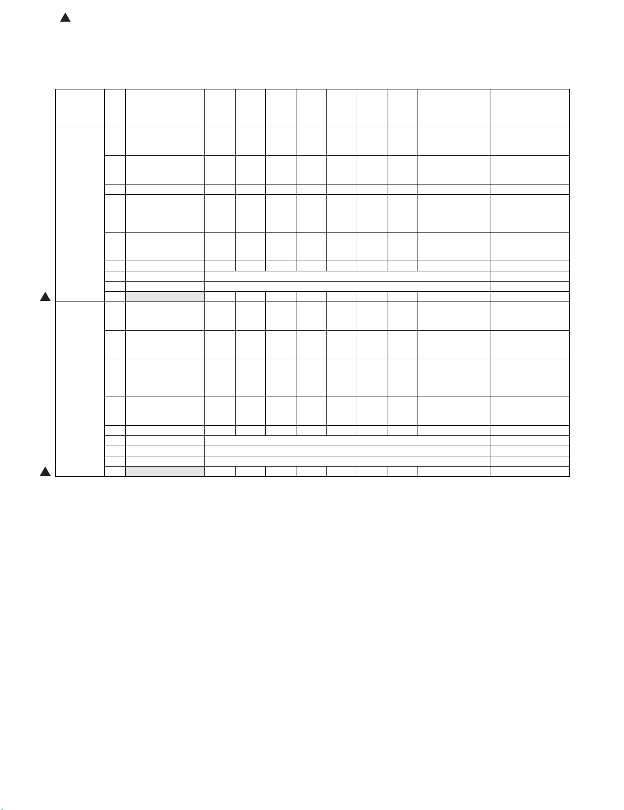
[1] SPECIFICATION
Service Manual
1. MX-FNX6/PNX4
Form Floor type
Transport
speed
Paper
Transport
standard
Pause Switch Available
Tray form Top tray Fixed
Paper size
allowed
Stored paper
weight (Nonstitched)
Stored
Sheets
Stacking
performance
Number of
sheets to be
stitched
Paper weight
to be stitched
Number of
stored sheets
when stapled
(80g/m
Stap le
position
Stapling
method
Adjustment of
Stap le
position
Detection of
no staple
Manual
staple
Life 5 year or 9,900K
Dimensions
(WxDxH)
Weight 46.0kg
Power source DC24V (supplied by the main unit)
Supports 85 sheets/minute
Center alignment
Stacker Section
Offset tray Up and down tray
Top tray A3W, A4W, A3, B4, A4, A4-R, B5, B5Offset tray
R, A5-R, 8K,16K,16KR, Postcard,
11”x17”, 8.5”x14”, 8.5”x13.4”,
8.5”x13”, 8.5"x11", 8.5"x11"-R,
5.5"x8.5"-R,12"x 18", 9"x12",
7.25"x10.5"R
Top tray: 52-205g/m
2
, 16lbs Bond-110lbs Index
Offset tray :52-300g/m
Top tray
250 sheets: A4, 8.5"x11" or less (80g/m
50 sheets: B4, 8.5"x14" or more (80g/m
* A5/5.5x8.5 are feeded from Inserter Tray of Inserter Unit.
Offset tray
3000sheets: A4, 8.5"x11" (80g/m
1500sheets: A3W, A4W, A3, B4, A4-R, B5, B5-R, 8K, 16K,
16KR, 12"x18", 11"x17", 8.5"x14", 8.5"x13.4", 8.5"x13",
8.5"x11"-R, 9"x12" (80g/m
100 sheets:
A5-R*, 5.5"x8.5"-R*, Postcard* (80g/m
*Impossible to Offset.
Non-offset 12 mm or less
(B5R and A5R are 50mm or less)
Offset 12 mm or less
(B5R and A5R are 50mm or less)
Offset volume 30 mm
Stitched 3mm or less
Staple section
50 sheets: A4, 8.5"x11" or less
30 sheets: B4, 8.5"x14" or more
Mixed (same width): 30 sheets
Max. 176g/m
2
(65lbs Index) paper 2 sheets+80g/m2 paper
48 sheets
2
60-105g/m
,16lbs-28lbs Bond
A4, 8.5x11 2-19 sheets 150 bundles
20-50 sheets 150-60 bundles
A4R, B5, 8.5x11R 2-14 sheets 100 bundles
2
)
15-50 sheets 100-30 bundles
Others: 2-14 sheets 100 bundles
15-30 sheets 100-50 bundles
When mixed size:
2-30 sheets 50 bundles
A3 and A4,
B4 and B5,
11x17 and 8.5x17
4 position (Top, Top Slant, Bottom, 2 Staples)
Staple cartridge (5,000 staples)
Changeable by user
-1 - +3.5mm (For 1 position staple only), Adjustment pitch
0.5mm, Controlled by main unit.
Available
(When the inserter is installed, it can be operated on the
operation panel of the main unit.)
640mm x 614mm x 960mm
745mm x 614mm x 960mm (Tray extended)
2
, 16lbs Bond-170 lbs Index
2
, 20lbs Bond)
2
, 20lbs Bond)
2
, 20lbs Bond)
2
, 20lbs Bond)
2
, 20lbs Bond)
MX-FNX6 SPECIFICATION 1 – 1
Power
96W (Include Punch module)
consumption
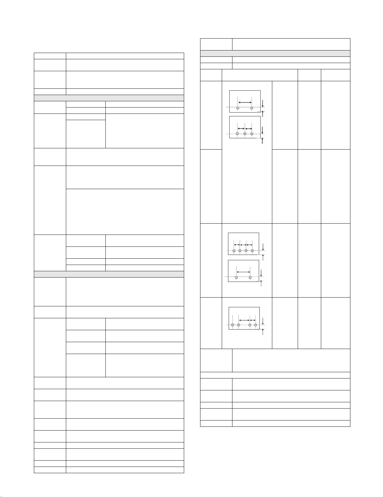
Punch Module for 50 sheets stapling (Option) *3
Form Built in the Finisher
Punch style Reciprocal type
Type Hole location Hole
diameter
2-hole 2-hole:
A:
B
B
80±1mm
B:
12±3mm
2-hole:
A:
70±1mm
B:
North
America
2-hole
3-hole*1
A
A
A
2-hole:
φ6.5mm
φ8.0mm 3-hole:
12±3mm
3-hole:
A:
108±1mm
B:
9.5±3mm
2-hole
4-hole*2
2-hole:
A:
φ6.5mm 4-hole:
80±1mm
B:
12±3mm
4-hole:
A:
80±1mm
B:
12±3mm
4-hole
wide
A:
70±1mm
φ6.5mm A3, A4,
B:
12±3mm
C:
21±1mm
Adjustment of
Punch
position
Feeding direction(X): ±3mm, Adjustment pitch 0.5mm,
Control by main unit.
Y direction: ±2mm, Adjustment pitch 0.4mm, Control by
main unit.
Can be manually adjusted in the B direction.
Manual
Punch
Punchable
Yes (When the inserter is installed, it can be operated on
the operation panel of the main unit.)
52-163g/m
2
,16lbs Bond, 90lbs Index
Paper Weight
Power source In the finisher
Dimensions
130mmx515mmx140mm
(WxDxH)
Weight 1.4kg
*1: Manual (OPE) Switching: 2-hole/3-hole
*2: Manual (OPE) switching 2-hole/4-hole
Paper Size
2-hole:
A3, A4, A4R, B4, B5,
B5-R,
11"x17",
8.5"x14",
8.5" x13.4",
8.5" x13",
8.5"x11",
8.5"x11"-R,
8K, 16K,
16K-R
A3, A4,
11"x17",
8.5"x11"
2-hole:
A3, A4,
A4R, B5,
B5R,
11”x17”,
8.5"x11"-R,
8.5"x14",
8.5"x13.4",
8.5"x13"
A3, B4, A4,
B5, 11"x17",
8.5"x11"
2-hole:
A3, A4,
A4R, B5,
B5R,
11"x17",
8.5"x11"-R,
8.5"x14",
8.5"x13.4",
8.5"x13"
A4-R, B4,
B5, B5-R,
11"x17",
8.5"x14",
8.5"x13.4",
8.5"x13",
8.5"x11",
8.5"x11"-R
Page 3
2. MX-FNX7/PNX4 Saddle finisher (85 only)
Form Floor type
Transport
speed
Paper
Transport
standard
Tray Form Top tray Fixed
Paper sizes
allowed
Stored paper
weight (Nonstitched)
Stored sheets Top tray
Stacking
performance
Number of
sheets to be
stitched
Paper weight
to be stitched
Number of
stored sheets
when stapled
(80g/m
Stap le
Position
Stapling
method
Adjustment of
Stap le
position
Detection of
no staple
Manual
Stap le
Paper sizes
allowed for
saddle
Paper type/
weight
allowed for
saddle
Supports 85 sheets/minute
Center alignment
Stacker section
Offset tray Up-down Offset tray
Saddle Tray Fixed
Top tray A3W, A4W, A3, B4, A4, A4-R, B5, B5Offset tray
R, A5-R, 8K, 16K, 16KR, Postcard,
11"x17", 8.5"x14", 8.5"x13.4",
8.5"x13", 8.5"x11", 8.5"x11"-R,
5.5"x8.5"-R, 12"x18", 9"x12",
7.25"x10.5"R
Top tray: 52 - 205g/m
Offset tray: 52 - 300g/m
250 sheets: A4, 8.5"x11" or less
50 sheets: B4, 8.5"x14" or more
Offset tray
2000 sheets: A4, 8.5"x11"
1000 sheets: A3W, A4W, A3, B4, A4-R, B5, B5-R,
8K,16K,16KR, 12"x18", 11"x17", 8.5"x14", 8.5"x13.4" ,
8.5"x13", 8.5"x11"-R, 9"x12"
100 sheets: A5-R*, 5.5"x 8.5"-R*, Postcard*
*Impossible to Offset.
Non-offset 12 mm or less
(B5R and A5R are 50mm or less)
Offset 12 mm or less
(B5R and A5R are 50mm or less)
Offset volume 30 mm
Stitched 3 mm or less
Staple section
50 sheets: A4, 8.5"x11" or less
30 sheets: B4, 8.5"x14" or more
Mixed size: 30 sheets
Max. 2 x 176g/m
+ 48 sheets x 80g/m
60 - 105g/m
2
(65lbs Index) paper
2
2
,16lbs-28lbs Bond
A4, 8.5x11 2-12 sheets 150 bundles
13-50 sheets 150-40 bundles
A4R, B5, 8.5x11R 2-9 sheets 100 bundles
2
)
10-50 sheets 100-20 bundles
Others: 2-9 sheets 100 bundles
10-30 sheets 100-33 bundles
When mixed size:
2-30 sheets 50 bundles
A3 and A4,
B4 and B5,
11x17 and 8.5x17
4 position (Top, Top Slant, Bottom, 2 Staples)
Staple cartridge (5000 staples) Changeable by user
-1 - +3.5mm (For 1 position staple only), Adjustment pitch
0.5mm, Controlled by main unit.
Available
No
Saddle section
A3W, A3, B4, A4-R, B5-R, 11"x17", 8.5"x14", 8.5"x11"-R,
12"x18"
60 - 90g/m
176g/m
2
, 16lbs-24lbs Bond, Cover is possible up to
2
.
2
, 16lbs Bond-110lbs Index
2
, 16lbs Bond-170lbs Index
paper
Stit ching
2-point center stitch
method
Stitched
15 sheets
sheet
Folding
Center folding
location
Loading
number of
sheet
Adjustment of
Centre staple
2 - 5 sheets staple: 30 bundles
6 - 10 sheets staple: 15 bundles
11 - 15 sheets staple: 10 bundles
±3mm (Feeding direction), Adjustment pitch 0.2mm,
Controlled by main unit.
position
Adjustment of
Centre
±3mm (Feeding direction), Adjustment pitch 0.2mm,
Controlled by main unit.
folding
position
Detection of
Available
no staple
Stapling
method
Staple cartridge (2000 staples) x2
Changeable by user
Reliability MCBJ in compliance with the main unit
MCBF in compliance with the main unit
Life 5 year or 9,900K
Dimensions
(W x D x H)
640mm x 614mm x 960mm
745mm x 614mm x 960mm (Tray extended)
Weight 60.6Kg
Power
DC24V (supplied by the main unit)
Source
Power
96W (Include Punch module)
Consumption
Manual
No
Stap le
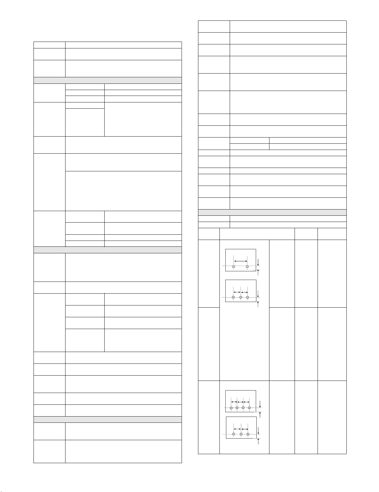
Punch Module for 50 sheets stapling(Option) *3
Form Built in the finisher
Punch style Reciprocal
Type Hole location
2-hole 2-hole
A:
80±1mm
B:
12±3mm
B
Hole
diameter
2-hole:
φ6.5mm
Paper Size
2-hole:
A3, A4,
A4-R, B4,
B5, B5-R,
11"x17",
8.5"x14",
8.5" x13.4",
8.5"x13",
"8.5"x11",
8.5"x11"-R,
8K, 16K,
16K-R
A3, A4,
11"x17",
8.5"x11"
2-hole:
North
America
2-hole
3-hole*1
A
A
B
2-hole:
φ8.0mm 3-hole:
A:
70±1mm
B:
12±3mm
A3, A4,
3-hole:
A:
108±1mm
B:
9.5±3mm
A4R, B5,
B5R,
11"x17",
8.5"x11"-R,
8.5"x14",
8.5"x13.4",
8.5"x13"
2-hole
4-hole*2
A
A
A
A
A
B
B
2-hole:
A:
80±1mm
B:
12±3mm
4-hole:
A:
80±1mm
B:
12±3mm
φ6.5mm 4-hole:
A3, B4, A4,
B5, 11"x17",
8.5"x11"
2-hole:
A3, A4,
A4R, B5,
B5R,
11"x17",
8.5"x11"-R,
8.5"x14",
8.5"x13.4",
8.5"x13"
MX-FNX6 SPECIFICATION 1 – 2
Page 4
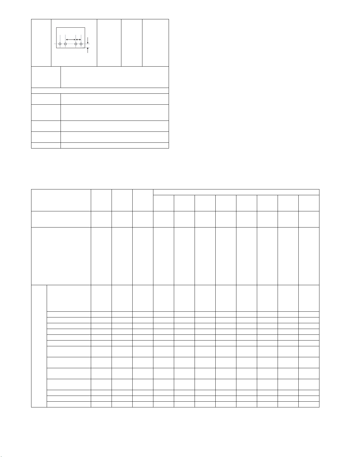
4-hole
wide
Adjustment of
Punch
position
C
A
Feeding direction(X): ±3mm, Adjustment pitch 0.5mm,
Controlled by main unit.
Y direction: ±2mm, Adjustment pitch 0.4mm, Control by
B
A:
70±1mm
B:
12±3mm
C:
21±1mm
main unit.
B-direction can be adjustable manually.
Manual
No
Punch
Punchable
Paper Weight
2-hole/ 2-hole3-hole: 52-163g/m
4-hole/ 4-hole-broad space: 52-163g/m
90lbs Index
Power
Supplied by the finisher
Source
Dimensions
130mm x 515mm x 140mm
(WxDxH)
Weight 1.4kg
*1: Manual (OPE) switching: 2-hole/3-hole
*2: Manual (OPE) switching: 2-hole/4-hole
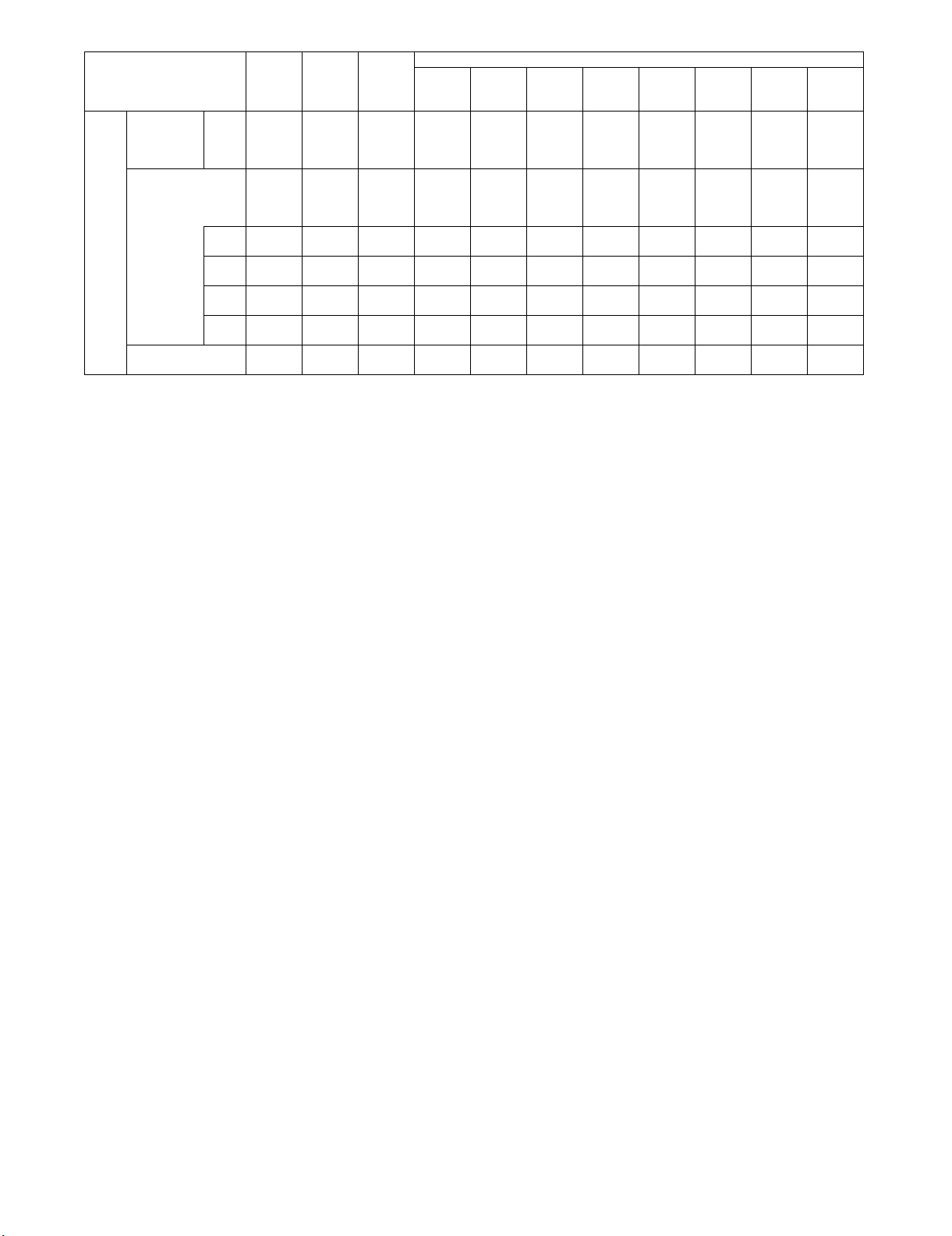
3. Paper size/Type/Weight
φ6.5mm A3, A4,
A4-R, B4,
B5, B5-R,
11" x17" ,
8.5"x14",
8.5" x13.4",
8.5"x13",
8.5"x11",
8.5"x11"-R
2
/16lbs Bond-90lbs Index
2
/16lbs Bond-
2- sided
pass
Minimum paper weight 60g/m
(16lbs
bond)
Maximum paper weight 205g/m
(40lbss
bond)
(110lbss
index)
(65lbs
cover)
2
2
Reverse
Output
Pass
52g/m2
(14lbs
bond)
205g/m2
(40lbss
bond)
(110lbss
index)
(65lbs
cover)
Straight
Output
Pass
52g/m2
(14lbs
bond)
300g/m2
(40lbs
bond)
(140lbs
index)
(100lbs
cover)
Top tr ay Of fs et
tray
52g/m2
(14lbs
bond)
205g/m2
(40lbs
bond)
(110lbs
index)
(65lbs
cover)
52g/m2
(14lbs
bond)
300g/m2
(40lbs
bond)
(140lbs
index)
(100lbs
cover)
Saddle Finisher/ Finisher (For 85 sheets)
At the
staple
60g/m2
(16lbs
bond)
105g/m2
(28lbs
bond)
Punch
(2-
holes)
52g/m2
(14lbs
bond)
163g/m
(90lbs
Index)
2
Punch
(2/3 -
holes)
52g/m2
(16lbs
bond)
163g/m2
(90lbs
Index)
Punch
(2/4 -
holes)
52g/m2
(14lbs
bond)
163g/m2
(90lbs
Index)
As for
the
cover
sheet,
Even
2
176g/m
is
possible
Paper
Thin paper No Yes
type
(Even
52g/m
is
possible)
2
Ye s
(Even
52g/m2
is
possible)
Ye s
(Even
52g/m2
is
possible)
Ye s
(Even
52g/m2
is
possible)
No Yes
(Even
52g/m2
is
possible)
Ye s
(Even
52g/m2
is
possible)
Ye s
(Even
52g/m2
is
possible)
Plai n p a p er Ye s Yes Yes Yes Yes Yes Yes Ye s Yes Yes Yes
Rec y c l e d p a per Yes Yes Yes Yes Yes Yes Ye s Yes Yes Yes Yes
Colored paper Yes Yes Yes Yes Yes Yes Yes Yes Yes Yes Yes
Le tt er head Yes Ye s Yes Yes Yes Yes Ye s Yes Ye s Yes Yes
Pre-printed paper Yes Yes Yes Yes Yes Yes Yes Yes Yes Yes Yes
Pre-punched paper Yes Yes Yes Yes Yes Yes No No No No Yes
Heavy paper1
(106-128g/m
Heavy paper2
(129-176g/m
Heavy paper3
(177-205g/m
Heavy paper4
(206-300g/m
2
)
2
)
2
)
2
)
Ye s Ye s Ye s Yes Ye s Ye s Ye s Ye s Ye s Ye s Ye s
Ye s Ye s Ye s Yes Ye s Ye s Ye s Ye s Ye s Ye s Ye s
YesYesYesYesYesNoNoNoNoNoNo
No No Yes No Yes No No No No No No
Tab paper No Yes Yes Yes Yes Yes Yes Yes Yes Yes No
Transparency paper No No Yes Yes No No No No No No No
Label paper No No Yes Yes No No No No No No No
Punch
(4-holes
wide)
52g/m2
(14lbs
bond)
163g/m2
(90lbs
Index)
Ye s
(Even
52g/m2
is
possible)
Saddle
tray
60g/m2
(16lbs
bond)
90g/m2
(24lbs
bond)
As for
the
cover
sheet,
Even
176g/m
is
possible
No
2
MX-FNX6 SPECIFICATION 1 – 3
Page 5

2- sided
pass
Paper
12"x18"
size
(A3W)
Ledger
(11"x17")
Ledger
(11"x17")
Zfolding
Legal
(8.5"x14")
Legal
(8.5"x14")
Z folding
Mexican
Legal
(8.5"x13.4")
Foolscap
(8.5"x13")
Letter
(8.5"x11")
Letter R
(8.5"x11"R)
Letter R
(8.5"x11"R)
Z folding
Invoice
(5.5"x8.5")
Invoice R
(5.5"
x8.5"R)
Exective R
(7.25"x10.5")
9x12 (A4W) 305
A3 297
A3
Z folding
B4 257
B4
Z folding
A4 297
A4-R 210
A4-R
Z folding
B5 257
B5-R 182
A5 210
A5-R 148
SRA3 320
SRA4 320
318x234.75mm Yes Yes Yes No No No No No No No No
312.5x220mm Yes Yes Yes No No No No No No No No
318x469.5mm Yes Yes Yes No No No No No No No No
312.5x440mm Yes Yes Yes No No No No No No No No
8K 270
16K 270
16K-R 195
305
x457
279
x432
279
x216
216
x356
216
x178
216
x340
216
x330
279
x216
216
x279
216
x140
216
x140
140
x216
184
x266
x229
x420
297
x210
x364
257
x182
x210
x297
210
x148
x182
x257
x148
x210
x450
x225
x390
x195
x270
Reverse
Output
Pass
YesYesYesYesYesNoNoNoNoNoYes
Ye s Ye s Ye s Yes Ye s Ye s Ye s Ye s Ye s Ye s Ye s
-----------
Ye s Ye s Ye s Yes Ye s Ye s Ye s y e s
-----------
Ye s Ye s Ye s Yes Ye s Ye s Ye s y e s
Ye s Ye s Ye s Yes Ye s Ye s Ye s y e s
Ye s Ye s Ye s Yes Ye s Ye s Ye s Ye s Ye s Ye s N o
Ye s Ye s Ye s Yes Ye s Ye s Ye s y e s
-----------
NoNoNo--------
Ye s Ye s Ye s Yes ye s
Yes Yes Yes Yes Yes Yes No No No No No
YesYesYesYesYesNoNoNoNoNoNo
Ye s Ye s Ye s Yes Ye s Ye s Ye s Ye s Ye s Ye s Ye s
-----------
Ye s Ye s Ye s Yes Ye s Ye s Ye s y e s
-----------
Ye s Ye s Ye s Yes Ye s Ye s Ye s Ye s Ye s Ye s N o
Ye s Ye s Ye s Yes Ye s Ye s Ye s y e s
-----------
Ye s Ye s Ye s Yes Ye s Ye s Ye s y e s
Ye s Ye s Ye s Yes Ye s Ye s Ye s y e s
NoNoNo--------
Ye s Ye s Ye s Yes ye s
YesYesYesNoNoNoNoNoNoNoNo
YesYesYesNoNoNoNoNoNoNoNo
Ye s Ye s Ye s Yes Ye s Ye s Ye s Ye s Ye s Ye s N o
Ye s Ye s Ye s Yes Ye s Ye s Ye s Ye s Ye s Ye s N o
Ye s Ye s Ye s Yes Ye s Ye s Ye s y e s
Straight
Output
Pass
Top tr ay Of fs et
tray
(Impossi
ble to
offset)
(Impossi
ble to
offset)
Saddle Finisher/ Finisher (For 85 sheets)
At the
staple
No No No No No No
No No No No No No
Punch
(2-
holes)
Punch
(2/3 -
holes)
(2-holes)
(2-holes)
(2-holes)
(2-holes)
(2-holes)
(2-holes)
(2-holes)
(2-holes)
(2-holes)
Punch
(2/4 -
holes)
yes
(2-holes)
yes
(2-holes)
yes
(2-holes)
yes
(2-holes)
Ye s Ye s Ye s
yes
(2-holes)
Ye s Ye s No
yes
(2-holes)
yes
(2-holes)
Punch
(4-holes
wide)
Ye s Ye s
Ye s No
Ye s No
Ye s Ye s
Ye s Ye s
Ye s Ye s
Ye s No
Saddle
tray
MX-FNX6 SPECIFICATION 1 – 4
Page 6
Paper
Postcard 100
size
Special-Custom size No Yes Yes Yes yes
(Custom
Range)
Special-Size
uncertain
x148
min
Main
max
Main
min
Sub
max
Sub
*1: Cover and back cover only.
*2: 2-holes only.
2- sided
pass
Reverse
Output
Pass
No No Yes Yes yes
- 140
- 320
(12.5)
- 182
(7.25)
- 470
(18.5)
NoYesYesYesNoNoNoNoNoNoNo
(5.5)
Straight
Output
Pass
100
(4.0)
320
(12.5)
140
(5.5)
470
(18.5)
Top tr ay Of fs et
100
(4.0)
320
(12.5)
140
(5.5)
470
(18.5)
tray
(Impossi
ble to
Offset)
(Impossi
ble to
Offset)
140
(5.5)
306
(12.1)
140
(5.5)
470
(18.5)
Saddle Finisher/ Finisher (For 85 sheets)
At the
staple
No No No No No No
No No No No No No
Punch
holes)
------
------
------
------
(2-
Punch
(2/3 -
holes)
Punch
(2/4 -
holes)
Punch
(4-holes
wide)
Saddle
tray
MX-FNX6 SPECIFICATION 1 – 5
Page 7
1
:07’.07.27
MX-FNX6
[2] MAINTENANCE LIST
✕ : Check {: Clean S: Replace U: Adjust ✩ : Lubricate : Shift position
(Clean, replace, or adjust as needed.)
Service Manual
Unit name No. Part name
Finisher
(for 85-sheet
machine)
[MX-FNX6]
1
Saddle
finisher
(for 85-sheet
machine)
[MX-FNX7]
1
1 Transport rollers ✕ { { { { { { When there is dirt,
2 Transport paper guide ✕ { { { { { { When there is dirt,
3Gears ✕ ✕ ✕ ✕ ✕ ✕ ✕ UKOG-0307FCZZ
4 Discharge brush ✕ ✕ ✕ ✕ ✕ ✕ ✕ When there is dirt,
5 Sintered bearing ✕ ✕ ✕ ✕ ✕ ✕ ✕ Lubricate when an
6 Sensor ✕ { { { { { { Clean by air
7 Edge binding stapler Replacement reference: Replace the unit after 500K of staple.
8 Punch Replacement reference: Replace the unit after 1,000K of panch.
9
Drag roller ✕ SSSSSS
1 Drive roller ✕ { { { { { { When there is dirt,
2 Follower roller ✕ { { { { { { When there is dirt,
3 Discharge brush ✕ ✕ ✕ ✕ ✕ ✕ ✕ When there is dirt,
4 Sintered bearing ✕ ✕ ✕ ✕ ✕ ✕ ✕ Lubricate when an
5 Sensor ✕ { { { { { { Clean by air
6 Edge binding stapler Replacement reference: Replace the unit after 500K of staple.
7 Center binding stapler Replacement reference: Replace the unit after 200K of staple.
8 Punch Replacement reference: Replace the unit after 1,000K of panch.
9
Drag roller ✕ SSSSSS
When
calling
500K 1000K 1500K 2000K 2500K 3000K
NOTE: Discharge brush cleaning
Wipe the brush with wet cloth with a small amount of water. (Recommend)
Handle the brush carefully.
Life judgement
(Reference)
abnormal sound is
heard.
abnormal sound is
heard.
Tool, oil, chemicals
Procedure
Treatment after
procedure
wipe with wet cloth
and water.
wipe with wet cloth
and water.
wipe brush part with
wet cloth and water.
* Refer to the NOTE:
Tellus oil:
0CW4110K701//
wipe with wet cloth
and water.
wipe with wet cloth
and water.
wipe brush part with
wet cloth and water.
* Refer to the NOTE:
Silicon oil
MX-FNX6 MAINTENANCE LIST 2 – 1
Page 8
M18
S5
S8
S6
M10
M4
SOL2
S7
S10
S1
S9
S12
Tray upper limit
SW
S13
M19
M2
SOL1
S11
MX-FNX6
[3] MECHANISM
Service Manual
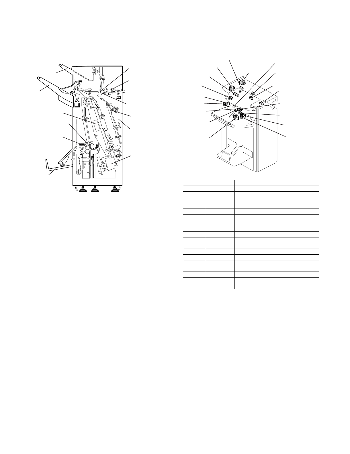
1. Composition layout (* In the figure: For the MX-FNX7 only)
Proof tray
Tr ay
assembly
* Center binding
stapler
* Folding plate
* Folding roller
Tr ay
*
paper folding
section
1) Proof branch, staple branch
The paper path is selected between the path to the proof tray
and the path to the upper tray depending on presence of sort
or staple.
2) Proof tray
When the sort mode and the staple mode are not selected,
copy paper is discharged to this tray.
3) Tray assembly
This tray lifts up or moves down in the sort mode depending on
the copy discharge quantity (the number of copy sets).
4) Tray paper folding section (The MX-FNX7 only)
Center binding copy is discharged to this tray in the sort mode.
5) Pre-stack section
The first page of the second or later sets is switch-back transported and kept in standby, and fed together with the second
page to the staple tray.
6) Center binding staple section (The MX-FNX7 only)
Sheets of copy paper are aligned by the alignment roller and
the jogger fence, performing stapling.
2. Electric parts layout
Proof branch
pawl
Punch unit
Staple branch
pawl
Pre-stack
branch pawl
Pre-stack tray
Edge binding
stapler
Signal name Parts name
M2 UPTRS_M Upper transport motor
M4 EXIT_M Paper exit motor
M10 STRLVI_M Return roller oscillation motor
M18 SFT_M Shift motor
M19 EXGPLT_M Paper exit guide plate open/close motor
S1 FINENT Inlet sensor
S5 SFTROLHP Shift HP sensor
S6 UPTRYEXT Shift tray paper exit sensor
S7 EXGPLTHP Paper exit guide plate HP sensor
S8 UTRPHNST Staple mode paper surface detection
S9 UTRPHSTP Shift mode paper surface detection
S10 PRFTRYEX Proof tray paper exit sensor
S11 PRFTRYFL Proof tray full sensor
S12 UPTRYLMT Shift mode rear edge detection
S13 STKROLHP Oscillation return roller HP sensor
SOL1 UPJCTG_S Proof branch pawl SOL
SOL2 LOJCTG_S Staple branch pawl SOL
- - Tray upper limit SW
MX-FNX6 MECHANISM 3 – 1
Page 9
* SOL5
* S27
* M17
S18
S17
M13
M20
S14
M6
S15
M15
* M23
* M22
M5
S16
*S32
PCB: STP:
Control plate
PCB: Main:
Control plate
M21
M3
M1
Door SW
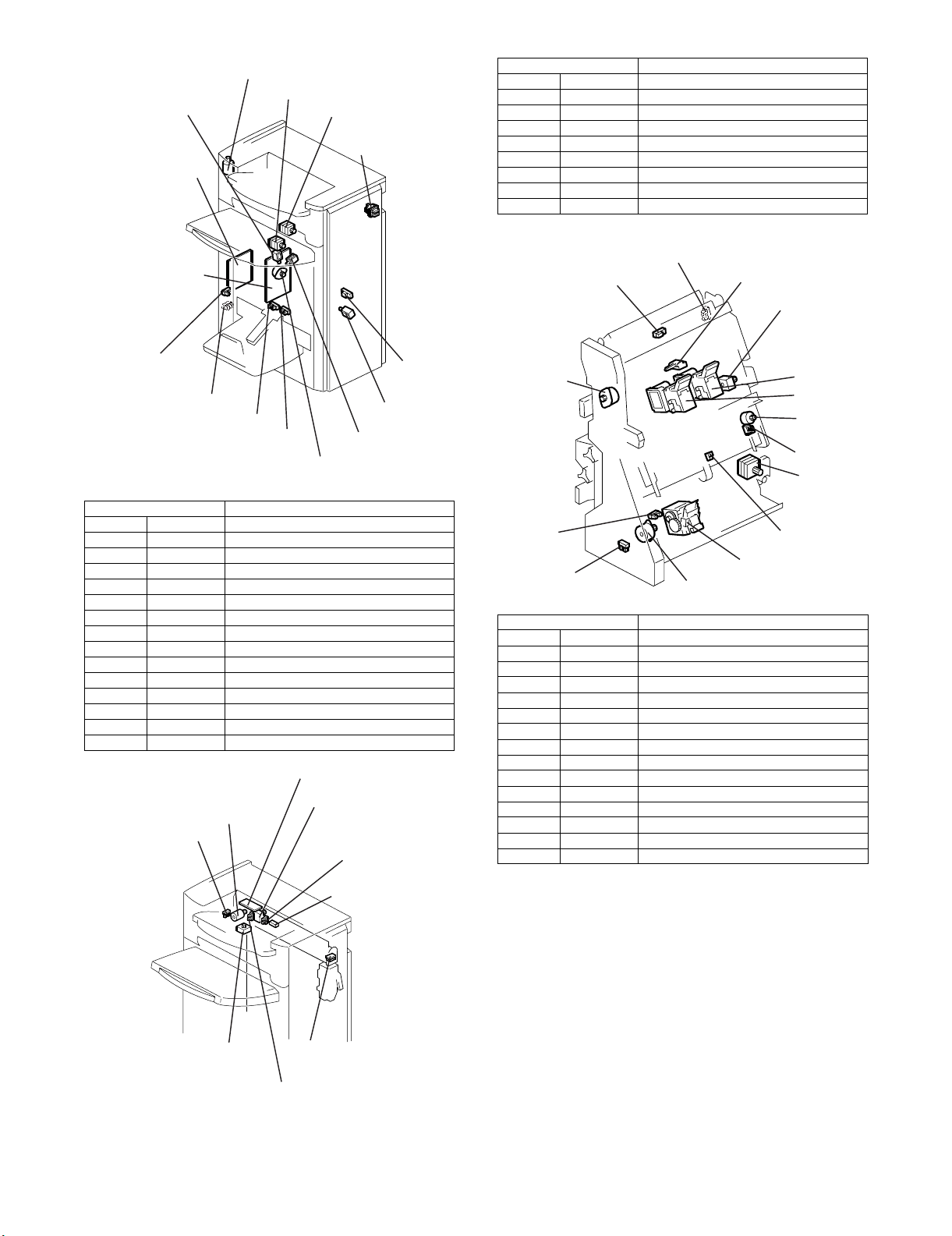
Signal name Parts name
M7 STSMOV_M Horizontal resist detection sensor shift motor
M9 PNCHMV_M Punch shift motor
M24 PNCH_M Punch drive motor
S21 PNCHMVHP Punch shift HP sensor
S22 PAPPOSHP Horizontal resist detection HP sensor
S24 PNCHENC Punch HP sensor
S3 PAPPOS Horizontal resist detection sensor
S4 PNCHHPFL Punch dust full sensor
- - PCB: Punch: Control plate
* S19
S20
* S34
* S33
SOL4
SOL3
M14
* MX-FNX7 only
Signal name Parts name
M1 ENT_M Inlet motor
M3 LOTRS_M Lower transport motor
M14 POP_M Beating roller drive motor
M21 TRYLFT_M Tray up/down motor
S2 PSTRYEXT Staple paper exit sensor
S19 UPTRFLSD Full sensor: Center binding (*)
S20 UPTRFLNS Full sensor: Without center binding
S33 SDLFLLR Center binding tray full sensor (*)
S34 SDLFLLF Center binding tray full sensor (*)
SOL3 POS_S Beating SOL
SOL4 TEGPRS_S Rear edge holding SOL
SOL5 SDLPRS_S Center binding holding SOL (*)
- - PCB: STP: Control plate
- - PCB: Main: Control plate
- - Door SW
PCB: Punch: Control plate
M7
M24
S24
S22
S2
Signal name Parts name
M5 BLT_M Discharge motor
M6 STPMV_M Stapler shift motor
M13 STPROT_M Stapler slant motor
M15 JOG_M Jogger motor
M17 BDJCTG_M Bundle branch open/close (*)
M20 STPMOV_M Stapler
M22 SDLSTF_M Center binding stapler (*)
M23 SDLSTR_M Center binding stapler (*)
S14 STPTRPAP Stapler tray paper presence sensor
S15 JOGHPS Jogger HP sensor
S16 BLTHPS Discharge pawl HP sensor
S17 CONSTPHP Stapler shift HP sensor
S18 STPROTHP Stapler slant HP sensor
S27 STJCTGHP Bundle branch open/close HP (*)
S32 STKPRST Lead edge detection sensor (*)
M9
S21
S4
S3
MX-FNX6 MECHANISM 3 – 2
Page 10
* S31
When in the proof mode:
Staple branch pawl
Proof branch pawl
In the shift mode:
* S25
* M12
* M11
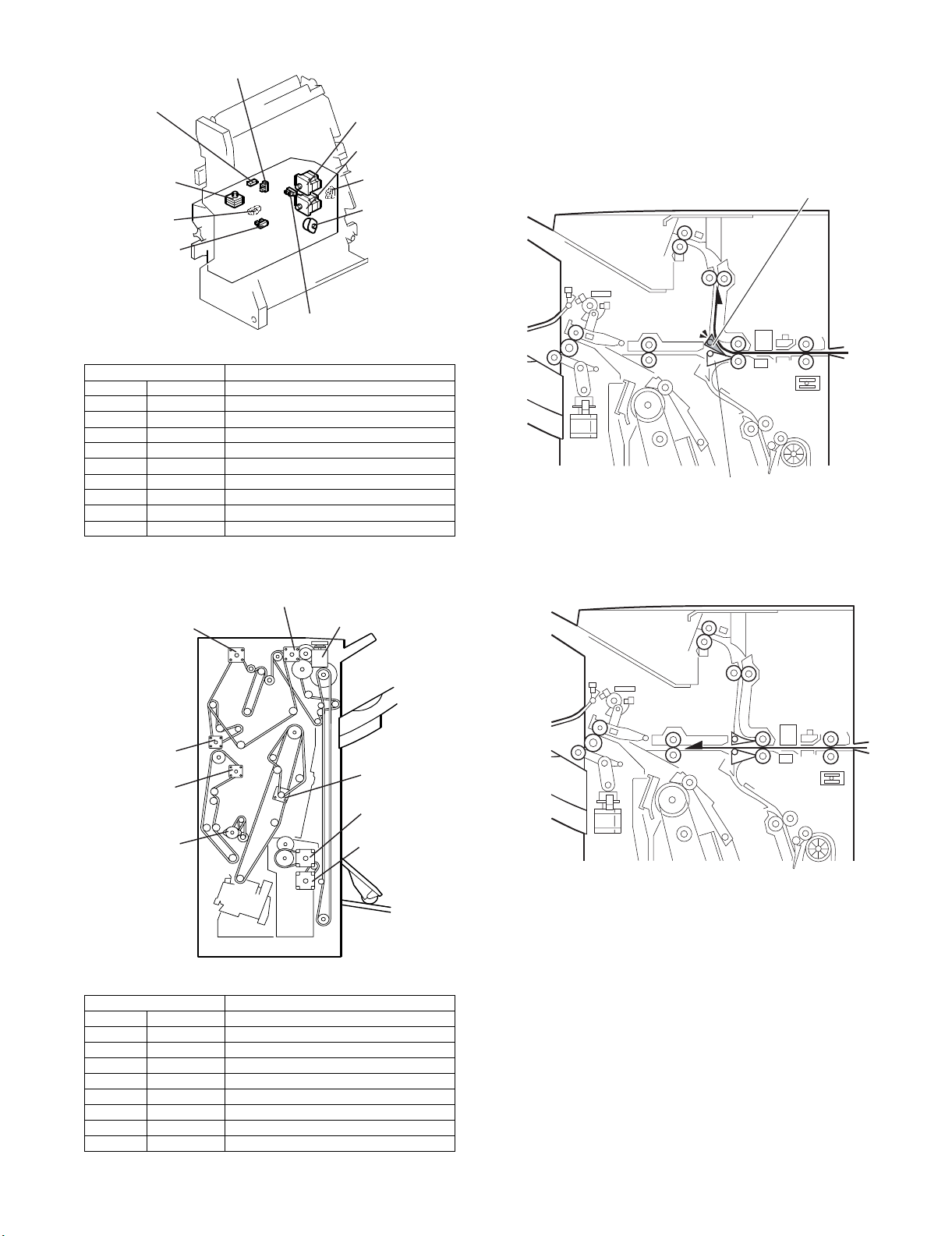
4. Branch mechanism
1) Paper is branched to the three directions by the proof branch
pawl and the staple branch pawl.
2) In the proof mode, when discharging to the proof tray, copy
paper is transported to the proof tray by the proof branch pawl.
*M8
* S26
* S28
* S30
* MX-FNX7 only
Signal name Parts name
M8 DRRLVI_M Drive roller oscillation motor (*)
M11 FLDPLT_M Folding plate drive motor (*)
M12 FLDROL_M Folding roller motor (*)
M16 TALFNC_M Rear edge fence motor (*)
S25 CLPROLHP Drive roller HP sensor (*)
S26 FLDUNENT Reach sensor (*)
S28 FLDBTMHP Rear edge fence HP sensor (*)
S29 FLDPLTHP Folding plate HP sensor (*)
S30 FLDCMHP Folding HP sensor (*)
S31 FLDUNEXT Folding pass sensor (*)
3. Drive layout
M4
M2
* S29
* M16
3) In the shift mode, the proof branch pawl and the staple branch
pawl do not operate, and copy paper is transported to the shift
tray.
M21
M1
M3
M14
* MX-FNX7 only
Signal name Parts name
M1 ENT_M Inlet motor
M2 UPTRS_M Upper transport motor
M3 LOTRS_M Lower transport motor
M4 EXIT_M Paper exit motor
M5 BLT_M Discharge motor
M11 FLDPLT_M Folding plate drive motor (*)
M12 FLDROL_M Folding roller motor (*)
M14 POP_M Beating roller drive motor
M21 TRYLFT_M Tray up/down motor
M5
* M12
* M11
MX-FNX6 MECHANISM 3 – 3
Page 11
4) In the staple mode, the staple branch pawl operates to transport copy paper to the staple section.
In the staple mode:
Staple branch pawl
5. Pre-stack mechanism
Four sheets can be discharged with max. three sheets of pre-stack.
In the example below, descriptions are made on discharge of three
sheets with two sheets of pre-stack.
1) Stapling the first set is performed.
3) The first sheet of the second set is transported from the prestack tray. At the same time, transport of the second sheet of
the second set is started.
4) Transport of the first sheet of the second set is completed. At
the same time, the rear edge of the second sheet of the second set passes the branch pawl.
Pre-stack Branch pawl
2nd sheet of 2nd set
1st sheet of 2nd set
Bundle of 1st set
2) The first sheet of the second set is switch-back transported to
the pre-stack tray.
Pre-stack tray
5) The first sheet and the second sheet of the second set are
switch-back transported together to the pre-stack tray.
6) Stapling of the first set is completed. At the same time, the first
sheet and the second sheet of the second set are transported
together from the pre-stack. Transport of the third sheet of the
second set is also started.
3rd sheet of 2nd set
MX-FNX6 MECHANISM 3 – 4
Page 12

7) The first set is discharged.
8) The first sheet, the second sheet, and the third sheet of the
second set are discharged together to the staple tray.
6. Rise-fall mechanism
<Tray assembly>
The Tray assembly rises or falls depending on the copy paper
quantity (paper stack height) discharged on the tray. The height is
always adjusted by the OFF state of the paper surface sensor.
• When discharging in the shift mode:
Paper surface sensor on the end fence side
• When discharging in the staple mode:
Paper surface sensor on the filler
Filler paper surface sensor
Lift motor
1) Falling operation
When the discharged copy paper is loaded on the tray and the
filler is lifted to turn on the paper surface detection sensor
lower for 3 sec or more, the lift motor rotates to fall the shift
tray. The falling operation varies depends on the mode.
Staple:
The lift motor rotates for a certain time to lower the tray height
for a certain interval, adjusting the height.
Shift:
The shift tray lifts up to the position where the paper surface
sensor is turned on. Then, the tray falls to turn off the paper
surface sensor, adjusting the height.
The shift tray full detection is made when the sensor is turned
on and it is displayed on the operation panel, and copying is
stopped. Cancel is made by removing copy paper.
2) Rising operation
When copy paper is removed from the shift tray and the paper
surface sensor upper is turned on, the shift tray rises. It stops
when the sensor is turned off.
7. Staple jogger mechanism
A. Stack mechanism
Copy paper branched to the staple tray is transported to the staple
tray. After the staple paper exit sensor turns off (A4Y), the alignment roller SOL turns on for a certain time (varying depending on
the size and the quantity). The alignment roller pushes paper to the
tray stopper to align the rear edges of paper.
B. Jogger mechanism
Copy paper rear edges are aligned by stack operation of (A), then
copy paper side edges are aligned by jogger operation.
First, the jogger fence closes to 7mm open from the right and the
left edges of paper by the ON signal (copy start).
When the lead edge of the transported paper passes the staple
paper exit sensor, the jogger fence closes 5mm to receive paper
and performs the operation of (A) to align the rear edges.
Then, the jogger fence closes 2.6mm furthermore to align the side
edges.
When the jogger operation is completed, the jogger fence opens
again to 7mm open from the paper edges and the machine enters
the standby state of the next paper.
Shift tray lower
limit sensor
Jogger fence
Jogger motor
Jogger HP
sensor
Paper surface
sensor on the end
fence side
Sliding roller
MX-FNX6 MECHANISM 3 – 5
Page 13

C. Stapler
The stapling operation is performed by the drive motor in the stapler. When an overload of the motor is generated by a staple jam,
etc., “Staple jam” is displayed on the operation panel.
The stapler is provided with the cartridge set sensor and the staple
end sensor. When they are OFF, the staple supply message is displayed on the operation panel.
When staple end occurs during copying, the job is completed and
the staple supply message is displayed.
When a staple jam occurs, copying is stopped.
Staple hammer
D. Stapler shift mechanism
The stapler shifts horizontally or rotates to make stapling according
to the four staple modes.
1) Staple shift mechanism
The stapler is supported by the rod, and shifted horizontally by
the timing belt. When the copy start key is pressed, the jogger
fence moves to the standby position. Then the stapler shift
motor turns ON to shift the stapler to the stapling position, and
the stapler enters the standby state of stapling.
The shift quantity differs depending on the paper size and the
stapling position.
When stapling at two positions, the front side is stapled first,
then the rear side is stapled.
2) Staple rotating mechanism
In one-position diagonal staple mode, the stapler is shifted horizontally and then rotated diagonally. Then stapling is performed. Rotation is made by the stapler rotation motor.
Staple motor
Stapler
Set sensor End sensor
Rear edge guide
Arm
Stapler rotation motor
Rear edge
reference fence
Oscillation SOL
Stapler
shift motor
E. Rear edge holding mechanism
In the edge binding or the center binding bookmaking mode (MXFNX7 only), curls and slacks on paper stacked to the rear edge reference fence are pressed to the staple tray, allowing the next paper
to feed to the rear edge reference fence, improving the alignment
accuracy when binding.
1) When stacking paper to the rear edge reference fence (staple
tray), paper is first aligned by the jogger fence (horizontal
alignment), then aligned by the shift roller (vertical alignment).
When the horizontal alignment and the vertical alignment are
completed, the oscillation SOL is turned ON to move the rear
edge guide to the holding position via the arm.
2) When the next paper enters the staple tray, the SOL is turned
OFF to save the rear edge guide to the standby position. After
completion of alignment operation, the SOL is turned ON again
to hold the rear edge section of paper.
3) The above operations are repeated until the last paper and
binding are completed. When binding operation is completed,
the SOL is turned OFF to save the rear edge guide to the
standby position until the next job is started.
MX-FNX6 MECHANISM 3 – 6
Page 14

F. Center binding holding mechanism
Discharge fence 1
Center binding staple
First set paper bundle
Discharge fence 2
(MX-FNX7 only)
In the center binding bookmaking mode, curls and slacks on paper
stacked on the staple tray are pressed to the staple tray side,
improving the paper edge detection accuracy and preventing paper
bundle shift when binding.
1) In the center binding bookmaking mode, paper is stacked to
the staple tray and vertical alignment and horizontal alignment
are completed. Then, paper bundle is transported to the center
binding stapler position at the center of the staple tray, and the
paper bundle rear edge is detected by the photo sensor.
The paper bundle is stopped according to the detection information, and binding is performed.
2) During these operations (after completion of horizontal/vertical
alignment, transport of paper bundle to the center binding position, completion of binding - *), the holding SOL is turned ON,
and the roller is moved to the holding position via the arm to
hold the paper bundle.
3) After completion of binding, the holding SOL is turned OFF to
save the roller to the standby position until the next job is
started.
* When the paper for center binding bookmaking is A3T, B4T, DLT,
or LG size, in order to detect the paper bundle rear edge with the
photo sensor, the paper bundle is moved up and down (normal/
reverse operation) inside the staple tray. When in reverse operation (moving down), the holding SOL is turned OFF to save the
roller in order not to prevent reverse operation of the paper bundle by the roller.
8. Center binding staple mechanism (MX-FNX7 only)
1) The first set is transported to the center binding staple section.
2) The center binding stapling of the first set is completed.
Discharge fence 2
Holding SOL
Arm
Holding roller
Discharge fence 1
3) The discharge fence 1 starts transport of the first set, and the
bundle branch guide pushes the first set to the transport roller
to start transport to the folding process section.
Bundle branch guide
Transport roller
Discharge fence 2
Discharge fence 1
MX-FNX6 MECHANISM 3 – 7
Page 15

4) Transport of the first set is completed. At the same time, the
second set is transported to the staple section.
Second set
paper bundle
Folding roller
6) The first set folding is completed and discharged. At the same
time, the second set center binding stapling is completed.
5) The folding plate advances and the folding roller rotates to fold
the first set at the center. At the same time, transporting of the
second set to the center binding staple position is completed.
Folding plate
9. Discharge mechanism
After completion of stapling, the discharge motor turns ON to drive the discharge belt, discharging copy paper from the staple tray with the discharge fence attached to the belt.
At that time, the paper exit guide plate remains in the open state until the paper bundle lifted by the discharge pawl moves by a certain distance
from the paper exit roller.
Then, the paper exit guide closes and the paper bundle is discharged to the shift tray by the paper exit roller.
The paper exit guide plate is opened or closed by rotation of the cam caused by the rotation of the paper exit guide plate open/close motor to
move the link up and down.
When discharging paper to the shift tray, the discharge motor is stopped for 300ms to prevent excessive pushing up.
After temporary stopping, the discharge motor is driven again and stops under the state where the discharge fence turns on the home position
sensor filler.
There are two discharge fences to improve productivity of small-lot binding.
MX-FNX6 MECHANISM 3 – 8
Page 16

Discharge belt HP sensor
Guide plate open/close motor
Discharge
motor
Discharge fence
Paper exit
guide plate
MX-FNX6 MECHANISM 3 – 9
Page 17

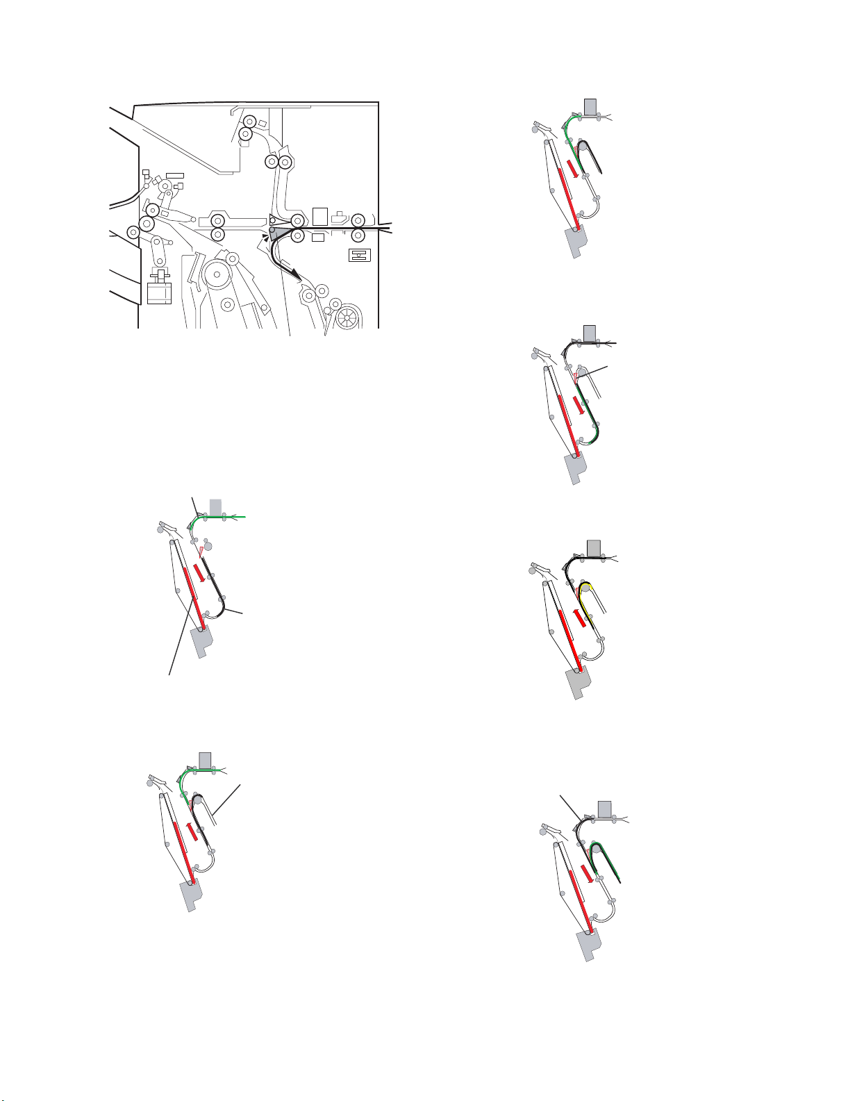
10. Punch mechanism
Punch unit
Punching is performed for every sheet by punching two holes at the
rear edge of copy paper.
For diagonal shift of copy paper, skew correction is made. For horizontal shift, the punch unit is shifted accordingly.
1) Copy paper is discharged from the machine.
Machine paper exit roller
2) The finisher inlet sensor detects copy paper.
Finisher inlet roller
5) The horizontal resist sensor detects horizontal shift of copy
paper.
Horizontal resist sensor
6) The punch unit is moved by the detected quantity of horizontal
shift to complete punching.
Inlet sensor
3) Copy paper is pushed against the finisher inlet roller to correct
diagonal skew.
7) The punch unit returns to the home position.
4) Diagonal skew is corrected and copy paper is transported.
11. Punch dust collection mechanism
Punch dust made by punching is moved to the front side of the machine by the transport belt to fall into the punch dust holder.
Transport beltTransport belt
Punch dust collection unit
Punch dust collection unit
The height sensor of the punch dust collection unit detects the punch dust height in the punch dust holder, detecting full.
MX-FNX6 MECHANISM 3 – 10
Page 18

Height sensorHeight sensor
MX-FNX6 MECHANISM 3 – 11
Page 19

When this gear is pulled toward you,
the drive is released.
Tray assembly
MX-FNX6
[4] REPLACEMENT AND ADJUSTMENT
Service Manual
1. External cover replacement
Upper cover
Upper cover center
Rear cover
Paper exit
port cover
Blind cover
Left side cover
1) Open the front door, remove the screw (1 screw), and remove
the upper cover center.
Point:
When assembling, open the front cover of the finisher and check to
confirm the rib can be fixed with a screw.
2) Remove the upper cover. (2 screws)
3) Remove the front door shaft bracket, and remove the front
door. (1 screw)
4) Remove the left side cover. (2 screws)
5) Remove the blind cover.
6) Remove the paper exit port cover. (2 screws)
7) Remove the rear cover. (2 screws)
Front door
shaft bracket
Front cover
2. Tray assembly, left cover replacement
1) Remove the rear cover. (Refer to the previous page.)
2) Remove the tray assembly. (1 screw)
Point:
When removing the tray assembly, since the top position is difficult to
remove, hold the tray assembly with your hand and pull the gear in the
ratchet section (1) to release the drive, and the tray can be moved down.
(2)
3) Remove the tray cover. (1 screw for each)
4) Remove the tray bracket. (4 screws, 1 step screw)
Tray cover
Upper cover center
Rib
Tray bracket
Tray assembly
5) Remove the end fence. (3 screws)
End fence
MX-FNX6 REPLACEMENT AND ADJUSTMENT 4 – 1
Page 20

3. Shift roller replacement
1) Open the front door, and pull out the center binding staple unit.
2) Remove the snap fit, and remove the shift roller and the drive belt.
Shift roller
Shift roller
Snap fit
Center binding staple
4. Rollers
A. DRAG ROLLER
1) Above the shift tray, pull the roller mount [A] out.
2) Remove the rollers [B] and [C] ( x 1 each)
[A]
[B]
[C]
5. Proof tray paper exit sensor replacement
1) Remove the upper cover.
2) Remove the proof tray paper exit sensor bracket. (1 screw)
3) Remove the proof tray paper exit sensor from the bracket.
Proof tray paper exit
sensor bracket
Proof tray paper
exit sensor
6. Shift tray paper surface sensor upper/ lower replacement
1) Remove the upper cover.
2) Remove the shift tray paper surface sensor bracket. (1 screw)
3) Remove the shift tray paper surface sensor upper/lower from
the bracket. (1 connector for each)
MX-FNX6 REPLACEMENT AND ADJUSTMENT 4 – 2
Page 21

Shift tray paper
surface sensor bracket
Shift tray paper
surface sensor upper
Shift tray paper
surface sensor lower
MX-FNX6 REPLACEMENT AND ADJUSTMENT 4 – 3
Page 22

7. Shift tray paper exit sensor, proof tray
Proof tray paper surface sensor
Paper surface sensor bracket
Guide plate
paper surface sensor replacement
1) Remove the rear cover, the upper cover, and the front door.
2) Remove the inner cover. (2 screws)
Inner cover
3) Remove the spring. (Snap fit, 1 position)
4) Remove the paper exit guide plate. (Connector 1 position,
C-ring 1 position)
5) Remove the paper exit sensor from the paper exit guide plate.
Shift tray paper exit sensor
6) Remove the guide plate.
7) Remove the paper surface sensor bracket from the guide
plate. (1 screw)
8) Remove the proof tray paper surface sensor from the bracket.
8. Finisher inlet sensor replacement
1) Remove the finisher inlet sensor bracket. (1 screw)
2) Remove the finisher inlet sensor from the bracket.
Connector
Spring
Snap fit
Paper exit
guide plate
C-ring
Finisher inlet sensor bracketFinisher inlet sensor bracket
MX-FNX6 REPLACEMENT AND ADJUSTMENT 4 – 4
Page 23

9. Staple paper exit sensor replacement
1) Remove the staple paper exit sensor bracket. (1 screw)
2) Remove the staple paper exit sensor from the bracket.
Staple paper exit sensor bracket
Staple paper
exit sensor
10. Punch unit replacement
Since the punch unit is adjusted in the factory before shipping,
there is no need to adjust it in the market. To replace the punch
section, replace the whole punch unit.
Point:
Since the punch unit is adjusted precisely before shipping from the factory,
do not disassemble it.
When removing or replacing the unit, do not drop or traumatize the unit as
it may go out of adjustment.
1) Remove the rear cover.
2) Remove the horizontal resist sensor unit.
(2 connectors, 2 screws)
Horizontal resist sensor
3) Remove the punch unit slide motor bracket.
(1 connector, 2 screws)
Punch unit slide
4) Pull and remove the punch unit. (2 connectors)
Punch unit
MX-FNX6 REPLACEMENT AND ADJUSTMENT 4 – 5
Page 24

11. Center folding horizontal shift adjustment (MX-FNX7 only)
* If there is virtually no shift, this adjustment is not required.
(Basically no need to perform this adjustment in the market.)
1) Turn on the main power switch.
2) Open the front door of the finisher, and pull out the center bind-
ing staple unit.
3) Open the open/close guide plate.
4) Loosen the adjustment screw, and retighten to stop position.
* Stop tightening the screw when it stops.
(Do not use an excessive force.)
5) Loosen the fixing screw.
MX-FNX6 REPLACEMENT AND ADJUSTMENT 4 – 6
Page 25

6) Lift the adjustment screw slightly upward, and let is fall by its
own weight.
Fixing screw
Adjustment
screw
16) Turn the adjustment screw according to the measured shift
quantity in the ratio of 0.1mm/1 scale. If the shift quantity is [+],
turn it clockwise. If the shift quantity is [–], turn it counterclockwise.
Fixing screw
Adjustment screw
Center binding
staple unit
Open/close guide plate
7) Set the center binding staple unit, and close the front door.
8) Set A3 paper (any paper other than black background) on the
DSPF.
9) Set the staple position to the center binding.
(Do not select the image edit.)
10) Press the copy start button, and perform center binding of one
set only.
11) Draw an arrow mark on the paper discharged to the center
binding tray.
12) Align the folded sides as shown below, and fold paper so that
the arrow comes inside.
* Shift the upper side toward you by 2mm so that the paper
edge can be seen.
13) Fix the aligned folded sides, and measure the shift quantity of
the top paper from the bottom paper.
Open/close
guide plate
Center binding
staple unit
17) Lift the adjustment screw upward, and let it fall by its own
weight.
18) Securely tighten the fixing screw which was loosened.
12. Center folding vertical shift
adjustment (MX-FNX7 only)
* If there is virtually no shift, this adjustment is not required.
(Basically no need to perform this adjustment in the market.)
1) Set A3 paper (any paper other than black background) to the
DSPF.
2) Set the staple position to the center binding.
(Do not select the image edit.)
3) Press the copy start button, and perform center binding of one
set only.
4) Draw an arrow mark on the paper discharged to the center
binding tray.
5) Measure the shift quantity of the upper edge from the lower
edge at the center of the rear edge as shown below.
Shift
quantity
2
m
m
* Right side in the figure is [+] side, and the left side [–].
14) Open the front door of the finisher, and pull out the center binding staple unit.
15) Open the open/close guide plate.
MX-FNX6 REPLACEMENT AND ADJUSTMENT 4 – 7
* The right side on the figure is [–], and the left side is [+].
Page 26

6) Turn on the main power switch.
7) Press [SYSTEM SETTING] key on the operation panel and log
in as the administrator. (Password: admin/default)
8) Press [Administrator Adjustment] key and select [Option
Adjustment] on the administrator adjustment menu.
11) After execution of the adjustment, repeat the procedures of 1) -
5). If there is no problem, terminate the adjustment.
If any more adjustment is required, repeat the procedures of 6)
- 10).
13. Center folding unit replacement and center binding stapler replacement and adjustment (MX-FNX7 only)
1) Remove the rear cover, and disconnect the connector of the
center binding staple unit.
(Connector 6 positions, earth wire 1 position)
2) Open the front door, and pull out the center binding staple unit.
3) Lift and remove the center binding staple unit from the finisher.
(4 screws)
9) Select [Finisher] from the option adjustment menu.
10) Adjust the center folding position. (Select the paper size measured in the procedure 5.)
Connector
4) Hold the unit and remove the center folding unit. (Connector 6
positions, 4 screws)
5) Install a new center folding unit.
(Connector 6 positions, 4 screws)
Center folding unit
MX-FNX6 REPLACEMENT AND ADJUSTMENT 4 – 8
Page 27

6) Fit the rank seal on the back of the new folding unit, and set
the DIP switch of the main PWB again.
8) Remove the stay. (4 screws)
9) Remove the plate. (4 screws)
Main PWB DIP switch
<Center folding stapler replacement and adjustment
(MX-FNX7 only)>
* If there is a horizontal shift or a vertical shift in center folding,
perform the center folding shift adjustment in advance.
7) Remove the guide plate.
of the folding unit
Rank seal on the back
Plate
Stay
Disassembly
10) Remove the cover (2 screws)
Guide plate
CoverCover
11) Remove the bracket. (Connector 2 positions, 4 screws)
12) Remove the stapler: upper from the bracket.
(4 screws for each)
13) Remove the stapler: lower.
(Connector 1 position for each, 2 screws)
Replacement and adjustment
14) Install a new stapler: upper to the bracket (4 screws for each),
and set the jig included in the package to the back side.
15) Install the bracket. (Connector 2 positions, 4 screws)
16) Install the new stapler: lower, and fix it temporarily.
(Connector 1 position for each, 4 screws)
17) Turn the staple motor gear with fingers to extend the stapler
hammer to the maximum.
18) With the staple hammer stored in the jig hole and the stapler:
upper pushed in, tighten two fixing screws of the stapler: lower.
MX-FNX6 REPLACEMENT AND ADJUSTMENT 4 – 9
Page 28

19) Turn the staple motor gear to move down the hammer, and
remove the jig.
Staple motor gear
Staple hammer
Jig
Stapler: lower
Bracket
Stapler: upper
Back side of Stapler:
upper
14. Horizontal resist adjustment
* If there is virtually no shift, this adjustment is not required. (Basically this adjustment is not performed in the market.)
When executing the horizontal resist adjustment, remove and shift the screw which fixes the horizontal resist reference bracket and turn the reference bracket 90 degrees. Then the whole connection bracket can be slid horizontally.
Integrated-type connection bracket
Main unit side
Slide
* There is a marking of 2mm pitch in the fixing section on the left upper side of the connection bracket. The bracket can be shifted by max.
±5mm.
Loosen the screw and shift
Rotate the bracket
90 degrees.
Normal position of the
horizontal resist reference bracket
a. When paper is on the front side:
Slide the connection bracket to the front side, and shift the center binding unit to the front side.
b. When paper is on the back side:
Slide the connection bracket to the back side, and shift the center binding unit to the back side.
MX-FNX6 REPLACEMENT AND ADJUSTMENT 4 – 10
Page 29

MX-FNX6
[5] ELECTRICAL COMPONENTS
1. Block diagram
SW1: Door SW (Interlock switch) Only the machines with center binding
24 V
Main unit
M1: Inlet port M
M2: Upper transport M
M3: Lower
transport M
M4: Paper exit M
M10: Return roller
oscillation M
M18: Shift M
M19: Paper exit
guide plate M
SOL1: Lower branch SOL
SOL2: Upper
branch SOL
M1
(STP)
M3
(STP)
M10
(STP)
M19
(STP)
SOL
M2
(STP)
M4
(STP)
M18
(STP)
SOL
1
2
FU 1
250V
T4A L
FU 2
250V
T3.15A L
Reg.
5V
Service Manual
FU 3
250V T4A L
MX-FNX6
center
binding
PWB
M11
(STP)
M16
(STP)
M22
(DC)
SOL
5
S26
S28
S30
S32
M8
M8: Drive roller oscillation M
(STP)
M11: Folding plate M
M12
M12: Folding roller M
(STP)
M16: Rear edge fence M
M17
M17: Bundle branch open/close M
(STP)
M22: Center binding stapler drive M:
M23
(DC)
Front
M23: Center binding stapler drive M:
Rear
SOL5: Center binding holding SOL
S25: Return roller HP sensor
S25
S26: Reach sensor
S27: Bundle branch open/close
S27
HP sensor
S28: Rear edge fence HP sensor
S29
S29: Folding plate HP sensor
S30: Folding HP sensor
S31
S31: Folding pass sensor
S32: Lead edge sensor
S1: Entry port
sensor
S1
S2: Stapler paper exit sensor
S3: Horizontal
resist sensor
S3
S4: Punch dust full sensor
S5: Shift HP sensor
S5
S6: Paper exit sensor
Paper exit guide
S7:
plate HP sensor
S8: Paper surface sensor:
Staple
S9: Paper surface
sensor: Shift
S10: Proof tray paper exit
sensor
S11: Proof tray full
sensor
S7
S9
S11
S12: Rear edge sensor: Shift
Oscillation
S13:
return roller sensor
S14:
Staple tray paper
presence sensor
S15: Jogger HP
sensor
S13
S15
S16: Discharge HP sensor
S17: Stapler shift
HP sensor
S18: Stapler diagonal HP
sensor
Full sensor:
S19:
Center binding YES
S20: Full sensor: Center
binding NO
S17
S19
S2
S4
S6
S8
S10
S12
S14
S16
S18
S20
MX-FNX6
Main PWB
Punch PWB
M5
(STP)
M13
(STP)
M15
(STP)
M20
(DC)
SOL
4
M5: Discharge M
M6
M6: Stapler shift M
(STP)
M13: Stapler diagonal M
M14
M14: Tapping roller drive M
(STP)
M15: Jogger M
M21
M21: Tray lift M
(DC)
M20: Stapler drive M
SOL
SOL3: Tapping SOL
3
SOL4: Rear edge holding SOL
S34
M9
(STP)
S21
S23
S33
S33: Saddle section full sensor:
Rear
S34: Saddle section full sensor:
Front
M7
M7: Horizontal resist shift M
(STP)
M9: Punch shift M
M24
M24: Punch drive M
(DC)
S21: Punch shift HP sensor
S22: Horizontal resist detection HP
S22
sensor
S23: Punch HP sensor
S24: Punch RPS sensor
S24
(Remark)
1: STP: Stepping motor
2: DC: DC brush motor
MX-FNX6 ELECTRICAL COMPONENTS 5 – 1
Page 30

2. Actual wiring chart
b
b
o
Shift HP sensor
Paper exit sensor
Paper exit guideplate
HP sensor
Paper surface sensor:
Staple
Paper surface sensor:
Shift
Proof tray paperexit
sensor
Proof tray fullsensor
Rear edge sensor:Shift
Oscillation return roller
sensor
Staple tray paper
presence sensor
Jogger HP sensor
Discharge HP sensor
Stapler shift HPsensor
Stapler diagonal HP
sensor
Stapler: EH-530R
AJ011015
(sensor section)
Full sensor: Center
binding YES
Full sensor: Center
binding NO
Saddle section full: Front
6. Connection of B7005302/CN660, 661 is shown in Fig. 1 when the punch unit is installed, or in Fig. 2 when it isnot installed.
5. Punch unit (option): C31310 (DOM2 hole), C31317 (NA2/3 holes), C31327 (EU2/4 holes), C31328 (NE4 hole).
4. For the center binding unit/whole circuit diagram, refer to C3095910.
3. The connector is of pressure type unless otherwise specified.
2. The electric cable is UL10368 unless otherwise specified. The electric cable size is AWG26 unless otherwise specified. The
electric cable color is (H) unless otherwise specified.
(Note) 1. Thepart number suffix ofa component part is omitted.
AMP CT 3P
Shift HP
AMP CT 3P
Paper exit sensor
AMP CT 3P
Paper exit guide: HP
AMP CT 3P Blue
Paper surface detection: Staple
AMP CT 3P
Paper surface detection: Shift
AMP CT 3P
Proof tray paper exit
MOLEX Mi II 3P Pressurebonding
Proof tray full
AMP CT 3P
Rear edge detection: Shift
AMP CT 3P
Oscillation return roller: HP
AMP CT 3P
Staple tray (Paper presence detection)
AMP CT 3P
Jogger HP
AMP CT 3P
Discharge HP
AMP CT 3P
Stapler shift HP
AMP CT 3P
Stapler diagonal HP
1 rotation: Edge binding
Staple set: Edge binding
Edge binding staple presence/empty
AMP CT 3P
Shift tray full: Center bindingYES
AMP CT 3P
Shift tray full: Center bindingNO
Punch unit
(Note 5)
Punch shift HPsensor
Punch shift
monotr
Horizontal resist
shift motor
Horizontal resist
detection HP sensor
Punch HP
sensor
Punch RPS
sensor
Punch
drive motor
AMPCT5PBlue
AMP CT 3P Blue
Paper exit sensor Paperexit sensor
AMP CT 3P
Staple tray (Paper presence detection)
AMP CT 3P
Stapler shift HP Stapler shiftHP
AMP CT + Interface 8PBlue AMP CT 8PBlue
Stapler diagonal HP Stapler diagonal HP
1 rotation: Edge binding
Staple set: Edge binding
Edge binding staple presence/empty
AMP CT + Interface 3P
Staple tray (Paper presence detection)
AMP CT + Interface 3P
1 rotation: Edge binding
Staple set: Edge binding
Edge binding staple presence/empty
AMP CT 3P
Punch shift: HP
5V (Punch)
AMPCT7PPressurebonding
24VSW1 (Punch)
24VSW1 (Punch)
Punch shift M_A
Punch shift M_-A
Punch shift M_B
Punch shift M_-B
AMP CT 7P Pressure bonding
24VSW1 (Punch)
24VSW1 (Punch)
Horizontal resist shift M_A
Horizontal resist shift M_-A
Horizontal resist shift M_B
Horizontal resist shift M_-B
AMP CT 3P
Horizontal resist HP
5V (Punch)
AMP CT 3P
Punch HP
5V (Punch)
AMP CT 3P
Punch control CLK
5V (Punch)
AMP CT + Interface 3PBlue
AMP CT + Interface 7P
24VSW1 (Punch)
24VSW1 (Punch)
Punch shift M_A
Punch shift M_-A
Punch shift M_B
Punch shift M_-B
AMP CT + Interface 7P
24VSW1 (Punch)
24VSW1 (Punch)
Horizontal resist shift M_A
Horizontal resist shift M_-A
Horizontal resist shift M_B
Horizontal resist shift M_-B
Paper exit sensor
Paper exit guide: HP
Paper surface detection: Staple
Paper surface detection: Shift
AMP CT 13P
AMPCT4PBlue
Proof tray paper exit
AMP CT 3P Pressure bonding
Proof tray full
AMP CT 6P
Rear edge detection: Shift
Oscillation return roller: HP
AMP Mini CT 16P AMP Mini CT 16P
(Unit connector detection)
Staple tray (Paper presence detection)
Jogger HP
Discharge HP
AMP Mini CT 14P AMP Mini CT 14P
Stapler shift HP
Stapler diagonal HP
1 rotation: Edge binding
Staple set: Edge binding
Edge binding staple presence/empty
AMPMiniCT12P
Punch shift: HP
5V (Punch)
24VSW1 (Punch)
24VSW1 (Punch)
Punch shift M_A
Punch shift M_-A
Punch shift M_B
Punch shift M_-B
AMP Mini CT 13P
24VSW1 (Punch)
24VSW1 (Punch)
Horizontal resist shift M_A
Horizontal resist shift M_-A
Horizontal resist shift M_B
Horizontal resist shift M_-B
Horizontal resist HP
5V (Punch)
AMP Mini CT 6P
Punch HP
5V (Punch)
Punch control CLK
5V (Punch)
AMP CT 2P
Pressure bonding
Punch M+
Punch M-
Paper exit sensor
Paper exit guide: HP
Paper surface detection: Staple
Paper surface detection: Shift
AMP CT + Interface 13P
AMP CT + Interface 4PBlue
Proof tray paper exit
AMP CT + Interface 3P
Proof tray full
AMP CT + Interface 6P
Rear edge detection: Shift
Oscillation return roller: HP
Unit connector detection
Staple tray (Paper presence detection)
Jogger HP
Discharge HP
Stapler shift HP
Stapler diagonal HP
1 rotation: Edge binding
Staple set: Edge binding
Edgebindingstaplepresence/empty
Punch drive M_IN1
Punch drive M_IN2
Punch shift M ON
Punch shift M CW
Punch shift CLK
Punch horizontal resist ON
Punch horizontal resist CW
Horizontal resist detection CLK
Horizontal resist HP
Punch shift: HP
Punch HP
Punch control CLK
Punch unit detection
Punch SW2
Punch SW1
24VSW1 (Punch)
24VSW1 (Punch)
5V (Punch)
Punch control
PWB
AMP
Mini CT 17P
MOLEX Mi II 6P
Pressure bonding
AMP Mini CT 16P
Shift HP
Paper exit sensor
Paper exit guide: HP
Paper surface detection: Staple
Paper surface detection: Shift
AMP Mini CT 13P
Proof tray paper exit
Proof tray full
Rear edge detection: Shift
Oscillation return roller: HP
AMP Mini CT 14P
Unit connector detection
Staple tray (Pape r presence detectio n)
Jogger HP
Discharge HP
AMP Mini CT 11P
Stapler shift HP
Stapler diagonal HP
1 rotation: Edge binding
Staple set: Edge binding
Edge binding stap le presence/empty
AMP Mini CT 11P
Shift tray full: Centerbinding YES
Shift tray full: Center bindingNO
AMP
Mini CT 17P
Punch drive M_IN1
Punch drive M_IN2
Punch shift M ON
Punch shift M CW
Punch shift CLK
Punch horizontal resist ON
Punch horizontal resist CW
Horizontal resist detection CLK
Horizontal resist HP
Punch shift: HP
Punch HP
Punch control CLK
Punch unit detection
Punch SW2
Punch SW1
MOLEX Mi II 6P
Pressure bonding
24VSW1 (Punch)
24VSW1 (Punch)
5V (Punch)
Inletportsensor
Staple paper exit
Horizontal resist detection sensor
Punch dust full detection
MOLEX Mi II 13P
Pressure bonding
MOLEX
Mi II 9P Red
MOLEX
Mi II 8P Red
I/F: Main unit
JST EL 15P
Pressure bonding
MOLEX Mi II 3P Pressure
Horizontal resist detection sensor
AMP CT 4P Pressure
Punch dust full detection
MOLEXMiII3PPressure
Horizontal resist detection sensor
AMP CT 4P Pressure
Punch dust full detection
Door SW
Center
binding
unit
(Note 4)
STP contr
PWB
MO
MX-FNX6 ELECTRICAL COMPONENTS 5 – 2
Page 31

AMP CT 3P Pressure bonding
AMP CT 3P Pressure bonding
MOLEX Mi II 3P Pressurebonding
Horizontal resist detection sensor
AMP CT 4P Pressure bonding AMP CT+ Interface4P
Punch dust full detection
MOLEXMiII3PPressurebonding
Horizontal resist detection sensor Horizontal resist detection sensor
AMP CT 4P Pressure bonding
Punch dust full detection Punch dustfull detection
MOLEX 51067 4P Pressure bonding
Door SW
Center
binding
unit
(Note 4)
STP control
PWB
Inletportsensor
Staple paper exit
MOLEX Mi II + Interface3P
Horizontal resist detection sensor
Punch dust full detection
MOLEX Mi II + Interface3P Pressurebonding
AMP CT + Interface 4PPressure bonding
Fig. 2
(Note 6)
MOLEX 51114 4P Pressure bonding
T1 F.G.
Round terminal: M3
JST PS #250 Pressure bonding
JST PS #250 Pressure bonding
MOLEX
Mi II 8P Red Pressure bonding
24VSW2 (Center binding)
24VSW2 (Center binding)
24VSW2 (Center binding)
5V (Center binding)
AMP 353294 40P
AMP Mini CT 20P Blue
Center binding holding SOL
Folding roller CLK
Rear edge fence/Folding plate CLK
Bundle branch open/close M CW
Bundle branch open/close M ON
Rear edge fence M CW
Rear edge fence M ON
Rear edge fence M current select
Drive roller oscillation M CW
Drive roller oscillation M ON
Center binding front: IN1
Center binding front: IN2
Center binding rear: IN1
Center binding rear: IN2
Folding plate drive M CW
Folding plate drive M ON
Folding roller M CW
Folding roller M ON
Folding roller M current select
AMP Mini CT 20P
Saddle section full sensor: Rear
Saddle section full sensor: Front
Reach sensor
Rear edge fence: HP
Folding plate HP
Folding cam HP
Folding pass
Bundle branch open/close: HP
Drive roller HP
1 rotation: Center binding: Front
Staple set: Center binding: Front
Center binding staple presence: Front
1 rotation: Center binding: Rear
Staple set: Center binding:
Rear
Center binding staple presence: Rear
Center binding PWB set detection
Lead edge sensor
Drive roller oscillation CLK
Center binding holdi ng SOL
Bundle branch open/close CLK
Inlet port sensor
Stapler paper exitsensor
Punch PWB: Sensor
AMP CT 14P
AMP CT 14P Blue
AMP CT 7P
AMP CT 14P
AMP CT 9P
Pressure bonding
AMP CT 15P
AMP CT 7P
AMP CT 12P
Pressure bonding
Round terminal: M4
T2 F.G.
AMP CT 8P
Pressure bonding
AMPCT7PBlue
MOLEX
Mini Mi II 3P
AMP CT + Interface 4P Pressure bonding
MOLEXMiniMiII3P
Horizontal resist detection sensor Horizontal resist detection sensor Horizontal resist detection sensor
Punch PWB: Sensor
MOLEX
Mi II 8P Pressure bonding
AMP 353294 40P
AMP Mini CT 20P Blue
MOLEX Mi II
8P Pressure bonding
MOLEX 51067 3P
Pressure bonding (3.5mm)
MOLEX 51067 2P
Pressure bonding
24VSW2 (Center binding)
24VSW2 (Center binding)
24VSW2 (Center binding)
5V (Center binding)
Center binding holding SOL
Folding roller CLK
Rear edge fence/Folding plate CLK
Bundle branch open/close M CW
Bundle branch open/close M ON
Rear edge fence M CW
Rear edge fence M ON
Rear edge fence M current select
Drive roller oscillatio n M CW
Drive roller oscillatio n M ON
Center binding front: IN1
Center binding front: IN2
Center binding rear: IN1
Center binding rear: IN2
Folding plate drive M CW
Folding plate drive M ON
Folding roller M CW
Folding roller M ON
Folding roller M current select
AMP Mini CT 20P
Saddle section full sensor: Rear
Saddle section full sensor: Front
Reach sensor
Rear edge fence: HP
Folding plate HP
Folding cam HP
Folding pass
Bundle branch open/close: HP
Drive roller HP
1 rotation: Center binding: Front
Staple set: Center binding: Front
Center binding staple presence: Front
1 rotation: Center binding: Rear
Staple set: Center binding:
Center binding staple presence: Rear
Center binding PWB set detection
Lead edge sensor
Drive roller oscillation CLK
Center binding holding SOL
Bundle branch open/close CLK
Punch: Sensor: Interface:
Total construction
Fig. 1
(Note 6)
MOLEX 53265
2P (7mm)
MOLEX 53258
2P
Rear
Inlet port M COM
Inlet port M COM
Inlet port M A
Inlet port M A
Inlet port M B
Inlet port M B
Lower transport M COM
Lower transport M COM
Lower transport M A
Lower transport M A
Lower transport M B
Lower transport M B
Upper transport M COM
Upper transport M COM
Upper transport M A
Upper transport M A
Upper transport M B
Upper transport M B
Shift M COM
Shift M COM
Shift M A
Shift M A
Shift M B
Shift M B
Tapping roller drive M COM
Tapping roller drive M COM
Tapping roller drive M A
Tapping roller drive M A
Tapping roller drive M B
Tapping roller drive M B
Paper exit M COM
Paper exit M COM
Paper exit M A
Paper exit M A
Paper exit M B
Paper exit M B
Paper exit guide plate M COM
Paper exit guide plate M COM
Paper exit guide plate M A
Paper exit guide plate M A
Paper exit guide plate M B
Paper exit guide plate M B
Lower branch SOL
Upper branch SOL
Rear edge holding SOL
Tapping SOL
Jogger M COM
Jogger M COM
Jogger M A
Jogger M A
Jogger M B
Jogger M B
Discharge M COM
Discharge M COM
Discharge M A
Discharge M A
Discharge M B
Discharge M B
StaplershiftMCOM
StaplershiftMCOM
Stapler shift M A
Stapler shift M A
Stapler shift M B
Stapler shift M B
Stapler diagonal M COM
Stapler diagonal M COM
Stapler diagonal M A
Stapler diagonal M A
Stapler diagonal M B
Stapler diagonal M B
Staple M+
Staple M+
Staple MStaple M-
Tray lift M+
Tray lift M-
Tray upper limit SW
Tray upper limit SW
Return roller oscillation M COM
Return roller oscillation M COM
Return roller oscillation M A
Return roller oscillation M A
Return roller oscillation M B
Return roller oscillation M B
AMP CT + Interface 7P
Paper exit guide pla te M COM
Paper exit guide pla te M COM
Paper exit guide plate M A
Paper exit guide plate M A
Paper exit guide plate M B
Paper exit guide plate M B
AMP CT 12P
Pressure bonding
Stapler diagonal M COM
Stapler diagonal M COM
Stapler diagonal M A
Stapler diagonal M A
Stapler diagonal M B
Stapler diagonal M B
Staple M+
Staple M+
Staple MStaple M-
Tray upper limit SW
Tray upper limit SW
Return roller oscillat ion M COM
Return roller oscillat ion M COM
Return roller oscillation M A
Return roller oscillation M A
Return roller oscillation M B
Return roller oscillation M B
MOLEX Mi II 3P
AMP CT 3P
Punch dust full detection
AMP CT 7P
Paper exit guide plate M COM
Paper exit guide plate M COM
Paper exit guide plate M A
Paper exit guide plate M A
Paper exit guide plate M B
Paper exit guide plate M B
AMP CT + Interface
12P Pressure bonding
Stapler diagonal M COM
Stapler diagonal M COM
Stapler diagonal M A
Stapler diagonal M A
Stapler diagonal M B
Stapler diagonal M B
Staple M+
Staple M+
Staple M-
Staple M-
Round terminal: M4
T3 F.G.
AMP CT 4P Pressure bonding
Tray upper limit SW
Tray upper limit SW
AMPCT7PPressurebondingAMP CT + Interface 7P
Return roller oscillation M COM
Return roller oscillation M COM
Return roller oscillation M A
Return roller oscillation M A
Return roller oscillation M B
Return roller oscillation M B
Round terminal: M4
T8 F.G.
Punch unit
(Note 5)
Horizontal resist
sensor
Punch dust
full sensor
AMP CT + Interface 7P
Inlet port M COM
Inlet port M COM
Inlet port M A
Inlet port M A
Inlet port M B
Inlet port M B
AMP CT + Interface 7P
Lower transport M COM
Lower transport M COM
Lower transport M A
Lower transport M A
Lower transport M B
Lower transport M B
AMP CT + Interface 7P
Upper transport M COM
Upper transport M COM
Upper transport M A
Upper transport M A
Upper transport M B
Upper transport M B
AMP CT + Interface 7P
Shift M COM
Shift M COM
Shift M A
Shift M A
Shift M B
Shift M B
AMP CT + Interface 7P
Tapping rollerdriveMCOM
Tapping rollerdriveMCOM
Tapping roller drive M A
Tapping roller drive M A
Tapping roller drive M B
Tapping roller drive M B
AMP CT + Interface 7P
Paper exit M COM
Paper exit M COM
Paper exit M A
Paper exit M A
Paper exit M B
Paper exit M B
AMP CT + Interface 7P
Paper exit guide plate M COM
Paper exit guide plate M COM
Paper exit guide plate M A
Paper exit guide plate M A
Paper exit guide plate M B
Paper exit guide plate M B
AMP CT + Interface 2PBlue Pressurebonding
Lower branch SOL
AMP CT + Interface 2P
Pressure bonding
Upper branch SOL
AMP CT + Interface 2P
Pressure bonding
Rear edge holding SOL
AMP CT + Interface 2P
Pressure bonding
Tapping SOL
AMP CT + Interface 7P AMP CT 7P Pressure bonding
Jogger M COM
Jogger M COM
Jogger M A
Jogger M A
Jogger M B
Jogger M B
AMP CT + Interface 7P AMP CT 7P Pressure bonding
Discharge M COM
Discharge M COM
Discharge M A
Discharge M A
Discharge M B
Discharge M B
AMP CT + Interface 7P AMP CT 7P Pressure bonding
Stapler shift M COM
Stapler shift M COM
Stapler shift M A
Stapler shift M A
Stapler shift M B
Stapler shift M B
AMP CT + Interface 7P AMP CT 7P Pressure bonding
Stapler diagonal M COM
Stapler diagonal M COM
Stapler diagonal M A
Stapler diagonal M A
Stapler diagonal M B
Stapler diagonal M B
AMP CT + Interface 2PPressure bonding
Tray lift M+
Tray lift M-
Return roller oscillation M COM
Return roller oscillation M COM
Return roller oscillation M A
Return roller oscillation M A
Return roller oscillation M B
Return roller oscillation M B
AMP CT 7P Pressure bonding
AMP CT 7P Pressure bonding
Lower transport M COM
Lower transport M COM
Lower transport M A
Lower transport M A
Lower transport M B
Lower transport M B
AMP CT 7P Pressure bonding
Upper transport M COM
Upper transport M COM
Upper transport M A
Upper transport M A
Upper transport M B
Upper transport M B
AMP CT 7P Pressure bonding
Shift M COM
Shift M COM
Shift M A
Shift M A
Shift M B
Shift M B
AMP CT 7P Pressure bonding
Tapping roller drive M COM
Tapping roller drive M COM
Tapping roller drive M A
Tapping roller drive M A
Tapping roller drive M B
Tapping roller drive M B
AMP CT 7P Pressure bonding
AMP CT 7P Pressure bonding
AMP CT 2P Pressure bonding
Lower branch SOL
AMP CT 2P Pressure bonding
AMP CT 2P Pressure bonding
AMP CT 2P Pressure bonding
Tapping SOL
Jogger M COM
Jogger M COM
Discharge M COM
Discharge M COM
Discharge M A
Discharge M A
Discharge M B
Discharge M B
AMP CT 4P Pressure bonding
AMP CT 2P Pressure bonding
JST PS #110 Pressure bonding
JST PS #110 Pressure bonding
AMP CT 7P Pressure bondingAMP CT + Interface 7P
InletportMCOM
InletportMCOM
Inlet port M A
Inlet port M A
Inlet port M B
Inlet port M B
Paper exit M COM
Paper exit M COM
Paper exit M A
Paper exit M A
Paper exit M B
Paper exit M B
Paper exit guide plate M COM
Paper exit guide plate M COM
Paper exit guide plate M A
Paper exit guide plate M A
Paper exit guide plate M B
Paper exit guide plate M B
Upper branch SOL
Rear edge holding SOL
Jogger M A
Jogger M A
Jogger M B
Jogger M B
Stapler shift M COM
Stapler shift M COM
Stapler shift M A
Stapler shift M A
Stapler shift M B
Stapler shift M B
Stapler diagonal M COM
Stapler diagonal M COM
Stapler diagonal M A
Stapler diagonal M A
Stapler diagonal M B
Stapler diagonal M B
Staple M+
Staple M+
Staple MStaple M-
Round terminal: M4
T9 F.G.
Tray lift M+
Tray lift M-
Tray upper limit SW
Tray upper limit SW
Return roller oscillation M COM
Return roller oscillation M COM
Return roller oscillation M A
Return roller oscillation M A
Return roller oscillation M B
Return roller oscillation M B
Stapler: EH-530R
AJ011015
(motor section)
Staple motor
Inlet port motor
Lower transfer motor
Upper transport motor
Shift motor
Tapping roller drive
motor
Paper exit motor
Paper exit guide
plate motor
Lower branch solenoid
Upper branch solenoid
Rear edge holdingsolenoid
Tapping solenoid
Jogger motor
Discharge motor
Stapler shift motor
Stapler diagonal
motor
Tray lift motor
Tray upper limitSW
Return roller oscillation
motor
Main control PWB
MX-FNX6 ELECTRICAL COMPONENTS 5 – 3
Page 32

A. Staple section
P
P
P
P
P
o
a
r
+
+
+
+
-
-
a
AMP CT 3P
Return roller HPsensor
Reach sensor
Return roller HP
AMP CT 3P
Reach sensor
AMP CT 7P AMP CT + Interface 7P
Drive roller: HP Drive roller: HP Drive roller: HP
AMPCT4PBlue
Reach sensor Reach sensor Reach sensor
AMP CT + Interface 4P Blue
AMP Mini CT 12P
Reach sensor Reach sensor
Drive roller: HP
Reach sensor
AMP Mini CT 12P
AMP Mini CT 12P
Drive roller: HP
Reach sensor
Bundle branch
open/close HP sensor
Rear edge fence HP sensor
Folding plate HP sensor
Folding cam HP sensor
Folding pass sensor
Lead edge sensor
Stapler: Center binding: Front
Stapler: Center binding: Rear
Center binding stapler
drive motor: Front
Center binding stapler
drive motor: Rear
Saddle section full sensor: Rear
Saddle section full sensor: Front
AMP CT 3P
Bundle branch open/close HP
AMP CT 3P
Rear edge fence: HP
AMP CT 3P
Folding plate: HP
AMP CT 3P
Foldingcam:HP
AMP CT 3P
Folding pass
Lead edge sensor
AMP Mini CT 5P
Center binding staple presence: Front
Staple set: Center binding: Front
AMP Mini CT 5P
Center binding staple presence: Rear
Staple set: Center binding: Rear
AMP Mini CT 9P
Center binding front M+
Center binding front M+
Center binding front M-
Center binding front M-
1 rotation: Center binding: Front
AMP Mini CT 9P
Center binding Rear M+
Center binding Rear M+
Center binding Rear M-
Center binding Rear M-
1 rotation: Center binding: Rear
AMP CT 3P
Saddle section full: Rear
AMP CT 3P
Saddle section full: Front
AMP CT 6P AMP Mini CT 14P
Rear edge fence: HP
Folding plate: HP
AMP CT 3PAMP CT 3P
Lead edge sensor
AMP CT + Interface 6P AMP Mini CT + Interface 14P
Rear edge fence: HP
Folding plate: HP
AMP CT + Interface 3P
Lead edge sensor
Rear edge fence: HP
Folding plate: HP
Folding cam: HP
Folding pass: HP
AMP Mini CT 10P AMP Mini CT 10P
Center binding staple presence: Front
Staple set: Center binding: Front
Center binding staple presence: Rear
Staple set: Center binding: Rear
Rear edge fence: HP
Folding plate: HP
Folding cam: HP
Folding pass: HP
AMP Mini CT + Interface 10P
Center binding staple presence: Front
Staple set: Center binding: Front
Center binding staple presence: Rear
Staple set: Center binding: Rear
Bundle branch open/close HP
AMP Mini CT 18P
Rear edge fence: HP
Folding plate: HP
Folding cam: HP
Folding pass: HP
Leadedgesensor
Center binding staple presence: Front
Staple set: Center binding: Front
Center binding staple presence: Rear
Staple set: Center binding: Rear
AMP Mini CT 20P
Center binding front M+
Center binding front M+
Center binding front MCenter binding front M-
1 rotation: Center binding: Front
Center binding Rear M+
Center binding Rear M+
Center binding Rear MCenter binding Rear M-
1 rotation: Center binding: Rear
Bundle branch open/close HP
Rear edge fence: HP
Folding plate: HP
Folding cam: HP
Folding pass: HP
Lead edge sensor
Center binding staple presence: Front
Staple set: Center binding: Front
Center binding staple presence: Rear
Staple set: Center binding: Rear
Center binding front M+
Center binding front M+
Center binding front MCenter binding front M-
1 rotation: Center binding: Front
Center binding Rear M+
Center binding Rear M+
Center binding Rear MCenter binding Rear M-
1 rotation: Center binding: Rear
AMP Mini CT 18P
AMP Mini CT 10P
AMP Mini CT 20P
Bundle branch open/close H
AMP Mini CT 18
Rear edge fence: H
Folding plate: HP
Folding cam: HP
Folding pass: HP
Lead edge sensor
AMP Mini CT 10
Center binding staple presence: Fr
Staple set: Center binding: Fron
Center binding staple presence: Re
Staple set: Center binding: Re a
AMP Mini CT 20
Center binding front M
Center binding front M
Center binding front MCenter binding front M-
1 rotation: Center binding: Fron
Center binding Rear M
Center binding Rear M
Center binding Rear M
Center binding Rear M
1 rotation: Center binding:
AMP Mini CT 6P
Saddle section full: Rea
Saddle section full: Fron
Re
3. The connector is of the pressure welding type unless otherwise specified.
2. The electric cable is UL10368 unless otherwise specified. The electric cable size is AWG26 unless otherwise specified.
The electric cable color is (H) unless otherwise specified.
(Note) 1. The part number suffix of a component part is omitted.
MX-FNX6 ELECTRICAL COMPONENTS 5 – 4
Page 33

MOLEX Mi II 8P Pressure bonding Red
MOLEX Mi II 8P Pressure bonding
Drive roller: HP
Reach sensor
Bundle branch open/close HP
Rear edge fence: HP
Folding plate: HP
Folding cam: HP
Folding pass: HP
Lead edge sensor
Center binding staple presence: Front
Staple set: Center binding: Front
Center binding staple presence: Rear
Staple set: Center binding: Rear
Center binding front M+
Center binding front M+
Center binding front MCenter binding front M-
1 rotation: Center binding: Front
Center binding Rear M+
Center binding Rear M+
Center binding Rear MCenter binding Rear M-
1 rotation: Center binding: Rear
AMP Mini CT 12P
AMP Mini CT 18P
AMP Mini CT 10P
AMP Mini CT 20P
AMP Mini CT 12P
Drive roller: HP
Reach sensor
Bundle branch open/close HP
AMP Mini CT 18P
Rear edge fence: HP
Folding plate: HP
Folding cam: HP
Folding pass: HP
Lead edge sensor
AMP Mini CT 10P
Center binding staple presence: Front
Staple set: Center binding: Front
Center binding staple presence: Rear
Staple set: Center binding: Rear
AMP Mini CT 20P
Center binding front M+
Center binding front M+
Center binding front MCenter binding front M-
1 rotation: Center binding: Front
Center binding Rear M+
Center binding Rear M+
Center binding Rear MCenter binding Rear M-
1 rotation: Center binding:
AMP Mini CT 6P
Saddle section full: Rear
Saddle section full: Front
Rear
Folding roller M current control
Folding roller M ON
RESET signal
Folding roller M CW
Folding plate M ON
Folding plate M CW
Center binding rear IN2
Center binding rear IN1
Center binding front IN2
Center binding front IN1
Drive roller oscillation M ON
Drive roller oscillation M CW
Rear edge fence M current select
Rear edge fence M ON
Rear edge fence M CW
Bundle branch open/close M ON
Bundle branch open/close M CW
Rear edge fence M CLK
Folding roller M CLK
Center binding bundle holding SOL
Bundle branch open/close M CLK
Center binding bundle holding SOL
Drive roller oscillation M CLK
Lead edge sensor
Center binding PWB set detection
Center binding staple p resence: Rear
Staple set: Center binding: Rear
1 rotation: Center binding: Rear
Center binding staple presence: Front
Staple set: Center binding: Front
1 rotation: Center binding: Front
Drive roller: HP
Bundle branch open/close: HP
Folding pass
Folding cam: HP
Folding plate: HP
Rear edge fence: HP
Reach sensor
Saddle section full sensor: Front
Saddle section full sensor: Rear
Bundle branch open/close M COM
Bundle branch open/close M COM
N.C. (GND1)
Bundle branch open/close M A
Bundle branch open/close M A
Bundle branch open/close M B
Bundle branch open/close M B
Drive roller oscillation M COM
Drive roller oscillation M COM
N.C. (GND1)
Drive roller oscillation M A
Drive roller oscillation M A
Drive roller oscillation M B
Drive roller oscillation M B
Rear edge fence M COM
Rear edge fence M COM
N.C. (GND1)
Rear edge fence M A
Rear edge fence M A
Rear edge fence M B
Rear edge fence M B
N.C.
Folding plate M COM
Folding plate M COM
N.C. (GND1)
Folding plate M A
Folding plate M A
Folding plate M B
Folding plate M B
Folding roller M COM
Folding roller M COM
N.C. (GND1)
Folding roller M A
Folding roller M A
Folding roller M B
Folding roller M B
24V SW2
Center binding bundle holding SOL
STP control PWB
AMP Mini CT 20P Blue
AMP Mini CT 20P AMP Mini CT 20P
AMP CT 7P
AMP CT 15P Blue
AMP CT 14P Pressure bonding
AMP CT 2P
AMP CT + Interface 8P Blue AMP CT 8P Blue
Bundle branch open/close M COM
Bundle branch open/close M COM
N.C. N.C.
Bundle branch open/close M A
Bundle branch open/close M A
Bundle branch open/close M B
Bundle branch open/close M B
N.C. N.C.
AMP CT + Interface 7P AMP CT 7P
Drive roller oscillation M COM
Drive roller oscillation M COM
N.C.
Drive roller oscillation M A
Drive roller oscillation M A
Drive roller oscillation M B
Drive roller oscillation M B
AMP CT + Interface 2P
24V SW2
Center binding bundle holding SOL
AMP Mini CT 20P Blue
Folding roller M current control
Folding roller M ON
RESET signal
Folding roller M CW
Folding plate M ON
Folding plate M CW
Center binding rear IN2
Center binding rear IN1
Center binding front IN2
Center binding front IN1
Drive roller oscillation M ON
Drive roller oscillation M CW
Rear edge fence M current select
Rear edge fence M ON
Rear edge fence M CW
Bundle branch open/close M ON
Bundle branch open/close M CW
Rear edge fence M CLK
Folding roller M CLK
Center binding bundle holding SOL
Bundle branch open/close M CLK
Center binding bundle holding SOL
Drive roller oscillation M CLK
Lead edge sensor
Center binding PWB set detection
Center bi nding staple presenc e: Rear
Staple set: Center binding: Rear
1 rotation: Center binding: Rear
Center binding staple presence: Front
Staple set: Center binding: Front
1 rotation: Center binding: Front
Drive roller: HP
Bundle branch open/close: HP
Folding pass
Folding cam: HP
Folding plate: HP
Rear edge fence: HP
Reach sensor
Saddle section full sensor: Front
Saddle section full sensor: Rear
Bundle branch open/close M COM
Bundle branch open/close M COM
Bundle branch open/close M A
Bundle branch open/close M A
Bundle branch open/close M B
Bundle branch open/close M B
Drive roller oscillation M COM
Drive roller oscillation M COM
N.C.
Drive roller oscillation M A
Drive roller oscillation M A
Drive roller oscillation M B
Drive roller oscillation M B
AMP CT 2P Pressure bonding
24V SW2
Center binding bundle holding SOL
Main control
PWB
AMP CT + Interface 7P AMP CT 7P Pressure bonding
Bundle branch open/close M COM
Bundle branch open/close M COM
N.C.
Bundle branch open/close M A
Bundle branch open/close M A
Bundle branch open/close M B
Bundle branch open/close M B
AMP CT + Interface 7P AMP CT 7P Pressure bonding
Drive roller oscillation M COM
Drive roller oscillation M COM
N.C.
Drive roller oscillation M A
Drive roller oscillation M A
Drive roller oscillation M B
Drive roller oscillation M B
AMP CT + Interface 7P AMP CT 7P Pressure bonding
Rear edge fence M COM
Rear edge fence M COM
N.C.
Rear edge fence M A
Rear edge fence M A
Rear edge fence M B
Rear edge fence M B
Center binding
bundle holding
SOL
Bundle branch open/close M COM
Bundle branch open/close M COM
N.C.
Bundle branch open/close M A
Bundle branch open/close M A
Bundle branch open/close M B
Bundle branch open/close M B
Drive roller oscillation M COM
Drive roller oscillation M COM
N.C.
Drive roller oscillation M A
Drive roller oscillation M A
Drive roller oscillation M B
Drive roller oscillation M B
Rear edge fence M COM
Rear edge fence M COM
N.C.
Rear edge fence M A
Rear edge fence M A
Rear edge fence M B
Rear edge fence M B
MOLEX 51004 11P Pressure bonding
Folding plate M COM
Folding plate M COM
Folding plate M A
Folding plate M A
Folding plate M B
Folding plate M B
N.C.
N.C.
N.C.
N.C.
N.C.
MOLEX 51004 11P Pressure bonding
Folding roller M COM
Folding roller M COM
Folding roller M A
Folding roller M A
Folding roller M B
Folding roller M B
N.C.
N.C.
N.C.
N.C.
N.C.
Bundle branch
open/close motor
Drive roller
oscillation motor
Rear edge
fence motor
Folding plate
motor
Folding
roller motor
MX-FNX6 ELECTRICAL COMPONENTS 5 – 5
Page 34

y
LEAD-FREE SOLDER
The PWB’s of this model employs lead-free solder. The “LF” marks indicated on the PWB’s and the Service Manual mean “Lead-Free” solder.
The alphabet following the LF mark shows the kind of lead-free solder.
Example:
<Solder composition code of lead-free solder>
Solder composition
Sn-Ag-Cu
Sn-Ag-Bi
Sn-Ag-Bi-Cu
Sn-Zn-Bi
Sn-In-Ag-Bi
Sn-Cu-Ni
Sn-Ag-Sb
Bi-Sn-Ag-P
Bi-Sn-Ag
5mm
Lead-Free
Solder composition
code (Refer to the
table at the right.)
a
(1) NOTE FOR THE USE OF LEAD-FREE SOLDER THREAD
When repairing a lead-free solder PWB, use lead-free solder thread.
Never use conventional lead solder thread, which may cause a breakdown or an accident.
Since the melting point of lead-free solder thread is about 40°C higher than that of conventional lead solder thread, the use of the
exclusive-use soldering iron is recommended.
Solder composition code
a
b
z
i
n
s
p
(2) NOTE FOR SOLDERING WORK
Since the melting point of lead-free solder is about 220°C, which is about 40°C higher than that of conventional lead solder, and its soldering
capacity is inferior to conventional one, it is apt to keep the soldering iron in contact with the PWB for longer time. This may cause land
separation or may exceed the heat-resistive temperature of components. Use enough care to separate the soldering iron from the PWB when
completion of soldering is confirmed.
Since lead-free solder includes a greater quantity of tin, the iron tip may corrode easily. Turn ON/OFF the soldering iron power frequently.
If different-kind solder remains on the soldering iron tip, it is melted together with lead-free solder. To avoid this, clean the soldering iron
tip after completion of soldering work.
If the soldering iron tip is discolored black during soldering work, clean and file the tip with steel wool or a fine file.
COPYRIGHT©XXXX BYSHARP CORPORATION
COPYRIGHT©XXXX BYSHARP CORPORATION
ALL RIGHTS RESERVED.
ALL RIGHTS RESERVED.
No part of this publication may be reproduced,
No part of this publication may be reproduced,
stored in a retrieval system, or transmitted in
stored in a retrieval system, or transmitted in
any form or by any means, electronic, mechanical,
form or byanymeans, electronic, mechanical,
an
photocopying, recording, or otherwise, without
prior written permission of the publisher.
Page 35

CAUTION FOR BATTERY REPLACEMENT
(Danish) ADVARSEL !
Lithiumbatteri – Eksplosionsfare ved fejlagtig håndtering.
(English) Caution !
Dispose of used batteries according to manufacturer’s instructions.
(Finnish) VAROITUS
Paristo voi räjähtää, jos se on virheellisesti asennettu.
Vaihda paristo ainoastaan laitevalmistajan suosittelemaan
(French) ATTENTION
Il y a danger d’explosion s’ il y a remplacement incorrect
de la batterie. Remplacer uniquement avec une batterie du
Mettre au rebut les batteries usagées conformément aux
(Swedish) VARNING
(German) Achtung
Explosionsgefahr bei Verwendung inkorrekter Batterien.
Als Ersatzbatterien dürfen nur Batterien vom gleichen Typ oder
vom Hersteller empfohlene Batterien verwendet werden.
Entsorgung der gebrauchten Batterien nur nach den vom
Udskiftning må kun ske med batteri
af samme fabrikat og type.
Levér det brugte batteri tilbage til leverandoren.
Danger of explosion if battery is incorrectly replaced.
Replace only with the same or equivalent type
recommended by the manufacturer.
tyyppiin. Hävitä käytetty paristo valmistajan ohjeiden
mukaisesti.
même type ou d’un type équivalent recommandé par
le constructeur.
instructions du fabricant.
Explosionsfara vid felaktigt batteribyte.
Använd samma batterityp eller en ekvivalent
typ som rekommenderas av apparattillverkaren.
Kassera använt batteri enligt fabrikantens
instruktion.
Hersteller angegebenen Anweisungen.
CAUTION FOR BATTERY DISPOSAL
(For USA, CANADA)
THIS PRODUCT CONTAINS A LITHIUM PRIMARY
(MANGANESS DIOXIDE) MEMORY BACK-UP BATTERY
THAT MUST BE DISPOSED OF PROPERLY. REMOVE THE
BATTERY FROM THE PRODUCT AND CONTACT YOUR
LOCAL ENVIRONMENTAL AGENCIES FOR INFORMATION
ON RECYCLING AND DISPOSAL OPTIONS.
CE PRODUIT CONTIENT UNE PILE DE SAUVEGARDE DE
MÉMOIRE LITHIUM PRIMAIRE (DIOXYDE DE MANGANÈSE)
QUI DOIT ÊTRE TRAITÉE CORRECTEMENT. ENLEVEZ LA
PILE DU PRODUIT ET PRENEZ CONTACT AVEC VOTRE
AGENCE ENVIRONNEMENTALE LOCALE POUR DES
INFORMATIONS SUR LES MÉTHODES DE RECYCLAGE ET
“BATTERY DISPOSAL”
“TRAITEMENT DES PILES USAGÉES”
DE TRAITEMENT.
Page 36

COPYRIGHT 2007 BY SHARP CORPORATION
All rights reserved.
Printed in Japan.
No part of this publication may be reproduced,
stored in a retrieval system, or transmitted,
in any form or by any means,
electronic; mechanical; photocopying; recording or otherwise
without prior written permission of the publisher.
Trademark acknowledgements
Microsoft
Corporation in the U. S.A. and other countries.
Windows
Windows®
and
U.S.A. and other countries.
IBM and PC/AT are trademarks of International Business Machines Corporation.
Acrobat
reserved. Adobe, the Adobe logo, Acrobat, and the Acrobat logo are trademarks
of Adobe Systems Incorporated.
All other trademarks and copyrights are the property of their respective owners.
®
Windows® operating system is a trademark or copyright of Microsoft
®
95, Windows®
XP, Windows®
Internet Explorer®
®
Reader Copyright® 1987-2002 Adobe Systems Incorporated. All rights
98, Windows® Me, Windows NT®
Vista, Windows®
2000 Server, Windows®
4.0, Windows® 2000,
are trademarks or copyrights of Microsoft Corporation
Server 2003
in the
SHARP CORPORATION
Digital Document System Group
CS Promotion Center
Yamatokoriyama, Nara 639-1186, Japan
2007 July Printed in Japan
 Loading...