

Page 1

SERVICE MANUAL
CODE: 00ZMXFNX5/S2E
FINISHER/
PUNCH MODULE
MX-FNX5
CONTENTS
[1] SPECIFICATION
1. 85 - 110 sheet model . . . . . . . . . . . . 1 - 1
2. 85 sheet model. . . . . . . . . . . . . . . . . 1 - 2
3. Tray specification . . . . . . . . . . . . . . . 1 - 4
[2] MAINTENANCE LIST . . . . . . . . . . . . 2 - 1
[3] REPLACEMENT AND ADJUSTMENT
1. COVERS . . . . . . . . . . . . . . . . . . . . . 3 - 1
2. ROLLERS. . . . . . . . . . . . . . . . . . . . . 3 - 2
3. JOGGER FENCE. . . . . . . . . . . . . . . 3 - 3
4. SENSORS . . . . . . . . . . . . . . . . . . . . 3 - 3
5. STAPLER . . . . . . . . . . . . . . . . . . . . . 3 - 7
6. SHIFT TRAY. . . . . . . . . . . . . . . . . . . 3 - 7
7. PUNCH UNIT . . . . . . . . . . . . . . . . . . 3 - 10
8. SHIFT TRAY JOGGER UNIT . . . . . . 3 - 10
9. MOTORS . . . . . . . . . . . . . . . . . . . . . 3 - 11
MODEL
[5] DETAILS
1. UPPER TRAY AND STAPLER
2. PAPER PRE-STACKING. . . . . . . . . . 5 - 1
3. JOGGER UNIT PAPER
4. STAPLING. . . . . . . . . . . . . . . . . . . . . 5 - 2
5. STAPLER UNIT MOVEMENT. . . . . . 5 - 2
6. STAPLER . . . . . . . . . . . . . . . . . . . . . 5 - 3
7. FEED-OUT . . . . . . . . . . . . . . . . . . . . 5 - 4
8. PAPER EXIT STACKING . . . . . . . . . 5 - 5
9. SHIFT TRAY OPERATION . . . . . . . . 5 - 5
10.SHIFT TRAY SIDE-TO-SIDE
11. PUNCH UNIT . . . . . . . . . . . . . . . . . . 5 - 8
12. SHIFT TRAY JOGGER UNIT . . . . . . 5 - 8
MX-PNX3
JUNCTION GATES . . . . . . . . . . . . . . 5 - 1
POSITIONING. . . . . . . . . . . . . . . . . . 5 - 2
MOVEMENT . . . . . . . . . . . . . . . . . . . 5 - 7
[4] SERVICE TABLES
1. HORIZONTAL RESIST
ADJUSTMENT . . . . . . . . . . . . . . . . . 4 - 1
2. LIMITATION OF THE MAXIMUM
LOAD OF THE COPY RECEIVING
TRAY . . . . . . . . . . . . . . . . . . . . . . . . 4 - 1
3. CHECK AND ADJUSTMENT
AFTER INSTALLATION OF THE
MX-FNX5 . . . . . . . . . . . . . . . . . . . . . 4 - 2
Parts marked with " " are important for maintaining the safety of the set. Be sure to replace these parts with
specified ones for maintaining the safety and performance of the set.
SHARP CORPORATION
[6] OVERALL MACHINE INFORMATION
1. MECHANICAL COMPONENT
LAYOUT . . . . . . . . . . . . . . . . . . . . . . 6 - 1
2. DRIVE LAYOUT . . . . . . . . . . . . . . . . 6 - 1
3. ELECTRICAL COMPONENTS . . . . . 6 - 2
This document has been published to be used
for after sales service only.
The contents are subject to change without notice.
Page 2
MX-FNX5
[1] SPECIFICATION
Service Manual
1. 85 - 110 sheet model
Form Floor Type
Transport
speed
Paper
Transport
standard
Pause Switch Available
Tray Form Top tray :Fixed
Paper sizes
allowed
Stored paper
weight
Stored sheets
(Nonstitched)
Supports 85 - 110 sheets/minute
Center alignment
Stacker section
Offset tray :Up and down offset tray
Top tray A3W, A4W, A3, B4, A4,
Offset tray
Top tray: 52 - 205g/m
2
16lbs Bond-110lb Index
Offset tray : 52 - 300g/m
Top tray
• 500 sheets (A4, A4-R, B5, B5-R, A5, A5-R, 8.5"x11",
8.5"x11"-R, 5.5"x8.5", 5.5"x8.5"-R, 16K, 16KR, SRA4,
318x234.75mm, 312.5x220mm)
(80 g/m2, 20 lb. Bond)
• 250 sheets
(A3W, A3, B4, 11"x17", 8.5"x14", 8.5"x13.4", 8.5"x13",
12"x18",7.25"x10.5", 8K, 318x469.5mm,
312.5x440mm, SRA3) (80 g/m
• 30 sheets, Z-fold paper (A3, B4, A4R,
11"x17",8.5"x14", 8.5"x11"R) (80g/m
* A5/5.5”x8.5” are fed from Inserter Tray of Inserter Unit.
Offset tray
• 3,000 sheets
(A4, B5, 8.5"x11") (80 g/m
• 1,500 sheets
(A3, B4, A4-R, B5-R, A4W, 11"x17", 8.5"x14",
8.5"x13.4", 8.5"x13", 8.5"x11"-R, 9"x12", 7.25"x10.5",
8K, SRA4, 318x234.75mm, 312.5x220mm) (80 g/m
20 lbs. Bond)
• 1000 sheets
(A3W, 12x18, SRA3, 318x469.5mm, 312.5x440mm)
2
(80 g/m
, 20 lbs. Bond)
• 500 sheets
(A5, 5.5"x8.5") (80 g/m
• 100 sheets
(A5R, 5.5"x8.5"R) ( 80 g/m
• 30 sheets, Z-fold paper
(A3, B4, A4R, 11"x17", 8.5"x14", 8.5"x11"R)
2
(80g/m
,20 lbs. Bond)
* A5/ 5.5x8.5 are fed from Inserter Tray of Inserter Unit.
A4-R, B5, B5-R, A5,
A5-R, 8K, 16K, 16KR,
11"x17", 8.5"x14",
8.5x13.4, 8.5x13,
8.5"x11", 8.5"x11"R,
5.5"x 8.5", 5.5"x8.5"R,
12"x18", 9"x12",
7.25"x10.5",
SRA3 (320x450mm),
SRA4, 318x23 4.75mm,
312.5x220mm,
318x469.5mm,
312.5x440mm,
Postcard(For only Top
tray)
* A5/5.5”x8.5” are fed
from Inserter Tray of
Inserter Unit.
2
16lbs Bond-170lb Index
2
, 20lb. Bond)
2
,20lb Bond)
2
, 20 lb. Bond)
2
, 20 lbs. Bond)
2
, 20 lbs. Bond)
Stored sheets
(stitched)
2 - 9 sheets stitched 150
bundles
10 - 100 sheets stitched 200 - 30
bundles
A4, A4R,
B5, B5-R,
8.5"x11",
8.5"x11"-R,
16K, 16K-R
2 - 9 sheets stitched 150
bundles
10 - 50 sheets stitched 150 - 30
bundles
A3, B4,
11”x17”,
8.5"x14",
8.5"x13.4",
8.5"x13",
7.25"x10.5",
8K
2 - 50 sheets stitched 30
bundles
Mixed size
(without
folding
paper)
A3 and A4,
B4 and B5,
11"x17" and
8.5"x11"
Stacking
performance
Non-offset Deviation in X direction:
5 mm or less
(When Folding, 10 mm
or less)
Deviation in Y direction:
5 mm or less
(When Folding, 10 mm
or less)
Offset 5 mm or less (When
Folding, 10 mm or less)
between bundles
Offset volume 15mm±2mm
Stitched 2mm or less
When Z-folded paper,
or Z-folded paper
mixed, or Mixed size :
3mm or less
Staple section
Number of
sheets to be
stitched
• 100 sheets (A4, B5, 8.5"x11") (80 g/m
• 50 sheets (A3, B4, 11"x17",8.5"x14") (80 g/m
Mixed (same width):50 sheets
Max. 2 sheets of 205g/m
sheets of 80g/m
2
paper
2
(110lbs Index) paper+ 98
2
)
2
)
When Z-fold is included, 1 z-fold sheet corresponds to 10
normal sheets.
Paper weight
60 - 105g/m
2
16lbs-28lbs Bond
to be stitched
Stap le
4 position (Top, Top Slant, Bottom, 2 Staples)
Position
Stapling
method
2
,
Adjustment of
Stap le
Staple cartridge (5,000 staples)
Changeable by user
±2mm (When 1 position staple only), Adjustment pitch
0.5mm, Control by main unit
position
Detection of
Available
no staple
Reliability MCBJ in compliance with the main unit
MCBF in compliance with the main unit
Life 5 years or 24,000K
Dimensions
(W x D x H )
Occupied
Paper Exit Tray stored: 807mm x 730mm x 980mm
Paper Exit Tray pulled out: 900mm x 730mm x 980mm
900mm x 730mm
Dimension
Weight 72.8kg
Power
DC24V (supplied by the main unit)
Source
Power
120W or less (Include Punch module)
Consumption
Manual
Stap le
(Operation using the operation panel when the inserter is
installed)
MX-FNX5 SPECIFICATION 1 – 1
Page 3
Form Built in the finisher
B
Punch Module for 100 sheets stapling (Option)*3
Punch style Rotary punch
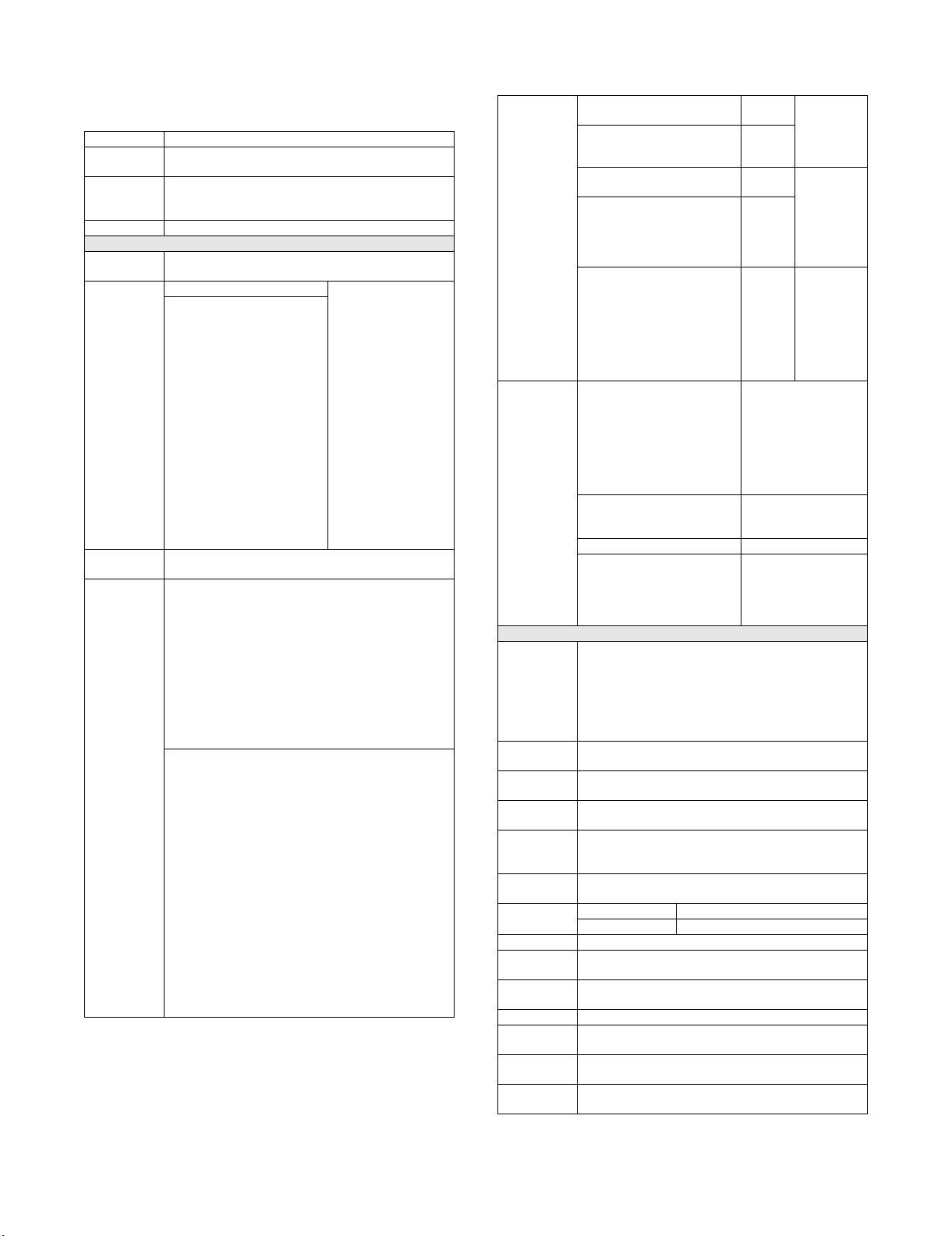
Punch type 2/3-hole,2/3-hole (North America), 2/4-hole,4-hole (wide)
Type Hole location
2-hole
3-hole
*1
A
B
Hole
diameter
2-hole
A:
80±1mm
B:
12±3mm
2-hole:
φ6.5mm
Paper Size
2-hole:
A3, A4,
A4-R, B4,
A5, B5,
B5-R,
11”x1 7” ,
8.5”x14”,
A
A
B
8.5x13.4,
8.5”x13”,
8.5”x11”,
8.5”x11”-R,
5.5x8.5, 8K,
16K, 16K-R
North
America
2-hole
3-hole*1
3-hole
A:
108±1mm
B:
9.5±3mm
2-hole
A:
70±1mm
B:
3-hole:
φ8.0mm
3-hole:
A3, A4,
11”x1 7” ,
8.5”x11”,
8K, 16K
φ8.0mm 3-hole:
A3, A4,
11”x1 7” ,
8.5”x11”
12±3mm
3-hole
A:
108±1mm
B:
9.5±3mm
2-hole:
A3, A4,
A4R, B4,
A5, B5,
B5R, 11x17,
8.5”x11”-R,
8.5”x14”,
8.5x13.4,
8.5”x13”,
8.5x11,
8.5x11R,
5.5x8.5
2-hole
4-hole*2
A
A
A
B
2-hole
A:
80±1mm
B:
12±3mm
4-hole
A:
80±1mm
B:
12±3mm
φ6.5mm 4-hole: A3,
B4, A4, B5,
11x17 ,
8.5x11
2-hole:A3,
A4, A4R,
B4, A5, B5,
B5R,11x17,
8.5x11,
8.5x11R,
8.5x14 ,
8.5x13.4,
8.5x13,
5.5x8.5
4-hole
wide
A
C
A:
70±1mm
B:
12±3mm
C:
21±1mm
φ6.5mm A3, A4,
A4-R, B4,
A5, B5,
B5-R,
11”x1 7” ,
8.5”x14”,
8.5x13.4,
8.5”x13”,
8.5”x11”,
8.5”x11”-R,
5.5x8.5
Adjustment of
Punch
±3mm (Feeding direction), Adjustment pitch 0.5mm,
Controlled by main unit.
Position
B-direction should be manually adjustable.
Punchable
Paper Weight
Manual
Punch
Power
2-hole,2/3-hole :52-176g/m
4-hole,4-hole wide: 52-128g/m
(Operation using the operation panel when the inserter is
installed)
Supplied by the finisher
2
/16lbs Bond-65lb.Cover
2
/16lbs Bond-32lb.Bond
Source
Dimensions
80mm x 500mm x 133mm
( W x D x H )
Weight 3.1kg
*1: Manual (OPE) Switching: 2 holes/3 holes
*2: Manual (OPE) Switching 2-hole/4-hole
*3:Punch and Folding are not able to use simultaneously.
2. 85 sheet model
Form Floor Type
Tran sp ort
speed
Paper
Tran sp ort
standard
Pause Switch Available
Tray Form Top tray Fixed
Paper sizes
allowed
Stored paper
weight (Nonstitched)
Stored sheets Top tray
Stacking
performance
Number of
sheets to be
stitched
Paper weight
to be stitched
Number of
stored sheets
when stapled
(80g/m
Supports 85 sheets/minute
Center alignment
Stacker section
Offset tray Up and down offset tray
Top tray A3W, A4W, A3, B4, A4,
Offset tray
A4-R, B5, B5-R, A5-R,
8K, 16K, 16KR,
Postcard, 11"x17",
8.5"x14", 8.5x13.4,
8.5x13, 8.5"x11",
8.5"x11"-R,
5.5"x8.5"-R, 12"x18",
9"x12", 7.25"x10.5"-R
Top tray: 52 - 205g/m
Offset tray: 52 - 300g/m
2
, 16lbs Bond-110lbs Index
2
, 16lbs Bond-170lbs Index
• 250 sheets: A4, 8.5"x11" or less (80g/m
• 50 sheets: B4, 8.5"x14" or more (80g/m
* A5/5.5x8.5 are feeded from Inserter Tray of Inserter
Unit.
Offset tray
• 3000sheets: A4, 8.5"x11" (80g/m
2
• 1500sheets:
A3W, A4W, A3, B4, A4-R, B5, B5-R, 8K, 16K, 16KR,
12"x18", 11"x17", 8.5"x14", 8.5",x13.4", 8.5"x13",
8.5”x11”-R, 9”x12" (80g/m
• 100 sheets: A5-R*, 5.5"x8.5"-R*, Postcard*
2
(80g/m
, 20lbs Bond)
2
, 20lbs Bond)
* Impossible to Offset.
Non-offset 12 mm or less (B5R
and A5R are 50mm or
less)
Offset 12 mm or less (B5R
and A5R are 50mm or
less)
Offset volume 30 mm
Stitched 3mm or less
Staple section
• 50 sheets: A4, 8.5”x11” or less
• 30 sheets: B4, 8.5"x14" or more
• Mixed (same width):30 sheets
Max. 176g/m
2
(65lbs Index) paper 2 sheets+80g/m2
paper 48 sheets
60 - 105g/m
2
16lbs-28lbs Bond
A4, 8.5x11: 2-19 sheets
150 bundles
2
)
20-50 sheets
150-60 bundles
A4R, B5, 8.5x11R: 2-14 sheets
100 bundles
15-50 sheets
100-30 bundles
Others: 2-14 sheets
100 bundles
15-30 sheets
100-50 bundles
When mixed size:
2-30 sheets 50 bundles
A3 and A4, B4 and B5, 11x17
and 8.5x17
2
, 20lbs Bond)
2
, 20lbs Bond)
, 20lbs Bond)
MX-FNX5 SPECIFICATION 1 – 2
Page 4
Stap le
B
B
4 position (Top, Top Slant, Bottom, 2 Staples)
Position
Stapling
method
Adjustment of
Stap le
Staple cartridge (5,000 staples)
Changeable by user
-1 - +3.5mm (For 1 position staple only), Adjustment pitch
0.5mm, Controlled by main unit.
position
Detection of
Available
no staple
Manual
Stap le
(When the inserter is installed, it can be operated on the
operation panel of the main unit.)
Life 5 year or 9,900K
Dimensions
(W x D x H)
640mm x 614mm x 960mm
745mm x 614mm x 960mm (Tray extended)
Weight 45.9kg
Power
DC24V (supplied by the main unit)
Source
Power
96W (Include Punch module)
Consumption
Punch Module for 50 sheets stapling (Option)*3
Form Built in the finisher
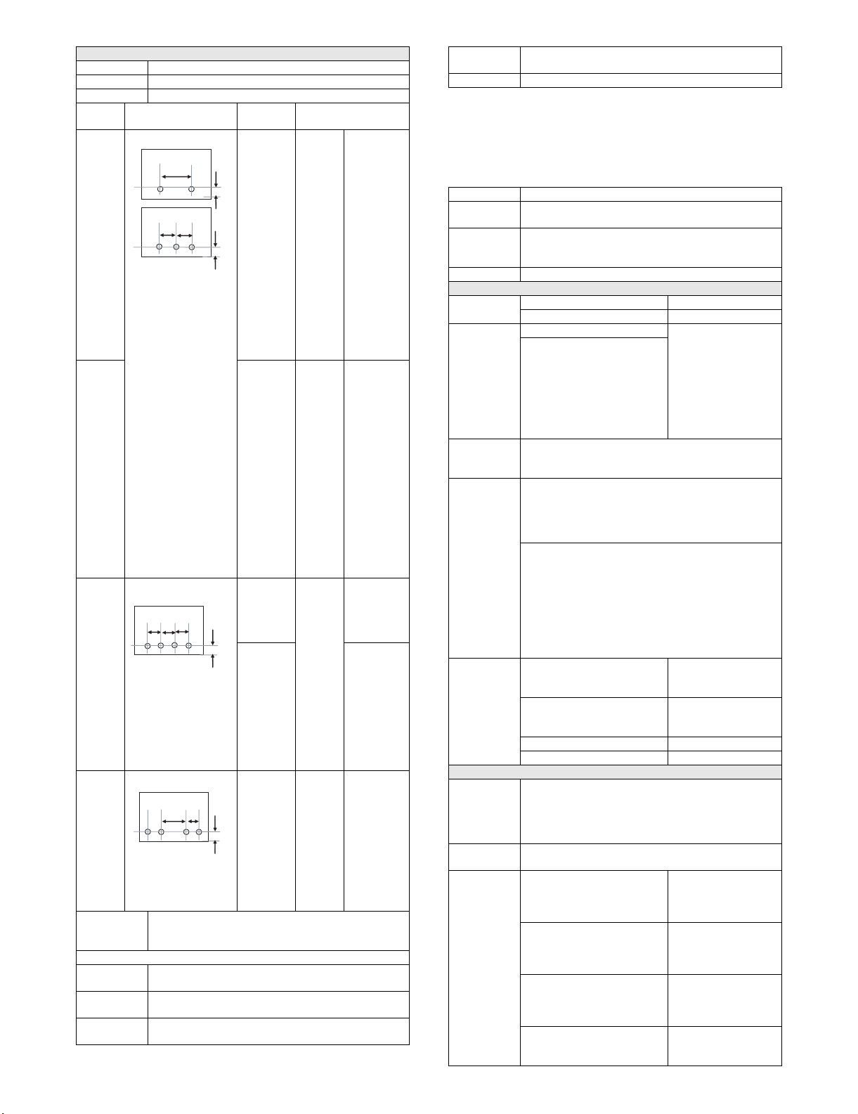
Punch style Reciprocal type
Type Hole location
Hole
diameter
2-hole 2-hole
A:
80±1mm
B:
12±3mm
B
A
A
North
America
2-hole
3-hole*1
B
2-hole
A:
70±1mm
B:
12±3mm
3-hole
A:
108±1mm
B:
9.5±3mm
2-hole
4-hole*2
2-hole
A:
80±1mm
A
A
A
B:
12±3mm
4-hole
A:
80±1mm
B:
12±3mm
B
4-hole
wide
A:
70±1mm
B:
A
C
12±3mm
C:
21±1mm
Adjustment of
Punch
Position
Feeding direction(X): ±3mm, Adjustment pitch 0.5mm,
Control by main unit.
Y direction: ±2mm, Adjustment pitch 0.4mm, Control by
main unit.
Can be manually adjusted in the B direction.
Manual
Punch
Yes (When the inserter is installed, it can be operated on
the operation panel of the main unit.)
Paper Size
2-hole:
φ6.5mm
2-hole:
A3, A4,
A4-R, B4,
B5, B5-R,
11”x1 7” ,
8.5”x14”,
8.5x13.4,
8.5”x13”,
8.5”x11”,
8.5”x11”-R,
8K, 16K,
16K-R
φ8.0mm 3-hole:
A3, A4,
11”x1 7” ,
8.5”x11”
2-hole:
A3, A4,
A4R, B5,
B5R, 11x17,
8.5”x11”-R,
8.5”x14”,
8.5x13.4,
8.5”x13”
φ6.5mm 4-hole: A3,
B4, A4, B5,
11”x1 7” ,
8.5”x11”
2-hole:A3,
A4, A4R,
B5, B5R,
11”x1 7” ,
8.5”x11”-R,
8.5”x14”,
8.5”x13.4”,
8.5”x13”
φ6.5mm A3, A4,
A4-R, B4,
B5, B5-R,
11”x1 7” ,
8.5”x14”,
8.5x13.4,
8.5”x13”,
8.5”x11”,
8.5”x11”-R
Punchable
52-163g/m2, 16lbs Bond
Paper Weight
Power
In the finisher
Source
Dimensions
130mm x 515mm x 140mm
( W x D x H)
Weight 1.4kg
*1: Manual(OPE) Switching: 2 holes/3 holes
*2: Manual(OPE) Switching 2-hole/4-hole
*3: Punch and Folding are not able to use simultaneously.
MX-FNX5 SPECIFICATION 1 – 3
Page 5

3. Tray specification
Top tray Top tray
Minimum paper weight 52g/m
(14lbs
bond)
Maximum paper weight 205g/m
(40lbs
bond)
(110lbs
index)
(65lbs
cover)
Paper
Thin paper Yes
type
(Even
52g/m
possible)
Folding
output
2
60g/m2
(16lbs
bond)
2
105g/m
No Yes
2
is
Offset tray Offset tray
52g/m2
(14lbs
bond)
2
300g/m2
(40lbs
bond)
(140lbs
index)
(100lbs
cover)
(Even
52g/m2 is
possible)
Folding
output
60g/m2
(16lbs
bond)
2
105g/m
No Yes
Punch
(2/3-holes)
J
52g/m2
(14lbs
bond)
176g/m2
(65lbs
cover)
(Even
52g/m2 is
possible)
Punch
(2/3-holes)
NA
52g/m2
(14lbs
bond)
176g/m2
(65lbs
cover)
Ye s
(Even
52g/m2 is
possible)
Punch
(2/4-holes)
52g/m2
(14lbs
bond)
4- holes:
128g/m
2- holes:
176g/m
Yes
(Even
52g/m2 is
possible)
2
2
Punch
(4-holes
52g/m2
128g/m
52g/m2 is
possible)
Plain paper Yes Yes Yes Yes Yes Yes Yes Yes Yes
Recycled paper Yes Yes Yes Yes Yes Yes Yes Yes Yes
Colored paper Yes Yes Yes Yes Yes Yes Yes Yes Yes
Letter head Yes Yes Yes Yes Yes Yes Yes Yes Yes
Pre-printed paper Yes Yes Yes Yes Yes Yes Yes Yes Yes
Pre-punched paper Yes Yes Yes Yes No No No No Yes
Finisher (For 100 sheets staple)
Heavy paper1
(106-128g/m
Heavy paper2
(129-176g/m
Heavy paper3
(177-205g/m
Heavy paper4
(206-300g/m
2
)
2
)
2
)
2
)
Yes No Yes No Yes Yes Yes Yes Yes*1
Yes No Yes No Yes Yes Yes No Yes*1
Yes No Yes No No No No No Yes
NoNoYesNoNoNoNoNoNo
Tab paper Yes No Yes No Yes Yes Yes Yes Yes
Transparency
YesNoNoNoNoNoNoNoNo
paper
Label paper Yes No No No No No No No No
Paper
size
12”x18”
(A3W)
Ledger
(11”x17”)
Ledger
(11”x17”)
305
x457
279
x432
279
x216
Yes Yes Yes Yes No No No No No
YesYesYesYesYesYesYesYes Yes
Yes Yes Yes Yes No No No No Yes
Zfolding
Legal
(8.5”x14”)
Legal
(8.5”x14”)
216
x356
216
x178
YesYesYesYesyes
(2-holes)
yes
(2 -holes)
yes
(2 -holes)
Yes Yes Yes Yes No No No No No
Z folding
Mexican
Legal
216
x340
Yes No Yes No yes
(2-holes)
yes
(2-holes)
yes
(2-holes)
(8.5”
x13.4”)
Foolscap
( 8.5'x13')
Letter
(8.5”x11”)
Letter R
(8.5”x11”R)
Letter R
(8.5”x11”R)
216
x330
279
x216
216
x279
216
x140
Yes No Yes No yes
(2-holes)
yes
(2-holes)
yes
(2-holes)
Yes No Yes No Yes Yes Yes Yes Yes
YesYesYesYesyes
(2-holes)
yes
(2-holes)
yes
(2-holes)
Yes Yes Yes Yes No No No No No
Z folding
Invoice
(5.5” x8.5”)
Invoice R
(5.5”
216
x140
140
x216
Yes-Yes-yes
(2-holes)
yes
(2-holes)
yes
(2-holes)
Yes No Yes No No No No No No
x8.5”R)
Exective R
(7.25”
184
x266
Yes No Yes No No No No No Yes
x10.5”)
9x12
(A4W)
A3 297
305
x229
Yes No Yes No No No No No No
YesYesYesYesYesYesYesYes Yes
x420
wide)
60g/m2
(14lbs
bond)
2
105g/m2
As for the
sheet, Even
205g/m
possible
Ye s
(Even
Ye s Ye s
Ye s Ye s
Ye s Ye s
Ye s Ye s
Ye s N o
At the
staple
(16lbs
bond)
(28lbs
bond)
cover
No
2
is
MX-FNX5 SPECIFICATION 1 – 4
Page 6

Paper
A3
size
Z folding
B4 257
B4
Z folding
A4 297
A4-R 210
A4-R
Z folding
B5 257
B5 -R 182
A5 210
A5-R 148
SRA3 320
SRA4 320
318x234.75mm Yes No Yes No No No No No No
312.5x220mm Yes No Yes No No No No No No
318x469.5mm Yes No Yes No No No No No No
312.5x440mm Yes No Yes No No No No No No
8K 270
16K 270
16K-R 195
Postcard 100
Special-Custom
size
(Custom
Range)
Special-Size
uncertain
297
x210
x364
257
x182
x210
x297
210
x148
x182
x257
x148
x210
x450
x225
x390
x195
x270
x148
min
Main
max
Main
min
Sub
max
Sub
*1: Cover and back cover only
Top tray Top tray
Folding
output
Yes Yes Yes Yes No No No No Yes
YesYesYesYesyes
Yes Yes Yes Yes No No No No Yes
Yes No Yes No Yes Yes Yes Yes Yes
YesYesYesYesyes
Yes Yes Yes Yes No No No No No
Yes No Yes No yes
Yes No Yes No yes
Yes-Yes-yes
Yes No Yes No No No No No No
Yes No Yes No No No No No No
Yes No Yes No No No No No No
Yes No Yes No Yes Yes Yes Yes Yes
Yes No Yes No Yes Yes Yes Yes Yes
Yes No Yes No yes
YesNoNoNoNoNoNoNoNo
Yes - yes
100 (4.0) - 140 (5.5) - - - - - -
320 (12.5) - 320 (12.5) - - - - - -
140 (5.5) - 140 (5.5) - - - - - -
470 (18.5) - 470 (18.5) - - - - - -
Yes - No - NoNoNoNoNo
Offset tray Offset tray
(Impossible
to Offset)
Finisher (For 100 sheets staple)
Folding
output
- NoNoNoNo No
Punch
(2/3-holes)
J
(2-holes)
(2-holes)
(2-holes)
(2-holes)
(2-holes)
(2-holes)
Punch
(2/3-holes)
NA
yes
(2-holes)
yes
(2-holes)
yes
(2-holes)
yes
(2-holes)
yes
(2-holes)
yes
(2-holes)
Punch
(2/4-holes)
Yes Ye s Ye s
yes
(2-holes)
Yes Ye s Ye s
yes
(2-holes)
yes
(2-holes)
yes
(2-holes)
Punch
(4-holes
wide)
Ye s Ye s
Ye s Ye s
Ye s N o
Ye s Ye s
At the
staple
MX-FNX5 SPECIFICATION 1 – 5
Page 7
:07’.07.27
1
MX-FNX5
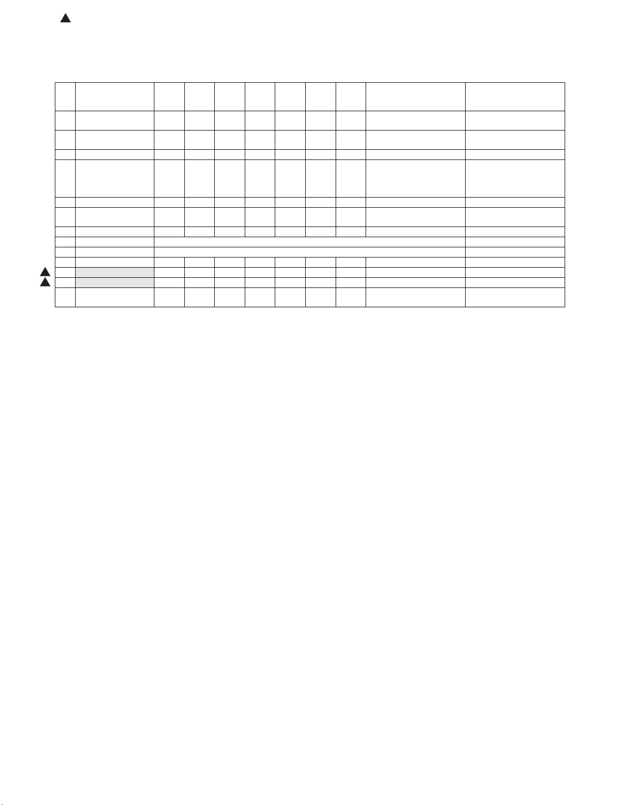
[2] MAINTENANCE LIST
✕: Check {: Clean S: Replace U: Adjust ✩: Lubricate : Shift position
(Clean, replace, or adjust as needed.)
Service Manual
No. Part name
1 Transport rollers ✕ {{{{{{ When there is dirt, wipe with
2 Transport paper
guides
3 Gears ✕✕✕✕✕✕✕ UKOG-0307FCZZ
4 Discharge brush ✕✕✕✕✕✕✕ When there is dirt, wipe
5 Brush roller ✕✕✕✕✕S ✕
6 Sintered bearing ✕✕✕✕✕✕✕Lubricate when an abnormal
7 Sensor ✕ {{{{{{ Clean by air
8 Stapler Replacement reference: Replace the unit after 500K of staple.
9 Punch (Option) Replacement reference: Replace the unit after 1,000K of punch.
10 Cut needle ✕✕✕✕✕✕✕ Collect cut needles.
11
1
1
Positioning roller ✕✕✕✕✕S ✕
Drag roller ✕ SSSSSS
12
13 Jogger slide part ✩✩✩✩✩✩ Silicon oil :
When
calling
500K 1000K 1500K 2000K 2500K 3000K Life judgement (Reference)
✕ {{{{{{ When there is dirt, wipe with
sound is heard.
Tool, oil, chemicals
Procedure
Treatment after procedure
wet cloth with water.
wet cloth with water.
brush part with wet cloth with
water.
* Refer to the NOTE:
Tellus oil : 0CW4110K701//
ZSOLVZZL006FC
NOTE: Discharge brush cleaning
Wipe the brush with wet cloth with a small amount of water. (Recommend)
Handle the brush carefully.
MX-FNX5 MAINTENANCE LIST 2 – 1
Page 8
[A]
[B]
[C]
MX-FNX5
[3] REPLACEMENT AND ADJUSTMENT
Service Manual
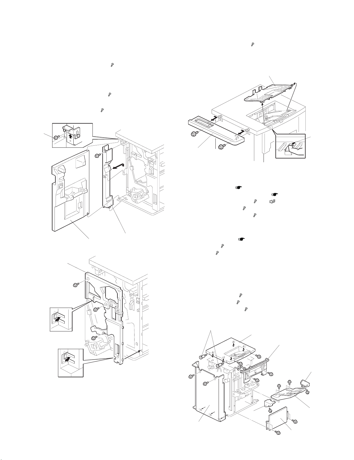
1. COVERS
A. FRONT DOOR, INNER COVER
(1) Front Door
1) Remove the front door screw [A] ( x 1).
2) Remove the front door [B].
(2) Left Inner Cover
1) Remove the front door.
2) Remove the left inner cover [C] ( x 1).
(3) Inner Cover
1) Remove the inner cover [D] ( x 3).
[A]
[B]
[D]
[C]
B. SIDE TABLE AND UPPER TRAY
1) Remove the side table [A] ( x 2). Slide to the right to remove
it.
2) Click the release lever [B] and remove the upper tray [C].
C. LEFT COVERS, REAR COVER
Remove:
• Shift tray jogger unit ( 8. SHIFT TRAY JOGGER UNIT -A.)
• Remove the door and left inner cover. ( 1. COVERS -A.)
[A] Remove the left upper cover ( x 2, x 2).
[B] Remove the rear cover ( x 2).
[C] Remove the left lower cover ( x 4).
D. TOP COVER
Remove:
• Side table, upper tray ( 1. COVERS -B.)
[D] Step screws ( x 2).
[E] Top cover ( x 2). Slide to the right to remove.
E. SHIFT TRAY
• If you need to lower the shift tray, support the bottom of the tray
with your hand, then pull the gear toward you (1) to release the
tray and lower it.
Remove:
[F] Remove the shift tray ( x 4).
[G] Shift tray rear cover ( x 1)
[H] Shift tray front cover [H] ( x 1).
[D]
[B]
MX-FNX5 REPLACEMENT AND ADJUSTMENT 3 – 1
[G]
[E]
[A]
[H]
[F]
[C]
Page 9
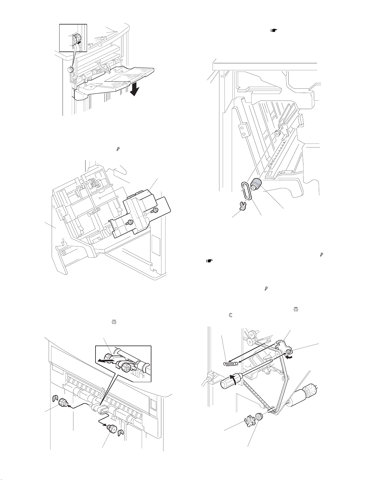
(1)
F. JOGGER UNIT COVER
1) Open the front door.
2) Pull out the stapler tray unit [A].
3) Remove the jogger unit cover [B] ( x2)
B. POSITIONING ROLLER
1) Remove the jogger unit cover ( 1. COVERS -F.)
2) Remove the snap ring [A].
3) Release the rubber belt [B].
4) Replace the positioning roller [C].
[B]
[A]
2. ROLLERS
A. DRAG ROLLER
1) Above the shift tray, pull the roller mount [A] out.
2) Remove the rollers [B] and [C] ( x 1 each)
[A]
[A]
[B]
C. ALIGNMENT BRUSH ROLLER
[C]
1) Open the front door and pull out the staple unit.
2) Remove the rear cover.
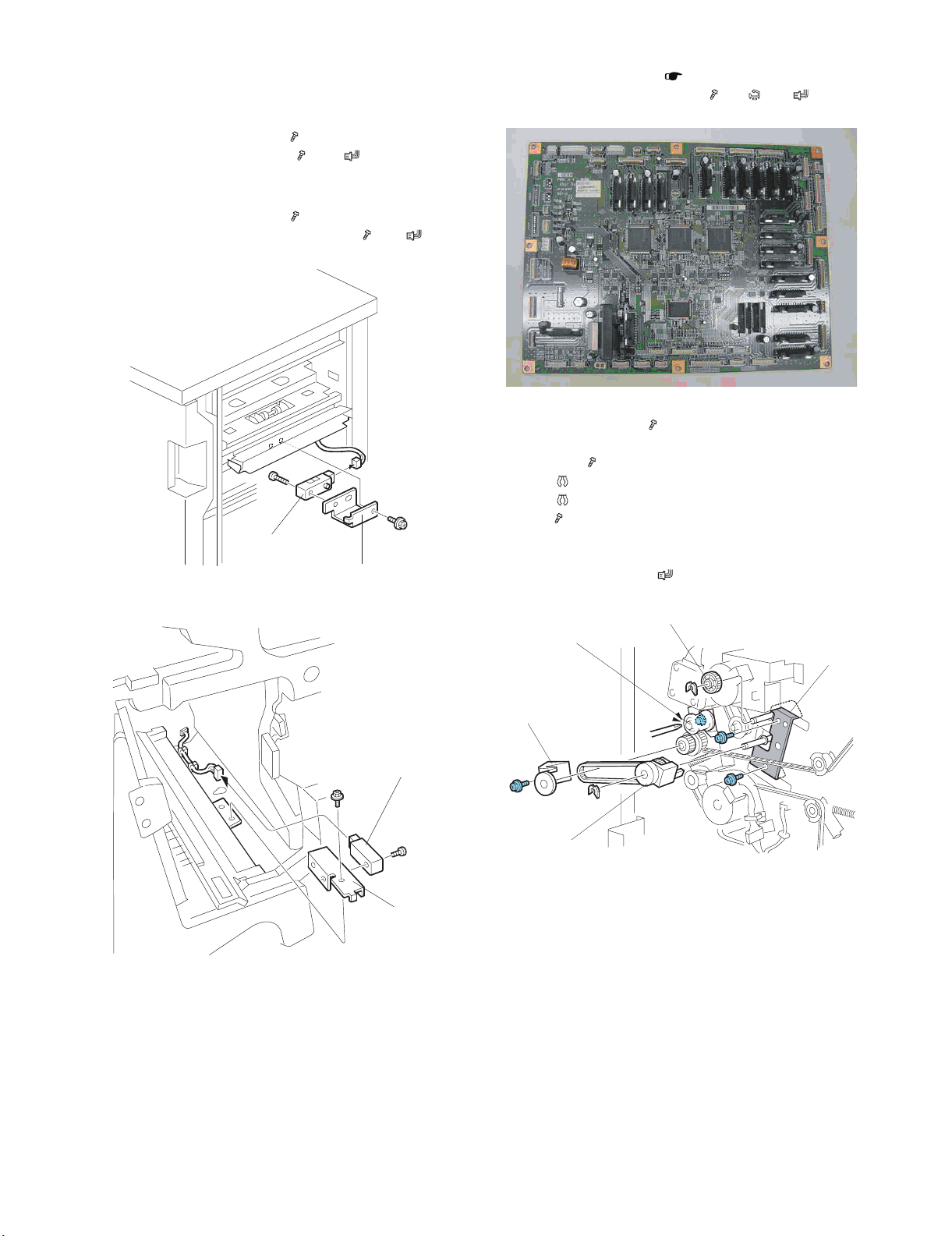
3) Remove the main board bracket and all connectors ( x 8).
( 4. SENSORS -F.)
4) Remove the screw [A] and tension spring [B] for the tension
bracket [C], and release the tension of the timing belt.
5) Remove the pulley [D] and bearing [E].
6) Remove the inner cover [F] ( x 1).
7) Open the guide [G], then remove the alignment brush roller
assembly [H].
8) Remove the alignment brush roller [I] ( x2, Bearing x 1
front/back, x1).
[B]
[C]
[A]
[B]
[C]
[D]
[E]
MX-FNX5 REPLACEMENT AND ADJUSTMENT 3 – 2
Page 10
[H]
[G]
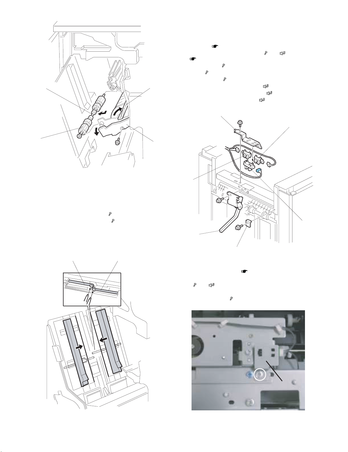
4. SENSORS
A. PAPER HEIGHT SENSORS
Remove:
• Top cover. ( 1. COVERS -D.)
• Left upper panel and left upper cover ( x 2, x 2)
( 1. COVERS -C.)
[A] Protector plate ( x 1).
[B] Feeler ( x 1).
[C] Sensor bracket ( x 1).
[D] Paper height sensor - staple mode ( x 1, Pawls x4)
[E] Paper height sensor - standby mode ( x 1, Pawls x4)
[F] Paper height sensor - shift/Z-Fold( x 1, Pawls x4).
[C]
[D]
[I]
3. JOGGER FENCE
1) Open the front door.
2) Pull out the jogger and stapler unit.
3) Push both fences to the center.
4) Remove the left jogger fence [A] ( x 1)
5) Remove the right jogger fence [B] ( x 1).
NOTE:
If the screws are difficult to remove or re-attach, remove the
jogger fence belt and spring plate.
[B] [A]
[F]
[F]
[E]
[B]
[A]
B. EXIT GUIDE HP SENSOR
1) Remove the top cover. ( 1. COVERS -D.)
2) Remove the left upper panel and left upper cover
( x 2, x 2).
Remove:
[A] Sensor bracket [A] ( x 1).
MX-FNX5 REPLACEMENT AND ADJUSTMENT 3 – 3
[A]
Page 11
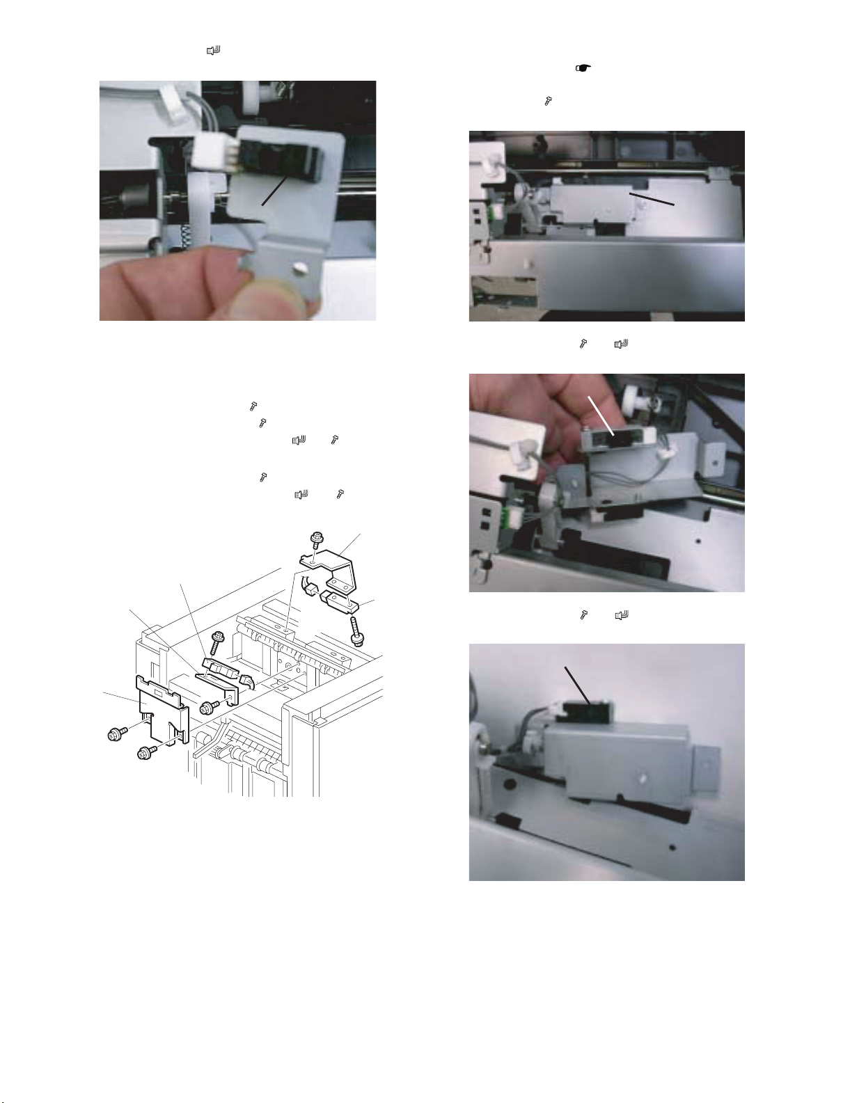
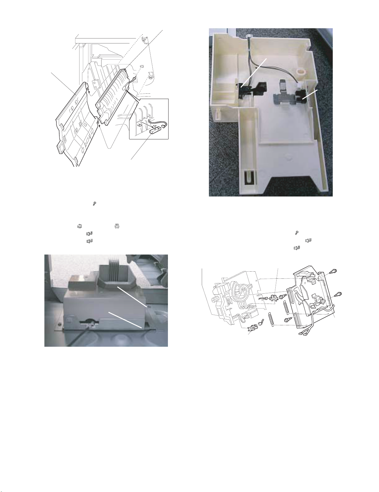
[B] Exit guide HP sensor ( x 1, Pawls x3).
D. SHIFT TRAY EXIT SENSOR
• Remove the top cover ( 1. COVERS -D.)
Remove:
[A] Sensor bracket ( x1)
[B]
C. UPPER TRAY FULL AND EXIT SENSORS
(1) Upper Tray Full Sensor
1) Remove the top cover.
2) Remove the sensor cover [A] ( x 2).
3) Remove the sensor bracket [B] ( x 1).
4) Replace the upper tray full sensor [C] ( x1, x 1).
(2) Upper Tray Exit Sensor
1) Remove the sensor bracket [D] ( x 1).
2) Replace the upper tray exit sensor [E] ( x 1, x 1).
[C]
[B]
[A]
[B] Shift tray exit sensor 1 ( x1, x1)
[B]
[D]
[E]
[C] Shift tray exit sensor 2 ( x1, x1)
[A]
[C]
MX-FNX5 REPLACEMENT AND ADJUSTMENT 3 – 4
Page 12
E. ENTRANCE AND STAPLER TRAY ENTRANCE
[A]
[B]
[C]
[D]
[E]
SENSORS
(1) Entrance Sensor
1) Disconnect the finisher from the copier.
2) Remove the sensor bracket [A] ( x 1).
3) Replace the entrance sensor [B] ( x 1) ( x 1).
(2) Stapler Tray Entrance Sensor
1) Open the front door.
2) Remove the sensor bracket [C] ( x 1).
3) Replace the stapler tray entrance sensor [D] ( x 1)( x 1).
[B]
[A]
F. MAIN BOARD, PRE-STACK PAPER SENSOR
1) Remove the rear cover. ( 1. COVERS -D.)
2) Remove the main board bracket ( x6, x8, x All).
3) Open the front door.
4) Loosen the screw [A] ( x1)
Remove:
[B] Gear cover ( x1)
[C] Gear ( x1, Timing belt x1)
[D] Gear ( x1)
[E] Plate ( x2)
[F] Left vertical transport guide
[G] Middle vertical transport guide
[H] Pre-stack paper sensor ( x1)
[D]
[C]
MX-FNX5 REPLACEMENT AND ADJUSTMENT 3 – 5
Page 13
[G]
[A]
[C]
[B]
[F]
[H]
G. STAPLE TRIMMINGS HOPPER FULL SENSOR
• Open the front door
• Pull out the stapler unit
• Remove the rear cover ( x 2).
Remove:
[A] Staple trimmings hopper
[B] Hopper holder ( x1, Hook x1, x1)
[C] Hopper full sensor ( x 1)
[D] Hopper set sensor ( x 1)
[D]
[C]
H. STAPLER ROTATION HP AND STAPLER
RETURN SENSORS
1) Remove the stapler unit. (See next page.)
2) Remove the stapler mount bracket [A] ( x 4) (Springs x 2).
3) Replace the stapler rotation HP sensor [B] ( x 1).
4) Replace the stapler return sensor [C] ( x 1).
[A]
[B]
MX-FNX5 REPLACEMENT AND ADJUSTMENT 3 – 6
Page 14
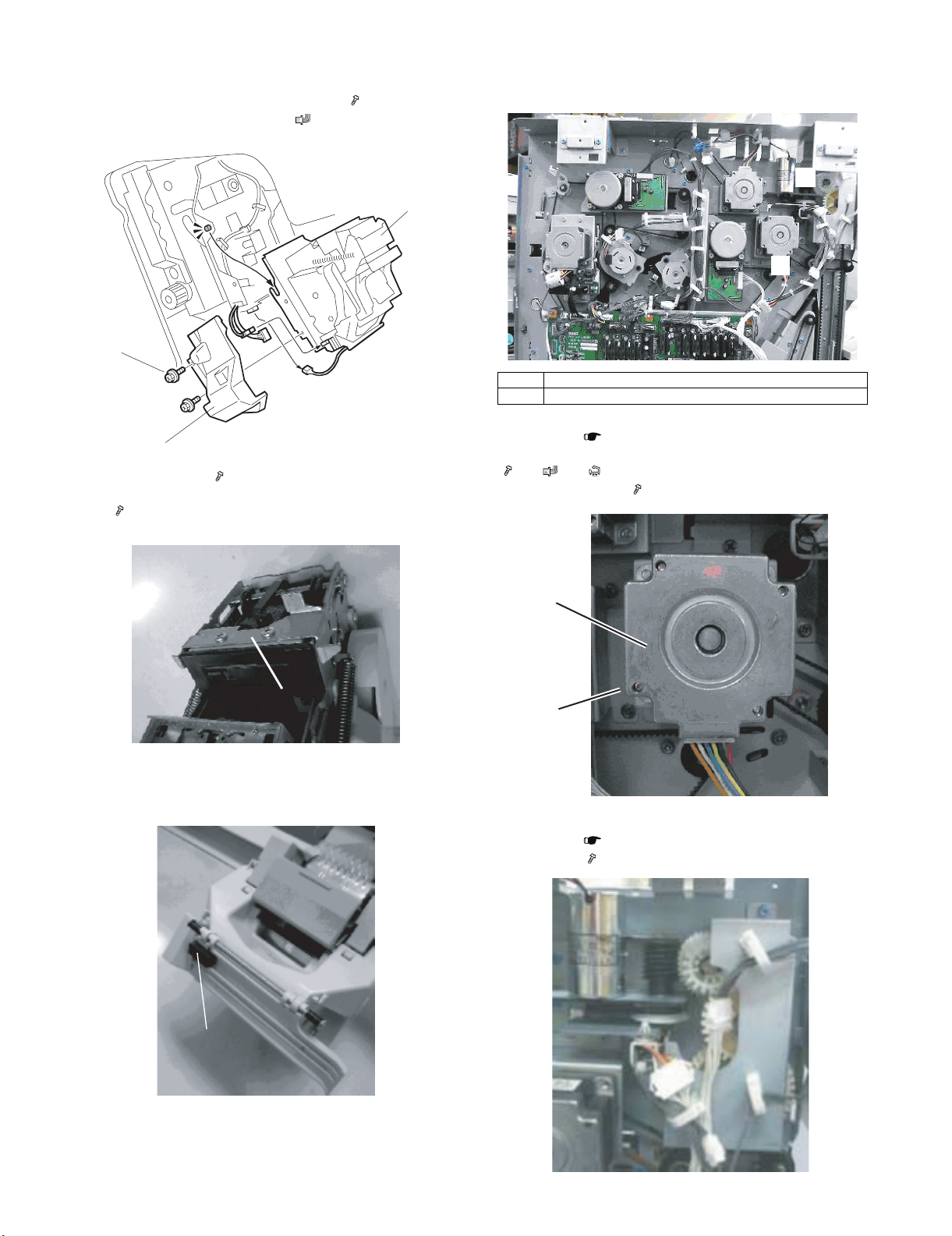
5. STAPLER
1) Open the front door and pull out the staple tray.
2) Remove the stapler unit harness cover [A] ( x 2).
3) Lift the stapler [B] off of its pegs ( x 2)
[B]
[A]
4) Remove plate [C] ( x 2).
5) Attach this plate to the new stapler with the same screws
( x 2).
6. SHIFT TRAY
A. SHIFT TRAY EXIT, SHIFT TRAY LIFT MOTOR
(2)
(1)
(1) Shift Tray Exit Motor
(2) Shift Tray Lift Motor
(1) Shift Tray Exit Motor
• Rear cover ( 1. COVERS -D.)
[A] Shift tray exit motor bracket
( x2, x1, X1, Timing belt x1)
[B] Shift tray exit motor ( x2)
[C]
6) Replace the frame guard [D] with the one provided with the
new stapler.
[D]
[B]
[A]
(2) Shift Tray Lift Motor
• Rear cover ( 1. COVERS -D.)
[A] Gear cover ( x2)
[A]
MX-FNX5 REPLACEMENT AND ADJUSTMENT 3 – 7
Page 15
[B] Shift tray lift motor bracket ( x2)
[A]
[B]
[C]
[D]
[C] Shift tray lift motor ( x2, x1, Timing belt x1)
[B]
[C]
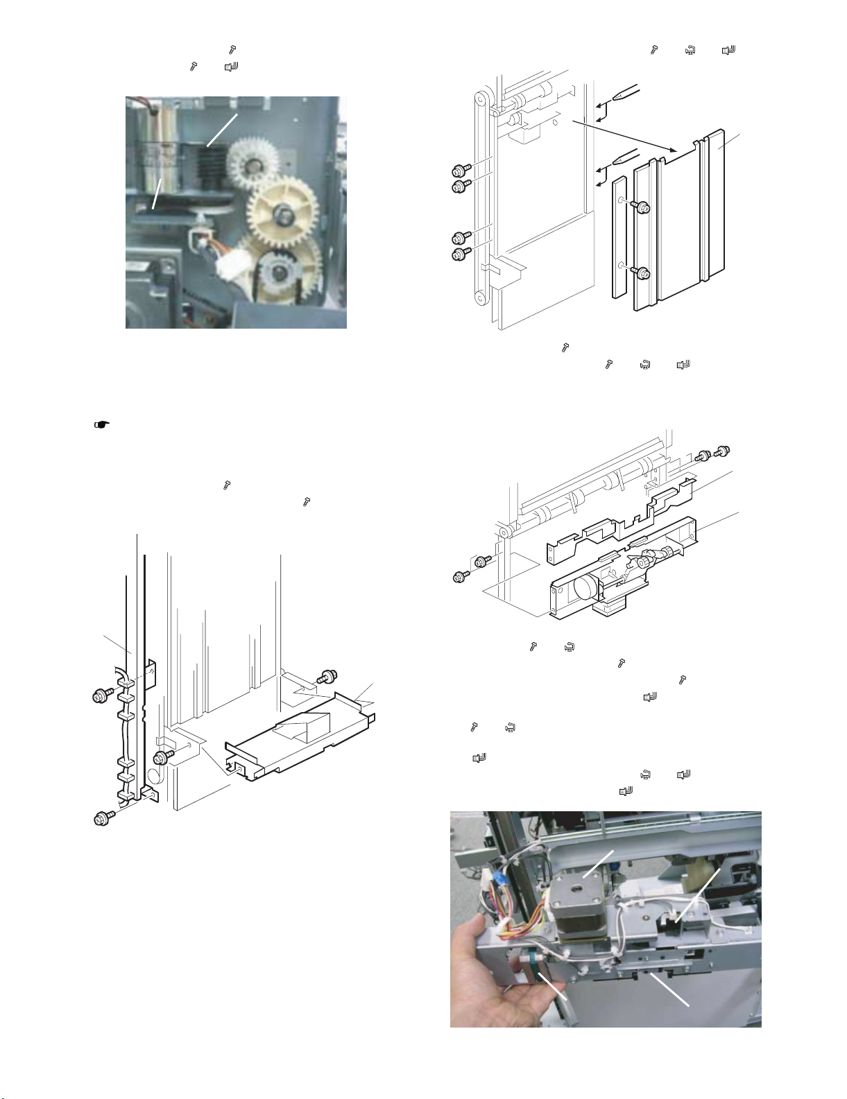
3) Remove the end fence [A] and plate ( x8, x6, x2).
[A]
B. DRAG ROLLER/DRAG DRIVE MOTORS, DRAG
DRIVE HP SENSOR
Remove:
• Front door and all covers, except the left lower cover, top cover
( 1. COVERS)
NOTE:
Be sure to lower the shift tray by pulling the gear toward you. The
shift tray must be down.
1) Remove the left stay [A] ( x 2)
2) Remove the shift tray mounting plate [B] ( x 2).
[A]
[B]
4) Remove cover [B] ( x 4).
5) Remove the motor stay [C] ( x4, x7, x4).
NOTE:
Make sure the motor and sensor connectors are disconnected
before removing.
[B]
[C]
6) Remove the drag roller motor unit [A]
(Bearing x1, x2, x1)
7) Remove the drag roller motor ( x2)
8) Remove the drag roller HP sensor unit [B] ( x1)
9) Remove the drag roller HP sensor ( x1, Pawls x3)
10) Remove the paper height sensor - shift/Z-fold unit [C]
( x2, x2)
11) Remove the paper height sensor shift/Z-fold
( x1, Pawls x3)
12) Remove the drag drive motor unit ( x4, x2)
13) Remove the drag drive motor ( x2)
MX-FNX5 REPLACEMENT AND ADJUSTMENT 3 – 8
Page 16

C. SHIFT MOTOR AND SENSORS
1) Remove the end fence ( 6. SHIFT TRAY -B.)
2) Remove the shift motor bracket [A] (with motor)
( x 4, x1, x1)
[A]
E. JOGGER UNIT
1) Open the front door and pull out the stapler tray unit.
2) Remove the jogger unit cover ( x2)
3) Remove the jogger unit [A] ( x4, x5, x5)
3) Remove the shift motor ( x4)
4) Remove the half-turn sensor bracket [B] ( x 1)
5) Remove half-turn sensor 1 [C] ( x1, Pawls x3)
6) Remove half-turn sensor 2 [D] ( x1, Pawls x3)
[C]
[B]
[D]
D. JOGGER TOP FENCE MOTOR
1) Open the front door and pull out the stapler tray unit.
( 1. COVERS -F.)
2) Remove the jogger unit cover ( x2)
3) Remove the motor bracket [A] ( x2, timing belt x1)
4) Remove the jogger top fence motor [B] ( x2 x1 x1)
[A]
F. JOGGER BOTTOM FENCE MOTOR
1) Open the front door and pull out the stapler tray unit.
2) Remove the jogger bottom fence motor unit [A]
( x3, timing belt x1, x1, x1).
[A]
[A]
[B]
MX-FNX5 REPLACEMENT AND ADJUSTMENT 3 – 9
Page 17

7. PUNCH UNIT
[A]
A. PUNCH POSITION ADJUSTMENT
• The position of the punched holes can be adjusted in two ways.
(1) Front to Rear Adjustment
Three spacers [A] are provided with the punch unit for manual
adjustment of the hole position in the main scan direction:
•2 mm (x 1)
•1 mm (x 2)
NOTE:
One spacer was installed at installation and the remaining spacers were fastened with a screw to the rear frame of the finisher
under the rear cover and slightly above the lock bar.
[A]
2) Remove the jogger unit [B] ( x 2, x 1).
[B]
B. SHIFT TRAY JOGGER UNIT PCB
1) Remove the jogger unit from the finisher. ( 8. SHIFT
TRAY JOGGER UNIT -A.)
2) Remove the jogger unit control PCB [A] ( x 2, x 3)
8. SHIFT TRAY JOGGER UNIT
A. SHIFT TRAY JOGGER UNIT
1) Remove the jogger unit cover [A] ( x 2).
*Apply grease
* Apply grease to the jogger slide part at every 500K.
(Silicon oil : ZSOLVZZL006FC)
[A]
C. SHIFT TRAY JOGGER UNIT MOTORS
1) Remove the jogger unit from the finisher. ( 8. SHIFT
TRAY JOGGER UNIT -A.)
2) Remove the shift tray jogger motor [A] ( x 2, x 1).
3) Remove the shift tray jogger retraction motor [B]
( x 2, x 1).
[A]
MX-FNX5 REPLACEMENT AND ADJUSTMENT 3 – 10
[B]
Page 18

9. MOTORS
(1)
(2)
A. TRANSPORT MOTORS, EXIT GUIDE MOTOR
(1)
(2)
(1) Upper Transport Motor
(2) Lower Transport Motor
(1) Upper Tray Transport Motor
• Rear cover ( 1. COVERS -D.)
[A] Upper transport motor ( x4, x1)
(3) Exit Guide Motor
• Top cover ( 1. COVERS -D.)
[A] Bracket ( x2, x1)
[A]
[B] Exit guide motor ( x2, x1, Timing belt x1)
[B]
[A]
(2) Lower Transport Motor
• Rear cover ( 1. COVERS -D.)
[A] Lower transport motor ( x4, x1)
[A]
B. UPPER TRAY MOTORS
(1) Upper Tray Exit Motor
(2) Upper Tray Junction Gate Motor
MX-FNX5 REPLACEMENT AND ADJUSTMENT 3 – 11
Page 19

(1) Upper Tray Exit Motor
[A]
• Rear cover ( 1. COVERS -D.)
[A] Motor bracket ( x2, x1)
[B] Upper tray exit motor ( x2, Timing belt x1)
(1) Pre-Stack Transport Motor
• Rear cover (1. COVERS -D.)
• Main control board bracket ( x4, x All, x8)
• Motor unit ( x2, x1)
[A] Pre-stack transport motor ( x2)
[B]
(2) Upper Tray Junction Gate Motor
• Rear cover ( 1. COVERS -D.)
[A] Upper tray junction gate motor ( x2, x1)
[A]
[A]
[A]
(2) Pre-Stack Junction Gate Motor
• Rear cover ( 1. COVERS -D.)
• Main control board bracket ( x4, x All, x8)
[A] Pre-stack junction gate motor ( x2, x1, x1)
C. PRE-STACK MOTORS
(1)
(2)
(3)
• The photograph above shows the main control board removed
( x4, x All).
(1) Pre-Stack Transport Motor
(2) Pre-Stack Junction Gate Motor
(3) Pre-Stack Stopper Motor
MX-FNX5 REPLACEMENT AND ADJUSTMENT 3 – 12
(3) Pre-Stack Stopper Motor
• Rear cover ( 1. COVERS -D.)
• Main control board bracket ( x4, x All, x8)
[A] Pre-stack stopper motor ( x2, x1, x1)
[B]
[A]
Page 20

D. PUNCH MOTOR
(1)
(1) Punch Motor
(1) Punch Motor
• Rear cover ( 1. COVERS -D.)
[A] Punch motor bracket ( x3, x2, x1, Timing belt x1)
[B] Punch motor ( x2)
(1) Staple Junction Gate Motor
• Rear cover ( 1. COVERS -D.)
[A] Staple junction gate motor ( x2, x1, x1)
[A]
(2) Stapler Exit Motor
E. STAPLE MOTORS
[A]
(1)
[B]
(1) Stapler Exit Motor
• Main control board bracket ( x4, x 8, x All)
• Remove the stapler exit motor (1) ( x2 (a), (b), x2, Timing
belt x1)
(1)
(1) Staple Junction Gate Motor
(a)
(b)
MX-FNX5 REPLACEMENT AND ADJUSTMENT 3 – 13
Page 21

Default state
SW101
(Note) Make sure to set as below.
SW101
When limiting the maximum load.
ON
1234
ON
1234
Default state
SW101
(Note) Make sure to set as below.
SW101
When limiting the maximum load.
ON
1234
ON
1234
MX-FNX5
[4] SERVICE TABLES
Service Manual
1. HORIZONTAL RESIST ADJUSTMENT
* If there is virtually no shift, this adjustment is not required. (Basi-
cally this adjustment is not performed in the market.)
When executing the horizontal resist adjustment, remove and shift
the screw which fixes the horizontal resist reference bracket and
turn the reference bracket 90 degrees. Then the whole connection
bracket can be slid horizontally.
Integrated-type connection bracket
Main unit side
Slide
* There is a marking of 2mm pitch in the fixing section on the left
upper side of the connection bracket. The bracket can be shifted
by max. ±5mm.
Loosen the screw and shift
1) Take off the rear cover.
2) Confirm that the power of the connected machine is turned off,
and set the DIP SW101 of the finisher control PWB as below.
B. Loading capacity limitation in the staple mode
(Usage)
• Enable only in the staple mode (The loading capacity in the nonstaple mode is not affected.)
• For A4, A4R, B5, B5R, 8.5" x 11", and 8.5" x 11"R sizes, enable
only when the number of binding sheets is 2 - 15. (This setting is
disabled when the number of binding sheets is 16 - 100.)
• By enabling the setting, about 3,000 sheets can be loaded.
(By the default setting, full stop at the intermediate position
(about 1,200 - 1,800 sheets)).
1) Take off the rear cover.
2) Confirm that the power of the connected machine is turned off,
and set the DIP SW101 of the finisher control PWB as below.
Rotate the bracket
90 degrees.
Normal position of the
horizontal resist reference bracket
a. When paper is on the front side:
Slide the connection bracket to the front side, and shift the center
binding unit to the front side.
b. When paper is on the back side:
Slide the connection bracket to the back side, and shift the center
binding unit to the back side.
2. LIMITATION OF THE MAXIMUM LOAD OF THE COPY RECEIVING TRAY
A. Loading capacity limitation in the non-staple
mode
(Usage)
• Applicable to non-staple mode only. (It does not affect the maxi-
mum load of staple mode.)
• Applicable to A4, B5 and 8.5 x 11 sizes only. (Applicable only to
the 3,000-sheet capable sizes)
• If the paper on the tray has a large amount of curl, the paper may
drop off the tray or a delivery jam may occur. To prevent drop of
paper and delivery jam, it is possible to alter the tray output to
half the maximum specification (About 1,500 to 1,800 sheets).
* To enable both of the above settings A and B (loading setting),
set the DIP SW101 as shown below.
ON
1234
(Note) Do not set to other than
the above.
SW101
MX-FNX5 SERVICE TABLES 4 – 1
Page 22

3. CHECK AND ADJUSTMENT AFTER INSTALLATION OF THE MX-FNX5
(Note)
After installation of the MX-FNX5, be sure to check the off-center
and skew.
If there is any problem in the off-center and skew, a paper jam or
misalignment of the finisher may be produced.
Off-center and skew
The paper feed path is extremely long when all the post-processing
feed options are installed. In such a long path, the cumulative effect
of paper skew and deviation in side-to-side registration may require
adjustment.
Skew appears when the paper rotates away from the direction of
paper feed. If side-to-side registration shifts, the sheet remains
straight but shifts left or right.
(2) Skew adjustment procedures
1) Remove the spacer which is fixed to the MX-FNX5 with two
screws.
2) Insert the spacer into the connection bracket of the MX-FNX5
and adjust.
Spacer
1pc: 2mm
Skew
Side-to-Side Registration Shift
Feed
Direction
A. When the MX-PNX3 (punch unit) is installed to
the MX-FNX5
(1) Skew check
1) Select a punch mode (3-hole or 4-hole) on the operation panel,
and make a copy.
(Setting conditions)
Paper : Use 11 x 17 or A3 paper
Paper feed tray : Paper is fed from the main unit No. 3 tray
* When, however, the MX-MFX1 (manual paper feed unit) is
installed, paper is fed from the MX-MFX1.
2) Measure and check the punch hole positions on the paper.
B
D
3) When dimension A is smaller than dimension B, insert the
spacer in the front side (F) of the connection bracket.
Paper exit
direction
[E]
[C]
[D]
AB
[F]
Holes
Paper exit direction
C
A
3) Check to confirm that the difference between dimension A and
dimension B is within ±2mm.
4) If the difference between dimension A and dimension B is
greater than ±2mm, an adjustment for skew is required.
MX-FNX5 SERVICE TABLES 4 – 2
4) When dimension A is greater than dimension B, insert the
spacer in the rear side (E) of the connection bracket.
Paper exit
direction
[E]
[C]
B
[D]
A
[F]
Page 23

5) Loosen screws (x2) [C] or [D] where the adjustment is required
so the spacer can be inserted.
6) Insert one spacer [E] or [F].
7) Do some more test prints to check the adjustment.
If skew is still present, insert another spacer at the same location.
[E]
[C]
(4) Off-center adjustment procedures
Important
This adjustment can be done on the left side of the copier, at the
MX-FDX1, at the MX-CFX2 at the MX-FNX8.
1) Slide the connection bracket of the FNX5 and adjust.
[B]
Scale: 2 mm
[D]
1
[D]
[F]
(3) Off-center check procedures
1) Select a punch mode (3-hole or 4-hole) on the operation panel,
and make a copy.
(Setting conditions)
Paper : Use 11 x 17 or A3 paper
Paper feed tray : Paper is fed from the main unit No. 3 tray.
* When, however, the MX-MFX1 (manual paper feed unit) is
installed, paper is fed from the MX-MFX1.
2) Measure and check the punch hole positions on the paper.
B
D
Holes
Paper exit direction
C
A
3) Check to confirm that the difference between dimension C and
dimension D is within ±2mm.
4) If the difference between dimension C and dimension D is
greater than ±2mm, the off-center adjustment is required.
3
2
[C]
4
[A]
2) Loosen screws. (1. 2 .3 .4)
3) Remove the bracket [A] (-x1), rotate it 90 degrees, then refasten it.
NOTE:
Re-positioning the bracket aligns the oval cut-out horizontally
so that you can slide the joint bracket to slide from side-to-side.
4) Use the scale [B] at the top of the rear end of the bracket.
5) When dimension C is smaller than dimension D, slide the connection bracket to the front side (C) and tighten the screw.
6) When dimension C is greater than dimension D, slide the connection bracket to the rear side (D) and tighten the screw.
B. When the MX-PNX3 (punch unit) is not
installed to the MX-FNX5
(1) Skew check
1) Setting conditions
Paper : Use 11 x 17 or A3 paper
Paper feed tray : Paper is fed from the main unit No. 3 tray.
* When, however, the MX-MFX1 (manual paper feed unit) is
installed, paper is fed from the MX-MFX1.
2) You can measure the skew and registration at two locations.
3) At the output slot of the 3000-sheet finisher MX-FNX5 [A]
4) At both locations, two scales are provided so that you can visually measure the amount of skew or deviation in side-to-side
registration.
Important!
Only one scale is read, depending on the type of paper.
Be sure to read the correct scale for the paper size.
Rear 11” x 17” size paper only
Front A3 size paper only
MX-FNX5 SERVICE TABLES 4 – 3
Rear
[A]
Front
Page 24

5) Check or adjust 11" x 17" skew.
If the shift between the lead edge and the rear edge is greater than ±2mm, the adjustment is required.
Paper exit state Check content Adjustment procedures
Paper exit
direction
TE
There is some deviation but no adjustment is
necessary.
Paper exit
direction
Paper exit
direction
TE
LE
TE
LE
LE
TE
LE : Leading edge
TE : Trailing Edge
Scale : 2 mm
Deviation is more than 2 mm.
Adjustment is necessary.
Insert the spacer into the rear side [F] of the
connection bracket.
LE
TE
LE : Leading edge
TE : Trailing Edge
Scale : 2 mm
Deviation is more than 2 mm.
Adjustment is necessary.
Insert the spacer into the rear side [E] of the
connection bracket.
LE
6) Insert the spacer into the connection bracket of the FNX5.
[E]
[C]
[D]
[F]
LE
TE
LE : Leading edge
TE : Trailing Edge
Scale : 2 mm
MX-FNX5 SERVICE TABLES 4 – 4
Page 25

7) Check or adjust A3 skew.
If the shift between the lead edge and the rear edge is greater than ±2mm, the adjustment is required.
Paper exit state Check content Adjustment procedures
Paper exit
direction
TE
There is some deviation but no adjustment is
necessary.
Paper exit
direction
Paper exit
direction
TE
LE
TE
LE
LE
TE
LE : Leading edge
TE : Trailing Edge
Scale : 2 mm
Deviation is more than 2 mm.
Adjustment is necessary.
Insert the spacer into the rear side [F] of the
connection bracket.
LE
TE
LE : Leading edge
TE : Trailing Edge
Scale:2mm
Deviation is more than 2 mm.
Adjustment is necessary.
Insert the spacer into the rear side [E] of the
connection bracket.
LE
LE
TE
8) Insert the spacer into the connection bracket of the FNX5.
[E]
[C]
[D]
[F]
LE : Leading edge
TE : Trailing Edge
Scale : 2 mm
MX-FNX5 SERVICE TABLES 4 – 5
Page 26

(2) Skew adjustment procedures
1) Remove the spacer which is fixed to the MX-FNX5 with two
screws.
2) Insert the spacer into the connection bracket of the MX-FNX5
and adjust.
Spacer
1pc: 2mm
3) Loosen screws (x2) [C] or [D] where the adjustment is required
so the spacer can be inserted.
4) Insert one spacer [E] or [F].
5) Do some more test prints to check the adjustment.
If skew is still present, insert another spacer at the same location.
[E]
[C]
(3) Off-center check procedures
1) (Setting conditions)
Paper : Use 11 x 17 or A3 paper
Paper feed tray : Paper is fed from the main unit No. 3 tray.
* When, however, the MX-MFX1 (manual paper feed unit) is installed, paper is fed from the MX-MFX1.
2) Check or adjust 11” x 17” off-center.
If the off-center is greater than ±2mm, the adjustment is required.
[D]
[F]
Paper exit state Check content Adjustment procedures
Paper exit
TE
There is some deviation but no adjustment is
necessary.
direction
LE
LE
Center
TE
LE : Leading edge
TE : Trailing Edge
Scale : 2 mm
Deviation is more than 2 mm.
Adjustment is necessary.
Paper exit
direction
TE
Slide the connection bracket to the front side (C).
LE
LE
Center
TE
LE : Leading edge
TE : Trailing Edge
Scale : 2 mm
MX-FNX5 SERVICE TABLES 4 – 6
Page 27

Paper exit state Check content Adjustment procedures
Paper exit
direction
TE
LE
Center
(4) Off-center adjustment procedures
Important
This adjustment can be done on the left side of the copier, at the
MX-FDX1, at the MX-CFX2 at the MX-FNX8.
1) Slide the connection bracket of the FNX5 and adjust.
[B]
Deviation is more than 2 mm.
Adjustment is necessary.
Slide the connection bracket to the rear side (D).
LE
TE
LE : Leading edge
TE : Trailing Edge
Scale : 2 mm
Scale: 2 mm
[D]
1
3
2
[C]
4
[A]
2) Loosen screws. (1. 2 .3 .4)
3) Remove the bracket [A] (-x1), rotate it 90 degrees, then refasten it.
NOTE:
Re-positioning the bracket aligns the oval cut-out horizontally
so that you can slide the joint bracket to slide from side-to-side.
4) Use the scale [B] at the top of the rear end of the bracket.
If the deviation from center was toward the front of the
machine, slide the bracket to the front and fasten it with the
screw.
-or-
If the deviation from center was toward the back of the
machine, slide the bracket to the rear and fasten it with the
screw.
MX-FNX5 SERVICE TABLES 4 – 7
Page 28

C. When the adjustment with the MX-FNX5 is
unsatisfactory
(Note)
The MX-FNX8 must be installed.
In very rare cases, the skew and off-center may not be adjusted
with the MX-FNX5.
In these cases, the MX-FNX8 (its connection bracket) must be
used for the adjustment.
(The skew and off-center must be adjusted in the upstream of the
MX-FNX5.)
* If the MX-FNX8 is not available, the paper path becomes shorter
and the adjustment can be completed with the MX-FNX5.
The skew and off-center adjustment procedures of the MX-FNX8
are the same as those of the MX-FNX5.
(1) MX-FNX8 skew and off-center check procedures
1) (Setting conditions)
Paper : Use 11 x 17 or A3 paper
Paper feed tray : Paper is fed from the main unit No. 3 tray.
* When, however, the MX-MFX1 (manual paper feed unit) is
installed, paper is fed from the MX-MFX1.
2) You can measure the skew and registration at two locations.
3) Remove three screws, and remove the upper cover (B).
4) At both locations, two scales are provided so that you can visually measure the amount of skew or deviation in side-to-side
registration.
Important!
Only one scale is read, depending on the type of paper.
Be sure to read the correct scale for the paper size.
Rear 11” x 17” size paper only
Front A3 size paper only
[B]
(2) MX-FNX8 skew and off-center adjustment
procedures
1) The adjustment procedures are same as those of the MXFNX5. (Refer to the adjustment procedures of the MX-FNX5.)
2) Check the paper pass state for the MX-FNX8 scale.
3) When the skew adjustment is required, insert the spacer into
the connection bracket of the MX-FNX8.
Spacer for
the MX-FNX8
4) When the off-center adjustment is required, slide the connection bracket of the MX-FNX8.
5) After completion of the MX-FNX8 adjustment, check the MXFNX5 skew and off-center.
6) When the MX-FNX5 skew and off-center adjustment is
required, refer to the adjustment procedures of the MX-FNX5.
D. Check after completion of the adjustment
1) Use a paper feed tray which is not used in the skew and offcenter check (Tray 3 in this chapter).
2) For the off-center shift of each paper feed tray, perform the
mechanical adjustment of each paper feed tray.
(For the off-center shift of each paper feed tray which is not
used in the off-center check (Tray 3 in this chapter), perform
the mechanical adjustment of each paper feed tray.)
3) For the adjustment procedures, refer to 6-2 ADJ8B, ADJ8C,
and ADJ8D in the Service Manual of this machine.
4) After completion of the adjustment, fix the machine and the
options with the adjusters.
Rear
5) For the above scale, the check procedures when paper passes
are the same as those of the MX-FNX5.
Front
MX-FNX5 SERVICE TABLES 4 – 8
Page 29

1
2
3
2
3
1
2
3
2
3
[A] [B] [C] [D]
[E] [F] [G]
1
MX-FNX5
[5] DETAILS
Service Manual
1. UPPER TRAY AND STAPLER
JUNCTION GATES
Upper Tray Mode
[A]
Sort/Stack Mode
[B]
[C]
2. PAPER PRE-STACKING
[B]
Staple Mode
Depending on the finishing mode, the copies are directed up,
straight through, or down by the combinations of open and closed
junction gates.
Solenoid/Gate
[A] Upper tray junction gate
motor
[B] Upper tray junction gate OPEN Closed Closed
[C] Stapler junction gate Closed Closed OPEN
[D] Stapler junction gate
motor
Selected Operation Mode
Upper Tray Sort/Stack Staple
ON Off Off
Off Off ON
[D]
[C]
Sequence 1
The first three sheets of each job feed to trays → →
([A], [B], [C]), then the first three sheets feed together to the staple
tray [D].
Sequence 2
Thereafter, the remaining sheets feed to trays → ([E], [F]),
then the two sheets feed together to the staple tray [G]. Sequence
2 continues until the end of the job.
Junction gate mechanism:
• Three junction gates at the top of the pre-stack tray send the
sheet of paper down path , , or .
• The pre-stack junction gate motor controls the junction gates.
• The pre-stack junction gate HP sensor detects when the junction
gates are at home position.
• The pre stack paper sensor - left detects paper jams in path .
• The pre stack paper sensor - right detects paper jams in path
.
Stopper mechanism:
• The pre-stack stopper releases the three sheets of paper from
the pre-stack tray after the previous set is stapled.
• The pre-stack stopper motor controls the stopper at the bottom of
the tray.
• The pre-stack stopper HP sensor detects when the stopper is at
home position.
1 2 3
2 3
2 3
1
3
MX-FNX5 DETAILS 5 – 1
Page 30

3. JOGGER UNIT PAPER POSITIONING
(2)
(5)
(3)
(4)
(1)
(6)
(7)
(8)
4. STAPLING
[C]
[G]
[F]
(2)
(1)
[H]
In the staple mode, as every sheet of paper arrives in the jogger
unit, it is vertically and horizontally aligned, then the staple edge is
pressed flat to ensure the edge of the stack is aligned correctly for
stapling.
Vertical Paper Alignment: About 60 ms after the trailing edge of
the copy passes the staple tray entrance sensor [A], the positioning
roller motor [B] is energized to push the positioning roller [C] into
contact with the paper. The positioning roller and alignment brush
roller [D] rotate to push the paper back and align the trailing edge of
the paper against the stack stopper [E].
Horizontal Paper Alignment: When the print key is pressed, the
jogger motor [F] turns on and the jogger fences [G] move to the
wait position about 7.2 mm wider than the selected paper size on
both sides. When the trailing edge of the paper passes the staple
tray entrance sensor, the jogger motor moves the jogger fences 3.7
mm towards the paper. Next, the jogger motor turns on again for
3.5 mm for the horizontal paper alignment then goes back to the
wait position.
Paper Stack Correction: After the paper is aligned in the stapler
tray, the left [H], center [I], and right [J] stack plate motors switch on
briefly and drive the front stack, center stack, and rear stack plates
against the edge of the stack to flatten the edge completely against
the staple tray for stapling. When the next copy paper turns on the
stapler entrance sensor, the stack plate motors turn on and return
to their home positions. The home positions are detected by stack
plate HP sensors (1), (2), (3).
[B]
(3)
[I]
[A]
[E]
[D]
[J]
Here is the operation sequence for jogging and stapling:
(1) The lower jogger fence lifts to receive the sheets.
(2) The top fence moves down, to the horizontal position.
(3) A sheet of paper goes into the stapler tray.
(4) The positioning roller turns when each sheet is fed to the stapler
tray.
(5) Each sheet is fed down against the lower jogger fence to align the
bottom edge.
(6) After the set number of sheets come in, the top fence motor
switches on and lowers the top fence against the top of the stack.
This aligns the stack for stapling.
(7) The bottom fence motor lowers the aligned stack to the stapling
position.
(8) The stapler staples the stack.
5. STAPLER UNIT MOVEMENT
[A]
[B]
[C]
Side-to-Side
The stapler motor [A] moves the stapler [B] from side to side. After
the start key is pressed, the stapler moves from its home position to
the stapling position.
If two-staple-position mode is selected, for the first stack the stapler
moves to the rear stapling position first, staples, moves to the front
position, staples and waits at the front. For the second stack, the
stapler staples the front corner first, then moves to the rear corner
and staples.
NOTE:
For continuous stapling jobs, the corners are stapled rear then front
for the odd number stacks and stapled front then rear for even
number stacks.
After the job is completed, the stapler returns to its home position.
This is detected by the stapler HP sensor [C].
MX-FNX5 DETAILS 5 – 2
Page 31

[E]
6. STAPLER
[D]
[B]
[A]
[B]
[A]
[C]
[E]
[D]
[C]
Rotation (1)
In the oblique staple position mode, the stapler rotation motor [A]
rotates the stapler unit [B] 45° to counterclockwise after it moves to
the stapling position.
Rotation (2)
When the staple end condition arises, the stapler motor moves the
stapler to the front and the stapler rotation motor rotates the stapler
unit to clockwise to remove the staple cartridge [C]. This allows the
user to add new staples.
Once the staples have been installed, and the front door closed,
the stapler unit returns to its home position.
Sensors
Two sensors [D] and [E] detect the angle of the stapler. There are
three positions: horizontal, 45 degrees, 75 degrees.
[F]
[H]
When the stapler cartridge is locked and in position, actuator [A]
deactivates the cartridge set sensor [B] and the stapler is ready for
operation.
When aligned copies are brought to the stapling position by the
positioning roller and jogger fences, the staple hammer motor [C]
starts stapling.
During stapling, the stapler trims off the excess length of the staples. This length of the trimmings depends on the number of copies
in the set. They will be very small for a stack containing 100 sheets.
The staple trimmings drop into the trap door [D] inside the stapler.
When the stapler unit returns to its home position, solenoid {E}
energizes opens the trap door.
The staple trimmings drop into the staple trimmings hopper [F].
The staple trimmings hopper descends as it fills, until actuator [G]
activates the staple trimmings hopper full sensor [H]. A message
asks the user to empty the staple trimmings.
[G]
MX-FNX5 DETAILS 5 – 3
Page 32

[B]
7. FEED-OUT
[C]
[D][G]
[A]
[B]
[A]
[E]
[D]
The stapler has a staple end sensor [A] and cartridge set sensor
[B]. When the staple cartridge is inserted, it pushes the actuator [C]
into the gap of the cartridge set sensor. This tells the machine the
stapler is ready for operation.
When a staple end or no cartridge condition is detected, a message
is displayed advising the operator to install a staple cartridge. If this
condition is detected during a copy job, the indication will appear,
and the copy job will stop.
The staple cartridge has a clinch area [D] where jammed staples
collect. The operator can remove the jammed staples from the
clinch area by raising and lowering bracket lever [E].
[C]
[I]
[E]
[H]
[F]
After the copies have been stapled, the stack feed-out motor [A]
starts.
The pawl [B] on the stack feed-out belt [C] transports the set of stapled copies up and feeds it to the shift tray exit roller [D].
When stapling starts, the exit guide motor [E] opens the upper exit
guide [F], which includes the upper shift tray exit roller [G], in order
to feed out the leading edge of the copy set smoothly.
The exit guide motor turns on again at the prescribed time after stapling finishes, and the upper exit guide plate is lowered. Then the
shift tray exit roller takes over the stack feed-out.
The on-off timing of the exit guide motor is detected by the exit
guide open sensor [H].
The stack-feed-out motor turns off when the pawl actuates the
stack feed-out belt home position sensor [I].
MX-FNX5 DETAILS 5 – 4
Page 33

8. PAPER EXIT STACKING
(1) (2) (3)
(4)
[F]
[E]
[A]
[B]
[C]
[D]
• The notched actuator [B] is used with sensors (1) and (2).
• The flat actuator [C] is used with sensor (3).
• Sensor (4) is provided with its own actuator [D].
The operation mode determines which parts are used to control the
movement of the shift tray.
Sensor Names
No. Name
(1) Paper Height Sensor - Staple Mode
(2) Paper Height Sensor - Standby Mode
(3) Paper Height Sensor - Z-Fold Full
(4) Paper Height Sensor - Shift/Z-Fold
[G]
The drag roller assembly [A] is fastened to a plate [B] on a shaft by
a spring [C].
The cam [D], in contact with the bottom of the plate, is connected to
the drag drive motor [E] via a timing belt.
The drag drive motor and timing belt rotate the cam against the bottom of the plate to move the rollers forward and back with each
sheet ejected onto the shift tray.
The drag roller motor [F] drives the shaft [G] that rotates the drag
rollers counterclockwise as the rollers move back. The simultaneous rotation and backward movement of the roller assembly
pulls each sheet back toward the copier to align the edges of the
stack on the shift tray.
The actuator [H] is mounted on the cam and rotating with both
rotating clockwise) and detects the roller assembly home position
when the actuator leaves the gap of the drag drive HP sensor [I]
and signals the machine that the rollers are at the home position.
The machine uses this information to control paper feed timing and
confirm that the mechanism is operating correctly. The cam and
actuator make one complete rotation for every sheet fed out of the
machine onto the shift tray.
[H]
[I]
9. SHIFT TRAY OPERATION
A. OVERVIEW
[C]
(1)
(2) (3)
[D]
(4)
[B]
[A]
Sensors and Operation Modes
Mode Function
Shift Sensor (4) detects the amount of paper on the shift
Staple Sensor (1) detects the amount of paper on the shift
Standby • When the machine is turned on, Sensor (2) is
Z-Fold, Z-Fold
Stap le
These operations are described in more detail in the following sections.
tray in shift mode to control operation of the tray lift
motor.
tray in staple mode to control the tray lift motor.
used to position the tray at the standby position
and keep it there when the shift is not in use or
when the upper tray (proof tray) is used.
• If the shift tray is not attached to the machine (if it
has been removed for servicing, for example), if
the machine is switched on the tray mount will
push up the feeler and switch off Sensor (2) to
switch off the tray lift motor. (Sensor (4) cannot
operate if the tray has been removed.)
• Sensor (4) detects the height of the tray when the
output includes Z-folded sheets with and without
stapling.
• Sensor (3) detects when the tray is full when the
output includes Z-folded sheets with and without
stapling.
The movement of the shift tray is controlled by four sensors (1), (2),
(3), and (4) and a feeler [A] with two actuators [B] and [C].
MX-FNX5 DETAILS 5 – 5
Page 34

B. SHIFT TRAY OPERATION: STAND-BY MODE
[A]
[B]
(1)
[B]
[A]
(2)
C. SHIFT TRAY OPERATION: SHIFT MODE
[A]
(4)
Standby Mode
When the machine is switched on:
1) The shift tray lift motor switches on and lowers the tray.
2) The feeler [A] descends and raises the hooked actuator [B] out
of the gap of Sensor (2) and switches Sensor (2) ON.
3) When Sensor (2) switches ON this reverses the shift tray
motor.
4) The shift tray motor raises the shift tray and pushes up the
feeler, the actuator descends into the gap of Sensor (2), and
switches Sensor (2) OFF.
5) When Sensor (2) switches OFF, this stops the shift tray lift
motor with the shift tray at the standby position.
This sequence repeats every time the machine is powered on.
Sensor (2) also switches off the shift tray lift motor when the
machine is switched on with the shift tray removed for servicing.
When the machine is switched on without the shift tray attached to
the side of the finisher:
1) The shift tray mount will push the feeler [A] up until the actuator [B] enters the gap of Sensor (2) and switches Sensor 2 ON.
2) When Sensor (2) switches ON this switches the shift tray
motor OFF and stops the tray.
NOTE:
Sensor (4) cannot operate with the shift tray removed so Sensor (2) is used to switch off the shift tray motor and stop the
shift tray mount.
(4)
[B]
Sensor (4) and its feeler [A] and actuator [B] control the movement
of the shift tray when paper is output in the sort/stack mode:
1) Paper is output to the tray.
2) As the height of the stack increases, this pushes up the feeler
[A].
3) When the actuator [B] of the ascending feeler actuates Sensor
(4), this switches the sensor OFF and switches the tray lift
motor ON.
4) The tray lift motor lowers the tray until the feeler descends far
enough to raise the actuator out of the gap of Sensor (4).
5) When the actuator leaves the gap of Sensor (4), this switches
Sensor (4) ON, switches the motor OFF, and stops the tray.
The sequence repeats until the end of the job or until the tray
becomes full. ( 9. SHIFT TRAY OPERATION -F.)
D. SHIFT TRAY OPERATION: STAPLE MODE
MX-FNX5 DETAILS 5 – 6
Page 35

Sensor (1), feeler [A] and its notched actuator [B] control the movement of the shift tray when paper is output to the shift tray in the
staple mode:
1) A stapled stack is output to the tray.
2) The tray lift motor switches ON and lowers the tray the prescribed distance.
3) Next, the tray lift motor raises the tray and feeler [A] until actuator [B] leaves the gap of Sensor (1).
4) When the actuator [b] leaves the gap of sensor (1), this
switches Sensor (1) OFF and switches the tray lift motor OFF.
This sequence repeats every time a stack is output to the tray until
the end of the job or until the tray becomes full. ( 9. SHIFT
TRAY OPERATION -F.)
E. SHIFT TRAY OPERATION: Z-FOLDED PAPER
(3)
[C]
F. SHIFT TRAY FULL AND NEAR-FULL
DETECTION
[A]
[D]
[A]
[D]
(4)
[B]
Sensor (4) and its feeler [A] and actuator [B], and Sensor (3) with
its feeler [C] and flat actuator [D] control the movement of the shift
tray when Z-folded paper is output to the shift tray.
1) Z-folded paper is output to the tray.
2) As the height of the stack increases, this pushes up feeler [A]
of Sensor (4).
3) When the actuator [B] of the ascending feeler enters the gap of
Sensor (4), this switches the sensor OFF and switches the tray
lift motor ON.
4) The tray lift motor lowers the tray until the feeler descends far
enough to raise the actuator out of the gap of Sensor (4).
5) When the actuator leaves the gap of Sensor (4), this switches
Sensor (4) ON, switches the motor OFF, and stops the tray.
6) Steps 1 to 5 repeat until the top of the paper stack pushes
feeler [C] up and actuator [C] into the gap of Sensor (3).
7) When the actuator enters the gap of Sensor (3), this switches
the sensor off and switches Sensor (3) OFF, signals that the
tray is full and stops the job.
[B]
This machine has two shift tray full sensors: the shift tray full sensor
(large paper) [A] for B4 and larger, and the shift tray full sensor [B]
for small paper (smaller than B4).
NOTE:
Sensor [C] (S20) is the near-full sensor.
When the actuator [D] enters sensor [A] while using large paper
(about 1500 sheets are on the tray), a message will be displayed
and copying will stop.
When the actuator [D] enters sensor [B] while using small paper
(about 3,000 sheets are on the tray), a message will be displayed
and copying will stop.
[C]
10. SHIFT TRAY SIDE-TO-SIDE MOVEMENT
[D]
[A]
[C]
[E]
(1)
(2)
[F]
[G]
In sort/stack mode, the shift tray [A] moves from side to side to separate the sets of copies.
The horizontal position of the shift tray is controlled by the shift
motor [B] and shift gear disk [C]. After one set of copies is made
and delivered to the shift tray, the shift motor turns on, driving the
shift gear disk and the shaft [D]. The end fence [E] is positioned by
the shaft, creating the side-to-side movement.
MX-FNX5 DETAILS 5 – 7
[B]
Page 36

The next set of copies is then delivered. The motor turns on,
[A]
[B]
[C]
1
2
3
4
5
6
7
repeating the same process and moving the tray back to the previous position.
The disk is rotated alternately clockwise and counter-clockwise
through an arc of 180 degrees.
The notches cut into the shift gear disk control the operation of the
shift motor, using shift tray half-turn sensors [F] and [G].
If the job ends with the disk at (1) with only one sensor deactivated,
the motor rotates the disk to the (2) position where both sensors
are deactivated. This is the home position.
11. PUNCH UNIT
A. PUNCH UNIT DRIVE
B. PUNCH WASTE COLLECTION
[A]
[C]
[B]
[D]
[E]
The punch unit makes 2 or 3 holes at the trailing edge of the paper.
The number of holes depends on a selection made on the operation panel.
The cam [A] has 2 punches on one side and 3 punches on the
other, and is turned by the punch motor [B]. The punch motor turns
on immediately after the trailing edge of the paper passes the
entrance sensor. The punches on the cam rotate downward and
punch holes in the paper.
After punching a sheet of paper, the cam returns to home position
and stops. Home position depends on whether 2 holes or 3 holes
are being made, so there are two punch HP sensors. Punch HP
sensor 1 [C] is used when 2-hole punching is selected, and punch
HP sensor 2 [D] is used when 3-hole punching is selected. When
the cut-out [E] enters the slot of the punch HP in use (sensor 1 or 2hole punching) the motor stops.
The knob (not shown) on the front end of the punch unit can be
turned in either direction to clear paper jammed in the punch unit.
Punch waste is collected in the punch waste hopper [A] positioned
under the punch unit.
When the level of the punch waste in the hopper rises as far as the
hole [B] in the hopper, the punch hopper full sensor [C] turns on,
stops the job, and triggers a message on the operation to indicate
that the hopper is full and must be removed and emptied.
The job resumes automatically after the hopper is emptied and
returned to the finisher.
The punch hopper full sensor also functions as the hopper set sensor. When the hopper is not in the finisher, or if it is not inserted
completely, the spring loaded sensor arm rotates up and to the right
with the punch waste sensor away from the hole in the hopper
holder and a message is displayed. The message in this case is
the same as the hopper full message.
12. SHIFT TRAY JOGGER UNIT
A. JOGGER UNIT MECHANICAL LAYOUT
1 Shift Tray Jogger Retraction Motor
2 Shift Tray Jogger Motor Timing Belt
3 Shift Tray Jogger Motor
4 Shift Tray Jogger Fence Timing Belt
5 Shift Tray Jogger Fences
6 Shift Tray Jogger HP Sensor
7 Shift Tray Jogger Lift HP Sensor
MX-FNX5 DETAILS 5 – 8
Page 37

B. JOGGER UNIT DRIVE
[H]
[C]
[B]
[A]
[D]
[I]
[J]
[G]
[F]
[E]
After the first sheet exits, the shift tray jogger motor [A] switches on
and rotates the jogger timing belt [B], gear [C] and jogger fence timing belt [D]. This closes the jogger fences [E] against the sides of
the first sheet to align it and stops. Next, the motor reverses to
open the fences for the next sheet. The jogger motor alternates its
direction of rotation to open and close the jogger fences. The timing
is prescribed by the width of the paper selected for the job.
At the end of the job, the actuator [F] activates the shift tray jogger
HP sensor [G] which shuts off the jogger motor and starts the jogger fence retraction motor [H].
The jogger fence retraction motor rotates the shaft which raises the
jogger fences and lowers the actuator [I] into the slot of the jogger
fence retraction HP sensor [J]. The activated sensor turns off the
jogger fence retraction motor and the jogger fences remain at the
raised position.
MX-FNX5 DETAILS 5 – 9
Page 38

M27 M05 M02
M01
M04
M10
M28
MX-FNX5
[6] OVERALL MACHINE INFORMATION
Service Manual
1. MECHANICAL COMPONENT LAYOUT 2. DRIVE LAYOUT
A. MAIN DRIVE
2
1
3
4
5
6
21
20
19
18
17
16
15
1 Upper Tray
2 Middle Transport Rollers
3 Upper Tray Exit Roller
4 Upper Transport Rollers
5 Upper Tray Junction Gate
6 Stapler Junction Gate
7 Entrance Rollers
8 Punch Unit
9 Pre-stack Junction Gates (x2)
10 Punch Waste Hopper
11 Pre-stack Tray
12 Stack Plate
13 Stapler
14 Staple Trimmings Hopper
15 Alignment Brush Roller
16 Positioning Roller
17 Stack Feed-out Belt
18 Shift Tray Drive Belt
19 Lower Transport Rollers
20 Shift Tray
21 Shift Tray Exit Roller
7
8
9
10
11
12
13
14
M01 Shift Tray Exit Motor
M02 Shift Tray Lift Motor
M04 Stapler Exit Motor
M05 Upper Tray Exit Motor
M10 Pre-Stack Transport Motor
M27 Upper Transport Motor
M28 Lower Transport Motor
MX-FNX5 OVERALL MACHINE INFORMATION 6 – 1
Page 39

B. STAPLING TRAY DRIVE
3. ELECTRICAL COMPONENTS
M17
M12 Positioning Roller Motor
M13 Positioning Roller Drive Motor
M16 Jogger Motor
M17 Stack Feed-Out Belt Motor
M18 Stack Plate Motor (Center)
M19 Stack Plate Motor (Front)
M20 Stack Plate Motor (Rear)
M21 Stacker Movement Motor
M22 Stapler Rotation Motor
M24 Top Fence Motor
M16
A. OVERVIEW
M24
M24
M13
M12
S32
S30
M13
M12
S31
M17
M16
S29
M25
S28
S27
S37
S35
M20
S33
M18
S38
M20
S36
M21
M18M19M22
M12 Positioning Roller Motor
M13 Positioning Roller Drive Motor
M16 Jogger Motor
M17 Stack Feed-Out Belt Motor
M18 Stack Plate Motor (Center)
M19 Stack Plate Motor (Front)
M20 Stack Plate Motor (Rear)
M22 Stapler Rotation Motor
M23 Staple Hammer Motor
M24 Top Fence Motor
M25 Bottom Fence Motor
S27 Stack Feed-Out Belt HP Sensor
S28 Staple Tray Full Sensor
S29 Jogger HP Sensor
S30 Bottom Fence HP Sensor
S31 Top Fence HP Sensor
S32 Positioning Roller HP Sensor
S33 Stack Plate HP Sensor (Center)
S34 Stack Plate HP Sensor (Front)
S35 Stack Plate HP Sensor (Rear)
S36 Stapler HP Sensor (Front/Rear)
S37 Stapler Rotation Sensor 1
S38 Stapler Rotation Sensor 2
S44 Staple Cartridge Set Sensor
S45 Staple End Sensor
SHTR_S Staple Trimming Chute Solenoid
M22
SHTR_S
S34M19
S44
S45
M23
MX-FNX5 OVERALL MACHINE INFORMATION 6 – 2
Page 40

S04
S05
1
S17
S06
M03
S02
S03
S26
S01
S39
S25
M01 Shift Tray Exit Motor
M02 Shift Tray Lift Motor
M04 Stapler Exit Motor
M05 Upper Tray Exit Motor
M07 Upper Tray Junction Gate Motor
M08 Stapler Junction Gate Motor
M09 Pre-Stack Junction Gate Motor
M10 Pre-Stack Transport Motor
M11 Pre-Stack Stopper Motor
M14 Drag Drive Motor
M15 Drag Roller Motor
M27 Upper Transport Motor
M28 Lower Transport Motor
M29 Punch Motor
M30 Shift Tray Jogger Motor
M31 Shift Tray Jogger Retraction Motor
S14 Upper Tray Junction Gate HP Sensor
S15 Stapler Junction Gate HP Sensor
S16 Pre-Stack Junction Gate HP Sensor
S24 Pre-Stack Stopper HP Sensor
B. ELECTRICAL COMPONENT SUMMARY
S21
S22
1 Front Door Safety Switch
M03 Exit Guide Motor
S01 Entrance Sensor
S02 Upper Tray Exit Sensor
S03 Upper Tray Full Sensor
S04 Shift Tray Exit Sensor 1
S05 Shift Tray Exit Sensor 2
S06 Exit Guide HP Sensor
S17 Pre-Stack Tray Paper Sensor (Right)
S21 Stapler Tray Exit Sensor
S22 Staple Trimmings Hopper Full Sensor
S23 Staple Trimmings Hopper Set Sensor
S25 Pre-Stack Tray Paper Sensor (Left)
S26 Stapler Tray Entrance Sensor
S39 Punch-Out Hopper Full Sensor
M27
S15
M05
M02
M29
M08
S14
M07
M10
M09
S16
M04
S11
S24
M28
M01
S23
M30
M31
M15
M14
Motors
No. Name Description
M01
SFT_EX_M
M02
LFT_M
M03
KAIHEI_M
M04
STP_EX_M
M05
PRF_EX_M
M06
SFT_M
M07
PRFK_M
M08
STPK_M
M09
PRSTKK_M
M10
PRSTKH_M
M11
PRSTKT_M
M12
POP_M
M13
POPH_M
M14
MKUDO_M
M15
MHNSO_M
Shift Tray Exit
Motor
Shift Tray Lift
Motor
Exit Guide Motor Opens and closes the upper exit
Stapler Exit Motor Drives the rollers that feed stapled
Upper Tray Exit
Motor
Shift Motor Moves the shift tray from side to side.
Upper Tray
Junction Gate
Motor
Stapler Junction
Gate Motor
Pre-Stack
Junction Gate
Motor
Pre-Stack
Transport Motor
Pre-Stack
Stopper Motor
Positioning Roller
Motor
Positioning Roller
Drive Motor
Drag Drive Motor Extends the sponge roller that drags
Drag Roller Motor Rotates the drag roller counter-
Drives the exit roller for the shift tray.
Moves the shift tray up or down.
guide. When stapling starts, the exit
guide motor opens the upper exit
guide, which includes the upper shift
tray exit roller, in order to feed out the
leading edge of the copy set smoothly.
The exit guide motor turns on again a
certain time after stapling is complete,
and the upper exit guide plate is
lowered. Then the shift tray exit roller
takes over the stack feed-out. The onoff timing of the exit guide motor is
detected by the exit guide HP sensor.
stacks out of the stapling unit.
Drives the rollers that output paper to
the proof tray (top tray).
Operates the upper tray junction gate.
Operates the staple junction gate that
directs paper into the stapling path.
Operates the pre-stack junction gates
that direct paper into path 1, 2, or 3 of
the pre-stack unit.
Drives the rollers that feed paper into
the pre-stack paper paths.
Controls the stopper that stops the
sheets in the pre-stack unit and then
releases them to the staple tray.
Moves the positioning roller into
contact with the paper.
Rotates the positioning roller.
the stapled stack on the shift tray
toward the finisher so that the edge of
the stack is aligned against the back of
the shift tray.
clockwise to pull the ejected paper
toward the machine so that the edge of
the stack on the shift tray is aligned
against the back of the shift tray.
MX-FNX5 OVERALL MACHINE INFORMATION 6 – 3
Page 41

Motors
No. Name Description
M16
JOG_M
M17
BLT_M
M18
OSAE_M
M19
OSAEM_M
M20
OSAEU_M
M21
STPMV_M
M22
STPPOS_
M23
STP_M
M24
STOPPER
_M
M25
FENCE_M
M27
MAIN1_M
M28
MAIN2_M
M29
PNCH_M
M30
SFTJG_M
M31
SFTJGT_M
PCBs
No. Name Description
PCB Main Board
PCB Main Board Controls the finisher and
Sensors
No. Name Description
S01
ENTR
S02
PRF_EX
S03
PRF_FL
S04
SFT_EX1
S05
SFT_EX2
S06
KAiHEiHP
S07
STP_SMN
Jogger Motor Moves the jogger fences of the
Stack Feed-Out
Belt Motor
Stack Plate Motor
(Center)
Stack Plate Motor
(Front)
Stack Plate Motor
(Rear)
Stap ler
Movement Motor
Stapler Rotation
Motor
Staple Hammer
Motor
Top Fence Motor After the specified number of sheets
Bottom Fence
Motor
Upper Transport
Motor
Lower Transport
Motor
Punch Motor Drives the punch shaft and roller.
Shift Tray Jogger
Motor
Shift Tray Jogger
Retraction Motor
(Output Jogger)
Entrance Sensor Detects the copy paper entering the
Upper Tray Exit
Sensor
Upper Tray Full
Sensor
Shift Tray Exit
Sensor 1
Shift Tray Exit
Sensor 2
Exit Guide HP
Sensor
Paper Height
Sensor - Standby
Mode
stapling tray.
Drives the stack feed-out belt which
lifts the stapled stack and feeds it out
of the finisher. The stack-feed-out
motor turns off when the pawl actuates
the stack feed-out belt home position
sensor.
Presses down the center of the edge
for stapling.
Presses down the front corner of the
edge for stapling.
Presses down the rear corner of the
edge for stapling.
Moves the staple unit side-to-side.
Rotates the stapler 45 degrees for
oblique stapling.
Drives the staple hammer.
has been fed, this motor lowers the top
fence against the leading edges of the
sheets to align them for stapling and
then raises the top fence to its home
position after stapling.
Operates the top fence that jogs prestacked paper vertically (in the
direction of paper feed).
After the specified number of sheets
has been fed, this motor lowers the
bottom fence to position the stack for
stapling and then raises the bottom
fence to its home position after
stapling.
Feeds paper in the upper transport
area. Drives the rollers that transport
paper toward the proof tray (top tray).
Drives the rollers that transport paper
in the shift and stapling paper path.
Drives the shift tray jogger fences
against the sides of the sheets to align
the stack, then reverses to return them
to the home position.
Raises the shift tray jogger fences after
aligning the stack, then reverses and
lowers them to them to the home
position.
Controls operation of the shift and
output jogger mechanisms.
communicates with the copier.
finisher and checks for misfeeds.
Checks for misfeeds at the upper tray.
Detects when the upper tray is full.
Controls the output timing of stapled
stacks and detects jams.
Controls the timing of paper in the shift
path and detects paper jams.
Detects whether the guide plate is
opened or not.
Detects the height of the tray when the
machine is turned on to position the
tray at the standby position.
Sensors
No. Name Description
S08
SFT_SMN
S09
Z_SFT_FL
S10
SMN_KNT
S11
MKUDOHP
S12
SFT1HP
S13
SFT2HP
S14
PRFKHP
S15
STPKHP
S16
PRSTKHP
S17
PRSTKRHP
S18
KGN
S19
KGN_DAi
S20
NEAR_KGN
S21
STP_EX
S22
HARI_FL
S23
HOPPRSET
S24
PRSTKKHP
S25
PRESTK
S26
JAM_PPR
S27
BLTHP
S28
KAMiARi
S29
JOGHP
S30
FENCEHP
Paper Height
Sensor - Staple
Mode
Paper Height
Sensor - Z-Fold
Full
Paper Height
Sensor - Shift/ZFold
Drag Drive HP
Sensor
Shift Tray HalfTurn Sensor 1
Shift Tray HalfTurn Sensor 2
Upper Tray
Junction Gate HP
Sensor
Stapler Junction
Gate HP Sensor
Pre-Stack
Junction Gate HP
Sensor
Pre-Stack Tray
Paper Sensor
(Right)
Shift Tray Full
Sensor
Shift Tray Full
Sensor (Large
Paper)
Shift Tray NearFull Sensor
Stap le r Tr ay Exit
Sensor
Stap le Tri mmings
Hopper
Stap le Tri mmings
Hopper Set
Sensor
Pre-Stack
Stopper HP
Sensor
Pre-Stack Tray
Paper Sensor
(Left)
Stap le r Tr ay
Entrance Sensor
Stack Feed-Out
Belt HP Sensor
Staple Tray Full
Sensor
Jogger HP
Sensor
Bottom Fence HP
Sensor
Detects the height of the paper output
on the shift tray and adjusts the height
of the tray in the staple mode.
Detects the height of the paper output
on the shift tray and signals when the
tray is full when Z-folded paper is
output to the shift tray.
Detects the amount of paper on the
shift tray 1) in shift mode to control
operation of the tray lift motor, and 2)
when Z-folded paper is output to the
shift tray.
Controls the push and pull movement
of the drag roller when it extends and
drags paper back against the back of
the shift tray to keep the edge of the
stack aligned on the shift tray.
Detects whether the shift tray is at
either the front or back position.
Controls the side-to-side movement of
the shift tray. (This pair of sensors is
used to detect the positions of the
leading and trailing edges of the
sheets controls operation of the shift
mechanism.)
Detects whether the shift tray is at
either the front or back position.
Controls the side-to-side movement of
the shift tray.
Detects the upper tray junction gate at
its home position.
Detects the staple junction gate at its
home position.
Detects the pre-stack junction gate
mechanism at its home position.
Detects paper feed in the right side of
the pre-stack unit and detects jams.
Detects when the shift tray is full for
paper smaller than B4. The tray is at its
lower limit.
Detects when the shift tray is full for
large size paper (B4 or larger).
Detects when the shift tray is nearly
full.
Detects jams at the staple tray exit.
Detects when the staple trimmings
hopper is full.
Detects if the hopper that holds
stapling trimmings is set correctly or
incorrectly.
Detects the pre-stack stopper
mechanism at its home position.
Detects paper feed in the right side of
the pre-stack unit. Controls the release
timing of the pre-stack stopper, and
starts the prestack transport motor.
Also detects paper jams.
Detects a paper jam if there is paper at
the entrance of the stapler unit junction
gate when the machine is turned on or
after the door is closed.
Detects the home position of the stack
feed-out belt.
Detects paper in the stapler tray.
Detects the home position of the
jogger fence in the stapler tray.
Detects the bottom fence at its home
position.
MX-FNX5 OVERALL MACHINE INFORMATION 6 – 4
Page 42

Sensors
No. Name Description
S31
STPPRHP
S32
POPHP
S33
OSAEHP
S34
OSAEMHP
S35
OSAEUHP
S36
STPMVHP
S37
STPPS1HP
S38
STPPS2HP
S39
PNCH_FLL
S40
PNCHHP1
S41
PNCHHP2
S42
SFTJOGHP
S43
SFTJGTHP
Top Fence HP
Sensor
Positioning Roller
HP Sensor
Stack Plate HP
Sensor (Center)
Stack Plate HP
Sensor (Front)
Stack Plate HP
Sensor (Rear)
Stapler HP
Sensor (Front/
Rear)
Stapler Rotation
Sensor 1
Stapler Rotation
Sensor 2
Punch-out
Hopper Full
Sensor
Punch HP
Sensor 1
Punch HP
Sensor 2
Shift Tray Jogger
HP Sensor
Shift Tray Jogger
Retraction HP
Sensor
Detects the top fence at its home
position.
Detects the home position of the
positioning roller.
Detects the home position of the
center stack plate.
Detects the home position of the front
stack plate.
Detects the home position of the rear
stack plate.
Detects the home position of the staple
unit for side-to-side movement.
Paired with Stapler Rotation Sensor 2.
This sensor pair controls the
positioning of the corner stapler for the
horizontal, 45° angle, and 75° angle
stapling positions.
Paired with Stapler Rotation Sensor 1.
This sensor pair controls the
positioning of the corner stapler for the
horizontal, 45° angle, and 75° angle
stapling positions.
Detects when the punch-out hopper is
full and detects when the punch tray is
set.
Detects the cam home position for the
2-hole punch. After punching a sheet
of paper, the cam returns to home
position and stops. Home position
depends on whether 2 holes or 3 holes
are being made, so there are two
punch HP sensors. Punch HP sensor
1 is used when 2-hole punching is
selected, and punch HP sensor 2 is
used when 3-hole punching is
selected. When the cutout enters the
slot of the punch HP in use (sensor 1
or 2-hole punching) the motor stops.
Detects the cam home position for 3hole punch. After punching a sheet of
paper, the cam returns to home
position and stops. Home position
depends on whether 2 holes or 3 holes
are being made, so there are two
punch HP sensors. Punch HP sensor
1 is used when 2-hole punching is
selected, and punch HP sensor 2 is
used when 3-hole punching is
selected. When the cut-out enters the
slot of the punch HP in use (sensor 1
or 2-hole punching) the motor stops.
Detects the actuator on the rear shift
tray jogger fence and switches off the
shift tray jogger motor, and signals the
machine to turn on the shift tray jogger
retraction motor to raise the fences at
the end of a job.
Detects the jogger fences of the shift
tray jogger unit at their home positions.
Solenoids
No. Name Description
SHTR_S Staple Trimming
Chute Solenoid
Switches
No. Name Description
SW Front Door Safety
Switch
SW Emergency Stop
Switch
SW Shift Tray Upper
Limit Switch
Opens and closes the trap door that
drops staple trimmings into the stapling
trimmings hopper.
Detects when the front door is open.
The finisher does not operate until the
front door has been closed.
Switches the current job off and on to
allow time for the operator to remove
paper from the shift tray.
Cuts the power to the shift tray lift
motor when the shift tray position is at
its upper limit.
MX-FNX5 OVERALL MACHINE INFORMATION 6 – 5
Page 43

C. BLOCK DIAGRAM
24 V
Main unit
S1: Inlet port sensor
S2: Proof paper exit sensor
S3: Proof full sensor
S4:
Shift paper exit 1 sensor
S5:
Shift paper exit 2 sensor
S6:
Paper exit port open/close home sensor
S7:
Shift paper surface sensor
S8: Staple paper surface sensor
S9: Z paper shift full sensor
S10: Paper surface sensor
Return drive home sensor
S11:
S12: Shift home 1 sensor
S13: Shift home 2 sensor
S14: Proof select home sensor
S15:
Staple select home sensor
S16: Pre-stack select home sensor
S17: Pre-stack right sensor
S18: Tray lower limit sensor
S19:
Tray lower limit large sensor
S20: Tray near lower limit sensor
Staple paper exit sensor
S21:
S22: Staple dust full sensor
S23:
Staple dust hopper set sensor
S24:
Pre-stack pawl release home sensor
S25: Pre-stack sensor
S26: Jam paper sensor
S27:
Discharge home sensor
S28: Staple tray paper surface sensor
S29: Jogger home sensor
S30: Movable fence home sensor
S31:
Lead edge stopper home sensor
S32: Tapping drive home sensor
S41: Punch home 2 sensor
Emergency stop
S1
S3
S5
S7
S9
S11
S13
S15
S17
S19
S21
S23
S25
S27
S29
S31
S41
Stop
LED
SW PWB
S39: Punch dust full sensor
S40: Punch home 1 sensor
S39
S40
S2
S4
S6
S8
S10
S12
S14
S16
S18
S20
S22
S24
S26
S28
S30
S32
FU100
250V
T5A L
5V
Reg.
MX-FNX5
Main PWB
Punch PWB
24V
SW2: Door SW (Interlock switch)
M1
(STP)
M3
(STP)
M5
(STP)
M7
(STP)
M9
(STP)
M11
(STP)
M13
(STP)
M15
(STP)
M17
(STP)
M19
(STP)
M21
(STP)
M23
(STP)
M25
(STP)
M28
(DC less)
S33
S35
S37
M1: Shift paper exit motor
M2
M2: Tray up/down motor
(DC)
Paper exit port open/close motor
M3:
M4
M4: Staple paper exit motor
(STP)
M5: Proof paper exit motor
M6
M6: Shift motor
(STP)
M7: Proof select motor
M8
M8: Staple select motor
(STP)
M9: Pre-stack select motor
M10
M10: Pre-stack transport motor
(STP)
Pre-stack pawl release motor
M11:
M12
M12: Tapping drive motor
(STP)
M13: Tapping transport motor
M14
M14: Return drive motor
(STP)
M15: Return transport motor
M16
M16: Jogger motor
(STP)
M17: Discharge motor
M18
M18: Holding motor
(STP)
M19: Holding front motor
M20
M20: Holding rear motor
(STP)
M21: Stapler back/forth motor
M22
M22: Stapler diagonal motor
(STP)
M23: Staple motor
M24
M24: Lead edge stopper motor
(STP)
M25: Movable fence motor
M27
M27: Upper transport motor
(DC less)
M28: Lower transport motor
SOL
SOL1:
Shooter open/close solenoid
S33: Holding home sensor
S34: Holding front home sensor
S35: Holding rear home sensor
Stapler back/forth home sensor
S36:
S37:
Stapler diagonal home 1 sensor
S38:
Stapler diagonal home 2 sensor
(Remark)
1: STP: Stepping motor
2: DC: DC brush motor
3: DC less : DC brushless motor
M29: Punch motor
S34
S36
S38
M29
(STP)
1
S42:
Shift jogger home sensor
S43:
Shift jogger retract home sensor
S42
S43
Shift jogger PWB
MX-FNX5 OVERALL MACHINE INFORMATION 6 – 6
M30
M30: Shift jogger motor
(STP)
M31
M31: Shift jogger retract motor
(STP)
Page 44

D. ACTUAL WIRING CHART
Proof select
Staple select
home sensor
home sensor
Pre-stack select
home sensor
Pre-stack right
sensor
sensor
sensor
Tray lower limit
limit sensor
large sensor
Tray near lower
Tray lower limit
Staple paper
exit sensor
sensor
hopper set
Staple dust
Staple dust full
Blue
sensor
sensor
Jam paper
sensor
Pre-stack
release home
Pre-stack pawl
AMP Mini CT + Interface 3P
Yellow
AMP
AMP
AMP
AMP
Mini CT 8P
Mini CT 6P
Mini CT 10P
Mini CT 9P
AMP CT + Interface 3P Blue
AMPCT3PBlue
AMP
Mini CT 6P
AMP
Mini CT 3P
Main control PWB
AMP
Mini CT 9P
AMP
Mini CT 19P
AMP
Mini CT 14P
sensor
Shift paper
AMP Mini CT + Interface 6P
AMPMiniCT6P
exit 1 sensor
Shift paper
exit 2 sensor
AMP CT 4P
AMP CT 3P
AMPCT3PBlue
AMPCT+Interface4P
AMPCT+Interface3P
AMP CT + Interface 3P Blue
sensor
Inlet port
Proof paper
exit sensor
Proof full
AMP Mini CT + Interface 3P
AMP Mini CT + Interface 3P Yellow
open/close
Paper exit port
home sensor
AMP Mini CT + Interface 9P
AMPMiniCT9P
Shift paper
surface sensor
Blue
Staple paper
surface sensor
Blue
sensor
full sensor
Z paper shift
Paper surface
AMP CT 6P
AMP CT + Interface 6P
3. The connector is of pressure type unless otherwise specified.
2. The power source is of UL3619 AWG26(H) unless otherwise specified.
Return drive
home sensor
Shift home 2
Shift home 1
sensor
sensor
(Note) 1. The part number suffix of a component part is omitted.
MX-FNX5 OVERALL MACHINE INFORMATION 6 – 7
Page 45

MOLEX
Mi II 8P Red
MOLEX
Mi II 9P Red
MOLEX
Mi II 4P
AMP
Mini CT 4P
AMP
Mini CT 4P
AMP
Mini CT 4P
Main control PWB
AMP
Mini CT 20P
AMP
Mini CT 20P
AMP
Mini CT 20P
AMP CT 13P
AMP CT + Interface 13P
AMP
Mini CT 9P
AMP
Mini CT 12P
AMP
Mini CT 12P
AMP
Mini CT 12P
AMP
Mini CT 10P
AMP
Mini CT 10P
AMP Mini CT + Interface 10P AMP Mini CT 10P
AMP
Mini CT 18P
AMP
Mini CT 18P
AMP
Mini CT 10P
AMP CT + Interface 10P
AMP CT 10P
Pressure bonding
MOLEX
5557 2P
Pressure bonding
Discharge
home sensor
Staple tray paper
surface sensor
Jogger home
sensor
AMP CT + Interface 2P
Pressure bonding
AMP CT 2P
Pressure bonding
AMP CT + Interface 2P
Pressure bonding
AMP CT 2P
Pressure bonding
home sensor
Lead edge stopper
Blue
sensor
Tapping drive home
Holding home
sensor
sensor
Holding front home
Blue
home sensor
Movable fence
Holding rear home
sensor
Blue
home sensor
Stapler back/forth
home 1 sensor
Stapler diagonal
home 2 sensor
Stapler diagonal
AMP
CT 7P Pressure bonding
Shooter
open/close
solenoid
Staple motor
5557 2P Pressure bonding
3. The connector is of pressure type unless otherwise specified.
2. The power source is of UL3619 AWG26(H) unless otherwise specified.
Stapler
(Note) 1. The part number suffix of a component part is omitted.
MX-FNX5 OVERALL MACHINE INFORMATION 6 – 8
Page 46

Return drive motor
AMPCT7P
Pressure bonding
AMPCT+
Interface 7P
AMPCT7P
AMP CT +
Return transport motor
Pressure bonding
Interface 7P Blue
Jogger motor
AMPCT7P
Pressure bonding
AMPCT+
Interface 7P
Discharge motor
AMPCT7P
Pressure bonding
AMPCT+
Interface 7P
Holding motor
Round terminal: M4
T14 (Moter)
AMPCT7P
Pressure bonding
T13 (F.G.)
Round terminal: M3
AMPCT+
Interface 7P
AMP
Mini CT 16P
AMPCT7P
AMPCT+
Tapping transport motor
Pressure bonding
Interface 7P Blue
Holding front motor
AMPCT7P
Pressure bonding
AMPCT+
Interface 7P
AMP
Mini CT 14P
Holding rear motor
AMPCT7P
Pressure bonding
AMPCT+
Interface 7P
Movable fence motor
AMPCT7P
Pressure bonding
AMP CT +
Interface 7P Blue
Door SW
AMP
#250 Pressure bonding
AMP
Mini CT 16P
AMP
AMP
Mini CT 16P
AMP
Mini CT 16P
Mini CT 16P
AMP
Mini CT 14P
AMP
AMP
Mini CT 15P
Mini CT 7P
MOLEX
51067 3P Pressure bonding
Main control PWB
AMP
Mini CT 11P
AMP CT + Interface 7P
AMP CT 7P
AMP CT + Interface 7P
AMP CT 3P
AMP CT + Interface 3P
Pressure bonding
AMP
Mini CT 15P
AMPCT+Interface7P
AMP
Mini CT 7P
AMP
CT 7P
AMP
Mini CT 15P
AMP CT + Interface 7P
AMP
Mini CT 18P
AMP CT + Interface 7P
AMP CT + Interface 2P
JST PS #110
AMP CT 7P
Pressure bonding
Shift motor
Pressure bonding
Tray upper limit SW
AMP CT 7P
Pressure bonding AMP CT + Interface 7P
Proof select
motor
AMP CT 7P
Pressure bonding
Staple select
motor
AMP CT 7P
Pressure bonding AMP CT + Interface 7P
Pre-stack
select motor
Pre-stack
transport motor
AMPCT7P
Pressure bonding AMP CT + Interface 7P Blue
Tapping drive
motor
AMP CT 7P Pressure bonding
Lead edge
AMPCT7P
Pressure bonding
exit motor
stopper motor
Shift paper
AMP CT 2P Pressure bonding
Tray up/down
motor
AMPCT7P
Pressure bonding AMP CT + Interface 7P
3. The connector is of pressure type unless otherwise specified.
2. The power source is of UL3619 AWG26(H) unless otherwise specified.
Proof paper
exit motor
(Note) 1. The part number suffix of a component part is omitted.
MX-FNX5 OVERALL MACHINE INFORMATION 6 – 9
Page 47

Upper transport motor
Lower transport motor
Shift jogger motor
Shift jogger home sensor
Shift jogger retract motor
I/F: Main unit
Shift jogger retract home sensor
AMPCT3PBlue
AMP CT 7P Pressure bonding
AMP CT + Interface 7P
AMP
Mini CT 15P
AMP
Mini CT + Interface 15P
AMP CT + Interface 7P Blue AMP CT 7P Pressure bonding
JST EL
15P Pressure
bonding
Shift jogger section
T1 F.G.
Shift jogger PWB
SSJC-HYB
10P Pressure bonding
Round terminal: M3
AMP Mini CT 12P
AMP Mini CT 12P
AMP Mini CT 12P
AMP
Mini CT 15P
MOLEX
Mi II 8P Red
MOLEX
Mi II 9P Red
MOLEXMiII
8P Pressure bonding
MOLEXMiII
9P Pressure bonding
Main control PWB
AMP
Mini CT 18P
Round terminal: M4
T9 (F.G.)
AMP CT 8P AMP CT + Interface 8P
AMP CT 7P
Pressure bonding AMP CT + Interface 7P
AMP CT 7P
Pressure bonding AMP CT + Interface 7P
AMP
Mini CT 8P
Round terminal: M4
T5 (F.G.)
Round terminal: M3
T7 (F.G.)
AMP CT 7P
Pressure bonding AMP CT + Interface 7P
AMP
CT 12P
Pressure bonding
AMP
CT 12P
Pressure bonding
AMP
Mini CT 7P
Pressure bonding
AMP
CT 7P
Pressure bonding
MOLEX
51004 11P
Pressure bonding
AMP
CT 3P
Punch PWB
AMP
Mini CT 4P
AMP Mini CT + Interface 4P
AMP Mini CT 4P
AMP
Mini CT 8P
AMP CT +
Interface 7P
AMP CT 7P
Pressure bonding
AMP
Mini CT 7P
AMP CT +
Interface 7P
AMP CT 7P
Pressure bonding
sensor
T10 (F.G.)
Round terminal: M4
Stapler
diagonal motor
Stapler
back/forth motor
T6 (F.G.)
Round terminal: M3
T8 (Moter)
Round terminal: M4
Pre-stack pawl
release home
Punch dust full
Punch unit (Note 4)
sensor
Punch home 1
Punch motor
sensor
Punch home 2
Emergency stop SW PWB
4. Punch unit (option): C31200 (DOM2/3 holes), C31201 (NA2/3 holes), C31202 (EU2/4 holes), C31203 (NE4 hole).
3. The connector is of pressure type unless otherwise specified.
2. The power source is of UL3619 AWG26(H) unless otherwise specified.
Staple paper
exit motor
Paper exit port
open/close motor
(Note) 1. The part number suffix of a component part is omitted.
MX-FNX5 OVERALL MACHINE INFORMATION 6 – 10
Page 48

y
LEAD-FREE SOLDER
The PWB’s of this model employs lead-free solder. The “LF” marks indicated on the PWB’s and the Service Manual mean “Lead-Free” solder.
The alphabet following the LF mark shows the kind of lead-free solder.
Example:
<Solder composition code of lead-free solder>
Solder composition
Sn-Ag-Cu
Sn-Ag-Bi
Sn-Ag-Bi-Cu
Sn-Zn-Bi
Sn-In-Ag-Bi
Sn-Cu-Ni
Sn-Ag-Sb
Bi-Sn-Ag-P
Bi-Sn-Ag
5mm
Lead-Free
Solder composition
code (Refer to the
table at the right.)
a
(1) NOTE FOR THE USE OF LEAD-FREE SOLDER THREAD
When repairing a lead-free solder PWB, use lead-free solder thread.
Never use conventional lead solder thread, which may cause a breakdown or an accident.
Since the melting point of lead-free solder thread is about 40°C higher than that of conventional lead solder thread, the use of the
exclusive-use soldering iron is recommended.
Solder composition code
a
b
z
i
n
s
p
(2) NOTE FOR SOLDERING WORK
Since the melting point of lead-free solder is about 220°C, which is about 40°C higher than that of conventional lead solder, and its soldering
capacity is inferior to conventional one, it is apt to keep the soldering iron in contact with the PWB for longer time. This may cause land
separation or may exceed the heat-resistive temperature of components. Use enough care to separate the soldering iron from the PWB when
completion of soldering is confirmed.
Since lead-free solder includes a greater quantity of tin, the iron tip may corrode easily. Turn ON/OFF the soldering iron power frequently.
If different-kind solder remains on the soldering iron tip, it is melted together with lead-free solder. To avoid this, clean the soldering iron
tip after completion of soldering work.
If the soldering iron tip is discolored black during soldering work, clean and file the tip with steel wool or a fine file.
COPYRIGHT©XXXX BYSHARP CORPORATION
COPYRIGHT©XXXX BYSHARP CORPORATION
ALL RIGHTS RESERVED.
ALL RIGHTS RESERVED.
No part of this publication may be reproduced,
No part of this publication may be reproduced,
stored in a retrieval system, or transmitted in
stored in a retrieval system, or transmitted in
any form or by any means, electronic, mechanical,
form or byanymeans, electronic, mechanical,
an
photocopying, recording, or otherwise, without
prior written permission of the publisher.
Page 49

CAUTION FOR BATTERY REPLACEMENT
(Danish) ADVARSEL !
Lithiumbatteri – Eksplosionsfare ved fejlagtig håndtering.
(English) Caution !
Danger of explosion if battery is incorrectly replaced.
Dispose of used batteries according to manufacturer’s instructions.
(Finnish) VAROITUS
Paristo voi räjähtää, jos se on virheellisesti asennettu.
Vaihda paristo ainoastaan laitevalmistajan suosittelemaan
(French) ATTENTION
Il y a danger d’explosion s’ il y a remplacement incorrect
de la batterie. Remplacer uniquement avec une batterie du
même type ou d’un type équivalent recommandé par
Mettre au rebut les batteries usagées conformément aux
(Swedish) VARNING
(German) Achtung
Explosionsgefahr bei Verwendung inkorrekter Batterien.
Als Ersatzbatterien dürfen nur Batterien vom gleichen Typ oder
vom Hersteller empfohlene Batterien verwendet werden.
Entsorgung der gebrauchten Batterien nur nach den vom
Udskiftning må kun ske med batteri
af samme fabrikat og type.
Levér det brugte batteri tilbage til leverandoren.
Replace only with the same or equivalent type
recommended by the manufacturer.
tyyppiin. Hävitä käytetty paristo valmistajan ohjeiden
mukaisesti.
le constructeur.
instructions du fabricant.
Explosionsfara vid felaktigt batteribyte.
Använd samma batterityp eller en ekvivalent
typ som rekommenderas av apparattillverkaren.
Kassera använt batteri enligt fabrikantens
instruktion.
Hersteller angegebenen Anweisungen.
CAUTION FOR BATTERY DISPOSAL
(For USA, CANADA)
THIS PRODUCT CONTAINS A LITHIUM PRIMARY
(MANGANESS DIOXIDE) MEMORY BACK-UP BATTERY
THAT MUST BE DISPOSED OF PROPERLY. REMOVE THE
BATTERY FROM THE PRODUCT AND CONTACT YOUR
LOCAL ENVIRONMENTAL AGENCIES FOR INFORMATION
ON RECYCLING AND DISPOSAL OPTIONS.
CE PRODUIT CONTIENT UNE PILE DE SAUVEGARDE DE
MÉMOIRE LITHIUM PRIMAIRE (DIOXYDE DE MANGANÈSE)
QUI DOIT ÊTRE TRAITÉE CORRECTEMENT. ENLEVEZ LA
PILE DU PRODUIT ET PRENEZ CONTACT AVEC VOTRE
AGENCE ENVIRONNEMENTALE LOCALE POUR DES
INFORMATIONS SUR LES MÉTHODES DE RECYCLAGE ET
“BATTERY DISPOSAL”
“TRAITEMENT DES PILES USAGÉES”
DE TRAITEMENT.
Page 50

COPYRIGHT 2007 BY SHARP CORPORATION
All rights reserved.
Printed in Japan.
No part of this publication may be reproduced,
stored in a retrieval system, or transmitted,
in any form or by any means,
electronic; mechanical; photocopying; recording or otherwise
without prior written permission of the publisher.
Trademark acknowledgements
Microsoft
Corporation in the U. S.A. and other countries.
Windows
Windows®
and
U.S.A. and other countries.
IBM and PC/AT are trademarks of International Business Machines Corporation.
Acrobat
reserved. Adobe, the Adobe logo, Acrobat, and the Acrobat logo are trademarks
of Adobe Systems Incorporated.
All other trademarks and copyrights are the property of their respective owners.
®
Windows® operating system is a trademark or copyright of Microsoft
®
95, Windows®
XP, Windows®
Internet Explorer®
®
Reader Copyright® 1987-2002 Adobe Systems Incorporated. All rights
98, Windows® Me, Windows NT®
Vista, Windows®
2000 Server, Windows®
4.0, Windows® 2000,
are trademarks or copyrights of Microsoft Corporation
Server 2003
in the
SHARP CORPORATION
Digital Document System Group
CS Promotion Center
Yamatokoriyama, Nara 639-1186, Japan
2007 July Printed in Japan
 Loading...