

Page 1
SERVICE MANUAL
CODE: 00ZMXFNX2/S1E
DIGITAL FULL COLOR
MULTIFUNCTIONAL SYSTEM OPTION
SADDLE STITCH FINISHER
PUNCH MODULE
PAPER PASS UNIT
MX-FNX2
AR-PN1A/B/C/D
MODEL
[1] PRODUCT OUTLINE . . . . . . . . . . . . . . . . . . . . . . . . . . . . . . . . . . . 1-1
[2] SPECIFICATIONS. . . . . . . . . . . . . . . . . . . . . . . . . . . . . . . . . . . . . . 2-1
[3] UNPACKING AND INSTALLATION
* For how to unpacking and installation, refer to the installation manual (00ZMX2700/I1E).
[4] EXTERNAL VIEWS AND INTERNAL STRUCTURES . . . . . . . . . . 4-1
[5] OPERATIONAL DESCRIPTION . . . . . . . . . . . . . . . . . . . . . . . . . . . 5-1
[6] DISASSEMBLY AND ASSEMBLY. . . . . . . . . . . . . . . . . . . . . . . . . . 6-1
[7] MAINTENANCE . . . . . . . . . . . . . . . . . . . . . . . . . . . . . . . . . . . . . . . 7-1
[8] ADJUSTMENTS . . . . . . . . . . . . . . . . . . . . . . . . . . . . . . . . . . . . . . . 8-1
[9] SELF DIAG MESSAGE AND TROUBLE CODE. . . . . . . . . . . . . . . 9-1
MX-RBX1
CONTENTS
[10] ELECTRICAL SECTION . . . . . . . . . . . . . . . . . . . . . . . . . . . . . . . . 10-1
PARTS GUIDE
Parts marked with " " are important for maintaining the safety of the set. Be sure to replace these parts with
specified ones for maintaining the safety and performance of the set.
This document has been published to be used
SHARP CORPORATION
for after sales service only.
The contents are subject to change without notice.
Page 2

CONTENTS
[1] PRODUCT OUTLINE
1. Product outline. . . . . . . . . . . . . . . . . . . . .1-1
2. Configuration . . . . . . . . . . . . . . . . . . . . . .1-1
[2] SPECIFICATIONS
1. MX-FNX2 . . . . . . . . . . . . . . . . . . . . . . . . .2-1
2. AR-PN1A/B/C/D. . . . . . . . . . . . . . . . . . . .2-2
3. MX-RBX1. . . . . . . . . . . . . . . . . . . . . . . . .2-2
[3] UNPACKING AND INSTALLATION
* For how to unpacking and installation, refer to the
installation manual (00ZMX2700/I1E).
[4] EXTERNAL VIEWS AND INTERNAL
STRUCTURES
1. Part names and functions . . . . . . . . . . . .4-1
[5] OPERATIONAL DESCRIPTION
1. Basic operations . . . . . . . . . . . . . . . . . . .5-1
2. Feed/Drive System . . . . . . . . . . . . . . . . .5-4
3. Stapling Operation . . . . . . . . . . . . . . . . . .5-7
4. Delivery Tray Operation. . . . . . . . . . . . .5-10
5. Saddle Unit . . . . . . . . . . . . . . . . . . . . . .5-10
[6] DISASSEMBLY AND ASSEMBLY
1. Saddle stitch finiser (MX-FNX2) . . . . . . 6-1
2. Paper Transport Section (MX-RBX1) . . 6-11
3. Punch Unit (AR-PN1A/B/C/D) . . . . . . 6-14
[7] MAINTENANCE
1. Maintenance System Table . . . . . . . . . 7-1
[8] ADJUSTMENTS
1. Finisher/saddle unit . . . . . . . . . . . . . . . 8-1
2. Punch unit (option) . . . . . . . . . . . . . . . . 8-1
[9] SELF DIAG MESSAGE AND TROUBLE CODE
1. Self diag message . . . . . . . . . . . . . . . . 9-1
2. Trouble code . . . . . . . . . . . . . . . . . . . . 9-1
[10] ELECTRICAL SECTION
1. Block diagram. . . . . . . . . . . . . . . . . . . 10-1
2. Wiring diagram . . . . . . . . . . . . . . . . . . 10-3
3. LEDs and Check Pins by PCB . . . . . . 10-8
PARTS GUIDE
Page 3
âºíuÇ´
[1] PRODUCT OUTLINE
Service Manual
1. Product outline
This unit is installed to the following machines to perform the after-process of output paper from a copier, or a fax machine. The output paper is
passed to the saddle finisher by the interface unit (MX-RBX1). Each sheet is discharged one by one by the offset function.
1) Employment of the through-type stapler: Employment of the through-type stapler allows to make saddle stitch by one stapler.
2) 3 kinds of auto staple functions:
There are 3 staple positions available. (One position in the front, one position at the back, 2 positions at the center)
3) Saddle stitch function: Up to 10 sheets of paper can be stapled at the center and folded into two and discharged.
4) Punch function (Option):
2
By installation of a puncher unit, paper can be punched to make holes for a binder. (Applicable for 64 – 128g/m
. OHP films cannot be
used.)
Applicable models MX-2300N/2700N/2300G/2700G
The finisher requires staple cartridge as a consumable part. (Staple cartridge (About 5000 staples x 3) AR-SC2)
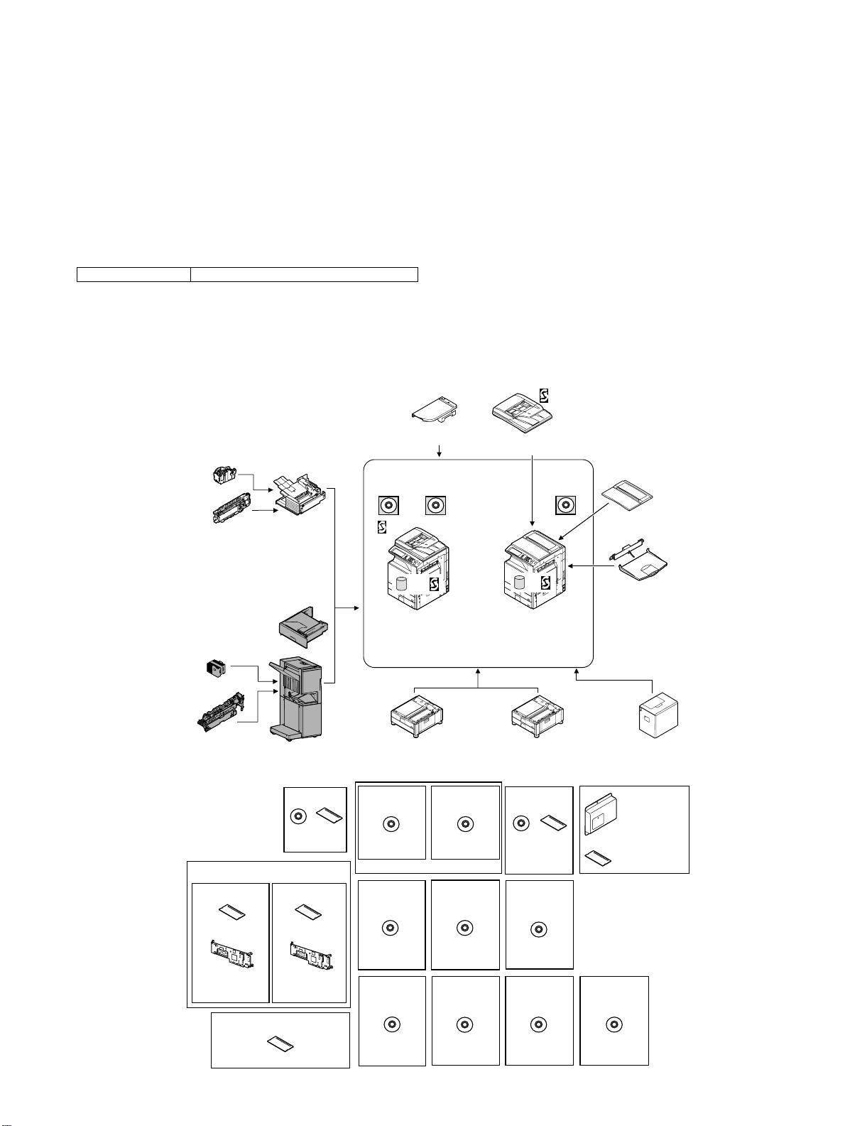
2. Configuration
1) When installing this unit, the paper feed desk (MX-DEX1/DEX2) and the interface unit (MX-RBX1) must be installed together.
2) This unit cannot be installed with the finisher (MX-FNX1) simultaneously.
Staple cartridge
(Approx. 5000 x 3)
(MX-SCX1)
Punch module
●
2-hole (MX-PNX1A)
●
3-hole (MX-PNX1B)
●
4-hole (MX-PNX1C)
●
4-hole (broad space)
(MX-PNX1D)
Staple cartridge
(Approx. 5000 x 3)
(AR-SC2)
Punch module
●
2-hole (AR-PN1A)
●
3-hole (AR-PN1B)
●
4-hole (AR-PN1C)
●
4-hole (broad space)
(AR-PN1D)
(Including document control)
CC authentication
version
Security
ROM
For document
control PWB
(MX-FRX1)
Finisher
(MX-FNX1)
Paper pass unit
(MX-RBX1)
Saddle stitch finisher
(MX-FNX2)
Barcode font kit
CD
ROM
(AR-PF1)
Data security kit
Commercial
version
Security
ROM
For document
control PWB
(MX-FRX1U)
256MB expansion memory board
(MX-SMX1)
(For MX-2300G/2700G)
Device Tray with
USB Hub (MX-RKX1)
PCL5c/PCL6
driver
RSPF
HDD
Copier/Printer (PCL)
/Scanner model
(MX-2300N)
(MX-2700N)
Stand/1x500 sheet
paper drawer
(MX-DEX1)
Printer expansion
kit (PCL)
CD
(MX-PBX1)
(For MX-2300G/2700G)
Internet Fax
expansion kit
CD
(MX-FWX1)
Application
integration
module
CD
(MX-AMX1)
Network
scanner
(Sharpdesk 1 license)
Network scanner
expansion kit
CD
(MX-NSX1)
Sharpdesk
1 license kit
Sharpdesk
5 license kit
CD
(MX-USX1/
USX5)
Sharpdesk
100 license kit
CD
(MX-USA0)
Reversing single pass feeder
(MX-RPX1)
SPLC-c
driver
HDD
Copier/Printer (SPLC-c)
model
(MX-2300G)
(MX-2700G)
Stand/2x500 sheet
paper drawer
(MX-DEX2)
PS3 expansion
kit
CD ROM
(MX-PKX1)
Sharpdesk
10 license kit
Sharpdesk
50 license kit
CD
(MX-US10/
US50)
Application
communication
module
CD
(MX-AMX2)
Document cover
(MX-VRX1)
Exit tray unit
(MX-TRX1)
Large capacity tray
(MX-LCX1)
Facsimile
expansion kit
(MX-FXX1)
FAX memory (8MB)
(packed together)
External
account module
CD
(MX-AMX3)
MX-FNX2/AR-PN1/MX-RBX1 PRODUCT OUTLINE 1 – 1
Page 4

âºíuÇ´
[2] SPECIFICATIONS
Service Manual
1. MX-FNX2
A. Basic specifications
Type Console type finisher
Loading method Ascending offset tray
Transport speed 23/27/35/45 ppm
Transport reference Center reference
Mode types Non-staple, staple
Paper sizes allowed for offset A3, B4, A4, A4R, B5, B5R, 8K, 16K, 11" x 17", 8.5" x 14", 8.5" x 13", 8.5" x 11", 8.5" x 11"R
Offset quantity 20mm, 0.8 inch
Tray type (Number of trays) Upper tray: Lift-up/down offset tray
Paper exit direction Face down
Paper exit paper size A3W, A3, B4, A4, A4R, B5, B5R, A5R, 16K, 16KR
Power consumption 52W
Power source Supplied from the host machine power (DC24V/DC5V)
External dimensions (W x D x H) When the paper exit tray is on the storge position: 555 x 610 x 1010 (mm), 21 27/32 x 24 1/64 x 39 49/64 (inch)
Occupying dimensions (W x D) When the tray is on pull-out position: 665 x 610 (mm), 21 27/32 x 24 1/64 (inch)
Weight Approx. 46kg (101.4 lbs)
Installation/maintenance Installed by service personnel
Optional detection Auto detection supported
Packaged items Parts for mounting, operational sheet, staple directional instruction label, punch directional instrucrtion label,
B. Finishing section
Lower tray: Book tray for saddle stitch
12" x 18", 11" x 17", 8.5" x 14", 8.5" x 13", 8.5" x 11", 8.5" x 11"R, 5.5" x 8.5"R, 7.25" x 10.5"R
When the paper exit tray is on the pull-out position: 665 x 610 x 1050 (mm), 26 11/64 x 24 1/64 x 41 21/64 (inch)
* Distance from the main unit: 300mm, 11 13/16 inch
installation cautionary note
Capacity of paper exit and load Non-staple: 1,000 sheets (Small size) Max. 500 sheets for A5R, INV-R (Plain paper 60 to 80g/m
Staple sort: 30 sets * (Max. 50 sets for small size, one-position stapling at the rear)
Max: 1,000 sheets (Small size)
*: Less than 1,000 sheets and less than 30 sets depending on the use environment and paper curl.
Large size: A3W, A3, B4, 8K, 12" x 18", 11" x 17", 8.5" x 14", 8.5" x 13"
Small size: A4, A4R, B5, B5R, A5R, 16K, 16KR, 8.5" x 11", 8.5" x 11"R, 5.5" x 8.5"R, 7.25" x 10.5"R
Offset function Provided
Paper size which can be stapled A3, B4, A4, A4R, B5, B5R, 8K, 16K, 16KR, 11" x 17", 8.5" x 14", 8.5" x 13", 8.5" x 11", 8.5" x 11"R
Ejectable paper size Determinate
size
Indeterminate
size
Paper weight Thin paper:
Plain paper:
Heavy paper:
Quantity of paper to be stapled (Max.) 30 sheets (Small size, 90g/m
25 sheets (Large size, 90g/m
Stapling 3 kinds (One in the front, one at the back, two positions)
Staple supply Staple cartridge replacement
Staple detection Staple empty detection: Provided (Nearly empty: 40 pcs. remained)
Manual stapling No
or equivalent)
500 sheets (Large size) (Plain paper 60 to 80g/m
500 sheets (Large size)
AB type A3W, A3, B4, A4, A4R, B5, B5R, A5R, 8K, 16K, 16KR
Inch type 12" x 18", 11" x 17", 8.5" x 14", 8.5" x 13", 8.5" x 11", 8.5" x 11"R, 5.5" x 8.5"R,
AB type 148 x 100 to 432 x 297
Inch type 5 1/2" x 5 1/2" to 17" x 11 5/8"
55 to 59g/m
60 to 105g/m
106 to 209g/m
7.25" x 10.5"R
2
(15 to 16 lbs)
2
(16 to 28 lbs)
2
(28 to 56 lbs)
2
(24 lbs))
2
(24 lbs))
2
(16 to 21 lbs) or equivalent)
C. Saddle stitch section
Stapling type Common to the staple specifications. 2-position stapling (center stapling), face down
Folding location Center folding
Paper size A3, B4, A4R, 8K, 16KR, 11" x 17", 8.5" x 11"R
Weight of paper applicable for saddle stitch 55 to 209g/m
Quantity of paper to be stapled 10 sets (6 to 10 sheets), 20 sets (1 to 5 sheets)
2
(15 to 56 lbs)
2
(16 to 21 lbs)
D. Consumable parts
Name Content Life Product name
Staple cartridge Staple cartridge x 3 5000 x 3 AR-SC2
MX-FNX2/AR-PN1/MX-RBX1 SPECIFICATIONS 2 – 1
Page 5
2. AR-PN1A/B/C/D
A
ABA
A
ABA
A
B
C
Type Punch unit for saddle finisher
Punch type 2 holes / 3 holes / 4 holes / 4 holes (wide)
Transport speed 23, 27, 35, 45, sheets/min.
Transport reference Center reference
Punch dust full detection Provided
Paper exit direction Face down
Paper weight Plain paper: 60 to 105g/m
Puchable paper size 2 holes
Power source Supplied from the finisher
External dimensions (W x D x H) 105 x 560 x 175 (mm), 4 9/64 x 22 3/64 x 6 57/64 (inch)
Weight Approx. 2.9kg (6.4 lbs)
Packaged items Parts for mounting, instructional label for garbage pickup
*1: Auto switching: 2 holes/3 holes
Kind of hole punch
A punch unit that provides all of these 4 types can be installed.
2
(16 to 28 lbs)
Thin paper: 55 to 59g/m
Heavy paper: 106 to 209g/m
(AR-PN1A)
3 holes *1
(AR-PN1B)
4 holes
(AR-PN1C)
4 holes (wide)
(AR-PN1D)
A3, B4, A4, A4R, B5, B5R, 11" x 17", 8.5" x 14", 8.5" x 13", 8.5" x 11", 8.5" x 11"R, 8K, 16K, 16KR
3 holes: A3, A4, 11" x 17", 8.5" x 11"
2 holes: 8.5" x 14", 8.5" x 13", 8.5" x 11"R
A3, A4
A3, B4, A4, A4R, B5, B5R, 11" x 17", 8.5" x 14", 8.5" x 13", 8.5" x 11", 8.5" x 11"R
2
(15 to 16 lbs)
2
(28 to 56 lbs)
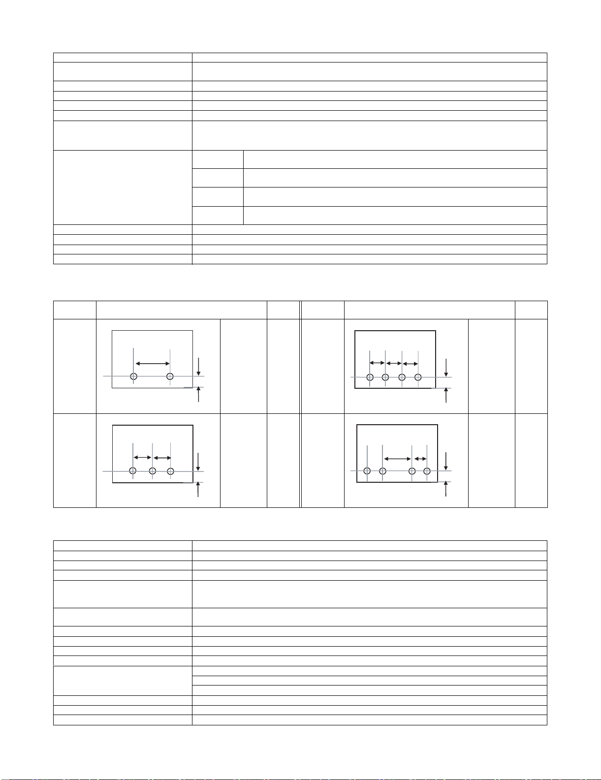
Kind Hole position
2 holes
(AR-PN1A)
A: 80±1mm
B: 12±3mm
Hole
size
φ6.5mm 4 holes
Kind Hole position
(AR-PN1C)
B
3 holes
(AR-PN1B)
A: 108±1mm
B: 12±3mm
φ8.0mm 4 holes
(wide)
(AR-PN1D)
3. MX-RBX1
Type Paper pass unit
Paper reception reference Center referance
Receiving speed 62 to 450mm/sec (23 to 45cpm)
Receiving and sending speed 23 to 45cpm
Paper weight Thin paper:
Plain paper:
Heavy paper:
Transportable paper sizes A3W, A3, B4, A4, A4R, B5, B5R, A5R, 16K, 16KR
12" x 18", 11" x 17", 8.5" x 14", 8.5" x 13", 8.5" x 11", 8.5" x 11"R, 5.5" x 8.5"R, 7.25" x 10.5"R
External dimensions (W x D x H) 555 x 535 x 165 (mm), 21 27/32 x 21 1/16 x 6 1/2 (inch)
Weight Approx. 7kg (15.4 lbs)
Power source Supplied by saddle finisher
Power consumption Included with saddle finisher power consumption
Interface Mechanical: Fixed to the main unit with screws.
Electrical: Cable connection from the finisher
Control: Controlled by the communication command from the main unit through the finisher.
Installation/maintenance Installed by service personnel
Optional detection Auto detection supported
Packaged items Parts for mounting, installation cautionary note
55 to 59g/m
60 to 105g/m
106 to 209g/m
2
(15 to 16 lbs)
2
(16 to 28 lbs)
2
(28 to 56 lbs)
A: 80±1mm
B: 12±3mm
A: 70±1mm
B: 12±3mm
C: 21±1mm
Hole
size
φ6.5mm
φ6.5mm
MX-FNX2/AR-PN1/MX-RBX1 SPECIFICATIONS 2 – 2
Page 6

âºíuÇ´
[4] EXTERNAL VIEWS AND INTERNAL STRUCTURES
Service Manual
1. Part names and functions
A. External view
1
6
3
5
1 Staple compiler 4 Front cover
2 Top cover 5 Saddle stitch tray
3 Staple section 6 Offset tray
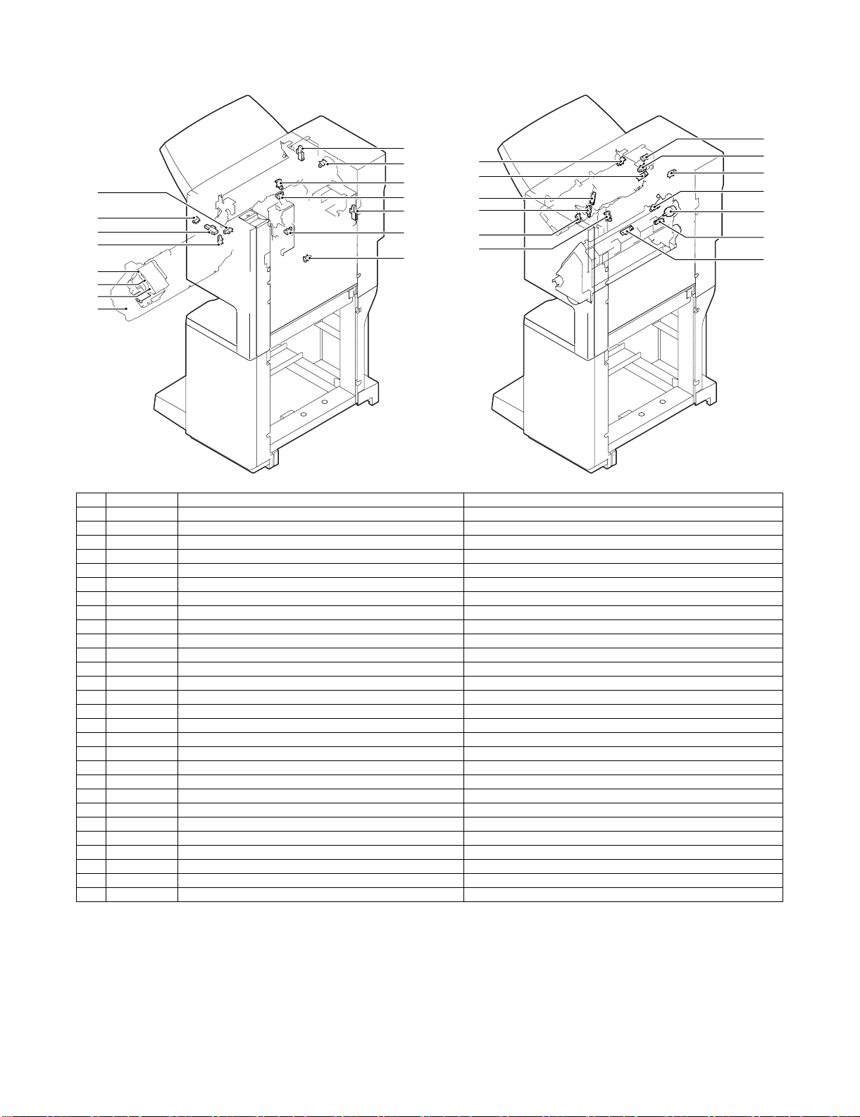
B. Internal structure
(1) Finisher section
1 2 3 754 6
2
4
1614 1513 17128 9 10 11
1 Paper exit tray 10 Stapler
2 Alignment plate (Front, back) 11 Saddle section
3 Paddle 12 Book making stopper
4 Paper exit roller 13 Book making tray
5 Process tray stopper 14 Bundle transport roller
6 Transport roller 15 Book making exit roller
7 Punch section (Option) 16 Paper folding roller
8 Paper exit belt 17 Paper pushing plate
9 Bundle exit roller
MX-FNX2/AR-PN1/MX-RBX1 EXTERNAL VIEWS AND INTERNAL STRUCTURES 4 – 1
Page 7
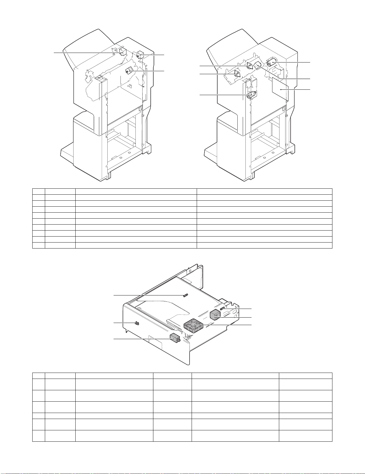
(2) Punch section (Option: AR-PN1A/B/C/D)
31 2 4
1 Die 3 Punch
2 Cam 4 Punch dust box
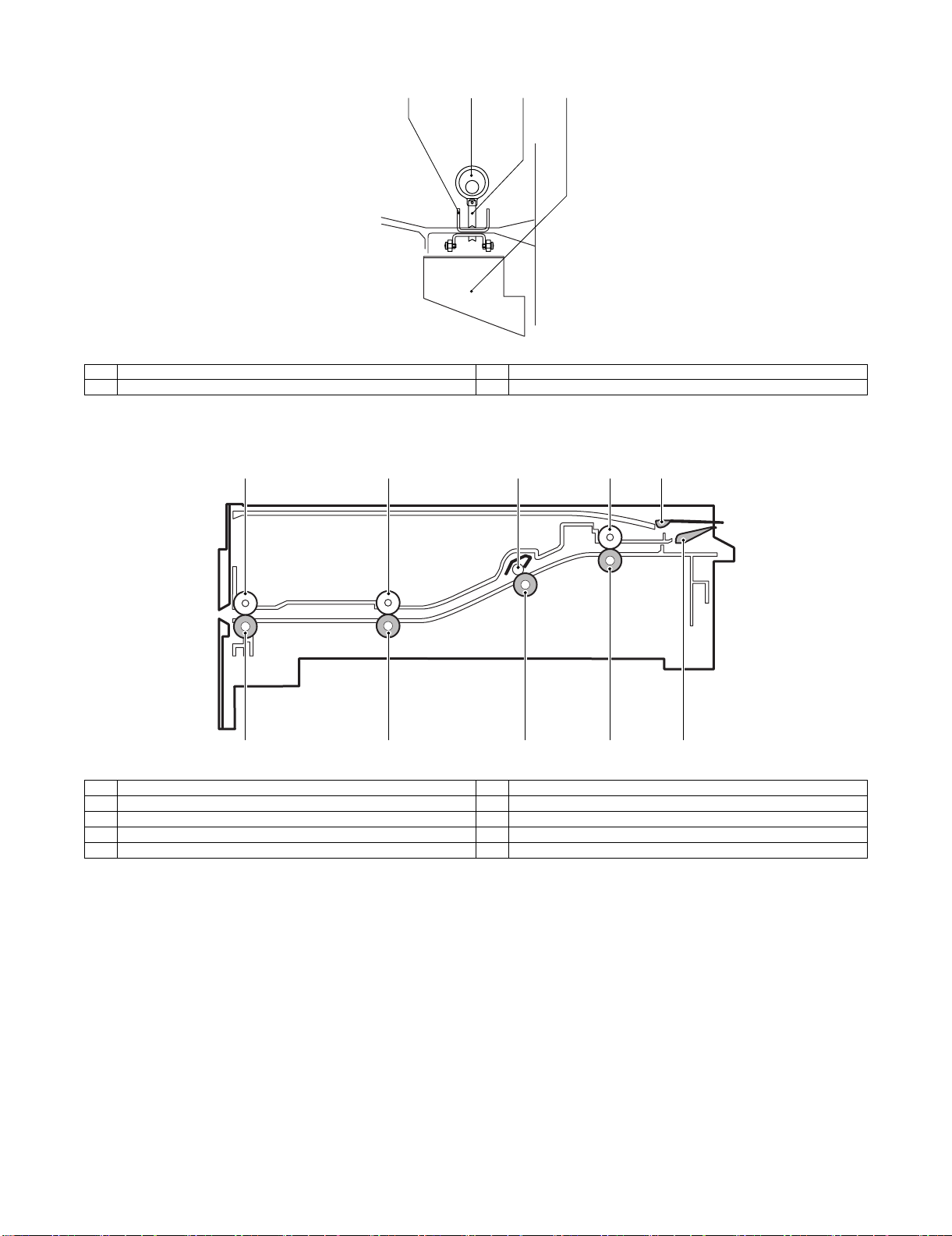
(3) Interface transport section (MX-RBX1)
1
5
1 Paper exit roller 6 Paper exit front roller
2 Paper exit front roller 7 Inlet port rear roller
3 Inlet port rear roller shaft 8 Inlet port roller
4 Inlet port roller 9 Reverse flapper
5 Paper exit roller 10 Upper guide flapper
2
6
3
7
4
8
9
10
MX-FNX2/AR-PN1/MX-RBX1 EXTERNAL VIEWS AND INTERNAL STRUCTURES 4 – 2
Page 8
C. Finisher and saddle section
(1) Sensor, switch and clutch
26
5
2
7
6
8
9
23
24
22
14
28
16
4
25
17
13
19
20
21
18
No. Signal Name Active condition
1 FED Entry paper sensor Paper detected: "H"
2 FPDHPD Paddle home position sensor Paddle HP: "H"
3 FARHPD Bundle roller home position sensor Oscillation guide HP: "H"
4 FFJHPD Alignment home position sensor (front) Alignment tray (F) HP: "H"
5 FRJHPD Alignment home position sensor (rear) Alignment tray (R) HP: "H"
6 FAD Alignment tray sensor Paper detected: "H"
7 FOBHPD Exit belt home position sensor Paper exit belt HP: "H"
8 FBED Tray paper sensor Tray paper detected: "H"
9 FSLD Paper level sensor Paper detected: "H"
10 FFPD Bookbinding position sensor Paper detected: "L"
11 FFHPD Bookbinding home position sensor Folding operation HP: "L"
12 FFRHPD Bookbinding roller home position sensor Bundle transport roller HP: "H"
13 FFED Bookbinding paper sensor Paper detected: "H"
14 FFE Bookbinding lock sensor
15 FULD Lift upper sensor Tray upper limit detected: "H"
16 FLLD Lift lower sensor Tray lower limit detected: "H"
17 FLE Lift lock sensor
18 FSTHPD Staple shift home position sensor Stapler HP: "H"
19 FSHPD Staple drive home position sensor Stapler stapling HP: "L"
20 FSPD Self prime sensor Cartridge staple detected: "L"
21 FSD Staple empty sensor Stapler cartridge detected: "L"
22 FFDD Front door sensor Front cover open: "H"
23 FCD Upper cover sensor Upper cover open: "H"
24 FFDDW Front door switch Front door closed: "H"
25 FJSW Joint switch Printer connected: "H"
26 FSSSW Staple safety switch Oscillation guide closed: "H"
27 FCC Bookbinding clutch When drive is transmitted: "H"
28 FMLD Tray middle sensor Tray middle detected: "H"
15
3
1
12
27
11
10
MX-FNX2/AR-PN1/MX-RBX1 EXTERNAL VIEWS AND INTERNAL STRUCTURES 4 – 3
Page 9
(2) Motor and PCB
2
1
5
8
4
6
No. Signal Name Active condition
1 FFM Transport motor Paper transport
2 FPM Paddle motor Oscillation guide drive, paper exit to offset tray
3 FAM Bundle exit motor Paper exit operation
4 FFJM Alignment motor (front) Alignment plate (F) drive
5 FRJM Alignment motor (rear) Alignment plate (R) drive
6 FLM Lift motor Paper exit tray up/down
7 FFSM Staple motor Stapling/paper folding
8 FSM Staple shift motor Staple unit sliding
9 PBA-CONT Control PCB Finisher control
7
3
9
D. Interface transport section (MX-RBX1)
2
1
3
5
No. Signal Name Type Function/Operation Output
1 FJPID Interface transport unit inlet port sensor Photointerrupter Interface inlet port paper detection LO light is interrupted
2 FJPOD Interface transport unit outlet port
sensor
3 FJPDD Interface transport unit cover sensor Photointerrupter Interface cover open detection Light is interrupted when
4 FJPM Interface transport motor Paper transport roller drive
5 FINRPS Interface reverse path solenoid Drive of the flapper which selects the path in
6 FJFM Interface fan Temperature rise protection fan in the
Photointerrupter Interface outlet port paper detection LO light is interrupted
the finisher and the reverse path
finisher inlet port section
4
6
when paper is provided.
when paper is provided.
the cover is open.
MX-FNX2/AR-PN1/MX-RBX1 EXTERNAL VIEWS AND INTERNAL STRUCTURES 4 – 4
Page 10
E. Punch section (AR-PN1A/B/C/D)
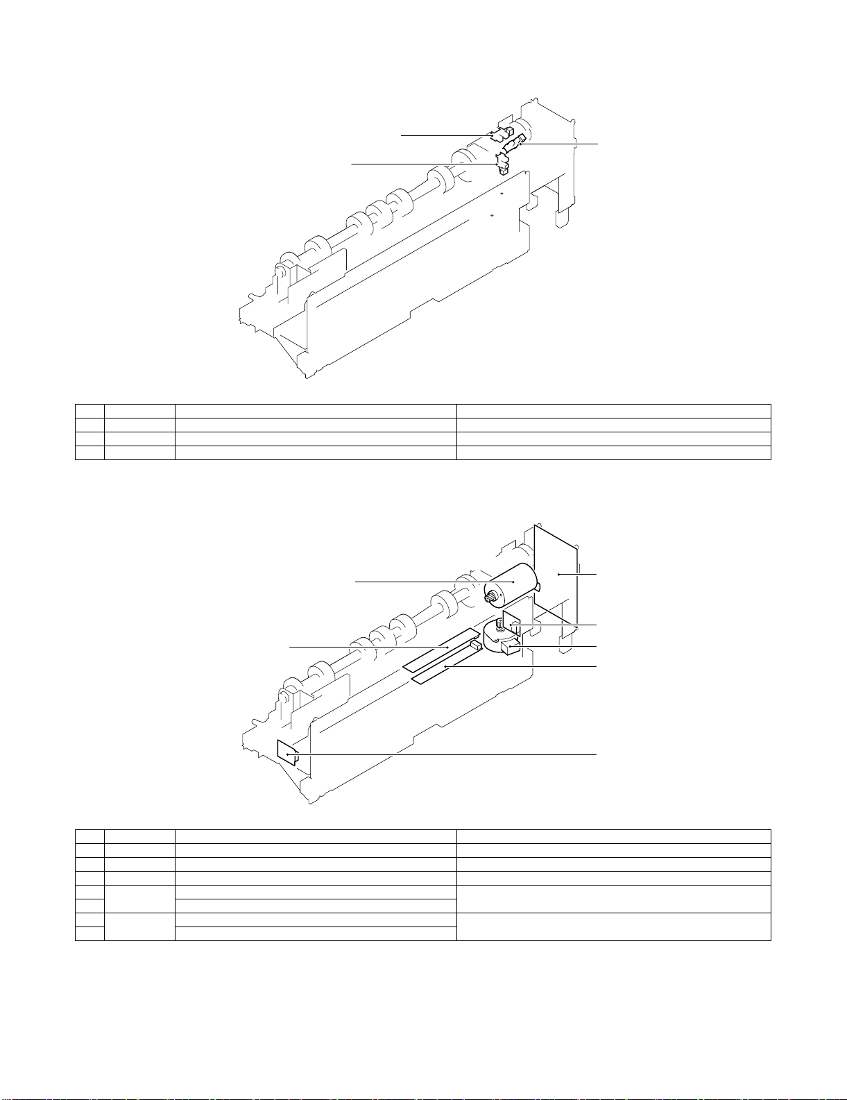
(1) Sensor
3
1
2
No. Signal Name Active condition
1 FPHPD Punch home position sensor Punch HP detected: "L"
2 FPSHPD Punch side resist home position sensor Punch slide unit HP detected: "H"
3 FPMCK Punch motor lock sensor
(2) Motor and PCB
1
3
6
4
2
5
7
No. Signal Name Active condition
1 FPNM Punch motor Punch drive
2 FPSM Punch side resist motor Punch slide unit transverse move
3 Punch control PCB
4FPTD
FPSD1 – 4
5 Side resist LED PCB
6 FPDD Dust full photo sensor PCB Punch dust full detection
7 Dust full LED PCB
Side resist photo sensor PCB Punch horizontal resist and punch timing detection
MX-FNX2/AR-PN1/MX-RBX1 EXTERNAL VIEWS AND INTERNAL STRUCTURES 4 – 5
Page 11
âºíuÇ´
[5] OPERATIONAL DESCRIPTION
1. Basic operations
A. Specifications
The finisher serves to deliver sheets coming from its host machine.
The mode of delivery may be non-sort stack, job offset *, or staple
delivery.
The saddle unit built into the finisher is used to fold a stack of
sheets coming from the finisher unit in half for delivery.
The punch unit (option) is designed for installation to the pickup
assembly of the finisher, and is used to punch holes in sheets coming from the host machine.
The above operations are controlled with various commands from
the finisher controller PCB as well as the commands from the
punch controller PCB.
Punch unit drive
system (punch unit;
option)
Alignment drive system
Stapler drive system
Delivery drive system
Feed drive system
Control system
Tray drive system
Saddle section
drive system
Interface pass
drive system
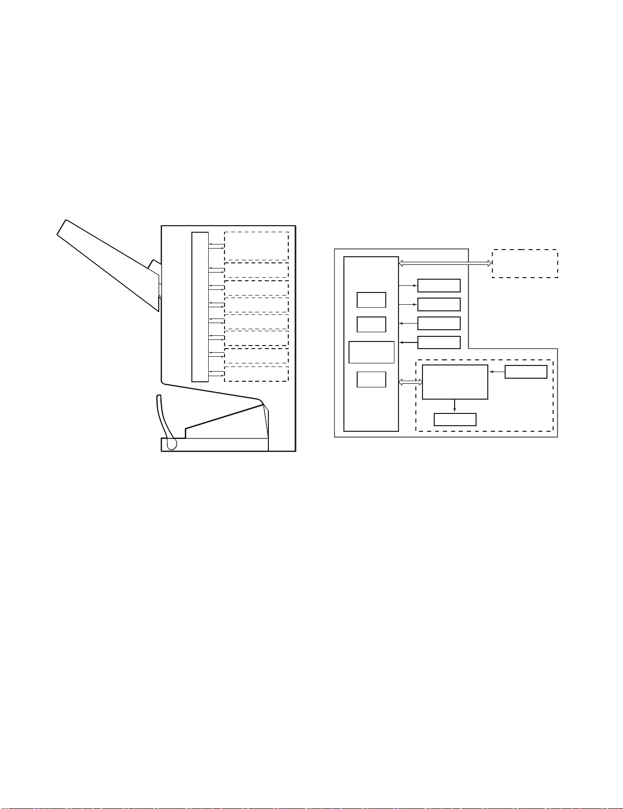
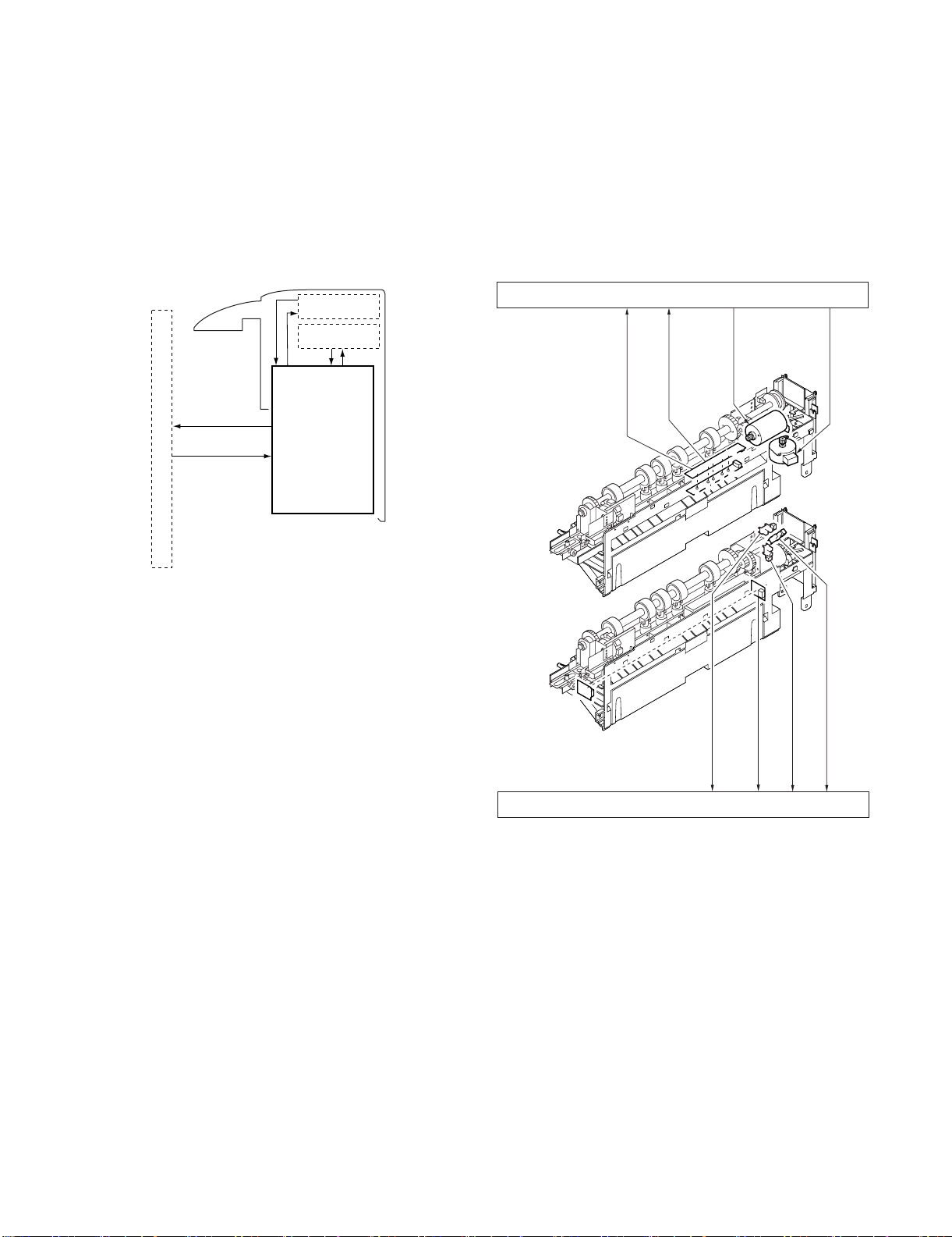
B. Outline of the Electrical Circuitry
Service Manual
The sequence of finisher operations is controlled by the finisher
controller PCB. The finisher controller PCB is a 16-bit microprocessor (CPU), and is also used for combination with the host machine
(serial).
The finisher controller PCB drive motors and other loads in
response to the various commands from the host machine. It also
communicates such data as on the states of various sensors and
switches to the host machine by way of the serial communication
line.
The ICs mounted to the finisher controller PCB have the following
functions:
• IC13 (CPU): Controls sequence of operations.
• IC12 (EEP-ROM): Backs up adjustment settings.
• IC6: Stores sequence programs.
• IC11 (expansion port): I/O port
The flow of signals between finisher and options controller is shown
as below.
Finisher unit
Host machine DC
Finisher
controller
PCB
IC13
CPU
IC12
EEP-ROM
IC11
Communication
IC
IC6
ROM
Motor
Clutch
Switch
Sensor
Punch unit (option)
Punch controller
PCB
controller PCB
CPU
Sensor
*: The position of delivery is shifted to the front/rear for each stack
to assist sorting.
Motor
MX-FNX2/AR-PN1/MX-RBX1 OPERATIONAL DESCRIPTION 5 – 1
Page 12

C. Inputs to and Outputs from the Finisher
When the drive is transmitted,
‘1’.
Switches between ‘1’and
‘0’ according to the
direction of motor rotation.
Switches between ‘1’and
‘0’ according to the
direction of motor rotation.
Switches between ‘1’and
‘0’ according to the
direction of motor rotation.
Switches between ‘1’and
‘0’ according to the
direction of motor rotation.
Switches between ‘1’and
‘0’ according to the
direction of motor rotation.
Finisher controller PCB
Feed motor
FEEDMTR_A
+24V
CN10-1
-1
CN62-5
Paddle motor
+24V
FPM
FFC
B_CLU
+24V
CN72
-1
-2
-2
-1
CN18-1
-2
Binding clutch
Bundle exit motor
+24V
FAM
Alignment motor
(front)
+24V
FFJM
Alignment motor
(rear)
+24V
FRJM
-2
-3
-4
-5
-6
FFM
-2
-3
-4
-5
-6
CN56
-6
-5
-4
-3
-2
-1
FEEDMTR_*A
FEEDMTR_B
FEEDMTR_*B
PDLMTR_A
PDLMTR_*A
PDLMTR_B
PDLMTR_*B
CN10-7
-8
-9
-10
-11
-12
-1
-2
-3
-4
-5
-6
CN57
-6
-5
-4
-3
-2
-1
EJCTMTR_A
EJCTMTR_*A
EJCTMTR_B
EJCTMTR_*B
CN13-1
-1
-2
-3
-4
-5
-6
-2
-3
-4
-5
-6
CN59
-6
-5
-4
-3
-2
-1
CN3-1
-2
-3
-4
-5
FJOGMTR_A
FJOGMTR_*A
FJOGMTR_B
FJOGMTR_*B
CN63-1
-2
-3
-4
-5
-4
-3
-2
-1
CN64-5
CN3-6
-7
-8
-9
-10
CN65-1
-2
-3
-4
-5
-4
-3
-2
-1
RJOGMTR_A
RJOGMTR_*A
RJOGMTR_B
RJOGMTR_*B
Finisher controller PCB
Lift motor
SIFTMTR_1
Switches between ‘+’and
‘–’ according to the
direction of motor rotation.
CN6-1
-2
FLM
-2
-1
CN70
-2
-1
SIFTMTR_0
-2
-1
-2
-1
-2
-1
CN70
-2
-1
Staple motor
BINDMTR_1
Switches between ‘+’and
‘–’ according to the
direction of motor rotation.
CN6-3
-4
FFSM
BINDMTR_0
CN71
Controller PCB
• Inputs to the Finisher Controller PCB (1/2)
Entry paper
sensor
Paddle home
position sensor
Bundle roller
home position
sensor
Aligning plate
home position
sensor (front)
Aligning plate
home position
sensor (rear)
Alignment
tray sensor
Delivery belt
home position
sensor
Tray paper sensor
Paper surface
sensor
Bookbinding
position sensor
FED
FPDHPD
FAR HPD
FFJHPD
FRJHPD
FAD
FOBHPD
FBED
FSLD
FFPD
CN44-3
CN51-1
CN55-3
CN23-3
CN36-3
CN30-3
CN31-3
CN32-3
CN35-3
CN39-3
CN43-1
CN42-3
-3
-1
-2
-2
-3
-2
CN54-1
-3
-1
-2
-2
-1
-2
-1
-2
CN29-1
-3
-1
-2
-2
-4
-6
-1
-2
-5
-7
-9
-1
-8
-2
CN34-1
-3
-1
-2
-2
CN38-1
-2
-2
-3
-1
CN53-3
CN28-9
CN33-3
CN37-9
-1
-2
-1
-2
-7
-8
-6
-4
-5
-3
-1
-2
-1
-2
-8
-7
CN16-10
CN9-1
CN9-7
CN4
CN5-13
CN5-1
CN5-10
CN16-1
-12
-11
-3
-2
-9
-8
-3
-2
-15
-14
-3
-2
-4
-6
-5
-7
-9
-8
-12
-11
-2
-3
Finisher controller PCB
+5V
ENT_S
+5V
PDL_HP
+5V
BDL_ROL_HP
+5V
FJOG_HP
+5V
RJOG_HP
+5V
ADJ_TRAY_S
+5V
EJCT_BLT_HP
+5V
TRY_EMPS
+5V
LVL_S
+5V
BIND_P
BIND_L
When the sensor
detects paper, ‘1’ .
When the paddle is at
home position, ‘1’.
When the swing guide
is at home position, ‘1’.
When the aligning
plate (front) is at
home position, ‘1’.
When the aligning
plate (rear) is at
home position, ‘1’.
When the sensor
detects paper, ‘1’.
When the delivery belt
is at home position, ‘1’.
When paper is present
on the tray,‘1’.
When the paper
surface is detected,
‘1’.
When paper is
detected, ‘0’.
When LED is lit, ‘1’.
• Outputs from the Finisher Controller PCB (1/2)
• Inputs to the Finisher Controller PCB (2/2)
FFHPD
Bookbinding
home position
sensor
Bookbinding
roller home
position sensor
Bookbinding
paper sensor
Bookbinding
lock sensor
Lift upper sensor
Lift lower sensor
Lift lock sensor
Front door sensor
Upper cover sensor
Tray middle sensor
Joint switch
Front door switch
Stapler safety
switch
FFRHPD
FFED
FFE
FULD
FLLD
FLE
FFDD
FCD
FMLD
FJSW
N. O.
FFDDW
N. O.
FSSSW
N. O.
CN40-3
CN41-3
CN47-3
CN52-1
CN50-3
CN49-3
CN48-3
CN25-3
CN24-3
CN73-3
-1
-2
-1
-2
-1
-2
-2
-3
-1
-2
-1
-2
-1
-2
-1
-2
-1
-2
-1
-2
CN69-2
CN68-2
CN66-2
-1
-1
-1
CN38-4
-6
-5
-7
-9
-8
CN16-4
CN37-6
-4
-5
-3
-1
-2
CN15-1
CN15-10
CN15-7
CN15-4
CN19-1
• Outputs from the Finisher Controller PCB (2/2)
Finisher controller PCB
+5V
CN9-6
CN4-7
CN4-4
CN8-6
CN8-4
CN8-2
-6
BIND_HP
-5
-7
+5V
-9
BIND_ROL_HP
-8
+5V
-3
BIND_EMPS
-2
+5V
-5
BIND_CLK
-4
+5V
-12
SIFT_UPLMT
-11
+5V
-9
SIFT_DNLMT
-8
+5V
-6
SIFT_CLK
-5
+5V
-9
FDOOR_S
-8
+5V
-6
TOPCOV_S
-5
+5V
-3
PAPE R_ F
-2
+24VP
-5
-3
-1
JOINT SW
FRONT SW
STPLSAFE SW
When at folding home
position, ‘0’.
When the stack feed roller
(upper) is at home position, ‘1’.
When the sensor
detects paper, ‘1’.
When the staple/fold motor is
rotating, alternates between
‘1’ and ‘0’.
When the tray is at the
upper limit, ‘1’.
When the tray is at the
lower limit, ‘1’.
While the lift motor
is rotating, alternates
between ‘1’ and ‘0’.
When the front door
is open, ‘1’.
When the upper cover
is open, ‘1’.
When the paper is
full, ‘1’.
When connected to
the host machine, ‘1’.
When the front
door is closed, ‘1’.
When the swing
guide is closed, ‘1’.
MX-FNX2/AR-PN1/MX-RBX1 OPERATIONAL DESCRIPTION 5 – 2
Page 13
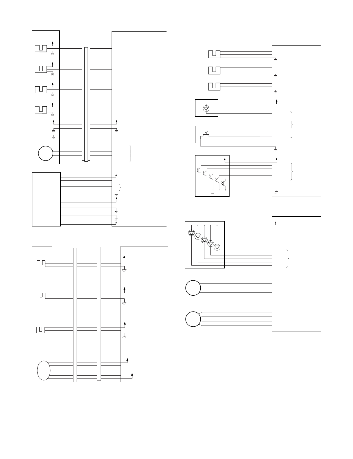
• Inputs to and Outputs from the Finisher Controller PCB (1/2)
Punch controller PCB
-1
J2008-3
+5V
PUNCH
-2
-6
J1006-4
-5
SREG1*
SREG2*
SREG3*
-9
-10
-11
J1007-12
-13
SREG4*
-8
PAEND*
-7
Horizontal
registration
home position
sensor
FPMCK
-1
J2009-3
+5V
CLOCK
-2
-9
J1006-7
-8
Punch home
position sensor
+5V
+5V
PT1
PT2
PT3
PT4
PT5
FPSHPD
FPHPD
-1
J2007-3
+5V
SLIDE
-2
-3
J1006-1
-2
Punch motor
lock sensor
Side resist photo sensor PCB (FPTD)
DUSTLED
Waste full LED PCB
J1005-1
PT131
LED121
DUSTPTR
+5V
4
Waste full photosensor PCB (FPDD)
-2
J1005-3
When the hole puncher is
at home position, ‘0’.
While the punch motor
is rotating, alternates
between ‘0’and ‘1’.
When the punch slide
unit is at home position,
‘1’.
When paper is
detected, ‘0’.
When the light is
blocked, ‘0’.
Stapler unit
Staple shift home
position sensor
FSTHPD
Staple driver home
position sensor
FSHPD
Staple empty
sensor
FSD
Self prime
sensor
FSPD
Staple shift motor
FSM
Host
machine
+5V
+5V
+5V
+5V
+5V
CN72-5
CN72-4
CN72-3
CN72-2
CN72-6
CN72-1
CN72-7
CN72-10
CN72-11
CN72-12
CN72-13
CN72A-5
CN72A-4
CN72A-3
CN72A-2
CN72A-6
CN72A-1
CN72A-7
CN72B-5
CN72B-4
CN72B-3
CN72B-2
CN72A-5
CN72A-4
CN72A-3
CN72A-2
CN72A-6
CN72A-1
CN72A-7
CN72B-5
CN72B-4
CN72B-3
CN72B-2
CN11-3
CN11-4
CN11-5
CN11-6
CN11-2
CN11-7
CN11-1
CN7-3
CN7-4
CN7-5
CN7-6
CN2-1
CN1-5
CN1-3
CN1-2
CN1-1
SLID_HP
STPL_HP
HOOK_S
SELF_P
STPL_CNCT
SLIDMTR_A
SLIDMTR_*A
SLIDMTR_B
SLIDMTR_*B
-3
GND
-4
GND
-5
TXD
-7
RXD
-6
+5V
+24V
+24V
+5V
Finisher controller PCB
When the stapler is at home
position, ‘1’.
When the stapler is at
stapling home position, ‘0’.
When the cartridge has
staples, ‘0’.
When the staple is at top
the stapler, ‘0’.
When the stapler is
connected, ‘0’.
Switches between ‘1’and
‘0’ according to the direction
of motor rotation.
Communication line
• Inputs to and Outputs from the Finisher Controller PCB (2/2)
-2
-3
Finisher control PWB
+5V
"0" when paper is detected.
LVL_E_S
Interface transport
unit inlet port
sensor
FJPID
CNFJ2-1
-3
-2
CNFJ1-
-17
-16
CNFJ1-
-17
-16
CN73C-1
-2
-3
CN73A-8
-7
-6
CN21-
D. Inputs to and Outputs from the Punch
Controller PCB (option)
• Inputs to and Outputs from the Punch Controller PCB
• Outputs from the Punch Controller PCB
LEDON5
LEDON4
LEDON3
LEDON2
LEDON1
Punch controller PCB
When ‘1’, LED goes ON.
Side resist LED PCB (FPSD)
LED5
LED4
LED3
LED2
LED1
J1007-6
+5V
-1
-5
-4
-3
-2
Interface transport
unit outlet port
sensor
FJPOD
Interface transport
unit cover sensor
FJPDD
Interface
transport
motor
FJPM
Punch motor
J1002-1
CNFJ3-1
-3
-2
CNFJ4-3
-2
-1
CNFJ5
-4
-3
-1
-2
-5
CNFJ1-
-14
-13
CNFJ1-
-11
-10
CNFJ1-2
-7
-6
-5
-4
-3
CNFJ1-
-14
-13
CNFJ1-
-11
-10
CNFJ1-2
-7
-6
-5
-4
-3
CN73C-4
CN73C-7
CN73D-2
CN73D-9
CN73A-5
-5
-4
-6
-3
CN73A-2
-1
-8
CN73B-8
CN73B-
-6
-4
-5
-5
-6
-4
-3
-7
-2
-8
MX-FNX2/AR-PN1/MX-RBX1 OPERATIONAL DESCRIPTION 5 – 3
CN21-4
-5
LVL_P_S
-6
CN21-7
-8
LVL_C_S
-9
CN19-
-2
A
-3
*A
-4
B
-5
*B
-6
+5V
"0" when paper is detected.
+5V
"0" when the interface
transport cover is open.
+24V
The pulse signal is
switched depending
on the motor RPM.
+24V
FPNM
Punch side resist motor
FPSM
J1001-1
-2
-2
-3
-4
A
B
A*
B*
Switches between ‘+’
and ‘–’ according to
the direction of motor
rotation.
Switches the pulse
signals according to
the rotation of the motor.
Page 14
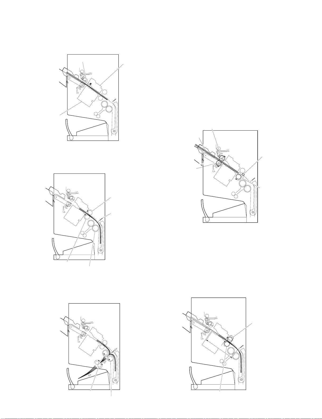
2. Feed/Drive System
(
y)
A. Outline
The machine performs the following in response to the commands
coming from its host machine on the sheets arriving from the host
machine for delivery: simple stacking, job offset, and stapling or
folding (in two).
If a punch unit (option) is installed, the sheets are pouched and
delivered to the delivery tray.
Sheets may be delivered in either of five ways (including one for
the punch unit):
Normal deliveryDelivery method
(1) Normal Delivery
a. Simple Stacking
The machine pulls in the sheet once to the processing tray and
then delivers it to the delivery tray.
Simple stacking
Job offset
Stapling Front 1-point stapling
Rear 1-point stapling
Middle 2-point stapling
Punching
StitchingSaddle delivery
Middle 2-point stapling
b. Job Offset
The machine pulls the sheet once to the processing tray. It then
moves the sheet to the front or the rear using the aligning plate.
When it has deposited a specific number of sheets, it delivers them
in the form of a aligning plane. When the number of sheets stacked
on the processing tray reaches a specified value, the sheets are
delivered in a form of a stack.
Tray
Paper
Results of offset delivery (4 jobs)
4th set
3rd set
1st set
direction of deliver
2nd set
c. Stapling
The machine stacks sheets coming from its host machine on the
processing tray. When the number of sheets stacked on the processing tray reaches a specified value, the finisher staples them
delivers the stapled stack to the delivery tray.
MX-FNX2/AR-PN1/MX-RBX1 OPERATIONAL DESCRIPTION 5 – 4
Page 15
d. Saddle Delivery
Staple motor
drive signal BINDMTR
Bookbinding lock sensor
detect signal BIND_CLK
Finisher controller PCB (1/2)
Lift motor drive signal SIFTMTR
Bundle exit motor drive signal EJCTMTR
Staple slide motor drive signal
SLIDMTR
Paddle motor
drive signal PDLMTR
Alignment motor (rear)
drive signal RJOGMTR
Bind clutch
drive signal B_CLU
Interface transport motor
drive signal RIM
Alignment motor (front)
drive signal FJOGMTR
FFE
FRJM
FPM
FFSM
FFC
FAM
FSM
FLM
FFJM
FJPM
FFM
Finisher controller PCB (2/2)
Feed motor
drive signal FEEDMTR
Finisher controller PCB
FFPD
Bookbinding position
detect signal BIND_P
FED
Entry paper detect signal
ENT_S
The machine deposits a stack of sheets on the processing tray, staples it (middle 2-point), and then moves it to the saddle unit. The
saddle unit folds the stack in two, and delivers it to the bind tray.
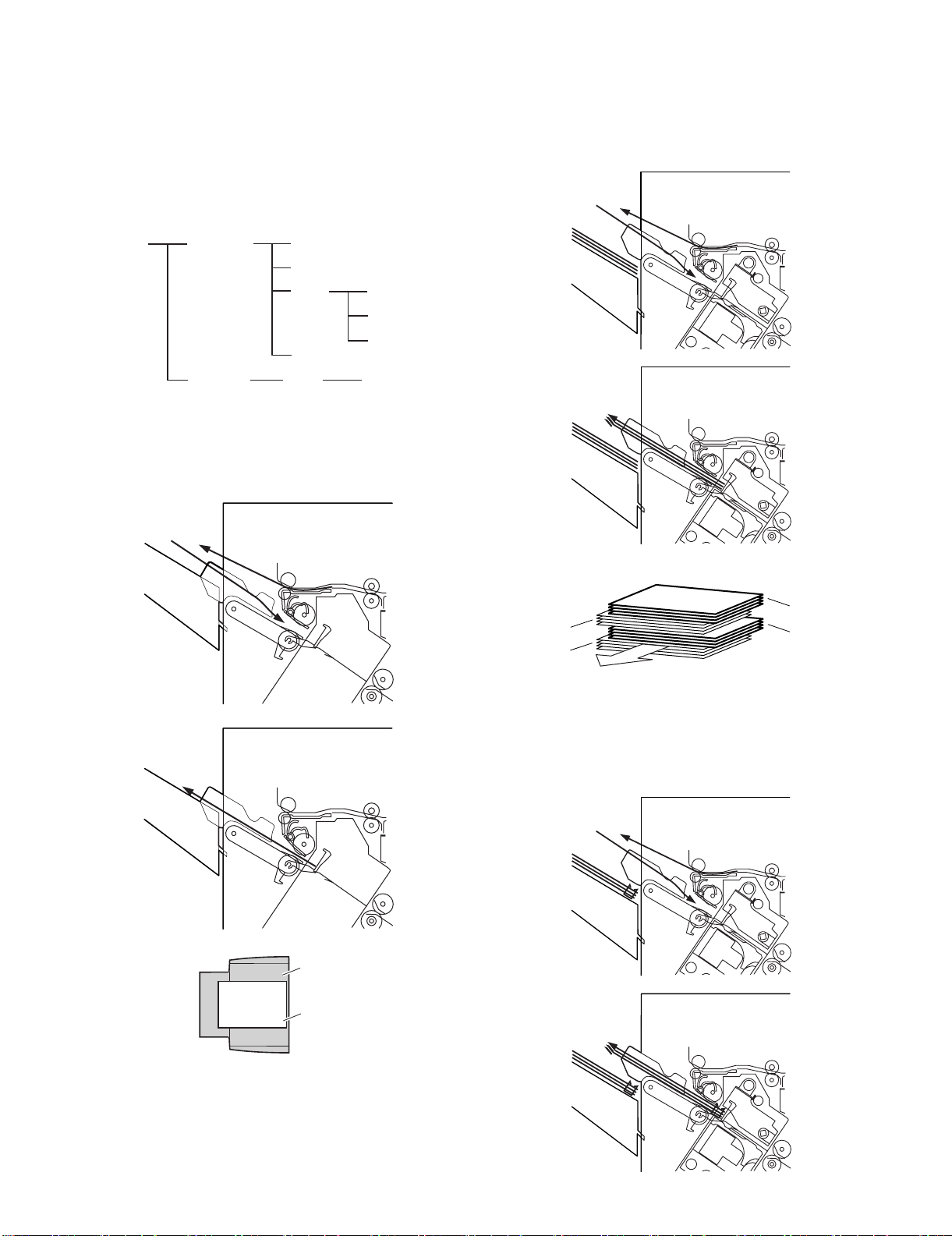
B. Feed/Delivery
(1) Outline
The machine forwards the sheets coming from its host machine to
the delivery tray, processing tray, or saddle unit according to the
type of delivery used. The sheets forwarded to the processing tray
or the saddle unit are offset, stapled, or folded.
The following table shows the motors that are associated with moving and aligning sheets. These motors are controlled (rotated clockwise or counterclockwise) by the microprocessor (CPU) on the
finisher controller PCB.
The paper path is equipped with the sensors shown in the following
figure used to monitor the arrival or passage of sheets.
If a sheet fails to arrive at or move past a specific sensor within a
specific period of time, the finisher controller will assume a jam, and
stops the ongoing operation and, at the same time, communicates
the presence of a jam to the host machine.
Notation Name Description
FFM Feed motor Stepping motor CN10
FPM Paddle motor Stepping motor CN10
FAM Bundle exit motor Stepping motor CN13
FFJM Alignment plate motor
(front)
FRJM Alignment plate motor
(rear)
Stepping motor CN3
Stepping motor CN3
FFSM Staple motor Brush DC motor CN6
FJPM Interface transport motor Stepping motor CN21
Connector on
finisher
controller PCB
Notation Name Description
Connector on
controller PCB
FED Entry paper sensor Photointerrupter CN16
FFPD Bookbinding position
Photointerrupter CN16
sensor
finisher
MX-FNX2/AR-PN1/MX-RBX1 OPERATIONAL DESCRIPTION 5 – 5
Page 16

C. Job Offset
(1) Outline
"Job offset" refers to the operation by which the machine delivers a
set of sheets with them pulled forward or backward for sorting.
Switching between the forward and backward directions is made
using an aligning plate (front) and an aligning plate (rear).
The sheet coming between the delivery rollers is fed onto the processing tray and then fed toward the stopper by the paddle.
A swing guide is at the up position while a sheet is being pulled
onto the processing tray or during alignment. It is at the down position during stack feeding, stack delivery, or stapling.
At power-on, the finisher controller PCB drives the aligning motor
(front) (FFJM) and the aligning motor (rear) (FRJM) to return the
two aligning plates to their home positions.
Sensor Symbol Connector
Aligning home position sensor (front) FFJHPD CN4-3
Aligning home position sensor (rear) FRJHPD CN5-15
Stack roller home position sensor FARHPD CN9-9
Paddle home position sensor FPDHPD CN9-3
(3) Offset Operation
Each sheet is pulled forward or backward using the aligning plate
(front) and the aligning plate (rear).
The offset operation is performed each time a sheet is pulled onto
the processing tray.
Offsetting in the forward direction
Aligning plate (rear)
Sheet to be offset
Tr ay
Aligning plate (front)
Function Motor Symbol
Drives the aligning plate (front) Aligning motor (front) FFJM
Drives the aligning plate (rear) Aligning motor (rear) FRJM
Drives the swing guide drive Paddle motor FPM
Drives the paddle (feeds paper) Paddle motor FPM
Aligning home position sensor (rear)
(FRJHPD)
Light-shielding plate
Paper
Alignment motor (front)
(FFJM)
Aligning plate
(front)
(Front)
Light-shielding plate
Aligning home position sensor (front)
(FFJHPD)
Aligning plate
(rear)
Alignment
motor (rear) (FRJM)
(2) Processing Tray Paper Stacking Operation
A sheet coming between the delivery rollers is fed onto the processing tray. Then, the paddle taps on the sheet surface to locate
the sheet against the processing tray stopper.
Paper
Aligning plate
Paddle
Stack delivery roller (upper)
Offsetting in the backward direction
Aligning plate (rear)
Sheet to be offset
Tray
Aligning plate (front)
(4) Stack Delivery Operation
Stack delivery takes place when 1 sheet of large-size paper or 25
sheets of small-size paper have been stacked on the processing
tray with them offset in either direction.
The paddle motor (FPM) rotates and the swing guide descends to
hold the paper stack between the upper and lower stack delivery
rollers. The stack delivery motor (FAM) rotates in the forward direction to rotate the delivery rollers, feeding the paper stack in the
delivery direction. The delivery belt home position sensor is turned
OFF. The delivery motor is driven a specified number of pulses,
causing the swing guide to ascend. Next, the paper delivery motor
is driven. Next, the delivery motor is driven to deliver the paper
stack with the nails of the delivery belt that rotates in sync with the
stack delivery rollers.
Delivery belt
Swing guide
Swing guide
Processing tray stopper
Stack delivery roller (lower)
MX-FNX2/AR-PN1/MX-RBX1 OPERATIONAL DESCRIPTION 5 – 6
Page 17

Job offset sequence
Start signal
Entry paper sensor
(FFD)
Alignment tray sensor
(FAD)
Feed motor (FEM)
Bundle exit motor(FAM)
Delivery belt home
position sensor (FOBHPD)
Paddle motor (FPM)
Paddle home position
sensor (FPDHPD)
Bundle roller homeposition
sensor (FARHPD)
Staple safety switch
(FSSSW)
Alignment motor (front)
(FFJM)
Alignment home position
sensor (front) (FFJHPD)
Alignment motor (rear)
(FRJM)
Alignment home position
sensor (rear) (FRJHPD)
Host machine delivery signal
∗
4 ms (A4)
∗
Variable by the size
60msec
4ms(A4)
∗
30msec
∗∗
4ms(A4)
220msec
: CW rotation : CCW rotation
4ms(A4)
3. Stapling Operation
A. Outline
Staple operation is performed to staple a specified sheets of paper
using a stapler unit.
The stapling position depends on the staple mode and paper size.
When the machine starts immediately after power-on, the finisher
controller PCB drives the staple shift motor (FSM) to return the stapler unit to the home position. The stapler unit starts moving toward
the front of the stapler frame. It stops when the staple shift home
position sensor (FSTHPD) on the slide PCB located under the stapler unit. Next, the staple shift motor (FSM) is driven a specified
number of pulses. The stapler unit moves to rear standby position
at the back of the machine, entering the standby state.
B. Stapling Operation
When stacking and alignment of paper on the processing tray are
complete, the finisher controller PCB drives the paddle motor
(FPM) in the reverse direction and lowers the swing guide. When
the swing guide descends, the paper stack is sandwiched between
the upper and lower stack delivery rollers.
The finisher control PCB shifts the stapler according to the specified staple position to perform stapling. (Only for B5-R, 1-position
bottom stapling is made at the rear side of 2-posiiton stapling.)
When the stapler shifts toward you, the process tray stopper is put
down to the lower side.
Paper stack
Swing guide
Stack delivery roller (upper)
Processing tray
stopper
Delivery tray
Paddle motor (FPM)
Stack
delivery
roller
(lower)
Stapler
Bundle roller home
position sensor
(FARHPD)
Light-shielding plate
Sensor Symbol Connector Function Remarks
Staple shift
home position
sensor
FSTHPD CN11-3 Detects the home
position for the
stapler moving
back and forth.
Staple drive
home position
sensor
Self prime
sensor
FSHPD CN11-4 Detects the home
position for the
stapling operation
FSPD CN11-5 Detects presence
or absence of
In the
stapler
In the
stapler
staples in the
cartridge.
Staple empty
sensor
FSD CN11-6 Cartridge empty
detection
In the
stapler
Function Motor Symbol Remarks
Moves the stapler. Staple shift motor FSM —
Performs stapling operation Staple motor FFSM —
Stapler
(Deliver direction)
Light-shielding plate
Staple
shift motor
(FSM)
Paper stack
—
Staple safety
switch (FSSSW)
Swing guide
Stack delivery
roller (upper)
Stack delivery
roller (lower)
Staple shift home position sensor (FSTHPD)
MX-FNX2/AR-PN1/MX-RBX1 OPERATIONAL DESCRIPTION 5 – 7
Page 18

C. Delivery Operation after Stapling
When stapling is complete, the finisher controller PCB drives the
stack delivery motor (FAM) in the forward direction to feed the
paper stack (sandwiched between the stack delivery rollers) in the
delivery direction. The delivery belt home position sensor (FOBHPD) is turned OFF. The stack delivery motor (FAM) is driven a
specified number of pulses, causing the swing guide to ascend. At
the same time, the staple shift motor (FSM) is driven to return the
stapler back to the standby position, followed by driving of the stack
delivery motor (FAM). Then, the paper stack is delivered with the
nails of the delivery belt that rotates in sync with the stack delivery
rollers.
Paper stack
Swing guide
Delivery tray
Paddle motor (FPM)
Delivery belt
Stack delivery
roller (lower)
Stack roller home position
sensor (FARHPD)
Light-shielding plate
Stapler
D. Stapler Unit
The staple motor (FFSM) is used to perform stapling operation.
This motor rotates the cam one turn for stapling. The home position
of this cam is detected by the staple drive home position sensor
(FSHPD).
The staple motor (FFSM) is rotated in the forward or reverse direction under the control of the macro computer (IC13) on the finisher
controller PCB.
When the staple drive home position sensor (FSHPD) is OFF, the
finisher controller PCB rotates the staple motor (FFSM) in the forward direction until the sensor turns ON, allowing the staple cam to
the original position.
The staple empty sensor (FSD) is used to detect presence/
absence of a staple cartridge in the machine. The self prime sensor
(FSPD) is used to detect presence/absence of staples in the cartridge.
The finisher controller circuit does not drive the staple motor
(FFSM) unless the staple safety switch (FSSSW) is ON (the swing
guide is close). This assures safety in case where you happen to
put your finger in the stapler.
Staple safety
switch (FSSSW)
Swing guide
Stack delivery
roller (lower)
Stack delivery roller
(upper)
Staple drive home position detect signal
Staple empty detect signal
Cartridge detect signal
Finisher controller PCB
FFSM
Staple motor drive signal
MX-FNX2/AR-PN1/MX-RBX1 OPERATIONAL DESCRIPTION 5 – 8
Page 19
(1) Stapler Movement Controller
The stapler unit is moved by the staple shift motor (FSM). Its home
position is detected by the staple shift home position sensor
(FSTHPD). The stapler waits at the back irrespective of the staple
mode and paper size. After paper has been stacked on the processing tray, the stapler is moved to the specified stapling position
in response to the stapling command from the host machine.
The figure below shows the standby position of the stapler and the
stapling position depending on the staple mode.
1) Front 1-point stapling
The stapler waits at the back. The stapler moves to and
returns from the stapling position for each stapling operation.
4) Middle 2-point stapling (bind mode)
The stapler waits at the back. The stapler moves to and
returns from the stapling position for each stapling operation.
The stapler first staples a paper stack at the rear stapling position and then staples it at the front stapling position.
Standby position
Stapler
Stapling position
Standby position
Stapler
Feed direction
Stopper
Stapling position
2) Rear 1-point stapling
The stapler waits at the back. The stapling position is the same
as the standby position. (Except B5R)
Standby position
Stapling position
Stapler
Feed direction
Stopper
Feed direction
Stapling Operation Sequence
Rear 1-point Stapling of 2 Sheets
Start signal
Entry paper sensor (FED)
Alignment tray sensor
(FAD)
Feed motor (FFM)
Bundle exit motor (FAM)
Exit belt home position
sensor (FOBHPD)
Paddle motor (FPM)
Paddle home position
sensor (FPDHPD)
Bundle roller home
position sensor (FARHPD)
Staple safety switch
(FSSSW)
Alignment motor (front)
(FFJM)
Alignment home position
sensor (front) (FFJHPD)
Staple motor (FFSM)
Staple drive home position
sensor (FSHPD)
Host machine delivery signal
4ms (A4)
Stopper
Stapling position
Stack delivery
Staple
10msec
∗
:CWrotation∗ Variable by the size : CCW rotation
4ms (A4)
∗
20msec
3) Middle 2-point stapling
The stapler waits at the back. The stapler moves to and
returns from the stapling position for each stapling operation.
The stapler first staples a paper stack at the rear stapling position and then staples it at the front stapling position.
Standby position
Stapler
Stapling position
Stopper
Feed direction
Stapling position
MX-FNX2/AR-PN1/MX-RBX1 OPERATIONAL DESCRIPTION 5 – 9
Page 20

4. Delivery Tray Operation
5. Saddle Unit
A. Outline
The machine has a delivery tray in the finisher unit and a bind tray
in the saddle unit.
The bind tray in the saddle unit is of the fixed type and all the folded
paper stacks are delivered to this tray. This tray has a bind tray
sensor (FFED) to detect presence/absence of paper.
The delivery tray in the finisher unit is moved up and down using a
lift motor (FLM).
The finisher has a tray paper sensor (FBED) to detect presence/
absence of paper on the stack tray.
The home position sensor of the delivery tray is detected by the
paper surface sensor (FSLD). When paper has already been
stacked on the delivery tray, the home position is on the top surface
of the stacked paper. When paper has not yet been stacked on the
delivery tray, the home position is at the position where the edge of
the delivery tray is detected. At power-on, the finisher controller
PCB drives the lift motor (FLM) to return the delivery tray to the
home position.
When the paper coming from the processing tray is stacked on the
delivery tray, the lift motor (FLM) is driven a specified number of
pulses, causing the delivery tray to descend. Clock pulses are
detected by the lift lock sensor (FLE). Then, the delivery tray
returns to the home position for the next stacking operation.
The upper limit of the delivery tray is detected by the lift upper limit
sensor (FULD). When the lift upper limit sensor (FULD) is turned
ON, the finisher controller PCB stops the lift motor (FLM) that is
ascending.
The lower limit of the delivery tray is detected by the lift lower limit
sensor (FLLD). When the lift lower limit sensor (FLLD) is turned
ON, the finisher controller PCB stops the lift motor (FLM) that is
descending.
The finisher unit has a tray middle sensor (FMLD) to detect overstacking of large-size or mixed paper according to the stack height.
A. Basic Operations
(1) Outline
The machine stitches a stack of sheets (middle 2-point), then folds
the stack in two in the finisher. These operations are controlled by
the finisher controller PCB.
The finisher controller PCB is controlled by the commands from the
host machine.
B. Feed/Drive System
(1) Outline
This machine stitches the paper stack coming from the finisher,
folds it, and delivers it to the bind tray in the saddle unit in response
to the commands from the host machine.
That is, the machine performs the following operations:
a. Paper feed-in
b. Stitching
c. Stack feed
d. Folding/delivery
a) Paper feed-in
d) Folding/delivery
b) Stitching
c) Stack feed
Lift upper sensor
(FULD)
Lift lower sensor
(FLLD)
Lift lock sensor
(FLE)
Tray middle sensor
(FMLD)
Lift motor (FLM)
Tray paper sensor
Paper level sensor
Edge
Delivery tray
(FBED)
(FSLD)
a. Paper feed-in
After being aligned on the processing tray, a stack of sheets is
sandwiched between the stack delivery rollers. As the stack delivery rollers rotate, the stack is fed toward the saddle unit.
Stack delivery roller (upper)
Paper stack
Stack delivery roller
(lower)
MX-FNX2/AR-PN1/MX-RBX1 OPERATIONAL DESCRIPTION 5 – 10
Page 21
b. Stitching
Stack delivery roller (upper)
Paper stack
Stack delivery roller
(lower)
Stack feed roller (lower)
Fold position sensor
When the center of the paper stack (stitching position) reaches the
stapler's staple position, the stapler stitches the paper stack.
When only one sheet is fed from the host machine, the next step
(stack feed) is performed without performing the stitching operation.
Staple
Stapler (lower)
Stapler (upper)
c. Stack feed
The stack feed rollers feed the paper stack to the stack folding/
delivery position where the center of the stack (stitched position) is
level with the paper pushing plate and paper folding roller's nip part.
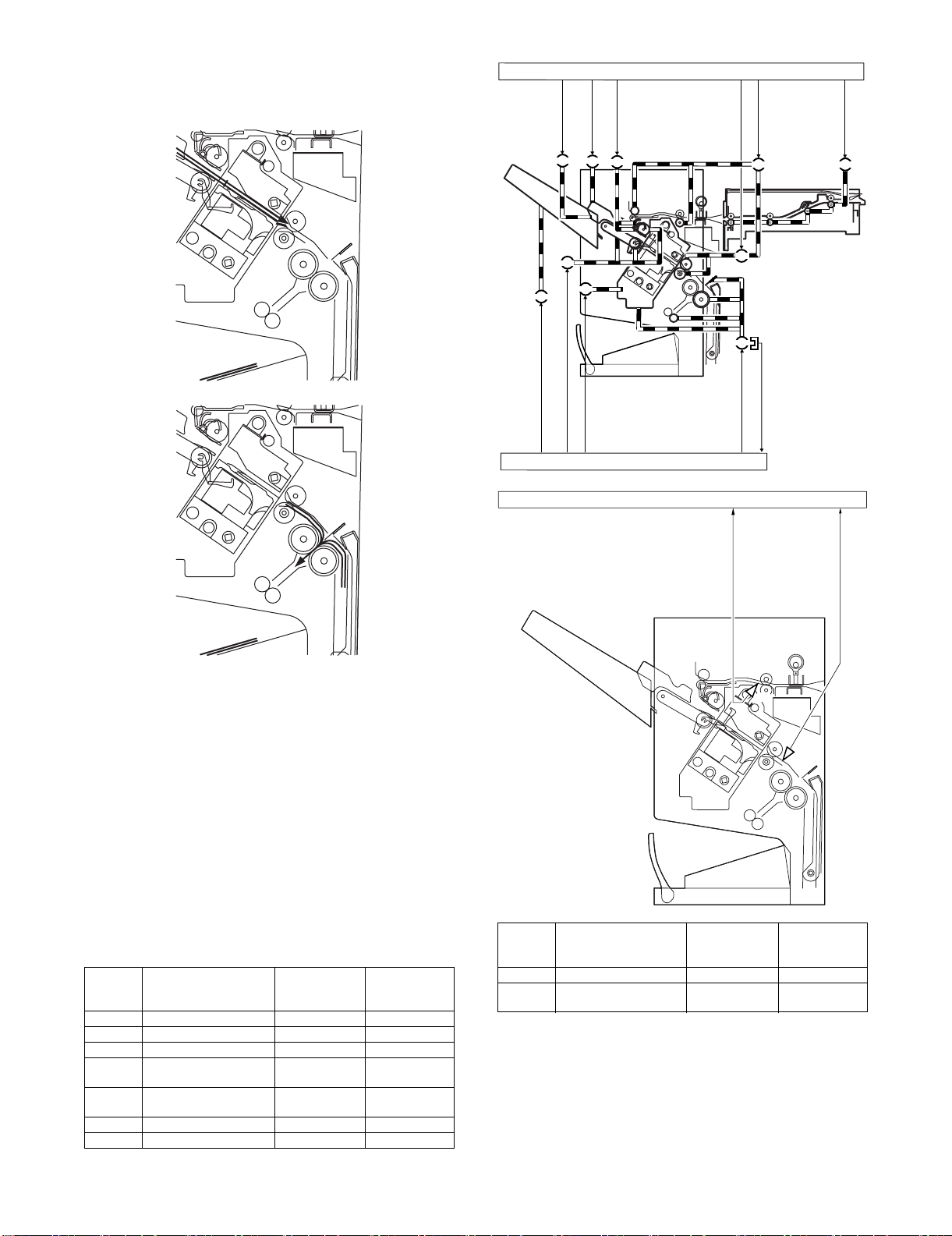
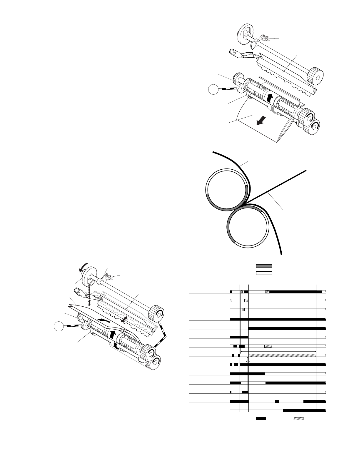
C. Paper Feed System
(1) Outline
The paper feed system feeds a stack of sheets (coming from the
finisher) to the position where the center of the paper stack (stitching position) is aligned to the stapler's staple, allowing the next step
(stitching and folding) to be performed.
When sheets of paper have been stacked and aligned on the processing tray, the paddle motor (FPM) rotates in the reverse direction, causing the swing guide to descend. As the swing guide
descends, the paper stack is sandwiched between the upper and
lower stack delivery rollers. The stack delivery motor (FAM) rotates
in the reverse direction, feeding the paper stack toward the saddle
unit. When the leading edge of the paper stack reaches the binding
position sensor (FFPD), the finisher controller PCB drives the stack
delivery motor (FAM) a specified number of motor pulses to stop
the center of the paper stack (stitching position) at the stapler's staple position. Before the paper stack passes through the stack feed
rollers, the feed motor (FFM) is driven to rotate the stack feed roller
(lower) so that the leading edge of the paper stack is not bent.
Stack feed roller (upper)
Paper pushing plate
Stack feed roller (lower)
Paper fold roller
d. Folding/delivery
The paper pushing plate pushes in the center of the paper stack to
feed it toward the paper fold rollers. Then, the paper fold rollers and
bind delivery rollers deliver the paper stack to the bind tray.
D. Stack Feed System
(1) Outline
The stack feed system feeds the stitched paper stack to the folding
position.
When stitching is complete, the feed motor (FFM) rotates, causing
the stack feed roller (upper) to descend. The paper stack is sandwiched between the stack feed rollers. Then, the bind clutch (FFC)
is turned ON to rotate the feed motor (FFM) in the forward direction, thus feeding the paper stack to the folding position. The feed
amount is equivalent to the number of pulses used to drive the feed
motor (FFM) until the paper stack reaches the folding position.
Stack feed roller (upper)
Feed amount
Bind delivery rollers
Paper fold rollers
MX-FNX2/AR-PN1/MX-RBX1 OPERATIONAL DESCRIPTION 5 – 11
Stack feed roller (lower)
Page 22
E. Fold/Delivery System
Feed motor (FFM)
Bundle exit motor (FAM)
Paddle motor (FPM)
Paddle home position
sensor (FPDHPD)
Bundle roller home position
sensor (FARHPD)
Staple safety switch
(FSSSW)
Staple shift motor (FSM)
Staple motor (FFSM)
Staple drive home position
sensor (FSHPD)
Bookbinding position
sensor (FFPD)
Bookbinding roller home
position sensor (FFRHPD)
Bookbinding clutch (FFC)
Bookbinding home
position sensor (FFHPD)
Bookbinding paper
sensor (FFED)
: CW rotation : CCW rotation
50msec
Staple
Fold, Delivery
13571msec
(1) Outline
The paper fold mechanism consists of a guide plate, paper fold rollers, and a paper pushing plate.
The guide plate, paper fold rollers, and paper pushing plate are
driven by the staple motor (FFSM). The drive force is transferred
with a combination of gears and cams. Motor operation is monitored by the binding lock sensor (FFE).
Until the paper stack reaches the folding position, the guide plate
covers the paper fold rollers to act as a paper path through which a
paper stack is fed to the saddle unit and to prevent a paper stack
from touching the rollers.
A binding home position sensor (FFHPD) is provided to detect the
positions of the paper fold rollers and paper pushing plate.
The paper stack folded in two by the paper fold rollers is delivered
by bind delivery rollers. The bind delivery rollers are also driven by
the staple motor (FFSM).
A bind tray sensor (FFED) is provided on the bind tray to detect
presence/absence of a paper stack; however, it is not used to
detect a jam.
(2) Paper Folding
Paper is folded using paper fold rollers and a paper pushing plate.
Almost concurrently with the start of roller rotation, the paper pushing plate starts operating to push the paper stack into the gap
between the paper fold rollers. When the paper stack is fed about
10 mm with the rotation of the paper fold rollers, the paper pushing
plate returns to the home position. Then, the paper stack is delivered to the bind tray using the paper fold rollers and bind delivery
rollers.
Half the entire surface of each paper fold roller is uncovered
excluding the central area and the area at the left and right ends.
The uncovered surface of the upper paper fold roller comes in
touch with the uncovered surface of the lower paper fold roller only
at the center and left and right ends, allowing a paper stack to be
fed without causing creases. The other half of the upper paper fold
roller that is covered comes in touch with the other half of the lower
paper fold roller that is also covered, allowing a paper stack to be
folded while being fed.
Paper fold roller (upper)
Staple motor
(FFSM)
FFSM
Paper fold roller (lower)
Paper stack
Outlet
Paper stack
Bookbinding home position
sensor (FFHPD)
Paper pushing plate
Inlet
Paper push plate
Paper fold roller (upper)
Staple motor
(FFSM)
Came
Paper stack
FFSM
Paper fold roller (lower)
Sensor flag
Bookbinding home position
sensor (FFHPD)
MX-FNX2/AR-PN1/MX-RBX1 OPERATIONAL DESCRIPTION 5 – 12
Folds/feeds a paper stack.
Feeds a paper stack.
Paper pushing plate
Page 23
F. Punch Unit (AR-PN1A/B/C/D)
Punch motor
(FPNM)
drive signal
Punch controller PCB (1/2)
Waste full detection signal
(LED121,PT131) FPDD
Punch home position sensor detection signal
(FPHPD)
Horizontal registration home position
(FPSHPD)
detection signal
SREGHP
Punch controller PCB (2/2)
Punch motor lock sensor (
FPMCK
)
detection signal
PUNCHCLK
PT1
LED1
2
3
4
5
5
2
3
4
Trailing edge detection signal
(LED5, PT5) FPTD
Horizontal registration detection
signal (LED1 - 4, PT1 - 4)
FPSD1 - 4
Horizontal registration
motor (FPSM) drive signal
PT131
LED121
(1) Basic Operations
a. Outline
The punch unit is an option, and is designed for installation to the
pickup assembly of the finisher.
The punch unit is not equipped with a paper feeding mechanism,
and the sheets from the host machine move through the punch unit
and then the feed system of the finisher. When the trailing edge of a
sheet from the host machine reaches the punch unit, the sheet is
stopped once, and the punch shaft is rotated to punch a hole along
the trailing edge. These operations are controlled with various commands from the finisher controller PCB as well as the commands
from the punch controller PCB.
Punch drive system
Horizontal registration
drive system
Punch controller PCB
Finisher unit control system
The punch motor (FPNM), punch unit, and sensors make up the
punch slide unit, which moves to the front/rear to suit the selected
paper size. The movement to the front/rear is driven by the punch
horizontal registration motor (FPSM). The home position of the
punch slide unit is detected by the punch horizontal registration
home position sensor (FPSHPD), and the punch horizontal registration motor (FPSM) is a stepping motor.
The punch motor (FPNM) and punch horizontal registration motor
(FPSM) are controlled with various commands from the finisher
controller PCB as well as the commands from the punch controller
PCB. The waste paper occurring as the result of punching is collected in the waste paper case. The case is monitored by the
LED121 on the waste full LED PCB and PT131 on the waste full
photosensor PCB (FPDD).
(2) Punching Operation
a. Outline
The punch unit is located in the pickup assembly of the finisher,
and is used to punch holes in sheets that have been sent from the
host machine and stopped inside it. When the trailing edge of a
sheet reaches the punch unit, the inlet roller of the finisher assembly stops the sheet to punch a hole along the trailing edge of the
sheet.
The punch unit consists of a die and hole puncher (punch blade).
The hole puncher is driven by the punch motor (FPNM). It is
attached to the eccentric cam of the punch shaft, and the rotation of
the punch shaft is converted into reciprocating motion for punching
operation.
The punch motor (FPNM) is a DC motor. The home position of the
punch shaft is detected by the punch home position sensor
(FPHPD). To make sure that the punch motor (FPNM), which is a
DC motor, stops exactly at its home position, the punch motor
(FPNM) is stopped in relation to the count of the clock pulses kept
by the punch motor lock sensor (FPMCK). A single punching operation is executed by rotating the punch shaft 180° from its home
position.
As many as five light-receiving transistors (photosensor PCB) are
mounted over the inlet paper path of the punch unit; on the other
hand, as many as five LEDs (LED PCB) are mounted under the
path, together serving as five sensors. The frontmost sensor
(LED5, PT5) is used as a trailing edge sensor (FPTD) to detect the
training edge of sheets, and the remaining four (LED1 through
LED4, PT1 through PT4) are used as horizontal registration sensors (FPSD1 through FPSD4) to detect the rear position of sheets
when punching holes.
MX-FNX2/AR-PN1/MX-RBX1 OPERATIONAL DESCRIPTION 5 – 13
Page 24

b. Punching Operation
(punch shaft at rest/
home position)
(punch shaft CW rotation by 90°/
punch at upper limit)
(punch shaft CW rotation by 180°/
punch back to initial position)
(punch shaft at rest/
home position)
(punch shaft CCW rotation
by 90°/hole made)
(punch shaft CCW rotation by 180°/
end of punching operation)
The hole puncher is driven by the punch motor (FPNM). The home
position for the hole puncher is detected by the punch home position sensor (FPHPD).
The punch unit comes in four types, selected to suit the country of
installation: 2-hole (Punch Unit-J1), 2- and 3-hole (Punch Unit-K1),
or two types of 4-hole (Punch Unit-G1, Punch Unit-H1).
The 2-hole and 4-hole types punch a hole when the punch shaft is
rotated 180° from the home position, causing the punch to make a
single round trip. The 2-/3-hole type punches a hole, but the circumference of the punch shaft is divided into two (half for 2-hole
and the other half for 3-hole).
1) 2-Hole, 4-Hole Type
The home position is identified when the punch home position
sensor (FPHPD) is ON. The punching operation for the first
sheet ends when the punch shaft has rotated 180° and the
punch home position sensor (FPHPD) goes ON; the punching
operation for the second sheet ends when the punch shaft has
rotated 180° in reverse and the punch home position sensor
(FPHPD) goes ON.
<1> A hole is punched along the trailing edge of the 1st sheet.
Sensor flag
Punch home position
sensor (FPHPD)
Punch shaft
<1> A hole is made along the trailing edge of the 1st sheet.
Sensor flag
Punch home position
sensor (FPHPD)
Punch shaft
Eccentric cam
(punch shaft at rest/
Die
Die
home position)
Hole
puncher
Paper
(punch shaft CW rotation
by 90°/hole made)
Waste paper
(punch shaft CW rotation by 180°/
end of punching operation)
While two holes are being made, the 3-hole puncher
makes a single round trip in escape direction.
Eccentric cam
Die
Die
(punch shaft at rest/
home position)
Hole
puncher
Paper
(punch shaft CW rotation
by 90°/hole made)
Waste paper
(punch shaft CW rotation by 180°/
end of punching operation)
<2> A hole is made along the trailing edge of the 2nd sheet.
Sensor flag
Punch home position
sensor (FPHPD)
Punch shaft
Eccentric cam
Die
(punch shaft at rest/
Die
home position)
Hole
puncher
Paper
(punch shaft CW rotation
Waste paper
by 90°/hole made)
(punch shaft CW rotation by 180°/
end of punching operation)
2) 2-/3-Hole Type
The home position is identified when the punch home position
sensor (FPHPD) is ON. To make two holes, the punching operation for the first sheet ends when the punch shaft rotates 180°
(half circumference) and the punch home position sensor
(FPHPD) goes ON. At this time, the 3-hole puncher makes a
single round trip in escape direction (moving up the hole
puncher) on a half circumference of the punch shaft. The
punching operation for the second sheet ends when the punch
shaft has rotated 180° counterclockwise and the punch home
position sensor (FPHPD) goes ON (half circumference).
At this time, the 3-hole puncher makes a single round trip in
escape direction (moving up the hole puncher) on the other
half circumference of the punch shaft.
The punching operation takes place as follows when making
two holes in two sheets of paper:
<2> Holes are made along the trailing edge of the 2nd sheet.
While two hole are being made, the 3-hole puncher makes
a single round trip in escape direction (moving up the hole
puncher).
(punch shaft at rest/
home position)
(punch shaft CCW rotation by
90°/punch at upper limit)
(punch CCW rotation by 180°/
punch back at initial position)
MX-FNX2/AR-PN1/MX-RBX1 OPERATIONAL DESCRIPTION 5 – 14
Page 25
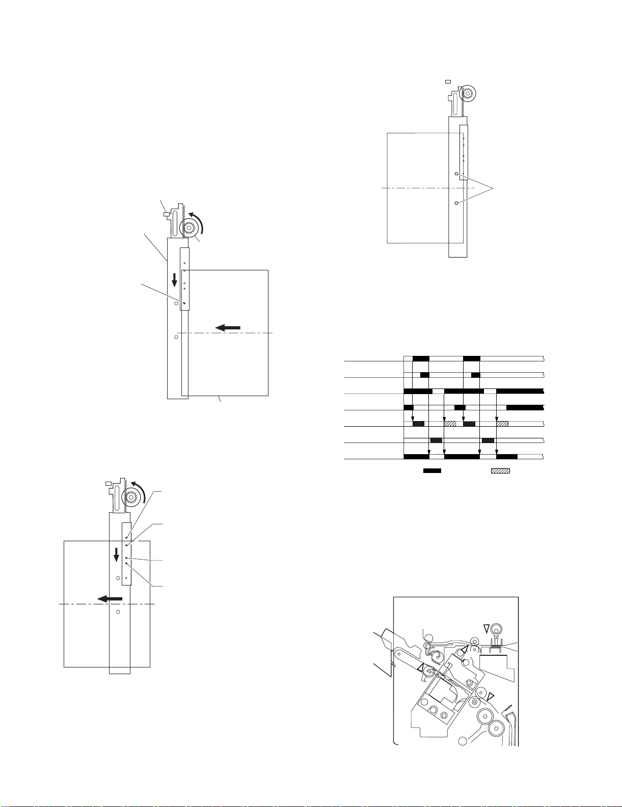
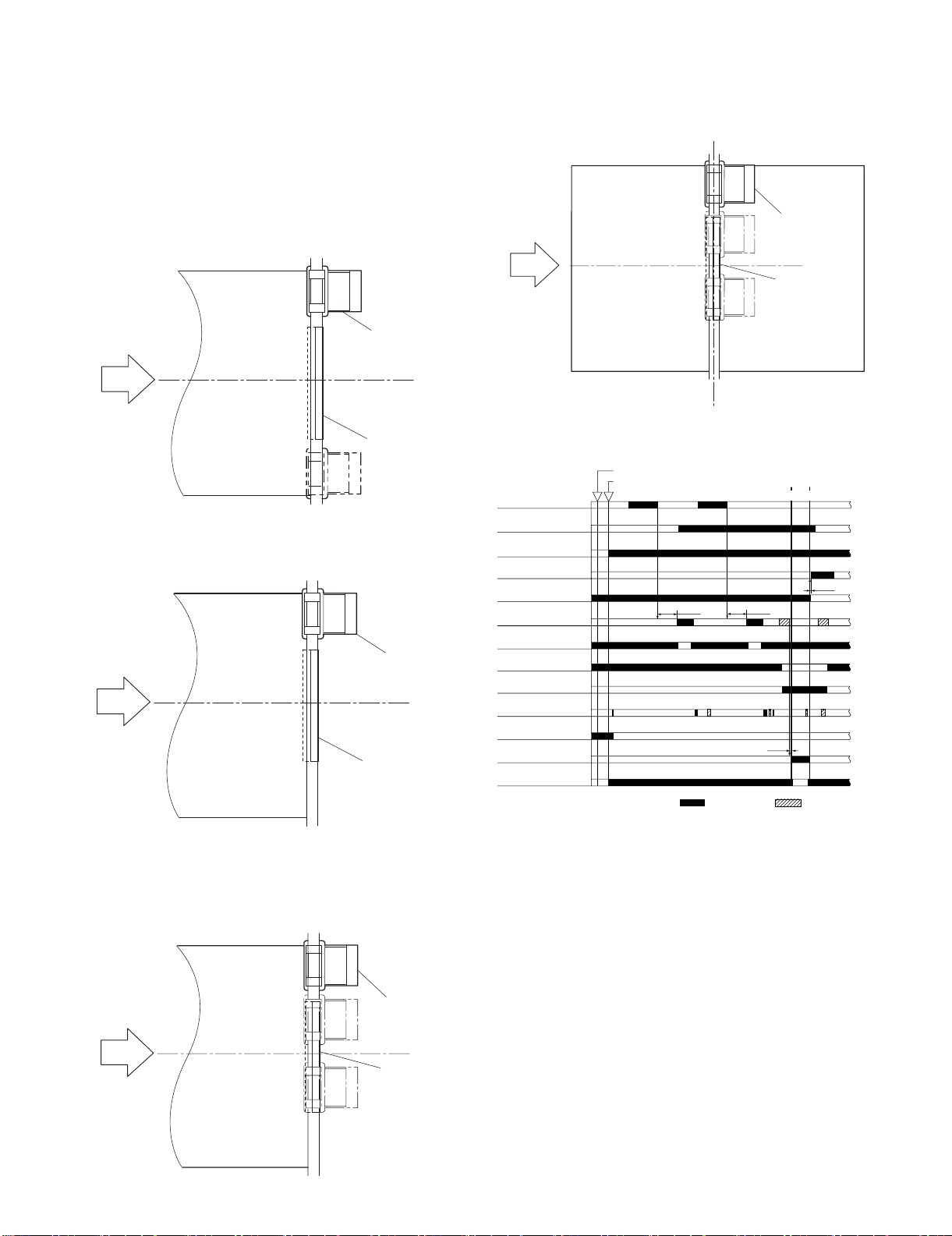
(3) Horizontal Registration Operation
Punch
The horizontal registration drive for the punch slide unit is provided
by the punch horizontal registration motor (FPSM). The home position of the punch slide unit is detected by the punch horizontal registration home position sensor (FPSHPD). The punch slide unit
detects the trailing edge of sheets using the trailing edge sensor
(FPTD) and the horizontal registration sensors (FPSD1 through 4),
and causes a move to a specific position matching the trailing edge
of each sheet (in relation to the size of the sheet).
The horizontal registration operation takes place as follows:
1) When the leading edge of a sheet from the host machine is
detected by the trailing edge sensor (FPTD), the punch horizontal registration motor (FPSM) starts to move the punch
slide unit toward the front.
Punch side resist home position sensor
(FPSHPD)
Punch slide unit
Punch side resist motor
(FPSM)
Trailing edge sensor
(FPTD)
(direction of
paper delivery)
Paper
2) When the horizontal registration sensor (FPSD1 through 4)
suited to the paper size signal from the host machine detects
the rear edge of the sheet, the punch horizontal registration
motor (FPSM) causes a farther move to a specific position,
and stops the punch slide unit.
Horizontal registration sensor 1 (FPSD1);
used to detect the edge of sheets of A3, A4,
8.5" x 11", 11" x 17".
Horizontal registration sensor 2 (FPSD2);
used to detect the edge of sheets of B4, B5,
8.5" x 11"R, 8.5" x 14".
Horizontal registration sensor 3 (FPSD3);
used to detect the edge of sheets of A4R.
Horizontal registration sensor 4 (FPSD4);
used to detect the edge of sheets of B5R.
3) When the trailing edge sensor (FPTD) detects the trailing edge
of the sheet, the drive of the feed motor (FFM) is stopped,
thereby stopping the sheet. Then, the punch motor (FPNM) is
driven to punch holes in the sheet.
4) When the punching operation ends, the feed motor (FFM) of
the fisher unit is driven and, at the same time, the punch horizontal registration motor (FPSM) is rotated in reverse to return
the punch slide unit to its home position.
5) For each sheet that arrives in succession, the punch slide unit
is returned to its home position, and is caused to repeat steps
1 through 4.
Trailing edge sensor
(FPTD)
Horizontal registration
sensor (FPSD1 - 4)
Punch home position
sensor (FPHPD)
Punch horizontal registration
home position sensor (FPSHPD)
Punch horizontal
registration motor (FPSM)
Punch motor (FPNM)
Feed motor (FFM)
: CW rotation : CCW rotation
G. Detecting Jams
(1) Outline
The microprocessor (CPU) on the finisher controller PCB is programmed to check for jams in the finisher/saddle/puncher (option)
at such times as set in advance. It identifies a jam in reference to
the presence/absence of paper at a specific sensor. If a jam is
found, the finisher controller PCB communicates the nature of the
jam to the host machine in the form of a code(which may be
checked in service mode of the host machine).
FAD
FED
: Entry paper sensor
FAD
: Alignment tray sensor
FFPD
: Bookbinding position sensor
FPHPD
: Punch home position sensor
MX-FNX2/AR-PN1/MX-RBX1 OPERATIONAL DESCRIPTION 5 – 15
FPHPD
FED
FFPD
Page 26
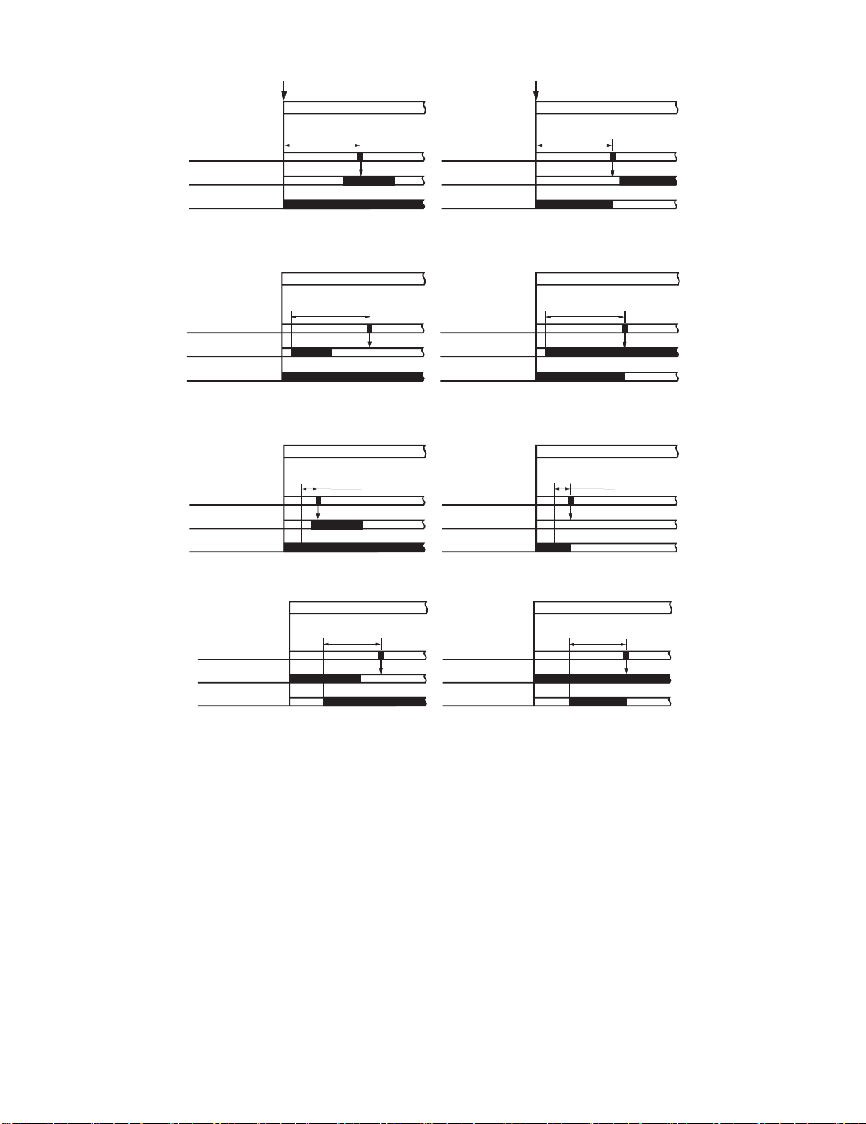
a. Inlet Paper Sensor (FED) Delay Jam
Host machine delivery signal
Host machine delivery signal
Jam check
Entry paper sensor
(FED)
Feed motor (FFM)
approx. 1.0sec.
*
Normal
Jam check
Entry paper sensor
(FED)
Feed motor (FFM)
approx. 1.0sec.
*
Jam
* Variable depending on the paper size. (Because the paper feed speed may differ according to the paper size. (A4:1.0 sec.))
b. Inlet Paper Sensor (FED) Stationary Jam
Jam check
Entry paper sensor
(FED)
Feed motor (FFM)
approx. 1.4sec.*
Normal
Jam check
Entry paper sensor
(FED)
Feed motor (FFM)
approx. 1.4sec.*
Jam
* Variable depending on the paper size. (Because the paper feed speed may differ according to the paper size. (A4:1.4 sec.))
c. Binding Position Sensor (FFPD) Delay Jam
Jam check
Binding position
sensor (FFPD)
Stack delivery motor
(FAM)
1080 ms
Normal
Jam check
Binding position
sensor (FFPD)
Stack delivery motor
(FAM)
1080 ms
Jam
d. Binding Position Sensor (FFPD) Stationary Jam
Jam check
Binding position
sensor (FFPD)
Staple motor (FFSM)
approx. 16.2sec. approx.16.2sec.
Normal
Jam check
Binding position
sensor (FFPD)
Staple motor (FFSM)
Jam
e. Power-On Jam
Paper is detected inside the finisher at power-on or when the door is closed.
f. Door Open Jam
The finisher is disconnected from its host machine or the front door, or the upper cover is opened while the system is in operation (paper on the
move).
g. Staple Jam
The staple drive home position sensor (FSHPD) does not go OFF 600 msec after the stapler is driven. Or, it does not return to its home position
(where the sensor goes ON).
MX-FNX2/AR-PN1/MX-RBX1 OPERATIONAL DESCRIPTION 5 – 16
Page 27
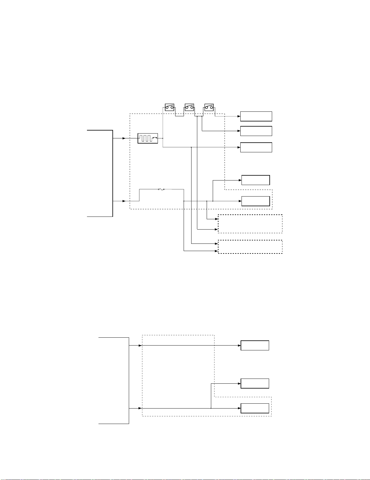
H. Power Supply System
(1) Finisher/Saddle Assembly
a. Outline
When the host machine is turned on, it supplies the finisher controller PCB with 24VDC and 5VDC. 24VDC is for the motors and clutches.
24VDC and 5VDC are also supplied as a relay pass drive, 5VDC is used to drive sensors and ICs on PCBs.
If a punch unit (option) is installed, power is also supplied to the punch controller PCB.
Some of 24 VDC used to drive motors is cut off when the joint switch (FJSW), front door switch (FFDDW), or stapler safety switch (FSSSW) is
open.
The block diagram of the power supply system is below.
Front door switch
Joint switch
(FJSW)
(FFDDW)
Stapler safety switch
(FSSSW)
24V
Motor
Host
machine
24VC
5VDC
Circuit Breaker
(CB1)
Finisher
controller PCB
Circuit protector
24V
24V
(CP2)
Punch controller PCB
(punch unit; option)
Relay interface PCB
5V
5V
Logic system
Motor
Clutch
Sensor
b. Protective Mechanisms
A circuit breaker (CB1) is monitored to protect the 24 VDC system used to drive the motors against overcurrent. The 24-V system used to drive
the feed motor (FFM), paddle motor (FPM), and stack delivery motor (FAM) is equipped with a fuse which melts in the presence of overcurrent.
(2) Punch Unit (option)
a. Outline
When the host machine is turned on, the punch unit is supplied by the finisher controller PCB with 24-V and 5-V power.
The 24-V power is used to drive the motors, while the 5-V power is used by sensors and the ICs on the punch controller PCB.
The 24-V power to the motors will be cut off when the joint switch (FJSW) or the front door switch (FFDDW) of the finisher unit is open.
The following is a block diagram for the power supply system:
Finisher
controller
PCB
24 V
Punch controller PCB
5V
24 V
5V
5V
Motors
Sensors
Logic system
b. Protective Mechanisms
The 24-V system used to drive the punch motor (FPNM) and the punch horizontal registration motor (FPSM) is equipped with a built-in fuse
which melts in the presence of overcurrent.
MX-FNX2/AR-PN1/MX-RBX1 OPERATIONAL DESCRIPTION 5 – 17
Page 28

âºíuÇ´
[6] DISASSEMBLY AND
ASSEMBLY
1) Turn off the host machine, disconnect the saddle stitch finisher
connctor.
2) Free the lock, and remove the saddle stitch finisher from the
host machine.
1. Saddle stitch finiser (MX-FNX2)
A. Externals and Controls
(1) Delivery tray
1) Remove the delivery tray.
2) Remove the front cover.
Service Manual
(3) Rear Cover
1) Remove the rear cover.
(2) Front Cover
1) Open the front door, and remove the knob.
1
2
(4) Upper Cover
1) Remove the front cover. (See (2).)
2) Remove the rear cover. (See (3).)
3) Open the upper cover, and remove the cover band.
2
1
4) Detach the processing cover, and remove the upper cover.
2
1
MX-FNX2/AR-PN1/MX-RBX1 DISASSEMBLY AND ASSEMBLY 6 – 1
Page 29
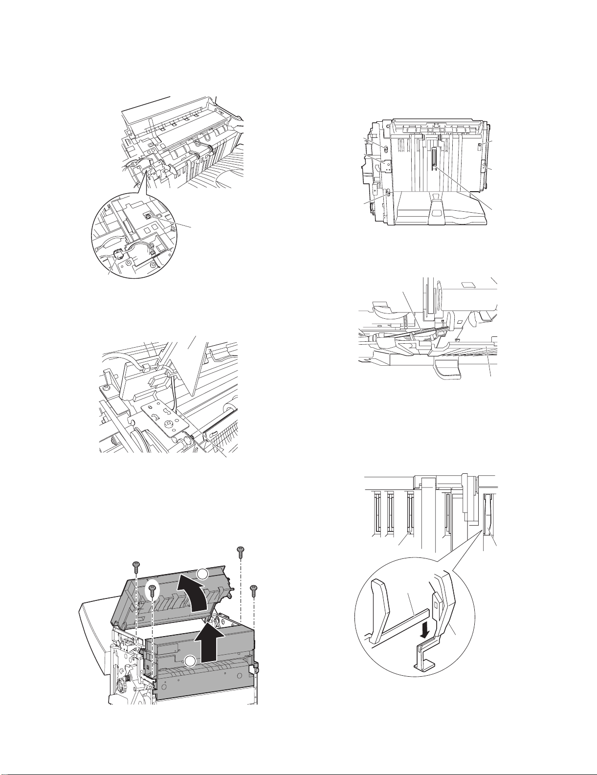
(5) Processing Tray Upper Cover
[6]
[5]
[5]
[6]
1) Remove the front cover. (See (2).)
2) Remove the rear cover. (See (3).)
3) Remove the upper cover. (See (4).)
4) Disconnect the connector [1] and remove the screw [2].
(7) Removing the Saddle Guide
1) Remove the delivery tray. (See (1).)
2) Remove the front cover. (See (2).)
3) Remove the rear cover. (See (3).)
4) Free the delivery tray support plate (front) [1] and the delivery
tray support plate (rear) [2] to the outside from the rail grooves.
5) Remove the four screws [3].
[2]
[1]
5) While lifting the processing tray cover [3], disconnect the connector [4], then remove the processing tray upper cover [3].
[3]
[4]
[3]
[3]
[2]
[1]
[3]
6) Shift the side guide [4] lightly to the front, and free the engagement of the paper surface detecting lever (rear) [5]; then,
detach the side guide [4].
[3]
[5]
[4]
NOTE: Be sure to mount the side guide after securely fitting the
paper surface detecting lever (rear) [5] in the groove of the
paper surface detecting lever (middle) [6].
After completion of mounting, push the paper surface
detecting lever several times to make sure that side guide
is mounted securely.
(6) Upper Right Cover, Middle Right Cover
1) Remove the front cover. (See (2).)
2) Remove the rear cover. (See (3).)
3) Open the upper cover, then remove the upper right cover and
the middle right cover.
1
2
MX-FNX2/AR-PN1/MX-RBX1 DISASSEMBLY AND ASSEMBLY 6 – 2
Page 30

B. Feeding System
[2]
[5]
[3]
[4]
[1]
[14]
[15]
[13]
(1) Removing the Stapler Unit
1) Open the front door.
2) Slide out the stapler unit while pressing the stopper.
1
3
2
NOTE: Do not remove the stapler stapler frame shaft. If removed,
the position where the staple driver (lower unit of the stapler) [4] shoots stables will shift from the position where the
staple clincher (upper unit of the stapler) [5] receives staples.
[5]
[4]
1) Detach the gear cover [2] from the staple driver [1].
2) Remove the E-ring [3] to detach the side cover [5] of the staple
clincher [4].
3) Remove the two E-rings [6] to remove the staple jam releasing
gear [7], timing belt [8], and relay gear 1 [9]. Remove the
spacer and spring at the back of the staple jam releasing gear.
4) Remove the screw [10] and spring [11] to remove the belt tensioner [12].
[7]
[8]
[6]
[11]
[9]
[10]
(2) Adjusting the Stapler Phase
When the gears or timing belt at the front of the stapler is replaced
or removed for some reason, the staple shooting timing of the
(lower unit of the stapler) does not match the staple bending timing
of the staple clincher (upper unit of the stapler). Adjust the stapler
phase following the procedure described below.
Gear
Timing belt
Gear
[12]
5) Remove the timing belt [13].
6) Remove the E-ring [14] to remove the staple position check
gear [15].
7) Turn the gear [16] to align the round hole in the staple driver
gear with the round hole [17] at the back.
[16]
[17]
MX-FNX2/AR-PN1/MX-RBX1 DISASSEMBLY AND ASSEMBLY 6 – 3
Page 31

8) Insert a pin [18] with a diameter of approximately 2 mm
[25]
[26]
[27]
(use of a 2 mm Allen wrench is recommended) in the round
hole to secure the gear.
[18]
9) Turn the gear [19] to align the round hole in the staple clincher
cam with the round hole [20] at the back.
12) Mount the staple position check gear [27] so that the blue mark
[25] on the staple position check gear is aligned with the round
hole [26] in the frame.
[19]
[20]
10) Insert a pin [21] with a diameter of approximately 2 mm (use of
a 2 mm Allen wrench is recommended) in the round hole to
secure the gear.
The position where the blue mark is aligned with the round
hole is the home position for stapling. If the staple jam cancel
dial is turned for some reason, the home position deviates,
making it impossible to remove the stapler cartridge. If such a
case, the gear can be returned to the home position by checking blue mark position. Therefore, it is necessary to mount the
gear at the correct position.
13) Remove the pin securing the gear to the cam.
14) Assemble the spring [28], spacer [29], staple jam releasing
gear [30], timing belt [31], and relay gear [32] and secure them
with the E-ring [33].
[28]
[31]
[29]
[30]
[32]
[33]
(3) Adjusting the Phase of the Gear in the Saddle Unit
If the gears at the front of the saddle unit or the paper fold rollers in
the sale unit are replaced or removed for some reason, adjust the
gear phase following the procedure described below.
1) The paper fold rollers [1] and saddle cam [2] must be positioned as shown below.
[21]
11) With the gears and cam fixed, install the timing belt [22] on
gears [23] and [24].
[23]
[22]
[24]
MX-FNX2/AR-PN1/MX-RBX1 DISASSEMBLY AND ASSEMBLY 6 – 4
[2]
[1]
Page 32

2) With the paper fold rollers and saddle cam positioned as
shown, mount gears as shown below.
• Align the ▲ mark (either of two ▲ marks) on the saddle cam
drive gear [3] with the ▲ mark on the relay gear [4] (on the
half of the periphery where gears with a smaller face width
are arranged).
• With the ▲ mark on the saddle cam drive gear [3] aligned
with the ▲ mark on the relay gear [4], align the other ▲ mark
on the relay gear withy the rib of the paper folding roller drive
gear [5].
[3]
7) Remove the three screws [9], and slide out the stapler unit [10]
slightly to the front.
8) Slide out the saddle unit [11] to the front.
[10] [9]
[4]
[5]
(4) Saddle Unit
1) Remove the front cover. (See A.(2).)
2) Remove the rear cover. (See A.(3).)
3) Open the jam removal cover [1]; then, remove the two screws
[2] and the right stay [3].
[3]
[2]
[2]
[1]
4) Turn the fold jam releasing dial assembly [4] to move the paper
retaining plate assembly [5] to the inside.
[5]
[9] [11]
(5) Processing Tray Assembly
1) Remove the processing tray upper cover. (See A.(5).)
2) Remove the side guide. (See A.(7).)
3) Remove the two screws [1], and disconnect the five connectors [2].
[1]
[2]
[2] [2]
4) Pull the processing stopper base [3] to the front, and free the
claw [5] at the front and the claw [6] at the rear of the processing stopper [4].
[6]
[4]
[1]
[5]
[4]
[4]
5) Remove the stop ring [6], and detach the timing belt [7].
6) Disconnect the two connectors [8].
[6]
[7]
[8]
MX-FNX2/AR-PN1/MX-RBX1 DISASSEMBLY AND ASSEMBLY 6 – 5
[3]
Page 33

5) Disconnect the three connectors [7].
[3]
[4]
[4]
6) Release the two claws [8] of the harness retainer, and detach
the motor harness [9].
[9]
(6) Paddle Assembly
1) Remove the processing tray assembly. (See B.(3).)
2) Place the processing tray assembly [1] as shown.
NOTE: Be sure to take care not to damage the aligning plate
[2].
[1]
[2]
[8]
[7]
7) Remove the stop ring [10], and detach the timing belt [11].
8) Disconnect the connector [12], and free the harness [14] from
the edge saddle [13].
[12]
[11]
[10]
[14]
[13]
3) Detach the timing belt [3], and remove the two screws [4].
9) Remove the two screws [15], and slide the processing tray
assembly [16] to the rear; then lift it to detach.
[16]
[15]
MX-FNX2/AR-PN1/MX-RBX1 DISASSEMBLY AND ASSEMBLY 6 – 6
4) Separate the processing tray assembly [5] and the paddle
assembly [6] as shown.
[6]
[5]
Page 34

(7) Staple/Fold Drive Unit
[5]
[5]
[3]
[4]
[6]
[1]
[2]
1) Open the front door, and slide out the stapler unit slightly to the
front.
10) Disconnect the two connectors [18], and free the harness [20]
from the edge saddle [19].
[18]
1
2
2) Remove the screw [3], and detach the interface retainer [4].
3) Free the six harness retainers [5], and disconnect the connector [6].
4) Free the harness [7] from the harness retainer [5].
5) Free the harness [7] from the edge saddle [8]; then, disconnect
the two connectors [9].
[9]
[8]
[7]
[5]
[6]
[7]
[3]
[5]
[7]
[20]
[18]
[19]
11) Remove the three screws [21].
[21]
[21]
[21]
12) Remove the screw [22], and detach the staple/fold drive unit
[23].
[5] [7] [5]
[4]
6) Release the harness retainer [10], and disconnect the connector [11].
7) Free the harness [12] from the harness retainer [10].
[22]
[23]
8) Free the harness [12] for the edge saddle [13]; and disconnect
the two connectors [14].
[14]
[11]
(8) Feed Motor Unit
1) Remove the rear cover. (See A.(3).)
2) Open the harness retainer [1], and disconnect the two connectors [2].
[13]
[12]
[10]
3) Remove the screw [3], and detach the harness guide [4].
4) Remove the three screws [5], and detach the feed motor unit
[6].
9) Remove the screw [15], and free the claw [17] of the harness
guide from the long angle [16] of the base plate.
[16]
[15]
[17]
MX-FNX2/AR-PN1/MX-RBX1 DISASSEMBLY AND ASSEMBLY 6 – 7
Page 35

(9) Feed Roller
1) Remove the upper cover. (See A.(4).)
2) Remove the upper right cover assembly. (See A.(6).)
3) Remove the feed motor unit. (See B.(6).)
4) Remove the screw [1].
5) Remove the stop ring [2], and detach the bushing [3].
[3]
[1]
[2]
6) Remove the two screws [4].
11) Remove the feed roller [12].
[12]
(10) Stack Delivery Roller (Upper)
1) Remove the paddle assembly. (See B.(4).)
2) Place the paddle assembly [1] as shown.
[1]
[4]
7) Remove the gear [5], and detach the gear [6] while spreading
the claw.
8) Remove the stop ring [7], and detach the bushing [8].
9) Remove the screw [9], and detach the inlet sensor [10].
10) Remove the lower paper guide [11].
[5]
[8]
[9]
3) Turn the gear [2] in the direction of the arrow to move up the
stack delivery roller assembly (upper) [3].
[3]
[2]
4) Push up the stack delivery roller (upper) [4] from below to free
the stack deliver roller (upper) [4] from the shaft [5].
[10]
[11]
[7]
[6]
MX-FNX2/AR-PN1/MX-RBX1 DISASSEMBLY AND ASSEMBLY 6 – 8
[4]
[5]
Page 36

5) Shift up the stack delivery roller (upper) [4], and then push it
[5]
[7]
[6]
down to detach the stack deliver roller (upper) [4].
6) Likewise, remove the stack delivery roller (upper) [6] at the
front.
[6]
[4]
(11) Paddle
1) Remove the paddle assembly. (See B.(4).)
2) Place the paddle assembly [1] as shown.
[1]
3) Turn the gear [2] in the direction of the arrow to move up the
stack delivery roller assembly (upper) [3].
5) Push up the safety guide [4] from below to free the safety
guide [4] from the shaft [5].
[4]
[5]
6) Remove the paddle [6] in the direction of the arrow.
7) Likewise, remove the other paddle.
[6]
(12) Stack Delivery Roller (Lower)/Delivery Belt
1) Remove paddle assembly, and separate it from the processing
tray assembly. (See B.(4).)
2) Slide the aligning plate (front) [2] and the aligning plate (rear)
[3] of the processing tray assembly [1] by sliding them to the
outside.
[3]
[2]
4) Push up the safety guide [4] from below to free one side of the
safety guide [4] from the shaft [5].
[1]
[3]
[2]
3) Remove the processing tray stopper [4].
[4]
4) Remove the screw [5], and detach the paper guide (front) [7]
while freeing the two claws [6].
[5]
[4]
MX-FNX2/AR-PN1/MX-RBX1 DISASSEMBLY AND ASSEMBLY 6 – 9
Page 37

5) Remove the screw [8]; then, while freeing the claw [9], detach
[2]
[1]
[1]
[4]
[1]
[3]
[2]
[6]
[7]
the paper guide (rear) [10].
[8]
[10]
[9]
6) Remove the two stop rings [11]; then, move the two bushings
[12] to the inside.
C. PCBs
(1) Finisher Controller PCB
1) Remove the rear cover. (See A.(3).)
2) Disconnect the 17 connectors [1], and remove the screw [2].
3) Free the PCB retainer [3], and detach the finisher controller
PCB [4].
[12]
[11]
[11]
[12]
7) Remove the four screws [13]; then, lift the stack delivery roller
assembly (lower) [14] to detach.
[13]
[14]
8) Remove the stack delivery roller (lower) [15] and the two delivery belts [16].
[13]
[16]
(2) Slide Home Position PCB
1) Open the front door, and turn the tab [2] on the stapler slide in
the direction of the arrow to slide the stapler to the frontmost
point.
2) Remove the stapler unit. (See B.(1).)
2
1
3) Place the stapler unit [3] as shown.
4) Remove the two screws [4], and detach the guide [5].
[3]
[4]
[5]
[15]
NOTE: Be sure to mount them so that the edges [17] of the claws
of the delivery belts are flush.
[17]
MX-FNX2/AR-PN1/MX-RBX1 DISASSEMBLY AND ASSEMBLY 6 – 10
[4]
5) Turn the tab [2] on the stapler side in the direction of the arrow
so that that the fixing screw [7] of the slide home position PCB
[6] is in view through the round hole.
6) Remove the fixing screw [7].
Page 38

7) Disconnect the connector [8].
8) Remove the flexible cable retainer [9].
9) Free the lock [10] of the connector in the direction of the arrow;
then, detach the flexible cable [11], and then detach the side
home position PCB [12].
(2) Paper transport unit exit sensor
1) Remove the paper pass unit.
2) Remove the bracket, and remove the paper transport unit exit
sensor.
[8]
[6]
[10]
[11]
[9]
2. Paper Transport Section (MX-RBX1)
A. Paper Pass Unit
1) Pull out the paper pass unit, and remove the screw.
2) Free the lock, to remove the paper pass unit.
(3) Upper Guide Flapper
1) Remove the paper pass unit.
2) Open the upper transport unit, remove each parts, and remove
the reverse gate.
1
2
3
(4) Interface Fan
1) Remove the paper pass unit.
2) Remove the bottom cover.
(1) Paper transport unit entry sensor
1) Remove the paper pass unit.
2) Remove the paper transport unit entry sensor.
MX-FNX2/AR-PN1/MX-RBX1 DISASSEMBLY AND ASSEMBLY 6 – 11
3) Remove the clamps, and disconnect the connector then
remove the interface fan.
* Install the interface fan so as the side with the label (A)
comes to the direction illustrated.
3
2
2
1
Page 39

(5) Interface Transport Motor
22mm
1) Remove the paper pass unit.
2) Remove the bottom cover. (See (4).)
3) Disconnect the connector, then remove the interface transport
motor.
* Adjust so that the distance between the lower guide and the
upper guide flapper is 22mm with the solenoid plunger
pushed in. Install the entry reverse pass solenoid..
1
3
(6) Entry Reverse Pass Solenoid.
1) Remove the paper pass unit.
2) Remove the bottom cover. (See (4).)
3) Remove the front cover.
4) Remove the solenoid unit
2
(7) Entry Roller
1) Remove the paper pass unit.
2) Remove the interface transport motor. (See (4).)
3) Remove the front cover. (See (6).)
4) Remove the stopper band, and the bracket, then remove the
upper guide unit.
1
3
2
2
* When installing, adjust so that the solenoid is fit with the
bracket ±adjustment reference. If the upper guide unit magnet lifts up, adjust the bracket for the magnet not to lift up.
1
2
5) Remove each parts, then remove the entry reverse pass solenoid.
MX-FNX2/AR-PN1/MX-RBX1 DISASSEMBLY AND ASSEMBLY 6 – 12
Adjustment
reference
± 0.5
5) Remove each parts, then remove the entry roller.
Page 40

(8) Post Entry Roller
1) Remove the paper pass unit.
2) Remove the bottom cover. (See (4).)
3) Remove the front cover. (See (6).)
4) Remove the upper guide unit. (See (7).)
5) Remove the bracket, and remove the post entry roller unit.
6) Remove each parts, and remove the post entry roller.
(10) Exit Roller
1) Remove the paper pass unit.
2) Remove the bottom cover. (See (4).)
3) Remove the front cover (See (6).)
4) Remove the upper guide unit. (See (7).)
5) Remove the drawer bracket.
Remove each parts and remove the exit roller.
B. Reverse Tray Unit
(1) Reverse Flapper
1) Remove the paper pass unit.
2) Remove the reverse tray.
(9) Pre Entry Roller
1) Remove the paper pass unit.
2) Remove the bottom cover. (See (4).)
3) Remove the front cover. (See (6).)
4) Remove the upper guide unit. (See (7).)
5) Remove each parts, and remove the pre entry roller.
3) Remove each parts, and remove the reverse flapper.
MX-FNX2/AR-PN1/MX-RBX1 DISASSEMBLY AND ASSEMBLY 6 – 13
Page 41

C. Left Cabinet Unit
(1) Interface Transport Unit Cover Detection Sensor
1) Remove the paper pass unit.
2) Remove the reverse tray. (See B.(1).)
3) Free the lock, then remove the saddle stitch finisher.
(2) Paper Pass PCB
1) Remove the paper pass unit.
2) Remove the reverse tray. (See B.(1))
3) Remove the left cover. (See C.(1).)
4) Remove allen screw, remove the interface PCB, then remove
the connector.
4) Remove the left cover.
5) Disconnect the connector, and the sensor bracket. Remove
the interface transport unit cover detection sensor.
2
3
1
4
3. Punch Unit (AR-PN1A/B/C/D)
A. Punch Driving System
(1) Removing the Punch Motor
1) Remove the two screws [1].
2) Disconnect the connector [2] to remove the punch motor [3].
[2]
[1]
[3]
(2) Removing the Punch Horizontal Registration
Motor
1) Disconnect connector [1].
2) Remove the harness [3] from the harness guide [2].
3) Remove the two screws [4] to remove the punch horizontal
registration motor [5].
[4]
[3]
[1]
[5]
[2]
MX-FNX2/AR-PN1/MX-RBX1 DISASSEMBLY AND ASSEMBLY 6 – 14
Page 42

(3) Removing the Punch Unit
1) Remove the waste case.
2) Remove the screw [1] to detach the jam processing cover [2].
7) Remove the screw [9] and washer [10].
8) Disconnect the connector [11].
9) Remove the two screws [12] to detach the base cover [13].
[1]
3) Disconnect the connector [3].
4) Remove the harness [5] from the harness guide [4].
[2]
[3]
[5]
[4]
[11]
[9]
[10]
[13]
[12]
5) Disconnect the connector [6].
6) Remove the screw [7] and sensor support plate [8].
[6]
[8]
[7]
10) Remove the four screws [14] to remove the upper transmission
sensor unit [15] and lower transmission sensor [16].
[15]
[14] [14] [14]
[16]
MX-FNX2/AR-PN1/MX-RBX1 DISASSEMBLY AND ASSEMBLY 6 – 15
Page 43

11) Remove the punch unit [18] from the punch horizontal registration motor assembly [17].
4) Disconnect the connector [5] to remove the photosensor PCB
[6].
[17]
[18]
B. PCBs
(1) Punch Controller PCB
1) Remove the two screws [1].
2) Disconnect the five connectors [2] to remove the punch controller PCB [3].
[2]
[3]
[2]
[6]
[5]
(3) Removing the LED PCB
1) Remove the punch waste case.
2) Disconnect connector [1].
3) Remove the harness [3] from the harness guide [2].
[1]
[3]
[2]
[1]
(2) Horizontal Registration Photosensor PCB
1) Remove the punch motor. (See A.(1).)
2) Remove the screw [1].
3) Remove the harness [3] from the harness guide [2] on the
PCB, then detach the PCB cover [4].
[1]
[4]
[2]
4) Remove the screw [4] and washer [5].
5) Disconnect the connector [6].
6) Remove the screw [7] to detach the base cover [8].
[4]
[5]
[8]
[6]
[7]
[3]
[2]
MX-FNX2/AR-PN1/MX-RBX1 DISASSEMBLY AND ASSEMBLY 6 – 16
Page 44

7) Remove the screw [9].
8) Disconnect the connector [10] to remove the LED PCB [11].
[9]
[11]
[10]
(4) Waste-Full Photosensor PCB
1) Remove the punch controller PCB.
2) Remove the two screws [1] to remove the PCB film [2].
[2]
[1]
[3]
3) Disconnect the connector [3] to remove the waste-full photosensor PCB [4].
[2]
[1]
(5) Waste Full LED PCB
1) Remove the screw [1].
2) Disconnect the connector [2] to remove the waste-full LED
PCB [3].
[3]
[4]
MX-FNX2/AR-PN1/MX-RBX1 DISASSEMBLY AND ASSEMBLY 6 – 17
Page 45

âºíuÇ´
[7] MAINTENANCE
Service Manual
1. Maintenance System Table
✕: Check (Clean, replace, or adjust as necessary.) {: Clean ▲: Replace U: Adjust ✩: Lubricate : Move position
No. Part name When calling
1 Transport rollers {{
2 Transport paper guides {{
3Gears ✕✕
4Belts ✕✕
5 Paddle ✕ { Replacement reference: Replace at every 1000K of
6Sensors ✕✕
7 Discharge brush ✕✕
8 Staple unit Replacement reference: Replace the unit at every 100K staple.
9 Punch unit Replacement reference: Replace the unit at every 1000K.
10 Staple cartridge User replacement for every 5000pcs.
111110
1
9
11
181511111
Follows the cycle of the main
unit.
11 1111
6
6
9
Remark
the finisher paper exit count value.
6
6
6
6
6
7
6
6
6
10
8
6
6
6
6
6
6
6
6
6
6
6
6
6
6
6
MX-FNX2/AR-PN1/MX-RBX1 MAINTENANCE 7 – 1
Page 46

ON
12345678
ON
1234
âºíuÇ´
[8] ADJUSTMENTS
1. Finisher/saddle unit
A. Adjusting the Folding Position
The folding position is adjusted by matching it with the stapling
position.
If you have replaced the finisher controller PCB, you must transfer
the existing settings to the new PCB. Perform the following if the
folding position must be adjusted for some reason.
NOTE: Both the folding and stapling positions may deviate for
some type of paper. In such a case, change the "middle
stapling position" in the user mode of the host machine.
1) Set SW1 on the finisher controller PCB as follows:
ON
12345678
2) Adjust the folding position by pressing the PSW1 or PSW2 on
the finisher controller PCB a required number of times. Pressing the switch once moves the folding position about 0.16 mm.
• To move the folding position in the "-" direction, press the
PSW1.
• To move the folding position in the "+" direction, press the
PSW2.
• Pressing the PSW1 and PSW2 at the same time clears the
adjustment value.
- direction
+ direction
2) Adjust the stapling position by pressing the PSW1 or PSW2 on
Service Manual
the finisher controller PCB a required number of times. Pressing the switch once moves the stapling position about 0.14
mm.
• To move the stapling position in the "-" direction, press the
PSW1.
• To move the stapling position in the "+" direction, press the
PSW2.
• Pressing the PSW1 and PSW2 at the same time clears the
adjustment value.
- direction
3) When adjustment of the stapling position is complete, set all
bits of the SW1 on the finisher controller PCB to OFF.
4) Enter the bind mode of the host machine and check whether
the stapling position is adjusted properly. If adjusted improperly, adjust the stapling position again.
+ direction
C. One-page exit mode
This mode is used to increase the accuracy of paper alignment in
the simple load offset mode by discharging paper one by one to the
offset tray.
1) Set the SW1 of the finisher control PWB as shown below.
3) When adjustment of the folding position is complete, set all bits
of the SW1 on the finisher controller PCB to OFF.
4) Enter the bind mode of the host machine and check whether
the folding position is adjusted properly. If adjusted improperly,
adjust the folding position again.
B. Adjusting the Middle 2-Point Stapling Position
The stapling position is adjusted by matching it with the folding
position.
● This adjustment is necessary:
• If you have replaced the finisher controller PCB.
• If the stapling position must be adjusted for some reason.
NOTE: Both the folding and stapling positions may deviate for
some type of paper. In such a case, change the "middle
stapling position" in the user mode of the host machine.
1) Set SW1 on the finisher controller PCB as follows:
ON
12345678
2) Turn on the power.
2. Punch unit (option)
A. Adjusting the Punch Hole Position
This adjustment is available only in the diagnostic mode (Sim 3-10)
of the host machine. The range of punch hole displacement is
between 3 and -3 in 1-mm increments. A higher setting will move
the punch hole toward the leading edge of sheet.
B. Adjusting the Sensor Output
Perform the following when the punch controller PCB, horizontal
registration sensor (photosensor PCB/LED PCB), or waste full sensor (waste full photosensor PCB/waste full LED PCB) has been
replaced.
1) Shift bits 1 through 4 on the punch controller PCB as follows:
2) Press SW1002 or SW1003 on the punch controller PCB. A
press will automatically adjust the sensor output.
• The adjustment is over when all LEDs on the punch control-
ler PCB are ON: LED1001, LED1002, LED1003.
3) Shift all bits of DIPSW1001 to OFF.
MX-FNX2/AR-PN1/MX-RBX1 ADJUSTMENTS 8 – 1
Page 47

C. Registering the Number of Punch Hole
Perform the following to register the type of punch unit (number of
holes) used to the IC on the punch controller PCB for identification
by the finisher. Be sure to register the type whenever you have
replaced the punch controller PCB.
1) Set bits 1 through 4 on the DIPSW1001 on the punch controller PCB as follows:
ON
1234
2) Press SW1002 on the punch controller PCB to select the
appropriate number of punch holes.
• Each press on SW1002 moves the selection through the fol-
lowing (repeatedly from top to bottom).
Number of punch holes LED1001 LED1002 LED1003
2 holes (Punch Unit-J1) ON OFF OFF
2/3 holes (Punch Unit-K1) ON ON OFF
4 holes (Punch Unit-G1) OFF ON OFF
4 holes (Punch Unit-H1) OFF OFF ON
3) Press SW1003 on the punch controller PCB twice. The
presses will store the selected number of punch holes on the
punch controller PCB.
• A single press on SW1003 will cause the LED indication to
flash; another press on SW1003 will cause the indication to
remain ON to indicate the end of registration.
4) Shift all bits of DIPSW1001 to OFF.
D. After Replacing the EEP-ROM (IC1002)
1) Turn off the host machine.
2) Set bits 1 through 4 on the punch controller PCB as follows:
ON
1234
3) Press SW1002 and SW1003 on the punch controller PCB at
the same time.
• The presses will initialize the EEP-ROM. At the end, all
LEDs (LED1001, LED1002, LED1003) will go ON.
4) Adjust the sensor output, and store the number of punch
holes. Adjust the punch hole position adjustment (horizontal
registration) of necessary.
E. Setup by the diag simulation of the host
machine
1) Select "FINISHER ADJUSTMENT" in SIM 3-10.
2) Select a setup item and change the setup value.
SIMULATION NO.03-10
TEST
FINISHER ADJUSTMENT
200
A:
[197-203]
A:200
; SADDLE POSITION
B:200
; FOLDING POSITION
C: 10
; FRONT ADJUSUT
D:100
; REAR ADJUSUT
10-key
OK
SIMULATION NO.03-10
TEST
FINISHER ADJUSTMENT
197
A:
[197-203]
Adjustable setup range is as follows.
Adjustment content
1 Saddle binding position
adjustment
2 Saddle folding position
adjustment
3 Front alignment position
adjustment
4 Rear alignment position
adjustment
5 Staple front one-position
binding position adjustment
6 Staple rear one-position
binding position adjustment
7 Staple 2-position binding
center adjustment
8 Staple 2-position binding
pitch adjustment
9 Punch center position
adjustment (FR direction)
10 Punch hole position
adjustment (paper feed
direction)
A:197
; SADDLE POSITION
B:200
; FOLDING POSITION
C: 10
; FRONT ADJUSUT
D:100
; REAR ADJUSUT
Default
value
Setup
range
200 0 - 400 0.0707mm
200 0 - 400 0.0525mm
10 0 - 20 0.367mm
10 0 - 20 0.367mm
100 0 - 200 0.04374mm
100 0 - 200 0.04374mm
100 0 - 200 0.04374mm
50 0 - 100 0.04374mm
50 47 - 53
50 0 - 100 0.105mm
Change/Setup
value 1
0
CLOSE
OK
0
CLOSE
OK
MX-FNX2/AR-PN1/MX-RBX1 ADJUSTMENTS 8 – 2
Page 48

âºíuÇ´
[9] SELF DIAG MESSAGE AND TROUBLE CODE
Service Manual
1. Self diag message
A. Saddle Finisher unit
Error Condition Timing of detection Operation Resetting
Stapler absent The stapler is not set. Monitoring at all times The staple motor (FFSM) and the staple
Staple absent The staple cartridge has run out of
Mixed sheets Sheets of different sizes are deposited
Overstacking for
stapling
Stack tray
overstacking
Saddle
overstacking
staples.
in the compartment.
The number of sheets in the
compartment has exceeded the limit
imposed on stapling.
The number of sheets deposited on the
delivery tray has exceeded the limit
imposed on the tray (sheets, sets).
Remove the stack from the bind tray.
More than 10 stacks are deposited on
the folded stack tray.
Monitoring at all times Normal operation will continue; however,
When a sheet of a different
size is placed.
When an extra sheet is
placed.
When an extra sheet is
placed.
When an extra sheet is
placed.
B. Punch Unit (option)
Error Condition Timing of detection Operation Resetting
Waste case full The amount of waste paper in the waste
case has reached the limit.
Excess water The amount of waste paper in the waste
case has exceeded the limit.
During punching. Normal operation will continue. Remove the waste
During punching. Punching will be disabled. Remove the waste
shift motor (FSM) will stop.
operation is subject to instructions from
the host machine.
The sheet will be aligned based on
maximum size width and delivered as a
stack.
The sheets will be delivered with stapling. –
Normal operation will continue. Remove the sheets
Normal operation will continue. Remove the stack from
Set the stapler.
Replace the staple
cartridge; or, set it
correctly.
–
from the delivery tray.
the bind tray.
paper from the waste
case.
paper from the water
case.
2. Trouble code
A. Outline
The CPU on the machine's finisher controller PCB is equipped with a mechanism to check the machine condition as needed; when it detects a
fault, the machine communicates the fact to the host machine in the form of a code and a detail code.
The host machine indicates the code on its control panel.
B. Trouble code
F1-00 Console finisher communication trou-
ble
Content Console finisher communication trouble
Phenomenon Detail Communication cable test error after turning
Case Cause Improper connection or disconnection of
Check and
remedy
on the power or exiting from DIAG.
Communication error with the console
finisher
connector and harness between the
machine and the console finisher.
Console finisher control PCB trouble
Control PCB (PCU) trouble
Malfunction due to electrical noise
Canceled by turning OFF/ON the power.
Check connectors and harness in the
communication line.
Replace the console finisher control PCB or
PCU PCB.
F1-02 Console finisher transport motor
abnormality
Content Console finisher transport motor abnormality
Phenomenon Detail Transport motor trouble
Case Cause Motor lock
Check and
remedy
Motor rpm abnormality
Overcurrent to the motor
Console finisher control PCB trouble
Use DIAG (SIM3-3) to check the motor
operation.
F1-03 Console finisher paddle motor (FPM)
trouble
Content Console finisher paddle motor (FPM) trouble
Phenomenon Detail Paddle motor (FPM) operation abnormality
Case Cause Motor lock
Check and
remedy
Motor rpm abnormality
Overcurrent to the motor
Console finisher control PCB trouble
Use DIAG (SIM3-3) to check the motor
operation.
MX-FNX2/AR-PN1/MX-RBX1 SELF DIAG MESSAGE AND TROUBLE CODE 9 – 1
Page 49

F1-08 Console finisher staple shift motor
(FSM) trouble
Content Console finisher staple shift motor (FSM) trouble
Phenomenon Detail Staple shift motor (FSM) operation
Case Cause Motor lock
Check and
remedy
abnormality
Motor rpm abnormality
Overcurrent to the motor
Console finisher control PCB trouble
Use DIAG (SIM3-3) to check the motor
operation.
F1-10 Console finisher stapler motor (FFSM)
trouble
Content Console finisher stapler motor (FFSM) trouble
Phenomenon Detail Stapler motor (FFSM) operation abnormality
Case Cause Motor lock
Check and
remedy
Motor rpm abnormality
Overcurrent to the motor
Console finisher control PCB trouble
Use DIAG (SIM3-3) to check the motor
operation.
F1-11 Console finisher bundle exit motor
(FAM) trouble
Content Console finisher bundle exit motor (FAM) trouble
Phenomenon Detail Bundle exit motor (FAM) operation
Case Cause Motor lock
Check and
remedy
abnormality
Motor rpm abnormality
Overcurrent to the motor
Console finisher control PCB trouble
Use DIAG (SIM3-3) to check the motor
operation.
F1-15 Console finisher lift motor (FLM) trou-
ble
Content Console finisher lift motor (FLM) trouble
Phenomenon Detail Lift motor (FLM) operation abnormality
Case Cause Motor lock
Check and
remedy
Motor rpm abnormality
Overcurrent to the motor
Console finisher control PCB trouble
Use DIAG (SIM3-3) to check the motor
operation.
F1-19 Console finisher alignment motor
(front) (FFJM) trouble
Content Console finisher alignment motor (front) (FFJM) trouble
Phenomenon Detail Alignment motor (front) (FFJM) operation
Case Cause Motor lock
Check and
remedy
abnormality
Motor rpm abnormality
Overcurrent to the motor
Console finisher control PCB trouble
Use DIAG (SIM3-3) to check the motor
operation.
F1-20 Console finisher alignment motor
(rear) (FRJM) trouble
Content Console finisher alignment motor (rear) (FRJM) trouble
Phenomenon Detail Alignment motor (rear) (FRJM) operation
Case Cause Motor lock
Check and
remedy
abnormality
Motor rpm abnormality
Overcurrent to the motor
Console finisher control PCB trouble
Use DIAG (SIM3-3) to check the motor
operation.
F1-21 Interface fan (FJFM) trouble
Content Interface fan (FJFM) trouble
Phenomenon Detail Interface fan (FJFM) drive trouble
Case Cause Missing the motor lock and the connector
Check and
remedy
Use DIAG (SIM3-3) to check the motor
operation.
F1-31 Console finisher bookbinding position
sensor (FFPD) trouble
Content Console finisher bookbinding position sensor (FFPD)
Phenomenon Detail Sensor input value abnormality
Case Cause Sensor breakage harness breakage
trouble
Check and
remedy
Console finisher control PCB trouble
Use DIAG (SIM3-2) to check the sensor
operation.
F1-32 Communication trouble between the
console finisher and the punch unit
(AR-PN1A/B/C/D).
Content Communication trouble between the console finisher and
Phenomenon Detail Communication error between the console
Case Cause Improper connection or disconnection of
the punch unit (AR-PN1A/B/C/D).
finisher and the punch unit (AR-PN1A/B/C/
D).
connector and harness between the console
finisher and the punch unit.
Console finisher control PCB trouble
Control PCB (PCU) trouble
Malfunction by noise
Check and
remedy
Canceled by turning OFF/ON the power.
Check connectors and harness in the
communication line.
Replace the console finisher control PCB.
F1-33 Console finisher punch side registra-
tion motor (FPSM) trouble (AR-PN1A/
B/C/D)
Content Console finisher punch side registration motor (FPSM)
Phenomenon Detail Punch side registration motor (FPSM)
Case Cause Motor lock
trouble (AR-PN1A/B/C/D)
operation abnormality
Motor rpm abnormality
Overcurrent to the motor
Console finisher control PCB trouble
Check and
remedy
Use DIAG (SIM3-3) to check the motor
operation.
MX-FNX2/AR-PN1/MX-RBX1 SELF DIAG MESSAGE AND TROUBLE CODE 9 – 2
Page 50

F1-34 Console finisher punch motor (FPNM)
trouble (AR-PN1A/B/C/D)
Content Console finisher punch motor (FPNM) trouble
Phenomenon Detail Punch motor (FPNM) operation abnormality
Case Cause Motor lock
(AR-PN1A/B/C/D)
Motor rpm abnormality
Overcurrent to the motor
Check and
remedy
Console finisher control PCB trouble
Use DIAG (SIM3-3) to check the motor
operation.
F1-35 Console finisher punch side registra-
tion home position (FPSHPD) trouble
(AR-PN1A/B/C/D)
Content Console finisher punch side registration home position
Phenomenon Detail Sensor input value abnormality
Case Cause Sensor breakage
(FPSHPD) trouble (AR-PN1A/B/C/D)
Harness disconnection
Check and
remedy
Console finisher control PCB trouble
Use DIAG (SIM3-2) to check the sensor
operation.
F1-36 Console finisher punch side registra-
tion detect (FPTD, FPSD) trouble (ARPN1A/B/C/D)
F1-39 Console finisher punch dust sensor
trouble (AR-PN1A/B/C/D)
Content Console finisher punch dust sensor trouble
Phenomenon Detail Sensor input abnormality
Case Cause Dust sensor breakage harness
(AR-PN1A/B/C/D)
disconnection console finisher control PCB
trouble
Check and
remedy
Use DIAG (SIM3-2) to check the sensor
operation.
F1-40 Console finisher puncher section
power trouble (AR-PN1A/B/C/D)
Content Console finisher puncher section power trouble
Phenomenon Detail Puncher operation abnormality
Case Cause Punch control PCB trouble
(AR-PN1A/B/C/D)
Check and
remedy
Replace the punch control PCB
Content Console finisher punch side registration detect (FPTD,
Phenomenon Detail Sensor input value abnormality
Case Cause Sensor breakage
FPSD) trouble (AR-PN1A/B/C/D)
Harness disconnection
Check and
remedy
Console finisher control PCB trouble
Use DIAG (SIM3-2) to check the sensor
operation.
F1-37 Console finisher backup RAM data
trouble
Content Console finisher backup RAM data trouble
Phenomenon Detail Backup RAM contents are disturbed.
Case Cause Console finisher control PCB trouble
Check and
remedy
Malfunction by noise
Replace the console finisher control PCB.
F1-38 Console finisher punch backup RAM
data trouble (AR-PN1A/B/C/D)
Content Console finisher punch backup RAM data trouble (AR-
Phenomenon Detail Punch unit backup RAM contents are
Case Cause Punch control PCB trouble
PN1A/B/C/D)
Check and
remedy
disturbed.
Malfunction by noise
Replace the punch control PCB.
MX-FNX2/AR-PN1/MX-RBX1 SELF DIAG MESSAGE AND TROUBLE CODE 9 – 3
Page 51

C. Troubleshooting
(1) Finisher/saddle unit
a. F1-03, Paddle Motor (FPM) Fault
Cause/Trouble section Procedure Check Result Remedy
Paddle home position sensor (FPDHPD) 1 Check the paddle home position sensor (FPDHPD).
Stack roller home position sensor
(FARHPD)
Wiring 3 Is the wiring between the finisher controller PCB and the
Paddle, Swing guide assembly 4 Try turning the paddle motor (FPM) clockwise and
Paddle motor (FPM), finisher controller
PCB
Is the sensor normal?
2 Check the stack roller home position sensor (FPDHPD).
Is the sensor normal?
paddle motor (FPM) normal?
counterclockwise by hands. Is there mechanical tapping in
the rotation of the paddle or the up/down movement of the
swing guide?
5 Try replacing the paddle motor (FPM). Is the problem
corrected?
b. F1-06, Slide Staple Motor (FSM) Fault
Cause/Trouble section Procedure Check Result Remedy
staple shift home position sensor
(FSTHPD)
Wiring 2 Is the wiring between the finisher controller PCB and the
Stapler unit 3 Is there mechanical trapping in the stapler path? YES Correct the mechanical
Slide slide motor (FSM), Finisher
controller PCB
1 Check the staple shift home position sensor (FSTHPD).
Is the sensor normal?
staple shift motor (FSM) normal?
4 Try replacing the staple shift motor (FSM).
Is the problem corrected?
c. F1-10, Staple Motor (FFSM) Fault
NO Replace the sensor
NO Replace the sensor.
NO Correct the wiring.
YES Correct the mechanical
mechanism.
YES Replace the finisher controller
PCB.
NO Replace the sensor.
NO Correct the wiring.
system.
YES End.
NO Replace the finisher
controller PCB.
Cause/Trouble section Procedure Check Result Remedy
Staple drive home position sensor
(FSHPD)
Wiring 2 Is the wiring between the finisher controller PCB and the
Stapler unit 3 Try turning the staple jam releasing dial.
Staple motor (FFSM), Finisher controller
PCB
1 Check the staple drive home position sensor (FSHRD). Is
the sensor normal?
staple motor (FFSM) normal?
Is there mechanical trapping?
4 Try replacing the staple motor (FFSM). Is the problem
corrected?
NO Replace the sensor
NO Correct the wiring.
YES Correct the mechanical
YES End.
NO Replace the finisher
d. F1-10, Staple Motor (FFSM) Fault
Cause/Trouble section Procedure Check Result Remedy
Bookbinding home position sensor
(FFHPD)
Wiring 2 Is the wiring between the finisher controller PCB and the
Saddle unit 3 Try turning the fold jam releasing dial.
Staple motor (FFSM), Finisher controller
PCB
1 Check the bookbinding home position sensor (FFHPD).
Is the sensor normal?
staple motor (FFSM) normal?
Is there mechanical trapping?
4 Try replacing the staple motor (FFSM). Is the problem
corrected?
NO Replace the sensor.
NO Correct the wiring.
YES Correct the mechanical
YES End.
NO Replace the finisher
e. F1-10, Staple Motor (FFSM) Fault
Cause/Trouble section Procedure Check Result Remedy
Bookbinding lock sensor (FFE) 1 Check the bookbinding lock sensor (FFE).
Finisher controller PCB, Saddle unit 2 Does the staple motor (FFSM) operate at the appropriate
Staple motor (FFSM), Finisher controller
PCB
Is the sensor normal?
timing?
3 Try replacing the staple motor (FFSM). Is the problem
corrected?
NO Replace the sensor.
YES Replace the finisher
NO Check the saddle unit drive
YES End.
NO Replace the finisher
system.
controller PCB.
mechanism.
controller PCB.
controller PCB.
mechanism:
if faulty, correct it;
otherwise, go to step 3).
controller PCB.
MX-FNX2/AR-PN1/MX-RBX1 SELF DIAG MESSAGE AND TROUBLE CODE 9 – 4
Page 52

f. F1-11, Stack Delivery Motor (FAM) Fault
Cause/Trouble section Procedure Check Result Remedy
Delivery belt home position sensor
(FOBHPD)
Wiring 2 Is the wiring between the finisher controller PCB and the
Stack delivery roller 3 Try turning the stack delivery motor (FAM) by hand.
Stack delivery motor (FAM), Finisher
controller PCB
1 Check the delivery belt home position sensor (FOBHPD).
Is the sensor normal?
stack delivery motor (FAM) normal?
Is the rotation smooth?
4 Try replacing the stack delivery motor (FAM).
Is the problem corrected?
NO Replace the sensor.
NO Correct the wiring.
NO Correct the mechanical
system.
YES End.
NO Replace the finisher
controller PCB.
g. F1-15, Lift Motor (FLM) Fault
Cause/Trouble section Procedure Check Result Remedy
Paper surface sensor (FSLD) 1 Check the paper surface sensor (FSLD).
Is the sensor normal?
Tray up/down mechanism 2 Check the tray up/down mechanism. Is the mechanism
normal?
Finisher controller PCB 3 Is 24 VDC supplied from the finisher controller PCB to the lift
motor (FLM) as soon as the tray is driven?
Lift motor (FLM), Wiring 4 Check the wiring from the finisher controller PCB to the lift
motor (FLM); is it normal?
NO Replace the sensor.
NO Correct the mechanism.
NO Replace the finisher
controller PCB.
YES Replace the lift motor (FLM).
NO Correct the wiring.
h. F1-15, Lift Motor (FLM) Fault
Cause/Trouble section Procedure Check Result Remedy
Tray position 1 Is the tray as far as the lift upper limit sensor (FULD)? YES Lower the position of the
Lift upper limit sensor (FULD) 2 Check the lift upper limit sensor (FULD). Is the sensor
normal?
Finisher controller PCB, Wiring 3 Check the wiring from the finisher controller PCB to the lift
upper limit sensor (FULD); is it normal?
tray.
NO Replace the sensor.
YES Replace the finisher
controller PCB.
NO Correct the wiring.
i. F1-15, Shift Motor (FLM) Fault
Cause/Trouble section Procedure Check Result Remedy
- 1 Is the tray in UP position? YES Go to step 4).
Finisher controller PCB 2 Is power supplied to the finisher controller PCB as soon as
Tray up/down mechanism, lift motor
(FLM)
Lift motor lock (FLE), Finisher controller
PCB
the tray is driven?
3 Is there a fault in the tray up/down mechanism? YES Correct the tray up/down
4 Check the lift motor lock sensor (FLE).
Is the sensor normal?
NO Go to step 2).
YES Go to step 3).
NO Replace the finisher
controller PCB.
mechanism.
NO Replace the tray up/down
motor.
YES Replace the finisher
controller PCB.
NO Replace the sensor.
j. F1-19, Alignment Motor (front) Fault
Cause/Trouble section Procedure Check Result Remedy
Alignment plate home position sensor
(front; FFJHPD)
Wiring 2 Is the wiring between the finisher controller PCB and the
Alignment plate (front) 3 Is there mechanical trapping in the alignment plate path? YES Correct the mechanical
Alignment motor (front; FFJM), Finisher
controller PCB
1 Check the alignment home position sensor (front; FFJHPD).
Is the sensor normal?
alignment plate motor (front; FFJM) normal?
4 Try replacing the alignment motor (front; FFJM).
Is the problem corrected?
NO Replace the sensor.
NO Correct the wiring.
system.
YES End.
NO Replace the finisher
controller PCB.
k. F1-20, Alignment Motor (Rear; FRJM) Fault
Cause/Trouble section Procedure Check Result Remedy
Alignment home position sensor (rear;
FRJHPD)
Wiring 2 Is the wiring between the finisher controller PCB and the
Alignment plate (rear) 3 Is there mechanical trapping in the path of the alignment
Alignment motor (rear; FRJM), Finisher
controller PCB
1 Check the alignment home position sensor (rear; FRJHPD).
Is the sensor normal?
alignment motor (rear; FRJM) normal?
plate?
4 Try replacing the alignment motor (rear; FRJM).
Is the problem corrected?
NO Replace the sensor.
NO Correct the wiring.
YES Correct the mechanical
mechanism.
YES End.
NO Replace the finisher controller
PCB.
MX-FNX2/AR-PN1/MX-RBX1 SELF DIAG MESSAGE AND TROUBLE CODE 9 – 5
Page 53

l. F1-30, Communication error
Cause/Trouble section Procedure Check Result Remedy
Finisher controller PCB, Host machine
DC controller PCB
Wiring 2 Is the wiring between the finisher controller PCB and the DC
Finisher controller PCB, Host machine
DC controller PCB
1 Turn off and then on the host machine. Is the problem
corrected?
controller PCB of the host machine normal?
3 Try replacing the finisher controller PCB and the host
machine DC controller PCB. Is the problem corrected?
YES End.
NO Correct the wring.
YES End.
m. F1-37, Finisher Unit Back-Up RAM Fault
Cause/Trouble section Procedure Check Result Remedy
Finisher controller PCB 1 Turn off and then on the host machine. Is the problem
corrected?
YES End.
NO Replace the finisher controller
n. F1-80, Finisher Unit Power Supply Fault
Cause/Trouble section Procedure Check Result Remedy
Finisher controller PCB, Host machine
DC controller PCB
Wiring 2 Is the wiring between the finisher controller PCB and the
Power supply 3 Measure the voltage between CN1-1 (+) and CN1-3 (-)/CN2-
1 Turn off and then on the host machine. Is the problem
corrected?
host machine DC controller PCB normal?
1 (+) and CN2-3 (-) on the finisher controller PCB. Is it 24
VDC?
YES End.
NO Correct the wiring.
YES Replace the finisher con troller
NO Replace the host machine
o. F1-81, Feed Motor (FFM) Fault
Cause/Trouble section Procedure Check Result Remedy
Bookbinding roller home position
sensor (FFRHPD)
Wiring 2 Is the wiring between the finisher controller PCB and the
Feed roller 3 Try turning the stack feed roller (upper) shaft by hand.
Feed motor (FFM), Finisher controller
PCB
1 Check the bookbinding roller home position sensor
(FFRHPD).
Is it normal?
feed motor (FFM) normal?
Does the stack feed roller (upper) move up/down normally?
4 Try replacing the feed motor (FFM). Is the problem
corrected?
NO Replace the sensor.
NO Correct the wiring.
NO Correct the mechanical
YES End.
NO Replace the finisher controller
(2) Punch Unit, option
PCB.
PCB.
DC controller PCB.
system.
PCB.
a. F1-32, Communication Faulty
Cause/Trouble section Procedure Check Result Remedy
Finisher controller PCB, Punch
controller PCB
Wiring 2 Is the wiring between the finisher controller PCB and the
Power supply 3 Measure the voltage between CN14-5 (+) and CN14-3 (-) on
1 Turn off and the on the host machine. Is the problem
corrected?
punch controller PCB normal?
the finisher controller PCB. Is it 24 VDC?
YES End.
NO Correct the wiring.
NO Replace the finisher controller
YES Replace the punch controller
b. F1-33, Punch Horizontal Registration Motor (FPSM) Fault
Cause/Trouble section Procedure Check Result Remedy
Punch horizontal registration home
position sensor (FPSHPD)
Wiring 2 Is the wiring between the finisher controller PCB and the
Horizontal registration mechanism,
punch horizontal registration motor
(FPSM)
Punch controller PCB, Finisher
controller PCB
1 Check the punch horizontal registration home position
sensor (FPSHPD).
Is the sensor normal?
punch horizontal registration home position sensor
(FPSHPD) normal?
3 Is there a fault in the horizontal registration mechanism? YES Correct the horizontal
4 Try replacing the punch controller PCB. Is the problem
corrected?
NO Replace the sensor.
NO Correct the wiring.
NO Replace the punch horizontal
YES End.
NO Replace the finisher
PCB.
PCB.
registration mechanism.
registration motor (FPNM).
controller PCB.
MX-FNX2/AR-PN1/MX-RBX1 SELF DIAG MESSAGE AND TROUBLE CODE 9 – 6
Page 54

c. F1-34, Punch Motor (FPNM) Fault
Cause/Trouble section Procedure Check Result Remedy
Punch home position sensor (FPHPD) 1 Check the punch home position sensor (FPHPD).
Punch motor lock sensor (FPMCK) 2 Check the punch motor lock sensor (FPMCK). Is the sensor
Wiring 3 Is the wiring between the finisher controller PCB and the
Punch mechanism, Punch motor
(FPNM)
Punch controller PCB, Finisher
controller PCB
Is the sensor normal?
normal?
sensor normal?
4 Is there a fault in the punch mechanism? YES Correct the punch
5 Try replacing the punch controller PCB. Is the problem
corrected?
NO Replace the sensor.
NO Replace the sensor.
NO Correct the wiring.
NO Replace the punch motor
YES End.
NO Replace the fisher controller
d. F1-35, Punch Horizontal Registration Home Position Sensor (FPSHPD) Fault
Cause/Trouble section Procedure Check Result Remedy
Horizontal registration sensor
(photosensor PCB/LED PCB)
Wiring 2 Check the punch motor lock sensor (FPMCK).
Punch controller PCB, Finisher
controller PCB
1 Check the horizontal registration sensor. Is the sensor
normal?
Is the sensor normal?
3 Try replacing the punch controller PCB. Is the problem
correct?
NO Replace the sensor.
NO Correct the wiring.
YES End.
NO Replace the finisher
e. F1-38, Punch Unit Back-UP RAM Fault
Cause/Trouble section Procedure Check Result Remedy
Punch controller PCB 1 Turn off and the on the host machine. Is the problem
corrected?
YES End.
NO Replace the punch controller
f. F1-39, Waste Full Sensor Fault
mechanism.
(FPNM).
PCB.
controller PCB.
PCB.
Cause/Trouble section Procedure Check Result Remedy
Waste full Sensor (waste full
photosensor PCB/waste full LED PCB)
Wiring 2 Is the wiring between the punch controller PCB and the
Punch controller PCB, Finisher
controller PCB
1 Check the waste full sensor. Is the sensor normal? NO Replace the sensor.
waste full sensor normal?
3 Try replacing the punch controller PCB. Is the problem
corrected?
NO Correct the wiring.
YES End.
NO Replace the finisher controller
g. F1-40, Punch Unit Power Supply Fault
Cause/Trouble section Procedure Check Result Remedy
Finisher controller PCB, Host machine
DC controller PCB
Wiring 2 Is the wiring between the finisher controller PCB and the
Power supply 3 Measure the voltage between CN14-5 (+) and CN4-3 (-) on
1 Turn off and then off the host machine. Is the problem
corrected?
punch controller PCB normal?
the finisher controller PCB. Is it 24 VDC?
YES End.
NO Correct the wiring.
YES Replace the punch controller
NO Replace the finisher controller
PCB.
PCB.
PCB.
MX-FNX2/AR-PN1/MX-RBX1 SELF DIAG MESSAGE AND TROUBLE CODE 9 – 7
Page 55

(3) Paper pass (Paper transport section)
a. The transport motor (FFM) does not operate.
Case 1 Cause Connector pin loose connection
Case 2 Cause Harness disconnection
Case 3 Cause Motor lead breaking
Case 4 Cause Control PWB trouble
Check &
Remedy
Check &
Remedy
Check &
Remedy
Check &
Remedy
Check connection of the connectors.
(CN309, CN307, CN306, CN303, CN301, CN21)
Execute the conduction test between connectors. If
disconnection is found, replace the defective
connectors.
Execute the conduction test of coil. If disconnection
is found, replace the coil.
If the motor does not operate in the motor
individual operation mode, replace the control
PWB.
b. A fan motor alarm is generated.
Case 1 Cause Pinching
Case 2 Cause Connector pin loose connection
Case 3 Cause Harness disconnection
Case 4 Cause Motor trouble
Case 5 Cause Control PWB trouble
Check &
Remedy
Check &
Remedy
Check &
Remedy
Check &
Remedy
Check &
Remedy
Visually check the suction port and remove foreign
materials.
Check connection of the connectors.
(CN313, CN307, CN306, CN304, CN301, CN22,
CN23)
Execute the conduction test between connectors. If
disconnection is found, replace the defective
connectors.
If the motor does not operate in the motor
individual operation mode, replace the motor.
If the motor does not operate in the motor
individual operation mode, replace the control
PWB.
c. A paper jam occurs in the entry port of the interface
transport unit.
Case 1 Cause Flapper solenoid connector pin loose connection
Check &
Remedy
Case 2 Cause Harness disconnection
Check &
Remedy
Case 3 Cause Flapper solenoid trouble
Check &
Remedy
Case 4 Cause Control PWB trouble
Check &
Remedy
Check connection of the connectors.
(CN312, CN307, CN306, CN304, CN301, CN22,
CN23)
Execute the conduction test between connectors. If
disconnection is found, replace the defective
connectors.
If there is no conduction between CN312 1 pin and
2pin, replace the solenoid.
If the flapper does not operate in the individual
operation mode, replace the control PWB.
d. The interface unit paper jam display is made on the system
display.
Case 1 Cause Paper jam
Case 2 Cause Harness disconnection
Case 3 Cause Sensor flag operation trouble
Case 4 Cause Control PWB trouble
Check &
Remedy
Cause Sensor connector pin loose connection
Check &
Remedy
Check &
Remedy
Cause Sensor trouble
Check &
Remedy
Check &
Remedy
Check &
Remedy
Visually check to remove paper jam.
Check connection of the connectors.
(CN310, CN311, CN307, CN306, CN304, CN301,
CN22, CN23)
Execute the conduction test between connectors. If
disconnection is found, replace the defective
connectors.
Replace the sensor at the paper jam position.
Visually check the sensor flag operation. If it is
caught in the operation, replace the sensor flag.
If the sensor level varies but the phenomenon
remains when each sensor is turned ON/OFF,
replace the control PWB.
MX-FNX2/AR-PN1/MX-RBX1 SELF DIAG MESSAGE AND TROUBLE CODE 9 – 8
Page 56

âºíuÇ´
[10] ELECTRICAL SECTION
1. Block diagram
A. MX-FNX2
Service Manual
Txd
Rxd
DTR
DSR
Reset
DC24V
DC5V
Host machine
FJSW
FFDDW
FSSSW
FED
FPHPD
FARHPD
FFJHPD
FRJHPD
Communication
circuit
DC24V
DC5V
SW open/
close
detection
circuit
+24V
Expansion
port
Control section
CPU
+24V
DC24V
ROM
EEPROM
Driver
circuit
Driver
circuit
FFSM
FFM
FPM
FAM
FFJM
FRJM
FLM
FAD
FOBHPD
FBED
FSLD
FFPD
FFHPD
FFRHPD
FFED
FFE
FULD
FLLD
FLE
FFDD
FCD
Paper pass
Sensor
input
circuit
Driver
circuit
Sensor input
circuit
Finisher
Sensor
input
circuit
Punch communication
circuit
DC5V DC24V
PBA-CONT-JPT
FSM
FSHPD
FSTHPD
FSPD
FSD
Stapler
Punch
MX-FNX2/AR-PN1/MX-RBX1 ELECTRICAL SECTION 10 – 1
Page 57

B. MX-RBX1
Finisher
Control
section
Driver
circuit
PBA-CONT-JPT
Sensor/Alarm
input circuit
Fan alarm circuit
DC24V
DC5V
RIM
RFM
RFSL
FJPID
FJPOD
DC5V DC24V
FJPDD
PBA-RELAY
Paper pass
MX-FNX2/AR-PN1/MX-RBX1 ELECTRICAL SECTION 10 – 2
Page 58

2. Wiring diagram
A. MX-FNX2
MX-FNX2
D
(FFJHPD)
(FCD)
(FFDD)
(FAD)
C
(FOBHPD)
5678
To Paper Pass
(FBED)
(FSLD)
(FRJHPD)
(FFPD)
(FFHPD)
(FFRHPD)
B
(FED)
(FFED)
(FLE)
Lift lock sensor
(FLLD)
Lift lower limit sensor
(FULD)
Lift upper limit sensor
(FPDHPD)
A
(FFE)
Bookbinding lock sensor
(FARHPD)
(FMLD)
Tray middle sensor
8765
MX-FNX2/AR-PN1/MX-RBX1 ELECTRICAL SECTION 10 – 3
Page 59

1234
1/1
(FFM)
(FPM)
(FAM)
Bundle exit motor
(FFJM)
Alignment motor (front)
(FRJM)
Alignment motor (rear)
(FFDDW)
(FJSW)
D
C
(FSSSW)
(FLM)
Lift motor
(FSHPD)
Staple drive
home position sensor
(FSTHPD)
Staple slide
home position sensor
(FSD)
(FSM)
Staple shift motor
(FSPD)
(FFSM)
Stapler motor
(FCC)
Bookbinding clutch
B
A
4
3
21
MX-FNX2/AR-PN1/MX-RBX1 ELECTRICAL SECTION 10 – 4
Page 60

B. MX-RBX1
MX-RBX1
D
C
5678
B
A
8765
MX-FNX2/AR-PN1/MX-RBX1 ELECTRICAL SECTION 10 – 5
Page 61

1234
1/1
RELAY FEED UNIT COVER SENSOR
(FJPDD)
D
RELAY FEED MOTOR
RELAY FEED UNIT EXIT SENSOR
(FJPOD)
RELAY FEED UNIT ENTRANCE
(FJPID)
ENTRANCE REVERSE PASS
SOLENOID (FINRPS)
REKAT FAN
(FJPM)
(FJFM)
C
B
A
4
3
21
MX-FNX2/AR-PN1/MX-RBX1 ELECTRICAL SECTION 10 – 6
Page 62

C. AR-PN1A/B/C/D
1/1AR-PN1A/B/C/D
12345678
12345678
12345678
12345678
circuit PCB
Photosensor
1234567
J2011J2011
1234567
J1007-13
J1007-12
J1007-11
J1007-10
J1007-9
J1007-8
D
D
D
D
J1007-7
12345
J2010J2010
12345
J1007-6
LED circuit PCB
J1007-5
J1007-4
J2010-6
J2010-5
J2010-4
J2010-3
J2010-2
J2010-1
J2011-7
J2011-6
J2011-5
J2011-4
J2011-3
J2011-2
J2011-1
J1007-3
J1007-2
6
6
J1007-1
1
2
3
4
5
6
7
8
9
10
11
12
13
J1007
1
2
3
4
5
6
7
8
9
10
11
12
13
J1007
Waste full
circuit PCB
photosensor
1
J2006J2006
1
432
J1005J1005
432
B
B
B
FPSHPD
123
123
home position sensor
Punch horizontal registration
B
J1001J1001
123
J2001
54321
54321
FPSM
Punch horizontal registration
M
motor
4
J2002
J1002J1002
FPNM
M
1
1
1
Punch motor
2
2
2
1
2
3
4
5
J1004
10
9
8
7
6
5
4
3
2
1
1
2
3
4
5
9
8
7
6
5
4
3
2
1
J2004
10
C
C
C
C
sensor
FPMCK
Punch motor
circuit PCB
Waste full LED
2
1
J2005J2005
2
1
1
1
123
2
123
2
J2009
FPHPD
lock sensor
123
123
J2008
987654321
J1006J1006
987654321
Punch home position
J2007
Punch controller PCB
A
21
21
21
21
3
3
3
3
J1003
J2003
987654321
10
CN12
987654321
10
CN12
54321
CN14
54321
CN14
87654
87654
87654
87654
Finisher section
B
B
B
D
D
D
D
C
C
C
C
B
A A
A
A A
A A
MX-FNX2/AR-PN1/MX-RBX1 ELECTRICAL SECTION 10 – 7
Page 63

3. LEDs and Check Pins by PCB
Of the LEDs and check pins used in the machine, those needed
during servicing in the field are discussed.
NOTE: Do not touch the check pins not found in the list herein.
They are exclusively for factory use, and require special
tools and a high degree of accuracy
A. Finisher Controller PCB
6
CN8
14
13
LED2
PSW2
CN17
CB1
CN21
CN22
1
1
LED1
PSW1
4
CN6
SW1
21
1
CN18
CN10
1834
117
CN20
1
CN3
CN9
1
12
1
6
5
CN1CN14
1
51
CN23
81
15
CN12
1
CN16
12
Switch Description
SW1 Folding position adjustment, middle 2-point stapling
adjustment etc.
PSW1 Folding position adjustment, middle 2-point stapling
adjustment etc.
PSW2 Folding position adjustment, middle 2-point stapling
adjustment etc.
B. Punch Controller PCB
16
CN13
10
CN2
3141
CN19
CN11
7
9
17
CN7
9
1
151121
CN5 CN4
CN15
1
13
J1007
J1003
1
SW1001
SW1002
SW1003
LED1001
LED1002
LED1003
1
J1004
J1005
14
1
59
1
1
2
J1002 J1001 J1006
5110
Switch Description
SW1001 Punch hole count registration/sensor output adjustment etc.
SW1002 Punch hole count registration/sensor output adjustment etc.
SW1003 Punch hole count registration/sensor output adjustment etc.
MX-FNX2/AR-PN1/MX-RBX1 ELECTRICAL SECTION 10 – 8
Page 64

Memo
Page 65

MODEL
PARTS GUIDE
レーザープリンタ オプション
レーザープリンタ オプション
レーザープリンタ オプションレーザープリンタ オプション
フィニッシャー
フィニッシャー /
フィニッシャーフィニッシャー
LASER PRINTER OPTIONS
FINISHER / PUNCH UNIT
AR-PN1A / AR-PN1B
AR-PN1C / AR-PN1D
/ パンチユニット
パンチユニット
/ /
パンチユニットパンチユニット
MX-FNX2
MX-FNX2
MX-RBX1
AR-PN1
1
取り付けキット (Mounting Hardware)
2
外装カバー (Exterial Covers,Panels etc.)
3
本体機械内部 1(Internal Components 1)
4
本体機械内部 2(Internal Components 2)
5
パンチャ部 (Puncher Assembly)[AR-PN1]
6
パンチャトータル部
(Puncher Total Assembly)[AR-PN1]
7
スタックモーター駆動部
(Stack Motor Driver Assembly)
8
駆動部 (Drive Assembly)
9
束線押えカバー部
(Bundle Support Cover Assembly)
F
処理部 (Dispose Assembly)
G
搬送部 (Paper Feeder Assembly)
H
折り部 1/3(Fold Assembly 1/3)
I
折り部 2/3(Fold Assembly 2/3)
J
折り部 3/3(Fold Assembly 3/3)
K
ステイプル部 1/2(Staple Assembly 1/2)
L
ステイプル部 2/2(Staple Assembly 2/2)
このパーツガイドに掲載されている表示価格ランクは消費税抜きです。
CONTENTS
M
(Packing Material & Accessories)
N
(Packing Material & Accessories)
[AR-PN1]
O
(DC CONTROLLER PCB ASSEMBLY)
P
(FRONT COVER UNIT)[MX-RBX1]
Q
(TRANSPORT SECTION No.1)[MX-RBX1]
R
(TRANSPORT SECTION No.2)[MX-RBX1]
S
(TRANSPORT SECTION No.3)[MX-RBX1]
T
(DELIVERY PAPER TRAY & RAIL SECTION)
[MX-RBX1]
U
(PACKING MATERIAL & ACCESSORIES)
[MX-RBX1]
■
MODEL
梱包 & 付属品
梱包 & 付属品
DC コントローラー回路基板
前カバーユニット
搬送部 No1
搬送部 No2
搬送部 No3
排紙トレイ & レール部
梱包 & 付属品
索引 (Index)
MX-RBX1
Page 66

補修部品のランク付
市場における補修部品の在庫管理が、適正に運営出来る手助けとなることを、目的とします。
Aランク : メンテナンスパーツ、メンテナンスパーツには入っていないがメンテナンスパーツに近い消耗パーツ。
Bランク : 性能・機能パーツ(センサー、クラッチ等の電気パーツ)、消耗パーツ。
Eランク : 基板含むユニットパーツ。
Dランク : 整備パーツ(外装、パッキング、同梱パーツ)。
Cランク : 上記ランク以外のパーツ(基板の子部品を除いたもの)。
DEFINITION
Rank A : Maintenance parts, and consumable parts which are not included in but closely related to maintenance parts
Rank B : Performance/function parts (sensors, clutches, and other electrical parts), consumable parts
Rank E : Unit parts including PWB
Rank D : Preparation parts (External fitting, packing, parts packed together)
Rank C : Parts other than the above (excluding sub components of PWB)
安全性・信頼性確保のため部品は、必ず正規のものをご使用下さい。
!
印の商品は、安全上重要な部品です。交換をする時は、安全及び性能維持のため必ず指定の部品をご使用下さい。
Because parts marked with "!" is indispensable for the machine safety maintenance and operation, it must be replaced with
the parts specific to the product specification.
F
当モデルのサービス資料には、この資料以外にサービスマニュアル ( 回路図含む ) があります。合わせてご利用下さい。
F Other than this Parts Guide, please refer to documents Service Manual(including Circuit Diagram)of this model.
F Please use the 13 digit code described in the right hand corner of front cover of the document, when you place an order.
F For U.S. only-Use order codes provided in advertising literature. Do not order from parts department.
1
取り付けキット (Mounting Hardware)
NO. PARTS CODE
1 0CW4A18928000 BD GN C
4 0CW4144P004// BA FX N C
6 0CW4A18919000 AN EG C
9 0CW4B10389000 AU EZ C
10 0CW4144K100// BK HC N C
11 0CW4A18920000 AH DX C
14 0CW4144P253// BC GD N D
20 0CW4B10391000 AD DJ C
24 0CW4144P251// BC GJ N D
25 0CW4A18921000 AH DX C
26 0CW4A18926000 AK EB C
27 0CW4A18927000 AK EB C
29 0CWFS26593000 AD DJ C
30 0CW4A18934000 AR EQ C
31 0CW4A18936000 AX FG C
32 0CW4A18938000 AH DX C
33 0CW4A18937000 AN EQ C
34 0CW4A18910000 AH DX C
35 0CW4A18939000 AF DS C
36 0CWFC30661000 AC DJ C
37 0CW4A18923000 AM EG C
38 0CW4144P005// AU FG N C
39 0CWFC22120000 AC DJ C
41 0CWFC30779000 AC DJ C
43 0CW4A18935000 AF DS C
44 0CW4A12609000 AC DJ C
46 0CW4144P250// BD GN N D
47 0CW4144P254// BF GN N D
51 0CW4134P042// AN EQ D
52 0CW4144P002// AP EQ N C
53 0CW4144P003// AL EB N C
54 0CWHW080FWS// AC DJ N C
55 0CWCLP00010// AD DJ N C
56 0CW4144P252// AM EG N C
57 0CW040120FNBB AB DJ C
58 0CW040100FNBI AA DD C
601 0CW040080FZWS AA DD C
PRICE RANK
Ex. Ja.
NEW
MARK
PART
RANK
BASE ベース
STAND FOOT スタンド足
CASTER BRACKET キャスターブラケット
STAY ステー
FRAME フレーム
BRACKET PIN ブラケットピン
FOOT COVER 足カバー
AJUST SCREW 調整ネジ
COVER カバー
CASTER キャスター
BRACKET FRONT ブラケット前
BRACKET REAR ブラケット後
GUIDE ROLLER ガイドコロ
PLATE RAIL GUIDE レールガイド
PLATE GUIDE RAIL ガイドレール
SHAFT ROLLER コロ軸
PLATE ROLLER コロ支板
EARTH SPRING アース板バネ
ROLLER コロ
CLIP クリップ
BRACKET ブラケット
BRACKET ブラケット
SCREW(M4×7) ビス
SCREW(M3×6) ビス
SHAFT ROLLER コロ軸
SCREW(M4×18) ビス
FRONT LOWER COVER 前下カバー
REAR LOWER COVER 後下カバー
EARTH PLATE SPRING アース板スプリング
FRAME COVER フレームカバー
COVER BRACKET 中央カバーブラケット
WASHER(HW-80) ワッシャー
E-RING E リング
LOWER COVER 下カバー
TAPPING SCREW タッピングビス
SCREW ビス
SCREW(M3×8) ビス
DESCRIPTION
– 1 –
Page 67

1
取り付けキット (Mounting Hardware)
39
39
27
58
58
56
B
39
A
24
58
14
39
39
A
46
58
601
58
601
57
11
9
39
20
53
4
6
20
39
39
601
38
39
39
10
52
39
37
39
1
39
39
26
601
11
39
20
53
58
58
54
39
39
B
4
25
55
6
55
47
58
58
20
39
601
11
54
25
44
FCP08971
54
25
55
55
25
11
54
39
– 2 –
39
51
39
31
34
41
36
35
to copier
30
29
43
32
33
39
Page 68

2
外装カバー (Exteriors Covers,Panels etc.)
NO. PARTS CODE
1 0CW4A18857000 AG DX C
2 0CW4144P202// BK HG N D
3 0CW4144P726// AY FQ N D
4 0CW4144P210// AL EB N D
5 0CW4144K502// BA FX N C
6 0CWFC25827000 AE DJ C
7 0CW4144P206// BA FX N D
9 0CW4144P763// AT EZ N C
10 0CW4144P391// BA FX N C
11 0CW4144P235// BA FX N D
12 0CW4A17291000 AE DS C
13 0CW4B10780000 AF DS C
14 0CW4A17415000 AG DS C
15 0CW4A17378000 AD DJ C
16 0CW4144P205// AK EB N D
17 0CW4144P203// BB GD N D
18 0CW4S12048000 AL EB C
19 0CW4S12049000 AL EB C
20 0CW4A17195000 AF DS C
21 0CW4A17317000 AC DJ C
22 0CW4144P200// BF GN N D
23 0CW4144P201// BE GN N D
24 0CW4A18313000 AE DJ C
25 0CW4B10585000 AD DJ C
26 0CW4144P727// BE GN N C
27 0CW4144P728// BA FX N C
28 0CWFC22120000 AC DJ C
29 0CW4A17424000 AF DS C
30 0CW4144P393// AS EQ N D
31 0CW4144P394// AX FG N D
32 0CW4A17270000 AG DS C
33 0CW4144P213// BC GJ N C
34 0CW4144P381// AK EB N C
35 0CW4A17400000 AC DJ C
36 0CW4A17408000 AD DJ C
39 0CW4A18338010 AH DX C
40 0CW4144P433// AY FQ N D
41 0CW4A17284000 AD DJ C
43 0CW4B10584000 AD DJ C
50 0CW4B10851000 AD DX C
51 0CW4B10845000 AD DJ C
52 0CW4B10395000 AL EB C
53 0CW4B10394000 AL EB C
56 0CW4144P217// AE DS N C
57 0CW4144K501// BC GJ N C
58 0CW4A17380000 AD DJ C
61 0CW4144P204// BC GD N D
62 0CW4144P207// AR EQ N C
63 0CW4144P208// AN EQ N D
64 0CW4144P211// AH DX N C
65 0CW4144P209// AP EQ N D
66 0CWER060SKN// AA DJ N C
67 0CW4144P216// AF DS N C
68 0CW4144P401// AH DX N C
69 0CW4144P100// AZ FQ N C
70 0CW4144P007// AG DX N C
71 0CW4099Q031// AD DJ N C
72 0CW040100FWWS AC DJ N C
73 0CW4144P214// AP EQ N D
74 0CW0412FNBIT2 AC DJ N C
75 0CW3090P360// AD DJ C
76 0CW4144P220// AH DX N D
77 0CW4144P222// AH DX N D
78 0CW4113P027A/ AK DX C
79 0CW040120FNBB AB DJ C
80 0CW040060FNBI AA DD C
81 0CWXB47401006 AB DJ C
82 0CW4048P076// AD DJ N C
83 0CW4144P950// AC DJ N C
84 0CW4144P469// BC GJ N B
85 0CW4144P402// AE DS N C
86 0CW4110P026// AM EG N C
502 0CWXB47401007 AB DJ C
503 0CWXB47300607 AB DJ C
504 0CW4B10848000 AB DJ C
PRICE RANK
Ex. Ja.
NEW
MARK
PART
RANK
JAM CLEANING KNOB JAM 処理ノブ
REAR COVER 後カバー
FRAME JAM COVER フレーム JAM カバー
LATCH HANDLE ラッチハンドル
INTERFACE HARNESS インターフェイスハーネス
CLIP クリップ
DUMMY PUNCHER COVER ダミーパンチャカバー
DUMMY PUNCH GUIDE UPPER ダミーパンチガイド上
DUMMY PUNCH GUIDE ダミーパンチガイド
SIDE COVER 横カバー
TRAY UP/DOWN EMPTY LEVER トレイ昇降エンプティレバー
PAPER SENSING FLAG REAR 紙検知フラグ後
TENSION SPRING 引張バネ
UPPER COVER LATCH 上カバーラッチ
UPPER COVER HANDLE 上カバー取手
UPPER COVER 上カバー
TENSION SPRING F ネジリバネ F
TENSION SPRING R ネジリバネ R
ROLLER HOLDER コロホルダー
PAPER FEED ROLLER 搬送コロ
FRONT COVER 前カバー
FRONT OPEN COVER 前オープンカバー
COVER BAND カバーストラップ
SUPPORT PANEL BAND 2 カバーストラップサポート 2
STACK TRAY 1 スタックトレイ 1
STACK TRAY 2 スタックトレイ 2
SCREW(M4×7) ビス
EARTH PLATE アース板
DOME PLATE 1 ドーム板 1
DOME PLATE 2 ドーム板 2
BASE TRAY FLAG ベーストレイフラグ
SADDLE TRAY サドルトレイ
STOPPER ARM ストッパアーム
TENSION SPRING 引張バネ
TENSION SPRING 引張バネ
DUMMY PUNCHER PAPER GUIDE ダミーパンチ紙ガイド
STAPLE REMOVING LABEL JAM 処理ラベル
GEAR(48T/15T) ギア
SUPPORT PANEL BAND 1 カバーストラップサポート 1
TRAY RIB SMALL トレイリブ小
SPONGE スポンジ
TRAY BRACKET F トレイブラケット F
TRAY BRACKET R トレイブラケット R
FRONT COVER BAND 前カバーストラップ
CONNECTION HARNESS 中継ユニット接続ハーネス
TENSION SPRING 引張バネ
UPPER COVER GUIDE 上カバーガイド
DUCT PUNCH パンチダクト
FRONT UPPER COVER 前上カバー
LATCH HOLDER ラッチホルダー
REAR UPPER COVER 後上カバー
E-RING(ER-060) E リング
FUNCTIONAL LEVER 機能部レバー
FUNCTIONAL SPRING 機能部スプリング
FUNCTIONAL SHAFT 機能部シャフト
FUNCTIONAL BRACKET 機能部ブラケット
WASHER シャフト固定ワッシャー
SCREW シャフト固定ビス
MAINTENANCE COVER メンテナンスカバー
SCREW ビス
WASHER ワッシャー
FRONT JAM SUB COVER 前 JAM サブカバー
REAR JAM SUB COVER 後 JAM サブカバー
ROLLER PLATE SPRING コロ板バネ
TAPPING SCREW タッピングビス
SCREW ビス
SCREW TAPPING タッピングビス
SCREW ビス
SPEED NUT スピードナット
DISCHARGE BRUSH 除電ブラシ
LATCH HANDLE SPRING ラッチハンドルスプリング
TRAY STAY トレイステイ
SCREW TAPPING(M4×10) タッピングビス
SCREW TAPPING(M3×6) タッピングビス
SCREW(M4×6) ビス
DESCRIPTION
– 3 –
Page 69

2
外装カバー (Exteriors Covers,Panels etc.)
43
24
17
16
79
61
62
79
TO Puncher Unit
FIGURE 5
80
5
28
(CN2)
(CN21)
U
(JS1)
57
28
(CN1)
(CN20)
T
80
a
TO FIGURE 4
7
TO FIGURE 3
80
86
84
28
67
58
9
39
72
71
79
70
65
68
69
79
2
74
73
79
75
80
41
26
27
15
18
79
20
502
79
21
79
502
50
79
78
21
19
502
15
20
504
80
TO FIGURE 3
21
29
W
80
10
X
TO FIGURE 4
66
82
80
83
53
11
63
12
14
79
34
4
502
28
28
502
52
28
Y
TO FIGURE 3
Z
TO FIGURE 3
85
40
502
25
56
6
503
36
13
SEE FIGURE 9
80
30
25
51
31
81
64
79
33
V
TO FIGURE 3
32
3
35
43
76
80
24
77
81
81
22
23
80
80
1
FCP08972
– 4 –
Page 70

3
本体機械内部 1 (Internal Components 1)
NO. PARTS CODE
1 0CW4109P247// AY FQ N C
2 0CW4A17577000 AE DS C
3 0CW4A17259000 AD DJ C
4 0CWFC22120000 AC DJ C
5 0CWFS19009000 AC DJ C
6 0CW4A17353010 AE DJ C
7 0CW4A17354000 AE DJ C
8 0CW4A17371000 AC DJ C
9 0CW4144P400// AD DJ N C
10 0CW4A17414000 AD DJ C
11 0CW4A17417000 AD DJ C
12 0CW4A17419000 AD DJ C
13 0CW4109P248// AV FG N C
14 0CW4A17517000 AE DS C
15 0CW4144P212// AG DX N C
16 0CW4H16512000 AF DS C
17 0CW4A17523000 AC DJ C
18 0CW4A17524000 AD DJ C
19 0CW4A17528000 AC DJ C
20 0CW4A17542000 AC DJ C
21 0CW4A17567000 AD DJ C
22 0CW4A17572000 AE DJ C
23 0CW4A17691000 AC DJ C
24 0CW4A17288000 AD DJ C
25 0CWWG85362000 AH DX B
26 0CW4S19077000 AC DJ C
27 0CW4F11556000 AG DX C
28 0CWFC25827000 AE DJ C
29 0CW4A17265000 AC DJ C
31 0CW4A17318000 AK DX C
32 0CW4A17539000 AK DX C
33 0CW4A17540000 AC DJ C
34 0CW4A17549000 AC DJ C
35 0CW4K11080000 BF GN B
36 0CWFC25034000 AB DJ C
37 0CW4A17355000 AD DJ C
38 0CWXF21817960 AS EZ B
39 0CWXF21619860 AQ EQ B
40 0CWXF21618840 AP EQ B
41 0CW4H16460000 AP EQ C
42 0CW4H16602000 AU EZ C
43 0CW4H16467000 AP EQ C
44 0CW4A17321000 AR EQ C
45 0CW4A17400000 AC DJ C
46 0CWXF21605040 AL EB B
47 0CW4F11882000 AT EZ C
48 0CW4144P016// AG DX N C
49 0CW4A17578000 AD DJ C
50 0CW4B10785000 AC DJ C
51 0CW4B10390000 AN EQ C
52 0CW4F11883000 AN EQ C
53 0CW4A17576000 AH DX C
54 0CW4A17482000 AP EQ C
55 0CW4A17491000 AW FG C
56 0CW4A17511000 AR EQ C
57 0CW4A17217000 AV FG C
58 0CW4A17510000 AK DX C
59 0CW4A17253000 AS EZ C
60 0CW4F11560000 AH DX C
61 0CW4A17512000 AE DJ C
62 0CW4A17543000 AE DS C
63 0CW4A17489000 AG DS C
64 0CW4A17474000 AG DS C
65 0CW4F11558000 AH DX C
66 0CW4A17475000 AH DX C
67 0CW4109P427// AC DJ N C
68 0CW4109P207// AD DJ N C
501 0CWXD32200142 AC DJ C
502 0CWXB47401007 AB DJ C
503 0CWXD12300142 AC DJ C
PRICE RANK
Ex. Ja.
NEW
MARK
PART
RANK
GEAR(24T) ギア
STACK LEVER スタックレバー
GEAR(16T/18T) ギア
SCREW(M4×7) ビス
SCREW STEPPED(M3) ダンビス
BELT HOLDER REAR ベルトホルダー後
BELT HOLDER FRONT ベルトホルダー前
TENSIONER ROLLER テンショナコロ
LATCH SPRING ラッチバネ
TENSION SPRING 引張バネ
TENSION SPRING 引張バネ
TENSION SPRING 引張バネ
GEAR(18T/24T) ギア
LATCH ラッチ
LATCH ARM ラッチアーム
CABLE STACK SENSOR スタックセンサー束線
BUSHING ブッシング
PULLEY(18T) プーリー
BUSHING ブッシング
FLANGE フランジ
CLIP SHAFT 軸クリップ
BUSHING ブッシング
LEAF SPRING 板バネ
PULLEY(40T) プーリー
PHOTO INTERRUPTER(TLP1241) フォトインタラプタ
SCREW(M4×8) ビス
PLATE PAPER FEED TENSIONER 搬送テンショナ板
CLIP クリップ
RAIL ROLLER レールコロ
STOPPER GUIDE 処理ストッパガイド
LINK 1 リンク 1
LINK 2 リンク 2
TENSION SPRING 引張バネ
STEPPING MOTOR ステッピングモーター
SCREW W/WASHER(M3×6) バネ付ナベビス
PULLEY(18T) プーリー
BELT TIMING タイミングベルト
BELT TIMING タイミングベルト
BELT TIMING タイミングベルト
CABLE SENSOR センサー束線
BUNDLE WIRE FOR THE PADDLE MOTOR バンドルワイヤー
CABLE DC MOTOR DC モーター束線
STOPPER ARM ストッパアーム
TENSION SPRING 引張バネ
BELT TIMING タイミングベルト
TRAY STAY F トレイステイ F
LATCH GUIDE PIN ラッチピンガイド
PAD パッド
PAD パッド
MOTOR PLATE モータープレート
TRAY STAY R トレイステイ R
STACK LEVER BRACKET スタックレバーブラケット
FR-ST STAY FR-ST ステイ
STAY FRAME ステイフレーム
FR DUCT RU FR ダクト RU
STACK SHAFT スタック軸
CABLE GUIDE(MIDDLE REAR) 束線ガイド ( 中後 )
FRAME LATCH SHAFT フレームラッチ軸
PULLEY SUPPORT PLATE(FRONT LOWER) プーリー支板 ( 前下 )
CABLE GUIDE(REAR LOWER) 束線ガイド ( 後下 )
CABLE GUIDE 束線ガイド
STACK MOTOR REINFORCEMENT PLATE スタックモーター補強板
RISE AND FALL SUPPORT PLATE(FRONT) 昇降押え板 ( 前 )
PULLEY SUPPORT PLATE(REAR LOWER) プーリー支板 ( 後下 )
TS SUPPORT PLATE(REAR) TS 押え板 ( 後 )
SCREW(M4×7) ビス
SPACER COLLAR スペーサーカラー
PIN DOWEL 平行ピン
SCREW TAPPING(M4×10) タッピングビス
PIN DOWEL 平行ピン
DESCRIPTION
– 5 –
Page 71

3
本体機械内部 1 (Internal Components 1)
TO FIGURE
2
Y
7
4
23
20
38
37
4
20
503
(CN56) (CN57)
(CN10)
64
10
22
21
18
42
29
52
4
4
15
(CN49)
(CN48)
29
60
26
9
4
(CN50)
(CN47)
34
32
11
28
28
33
41
(CN15)
53
(CN73)
31
44
TO FIGURE 2
TO FIGURE 2
4
(CN19)
W
V
(PI24)
49
50
21
11
16
34
24
25
32
59
502
2
TO FIGURE
33
17
54
40
5
45
28
14
501
Z
2
55
A
29
58
22
A
29
20
4
47
21
57
10
4
20
38
37
66
65
26
4
6
67
28
8
27
12
28
23
8
46
1
39
68
28
13
48
36
35
(M2)
51
(CN57)
4
62
4
4
61
TO FIGURE 2
U
56
4
63
3
19
503
(CN70)
SEE FIGURE 7
4
(CN71)
(CN6)
43
– 6 –
FCP08973
Page 72

4
本体機械内部 2 (Internal Components 2)
NO. PARTS CODE
1 0CW4144P705// AL EB N D
2 0CW4S19077000 AC DJ C
3 0CWFC22120000 AC DJ C
4 0CW4B10586010 AC DJ C
5 0CWFC25827000 AE DJ C
6 0CWFS21672000 AD DJ C
7 0CWWG85362000 AH DX B
8 0CW4A18316000 AD DJ D
9 0CW4A17515000 AC DJ C
10 0CW4A17172010 AN EQ C
11 0CW4A17349000 AF DS C
12 0CW4A17418000 AD DJ C
13 0CW4H16454000 AE DS C
14 0CW4A17371000 AC DJ C
15 0CW4F11557000 AH DX C
16 0CW4060P027// AB DJ N C
17 0CW4H16449010 AM EG B
18 0CWXF21607440 AK DX B
19 0CW4A17505000 AD DJ C
20 0CW4A17506000 AE DS C
21 0CW4A17507000 AD DJ C
22 0CW4A17508000 AG DX C
23 0CW4144P314// AD DJ N C
24 0CW4144P215// AL EB N C
25 0CW4A17495000 AD DJ C
26 0CW4A17496000 AD DJ C
27 0CW4144P751// AG DX N C
28 0CW4A17488000 AV FG D
29 0CW4A18314000 AC DJ C
30 0CW4H16452000 AQ EQ C
31 0CW4H16453000 AU EZ C
32 0CW4H16461000 AN EQ C
33 0CW4H16462000 AL EB C
34 0CW4A17409000 AD DJ C
35 0CW4H16465000 AQ EQ C
36 0CW4H16553000 AS EQ C
37 0CW4134K328// AF DS C
38 0CW4116P405B/ BA FX C
39 0CW4048P300// AC DJ C
40 0CW4A17467000 AF DS C
41 0CW4A18951000 AG DX C
42 0CW4A18948000 AN EG C
43 0CW4A18869000 AE DS C
44 0CW4A18863000 AE DJ C
46 0CW4144K302// CE UF N E
47 0CW4A17426000 AH DX C
48 0CW4A17425000 AE DS C
49 0CWVT25019030 AE DS C
50 0CWVT20002018 AE DJ C
51 0CWVT25171030 AE DS C
501 0CWXB47401007 AB DJ C
502 0CWXD32200122 AC DJ C
PRICE RANK
Ex. Ja.
NEW
MARK
PART
RANK
INTERFACE HOLDER インターフェイスホルダー
SCREW(M4×8) ビス
SCREW(M4×7) ビス
PLATE STAPLER FRAME STOPPER ステイプラフレーム ストッパ
CLIP クリップ
BUSHING ブッシング
PHOTO INTERRUPTER(TLP1241) フォトインタラプタ
BLANKING COVER 目隠しカバー
FRAME TRAY ROLLER 処理トレイコロ
PAPER GUIDE LOWER 通紙ガイド下
SENSOR FLAG センサーフラグ
TENSION SPRING 引張バネ
CABLE SENSOR センサー束線
TENSIONER ROLLER テンショナコロ
PLATE PAPER FEED TENSIONER 2 搬送テンショナ板 2
SCREW ビス
MICROSWITCH マイクロスイッチ
BELT TIMING タイミングベルト
TOP SENSOR FLAG トップセンサーフラグ
SWITCH LEVER スイッチレバー
LEVER SUPPORT HOLDER レバー押えホルダー
SENSOR/MICROSWITCH HOLDER センサー / マイクロスイッチホルダー
ROLLER GEAR(24T) ローラーギア
PAPER WEIGHT GUIDE 1 重りガイド 1
WEIGHT PLATE 1 重り板 1
WEIGHT PLATE 2 重り板 2
PAPER WEIGHT GUIDE 2 重りガイド 2
FRAME COVER フレームカバー
LEAF EARTH COVER アース板バネ
FRONT DOOR SENSOR CABLE 前ドアセンサー束線
LEVER TRAY SENSOR CABLE レバートレイセンサー束線
SENSOR CABLE 2 センサー束線 2
SENSOR CABLE 3 センサー束線 3
TENSION SPRING 引張バネ
JOG MOTOR CABLE ジョグモーター束線
SWITCH CABLE スイッチ束線
BIND CLUTCH CABLE バインドクラッチ束線
PAPER FEED ROLLER 搬送ローラー
SCREW ビス
SENSOR BRACKET センサーブラケット
JOINT-SWITCH HOLDER ジョイントスイッチホルダー
GROUNDING PLATE グラウンディングプレート
SWITCH LEVER スイッチレバー
SPRING スプリング
DC CONTROLLER PWB ASSEMBLY DC コントローラー回路基板
PROCESSING TRAY FRAME LOCK PLATE 2 処理トレイフレームロック板 2
PROCESSING TRAY FRAME LOCK PLATE 1 処理トレイフレームロック板 1
SLIP GUIDE スリップガイド
PWB SPACER 基板スペーサー
PWB SPACER 基板スペーサー
SCREW TAPPING(M4×10) タッピングビス
PIN DOWEL 平行ピン
DESCRIPTION
– 7 –
Page 73

4
本体機械内部 2 (Internal Components 2)
(CN64)
(CN53)
(CN50)
(CN36)
33
(CN9)
(CN62)
(PI1)
(CN44)
12
11
(CN3)
7
40
35
13
(CN44)
39
(CN43)
39
SEE FIGURE 8
502
6
23
B
41
15
14
3
42
44
17
(MS2)
(CN69)
43
SEE FIGURE 2
a
3
1
5
18
16
(CN72)
(CN18)
37
7
19
A
3
5
7
(PI4)
(CN23)
6
(PI22)
(CN25)
39
3
4
7
(PI23)
(CN24)
10
34
49
50
SEE FIGURE 19
B
2
46
38
9
48
TO FIGURE 2
3
47
3
47
48
3
9
X
8
(PI13)
(CN47)
25
24
3
26
27
22
51
36
7
(CN68)
28
(CN66)
(CN8)
C
(CN69)
B
17
3
C
(MS1)
(CN68)
21
20
501
A
(CN23)
(CN24)
(CN25)
(CN4)
(CN28)
3
(CN36)
(CN33)
29
(CN5)
31
(CN37)
(CN16)
3
(CN42)
32
FCP08974
30
– 8 –
Page 74

5
パンチャ部 (Puncher Assembly)[AR-PN1]
NO. PARTS CODE
1 0CW4G11297020 CA TR E
2 0CW4A18685000 AF DS C
3 0CW4H16514000 AP EQ C
4 0CW4H16515000 AH DX C
5 0CW4A18683000 AE DJ C
6 0CW4H16524000 AV FG C
7 0CWFC22120000 AC DJ C
8 0CW4B10489000 AF DS D
9 0CW4A18672000 AY FQ C
10 0CW4A18673000 AF DS D
11 0CW1020K367// AP EQ N E
12 0CW1020K369// AP EQ N E
13 0CW4A18679000 AF DS C
14 0CW4A18680000 AF DS C
15 0CW4A18681000 AM EG C
16 0CWWG85362000 AH DX B
17 0CW4A18686000 AT EZ D
18 0CW4B10495000 AQ EQ D
19 0CW4K11078000 BB FX B
20 0CW4H16530000 AG DX C
21 0CW4A18704000 AN EQ D
22 0CW4A18708000 AY FQ C
23 0CW4B10847000 AF DS D
25 0CW4B10493000 AE DS C
26 0CW4144K146// AW FG N E
27 0CW4144P245// AS EZ N C
28 0CW4144P445// AH DX N C
29 0CW030080FDBB AB DJ N C
50 0CW1020P537A/ BS MJ B
51 0CWWA70484000 AN EG B
52 0CW4F11850000 AU EZ C
53 0CW4B10494000 AS EQ C
54 0CW1020P280A/ AH DX C
55 0CW4A18684000 AF DS C
56 0CW4A18689000 AF DS C
501 0CWXB12400605 AB DJ C
502 0CWXB47300805 AB DJ C
503 0CWXD11104629 AC DJ C
504 0CWXB24300605 AB DJ C
PRICE RANK
Ex. Ja.
NEW
MARK
PART
RANK
PUNCHER CONTROLLER PWB ASSEMBLY パンチャコントローラー回路基板
PUNCHER SHUTTER パンチャシャッター
CABLE POWER CONNECTING 電源中継束線
CABLE INTERFACE インターフェイス束線
TENSION SPRING 引張バネ
CABLE SENSOR センサー束線
SCREW(M4×7) ビス
LABEL パンチクズステラベル
PUNCHER MOUNT パンチャ台
HARNESS COVER ハーネスカバー
DUST LED PWB UNIT ダスト LED 回路基板
DUST PTR PWB UNIT ダスト PTR 回路基板
GEAR(16T/33T) ギア
GEAR(19T/32T) ギア
PUNCHER DUCT パンチャダクト
PHOTO INTERRUPTER(TLP1241) フォトインタラプタ
DUST BOX PANEL ダストボックス
DUST BOX COVER ダストボックスカバー
STEPPING MOTOR ステッピングモーター
CABLE DUST SENSOR クズ検知束線
PUNCHER BASE COVER パンチャベースカバー
DUST BOX MYLAR ダストボックスマイラー
DUST-BOX RUBBER ダストボックスラバー
DUST BOX SPONGE ダクトボックススポンジ
PUNCHER GUIDE UNIT パンチ入口ガイドユニット
PUNCHER GUIDE パンチ入口ガイド
PUNCHER GUIDE SHEET パンチ入口ガイドマイラー
SCREW(3×8) ビス
IC M38039FFSP CPU CPU
IC S-93C46ADP EP-ROM EP-ROM
PC-PM-SUB BASE ASSY PC-PM サブベース
DUST BOX SHEET ダストボックスシート
RIB リブ
PC SENSOR PLATE PC センサープレート
PC-PWB FILM PC 基板フィルム
SCREW(M4×6) ビス
SCREW TAPPING(M3×8) タッピングビス
WASHER ワッシャー
SCREW W/WASHER(M3×6) バネ付ナベビス
DESCRIPTION
– 9 –
Page 75

5
パンチャ部 (Puncher Assembly)[AR-PN1]
501
502
503
16
(J2007)
6
7
55
(J2008)
SEE FIGURE 6
(PI2P)
(J2007)
(J2009)
54
502
10
14
(J1006)
13
5
1
(M2P)
504
19
(J2006)
52
56
(J1001)
502
15
(J1005)
51
50
(J2005)
(J1004)
7
TO Saddle Finisher
29
(J2006)
3
(J1003)
FIGURE 2
T
20
(J2004)
(J2003)
4
8
27
9
502
(J2005)
11
22
23
2
502
12
501
21
53
See figure12
– 10 –
18
28
28
26
53
`
`
`
`
25
17
FCP08975
25
Page 76

6
パンチャトータル部 (Puncher Total Assembly)[AR-PN1]
NO. PARTS CODE
1 0CW4A18688000 AD DJ C
2 0CW4H16523000 BA FX C
3 0CWFS19102000 AC DJ C
4 0CWFS56528000 AE DJ C
5 0CW4A18682000 AG DX D
6 0CWWG85362000 AH DX B
7 0CWFF60507000 AV FG C
8 0CWFF60508000 AV FG C
9 0CWFB56775000 AH DX C
10 0CW4B10476000 AG DS D
11 0CWFB55968000 AH DX C
12 0CW4B10477000 AG DS C
14 0CW1033K300// BD GN N B
15 0CW4H16531000 AP EQ C
16 0CW1020K363B/ AX FG E
17 0CW1020K365B/ AX FG E
20 0CW4B10490000 AG DX C
21 0CW4A18690000 AH DX C
22 0CWFB55969000 AE DJ C
501 0CWXB12300605 AB DJ C
502 0CWXB47300805 AB DJ C
503 0CWXD21100502 AC DJ C
504 0CWXB47301209 AB DJ C
505 0CWXB24300805 AB DJ C
506 0CWXD21100642 AC DJ C
507 0CWXB12300805 AB DJ C
508 0CWXB12400805 AB DJ C
6
パンチャトータル部 (Puncher Total Assembly)[AR-PN1]
PRICE RANK
Ex. Ja.
NEW
MARK
PART
RANK
PUNCHER ROLLER パンチャコロ
CABLE REGISTRETION SENSOR レジストセンサー束線
SCREW STEPPED(M3) ダンビス
EARTH ROLLER アースコロ
REGSTRETION COVER レジストカバー
PHOTO INTERRUPTER(TLP1241) フォトインタラプタ
SENSOR HOLDER UPPER トウカセンサーホルダー上
SENSOR HOLDER LOWER トウカセンサーホルダー下
ENSOR FLAG PLATE センサーフラグ板
JAM CLEARING COVER JAM 処理カバー
SLIDE RACK スライドラック
JAM CLEANING KNOB JAM 処理ノブ
MOTOR DC DC モーター
CABLE MOTOR モーター束線
PWB UNIT 回路基板
PWB UNIT 回路基板
SPRING スプリング
PC SENSOR BRACKET PC センサーブラケット
BEARING SLIDE ベアリングスライド
SCREW(M3×6) ビス
SCREW TAPPING(M3×8) タッピングビス
E-RING E リング
SCREW TAPPING(M3×12) タッピングビス
SCREW W/WASHER(M3×8) バネ付ナベビス
E-RING E リング
SCREW(M3×5) ビス
SCREW(M4×6) ビス
DESCRIPTION
508
21
(PI3P)
(J2009)
3
6
6
(PI1P)
(J2008)
(J1002)
506
505
11
4
9
15
(J2002)
(M1P)
(J2002)
503
12
20
14
2
507
1
3
(J1007)
504
(J2011)
501
22
5
8
3
1
10
501
(J2010)
(J2011)
(J2010)
1
3
17
501
– 11 –
16
502
502
7
FCP08976
Page 77

7
スタックモーター駆動部 (Stack Motor Driver Assembly)
NO. PARTS CODE
1 0CW4A17260000 AF DS C
2 0CW4A17261000 AG DS C
3 0CW4A17262000 AE DS C
4 0CW4A17263000 AE DS C
5 0CW4H16458000 AK DX C
6 0CW4135K550// BD GN B
7 0CWFC22120000 AC DJ C
8 0CWFC25034000 AB DJ C
9 0CWFC25827000 AE DJ C
10 0CWFS21672000 AD DJ C
11 0CWWG85362000 AH DX B
12 0CWXF21608040 AN EG B
13 0CW4A17264000 AE DJ C
14 0CW4A17469000 AD DJ C
15 0CW4F11562000 AT EZ C
16 0CW4A17173000 AD DJ C
501 0CWXD32200122 AC DJ C
502 0CWXD32200142 AC DJ C
7
スタックモーター駆動部 (Stack Motor Driver Assembly)
PRICE RANK
Ex. Ja.
NEW
MARK
PART
RANK
1
2
DESCRIPTION
GEAR(16T/40T) ギア
GEAR(16T/45T) ギア
GEAR(16T/45T) ギア
PULLEY(56T) プーリー
CABLE SHIFT MOTOR シフトモーター束線
MOTOR(NA3550D01C) DC モーター
SCREW(M4×7) ビス
SCREW W/WASHER(M3×6) バネ付ナベビス
CLIP クリップ
BUSHING ブッシング
PHOTO INTERRUPTER(TLP1241) フォトインタラプタ
BELT TIMING タイミングベルト
CLOCK SENSOR PLATE クロックセンサー板
STACK MOTOR SUB PLATE スタックモーターサブプレート
STACK MOTOR PLATE ASSY スタックモータープレート
CLOCK SENSOR BRACKET クロックセンサーブラケット
PIN DOWEL 平行ピン
PIN DOWEL 平行ピン
4
502
12
9
10
11
(PI16)
(CN49)
15
11
(PI17)
(CN48)
9
9
7
3
16
501
13
9
(CN70)
5
(CN70)
8
7
(M6)
(CN70)
14
10
6
FCP08977
9
– 12 –
Page 78

8
駆動部 (Drive Assembly)
NO. PARTS CODE
1 0CW4A17301000 AE DS C
2 0CW4A17302000 AQ EQ C
3 0CW4A17303000 AK DX C
4 0CW4A17304000 AL EB C
5 0CW4A17305000 AL EB C
6 0CW4A17306000 AH DX C
7 0CW4A17307000 AF DS C
8 0CW4A17338000 AH DX C
9 0CW4A17566000 AD DJ C
10 0CW4A17567000 AD DJ C
11 0CW4A17572000 AE DJ C
12 0CW4A17573000 AE DS C
13 0CWFC22120000 AC DJ C
14 0CWFS21615000 AS EZ C
15 0CWXF21807000 AP EQ B
16 0CW4A17300000 AD DJ C
17 0CWFC25031000 AC DJ C
18 0CW4A17308000 AS EZ C
19 0CW4K11069000 BR LX B
20 0CWWG85421000 AR EQ B
21 0CW4A17407000 AD DJ C
22 0CW4H16468000 AY FQ C
23 0CW4S19049000 AD DJ C
24 0CW4A17479000 AD DJ C
25 0CW4A17516000 AK DX C
26 0CW4A17199000 AE DJ C
27 0CW4F11563010 BA FX C
28 0CW4A17229000 AL EB C
29 0CW4A17231000 AL EB C
30 0CW4A17198000 AQ EQ C
501 0CWXD32200142 AC DJ C
502 0CWXD32300182 AC DJ C
503 0CWXD32200122 AC DJ C
PRICE RANK
Ex. Ja.
NEW
MARK
PART
RANK
GEAR(58T) ギア
GEAR(23T) ギア
GEAR(17T/65T) ギア
GEAR(15T/54T) ギア
GEAR(17T/29T) ギア
GEAR(20T) ギア
PULLEY(45T) プーリー
GEAR(82T) ギア
CLIP SHAFT 軸クリップ
CLIP SHAFT 軸クリップ
BUSHING ブッシング
BUSHING ブッシング
SCREW(M4×7) ビス
BALL BEARING ボールベアリング
BELT TIMING タイミングベルト
GEAR(29T) ギア
SCREW(M4×6) ビス
CLOCK SENSOR FLAG クロックセンサーフラグ
DC MOTOR(DC24V) DC モーター
PHOTO INTERRUPTER フォトインタラプタ
COMPRESSION SPRING 圧縮バネ
CABLE STAPLER ステイプラ束線
SCREW STEPPED 段ビス
DRAWER D PLATE ドロワ D プレート
DRAWER D BRACKET ドロワ D ブラケット
MOTOR SENSOR PLATE モーターセンサープレート
DRIVE GEAR BRACKET ASSY 駆動ギアブラケット
GEAR SHAFT 1 ギアシャフト
GEAR SHAFT 2 ギアシャフト
DRIVE GEAR BRACKET ASSY 駆動ギアブラケット
PIN DOWEL 平行ピン
PIN DOWEL 平行ピン
PIN DOWEL 平行ピン
DESCRIPTION
8
駆動部 (Drive Assembly)
24
23
13
(CN72)
A
(CN7)
22
(CN11)
13
21
23
10
13
16
2
21
503
13
18
15
10
7
25
(CN71)
(M7)
19
26
20
(PI14)
(CN52)
17
A
27
501
14
28
9
12
8
1
502
29
13
2
10
11
30
4
10
3
5
12
9
6
FCP08978
– 13 –
Page 79

9
束線押えカバー部 (Bundle Support Cover Assembly)
NO. PARTS CODE
1 0CW4H16454000 AE DS C
2 0CWFC22120000 AC DJ C
3 0CW4A17416000 AD DJ C
5 0CW4A17371000 AC DJ C
6 0CWFC25827000 AE DJ C
7 0CW4A17240000 AM EG C
8 0CW4A17289000 AF DS C
9 0CW4113P243// AE DS C
10 0CW4A17325000 AE DS C
11 0CW4A17367000 AD DJ C
12 0CW4A17421000 AE DJ C
13 0CW4A17422000 AE DS C
14 0CW4A17423000 AE DS C
15 0CW4A17526000 AF DS C
16 0CWWG85362000 AH DX B
17 0CW4116P492// AL EB C
18 0CW4A17327000 AD DJ C
19 0CW4B10783000 AG DX C
20 0CW4A17184000 AN EG C
21 0CW4060P027// AB DJ N C
22 0CW4F11566000 AG DX C
9
束線押えカバー部 (Bundle Support Cover Assembly)
PRICE RANK
Ex. Ja.
NEW
MARK
PART
RANK
CABLE SENSOR センサー束線
SCREW(M4×7) ビス
TENSION SPRING 引張バネ
TENSIONER ROLLER テンショナコロ
CLIP クリップ
SUPPORT SHAFT 押え軸
GEAR(20T/28T) ギア
PAPER SENSOR LEVER 紙面検知レバー
GEAR(5T) ギア
BUSHING ブッシング
TENSION SPRING ネジリバネ
TENSION SPRING ネジリバネ
TENSION SPRING ネジリバネ
SENSOR HOLDER センサーホルダー
PHOTO INTERRUPTER(TLP1241) フォトインタラプタ
PAPER SUPPORT GUIDE ツウシガイド
PAPER SUPPORT HOLDER ツウシガイドホルダー
GEAR HOLDING SPRING ギア固定スプリング
BUNDLE-SUPPORTING BRACKET 束線押えブラケット
SCREW ビス
SUPPORT PLATE ツウシプレート
14
10
DESCRIPTION
7
11
12
9
17
18
22
13
21
19
8
16
(PI9)
(CN35)
1
(CN34)
2
6
15
5
20
FCP08979
3
– 14 –
Page 80

F
処理部 (Dispose Assembly)
NO. PARTS CODE
1 0CW4A17390000 AD DJ C
2 0CW4H16454000 AE DS C
3 0CWFC22120000 AC DJ C
4 0CWXF21606140 AL EB B
5 0CW4A17328000 AD DJ C
6 0CW4A17383000 AY FQ B
7 0CW4A17392000 AE DS C
8 0CW4144P303// AL EB N D
9 0CW4060P027// AB DJ N C
10 0CW4H16455000 AK EB C
11 0CW4K11067000 BA FX B
12 0CWFC25034000 AB DJ C
13 0CW4A18889010 AD DJ C
14 0CWWG85362000 AH DX B
15 0CW4A17273000 AD DJ C
16 0CW4A17519000 AR EQ D
17 0CW4A17368000 AP EQ C
18 0CW4A17381000 AS EQ C
19 0CW4A17567000 AD DJ C
20 0CW4A17572000 AE DJ C
21 0CW4A18319000 AD DJ C
22 0CW4A18334000 AC DJ C
0CW4114P048B/ AU EZ C
23
0CW4B10138010 AU EZ C
24 0CW4A17329000 AE DS C
25 0CW4A17402000 AC DJ C
26 0CW4H16464000 AN EQ C
27 0CW4A17275000 AD DJ C
28 0CW4A18924010 AD DJ C
29 0CWFC25827000 AE DJ C
30 0CWFS21672000 AD DJ C
31 0CW4A17209000 AC DJ C
32 0CW4144P290// AR EQ N C
33 0CW4A17514000 AE DS C
34 0CW4K11066000 BE GN B
35 0CW4144P289// AR EQ N C
36 0CW4A17314000 AH DX D
37 0CW4A18877000 AF DS D
38 0CW4144P277// AG DX N D
39 0CW4A17391000 AC DJ C
40 0CW4A17319000 AL EB C
41 0CW4144P284// AG DX N D
42 0CW4A17212000 AE DS C
43 0CW4A17575010 AE DS D
44 0CW4H16449010 AM EG B
45 0CW4B10779000 AF DS C
46 0CW4B10778000 AF DS C
49 0CW4B10776000 AF DS C
50 0CW4A17239000 AK DX C
51 0CW4A17486000 AM EG C
52 0CW4A17191000 AF DS C
53 0CW4F11564000 AW FG C
54 0CW4A17236000 AS EQ C
55 0CW4A17487000 AF DS C
56 0CW4A17193000 AG DS C
57 0CW4B10852000 AE DS C
60 0CW4A17196000 AH DX C
61 0CW4A17483000 AL EB C
62 0CW4A17266000 AE DS C
63 0CW4B10086000 AL EB C
64 0CW4B10144000 AE DJ C
65 0CW4B10085000 AK EB C
66 0CW4B10156000 AE DJ C
67 0CW4B10087000 AK EB C
68 0CW4B10082000 AF DS C
69 0CW4144P053// AP EQ N C
70 0CW4144P408// AF DS N C
501 0CWXB47401007 AB DJ C
502 0CWXD32200122 AC DJ C
503 0CWXD32200102 AC DJ C
504 0CWXB12400606 AB DJ C
PRICE RANK
Ex. Ja.
NEW
MARK
PART
RANK
TENSION SPRING 引張バネ
CABLE SENSOR センサー束線
SCREW(M4×7) ビス
BELT TIMING タイミングベルト
BELT SENSOR LEVER ベルトセンサーレバー
TIMING BELT タイミングベルト
TENSION SPRING ネジリバネ
DISPOSE COVER 処理カバー
SCREW ビス
CABLE TRAY トレイ束線
STEPPING MOTOR ステッピングモーター
SCREW W/WASHER(M3×6) バネ付ナベビス
TRAY GUIDE FRONT トレイガイド前
PHOTO INTERRUPTER(TLP1241) フォトインタラプタ
GEAR(30T) ギア
DISPOSE SUB COVER 処理サブカバー
PULLEY(22T) プーリー
BUNDLE ROLLER LOWER タバダシローラー下
CLIP SHAFT 軸クリップ
BUSHING ブッシング
PULLEY(22T) プーリー
FLANGE フランジ
SENSOR FLAG SUPPORT PLATE (INCH SERIES) センサーフラグ支板
SENSOR FLAG SUPPORT PLATE (AB SERIES) センサーフラグ支板
SENSOR FLAG センサーフラグ
TENSION SPRING 引張バネ
CABLE EJECT MOTOR イジェクトモーター束線
PULLEY(22T) プーリー
GUIDE TRAY REAR トレイガイド後
CLIP クリップ
BUSHING ブッシング
LEAF SPRING 板バネ
PAPER FEED GUIDE FRONT 処理ガイド前
BUNDLE ROLLER FLAG タバローラーフラグ
STEPPING MOTOR ステッピングモーター
PAPER FEED GUIDE REAR 処理ガイド後
ADJUSTMENT RACK FRONT 整合ラック前
ADJUSTMENT RACK COVER FRONT 1 整合ラックカバー前 1
ADJUSTMENT RACK COVER FRONT 2 整合ラックカバー前 2
COMPRESSION SPRING 圧縮バネ
ADJUSTMENT RACK REAR 整合ラック後
ADJUSTMENT RACK COVER REAR 整合ラックカバー後
MICROSWITCH HOLDER マイクロスイッチホルダー
MICROSWITCH COVER マイクロスイッチカバー
MICROSWITCH マイクロスイッチ
ADJUSTMENT-PLATE MYLAR REAR 整合プレートマイラー後
ADJUSTMENT-PLATE MYLAR FRONT 整合プレートマイラー前
ADJUSTMENT-RACK MYLAR 整合ラックマイラー
PAWL BRACKET SHAFT ポールブラケット軸
MOTOR BRACKET モーターブラケット
SENSOR BRACKET センサーブラケット
ADJUSTMENT BASE ASSY 整合ベース
LOWER TB ROLLER SHAFT 下 TB ローラーシャフト
P-LOCK BRACKET P- ロックブラケット
SIG SENSOR BRACKET SIG センサーブラケット
SUPPORT SHEET 補助シート
PULLEY SHAFT SUPPORT PLATE プーリー軸支板
STAY 整合ステー
SENSOR SUPPORT PLATE センサー支板
WEIGHT FLAPPER INSIDE 排紙ウェイト中
WEIGHT FLAPPER SHEET INSIDE 排紙ウェイトマイラー中
WEIGHT FLAPPER FRONT 排紙ウェイト前
WEIGHT FLAPPER SHEET FRONT 排紙ウェイトマイラー前
WEIGHT FLAPPER REAR 排紙ウェイト後
WEIGHT FLAPPER SHEET REAR 排紙ウェイトマイラー後
PAWL SHEET HOLDER 爪シートホルダー
PAWL SHEET 爪シート
SCREW TAPPING(M4×10) タッピングビス
PIN DOWEL 平行ピン
PIN DOWEL 平行ピン
SCREW(M4×12) ビス
DESCRIPTION
– 15 –
Page 81

F
処理部 (Dispose Assembly)
65
66
16
SEE FIGURE 11
B
29
39
36
12
14
(PI8)
(CN32)
64
37
11
63
501
56
67
13
38
39
(M4)
(CN63)
68
27
46
49
3
504
503
32
31
53
(PI7)
(CN31)
(PI6)
(CN30)
3
30
25
3
12
14
14
60
57
33
11
504
42
9
61
(M5)
(CN65)
30
50
3
501
12
8
3
503
(M3)
(CN59)
(CN59)
7
43
27
B
A
55
14
3
62
(PI2)
(CN51)
52
12
(M1)
(CN56)
34
14
(CN54)
44
(CN50)
(PI15)
3
(MS3)
(CN66)
29
28
51
4
3
40
3
45
41
(CN55)
2
23
31
24
5
35
54
19
15
502
69
70
6
19
22
502
(CN32)
69
70
A
6
22
21
18
(CN31)
(CN30)
20
19
17
29
502
18
(CN29)
10
20
1
4
9
26
34
(CN13)
– 16 –
FCP08980
Page 82

G
搬送部 (Paper Feeder Assembly)
NO. PARTS CODE
1 0CW4A17278000 AC DJ C
2 0CW4A17281000 AD DJ C
3 0CW4A17337000 AE DS C
5 0CW4A17401000 AD DJ C
6 0CW4109P231// AD DJ C
7 0CW4109P232// AD DJ C
8 0CWFC22120000 AC DJ C
9 0CWFC25827000 AE DJ C
10 0CW4A17271000 AP EQ C
11 0CW4A17272000 AN EQ C
12 0CW4A17274000 AD DJ C
13 0CW4A17276000 AC DJ C
14 0CW4A17279000 AD DJ C
15 0CW4A17280000 AD DJ C
16 0CW4A17330000 AD DJ C
17 0CW4A17331000 AD DJ C
18 0CW4A17332000 AC DJ C
19 0CW4A17346000 AC DJ C
20 0CW4A17347000 AD DJ C
21 0CW4A17348000 AD DJ C
22 0CW4A17351000 AD DJ C
23 0CW4A17366000 AE DJ C
24 0CW4114P813// AF DS C
25 0CW4A17339000 AC DJ C
26 0CW4A17372000 AH DX C
27 0CWFS21672000 AD DJ C
28 0CWWG85362000 AH DX B
29 0CWXF21604940 AL EB B
30 0CWXF21607640 AN EG B
31 0CW4A17194000 AR EQ C
32 0CW4A17427000 AT EZ C
33 0CW4114P352// AH DX N C
34 0CW4A17406000 AH DX C
35 0CW4113P643B/ AR EQ C
37 0CW4A17531000 AK DX C
38 0CW4116P759// AN EG C
39 0CW4A17352000 AC DJ C
41 0CW4A17513000 AD DJ C
42 0CW4A17585000 AE DJ C
43 0CW4A17333000 AN EG C
44 0CW4A17283000 AC DJ C
45 0CW4A17282000 AC DJ C
46 0CW4A17286000 AE DS C
47 0CW4A17345000 AE DJ C
48 0CW4A17379000 AS EQ C
49 0CW4113P352// AG DX C
50 0CW4A17285000 AE DS C
51 0CW4A17344000 AE DJ C
52 0CW4A17341000 AH DX C
53 0CW4B10846000 AD DJ C
56 0CW4B10591000 AF DS C
57 0CW4139P139// AR FG C
58 0CW4A17192000 AE DS C
59 0CW4F11565000 AP EQ C
60 0CW4A17234000 AR EQ C
61 0CW4A18320000 AC DJ C
62 0CW4A17202000 AK DX C
63 0CW4A17237000 AT EZ C
64 0CW4110P362// AD DJ C
65 0CW4B10140000 AN EQ C
66 0CW4B10149000 AD DJ C
67 0CW4A17238000 AR EQ C
68 0CW4B10111000 AE DS C
69 0CW4A18888000 AN EG C
0CW4114P401// AE DJ C
70
0CW4134P401// AE DS C
71 0CW4A17384000 AN EG C
501 0CWXD32200102 AC DJ C
502 0CWXB47401007 AB DJ C
PRICE RANK
Ex. Ja.
NEW
MARK
PART
RANK
FLANGE フランジ
PULLEY(20T) プーリー
PAPER AUXILIARY GUIDE 紙補助ガイド
TENSION SPRING 引張バネ
PAWL FRONT 爪前
PAWL REAR 爪後
SCREW(M4×7) ビス
CLIP クリップ
PULLEY(40T) プーリー
PULLEY(18T/29T) プーリー
GEAR(20T/32T) ギア
FLANGE フランジ
GEAR(20T) ギア
GEAR(30T/20T) ギア
SENSOR FLAG センサーフラグ
CAM カム
LINK ARM 1 リンクアーム 1
PADDLE SHAFT SUPPORT パドル軸台
LINK ARM 2 リンクアーム 2
LINK ARM 3 リンクアーム 3
PULLEY(24T) プーリー
LINK ARM 4 リンクアーム 4
COMPRESSION SPRING 圧縮バネ
FLANGE フランジ
SAFETY GUIDE REAR 1 セーフティガイド後 1
BUSHING ブッシング
PHOTO INTERRUPTER(TLP1241) フォトインタラプタ
BELT TIMING タイミングベルト
BELT TIMING タイミングベルト
PAPER OUTLET GUIDE UPPER 紙出口ガイド前
ELIMINATOR STATIC CHARGE 除電シン
SAFETY GUIDE REAR 2 セーフティガイド後 2
PAPER OUTLET ROLLER 紙出口コロ
PAPER OUTLET ROLLER PLATE 紙出口コロ支板
PAPER OUTLET ROLLER 1 紙出口ローラー 1
WEIGHT FLAPPER ROLLER 排紙ローラー
PADDLE ROLLER HOLDER 1 パドルローラーホルダー 1
SENSOR FLAG CAM センサーフラグカム
FLANGE フランジ
PAPER GUIDE LOWER 紙ガイド下
GEAR(14T) ギア
GEAR(14T) ギア
ROLLER HOLDER FRONT 1 ローラー支持ブロック前 1
ROLLER HOLDER FRONT 2 ローラー支持ブロック前 2
BUNDLE ROLLER UPPER 束ローラー上
SAFETY GUIDE FRONT セーフティガイド前
ROLLER HOLDER REAR 1 ローラー支持ブロック後 1
ROLLER HOLDER REAR 2 ローラー支持ブロック後 2
SAFETY GUIDE セーフティガイド
JUMP STOCK ジャンプストック
WASHER ワッシャー
EXIT ROLLER SHAFT 出紙ローラーシャフト
CAM SENSOR BRACKET カムセンサーブラケット
TRANSFER FRAME REAR 搬送フレーム後
CAM SHAFT カムシャフト
SR-PAD SR パッド
TRANSFER FRAME FRONT 搬送フレーム前
PDL SHAFT PDL シャフト
DUMMY PADDLE HOLDER ダミーパドルホルダー
PADDLE SMALL パドル小
PADDLE HOLDER パドルホルダー
ROLLER SHAFT UPPER ローラー軸上
PDL SMALLNESS HOLDER REAR パドル小ホルダー後
PADDLE RUBBER パドルラバー
TENSION SPRING (AB SERIES) 引張バネ
TENSION SPRING (INCH SERIES) 引張バネ
PADDLE パドル
PIN DOWEL 平行ピン
SCREW TAPPING(M4×10) タッピングビス
DESCRIPTION
– 17 –
Page 83

G
搬送部 (Paper Feeder Assembly)
9
502
9
5
8
18
21
20
27
70
27
62
69
56
17
39
13
42
10
5
70
30
501
9
9
25
9
16
501
22
501
501
27
21
9
501
17
9
11
20
15
8
41
23
38
37
38
57
(PI5)
(CN36)
31
32
8
28
8
58
(PI3)
(CN55)
59
27
28
27
14
A
9
13
12
60
24
9
501
501
27
44
61
63
53
52
46
34
67
61
45
48
47
43
44
19
501
29
2
51
3
1
45
35
48
26
A
50
61
33
65
71
66
64
61
49
7
71
6
65
68
FCP08981
– 18 –
Page 84

H
折り部 1/3 (Fold Assembly 1/3)
NO. PARTS CODE
6 0CW4A17299000 AG DX C
11 0CW4A17357000 AD DJ C
17 0CW4A17363000 AH DX C
18 0CW4A17364000 AL EB C
20 0CW4A17376000 AF DS C
21 0CW4A17377000 AD DJ C
22 0CW4A17385000 BN HZ C
25 0CW4A17388000 AE DS C
30 0CW4A17533000 AC DJ C
32 0CW4A17552000 AF DS C
33 0CW4A17566000 AD DJ C
36 0CW4A17573000 AE DS C
38 0CW4A18330000 AD DJ C
40 0CW4A18332000 AR EQ C
42 0CW4K14040000 BB GD B
44 0CWFC22120000 AC DJ C
46 0CWFC25827000 AE DJ C
48 0CWFS21672000 AD DJ C
50 0CW4A17476000 AC DJ C
54 0CWWG85362000 AH DX B
72 0CW4A17525000 AD DJ C
73 0CW4A17256000 AN EG C
74 0CW4A17504000 AF DS C
75 0CW4A17485000 AK DX C
76 0CW4113K034// AU FG C
77 0CW4A17477000 AN EQ C
78 0CW4F11568010 AY FQ C
79 0CW4A17227000 AT EZ C
80 0CW4A18323000 AC DJ C
81 0CW4135P439// AF DJ C
82 0CWPW060050// AA DD C
83 0CWXD21100502 AC DJ C
502 0CWXD32200102 AC DJ C
505 0CWXD32300162 AC DJ C
PRICE RANK
Ex. Ja.
NEW
MARK
PART
RANK
SADDLE CAM FRONT サドルカム前
PULLEY(27T) プーリー
SADDLE CAM REAR サドルカム後
GEAR(24T) ギア
GEAR(16T/42T) ギア
GEAR(21T) ギア
FOLD ROLLER ローラー
TENSION SPRING 引張バネ
SPRING HOOK バネフック
BUSHING ブッシング
CLIP SHAFT 軸クリップ
BUSHING ブッシング
GEAR(18T) ギア
PAPER DELIVERY GUIDE LOWER 排紙ガイド下
ELECTROMAGNETIC CLUTCH デンジクラッチ
SCREW(M4×7) ビス
CLIP クリップ
BUSHING ブッシング
PLATE SPRING 板バネ
PHOTO INTERRUPTER(TLP1241) フォトインタラプタ
ROLLER コロ
ROLLER SHAFT ローラー軸
HARNESS DUCT ハーネスダクト
TENSION BRACKET テンションブラケット
FRAME REAR フレーム後
TOP BRACKET トップブラケット
FRAME FRONT フレーム前
SHAFT CAM カムシャフト
GUIDE PAD ガイドパッド
SPRING スプリング
WASHER ポリスライダー
E-RING E リング
PIN DOWEL 平行ピン
PIN DOWEL 平行ピン
DESCRIPTION
– 19 –
Page 85

H
折り部 1/3 (Fold Assembly 1/3)
25
32
46
80
50
44
72
44
46
30
77
See BLOCK
5-23
73
74
54
(PI12)
(CN41)
(PI11)
(CN40)
54
72
80
46
76
25
81
82
11
32
38
82
502
48
46
44
82
36
42
(CL1)
(CN72)
20
48
33
83
75
46
44
21
48
33
44
18
505
46
36
48
78
505
44
22
505
17
33
79
33
6
44
40
FCP08982
– 20 –
Page 86

I
折り部 2/3 (Fold Assembly 2/3)
NO. PARTS CODE
1 0CW4A17177000 AG DS C
2 0CW4A17178000 AG DS C
4 0CW4A17295000 AD DJ C
5 0CW4A17296000 AD DJ C
7 0CW4A17335000 AN EG C
8 0CW4A17339000 AC DJ C
10 0CW4A17350000 AC DJ C
15 0CW4A17361000 AD DJ C
24 0CW4A17387000 AD DJ C
30 0CW4A17533000 AC DJ C
31 0CW4A17551000 AD DJ C
33 0CW4A17566000 AD DJ C
34 0CW4A17567000 AD DJ C
36 0CW4A17573000 AE DS C
37 0CW4A18329000 AC DJ C
39 0CW4A18331000 AD DJ C
43 0CW4S19048000 AC DJ C
44 0CWFC22120000 AC DJ C
46 0CWFC25827000 AE DJ C
55 0CW4A18327000 AL EB C
56 0CW4A18326000 AK DX C
57 0CW4A17480000 AP EQ C
58 0CW4A18324000 AE DS C
59 0CW4A17322000 AD DJ C
60 0CW4A17481000 AE DS C
68 0CW4A17297000 AC DJ C
71 0CW4A17228010 AC DJ C
73 0CW4109P449// AD DJ C
74 0CW4A17298000 AF DS C
75 0CW4F11569000 AK DX C
76 0CW4F11570000 AK DX C
77 0CW4A17181000 AG DX C
78 0CW4A17242000 AU FG C
79 0CW4A18325000 AN EG C
80 0CW4A17203010 AL EB C
81 0CWXD21100402 AC DJ C
82 0CWHW050FZS00 AB DJ C
83 0CW4A18328000 AC DJ C
84 0CW4A17180000 AN EG C
85 0CW4A17179000 AV FG C
86 0CW4A17188000 AF DS C
87 0CW4113K158A/ AS EQ C
88 0CW030060FZBI AA DD C
501 0CWXB12401005 AB DJ C
503 0CWXD32200142 AC DJ C
PRICE RANK
Ex. Ja.
NEW
MARK
PART
RANK
SWING GUIDE FRONT ヨウドウガイド前
SWING GUIDE REAR ヨウドウガイド後
CAM FRONT カム前
CAM REAR カム後
PULLEY(36T) プーリー
FLANGE フランジ
SADDLE SLIDER サドルスライダー
ROLLER HOLDER ローラーホルダー
TENSION SPRING 引張バネ
SPRING HOOK バネフック
WASHER ワッシャー
CLIP SHAFT 軸クリップ
CLIP SHAFT 軸クリップ
BUSHING ブッシング
LINK ROLLER リンクコロ
GEAR(17T) ギア
SCREW STEPPED 段ビス
SCREW(M4×7) ビス
CLIP クリップ
SPRING LEAF 板バネ
SPRING LEAF 板バネ
DELIVERY PAPER GUIDE 排紙ガイド
REINFORCEMENT PLATE 補強板
FOLD ROLLER 折りローラー
DELIVERY ROLLER HOLDER 排紙コロホルダー
LINK ROLLER リンクコロ
LINK SHAFT リンク軸
TENSION SPRING 引張バネ
SADDLE ROLLER サドルコロ
OPENER PLATE FRONT オープナ板前
OPENER PLATE REAR オープナ板後
COVER LINK カバーリンク
F-IN CAM SHAFT F-IN カム軸
BASE SPRING PLATE 板バネ
BASE BRACKET ベースブラケット
E-RING E リング
WASHER ワッシャー
LINK PAD リンクパッド
SADDLE COVER サドルカバー
SADDLE PLATE サドル板
SADDLE PLATE SUB サドル板サブ
LEVER ASSY レバー Assy
SCREW(3×6) ビス
SCREW(M4×10) ビス
PIN DOWEL 平行ピン
DESCRIPTION
– 21 –
Page 87

I
折り部 2/3 (Fold Assembly 2/3)
503
36
77
36
79
56
56
55
501
75
74
44
34
36
33
44
36
77
36
503
5
15
31
33
78
73
37
44
44
71
80
82
81
57
68
44
55
501
C
84
87
33
31
15
4
83
58
30
85
59
68
86
82
37
71
81
60
56
36
C
79
56
D
74
33
83
58
D
44
76
SEE BLOCK
4-18
7
39
46
8
34
43
10
2
24
44
43
10
24
88
1
44
– 22 –
88
FCP08983
Page 88

J
折り部 3/3 (Fold Assembly 3/3)
NO. PARTS CODE
3 0CW4A17290000 AE DS C
9 0CW4A17340000 AG DX C
12 0CW4A17358000 AP EQ C
13 0CW4A17359000 AK DX C
14 0CW4A17360000 AK DX C
16 0CW4A17362000 AL EB C
19 0CW4A17365000 AF DS C
23 0CW4A17386000 AE DS C
26 0CW4A17389000 AG DX C
27 0CW4A17403000 AE DS C
28 0CW4A17404000 AV FG C
29 0CW4A17530000 AD DJ C
34 0CW4A17567000 AD DJ C
35 0CWFC21175000 AC DJ C
41 0CW4H16456000 AN EG C
44 0CWFC22120000 AC DJ C
45 0CW4H16450000 AT EZ E
46 0CWFC25827000 AE DJ C
47 0CWFS21615000 AS EZ C
48 0CWFS21672000 AD DJ C
49 0CWXF21607240 AN EG B
51 0CW4A17536000 AC DJ C
52 0CW4A17544000 AR EQ C
53 0CW4A17545000 AQ EQ C
61 0CW4A17187000 AK EB C
62 0CW4A17309000 AE DJ C
63 0CW4A17310000 AE DJ C
64 0CW4A17186010 AL EB C
65 0CW4A17311000 AE DJ C
66 0CW4A17312000 AE DJ C
67 0CW4A17207000 AR EQ C
69 0CW4A17204000 AM EG C
70 0CW4A18322000 AC DJ C
71 0CW4A17470000 AP EQ C
72 0CW4A17254000 AX FQ C
73 0CW4A17255000 AY FQ C
74 0CW4A17175000 AF DS C
75 0CW4A17176000 AF DS C
76 0CW4A17492000 AF DS C
502 0CWXD32200102 AC DJ C
504 0CWXD32300142 AD DJ C
506 0CWXD32300182 AC DJ C
PRICE RANK
Ex. Ja.
NEW
MARK
PART
RANK
GEAR(8T) ギア
GEAR(16T) ギア
GEAR(16T/41T) ギア
GEAR(15T/38T) ギア
GEAR(24T) ギア
GEAR(24T) ギア
GEAR(16T) ギア
COMPRESSION SPRING 圧縮バネ
TENSION SPRING 引張バネ
TENSION SPRING 引張バネ
ROLLER ローラー
PULLEY(27T) プーリー
CLIP SHAFT 軸クリップ
SCREW ビス
CABLE CONNECTING 中継束線
SCREW(M4×7) ビス
LED PWB UNIT LED 回路基板
CLIP クリップ
BALL BEARING ボールベアリング
BUSHING ブッシング
BELT TIMING タイミングベルト
SHAFT CLIP 軸クリップ
FOLD ROLLER 折りローラー
FOLD ROLLER SUB 折りローラーサブ
FOLD ROLLER GUIDE 1 折りローラーガイド 1
GUIDE HOLDER FRONT 1 ガイドホルダー前 1
GUIDE HOLDER REAR 1 ガイドホルダー後 1
FOLD ROLLER GUIDE 2 折りローラーガイド 2
GUIDE HOLDER FRONT 2 ガイドホルダー前 2
GUIDE HOLDER REAR 2 ガイドホルダー後 2
PAPER GUIDE UPPER ツウシガイド上
PAPER GUIDE LOWER ツウシガイド下
LEAF EARTH SPRING アース板バネ
SUB FRAME FRONT サブフレーム前
FOLD SHAFT 1 折り部軸 1
FOLD SHAFT 2 折り部軸 2
FOLD SUPPORT ROLLER PLATE FRONT 折りローラー支持板前
FOLD SUPPORT ROLLER PLATE REAR 折りローラー支持板後
BANDAGE COVER 目隠しカバー
PIN DOWEL 平行ピン
PIN DOWEL 平行ピン
PIN DOWEL 平行ピン
DESCRIPTION
– 23 –
Page 89

J
折り部 3/3 (Fold Assembly 3/3)
34
34
47
74
34
16
44
44
46
19
46
48
67
69
45
(PI10)
(CN39)
44
35
70
(CN39)
44
28
61
41
(CN38)
(CN40)
(CN41)
48
44
502
75
29
26
47
34
504
51
46
34
49
9
504
47
34
9
3
504
23
4476
71
12
26
44
34
13
14
504
62
65
47
51
51
53
27
53
506
506
52
52
72
73
E
64
53
53
63
51
66
FCP08984
E
27
– 24 –
Page 90

K
ステイプル部 1/2 (Staple Assembly 1/2)
NO. PARTS CODE
1 0CW4A18206000 AD DJ C
2 0CW4A18207000 AN EQ C
3 0CW4A18214000 AG DX D
5 0CW4A18217000 AE DS C
10 0CW4A17592000 AE DJ C
11 0CW4A18225000 AD DJ C
13 0CW4A18904000 AF DS C
17 0CW4A18905000 AH DX C
18 0CWFC30661000 AC DJ C
19 0CWFC15034000 AC DJ C
21 0CW4S19076000 AC DJ C
22 0CW4A18238000 AR EQ D
23 0CW4A18907000 AH DX D
26 0CW4A18240000 AQ EQ C
27 0CW4B10743000 AE DJ C
28 0CW4A17581000 AF DS C
29 0CW4A17584000 AD DJ C
31 0CW4A17583000 AD DJ C
32 0CW4F11679000 AF DS C
33 0CWFC30779000 AC DJ C
35 0CW4A18210000 AD DJ C
36 0CW4A18198000 AC DJ C
41 0CW4H16506000 AW FG C
42 0CW4K11070000 BE GN B
43 0CW4B10754000 AE DJ C
44 0CW4B10744000 AE DJ C
45 0CW4S10280000 AD DS C
46 0CW4F12053000 AH DX C
47 0CW4B10746000 AD DJ C
48 0CW4A18232000 AF DS C
49 0CWXF21804070 AQ EQ B
50 0CW4B10742000 AF DS C
51 0CW4A17590000 AC DJ C
52 0CWRA22452000 AC DJ C
53 0CW4B10740000 AE DS C
54 0CW040080FWWS AC DJ N C
55 0CW4A18881000 AF DS C
56 0CW4A18211000 AD DJ C
57 0CW4A18227000 AP EQ B
58 0CW4135Q401// AE DJ N C
501 0CWXD21100502 AC DJ C
502 0CWXB12300605 AB DJ C
503 0CWXB47401007 AB DJ C
504 0CWXD21100642 AC DJ C
505 0CWXB12400607 AB DJ C
507 0CWXD32300142 AD DJ C
PRICE RANK
Ex. Ja.
NEW
MARK
PART
RANK
TENSION ROLLER テンションローラー
TENSION SPRING 引張バネ
MOTOR COVER モーターカバー
CAM STOPPER 1 カムストッパ 1
TORSION SPRING ネジリバネ
PULLEY(38T) プーリー
STAPLE MOVABLE KNOB スティプル移動ノブ
JAM CLEANING KNOB JAM 処理ノブ
CLIP クリップ
SCREW W/WASHER(M3×6) バネ付ナベビス
SCREW(M3×8) ビス
FRONT COVER 前カバー
HANDLE COVER トッテカバー
PAPER COVER 紙ガイド
COMPRESSION SPRING 圧縮バネ
PAPER GUIDE SUB 紙ガイド板サブ
MARKER PIN 表示マーカーピン
GEAR(42T) ギア
TENSION PLATE テンショナ板
SCREW(M3×6) ビス
PIN SLIDE スライドピン
ROLLER コロ
CABLE STAPLER 2 スティプラ束線 2
STEPPING MOTOR ステッピングモーター
FLANGE フランジ
PULLEY プーリー
TENSION SPRING 引張バネ
PLATE STAPLE TENSION ステイプルテンショナ板
TENSION ROLLER テンショナローラー
GEAR(18T/66T) ギア
BELT TIMING タイミングベルト
GUIDE ガイド
STAPLE GUIDE PAD ステイプルガイドパッド
BUSHING ブッシング
GEAR(16/29T) ギア
SCREW ビス
BUNDLE-WIRE GUIDE バンドルワイヤーガイド
FPC GUIDE FPC ガイド
BELT ベルト
STAPLE DRIVER SHEET ステイプルドライバーマイラー
E-RING E リング
SCREW(M3×6) ビス
SCREW TAPPING(M4×10) タッピングビス
E-RING E リング
SCREW(M4×6) ビス
PIN DOWEL 平行ピン
DESCRIPTION
– 25 –
Page 91

K
ステイプル部 1/2 (Staple Assembly 1/2)
504
44
501
43
29
27
31
501
55
58
502
501
33
(M8)
(CN72)
3
19
42
(CN72)
41
5
21
32
(J1)
33
33
501
1
56
2
504
11
507
57
50
36
35
26
36
35
504
13
17
505
22
54
45
501
23
47
46
503
48
– 26 –
49
504
51
28
53
33
18
10
52
FCP08985
Page 92

L
ステイプル部 2/2 (Staple Assembly 2/2)
NO. PARTS CODE
4 0CW4A18215000 AF DS C
6 0CW4A18218000 AF DS C
7 0CW4A18219000 AF DS C
8 0CW4A17591000 AF DS C
9 0CW4A17589000 AD DJ C
12 0CW4A18226000 AE DJ C
14 0CW4A18229000 AF DS C
15 0CW4A18230000 AE DJ C
16 0CWXF21309000 AS EZ B
20 0CWFC25035000 AC DJ C
24 0CW4A18265000 AE DS D
25 0CW4A18264000 AE DS D
30 0CW4A18263000 AE DS D
34 0CW4A18884000 BF GN E
37 0CW4099K310// AM EG N E
38 0CW4099K312// AP EQ N E
39 0CW4H16504000 AK DX C
40 0CW4H16505000 AH DX C
42 0CWXF21309000 AS EZ B
501 0CWXD21100502 AC DJ C
504 0CWXD21100642 AC DJ C
506 0CWXD32300122 AC DJ C
508 0CWXD32200142 AC DJ C
PRICE RANK
Ex. Ja.
NEW
MARK
PART
RANK
COUPLING FRAME カップリングベース
COUPLING カップリング
COMPRESSION SPRING 圧縮バネ
STAPLE GUIDE ROLLER HOLDER スティプルガイドコロホルダー
STAPLE GUIDE ROLLER スティプルガイドコロ
GEAR(36T/38T) ギア
GEAR(42T/32T) ギア
PULLEY(24T) プーリー
BELT TIMING タイミングベルト
SCREW W/WASHER(M3×6) バネ付ナベビス
SIDE COVER RIGHT サイドカバー右
SIDE COVER LEFT サイドカバー左
GEAR COVER ギアカバー
STAPLE CARTRIDGE UNIT スティプルカートリッジユニット
STAPLER BASE PWB ASSEMBLY スティプラベース回路基板
STAPLER IN PWB ASSEMBLY スティプライン回路基板
CABLE STAPLER スティプラ束線
CABLE STAPLER 1 スティプラ束線 1
BELT TIMING タイミングベルト
E-RING E リング
E-RING E リング
PIN DOWEL 平行ピン
PIN DOWEL 平行ピン
DESCRIPTION
– 27 –
Page 93

L
ステイプル部 2/2 (Staple Assembly 2/2)
25
24
501
30
504
12
508
501
9
9
504
504
6
506
7
8
37
(J2)
39
42
14
506
504
15
4
A
(J1)
34
16
506
38
FCP08986
A
20
(J2)
40
– 28 –
Page 94

M
梱包 & 付属品 (Packing Material & Accessories)
NO. PARTS CODE
0CW4144P901// BG GT N D
1
0CW4144P902// BG GT N D
2 0CW4144K600// BP LP N D
3 0CW4144P908// AL EB N D
4 0CW2216P524// AE DS D
7 0CW4144P909// AE DJ N D
8 0CW4088P220// AQ EQ D
9 0CW2158P380// AE DJ D
11 0CW4099P903// AL EB D
12 0CW4144P900// BQ LP N D
13 0CW4110Q165// AL EB N D
14 0CW2214P358// AB DJ D
15 0CW4134P420// AF DS D
16 0CW61637///// AA DJ N D
17 0CW4144P364// AF DS N D
18 0CW4144P363// AF DS N D
19 0CW4144P362// AF DS N D
20 0CW4144P361// AF DS N D
21 0CW040180NBP/ AC DJ N C
22 0CWSCR00045// AC DJ C
23 0CW4099P913// AC DJ D
24 0CW4144P911// AE DS N D
25 0CW4144P912// AE DJ N D
26 0CW4144P910// AQ EQ N D
27 0CW4099P912// AD DJ D
28 0CW4099P911// AC DJ D
PRICE RANK
Ex. Ja.
NEW
MARK
PART
RANK
PACKING CASE (JAPAN) パッキングケース
PACKING CASE (Other Countries) パッキングケース
STAPLE PAD アド
PACKING ADD SPC SPC ボードパッキング
VINYL BAG A(HOLE) ビニール袋 A
PACKING ADD PAD PAD ボードパッキング
VINYL BAG ガゼット袋
HARNESS PACKING ハーネスパッキング
JOINT パナジョイント
PACKING PALLET パレット
PACKING ADD パッキングアド
VINYL BAG(HS-1) ビニール袋
OPERATION MANUAL 設置手順書
VINYL BAG C ビニール袋 C
PUNCH LABEL RSDF パンチラベル RSDF
PUNCH LABEL FIN パンチラベル FIN
STAPLE LABEL RSDF ステイプルラベル RSDF
STAPLE LABEL FIN ステイプルラベル FIN
SCREW ビス
SCREW ビス
PACKING MAT SD パッキングマット
PACKING ADD CVR CVR ボードパッキング
PACKING ADD CVR アド
PACKING ADD DP DP ボードパッキング
MIRROR PAD(85×85) ミラマット
MIRROR PAD(80×80) ミラマット
DESCRIPTION
– 29 –
Page 95

M
梱包 & 付属品 (Packing Material & Accessories)
1
28
24
23
28
25
25
22
21
20 19 18 17
13
14
2
4
16
16
15
4
7
7
2
2
3
2
7
7
8
26
27
11
– 30 –
12
11
11
9
9
2
11
FCP08987
Page 96

N
梱包 & 付属品 (Packing Material & Accessories)[AR-PN1]
NO. PARTS CODE
1 0CW2111P021// AC DJ D
2 0CW1020K435// AY FQ D
3 0CW1020P832// AF DS D
4 0CW1020K375// AH DX D
5 0CW1020P827// AQ EQ D
6 0CW1020K374// AN EG D
7 0CW040060FZTW AC DJ C
8 0CW616371//// AA DJ D
10 0CW4B10489000 AF DS D
11 0CW4B10488000 AF DS D
12 0CW4B10485000 AF DS D
13 0CW4B10486000 AF DS D
100 0CW1020P711B/ AK DX D
N
梱包 & 付属品 (Packing Material & Accessories)[AR-PN1]
PRICE RANK
Ex. Ja.
NEW
MARK
PART
RANK
VINYL BAG A ホールスルー袋 A
PAD SET パット組品 SH
VINYL BAG E ポリ袋 E
ASM-I/F HARNESS ASM-I/F ハーネス
PACKING CASE パッキングケース
ASM-POWER HARNESS ASM-POWER ハーネス
SCREW ビス
VINYL BAG C(80×120) ビニール袋 C
LABEL パンチクズステラベル
PUNCH POSITION LABEL(2-HOLE)
PUNCH POSITION LABEL(2/3-HOLE)
(FOR U.S.A,CANADA,AUSTRALIA AND NEW ZEALAND) パンチ位置ラベル
PUNCH POSITION LABEL(4-HOLE) (FOR EUROPE) パンチ位置ラベル
INST. MANUAL パンチユニット設置手順書ペラ
1
DESCRIPTION
(FOR JAPAN AND EUROPE) パンチ位置ラベル
7
8
6
4
2
10
11
12
13
3
2
5
FCP08988
O
DC コントローラー回路基板 (DC CONTROLLER PWB ASSEMBLY)
NO. PARTS CODE
1 0CW32300048// AH DX N B
2 0CWE312001475 AF DS B
3 0CWE321000945 AT EZ N B
4 0CWE323000494 AH DX N B
5 0CWE323000483 AH DX N B
6 0CWE73543M476 AD DJ C
7 0CWE74566WE03 AD DJ N C
8 0CWE74566WE04 AD DJ N C
9 0CWE7709532// AF DS N B
(Unit)
901 0CW4144K302// CE UF N E
PRICE RANK
Ex. Ja.
NEW
MARK
PART
RANK
EP-ROM(S-93C46BD0I-D8S1G) EP-ROM
TRANSISTOR(2SK3495) トランジスター
IC(A3984SLP) IC
IC(S-93C46BD0I-D8S1G) IC
IC(S-93C46BD0I-D8S1G) IC
CAPACITOR(16CV47BS) コンデンサー
CONNECTION(B3B-XH-A-LF) コネクター
CONNECTION(B4B-XH-A-LF) コネクター
IC(TC7W32F) IC
DC CONTROLLER PWB ASSEMBLY DC コントローラー回路基板
– 31 –
DESCRIPTION
Page 97

P
前カバーユニット (FRONT COVER UNIT)[MX-RBX1]
NO. PARTS CODE
1 0CW4145P019// BK HG N D
2 0CW040100FWBB AC DJ N C
3 0CW4145P319// AD DJ N C
4 0CW4145P009// AE DS N C
5 0CW4145P005// AE DS N C
6 0CW4145P029// AH DX N C
7 0CW020100SCH/ AA DD C
8 0CWNSCLP00008 AE DJ N C
9 0CW4145P201// AU FG N C
10 0CWNSCLP00005 AE DJ N C
11 0CW4145P006// AP EQ N C
P
前カバーユニット (FRONT COVER UNIT)[MX-RBX1]
PRICE RANK
Ex. Ja.
NEW
MARK
PART
RANK
DESCRIPTION
Front cover フロントカバー
Screw(040100FWBB) ビス
Ratch spring ラッチバネ
F cover ratch ラッチ
Cover sub ratch 取っ手リンクレバー
DF open link lever(PF4145P029) ユニット開閉リンクレバー
Pin(φ2×10) ヘイコウピン
Clip 5(NS-CLP00008) 樹脂クリップ 5( 取手付 )
Ratch lever shaft フロントカバー支点軸
Clip 5(NS-CLP00005) 樹脂クリップ 5( 取手無 )
F cover lever 取っ手
4
5
3
7
8
6
2
2
9
7
7
8
4
10
11
5
1
2
3
– 32 –
FCP09061
Page 98

Q
搬送部 No1(TRANSPORT SECTION No.1)[MX-RBX1]
NO. PARTS CODE
1 0CW4145P308// AF DS N D
2 0CW4145P306// AC DJ N C
3 0CW4076P057// AF DS N C
4 0CW4145P001// BQ LP N C
5 0CW4145P307// AC DJ N C
6 0CW4145P333// BA FX N C
7 0CW4145P343// AD DJ N C
8 0CW4145P344// AD DJ N C
9 0CW4145P331// AD DJ N C
10 0CW4145P329// AD DJ N C
11 0CWNSBSH00002 AH DX N C
12 0CW4145P003// AE DJ N C
13 0CWER040SKP// AB DD C
14 0CW4145P327// AR EQ N C
15 0CW030100FWBB AC DJ N C
16 0CWHW030FNS// AC DJ N C
17 0CW2214P393// AG DX C
18 0CW4145P326// AG DX N C
19 0CW4145P345// AD DJ N C
Q
搬送部 No1(TRANSPORT SECTION No.1)[MX-RBX1]
PRICE RANK
Ex. Ja.
NEW
MARK
PART
RANK
UF HDL label 上ガイド JAM 処理ラベル
UF roller spring ピンチコロ線バネ
Pinch roller ピンチコロ
UF guide 上ガイド
UF flp cushion 上ガイドフラッパーダンパー
UF flapper 上ガイドフラッパー
UF flp mylar マイラー
UF flp cushion 1 上ガイドフラッパーダンパー 1
UF cushion F5 上ガイドダンパー 5
UF cushion F4 上ガイドダンパー 4
Bearing 樹脂軸受
UF flp arm フラッパーリンクレバー
E type ring 4 E リング 4
UF cushion f2 上ガイドダンパー 2
Screw(M3×10) ビス
Washer(HW-030) 平ワッシャー
Magnet catch 13N マグネットキャッチ 13N
UF cushion F1 上ガイドダンパー 1
UF flp cushion 2 上ガイドフラッパーダンパー 2
DESCRIPTION
15
16
17
16
2
2
2
3
2
1
3
3
2
3
2
3
3
4
5
18
17
16
6
7
19
7
8
8
14
15
16
13
12
11
10
9
FCP09062
– 33 –
Page 99

R
搬送部 No2(TRANSPORT SECTION No.2)[MX-RBX1]
NO. PARTS CODE
1 0CW4145P321// AN EG N C
2 0CWNSSCR00226 AE DJ N C
3 0CW4145P341// AD DJ N C
4 0CW4145P109// AS EQ N C
5 0CW4145P309// AG DX N C
6 0CW4145P107// AH DX N C
7 0CWNSBRG00110 AU EZ N C
8 0CWER040SKP// AB DD C
10 0CW4145P202// AV FG N C
11 0CW4145P108// AH DX N C
12 0CWNSSCR00017 AD DJ N C
13 0CW040080FWWS AC DJ N C
14 0CW4145P101// AN EG N C
15 0CWE450000384 AB DD C
16 0CW4145K532// BA FX N C
17 0CW030080FWBI AC DJ N C
18 0CW4145P312// AG DX N C
19 0CW4145P205// AR EQ N C
21 0CW4145P104// AK DX N C
22 0CW030060FWWS AC DJ N C
23 0CW4145P015// AF DS N C
24 0CWNSCLP00005 AE DJ N C
26 0CWHW030FNS// AC DJ N C
27 0CW4145P004// AE DS N C
28 0CW4145P305// AD DJ N C
29 0CW4145K552// BE GN N B
30 0CW4145P347// AE DJ C
31 0CW4145P103// AF DS N C
32 0CW030050FWWS AC DJ N C
33 0CW4145P324// AF DS N C
34 0CW030100FWBB AC DJ N C
501 0CW4145K018// AG DS N E
PRICE RANK
Ex. Ja.
NEW
MARK
PART
RANK
Heatproof prevention sheet 耐熱防止シート
Screw(SCR03M040-D040015) ビス
Heatproof prevention sheet 2 耐熱防止シート 2
DCN guide 入口後コロユニットガイド
DCN up mylar マイラー
DCN f guide arm 入口後コロユニット前ブラケット
Bearing(NS-BRG00110) ベアリング
E type ring 4 E リング 4
DCN shaft 入口後コロ
DCN R guide arm 入口後コロユニット後ブラケット
Screw(NS-SCR00017) ビス
Screw(SCR040080FWWS) ビス
Positioning bracket 位置決めブラケット
Edge suddle(EDS-2) エッジサドル
Harness-RELAY-UNIT(PF4145K532) ドロワハーネス
Screw(SCR-030-080) ビス
Earth spring(150-120-5000) ユニットアースバネ
Positioning shaft 位置決め軸
UF hinge bracket 上ガイド支点ブラケット
Screw(SCR03M060-WS-W) ビス
DCN up lever 入口後コロユニット解除レバー
Clip 5(NS-CLP00005) 樹脂クリップ 5( 取手無 )
Washer(HW-030) 平ワッシャー
UF solenoid lever ソレノイドリンクレバー
Solenoid link spring(40-216-854) ソレノイドリンクバネ
Solenoid(TDS-12E-81A) フラッパーソレノイド
Cushion-SOL-P(PF4145P347) ソレノイドダンパー
Solenoid bracket ソレノイドブラケット
Screw(030050FWWS) ビス
Stopper band ストッパーバンド
Screw(M3×10) ビス
Hinge beracket 入口後コロユニット支点
DESCRIPTION
カシメブラケット
R
搬送部 No2(TRANSPORT SECTION No.2)[MX-RBX1]
2
8
7
1
5
2
4
5
3
10
6
11
12
13
34
7
26
8
34
33
26
501
14
15
18
12
16
23
19
17
21
24
22
501
12
22
21
12
22
31
29
32
28
– 34 –
27
FCP09063
30
Page 100

S
搬送部 No3(TRANSPORT SECTION No.3)[MX-RBX1]
NO. PARTS CODE
1 0CW4145P013// BS MW N D
2 0CW4145P315// AC DJ N C
3 0CW4145P336// AC DJ N C
4 0CW4145P028// AE DS N C
5 0CW4145P342// AD DJ N C
6 0CW030100FWBB AC DJ N C
7 0CW4145K551// BD GN N B
8 0CWNSSCR00087 AE DS N C
9 0CW4145P030// AH DX N C
10 0CW4145P338// AD DJ N C
11 0CW4145K021// AZ FQ N C
12 0CWNSBRG00110 AU EZ N C
13 0CWER040SKP// AB DD C
14 0CW4145P110// AG DS N C
15 0CWE314000784 AP EQ N B
16 0CWNSSCR00017 AD DJ N C
17 0CW4145P311// AS EZ N C
18 0CW4145P026// AE DS N C
19 0CWNSBLT00338 AS EQ N B
20 0CWER050SKP// AA DD C
21 0CW4145P035// AE DJ N C
22 0CW2268P076// AD DJ C
23 0CWNSBLT00339 AR EQ N B
24 0CW4145P010// AF DS N C
25 0CWNSBLT00333 AS EQ N B
26 0CW040100FWBB AC DJ N C
27 0CW030060FWWS AC DJ N C
28 0CW4145K550// BL HL N B
29 0CW020100SCH/ AA DD C
30 0CW4145P300// AY FQ N C
31 0CW4145P303// AZ FX N C
32 0CW4145P301// BA FX N C
33 0CW4145P302// AY FQ N C
34 0CW4145P025// BQ LP N D
35 0CW4145K020// AZ FX N C
36 0CWWT25035000 AD DJ C
37 0CWPW060025// AA DJ C
38 0CW4145P317// AD DJ N C
39 0CWE450001148 AE DS N C
40 0CWE450001128 AC DJ C
PRICE RANK
Ex. Ja.
NEW
MARK
PART
RANK
DF guide 下ガイド
DCN down mylar 1 マイラー
DF cushion 5-7 上ガイドフラッパーダンパー
Harness holder ハーネス押さえ
DF solenoid cushion ソレノイドダンパー
Screw(M3×10) ビス
Fan(3110RL-05W-B39) ファンモーター
Screw(NS-SCR00087) ビス
DF sensor lever 紙パスセンサーレバー
Sensor spring(30-214-34) 紙パスセンサーバネ
Rear frame bracket リア側板カシメブラケット
Bearing(NS-BRG00110) ベアリング
E type ring 4 E リング 4
Pas sensor bracket 紙パスセンサーブラケット
Sensor(E314000784)(GP1S73P2J00F) センサー
Screw ビス
Motor out joint ワンウェイジョイント
Pulley プーリー
Belt(NS-BLT00338) タイミングベルト
E type ring 5 E リング 5
Pulley(S3M-16) プーリー
Flange 樹脂フランジ
Belt(S3M068040) タイミングベルト
Pulley(S3M-16-25) プーリー
Belt(S3M054040) タイミングベルト
Screw(040100FWBB) ビス
Screw(030060FWWS) ビス
Drive motor(PF4145K550) 駆動モーター
Pin(φ2×10) ヘイコウピン
DF in delivery roller 入口搬送ローラ
DF dcn delivery roller 排紙搬送ローラ
DF out delivery roller 1 入口後搬送ローラ 1
DF out delivery roller 2 排紙前搬送ローラ 2
Bottom cover 底カバー
Front frame bracket フロント側板カシメブラケット
Edge saddle(EDS-0607M) エッジサドル
Poliyslider ポリスライダー
Spring(73-100-6000) ローラガタ止めバネ
HARENSS CLAMP(RLMC-05T V0) ハーネスクランプ
Wire band(RSG-100) ワイヤーバンド
DESCRIPTION
– 35 –
 Loading...