

Page 1

SERVICE MANUAL
CODE: 00ZMXCFX2/S1E
INSERTER
MODEL
CONTENTS
[1] SPECIFICATION
1. General . . . . . . . . . . . . . . . . . . . . . . . . . . . . . . . . . . . . . . . . . . . . . . . . 1 - 1
2. Paper Size/Type/Weight. . . . . . . . . . . . . . . . . . . . . . . . . . . . . . . . . . . . 1 - 1
[2] MAINTENANCE LIST . . . . . . . . . . . . . . . . . . . . . . . . . . . . . . . . . . . . . . . . 2 - 1
[3] REPLACEMENT AND ADJUSTMENT
1. COVERS . . . . . . . . . . . . . . . . . . . . . . . . . . . . . . . . . . . . . . . . . . . . . . . 3 - 1
2. 1ST, 2ND TRAYS . . . . . . . . . . . . . . . . . . . . . . . . . . . . . . . . . . . . . . . . . 3 - 2
3. FEED UNITS . . . . . . . . . . . . . . . . . . . . . . . . . . . . . . . . . . . . . . . . . . . . 3 - 2
4. BOARDS . . . . . . . . . . . . . . . . . . . . . . . . . . . . . . . . . . . . . . . . . . . . . . . 3 - 2
5. MOTORS . . . . . . . . . . . . . . . . . . . . . . . . . . . . . . . . . . . . . . . . . . . . . . . 3 - 3
6. SENSORS . . . . . . . . . . . . . . . . . . . . . . . . . . . . . . . . . . . . . . . . . . . . . . 3 - 4
7. ROLLERS . . . . . . . . . . . . . . . . . . . . . . . . . . . . . . . . . . . . . . . . . . . . . . 3 - 7
MX-CFX2
[4] DETAILS
1. PAPER PATH . . . . . . . . . . . . . . . . . . . . . . . . . . . . . . . . . . . . . . . . . . . . 4 - 1
2. PAPER FEED. . . . . . . . . . . . . . . . . . . . . . . . . . . . . . . . . . . . . . . . . . . . 4 - 1
[5] OVERALL MACHINE INFROMATION
1. MAIN LAYOUT . . . . . . . . . . . . . . . . . . . . . . . . . . . . . . . . . . . . . . . . . . . 5 - 1
2. DRIVE LAYOUT . . . . . . . . . . . . . . . . . . . . . . . . . . . . . . . . . . . . . . . . . . 5 - 1
3. ELECTRICAL COMPONENTS . . . . . . . . . . . . . . . . . . . . . . . . . . . . . . 5 - 1
Parts marked with " " are important for maintaining the safety of the set. Be sure to replace these parts with
specified ones for maintaining the safety and performance of the set.
This document has been published to be used
SHARP CORPORATION
for after sales service only.
The contents are subject to change without notice.
Page 2
MX-CFX2
[1] SPECIFICATION
Service Manual
1. General
Form Floor standing type
Productivity 85-110 sheets/minute
Tray 2 Tray
Paper Capacity Upper tray: 200 sheets
Paper Weight
(Feeder)
Paper Weight
(Through pass)
Paper Size
(Feeder)
Paper size
(Through pass)
Operation Key No. Uses the operation panel.
Reliability MCBJ in compliance with the main unit
Life 5 years or 3,000K
Power
Consumption
Power Source DC24V (supplied by the main unit)
Dimensions
(W x D x H)
Weight 50kg or less
(A4 / 8.5”x11”), continuously transport inserted paper.
Lower tray: 200 sheets
2
(80 g/m
)
60-205 g/m
52-300 g/m
Auto-AB:
A3W, A4W, A3, B4, A4, A4-R, B5, B5-R, A5, A5-R,
8.5”x13”
Auto-Inch:
12”x18”, 11”x17”, 9”x12”, 8.5"x14", 8.5”x13.4”,
8.5”x11”,8.5”x11”-R*, 5.5”x8.5”, 5.5”x8.5”-R,
7.25”x10.5”-R, A3, B4, A4
Manual:
SRA3 (320x450mm), SRA4, 318x234.75mm,
312.5x220mm, 318x469.5mm, 312.5x440mm, 8K,
16K, 16KR
Custom Size:
Main scanning: 140-320 (5.5-12.5)
Sub scanning: 140-470 (5.5-18.5)
* 8.5x13.4/8.5x14/8.5x11R and A4R/8.5x13/
* A5/5.5”x8.5” are feeded from Inserter Tray of
A3W, A4W, A3, B4, A4, A4-R, A5, B5, B5-R, A5-R,
8K, 16K, 16KR, 12"x18", 11"x17", 9”x12”, 8.5”x14”,
8.5”x13.4”, 8.5”x13”, 8.5"x11", 8.5"x11"-R,
7.25”x10.5”R, 5.5"x8.5"-R, 5.5”x8.5”,
SRA3 (320x450mm), SRA4, 318x234.75mm,
312.5x220mm, 318x469.5mm, 312.5x440mm
MCBF in compliance with the main unit
100W
545mm x 732mm x 1271mm
(Tray extended: 690mm x 732mm x 1271mm)
2
16lbs Bond - 110lbs Index
2
16lbs Bond - 170lbs Index
8.5x13.4 is exclusion.
Inserter Unit.
2. Paper Size/Type/Weight
Paper supply
Minimum paper weight 60g/m
Maximum paper weight 205g/m
Paper type Thin paper No Yes
Plain paper Yes Yes
Recycled paper Yes Yes
Colored paper Yes Yes
Letter head Yes Yes
Pre-printed paper Yes Yes
Pre-punched paper Yes Yes
Heavy paper1
(106-128g/m
Heavy paper2
(129-176g/m
Heavy paper3
(177-205g/m
Heavy paper4
(206-300g/m
Tab paper No Yes
Transparency paper No Yes
Label paper No Yes
Paper size 12"x18" (A3W) 305
Ledger (11"x17") 279
Ledger (11"x17")
Z folding
Legal (8.5"x14") 216
Legal (8.5"x14")
Z folding
Mexican Legal
(8.5"x13.4")
Foolscap
(8.5"x13")
Letter (8.5"x11") 279
Letter R
(8.5"x11"R)
Letter R
(8.5"x11"R)
Z folding
Invoice
(5.5"x8.5")
Invoice R
(5.5"x8.5"R)
Exective R
(7.25"x10.5")
9x12 (A4W) 305
A3 297
A3 Z folding 297
B4 257
B4 Z folding 257
A4 297
A4-R 210
2
)
2
)
2
)
2
)
(16lbs bond)
(40lbs bond)
(110lbs index)
(65lbs cover)
x457
x432
279
x216
x356
216
x178
216
x340
216
x330
x216
216
x279
216
x140
216
x140
140
x216
184
x266
x229
x420
x210
x364
x182
x210
x297
Inserter
2
Through
pass section
52g/m2
(14lbs bond)
300g/m2
(40lbs bond)
(140lbs index)
(100lbs cover)
(Even 52g/m
is possible)
section
2
Ye s Ye s
Ye s Ye s
Ye s Ye s
No Yes
Ye s Ye s
Ye s Ye s
--
Ye s Ye s
--
Ye s Ye s
Ye s Ye s
Ye s Ye s
Ye s Ye s
--
Ye s Ye s
Ye s Ye s
Ye s Ye s
Ye s Ye s
Ye s Ye s
--
Ye s Ye s
--
Ye s Ye s
Ye s Ye s
2
MX-CFX2 SPECIFICATION 1 – 1
Page 3
Paper size A4-R Z folding 210
x148
B5 257
x182
B5-R 182
x257
A5 210
x148
A5-R 148
x210
SRA3 320
x450
SRA4 320
x225
318x234.75mm Yes Yes
312.5x220mm Yes Yes
318x469.5mm Yes Yes
312.5x440mm Yes Yes
8K 270
x390
16K 270
x195
16K-R 195
x270
Postcard 100
x148
Special-Custom size No Yes
(Custom Range) min
Main
max
Main
min
Sub
max
Sub
Special-Size uncertain No Yes
Paper supply
Inserter
section
--
Yes Yes
Yes Yes
Yes Yes
Yes Yes
Yes Yes
Yes Yes
Yes Yes
Yes Yes
Yes Yes
No Yes
- 100 (4.0)
- 320 (12.5)
- 140 (5.5)
- 470 (18.5)
Through
pass section
MX-CFX2 SPECIFICATION 1 – 2
Page 4
MX-CFX2
[2] MAINTENANCE LIST
✕: Check {: Clean S: Replace U: Adjust ✩ : Lubricate : Shift position
(Clean, replace, or adjust as needed.)
Service Manual
No. Part name
1 Drive roller ✕ {{{{{{ When there is dirt, wipe with
2 Follower roller ✕ {{{{{{ When there is dirt, wipe with
3 Paper feed belt ✕✕✕✕✕✕✕Roller life 60K
4 Reverse roller ✕✕✕✕✕✕✕Roller life 60K
5 Pick-up roller ✕✕✕✕✕✕✕Roller life 60K
6 Sensor ✕ {{{{{{
7 Paper feed drive gear ✕✕✕✕✕✕✕ UKOG-0307FCZZ
8 Punch hole horizontal
resist adjustment
9 Transport guide plate ✕ {{{{{{
10 Torque limiter ✕✕✕✕✕✕✕
When
calling
500K 1000K 1500K 2000K 2500K 3000K Life judgement (Reference)
✕✕✕✕✕✕✕
* Refer to the NOTE:
* Refer to the NOTE:
* Refer to the NOTE:
Tool, oil, chemicals
Procedure
Treatment after procedure
wet cloth and water.
wet cloth and water.
Specified with the use ratio
of 10%.
Specified with the use ratio
of 10%.
Specified with the use ratio
of 10%.
NOTE: Replacement reference: Replace according to each paper feed counter value.
• Roller (MX-CFX2) : 60K or 1 year
Torque limiter : 800K
* Paper feed section roller life
The life of roller used in paper feed section of each option is
different. (See the table below.) When a certain paper feed unit
is used greater than usual, its life may be expired before the
maintenance timing.
Actually, however, different sizes of paper are used with different paper feed trays, and it is quite rare that the roller replacement must be made before the maintenance timing.
IF a certain paper size is used more than normal, set feed
trays for that paper size and explain the frequency of maintenance to the client.
When servicing, check the use frequency of each paper feed
tray, and replace the rollers as needed.
When cleaning the roller, it is advisable to use a wet cloth with
a small quantity of water.
The amount of friction applied to the rollers increases from pick
up to paper feed to paper separation.
[Roller life of each paper feed section]
MX-LCX6 200K
MX-LCX3 N 100K
MX-MFX1 100K
MX-LCX4 (Paper feed tray 1, 2, 3) 200K
MX-LCX5 (Paper feed tray 1, 2, 3) 200K
MX-MFX2 200K
MX-CFX2 60K
Model name Life
MX-CFX2 MAINTENANCE LIST 2 – 1
Page 5
MX-CFX2
[3] REPLACEMENT AND ADJUSTMENT
Service Manual
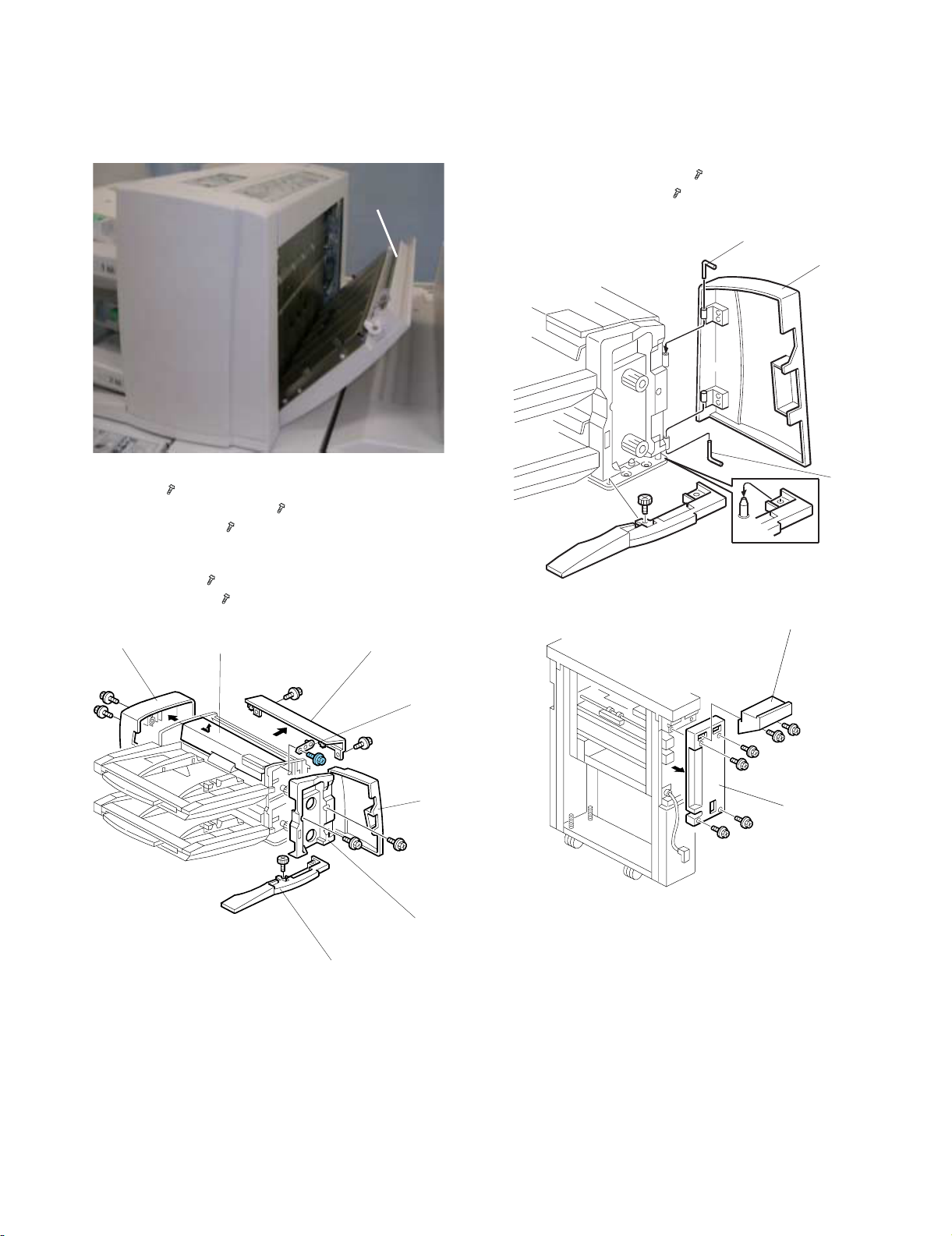
1. COVERS
• Open the vertical feed cover [A].
[A]
Remove:
[A] Top cover ( x2)
[B] Inner cover with front door [C] ( x2)
[D] 1st tray cover holder ( x1)
[E] 1st tray cover. Slide the cover toward you to remove it from the
inside pins.
[F] Base cover (Knob x1)
[G] Tray unit rear cover ( x2)
[G]
[E]
[A]
Remove:
[A] Front door (L-pins x2)
• Swing the upper L-pin [B] out of its groove and pull it up.
• Swing the lower L-pin [C] out of its groove and pull it down.
[D] Rear top cover of the feed unit ( x2)
[E] Feed unit rear upper cover ( x4)
[B]
[A]
[C]
[D]
[F]
[D]
[B]
[C]
[E]
MX-CFX2 REPLACEMENT AND ADJUSTMENT 3 – 1
Page 6
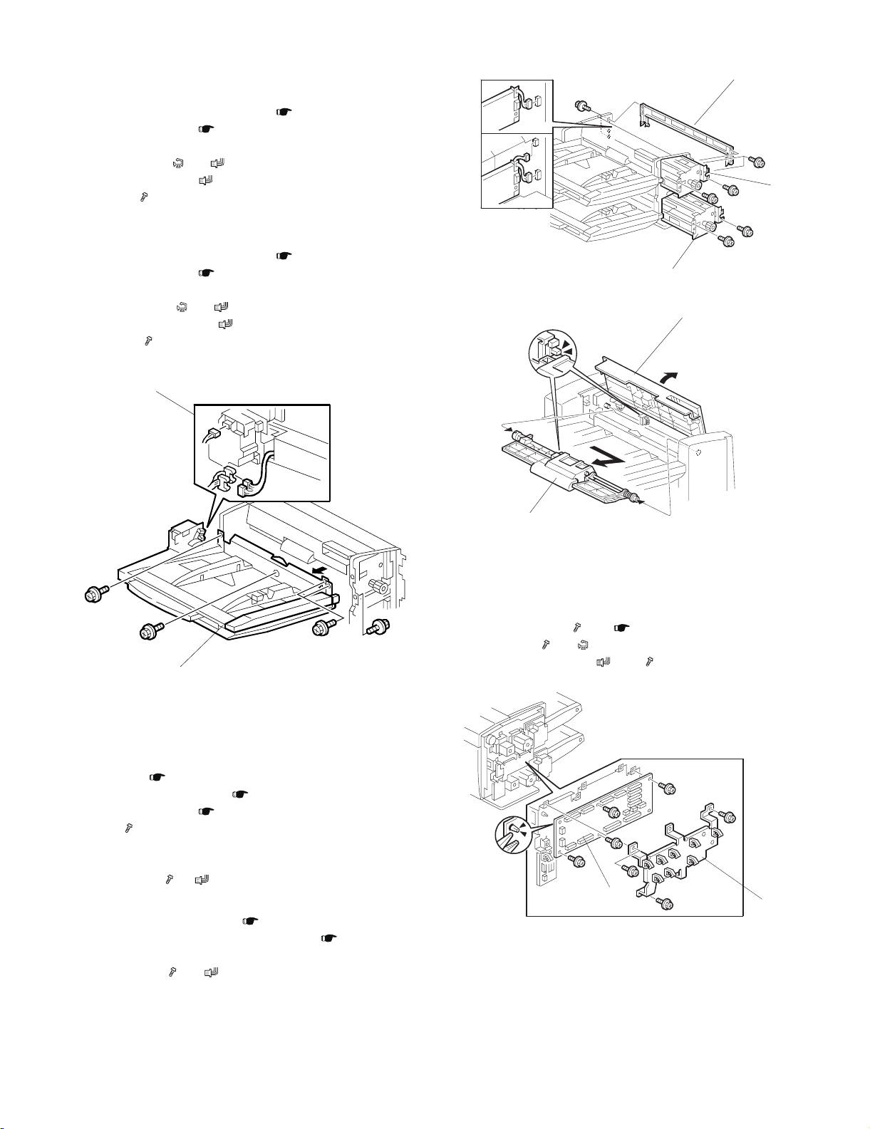
2. 1ST, 2ND TRAYS
[A]
[D]
[E]
1st Tray
2nd Tray
A. 1st Tray
Remove:
• Inner cover with tray unit front door ( 1. COVERS)
• Tray unit rear cover ( 1. COVERS)
[A] Disconnect:
• 1st lift motor ( x1, x1)
• White connectors ( x2)
[B] 1st tray ( x5)
B. 2nd Tray
Remove:
• Inner cover with tray unit front door ( 1. COVERS)
• Tray unit rear cover ( 1. COVERS)
[C] Disconnect:
• 2nd lift motor ( x1, x1)
• Red, blue connectors ( x2)
[D] 2nd tray ( x5)
[A], [C]
[B]
[B], [D]
3. FEED UNITS
A. 1st Feed Unit
Remove:
• Top cover ( 1. COVERS)
• Inner cover with front door ( 1. COVERS)
• Tray unit rear cover ( 1. COVERS)
[A] Stay ( x5)
[B] Open the 1st tray cover and hold it open
[C] 1st feed belt unit
[D] 1st feed unit ( x, x )
B. 2nd Feed Unit
• Open the vertical feed cover ( 1. COVERS)
• Remove inner cover with tray unit front door ( 1. COVERS)
• 2nd feed belt unit (same as [C])
[E] 2nd feed unit ( x2, x2)
[C]
4. BOARDS
A. TRAY UNIT CONTROL BOARD
Remove:
• Tray unit rear cover ( x2) ( 1. COVERS)
[A] Board cover ( x3, x8)
[B] Tray unit control board ( x 17, x5, Standoff x1)
[B]
[A]
MX-CFX2 REPLACEMENT AND ADJUSTMENT 3 – 2
Page 7
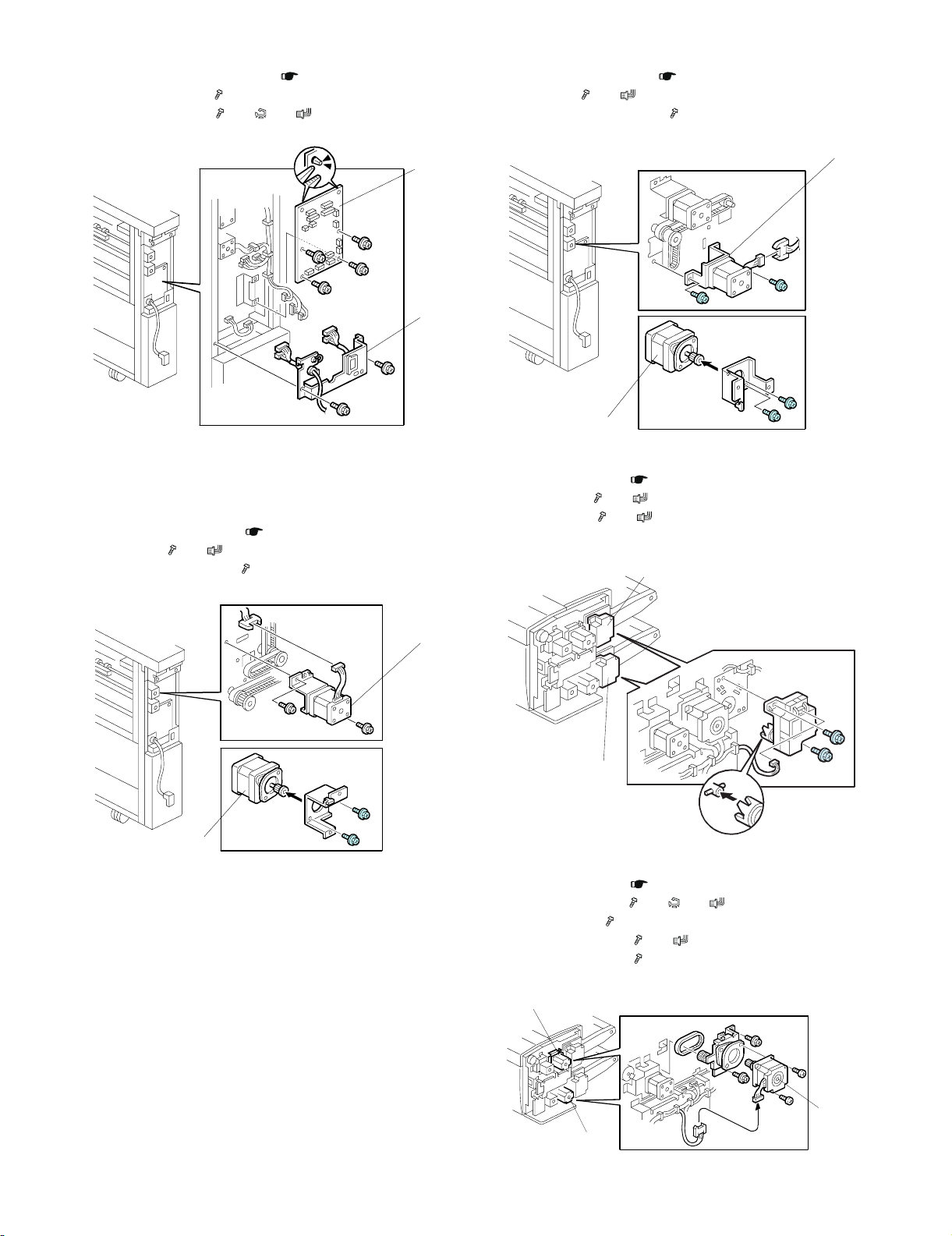
B. MAIN CONTROL BOARD
[A]
[B]
[A]
[B], [D]
[C]
• Transport unit rear upper cover ( 1. COVERS)
[A] Connector bracket ( x2)
[B] Main control board ( x4, x2, x14, Standoff x2)
B. HORIZONTAL TRANSPORT MOTOR
• Transport unit rear cover ( 1. COVERS)
[A] Motor unit ( x2, x1, Timing belt x1)
[B] Horizontal transport motor ( x2)
5. MOTORS
A. VERTICAL TRANSPORT MOTOR
Remove:
• Transport unit rear cover ( 1. COVERS)
[A] Motor unit ( x2, x1, Timing belt x1)
[B] Vertical transport motor ( x2)
[B]
[A]
[A]
[B]
C. 1ST, 2ND LIFT MOTORS
• Tray unit rear cover ( 1. COVERS)
[A] 1st lift motor ( x2, x1)
[B] 2nd lift motor ( x2, x1)
[A]
[B]
D. 1ST, 2ND FEED MOTORS
• Tray unit rear cover ( 1. COVERS)
[A] 1st feed motor unit ( x3, x2, x1)
[B] 1st feed motor ( x2, Timing belt x1)
[C] 2nd feed motor unit ( x3, x1)
[D] 2nd feed motor unit ( x2, Timing belt x1)
MX-CFX2 REPLACEMENT AND ADJUSTMENT 3 – 3
Page 8

E. 1ST, 2ND TRANSPORT MOTORS
[A], [C]
[B], [D]
• Tray unit rear cover ( 1. COVERS)
(1) 1st Transport Motor
[A] 1st transport motor unit ( x3, x1)
[B] 1st transport motor ( x2, Timing belt x1)
(2) 2nd Transport Motor
• (1) Tray unit control board unit (Hooks, x3, x9 (Motor x8,
CN216))
[C] 2nd transport motor unit ( x3)
[D] 2nd transport motor ( x2, Timing belt x1)
[A], [C]
[B], [D]
(1)
(1)
F. 1ST, 2ND PICK-UP MOTORS
• Tray unit rear cover ( 1. COVERS)
(1) 1st Pick-up Motor
[A] 1st pick-up motor unit ( x3, x1)
[B] 1st pick-up motor ( x2, Timing belt x1)
(2) 2nd Pick-up Motor
• (1) Tray unit control board unit (Hooks, x3, x9 (Motor x8,
CN216))
[C] 2nd pick-up motor unit ( x3, x1)
[D] 2nd pick-up motor ( x2, Timing belt x1)
6. SENSORS
A. PAPER WIDTH SWITCH, SET SENSORS,
LENGTH SENSOR
Remove:
• 1st or 2nd paper tray ( 2. 1ST, 2ND TRAYS)
[A] Front cover ( x1)
[B] Rear cover ( x1)
[C] Bottom cover ( x2)
[D] Holder pin ( x1, Spring x1)
[E] Bottom plate ( x1)
• Turn over the bottom plate so it is facing up.
[B]
[A]
MX-CFX2 REPLACEMENT AND ADJUSTMENT 3 – 4
Page 9

[C]
[A]
[B]
Remove:
[A] Harness cover (Hooks x2)
[B] Paper width switch (Hooks x2, x4, x1)
[C] Paper set sensor (Hook x1, x1)
[D] Paper length sensor (Hooks x1, x1)
[A]
[E]
[D]
B. TRAY COVER SENSORS
(1) 1st Tray Cover Sensor
• Remove the tray unit rear cover ( 1. COVERS)
• Open the 1st tray cover
Remove:
[A] Sensor unit ( x1, x1)
[B] Tray cover sensor (Pawls x2)
(2) 2nd Tray Cover Sensor
• Remove the tray unit control board unit ( 5. MOTORS)
Remove:
[A] Sensor unit ( x1, x1). Remove with the 2nd tray cover
open.
[B] Tray cover sensor (Pawls x2)
[B]
[C]
C. 1ST TRANSPORT SENSOR
• Top cover
• Vertical feed cover
• Stay ( 5. MOTORS)
Remove:
[A] Upper paper guide ( x2)
[B] Sensor unit ( x2, x1, x1)
[C] 1st transport sensor (Pawls x2)
[D]
[B]
[A]
[C]
MX-CFX2 REPLACEMENT AND ADJUSTMENT 3 – 5
Page 10

D. FEED UNIT SENSORS
[A]
[B]
[C]
[D]
[E]
[F]
Remove:
[A] 1st feed unit ( 3.FEED UNITS)
[B] 2nd feed unit ( 3.FEED UNITS)
[C] Sensor bracket ( x1, x1)
[D] Pick-up roller HP sensor (Pawls x2)
[E] Sensor bracket ( x1, x1, x1)
[F] Bottom plate position sensor (Pawls x2)
[G] Sensor bracket ( x1, x1) (2nd feed unit only)
[H] 1st Vertical transport sensor (Pawls x2) (2nd feed unit only)
[I] Sensor bracket ( x1, x1, x1)
[J] Paper Feed sensor (Pawls x2)
E. 2ND VERTICAL TRANSPORT, EXIT SENSORS
Remove:
[A] Sensor unit ( x1, x1, x1)
[B] 2nd vertical transport sensor (Pawls x2)
[C] Sensor unit ( x2, x1, x1)
[D] Vertical exit sensor (Pawls x2)
[E] Sensor unit ( x2, x1, x1)
[F] Exit sensor (Pawls x2)
[A]
[B]
[C]
[D]
[E]
[F]
[G]
[H]
[I]
[J]
F. ENTRANCE SENSOR
[A] Sensor unit ( x2, x1, x1)
[B] Entrance sensor (Pawls x2)
[B]
[A]
MX-CFX2 REPLACEMENT AND ADJUSTMENT 3 – 6
Page 11

7. ROLLERS
[A]
[B]
[D]
[E]
A. SEPARATION ROLLER
• 1st (or 2nd) feed unit ( 3.FEED UNITS)
[A] Cover
[B] Separation Roller ( x1)
[A]
[B]
C. FEED BELT
• Feed belt unit ( 7. ROLLERS - B.)
[A] Pick-up roller unit.
• Pull the unit away from the bushings in the direction of the
arrow.
[B] Feed belt holder
• Hold the feed belt holder by the sides, then lift up to separate
from the holder.
• Pull slowly to avoid losing the springs.
[C] Feed belt.
B. FEED BELT UNIT AND PICK-UP ROLLER
• Open the 1st tray cover.
[A] Feed belt unit
• The unit is spring loaded. Push it to the right to release it, then
lift it out.
[B] Pick-up roller ( x 2, bushings x 2)
[A]
[B]
[F]
[C]
Re-assembly
1) Position the pick-up roller unit [A] and feed belt holder [B] as
shown above.
2) On the rear side, slide out the bushing, and rotate guide plate
[D] until its stepped side attaches at [E] as shown above, then
snap the guide plate on.
3) On the front side, rotate guide plate [F] until its flat side is parallel with [D], then snap it on. Viewed from the bottom, the
plates must be aligned.
MX-CFX2 REPLACEMENT AND ADJUSTMENT 3 – 7
Page 12

MX-CFX2
[4] DETAILS
1. PAPER PATH
1
2. PAPER FEED
Service Manual
A. FEED MECHANISM
[C]
2
3
4
[B]
[A]
5
6
8
7
9
10
11
12
13
Interposer Tray
1 1st Paper Feed Motor
2 1st Paper Feed Sensor
3 1st Transport Motor
4 1st Transport Sensor
5 1st Vertical Transport Sensor
6 2nd Paper Feed Motor
7 2nd Paper Feed Sensor
8 2nd Transport Motor
9 2nd Transport Sensor
10 2nd Vertical Transport Sensor
11 Vertical Transport Motor
12 Vertical Exit Sensor
13 Interposer Exit Sensor
14 Interposer Entrance Sensor
15 Horizontal Transport Motor
15
14
Mainframe
[D]
[E]
[F]
[G]
[H]
When paper is placed on the tray, the 1st paper set sensor in the
tray actuates and switches on the 1st tray lift motor. The pick-up
roller unit drops and the top of the stack in the tray pushes up the
pick-up roller unit until its actuator actuates the 1st bottom plate
position sensor [A] and switches the motor 1st tray lift motor off.
The 1st pick-up roller HP sensor [B] controls the operation of the
1st pick-up motor [C]. The 1st pick-up motor is off when the actuator is up and there is no paper in the tray. This is the pick-up roller
home position. When the actuator de-actuates the sensor after the
tray lifts, this switches on the 1st pick-up roller motor. At the end of
the job, the actuator descends with the bottom plate and switches
the motor off.
The pick-up roller [D] picks up the sheet, and the feed belt [E] feeds
the sheet to the paper feed roller [F]. The separation roller [G]
reverses if more than one sheet is fed.
This is a standard FFR device
The paper feed sensor [H] detects the timing of the feed and signals a jam if the paper does not arrive or if the paper stops.
As sheets feed from the top of the stack:
• The pick-up roller unit descends until the actuator on the pick-up
roller unit drops out of the 1st bottom plate position sensor [A].
This activates the 1st tray lift motor.
MX-CFX2 DETAILS 4 – 1
Page 13

• The 1st tray lift motor switches on to raise the stack until the
actuator enters the pick-up roller unit position sensor again and
switches the lift motor off.
• This cycle repeats until the end of the job or until paper runs out.
B. PAPER NEAR END/PAPER END
[C]
[A]
[B]
[D]
When feed starts with a full tray, the actuator [A] on the rotating
shaft of the bottom plate lift arm [B] is at the 1st tray lower limit sensor [C].
As paper feeds and the stack grows smaller, the lift arm rises and
the actuator descends until the actuator reaches the 1st tray upper
limit sensor [D]. At this time the operation panel signals near-end
for the 1st tray.
When the last sheet feeds, the paper feed sensor, a photosensor
(not shown) signals that paper has run out.
C. PAPER SIZE DETECTION
[A]
Paper Size Detection Bits Area
Paper Size W1 W2 W3 W4 W5 L1 NA EU
Large
Size
Large
Size
Large
Size
A3
SEF
A4LEF 297×210 mm H H H L L H YES YES
DLT
SEF
LT LEF 11×8
B4
SEF
B5
LEF
A4
SEF
LT
SEF
A5LEF 210×148 mm H H L H H H * YES
HLT
LEF
B5
SEF
F SEF 8×13 in. H L L H H L YES YES
A5
SEF
HLT
SEF
12×18 in. HHHH L LYESYES
13×19 in. HHHH L L * *
320×450 mmHHHHL L * *
297×420 mm H H H L L L YES YES
11×17 in. H H H L H L YES YES
1
/2 in. H H H L H H YES YES
257×364 mm H H L L H L YES YES
257×182 mm H H L L H H YES YES
210×297 mm H H L H H L YES YES
1
8
/2×11 in. H H L H H L YES *
1
8
/2×5 1/2 in. H H L H H H YES *
182×257 mm H L L H H L * *
148×210 mm H L H H H H YES YES
1
5
/2×8 1/2 in. L L H H H H YES YES
(Yes) Width and length sensors can detect paper sizes automatically.
(*) Accurate paper size detection requires setting with the "Tray
Paper Setting" key on the operation panel.
(H) 5V
(L) 0V
[B]
(1)
[D]
[C]
The side fences (1) and (2) can be adjusted to standard and nonstandard paper sizes.
When the side fences are moved to match the paper width, a feeler
[A] slides along the wiring patterns on the paper width switch terminal plate [B].
The combination of the following two factors determines the paper
size:
• The position where the feeler activates the terminal
• The status of the paper length sensor [C] (ON or OFF).
The paper end sensor [D] de-activates when the last sheet is fed
and reports that the paper tray is empty.
The paper size is detected by six sensors whose combined readings are used to detect the following paper sizes.
(2)
MX-CFX2 DETAILS 4 – 2
Page 14

M2
M4
M3
M7
M8
M5
1
MX-CFX2
[5] OVERALL MACHINE INFROMATION
Service Manual
1. MAIN LAYOUT
M7
M10
M9
3
1 Driver Board
2 Control Board
3 Door Open Switch (Interlock)
M1 1st Lift Motor
M2 1st Paper Feed Motor
M3 1st Pick-up Motor
M4 1st Transport Motor
M5 2nd Paper Feed Motor
M6 2nd Lift Motor
M7 2nd Pick-up Motor
M8 2nd Transport Motor
M9 Horizontal Transport Motor
M10 Vertical Transport Motor
M3
M4
M8
2. DRIVE LAYOUT
1
M2
M1
2
1
M10
M6
M5
M9
2
1 1st Transport roller
2 2nd Transport roller
M9 Horizontal Transport Motor
M10 Vertical Transport Motor
The 1st transport roller [1] (driven by the 1st transport motor) pulls
the paper from the 1st tray and feeds it into the vertical paper path.
The 2nd transport roller [2] (driven by the 2nd transport motor) pulls
the paper from the 2nd tray and feeds it into the vertical path.
The vertical transport motor [3] drives the vertical transport rollers
(1) and (2) that feed the sheets into the horizontal feed path.
The horizontal transport motor [4] drives the horizontal transport
rollers (3) and (4) that feed the covers (and paper passing straight
through) out of the cover interposer tray.
(4)
(2)
(1)
(3)
3. ELECTRICAL COMPONENTS
A. OVERVIEW
(1) FEED MOTORS, PCB
MX-CFX2 OVERALL MACHINE INFROMATION 5 – 1
1 Tray Unit Control Board
M2 1st Paper Feed Motor
M3 1st Pick-Up Motor
M4 1st Transport motor
M5 2nd Paper Feed Motor
M7 2nd Pick-Up Motor
M8 2nd Transport motor
Page 15

(2) LIFT MOTORS, TRAY SENSORS
(4) PAPER PATH SENSORS 2, PCB
M1
S2
S6
S5
M6
S16
S15
M1 1st Lift Motor
M6 2nd Lift Motor
S2 1st Lower Limit Sensor
S3 1st paper set sensor
S5 1st Paper Length Sensor
S6 1st paper upper limit sensor
S11 2nd Lower Limit Sensor
S13 2nd paper set sensor
S15 2nd Paper Length Sensor
S16 2nd paper upper limit sensor
(3) PAPER PATH SENSORS 1
S7
S1
S10
S3
S8
S11
S13
S4
S20
M10
M9
1
1 Main Control Board
M9 Horizontal Transport Motor
M10 Vertical Transport Motor
S20 2nd Vertical Transport Sensor
S21 Entrance Sensor
S22 Exit Sensor
S23 Vertical Exit Sensor
SW1 Feed Unit Front Door Safety Switch
(5) ELECTRICAL COMPONENT SUMMARY
S21
S23
S22
SW1
S12
S17
S19
S14
S1 1st Tray Cover Sensor
S4 1st Paper Feed Sensor
S7 1st Pick-Up Roller HP Sensor
S8 1st Transport Sensor
S9 1st Vertical Transport Sensor
S10 1st bottom plate position sensor
S12 2nd Tray Cover Sensor
S14 2nd Paper Feed Sensor
S17 2nd Pick-Up Roller HP Sensor
S18 2nd Transport Sensor
S19 2nd bottom plate position sensor
SW1 Vertical Feed Cover Switch
S18
SW1
S9
Motors
No. Name Description
M1
TRYLFT1M
M2
FEED1_M
M3
PIKUP1_M
M4
PLOUT1_M
M5
FEED2_M
M6
TRYLFT2M
M7
PIKUP2_M
M8
PLOUT2_M
M9
TRSH_M
M10
TRSV_M
PCBs
No. Name Description
PCB1 Driver Board Controls operation of the unit. (All
PCB2 Main Control Board
1st Lift Motor Drives the bottom plate of the 1st
1st Paper Feed
Motor
1st Pick-up Motor Moves the 1st pick-up roller up and
1st Transport Motor Drives the 1st Transport roller that
2nd Feed Motor Rotates the feed rollers that feed
2nd Lift Motor Drives the bottom plate of the 2nd
2nd Pick-up Motor Moves the 2nd pick-up roller up and
2nd Transport
Motor
Horizontal
Transport Motor
Vertical Transport
Motor
tray up and down.
Rotates the feed rollers that feed
paper from the 1st tray.
down.
takes the paper fed from the 1st feed
roller and feeds it to the vertical path.
paper from the 2nd tray.
tray up and down.
down.
Drives the 2nd Transport roller that
takes the paper fed from the 1st feed
roller and feeds it to the vertical path.
Drives the rollers in the horizontal
path that feed paper from the copier
and covers from the vertical path out
of the cover interposer tray.
Drives the rollers in the vertical path
that feed the covers down to the
horizontal path.
DIP SWs should be set to OFF.)
MX-CFX2 OVERALL MACHINE INFROMATION 5 – 2
Page 16

Sensors
No. Name Description
S1
FECVROP1
S2
LWR LMT1
S3
PPREND1
S4
INSFEED1
S5
PPRLNG1
S6
NEREND1
S7
INSHP1
S8
PLOUT1
S9
VTRS1
S10
UPRLMT1
S11
LWR LMT2
S12
FECVROP2
S13
PPREND2
S14
INSFEED2
S15
PPRLNG2
S16
NEREND2
S17
INSFEED2
S18
PLOUT2
S19
UPRLMT2
S20
VTRS2
S21
INSENT
S22
INSEXT
S23
INSOUT
1st Tray Cover
Sensor
1st Lower Limit
Sensor
1st paper set
sensor
1st Paper Feed
Sensor
1st Paper Length
Sensors
1st paper upper
limit sensor
1st Pick-up Roller
HP Sensor
1st Transport
Sensor
1st Transport
Sensor
1st bottom plate
position sensor
2nd Lower Limit
Sensor
2nd tray cover
sensor
2nd paper set
sensor
2nd Paper Feed
Sensor
2nd Paper Length
Sensor
2nd paper upper
limit sensor
2nd Pick-up Roller
HP Sensor
2nd Transport
Sensor
2nd bottom plate
position sensor
2nd Vertical
Transport Sensor
Entrance Sensor Detects paper jams where paper
Exit Sensor Detects jams where through-paper
Vertical Exit Sensor Detects jams where through-paper
Detects when the 1st tray cover is
open/closed.
Detects 1) whether the 1st tray is
down or not when the tray is not
operating, and 2) detects when the
tray is full when the 1st tray is
operating.
Detects paper end after the last
sheet feeds from the 1st tray.
Detects paper placed on the tray and
starts the 1st lift motor to raise the
bottom plate. This sensor also
detects a jam if the paper stops and
does not leave the 1st tray.
Used in combination with 1st tray
width sensors to determine the size
of paper in the 1st tray.
When an actuator falls into the gap
of this sensor, this signals paper
near end in the 1st tray.
Detects whether the 1st pick-up
roller is up or not.
Detects jams at the point where the
1st Transport roller pulls paper from
the 1st tray.
Detects jams in the path of the 1st
tray.
Detects the top of the paper stack in
the 1st tray when it is at the proper
height for feeding and stops the 1st
lift motor.
Detects 1) whether the 2nd tray is
down or not when the tray is not
operating, and 2) detects when the
tray is full when the 2nd tray is
operating.
Detects when the 2nd tray cover is
open/closed.
Detects paper placed on the tray and
starts the 2nd lift motor to raise the
bottom plate. This sensor also
detects a jam if the paper stops and
does not leave the 2nd tray.
Detects jams when the feed roller
feeds paper from the 2nd tray.
Used in combination with 1st tray
width sensors to determine the size
of paper in the 1st tray.
When an actuator falls into the gap
of this sensor, this signals paper
near end in the 2nd tray.
Detects whether the 2nd pick-up
roller is up or not.
Detects jams at the point where the
2nd Transport roller pulls paper from
the 1st tray.
Detects the top of the paper stack in
the 2nd tray when it is at the proper
height for feeding and stops the 2nd
lift motor.
Detects jams in the vertical path after
a sheet is fed from the 2nd tray.
from the copier enters the unit in the
horizontal feed path.
and covers exit the unit.
and covers exit the vertical feed
path.
Switches
No. Name Description
SW1 Front Door Switch Detects whether the front door is
SW2 Transport Cover
Switch
SW3 1st Paper Width
Switch
SW4 2nd Paper Width
Switch
properly closed. The unit will not
operate when the front door is open.
This is the cover on the right side of
the tray unit. Detects whether the
cover is opened or closed.
Used in combination with the length
sensors to determine the size of
paper in the 1st tray.
Used in combination with the length
sensors to determine the size of
paper in the 2nd tray.
MX-CFX2 OVERALL MACHINE INFROMATION 5 – 3
Page 17

B. BLOCK DIAGRAM
Interlock SW
INSERT FEEDER
5Vdc
24Vdc
24Vdc
SIGNAL
SW2
5Vdc
Pick Up Motor 1
STM1
Inter lock SW
SIGNAL
Feed Motor 1
STM3
SW1
Pull Out Motor 1
STM5
Vertical Transport
Mot or
STM7
Rise Motor 1
M1
Horizont al Transpor t
Pick Up Motor 2
STM2
Mot or
STM8
Feed Motor 2
STM4
Exit Sensor 1 (Sensor 1)
Exit Sensor 2 (Sensor 2)
Entr ance Sensor (Sensor 3)
Ver t ical Trans por t Sensor 2
(Sensor 4)
Pull Out Motor 2
STM6
Rise Motor 2
M2
Paper Lengt h Sensor 1, 2 (Sensor 5, 6)
Paper End Sensor 1, 2 (Sensor 7, 8)
Feed Sensor 1, 2 (Sensor 9, 10)
Home Position Sensor 1, 2 (Sensor 11, 12)
Pull Out Sensor 1, 2 (Sensor 13, 14)
Upper Limit Sensor 1, 2 (Sensor 15, 16)
Lower Limit Sensor 1, 2 (Sensor 17, 18)
Near End Sensor 1,2 (Sensor 19 ,20)
Cover Open Sensor 1, 2 (Sensor 21, 22)
Vert ical Transport Sensor 1 (Sensor 23)
PWB
Control
24Vdc
5Vdc
SIGNAL
D/D
FU100
CP100
Main PWB
MX-CFX2 OVERALL MACHINE INFROMATION 5 – 4
DC POWER LINE
SIGNAL LINE
Page 18

B835 5314A
B835 5315B
CN357
CN358
CN363
CN362
CN361
CN360
CN359
CN356
CN386
CN2 0 5 CN20 5
CN2 0 7 CN20 7
CN2 0 9
CN2 0 9
CN2 0 6 CN20 6
CN200 CN200
54321
CN104
CN1 0 4
CN2 0 8 CN20 8
CN2 1 0
CN2 1 0
CN2 1 1 CN21 1
CN1 0 9 CN1 0 9
CN105
CN1 0 5
CN1 0 6 CN1 0 6
CN1 0 7 CN1 0 7
CN1 0 8
CN201 CN201
CN2 0 2
CN2 0 2
CN2 0 3 CN2 0 3
CN2 0 4
CN1 0 8
CN2 0 4
Main control PWB
C4175110
Motor control PWB
B8355120
CN1 5 4
CN1 5 7
CN1 8 4
CN1 8 7
CN1 5 9 CN1 8 9
CN3 5 0
CN3 5 1
CN3 5 2
CN3 53
CN35 4 CN3 55
CN3 6 4
CN3 6 5
CN3 6 6
B835 5330
B835 5312
B835 5313
B835 5321A
(MOLEX 2.5mm)
(MOLEX 2.5mm)
AW010129
AW010129
CN1 1 3 CN1 1 3
AX040157A
AX040158A
AX040157A
AX040158A
AX060333A
AW010122
AW010122
B8355130A
AX040211A
AX040211A
AX060333A
PMOQFGN
PMOQFGN
CN1 5 6
CN1 8 6
CN1 5 8
CN1 8 8
CN1 5 5
CN1 8 5
CN1 6 3
CN1 9 3
CN258
B835 5323
11
10
987654321
54321
11
10
987654321
123456789
10
11
11
10
987654321
123456789
10
11
123456789
10
11
123
4
12345
12345
1514131211
10
987654321
1514131211
10
987654321
1514131211
10
987654321
123456789
1011121314
15
123456789
1011121314
15
123456789
1011121314
15
1413121110
987654321
1413121110
987654321
1413121110
987654321
123456789
1011121314
123456789
1011121314
123456789
1011121314
123456789
1011121314
15
123456789
1011121314
15
123456789
1011121314
15
1514131211
10
987654321
1514131211
10
987654321
1514131211
10
987654321
321
321
123
321
123
123
Vcc (5V)
No. 2 vertical transport sensor
CGND
12
11
123
12
11
987
123
123
123456789
101112
123456789
101112
65432165432
1
1234567
1234567
8
6543212
1
M
CGND
No. 1 paper size sensor 5
No. 1 paper size sensor 4
No. 1 paper size sensor 3
No. 1 paper size sensor 2
No. 1 paper size sensor 1
Vcc (5V)
No. 1 paper length sensor
CGND
Vcc (5V)
No. 1 paper end sensor
CGND
121110
987654321
121110
987654321
12345
6
12345
6
123
123
123
123
181716151413121110
987654321
123
123
123
123
123
123
181716151413121110
987654321
123
123
123
123
123
123
321
321
123
123
123456789
101112
13
123456789
101112
13
65432165432
1
65432
1
1234567
2
1234567
8
CN3 7 9
CN3 9 3
A
COM(A)
/A
B
COM(B)
/B
M
A
COM(A)
/A
B
COM(B)
/B
M
A
COM(A)
/A
B
COM(B)
/B
M
A
COM(A)
/A
B
COM(B)
/B
M
A
COM(A)
/A
B
COM(B)
/B
M
A
COM(A)
/A
B
COM(B)
/B
M
123
4
B835 5311
B835 5320A
B835 5324A
CN288
CN268
CN298
12345
6
65432
1
CN267 CN297
123456789
101112
121110
987654321
123456789
101112
121110
987654321
B835 5322A
Yellow
Brown
AW010107
AW010122
AW020160
AW020160
AW020160
AW020160
AW020160
B835 5331
Inserter
PGND [0]
PGND [0]
N.C
Vaa(24V) [24]
Vaa(24V) [24]
No. 1 paper feed M_CLK [0/5]
No. 1 paper feed M_EN [0/5]
No. 1 paper feed M_CWB [0/5]
No. 1 pull-out M_EN [0/5]
No. 1 pull-out M_CLK [0/5]
No. 1 pull-out M_CWB [0/5]
No. 1 pick-up M_CLK [0/5]
No. 1 pick-up M_EN [0/5]
No.1liftM(-)[0/5]
No. 1 lift M(+) [0/5]
(Upper cover open detection) [0/5]
No. 2 paper feed M_CLK [0/5]
No. 2 paper feed M_EN [0/5]
No. 1 paper feed M_CWB [0/5]
No. 2 pull-out M_EN [0/5]
No. 2 pull-out M_CLK [0/5]
No. 2 pull-out M_CWB [0/5]
No. 2 pick-up M_CLK [0/5]
No. 2 pick-up M_EN [0/5]
No. 2 lift M(-) [0/5]
No. 2 lift M(+) [0/5]
Vertical transport cover open/close SW [0/5]
CGND [0]
CGND [0]
Vcc (5V) [5]
Vcc (5V) [5]
No. 1 paper feed cover sensor
No. 1 paper size sensor 5
No. 1 paper size sensor 4
No. 1 paper size sensor 3
No. 1 paper size sensor 2
No. 1 paper size sensor 1
No. 1 paper length sensor
No. 1 paper end sensor
No. 1 HP sensor
No. 1 near end sensor
No. 1 lower limit sensor
No. 1 upper limit sensor
No. 1 pull-out sensor
No. 1 paper feed sensor
No. 2 paper feed cover sensor
No. 2 paper size sensor 5
No. 2 paper size sensor 4
No. 2 paper size sensor 3
No. 2 paper size sensor 2
No. 2 paper size sensor 1
No. 2 paper length sensor
No. 2 paper end sensor
No. 2 HP sensor
No. 2 near end sensor
No. 2 lower limit sensor
No. 2 upper limit sensor
No. 2 pull-out sensor
No. 2 paper feed sensor
No. 1 vertical transport sensor
Vcc (5V)
Paper exit sensor
CGND
Paper exit sensor
No. 2 vertical
transport sensor
PGND [0]
PGND [0]
N.C
Vaa(24V) [24]
Vaa(24V) [24]
No. 1 paper feed M A [0/24]
No. 1 paper feed M COM [24]
No. 1 paper feed M /A [0/24]
No. 1 paper feed M B [0/24]
No. 1 paper feed M COM [24]
No. 1 paper feed M /B [0/24]
No. 1 pull-out M A [0/24]
No. 1 pull-out M COM [24]
No. 1 pull-out M /A [0/24]
No. 1 pull-out M B [0/24]
No. 1 pull-out M COM [24]
No. 1 pull-out M /B [0/24]
No. 1 paper feed M_CLK [0/5]
No. 1 paper feed M_EN [0/5]
No. 1 paper feed M_CWB [0/5]
No. 1 pull-out M_EN [0/5]
No. 1 pull-out M_CLK [0/5]
No. 1 pull-out M_CWB [0/5]
No. 1 pick-up M_CLK [0/5]
No. 1 pick-up M_EN [0/5]
No. 1 lift M(-) [0/5]
No. 1 lift M(+) [0/5]
(Upper cover open detection) [0/5]
No. 1 pick-up M A [0/24]
No. 1 pick-up M COM [24]
No. 1 pick-up M /A [0/24]
No. 1 pick-up M B [0/24]
No. 1 pick-up M COM [24]
No. 1 pick-up M /B [0/24]
No. 1 lift M_OUT(-) [0/24]
No. 1 lift M_OUT(+) [0/24]
No. 1 paper feed
motor
No. 1 pull-out
motor
No. 1 pick-up
motor
No. 1 lift motor
No. 2 paper feed M_CLK [0/5]
No. 2 paper feed M_EN [0/5]
No. 1 paper feed M_CWB [0/5]
No. 2 pull-out M_EN [0/5]
No. 2 pull-out M_CLK [0/5]
No. 2 pull-out M_CWB [0/5]
No. 2 pick-up M_CLK [0/5]
No. 2 pick-up M_EN [0/5]
No. 2 lift M(-) [0/5]
No. 2 lift M(+) [0/5]
Vertical transport cover open/close SW
[0/5]
CGND [0]
CGND [0]
Vcc (5V) [5]
Vcc (5V) [5]
(CT)
(MiniMiII)
(CT)
(CT)
(CT)
(CT)
No. 1 paper size sensor
No. 1 paper length
sensor
No. 1 paper end
sensor
No. 1 paper feed sensor
No. 1
paper feed cover sensor
No. 1 paper size sensor 5
No. 1 paper size sensor 4
No. 1 paper size sensor 3
No. 1 paper size sensor 2
No. 1 paper size sensor 1
No. 1 paper length sensor
No. 1 paper end sensor
No. 1 HP sensor
No. 1 near end sensor
No. 1 lower limit sensor
No. 1 upper limit sensor
No. 1 pull-out sensor
No. 1 paper feed sensor
Vcc (5V) [5]
No. 1 paper feed sensor
CGND [0]
Vcc (5V) [5]
No. 1 pull-out sensor
CGND [0]
Vcc (5V) [5]
No. 1 HP sensor
CGND [0]
Vcc (5V) [5]
No. 1 upper limit sensor
CGND [0]
Vcc (5V) [5]
No. 1 lower limit sensor
CGND [0]
Vcc (5V) [5]
No. 1 near end sensor
CGND [0]
No. 1 pull-out sensor
No. 1 HP sensor
No. 1 upper limit sensor
No. 1 lower limit sensor
No. 1 near end sensor
No. 2
paper feed cover sensor
No. 2 paper size sensor 5
No. 2 paper size sensor 4
No. 2 paper size sensor 3
No. 2 paper size sensor 2
No. 2 paper size sensor 1
No. 2 paper length sensor
No. 2 paper end sensor
No. 2 HP sensor
No. 2 near end sensor
No. 2 lower limit sensor
No. 2 upper limit sensor
No. 2 pull-out sensor
No. 2 paper feed sensor
No. 1 vertical transport sensor
Vcc (5V) [5]
No. 1 paper feed cover sensor
CGND [0]
No. 2 paper feed M A [0/24]
No. 2 paper feed M COM [24]
No. 2 paper feed M /A [0/24]
No. 2 paper feed M B [0/24]
No. 2 paper feed M COM [24]
No. 2 paper feed M /B [0/24]
No. 2 pull-out M A [0/24]
No. 2 pull-out M COM [24]
No. 2 pull-out M /A [0/24]
No.2 pull-out M B [0/24]
No. 2 pull-out M COM [24]
No. 2 pull-out M /B [0/24]
NC
No. 2 pick-up M A [0/24]
No. 2 pick-up M COM [24]
No. 2 pick-up M /A [0/24]
No. 2 pick-up M B [0/24]
No. 2 pick-up M COM [24]
No. 2 pick-up M /B [0/24]
No 2 lift M OUT(-) [0/24]
No. 1 paper feed
cover sensor
No. 2 paper feed motor
No. 2 pull-out motor
No. 2 pick-up motor
C. ACTUAL WIRING CHART
MX-CFX2 OVERALL MACHINE INFROMATION 5 – 5
Page 19

4
3
4
B
No
2pick
up M B [0/24]
sensor
B835 5325A
CN29 5
CN2 6 5
AW010122
CN388
123
123
321
123
No. 2 vertical transport
AW010107
AW010122
AW020160
AW020160
AW020160
AX040211A
No.2liftmotor
B8355130A
No. 2 paper size sensor
AW010129
No. 2 paper length sensor
AW010129
No. 2 paper end sensor
No. 2 paper feed sensor
No. 2 pull-out sensor
No. 2 HP sensor
No. 2 upper limit sensor
No. 2 lower limit sensor
AW020160
No. 2 near end sensor
AW020160
No. 2 paper feed cover sensor
M
CN371
CN370
6
123
123
123
123
6
(CT)
987654321
101112
2
1
CN3 6 9
12345
12345
CN3 6 8
CN3 6 7
(CT)
B835 5322 A
121110
CN299
(CT)
123456789
CN269
/B
COM(B)
2
1
(CT)
CN372
123
123
B835 5323A
121110
CN3 0 0
123456789
CN2 6 3
CN374
CN373
123
123
123
123
987654321
123
123
101112
CN375
CN376
123
123
65432
12345
123
123
CN377
1
CN387
123
123
CN301
6
CN270
(Not installed)
1
2
1
2
12042529
open/close SW
Vertical transport cover
High active
SYMBOL TABLE
Low active
[ ] Voltage
Pulse
Signal flow
AC LINE
DC LINE
B835 5327
Vaa.SW(N.O)
Vaa(COM)
••• •••
132
123
• • SW(N.C)
CN3 9 0
123
123
CN3 8 9
CN266 CN296
B835 5326
56789
56789
-
.
No. 2 pick-up M /B [0/24]
No. 2 lift M_OUT(-) [0/24]
No. 2 pick-up M COM [24]
AW010122
No. 2 vertical
transport sensor
CN3 7 9
123
123
B835 5315B
987654321
123456789
CN1 5 9 CN1 8 9
121110
121110
CN1 0 9 CN1 0 9
Vcc (5V)
No. 2 vertical transport sensor
131211
131211
CN2 1 2 CN21 2
NC
(CT)
CGND
No. 2 lift M_OUT(+) [0/24]
No. 2 paper size sensor 5
AW010122
(Not installed)
Exit port sensor
CN3 8 1
CN3 8 0
123
123
123
123
987654321
987654321
CGND
CGND
CGND
Vcc (5V)
Vcc (5V)
Exit port sensor
(Vertical transport sensor)
987654321
10
987654321
10
Vcc (5V)
No. 2 paper size sensor 4
No. 2 paper size sensor 3
No. 2 paper size sensor 2
No. 2 paper size sensor 1
AW010122
Inlet port sensor
CN3 8 2
123
123
B835 5316A
321
123
CGND
Vcc (5V)
Inletportsensor
CN1 9 0
CN1 6 0
No. 2 paper length sensor
CGND
Vcc
CGND
No. 2 paper end sensor
A
CN3 8 3
CN1 1 0
CN110
CN2 1 3 CN2 1 3
NC
(Mini Mi II)
AX040158A
Vertical transport motor
M
/A
COM(A)
65432
12345
12345
Vertical transport M A [0/24]
Vertical transport M /A [0/24]
Vertical transport M COM [24]
B
Vertical transport M B [0/24]
191817161514131211
191817161514131211
CGND [0]
CGND [0]
Vcc (5V) [5]
Vcc (5V) [5]
Vcc (5V) [5]
No. 2 pull-out sensor
No. 2 paper feed sensor
AX040158 A
Horizontal transport motor
A
/A
/B
COM(A)
COM(B)
1
65432
CN3 8 4
6
1234567
6
1234567
CN1 1 1 CN1 1 1
Vertical transport M /B [0/24]
Vertical transport M COM [24]
Horizontal transport M A [0/24]
Horizontal transport M /A [0/24]
Horizontal transport M COM [24]
CGND [0]
No. 2 HP sensor
M
B
Horizontal transport M B [0/24]
COM(B)
Horizontal transport M COM [24]
/B
1
Horizontal transport M /B [0/24]
987654321
10
987654321
10
CGND [0]
CGND [0]
Vcc (5V) [5]
Vcc (5V) [5]
Vcc (5V) [5]
No. 2 lower limit sensor
No. 2 upper limit sensor
123
123
CN1 9 1
123
CN1 6 1
123
CN1 1 2
123
CN112
NC
Vaa (COM) [24]
No. 2 near end sensor
12042382
Front door SW [0/5]
432
1
54321
432
1
CN2 1 4 CN2 1 4
NC
CGND [0]
CGND [0]
Vcc (5V) [5]
54321
CN2 1 5 CN21 5
NC
CGND [0]
Vcc (5V) [5]
123
4
(MOLEX 2.5mm)
123
4
CN2 1 6 CN21 6
NC
CGND [0]
Vaa (COM) [24]
Vaa. SW (N. C) [0/24]
No. 2 paper feed cover sensor
(Upper cover open/close detection)
No. 2 vertical transport sensor
Vertical transport cover open/close SW (N.C) [0/24]
Main unit
CN301
Front door SW
C417 5300A
123456789
123456789
CN1 0 0 CN1 0 0
N. C
Vaa (24V) [24]
Vaa (24V) [24]
Vaa (24V) [24]
N. C
Vaa (24V) [24]
Vaa (24V) [24]
Vaa (24V) [24]
987654321
CN1 0 2
F. G
1234567
CN1 0 1
1234567
CN1 0 1
Vaa (24V) [24]
GND1 (PGND) [0]
GND1 (PGND) [0]
Vaa (24V) [24]
GND1 (PGND) [0]
GND1 (PGND) [0]
GND2 [0]
GND1 (PGND) [0]
GND1 (PGND) [0]
GND2 [0]
GND1 (PGND) [0]
GND2 [0]
GND1 (PGND) [0]
8765432
8765432
CN1 0 3 CN10 3
8
8
+5V [5]
+5V [5]
5VE [0/5]
GND2 [0]
TXD0(RXD) [0/5]
RXD0(TXD) [0/5]
ZESM signal [0/5]
+5V [5]
+5V [5]
TXD1 [0/5]
ZESM signal [0/5]
RXD1 [0/5]
5VE [0/5]
1
1
CGND [0]
4
4
4
4
4
Vaa. SW (N. O) [0/240
B835 5318
B835 5317A
CN5 0 0
12345
--
MD2 [0/5]
FWE [0/5]
MD1 [0/5]
123
4
CN5 0 1
CGND [0]
TXD2 [0/5]
RXD2 [0/5]
RESET [0/5]
Vcc (5V) [5]
MX-CFX2 OVERALL MACHINE INFROMATION 5 – 6
1234567
CN4 0 2
8
After-process unit
Page 20

y
LEAD-FREE SOLDER
The PWB’s of this model employs lead-free solder. The “LF” marks indicated on the PWB’s and the Service Manual mean “Lead-Free” solder.
The alphabet following the LF mark shows the kind of lead-free solder.
Example:
<Solder composition code of lead-free solder>
Solder composition
Sn-Ag-Cu
Sn-Ag-Bi
Sn-Ag-Bi-Cu
Sn-Zn-Bi
Sn-In-Ag-Bi
Sn-Cu-Ni
Sn-Ag-Sb
Bi-Sn-Ag-P
Bi-Sn-Ag
5mm
Lead-Free
Solder composition
code (Refer to the
table at the right.)
a
(1) NOTE FOR THE USE OF LEAD-FREE SOLDER THREAD
When repairing a lead-free solder PWB, use lead-free solder thread.
Never use conventional lead solder thread, which may cause a breakdown or an accident.
Since the melting point of lead-free solder thread is about 40°C higher than that of conventional lead solder thread, the use of the
exclusive-use soldering iron is recommended.
Solder composition code
a
b
z
i
n
s
p
(2) NOTE FOR SOLDERING WORK
Since the melting point of lead-free solder is about 220°C, which is about 40°C higher than that of conventional lead solder, and its soldering
capacity is inferior to conventional one, it is apt to keep the soldering iron in contact with the PWB for longer time. This may cause land
separation or may exceed the heat-resistive temperature of components. Use enough care to separate the soldering iron from the PWB when
completion of soldering is confirmed.
Since lead-free solder includes a greater quantity of tin, the iron tip may corrode easily. Turn ON/OFF the soldering iron power frequently.
If different-kind solder remains on the soldering iron tip, it is melted together with lead-free solder. To avoid this, clean the soldering iron
tip after completion of soldering work.
If the soldering iron tip is discolored black during soldering work, clean and file the tip with steel wool or a fine file.
COPYRIGHT©XXXX BYSHARP CORPORATION
COPYRIGHT©XXXX BYSHARP CORPORATION
ALL RIGHTS RESERVED.
ALL RIGHTS RESERVED.
No part of this publication may be reproduced,
No part of this publication may be reproduced,
stored in a retrieval system, or transmitted in
stored in a retrieval system, or transmitted in
any form or by any means, electronic, mechanical,
form or byanymeans, electronic, mechanical,
an
photocopying, recording, or otherwise, without
prior written permission of the publisher.
Page 21

CAUTION FOR BATTERY REPLACEMENT
(Danish) ADVARSEL !
Lithiumbatteri – Eksplosionsfare ved fejlagtig håndtering.
(English) Caution !
Danger of explosion if battery is incorrectly replaced.
Dispose of used batteries according to manufacturer’s instructions.
(Finnish) VAROITUS
Paristo voi räjähtää, jos se on virheellisesti asennettu.
Vaihda paristo ainoastaan laitevalmistajan suosittelemaan
(French) ATTENTION
Il y a danger d’explosion s’ il y a remplacement incorrect
de la batterie. Remplacer uniquement avec une batterie du
même type ou d’un type équivalent recommandé par
Mettre au rebut les batteries usagées conformément aux
(Swedish) VARNING
(German) Achtung
Explosionsgefahr bei Verwendung inkorrekter Batterien.
Als Ersatzbatterien dürfen nur Batterien vom gleichen Typ oder
vom Hersteller empfohlene Batterien verwendet werden.
Entsorgung der gebrauchten Batterien nur nach den vom
Udskiftning må kun ske med batteri
af samme fabrikat og type.
Levér det brugte batteri tilbage til leverandoren.
Replace only with the same or equivalent type
recommended by the manufacturer.
tyyppiin. Hävitä käytetty paristo valmistajan ohjeiden
mukaisesti.
le constructeur.
instructions du fabricant.
Explosionsfara vid felaktigt batteribyte.
Använd samma batterityp eller en ekvivalent
typ som rekommenderas av apparattillverkaren.
Kassera använt batteri enligt fabrikantens
instruktion.
Hersteller angegebenen Anweisungen.
CAUTION FOR BATTERY DISPOSAL
(For USA, CANADA)
THIS PRODUCT CONTAINS A LITHIUM PRIMARY
(MANGANESS DIOXIDE) MEMORY BACK-UP BATTERY
THAT MUST BE DISPOSED OF PROPERLY. REMOVE THE
BATTERY FROM THE PRODUCT AND CONTACT YOUR
LOCAL ENVIRONMENTAL AGENCIES FOR INFORMATION
ON RECYCLING AND DISPOSAL OPTIONS.
CE PRODUIT CONTIENT UNE PILE DE SAUVEGARDE DE
MÉMOIRE LITHIUM PRIMAIRE (DIOXYDE DE MANGANÈSE)
QUI DOIT ÊTRE TRAITÉE CORRECTEMENT. ENLEVEZ LA
PILE DU PRODUIT ET PRENEZ CONTACT AVEC VOTRE
AGENCE ENVIRONNEMENTALE LOCALE POUR DES
INFORMATIONS SUR LES MÉTHODES DE RECYCLAGE ET
“BATTERY DISPOSAL”
“TRAITEMENT DES PILES USAGÉES”
DE TRAITEMENT.
Page 22

COPYRIGHT 2007 BY SHARP CORPORATION
All rights reserved.
Printed in Japan.
No part of this publication may be reproduced,
stored in a retrieval system, or transmitted,
in any form or by any means,
electronic; mechanical; photocopying; recording or otherwise
without prior written permission of the publisher.
Trademark acknowledgements
Microsoft
Corporation in the U. S.A. and other countries.
Windows
Windows®
and
U.S.A. and other countries.
IBM and PC/AT are trademarks of International Business Machines Corporation.
Acrobat
reserved. Adobe, the Adobe logo, Acrobat, and the Acrobat logo are trademarks
of Adobe Systems Incorporated.
All other trademarks and copyrights are the property of their respective owners.
®
Windows® operating system is a trademark or copyright of Microsoft
®
95, Windows®
XP, Windows®
Internet Explorer®
®
Reader Copyright® 1987-2002 Adobe Systems Incorporated. All rights
98, Windows® Me, Windows NT®
Vista, Windows®
2000 Server, Windows®
4.0, Windows® 2000,
are trademarks or copyrights of Microsoft Corporation
Server 2003
in the
SHARP CORPORATION
Digital Document System Group
CS Promotion Center
Yamatokoriyama, Nara 639-1186, Japan
2007 May Printed in Japan
 Loading...