

Page 1
Sharp LC-60LE644U Service manual
LED COLOR TELEVISION
SERVICE MANUAL
LC-60LE644U
60” FHD 120HZ LED TV
.
1
Page 2

Sharp LC-60LE644U Service manual
Contents
IMPORTANT SERVICE SAFETY PRECAUTION……………………………………………………..3
1. Function Diagram………………………………………………………………………………………..4
2. System block……………………………………………………………………………………………..5
3. Disassembly method
3.1 Disassembly stand unit and Rear cabinet Ass’y……………………………………………......6
3.2 Disassembly the metal parts and attached Ass’y……………………………………………….7
3.3 Disassembly the board Ass’y…………………………………………………………………......8
3.4 Harness picture……………………………………………………………………………………..9
3.5 Tearing off the LVDS cable with silicon………………………………………………………….9
4. Basic schematic of port
4.1 Power circuit……………………………………………………………………………………….10
4.2 Reset circuit………………………………………………………………………………………..14
4.3 IR&KEY circuit……………………………………………………………………………………..15
4.4 VGA INPUT………………………………………………………………………………………...16
4.5 SPDIF OUTPUT…………………………………………………………………………………...17
4.6 AV& YPBPR……………………………………………………………………………………….18
4.7 HDMI Circuit……………………………………………………………………………………….19
4.8 USB Circuit………………………………………………………………………………………...21
4.9 AMP Circuit………………………………………………………………………………………...21
4.10 Main controller MSD3393LU…………………………………………………………………...23
4.11 WIFI Circuit……………………………………………………………………………………….24
5. Trouble shooting table
5.1 Power Troubleshooting…………………………………………………………………………...25
5.2 Display Troubleshooting………………………………………………………………………….26
5.3 Audio Troubleshooting…………………………………………………………………………….28
5.4 Function Troubleshooting………………………………………………………………………...29
6. Software update procedure
6.1 Enter factory menu mode method……………………………………………………………….35
6.2 Software update procedure………………………………………………………………………36
7. Connector define………………………………………………………………………………………..38
8. Critical components list
8.1 Critical components list for Main Board…………………………………………………………42
8.2 Critical components list for Power Board……………………………………………………….43
9. Mechanical Explosion Diagram
9.1 TV Set Explosion Diagram………………………………………………………………………..46
9.2 Packing Explosion Diagram………………………………………………………………………48
10. SUPPLIED ACCESSORIES………………………………………………………………………….50
2
Page 3
Sharp LC-60LE644U Service manual
IMPORTANT SERVICE SAFETY PRECAUTION
Service work shoud be performed only by qualified service technicians who are thoroughly familiar with
all safety checks and the servicing guidelines which are as follows:
WARNING
1..For continued safety,no modification of any circuit earth ground,such as electrical or electrical
..should be attempted. around connected to an earth ground.
2..Disconnect AC power before servicing. • Use an AC voltmeter having with 5000 ohm per volt,
or higher,sensitivity or measure the AC voltage drop
across the resistor.
• Connect the resistor connection to all exposed metal
parts having a return to the chassis (antenna, metal
cabinet, screw heads, knobs and control shafts,
escutcheon, etc.) and measure the AC voltage drop
T5.0AH (5.0A,250V)
BEFORE RETURNING THE RECEIVER
(Fire & Shock Hazard) a potential shock hazard which must be corrected
Before returning the receiver,the user should perform
the following safety checks:
1. Inspect all lead dress to make certain that leads are
not pinched,and check that hardware is not lodged
between the chassis and other metal parts in the
receiver.
2. Inspect all protective devices such as non-metallic
control knobs,insulation materials,cabinet backs,
adjustment and compartment covers or shields,
isolation resistor-capacitor networks,mechanical
insulators,etc.
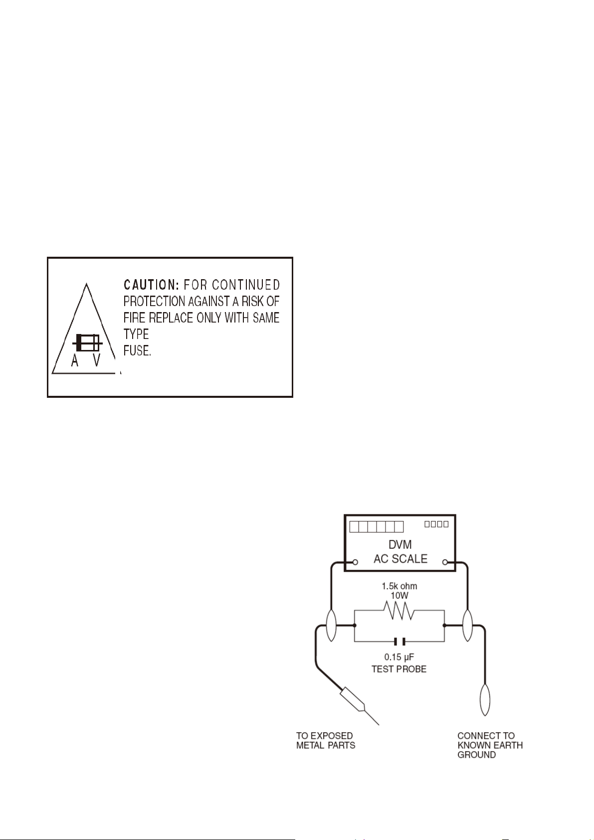
3. To be sure that no shock hazard exists,check for
leakage current in the following manner.
· Plug the AC cord directly into a 200 volt AC outlet,
and connect the DC power cable into the receiver’s
DC jack.(Do not use an isolation transformer for this
test) .
· Using two clip leads,connect a 1.5K ohm,10 watt
1
across the resistor.
All checks must be repeated with the AC cord plug
connection reversed. (If necessary, a nonpolarized
adaptor plug must be used only for the purpose of
completing these checks.)
Any reading of 0.75V peak (this corresponds to 0.5
mA. peak AC.) or more is excessive and indicates
before returning the monitor to the owner.
3
Page 4
Sharp LC-60LE644U Service manual
resistor paralleled by a 0.15uF capacitor in series
with all exposed metal cabinet parts and a known
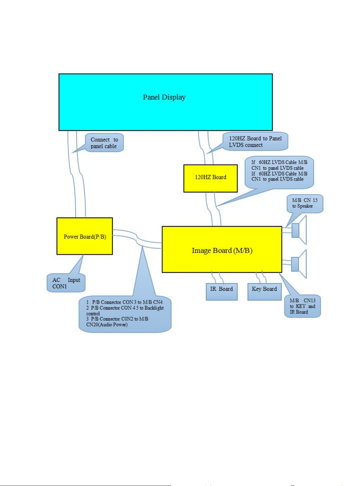
1.Function Diagram
1 Function of Board:
1) Image Board(M/B):Control all input signals, Decode the video signal, De-interlace, and send
digital signal (LVDS signal) sent from image Board and display;
2) Panel:Display all image;
3) Key Pad Board: POWER、SOURCE、MENU、Channel -/+、VOL-/+;
4) IR Board :Receive IR Signal; LED R/G
5) Inverter and Power: the Power Supply for Panel, Image Board;
4
Page 5
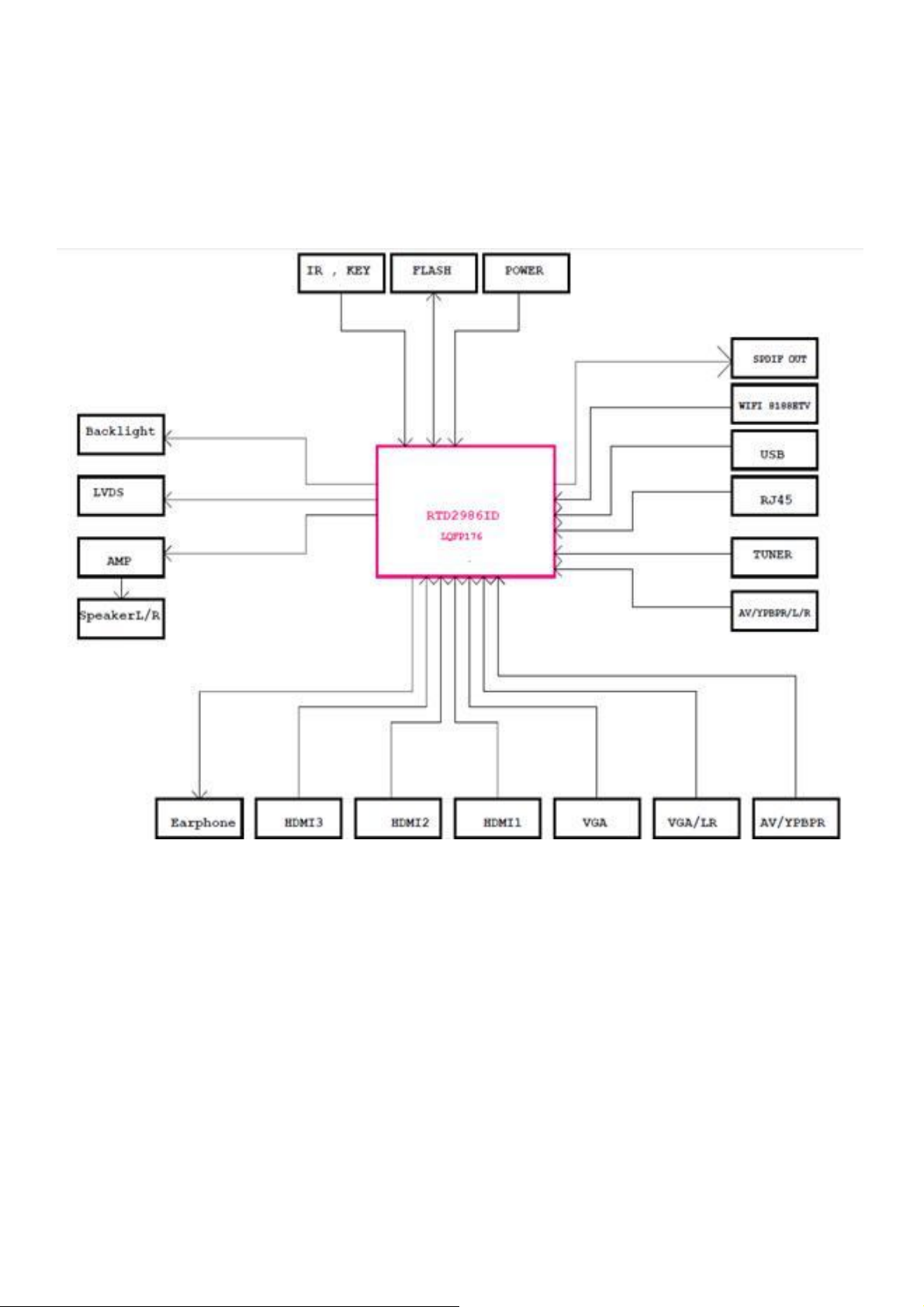
2、System block
Sharp LC-60LE644U Service manual
5
Page 6
Sharp LC-60LE644U Service manual
3. Disassembly the TV set method
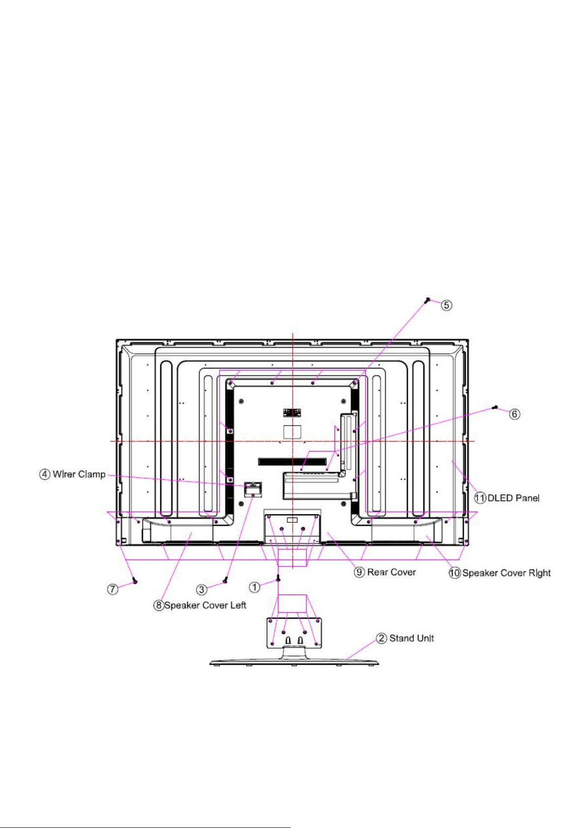
3.1 Disassembly stand unit and Rear cabinet Ass’y.
Removing the Stand Unit, the Wirer Clamp and the Speaker Cover Left and the Rear
Cabinet and the Speaker Cover right.
Step 1 Remove 6 pcs lock screws ① and detach the Stand Unit ②
Step 2 Remove 1 pcs lock screws ③ , 16 pcs lock screw ⑤, 4 pcs lock screws ⑥ ,
8 pcs lock screws ⑦ and detach the Wirer Clamp ④ and the Speaker Cover Left ⑧
and the Rear Cabinet ⑨ and the Speaker Cover right ⑩.
The detail screws sign as following picture3.1
Picture 3.1
6
Page 7
Sharp LC-60LE644U Service manual
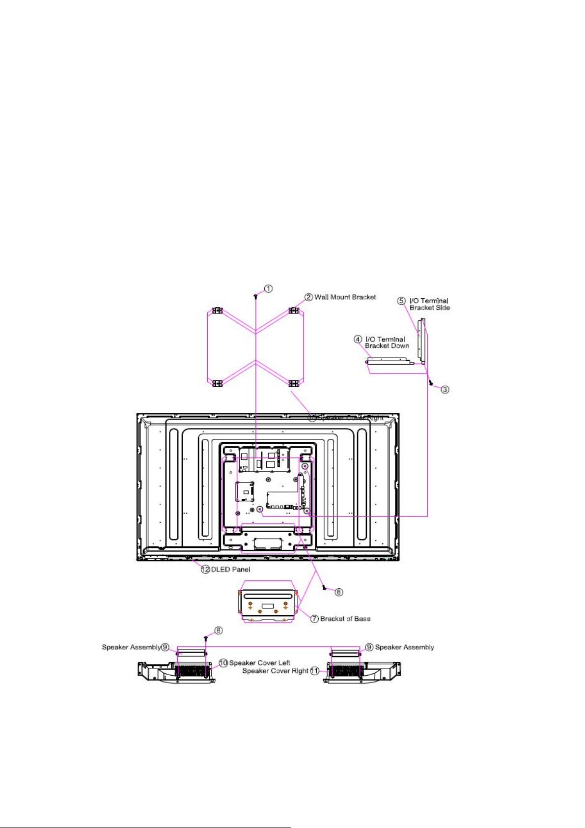
3.2 Disassembly the metal parts and attached Ass’y.
Removing the Wall Mount Bracket, I/O Terminal Bracket Down/Side, the bracket of base,
and Speaker.
Step 1 Remove 16 pcs lock screws ① and detach the Wall Mount Bracket ②.
Step 2 Remove 3 pcs lock screws ③ and detach the I/O Terminal Bracket Down/Side ④/⑤.
Step 3 Remove 4 pcs lock screws ⑥ and detach the bracket of base ⑦.
Step 4 Remove 4 pcs lock screws ⑧and detach the Speaker assembly ⑨ from the Speaker
Cover left / right ⑩/
11
○
.
The detail screws and parts sign as following picture3.2
Picture 3.2
7
Page 8
Sharp LC-60LE644U Service manual
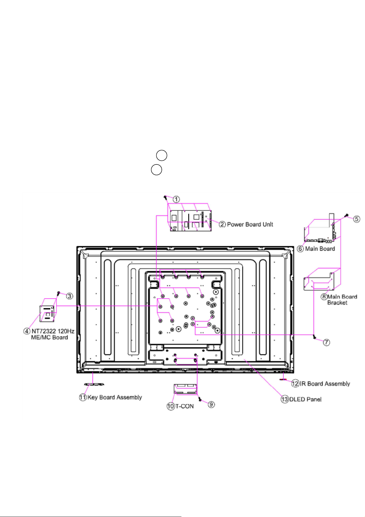
3.3 Disassembly the board Ass’y.
Removing t the Power Board Unit, the NT72322 120Hz ME/MC Board, the Main Board,
the Main Board Bracket, the T-CON Board, the Key board and the IR board.
Step 1 Remove 8 pcs lock screws ① and detach the Power Board Unit ②.
Step 2 Remove 4 pcs lock screws ③ and detach the NT72322 120Hz ME/MC Board ④.
Step 3 Remove 4 pcs lock screws ⑤ and detach the Main Board ⑥.
Step 4 Remove 4 pcs lock screws ⑦ and detach the Main Board Bracket ⑧
Step 5 Remove 2 pcs lock screws ⑨ and detach the T-CON Board ⑩.
Step 6 Detach the Key Board Assembly 11 .
Step 7 Detach the IR Board Assembly 12 .
The detail screws and parts sign as following picture3.3
3.4 Harness picture
Picture 3.3
8
Page 9
Sharp LC-60LE644U Service manual
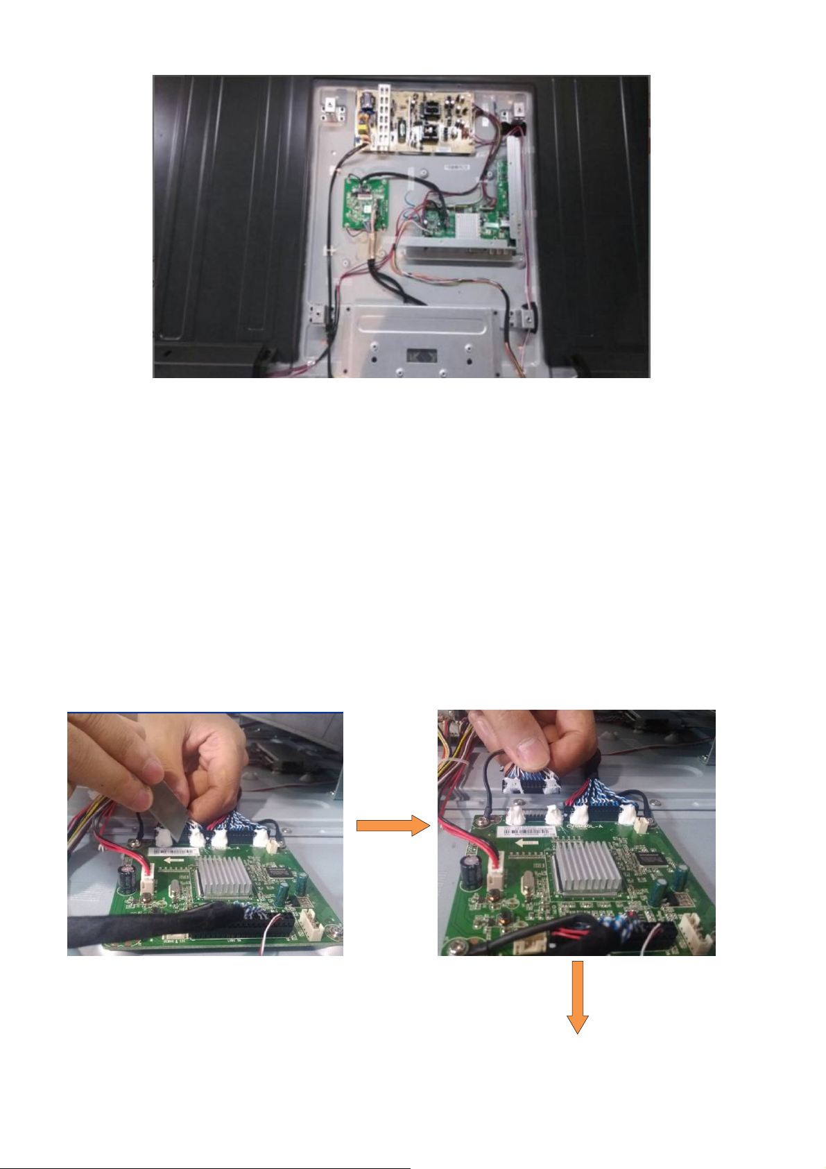
3.5 Tearing off the LVDS cable with silicon
Step 1 Put the art knife aside the LVDS’s connector, and cut the silicon apart. As photo 3.4.
Note:Don’t damage the main board and cable when cut the silicon apart with art knife.
Step 2 Pull the LVDS cable from the main board, as photo 3.5.
Note:To avoid the damage of the pins of LVDS connector, please be care and should
be vertical force when pull off the LVDS cable
Step 3 Put the art knife aside the main board and cut the silicon apart between the main board
and silicon. Remove the silicon. As photo 3.6.
Note:Don’t damage the main board and the pin of the connector when cut the silicon
apart with art knife. Meantime, don’t leave the foreign substance inside the machine.
Photo 3.4 Photo 3.5
9
Page 10
Sharp LC-60LE644U Service manual
Photo 3.7 Photo 3.6
4 Basic schematic of port
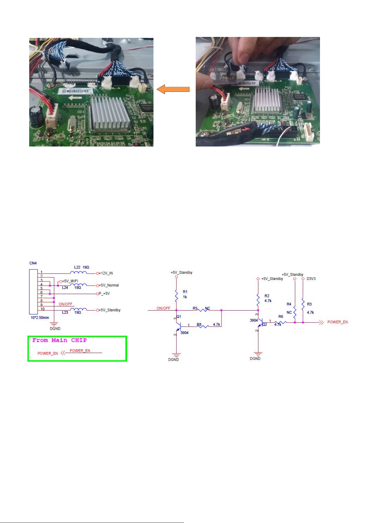
4.1 Power circuit
4.1.1 Power Input
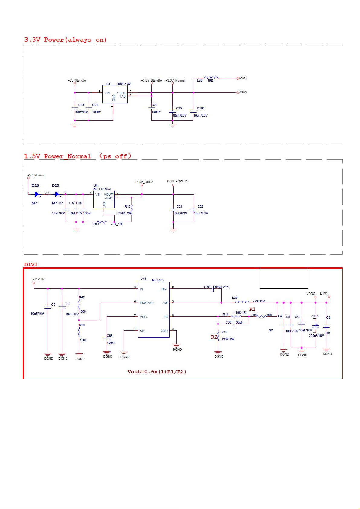
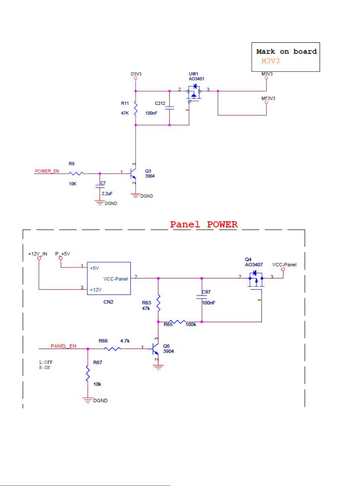
4.1.2 Power Supply
10
Page 11
Sharp LC-60LE644U Service manual
11
Page 12
Sharp LC-60LE644U Service manual
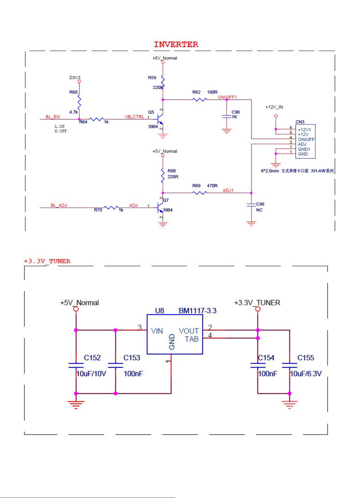
4.1.3 Inverter
12
Page 13
Sharp LC-60LE644U Service manual
4.1.4 Tuner power
13
Page 14
Sharp LC-60LE644U Service manual
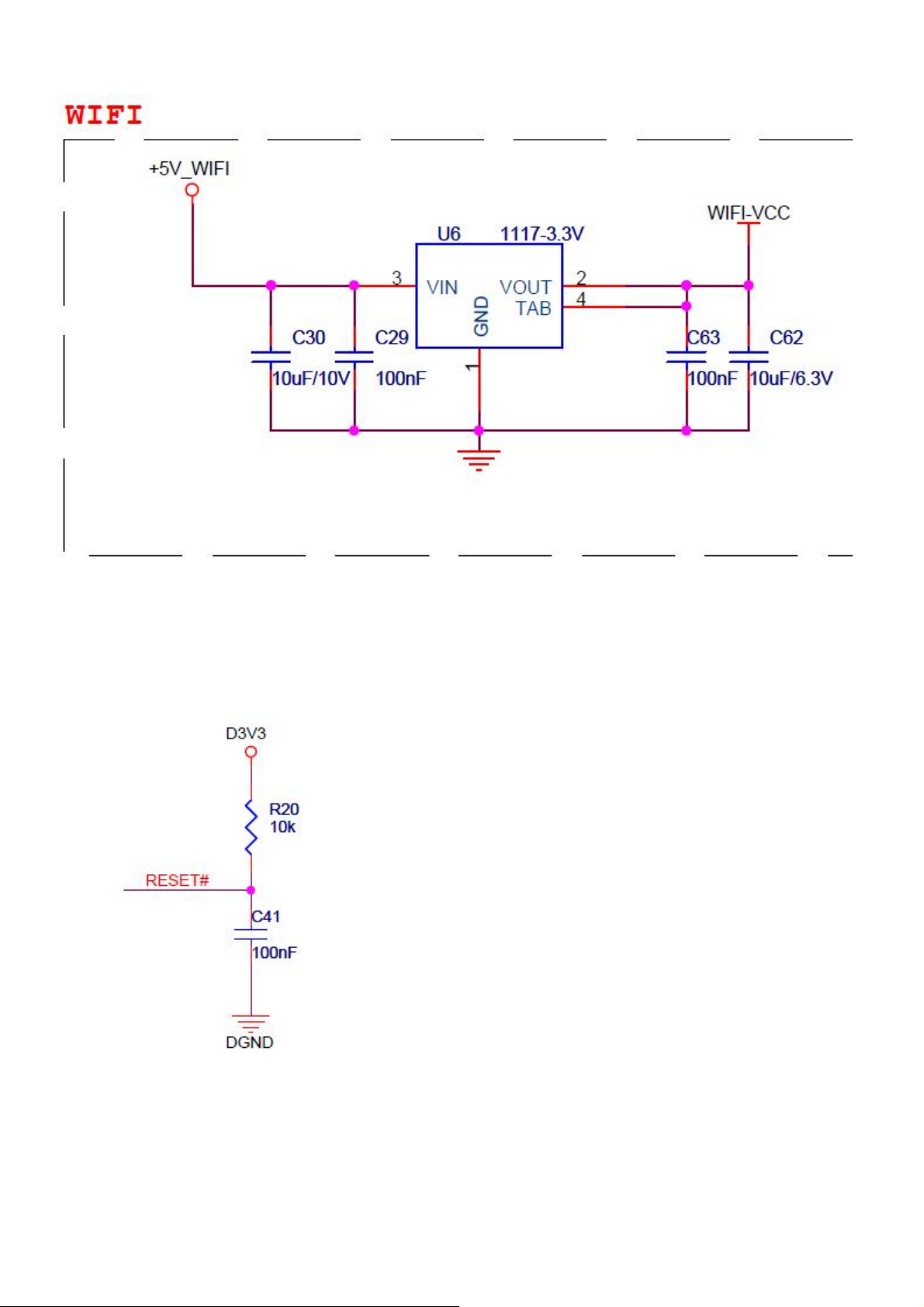
4.2 Reset circuit
14
Page 15
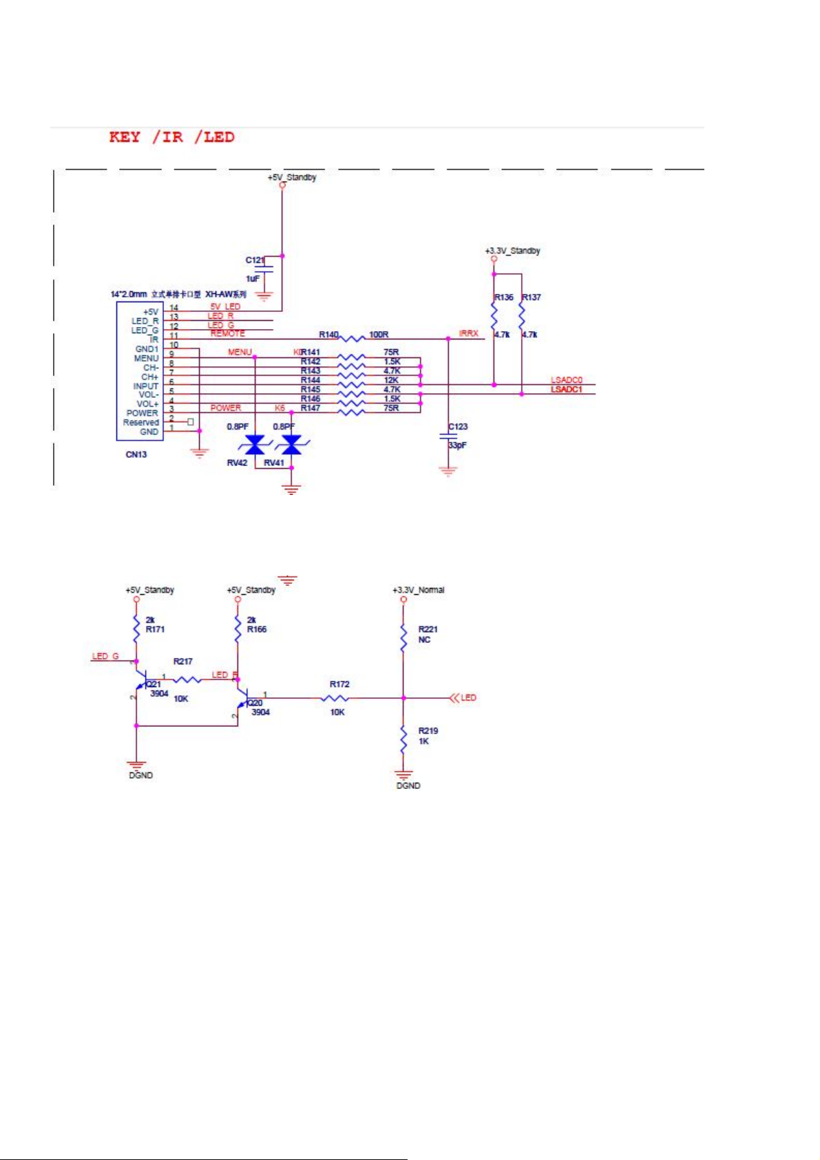
4.3 IR&KEY circuit
Sharp LC-60LE644U Service manual
15
Page 16

4.4 VGA INPUT
4.4.1 VGA Interface
Sharp LC-60LE644U Service manual
4.4.2 PC Audio
16
Page 17

4.5 SPDIF OUTPUT
Sharp LC-60LE644U Service manual
17
Page 18

4.6 AV& YPBPR
Sharp LC-60LE644U Service manual
18
Page 19

4.7 HDMI circuit
HDMI1
Sharp LC-60LE644U Service manual
HDMI2
19
Page 20

HDMI3
Sharp LC-60LE644U Service manual
ARC Control
20
Page 21

4.8 USB Circuit
Sharp LC-60LE644U Service manual
4.9 AMP Circuit
21
Page 22

Sharp LC-60LE644U Service manual
22
Page 23

4.10 Main controller RTK2986A
Sharp LC-60LE644U Service manual
23
Page 24

4.11 WIFI Control
Sharp LC-60LE644U Service manual
24
Page 25

5 Trouble shooting table
NG
OK
NG
OK
NG
electric
OK
NG
5.1 Power Troubleshooting
Sharp LC-60LE644U Service manual
Check the external power
supply(12V/5V/5VS)
Check the
Repair the
electric circuit
Repair the
power
Main Board
Check the voltage
(3.3V) of U3
Check the
voltage (1.1V) of
U11
1.Check the voltage (5V)
2.Check the voltage (1.1V) of U11
3.Check the voltage (3.3V) of U3
4.Check the voltage (1.5V) of U4
1.Repair the electric circuit (5V)
2.Repair the electric circuit (1.1V) of U11
3.Repair the electric circuit (3.3V) of U3
4.Repair the electric circuit (1.5V) of U4
25
Page 26

Sharp LC-60LE644U Service manual
NG
OK
NG
NG
OK
OK
correctly
correctly
NG
5.2 Display Troubleshooting
5.2.1 Display Troubleshooting (Dazzling Screen)
1.Check the LVDS cable
2.Check the connection of the LVDS cable
1.Change the correct
LVDS Cable
2.Connect the LVDS Cable
1.Check the screen voltage
2.Check if the software fit with the screen's feature
1.Repair the circuit of screen voltage
2.Update the correct software
Change the LED/LCD panel
1.Check the connection of CN1
2.Check the circuit of PCB
3.Change U3
Check LED/ LCD
panel
1.Check CN1
2.Check the LVDS signal of
CN1
26
Page 27

Sharp LC-60LE644U Service manual
NG
circuit
of
CN1
OK
NG
OK
OKNGOK
NG
NG
OK
5.2.2 Display Troubleshooting (White Screen)
Check the screen
voltage of CN1
Check the external
circuit of Q4
Check the LVDS signal
Repair the
external
Change
Q4
5.2.3 Display Troubleshooting (Black Screen)
Check the voltage of
1st/2nd/3rdpin of CN1
Repair the circuit of
1st/2nd/3rdpin of CN1
Change
U3
1.Check the driving
voltage of power board
2.Check the backlight
Repair the LVDS
signal circuit of CN1
1.Change power board
2.Change backlight board
Check the cables
27
Page 28

Sharp LC-60LE644U Service manual
OK
NG
OK
NG
OK
NG
OK
OK
NG
NG
OK
NG
5.3 Audio Troubleshooting(No Sound)
Check the Audio
input
Change or Debug
the Audio input
Repair the voltage (12V)
circuit of U9
Turn off Mute
Check CN15 Audio output
Check if it is
on Mute
Check the voltage
(12V) of U9
1.Check the connection of
. speaker cables
2.Check the speakers
3. Repair the circuit of Pin
15.16.27.28 of U2
4. Change U9
1. Check the voltage (12V) of Pin 15.16 of U2
2. Check the voltage (12V) of Pin 27.28 of U2
Check the signal between
CPU and amplifier IC
1. Repair the circuit between
CPU and amplifier IC
2. Change U9
Change U9
28
Page 29

Sharp LC-60LE644U Service manual
NG
OK
OK
NG
OK
NG
Troubleshooting
NG
2.
Repair
the
reset
circuit
OK
5.4 Function Troubleshooting
5.4.1 Function Troubleshooting(No work)
1.Keyboard no work
2.R/C no work
1.Check the Keyboard
2.Check the Remote control board
Check the voltage
(5V,3.3V,1.8V,1.2V)
No work
1.Repair the timing signal
Update the correct
software
Please check the Power
1.Check the timing signal
2.Check the reset circuit
Check the
software
OK
Change U2
29
Page 30

Sharp LC-60LE644U Service manual
OKOKOK
NG
OKNGNG
OK
OK
5.4.2 Function Troubleshooting(No Search Channels)
No Search
Check RF signal
Debug RF
signal machine
1.Check the U8voltage (3.3V)
2.Check the U7 voltage (3.3V)
1.Repair the U5 voltage (3.3V)
2.Repair the U7 voltage (3.3V)
NG
1.Repair U7 timing circuit
2.Repair U8 timing circuit
1.Check U7 I2C
2.Check U8 I2C
1.Check U7 timing signal
2.Check U8 timing signal
1.Check the connection of U7
2.Check the connection of U8
Change U2
1.Repair U7 or U8 I2C circuit
2.Check the connection of U7 or U8
3.Change U7 or U8
NG
1. Welding U7
2 .Welding U8
30
Page 31

Sharp LC-60LE644U Service manual
NGOKOKNGOK
OKOKOKNGNGNGOKOKOKOKOK
OK
signal
circuit
5.4.3 Function Troubleshooting(PC problem)
PC problem
Check the input machine
Debug the input
Check PC input cable
Change PC input cable
PC lose colour
Check RGB
circuit
ADC adjustment
Repair
RGB
Picture not in
PC picture not in
center
ADC adjustment
PC picture
Check the PC
synchronizing
signal
ADC Adjustment
Repair the PC
synchronizing
signal circuit
No signal
Check the PC
synchronizing
signal
Repair the PC
synchronizing
Change U2
Change U2
31
Page 32

Sharp LC-60LE644U Service manual
OKNGOK
NG
connector
OK
NGOKOK
NG
NGNGNG
OK
signal
OK
OK
OK
signal
5.4.4 Function Troubleshooting(HDMI、AV)
Debug the signal
Change the cable
Change HDMI
HDMI No signal
Check the input
Check the input
Check HDMI
AV No signal
Check the input
Debug the signal
Check the input
Change the cable
Check AV
circuit
Repair AV circuit
Repair HDMI
circuit
Check HDMI
circuit
Change U2
Change U2
32
Page 33

Sharp LC-60LE644U Service manual
NG
OK
OK
NG
input
cable
NGOKOK
OK
NG
NG
OK
OK
NG
5.4.5 Function Troubleshooting(YPbPr)
YPbPr lose colour
Check the
signal input
Check the
input cable
ADC
Debug the
input signal
Change the
Check YPbPr circuit
YPbPr No signal
Check the
signal input
Check the
input cable
Repair YPbPr circuit
Change U2
33
Page 34

Sharp LC-60LE644U Service manual
OK
OK
NG
OK
NG
OK
NG
OK
NG
connector
NG
OK
NGOKNG
OK
OK
NG
OK
5.4.6 Function Troubleshooting(USB,SPDIF)
Put the correct
multimedia files
Change USB
Repair the USB
circuit (5V)
USB No signal
Check if there are
multimedia files in
Check USB
Check the USB
voltage (5V)
Check USB
circuit
SPDIF No signal
Check SPDIF
signal input
Debug SPDIF
signal input
Check SPDIF
cable
Change
SPDIF cable
Check SPDIF
Change SPDIF
connector
Check SPDIF
circuit
Repair the
USB circuit (5V)
Change U2
Repair SPDIF
circuit
Change U2
34
Page 35

Sharp LC-60LE644U Service manual
6. Software update procedure
6.1 Enter factory menu mode method
6.1.1 Press “INPUT + 0000” display factory menu as photo 6.1
This factory menu contain following functions
1) ADC Adjust
2) Others
3) Lan Test
4) Wifi Test
5) Aging Mode
6) Init EEPROM
7) Factory Reset
8) Version Info
Photo 6.1 Photo 6.2
6.2 Software update procedure
6.2.1 Software update cautions
1) Do not remove the USB memory device or unplug the AC cord while the software is being
updated
2) Be sure to properly follow the whole procedure described below, step by step. Otherwise, For
example, the TV can not read the data in the USB memory device and software updating will
35
Page 36

Sharp LC-60LE644U Service manual
fail.
3) Make sure put .IMG file (the file must begin with ATSC) under the root directory of USB disk in
advance.
6.2.2 Software update steps
Step 1 Insert the USB memory device with the update file into the Service terminal on the TV.
Step 2 Press " MENU " to display interface , and Choose “information” as photo 6.3
Step 3 Press " Software Update" ---->”Manual Update”--->USB Update--->”YES’ to start update
as photo 6.4 and waiting the update progress as photo 6.5 until “install all’.
Step 4 Remove the USB memory device
Step 5 Turn off the power and unplug the AC cord. Plug the AC cord again and turn the power
back on.
Photo 6.3
36
Page 37

Sharp LC-60LE644U Service manual
Photo 6.4
Photo 6.5
37
Page 38

7. Connector define
Sharp LC-60LE644U Service manual
38
Page 39

Sharp LC-60LE644U Service manual
CN20. AMPLIFIER POWER SUPPLY CONNECTOR (4PIN/2.54)
CN1.LVDS INTERFACE (2×15PIN/2.0)
39
Page 40

Sharp LC-60LE644U Service manual
40
Page 41

Sharp LC-60LE644U Service manual
CN3. INVERTER CONNECTOR(6PIN/2.0)
CN4. BUILT-IN POWER SUPPLY CONNECTOR(10PIN/2.54)
CN15. SPEAKER CONNECTOR(4PIN/2.54)/(BTL)
41
Page 42

Sharp LC-60LE644U Service manual
J12. KEY&IR BOARD CONNECTOR(14PIN/2.0)
8. Critical components list
8.1 Critical components list for Main
Board
42
Page 43

Sharp LC-60LE644U Service manual
8.2 Critical components list for Power Board
8.2 Critical components list for Power Board
43
Page 44

Sharp LC-60LE644U Service manual
44
Page 45

Sharp LC-60LE644U Service manual
45
Page 46

Sharp LC-60LE644U Service manual
9. Mechanical Explosion Diagram
9.1 TV Set Explosion Diagram
TV Set Explosion Diagram parts description
46
Page 47

Sharp LC-60LE644U Service manual
47
Page 48

9.2 Packing Explosion Diagram
Sharp LC-60LE644U Service manual
48
Page 49

Sharp LC-60LE644U Service manual
49
Page 50

10. SUPPLIED ACCESSORIES
Sharp LC-60LE644U Service manual
50
 Loading...