

Page 1
TopPage
LC-60LE635E(B),RU(B)/636E(B),S(B)/638E(B)
SERVICE MANUAL
No. S82X760LE635B
LCD COLOUR TELEVISION
LC-60LE635E(B)/RU(B)
LC-60LE636E(B)/S(B)
MODELS
In the interests of user-safety (Required by safety regulations in some countries) the set should be restored to its original condition and only parts identical to those specified should be used.
LC-60LE638E(B)
OUTLINE
This model is based on the LC-60LE830E and partially modified.
For the contents not covered in this Service Manual, accordingly, please refer to the LC-60LE830E (S81T252LE830E)
Service Manual.
CONTENTS
OUTLINE AND DIFFERENCES FROM BASE MODEL
OUTLINE.............................................................i
DIFFERENCES FROM BASE MODEL...............i
SAFETY PRECAUTION
IMPORTANT SERVICE SAFETY PRE-
CAUTION........................................................ xiii
PRECAUTIONS A PRENDRE LORS DE
LA REPARATION............................................xiv
PRECAUTIONS FOR USING LEAD-FREE
SOLDER ..........................................................xv
CHAPTER 1. OPERATION MANUAL
[1] Parts Name.................................................... 1-1
[2] OPERATION MANUAL.................................. 1-7
CHAPTER 2. SPECIFICATIONS
[1] SPECIFICATIONS......................................... 2-1
CHAPTER 3. DIMENSIONS
[1] DIMENSIONS ................................................ 3-1
CHAPTER 5. ADJUSTMENT
[1] ADJUSTMENT PROCEDURE ......................5-1
CHAPTER 6. TROUBLESHOOTING TABLE
[1] TROUBLESHOOTING TABLE......................6-1
[2] LED flashing specification at the time of the
error...............................................................6-7
CHAPTER 7. MAJOR IC INFORMATIONS
[1] MAJOR IC INFORMATIONS.........................7-1
CHAPTER 8. OVERALL WIRING/SYSTEM BLOCK
DIAGRAM
[1] OVERALL WIRING DIAGRAM (LC-
60LE635E,RU/638E).....................................8-1
[2] OVERALL WIRING DIAGRAM (LC-
60LE636E/S).................................................8-2
[3] SYSTEM BLOCK DIAGRAM (LC-
60LE635E,RU/638E).....................................8-3
[4] SYSTEM BLOCK DIAGRAM (LC-
60LE636E/S).................................................8-4
CHAPTER 4. REMOVING OF MAJOR PARTS
[1] REMOVING OF MAJOR PARTS................... 4-1
[2] The location putting on the heat measure
sheet ..............................................................4-7
[3] Precautions for assembly............................... 4-9
Parts marked with " " are important for maintaining the safety of the set. Be sure to replace these parts with specified ones for maintaining the
safety and performance of the set.
Parts Guide
This document has been published to be used for
after sales service only.
The contents are subject to change without notice.
Page 2
LC-60LE635E(B),RU(B)/636E(B),S(B)/638E(B)
R9682
OUTLINE AND DIFFERENCES FROM BASE MODEL
OUTLINE
This model is based on the LC-60LE830E and partially modified.
For the contents not covered in this Service Manual, accordingly, please refer to the LC-60LE830E (S81T252LE830E) Service Manual.
DIFFERENCES FROM BASE MODEL
Ref
No.
PRINTED WIRING BOARD ASSEMBLIES
N MAIN Unit DKEYDF733FM51 DKEYDF733FM55 DKEYDF733FM57 DKEYDF733FM56 D Chanded
N R/C OPC Unit DUNTKF494FM02 N ICON Unit DUNTKF770FM51 DUNTKF770FM53 DUNTKF770FM53 DUNTKF770FM53 D Chanded
N TOUCH SENSOR Unit
N 3D IR TRANSMITTER Unit
N POWER Unit RUNTKA799WJN1 RUNTKA932WJQZ ← ←
LCD CONTRL Unit
N
LCD Panel Module
N 60" LCD Panel Module Unit
CABINET AND MECHANICAL PARTS
Please refer to a Parts Guide.
SUPPLIED ACCESSORIES/PACKING PARTS (NOT REPLACEMENT ITEM)
Please refer to a Parts Guide.
SERVICE JIG (USE FOR SERVICING)
Please refer to a Parts Guide.
Description LC-60LE830E
(S81T252LE830E)
RUNTKA869WJQ
Z
RUNTKA819WJQ
Z
RUNTK4909TPYN
R1LK600D3GW4BH R1LK600D3GV0AY
LC-60LE635E(B)
LC-60LE635RU(B)
DUNTKF494FM06
- - - - Delete
- - - - Delete
DUNTKF778FM53
LC-60LE638E(B) LC-60LE636E(B)
← ←
←
←
LC-60LE636S(B)
←
←
Inter-
chang
eabil-
ity
D Chanded
D
D Chanded
Note
Changed
Chanded
ddA-25MF008FKTNUD25MF008FKTNUD25MF008FKTNUD-tinU YEKN
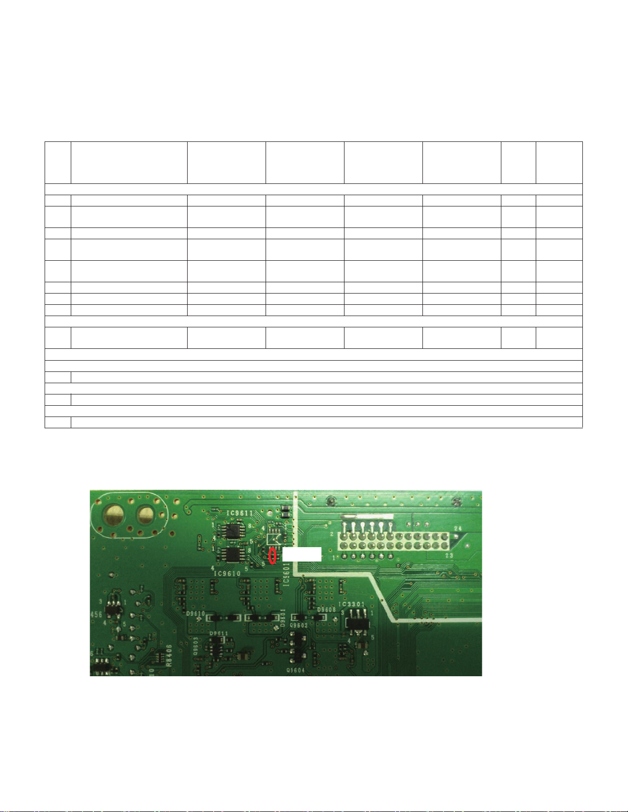
Note: In the case of changing the MAIN Unit ( DKEYDF733FM55/56/57)
*Please confirm that following part (R9682) is added in this unit
i
Page 3
LC-60LE635E(B),RU(B)/636E(B),S(B)/638E(B)
LC60LE635E
SAFETY PRECAUTION
Service Manual
IMPORTANT SERVICE SAFETY PRECAUTION
Service work should be performed only by qualified service technicians who are thoroughly familiar with all safety checks and the
servicing guidelines which follow:
WARNING
1. For continued safety, no modification of any circuit should be
attempted.
2. Disconnect AC power before servicing.
CAUTION: FOR CONTINUED PROTECTION
AGAINST A RISK OF FIRE REPLACE ONLY WITH
SAME TYPEFUSE.
F7001 (250V 5A)
• Use an AC voltmeter having with 5000 ohm per volt, or higher, sensitivity or measure the AC voltage drop across the resistor.
• Connect the resistor connection to all exposed metal parts having a
return to the chassis (antenna, metal cabinet, screw heads, knobs
and control shafts, escutcheon, etc.) and measure the AC voltage
drop across the resistor.
All checks must be repeated with the AC cord plug connection
reversed. (If necessary, a nonpolarized adaptor plug must be used
only for the purpose of completing these checks.)
Any reading of 0.75 Vrms (this corresponds to 0.5 mA rms AC.) or
more is excessive and indicates a potential shock hazard which
must be corrected before returning the monitor to the owner.
DVM
AC SCALE
BEFORE RETURNING THE RECEIVER (Fire &
Shock Hazard)
Before returning the receiver to the user, perform the following
safety checks:
3. Inspect all lead dress to make certain that leads are not pinched,
and check that hardware is not lodged between the chassis and
other metal parts in the receiver.
4. Inspect all protective devices such as non-metallic control knobs,
insulation materials, cabinet backs, adjustment and compartment
covers or shields, isolation resistor-capacitor networks, mechanical
insulators, etc.
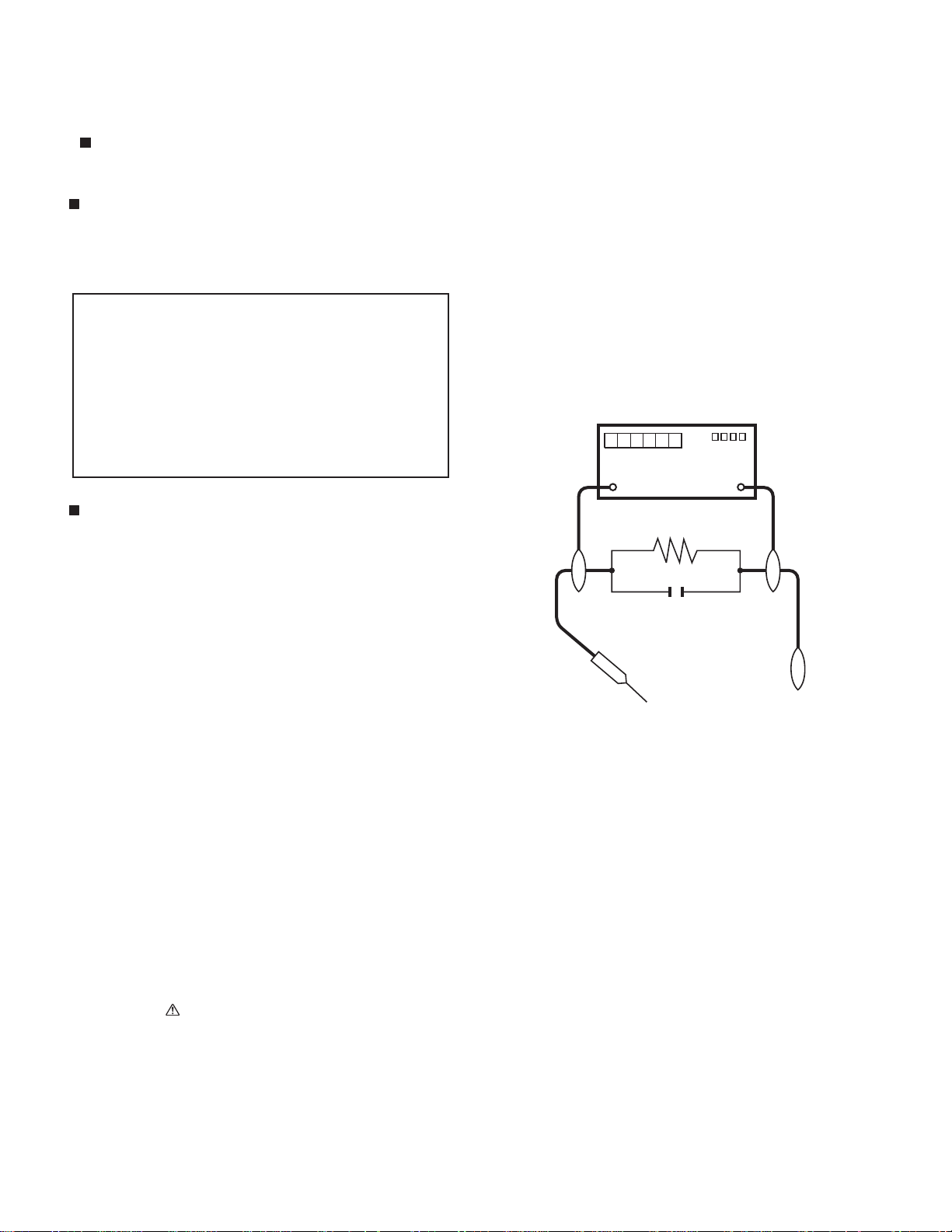
5. To be sure that no shock hazard exists, check for leakage current
in the following manner.
• Plug the AC cord directly into a 220-240 volt AC outlet.
• Using two clip leads, connect a 1.5k ohm, 10 watt resistor paralleled by a 0.15? F capacitor in series with all exposed metal cabinet
parts and a known earth ground, such as electrical conduit or electrical ground connected to an earth ground.
///////////////////////////////////////////////////////////////////////////////////////////////////////////////////////////////////////////////////////////////////////////////////////////////////////////////////////////////////////////
TO EXPOSED
METAL PARTS
1.5k ohm
10W
0.15µF
TEST PROBE
CONNECT TO
KNOWN EARTH
GROUND
SAFETY NOTICE
Many electrical and mechanical parts in LCD color television have
special safety-related characteristics.
These characteristics are often not evident from visual inspection, nor
can protection afforded by them be necessarily increased by using
replacement components rated for higher voltage, wattage, etc.
Replacement parts which have these special safety characteristics are
identified in this manual; electrical components having such features
are identified by " " and shaded areas in the Replacement Parts List
and Schematic Diagrams.
///////////////////////////////////////////////////////////////////////////////////////////////////////////////////////////////////////////////////////////////////////////////////////////////////////////////////////////////////////////
For continued protection, replacement parts must be identical to those
used in the original circuit.
The use of a substitute replacement parts which do not have the same
safety characteristics as the factory recommended replacement parts
shown in this service manual, may create shock, fire or other hazards.
xiii
Page 4
LC-60LE635E(B),RU(B)/636E(B),S(B)/638E(B)
PRECAUTIONS A PRENDRE LORS DE LA REPARATION
Ne peut effectuer la réparation qu' un technicien spécialisé qui s'est parfaitement accoutumé à toute vérification de sécurité et aux
conseils suivants.
AVERTISSEMENT
1.
N'entreprendre aucune modification de tout circuit. C'est dangereux.
Débrancher le récepteur avant toute réparation.
2.
CAUTION: FOR CONTINUED PROTECTION
AGAINST A RISK OF FIRE REPLACE ONLY WITH
SAME TYPEFUSE.
F7001 (250V 5A)
Utiliser un voltmètre CA d'une sensibilité d'au moins 5000Ω/V pour
•
mesurer la chute de tension en travers de la résistance.
Toucher avec la sonde d'essai les pièces métalliques exposées qui
•
présentent une voie de retour au châssis (antenne, coffret métallique, tête des vis, arbres de commande et des boutons, écusson,
etc.) et mesurer la chute de tension CA en-travers de la résistance.
Toutes les vérifications doivent être refaites après avoir inversé la
fiche du cordon d'alimentation. (Si nécessaire, une prise
d'adpatation non polarisée peut être utilisée dans le but de terminer ces vérifications.)
La tension de pointe mesurèe ne doit pas dépasser 0.75V (correspondante au courant CAde pointe de 0.5mA).
Dans le cas contraire, il y a une possibilité de choc électrique qui
doit être supprimée avant de rendre le récepteur au client.
VERIFICATIONS CONTRE L'INCEN-DIE ET LE
CHOC ELECTRIQUE
Avant de rendre le récepteur à l'utilisateur, effectuer les vérifications suivantes.
Inspecter tous les faisceaux de câbles pour s'assurer que les fils
3.
ne soient pas pincés ou qu'un outil ne soit pas placé entre le châssis et les autres pièces métalliques du récepteur.
Inspecter tous les dispositifs de protection comme les boutons de
4.
commande non-métalliques, les isolants, le dos du coffret, les couvercles ou blindages de réglage et de compartiment, les réseaux
de résistancecapacité, les isolateurs mécaniques, etc.
S'assurer qu'il n'y ait pas de danger d'électrocution en vérifiant la
5.
fuite de courant, de la facon suivante:
Brancher le cordon d'alimentation directem-ent à une prise de cou-
•
rant de 220-240V. (Ne pas utiliser de transformateur d'isolation
pour cet essai).
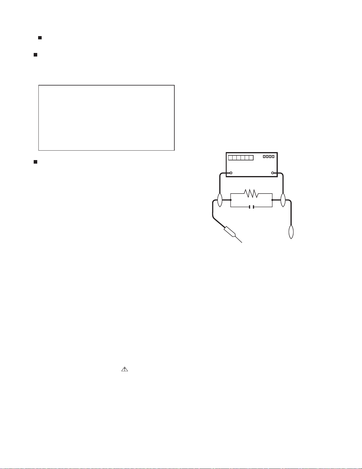
A l'aide de deux fils à pinces, brancher une résistance de 1.5 kΩ
•
10 watts en parallèle avec un condensateur de 0.15µF en série
avec toutes les pièces métalliques exposées du coffret et une terre
connue comme une conduite électrique ou une prise de terre
branchée à la terre.
/////////////////////////////////////////////////////////////////////////////////////////////////////////////////////////////////////////////////////////////////////////////////////////////////////////////////////////////////////////////
AUX PIECES
METALLIQUES
EXPOSEES
DVM
ECHELLE CA
1.5k ohm
10W
0.15
µ
SONDE D'ESSAI
F
BRANCHER A UNE
TERRE CONNUE
AVIS POUR LA SECURITE
De nombreuses pièces, électriques et mécaniques, dans les téléviseur ACL présentent des caractéristiques spéciales relatives à la sécurité, qui ne sont souvent pas évidentes à vue. Le degré de protection ne peut pas être nécessairement augmentée en utilisant des
pièces de remplacement étalonnées pour haute tension, puissance,
etc.
Les pièces de remplacement qui présentent ces caractéristiques sont
identifiées dans ce manuel; les pièces électriques qui présentent ces
particularités sont identifiées par la marque " " et hachurées dans la
liste des pièces de remplacement et les diagrammes schématiques.
/////////////////////////////////////////////////////////////////////////////////////////////////////////////////////////////////////////////////////////////////////////////////////////////////////////////////////////////////////////////
Pour assurer la protection, ces pièces doivent être identiques à celles
utilisées dans le circuit d'origine. L'utilisation de pièces qui n'ont pas
les mêmes caractéristiques que les pièces recommandées par l'usine,
indiquées dans ce manuel, peut provoquer des électrocutions, incendies, radiations X ou autres accidents.
xiv
Page 5
LC-60LE635E(B),RU(B)/636E(B),S(B)/638E(B)
PRECAUTIONS FOR USING LEAD-FREE SOLDER
Employing lead-free solder
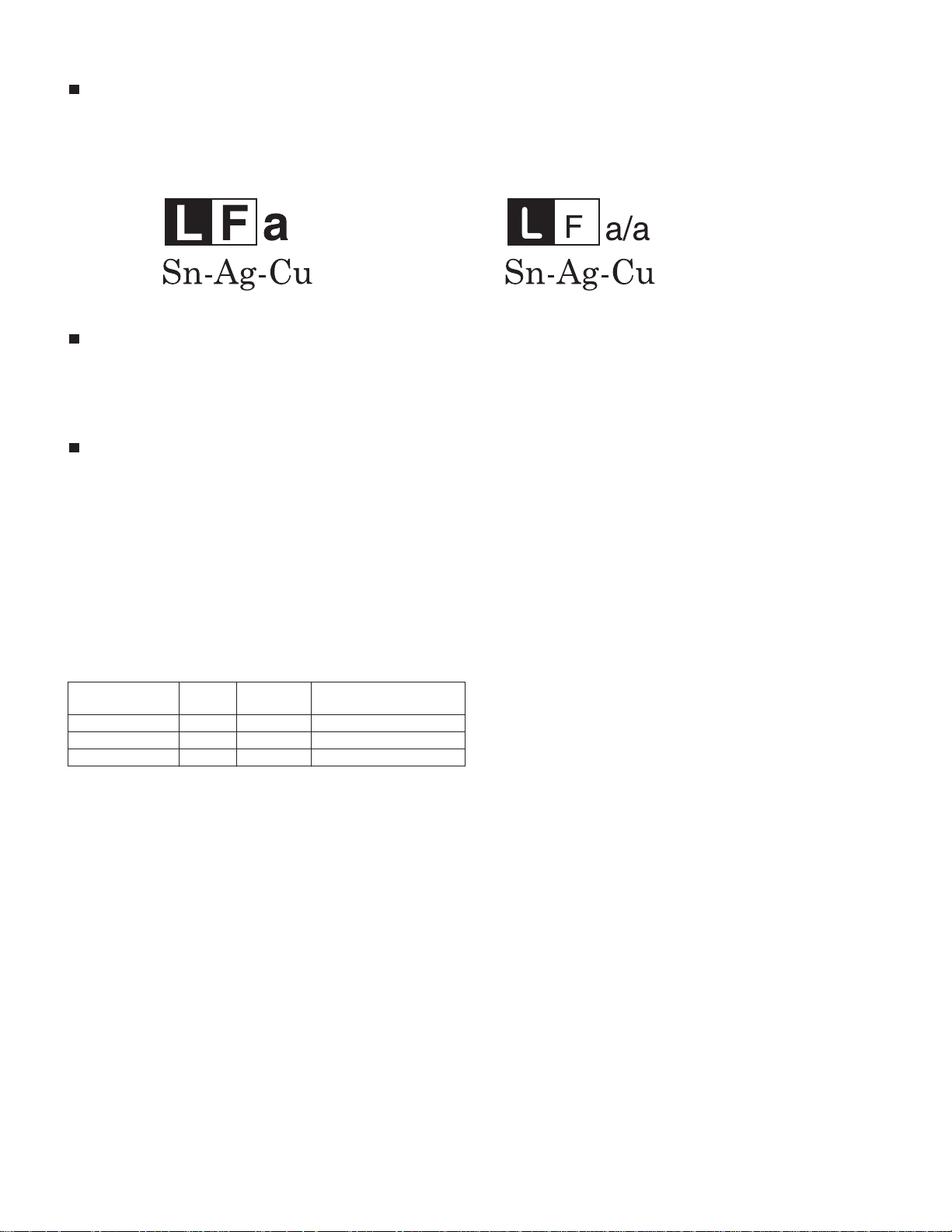
• “PWBs” of this model employs lead-free solder. The LF symbol indicates lead-free solder, and is attached on the PWBs and service manuals. The
alphabetical character following LF shows the type of lead-free solder.
Example:
Indicates lead-free solder of tin, silver and copper. Indicates lead-free solder of tin, silver and copper.
Using lead-free wire solder
• When fixing the PWB soldered with the lead-free solder, apply lead-free wire solder. Repairing with conventional lead wire solder may cause damage or accident due to cracks.
As the melting point of lead-free solder (Sn-Ag-Cu) is higher than the lead wire solder by 40 ?C, we recommend you to use a dedicated soldering
bit, if you are not familiar with how to obtain lead-free wire solder or soldering bit, contact our service station or service branch in your area.
Soldering
• As the melting point of lead-free solder (Sn-Ag-Cu) is about 220 ?C which is higher than the conventional lead solder by 40 ?C, and as it has poor
solder wettability, you may be apt to keep the soldering bit in contact with the PWB for extended period of time. However, Since the land may be
peeled off or the maximum heat-resistance temperature of parts may be exceeded, remove the bit from the PWB as soon as you confirm the
steady soldering condition.
Lead-free solder contains more tin, and the end of the soldering bit may be easily corroded. Make sure to turn on and off the power of the bit as
required.
If a different type of solder stays on the tip of the soldering bit, it is alloyed with lead-free solder. Clean the bit after every use of it.
When the tip of the soldering bit is blackened during use, file it with steel wool or fine sandpaper.
• Be careful when replacing parts with polarity indication on the PWB silk.
Lead-free wire solder for servicing
PARTS CODE
ZHNDAi123250E BL J ?0.3mm 250g (1roll)
ZHNDAi126500E BK J ?0.6mm 500g (1roll)
ZHNDAi12801KE BM J ?1.0mm 1kg (1roll)
PRICE
RANK
PART
DELIVERY
DESCRIPTION
xv
Page 6
LC60LE635E
CHAPTER 1. OPERATION MANUAL
[1] Parts Name
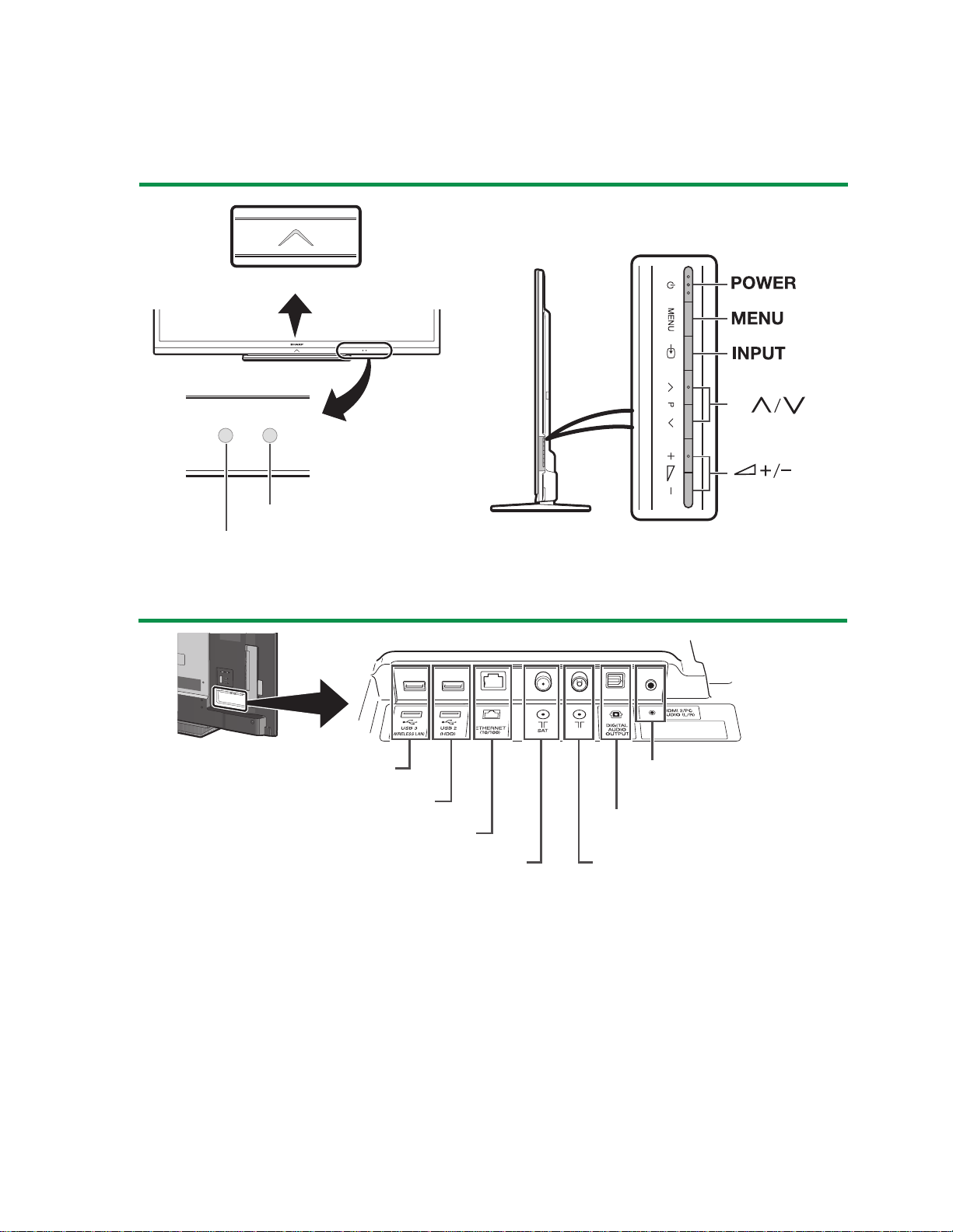
TV (front/side view)
Illumination LED
LC-60LE635E(B),RU(B)/636E(B),S(B)/638E(B)
Service Manual
P
OPC sensor
Remote control sensor
TV (rear view)
USB 3 ( WIRELESS LAN) port
USB 2 (HDD) port
ETHERNET (10/100) terminal
Satellite antenna terminal
(635/638 series only)
*
1
The HDMI 2 and PC terminals can both use the same audio input terminal (HDMI 2/PC
AUDIO (L/R)). However, the proper item must be selected in the “Audio select” menu.
HDMI 2/PC AUDIO (L/R)
1
jack
*
DIGITAL AUDIO OUTPUT
terminal
Antenna terminal
1 – 1
Page 7
LC-60LE635E(B),RU(B)/636E(B),S(B)/638E(B)
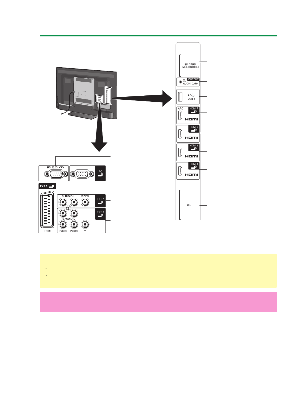
TV (rear view) — continued
SD CARD
(VIDEO STORE) slot
RS-232C terminal
PC terminal
EXT 1 (RGB) terminal
EXT 2 (VIDEO/AUDIO
(L/R)) terminal
EXT 3 (Component/
AUDIO (L/R)) terminal
OUTPUT (Headphones/
AUDIO (L/R)) terminal*
USB 1 port
HDMI 1 (HDMI/ARC)
terminal
HDMI 2 (HDMI) terminal
HDMI 3 (HDMI) terminal
HDMI 4 (HDMI) terminal
C.I. (COMMON
INTERFACE) slot
2
*2
When the headphone is connected to the OUTPUT terminal, the audio can be output
from the speakers.
WARNING
Excessive sound pressure from earphones and headphones can cause hearing loss.
Do not set the volume at a high level. Hearing experts advise against extended
listening at high volume levels.
Important information:
Satellite services are only available for the 635/638 model series.
1 – 2
Page 8
LC-60LE635E(B),RU(B)/636E(B),S(B)/638E(B)
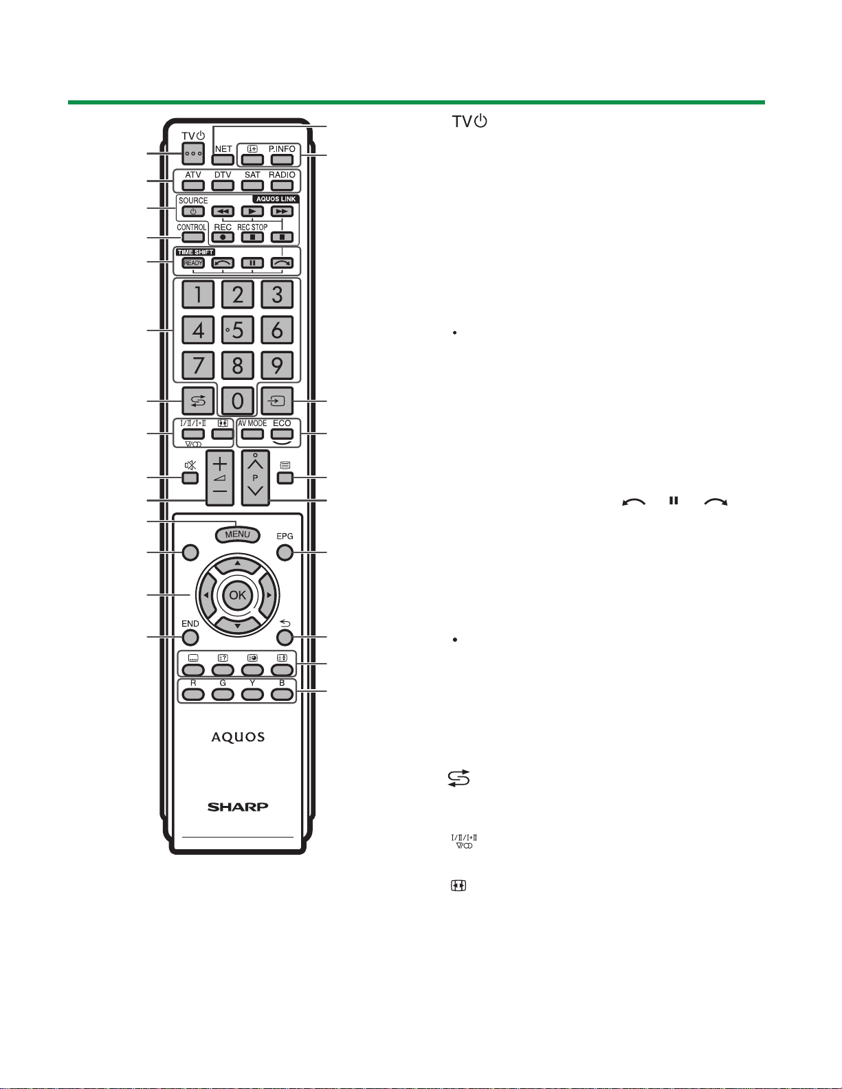
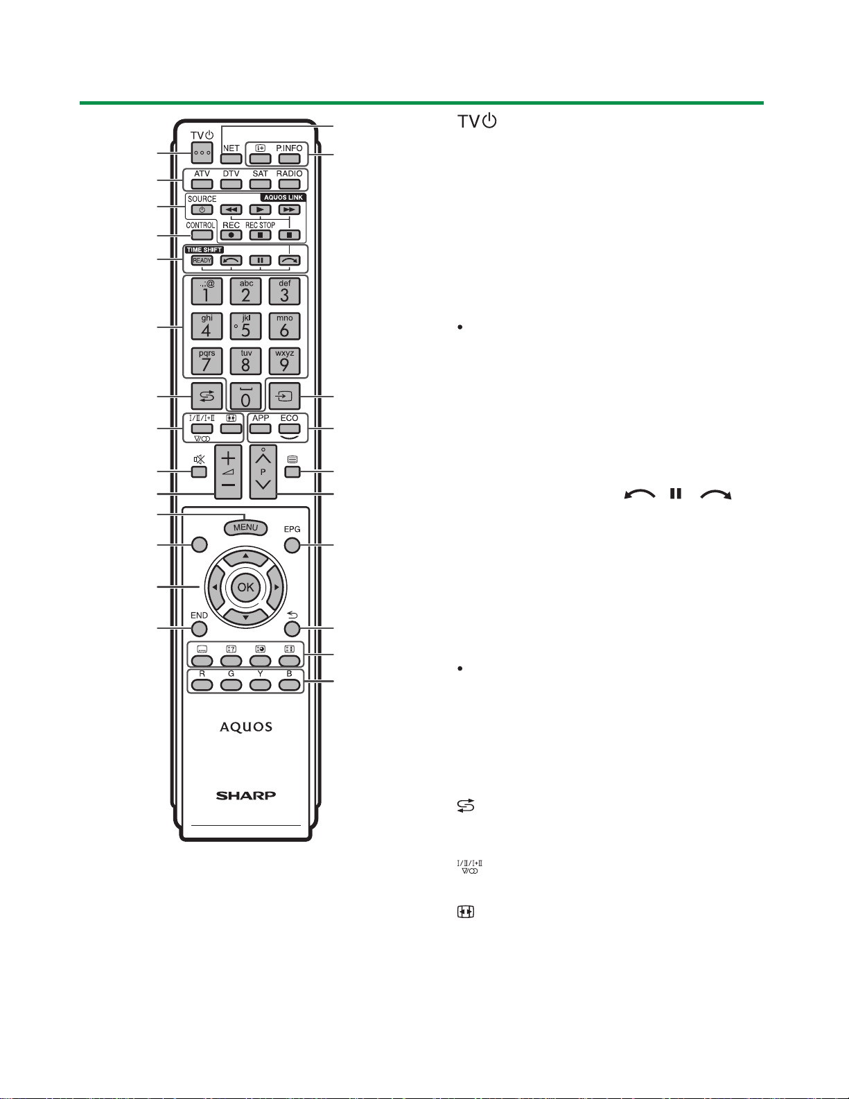
Remote control unit
1 1
2
3
4
5
6
7
8
9
10
11
12
(LC-60LE635E(B),RU(B)/636E(B).S(B))
15
6
17
18
19
20
21
1 (Standby/On)
2 ATV
Access conventional analogue TV mode.
DTV
Access digital TV mode.
SAT
Access satellite mode.
RADIO
DTV/SAT: Switch between radio and
data mode.
When only data broadcasting (no radio
broadcasting) is transmitted by DVB,
the radio broadcasting will be skipped.
3 AQUOS LINK buttons
4 CONTROL
Display a panel to operate some
functions on the screen.
NET: “NET MENU” screen on/off.
5 TIME SHIFT (READY/ / / )
Temporarily record a programme you are
watching.
13
14
22
23
24
6 Numeric buttons 0_9
Set the channel. Enter desired numbers.
Set the page in teletext mode.
When the five Nordic countries
(Sweden, Norway, Finland, Denmark
or Iceland) are selected in the country
setting from initial auto installation,
DTV services are four digits.
When another country is selected,
DTV services are three digits.
7 (Flashback)
Return to the previously selected
channel or external input.
8 (Sound mode)
Select a sound multiplex mode.
(Wide mode)
Select a wide mode.
1 – 3
Page 9

LC-60LE635E(B),RU(B)/636E(B),S(B)/638E(B)
9 (Mute)
TV sound on/off.
10 +/- (Volume)
Increase/decrease TV volume.
MENU
11
“Menu” screen on/off.
12 None
This button does not work on this
model.
13 / / /
(Cursor)
Select a desired item.
OK
Execute a command.
ATV/DTV/SAT: Display “CH list” when no
other “Menu” screen is running.
14
END
ATV/DTV/SAT: Exit the “Menu” screen.
NET: Return to the start page.
15 NET
Access Net TV.
16 (Display information)
Display the station information (channel
number, signal, etc.) on the screen.
P. INFO
Display programme information
transmitted through digital video
broadcasting (DTV/SAT only).
17 (INPUT)
Select an input source.
20 /
ATV/DTV/SAT: Select the TV channel.
NET: Scrolls pages up/down.
21 EPG
DTV/SAT: Display the EPG screen.
22 (Return)
ATV/DTV/SAT: Return to the previous
“Menu” screen.
NET: Return to the previous page (this
may not function for some services).
23 Buttons for useful operations
(Subtitle)
Switch subtitle languages on/off.
(Reveal hidden teletext)
(Subpage)
(Freeze/Hold)
Freeze a moving image on the screen.
Teletext: Stop updating teletext pages
automatically or release the hold mode.
24 R/G/Y/B (Colour) buttons
The coloured buttons are
correspondingly used to select the
coloured items on the screen (e.g., EPG,
MHEG-5, teletext).
Important information:
Satellite services are only available for
the 635 model series.
18
AV MODE
Select audio/video settings.
ECO(Standard/Advanced/Off)
Select “Energy save” setting.
19 (Teletext)
ATV: Display analogue teletext.
DTV/SAT: Select MHEG-5 or teletext for
DTV/SAT.
1 – 4
Page 10
LC-60LE635E(B),RU(B)/636E(B),S(B)/638E(B)
Remote control unit (LC-60LE638E(B))
1 1
2
3
4
5
6
7
8
9
10
11
12
13
14
15
17
18
19
20
21
22
23
24
1 (Standby/On)
6
2 ATV
Access conventional analogue TV mode.
DTV
Access digital TV mode.
SAT
Access satellite mode.
RADIO
DTV/SAT: Switch between radio and
data mode.
When only data broadcasting (no radio
broadcasting) is transmitted by DVB,
the radio broadcasting will be skipped.
3 AQUOSLINKbuttons
4 CONTROL
Display a panel to operate some
functions on the screen.
NET: “NET MENU” screen on/off.
5 TIME SHIFT (READY/ / / )
Temporarily record a programme you are
watching.
6 Numeric buttons 0_9
Set the channel. Enter desired numbers.
Set the page in teletext mode.
Inputting letters with the numeric
buttons is only available with MHP
services (Italy only).
When the five Nordic countries
(Sweden, Norway, Finland, Denmark
or Iceland) are selected in the country
setting from initial auto installation,
DTV services are four digits.
When another country is selected,
DTV services are three digits.
7 (Flashback)
Return to the previously selected
channel or external input.
8 (Sound mode)
Select a sound multiplex mode.
(Wide mode)
Select a wide mode.
1 – 5
Page 11

LC-60LE635E(B),RU(B)/636E(B),S(B)/638E(B)
9 (Mute)
TV sound on/off.
10 +/- (Volume)
Increase/decrease TV volume.
11 MENU
“Menu” screen on/off.
12 None
This button does not work on this
model.
13 / / / (Cursor)
Select a desired item.
OK
Execute a command.
ATV/DTV/SAT: Display “CH list” when no
other “Menu” screen is running.
“CH list” may not be displayed even
by pressing OK when executing the
MHP application. If so, you
can display “CH list” from “Menu” >
“CH list”.
END
14
ATV/DTV/SAT: Exit the “Menu” screen.
NET: Return to the start page.
15 NET
Access Net TV.
20 P /
ATV/DTV/SAT: Select the TV channel.
NET: Scrolls pages up/down.
21 EPG
DTV/SAT: Display the EPG screen.
22 (Return)
ATV/DTV/SAT: Return to the previous
“Menu” screen.
NET: Return to the previous page (This
may not function for some services).
23 Buttons for useful operations
(Subtitle)
Switch subtitle languages on/off.
(Reveal hidden teletext)
(Subpage)
(Freeze/Hold)
Freeze a moving image on the screen.
Teletext: Stop updating teletext pages
automatically or release the hold mode.
24 R/G/Y/B (Colour) buttons
The coloured buttons are
correspondingly used to select the
coloured items on the screen (e.g., EPG,
MHP, teletext).
16 (Display information)
Display the station information (channel
number, signal, etc.) on the screen.
P. INFO
Display programme information
transmitted through digital video
broadcasting (DTV/SAT only).
17 (INPUT)
Select an input source.
18
APP
Display the MHP application list (Italy
only).
ECO(Standard/Advanced/Off)
Select “Energy save” setting.
19 (Teletext)
ATV: Display analogue teletext.
DTV/SAT: Select teletext for DTV/SAT.
1 – 6
Page 12
[2] OPERATION MANUAL
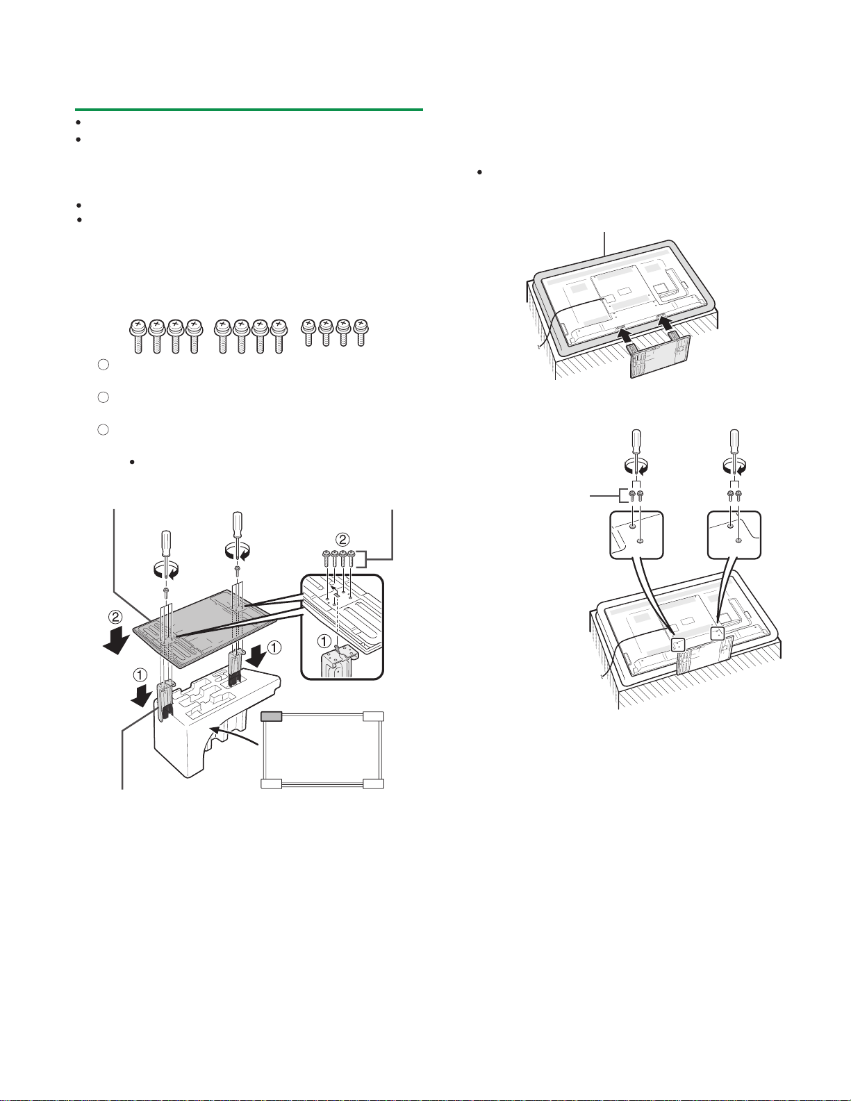
Attaching the stand unit
LC-60LE635E(B),RU(B)/636E(B),S(B)/638E(B)
Before attaching (or detaching) the stand, unplug the AC cord.
Before performing work, spread cushioning over the
surface on which you will be laying the TV. This will
prevent it from being damaged.
CAUTION
Attach the stand in the correct direction.
Be sure to follow the instructions. Incorrect
installation of the stand may result in the TV falling
over .
1 Confirm that there are twelve screws (eight long
screws and four short screws) supplied with the
stand unit.
1
2
Set the supporting post for the stand unit
onto the polystyrene foam.
2
Attach the stand base to the supporting
post.
3
Insert and tighten the eight screws into the
eight holes on the bottom of the stand base.
Hold the stand unit securely with one hand, and
then tighten the screws.
3 Insert the stand into the openings on the bottom
of the TV (hold the stand so it will not drop from
the edge of the base area).
Make sure that the stand is firmly inserted into the
TV. Improper installation may result in tilting of the
TV set.
Soft cushion
4 Insert and tighten the four screws into the four
holes on the rear of the TV.
swercsgnoLesabdnatS
Short screws
Supporting post
TV front
1 – 7
Page 13
LC-60LE635E(B),RU(B)/636E(B),S(B)/638E(B)
LC60LE635E
CHAPTER 2. SPECIFICATIONS
[1] SPECIFICATIONS
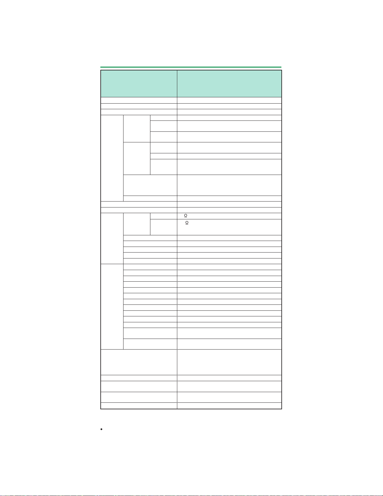
Specifications
Service Manual
Item
LCD panel
Video colour system PAL/SECAM/NTSC 3.58/NTSC 4.43/PAL 60
TV
function
Terminals Antenna VHF/UHF
Power requirement
Power consumption
(method IEC62087)
Operating temperature
*1
*2
*3
As a part of our policy of continuous improvement, SHARP reserves the right to make
design and specification changes for product improvement without prior notice. The
performance specification figures indicated are nominal values of production units.
There may be some deviations from these values in individual units.
TVstandard
Receiving
channel
TV-tuning system Auto Preset 999 ch (non-Nordic [DTV]),
Stereo/Bilingual A2/NICAM
RS-232C D-sub 9 pin male connector
EXT 1
EXT 2 RCApin (AV input/AUDIO L/R)
EXT 3 Component(AV input/Audio L/R)
HDMI 1 (EXT 4) HDMI (ARC)
HDMI 2 (EXT 5) HDMI
HDMI 3 (EXT 6) HDMI
HDMI 4 (EXT 7) HDMI
USB 1 USB
USB 2 (HDD) USB
USB 3 (WIRELESS LAN) USB
ETHERNET (10/100) Network connector
HDMI 2/PC AUDIO (L/R) Ø 3.5 mm jack*
DIGITAL AUDIO OUTPUT Optical S/PDIF digital audio output
C. I. (Common Interface) EN50221, R206001, CI Plus specification
OUTPUT/Headphones RCA pin (AUDIO L/R)/Ø 3.5 mm jack (audio
SD CARD (VIDEO
STORE)
The satellite channel’s frequency may vary according to satellites and antennas.
The HDMI 2 and PC terminals can both use the same audio input terminal.
Standby power consumption applies when the TV is set to not receive EPG data.
Analogue CCIR (B/G, I, D/K, L/L’)
Digital
(635 series )
Digital
(636 series )
VHF/UHF
CATV
Satellite
(635 series
only)
Satellite
(635 series
only)
LCD COLOUR TV (60"/152 cm),
LC-60LE635E(B)
LC-60LE635RU(B)
LC-60LE636E(B)
LC-60LE636S(B)
152 cm (60") X-Gen panel
DVB-T (2K/8K OFDM), DVB-C, DVB-S/S2
DVB-T (2K/8K OFDM),
DVB-T2 (1K/2K/4K/8K/16K/32K OFDM), DVB-C
IR A ch_E69 ch (Digital), E2_E69 ch, F2_F10 ch,
I21_I69 ch, IR A_IR J ch
Hyper-band, S1_S41 ch
950_2150 MHz*
Auto Preset 9999 ch (Nordic [DTV]),
Auto Preset 99 ch (ATV), Auto Label, Auto Sort,
Auto Preset 9999 ch (SAT [635 series only])
2xW01reifilpmaoiduA
75
Din type (analogue & digital)
F type (DVB-S/S2)
75
SCART (AV input, Y/C input, RGB input, TV output)
output)
SD card
Finnish, French, German, Greek, Hungarian,
Italian, Latvian, Lithuanian, Norwegian, Polish,
Portuguese, Russian, Slovak, Slovene, Spanish,
Swedish, Turkish, Ukrainian, Romanian
AC 220-240 V, 50 Hz
168 W
(0.1 W standby*
29.5 kg (with stand)
0 °C to + 40 °C
LC-60LE638E(B)
stod3x080,1x029,1noituloseR
1
2x)mm23xmm051(rekaepS
nip51bus-DinimCP
2
3
)
)dnatstuohtiw(gk5.62thgieW
,nainotsE,hsilgnE,hctuD,hsinaD,hcezCegaugnalDSO
2 – 1
Page 14
LC60LE635E
CHAPTER 3. DIMENSIONS
[1] DIMENSIONS
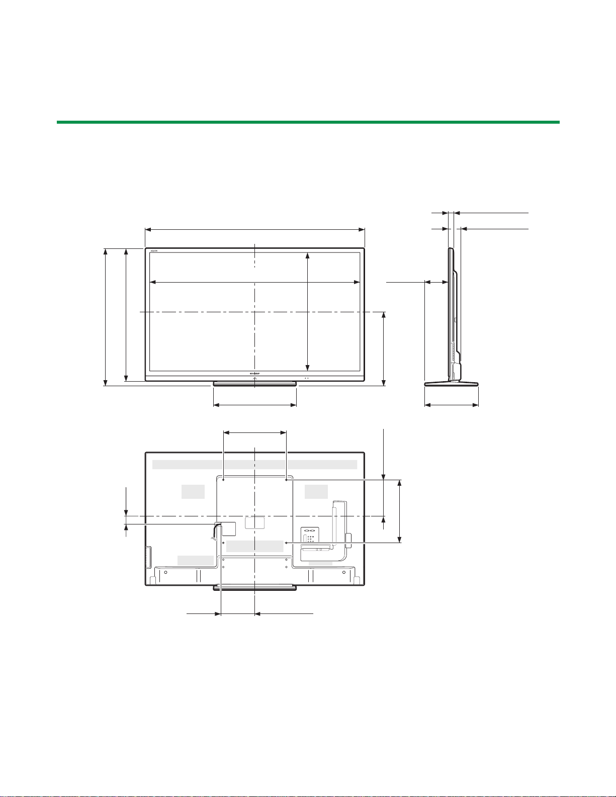
Dimensional drawings
LC-60LE635E(B),RU(B)/636E(B),S(B)/638E(B)
Service Manual
Unit:mm
(872)
(839)
(1329.12)
(1329,12)
(26.4) (26,4)
(1383)
*1
*1
*1
*1
(747.63)
(747,63)
(536)
(400)
(149)
(470)
(230)
(72.0) (72,0)
(333)
*2
(52)
(400)
(215)
*1
Active area
*2
Thinnest part
NOTE
Dimensions do not include protrusions such as screws and some parts.
3 – 1
Page 15
LC-60LE635E(B),RU(B)/636E(B),S(B)/638E(B)
LC60LE635E
CHAPTER 4. REMOVING OF MAJOR PARTS
Service Manual
[1] REMOVING OF MAJOR PARTS
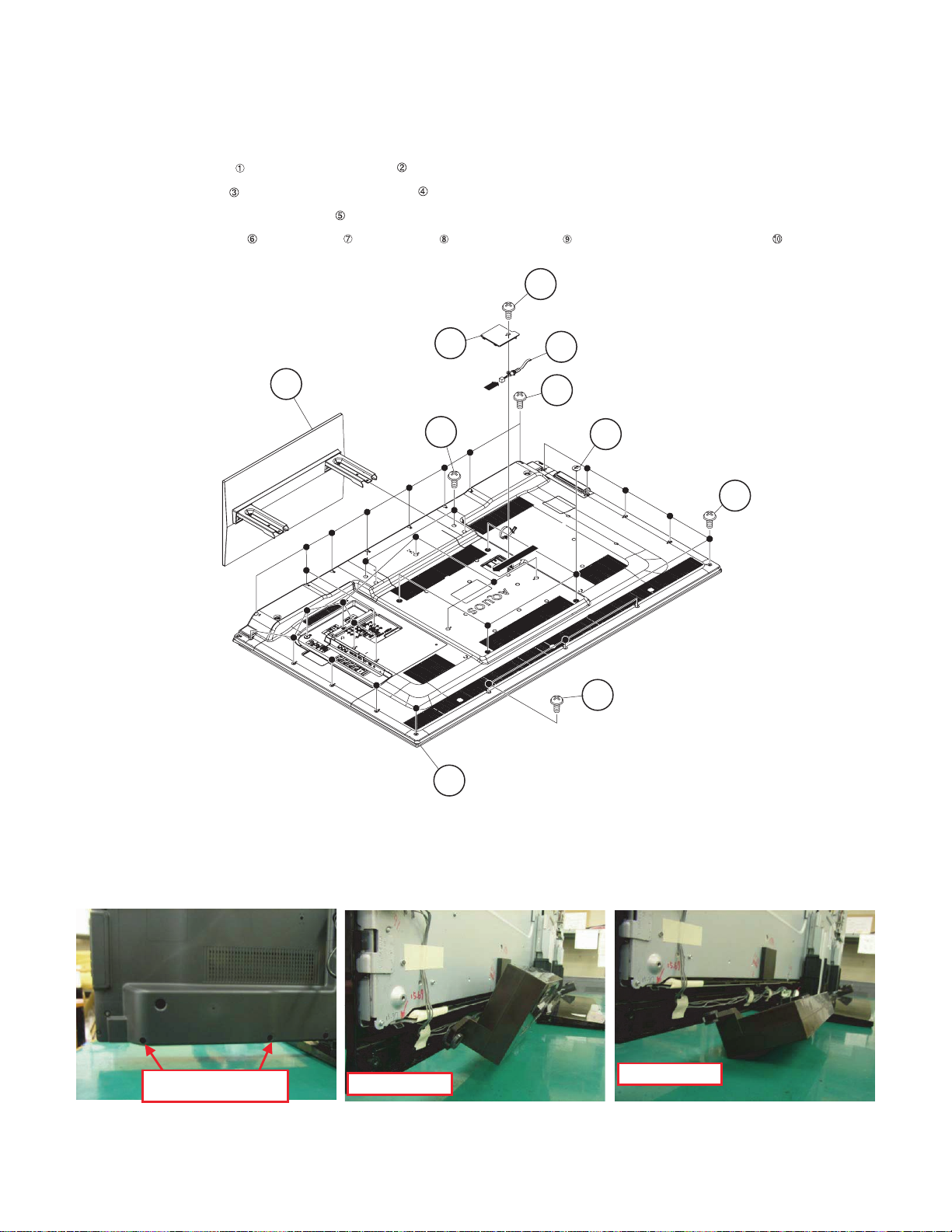
1. Removing of Stand Unit and Rear Cabinet Ass’y.
1. Remove the 4 lock screws and detach the Stand Unit .
2. Remove the 1 lock screw and detach the AC Cord Cover .
3. Disconnect AC wire and detach the AC Cord .
4. Remove the 4 VESA Covers , 9 lock screws , 3 lock screws and 17 lock screws and detach the Rear Cabinet Ass’y .
3
AC Cord Cover
2Stand Unit
4
[AC]
1
[AC]
Rear Cabinet Ass'y
10
5
AC Cord
7
VESA Cover
6
8
9
[Precaution when removing the rear cabinet]
If the rear cabinet is removed with the set upright, the speakers may fall; it results in connector disconnection. Therefore, never remove the rear cabinet with the set upright.
Be sure to remove the rear cabinet with the screen side down.
Screws for fixing Speaker
and Rear Cabinet
[Precaution when mounting the rear cabinet]
Put the speakers in place with the screen side down, and attach the rear cabinet.
Since the speakers are fixed by the rear cabinet, they cannot be fixed without the rear cabinet.
Speaker incline.
4 – 1
Speaker fall down.
Page 16
LC-60LE635E(B),RU(B)/636E(B),S(B)/638E(B)
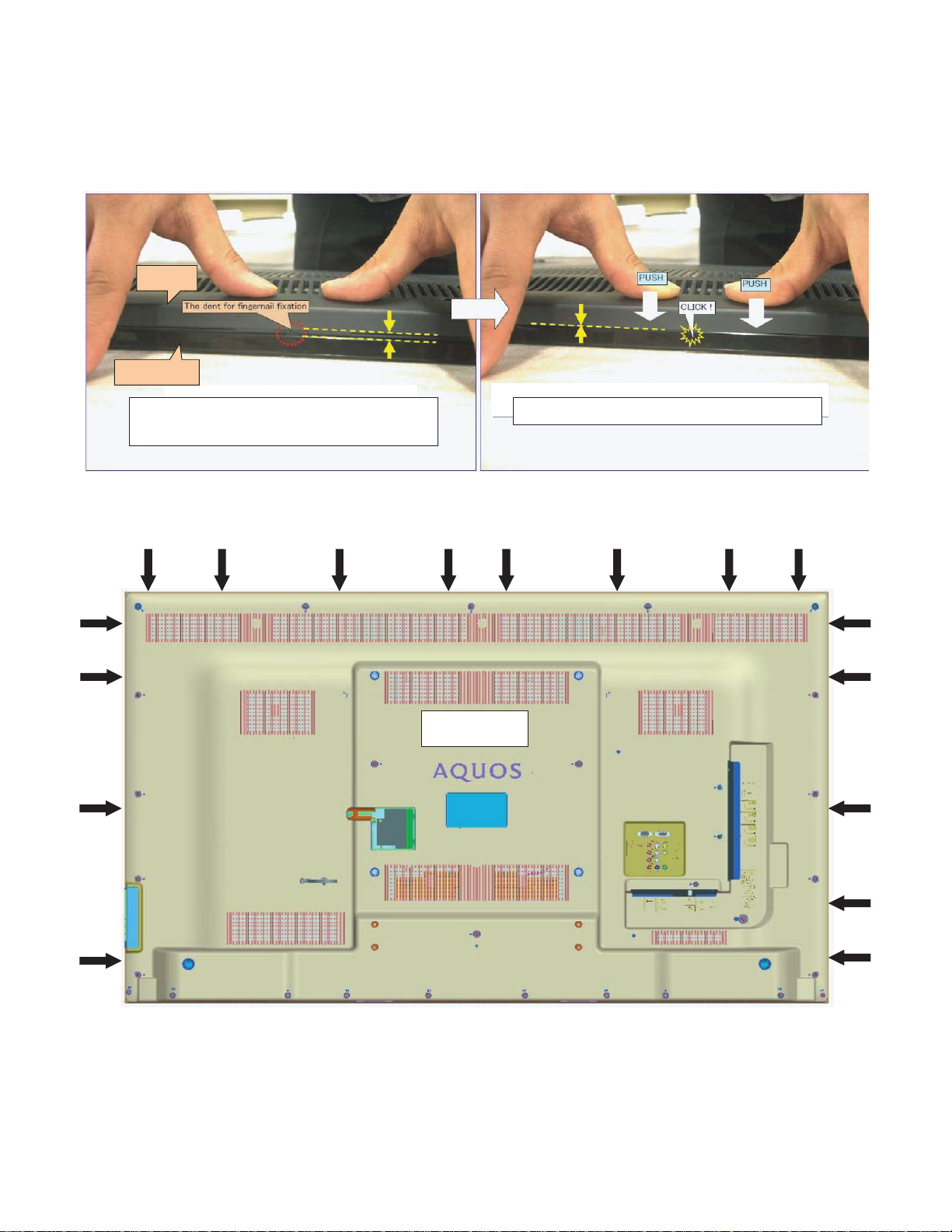
[Precautions when fixing the Rear Cabinet]
When fixing the Rear Cabinet, be careful not to catch the backlight LED harness, speaker harness and other harnesses in it.
• The hooks on the external wall of the Rear Cabinet are fitted in the Front Cabinet Ass’y. After putting the Rear Cabinet in place, fit the hooks
securely; then tighten the screws.
(Work method of Rear Cabinet fixation)
Rear Cabinet
(Mat parts)
Front Cabinet Ass'y
(Luster parts)
There is a gap without the fingernail fitting in completely only when covering
with Rear Cabinet.
It becomes the factor of a gap increase of Front Cabinet Ass'y/Rear Cabinet
and the Rear Cabinet misregistration.
(Front Cabinet Ass’y/Rear Cabinet fingernail fixation place)
17 places
Please tighten the screw after Rear Cabinet is firmly pushed, and the
fingernail is confirmed.
4 – 2
Page 17
LC-60LE635E(B),RU(B)/636E(B),S(B)/638E(B)
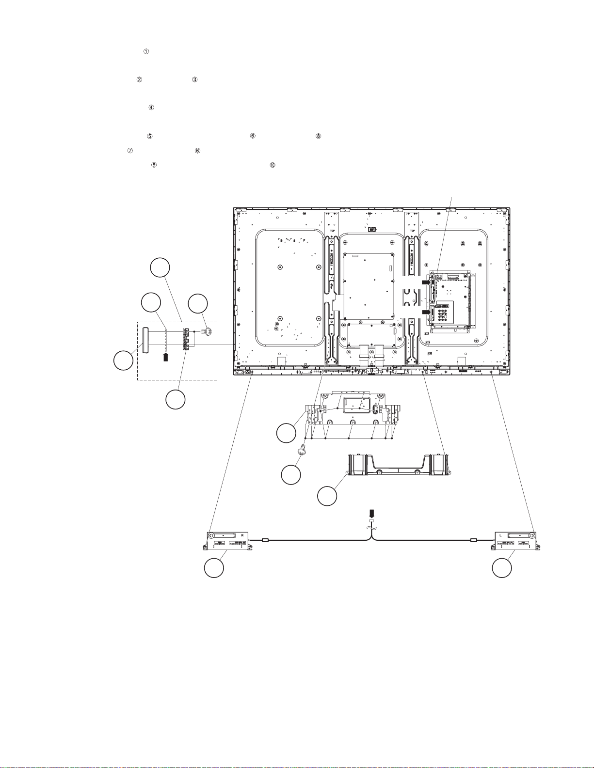
2. Removing of Speaker (L/R), KEY Unit and S-T-CON Angle.
1. Detach the Bottom Cover
2. Disconnect the SP wire.
3. Detach the Speaker (L) , Speaker (R) .
4. Disconnect the RC wire.
5. Detach the KEY Unit Ass’y .
6. Disconnect the KM wire.
7. Remove the 2 lock screws and detach the Key Button from Key Cover .
8. Detach the KEY Unit from Key Button .
9. Remove the 15 lock screws and detach the S-T-CON Angle .
MAIN Unit
KEY UnitAss'y
KEY Unit
Key Cover
4
[SP]
7
5
[RC]
8
[KM]
6Key Button
S-T-CON
Angle
10
9
1Bottom
Cover
[SP]
4 – 3
2Speaker (L)3Speaker (R)
Page 18
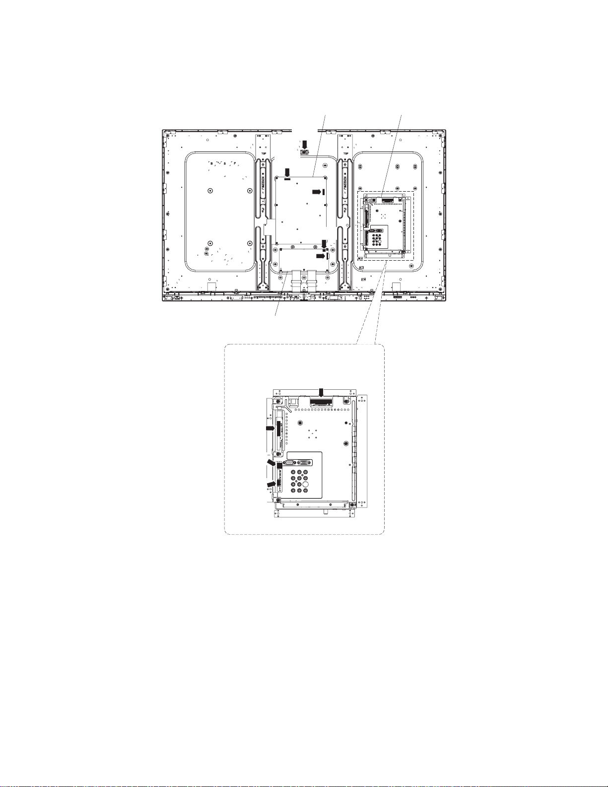
3. Removing of Connectors
1. Disconnect the following connectors from the MAIN Unit. (PD, LV, PL, Cl)
2. Disconnect the following connectors from the POWER Unit. (PD, LA)
3. Disconnect the following connectors from the LCD CONTROL Unit. (LW, PL)
[LA]
[LA]
[PD]
[PL]
[LW]
LC-60LE635E(B),RU(B)/636E(B),S(B)/638E(B)
MAIN UnitPOWER Unit
LCD Control Unit
MAIN Unit
[LV]
[PL]
[CI]
[PD]
4 – 4
Page 19
LC-60LE635E(B),RU(B)/636E(B),S(B)/638E(B)
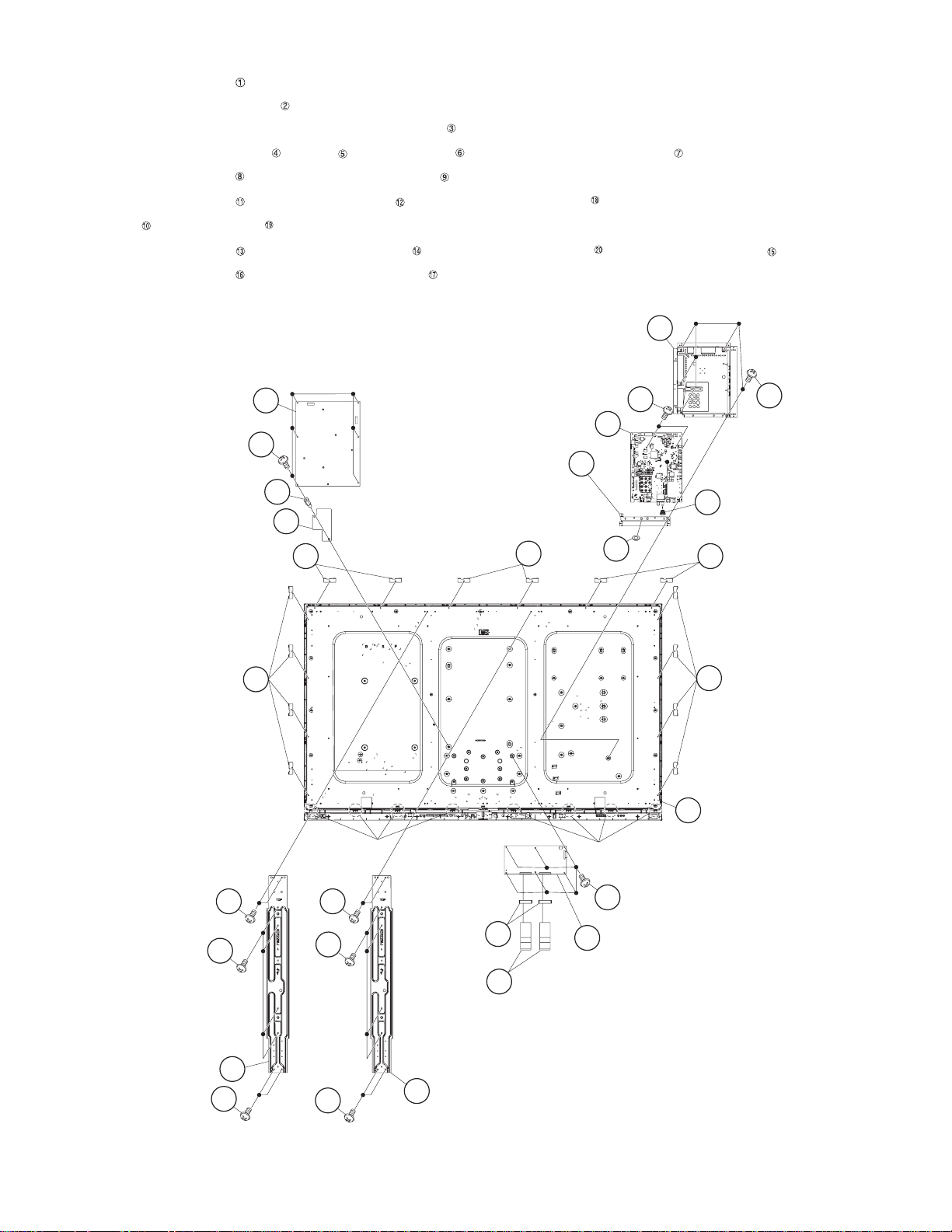
4. Removing of 60” LCD Panel Module Unit, LCD CONTROL Unit, MAIN Unit, POWER Unit.
1. Remove the 8 lock screws .
2. Detach the 14 Fixing Metal Angles .
3. Remove the 8 Hooks and detach the 60” LCD Panel Module Unit .
4. Remove the 2 Connecting Cords , 2 Cores and 6 lock screws and detach the LCD CONTROL Unit .
5. Remove the 5 lock screws and detach the MAIN PWB Shield .
6. Remove the 2 lock screws and detach the MAIN Unit and remove the Hexagon screw (except LC-60LE636E(B)/S(B)) and Terminal Angle
(Bottom) and Spring (Tuner) .
7. Remove the 6 lock screws and detach the POWER Unit and remove 1lock Tray Shaft and detach AC Cord Barrier .
8. Remove the 8 lock screws and detach the 2 Center Angles .
POWER Unit
Angle
Angle
2Fixing Metal
14
13
20
MAIN PWB
9
Shield
8
MAIN Unit
11
12
10Terminal Angle
(Bottom)
19
Spring
15AC Cord Barrier
2Fixing Metal
Fixing Metal
Angle
2
18
(Tuner)
2
Fixing Metal
Angle
2 Fixing Metal
Angle
1
16
Center
Angle
17
1
16
1
3
60" LCD Panel
Module Unit
Hook
1
5Core
Hook
6
7
LCD CONTROL Unit
4 Connecting
Cord
17 Center
Angle
4 – 5
Page 20
5. Removing of R/C OPC Unit, ICON Unit.
1. Detach the R/C OPC Unit .
2. Disconnect the RA wire.
3. Remove the 1 lock screw and detach the ICON Unit .
4. Disconnect the CI wire.
LC-60LE635E(B),RU(B)/636E(B),S(B)/638E(B)
Front Cabinet Ass'y
1R/C OPC Unit
[RA]
[CI]
3ICON Unit
2
4 – 6
Page 21

LC-60LE635E(B),RU(B)/636E(B),S(B)/638E(B)
[2] The location putting on the heat measure sheet
1. MAIN PWB Unit
PSPAZC805WJKZ
4 – 7
Page 22

2. LCD Control Unit
PSPAZC805WJKZ
LC-60LE635E(B),RU(B)/636E(B),S(B)/638E(B)
4 – 8
Page 23

LC-60LE635E(B),RU(B)/636E(B),S(B)/638E(B)
PSPAZC690WJZZ
PMLT-A676WJZZ
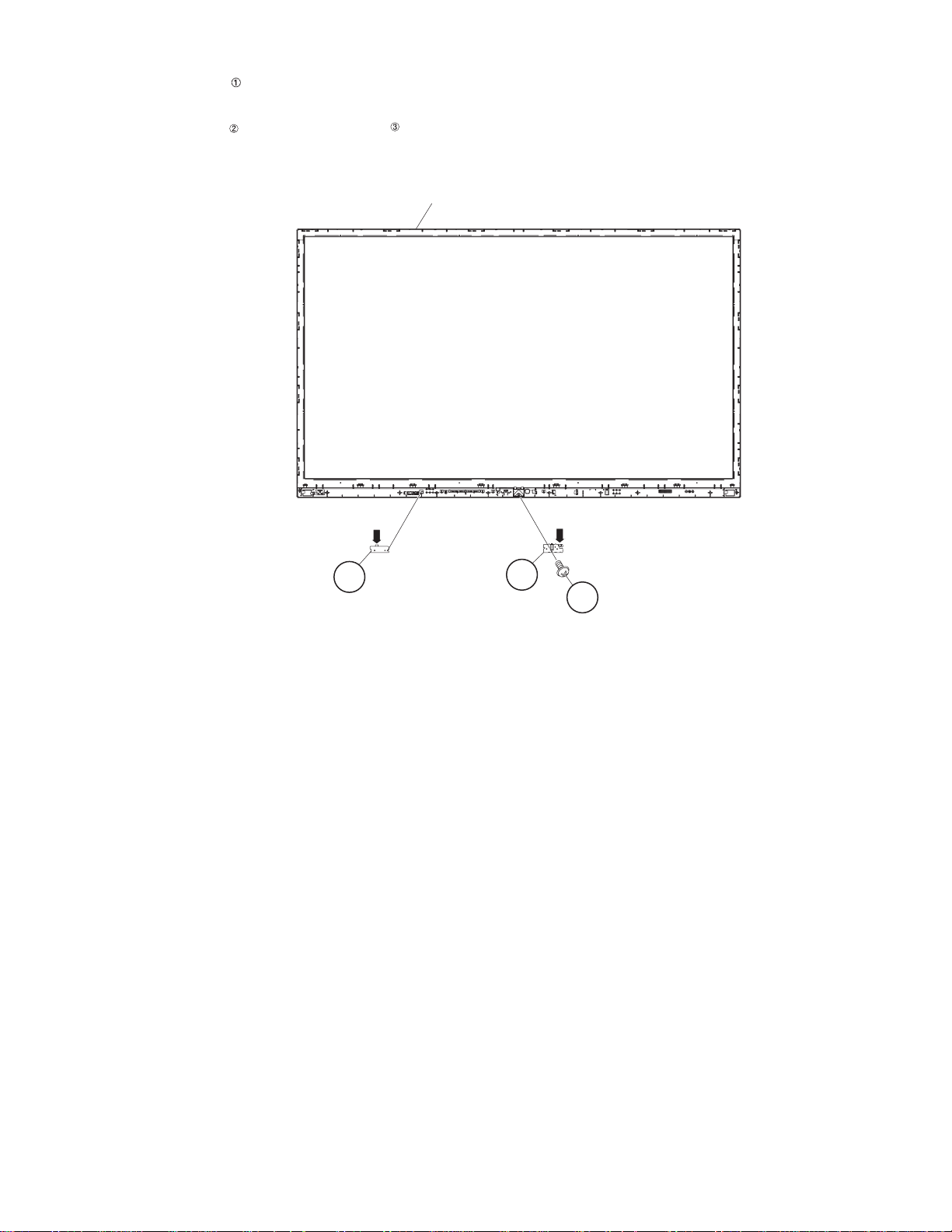
[3] Precautions for assembly
1. Points to be checked and precautions when servicing the unit
Mount the main PWB Ass’y on the backlight chassis and check that the EMI-prevention parts are not peeled and twisted from the access holes. (The
EMI-prevention parts, conductive nonwoven fabric gaskets, must be seen from the access holes.)
[Countermeasure]
Attach the conductive nonwoven fabric gaskets on the shielded case on the main PWB.
PSPAZC691WJZZ
PSPAZC691WJZZ
4 – 9
Page 24

State where the main PWB and shielded case are assembled
LC-60LE635E(B),RU(B)/636E(B),S(B)/638E(B)
Access hole
Access hole
The following is a drawing mounting the main PWB Ass’y on the backlight chassis. (The parts indicated by -> are the access holes for confirmation.)
(Main PWB Ass’y => State where the shielded case and RF terminal angle are mounted on the main PWB)
4 – 10
Page 25

LC-60LE635E(B),RU(B)/636E(B),S(B)/638E(B)
LC60LE635E
CHAPTER 5. ADJUSTMENT
Service Manual
[1] ADJUSTMENT PROCEDURE
1. Adjustment method after PWB and/or IC replacement due to repair
The unit is set to the optimum at the time of shipment from the factory.
If any value should become improper or any adjustment is necessary due to the part replacement, make an adjustment according to the following pro-
cedure.
1. Procure the following units in order to replace the main unit.
MAIN UNIT: DKEYDF733FM55 (LC-60LE635E(B)/RU(B))
MAIN UNIT: DKEYDF733FM56 (LC-60LE836E(B)/S(B))
MAIN UNIT: DKEYDF733FM57 (LC-60LE838E(B))
NOTE: [Caution when replacing IC (IC2001) in the main unit]
The above IC are Monitor microcomputer.
Before replacing the relevant part, procure the following parts in which the data have been rewritten.
IC2001 RH-iXD241WJNJQ Monitor microcomputer
NOTE: [Caution when replacing ICs (IC8401, IC3303) in the main unit]
When replacing either IC8401 or IC3302, exchange MAIN units for DKEYDF733FM55 (LC-60LE635E(B)/RU(B)), DKEYDF733FM56 (LC60LE636E(B)/S(B)) DKEYDF733FM57 (LC-60LE638E(B)).
Each part should not be individually exchanged.
IC8401 RH-iXD287WJQZQ Flash
IC3303 RH-iXD220WJQZQ Main CPU
NOTE: HDMI ROM Writing
After replacing IC1504, execute “HDMI EDID WRITE” on the page 5/20.
Please execute it after checking MODEL NAME & INCH SIZE. are correct.
If MODEL NAME & INCH SIZE. are not correct, set them previously. (Refer to 2.)
The ROM data based on information of MODEL NAME & INCH SIZE.
1) Enter the process adjustment mode in TV.
2) Use the cursor keys ( / ) and CH keys ( / ) of R/C to select the item [HDMI EDID WRITE] on the page 5/20.
3) It is completed with OK displayed.
2. After replacing the LCD panel or LCD control/MAIN UNIT, check MODEL NAME in the following procedure.
1) Enter the process adjustment mode in TV.
2) Use the cursor keys ( / ) and CH keys ( / ) of R/C to select the item [MODEL NAME] on the page 20/20.
3) Verify that the Model name is displayed.
4) If the Model name doesn’t match, select the values of the Model name with the VOL keys (+/-).
5) After selection in Step 4), press the OK key, and it is completed with OK displayed.
6) Use the cursor keys ( / ) and CH keys ( / ) of R/C to select the item [PANEL_SIZE] on the page 20/20.
7) Verify that the panel size is displayed.
8) If the size doesn’t match, select the values of the panel size with the VOL keys (+/-).
9) After selection in Step 8), press the OK key, and it is completed with OK displayed.
10)After setting [MODEL NAME] [PANEL_SIZE], unplug the AC power cord and plug it back in.
3. After replacing the LCD panel or LCD control PWB, adjust the VCOM in the following procedure.
1) Enter the process adjustment mode.
2) Use the cursor keys ( / ) and CH keys ( / ) of R/C to select the item [VCOM ADJ] on the page 10/20.
3) Press the OK key to verify that the adjustment pattern is displayed.
4) Use VOL keys (+/-) of R/C to adjust the flicker in the center of the screen to minimum.
5) When the optimal state is achieved in Step 4), press the OK key to turn the pattern to OFF.
5 – 1
Page 26

LC-60LE635E(B),RU(B)/636E(B),S(B)/638E(B)
2. Entering and exiting the adjustment process mode
1) Unplug the AC power cord of running TV set to force off the power.
2) While holding down the “VOL (-)” and “INPUT” keys on the set at once, plug in the AC power to turn on the power.
The letter “K” appears on the screen. This state is in Inspection mode.
3) Next, hold down the “VOL (-)” and “CH ( )” keys on the set at once.
Multiple lines of blue characters appearing on the screen indicate that the set is now in the adjustment Process mode.
If you fail to enter the adjustment process mode (the display is the same as normal startup), retry the procedure.
4) To exit the adjustment process mode after the adjustment is done, unplug the AC power cord to force off the power.
(When the power is turned off with the remote controller, once unplug the AC power cord and plug it in again. In this case, wait for 20 seconds or
so after unplugging.)
CAUTION:Use due care in handling the information described here lest the users should know how to enter the adjustment process mode.
If the settings are tampered with in this mode, unrecoverable system damage may result.
3. Description of display
(3) Present colour system
(2) Input that has been selected now (5) Inch setting and Model name display
1/20 INPUT1 AUTO EURO
MAIN Version
BOOT Version
Monitor Version
T-CON Version/LED CON Version
NET TV KEY/MAC
CI+INFO/SECURE BOOT
MARLIN
FRC Version
LAMP ERROR
MONITOR ERR CAUSE
1.00 (E 2010/**/** )
xxxxxxx
xxxxxxx
xxxxxxxx/xxxx
xxxxxxx
xxxxx/YES
xxxxxxx
xxxxxxx
0
1)xxxxxx 2)xxxxxx
3)xxxxxx 4)xxxxxx
NORMAL STANDBY CAUSE
ERROR STANDBY CAUSE
(1) Present page/number of total pages 2char/2char Decimal Number mark.
(2) Input that has been selected now TUNER/DTV/INPUT1/INPUT2/INPUT3/INPUT5/INPUT6/INPUT7/etc. ???
(5) Inch setting and Model name display Inch setting and Model name display
0
0 0 0 0
retemaraP)7(emanmetI)6(
noitacificeps yalpsiDnoitpircseD.oN
.cte 05/i0801/i085/i084/MACES/LAP/344N/853N/OTUAmetsys ruoloc tneserP)3( ???
NEDEWS/AISSUR/EPORUEyalpsid gnicudnI)4(
rahc 03 .xaMeman metI)6(
rahc 06 .xaMretemaraP)7(
5 – 2
Page 27

LC-60LE635E(B),RU(B)/636E(B),S(B)/638E(B)
4. List of adjustment process mode menu
The character string in brackets [ ] will appear as a page title in the adjustment process menu header.
1/20 [INFO]
.noisreV TOOBxxxxxxxnoisreV TOOB2
4 T-CON Version/LED CON Version xxxxxxxx/xxxx T-CON/LED CON Version
6 CI+INFO/SECURE BOOT xxxxx/YES CI+ Key Information/SECURE BOOT
xxxxxxxNILRAM7
xxxxxxxnoisreV CRF8
10 MONITOR ERR CAUSE 1)xxxxxx 2)xxxxxx
3)xxxxxx 4)xxxxxx
11 NORMAL STANDBY CAUSE 0 Situation that became standby at the end.
12 ERROR STANDBY CAUSE 0 0 0 0 Error standby cause
2/20 [INIT]
3/20 [TUNER ADJ]
4 PAL+TUNER ADJ(SMPTE) Enter PAL TUNER auto adjustment execution (SMPTE)
5 TUNER ADJ(SMPTE CH57) Enter TUNER auto adjustment execution (SMPTE CH57)
6 PAL+TUNER ADJ(SMPTE CH57) Enter PAL TUNER auto adjustment execution (SMPTE CH57)
7 TUNER CONTRAST A_GAIN 14 TUNER signal level adjustment
8 TUNER CONTRAST D_GAIN 2048 TUNER signal level adjustment
9 TUNER CONTRAST OFFSET 256 TUNER signal level adjustment
4/20 [PAL MAIN]
7 SECAM CONTRAST A_GAIN 14 SECAM contrast adjustment
8 SECAM CONTRAST D_GAIN 2048 SECAM contrast adjustment
9 SECAM CONTRAST OFFSET 256 SECAM contrast adjustment
11 N358 CONTRAST D_GAIN 2048 N358 contrast adjustment
12 N358 CONTRAST OFFSET 256 N358 contrast adjustment
5/20 [CEC TEST]
4 MONIDATA READ[TEMP/OPC] OFF MONITOR Temperature/ OPC Acquisition tool.
Last error standby cause.
(Excluding the error)
noitazilaitinIretnETINI YRTSUDNI1 to factory settings execution.
af ot noitazilaitinIFFO)cilbuP-(TINI YRTSUDNI2 ctory settings execution.(Public mode is
excluded)
aB-emitucA thgilkcaB6 cklight operating hours.
TES MARAP JDAretnETES MARAP JDA9
(Level appears in green on the upper right)
tnemtsujda LAPretnEJDA LAP1
tnemtsujda 853NretnEJDA 853N3
tset CEC IMDHretnETSET CEC IMDH1
TSET DRAC DSretnETSET DRAC DS5
).cte ,liated tnemtsujda( skrameRnoitpircseDmetIeniLegaP
noisrev erawtfos niaM)xxxxx(xxx1noisreV NIAM1
noisrev erawtfos rotinoMxxxxxxxnoisreV rotinoM3
sserddA CAM / YEK VT TENxxxxxxxCAM / YEK VT TEN5
.rorre pmal ot eud noitanimret fo rebmuN0RORRE PMAL9
gnittes FFO/NO edom cilbuPFFOEDOM CILBUP3
.sruoh gnitarepo niaM-emitucA retneC4
.teser sruoh gnitarepo niaMFFOTESER5
.teser sruoh gnitarepo thgilkcaBFFOTESER7
.teser rorre pmaLFFOTESER RORRE PMAL8
DAER CIV rof gnittes etanidrooc-X0SOPX CIV01
DAER CIV rof gnittes etanidrooc-Y0SOPY CIV11
DAER CIV rof gnittes epyt langiSNIAMEPYT LANGIS CIV21
noitcnuf noitisiuqca level erutciPFFODAER CIV31
noitucexe tnemtsujda otua RENUTretnEJDA RENUT1
noitucexe tnemtsujda otua RENUT LAPretnEJDA RENUT+LAP2
)ETPMS( noitucexe tnemtsujda otua RENUTretnE)ETPMS(JDA RENUT3
tnemtsujda MACESretnEJDA MACES2
tnemtsujda tsartnoc LAP41NIAG_A TSARTNOC LAP4
tnemtsujda tsartnoc LAP8402NIAG_D TSARTNOC LAP5
tnemtsujda tsartnoc LAP652TESFFO TSARTNOC LAP6
tnemtsujda tsartnoc 853N41NIAG_A TSARTNOC 853N01
GNITIRW DIDE IMDHretnEETIRW DIDE IMDH2
lanimret yromem BSU fo noitcepsni gnidaeRretnEMRET BSU TCEPSNI3
esuac ybdnats fo teseRretnETESER ESUAC6
5 – 3
Page 28

6/20 [COMP15KMAIN]
7/20 [HDTV]
8/20 [ANALOG PC]
9/20 [SCART]
2 SCART RGB ADJ (FASTSW) Enter SCART RGB ADJ (FASTSW) adjustment
10/20 [LUMAADJ]
LC-60LE635E(B),RU(B)/636E(B),S(B)/638E(B)
).cte ,liated tnemtsujda( skrameRnoitpircseDmetIeniLegaP
tnemtsujda level erutcip K51 tnenopmoCretnEJDA LLA K51PMOC1
eulav tnemtsujda NIAG Y041NIAG Y NIAM K51PMOC2
eulav tnemtsujda NIAG bC051NIAG BC NIAM K51PMOC3
eulav tnemtsujda NIAG rC051NIAG RC NIAM K51PMOC4
eulav tnemtsujda TESFFO Y46TESFFO Y K51PMOC5
eulav tnemtsujda TESFFO bC821TESFFO BC K51PMOC6
eulav tnemtsujda TESFFO rC821TESFFO RC K51PMOC7
tnemtsujda level oediv VTDHretnEJDA VTDH1
eulav tnemtsujda NIAG Y VTDH041NIAG Y VTDH2
eulav tnemtsujda bC VTDH051NIAG BC VTDH3
eulav tnemtsujda rC VTDH051NIAG RC VTDH4
eulav tnemtsujda TESFFO Y VTDH46TESFFO Y VTDH5
eulav tnemtsujda TESFFO bC VTDH821TESFFO BC VTDH6
eulav tnemtsujda TESFFO rC VTDH821TESFFO RC VTDH7
tnemtsujda level oediv GOLANA IVDretnEJDA CP GOLANA1
eulav tnemtsujda FFOTUC R46TESFFO R2
eulav tnemtsujda FFOTUC G46TESFFO G3
eulav tnemtsujda FFOTUC B46TESFFO B4
eulav tnemtsujda EVIRD R44NIAG R5
eulav tnemtsujda EVIRD G44NIAG G6
eulav tnemtsujda EVIRD B44NIAG B7
tnemtsujda level BGR TRACSretnEJDA BGR TRACS1
eulav tnemtsujda FFOTUC R TRACS46FFOTUC R TRACS3
eulav tnemtsujda FFOTUC G TRACS46FFOTUC G TRACS4
eulav tnemtsujda FFOTUC B TRACS46FFOTUC B TRACS5
eulav tnemtsujda NIAG R TRACS44NIAG R TRACS6
eulav tnemtsujda NIAG G TRACS44NIAG G TRACS7
eulav tnemtsujda NIAG B TRACS44NIAG B TRACS8
)D2( tnemtsujda saib nommoC46 JDA MOCV1
11/20 [LEV]
12/20 [M EEP SET]
3 MONITOR EEP READ / WRITE WRITE MONITOR EEPROM READ/WRITE Setting/execution
13/20 [M TEST PATTERN]
2 LCD TEST PATTERN1 NOT SUPPORT
4 LCD TEST PATTERN3 NOT SUPPORT
5 LCD TEST PATTERN4 NOT SUPPORT
14/20
2 TCON Version EXT.2
3 TCON Version EXT.3
4 TCON Version EXT.4
eulav tnemtsujda EVIRD R0)OL( NIAG R1
eulav tnemtsujda EVIRD G0)OL( NIAG G2
eulav tnemtsujda EVIRD B0)OL( NIAG B3
eulav tnemtsujda EVIRD R0)IH( NIAG R4
eulav tnemtsujda EVIRD G0)IH( NIAG G5
eulav tnemtsujda EVIRD B0)IH( NIAG B6
gnittes tuo-emit noitacinummoc niam eht dna rotinoMNOTUO EMIT ROTINOM1
gnittes erutarepmet XAM ROTINOM95PMET XAM ROTINOM2
gnisserdda yrartibra MORPEE ROTINOM0 x0RDA PEE ROTINOM4
noitacificeps atad yrartibra MORPEE ROTINOM0 x0ATAD PEE ROTINOM5
yalpsid rellortnoc DCL ni-tliub htiw nrettaPNRETTAP TSET DCL1
FFO2NRETTAP TSET DCL3
xxxxx1.TXE noisreV NOCT1
5 – 4
Page 29

LC-60LE635E(B),RU(B)/636E(B),S(B)/638E(B)
15/20 [FR REGI]
2 CROSSTALK TH1
3 CROSSTALK TH2
4 CROSSTALK TH3
5 CROSSTALK TH4
6 CROSSTALK GAIN1
7 CROSSTALK GAIN2
8 CROSSTALK GAIN3
16/20
17/20
18/20
19/20 [ETC]
1 ERROR STANDBY CAUSE1 NO RECORD ERROR STANDBY CAUSE
2 ERROR STANDBY CAUSE2 NO RECORD
3 ERROR STANDBY CAUSE3 NO RECORD
4 ERROR STANDBY CAUSE4 NO RECORD
5 ERROR STANDBY CAUSE5 NO RECORD
20/20 [ETC]
3 MONITOR ERROR CAUSE RESET OFF Reset of monitor error cause
0x 0
0x 0
0x 0
).cte ,liated tnemtsujda( skrameRnoitpircseDmetIeniLegaP
retnEEDOM JDA KLATSSORC1
xxxxxzHG4.2 DISS IFIW1
xxxxxzHG 5 DISS IFIW2
xxxxxzHG4.2 ISSR IFIW3
xxxxxzHG 5 ISSR IFIW4
xxxxxzHG 5 EMIT IFIW5
xxxxxTSET ISSR IFIW6
xxxxxTLUSER ISSR IFIW7
etirW/daeRDAERETIRW/DAER1
sserdda evalS0EVALSSSERDDA/EVALS2
0 x0SSERDDA RETSIGER3
0 x0ATAD ETIRW4
0 x0ATAD DAER5
06TNERRUC KCEHC TROHS01
WOLWS TNERRUC11
Register address
Writing data
Reading data
noitucexe tnemtsujda GB CGA-FR6GB CGA FR1
noitucexe tnemtsujda GKD CGA-FR5KD CGA FR2
noitucexe tnemtsujda I CGA-FR6I CGA FR3
noitucexe tnemtsujda 'L/L CGA-FR4'L/L CGA FR4
.esuac yb dnats teseRFFOTESER ESUAC YBDNATS6
.MORPEE ot seulav gnittes gnitirWFFOEVAS PEE1
.MORPEE morf seulav gnittes gnidaeRFFOREVOCER PEE2
EMAN LEDOME038ELEMAN LEDOM4
.gnittes ezis lenaP06EZIS LENAP5
galF pureVretnEELBANE GALF PUREV6
TIMIL LENAPNOTIMIL LENAP7
TIMIL EGNAR LENAPxxxTIMIL EGNAR LENAP8
thgil kcaB DEL kcehCretnEEDOM KCEHC TROHS9
)yrotcaf fo recudorp rof( gnivres nehw hcuot t'noD0 x0RDA PEE TCUDORP21
)yrotcaf fo recudorp rof( gnivres nehw hcuot t'noD0 x0ATAD PEE TCUDORP31
)yrotcaf fo recudorp rof( gnivres nehw hcuot t'noD1YROTCAF TCUDORP41
5 – 5
Page 30

5. Special features
1. NORMAL STANDBY CAUSE (Page 1/20)
Display of a cause (code) of the last standby.
The cause of the last standby is recorded in EEPROM whenever it is possible.
Checking this code will be useful in finding a problem when you repair the troubled set.
2. EEP SAVE (Page 20/20)
Storage of EEP adjustment value.
3. EEP RECOVER (Page 20/20)
Retrieval of EEP adjustment value from storage area.
4. MONITOR ERR CAUSE (Page 1/20)
Display of a cause (code) of Error from Monitor microcomputer.
The cause of Error is recorded in EEPROM whenever it is possible.
Checking this code will be useful in finding a problem when you repair the troubled set.
1) This displays Error code and time when the error occurred.
The latest error is displayed on “1)”.
The error that happens ahead of “1)” is displayed on “2)”.
2) The character depends on the way how to acquire Time Information.
T: Time is acquired from digital broadcasting
This doesn’t contain “Time offset” which is considered a time difference and Daylight-Saving Time, etc. ...
U: Time is acquired from analog broadcasting (teletext)
B: Accumulation time of Backlight
In the case that Time information cannot be acquired, “B” is displayed.
LC-60LE635E(B),RU(B)/636E(B),S(B)/638E(B)
Example) In this example, it is shown that the error occurred 3 times.
1) 16 T07/01/01 12:03 Error code: 16 (lamp error) Time: 07/01/01 12:03
* It is latest Error.
* Time is acquired from digital broadcasting.
* Time is UTC which doesn't have Time offset.
2) 16 U01/01/01 04:07 Error code: 16 (lamp error) Time: 07/01/01 04:07
* It is Error that happens ahead of “1)”.
* Time is acquired from analogue broadcasting.
3) 16 B00000004:11 Error code: 16 (lamp error) Accumulation time: It is displayed that 4:11 have passed after Backlight driving.
* It is Error that happens ahead of “2)”.
4) 00 0000000000000 No error (“00” shows that the error is not occurred.)
5 – 6
Page 31

LC-60LE635E(B),RU(B)/636E(B),S(B)/638E(B)
6. Lamp Error detection
1. Function
This LCD color TV set incorporates a Lamp error detection feature that automatically turns off the power for safety under abnormal lamp or lamp
circuit conditions. If by any chance anything is wrong with the lamp or lamp circuit or if the lamp error detection feature is activated for some reason, the following will result.
1) The power is interrupted in about 500ms after it is turned on.
(A central icon on the front of the TV flash on and off.: ON for 400ms and OFF for 1600ms.)
2) If the above phenomenon 1) occurs 5 times, it becomes impossible to turn on the power.
(A central icon keep flashing on/off.)
2. Measures
1) Set the lamp error detection to OFF
Enter the adjustment process mode, referring to “2. Entering and exiting the adjustment process mode”.
The adjustment process mode can ignore “5 times count”, so If the above phenomenon 1) occurs 1~4 times, the lamp will go out.
If Lamp Error detection pin [4pin of PD: P9602/19pin of IC2001] is “High” by a trouble with the lamp and lamp circuit, it can boot-up by the
adjustment process mode.
Please execute “Lamp Error detection off-mode”.
Unplug the AC power cord of running TV set to force off the power.
While holding down the “VOL (-)” and “CH ( )” keys on the set at once, plug in the AC power cord to turn on the power.
After a central icon flash off, separate the fingers from key on the set.
Then, you can check the operation to see if the lamp and lamp circuit are in trouble.
If you fail boot-up, retry the procedure.
2) Resetting the lamp error count
After the lamp and lamp circuit are improved from a trouble, reset the lamp error count.
(Because the power cannot be turned on, if a lamp error is detected 5 consecutive times.)
a) Enter the adjustment process mode, referring to “4. Entering and exiting the adjustment process mode”.
b) Using the cursor ( / ) key, move to the cursor to [LAMP ERROR RESET], Line 8 on adjustment process mode service page 2/20.
c) With the cursor ( / ) keys, select the [LAMP ERROR RESET] value.
Finally press the cursor (OK)., the count is reset.
Check LAMP ERROR Count on adjustment process mode Page 2/20.
Table of contents of adjustment process mode Page 2/20
INDUSTRY INIT Enter
INDUSTRY INIT (-Publicl) OFF
PUBLIC MODE OFF
Center Acutime
FFOTESER
Backlight Acutime
FFOTESER
LAMP ERROR RESET OFF
Resetting to "0"
ADJ PARAM SET Enter
VIC XPOS
VIC YPOS
0
0
VIC SIGNAL TYPE MAIN
VIC READ OFF
5 – 7
Page 32

LC-60LE635E(B),RU(B)/636E(B),S(B)/638E(B)
7. Public Mode
1. Starting the Public Mode
• There are two following ways to display the PUBLIC Mode setting screen.
1) Method of needing password
a) Turn off the power, and turn it on again, pressing the “CHANNEL UP” and “Volume UP” keys of the main unit at the same time.
Please separate the finger from the power supply key when boot-up is confirmed with lighting of a central icon etc.
After a while, value of Enter password appears on the screen.
b) Display the Pass Word input screen.
Enter password
Operation procedure
• The initial input position is the digit at the left end.
• For the numeric keys “0” to “9” of R/C, key input is accepted.
Input of the other keys is prohibited.
• Change “—” to “ ” by inputting the numeric key at the input position, and shift the input position rightward one digit.
• When three digits are completely input, the Pass Word is judged.
c) Check the Pass Word by inputting three digits.
If the Pass Word “0” “2” “7”, it shifts to the PUBLIC Mode setting screen.
In another case, the screen is erased, and it operates in the ordinary mode.
2. Exiting the Public Mode Setting screen
• There are two following ways to exit the Public Mode setting screen.
1) Turn off the power.
2) Select “Execution” in the PUBLIC_Mode to execute it.
Activate the restart under the set content.
Here, the START input SOURCE setting is excluded since this item is referred to only when the power is turned on.
3. Set value of the Public Mode
• When the shipment setting is done, a set each value in Public Mode is initialized.
(PUBLIC MODE in the process mode Setting of a flag is also initialized)
• Separately, the shipment beginnings when all except for each set value in Public Mode is initialized are provided for a process mode.
(INDUSTRY INIT (-Public))
• Only when turning on the PUBLIC MODE item, each setting is effective.
• After it decides it with EXECUTE, it AC OFF/ON it to reflect a set value.
Enter password
Enter password
5 – 8
Page 33

LC-60LE635E(B),RU(B)/636E(B),S(B)/638E(B)
4. Basic operation in the Public Mode
Public Mode setting screen.
Vol (+/-) or Cursor ( / ) Change or execution of the set value.
CH (+/-) or Cursor ( / ) Movement to the selected item.
Decision (ok) Excution (Used by the items "Execution" and "RESET".)
5. Operation after “RESET”
Select “RESET” in the PUBLIC Mode, and it operates as follows when it is executed (refer to the basic operation).
• The set contents in the PUBLIC mode are initialized.
• It does not exit the PUBLIC mode.
• If “EXCUTE” is not executed, the content that does RESET is not reflected.
6. Setting items. (* Item names and selective items are expressed in English.)
1) Power ON fixed [POWER ON FIXED]
Public Mode
POWER ON FIXED
SHUT DOWN MODE
MAXIMUM VOLUME
VOLUME FIXED
VOLUME FIXED LEVEL
RC BUTTON
PANELBUTTON
MENU BUTTON
AVPOSITION FIXED
ON SCREEN DISPLAY
INPUT MODE START
INPUT MODE FIXED
LOUD SPEAKER
RC PATH THROUGH
232C POWON
PUBLIC MODE
RESET
EXECUTE
[VARIABLE]
[NORMAL]
[VARIABLE]
[RESPOND]
[RESPOND]
[RESPOND]
[VARIABLE]
[YES]
[NORMAL]
[VARIABLE]
[OFF]
[DISABLE]
[60]
[20]
[ON]
[ON]
Option “VARIABLE”, “FIXED_ALL”, “FIXED_BODYKEY” or “RCRESPOND” (loop enabled)
Default “VARIABLE”
Function • VARIABLE
• FIXED_ALL
• FIXED_BODYKEY
• RC RESPOND
: “POWER/RECEPTION” key on TV unit or remote control is enabled.
: “POWER/RECEPTION” key on TV unit or remote control is disabled.
: Only the “MAIN POWER” key on TV unit is disabled (The remote control is enabled).
: The main unit’s POWER switch toggles between ON and Standby (the same operation by the
remote control).
Key disabled when set
• OFF TIMER (SLEEP) (*Only when setting to FIXED_ALL)
other than default
Remarks • When selecting to “FIXED_ALL”, function related standby factors (see below) doesn’t work. and not selecting.
OFF TIMER (Sleep)
No operation OFF
No signal OFF (including the power management)
* These items does not exist according to the model.
If the power button is pressed in the ordinary mode in setting to “FIXED_ALL” and “FIXED_BODYKEY”, the caution is displayed for 5 seconds.
When power button on the main unit is pressed When power button on R/C is pressed
No Power off by power button.
* The OSD display is an example.
If another ODS is previously displayed, the status is reset (MENU or similar).
No Power off by remote control.
2) Instantaneous current shutdown setting in turning off the power [SHUT DOWN MODE]
Option “NORMAL” or “QUICK”
Default NORMAL
Function • This function decides whether scanning digital tuner is enabled or disabled when the power is standby.
NORMAL
QUICK
: Scanning digital tuner is enabled when the power is standby.
: Scanning digital tuner is disable.
It is possible to put into the standby state instantaneously due to power off input, when the
power is standby.
Immediately, state is a complete standby.
5 – 9
Page 34

LC-60LE635E(B),RU(B)/636E(B),S(B)/638E(B)
Remarks In selecting “QUICK”, the function does not work for the following items. (selection impossible.)
• ON TIMER, QUICK START, DIGITAL FIXED, etc.
* These items does not exist according to the model.
3) Volume maximum level [MAXIMUM VOLUME]
Option 0~60 (loop disabled)
Default 60
Function The volume cannot be increased more than the adjusted value (the main unit’s speaker only).
Remarks • When setting to 59 or less, only the figure is displayed in the normal mode; the volume bar is not displayed.
• The volume of the headphones is limited.
• The setting is impossible when VOLUME FIXED is set to FIXED.
4) Volume fixed [VOLUME FIXED]
Option “VARIABLE”, “FIXED”, “ACCTRL” or “AC/RCCTRL” (loop enabled)
Default “VARIABLE”
Function • VARIABLE
• FIXED
• AC CTRL
• AC/RC CTRL
Exception • In the adjustment process, the volume can be set to any level regardless of this setting.
Disabled key when
setting to FIXED
Remarks • [MAXIMUM VOLUME] has priority to [VOLUME FIXED]
• VOLUME UP/DOWN [both remote control and main unit]
• MUTE
* Main units's key is enabled for operating menu.
* When setting to FIXED, Maximum volume is fixed.
• The volume of the headphones is fixed.
• When setting to “FIXED”, the volume is not displayed in operating Disabled key.
• In menu operation, the main unit’s keys (Vol (+/-)) are enabled.
• Volume level graphic be omitted to volume level number.
• In setting to FIXED, ONVOL of On TIMER is not selected (Eliminate Item)
• In setting to AC/RC CTRL, ONVOL of On TIMER i is not selected (Eliminate Item)
: The volume is not fixed.
: The volume is fixed to the value adjusted in the volume fixed level.
: The unit starts at the volume specified in the volume fixed level, when power is turned on in the
case of the AC-ON only.
: The unit starts at the volume specified in the volume fixed level, when power is turned on in
any case.
(AC? ON, remote control? ON, main utit's key? ON)
5) Volume fixed level [VOLUME FIXED LEVEL]
Option 0~60 (loop disabled)
Default 20
Function The volume is fixed to the adjusted value (the main unit’s speaker only).
Exception • In the adjustment process, the volume can be set to any level regardless of this setting.
Remarks • When [VOLUME FIXED] is set to “VARIABLE”, the setting cannot be changed.
6) Remote control operation [RC BUTTON]
Option “RESPOND”, “NORESPOND” or “LIMITED” (loop enabled)
Default “RESPOND”
Function The operation of the remote control’s keys is set.
Exception • All the keys are enabled regardless of this setting while entering the adjustment process mode, inspection mode or
Remarks The enable keys when setting to “LIMITED” are depended on Model.
7) Main Unit Operation [PANEL BUTTON]
Option “RESPOND” or “NO RESPOND” (loop enabled)
Default “RESPOND”
Function • RESPOND
• VOLUME can be abbreviated to VOL.
RESPOND
NO RESPOND
LIMITED
Public Mode setting screen.
• NO RESPOND
: The remote control’s keys in the normal state are enabled.
: The remote control’s keys in the normal state are disabled.
The POWER key (RECEPTION/STANDBY key) is also disabled.
: Only a part of keys (CHANNEL, etc.) is enabled and other keys are disabled.
: The main unit’s keys are enabled.
: The main unit’s keys are disabled excluding the POWER key (RECEPTION/STANDBY key).
5 – 10
Page 35

LC-60LE635E(B),RU(B)/636E(B),S(B)/638E(B)
Exception • The start operation in the adjustment process mode, inspection mode are enabled regardless of this setting.
• All the keys are enabled regardless of this setting while entering the adjustment process mode, inspection mode or
Public Mode setting screen.
• For the models with the MENU key on the main unit, menu operation is possible regardless of the setting during the
initial setting when the power is turned on for the first time.
8) Menu operation [MENU BUTTON]
Option “RESPOND” or “NO RESPOND” (loop enabled)
Default “RESPOND”
Function The MENU key on the main unit and remote control is decided whether it is enabled or disabled.
Exception • RESPOND
• NO RESPOND
Disabled key excluding
Menu key when setting
to not default
Remarks When setting to “NO RESPOND”
9) AV position fixed [AV POSITION FIXED]
Option “VARIABLE” or “FIXED” (loop enabled)
Default “VARIABLE”
Function • VARIABLE
Remarks • When receiving the sound select direct keys (AV POSITION key, OPC, DOLBY key, etc.), only the actual state is
All the direct transition keys to menu display. (AUTO PRESET, MANUAL MEMORY and others)
* These keys does not exist according to the model.
• For the models with the MENU key on the main unit, menu operation is possible regardless of the setting while the
initial setting when the power is turned on for the first time.
• FIXED
displayed; no setting is changed.
* These keys does not exist according to the model.
• The settings for the Public mode are retained after the personal data is initialized, each item for the AV position and
image/sound adjustment are not initialized.
: The manu key is enabled.
: The manu key is disabled.
: All the keys are enabled regardless of this setting while entering the process mode, inspection
mode or Public Mode setting screen.
: AV position is not fixed.
: AV position is fixed.
: The image/sound adjustment items in the menu are fixed in the selected state.
: When receiving “AV POSITION” of the remote control, only the actual state is displayed, and
setting is not changed.
10) OSD display [ON SCREEN DISPLAY]
Option “YES”, “NO” or “LIMITED” (loop enabled)
“LIMITED” is looped only in case of need (destination).
Default “YES”
Function • YES
Key which may be
enabled
(Example of the confusing key)
Disabled key when
setting to not default
Remarks • When setting to “NO”,
• NO
• LIMITED
• It is OK in the case that simple input select occur or the original state returns soon automatically.
• When setting to “NO”, the keys which is related to visibility of the screen and sound cannot be used.
STILL IMAGE, SCREEN DISPLAY, OFF TIMER, AV POSITION, BRIGHTNESS SENSOR, SCREEN SIZE SELECT,
AUTO PRESET, MANUAL MEMORY, IMAGE SELECT, SOUND SELECT, LANGUAGE, Closed caution
* Disabled keys dependeds on the models.
ON TIMER (Watching reservation) is cleared.
OFF TIMER “SLEEP” is cleared.
* These items does not exist according to the model.
• When setting to “NO”,
These Displays (Version-up, Public mode setting screen, Pass Word input screen of Public
Mode, the adjustment process mode, K mark of inspection mode) are enabled regardless of
this setting.
: OSD is displayed.
: The following OSD is not displayed.
Registration, setting, adjustment menu, channel call, volume bar, and input select.
: Only a part of OSD (CH call: “New Information” etc...) is not displayed.
5 – 11
Page 36

LC-60LE635E(B),RU(B)/636E(B),S(B)/638E(B)
11) Start mode [INPUT MODE START]
Option “NORMAL” or “Input source 1 (input selection or channel)” ... (loop enabled)
Default “NORMAL”
Function Which kinds of input source or channel is decided when the power turning on.
NORMAL : The content of the last memory is followed.
Remarks • When setting to not Normal, ON TIMER (Watching reservation) has priority.
• When setting to “NORMAL”, [INPUT MODE FIXED] is set to “VARIABLE” and [INPUT MODE FIXED] is prohibited to
select. (selection impossible.)
Example of option: “NORMAL”, “TVD (002TV)”, “INPUT1”, “INPUT2”, “INPUT3”, “HDMI1”, “HDMI2”, “HDMI3”, “HDMI4”.
12) Input fixed [INPUT MODE FIXED]
Option “VARIABLE”, “FIXED”, “ACCTRL” or “AC/RCCTRL” (loop enabled)
Default VARIABLE
Function VARIABLE
Disabled key when
setting to “FIXED”
Remarks • If [INPUT MODE START] is Normal, this function cannot be set.
FIXED
AC CTRL
AC/RC CTRL
CHANNEL (+/-), DIRECT CHANNEL buttons, FLASHBACK, INPUT SELECT, TV/VIDEO, AUTO PRESET,
MANUAL MEMORY, i.LINK, DIRECTINPUTSELECT, ATV, DTV, EPG, RADIO etc...
Set to “VARIABLE” automatically.
• When setting to “FIXED”,
The item related to the channel setting and input selection in Menu are not displayed.
ON TIMER (Watching reservation) is not active.
* These items does not exist according to the model.
: If [INPUT MODE START] is set to Normal, input mode is not fixed.
: When “INPUT MODESTART” is active, it is impossible to switch to another channel or input
source.
: When “INPUT MODESTART” is active the unit starts at the input mode which is selected when
power is turned on in the case of the AC-ON only.
: When “INPUT MODESTART” is active the unit starts at the input mode which is selected
when power is turned on in any case.
(AC? ON, remote control? ON, main utit's key? ON)
13) Speaker ON/OFF selection [LOUD SPEAKER]
Option “ON” or “OFF” (loop enabled)
Default ON
Function ON
OFF
Remarks • When the VOL (+/-) key is pressed, the mute icon is displayed for 4 seconds.
• For the MUTE key and sound-related keys, caution is displayed.
• For the headphones, normal operation is possible.
14) Remote control path through [RC PATH THROUGH]
Option “OFF”, “ON: TVRCE” or “ON: TVRCD” (loop enabled)
Default OFF
Function The item decide whether the signal received by the remote control’s light-receiving section is output to the blankpin (9pin)
of RS232C.
OFF
ON: TVRCE
ON: TVRCD
Exception • In the case of “ON: TV RCD”, the start operation in the adjustment process mode, inspection mod are enabled
regardless of this setting.
• In the case of “ON: TV RCD”, all the keys are enabled regardless of this setting while entering the adjustment process
mode, inspection mode or Public mode setting screen.
Remarks * Remote control path through does not exist according to the model.
15) 232C power ON control [232C POWON]
: The sound from the speakers is output.
: The sound from the speakers is not output even if the headphones are not used.
: This function is not active.
: This function is active, and remote control is active, too.
: This function is active, but remote control is not active.
Option “ENABLE” or “DISABLE” (loop enabled)
Default DISABLE
Function The item decide whether Power ON by the 232C command is enabled/disabled in the standby state.
The same function as 232C command “RSPW”.
ENABLE
DISABLE
: POWR0001 is always enabled.
: Start-up may be impossible at POWR0001.
(If the 232C command reception module is set to OFF, the command is invalid.)
5 – 12
Page 37

LC-60LE635E(B),RU(B)/636E(B),S(B)/638E(B)
16) Public mode setting [PUBLIC MODE]
Option “OFF” or “ON” (loop enabled)
Default OFF
Function The item decide whether Public mode setting menu are enabled or disabled.
Remarks Each operation of the Public mode is impossible unless this item is set to ON.
8. Copy Mode
1. Starting the Copy Mode
• There are two following ways to display the Copy Mode setting screen.
1) Method of needing password
a) Turn off the power, and turn it on again, pressing the “CHANNEL UP” and “Volume UP” keys of the main unit at the same time.
Please separate the finger from the power supply key when boot-up is confirmed with lighting of a central icon etc.
After a while, value of Enter password appears on the screen.
b) Display the Pass Word input screen.
The same item as [PUBLIC MODE] in the adjustment process menu.
OFF
ON
: Public mode is not active.
: Public mode is active.
Enter password
Operation procedure
• The initial input position is the digit at the left end.
• For the numeric keys “0” to “9” of R/C, key input is accepted.
Input of the other keys is prohibited.
• Change “—” to “ ” by inputting the numeric key at the input position, and shift the input position rightward one digit.
• When three digits are completely input, the Pass Word is judged.
c) Check the Pass Word by inputting three digits.
If the Pass Word “3” “6” “9”, it shifts to the Copy Mode setting screen.
In another case, the screen is erased, and it operates in the ordinary mode.
2. Exiting the Copy Mode Setting screen
There is following way to exit the Copy Mode setting screen.
• Turn off the power. (Unplug the AC power cord from the outlet to forcibly turn off the power.)
3. Basic operation in the Copy Mode
CH (+/-) or Cursor ( / )
Movement to the selected item.
noitucexE)ko( noisiceD
Enter password
Enter password
5 – 13
Page 38

LC-60LE635E(B),RU(B)/636E(B),S(B)/638E(B)
4. Restriction of Copy Mode
• USB thumb drive should be more than 1Mbyte.
• File system of USB thumb drive should be FAT (FAT32).
• More than one USB thumb drive shouldn't be connected to TV.
• All USB terminals can be valid, but more than one USB thumb drive shouldn't be connected to TV.
• If USB device is detected by TV, focus is not appropriated to items.
• In Copy mode (TV? USB) and (USB? TV), following should be mutched.
Vender Name (Fixed)
Key Information (Fixed)
USB Cline Version
Inch Size
Country setting (Factory initialization)
Model Name
Software Version
• In each TV, setup of Network and IP control should be set again.
NOTE: • It is unnecessary to execute “Initial Auto Instration” for Copy Mode.
(Obviously, setting the country is also unnecessary.)
• Copy Mode can’t start until the TV recognizes a USB device.
TV takes about 20 seconds to recognizes a USB device after boot-up.
5. Copy data
Copy data is as follows;
skrameRataD ypoC
Size of Ch call
Card slot selection Setting
Alphabet sorts do/not
HOME/Store Setting
Public Setting
Sound multiplex information in each Ch
Administrative information for Time Shift Vendor ID, Product ID, Serial ID for storage
Communication's information IP address, Gateway, DNS address
Kinds of Security key encryption (WiFi)
Access point identifier (WiFi)
Key for access point
IP control setting information Device name, Login ID, Password, Communication port
secivres lla fo rebmuNtsil ecivres VTD
CH list
Number of broadcasting on each network
Last channel information
Volume, wide mode, and subtitle
Local Time Information Information that corrects ?X time against Universal Time
.noitamrofni eseht evah t'nod ataD uneM resUataD unaM resU
Temporary data
Message list, Reception report, EPG, Off timer, Off video, and Signal strength
Peculiarity data for TV
DRM information for DivX, Mac address, and Accumulated time information
Connected equipment information
(But the recorder selection of the AQUOS LINK setting can be copied.)
physical address
Category of equipment
Maker Name
Connected model name
Data related to encrypted broadcasting (CI+)
Adjustment process mode Data
)VTA ,C-BVD ,S-BVD ,T-BVD( noitamrofni krowten tsaLeulav tsaL
5 – 14
Page 39

LC-60LE635E(B),RU(B)/636E(B),S(B)/638E(B)
Copy mode
TV USB [Start ]
USB TV [Start ]
Copy mode
Copy mode
Copy mode
Execcute
Success
Fail
Execcute
Success
Fail
Copy mode
Copy mode
Copy mode
Copy mode
TV USB [Wait... ]
USB TV [Start ]
TV USB [Done ]
TV USB [Failed ]
USB TV [Start ]
TV USB [Start ]
USB TV [Wait... ]
USB TV [Done ]
USB TV [Failed ]
USB TV [Start ]
USB TV [Start ]
TV USB [Start ]
TV USB [Start ]
TV USB [Start ]
6. Operating
1) Copy mode (TV USB))
Execute start in Copy Mode setting screen.
If USB device is detected by TV,
focus is not appropriated to items.
[Wait ] is displayed while executing it.
When succeeding: Done is displayed.
When failing: Failed is displayed.
Key opration is not valid in coping.
After success of copy,
unplug the AC power cord from the outlet, please.
2) Copy mode (USB
Execute start in Copy Mode setting screen.
If USB device is detected by TV,
focus is not appropriated to items.
[Wait ] is displayed while executing it.
When succeeding: Done is displayed
When failing: Failed is displayed.
Key opration is not valid in coping.
After success of copy,
unplug the AC power cord from the outlet, please.
TV))
5 – 15
Page 40

LC-60LE635E(B),RU(B)/636E(B),S(B)/638E(B)
[VIDEO input signal]
kcalBetihw%001
[VIDEO input signal]
kcalBetihw%001
9. Video signal adjustment procedure
The adjustment process mode menu is listed in Section 5.
Signal generator level adjustment check. (Adjustment to the specified level)
p-pV7.0 :LAP langis etisopmoC• ? 0.02Vp-p (Pedestal to white level)
• 33K component signal (50 Hz) : Y level : 0.7Vp-p ? 0.02Vp-p (Pedestal to white level)
: PB, PR level : 0.7Vp-p ? 0.02Vp-p
• ANALOG PC (RGB) signal : RGB level : 0.7Vp-p ? 0.02Vp-p
9.1. Entering the adjustment process mode
Enter the adjustment process mode according to Section 2.
9.2. PAL signal adjustment
]langiS[gnitteS1
PAL
Full field colour bar
composite signal
[Terminal]
EXT1 SCART Video (PAL)
IN
• Feed the PAL full field colour bar signal (75% colour saturation) to EXT1
SCART IN.
erudecorp tnemtsujdAsnoitidnoc tnemtsujdAtniop tnemtsujdA
2 Auto adjustment
performance
* ATTENTION: Please execute [12.3. TUNER adjustment] afterwards if you adjust [12.2. PAL signal adjustment] after all adjustments are
completed.
Adjustment process
[PAL ADJ] page 4/20
Bring the cursor on [PAL ADJ] and press [OK].
[PAL ADJ OK] appears when finished.
9.3. TUNER adjustment
erudecorp tnemtsujdAsnoitidnoc tnemtsujdAtniop tnemtsujdA
]langiS[gnitteS1
PAL sprit field colour Bar
RF signal UV
[Terminal]
TUNER
• Feed the PAL Split Field colour bar signal (E-12ch) to TUNER.
• Make sure the PAL colour bar pattern has the sync level of 7:3 with the picture
level.
Signal level: 55 dB ? V ? 1dB (75? LOAD)
[E-12CH]
100% white
2 Auto adjustment
performance
Adjustment process
[TUNER ADJ] page 3/20
Bring the cursor on [TUNER ADJ] and press [OK].
[TUNER ADJ OK] appears when finished.
9.4. SECAM adjustment
2 Auto adjustment
performance
]langiS[gnitteS1
SECAM
Full field colour Bar Signal
[Terminal]
EXT1 SCART IN
Adjustment process
[SECAM ADJ] page 4/20
erudecorp tnemtsujdAsnoitidnoc tnemtsujdAtniop tnemtsujdA
• Feed the SECAM full field colour bar signal (75% colour saturation) to EXT1
SCART IN.
Bring the cursor on [SECAM ADJ] and press [OK].
[SECAM ADJ OK] appears when finished.
5 – 16
Page 41

LC-60LE635E(B),RU(B)/636E(B),S(B)/638E(B)
kcalBetihw%001
kcalBetihw%001
kcalBetihw%001
kcalBetihw%001
9.5. ADC adjustment (Component 15K)
]langiS[gnitteS1
COMP15K, 50Hz
100% Full field colour bar
Signal
[Terminal]
EXT3 COMPONENT IN
erudecorp tnemtsujdAsnoitidnoc tnemtsujdAtniop tnemtsujdA
• Feed the COMPONENT 15K 100% full field colour bar signal (100% colour
saturation) to EXT3 COMPONENT IN.
2 Auto adjustment
performance
Adjustment process
[COMP15k ALL ADJ]
page 6/20
9.6. ADC adjustment (Component 33K)
]langiS[gnitteS1
COMP33K, 50Hz
100% Full field colour bar
Signal
[Terminal]
EXT3 COMPONENT IN
2 Auto adjustment
performance
Adjustment process
[HDTV ADJ] page 7/20
9.7. PC signal adjustment (ANALOG D-Sub 15pin)
]langiS[gnitteS1
XGA, 60Hz
100% Full Field Colour Bar
Signal
Bring the cursor on [COMP15k ALL ADJ] and press [OK].
[COMP15K ALL ADJ OK] appears when finished.
erudecorp tnemtsujdAsnoitidnoc tnemtsujdAtniop tnemtsujdA
• Feed the COMPONENT 33K 100% full field colour bar signal (100% colour saturation) to EXT3 COMPONENT IN.
Bring the cursor on [HDTV ADJ] and press [OK].
[HDTV ADJ OK] appears when finished.
erudecorp tnemtsujdAsnoitidnoc tnemtsujdAtniop tnemtsujdA
• Feed the XGA 60Hz 100% full field colour bar signal (100% colour saturation)
to PC IN.
[Terminal]
PC IN
2 Auto adjustment
performance
Adjustment process
[ANALOG PC ADJ] menu
page 8/20
9.8. RGB (SCART) adjustment (RGB 15K)
]langiS[gnitteS1
RGB 15K, 50Hz
100% Full field colour bar
signal
[Terminal]
EXT1 SCART RGB IN
2 Auto adjustment
performance
Adjustment process
[SCART RGB ADJ] menu
page 9/20
Bring the cursor on [ANALOG PC ADJ] and press [OK].
[ANALOG PC ADJ OK] appears when finished.
erudecorp tnemtsujdAsnoitidnoc tnemtsujdAtniop tnemtsujdA
• Feed the RGB 15k 50Hz 100% full field colour bar signal (100% colour saturation) to EXT1 SCART IN.
Bring the cursor on [SCART RGB ADJ] and press [OK].
[SCART RGB ADJ OK] appears when finished.
5 – 17
Page 42

LC-60LE635E(B),RU(B)/636E(B),S(B)/638E(B)
10. White balance adjustment
For white balance adjustment, adjust the offset values on pages 11/20.
[Condition of the unit for inspection] : Modulated light (+16)
AV MODE: DYNAMIC
Active Backlight: OFF
OPC: OFF
Asing Time: Min, 60 minute
[Input signal condition] : HDMI 1080i 15IRE (LO), 78IRE (HI)
[Adjustment reference device] : Minolta CA-210
[Adjustment procedure]
1) Display the current adjustment status at R/G/B_GAIN (HI). (Page 11/20 of process adjustment)
The signal of 78IRE is input.
2) Read the value of the luminance meter. x=0.272, y =0.277
3) Change R_GAIN (HI)/ B_GAIN (HI) (Adjustment offset value) on page 11/20 of process adjustment so that the values of the luminance meter
approach x=0.272 and y =0.277.
(Basically, G is not changed. If adjustment fails with R and B, change G. When G is lowered, the weaker of R or B must be fixed.)
4) Display the adjustment status of the current R/G/B_GAIN (LO).
The signal of 15IRE is input.
Change R_GAIN (LO)/ B_GAIN (LO) (adjustment offset value) on page 11/20 of process adjustment so that the values of the luminance meter
approach x =0.272 and y = 0.277.
5) Both HI and LO are repeating the step from 1 to 4 until becoming an aim value.
[Adjustment reference standard value]
Adjustment spec ? 0.002 Inspection spec ? 0.004 (point LO)
Adjustment spec ? 0.001 Inspection spec ? 0.002 (point HI)
6) After completing adjustments, set EEP SAVE (Page 20/20) to ON in the process menu to save the white balance adjustment value.
11. Confirmation item
1. HDMI-CEC Inspection
After repairing the CEC function, check the operation about HDMI-CEC circuit.
2. CI card Inspection
After repairing the CI function, check that the DTV signal is received by inserting CAM.
And check the KEY certification by inserting CAM which is prepare for CI+.
3. LAN Inspection (NET)/test connectivity of SD card.
After repairing the LAN function, check the communication by connecting PC and LAN terminal.
And test connectivity of SD card.
4. 3D Check
5. IR communication Check/IR Emitter (Infrared light Output) Inspection.
5 – 18
Page 43

LC-60LE635E(B),RU(B)/636E(B),S(B)/638E(B)
[Information Software update USB update]
Insert the USB memory device containing
the software update file.
12. Initialization to factory settings
CAUTION:When the factory settings have been made, all user setting data, including the channel settings, are initialized.
1 Factory settings Ends by turning off the
After adjustments, exit the adjustment process mode.
To exit the adjustment process mode, unplug the AC power cord from the outlet to forcibly turn off the power.
When the power is turned off with the remote control, unplug the AC power cord and plug it back in (wait approximately 20 seconds before plugging
in the AC power cord).
After completing the NET connection., execute the NET initialization (Record of the server access).
Please execute the initialized in the factory setting again when you turn on the power supply after the initialized in the factory setting is set.
(The adjustments done in the adjustment process mode are not initialized.) Keep this in mind when initializing these settings.
erudecorp tnemtsujdAsnoitidnoc tnemtsujdAmeti tnemtsujdA
MAIN POWER key.
(See to below caution)
[Factory setting with adjustment process mode]
• Enter the adjustment process mode.
• Move the cursor to [INDUSTRY INIT] on page 2/20.
• Use the R/C key to select a region from [EUROPE/RUSSIA/SWEDEN] and
press the [OK] key.
• “EXECUTING” display appears.
• After a while, “SUCCESS” display appears, the setting is completed.
When succeeding: Background color (green)
When failing: Background color (red)
The following items are initialized in the factory setting.
1) User settings
2) Channel data (e.g. broadcast frequencies)
3) Maker option setting
4) Password data
13. Upgrading the software
1. Turn on the AC power.
2. Insert the upgrading USB flash memory for upgrade into the service slot.
(After a while, an external input changes into USB automatically.)
3. Use the Menu button and cursor keys ( / / / ), Ch keys ( / ) of R/C or on the set to select Menu - Setup - Information - Software update
- USB update on OSD menu.
4. The message (Insert the USB memory device contains the software update file) shows up.
Push OK when if there is no problem.
OK
ENTER:Enter
5 – 19
Page 44

LC-60LE635E(B),RU(B)/636E(B),S(B)/638E(B)
LC60LE635E
CHAPTER 6. TROUBLESHOOTING TABLE
Service Manual
[1] TROUBLESHOOTING TABLE
The sound is not emitted from the Speaker & Woofer though the picture has come out.
No sound output in all modes?
YES
Do audio signals output from pins [Y30/CPU_AOLRCK, Y31/
CPU_AOBCK, V27/CPU_AOSDATA0] of IC3303 (Digital AV
decode & Main CPU)?
YES
Do audio signals input to pins [7, 8, 9] of IC2701 (DSP)? NO Check the line between IC3303 and IC2701.
YES
Do audio signals output from pins [43/AMP_BCLK, 44/
AMP_LRCLK, 45/AMP_DATA_LR, 46/AMP_DATA_SW, 47/
AMP_MCLK] of IC2701?
YES
Do audio signals input to pins [5, 6, 7, 8] of IC2703 (SP_AMP)? NO Check the line between IC2701 and IC2703.
NO Check IC3303 and its peripheral circuits.
NO Check IC2701 and its peripheral circuits.
YES
Do audio signals output from pins [28/OUTML, 30/OUTPL, 12/
OUTPR, 14/OUTMR] of IC2703?
YES
Is AMP_MUTE [pin (21)] of IC2703 at “H”? NO Check the line between IC2703 and IC3303 & IC2001 (UCOM).
YES
Do audio signals input to pins [1&2/L-ch, 3&4/R-ch] of P2701? NO P2701 terminal and the peripheral circuit (L/C filter) are checked.
YES
Check Speaker (right and left) and wire harness.
NO Check IC2703 and its peripheral circuits.
(Q2701,D2701 etc...)
6 – 1
Page 45

LC-60LE635E(B),RU(B)/636E(B),S(B)/638E(B)
No sound (during the reception of TV (ANALOG) broadcasting)
Does not the sound go out though the picture has come out when UHF/VHF is received?
In the case of LE635E,RU/638E series, refer to (A).
In the case of LE636E,S series, refer to (B).
(A)
Does SIF signal output from pin (8) of TUNER
(TU1102)?
YES
Does SIF signal input to pin [AM24/CPU_ATV_IF+] of
IC3303 (Digital AV decode & Main CPU)?
YES
Refer to “The sound is not emitted from the Speaker & Woofer though the picture has come out.”
(B)
Does SIF signal output from pin (8) of TUNER (TU1104)? NO Check the tuner and its peripheral circuits.
YES
Does SIF signal input to pin [AM24/CPU_ATV_IF+] of IC3303
(Digital AV decode & Main CPU)?
NO Check the tuner and its peripheral circuits.
Replace as required.
NO Check the line between TU1102 and IC3303. (Q1102, etc.)
Replace as required.
NO Check the line between TU1104 and IC3303. (Q1102, etc.)
YES
Refer to “The sound is not emitted from the Speaker & Woofer though the picture has come out.”
6 – 2
Page 46

LC-60LE635E(B),RU(B)/636E(B),S(B)/638E(B)
No sound (during the reception of TV (DIGITAL) broadcasting)
Does not the sound go out though the picture has come out when DTV is received?
In the case of LE635E,RU/638E series, refer to (A).
In the case of LE636E,S series, refer to (B).
(A)
Do IF signals output to pins [10, 11] of TUNER
(TU1102)?
YES
Do IF signals input to pins [35/IFPGA_INN, 36/
IFPGA_INP] of IC4402 (CI Cont & DTB-T/C Demod)?
YES
Do TS signals output to pins [15/DEMOD_TS_DATA0,
16/DEMOD_TS_SYNC, 17/DEMOD_TS_VAL, 18/
DEMOD_TS_CLK] of IC4402?
YES
Do TS signals input to pins [U30/DEMOD_TSDATA0,
V30/DEMOD_TSSYNC, V29/DEMOD_TSVAL, U32/
DEMOD_TSCLK] of IC3303 (Digital AV decode & Main
CPU)?
NO Check the tuner and its peripheral circuits.
Replace as required.
NO Check the line between IC1102 and IC4402.
NO Check IC4402 and its peripheral circuits.
NO Check the line between IC4402 and IC3303.
YES
Refer to “The sound is not emitted from the Speaker & Woofer though the picture has come out.”
(B)
Do TS signals output to pins [19/TS_TUOUT_CLK, 17/
TS_TUOUT_SYNC, 18/TS_TUOUT_VAL, 20~27/
TS_TUOUT_D0~7] of TUNER (TU1104)?
YES
Do TS signals input to pins [45/TS_TUOUT_CLK, 46/
TS_TUOUT_SYNC, 47/TS_TUOUT_VAL, 48, 51~57/
TS_TUOUT_D0~7] of IC4402 (CI Cont & DTB-T/C Demod)?
YES
Do TS signals output to pins [15/DEMOD_TS_DATA0, 16/
DEMOD_TS_SYNC, 17/DEMOD_TS_VAL, 18/
DEMOD_TS_CLK] of IC4402?
YES
Do TS signals input to pins [U30/DEMOD_TSDATA0, V30/
DEMOD_TSSYNC, V29/DEMOD_TSVAL, U32/
DEMOD_TSCLK] of IC3303 (Digital AV decode & Main CPU)?
YES
Refer to “The sound is not emitted from the Speaker & Woofer though the picture has come out.”
NO Check the tuner and its peripheral circuits.
Replace as required.
NO Check the line between TU1104 and IC4402.
NO Check IC4402 and its peripheral circuits.
NO Check the line between IC4402 and IC3303.
6 – 3
Page 47

LC-60LE635E(B),RU(B)/636E(B),S(B)/638E(B)
No sound (during the reception of TV (DIGITAL-Satellite) broadcasting)
(DIGITAL-Satellite is only function for LE635E,RU/638E series)
Does not the sound go out though the picture has come out when DTV is received?
Do TS signals output to pins [44/TS_TUOUT_CLK, 46/
TS_TUOUT_SYNC, 45/TS_TUOUT_VAL, 43~36/
TS_TUOUT_D0~7] of TUNER(TU1102)?
YES
Do TS signals input to pins [45/S2_TS_CLK, 46/S2_TS_SYNC,
47/S2_TS_VAL, 48,51~57/S2_TS_DATA0~7] of IC4402 (CI Cont
& DTB-T/C Demod)?
YES
Do TS signals output to pins [15/DEMOD_TS_DATA0, 16/
DEMOD_TS_SYNC, 17/DEMOD_TS_VAL, 18/
DEMOD_TS_CLK] of IC4402?
YES
Do TS signals input to pins [U30/DEMOD_TSDATA0, V30/
DEMOD_TSSYNC, V29/DEMOD_TSVAL, U32/
DEMOD_TSCLK] of IC3303 (Digital AV decode & Main CPU)?
NO Check the tuner and its peripheral circuits.
Replace as required.
NO Check the line between TU1102 and IC4402.
NO Check IC4402 and its peripheral circuits.
NO Check the line between IC4402 and IC3303.
YES
Refer to “The sound is not emitted from the Speaker & Woofer though the picture has come out.”
No sound from external input devices (1)
Does not the sound of the audio signal input to EXT1 go out?
Do audio signals input to pins [2/AUDIO_IN_R, 6/AUDIO_IN_L]
of EXT1 (SC505)?
YES
Do audio signals input to pins [AM32/SC1_AINR0, AM30/
SC1_AINL0] of IC3303 (Digital AV decode & Main CPU) from
SC505?
YES
Refer to “The sound is not emitted from the Speaker & Woofer though the picture has come out.”
NO Check the setting of an external input device that connects with
EXT1.
NO Check the line between SC505 and IC3303.
6 – 4
Page 48

LC-60LE635E(B),RU(B)/636E(B),S(B)/638E(B)
No picture on the display (1)
The picture doesn't appear in all modes.
Is the LVDS signal output from IC3303 (DIGITAL_AV_DECODER_&_MAIN_CPU) respectively?
[VBO_HTPDN(C21), VBO_LOCKN(D21), VBO_TXA+-(A22/B22), VBO_TXB+-(A23/B23), VBO_TXC+-(A24/B24), VBO_TXD+-(A25/B25)
NO
Check IC3303 and its peripheral control circuits.
YES
Do above-mentioned LVDS signals output from connector
(P2604)?
YES
Similarly, is LCD controller's control signal normal? NO Please check each control signal of DET_POW (DET_PNL12V),
YES
LCD Controller Unit:
Do LVDS signals input to connector (LV) of LCD Controller Unit?
NO Check the line between IC3303 and P2604.
NO Wire harness (LV) is checked.
(IC2001, IC3501, IC3502, X3301, etc.)
PE (PNL_EN).
YES
Check the panel module.
No picture on the display (2)
Does not the picture come out when VHF/UHF is received?
In the case of LE635E,RU/638E series, refer to (A).
In the case of LE636E,S series, refer to (B).
(A)
Does video signal (IFTU_AIF+/CVBS) output from pin [9]
of TUNER (TU1102)?
YES
Does video signal (TUNER_CVBS) input to pin [AK24/
CPU_CVBS0P] of IC3303 (Digital AV decode & Main
CPU)?
YES
Refer to “No picture on the display (1)”.
(B)
Does video signal (IFTU_AIF+/CVBS) output from pin [9] of
TUNER (TU1104)?
NO Check the tuner and its peripheral circuits.
Replace as required.
NO Check the line between TU1102 and IC3303. (Q1106, etc...)
NO Check the tuner and its peripheral circuits.
Replace as required.
YES
Does video signal (TUNER_CVBS) input to pin [AK24/
CPU_CVBS0P] of IC3303 (Digital AV decode & Main CPU)?
YES
Refer to “No picture on the display (1)”.
NO Check the line between TU1104 and IC3303. (Q1106, etc...)
6 – 5
Page 49

LC-60LE635E(B),RU(B)/636E(B),S(B)/638E(B)
<During external connection> No picture on the monitor
No picture appears on EXT1 connected monitor during the ATV reception.
Does CVBS signal output from pin [19] of EXT1 (SC505)? YES Check the setting of an external input device that connects with
NO
Does CVBS signal output from pin [5] of IC510?
(CAPLESS VIDEO AMP with LPF)
NO
Does CVBS signal input to pin [3] of IC510? YES Check the peripheral circuits of IC510.
NO
Does CVBS signal output from pin [2] of IC507? YES Check the line between IC507 and IC510.
NO
Is CVBS_OUT_MUTE [pin (1)] of IC507 at “L”? YES Check the line between IC3303 and IC507.
YES Check the line between SC505 and IC510.
EXT1.
Check the peripheral circuits of IC3303.
NO
Does CVBS signal input to pin [6] of IC507? YES Check the peripheral circuits of IC507.
NO
In the case of LE635E,RU/638E series, refer to (A)?
In the case of LE636E,S series, refer to (B)?
(A) (B)
Check the line between IC507 and TUNER (TU1102).
(Q1106 etc...)
Check the line between IC507 and TUNER (TU1104).
(Q1106 etc...)
6 – 6
Page 50

LC-60LE635E(B),RU(B)/636E(B),S(B)/638E(B)
Central icons
By pushing remote control MENU key.
400ms
400ms
1600ms
OFF
ON
Central icons
1600ms
300ms
100ms
400ms
400ms
1600ms
OFF
ON
Central icons
500ms
500ms
OFF
ON
Central icons
1000ms
1000ms 1000ms 1000ms
OFF
ON
[2] LED flashing specification at the time of the error
Display method
• Refer to Table 1.
• LED that can be used are only one of the central icon (Emblem Unit).
This expresses the error situation by combining blinking at low speed and blinking at high speed.
• For this model, the blinking pattern displayed first is only a low-speed blinking.
This expresses a rough content of the error.
• For this model, details are displayed by a high-speed blinking
This expresses details of the error.
Details are distinguished by the blinking frequency.
• It doesn’t return to the outline display again (blink at low speed) by pushing the MENU key (The toggle is not done).
Please confirm “MONITOR ERR CAUSE” of the adjustment Process mode (1/20 page), when the error doesn't reproduce by having returned from
the error.
• The process of the upgrade is expressed by the brightness of point LED that smoothness changes.
• The upgrade completion is expressed by the LED brightness that changes in a staircase pattern.
LED flashing method
<Examination for a rough content of the error>
by pushing remote control MENU key.
<Examination for details of the error>
<Upgrade executing>
<Upgrade completion>
6 – 7
Page 51

LC-60LE635E(B),RU(B)/636E(B),S(B)/638E(B)
Table 1. Concrete flashing pattern
Expression for a rough content Expression for Details
Item
Lamp system failure Flashes once — Flashes once Flashes once Lamp error
Power PWB failure Flashes twice — Flashes twice Flashes once Power Error 1 AC_DET error (*2)
(Power failure, etc.) Flashes twice Power Error 2 UR+13.5V error (*2)
Main PWB failure Flashes 3 times — Flashes 3 times Flashes once Initial communication error
(Communication Flashes twice Start-up confirmation communication error
failure, etc.) Flashes 3 times Regular communication error
Others Flashes 4 times — Flashes 4 times Flash es once Temperature error
Upgrade executing smoothness
Upgrade completion a staircase
Upgrade failed — Flashing
ROM data failure — Flashing
*2: It depends on the system. The power supply error suitable for the product is defined.
*3: For details, refer to ERROR STANDBY CAUSE on the adjustment process screen.
*4: If the boot section is abnormal, there is no flashing (flashing disabled).
low-speed
blinking
changes.
pattern.
high-speed
blinking
— — — Version upgrading
— — — Version upgrade succeeded
(Continuous)
(Continuous)
low-speed
blinking
— — Version upgrade failed
— — Start-up after failing version upgrade (*4)
high-speed
blinking
Flashes 3 times Power Error 3 D3.3V error (*2)
Flashes 5 times Panel power supply error
Flashes 5 times Other communication error
Flashes twice Sync error
Flashes 3 times Notification from the main microprocessor
(*3)
Cause
MONITOR ERR STBY table
Outline: Communication/Power failure detected by the monitor microprocessor (IC2001) is stored on EEPROM, states can be confirmed in the
adjustment process mode.
Location: Page (1/20) of the adjustment process mode: MONITOR ERR CAUSE “0” if there is no error. It is cleared to 0 on the page (2/20) of the
adjustment process mode.
Display Error description
02 Start-up communication error 2 Initial communication from the main CPU is not received.
03 Start-up communication error 3 Only the initial communication is received.
04 Start-up communication error 4 Until panel information request reception
05 Start-up communication error 5 Until initialization completion reception
06 Start-up communication error 6 Until version notification transmission
07 Start-up communication error 7 Until start-up information notification transmission
08 Start-up communication error 8 Until start-up information response reception
09 Start-up communication error 9 Until time-out setting reception
0A Communication error A REQ time-out
0B Communication error B Restart time-out during the beginning of time acquisition start-up
0C Communication error C Ending sequence time-out
0D Communication error D Preset start-up time-out during completion
0E Communication error E Download start-up time-out
0F Communication error F Time acquisition time-out
11 Communication error H Regular communication time-out
16 Panel-related error Lamp failure
1A Other error 2 Monitor temperature failure
1D Power supply error 1 PS_ON (AC_DET) failure
1E Power supply error 2 D_POW (DET_13V) failure
1F Power supply error 3 D_POW (DET_D3V3) failure
21 Power supply error 5 Panel power failure
23 Other error 3 Error standby request from the main CPU
6 – 8
Page 52

LC-60LE635E(B),RU(B)/636E(B),S(B)/638E(B)
100ms 400ms 1.6sec
LED flashing timing chart at the time of the error
1) Low-speed blinking
Error type Expression of Cen tral Icon LED
Lamp failure
low-speed blinking
Flashes once
Power failure
low-speed blinking
Flashes twice
Communication
failure with main CPU
low-speed blinking
Flashes 3 times
Others
low-speed blinking
Flashes 4 times
2) Lamp failure details (Low-speed blinking: Flashes once + High-speed blinking)
Error type Expression of Central Icon LED Note: Pins are monitor microprocessor pins unless otherwise
Lamp failure
Flashes once
(High speed)
H: ON
L: OFF
H: ON
L: OFF
H: ON
L: OFF
H: ON
L: OFF
H: ON
L: OFF
Refer to “Lamp failure details”.
LOW/High blinking by pressing the [MENU] key on the remote
control.
Refer to “Power failure details”.
LOW/High blinking by pressing the [MENU] key on the remote
control.
Refer to “Communication failure details”.
LOW/High blinking by pressing the [MENU] key on the remote
control.
Communication line failure or main CPU communication failure.
Refer to “Other failure details”.
LOW/High blinking by pressing the [MENU] key on the remote
control.
specified (IC2001).
LAMP_ERR (19pin): Abnormal H.
Confirmed after 8 consecutive detections at 64ms intervals
(detected only when the backlight is on).
NOTE: After 5 detection counts, the lamp cannot be activated
except in the monitoring process.
To confirm the problem, “Lamp Error detection off-mode”
is prepared.
This mode compulsorily starts the set disregarding the
count.
Please refer to [5. Lamp Error detection (ADJUSTMENT
PROCEDURE)]
3) Power failure details (Low-speed blinking: Flashes twice + High-speed blinking)
Error type Expression of Central Icon LED Note: Pins are monitor microprocessor pins unless otherwise
specified (IC2001).
PS_ON
AC_DET failure
Flashes once
(High speed)
SM_POW
Main 13V failure
Flashes twice
(High speed)
D_POW
Digital 3.3V failure
Flashes 3 times
(High speed)
PANEL_POW
Panel 12V failure
Flashes 5 times
(High speed)
H: ON
L: OFF
H: ON
L: OFF
H: ON
L: OFF
H: ON
L: OFF
AC_DET (28pin): Abnormal (L).
If error is detected during start-up or operation, the power is turned
on again by interrupt handling (instantaneous blackout processing).
DET_13V (32pin): Abnormal (L). Main 13V is not applied.
If error is detected during start-up or operation, the power is turned
on again by polling.
DET_D3V3 (33pin): abnormal (L). Digital 3.3V is not applied.
If error is detected during start-up or operation, the power is turned
on again by polling.
DET_PNL12V (34pin): abnormal (L). DET_PNL12V is not applied.
Detection starts after receiving command from Panel Power ON.
The power is turned off by polling.
6 – 9
Page 53

LC-60LE635E(B),RU(B)/636E(B),S(B)/638E(B)
4) Communication failure details (Low-speed blinking: Flashes 3 times + High-speed blinking)
Error type Expression of Central Icon LED Note: Basically, debug print logs are analyzed or
communication logs are analyzed by a bus monitor.
Initial communication
reception failure
Flashes once
(High speed)
Start-up confirmation
reception failure
Flashes twice
(High speed)
Regular communication failure
Flashes 3 times
(High speed)
Other communication failure
Flashes 5 times
(High speed)
5) Other failure details (Low-speed blinking: Flashes 4 times + High-speed blinking)
Error type Expression of Central Icon LED Note: Pins are monitor microprocessor pins unless otherwise
Monitor temperature
failure
Flashes once
(High speed)
Main failure
Flashes 3 times
(High speed)
H: ON
L: OFF
H: ON
L: OFF
H: ON
L: OFF
H: ON
L: OFF
H: ON
L: OFF
H: ON
L: OFF
Initial communication from the main CPU is not received.
(Request for the monitor model No. is not received.)
Communication line failure or main CPU start-up failure.
Start-up reason confirmation from the main CPU cannot be
received.
(Startup communication until start-up reason notification command
is not received.)
Main CPU start-up failure or monitor microprocessor reception
failure.
Regular communication that is performed at 1 second intervals in
the normal operation is interrupted.
Main CPU operation failure or monitor microprocessor
reception failure.
When a request (PM_REQ=H) is sent from the main microprocessor, the request command is not output from the main CPU, etc.
Main CPU operation failure or monitor microprocessor
reception failure.
specified (IC2001).
If the panel temperature is 60C or more for 15s or more in a row,
CAUTION appears on the OSD (flashes in red in the lower right
screen).
If the panel temperature is 60C or more for 25s or more in a row,
error standby is activated.
(MONITOR MAX TEMP on page (12/20) of the adjustment process: Change AD value for temperature failure): Thermistor
Main microprocessor detection error (CPU temperature error, etc.)
Details are displayed on page (1/20) of the adjustment process for
the main microprocessor.
6 – 10
Page 54

LC-60LE635E(B),RU(B)/636E(B),S(B)/638E(B)
LC60LE635E
CHAPTER 7. MAJOR IC INFORMATIONS
Service Manual
[1] MAJOR IC INFORMATIONS
noitpircseDedoC traPemaNON FER
[MAIN UNIT]
IC8401 RH-iXD287WJQZQ Flash This IC is 2048Mbit NAND flash memory.
This IC stores the software data that processes the system of TV such as
the graphic processing, the LCD controls, and backlights etc.
IC3303 RH-iXD220WJQZQ Digital AV decode
IC2001 RH-iXD241WJQZQ
for service
(RH-iXD241WJNJQ)
IC3501/3502 RH-iXD242WJQZQ DDR This IC is 2GB DDR3 SDRAM.
IC3503 RH-IXD266WJQZQ DDR Tshis IC is 1GB DDR3 SDRAM .
IC8455 VHIBR24S64F-1Y 64K bit E2PROM The BR24S64W is a 64Kbit-2-wire (I2C bus type) serial EEPROM that can
IC506 VHiM3221EiP-1Y RS232C-DRIVER The MAX3221E is a single driver, single receiver RS-232 solution operating
IC4402 VHiMT5135AE-1Q CI controller
IC2005 VHiR24002AS-1Y 2K bit E2PROM This is a 2Kbit-2-wire (I2C bus type) serial EEPROM that can be pro-
IC1504 VHiSii9387+-1Q HDMI_Port_Processor The SiI9387 HDMI port processor is the second generation of HDMI
IC9505 VHiPD720114-1Q Ethernet Bus Interface The IC is a USB 2.0 hub device that complies with the Universal Serial Bus
IC2703 VHiYDA164BZ-1Y Audio-AMP This IC is digital audio power amplifier with digital audio interface.
IC1105
(LC-60LE635E,RU/
638E only)
RH-iXC563WJQZY LNB supply and
Main CPU
UCOM The monitor microprocessor is intended to communicate with the main CPU
DTB-T/C Demodulator
control
This IC is Video Processor & MAIN CPU.
In this IC, the decode processing and the video signal processing are done.
Moreover, OSD is generated here and added to a picture signal.
and to operate the system.
It also controls power of the entire system.
This IC operates as a memory of IC3303 (Digital AV decode & Main CPU).
This IC operates as a memory of IC3303 (Digital AV decode & Main CPU).
be programmed electrically.
This IC stores the menu data and the adjustment value data of adjustment
process mode etc.
The data is given out by commands from the main microprocessor.
from a single Vcc supply. The RS-232 pins provide IEC G1000-4-2 ESD
Protection. The device meets the requirements of TIA/EIA-232-F and provides the electrical interface between an asynchronous communication
controller and the serial-port connector. The charge pump and four small
external capacitors allow operation from a single 3V to 5.5V supply.
This is a control IC for PCMCIA cards. This controls information on IC cards
inserted into the PCMCIA card slot (SC4401) or information on software
version upgrade cards saved on flash memories to transfer the data to
CPUs and memories.
grammed electrically.
This IC stores the menu data and the adjustment value data of adjustment
process mode etc.
The data is given out by commands from the main microprocessor.
devices that support revision 1.4 of the HDMI specification.
The main feature is as follows.
1) 5-input, 1-output HDMI port processor.
2) Audio Return Channel that allows an S/PDIF uplink from HDMI sink
device to an HDMI source available in one reciver port.
3) Integrated TMDS receiver and transmitter cores capable of receiving
and transmitting at 2.25Gbps.
4) Supports video resolutions up to 1080p, 60Hz, 12bit or 720p/1080i,
120Hz,12bit.
5) Receiver fully comply with DVI1.0, HDCP and several optional 3D formats described in the HDMI1.4 specifications.
(USB) Specification Revision 2.0 and works up to 480 Mbps. USB 2.0 compliant transceivers are integrated for upstream and all downstream ports.
The IC4 works backward compatible either when any one of the downstream ports is connected to a USB 1.1 compliant device, or when the
upstream port is connected to a USB 1.1 compliant host.
The power-supply voltage is corresponded to A.5V~18V and the maximum
output is 20Wx2ch.
It is IC for amplifying the feeble electric wave sent from satellite broadcasting on the level which can treat a decoder, and changing and processing
signal.
7 – 1
Page 55

LC60LE635E
CHAPTER 8.
OVERALL WIRING/SYSTEM BLOCK DIAGRAM
[1] OVERALL WIRING DIAGRAM (LC-60LE635E(B),RU(B)/638E(B))
J
I
H
LC-60LE635E(B),RU(B)/636E(B),S(B)/638E(B)
Service Manual
G
F
E
D
C
B
A
1
32
8
1097654
1311 191816151412 17
8 – 1
Page 56

LC-60LE635E(B),RU(B)/636E(B),S(B)/638E(B)
[2] OVERALL WIRING DIAGRAM (LC-60LE636E(B)/S(B))
2
J
To LCD MODULE
PD
QCNW-L608WJQZ
1
2
I
SP
1
P2701
5
1
H
60"
tinUREWOP
LV
P2604
4
23
1
24
PD
P960
2
microSD
SC8454
tinUNIAM
HP/Audio Out
J504
USB1
J9502
1
HDMI1
SC1503
G
AC
QCNW-L720WJQZ
1
PL
4
D-SUB 9pin
5
SC504
RS232C
P260
PC(RGB)
SC501
HDMI2
SC1502
HDMI3
SC1501
1
1
5
1
3
RC
P2001
0
CI
P2007
EXT1(SCART
)
SC505
EXT2/3
J501
TU1104
Analog/
DVB-T2
Tuner
CI card slot
SC4401
HDMI4
SC1505
F
QACCBA106WJPZ (LE636Eonly)
QACCKA055WJPZ (LE636S only)
E
QCNW-L587WJQZ
4 1
D
KEY
1
USB3
J9504
USB2
J9504
LAN
J9501
OpticalOut
D527
HDMI2/PC
Audio
J501
tinU
41
RUNTK4658TPZZ
tinULTC_DCL
C
KM
1 4
1 80
QCNWN
2731TPZZ
1 80
QCNWN
2731TPZZ
LW
QCNW-L938WJQZ
B
A
1
2 3
Rch:Speaker
QCNW-L613WJQZ
1 5
8
RA
1 3
tinUC/R
CI
3
EM BLEM UNIT
1097654
QCNW-L610WJQZ
Lch:Speaker
1311 191816151412 17
8 – 2
Page 57

[3] SYSTEM BLOCK DIAGRAM (LC-60LE635E(B),RU(B)/638E(B))
J
I
H
G
LC-60LE635E(B),RU(B)/636E(B),S(B)/638E(B)
F
E
D
C
B
A
1
2 3
8
1097654
1311 191816151412 17
8 – 3
Page 58

LC-60LE635E(B),RU(B)/636E(B),S(B)/638E(B)
[4] SYSTEM BLOCK DIAGRAM (LC-60LE636E(B)/S(B))
J
I
H
G
F
E
D
C
B
A
1
2 3
8
1097654
1311 191816151412 17
8 – 4
Page 59

PartsGuide
LC-60LE635E(B),RU(B)/636E(B),S(B)/638E(B)
PARTS GUIDE
No. S82X760LE635B
LCD COLOUR TELEVISION
LC-60LE635E(B)/RU(B)
LC-60LE636E(B)/S(B)
MODELS
[1] PRINTED WIRING BOARD
ASSEMBLIES
[2] LCD PANEL MODULE UNIT
[3] CABINET PARTS
LC-60LE638E(B)
CONTENTS
[4] SUPPLIED ACCESSORIES/
PACKING PARTS
[5] SERVICE JIGS (USE FOR
SERVICING)
Parts marked with " " are important for maintaining the safety of the set. Be sure to replace these
parts with specified ones for maintaining the safety and performance of the set.
This document has been published to be used
for after sales service only.
The contents are subject to change without notice.
Page 60

LC-60LE635E(B),RU(B)/636E(B),S(B)/638E(B)
!
NO. PARTS CODE
PRICE
RANK
NEW
MARK
PART
DELIVERY
[1] PRINTED WIRING BOARD ASSEMBLIES
N DKEYDF733FM55 CE N P MAIN Unit(LC-60LE635E(B)/RU(B))
N DKEYDF733FM56 CF N P MAIN Unit(LC-60LE636E(B)/S(B))
N DKEYDF733FM57 CE N P MAIN Unit(LC-60LE638E(B))
N DUNTKF494FM06 N P R/C OPC Unit
N DUNTKF770FM53 AM N P ICON Unit
N DUNTKF800FM52 AN N P KEY Unit
N DUNTKF778FM53 N P LCD Control Unit
N RUNTKA932WJQZ N P Power Unit
[2] LCD PANEL MODULE UNIT
N R1LK600D3GV0AY N P 60" LCD PANEL (LK600D3GV0AY)
DESCRIPTION
2
Page 61

[3] CABINET PARTS
33
42
42
B
22
32
44
2
26
34
11
18
8
49
20
17
36
12
49
49
47
11
11
21
11
13
13
13
16
13
1-1
1-2
1
39
43
41
40
37
48
19
55
23
29
27
42
42
42
7
6
5
42
28
51
51
59
50
35
(except
LC-60LE636E(B))
31
38
38
24
24
G
POWER Unit
D
PD
PD
MAIN
Unit
E
SP
LW
PL
CI
LCD
Control
Unit
60" LCD
Panel Module Unit
B
F
D
E
C
LW
PL
H
G
RA
R/C,
Operation
Unit
RC
CI
ICON
Unit
H
SP
52
4
10
43
KEY Unit
KM
KM
RC
LC-60LE635E(B),RU(B)/636E(B),S(B)/638E(B)
67
F
67
42
42
42
68
J
J
68
42
Back side
62
61
64
65
66
63
60
3
69
60
Page 62

LC-60LE635E(B),RU(B)/636E(B),S(B)/638E(B)
NO. PARTS CODE
PRICE
RANK
NEW
MARK
PART
DELIVERY
DESCRIPTION
!
!
[3] CABINET PARTS
1 CCABAC821WJ13 N P Front Cabinet Ass'y
1-1 Not Available - - Front Cabinet
1-2 HDECQB671WJ2A N P Front Decoration
2 GCABBC031WJ1A BN N P Rear Cabinet Ass'y
4 GCOVAE430WJ2A N P KEY Cover
5 HiNDPE032WJSB AD N P P_INDICATOR/BTM (except U.K.)
5 HiNDPE122WJSB AD N P P_INDICATOR/BTM (for U.K.)
6 HiNDPE035WJSB AE P P_INDICATOR/BCK
7 HiNDPE117WJSB AF N P P_INDICATOR/SID
8 LANGKD148WJFW AE P Terminal Angle (Bottom) (except LC-60LE636E/S)
8 LANGKD192WJFW AE P Terminal Angle (Bottom) (for LC-60LE636E/S)
10 JBTN-A936WJ2A AF N P KEY Button
11 LX-BZA207WJF7 AA J Screw, x19
12 PSLDMB751WJFW AN P MAIN PWB Shield
13 LANGKD127WJFW AD J Fixing Metal Angle, x14
17 QCNW-L587WJQZ AE J Connecting Cord (PL)
18 QCNW-L608WJQZ AM J Connecting Cord (PD)
19 LHLDWA294WJUZ AC J Wire Holder
20 QCNW-L720WJQZ AT N P Connecting Cord (LW)
21 QCNWN2731TPZZ AF J Connecting Cord (80P:MDL-CTL), x2
22 LX-BZA473WJN1 J Screw, x3
23 LX-NZA049WJFN AC J Hexagon Screw (except LC-60LE636E/S)
24 NSFTZA459WJF7 AC N J Tray Shaft, x6
26 GCOVAD981WJ2A AH N J AC Cord Cover
27 GCOVAE320WJ2A N P Bottom Cover
28 TLABNC117WJZZ AA P Model Label
29 PMLT-A676WJZZ AE P Gasket (HDMI)
31 PSLDMB651WJZZ AB - P Conductive sheet Shield, x2
32 LHLDWA303WJKA AC J Cable Clamp
33 PSPAGA963WJZZ AB - P PC Sheet
34 QACCKA055WJPZ AQ J AC Cord (except U.K.)
34 QACCBA106WJPZ AS P AC Cord (for U.K.)
36 QCNW-L610WJQZ AL J Connecting Cord (CI)
37 QCNW-L613WJQZ AH J Connecting Cord (SP)
38 PSPANA044WJKZ AB N J Pow PWB Spacer, x5
39 QCNW-L938WJQZ AL N P Connecting Cord (RC)
40 RSP-ZA576WJZZ N P Speaker L
41 RSP-ZA577WJZZ N P Speaker R
42 XBPS830P06WS0 AA J Screw, x66
43 XEBS830P08000 AA J Screw, x3
44 XEBS830P12000 AA J Screw, x9
47 PSPAZC690WJZZ AC P Conductive tape
48 TLABZD035WJN1 N P Energy Label (except Russia)
49 PSPAZC691WJZZ AE J Conductive tape, x3
50 PSPAZC805WJKZ J Cool Spacer,Main T-con
51 PSPAZC836WJ2Z AH N P Spacer, x2
52 PZETKA595WJKZ AE N P AC Cord Barrier
55 QEARZ0057CEFW AB J Spring(Tuner)
59 TLABZC453WJZZ AA P Panel Label
60 LHLDWA347WJKZ N P Wire holder
61 LANGTA586WJ1W N P FIX ANGLE TOP
62 LANGTA588WJ1W N P FIX ANGLE L
63 LANGTA587WJ1W N P FIX ANGLE R
64 CANGTA591WJ11 N P FIX ANGLE BR
65 CANGTA590WJ11 N P FIX ANGLE BC (x2)
66 CANGTA589WJ11 N P FIX ANGLE BL
67 CANGKD484WJ31 N P KS VESA ANGLE (x4)
68 LANGKD611WJ3W N P STAND FIX ANG (x2)
69 LHLDWA347WJKZ N P WIRE HOLDER
4
Page 63

LC-60LE635E(B),RU(B)/636E(B),S(B)/638E(B)
S1
S14
S9
S4
FRONT
S10
S4
S4
X2
S5
S5
S2
S5
Remote control
“AAA” size battery
X3
X2
X1
X5
X10
X13
Guarantee Card
(U.K. Only)
X11
Wireless LAN USB
adapter
X12
USB memory
X6
SAFETY SHEET
X7
WEEE SHEET
(except Russia)
X9
Wifi SHEET
X8
Set up Guide
X15
GOST SHEET
X14
GUARANTEE/AQUOS
(U.K. Only)
S8
X6
X7
X8
X9
X11
X10
X14
X4
X12
X13
S11
X3
X16
Guarantee Sheet
X15
X16
S7
X1
S12
S13
[4] SUPPLIED ACCESSORIES/PACKING PARTS
Informetion sheet.suffix B
X17
X17
5
Page 64

LC-60LE635E(B),RU(B)/636E(B),S(B)/638E(B)
NO. PARTS CODE
PRICE
RANK
NEW
MARK
PART
DELIVERY
DESCRIPTION
[4] SUPPLIED ACCESSORIES/PACKING PARTS
X1 CANGKD276WJ05 AR N P Stand Support Ass'y, x2
X2 CDAi-A778WJ22 BG N P Stand Base Ass'y
X3 CSAKKA011WJ03 AH N P Stand Screw Ass'y
X4 LHLDWA303WJKA AC P Cable Clamp
X5 RRMCGA903WJSA AV P Remote Control (LC-60LE635E(B),RU(B)/636E(B) ,S(B))
X5 RRMCGA984WJSA AX P Remote Control (LC-60LE638E(B))
X6 TCAUZA477WJZZ AB N P Safety Sheet
X7 TCAUZA446WJZZ AB P Weee Sheet (except Russia)
X8 TiNS-F305WJZZ AC N P Set Up Guide
X9 TCAUZA458WJN1 AB P Wifi Sheet
X10 Not Available - - AAA size Battery
X11 Ki-OUA003WJQZ BD P USB Dongle
X12 UiMCUA017WJQZ N P USB Memory
X13 TGAN-A801WJN1 AC P Guarantee Card (for U.K.)
X14 TGAN-A802WJN1 AB P Guarantee/AQUOS (for U.K.)
X15 TCAUZA478WJZZ AC P Gost Sheet (for Russia.)
X16 TGAN-B651WJZZ AA P Guarantee Sheet (for Russia.)
X17 TCAUZA515WJZZ N informetion sheet.suffix B
S1 SPAKCG502WJZZ - N - Packing Case (Main) (NOT REPLACEMENT ITEM)
S2 SPAKCG379WJZZ - - P-Case Bottom (NOT REPLACEMENT ITEM)
S4 SPAKXD490WJZZ - N - Packing Add (Top) (NOT REPLACEMENT ITEM)
S5 SPAKXD491WJZZ - N - Packing FOAM (Bottom) (NOT REPLACEMENT ITEM)
S7 SPAKPB723WJ2Z - - Stand Mat (Support) (NOT REPLACEMENT ITEM)
S8 SSAKAA111WJZZ - - Polyethylene Bag (NOT REPLACEMENT ITEM)
S9 SPAKPB750WJZZ - - SACK (NOT REPLACEMENT ITEM)
S10 SSAKKA011WJ2Z - - Polyethylene Bag (NOT REPLACEMENT ITEM)
S11 TLABM5584BMZZ - - Case Label (NOT REPLACEMENT ITEM)
S12 TLABK0023TAZZ - - Label For R/C (except LC-60LE638E(B)) (NOT REPLACEMENT ITEM)
S13 TLABZC826WJZZ - - Bar Code Label (NOT REPLACEMENT ITEM)
S14 SPAKPB722WJ2Z - - Miror Mat (Base) (NOT REPLACEMENT ITEM)
[5] SERVICE JIGS (USE FOR SERVICING)
N QCNW-C222WJQZ J LCD Control to LCD Panel, x2
N QCNW-L795WJQZ J Main Unit to Power Unit (PD)
N QCNW-L796WJQZ J Main Unit to ICON Unit (CI)
N QCNW-K595WJQZ J Main Unit to Speaker (SP)
N QCNW-G405WJQZ J Main Unit to LCD Control Unit (PL)
N QCNW-F676WJQZ J Main Unit to LCD Control Unit (LW)
6
Page 65

LC-60LE635E(B),RU(B)/636E(B),S(B)/638E(B)
COPYRIGHT © 2012 BY SHARP CORPORATION
ALL RIGHTS RESERVED.
No Part of this publication may be reproduced,
stored in a retrieval system, or transmitted in
any from or by any means, electronic, mechanical,
photocopying, recording, or otherwise, without
prior written permission of the publisher.
Aug. 2012
SH. CS
SHARP CORPORATION
AV Systems Group
CS Promotion Center
Yaita,Tochigi 329-2193, Japan
 Loading...