

Page 1
TopPage
LCD KIT
SERVICE MANUAL
No.S83M276070G9T
LED BACKLIGHT TV
MODEL :
LC-60G9T
LC-70G9T
In the interests of user-safety (Required by safety regula tions in some countries) the set should be restored to its original condition and only parts identical to those specified should be used.
CONTENTS
SAFETY PRECAUTION
IMPORTANT SERVICE SAFETY
PRECAUTION................................................i
PRECAUTION FOR USING LEED-FREE
SOLDER.........................................................ii
OUTLINE
[1] OUTLINE...........................................iii
CHAPTER 5. ADJUSTMENT
[1] ADJUSTMENT....................................5-1
CHAPTER 6. TROUBLESHOOTING TABLE
[1] TROUBLESHOOTING T ABLE .... ............ .........6 -1
CHAPTER 7. MAJOR IC INFORMATIONS
[1] MAJOR IC INFORMATION......................... 7-1
CHAPTER 1. SPECIFICATIONS
[1] SPECIFICA TION.................................1-1
CHAPTER 2. OPERATION MANUAL
[1] OPERATION MANUAL ..................2-1
CHAPTER 3.DIMENSIONS
[1] DIMENSIONS ...............................................3-1
CHAPTER 4. REMOVING OF MAJOR PARTS
[1] REMOVING OF MAJOR PARTS...........4-1
Parts marked with " " are important for maintaining the safety of the set. Be sure to replace these parts with specified ones for maintaining the
safety and performance of the set.
CHAPTER 8. OVERALL WIRING/BLOCK DIAGRAM
[1] SYSTEM BLOCK DIAGRAM............................8-2
CHAPTER 9. PRINTED WIRING BOARD ASSEMBLIES
[1] Main Unit ..................... .. ... ................................9-1
CHAPTER 10. SCHEMATIC DIAGRAM
[1] DESCRIPTION OF SCHEMATIC
DIAGRAM.........................................................10-1
Parts Guide
This document has been published to be used for
after sales service only.
The contents are subject to change without notice.
Page 2
LC-60G9T / LC-70G9T
SAFETY PRECAUTION
LC-60LE650U
SAFETY PRECAUTION
IMPORTANT SERVICE SAFETY PRECAUTION
Service work should be performed only by qualified service technicians who are thoroughly familiar with all safety checks and the
servicing guidelines which follow:
WARNING
1. For continued safety, no modification of any circuit should be
attempted.
2. Disconnect AC power before servicing.
CAUTION: FOR CONTINUED PROTECTION
AGAINST A RISK OF FIRE REPLACE ONLY WITH
SAME TYPE FUSE.
F7001 (250V 5A) -LC-60G9T
-LC-70G9T
SAF
ETY
PR
EC
AUT
ION
SAF
ETY
PR
EC
AUT
ION
SAF
ETY
PR
EC
AUT
ION
SAF
ETY
PR
EC
AUT
ION
SAF
ETY
PR
EC
AUT
ION
SAF
ETY
PR
EC
AUT
ION
SAF
ETY
PR
EC
AUT
ION
SAF
ETY
PR
EC
AUT
ION
Service Manual
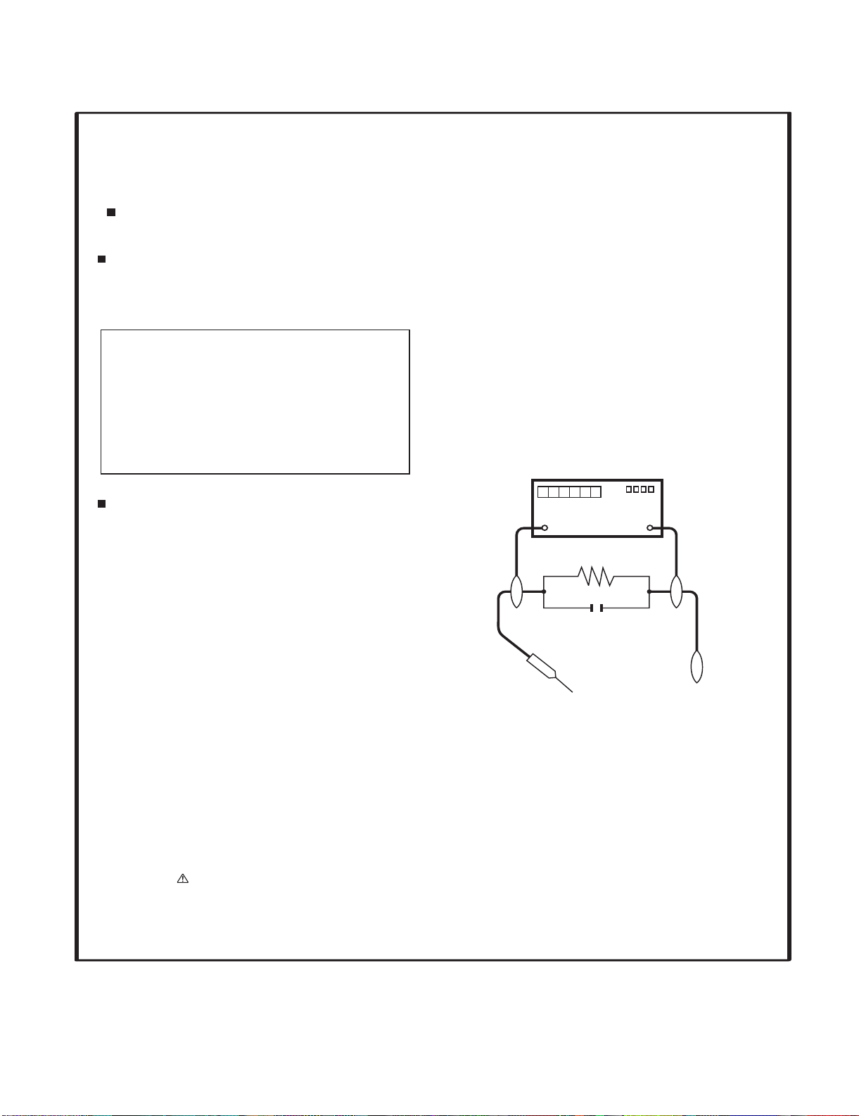
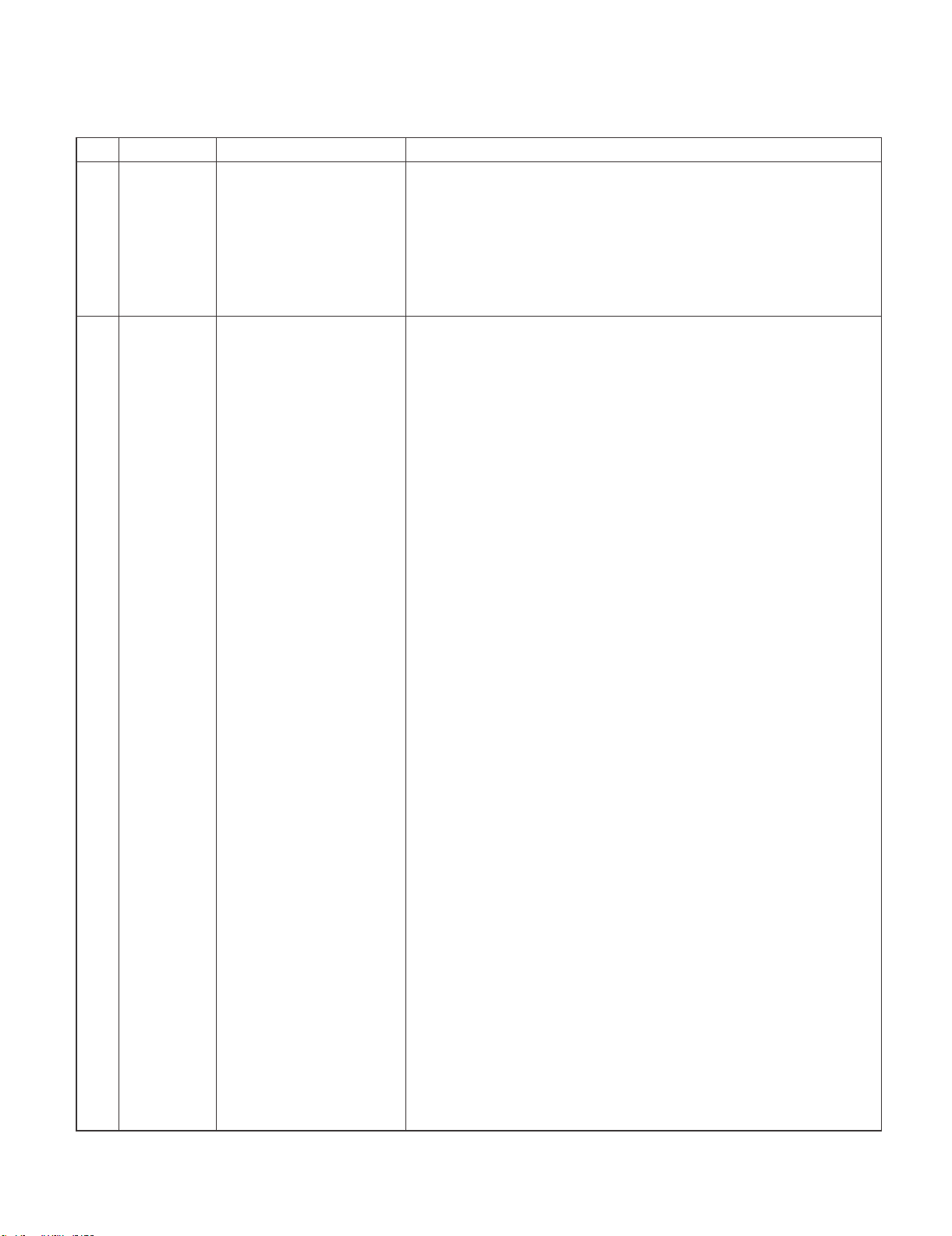
• Using two clip leads, connect a 1.5k ohm, 10 watt resistor paralleled by a 0.15PF capacitor in series with all exposed metal cabinet
parts and a known earth ground, such as electrical conduit or electrical ground connected to an earth ground.
• Use an AC voltmeter having with 5000 ohm per volt, or
sitivity or measure the AC voltage drop across the resistor.
• Connect the resistor connection to all exposed metal parts having a
return to the chassis (antenna, metal cabinet, screw heads, knobs
and control shafts, escutcheon, etc.) and measure the AC voltage
higher, sen-
drop across the resistor.
All checks must be repeated with the AC cord plug connection
reversed. (If necessary, a nonpolarized adaptor plug must be used
only for the purpose of completing these checks.)
Any reading of 0.75 Vrms (this corresponds to 0.5 mA rms AC.) or
more is excessive and indicates a potential shock hazard which
must be corrected before returning the monitor to the owner.
BEFORE RETURNING THE RECEIVER (Fire &
Shock Hazard)
Before returning the receiver to the user, perform the following
safety checks:
3. Inspect all lead dress to make certain that leads are not pinched,
DVM
AC SCALE
1.5k ohm
10W
and check that hardware is not lodged between the chassis and
other metal parts in the receiver.
4. Inspect all protective devices such as non-metallic control knobs,
insulation materials, cabinet backs, adjustment and compartment
covers or shields, isolation resistor-capacitor networks, mechanical
insulators, etc.
0.15µF
TEST PROBE
5. To be sure that no shock hazard exists, check for leakage current
in the following manner.
• Plug the AC cord directly into a 120 volt AC outlet.
TO EXPOSED
METAL PARTS
CONNECT TO
KNOWN EARTH
GROUND
///////////////////////////////////////////////////////////////////////////////////////////////////////////////////////////////////////////////////////////////////////////////////////////////////////////////////////////////////////////
SAFETY NOTICE
Many electrical and mechanical parts in LCD color television have
special safety-related characteristics.
These characteristics are often not evident from visual inspection, nor
can protection afforded by them be necessarily increased by using
replacement components rated for higher voltage, wattage, etc.
Replacement parts which have these special safety characteristics are
identified in this manual; electrical components having such features
are identified by " " and shaded areas in the Replacement Parts List
and Schematic Diagrams.
///////////////////////////////////////////////////////////////////////////////////////////////////////////////////////////////////////////////////////////////////////////////////////////////////////////////////////////////////////////
For continued protection, replacement parts must be identical to those
used in the original circuit.
The use of a substitute replacement parts which do not have the same
safety characteristics as the factory recommended replacement parts
shown in this service manual, may create shock, fire or other hazards.
i
Page 3
LC-60G9T / LC-70G9T
PRECAUTIONS FOR USING LEAD-FREE SOLDER
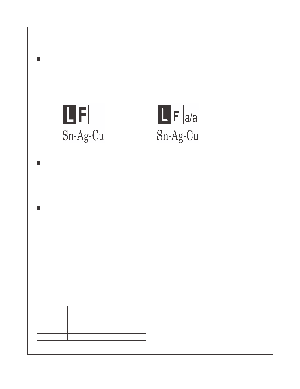
Employing lead-free solder
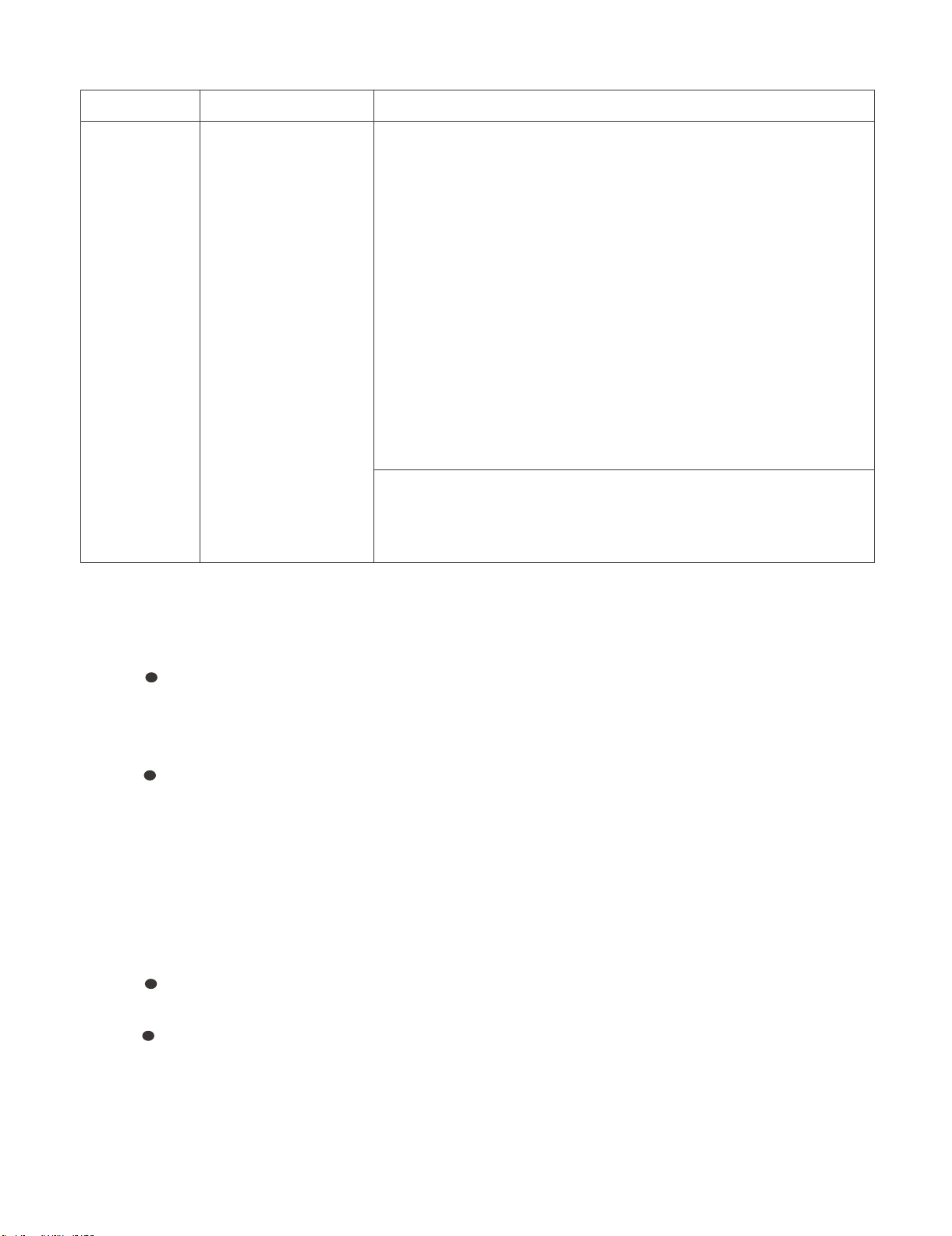
• “PWBs” of this model employs lead-free solder. The LF symbol indicates lead-free solder, and is attached on the PWBs and service manuals. The
alphabetical character following LF shows the type of lead-free solder.
Example:
Indicates lead-free solder of tin, silver and copper. Indicates lead-free solder of tin, silver and copper.
Using lead-free wire solder
• When fixing the PWB soldered with the lead-free solder, apply lead-free wire solder. Repairing with conventional lead wire solder may cause damage or accident due to cracks.
As the melting point of lead-free solder (Sn-Ag-Cu) is higher than the lead wire solder by 40 qC, we recommend you to use a dedicated soldering
bit, if you are not familiar with how to obtain lead-free wire solder or soldering bit, contact our service station or service branch in your area.
Soldering
• As the melting point of lead-free solder (Sn-Ag-Cu) is about 220 qC which is higher than the conventional lead solder by 40 qC, and as it has poor
solder wettability, you may be apt to keep the soldering bit in contact with the PWB for extended period of time. However, Since the land may be
peeled off or the maximum heat-resistance temperature of parts may be exceeded, remove the bit from the PWB as soon as you confirm the
steady soldering condition.
Lead-free solder contains more tin, and the end of the soldering bit may be easily corroded. Make sure to turn on and off the power of the bit as
required.
If a different type of solder stays on the tip of the soldering bit, it is alloyed with lead-free solder. Clean the bit after every use of it.
When the tip of the soldering bit is blackened during use, file it with steel wool or fine sandpaper.
• Be careful when replacing parts with polarity indication on the PWB silk.
Lead-free wire solder for servicing
PARTS CODE
ZHNDAi123250E BL J I0.3mm 250g (1roll)
ZHNDAi126500E BK J I0.6mm 500g (1roll)
ZHNDAi12801KE BM J I1.0mm 1kg (1roll)
PRICE
RANK
PART
DELIVERY
DESCRIPTION
ii
Page 4
LC-60G9T / LC-70G9T
OUTLINE
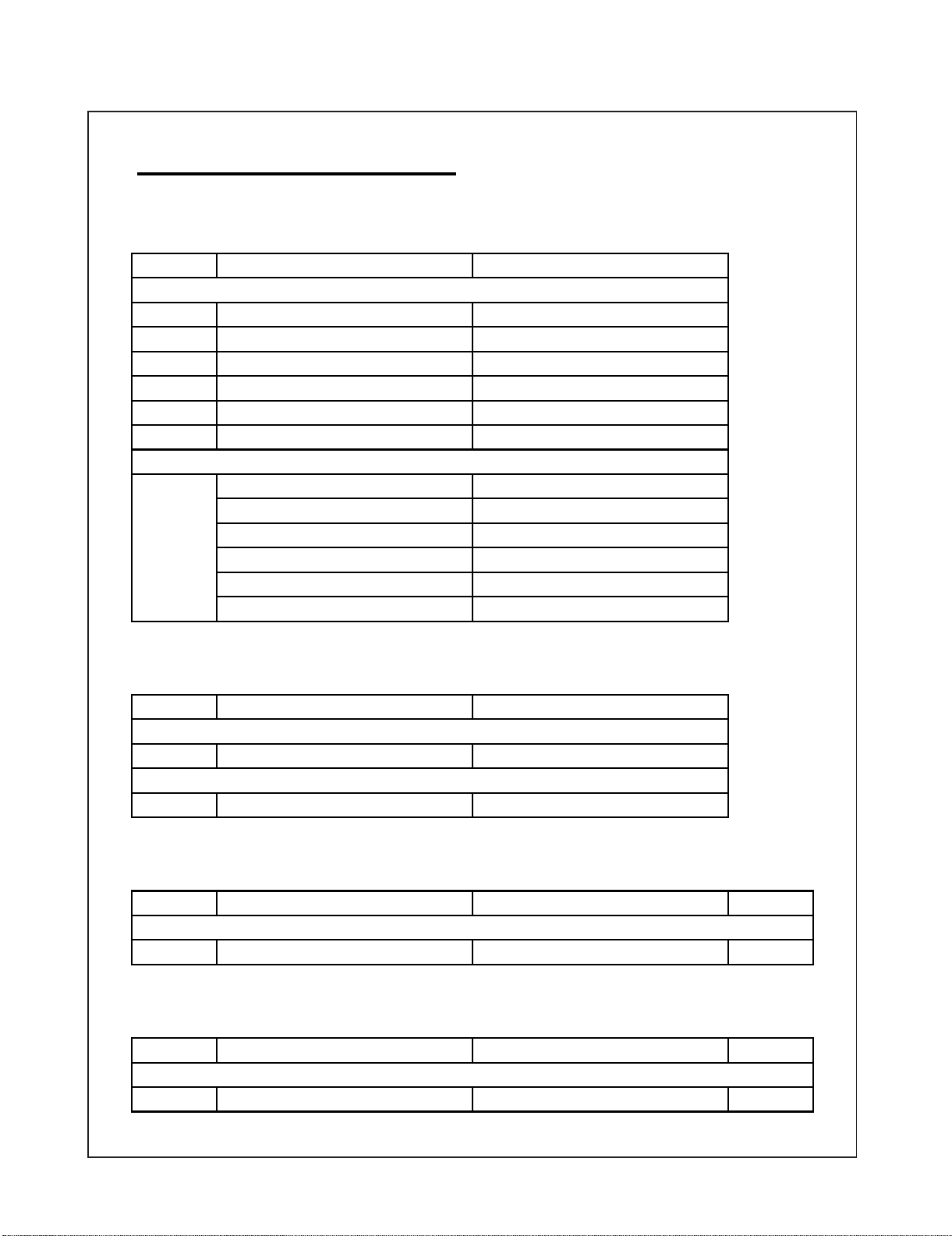
MAJOR SERVICE PARTS
PWB Unit
Ref NO.
LC-60G9T
DKEYFM216FMG3
RUNTKB116WJQZ
DUNTKG016FMG1
DUNTKF800FMF8
DUNTKG017FMF7
DUNTKG215FMG2
LC-70G9T
DKEYFM216FMG4
RUNTKB118WJQZ
DUNTKG016FMG1
DUNTKF800FMF8
DUNTKG017FMF7
DUNTKG215FMG2
OTHER unit
Ref NO.
LC-60G9T
R1JE600D3HD60W
LC-70G9T
R1JE695D3HB10W
PARTS CODE DESCRIPTION
tinUniaMN
tinurewoP06N
tinUCRDELN
tinUyeKN
tinUD3N
TN -Con Unit
tinUniaMN
tinurewoP07N
tinUCRDELN
tinUyeKN
tinUD3N
TN -Con Unit
PARTS CODE DESCRIPTION
06N -Inch Panel
07N -Inch Panel
IC For Exclusive Use of the Service
PARTS CODE DESCRIPTION
LC-60/70G9T
IC2004 RH-IXD515WJN8Q IC (Monitor Microprocessor) 1
Service Jigs
PARTS CODE DESCRIPTION
LC-60/70G9T
N QCNW-M539WJQZ
PD Main-Power + TCON 100cm
iii
YtQ.ONfeR
YtQ.ONfeR
1
Page 5
CHAPTER 1. SPECIFICATIONS
[1] SPECIFICATIONS
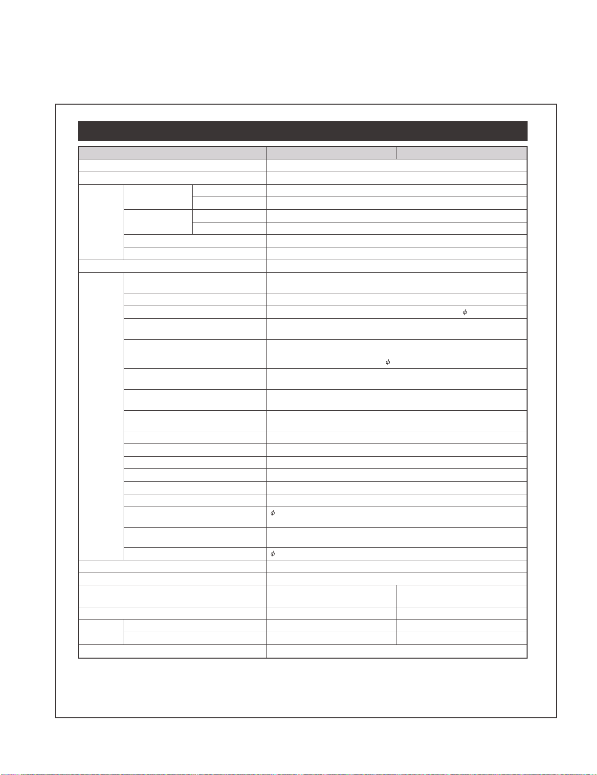
Specifications
LC-60G9T / LC-70G9T
Item
080,1x029,1noituloseR
06LAP/34.4CSTN/85.3CSTN/MACES/LAPmetsysruolocoediV
TV function TV-standard Analogue NTSC: M
Digital DVB - T
Receiving channel Analogue VHF/UHF 44.25-863.25 MHz
Digital VHF 470-806 MHz
hc531teserpotuAmetsysgninutVT
STEREO/BILINGUAL BTSC system
)refooW(1xW51,2xW01reifilpmaoiduA
Terminals
Power consumption (method IEC62087) 217 W
Operating temperature
*1
The HDMI 2 and 電腦(PC) terminals can both use the same audio input terminal.
• As a part of our policy of continuous improvement, SHARP reserves the right to make design and specification changes for product
improvement without prior notice. The performance specification figures indicated are nominal values of production units. There
may be some deviations from these values in individual units.
(無線電視/有線電視)
(Antenna input)
電腦
(PC) 15 pin mini D-sub, AUDIO in (shared usage with HDMI2) (
輸
入1 (INPUT 1) (ARC) HDMI HDMI (HDMI input) (480I, 576I, 480P, 576P, 720P/50Hz, 720P/60Hz,
輸
入2 (INPUT 2) HDMI HDMI (HDMI input) (480I, 576I, 480P, 576P, 720P/50Hz, 720P/60Hz,
輸
入3 (INPUT 3) HDMI HDMI (HDMI input) (480I, 576I, 480P, 576P, 720P/50Hz, 720P/60Hz,
輸
入 4 (MHL) HDMI HDMI (HDMI input) (480I, 576I, 480P, 576P, 720P/50Hz, 720P/60Hz,
輸
入 ,zH05/P027,P675,P084,I675,I084(niTNENOPMOC,niOIDUA)5TUPNI(5
輸
入 niOIDUA,niOEDIV)6TUPNI(6
輸
入 niOIDUA,niOEDIV)7TUPNI(7
USB 2 (無線網絡) (WIRELESS LAN) USB
(硬碟)
USB 3
乙太網絡ETHERNET (10/100 BASE-T) Network connector
聲音輸入(HDMI 2/電腦)
AUDIO IN (HDMI 2/PC)
數位聲音輸出
(DIGITAL AUDIO OUTPUT)
輸出(OUTPUT)/Headphones
ANT
(HDD) USB
UHF/VHF/CATV 75 q F type
1080I/50Hz, 1080I/60Hz, 1080P/50Hz, 1080P/60Hz, 1080P/24Hz)
1080I/50Hz, 1080I/60Hz, 1080P/50Hz, 1080P/60Hz, 1080P/24Hz),
AUDIO in (shared usage with PC) (
1080I/50Hz, 1080I/60Hz, 1080P/50Hz, 1080P/60Hz, 1080P/24Hz)
1080I/50Hz, 1080I/60Hz, 1080P/50Hz, 1080P/60Hz, 1080P/24Hz)
720P/60Hz, 1080I/50Hz, 1080I/60Hz)
3.5 mm jack*
Optical S/PDIF digital audio output
3.5 mm jack (audio output)
(0.3 W Standby)
0 °C to e 40 °C
rotcennocelamnip9buS-DC232-SR
3.5 mm jack)
BSU1BSU
1
esenihClanoitidarT/hsilgnEegaugnalDSO
zH06,V011CAtnemeriuqerrewoP
161 W
(0.3 W Standby)
W04W74edomrepapllawgnirudnoitpmusnocrewoP
gk93gk5.94dnatShtiWthgieW
gk23gk5.24dnatStuohtiW
T9G06-CLT9G07-CL
3.5 mm jack)
1 – 1
Page 6
LC-60G9T / LC-70G9T
CHAPTER 2. OPERATION MANUAL
[1] OPERATION MANUAL
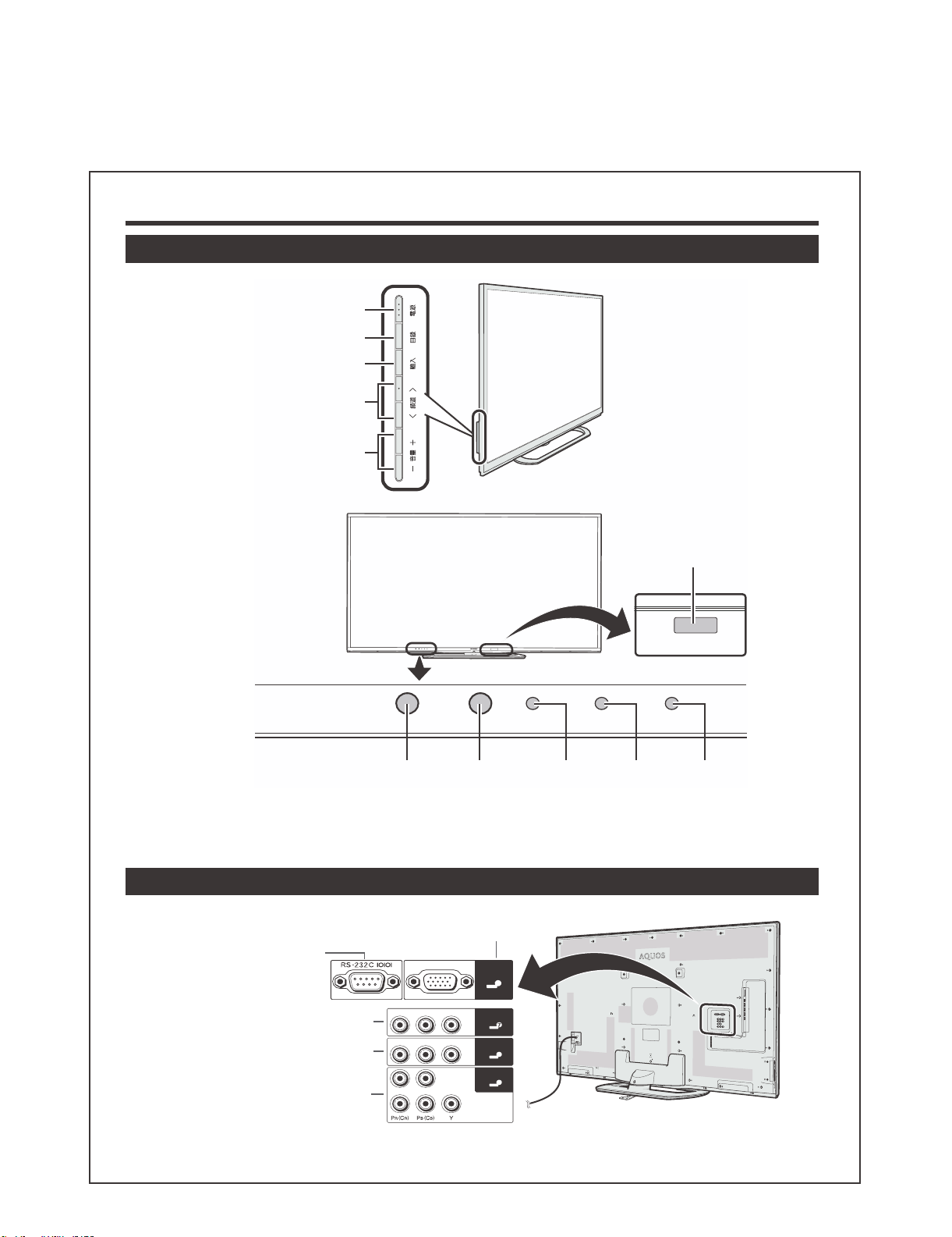
Part names and functions
TV (front view)
電源(POWER)
目錄(MENU)
輸入(INPUT)
頻道
r/s
(CH
音量
(VOL
r/s
e/f
e/f
)
)
REC
1
*
3Dinfraredemitter
POWER
Remotecontrol
sensor
*1
This panel emits infrared signal towards the 3D glasses you wear when viewing 3D images. Do not place anything between the 3D infrared emitter on
the TV and the infrared receiver on the 3D glasses.
*2
OPC: Optional Picture Control
OPC
sensor*
2
POWER
indicator
TIMER
TIMER
indicator
REC
indicator
TV (rear view)
電腦 (PC)terminal
RS-232Cterminal
電腦
8
輸入7( 影像 / 聲音 ( 左 / 右 ))
terminal(INPUT7)
輸入6( 影像 / 聲音 ( 左 / 右 ))
terminal(INPUT6)
輸入5( 色差端子 / 聲音 ( 左 / 右 ))
terminal(INPUT5)
右 聲音 左 影像
右 聲音 左 影像
右 聲音 左
色差端子
2 – 1
輸入7
輸入6
輸入5
6
5
Page 7
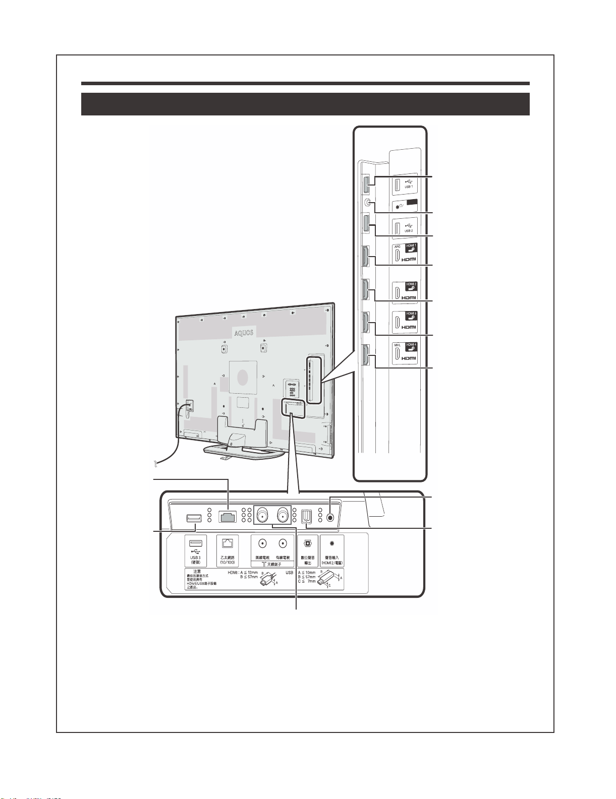
Part names and functions
TV (rear view) (continued)
USB1port
輸出
輸出(Headphones/
)右/左(音聲
聲音(左/右))
terminal
USB2port
(WIRELESSLAN)
HDMI1(HDMI/ARC)
terminal(INPUT1)
HDMI2(HDMI)
terminal(INPUT2)
LC-60G9T / LC-70G9T
*1
乙太網絡
(ETHERNET)
(10/100)terminal
USB3(硬碟)
(HDD)port
Antennaterminals(無線電視/有線電視)
(DC5V900mA)
HDMI3(HDMI)
terminal(INPUT3)
HDMI4(HDMI/MHL)
terminal(INPUT4)
聲音輸入(HDMI2/電腦)
(AUDIOIN(HDMI2/PC))
*2
jack
數位聲音輸出
(DIGITALAUDIO
OUTPUT)terminal
Regarding details of Skype, visit the following website.
skype: http://www.skype.com or Sharp: http://www.aquos-world.com
*1
The HDMI 2 and 電腦 terminals can both use the same audio input terminal(聲音輸入 (HDMI 2/電腦) (AUDIO IN) (HDMI 2/PC)). However, the proper
item must be selected in the “Audio select” menu .
WARNING
• Excessive sound pressure from earphones and headphones can cause hearing loss.
• Do not set the volume at a high level. Hearing experts advise against extended listening at high volume levels.
2 – 2
Page 8
LC-60G9T / LC-70G9T
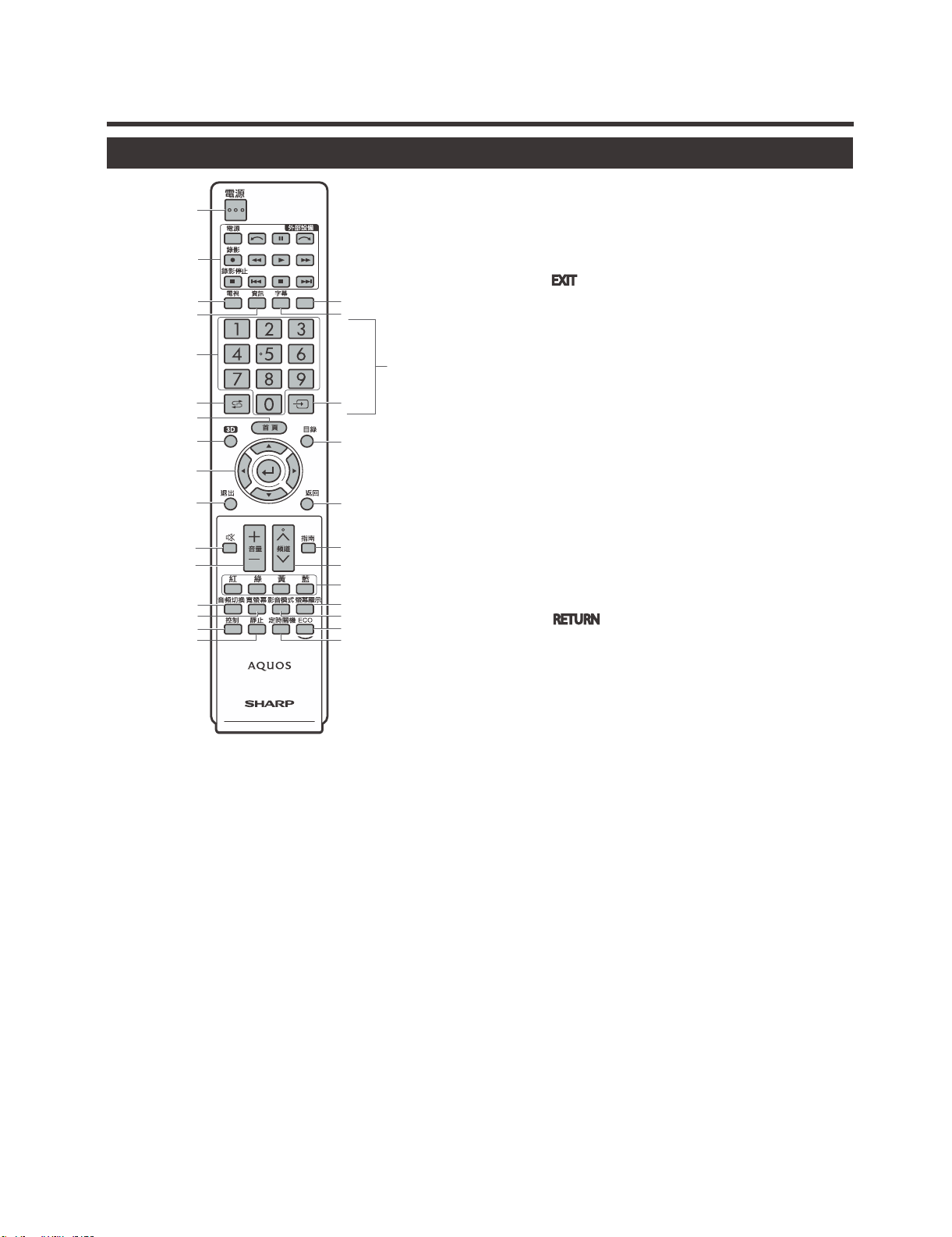
Part names and functions
Remote control unit
1
2
3
4
5
6
7
8
9
10
11
12
13
14
15
16
1 電源(<) (Standby/On)
To switch the power on and off .
2 外部設備 (EXT MEDIA) buttons
AQUOS LINK
If external equipment such as a AQUOS BD player
is connected via HDMI cables and is AQUOS LINK
compatible, you can use these EXT MEDIA buttons.
USB-recording
Record a programme you are watching.
3 電視 (>)
Press to access analogue and digital TV mode.
4 資訊(INFO)
DTV : Display the programme information .
ATV : Display the channel information.
50–9*
Set the channel .
6 A (Flashback)*
Press to return to the previously selected channel or
external input.
7 首頁 (HOME)
Display the “HOME” screen to enjoy Internet connection
and Home network function and to perform settings for the
TV .
**
17
18
19
20
21
22
23
24
25
26
27
83D
Select between 3D and 2D image viewing .
9 a/b/c/d (Cursor)
Select a desired item on the setting screen.
? (ENTER)
Execute a command.
10 退出( EXIT
Turn off the On-Screen Display .
11 e (Mute)
Mute the sound.
12 音
*
Set the volume.
13 音
頻切換 (MPX)
Select a sound multiplex mode .
14 寬螢幕 (WIDE)
Change a wide image mode .
15 控制 (CONTROL)
Press to display the panel to operate some functions on the
screen.
16 靜止 (FREEZE)
Freeze a motion picture on the screen.
17 字幕(Subtitle)
Switch subtitle languages on/off .
18 b (INPUT SOURCE)*
Select an input source .
19 目錄 (@)
Displays the menu screen .
20 返回 ( RETURN
Menu mode: Return to the previous menu screen .
21 指南(GUIDE)
DTV : To display EPG (Electronic Programme Guide) screen
ATV : Display the channel list.
22 頻道r/s (CHr/s)
TV input mode: Select the channel .
AQUOS.NET: Select the page .
23 紅/綠/黃/藍 (R/G/Y/B) (Colour) buttons
The coloured buttons are correspondingly used to select
the coloured items on the screen (e.g., AQUOS LINK, USB
media, Home network).
24 螢幕顯示 (DISPLAY)
Display the channel or input information.
Reveal/hide the guide display for USB media mode.
25 影音模式(#)
Select audio/video settings .
26 ECO
Select “Energy save” setting .
27 定時關機 (SLEEP)
Set the sleep timer.
+/‒
)
(Y+/‒)
)
NOTE
* “0 − 9”, “A”, “b” are used by string input like a mobile
phone.
** This button does not work on this model.
2 – 3
Page 9
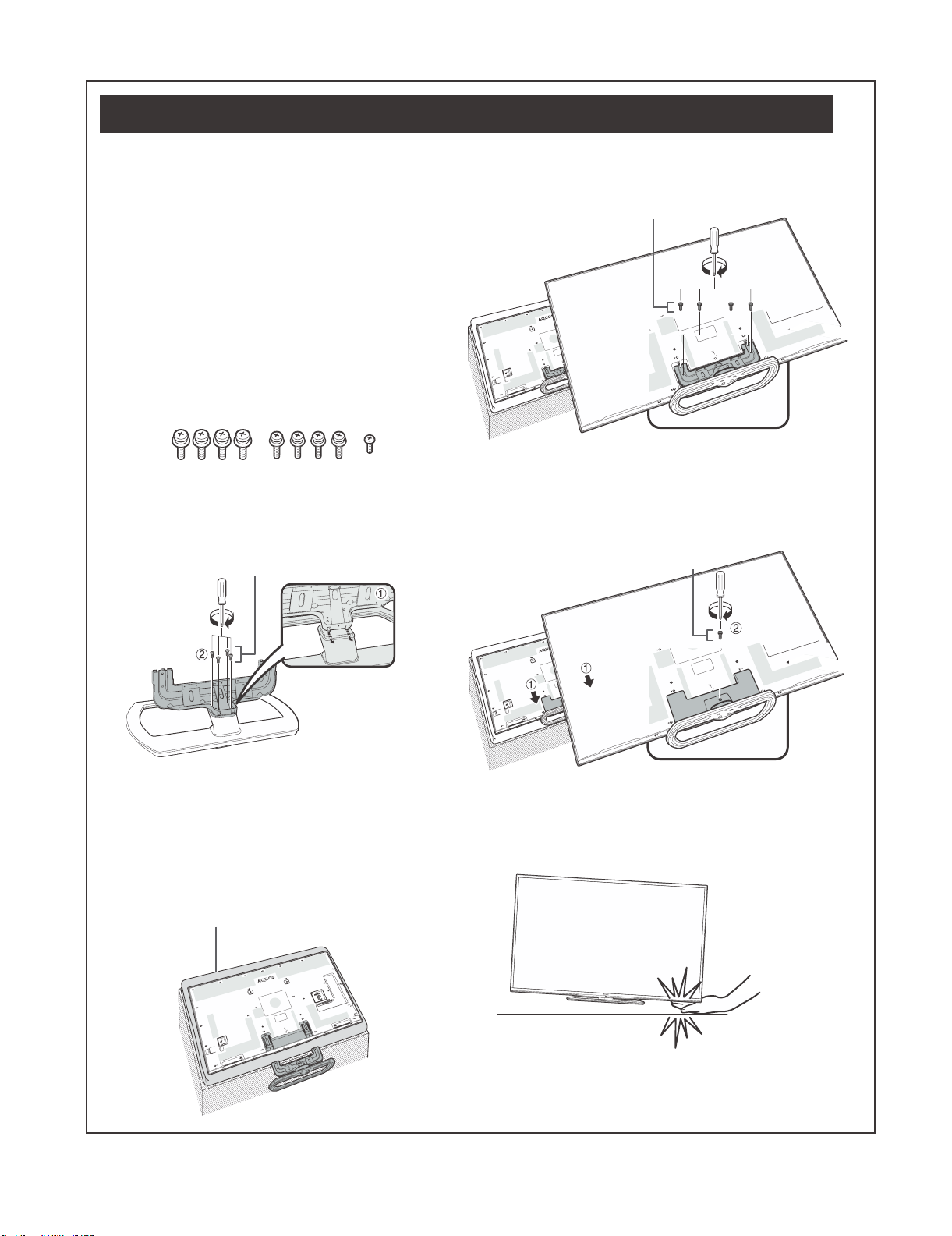
Attaching the stand unit
LC-60G9T / LC-70G9T
• Before attaching (or detaching) the stand, unplug the AC
cord.
• Before performing work, spread cushioning over the surface
on which you will be laying the TV. This will prevent it from
being damaged.
• Be sure that two or more persons attach the stand.
CAUTION
• Attach the stand in the correct direction.
• Be sure to follow the instructions. Incorrect installation
of the stand may result in the TV falling over.
• After attaching the stand to the TV, do not hold the
stand when you put up, set up, move or lay down the
TV.
• Do not remove the stand from the TV unless using a
wall mount bracket to mount it.
1
Confirmthatthereare9screws(fourM6screws,
fourM5screwsandoneM4screw)suppliedwith
thestandunit.
2
Attachthesupportingposttothestandbase.
1
Insert the claws of the supporting post into the stand
base.
2
Secure the post and the base using the M6 screws
(length: 60" (10 mm / 70" (20 mm)) and a screwdriver.
M6 screws
4
InsertandtightentheM5screws(length:14mm)
intotheholesontherearoftheTV.
M5 screws
5
Attachingthestandcover.
1
Insert the stand cover.
2
Insert and tighten the M4 screw (length: 8 mm) into the
holes of the stand cover.
• Tighten the screw by pressing the bottom of the
stand base to the TV side.
M4 screw
NOTE
• Tighten the screws to the holes of the mark “b”.
3
Insertthestandintotheopeningsonthebottom
oftheTV(holdthestandsoitwillnotdropfrom
theedgeofthebasearea).
• Make sure that the stand is firmly inserted into the TV.
Improper installation may result in tilting of the TV set.
Soft cushion
NOTE
• To detach the stand unit, perform the steps in reverse order.
• A screwdriver is not supplied with this product.
• In the installation procedure, be careful not to catch your
fingers between the TV set and the floor.
2 – 4
Page 10
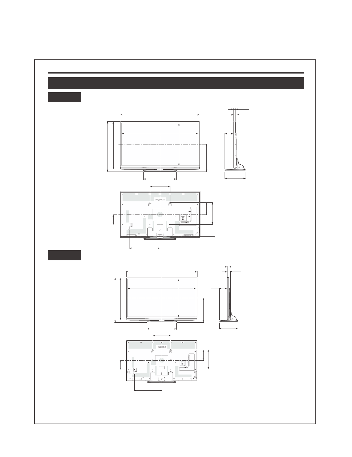
CHAPTER 3. DIMENSIONS
[1] DIMENSIONS
Dimensional drawings
LC-70G9T
(971)
(932)
(1539)
LC-60G9T / LC-70G9T
*2
(28)
(1578)
*1
*1
(866)
(178)
(513)
(58)
LC-60G9T
(251)
(848)
(810)
(1329)
(621)
*1
(640)
(400)
(1378)
(640)
(400)
*1
(748)
(451)
(200)
(400)
(178)
(385)
(385)
(28)
(58)
*2
(176)
*1
Active area
*2
Thinnest part (except of terminal height)
(575)
NOTE
• Dimensions do not include protrusions such as screws and some parts.
3 – 1
(200)
(400)
Page 11
LC-60G9T / LC-70G9T
CHAPTER 4. REMOVING OF MAJOR
PARTS
R
E
M
O
V
I
N
G
O
F
M
A
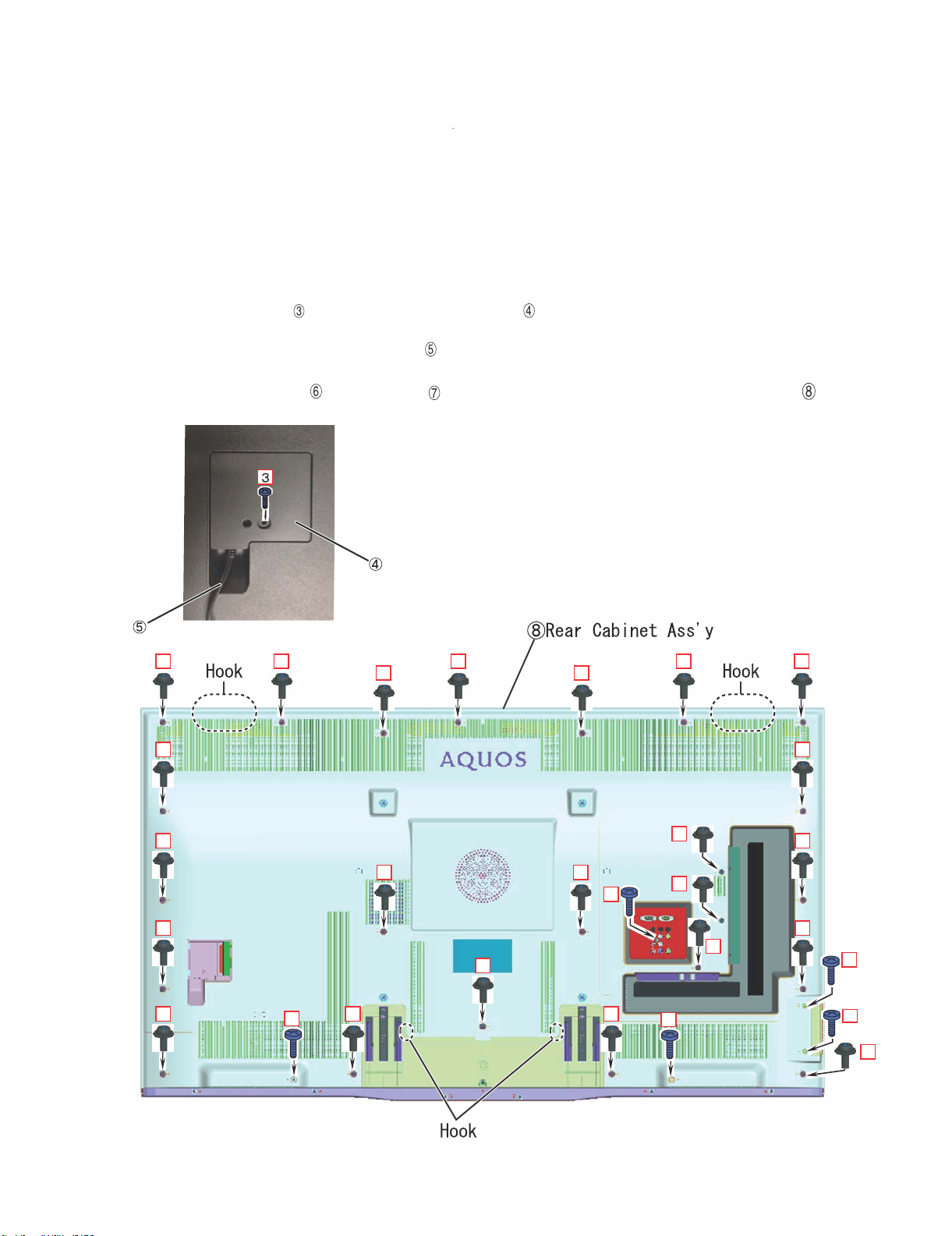
1. Removing of Stand Unit and Rear Cabinet Ass'y. (LC-60G9T/ LC-70G9T)
1. Remove the 1 lock screw and detach the Stand Safety Cover Ass'y.
2. Remove the 4 lock screws and detach the Stand Unit.
3. Remove the 1 lock screw and detach the AC Cord Cover .
4. Disconnect AC Wire and detach the AC Cord .
5. Remove the 23 lock screws , 5 lock screws and the 4 Hooks and detach the Rear Cabinet Ass'y .
AC Cord Cover
AC Cord
J
O
R
P
A
R
T
R
E
M
O
V
I
N
G
O
F
M
A
J
O
R
P
A
R
T
R
E
M
O
V
I
N
G
O
F
M
A
J
O
R
P
A
R
T
R
E
M
O
V
I
N
G
O
F
M
A
J
O
R
P
A
R
T
R
E
M
O
V
I
N
G
O
F
M
A
J
O
R
P
A
R
T
4 – 1
Page 12
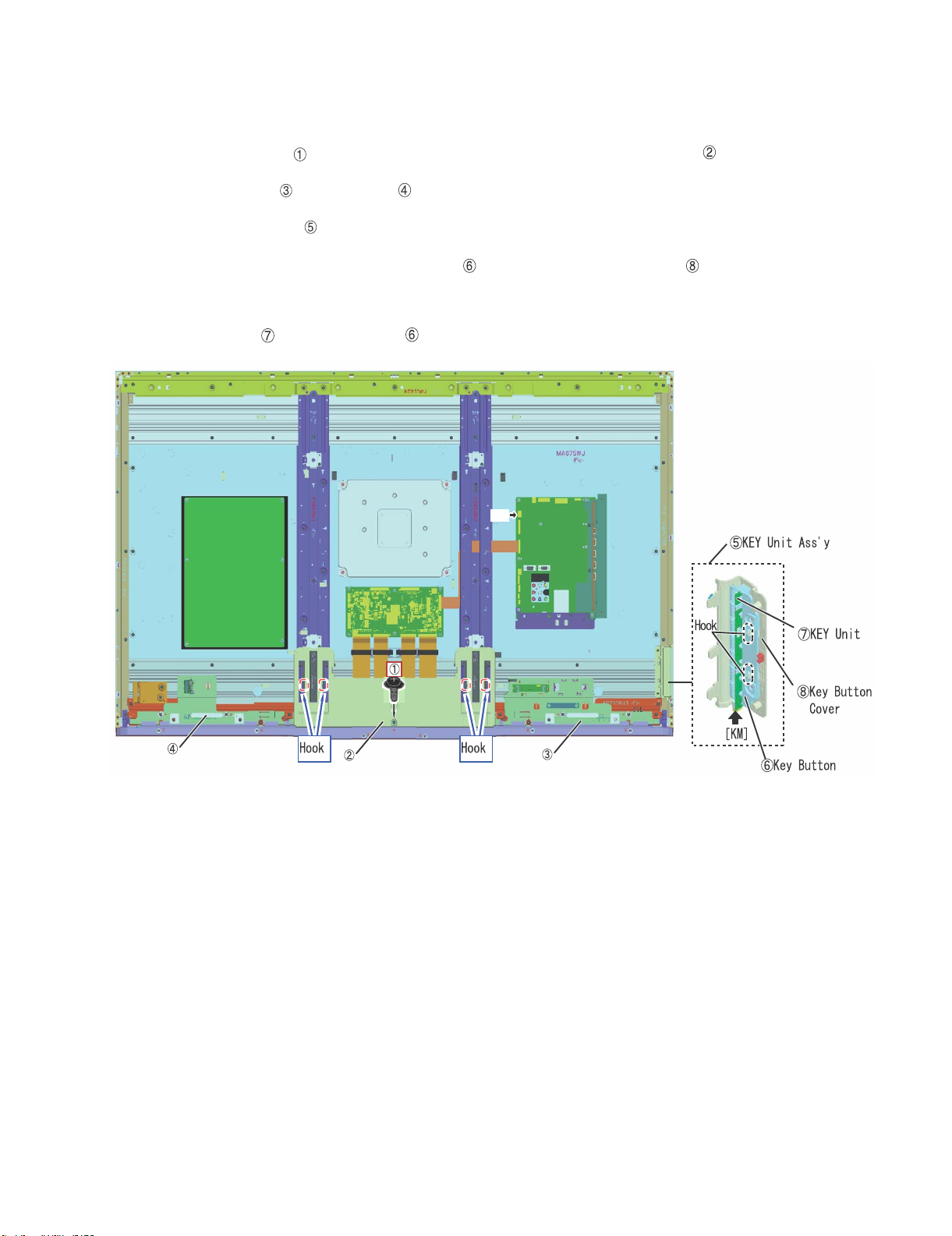
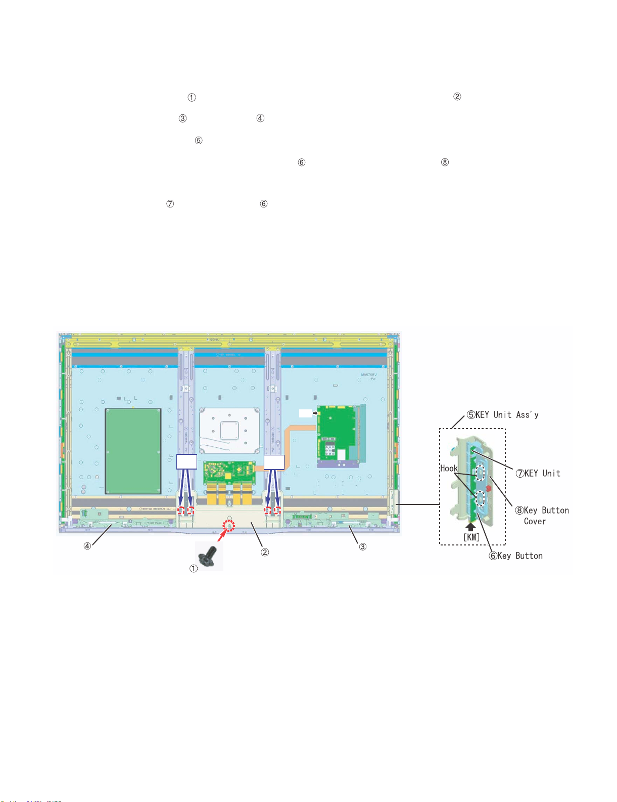
2. Removing of Speaker (L/R) and KEY Unit. ( LC-60G9T )
1. Remove the 1 lock screw and the 4 Hooks and detach the Bottom Cover Ass’y .
2. Detach the Speaker (L) , Speaker (R) .
3. Detach the KEY Unit Ass'y .
4. Remove the 2 Hooks and detach the Key Button from the Key Button Cover .
5. Disconnect the KM wire.
6. Detach the KEY Unit from Key Button .
LC-60G9T / LC-70G9T
Speaker (R)
Bottom Cover Ass'y
SP
Speaker (L)
4 – 2
Page 13

LC-60G9T / LC-70G9T
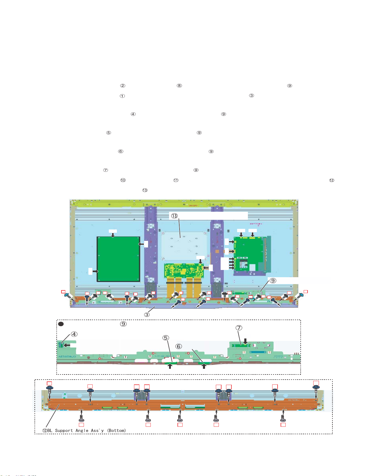
3. Removeing of Connectors and Decoration Cover, Front Cover Ass'y and Back Light Support Angle Bottom
Ass'y. ( LC-60G9T )
1. Disconnect the following connectors from MAIN Unit. (SB,PD,LV)
2. Disconnect the following connectors from POWER/DRIVE Unit. (L1,PD)
3. Disconnect the following connectors from LCD CONTROL Unit. (PL,LV)
4. Remove the 2 lock screws , 10 lock screws and detach the Front Cover Ass'y .
5. Remove the 6 lock screws and detach the Decoration Cover (Rear) .
6. Disconnect the following connector from BLUETOOTH Unit. (BT)
7. Detach the BLUETOOTH Unit from the Front Cover Ass'y .
8. Disconnect the following connector from ICON Unit. (CI)
9. Detach the ICON Unit from the Front Cover Ass'y .
10.Disconnect the following connector from R/C OPC Unit. (RA)
11.Detach the R/C OPC Unit from the Front Cover Ass'y .
12.Disconnect the following connector from WiFi Unit. (UB)
13.Detach the WiFi Unit from the Front Cover Ass'y .
14.Remove the 8 lock screws , 5 lock screws and detach the BL Support Angle Ass'y (Bottom) .
15.Detach the Speaker Unit (Woofer) .
2
Front Cover Ass'y
BLUETOOTH UNIT
BT
10
Speaker Unit (Woofer)
L1
PD
LV SP
PL
AC
8 8 8 8 8 8 8
11
8
1
RC
BT
LV
IR
UB
1
Decoration Cover (Rear)
PDSB
8 8
1
1
WiFi UNIT
ICON UNIT
UB
R/C OPC UNIT
CI RA
10
1010
10 10
Front Cover Ass'y
2
10
10
11
11
11
11
11
4 – 3
Page 14
LC-60G9T / LC-70G9T
2. Removing of Bottom cover, Speaker(L/R), KEY Unit Ass'y.( LC-70G9T )
1. Remove the 1 lock screw and the 4 Hooks and detach the Bottom Cover Ass’y .
2. Detach the Speaker (L) , Speaker (R) .
3. Detach the KEY Unit Ass'y .
4. Remove the 2 Hooks and detach the Key Button from the Key Button Cover .
5. Disconnect the KM wire.
6. Detach the KEY Unit from Key Button .
Speaker (R)
Hook Hook
Bottom Cover Ass'y
SP
Speaker (L)
4 – 4
Page 15
LC-60G9T / LC-70G9T
3. Removeing of Connectors and Decoration Cover, Front Cover Ass'y and Back Light Support Angle Bottom
Ass'y. ( LC-60G9T )
1. Disconnect the following connectors from MAIN Unit. (SB,PD,LV)
2. Disconnect the following connectors from POWER/DRIVE Unit. (L1,PD)
3. Disconnect the following connectors from LCD CONTROL Unit. (PL,LV)
4. Remove the 2 lock screws , 10 lock screws and detach the Front Cover Ass'y .
5. Remove the 6 lock screws and detach the Decoration Cover (Rear) .
6. Disconnect the following connector from BLUETOOTH Unit. (BT)
7. Detach the BLUETOOTH Unit from the Front Cover Ass'y .
8. Disconnect the following connector from ICON Unit. (CI)
9. Detach the ICON Unit from the Front Cover Ass'y .
10.Disconnect the following connector from R/C OPC Unit. (RA)
11.Detach the R/C OPC Unit from the Front Cover Ass'y .
12.Disconnect the following connector from WiFi Unit. (UB)
13.Detach the WiFi Unit from the Front Cover Ass'y .
14.Remove the 8 lock screws , 5 lock screws and detach the BL Support Angle Ass'y (Bottom) .
15.Detach the Speaker Unit (Woofer) .
2
Front Cover Ass'y
BLUETOOTH UNIT
BT
10
Speaker Unit (Woofer)
L1
PD
LV SP
PL
AC
8 8 8 8 8 8 8
11
8
1
RC
BT
LV
IR
UB
1
Decoration Cover (Rear)
PDSB
8 8
1
1
WiFi UNIT
ICON UNIT
UB
R/C OPC UNIT
CI RA
10
1010
10 10
Front Cover Ass'y
2
10
10
11
11
11
11
11
4 – 5
Page 16

LC-60G9T / LC-70G9T
CHAPTER 5. ADJUSTMENT
[1] ADJUSTMENT
[1] ADJUSTMENT PROCEDURE
Main unit supplied as service unit was adjusted on some item.
However, W/B adj is not finished because it needs to be done by final set condition. So the main unit is in the adjustment condition when it is supplied
and K mark is shown up in display when you use it. After finishing Factory setting, K -mark disappear so please do it as following ADJUSTMENT
PROCUDURE.
The adjustment values are set to the optimum conditions at the factory before shipping. If a value should become improper or an adjustment is
required due to part replacement, make an adjustment according to the following procedure.
1. After replacement of any PWB unit and/or IC for repair, please note the following.
x When replacing the following units, make sure to prepare the new units loaded with updated software.
MAIN Unit: DKEYMF216FMG3: LC-60G9T
DKEYMF216FMG4: LC-70G9T
x When replacing the LCD control PWB, perform the VCOM adjustment.
2. Upgrading of each microprocessor software
CAUTION: Never “POWER OFF” the unit when software upgrade is ongoing.
Otherwise the system may be damaged beyond recovery.
2.1. Software version upgrade
The model employs the following software.
• Main software LC-60/70G9T (please use a software version after XIAN_G9T_XXX.USB)
• Monitor microprocessor software (please use a software version XIANSUBXXX-SMB)
The main software, monitor microprocessor software can be upgraded by using a general-purpose USB Memory.
The followings are the procedures for upgrading, explained separately for the main software, monitor microprocessor software.
2.2. Main software version upgrade
2.2.1 Get ready before you start
• USB Memory of 128MB or higher capacity.
• PC running on Windows 98/98SE/ME/2000/XP operating system.
• USB Memory reader/writer or PC with a USB port.
• The file system of a USB memory is FAT. (FAT32 supports)
• Use the USB memory without other functions. (lock and memory reader...etc)
2.2.2 Preparations
To upgrade the main software, it is necessary to get ready the USB Memory for version upgrade before you start.
Follow the steps below and create the USB Memory for version upgrade.
1. Copy the file XIAN_G9T-XXX.USB for version upgrade to the root directory (folder) of the USB Memory.
NOTE: In the USB Memory drive, do not store other folders or unrelated files, or more than one file for version upgrade.
Now the USB Memory for version upgrade is ready.
5 – 1
Page 17

LC-60G9T / LC-70G9T
2.2.3 How to upgrade the software
1. Unplug the AC cord.
2. Insert the USB Memory for version upgrade into USB1.
3. Plug in the AC cord with power button pressed down.
4. After 5 seconds, unpress the power button.
5. After the unit startup, the system upgrade screen as shown below within 20-40 seconds.
Software Update
MAIN
SUB MICOM
PANEL EEPROM
3D IR MICOM
MAIN Version
SUB MICOM Version
PANEL EEPROM
3D IR MICOM Version
6. Even a single failure in the process will trigger the upgrade failure screen.
Software Update
UPGRADE FAILURE
MAIN
SUB MICOM
PANEL EEPROM
3D IR MICOM
MAIN Version
SUB MICOM Version
PANEL EEPROM
3D IR MICOM Version
60/70G9T
26%
NO DATA
NO DATA
095X1307021
60/70G9T
Project ID
NO DATA
NO DATA
NOTE: In the event of a failure, repeat the upgrade process. If the process repeatedly fails, it is likely that the hardware need fixing.
7. Upon completion of the whole process, the upgrade success screen as shown below appears. You can check the new software version on this
screen. The version information appears after the upgrade is complete.
Software Update
MAIN Version
SUB MICOM Version
PANEL EEPROM
3D IR MICOM Version
UPGRADE SUCCESS
MAIN
SUB MICOM
PANEL EEPROM
3D IR MICOM
100%
NO DATA
NO DATA
095X1307021
60/70G9T
8. Unplug the AC cord and remove the USB Memory for version upgrade.
9. Now the software version upgrade is complete.
NOTE: When you are done with the software version upgrade, start the set, go to the top page of the adjustment process screen and check the main
software version information.
If you upgrade the software version of 60/70G9T the model name is upgrade screen is displayed as 60/70G9T.
5 – 2
Page 18

LC-60G9T / LC-70G9T
2.3. Monitor microprocessor software version upgrade
Create the USB memory for monitor microprocessor software version upgrade in the same manner as explained in the “Main software version
upgrade”.
Copy the file XIAN_G9T_XXX.USB and XIANSUBxxx.SMB. (named temporarily) for monitor microprocessor software version upgrade to the
USB memory.
2.3.1 How to upgrade the software
1. Unplug the AC cord.
2. Insert the USB Memory for version upgrade into USB1.
3. Plug in the AC cord with power button pressed down.
4. After 5 seconds, unpress the power button.
CAUTION: • The moment this operation is done, the upgrading of the monitor microprocessor software starts. While the upgrade is ongoing, never
5. After the unit startup, the upgrade starts. The power led will blink co
power off the unit. Otherwise the upgrade will fail and the system may be serious damaged beyond recovery (inability to start).
• After the monitor microprocessor software is upgraded, also perform the 'Industry Init'.
ntinuously. Also, an upgrade screen will be shown during a minor upgrade.
Software Update
MAIN Version
SUB MICOM Version
PANEL EEPROM
3D IR MICOM Version
MAIN
SUB MICOM
PANEL EEPROM
3D IR MICOM
NO DATA
50%
NO DATA
0.820
60/70G9T
6. If the upgrade fails, power led will stop blinking. Also, the upgrade failure screen will be shown if upgrade screen was shown at 5.
Software Update
MAIN Version
SUB MICOM Version
PANEL EEPROM
3D IR MICOM Version
UPGRADE FAILURE
MAIN
SUB MICOM
PANEL EEPROM
3D IR MICOM
NO DATA
SAME VERSION
NO DATA
60/70G9T
NOTE: In the event of a transient failure, upgrade will be automatically retried up to three times. If the process repeatedly fails, hardware may be the
cause.
7. The upgrade success screen will be shown if upgrade screen was shown at 5.
Software Update
MAIN Version
SUB MICOM Version
PANEL EEPROM
3D IR MICOM Version
UPGRADE SUCCESS
MAIN
SUB MICOM
PANEL EEPROM
3D IR MICOM
NO DATA
100%
NO DATA
0.820
60/70G9T
8. Unplug the AC cord and remove the USB Memory for version upgrade.
9. Now the software version upgrade is complete.
NOTE: When you are done with the software version upgrade, start the set, go to the top page of the adjustment process screen and check the mon-
itor microprocessor software version information and panel size information.
If you upgrade the software version of 60/70G9T, the model name in upgrade screen is displayed as 60/70G9T.
5 – 3
Page 19
LC-60G9T / LC-70G9T
3. Entering and exiting the adjustment process mode
1) Before entering the adjustment process mode, the AV position RESET in the video adjustment menu.
2) While holding down the “VOL(-)” and “INPUT” keys at a time, plug in the AC cord of the main unit to turn on the power.
The letter “<K>” appears on the screen.
3) Next, hold down the “VOL(-)” and “CH( )” keys at a time.
(The “VOL (—)” and “CH ( )” keys should be pressed and held until the display appears.)
Multiple lines of blue characters appearing on the display indicate that the unit is now in the adjustment process mode.
When you fail to enter the adjustment process mode (the display is the same as normal startup), retry the procedure.
4) To exit the adjustment process mode after the adjustment is done, unplug the AC cord from the outlet to make a forced shutdown. (When the
power was turned off with the remote controller, once unplug the AC cord and plug it again. In this case, wait 10 seconds or so before plugging.)
CAUTION: Use due care in handling the information described here lest your users should know how to enter the adjustment process mode. If the
4. Remote controller key operation and description of display in adjustment process mode
1) Key operation
CH ( / )
VOL (+/–) VOL (+/–) Changing a selected item setting (+1/ –1)
Cursor (UP/DOWN) ————— Turing a page (PREVIOUS/NEXT)
Cursor (LEFT/RIGHT) ————— Changing a selected line setting (+10/ –10)
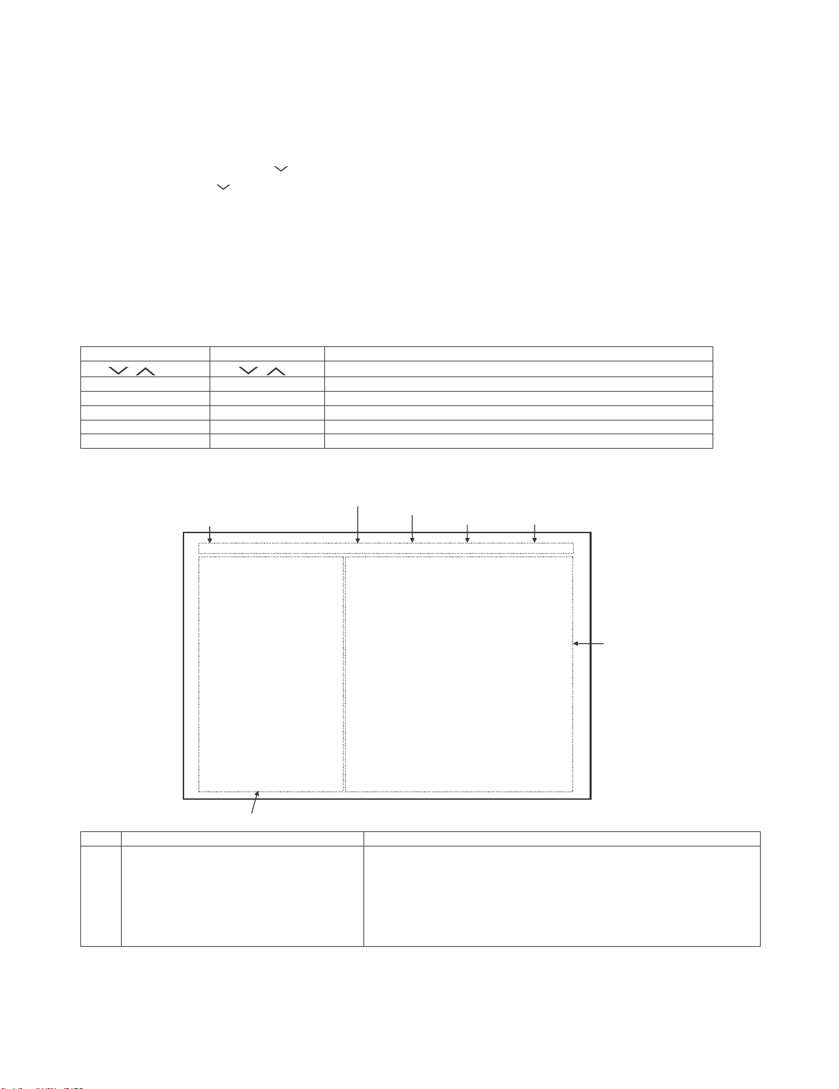
2) Description of display
settings are tampered in this mode, unrecoverable system damage may result.
noitcnuFyektinuniaMyekrellortnocetomeR
CH ( / )
Moving an item (line) by one (UP/DOWN)
)gnihctiwselggot(gnihctiwstupnI—————TUPNI
noitcnufagnitucexE—————RETNE
*Input mode is switched automatically when relevant adjustment is started so far as the necessary input signal is available.
(1) Current page/
Total pages
(2) Current selected input
(3) Current color system
(4) Inducing display
(5) LCD Panel size/Speaker type
MAIN Version
BOOT Version
Monitor Version
T-CON Version / LED CON Version
NET TV KEY / MAC
CI+INFO/SECURE BOOT
MARLIN
FRC Version
VMDRM
LAMP ERROR
MONITOR ERR CAUSE
NORMAL STANDBY CAUSE
ERROR STANDBY CAUSE
(6) Item name
AILARTSUAOTUAVTD02/1
1.00 (X 2012/XX/XX)
PRAHA 100
1.00
XXXXXXX / XX
----/XX-XX-XX-XX-XX-XX
----/No
0
1) XXXXX 2) XXXXX
3) XXXXX 4) XXXXX
0
00000
G9T
(7) Parameters
noitacificepsyalpsiDnoitpircseD.oN
(1) Present page/number of total pages 2char/2char Decimal Number mark.
(2) Input that has been selected now DTV/TUNER/INPUT1/INPUT2/INPUT3/INPUT4/INPUT5/INPUT6/INPUT7
.cte05/i0801/i085/i084/MACES/LAP/344N/853N/OTUAmetsysruoloctneserP)3(
LARENEG/DNALAEZWEN/AILARTSUAyalpsidgnicudnI)4(
(5) Inch setting and Model name display Inch setting and Model name display
rahc03.xaMemanmetI)6(
rahc06.xaMretemaraP)7(
NOTE: In the case of 60G9T or 70G9T also ,the model name of ( 5 ) is displayed as G9T.
.
5 – 4
Page 20
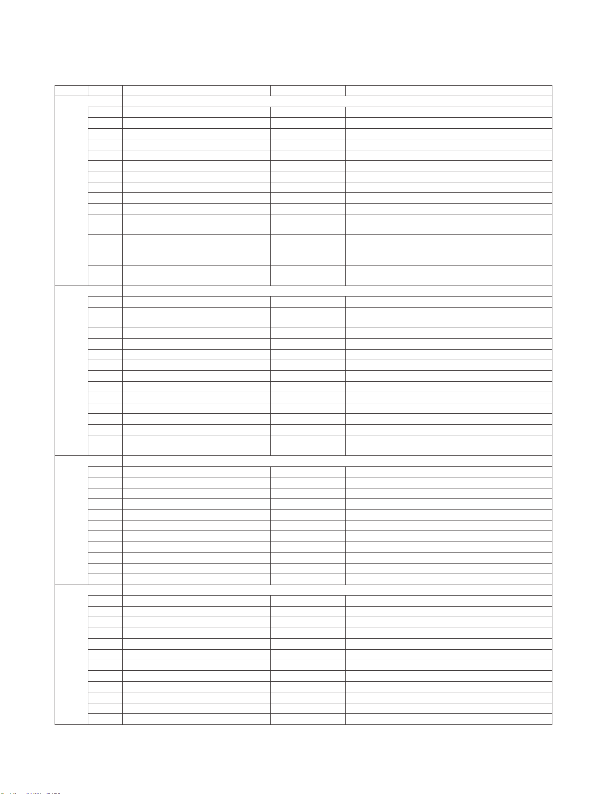
5. List of adjustment process mode menu
The character string in brackets [ ] will appear as a page title in the adjustment process menu header.
1/20
4 T-CON Version / LED CON Version xxxxxxxx/xxxx T-CON/H.264 Version
6 CI + INFO / SECURE BOOT xxxxx/NO CI + Key Information / SECURE BOOT
7 MARLIN
8 FRC Version
9 IR Micom Version
2/20
3/20
4/20
11 MONITOR ERR CAUSE 1) xxxxxx 2) xxxxxx
4
7 TUNER ADJ (SMPTE CH57) Enter TUNER auto adjustment execution (SMPTE CH57)
8 PAL+TUNER ADJ (SMPT
10 TUNER CONTRAST D_GAIN 2048 TUNER signal level adjustment
11 TUNER CONTRAST OFFSET 256 TUNER signal level adjustment
8 SECAM CONTRAST D_GAIN 2048 SECAM contra
9 SECAM CONTRAST OFFSET 256 SECAM contrast adjustment
E CH57) Enter PAL TUNER auto adjustment execution (SMPTE CH57)
3) xxxxxx 4) xxxxxx
Last error standby cause.
(Excluding the error) Refer to 7. STANDBY CAUSE FUNCTIONS.
TIONS.
itazilaitinIretnETINIYRTSUDNI1 on to factory settings execution.
ilaitinIFFO)cilbuP-(TINIYRTSUDNI2 zation to factory settings execution.
(Public mode is excluded)
(Level appears in green on the upper right)
noisreverawtfosniaM)xxxxx(xxx1noisreVNIAM1
noisreVTOOBxxxxxxxnoisreVTOOB2
sserddACAMxxxx/xxxCAM/YEKVTTEN5
.sruohgnitareponiaM—emitucAretneC
.teserrorrepmaLFFOTESERRORREPMAL8
TESMARAPJDAretnETESMARAPJDA9
tnemtsujdaLAPretnEJDALAP1
tnemtsujdaMACESretnEJDAMACES2
tnemtsujda853NretnEJDA853N3
st adjustment
LC-60G9T / LC-70G9T
noisreverawtfosrotinoMxxxxxxxnoisreVrotinoM3
.rorrepmaloteudnoitanimretforebmuN0RORREPMAL01
.dneehttaybdnatsemacebtahtnoitasutiS0ESUACYBDNATSLAMRON21
gnittesFFO/NOedomcilbuPFFOEDOMCILBUP3
.tesersruohgnitareponiaMFFOTESER5
.sruohgnitarepothgilkcaB—emitucAthgilkcaB6
.tesersruohgnitarepothgilkcaBFFOTESER7
DAERCIVrofgnittesetanidrooc-X0SOPXCIV01
DAERCIVrofgnittesetanidrooc-Y0SOPYCIV11
DAERCIVrofgnittesepytlangiSNIAMEPYTLANGISCIV21
noitcnufnoitisiuqcalevelerutciPFFODAERCIV31
cexetnemtsujdaotuaRENUTretnEJDARENUT1
noitu
noitucexetnemtsujdaotuaRENUTLAPretnEJDARENUT+LAP2
)HC8-AC(noitucexetnemtsujdaotuaRENUTretnE)HC8-AC(JDARENUT3
)ETPMS(noitucexetnemtsujdaotuaRENUTretnE)ETPMS(JDARENUT5
tnemtsujdalevellangisRENUT41NIAG_ATSARTNOCRENUT9
tnemtsujdatsartnocLAP41NIAG_ATSARTNOCLAP4
tnemtsujdatsartnocLAP8402NIAG_DTSARTNOCLAP5
tnemtsujdatsartnocLAP652TESFFOTSARTNOCLAP6
tnemtsujdatsartnocMACES41NIAG_ATSARTNOCMACES7
tnemtsujdatsartnoc853N41NIAG_ATSARTNOC853N01
tnemtsujdatsartnoc853N8402NIAG_DTSARTNOC853N11
tnemtsujdatsartnoc853N652TESFFOTSARTNOC853N21
).cte,liatedtnemtsujda(skrameRnoitpircseDmetIeniLegaP
-CNUFESUACYBDNATS.7otrefeR.esuacybdnatsrorrE0000ESUACYBDNATSRORRE31
)HC8-AC(noitucexetnemtsujdaotuaRENUTLAPretnE)HC8-AC(JDARENUT+LAP4
)ETPMS(noitucexetnemtsujdaotuaRENUTLAPretnE)ETPMS(JDARENUT+LAP6
5 – 5
Page 21
LC-60G9T / LC-70G9T
5/20
3 INSPECT USB TERM PORT ALL : - - - - - - Reading inspection of USB memory terminal
4 MONIDATA READ [TEMP/OPC] OFF MONITOR Temperature/OPC Acquisition tool.
6/20
7/20
8/20
9/20
10/20
11/20
12/20
3 MONITOR EEP READ/WRITE WRITE MONITOR EEPROM READ/WRITE Setting/execution
13/20
1 LCD TEST PATTERN
2 LCD TEST PATTERN 1 NOT SUPPORT Pattern with built-in LCD controler display
4 LCD TEST PATTERN 3 NOT SUPPORT
5 LCD TEST PATTERN 4 NOT SUPPORT
).cte,liatedtnemtsujda(skrameRnoitpircseDmetIeniLegaP
tsetCECIMDHretnETSETCECIMDH1
GNITIRWDIDEIMDHretnEETIRWDIDEIMDH2
esuacybdnatsfoteseRretnETESERESUAC5
tnemtsujdalevelerutcipK51tnenopmoCretnEJDALLAK51PMOC1
eulavtnemtsujdaNIAGY041NIAGYNIAMK51PMOC2
eulavtnemtsujdaNIAGbC051NIAGBCNIAMK51PMOC3
eulavtnemtsujdaNIAGrC051NIAGRCNIAMK51PMOC4
eulavtnemtsujdaTESFFOY46TESFFOYK51PMOC5
eulavtnemtsujdaTESFFOBC821TESFFOBCK51PMOC6
eulavtnemtsujdaTESFFORC821TESFFORCK51PMOC7
0PMALC_AK51PMOC8
tnemtsujdaleveloedivVTDHretnEJDAVTDH1
eulavtnemtsujdaNIAGYVTDH041NIAGYVTDH2
eulavtnemtsujdaNIAGbCVTDH051NIAGBCVTDH3
eulavtnemtsujdaNIAGrCVTDH051NIAGRCVTDH4
eulavtnemtsujdaTESFFOYVTDH46TESFFOYVTDH5
eulavtnemtsujdaTESFFOBCVTDH821TESFFOBCVTDH6
eulavtnemtsujdaTESFFORCVTDH821TESFFORCVTDH7
0PMALC_AVTDH8
tnemtsujdaleveloedivGOLANAIVDretnEJDACPGOLANA1
eulavtnemtsujdaFFOTUCR46TESFFOR2
eulavtnemtsujdaFFOTUCG46TESFFOG3
eulavtnemtsujdaFFOTUCB46TESFFOB4
eulavtnemtsujdaEVIRDR44NIAGR5
eulavtnemtsujdaEVIRDG44NIAGG6
eulavtnemtsujdaEVIRDB44NIAGB7
0PMALC_ABGR8
tnemtsujdasaibnommoC46JDAMOCV1
kcehcRDDetucexEretnEKCEHC2RDD1
00x0]0:1[AB2
0000x0]0:31[RDDA3
0000x0]0:51[QD4
FFO/NOCRFetucexEretnEFFO/NOCRF5
eulavtnemtsujdaEVIRDR0)OL(NIAGR1
eulavtnemtsujdaEVIRDG0)OL(NIAGG2
eulavtnemtsujdaEVIRDB0)OL(NIAGB3
eulavtnemtsujdaEVIRDR0)IH(NIAGR4
eulavtnemtsujdaEVIRDG0)IH(NIAGG5
eulavtnemtsujdaEVIRDB0)IH(NIAGB6
gnittestuo-emitnoitacinummocniamehtdnarotinoMNOTUOEMITROTINOM1
utarepmetXAMROTINOM95PMETXAMROTINOM2
FFO2NRETTAPTSETDCL3
gnitteser
gnisserddayrartibraMORPEEROTINOM0x0RDAPEEROTINOM4
noitacificepsatadyrartibraMORPEEROTINOM0x0ATADPEEROTINOM5
5 – 6
Page 22
14/20
1 T-CON VERSION EXT.1
2 T-CON VERSION EXT.2
3 T-CON VERSION EXT.3
4 T-CON VERSION EXT.4
15/20
1 3D HDMI FPGA Version
22Do3D FPGA Version
09SSENTHGIRBDELD33
NOLORTNOCRETTIMERID34
16/20
FFOEDOMJDAKLATSSORC1
2 CROSS TALK TH1
3 CROSS TALK TH2
4 CROSS TALK TH3
5 CROSS TALK TH4
6 CROSS TALK GAIN1
7 CROSS TALK GAIN2
8 CROSS TALK GAIN3
17/20
00FAzHG4.2DISSIFIW1
05FAzHG5DISSIFIW2
05-zHG4.2ISSRIFIW3
05-zHG5ISSRIFIW4
01zHG4.2EMITIFIW5
01zHG5EMITIFIW6
RSSI(Passive)
W8
5GHz ERR - 1
18/20
0x 0
0x 0
0x 0
19/20
1 ERROR STANDBY CAUSE 1 NO RECORD ERROR STANDBY CAUSE
2 ERROR STANDBY CAUSE 2 NO RECORD
3 ERROR STANDBY CAUSE 3 NO RECORD
4 ERROR STANDBY CAUSE 4 NO RECORD
5 ERROR STANDBY CAUSE 5 NO RECORD
20/20
3 MONITOR ERROR CAUSE RESET OFF Reset of moni
NOTE: In the case of 60G9T or 70G9T also, please choose "G9T" as MODEL NAME in Page.20.
zHG5dnazHG4.2TSETISSRIFIW7
,1-RREzHG4.2TLUSERISSRIFI
retnEELBANEGALFPUREV6
NOTIMILLENAP7
032TIMILEGNARLENAP8
06TNERRUCKCEHCTROHS01
WOLWSTNERRUC11
LC-60G9T / LC-70G9T
).cte,liatedtnemtsujda(skrameRnoitpircseDmetIeniLegaP
etirW/daeRDAERETIRW/DAER1
sserddaevalS0EVALSSSERDDA/EVALS2
sserddaretsigeR0x0SSERDDARETSIGER3
atadgnitirW0x0ATADETIRW4
atadgnidaeR0x0ATADDAER5
.esuacybdnatsteseRFFOTESERESUACYBDNATS6
.MORPEEotseulavgnittesgnitirWFFOEVASPEE1
.MORPEEmorfseulavgnittesgnidaeRFFOREVOCERPEE2
tor error cause
EMANLEDOMX048ELEMANLEDOM4
.gnittesezislenaP06EZISLENAP5
thgiLkcaBDELkcehCretnEEDOMKCEHCTROHS9
)yrotcafforecudorprof(gnivresnehwhcuott'noD0x0RDAPEETCUDORP21
hwhcuott'noD0x0ATADPEETCUDORP31 en serving (for producer of factory)
)yrotcafforecudorprof(gnivresnehwhcuott'noD552YROTCAFTCUDORP41
5 – 7
Page 23
LC-60G9T / LC-70G9T
6. Special features
* STANDBY CAUSE (Page 1/20)
Display of a cause (code) of the last standby
The cause of the last standby is recorded in EEPROM whenever possible.
Checking this code will be useful in finding a problem when you repair the troubled set.
* EEP SAVE (Page 20/20)
Storage of EEP adjustment value
* EEP RECOVER (Page 20/20)
Retrieval of EEP adjustment value from storage area
7. STANDBY CAUSE FUNCTIONS
This model is equipped with a STANDBY CAUSE FUNCTIONS which stores the cause of why the unit is turned off and displays it on adjustment process mode.
1. NORMAL STANDBY CAUSE
ERROR CODE here indicates cause of standby in normal operation or Function of the Unit.
No display when the unit is turned off with R/C.
Only the latest cause is indicated.
2. ERROR STANDBY CAUSE
ERROR CODE here indicates cause of Error in the unit.
It also indicates accumulated operating times of the unit.
The last five histories are displayed.
1)-5) five histories 1) is the latest.
When there is no error, error code is ‘0’ and no characters appear.
3. MONITOR ERROR CAUSE
When the monitor micom detects an error, ERROR CODE is displayed.
The number of flashing Power LED and OPC LED indicates location of error detected.
This number stores the latest four contents of the error. ‘0’ is displayed when no error.
x NORMAL STANDBY CAUSE
2 NO_OPERT in the cause of “no operation off”
3 NO_SIGNA in the cause of “no signal off”
6 SLEEP_TM in the cause of “SLEEP timer”
8 OFF_232C in the cause of command by RS-232C
x ERROR STANDBY CAUSE
1A E_MONITR in the cause of monitor trouble detected
1C E_CVICBT in the cause of driver boot error
22 E_TCNERR in the cause of software abmormality of LCD controller
48 E_MRESET in the cause of failure of resetting menu settings (Initial Setup - Reset)
50 E_TCNF_S in the cause of TCON FPGAStatus error
54 E_TCON_E in the cause of fatal error by TCON hanging up
x MONITOR ERROR CAUSE
02 Initial Communication Error 2 Cannot receive initial communication from main CPU
03 Initial Communication Error 3 Receive initial communication only
04 Initial Communication Error 4 To the communication setting reception
05 Initial Communication Error 5 To the initialization completion reception
06 Initial Communication Error 6 To the notice of version reception
07 Initial Communication Error 7
08 Initial Communication Error 8 To the start information answer reception
09 Initial Communication Error 9 To the time-out setting reception
0A Communication Error A Request Time-out
0B Communication Error B Restart Time-out
0C Communication Error C End sequence Time-out
0D Communication Error D Reserve start Time-out when End seqence
0E Communication Error E Download Start Time-out
0F Communication Error F Get Time Start Time-out
To the notice of start information reception
nosaeRrorrEyalpsiD
noitpircseDnoitacidnIedoCyalpsiD
noitpircseDnoitacidnIedoCyalpsiD
5 – 8
Page 24
nosaeRrorrEyalpsiD
11 Communication Error H Regular communication Time-out
rorrEpmaLrorrEeludoMDCL61
rorrEerutarepmeTrotinoM2rorrErehtOA1
1D Power supply Error1 PS_ON(AC_DET) Error
1E Power supply Error 2 D_POW(DET_13V) Error
1F Power supply Error 3 D_POW(DET_D3V3) Error
21 Power supply Error 5 Panel Power Error
UPCniaMmorftseuqerybdnatSrorrE3rorrErehtO32
LCD TV ADJUSTMENT ITEM
1. MICON SOFTWARE DATA INPUT
1) Main MICON/Monitor MICON Software Data Input (Main PWB : QPWBXG216WJ**)
1 Main MICON/
Monitor
MICON Data
Input
(Main PWB)
Checker
adjustment
Full version
confirmation
USB Memory
1. At checker, connect software jig at SC3101 (TL3114~3128).
2. Connect the USB memory at J9502 (TL9524~TL9527)
3. Standard voltage apply at Main PWB and from software jig, BOOT
Operation starting.
4. Software entry start command is transmitted through RS232C
5. After receive confirmation software input condition, confirm it by
reply OK and cut off the power.
Confirmation.
[ Caution item ]
If USB memory is not conne
cted or error such as cannot read data
occurs, no data will be input.
LC-60G9T / LC-70G9T
ERUDECORPNOITIDNOCMETI
2) T-CON ROM DATA INPUT (T-CON PWB : QPWBXG215WJ**)
1 T-CON Data
Input
Checker
adjustment
3. At checker, connect software jig at CN5801 (TL5801~5807).
4. Input voltage at P4804 (TL4801~TL4804) and ROM start to
input data.
(T-CON PWB)
Full version
3. Power OFF after finish data input.
confirmation
[ Caution item ]
If some error happened, ROM data is not written in at all.
Note: Please refer to below for combination of T-Con software
R1JE600D3HD60W
1
2
R1JE695D3B10W
DUNTKG215FMG1
DUNTKG215FMG2
PRIMROSE_CMB_601F8(YS2)_2012100330440002_3FAAEBD.ROM
PRIMROSE_CMB_701FC(YS2)_2012100330550004_3B59E6E.ROM
ERUDECORPNOITIDNOCMETI
ERAWTFOSNOC-TTINUNOC-TLENAPDCL
5 – 9
Page 25
LC-60G9T / LC-70G9T
C
o
m
A
9. SIGNAL ADJUSTMENT
9.1 ) LCD Adjustment [ LCD Module Adjustment ]
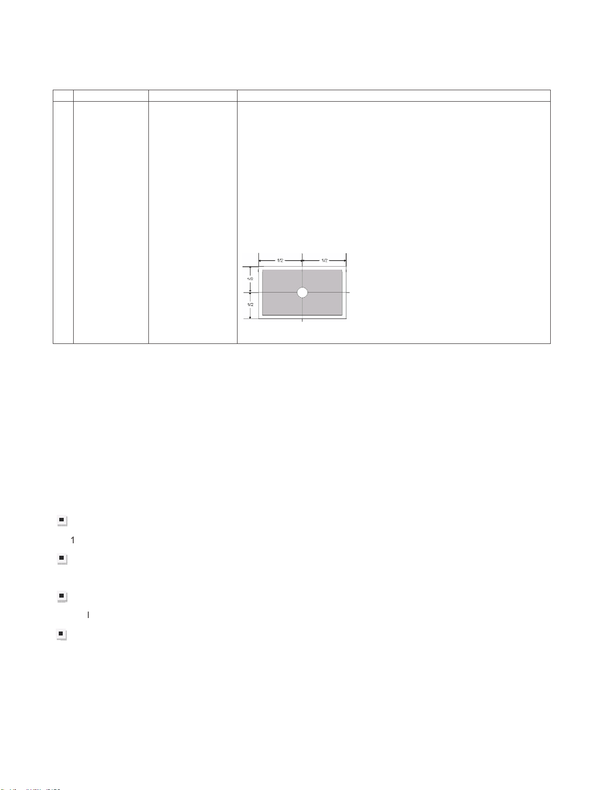
1BIAS
adjustment
(LCD module
Adjustment
Item)
Adjustment must
be done at center
of panel
ERUDECORPNOITIDNOCMETI
1. Enter adjustment mode by using test remote control.
2. By using Remote control, press
3. After press “ENTER”, adjustment pattern will appear..
4. With key volume + / -, adjust until the flicker is minimum appear on
the center of the screen.
5. After satisfied with step 4, press “ENTER” to OFF.
[ Caution item ]
*Adjustment done during no signal from ANT (due to brightness will
change because of active backlight)
[ Adjustment Location ]
䊺䚸䊼
to select
[VCOM ADJ]
9.2) PICTURE ADJUSTMENT
(9.2.1) Equipment confirmation
Before adjustment, need to confirm that Adjustment equipment and signal generator have set to SHARP
LCD US used.
Confirmation of signal from generator (setting to spec level)
posite signal (NTSC)[For ‘T’ & ‘X’ model ] 㸸0.714Vp-p ± 0.02Vp-p (pedestal to white level)
(PAL/SECAM)[For ‘X’ model only] 㸸0.7 Vp-p ± 0.02Vp-p (pedestal to white level)
Component signal (50Hz) 㸸Y level 㸸0.7 Vp-p ± 0.02Vp-p (pedestal to white lev
Pb, Pr level 㸸0.7 Vp-p ± 0.02Vp-p
Component signal 㸸Ylevel 㸸0.7 Vp-p ± 0.02Vp-p (pedestal to white level)
Pb, Pr level 㸸0.7 Vp-p ± 0.02Vp-p
ogue RGB : RGB level 㸸0.7 Vp-p ± 0.02Vp-p (pedestal to white level)
el)
5 – 10
Page 26
( 9.2.2 ) Adjustment Mode
ERUDECORPNOITIDNOCMETI
1 Adjustment Mode Press the test key at the test remote control
(9.2.3) PAL Signal Adjustment [For ‘X’ model ONLY. Skip for ‘T’ model]
ERUDECORPNOITIDNOCMETI
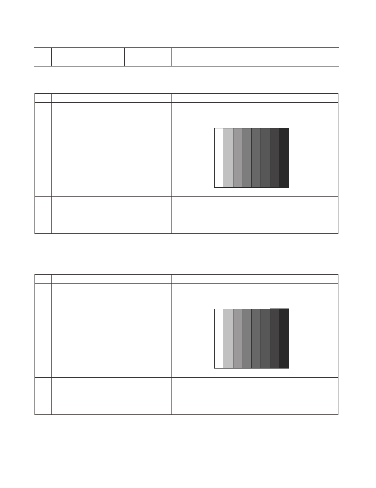
1 Setting [Signal]
PAL Full-field
࣭Feed the PAL Full-field Colour Bar signal(75% colour
saturation) to INPUT 6
Colour Bar
[Terminal]
INPUT 6
Video input
100% WhiteЍЋBlack
LC-60G9T / LC-70G9T
2 Auto Adjustment Test Mode page
[4/33]
At the related page, move cursor to [PAL ADJ], press OK.
[PAL ADJ OK] appears when finished.
*Caution: Please execute (6) TUNER adjustment afterwards when adjust PAL signal of (3) after all
adjustments are completed.
(9.2.4) NTSC Signal Adjustment [For ‘X’ and ‘T’ model]
ERUDECORPNOITIDNOCMETI
1 Setting [Signal]
N358 Full-field
࣭Feed the NTSC-J Full-field Colour Bar signal(75% colour
saturation) to INPUT 6
Colour Bar
[Terminal]
INPUT 6
Video input
100% WhiteЍЋBlack
2 Auto Adjustment Test Mode page
[4/33]
At the related page, move cursor to [N358 ADJ], press OK.
[N358 ADJ OK] appears when finished.
5 – 11
Page 27
LC-60G9T / LC-70G9T
Ќ
00%
[
]
Ќ
00%
[
]
(9.2.5) SECAM Signal Adjustment [For ‘X’ model ONLY. Skip for ‘T’ model]
1 Setting [Signal]
SECAM Full-field
Colour Bar
[Terminal]
INPUT 6
Video Input
2 Auto Adjustment Test Mode page
[4/33]
(9.2.6) TUNER Signal Adjustment [For ‘X’ and ‘T’ model]
࣭Feed the SECAM Full-field Colour Bar signal(75% colour
saturation) to INPUT 6
100% White
At the related page, move cursor to [SECAM ADJ], press OK.
[SECAM ADJ OK] appears when finished.
ЍЋ
ERUDECORPNOITIDNOCMETI
Black
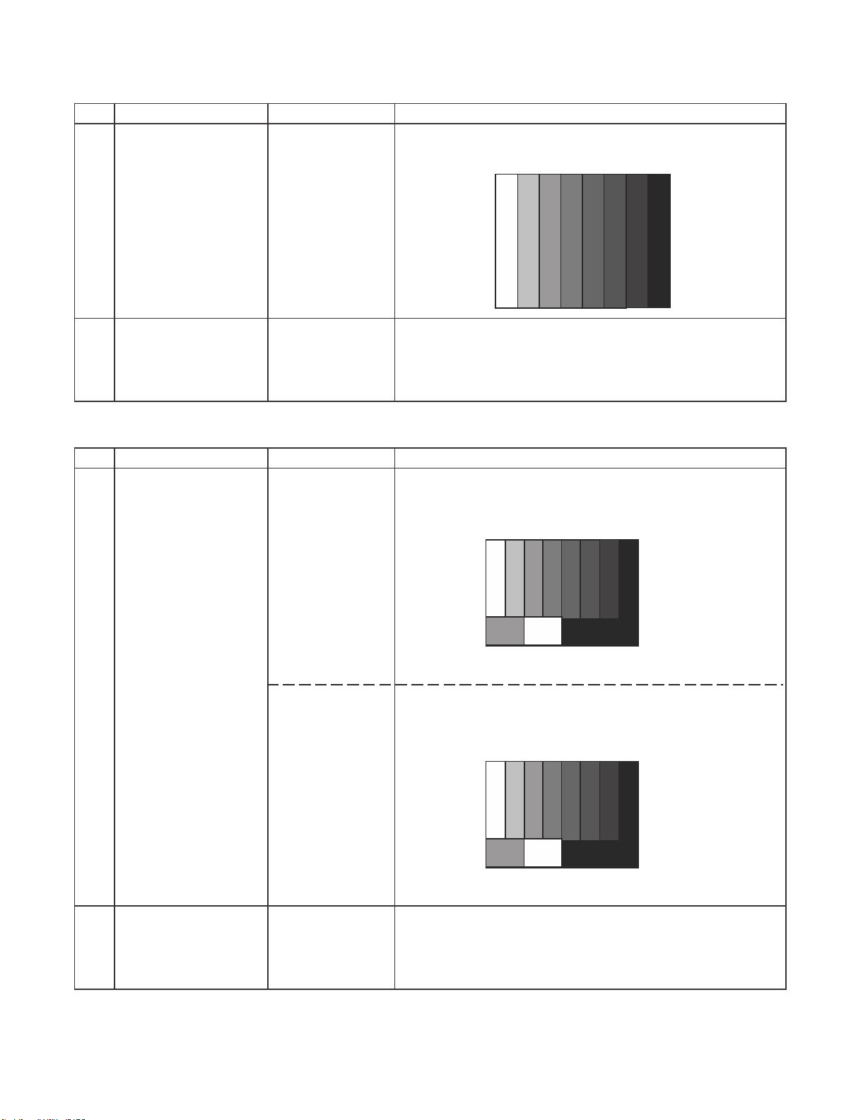
1 Setting [For ‘X’ model]
[Signal]
PAL split color bar
Internal UV
[Terminal]
TUNER
[For ‘T’ model]
[Signal]
NTSC split color
bar
Internal UV
[Terminal]
TUNER
ERUDECORPNOITIDNOCMETI
࣭Feed the Internal signal (PAL colour bar E-12) to tuner RF.
Picture level and Sync Level 7:3
RF CH E-12
White 1
Feed the Internal signal (NTSC colour bar US-10CH) to
tuner RF. Picture level and Sync Level 7:3
RFCH US-10
White1
2 Auto Adjustment
[For ‘X’ & ‘T’ model]
Test Mode page
[3/33]
At the related page, move cursor to [TUNER ADJ], press OK.
[TUNER ADJ OK] appears when finished.
5 – 12
Page 28
(9.2.7) Component 15K Adjustment [For ‘X’ and ‘T’ model]
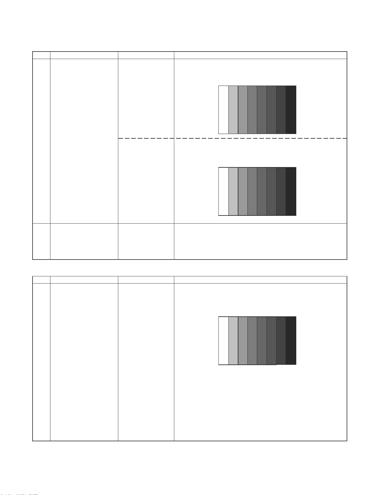
1 Setting [For ‘X’ model]
[Signal]
COMP 15K 50Hz
࣭Feed the COMPONENT 15K 50Hz (576i) 100% Full-field
Colour Bar signal(100% colour saturation) to
COMPONENT INPUT 5
(576i)
100% Full-field
Colour Bar
LC-60G9T / LC-70G9T
ERUDECORPNOITIDNOCMETI
[Terminal]
100% White
ЍЋ
COMPONENT
INPUT 5
[For ‘T’ model]
[Signal]
COMP 15K 60Hz
(480i)
࣭Feed the COMPONENT 15K 60Hz (480i) 100% Full-field
Colour Bar signal(100% colour saturation) to
COMPONENT INPUT 5
100% Full-field
Colour Bar
[Terminal]
100% White
ЍЋ
COMPONENT
INPUT 5
2 Auto Adjustment
[For ‘X’ & ‘T’ model]
Test Mode page
[6/33]
At the related page, move cursor to [COMP 15K ALL ADJ],
press OK.
[COMP 15K ALL OK] appears when finished.
(9.2.8) HDTV Adjustment (Component 33K) [For ‘X’ and ‘T’ model]
1 Setting [For ‘X’ model]
[Signal]
COMP 33K 50Hz
(1080i/50Hz)
࣭Feed the COMPONENT 33K 50Hz (1080i) 100% Full-field
Colour Bar signal(100% colour saturation) to
COMPONENT INPUT 5
100% Full-field
Colour Bar
Black
Black
ERUDECORPNOITIDNOCMETI
[Terminal]
COMPONENT
INPUT 5
100% White
5 – 13
ЍЋ
Black
Page 29

LC-60G9T / LC-70G9T
[For ‘T’ model]
[Signal]
COMP 33K 60Hz
(1080i/60Hz)
100% Full-field
Colour Bar
࣭Feed the COMPONENT 33K 60Hz (1080i) 100% Full-field
Colour Bar signal(100% colour saturation) to
COMPONENT INPUT 5
[Terminal]
100% White
ЍЋ
COMPONENT
INPUT 5
2 Auto Adjustment
[For ‘X’ & ‘T’ model]
Test Mode page
At the related page, move cursor to [HDTV ADJ], press OK.
[7/33]
[HDTV ADJ OK] appears when finished.
(9.2.9) PC ( Analogue D-sub 15 pin) Signal adjustment [For ‘X’ and ‘T’ model]
1 Setting
[For ‘X’ & ‘T’ model]
[Signal]
࣭Feed the XGA 60Hz 100% Full field colour bar signal (100%
colour saturation) to PC INPUT
XGA 60Hz
100% Full field
Colour Bar
Black
ERUDECORPNOITIDNOCMETI
2 Auto Adjustment
[Terminal]
PC INPUT 7
[For ‘X’ & ‘T’ model]
Test Mode page
[8/33]
100% White
ЍЋ
Black
At the related page, move cursor to [ANALOG PC ADJ], press
OK.
[ANALOG PC ADJ OK] appears when finished.
5 – 14
Page 30
10㸧WHITE BALANCE ADJUSTMENT/ GAMMA ADJUSTMENT
4
10.1㸧White Balance Adjustment / Gamma Adjustment
㸯
㸰
Setting
Auto
Adjustment
Brightness㸸MAX㸦+16㸧
AV MODE: DYNAMIC
Active Backlight: OFF
OPC: OFF
Set the luminance
㸦
meter on the centre of the
screen
[command]
Adjustment mode
Setting
Multi point adj.
Gamma adjustment mode
setting
㸧
KRSW0001
KKT10037
KYOF0000
OSDS0001
SBSL0016
MSET0011
GC6P0011
Point 6
229
LEV60
GCC6****
MG6G****
MG6Y****
MG6B****
MG6R****
Point 5
LEV50
173
GCC5****
MG5G****
MG5Y****
MG5B****
MG5R****
Point 4
LEV40
133
GCC4****
MG4G****
MG4Y****
MG4B****
MG4R****
Point 3
LEV30116
GCC3****
MG3G****
MG3Y****
MG3B****
MG3R****
For the details of white balance adjustment procedure, please refer
to white balance adjustment spec for Kameyama model ver 1.9.
1. Confirm the set condition.
2. Connect the white balance jig.
3. Through RS-232C command, adjustment mode screen is
displayed
ㄪᩚἲࠚ
㸯.R/C࡚ࠕࣔࢽࢱ࣮ㄪᩚᕤ⛬ࠖࢥ࣮ࢻࢆ㏦ಙࡍࡿࠋ
㸰.6 㺬㺽㺐㺻㺢┠ࢆᣦᐃࡉࢀࡓ㝵ㄪタᐃࡋࠊ࣐࢞ࣥㄪᩚࡢ 6 ࣏ࣥࢺ
┠ࡢ㍤ᗘࢆ ᐃࡋࠊྲྀᚓࡋࡓ㍤ᗘࡢ 10 ಸࢆタᐃࡍࡿࠋ୍␒ᙉ࠸
ⰍࢆᅛᐃⰍࡋ࣐ࢼࢫㄪᩚ࡛ᇶ‽್࡞ࡿࡼ࠺ RGB ࢆㄪᩚ
ࡍࡿࠋ
RGB ࡢ㝵ㄪࢆࢭࢵࢺࡋࡓᚋࠊYe ࡢ㝵ㄪࢆ⟬ฟࡍࡿࠋ
R㸼G ࡢሙྜ…Ye=G×1.05
ࡓࡔࡋࠊYe ࡢ್ࡀึᮇ್(916)ࢆ㉸࠼ࡓሙྜࡣࠊ916 ࡍࡿ
RӌG ࡢ
ሙྜ…Ye=R×1.05
ࡓࡔࡋࠊYe ࡢ್ࡀึᮇ್(916)ࢆ㉸࠼ࡓሙྜࡣࠊ916 ࡍࡿ
ୖグ᮲௳ᘧࡽ⟬ฟࡉࢀࡓ Ye ࡢ್ࢆ MG6YXXXX ࡛ࢭࢵࢺࡍ
ࡿࠋ
ᇶ‽್᮰ࡍࡿࡲ࡛⧞ࡾ㏉ࡋ RGBYe ࢆㄪᩚࡍࡿࠋ
䠏.(STEP2)6 䢊䢛䡮䢙䢀┠䛾ㄪᩚᚋ㍤ᗘ Y
ศග㍤ᗘィ(SR-LEDW,SR-3 ➼)䛻䜘䜛⿵ṇ㍤ᗘ Y
R6,G6,B6 䜢 2-1 䛻䛶ィ⟬䛧䛯 6 䢊䢛䡮䢙䢀┠䛾 R,G,B ㄪᩚ್䛸䛩䜛䚹
Y
䠘258 䛛䛴㻌 R6䠙916 䛾ሙྜ䚸௨ୗ䛾ฎ⌮䜢⾜䛖䚹
WB6-SR3
䠙(268/Y
GAIN
G6
WB6-SR3
ణ䛧䚸Y=355…440cd/m
GAIN
䠚1.10 䛾䚸GAING6=1.10 䛸䛩䜛䚹
G6
ィ⟬ᚋ䛾 6 䢊䢛䡮䢙䢀┠䛾 G 䜢 G6'䠙GAIN
ィ⟬ᚋ䛾 6 䢊䢛䡮䢙䢀┠䛾 Ye 䜢 Ye6'䠙1.05×min(R6,G6')䛸䛩䜛䚹
ィ⟬ᚋ䛾 6 䢊䢛䡮䢙䢀┠䛾 B 䜢 B6’䠙B6×G6’䠋G6 䛸䛩䜛䚹
ణ䛧䚸R6',G6',B6'䛜 916 䜢㉸䛘䜛䚸916 䛸䛩䜛䚹
.5 㺬㺽㺐㺻㺢┠ࢆᣦᐃࡉࢀࡓ㝵ㄪタᐃࡋࠊ ᐃࡋࡓ㍤ᗘ(cd/m2)ࡢ 10
ಸࢆ࣐࢞ࣥㄪᩚࡢ 5 ࣏ࣥࢺ┠タᐃࡍࡿࠋ
G ࡢ⿵ṇ್㸦692×6 㺬㺽㺐㺻㺢┠ G ್/916㸧(➃ᩘࡣᅄᤞධ)࠾ࡼࡧ
Ye ࡢ⿵ṇ್(692×6 ࣏ࣥࢺ┠Ye ್/916)(➃ᩘࡣᅄᤞධ)ࢆࢭ
ࢵࢺࡋࠊᇶ‽್࡞ࡿࡼ࠺ RB ࢆ±ࡋ࡚ㄪᩚࡍࡿࠋ
5.4 㺬㺽㺐㺻㺢┠ࢆᣦᐃࡉࢀࡓ㝵ㄪタᐃࡋࠊ ᐃࡋࡓ㍤ᗘ(cd/m
ಸࢆ࣐࢞ࣥㄪᩚࡢ 4 ࣏ࣥࢺ┠タᐃࡍࡿࠋ
G ࡢ⿵ṇ್㸦532×6 㺬㺽㺐㺻㺢┠ G ್/916㸧㸦➃ᩘࡣᅄᤞධ㸧࠾ࡼ
ࡧ Ye ࡢ⿵ṇ್(532×6 ࣏ࣥࢺ┠ Ye ್/916)(➃ᩘࡣᅄᤞධ)
ࢆ㺜㺍㺢ࡋࠊᇶ‽್࡞ࡿࡼ࠺ RB ࢆ±ࡋ࡚ㄪᩚࡍࡿࠋ
6.3 㺬㺽㺐㺻㺢┠ࢆᣦᐃࡉࢀࡓ㝵ㄪタᐃࡋࠊ ᐃࡋࡓ㍤ᗘ(cd/m
ಸࢆ࣐࢞ࣥㄪᩚࡢ 3 ࣏ࣥࢺ┠タᐃࡍࡿࠋ
ERUDECORPNOITIDNOCMETI
䜢 ᐃ䛧䚸䛭䛾⤖ᯝ䜢
WB6
)^(1/2䠅
2
┦ᙜ䚸365䞉䞉䞉453cd ┦ᙜ䚸
×G6 䛸䛩䜛䚹
G6
LC-60G9T / LC-70G9T
䛻⿵ṇ䛩䜛䚹
WB6-SR3
2
)ࡢ 10
2
)ࡢ 10
5 – 15
Page 31

LC-60G9T / LC-70G9T
Point 2
LEV20
GCC2****
MG2G****
MG2Y****
MG2B****
MG2R****
Point 1
LEV10
GCC1****
MG1G****
MG1Y****
MG1B****
MG1R****
WB adj value data input
MSET0003
MIN࣭MAX point
GCP00000
GCP70255
GCC0****
GCC7****
Adj. Value data input
GCST0001
Measure Luminance after
adjustment
CHGM1255
074
045
G ࡢ⿵ṇ್㸦464×6 㺬㺽㺐㺻㺢┠ G ್/916㸧㸦➃ᩘࡣᅄᤞධ㸧࠾ࡼ
ࡧ Ye ࡢ⿵ṇ್(464×6 ࣏ࣥࢺ┠ Ye ್/916)(➃ᩘࡣᅄᤞධ)
ࢆ㺜㺍㺢ࡋࠊᇶ‽್࡞ࡿࡼ࠺ RB ࢆ±ࡋ࡚ㄪᩚࡍࡿࠋ
7.2 㺬㺽㺐㺻㺢┠ࢆᣦᐃࡉࢀࡓ㝵ㄪタᐃࡋࠊ ᐃࡋࡓ㍤ᗘ(cd/m
2
)ࡢ 10
ಸࢆ࣐࢞ࣥㄪᩚࡢ 2 ࣏ࣥࢺ┠タᐃࡍࡿࠋ
G ࡢ⿵ṇ್㸦296×6 㺬㺽㺐㺻㺢┠ G ್/916㸧㸦➃ᩘࡣᅄᤞධ㸧࠾ࡼ
ࡧ Ye ࡢ⿵ṇ್(296×6 ࣏ࣥࢺ┠ Ye ್/916)(➃ᩘࡣᅄᤞධ)
ࢆ㺜㺍㺢ࡋࠊᇶ‽್࡞ࡿࡼ࠺ RB ࢆ±ࡋ࡚ㄪᩚࡍࡿࠋ
2
8.1 㺬㺽㺐㺻㺢┠ࢆᣦᐃࡉࢀࡓ㝵ㄪタᐃࡋࠊ ᐃࡋࡓ㍤ᗘ(cd/m
)ࡢ 10
ಸࢆ࣐࢞ࣥㄪᩚࡢ 2 ࣏ࣥࢺ┠タᐃࡍࡿࠋ
G ࡢ⿵ṇ್㸦
180×6 㺬㺽㺐㺻㺢┠ G ್/916㸧㸦➃ᩘࡣᅄᤞධ㸧࠾ࡼ
ࡧ Ye ࡢ⿵ṇ್(180×6 ࣏ࣥࢺ┠ Ye ್/916)(➃ᩘࡣᅄᤞධ)
ࢆ㺜㺍㺢ࡋࠊᇶ‽್࡞ࡿࡼ࠺ RB ࢆ±ࡋ࡚ㄪᩚࡍࡿࠋ
9㸬MSET0003 ࢥ࣐ࣥࢻ࡚ࠊㄪᩚ್ࢆ᭩ࡁ㎸ࡴࠋAC 㟁※ࢆษࡿࠋ
10㸬MIN࣭MAX ㄪᩚ㝵ㄪࢆᣦᐃࡉࢀࡓ㝵ㄪタᐃࡋࠊ࣐࢞ࣥㄪᩚࡢ
MAX ࣏ࣥࢺࡢ㍤ᗘࢆ ᐃࡍࡿࠋMAX ࡣྲྀᚓࡋࡓ MAX ㍤ᗘ
2
)ࡢ 10 ಸࢆタᐃࡍࡿࠋMIN ࡣྲྀᚓࡋࡓ MAX ㍤ᗘࣃࢿ
(cd/m
ࣝ SPEC ࡢࢥࣥࢺࣛࢫࢺẚࡽ MIN ㍤ᗘ(cd/m
ࡢ㍤ᗘࡢ 100 ಸ
ࢆタᐃࡍࡿࠋ
2
)ࢆ⟬ฟࡋࠊࡇ
11㸬GCST0001 ࢥ࣐ࣥࢻ࡚ࠊㄪᩚ್ࢆ᭩ࡁ㎸ࡳ AC 㟁※ࢆษࡿࠋ
6 㺬㺽㺐㺻㺢ࡢ RGBYe ࡢึᮇ್㸸 タᐃ㝵ㄪ 916
1㹼5 㺬㺽㺐㺻㺢ࡢ RGB ࡢึᮇ್㸸 ྛ㺬㺽㺐㺻㺢ࡢ G ࡢ⿵ṇ್
ࡓࡔࡋ 1㹼5 㺬㺽㺐㺻㺢ࡢ Ye ࡢึᮇ್㸸ྛ㺬㺽㺐㺻㺢ࡢ Ye ࡢ⿵ṇ್
ὀព㸸
ࢸࢫࢺࣃࢱ࣮ࣥฟຊࢥ࣐ࣥࢻࢆᐇ⾜ᚋࠊࣃࢱ࣮ࣥฟຊࡲ
࡛ࡢീ㐜ᘏࡀ࠶ࡿࡓࡵࠊ“OK”ࡢ㏉ࡾࡽୗグ Wait 㛫
௨ୖᚅࡗࡓᚋࠊⰍᗘ࣭㍤ᗘࢆ ᐃࡍࡿࡼ࠺ࡋ࡚ୗࡉ࠸ࠋ
ീ㐜ᘏ㔞㸸70ms
㸦࣓࣐ࣥࢥ࣭ࣥLCD ࢥࣥࢺ࣮ࣟࣛࡢࢺ࣮ࢱࣝ㐜ᘏ㔞್᭱㸧
࠙ㄪᩚ್ࠚ
ۼᢏ⾡㒊ᥦฟࡢࠕࢸ࣮ࢳࣥࢢࢭࢵࢺࠖ‽ࡎࡿࠋ
࠙ㄪᩚᇶ‽್ࠚ ᐃჾ㸸[Minolta CA-210 ] ᢏ⾡ ᐃჾ
㺸㺫㺼㺷 ᇶ‽್ ㄪᩚ㺛㺫㺽㺍㺖 ᳨ᰝ㺛㺫㺽㺍㺖
㺬㺽㺐㺻㺢 6916
㺬㺽㺐㺻㺢 5692
㺬㺽㺐㺻㺢 4
㺬㺽㺐㺻㺢 3
㺬㺽㺐㺻㺢 2
㺬㺽㺐㺻㺢 1
532
464
296
180
X= 0.272
y= 0.277
X= 0.272
y= 0.277
X= 0.272
y= 0.277
X= 0.272
y= 0.277
X= 0.272
y= 0.277
X= 0.272
y= 0.277
±0.0010 ±0.0020
±0.0010 ±0.0020
±0.0015 ±0.0030
±0.0020 ±0.0040
±0.0030 ±0.0060
±0.0040 ±0.0080
ഛ⪃ ᳨ᰝࡢࢭࢵࢺ᮲௳
AV MODE : [DYNAMIC]
Monochro : ON
Aging Time㸸 Min. 60
5 ศ
5 – 16
Page 32

11 ). KEY DATA INPUT
11.1) EDID DATA INPUT ( Main PWB : QPWBXG216WJ**)
ERUDECORPNOITIDNOCMETI
1 HDMI EDID
INPUT
ANALOG RGB
EDID INPUT
(Main PWB)
11.2)MACADDRESS DATA INPUT (Main PWB : QPWBXG216WJ**)
Please refer to Document “Caution Item for Production “.
11.3)CIPLUS KEY DATA INPUT (Main PWB : QPWBXG216WJ**) [For X Model Only]
Please refer to Document “Caution Item for Production”.
Inspection mode
Confirm the file
name/version.
1. Enter the Adjustment Mode.
2. Move cursor at [HDMI EDID WRITE] and press [ENT] key.
[OK] appear when finish.
(HDMI and Analogue RGB input data together)
[ Caution Item ]
Please execute data input after setting the model distinction.
The data based on model distinction information is recorded in
EEPROM.
LC-60G9T / LC-70G9T
11.4) WMDRM KEY DATA INPUT (Main PWB : QPWBXG216WJ**)
Please refer to Document “Caution Item for Production”.
12. CONFIRMATION ITEM
(1) HDMI-CEC Check
Confirm the operation of HDMI-CEC circuit.
(2) LAN Check
Confirm the connection and communication of PC and LAN terminal.
13. FACTORY SETTING
AC power is plug off after shipment setting is done.
Caution: Do not plug on again after shipment setting is done. If do, please re-do the shipment setting. Do not
off with remote control.
5 – 17
Page 33
LC-60G9T / LC-70G9T
ERUDECORPNOITIDNOCMETI
Factory setting AC power off to exit the
factory setting.
Go to adjustment mode page [2/33], move cursor at [INDUSTRY INIT]
and press [OK] at Remote control.
ޚFor X model, please select destination either
- AUSTRALIA for COUNTRY of AUSTRALIA
- NEWZEALAND for COUNTRY of NEW ZEALAND
- GENERAL for others ASIA COUNTRIES
Remark: GENERAL setting is for MALAYSIA/ SINGAPORE/
INDONESIA/ SINGAPORE/ VIETNAM/ PHILIPINNE/ THAI
MIDDLE EAST
ޚ For T model, just press [ENTER] at Remote Control and no
selection need to be done.
////////// appear, after that
SUCCESS --------- Destination appear after finished.
If success, background colour is GREEN , if failed, background colour
is RED
The followings are initialised to factory setting
1) User setting
2) Channel data (e.g. broadcast frequencies)
3) Manufacturer’s option settings
4) Password data
14. SOFT/ ROM VERSION
1.Main microprocessor
950X/951X
XIAN_LE950X_xxx.USB
XIAN_LE950X_xxx.UVP
XIAN_LE950X_xxx.PCC
G9T
XIAN_G9T_xxx.USB
XIAN_G9T_xxx.UVP
XIAN_G9T_xxx.PCC
2.Monitor microprocessor
XIANSUBxxx.SMB
3.T-CON ROM
LC-60LE950X/951X,LC-60G9T
PRIMEROSE_CMB_601F8(YS2)_2012100330110002_3FAAEBD.ROM
LC-70LE950X/951X,LC-70G9T
PRIMEROSE_CMB_701FC(YS2)_2012100330550004_3B59E6E.ROM
5 – 18
Page 34

[2] PUBLIC MODE SETTING PROCEDURE
1. How to start Public Mode
Starting the Public Mode
• There is one following ways to display the PUBLIC Mode setting screen.
1) Method of needing password
a) Press the "INPUT" and "VOL (+)" keys on the set at once and turn on the power.
b) Display the Pass Word input screen.
LC-60G9T / LC-70G9T
Enter password
Operation procedure
• The initial input position is the digit at the left end.
• For the numeric keys “0” to “9” of R/C, key input is accepted.
Input of the other keys is prohibited.
• Change “—” to “ * ” by inputting the numeric key at the input position, and shift the input position rightward one digit.
• When three digits are completely input, the Pass Word is judged.
c) Check the Pass Word by inputting three digits.
If the Pass Word “0” “2” “7”, it shifts to the PUBLIC Mode setting screen.
In another case, the screen is erased, and it operates in the ordinary mode.
2) In the adjustment process mode, turn on “PUBLIC MODE”. Also press the “CH ( )” or “CH ( )” and “VOL(+)” keys on the set at once and turn
on the power.
Enter password
Enter password
2. How to exit Public Mode
There are the following ways to quit the public mode setup screen.
x Turn off “PUBLIC MODE” in the adjustment process mode. ( ) m This way alone is not for quitting the setup screen, but for quitting the mode itself.
x Turn off the power with the “POWER” key. ( )
x Select “EXECUTE”. ( )
... “PUBLIC MODE” stays on in the adjustment process mode.
... The settings will be back to the factory ones.
3. Public Mode Setting Values
x With the factory settings made, the public mode settings get initialized. (The adjustment process remains intact.)
5 – 19
Page 35

LC-60G9T / LC-70G9T
4. Public Mode Menu
The guidance is not displayed on screen.
Setup procedure
x To move the cursor up and down, use the “cursor UP/DOWN” key (remote controller) and “CH ( )/( )” key (remote controller and set).
x To change the settings, use the “cursor RIGHT/LEFT” key (remote controller) and “VOL (+)/(–)” key (remote controller and set).
x To save new settings, keep the cursor at “EXECUTE” and use “ENTER” key (remote controller and set).
5 – 20
Page 36
LC-60G9T / LC-70G9T
5. On Setting Items
1) Power ON fixed [POWER ON FIXED]
Option “VARIABLE”, “FIXED_ALL”, “FIXED_BODYKEY” or “RCRESPOND” (loop enabled)
Default “VARIABLE”
Function • VARIABLE
• FIXED_ALL
• FIXED_BODYKEY
• RC RESPOND
Key disabled when set
other than default
Remarks • When selecting to “FIXED_ALL”, function related standby factors (see below) doesn’t work. and not selecting.
If the power button is pressed in the ordinary mode in setting to “FIXED_ALL” and “FIXED_BODYKEY”, the caution is displayed for 5 seconds.
• OFF TIMER (SLEEP) (*Only when setting to FIXED_ALL)
OFF TIMER (Sleep)
No operation OFF
No signal OFF (including the power management)
* These items does not exist according to the model.
: “POWER/RECEPTION” key on TV unit or remote control is enabled.
: “POWER/RECEPTION” key on TV unit or remote control is disabled.
: Only the “MAIN POWER” key on TV unit is disabled (The remote control is enabled).
: The main unit’s POWER switch toggles between ON and Standby (the same operation by the
remote control).
When power button on the main unit is pressed When power button on R/C is pressed
No Power off by power button.
* The OSD display is an example.
If another ODS is previously displayed, the status is reset (MENU or similar).
2) Instantaneous current shutdown setting in turning off the power [SHUT DOWN MODE]
Option “NORMAL” or “QUICK”
Default NORMAL
Function • This function decides whether
NORMAL
QUICK
Remarks In selecting “QUICK”, the function does not work for the following items. (selection impossible.)
• ON TIMER, QUICK START, DIGITAL FIXED, etc.
* These items does not exist according to the model.
3) Volume maximum level [MAXIMUM VOLUME]
Option 0~100 (loop disabled)
Default 100
Function The volume cannot be increased more than the adjusted value (the main unit’s speaker only).
Remarks • When setting to 59 or less, only the figure is displayed in the normal mode; the volume bar is not displayed.
• The volume of the headphones is limited.
• The setting is impossible when VOLUME FIXED is set to FIXED.
scanning digital tuner is enabled or disabled when the power is standby.
: Scanning digital tuner is enabled when the power is standby.
: Scanning digital tuner is disable.
It is possible to put into the standby state instantaneously due to power off input, when the
power is standby.
Immediately, state is a complete standby.
No Power off by remote control.
5 – 21
Page 37

LC-60G9T / LC-70G9T
4) Volume fixed [VOLUME FIXED]
Option “VARIABLE”, “FIXED”, “ACCTRL” or “AC/RCCTRL” (loop enabled)
Default “VARIABLE”
Function • VARIABLE
• FIXED
• AC CTRL
• AC/RC CTRL
Exception • In the adjustment process, the volume can be set to any level regardless of this setting.
Disabled key when
setting to FIXED
Remarks • [MAXIMUM VOLUME] has priority to [VOLUME FIXED]
• VOLUME UP/DOWN [both remote control and main unit]
•MUTE
* Main units's key is enabled for operating menu.
* When setting to FIXED, Maximum volume is fixed.
• The volume of the headphones is fixed.
• When setting to “FIXED”, the volume is not displayed in operating Disabled key.
• In menu operation, the main unit’s keys (Vol (+/-)) are enabled.
: The volume is not fixed.
: The volume is fixed to the value adjusted in the volume fixed level.
: The unit starts at the volume specified in the volume fixed level, when power is turned on in the
case of the AC-ON only.
: The unit starts at the volume specified in the volume fixed level, when power is turned on in
any case.
(ACoON, remote controloON, main utit's keyoON)
5) Volume fixed level [VOLUME FIXED LEVEL]
Option 0~100 (loop disabled)
Default 30
Function The volume is fixed to the adjuste
Exception • In the adjustment process, the volume can be set to any level regardless of this setting.
Remarks • When [VOLUME FIXED] is set to “VARIABLE”, the setting cannot be changed.
6) Remote control operation [RC BUTTON]
Option “RESPOND”, “NORESPOND” or “LIMITED” (loop enabled)
Default “RESPOND”
Function The operation of the remote control’s keys is set.
RESPOND
NO RESPOND
LIMITED
Exception • All the keys are enabled regardless of this setting while entering the adjustment process mode, inspection mode or
Public Mode setting screen.
Remarks The enable keys when setting to “LIMITED” are depended on Model.
7) Main Unit Operation [PANEL BUTTON]
Option “RESPOND” or “NO RESPOND” (loop enabled)
Default “RESPOND”
Function • RESPOND
• NO RESPOND
Exception • The start operation in the adjustment process mode, inspection mode are enabled regardless of this setting.
• All the keys are enabled regardless of this setting while entering the adjustment process mode, inspection mode or
Public Mode setting screen.
• For the models with the MENU key on the main unit, menu operation is possible regardless of the setting during the
initial setting when the power is turned on for the first time.
d value (the main unit’s speaker only).
: The remote control’s keys in the normal state are enabled.
: The remote control’s keys in the normal state are disabled.
The POWER key (RECEPTION/STANDBY key) is also disabled.
: Only a part of keys (CHANNEL, etc.) is enabled and other keys are disabled.
: The main unit’s keys are enabled.
: The main unit’s keys are disabled excluding the POWER key (RECEPTION/STANDBY key).
5 – 22
Page 38
LC-60G9T / LC-70G9T
8) Menu operation [MENU BUTTON]
Option “RESPOND” or “NO RESPOND” (loop enabled)
Default “RESPOND”
Function The MENU key on the main unit and remote control is decided whether it is enabled or disabled.
Exception • RESPOND
• NO RESPOND
Disabled key excluding
Menu key when setting
to not default
Remarks When setting to “NO RESPOND”
9) AV position fixed [AV POSITION FIXED]
Option “VARIABLE” or “FIXED” (loop enabled)
Default “VARIABLE”
Function • VARIABLE
rks • When receiving the sound select direct keys (AV POSITION key, OPC, DOLBY key, etc.), only the actual state is
Rema
All the direct transition keys to menu display. (AUTO PRESET, MANUAL MEMORY and others)
* These keys does not exist according to the model.
• For the models with the MENU key on the main unit, menu operation is possible regardless of the setting while the
initial setting when the power is turned on for the first time.
• FIXED
displayed; no setting is changed.
* These keys does not exist according to the model.
• The settings for the Public mode are retained after the personal data is initialized, each item for the AV position and
image/sound adjustment are not initialized.
: The manu key is enabled.
: The manu key is disabled.
: All the keys are enabled regardless of this setting while entering the process mode, inspection
mode or Public Mode setting screen.
: AV position is not fixed.
: AV position is fixed.
: The image/sound adjustment items in the menu are fixed in the selected state.
: When receiving “AV POSITION” of the remote control, only the actual state is displayed, and
setting is not changed.
10) OSD display [ON SCREEN DISPLAY]
Option “YES”, “NO” or “LIMITED” (loop enabled)
“LIMITED” is looped only in case of need (destination).
Default “YES”
Function • YES
•NO
•LIMITED
Key which may be
enabled
(Example of the confusing key)
Disabled key when
setting to not default
Remarks • When setting to “NO”,
• It is OK in the case that simple input select occur or the original state returns soon automatically.
• When setting to “NO”, the keys which is related to visibility of the screen and sound cannot be used.
STILL IMAGE, SCREEN DISPLAY, OFF TIMER, AV POSITION, BRIGHTNESS SENSOR, SCREEN SIZE SELECT,
AUTO PRESET, MANUAL MEMORY, IMAGE SELECT, SOUND SELECT, LANGUAGE, Closed caution
* Disabled keys dependeds on the models.
* These items does not exist according to the model.
hen setting to “NO”,
•W
: OSD is displayed.
: The following OSD is not displayed.
Registration, setting, adjustment menu, channel call, volume bar, and input select.
: Only a part of OSD (CH call: “New Information” etc...) is not displayed.
ON TIMER (Watching reservation) is cleared.
OFF TIMER “SLEEP” is cleared.
These Displays (Version-up, Public mode setting screen, Pass Word input screen of Public
Mode, the adjustment process mode, K mark of inspection mode) are enabled regardless of
this setting.
5 – 23
Page 39

LC-60G9T / LC-70G9T
11) Start mode [INPUT MODE START]
Option “NORMAL” or “Input source 1 (input selection or channel)” ... (loop enabled)
Default “NORMAL”
Function Which kinds of input source or channel is decided when the power turning on.
NORMAL : The content of the last memory is followed.
Remarks • When setting to not Normal, ON TIMER (Watching reservation) has priority.
• When setting to “NORMAL”, [INPUT MODE FIXED] is set to “VARIABLE” and [INPUT MODE FIXED] is prohibited to
select. (selection impossible.)
Example of option: “NORMAL”, “TVD (002TV)”, “INPUT1”, “INPUT2”, “INPUT3”, “HDMI1”, “HDMI2”, “HDMI3”, “HDMI4”.
12) Input fixed [INPUT MODE FIXED]
Option “VARIABLE”, “FIXED”, “ACCTRL” or “AC/RCCTRL” (loop enabled)
Default VARIABLE
Function VARIABLE
Disabled key when
setting to “FIXED”
Remarks • If [INPUT MODE START] is Normal, this function cannot be set.
FIXED
AC CTRL
AC/RC CTRL
CHANNEL (+/-), DIRECT CHANNEL buttons, FLASHBACK, INPUT SELECT, TV/VIDEO, AUTO PRESET,
MANUAL MEMORY, i.LINK, DIRECTINPUTSELECT, ATV, DTV, EPG, RADIO etc...
Set to “VARIABLE” automatically.
• When setting to “FIXED”,
The item related to the channel setting and input selection in Menu are not displayed.
ON TIMER (Watching reservation) is not active.
* These items does not exist according to the model.
: If [INPUT MODE START] is set to Normal, input mode is not fixed.
: When “INPUT MODESTART” is active, it is impossible to switch to another channel or input
source.
: When “INPUT MODESTART” is active the unit starts at the input mode which is selected when
power is turned on in the case of the AC-ON only.
: When “INPUT MODESTART” is active the unit starts at the input mode which is selected
when power is turned on in any case.
(ACoON, remote controloON, main utit's
keyoON)
13) Speaker ON/OFF selection [LOUD SPEAKER]
Option “ON” or “OFF” (loop enabled)
Default ON
Function ON
OFF
Remarks • When the VOL (+/-) key is pressed, the mute icon is displayed for 4 seconds.
• For the MUTE key and sound-related keys, caution is displayed.
• For the headphones, normal operation is possible.
14) Remote control path through [RC PATH THROUGH]
Option “OFF”, “ON: TVRCE” or “ON: TVRCD” (loop enabled)
Default OFF
Function The item decide whether the signal received by the remote control’s light-receiving section is output to the blankpin (9pin)
of RS232C.
OFF
ON: TVRCE
ON: TVRCD
Exception • In the case of “ON: TV RCD”, the start operation in the adjustment process mode, inspection mod are enabled
• In the case of “ON: TV RCD”, all the keys are enabled regardless of this setting while entering the adjustment process
Remarks * Remote control path through does not exist according to the model.
: The sound from the speakers is output.
: The sound from the speakers is not output even if the headphones are not used.
: This function is not active.
: This function is active, and remote contr
: This function is active, but remote control is not active.
regardless of this setting.
mode, inspection mode or Public mode setting screen.
ol is active, too.
5 – 24
Page 40

LC-60G9T / LC-70G9T
15) 232C power ON control [232C POWON]
Option “ENABLE” or “DISABLE” (loop enabled)
Default DISABLE
Function The item decide whether Power ON by the 232C command is enabled/disabled in the standby state.
The same function as 232C command “RSPW”.
ENABLE
DISABLE
: POWR0001 is always enabled.
: Start-up may be impossible at POWR0001.
(If the 232C command reception module is set to OFF, the command is invalid.)
16) Public mode setting [PUBLIC MODE]
Option “OFF” or “ON” (loop enabled)
Default OFF
Function The item decide whether Public mode setting menu are enabled or disabled.
The same item as [PUBLIC MODE] in the adjustment process menu.
OFF
ON
: Public mode is not active.
: Public mode is active.
Remarks Each operation of the Public mode is impossible unless this item is set to ON.
5 – 25
Page 41

LC-60G9T / LC-70G9T
[
]
[[]
Copy mode
[]]
Copy mode
USB TV
[
]
USB TV
USB TV
[
]
[
]
[[]
Copymode
[]]
USB TV
[
]
Done
Copy mode
US TV
USB TV
[
]
[3] USB Clone Specifications
Input “369” as password on the copy mode screen using the same input method as Public Mode on the previous page.
1. Screen Specifications (copy mode <TVoUSB>)
•TVoUSB (sucking from TV)
<FIG 1>
* Do not focus on button before recognition
of USB device and use is possible.
Copy mode
TV USB
USB TV
Start
Start
Press [ENTER]
]
<FIG 2>
Copy mode
TV USB
USB
TV
[
Wait…
[
Start
Wait display blinks for 1 second
during implementation. Change
button to Select color during this
time to disable key reception.
]
]
Processing failed or multiple insertion.Processing successful.
<FIG 4>
<FIG 5>
Press
[UP] or [DOWN]
<FIG 3>
Copy mode
TV USB
Refer to (USB TV <writing to TV>).
• After finishing processes in FIG 2, return the button to Focus color.
• On USB clone display screen in FIG 1 and FIG 5, key reception is disabled except for Up/Down key and Enter key.
• Key reception is disabled in USB clone display screen in FIG 2 to FIG 4.
• After proceeding to FIG 3, 4, turn off the power with AC OFF.
2. Screen Specifications (copy mode <USBoTV>)
•USBoTV (writing to TV)
<FIG 1>
* Do not focus on button before recognition
of USB device and use is possible.
[
Start
St
Start
]
TV USB
<FIG 2>
Copy mode
TV USB
USB TV
Start
St
Start
Press [ENTER]
]
[
Done
Start
Copy mode
TV USB
USB TV
[
Start
[
Wait…
TV USB
Wait display blinks for 1 second
during implementation. Change
button to Select color during this
time to disable key reception.
]
]
[
Failed
[
Start
]
]
Processing failed or multiple insertion.Processing successful.
<FIG 4>
<FIG 5>
Press
[UP] or [DOWN]
<FIG 3>
Copy mode
TV USB
Refer to (TV USB <sucking from TV>).
• After finishing processes in FIG 2, return the button to Focus color.
• On USB clone display screen in FIG 1 and FIG 5, key reception is disabled except for Up/Down key and Enter key.
• Key reception is disabled in USB clone display screen in FIG 2 to FIG 4.
• After proceeding to FIG 3, 4, turn off the power with AC OFF.
[
Start
St
Start
]
TV USB
[
Start
TV USB
BTV
5 – 26
[
Start
[
Failed
]
]
Page 42

LC-60G9T / LC-70G9T
3. USB Clone Restrictions
• Be sure to set the network setting (Setup/View setting/Network setup) after writing the data by USB Clone (USBoTV).
• Use USB memory with a memory capacity of 1M byte or greater.
• The USB memory file system is FAT (FAT32).
• No connection of multiple USB memories to the USB port.
• If the USB memory connection is one connection, carry out clone operations regardless of what USB port it is connected to.
• Up until recognition of the USB device and usage enable, do not focus on the button shown in FIG 1 of the “1. Screen Specifications (copy mode
<TVoUSB>)” and “2. Screen Specifications (copy mode <USBoTV>)” (maximum 45 seconds).
• The following must agree during sucking from TV (TVoUSB) and writing to TV (USBoTV).
Vender name (fixed)
Key information (fixed)
USB Clone Ver.
Inch size
Shipping destination settings
Model name
Software version
5 – 27
Page 43

LC-60G9T / LC-70G9T
CHAPTER 6. TROUBLESHOOTING
TABLE
[1] TROUBLESHOOTING TABLE
[1] TROUBLESHOOTING TABLE
The sound is not emitted from the Speaker & Woofer though the picture has come out.
No sound output in all modes?
YES
Do audio signals output from pins of IC3301 (Digital AV decode & Main CPU) ?
[AP11/CPU_AOLRCK, AR11/CPU_AOBCK, AN9/CPU_AOSDATA0]
YES
Do audio signals input to pins[5,6,7] of IC1703(DSP) ?
NO
Check IC3301 and its peripheral circuits.
NO
Check the line between IC3301 and IC1703.
Do audio signals output from pins of IC1703 ?
YES
[21/AMP_BCLK, 26/AMP_LRCLK, 27/AMP_DATA_LR, 28/AMP_DATA_WO,
30/AMP_MCLK]
YES
In the case that the sound is not emitted from the Speaker , refer to (A).
In the case that the sound is not emitted from the Woofer , refer to (B).
(A)
Do audio signals input to pins[5,6,7,8] of IC1901 (SP_AMP) ?
YES
Do audio signals output from pins of IC1901 ?
[27/OUTML, 30/OUTPL, 11/OUTPR, 15/OUTMR]
YES
Is AMP_MUTE [pin(24)] of IC1901 at "H" ?
YES
Do audio signals input to pins[1&2/L-ch, 3&4/R-ch] of P1903 ?
YES
Check Speaker (right and left) and wire harness.
(B)
Do audio signals input to pins[5,6,7,8] of IC1902 (Woofer_AMP)?
NO
Check IC1703 and its peripheral circuits.
(B)
NO
Check the line between IC1703 and IC1901.
NO
Check IC1901 and its peripheral circuits.
NO Check the line between IC1901 and IC3301 &
IC2004(UCOM).
(Q1702,D1702 etc)
NO
P1903 terminal and the peripheral circuit (L/C filter) are
checked.
NO
Check the line between IC1703 and IC1902.
YES
Do audio signals output from pins of IC1902 ?
[27/OUTML, 30/OUTPL, 11/OUTPR, 14/OUTMR]
YES
Is AMP_MUTE [pin(24)] of IC1902 at "H" ?
YES
Do audio signals input to pins [1/SUB(+), 2/SUB(-)] of P1904 ?
YES
Check Woofer and wire harness.
6 – 1
NO
Check IC1902 and its peripheral circuits.
NO Check the line between IC1902 and IC3301 &
IC2004(UCOM).
(Q1702,D1702 etc)
P1904 terminal and the peripheral circuit (L/C filter) are
checked.
Page 44

LC-60G9T / LC-70G9T
No sound (during the reception of TV(ANALOG) broadcasting)
Does not the sound go out though the picture has come out when UHF/VHF is received?
In the case of LE950,951 series , refer to (A) (B)
In the case of G9T series , refer to (B)
(A)
Does SIF signal output from pin (8) of TUNER (TU1105) ? NO Check the tuner and its peripheral circuits.
YES
Does SIF signal input to pin [AN28/CPU_SIFP] of IC3301(Digital AV decode &
Main CPU) ?
YES
Refer to “The sound is not emitted from the Speaker & Woofer though the picture has come out.”
(B)
Does SIF signal output from pin (8) of TUNER (TU1103) ? NO Check the tuner and its peripheral circuits.
Replace as required.
NO Check the line between TU1105 and IC3301.
(Q1102, etc.)
Replace as required.
YES
Does SIF signal input to pin [AN28/CPU_SIFP]
of IC3301(Digital AV decode & Main CPU) ?
YES
Refer to “The sound is not emitted from the Speaker & Woofer though the picture has come out.”
No sound (during the reception of TV(DIGITAL) broadcasting)
Does not the sound go out though the picture has come out when DTV is received?
In the case of LE950.951X series , refer to (A) (B)
In the case of G9T series , refer to (B)
(A)
Do TS signals output to pins [19/T2_TS_CLK, 17/T2_TS_SYNC_HSS, 18/
T2_TS_VAL_HSS, 20~27/T2_TS_D0~7 ] of TUNER(TU1105) ?
YES
Do TS signals input to pins [T32/CPU_DEMOD_TSCLK, T35/
CPU_DEMOD_TSSYNC, T31/
CPU_DEMOD_TSVAL,T36,U36,T33,T30,V33,V32,V31,V30/
CPU_DEMOD_TSDATA0~A7] of IC3301 (Digital AV decode & Main CPU) ?
YES
Refer to “The sound is not emitted from the Speaker & Woofer though the picture has come out.”
(B)
Do TS signals output to pins
[ 2/TU-GAIN SW,4/TU-SDATA,5/TU-SCLK,10/8--IF-,11/0--IF+ ]
of TUNER(TU1103) ?
YES
Do TS signals input to pins [ AN16/TUN-GAN.SW,V34/CPU-OSDA2,V35/CPU-
-OSD2,V35/CPU-OSCL2,AT32/CPU_TUN_IFN,AU32/CPU_TUN_IFD ]
of IC3301 (Digital AV decode & Main CPU) ?
YES
Refer to “The sound is not emitted from the Speaker & Woofer though the picture has come out.”
,
NO Check the line between TU1103 and IC3301.
(Q1102, etc.)
NO Check the tuner and its peripheral circuits.
Replace as required.
NO Check the line betweenTU1105 and IC3301.
NO Check the tuner and its peripheral circuits.
Replace as required.
NO Check the line between TU1103 and IC3301.
6 – 2
Page 45
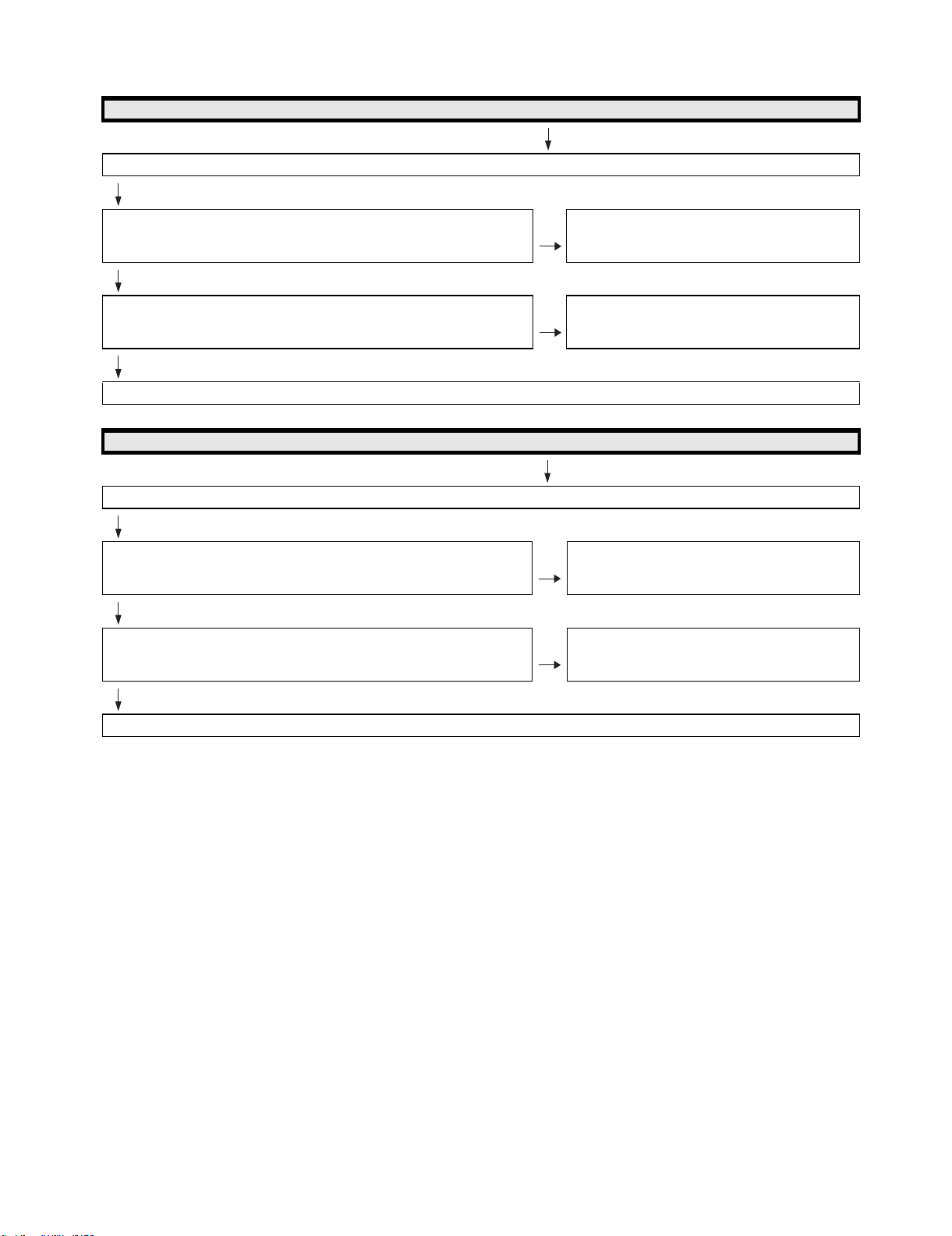
LC-60G9T / LC-70G9T
Does not the sound of the audio signal input to EXT 2 go out?
No sound from external input devices (1)
Do audio signals input to pins[7/CVBS1_IN_R, 8/CVBS1_IN_L] of EXT2(J510)?
Is CVBS_PLUG [9/CVBS1_PLUG] of J510 at "L"
YES
Do audio signals input to pins [AU36/CVBS1_AINR2, AP34/CVBS1_AINL2] of
IC3301 (Digital AV decode & Main CPU) ?
YES
Refer to “The sound is not emitted from the Speaker & Woofer though the picture has come out.”
No sound from external input devices (2)
Does not the sound of the audio signal input to EXT3 go out?
Do audio signals input to pi ns[12/COMP1_IN_R, 13/COMP1_IN_L] ofEXT3 (J510)? NO Check the setting of an external input device that con-
YES
Do audio signals input to pins[AT35/COMP1_AINR1, AT37/COMP1_AINL1] of
IC3301 (Digital AV decode & Main CPU) ?
NO Check the setting of an external input device that con-
nects with EXT2.
NO Check IC3301 and its peripheral circuits.
nects with EXT3.
NO Check IC3301 and its peripheral circuits.
YES
Refer to “The sound is not emitted from the Speaker & Woofer though the picture has come out.”
6 – 3
Page 46
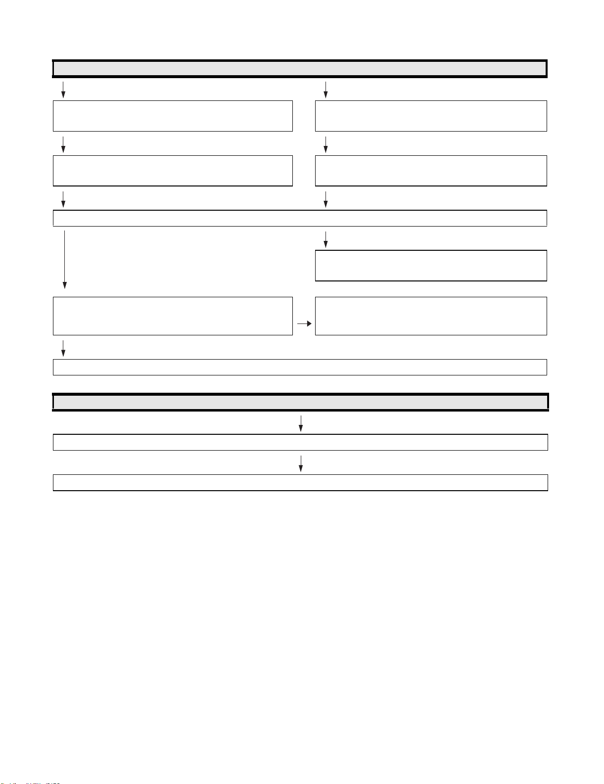
LC-60G9T / LC-70G9T
No sound from external input devices (3)
Does not the sound of the audio signal input to HDMI-2 mode go out? Does not the sound of the audio signal input to PC/Component
mode go out?
Check whether it is selected "HDMI+Analog" by the Audio select
under Menu-Setup-Option-Terminal setting-Audio select.
Check whether it is selected "Video+Audio" by the Audio select
under Menu-Setup-Option-Terminal setting-Audio select.
Do audio signals input to pins [2/PC_HDMI_L , 3/PC_HDMI_R] of J501( PC AUDIO_IN) ?
NO
Check the setting of an external input device that connects with
J501.
YES
Do audio signals input to pins[AP32/PC_HDMI_AINL4, AR33/
NO Check the line between J501 and IC3301.
PC_HDMI_AINR4] of IC3301 (Digital AV decode & Main CPU) ?
YES
Refer to “The sound is not emitted from the Speaker & Woofer though the picture has come out.”
No sound from external input devices (4)
Does not the sound of the audio signal input to HDMI1/2/3/4 go out?
Please Refer to “[External input HDMI-1/2/3/4] No picture on the display (11)”.
6 – 4
Page 47

LC-60G9T / LC-70G9T
No sound from external output device (5)
No sound from HEAD PHONE_OUTPUT/ AUDIO_OUTPUT terminal.
Does not the sound of the audio signal output to Headphone mode go
out?
Check whether it is selected "Headphone" by Headphone/Audio out
select under Menu-Setup-Option-Terminal setting-Headphone/Audio
out select.
Do audio signals output from pins [ 2/MONI_HP_R , 3/MONI_HP_L ] of J504(HP Jack/AUDIO OUT)?
Is HP_PLUG [1pin] of J504 at "H" ?
NO
Is HPOUT_MUTE at "H" ?
Is HP_MUTE [B27] of IC3301 at "H"?
Is AUDIO_MUTE(MUTE_A_ALL) [23pin] of IC2004(UCOM) at "H"?
NO
Do audio signals output from pins [ 10/MONI_HP_R, 12/MONI_HP_L ]
of IC1702(HP-AMP) ?
NO
Do audio signals input to pins [14,15] of IC1702 ? YES Check IC1702 and its peripheral circuits.
NO
Do audio signals (HP_MONITOR_L/R) output from pins
[AN34/CPU_ACO_ADAC,AN35CPU_ARO_ADAC ] of IC3301 ?
Does not the sound of the audio signal output to Audio out mode go
out?
Check whether it is selected "Audio out" by Headphone/Audio out
select under Menu-Setup-Option-Terminal setting-Headphone/
Audio out select.
YES
Check the setting of an external input device that connects with
J504.
And check the line between J504 and IC3301(Digital AV decode &
Main CPU)
YES Check the line between J504 and HPOUT_MUTE.
(Q506,Q510,IC3301 & IC2004 etc...)
YES Check the line between IC1702 and J504.
YES Check the line between IC3301 and IC1702.
NO
Check IC3301 and its peripheral circuits.
No sound from external output device (6)
No sound from DIGITAL AUDIO OUTPUT terminal.
Does audio signal output from pin[1] of sound output terminal (D527)?YES Check D527 and peripheral circuits.
NO
Does audio signal output from pin[4] of IC503 ? YES Check the line between IC503 and D527.
NO
Is AUDIO_MUTE(MUTE_A_ALL) [23pin] of IC2004(UCOM) at "H"? YES Check the peripheral circuits of IC503 and AUDIO_MUTE
NO
Does audio signal input to pin[2] of IC503 ? YES Check IC503 and peripheral circuits.
NO
Does audio signal (OPT_OUT) output from pin[AR16/OPT_OUT] of
IC3301(Digital AV decode & Main CPU) ?
NO
Check IC3301 and its peripheral circuits.
(Q505 etc...)
YES Check the line between IC3301 and IC503.
6 – 5
Page 48

LC-60G9T / LC-70G9T
No sound from external output device (7)
Does not the sound of the audio signal output to HDMI1 go out?
Does audio signal output from pin[14] of SC1501 ( HDMI1 terminal) ? YES Check SC1501 and peripheral circuits.
NO
Does audio signal output from pin[39/HECP] of IC2601(HDMI-SW) ? YES Check the line between IC2601 and SC1501.
NO
Does audio signal input to pin[36/HDMI_ARC_SPDIF] of IC2601 ? YES Check IC2601 and peripheral circuits.
NO
Does audio signal(HDMI_OPT_OUT) output from pin[Y32/
CPU_ASPDIF1] of IC3301(Digital AV decode & Main CPU)?
NO
Check IC3301 and its peripheral circuits.
YES Check the line between IC3301 and IC2601.
No picture on the display (1)
The picture doesn't appear in all modes.
Is the signal output from IC3301(DIGITAL_AV_DECODER_&_MAIN_CPU) respectively?
[VBO_TXA+-(AT4/AU4), VBO_TXB+-(AP3/AR3), VBO_TXC+-(AT2/AU2), VBO_TXD+-(AR1/AR2)]
NO
Check IC3301 and its periphe ral control circuits.
YES
Do above-mentioned signals output from connector
(SC3801) ?
YES
Similarly, is LCD controller's control signal normal ? NO Please check each control signal of DET_POW(DET_PNL12V),
YES
LCD Controller Unit:
Do signals input to connector(LW) of LCD Controller Unit ?
YES
Check the panel module.
(IC2004, IC3501, IC3502, IC3503, IC3504, X3301, etc.)
NO Check the line between IC3301 and SC3801.
PE(PNL_EN).
NO Wire harness (LV) is checked.
6 – 6
Page 49

LC-60G9T / LC-70G9T
No picture on the display (2)
Does not the picture come out when VHF/UHF is received?
(A)
Does video signal (CVBS) output from pin[9] of TUNER(TU1105) ? NO Check the tuner and its peripheral circuits.
Replace as required.
YES
Does video signal (TUNER_CVBS) input to pin [AN29/
CPU_CVBS0P] of IC3303(Digital AV decode & Main CPU) ?
YES
Refer to “No picture on the display (1)”
No picture on the display (3)
Does not the picture come out when DTV is received?
Refer to “No sound (during the reception of TV(DIGITAL) broadcasting)”
NO Check the line between TU1105 and IC3301.
(Q1106, etc...)"
No picture on the display (4)
Does not the picture of the CVBS signal input to EXT1 go out?
Does CVBS signal input to pin[5] of EXT1 (J510) ? NO Check the setting of an external input device that connects with
EXT1.
YES
Does CVBS signal input to pin [AR30/CPU_CVBS2P] of IC3301
(Digital AV decode & Main CPU)
YES
Refer to “o picture on the display (1)”
NO Check the line between SC505 and IC3301.
6 – 7
Page 50

[External input EXT2] No picture o n the d isplay (5)
Does not the picture of the CVBS signal input to EXT2 go out?
LC-60G9T / LC-70G9T
Does CVBS signal input to pin[10] of EXT2 (J510) ?
Is CVBS_PLUG [9/CVBS1_PLUG] of J501 at "L" ?
YES
Does CVBS signal input to pin [AR31/CPU_CVBS1P] of IC3301
(Digital AV decode & Main CPU) ?
YES
Refer to “No picture on the display (1)”
[ExternalinputEXT3]Nopictureonthedisplay(6)
Does not the picture of the COMPONENT signal input to EXT3 go out?
Do COMPONENT signals input to pins [18/COMP1_Y, 15/
COMP1_Pr, 16/COMP1_Pb] of EXT3 (J510) ?
YES
Do COMPONENT signals input to pins [AU26/COMP_Y1P), (AP26/
COMP_PR1P) and (AR26/COMP_PB1P] of IC3301 (Digital AV
decode & Main CPU) ?
YES
Refer to “No picture on the display (1)”
[External input PC] No picture on the display (7)
NO Check the setting of an external input device that connects with
EXT2.
NO Check the line between J510 and IC3301.
NO Check the setting of an exter nal input device that connects with
EXT3.
NO Check the line between J510 and IC3301.
Does not the picture of the ANALOG-RGB signal input to PC_IN (15pin-D-SUB terminal) go out?
Do ANAL OG-RGB and synchronized signal input to pin
[(1, 2, 3)/(PC_RED, GREEN, BLUE), (14 and 13)/(PC_VSYNC,
H.Sync) ] of PC_IN (SC501) ?
YES
Do ANALOG-RGB and synchronized signal input to pins [AR25/
PC_RP, AR24/PC_GP, AU24/PC_BP, and AN25/PC_HSYNC,
AM25/PC_VSYNC] of IC3301 (Digital AV decode & Main CPU) ?
YES
Refer to “No picture on the display (1)”
NO Check the connection and setup with the external PC_IN devices.
NO Check the line between SC501 and IC3301.
6 – 8
Page 51

LC-60G9T / LC-70G9T
[External input HDMI-1/2/3/4] No picture on the display (8)
Does not the picture/sound of the HDMI signal input to HDMI-1/2/3/4 go out?
Is the Hot plug detection function output from pin [19] of the HDMI1(SC1501) normal ?
Is the Hot plug detection function output from pin [19] of the HDMI2(SC1502) normal ?
Is the Hot plug detection function output from pin [19] of the HDMI3(SC1503) normal ?
Is the Hot plug detection function output from pin [19] of the HDMI4(SC1504) normal ?
YES
Is EDID data pins[58/HDMI1_SCL, 57/HDMI1_SDA] of IC2601accessed,
and is it read from pins[15, 16] of a HDMI-1(SC1501) ?
Is EDID data pins[73/HDMI2_SCL, 72/HDMI2_SDA] of IC2601 accessed,
and is it read from pins[15, 1 6] of a HDMI-2(SC1502) ?
Is EDID data pins[54/HDMI3_SCL, 53/HDMI3_SDA] of IC2601 accessed,
and is it read from pins[15, 1 6] of a HDMI-3(SC1503) ?
Is EDID data pins[49/HDMI4_SCL, 48/HDMI4_SDA] of IC2601 accessed,
and is it read from pins[15, 1 6] of a HDMI-4(SC1504) ?
YES
Do TMDS signals input to pins [26&27/HDMI1_CLKNP, 28&29/
HDMI1_D0NP, 30&31/HDMI1_D1NP, 32&33/HDMI1_D2NP] of IC2601 ?
NO Check the line between SC1501 and pin[59] of IC2601(HDMI-
SW).
NO Check the line between SC1502 and pin[74] of IC2601(HDMI-
SW).
NO Check the line between SC1503 and pin[55] of IC2601(HDMI-
SW).
NO Check the line between SC1504 and pin[50] of IC2601(HDMI-
SW).
NO
Check the setting of an external input device that connects
with HDMI-1/2/3/4.
NO Is access possible in the exchange of IC2601 ?
NO
Check the peripheral circuit of SC1501/1502/1503/1504 and
IC2601.
NO Check the line between HDMI-1(SC1501) and IC2601.
Do TMDS signals input to pins [17&18/HDMI2_CLKNP, 19&20/
HDMI2_D0NP, 21&22/HDMI2_D1NP, 23&24/HDMI2_D2NP] of IC2601 ?
Do TMDS signals input to pins [8&9/HDMI3_CLKNP, 10&11/HDMI3_D0NP,
12&13/HDMI3_D1NP, 14&15/HDMI3_D2NP] of IC2601 ?
Do TMDS signals input to pins [99&100/HDMI4_CLKNP, 1&2/
HDMI4_D0NP, 3&4/HDMI4_D1NP, 5&6/HDMI4_D2NP] of IC2601 ?
YES
Do TMDS signals output from pins [87&86/HDMI0_RX_CLKNP_, 85&84/
HDMI0_RX_D0NP_, 83&82/HDMI0_RX_D1NP_, 81&80/
HDMI0_RX_D2NP] of IC2601 respectively.
YES
Do TMDS signals input to pins [AH34&AH35/HDMI0_RX_CLKNP ,
AG34&AG35/HDMI0_RX_D0NP , AG36&AG37/HDMI0_RX_D1NP ,
AF34&AF35/HDMI0_RX_D2NP] of IC3301 (Digital AV decode & Main
CPU)?
YES
Refer to “Refer to “No picture on the display (1)” or “The sound is not emitted from the Speaker & Woofer though the picture has come out.”
NO Check the line between HDMI-2(SC1502) and IC2601.
NO Check the line between HDMI-3(SC1503) and IC2601.
NO Check the line between HDMI-4(SC1504) and IC2601.
NO Check the IC2601 and peripheral circuits.
NO Check the line between IC3301 and IC2601.
6 – 9
Page 52

Does not the signal input to Network go out?
LC-60G9T / LC-70G9T
[External input Network] No picture on the display
Does the signal in/output to pins(1),(2),(3),(6) of LAN-jack
(J9401)?
NO Check the interface device and peripheral circuits.
(power-LED of hub, LINK-LED of hub)
YES
Do signals in/output to pins of IC3301 (Digital AV decode & Main
CPU)?
NO Check the line between IC3301 and J9401.
(T9401 etc)
Pins [AU18&AT18/CPU_DATMDI_RJ45_TNP, AU17&AT17/
CPU_DATMDI_RJ45_RNP]
YES
Check IC3301 and its peripheral circuits.
No power ( No LED light up ) or No startup ( LED RED Blinking )
Is the AC cord connector tightly connected to the set? NO Reconnect the AC cord tightly and turn on the power again.
YES
Are the wire harnesses and other cables properly connected to
the set?
YES
Is power supplied from pins [15/BU+5V] of [PD]P3801 ? NO Replace the power unit.
YES
Is there the pins [14/PS_ON] of [PD]P3801 at “H”? NO Check the signal line between PS_ON and IC2004(UCOM)/
NO Reconnect the wire harnesses and other cables properly to the set.
IC3301(Digital AV decode & Main CPU) .
YES
Is there the pins [13/AC_DET] of [PD]P3801 at "H"? NO Check the power unit ,
YES
Is power supplied from pins [5~8/UR+13V] of [PD]P3801 as
specified?
YES
Are the DC/DC converter outputs and the output voltages along NO Check the DC/DC converters and the control lines.
1) BU3.3V (IC9605 etc.)
2) D5V (IC9607 etc.)
3) U5V (IC9607 etc.)
4) D3.3V (IC9606 etc.)
5) M2.3V (IC9601 etc.)
6) D1.5V (IC9604 etc.)
7) D1.2V (IC9603 etc.)
8) AT5V (IC1104 etc.)
9) TE+1.2V (IC1102 etc.)
10) IF+1.8V (IC1109 etc.)
11) SAT+1.2V (IC1102 etc.)
12) STB+3.3V (Q9602 etc.)
13) AVDD12_HDMISW (IC2602)
14) CPU_ADAC+3.3V (IC3303 etc.)
(IC3302 etc...)
(IC3105 etc...)
(IC1903 etc...)
and the signal line between AC_DET and IC2004/IC3301.
NO Check the line between PS_ON and IC2004/IC3301 .
Replace defective parts as required.
6 – 10
Page 53

LC-60G9T / LC-70G9T
No light (Back Light doesn't light)
Is the AC cord connector tightly connected to the set? NO Reconnect the AC cord tightly and turn on the power again.
YES
Are the wire harnesses and other cables properly connected in
the set?
YES
Does Power starts up (LED Turn Green) ? NO Refer to "No power ( NO LED Light up ) or no startup
YES
Is there the pins [16/PNL_POW] of [PD]P3801 at "H"? NO Check the power unit ,
YES
Is there the pins [24/STB] of [PD]P3801 at "H"? NO Check the power unit ,
YES
Replace the power unit.
NO Reconnect the wire harnesses and other cables properly in the set.
(LED Red blinking ) "
and the signal line between PNL_POW and IC3301
(Digital AV decode & Main CPU) .
and the signal line between STB and IC2004(UCOM)/IC3301 .
Does a single or several vertical stripes
appear on the LCD
screen?
Replace the LCD panel or the power unit.
The backlight functions.
Does not the image come
out in the LCD screen
(screen black) ?
Replace the LCD_CONT_UNIT.
Does a single or several horizontal stripes
appear on the LCD
screen?
Does the entire LCD
screen look whitish all
over?
LCD Panel failure(1)
Do luminescent or
black dots appear on
the screen?
LCD Pa nel failure(2)
Does the QS drive func-
tion?
Is the on-screen image
rippling or distorted?
Are the data bit drop-out?
(No solution even when
turning on and off the QS
drive)
Is there any portion which some
screens were
darkish or became
whitish?
Is the gamma correction as
specified?
Does all LED of
one line are not
lighting?
6 – 11
Page 54

LC-60G9T / LC-70G9T
CHAPTER 7. MAJOR IC INFORMA-
TIONS
[1] MAJOR IC INFORMATIONS
[1] MAJOR IC INFORMATIONS
1. MAJOR IC INFORMATIONS
1.1. IC2601 (VHiSii9387A-1Q)
This IC is 5 input and 1 output HDMI port processor.
The TMDS cores run at 2.25Gbps. (Supports video resolutions up to 1080p, 60Hz, 12bit.)
The adaptive equalizer provides long cable support.
This IC has been pre-programmed with HDCP keys.
EDID and DDC support for 5 HDMI/DVI ports and 1 VGA port. (This IC includes 512-byte NVRAM and 256-byte SRAM for 5 HDMI ports and 128-byte
SRAM for VGA port.)
This IC supports the mandatory and several optional 3D formats described in the HDMI 1.4 Specification.
“Audio Return Channel” and “HDMI Ethernet C hannel” support for one receiver port.
“MHL” support for resolutions up to 1080i@60Hz can be assigned to any one input port.
When changing this IC, please write EDID (how to write EDID is shown in Chapter 5 and section 10.1).
1.2. IC2004 (RH-iXD515WJN7Q)
The monitor microprocessor is intended to communicate with the main microprocessor and to operate the system.
It also controls power of the entire system.
1.3. IC1901, IC1902 (VHiYDA176DL-1Y)
The Class-D type digital audio power amplifier YDA164EZ gives maximum continuous output of 10 W/ch or woofer output 15W.
1.4. IC3301 (RH-iXD414WJN2Q)
This LSI is FULL HIGH -DEFINITION 1080P DIGITAL TV SYSTEM-ON-A-CHIP.
It combines a transport de-multiplexer, a high definition video decoder, an AC3 audio decoder, a four-link LVDS transmitter, a V-by-One transmitter,
and an NTSC/PAL/SECAM TV decoder with a 3D comb filter (NTSC/PAL).
It supports Full-HD MPEG1/2/4/H.264/DiviX/VC1/RM/AVS/VP6/VP8 video decoder standards, and JPEG.
Audio support includes a BTSC and a Dolby AC3/MPEG-2 Layer 1, 2, audio decoder.
Two SPDIF output and a pair of analog outputs (L-R) are provided.
The LSI incorporates a complete ARM Cortex-A9 dual core based microprocessor subsystem including caches with bridging to memory and a local
bus, where external peripherals can be attached.
Integrated peripherals include four USB 2.0, three UARTs, counter/timers and GPIO controllers.
It supports ATSC/DVB-T/DVB-C demodulators.
1.5. IC3501, IC3502 (RH-iXD555WJQZQ)
These are 2G-bit (128M x 16bit) DDR3-1600 synchronous DRAM.
1.6. IC3503, IC3504 (RH-iXD555WJQZQ)
These are 2G-bit (128M x 16bit) DDR3-1600 synchronous DRAM.
1.7. IC3103 (RH-iXD584WJQZQ)
The 4G-bit NAND flash memory device stores the main CPU program.
1.8. IC3104 (VHiRV2464Ai-1Y)
This is 64k-bit EEPROM device including the user setting.
1.9. IC2007 (VHiRV2402Ai-1Y)
This is 2k-bit EEPROM device stores the nomitor microprocessor setting.
1.10. IC506 (VHiM3221EiP-1Y)
This IC is a high speed, single-channel RS-232 transceiver interface device that operates from a single 3.3V power supply.
The device provides the electrical interface between an asynchronous communication controller and the serial-port connector.
This device operate at data signaling rates up to 460kbit/s.
All RS-232 (Tout and Rin) and CMOS (Tin and Rout) inputs and outputs are protected against electrostatic discharge (up to +/- 15kV ESD protection).
7 – 1
Page 55

LC-60G9T / LC-70G9T
1.11. IC1702 (VHiMAX 97220 -1Y)
This IC is audio amplifier for line-out/head-phone.
1.12. IC1703 (VHiYSS952QZ-1Y)
Audio DSP (YSS952QZ) has digital audio adjustment function (for example, PEQ, bass/treble, b alance, bass enhancer, etc.) and adjusts TVs audio
quality.
7 – 2
Page 56

CHAPTER 8. OVERALL WIRING /
BLOCK DIAGRAM
[1] SYSTEM BLOCK DIAGRAM
LC-60G9T / LC-70G9T
8 – 1
Page 57

LC-60G9T / LC-70G9T
8 – 2
Page 58

[2] OVERALL WIRING DIAGRAM
M
AIN
39
0
24.576MHz
2
3
DET
20
EEPROM
4
+1 8V
f
AMP(0
1CH)
AMP
DATA
SW
EXT
AUDIO MUTE
AUDIO MUTE
IC2004
T2 TS CLK/SYNC/VAL/D0
D7
AC DET
/
N SRESET
I/O
/
8
M
DEMOD TSCLK/SYNC/VAL/DATA0
7
23V
V
TUNER I2C
C
ERR
I/O
I/O
P
RC CPU
GND
2
1
OFL2
S lit
_
IC1102
MT5396(FHD)
X3301
E
Di
git
al
3
3V
MAIN
OPT OUT
000MH
3
_
3
8
05
DDR3(1333M)
_
14
,
E
P
UART CPUTO232C UART 232CTOCPU
N
L
O
IC503
IN
L/R
U
1
1
1
T
K
13
S
_
N
M
R
B
kU
8
RGB
H
D
MI 2
O
O
R
PC
R/G/B
R
R
U
S
S
Q
+1
2V
DDC
3
Disclete
PowerSW
5V
0.5A
WAKEUP
MHL
WAKEUP
USB D2P/N
+5V
U5V
㓄⨨
J9
4
01
T-CON
1 (41p)
3
7
7
18
202122
40
39
VBO_LOCKN
VBO_LOCKN
19
PE_T
_
_
2_3_DET
ODD_EVEN
I2C_READY
FILM_VIDEO
FILM_VIDEO
PNL_EN_T
࠙LVࠚSC3801 (
1
6
12
OFL1_FRCRST
PNL_WP
4
489
2
17
16
10/11
10/11
L/R_REF
VSYNC
VSYNC
DET_POW_T
I/O
I/O
I/O
I/O
BU+3.3V
IC2004
RESET
MODE
3
0
20
C
Reset
I
UCOM_RST
UCOM_MODE
Thermister
HP_MUTE
N_PER_RST
N_AMP_PROTECT
SP_MUTE
SP_MUTE
AUDIO_MUTE
+3.3V
EEPROM
IC3104
IC3104
5
C
C/36
8
R
1
00
2
X
32.768kHz
GSP_PWM1
PWM2
EEPROM_SCL/SDA
I2C
IXD241WJ
1
00
2
L
tal
F
X
20MHz
Mute
BU+3.3V
7
IC200
WP
SUB MCU
Xtal
circuit
LC-60G9T / LC-70G9T
nit
U
ER
OW
P
P3802(4p)
࠙PLࠚPNL12V P380
23
22
24
17
PNL_12V
PNL
.
+3.3V
+
BU+3.3V
PS_ON
2kbit
EEPROM
_
STB
STB
AC_DET
LAMP_ERR
SMPOW
O
I/O
I/O
I/O
I/O
I
I2C
A/D
PWM
UART
I/O
UART
I/O
I/O
I/O
I/O
PM_REQ
N_SRESET
SMPOWHOLD
N_MUTE_A_ALL
HDMI_CEC_IN
HDMI_CEC_OUT
CPU_TXD1_UCOM,CPU_RXD1_UCOM
CPU_TXD1_UCOM,CPU_RXD1_UCOM
+5V
+2.3V
IC3302
IC3303
+1.2V
+3.3V
+3.3V
+1.1V
+1.5V
VbyOne OUT
CVBS
Component
CVBS_Out
N_TUN_RST
CPU_ANT_POW
DEMOD_TSCLK/SYNC/VAL/DATA0-7
VON
08
0
IC2
C
RC,OPC
IR_PASS
RC
GND
0
0
1
t
Select
2009
-3
IC2002-3
C
I
THERMO
NTUNT2RST
STB_CPU
OFL1
OFL1
RC_CPU
I/O
IC3303
MT5396(FHD)
I2C_0
I2C_1
TUNER_I2C
RGB in
RGB HV
DDC_I2C_1
DDC_I2C_1
PC_R/G/B
(400KHz 3.3V)
(400KHz 3.3V)
(100KHz 3.3V)I2C_1
(400KHz 3.3V)
PC_VSYNC/HSYNC
I2C_0
TU_DEMOD_SCL/SDA
TU_DEMOD_SCL/SDA
R P3801(24p)
21
21
19
IC3802
IC3802
Spliter
AC_DET
OFL2
PWM_0
PWM_0
PWM_1
࠙PDࠚPOWER P
13
14
18/20
+3.3V
05
8
iter
3
pl
IC
Spliter
S
z
.
X3301
27.000MHz
PNL_POW
16
UR+13V
A
AC_DET
PS_ON
PNL_POW
P
U+5V
MAIN
CPU(KEY2)
OPC
UP
MHL_DET_POW
PNL_I2C_EN
33M)
3
2Gbit
(1
IC3501
C3502
3
2Gbit
I
DDR3(1333M)
DR
IC3503
IC3503
D
+1.5V
DDR3(1333M)
+1.5V
+1.5V
+1.5V
-
H.264 / VC-1
DigitalAVdecode&MainCPU
Audio out
Audio in
Audio in
HDMI_1
HDMI_1
I2S(SDATA/LRCK/SCLK)
(DATA)
SIF
_
_
SIF
PC/HDMI_LR
COMP_IN_L/R
COMP_IN_L/R
CVBS2_IN_L/R
CVBS1_IN_L/R
HP/MONI_L/R(PWM)
LED_Drive
BU+5V
R/C
C
OPC
p
BU+3.3V
BU+3.3V
D+5V
D+3.3V
D+1.5V
D+1.2V
ac
POWER CIRCUIT
BackUp
B_CPU(KEY1),SDA_STB_CPU(
SCL_STB_CP
EEP,LED_G,LED_R,LED_OPC
LED_SLEEP,
W/REQ
POW_SW/RE
PC
RC,OPC
LSE
LR_PULSE
ANOTHER_WAKEUP
UCOM_MHL_CBUS, MHL
M)
33
13
(
IC3504
DDR3
Select
BU+3.3V
BU+3.3V
IC2002-2
ONDA6㹼13
0
1
ONDD8㹼15
SDI0㹼
SDI0
SDIOCMD/SDIOCLK
SDIO
USB_2
US
U
USB_1
USB_0
U
UART-2
U
UART-TXD1
UA
UA
UART-RXD1
UART-TXD0
UA
UART-RXD0
UA
IC2001
/eM
/eMMC
/NAND Flash
/NA
+3.3V
SPI_FLASH
SPI
1
0
Select
IC2002-1
DTV/SPDIF
RESET
BU+3.3V
BU+3.3V
OPT_OUT
HDMI_ARC
IC3102
ORESET#
(400KHz)
I2C_1
N_SRESET
SMPOWHOLD
SMPOWHOLD
+3.3V
2Gbit
IC3103
NAND FLASH
BU+3.3V
UR13V
BU+3.3V
BU+3.3V
HDMI_CEC_IN
HDMI_CEC_OUT
er
ff
Bu
IC2005
LVC125AN
R/
࠙RAࠚP103(9p)
P2001(15p)
Cࠚ
R
࠙
ࠚP151(4p)
K
T
TACT KEY
࠙
3D IR
࠙IRࠚ(3p)
01
4
J9
Ethernet
Ethernet
+2.3V
IC2602
.
+1.2V
+3.3V
+5V
IC1504
HDMI-SW
SII9387A
DDC_1
HDMI_1
5396W) 1J㸧
T
work
M
t
(
X
0
AIN
M
K Diagram㸦LE95
264 / VC-1 / HDMI-1.4 / Ne
C
.
O
BL
D / H
3
FHD SYSTEM
CVBS2_IN_L/R
CVBS1_IN_L/R
CVBS1_IN
CVBS1_IN
CVBS2_IN
R
L
LR
CVBS
CVBS
CVBS
UT
P
7
PUT
PUT
6
N
N
IN
I
I
+3.3V
3
I2C_0(400KHz)
DSP
YSS952
IC170
03
+1.8V
24.576MHz
_
19
X1701 Xtal
+13V
COMP1_IN_L/R
COMP1_Y/Pb/Pr
䛇
P
LR
䛆S
mponent
o
C
T
5
NPU
I
IC
_
AMP_DATA_LR
AMP_DATA_SW
AMP_LRCK/BCLK/MCLK
+13V
.
YDA176
YDA176
YDA176
IC1902
IC1901
er
SP AMP(2CH)
oo
Woofer AMP(0.1CH)
4
䛇
-
190
1903
䛆SP
P
P
EXT-SP
EXT-SP
r
ER
K
EA
P
Woofe
S
AUDIO_MUTE
N_PER_RST
N_AMP_PROTECT
+2.3V
+2.3V
1109
C
I
N_TUN_T2_RST
N_TUN_RST
SIF
SIF
T2_TS_CLK/SYNC/VAL/D0-D7
AMP_MUTE
AMP_
CI_CE1/OE/WE/A0-A14/D0-D7
TS_CIIN_CLK/SYNC/VAL/D0-D7
TS_CIOUT_CLK/SYNC/VAL/D0-D7
CVBS
+5V
d
I Car
C
+1.8V
N
I
RF
HP_MUTE
AUDIO_MUTE
N_PER_RST
+13V
+2.3V
+2.3V
IC1102
IC1104
+1.2V
+1.2V
ANT+5V
+3.3V
er
er
al
105
un
un
1
git
TU
Analog/
Di
Si T
Si T
704
C2
HP-AMP
I
OPT_OUT
AUDIO_MUTE
AUDIO_MUTE
AUDIO_MUTE
+5V
+5V
+5V
Disclete
IC503
HP/MONI_L/R
)
g
u
l
P
dio Out
ni
u
i
OPTICAL
A
(M
_
PC_VSYNC/HSYNC
PC_R/G/B
PC/HDMI_LR
I
M
T
T
U
U
SUB
O
O
udio
-
RGB
A
D
RGB/HD
8
2/8
INPUT
INPUT
8 – 3
DDC_1
DDC_0
HDMI_0
DDC_2
HDMI_2
U5V
UART_CPUTO232C,UART_232CTOCPU
ugh
o
r
h
sst
a
P
RC
IC506
RS232C TxRx
+3.3V
o.9 pin
N
232C
I 1
M
RS
HD
INPUT
IC1507
+5V
Disclete
I)
MI 2
DV
D
(
(ARC)
HDMI 3
H
UT
UT
P
P
2
1
3
IN
IN
INPUT
_
HDMI_CEC
ANOTHER_WAKEUP
_
DDC_3
HDMI_3
HDMI_3
_
PowerSW
MHL_WAKEUP
UCOM_MHL_CBUS, MHL_DET_POW
EN_RPWR4_N,EN_VBUS4,VBUS4_OC,MHL_DET
HDMI_CEC
USB_D0P/N
(MHL)
(MHL)
HDMI 4
HDMI 4
4
4
INPUT
INPUT
J9502
U5V
U5V
U5V
W
W
SW
r
IC9502
IC9501
IC9503
IC9503
Powe
PowerSW
PowerS
PowerS
+5V
+
+5V
B
US
Side
1.5A
0.5A
0.5A
USB_D2P/N
USB_D1P/N
USB_D3P/N
USB
USB
J9503
J9501
㓄⨨
ୗഃ
HDD⏝
D࣮࢝ࢻ
S
Page 59

LC-60G9T / LC-70G9T
AIN
0
24.576MHz
2
3
DET
4
+1 8V
f
AMP(0
1CH)
DATA
SW
AUDIO MUTE
IC200
4
AC DET
/
N SRESET
/
M
23V
V
C
LAMP
ERR
I/O
P
RC CPU
GND
2
H.2
6
4 / VC
S lit
_
X3301
E
U
D
igital
3
3V
_
OPT OUT
000MH
3
_
IC3805
DDR3(1333M)
_
14
,
E
P
N
L
O
IN
L/R
U
1
T
K
13
S
_
N
M
R
B
kU
HDMI
2
O
O
R
PC
R/G/B
R
R
U
S
S
Q
2V
02
DDC
3
Disclete
P
ow
e
r
S
W
5V
WAKEUP
WAKEUP
USB D2P/N
㓄⨨
J9401
T-CON
3
7
7
18
202122
40
39
VBO_LOCKN
VBO_LOCKN
19
1
6
PE_T
_
_
2_3_DET
ODD_EVEN
I2C_READY
FILM_VIDEO
FILM_VIDEO
PNL_EN_T
PNL_WP
e
Unit
R
OWE
P
P3802(4p)
1 (41p)
࠙LVࠚSC3801 (
12
10/11
10/11
OFL1_FRCRST
BU+3.3V
5
4
489
2
17
16
GSP_PWM1
PWM2
M
BU+3.3V
2kbit
IC2007EEPRO
L/R_REF
VSYNC
VSYNC
DET_POW_T
WP
EEPROM_SCL/SDA
O
I/O
I/O
I2C
I/O
I/O
I
4
SUB MCU
IC200
R8C/36C
IXD241WJ
RESET
MODE
Reset
IC2003
UCOM_RST
UCOM_MODE
Thermister
HP_MUTE
N_PER_RST
N_AMP_PROTECT
+3.3V
EEPROM
IC3104
IC3104
I/O
1
PM_REQ
l
00
ta
2
X
tal
FL
X
X2001
20MHz
32.768kHz
Mute
circuit
+3.3V
+1.5V
BU+3.3V
CVBS
CVBS_Out
SP_MUTE
SP_MUTE
AUDIO_MUTE
࠙PLࠚPNL12V P380
22
24
23
17
PNL_12V
PNL
.
+3.3V
+
PS_ON
_
STB
STB
AC_DET
LAMP_ERR
SMPOW
I/O
I/O
I/O
I/O
I2C
A/D
PWM
I/O
UART
UART
I/O
I/O
I/O
N_SRESET
SMPOWHOLD
N_MUTE_A_ALL
HDMI_CEC_IN
HDMI_CEC_OUT
CPU_TXD1_UCOM,CPU_RXD1_UCOM
CPU_TXD1_UCOM,CPU_RXD1_UCOM
+2.3V
+5V
C3302
IC3303
I
+1.2V
+3.3V
+1.1V
VbyOne OUT
Component
N_TUN_RST
VON
08
20
C
I
C
RC,OPC
IR_PASS
RC
GND
0
0
1
t
Select
-3
IC2002-3
IC2009
THERMO
D_IF-/+
STB_CPU
OFL1
OFL1
RC_CPU
I/O
3
0
3
IC3
MT5396(FHD)
I2C_1
TUNER_I2C
I2C_0
RGB HV
RGB in
DDC_I2C_1
DDC_I2C_1
PC_R/G/B
(100KHz 3.3V)I2C_1
(400KHz 3.3V)
(400KHz 3.3V)
(400KHz 3.3V)
PC_VSYNC/HSYNC
I2C_0
TU_DEMOD_SCL/SDA
TU_DEMOD_SCL/SDA
R P3801(24p)
21
21
19
IC3802
IC3802
Spliter
AC_DET
OFL2
PWM_0
PWM_1
PWM_0
-
C-1
V
4 /
6
H.2
Digital AV decode & Main CPU
HDMI_1
HDMI_1
I2S(SDATA/LRCK/SCLK)
(DATA)
࠙PDࠚPOWER P
13
14
18/20
+3.3V
IC3805
Spliter
Spliter
z
.
X3301
27.000MHz
PNL_POW
16
UR+13V
A
AC_DET
PS_ON
PNL_POW
P
U+5V
D+5V
MAIN
CPU(KEY2)
OPC
UP
MHL_DET_POW
PNL_I2C_EN
1
33M)
3
50
(1
C3
3
2Gbit
I
2Gbit
IC3502
DDR
IC3503
IC3503
IC3504
DDR3(1333M)
+1.5V
DDR3(1333M)
+1.5V
+1.5V
+1.5V
Audio out
Audio in
Audio in
SIF
_
_
OPT_OUT
PC/HDMI_LR
COMP_IN_L/R
COMP_IN_L/R
CVBS2_IN_L/R
CVBS1_IN_L/R
HP/MONI_L/R(PWM)
v
Dri
D_
LE
BU+5V
R/C
OPC
p
BU+3.3V
BU+3.3V
D+3.3V
D+1.5V
D+1.2V
ac
POWER CIRCUIT
BackUp
B_CPU(KEY1),SDA_STB_CPU(
SCL_STB_CP
EEP,LED_G,LED_R,LED_OPC
LED_SLEEP,
W/REQ
POW_SW/RE
PC
RC,OPC
LSE
LR_PULSE
ANOTHER_WAKEUP
UCOM_MHL_CBUS, MHL
DDR3(1333M)
Select
BU+3.3V
BU+3.3V
IC2002-2
ONDA6㹼13
0
1
ONDD8㹼15
SDI0
SDI0㹼
SDIO
SDIOCMD/SDIOCLK
US
USB_2
U
USB_1
USB_0
U
UART-2
U
UA
UART-TXD1
UA
UART-RXD1
UART-TXD0
UA
UART-RXD0
UA
IC2001
/eM
/eMMC
/NAND Flash
/NA
+3.3V
SPI_FLASH
SPI
1
0
Select
IC2002-1
DTV/SPDIF
RESET
BU+3.3V
BU+3.3V
IC3102
ORESET#
HDMI_ARC
(400KHz)
I2C_1
N_SRESET
SMPOWHOLD
SMPOWHOLD
+3.3V
H
LAS
F
2Gbit
IC3103
ND
A
N
BU+3.3V
UR13V
BU+3.3V
BU+3.3V
HDMI_CEC_IN
HDMI_CEC_OUT
5
00
2
IC
Buffer
LVC125AN
R/C
࠙RAࠚP103(9p)
࠙RCࠚP2001(15p)
TACT KEY
࠙TKࠚP151(4p)
3D IR
࠙IRࠚ(3p)
J9401
Ethernet
Ethernet
+2.3V
02
IC26
.
+1.2V
+3.3V
+5V
IC1504
HDMI-SW
SII9387A
DDC_1
DDC_1
HDMI_1
DDC_0
HDMI_0
DDC_2
work
t
AIN
M
I-1.4 / Ne
M
HD
/
264 / VC-1
.
D / H
3
FHD SYSTEM BLOCK Diagram㸦G9T(MT5396W) 1J㸧
CVBS2_IN_L/R
CVBS1_IN_L/R
CVBS1_IN
CVBS1_IN
CVBS2_IN
R
BS
L
LR
V
CVBS
CVBS
C
7
PUT
PUT
6
N
N
INPUT
I
I
+3.3V
I2C_0(400KHz)
DSP
C1703
YSS952
I
24.576MHz
COMP1_IN_L/R
COMP1_Y/Pb/Pr
t
n
LR
pone
m
Co
T
5
NPU
I
+1.8V
_
X1701 Xtal
+13V
IC1902
䛇
1903
䛆SP
P
KER
A
SPE
IC1903
_
AMP_DATA_LR
AMP_DATA_SW
AMP_LRCK/BCLK/MCLK
+13V
.
01
9
1
YDA176
YDA176
YDA176
IC
er
SP AMP(2CH)
oo
Woofer AMP(0.1CH)
-
P䛇
S
1904
䛆
P
EXT-SP
EXT-SP
r
AUDIO_MUTE
N_AMP_PROTECT
N_PER_RST
+2.3V
D_IF-/+
AMP_MUTE
AMP_
N_TUN_RST
Woofe
+3.3V
N
I
RF
+2.3V
9
IC110
+1.8V
3
0
1
igital
TU1
Analog/
D
8 – 4
HP_MUTE
H
AUDIO_MUTE
A
N_PER_RST
N
4
0
7
C2
HP-AMP
I
OPT_OUT
AUDIO_MUTE
AUDIO_MUTE
AUDIO_MUTE
+5V
+5V
+5V
Disclete
IC503
Si Tuner
Si Tuner
HP/MONI_L/R
OUT
OUT
OPTICAL
Audio Out
(Mini Plug)
UART_CPUTO232C,UART_232CTOCPU
h
IC506
RS232C TxRx
pin RC Passthroug
9
_
+3.3V
PC/HDMI_LR
PC_VSYNC/HSYNC
PC_R/G/B
No.
I
HDM
RGB/
PUT
C
232
udio
RGB
-
A
D-SUB
S
R
2/8
INPUT8IN
HDMI_2
U5V
507
1
IC
+5V
Disclete
2
I)
V
(D
(ARC)
HDMI
HDMI 3
HDMI 1
UT
2
P
1
3
N
INPUT
INPUT
I
INPUT
_
HDMI_CEC
ANOTHER_WAKEUP
_
HDMI_3
DDC_3
HDMI_3
rSW
_
we
Po
MHL_WAKEUP
UCOM_MHL_CBUS, MHL_DET_POW
EN_RPWR4_N,EN_VBUS4,VBUS4_OC,MHL_DET
HDMI_CEC
HL)
HL)
M
M
(
(
HDMI 4
HDMI 4
4
4
INPUT
INPUT
USB_D0P/N
J9502
U5V
U5V
U5V
W
3
3
50
50
9502
9
9
werS
C
C
owerSW
owerSW
owerSW
IC
IC9501
I
I
Po
P
P
P
+5V
+
+5V
USB
Side
1.5A
0.5A
0.5A
USB_D2P/N
USB_D1P/N
USB_D3P/N
3
50
SB
USB
U
J9
J9501
㓄⨨
ୗഃ
HDD⏝
D࣮࢝ࢻ
S
Page 60
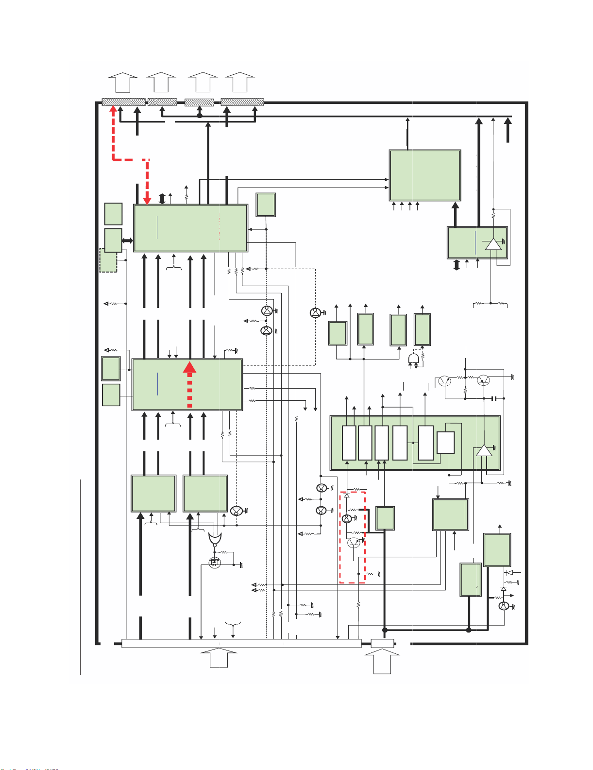
LC-60G9T / LC-70G9T
0xE8
I2C
,
,
,
,
y
,
THCV216
4
,
,
,
I2C
10
THCV216
1
8V
y
4
10
_
_
VCC 1.1V
Step
V
OFL
BD8125MU
VCC
1.1V
Step
,
,
,
,
BD8125MU
Q
VLS 15 6V
VLS
15
6V
To
Panel
CN5301
SC5301
80pin
WP
SCK
CS
SDO
SDI
64pin
Mini LVDS 8bit 7pair
24MHz
IC5801
Primrose
8Mb
FLASH
16Mb
FLASH
10k
10k
Ach
ROM_WP
]
PST8429U
Reset IC
[
Daphne
27MHz
HX6518-A
IC5103
Ach
LVDS 10bit 6pair
VbyOneRx
VCC_3.3V_A
One HS 10bit
b
Bch
Ach
SC4802
41pin
*3ULPURVH'DSKQHكT&21ഝ%ORFN
To
Panel
(to Daphne or Main)
PWM1,PWM2
DAC
=
4Ⰽኚ
SubPixel
Rendering
VCC_3.3V
VCC_2.5V
Bch
LVDS 10bit 6pair
PWM1,PWM2 (from Primrose)
LR_OUT (from Primrose)
LED BLไᚚ
SD㧗⏬㉁ᅇ㊰
Fred Lightᑐᛂ
Bch
VCC_3.3V_Daphne
VCC_1.2V_Daphne
PDN
LOCKN
.
_
CN5302
64pin
LR_OUT (to Daphne or Main)
TCN_CS1䡚12
100䃈
QS,GHOST⿵ṇ
䜺䞁䝬⿵ṇ( ᗘ)
VCC_1.1V
Cch
ᮍ⏝䛿
Cch
LVDS 10bit 6pair
VbyOneRx
VCC_3.3V_A
One HS 10bit
b
Cch,Dch
LOCKN
To
Panel
LS
GOE
GCK
GSP
SBR, MPD
4Ⰽ୪䜃᭰䛘
䜽䝻䝇䝖䞊䜽⿵ṇ
READY
Dch
LVDS 10bit 6pair
TCON READY
⤒㊰Through
ྍ⬟䛻PCBᑐᛂ
SDA
Dch
THCV216
PDN
LOCKN
VCC_1.8V
G
D
S
LR_OUT
From
MAIN
To
Mini LVDS 8bit 7pair
CS_EN
BDE
儹児兠兄兎儸兠儬
10
10
10
READY
TCON2
10
GPIO1
10k
DET_POW (VCC_3.3V)
PWM1,PWM2
Panel
SC5302
TCN_RS
10k
CC
10k
33䃈
33
NC
VCC_3.3V_A
LW
80pin
PST8429U
Reset IC
[
NC
NC
3.3k
3.3k
10
RESET
TCON
SDA
HVD
VL0
VL32
VL64
VL128
L255
VH255,VH128,VH64,VH32,VH0
SA = 0xEC
[BD81014]
VCC_3.3V
H0
VCOM
0.51
VGL, VGH, VCOM,
VLS_15.6V, VCC_3.3V_A
+
.
_
VL0
100
+
100䃈
LR_OUT
(to Main)
PWM1,PWM2
VCC_3.3V_Daphne
NC
MOSFET
GPIO1
(to Main)
IC6201
AO6405
_
[BD81002]
-
VCC_3.3V
VCC_1.8V
S-
[
VCC_3.3V
PG1
Step-down
IC6801
VLS_15.6V
PG2
Step-up
CS1䡚12
with AMP
CS_LevelShiftter
MVLS
I_VCS+1
VCOM
VCC_3.3V
VLS_15.6V
VCC_2.5V
EN3
S-
[
Reset IC
NC
_
PG2
TCN RST
VGL
VGH
Positive
Charge-pump
MVLS
Negative
Charge-pump
I_VCS-2
I_VCS+2
IC6207
I2C
HV LDO
DAC
Primrose
0.51
1k
POWER
PG1
CC
10k
10k
VCC_1.8V
VCC_1.2V_Daphne
4.7k
10
4.7k
I2C_READY
LR_IN
PE_N
47K
10K
NC
1k
VCOM_WP
Q6206
10k
EN3
MOSFET
VCC
PL
From
POWER
AO6405
SC4801
4pin
VLS_15.6V
IC6209
VREF_15.2
VCOM
Calibrator
SA = 0x9E
[BU55041]
VCC_3.3V
LDO
MVLS
1ch DC-DC
200WNA
P
VCC_1.2V_Daphne
SN201004
EN
VCC_3.3V
100K
47K
PE_N
8 – 5
Page 61
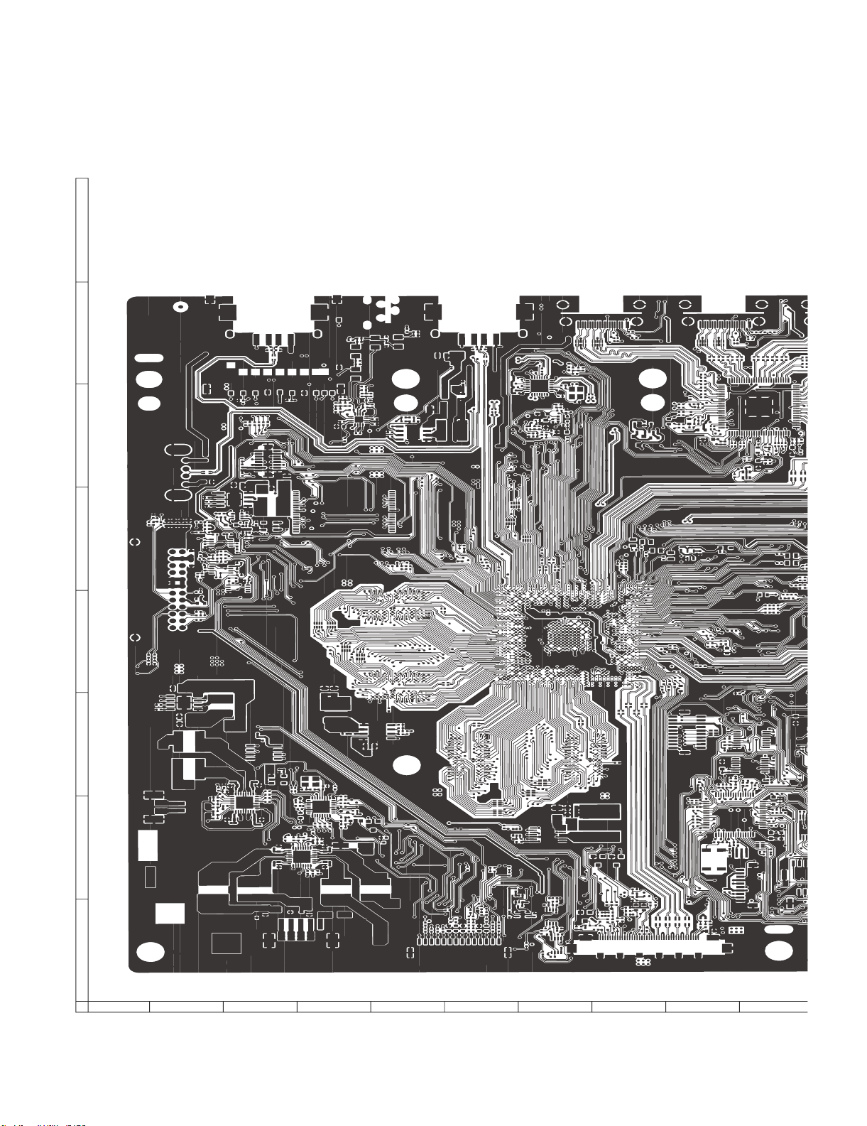
LC-60G9T / LC-70G9T
)
CHAPTER 9. PRINTED WIRING
BOARD ASSEMBLIES
[1] MAIN Unit
H
G
MAIN UNIT (A-PATTERN
F
E
D
C
B
A
1
2
3
54
6
7
8
109
9 – 1
Page 62

N )
LC-60G9T / LC-70G9T
1110
12
13
14
15
16
17
18
19
9 – 2
Page 63

LC-60G9T / LC-70G9T
H
G
F
E
MAIN UNIT ( A-SYMBOL )
D
C
B
A
1
2
3
54
6
7
8
109
9 – 3
Page 64

LC-60G9T / LC-70G9T
1110
12
13
14
15
16
17
18
19
9 – 4
Page 65

LC-60G9T / LC-70G9T
R2679
R
D2605
IC2601
R2617
0
R2041
H
G
F
E
D
C
B
A
MAIN UNIT ( CHIP SIDE-A )
FB3850
P3803
FB2002
P3802
R2102R2103
FB539
R518
FL509
VA507
R532
R647
C600
C612
D522
C611
FB548
C615
C614
R670
IC510
Q509
C613
IC507
R696
C562
R624
R665
R664
C583
C585
R632
C588
L504
C590
R618
R637
R638
R3492
R9512
R9513
FB2029
R2100
P2004
SC504
R543
R542
SC501
P2005
C625
R700
R3465
R3464
TH2001
R2043
R3440
R620
R3433
R3443
R615
R3481
R3429
C3403
C3393
C3390
R2042
R204
D2002
D2003
R2066
R2059
R2097
R2067
C2012
C2038
R2068
D2005
R2060
R2071
R2065
C2002
D515
R3432
C3386
C3389
R3430
R3431
C3385
R3428
C3387
FB3304
C3388
C3370
R3367
C3371
R3368
FB523
R613
VA501
FB525
VA502
R609
IC506
R608
D525
FB527
Q511
R699
R698
D512
C595
VA525
FB535
R507
L507
C594
R506
VA524
FB534
L506
C593
FB533
VA523
R505
L505
FB504
R551
D507
R654
FB505
R503
D508
R522
R625
D509
R533
FB506
R502
FB507
R655
D510
C521
R681
R684
R683
R685
R682
R3445
C3399
C3400
C3397
C3396
R1217
C1220
L2504
L2502
L2503
D1533
L2501
R2516
R2515
R2514
R2513
R1520
R2512
R2511
R2510
R2509
R2501
R2502
R2503
R2504
D1530
D1531
R1515
R1541
SC1513
SC1503
C2643
R2540
R2539
D2602
R2626
R2628
R2614
R2611
R2520
R2536
C2640
R2616
R2505
R2675
R2678
R2677
R2676
R2673
R2674
R2506
R2507
R2508
R1544
R1549
J514
R1224
D2016
P2001
FB2006
FB2012
FB2009
FB2007
FB2008
FB2027
FB2013
FB2014
R693 R694
FL508
FB538
R635
VA506
FB2004
R2009
FB2005
C503
C599
L502
R530
R641
C591
J9504
J9501
CN9503
CN9501
FB9503
R636
C603
VA9508
VA9507
L9513
R9515
FB9521
C9501
C9504
R9501
IC9501
C9505
FB9510
VA9501VA9503
L9503
Q512
R555
C530
Q502
C542
C543
C616
C617
R657
D518
R656
D519
IC511
Q514
L9501
R568
C539
R565
VA520
FB517
C533
Q513
R697
C609
CN9502
FB9523
FB9504
L9502
FB9517
FB518
FB508
R508
R567
C538
VA519
C532
C511
R564
C610
P2002
R2013
FB2018
FB2025
FB9509
FB9522
SC505
R504
D503
D505
FB2023
FB501
FB2022
R692
D504
R535
R695
R516
C517
R691
R627
R631
J510J511
D9402
T9401
D9401
TU1101
TU1106
TU1102
R3424
R3437
R1132
C1121
C1193
R1222
FB1110
C1106
R1143
R1227
R1232
C1175
C1174
R1102
C1180
C1179
R1103
R1130
C1211
R1237
R1233
R1141
R1109
C1181
C1182
R1105
R1129
C1177
C1176
R1185R1186R1187
C1225
C1223
C1224
C1222
C1219
C1218
C1107
L1101
C1111
D1104
SC1301
R678
R677
R679
R680
C621
R674
C623
R600
R603
R676
C622
R675
FB549
R673
FL517
FL519
FB551
FL518
FB550
C620
C618
C619
VA545
VA543
VA544
J513
C566
R612
R598
R601
R605
C569
C564
R614
FL516
FB532
FB531
R589
VA518
FB536
R595
C556
C553
C552
VA516
VA517
J509
D1534
D1535
R1536
R1537
R1533
SC1515
SC1505
R1522
Q1503
D1508
D1507
R1504
R1507
R1505
R1535
Q1507
R1521
R1508
D1532
R1516
SC1514
SC1504
C1124
R1101
D527
J9401
TU1104
C1185
C1127
C1195
C9409
R9408
R9405
C9408
R9407
R9406
C9403
C9402
TU1103
TU1105
FB1109
R1144
C1108
R1226
IC1109
C1196
C1214
R592
C561
R596
IC503
C555
R602
C624
Q505
C1212
C1139
J501
VA521
R523
FB502
R511
C501
C510
R517
1
2
3
54
6
7
8
109
9 – 5
Page 66

LC-60G9T / LC-70G9T
R3851
R3813
IC3805
C3101
D1521
FB9604
IC3301
R3374
D3101
IC3102
C3102
R9524
R9526
R9530
R3103
R3817
C3811
R3452
C3103
R3842
R3821
C3812
R3847
IC3806
IC1706
C1744
R1767
R3812
R3845
R3822
Q1703
R3850
R1766
R9602
C9605
IC9603
Q9601
C9609
R3554
R3555
R3561
R1331
R1330
R1329
R1327
R1325
R1321
R1324
R1332
R1333
R1320
C1209
R3326
C3382
C3383
FB1111
FB1112
R1235
R1234
D3103
R3349
C3104
C1210
D3102
R3102
IC9505
R9523
R9527
R9536
R9540
SC3801
FB3821
FB3820
R2041
D2605
R2617
IC2601
R2679
R1534
L2603
R2062
R2680
R1510
IC2005
IC2002
R2544
P2003
FL2001
R2099
Q2602
R2537
R2538
R2056
R2057
R2084
R3336
R2518
R1514
FB3840
IC2004
R2055
R2053
R3418
R2014
C2009
R2052
R2049
C2010
R2054
R2051
C2013
C2029
C2032
C2036
D3302
R2020
R2031
D3322
R3425
R3342
R2017
D2004
C2006
C2008
R3340
R3388
R3389
R3391
X2001
R3324
R3392
R3856
R3378
R3810
R2080
R3808
R2046
R2045
R2092
R2091
R2044
R2035
R2079
C3355
R3335
IC3304
R2039
L3804
P3301
FB3309
R3401
R3422
R3344
L3802
R3357
R3356
R3333
R3409
C3401
C3369
L3803
R3451
R3486
R3410
R3366
C3368
L3801
FB3844
C3395
FB3845
C3801
R3365
FB3851
C3802
R3447
R3866
R3865
R3863
R3864
C3803
R3446
FB3852
R3857
FB3853
R3858
C3804
C3394
C3805
C3806
R3383
C3378
R3331
C3379
R3334
R3838
Q3802
R3550
C3807
R3384
R2521
C2636
R2612
R2625
D2601
FB2606
R2517
R2607
C2628
R2608
R2605
R2606
R2604
R2601
C2622
R2602
R2535
R2534
R2533
R2532
R2531
R2530
R2529
R2528
R2527
R2526
R2525
R2523
R2524
R2522
R2519
D1528
D1529
SC1512
SC1502
L2602
Q2603
FB2605
R2647
R2652
Q2605
R2650
L2601
C2629
C2627
C2626
C2625
C2624
C2619
R1513
R1509
R1531
FB2029
R2100
P2004
P2005
C625
IC506
L507
R700
L506
L505
C3399
C3400
TH2001
R2043
R3440
R3465
R3464
L2503
R2505
R2506
R2507
R2508
R620
R3433
R3443
R3481
L2502
R615
R2539
R2611
R3429
C3403
C3393
C3390
C2640
R2616
R2042
R2040
D2002
D2003
R2066
R2059
R2097
R2067
C2012
C2038
R2068
D2005
R2060
R2071
R2065
C2002
D515
R3432
C3386
C3389
R3430
R3431
C3385
R3428
C3387
FB3304
C3388
R3367
C3370
C3371
R3368
L2504
C2643
R2540
D2602
R2626
R2628
R2614
R2520
R2536
R2675
R2678
R2673
R2677
R2676
R2674
R1544
R1549
23
R613
01
25
02
R609
R608
D525
27
Q511
D512
C595
VA525
FB535
R507
C594
R506
VA524
FB534
C593
FB533
VA523
R505
B504
R551
D507
R654
B505
R503
D508
R522
R625
D509
R533
B506
R502
B507
R655
D510
C521
R684
R685
682
R3445
C3397
C3396
L2501
R2516
R2515
R2514
R2513
R2512
R2511
R2510
R2509
R2501
R2502
R2503
R2504
D1530
D1531
C3808
FB3826
FB3825
R3837
R3836
R3805
R3846
FB3827
SC1501
SC1511
FB3831
R3835
R3834
R3844
R3848
Q3803
D1523
FB3832
L9602
R3828
R3827
R3829
Q3801
C9615
C9614
IC3504
R3562
C9517
X9501
R9537
C9519
R1547
R1503
R1545
R1546
D1524
R1764
R1763
R3496
R3330
R9609
FB1713
R1709
R3495
R3327
R3538
R3542
R3467
R9517
FB1712
R1708
R3471
R3470
R3469
VA9504
FB1711
R1707
R3494
R3483
R3381
L9504
VA9502
J9502
FB1709
FB1710
R1706
R3484
IC3503
R3546
R3466
R3488
R3468
P1701
FB1708
R1705
R3485
R3493
R3472
FB9601
C9638
FB1707
FB1705
R1704
L9605
R1711
FB1706
R1712
R3516
R3501
C9641
FB1703
C9630
FB9602
FB1702
FB1704
FB1701
R1703
VA527
R9628
R9630
R9633
C560
R3402
IC9607
C9636
R9619
R9631
FB521
P1903
D1908
C1924
C1919
D1905
L1907
VA3104
R1950
C1957
C9640
R1958
L1903
C1918
C1930
C1927
C1916
R1902
R1946
R1959
IC1902
R1947
R1961
R1967
R1965
R1945
R1955
R1953
C1935
C1929
C1915
IC1903
R1933
R1937
R1934
R1935
IC3104
C3112
L9601
FB3808
FB3807
C3815
FB3806
C3813
FB3809
IC3810
R3871
R3872
C9631
R9636
R3147
VA3102
C3817
C9623
R3119
R3124
R3120
R3853
C3809
R3803
R3814
D9608
Q9603
C3810
IC9606
C3814
IC3801
R3816
R3852
R3807
R3815
FB3811
R3802
R3820
R3806
R3859
R3809
R3819
R3811
IC3802
R3849
FB3815
C3818
R3855
R3843
FB3814
C3819
R9632
R9626
C9619
C9618
R9618
FB9518
L9510
FB9519
C3824
R9627
IC9605
C9622
Q9602
C9629
L9604
FB9603
C9626
SC3101
R3154
R3146
R3145
R3142
R3144
FB3810
C3816
L1906
L1902
C9612
C9613
FB3857
FB3856
FB3835
IC9601
C9606
FB3834
FB3818
C9603
C9607
FB3817
P3801
FB3812
J9505
P1904
C3820
FB3819
R3854
C3822
C3821
FB3813
FB3816
L9507
SC3102
VA9505VA9506
J9503
L1904
L1908
R1942
R1943
R1944
C1917
IC1901
C1934
R1971
R1956
R1951
C1902
Q1702
D1702
D1707
R1913
R1912
C9620
IC9604
R9617
R9616
C9616
C9617
R9623
R3529
IC3502
R3522
R3518
R3521
R1969
C1936
R1954
R1963
R1929
R1928
R1927
R1926
R1777
R1778
R1917
R1916
R1907
R1903
R1901
C1715
C9624
R1771
FB1917
IC1703
R1930
C1718
R1751
R1738
C1703
R1741
R1737
C1702
X1701
L9603
C9625
C9621
R3504
R3508
IC3501
R3408
R3395R3396
IC3103
C9627
C9632
R593
R1756
C1727
C1732
C1726
R1713
IC1702
R1714
C1717
R1753
R1752
C1714
C1710
R1755
R1750
C1721
C1720
R1702
C1706
R1754
C1719
C1709
R1749
C1716
C1705
R1701
R607
R591
C558
R590
R594
R606
C559
C554
FB522
VA526
J504
1110
12
13
14
15
16
17
18
19
9 – 6
Page 67

LC-60G9T / LC-70G9T
H
G
F
E
D
MAIN UNIT ( B-PATTERN )
C
B
A
1
2
3
54
6
7
8
109
9 – 7
Page 68
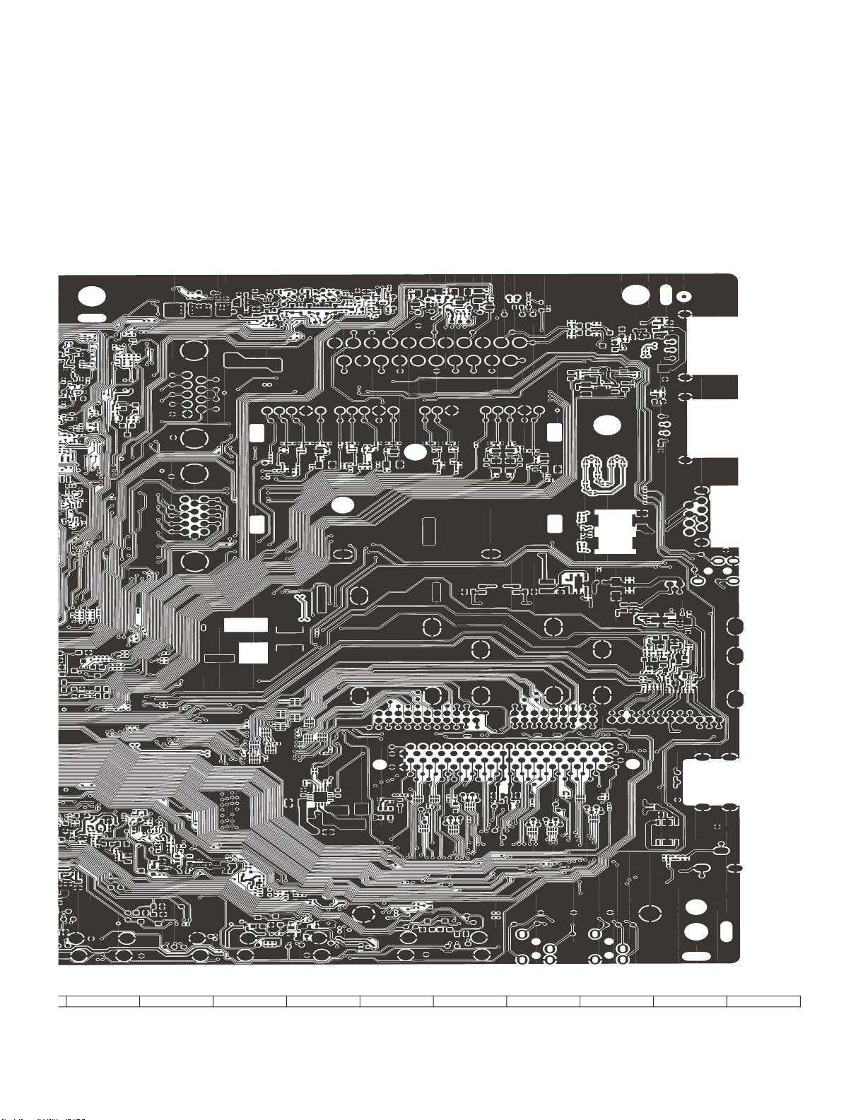
LC-60G9T / LC-70G9T
1110
12
13
14
15
16
17
18
19
9 – 8
Page 69

LC-60G9T / LC-70G9T
H
MAIN UNIT ( B-SYMBOL )
G
F
E
D
C
B
A
1
2
3
54
6
7
8
109
9 – 9
Page 70

LC-60G9T / LC-70G9T
1110
12
13
14
15
16
17
18
19
9 – 10
Page 71

LC-60G9T / LC-70G9T
5
7
2
C2024
H
MAIN UNIT ( CHIP SIDE B )
R1978
C1921
R1931
C1730
Q1701
Q506
FB1901
Q510
R671
C1945
C1904
C1912
R3505
R628
FB1906
C1946
FB1905
R1974
FL3505
C3538
Q501
C604
R623
D1903
R1769
C1725
C1723
Q504
R1770
R3503
R3506
C1722
C3505
R1768
C3507
FL3502
C1942
D1901
C1928
C1959
Q1705
C1926
C1938
C3516
R3531
C3518
C3512
R3523
R3525
R3507
R3519
R3509
C3508
C3509
R3514
R3515
FL3503
C3501
R3510
C1724
R1710
R3380
R3455
R3376
R3377
R3490
R3426
R3491
R3489
R3823
R1909
R3824
R1911
R1910
C3539
FL3508
C3524
C3525
C3526
R3536
R3537
C3527
FL3509
R3535
R3532
C3519
R3534
R3533
C3520
FL3507
C3521
C3522
C3523
R3530
C3517
FL3506
R3528
R3512
R3513
C3502
R3511
C3511
R3527
R3121
C3110
R3122
C3514
FL3504
R3517
R3502
C3510
FL3501
C3503
R3526
D9611
C3513
C3515
C3504
C3506
R572
R611
R573
C9633
R9629
R575
D3333
D9612
C9634
C9635
C9637
FB9513
R3461
R3405
R3403
C3302
R3393
C3398
R3407
IC3302
C3404
R3400
R3456
C3301
R9504
R3394
R9502
IC9502
C9503
R9511
R9514
C9502
FB1908
C1954
FB1907
FB1903
FB1904
R3139
C1950
C1949
C1958
C1937
C1933
R1976
FB1902
R1989
R1940
R1938
R1939
C1911
R1936
R1941
R1964
R1988
R1970
C1731
D1705
C1742
R1765
C1711
D9610
D9609
R3520
R3524
C1953
G
F
E
FB3854
FB3855
C1948
C1956
R1968
R1975
FB1913
FB1914
C1940
C1952
C1923
D1902
FB1915
C1932
C1961
FB1916
C9604
R9608
FB3804
FB3805
FB3801
C1903
FB3802
R1981
C1920
C1944
D1906
R9615
R9611
R9613
R1977
C1941
C1906
C1907
C1905
C1910
C3121
C3124
R3130
R3131
R3129
R3128
D9615
D9602
D9606
D9607
D
R3111
R3109
C
Q9604
B
R9621
R9620
VA3101
R2073
D2006
Q2009
C3111
IC3105
R3127
FB9516
R2072
R3138
R3153
R3136
VA3103
C9628
R9624
IC9602
R3101
R3137
C9509
C9608
C3122
R3107
R3112
D9613
C3106
R3132
R3105
R3160
R3108
R3104
D9614
R9622
D1706
D1703
R672
R3155
R3143
VA3106
VA3105
R3159
VA3107
R3148
FB3102
R9508
R9507
FB9515
C9508
IC9503
VA3108
C9507
R3152
R3156
R604
R588
A
C3319
C3325
R3423
R3473
FB9511
C3318
C9506
R3870
R3869
C3823
R3841
C1757
R1781
Q1704
D1704
C1759
C1755
R1775
R1785
R1784
R9606
R9607
C9602
C9601
D9601
R9605
R9601
R9604
C9639
R9603
R3553
R3557
R3539
R3545
R3559
R3540
R3543
R3541
R3544
C3320
C3326
C3330
R3307
C3314
C3315
R3302
R3301
C3332
R3310
C3343
R3309
C3331
C3322
C3324
R3313
FB3302
C3333
C3334
C3339
R1328
R3116
R3113
C9516
R9525
C9515
C9513
R9528
R9529
R9531
R9532
R9535
R9534
C9521
C9524
R9542
C9522
R9541
R9539
R9538
R1548
R1538
R3560
C3304
C3337
R1322
R3110
C9514
C9518
C9520
C9523
D1506
IC3809
R3558
R3547
C3528
C3323
R3308
R1326
C9611
R9614
C9610
R9612
C3329
C3328
C3317
C3338
R1323
FB9524
R3556
C3529
C3340
R1104
D1505
D3104
R3548
C3531
R3305
R3306
C3309
C3307
R9518
R1540
R1519
C3316
D9603
C3532
C3534
FL3510
C3327
C3321
C3310
R3118
FB1502
R3480
C3402
C1109
FB3833
D9604
C3530
C3342
R3477
R3478
R3438
R3439
R3826
R3303
C3305
R3479
R3482
R9533
R3804
R3825
FB3830
FB3829
R3830R3831
D9605
R3549
C3303
R3338
R3476
R3474
R3833
R3832
C1501
D1510
FB3828
R3355
R3311
R3415
C3312
R3475
D1513
FL3512
FB3308
C3336
C3345
C3313
R3397
C3533
C3536
C3306
C3347
R3458
R3404
R3414
R3457
FB3307
R3552
C3535
C3346
D1517
R3801
C3540
FL3511
R3551
C3335
R3416
C3354
C3376
C3344
C3348
FB3824
R3337
R3379
C3351
FB3823
R3839
C3308
C3341
R3387
R3413
FB3303
C3349
R1502
FB3841
FB3822
C3311
R3412
R3448
R3316
R3386
R3314
L1502
R3399
C3377
R3315
R3385
IC3303
R2632
R2648
R1501
D3301
R3321
R3382
R3358
R3390
Q3301
D3303
R2645
FB3847
FB3846
R3840
R3323
R3398
R3498
FB3310
FB3311
R3499
C3352
Q2601
FB3842
FB3843
FB3803
R3312
R3304
C3353
R3375
C3381
C3380
R3348
R3868
R3867
R3421
R3322
R3347
X3301
FB3301
R2633
R3861
R3862
R3860
R3325
R3487
C3350
R3345
R3454
C3356
R2105
R2104
R3339
R3343
C2014
R2090
R2063
C2016
R2101
R2064
C2037
R2093
R2094
R2086
C2025
R2085
R2098
R2088
R2087
R661
R658
Q507
C578
C577
R659
R660
Q508
R2036
C2021
C2022
C2019
C2020
R2003
R2023
R2024
Q2006
R2025
IC2009
C2004
IC2003
R2002
C2005
Q2001
R2034
C2003
R2033
D2001
Q2005
R2037
Q2007
Q2010
R2047
R2032
R2061
R2058
R2050
C2011
R2038
IC2008
R2077
R2078
R2074
Q2008
R2075
R2076
R2070
C2007
C2034
R2083
C2033
R2069
R2048
C2015
IC2007
IC2006
C2035
R2007
C2030
R2030
R2011
IC2001
C2001
C2028
C2031
R3411
R3460
R3406
R3332
R2619
D2501
C2611
C2501
D2604
C2654
C2638
C2610
D3319
R2541
C2651
C2601
C2602
C2606
R2639
R3497
D2603
R2618
D3318
D3308
R2629
R3351
C3359
D2606
C2641
C2603
R3359
D3309
R3360
C2637
R3350
C3358
R2542
R3353
C3357
C3372
D3321
R2613
C3375
C3362
C3363
R2603
R3352
C3360
R3372
C2633
C2635
C2634
R2640
FB2601
R2663
R3354
C3361
R3371
C3373
C3374
FB2604
C2623
C2653
R689
R690
R3369
R3370
R3341
C1510
R152
IC1508
R2694
Q1508
R157
C2621
C2618
C2617
C2616
D151
R3419
R3449
R3328
R3436
R3417
R3317
R3346
R3420
R3450
R3442
R3435
R3441
C3392
C2630
R2695
R2696
R2697
C3384
C3366
R3363
D1518
R3434
C3391
R3364
C2631
C2655
R2664
C2615
R2630
C2612
C2652
C2650
C2608
C2607
D3320
R3373
C3364
R3361
C3367
C3365
R3362
C2642
R2615
R2620
C2639
C2632
R2689
R2638
C2614
C2613
C2605
C2604
C2609
C2644
IC2602
C2648
D1514
C1502
R3329
R3459
R3318
R3427
D3329
1
2
3
54
6
7
8
109
9 – 11
Page 72

LC-60G9T / LC-70G9T
1
Q2008
C2610
R2011
R2069
R2096
D9405
FB3838
FB2024
FB2020
FB2026
FB2001
R2001
R2015
FB2003
C2039
C2017
C2027
D2011
R2004
R2082
C2018
R2005
R2089
C524
R562
R610
R538
C509
R515
R528
R513
R1189
C1221
R1188
R1216
C1217
R1215
C1216
C1215
R1532
R1539
R1551
R1562
D1527
C1517
R1583
R1555
IC1510
R1511
R1563
D1520
D1516
D1525
D1526
R1543
C1506
R1512
VA1501
FB3848
FB3849
FB3837
FB3836
R3350
C3358
D3309
R2542
C3372
R2090
R3353
C3357
D3321
R2613
C3375
R2063
R3352
C3360
R3372
C3362
C3363
C2633
R2640
FB2601
R2603
C2016
R3354
C3361
R3371
C2635
C2634
FB2604
R2663
R2101
R2064
C2037
R2093
R2094
R2086
C2025
R2085
C2024
R2098
R2088
R2087
R661
R658
Q507
C578
C577
R659
R660
Q508
R689
R686
R690
R687
C3373
R3369
C3374
R3370
R3341
C2621
C2623
C2653
C2618
C2617
R688
FB1108
R1150
R1149
FB1107
R3320
C1510
R1527
IC1508
R2694
R2692
R1569
R1552
R1553
Q1508
R1571
IC1509
C1516
R1572
R1525
R1554
R1570
R1573
Q1504
R1574
Q1505
C2616
IC1507
R1528
C1509
C1508
D1511
Q1509
R1530
C1503
D1515
D1519
R1506
R2024
Q2006
R2025
IC2009
C2004
IC2003
R2002
C2005
R2034
C2003
033
D2001
R2037
Q2010
R2061
IC2008
R2077
R2078
R2075
R2076
C2034
C2033
IC2006
C2014
2035
R2007
C2030
R2030
IC2001
C2028
C2031
R3351
R3497
C3359
D3318
D3319
R3359
D3308
R3360
D2603
R2541
D2606
R2629
R2618
C2641
D2604
C2654
C2638
01
C2637
R2639
C2651
C2601
C2602
C2606
C2603
R1526
C1507
R1550
R1558
FB3839
R1140
R1190
R1542
VA529
FB514
C1113
D1504
R559
C505
R525
Q1506
FB2028
R2095
E1101
R1556
C1504
D2012
C527
R1139
R1145
R1191
R1192
R1529
R1523
FB2021
FB2019
FB2010
FB2011
D2007
D2013
D2008
D2009
VA528
VA514
C529
R558
FB513
FL504
FB519
C544
R579
R536
R617
R1218
R1138
R1136
R1137
R1207
R1106
R1142
R1111
R1125
C1116
IC1105
C1114
C1104
R1524
R1567
FB1503
Q2002
R2018
D2014
VA531
R527
C507
C1101
R563
R2021
D1101
R2022
R534
D2015
R2019
R2010
C520
R557
R510
FB509
FB510
D2010
R2026
R556
R531
R509
D1102
Q1501
C504
C2026
R2006
R2008
C526
R521
R1334
R1517
R2016
Q2003
R2081
R2027
Q2004
R2012
VA530
R2029
R2028
R586
C545
R1319
VA515
FB520
R580
IC1301
VA509
R541
R537
C597
C596
VA508
FB9508
FL511
FB540
FB9507
FB9514
C534
VA533
C525
VA532
R561
FB516
FL505
R529
R540
C512
R520
R1315
C1305
R1309
R1310
FB1301
R1312
R1306
R1305
R1518
R1557
Q1502
D1501
D1512
D1522
C528
R1317
FB9506
C1505
FB541
FB515
C506
R539
R526
C1307
D1301
FB9505
R560
R519
R634
C598
R544
VA510
FL512
R9411
FB537
VA512
R570
R577
C1112
L1104
C1303
R1304
R1318
FB529
C1302
FL513
C540
FB1302
FL514
R584
R9410
FB9501
FB9502
D9403
R9409
C607
R553
FB511
C531
R571
FB512
R552
R569
R554
C608
C522 C523
R1759
R1760
C1738
C1736
C1734
R1757
C1740
C1741
C541
VA513
VA511
C537
FL515
FB530
FB528
FL510
R9543
R9544
R578
R585
R583
R633
R576
C550
C548C549
R587
R9546
R9521
R9519
R9520
R9404
R9403
C9410
C9407
C9406
C9404
C9405
C9401
R9402
R9401
R1131
FB1104
IC1110
R1220
C1118
C1306
C1205
C1213
R1221
C1304
R1311
R1314
R1313
R1316
R1301
R1302R1303
L1105
C1308
R1308
R9522
R1307
Q516
IC1705
R1758
R9545
Q515
R630
R629
C1735
D1105
L1103
C9512
R1761
R1762
C1733
C1189
R1195
C1739
C1737
C1184
C1188
C1130
R1219
FB1105
R1201
FB1106
R1202
C1123
R9510
C9511
R9509
C9510
IC9504
FB9520
R9516
R9505
R9506
R9503
FB9512
VA542
VA535
VA536
C9411
C1178
C1202
R1121
Q1106
R1208
C1204
R1231
R1151
R1117
R1135
R1119
R1162
R1164
R1124
C1140
C1203
R1230
Q1103
IC1104
C1161
C1173
Q1107
C1141
R1177
R1114
R1123
C1153
R1176
R1118
Q1102
C1145
R1112
R1113
R1179
R1229
L1107
C1208
C1105
C1138
C1129
R1223
R1178
C1206
R1228
FB1103
C1110
R1225
C1133
C1207
C1128
IC1102
R514
C508
R512
C502
FB503
VA522
R524
1110
12
13
14
15
16
17
18
19
9 – 12
Page 73

LC-60G9T / LC-70G9T
H
TCON UNIT ( A-PATTERN )
G
F
E
D
C
B
A
1
2
3
54
6
7
8
109
9 – 13
Page 74

LC-60G9T / LC-70G9T
1110
12
13
14
15
16
17
18
19
9 – 14
Page 75

LC-60G9T / LC-70G9T
H
TCON UNIT ( A-SYMBOL )
G
F
E
D
C
B
A
1
2
3
54
6
7
8
109
9 – 15
Page 76
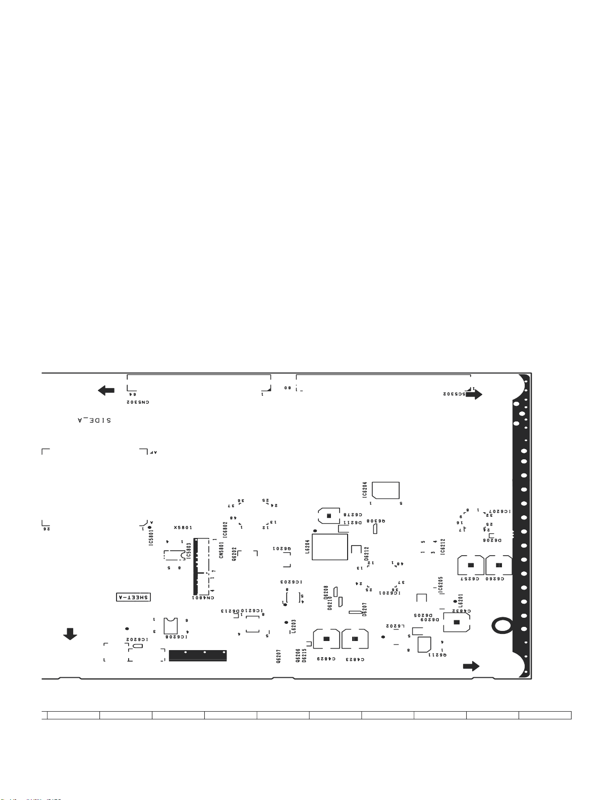
LC-60G9T / LC-70G9T
1110
12
13
14
15
16
17
18
19
9 – 16
Page 77

LC-60G9T / LC-70G9T
H
TCON UNIT ( CHIP SIDE A )
G
F
E
D
C
B
A
1
2
3
54
6
7
8
109
9 – 17
Page 78

LC-60G9T / LC-70G9T
1110
12
13
14
15
16
17
18
19
9 – 18
Page 79

LC-60G9T / LC-70G9T
H
TCON UNIT ( B PATTERN )
G
F
E
D
C
B
A
1
2
3
54
6
7
8
109
9 – 19
Page 80
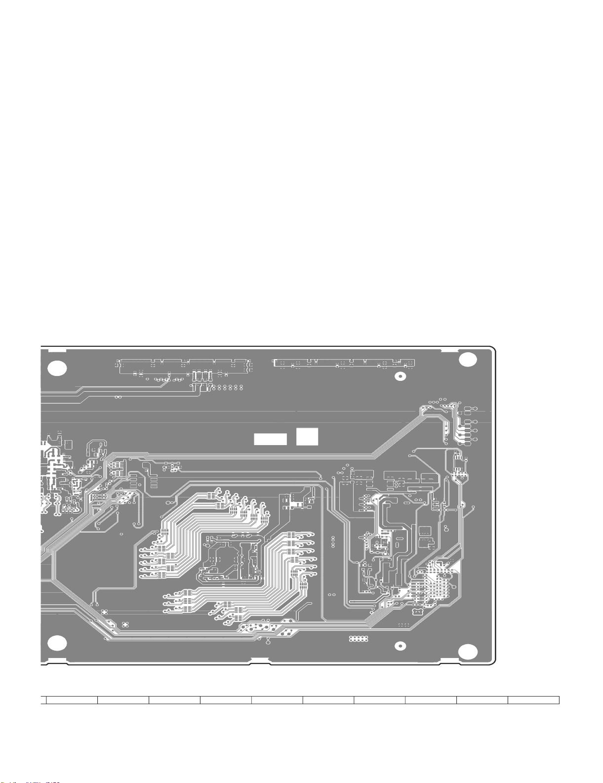
LC-60G9T / LC-70G9T
1110
12
13
14
15
16
17
18
19
9 – 20
Page 81

LC-60G9T / LC-70G9T
H
T-CON UNIT ( B-SYMBOL )
G
F
E
D
C
B
A
1
2
3
54
6
7
8
109
9 – 21
Page 82

LC-60G9T / LC-70G9T
1110
12
13
14
15
16
17
18
19
9 – 22
Page 83

LC-60G9T / LC-70G9T
CHAPTER 10. SCHEMATIC DIA-
GRAM
[1] DESCRIPTION OF SCHEMATIC DIAGRAM
1. VOLTAGEMEASUREMENT CONDITION:
1) The voltages at test points are measured on exclusive AC adaptor and the stable supply voltage of AC 110-240V.Signals are fedbyacolour bar signal
generator for servicing pur
2. INDICATION OF RESISTOR & CAPACITOR:
RESISTOR
1)The unit of resistance ""is omitted.
(K=k =1000 , M=M ).
2) All resistors are ± 5%, unless otherwise noted.
(K= ± 10%, F= ± 1%, D= ± 0.5%)
3) All resistors are 1/16W, unless otherwise noted.
CAPACITOR
1) All capacitors are F, unless otherwise noted.
(P=pF=
2) All capacitors are 50V, unless otherwise noted.
F)
.
pose and the above voltages are measured with a 20k ohm/V tester.
CAUTION:
T
his circuit diagram is original one,
difference from yours.
SAFETY NOTES:
1) DISCONNECT THE AC PLUG FROM THE AC OUTLET
BEFORE REPLACING PARTS.
2) SEMICONDUC
POTENTIAL SHOCK HAZARDS WHEN THE CHASSIS IS
OPERATING.
IMPORTANT SAFETY NOTICE:
ARTS MARKED WITH " "
P
FOR MAINTAINING
REPLACE THESE PARTS WITH SPECIFIED ONES FOR MAINTAI N I NG THE SAFETYAND PERFORMANCE OFTHE SET.
TOR HEAT
THE SAFETY OF THE SET.BESURETO
therefore there may be
SINKS SHOU
( )
LD BE REGARDED AS
aslight
ARE IMPORTANT
10 – 1
Page 84

LC-60G9T / LC-70G9T
Near Tuner
TO MAIN4(CPU)
TO MAIN4(CPU)
Near SOC
004
TUN_GAIN_SW
TUN_GAIN_SW
TO MAIN4(CPU)
SCL2_TUNER
N_TUN_RST
CPU_IF_AGC
TUN_IFP
N_TUN_T2_RST
N_TUN_SAT_RST
TUN_IFN
004
004
0
0
*R1150
*R1149
D_IF-
D_IF+
SDA2_TUNER
004
004
004
004
004
004
004
TP1110
*FB1111
0241TA
*FB1112
0241TA
10K
*R1104
10V
*C1109
0.047u
SCL2__TUNER
IF__AGC
SDA2__TUNER
SDA0_400k
N_TUN_RST
N_TUN_SAT_RST
N_TUN_T2_RST
TO MAIN7(UCOM)
SDA0_400k
TUNER_CVBS
SIF
TUNER_CVBS_BYPASS
SCL0_400k
TO MAIN2(TARMINAL)
002
004
004
004
TP1112
SCL0_400k
VP
10uH
*L1107
IF+3.3V
16V
10u
KZA510WJPZ
*C1129
TO MAIN10(POWER)
3479A18P
*IC1109
D+3.3V
M+2.3V
010
010
D+3.3V
DUNTKG216WE**
10V
KZA761WJQZ
*C1196
4.7u
4
3
Vin
N.C
2
GND
1
5
ON
Vout
10V
4.7u
*C1195
KZA761WJQZ
16V
10u
*C1127
KZA510WJPZ
MAIN1(TUNER)
(MASTER)
SPICA2
Near Tuner
N_TUN_RST
SDA2__TUNERTU_SDATA
SCL2__TUNER
*FB1110
0241TA
*FB1109
0241TA
1K
*R1101
*C1106
10P
*C1108
0.1u
*C1124
TU_SCLK
N_TU_RESET
10 11 12
T-HNIM
TAIWAN
123456789
*TU1103
AA084WJQZ
D_IF-D__IF-
D_IF+
IF__AGC
10K
*FB1106
0241TA
*FB1105
0241TA
*R1151
0.047u
10P
IF___AGC
D__IF+
D__IF-
CVBS
TU__SIF
IF+3.3V
IF+1.8V
TU_SCLK
TU_SDATA
N_TU_RESET
TU_GAIN_SW
AT+5V
*C1123
Near Tuner
IF___AGC
D__IF+
*C1110
0.01u
25V
25V
*C1185
0.01u
10V
0.1u
*C1133
Near Tuner
10 – 2
Page 85

LC-60G9T / LC-70G9T
D+5V
D+3.3V
TO MAIN10(POWER)
010
010
TO MAIN4(CPU)
VGA_SCL
VGA_5VPWR
BU+3.3V
TO MAIN7(UCOM)
IR_RS
UART_232CTOCPU
UART_CPUTO232C
010
0
R658
007
007
007
M3221EIP
IC506
3.303.30003.33.3
9
8
UART_232CTOCPU
R1_out
R1_in
7
NC
10
V-
7
8
6
11
C2-
5
T1_in
UART_CPUTO232C
12
FORCEON
13
T1_out
14
GND
10K
R620
15
Vcc
16
SHDN
10V
0.1u
C578
C577
4.7u
10V
KZA761WJQZ
100
R613
1/10W
100
R609
100
1/10W
R608
D525
FB527
0241TA
FB525
0241TA
VA501
FB523
0241TA
RTS
9
CTS
DSR
6
7
8
11
45
2
3
TxD
RxD
6
5
3
4
C625
0.1u
C2+
4
C1-
3
V+
2
C1+
0 3.3 3.3 3.3 3.3 0 0 0
1
EN
1/10W
EXA697WJQZ
5.6V
VA502
VXA236WJ
VXA236WJ
10
1
DCD
16V
1
2
D512
Vertical type
D-SUB
RS232C
NB122WJQZ
*SC504
VGA_SDA
SC/Y_CVBS2_IN
RED1/C1
GREEN1
SC_RGB_COM
TO MAIN3(HDMI)
003
003
003
CZ
CZ
R503
R502
0
0
10V
*C521
0.1u
D515
5.6V
EXA697WJQZ
4.7K
R655
4.7K
R654
3
BAV70
1
2
220
R522
5.6V
D508
EXA697WJQZ
D507
5.6V
EXA697WJQZ
0241TA
FB505
FB504
0241TA
11
121314
678
9
16
*SC501
PC_IN
NB123WJQZ
123
Vertical Type
75
1/4W
R506
75
R505
1/4W
VA524
VA523
VXA238WJQZ
VXA238WJQZ
BLUE1
004
004
004
004
004
PC_VSYNC
PC_HSYNC
220
R533
D510
EXA697WJQZ
5.6V
*FB535
A527WJ
D509
5.6V
EXA697WJQZ
FB506
0241TA
FB507
0241TA
*FB534
A527WJ
15
10
17
5
4
1/4W
75
R507
VA525
VXA238WJQZ
CVBS_COM
COMP1_Y
004
PC_BLUE
PC_GREEN
CVBS_SIDE_IN
CVBS1_IN
COMP1_COM
004
TO MAIN4(CPU)
PC_HSYNC
004
PC_RGB_COM
R615
0
COMP1_PLUG
004
004
004
004
PC_VSYNC
PC_RED
PC_GREEN
PC_BLUE
PC_RGB_COM
004
004
004
004
004
PC_HDMI_L
1K
R523
R524
1K
100K
R517
R512
1K
1K
R511
FB503
0104TA
0104TA
FB502
1
EA111WJQZ
J501
PC AUDIO_IN
COMP1_Pb
COMP1_Pr
004
004
PC_RED
*FB533
A527WJ
TO MAIN4(CPU)
TO MAIN1(TUNER)
SLOWSW1
SC1FSW
TUNER_CVBS_BYPASS
CVBS1_PLUG
CVBS2_PLUG
004
004
PC_HDMI_L
004
004
PC_HDMI_R
C510
1000P
R514
100K
2L3
R
INOUT_SW
MONI_HP_R
CVBS_TU_OUT
HP_PLUG
MONI_HP_L
004
PC_HDMI_R
CH
C508
C502
TO MAIN9(AUDIO AMP)
004
001
009
004
004
004
009
TQ
33
1/4W
R606
HP_PLUG
UN-PLUGGED:H
PLUGGED:L
CH
1000P
R604
100K
FB521
0104TA
R588
1K
220P
VA522
VXA236WJ
220P
C501
VA521
VXA236WJ
12R3L4
J504
EA115WJQZ
HP Jack/AUDIO OUT
0104TA
FB522
AUDIO_MUTE
TO MAIN9(AUDIO AMP)
009
*R628
0
3
*Q506
IMH23T110
405
TO MAIN4(CPU)
TUNER_L_OUT
SC1_IN_R
TUNER_R_OUT
COMP1_SOY
SC1_IN_L
HPOUT_MUTE
004
004
009
009
004
004
009
4.7K
ISA1530AC
Q510
R672
3.3
2.5
R671
1K
3.2
TQ
33
1/4W
R607
0
2.66
102
6
0
2.66
0
*R623
C560
R593
100
R590
100
C554
1000P
VA527
1000P
C559
100K
TQ
R594
1/4W
C558
TQ
1/4W
R591
100K
VA526
CVBS1_IN_R
VXA236WJ
0.01u
0.01u
VXA236WJ
COMP1_IN_R
CVBS1_IN_L
CVBS2_IN_R
CVBS_SIDE_IN_L
CVBS_SIDE_IN_R
CVBS2_IN_L
004
COMP1_IN_L
004
004
004
004
004
004
H:NORMAL
L:PDN
D527
CDL37114
0
IC503
45
3.6
7
2.4
456
3
2
1
004
AUDIO_MUTE
LTC014EEB
Q505
MUTE
5
47K
R602
123
& SPDIF MUTE
SPDIF BUFFER
AHT1G08W
5
R592
100
OPT_OUT
C555
0.1u
10V
MAIN2(TERMINAL)
DUNTKG216WE**
(MASTER)
SPICA2
CVBS2_PLUG
SC/Y_CVBS2_IN
*R617
0
CZ
*C544
*R579
*R572
4.7K
*FB519
100
0244TA
*R562
*VA514
CVBS1_IN
CVBS1_PLUG
470P
50V
75
1/4W
R573
4.7K
100
*R563
VXA236WJ
COMP1_PLUG
0
R586
CZ
470P
C545
50V
75
1/4W
R580
R575
4.7K
FB520
0244TA
*R570
*VA515
VXA236WJ
COMP1_Pb
COMP1_SOY
COMP1_COM
0
0
0
*R686
*R687
*R688
CZ
CZ
CZ
0
*R587
CZ
10P
*C548
56
0
18
*R583
*R633
*R576
CZ
*FB528
100
0244TA
*VA511
VXA238WJQZ
COMP1_Pr
0
0
*R689
*R690
CZ
CZ
10P
10P
*C549
50V
18
1/4W
*R577
*FB529
0244TA
VXA238WJQZ
*VA512
*C550
50V
50V
56
56
18
1/4W
1/4W
*R584
*R585
*R578
*FB530
0244TA
*VA513
VXA238WJQZ
COMP1_Y
CVBS_COM
A137 / A125
ZA125WJN1
*J510
1
246789101112
5
3
for ASIA
*VA528
VXA236WJ
*C527
1000P
*FB513
*FB514
0104TA
0104TA
*R538
1K
*R536
1K
1000P
*C509
1000P
100K
*C505
*R528
100K
*R525
*R513
1K
*R515
1K
CVBS2_IN_R
CVBS2_IN_L
*VA530
VXA236WJ
C526
1000P
VXA236WJ
*VA529
*C524
1000P
C520
FB509
FB510
0104TA
0104TA
R534
1K
R531
1K
1000P
C507
1000P
100K
C504
R527
100K
R521
R509
1K
R510
1K
CVBS1_IN_L
CVBS1_IN_R
14151617
18
13
*VA532
VXA236WJ
*C528
1000P
*VA533
*VA531
VXA236WJ
*FB515
1000P
0104TA
*R539
*R519
VXA236WJ
*C525
1000P
*FB516
0104TA
*R540
1K
1K
1000P
*C512
1000P
100K
*C506
*R529
100K
*R526
1K
*R520
1K
COMP1_IN_L
COMP1_IN_R
10 – 3
Page 86

LC-60G9T / LC-70G9T
D+3.3V
TO MAIN10(POWER)
010
010
TO MAIN4(CPU)
VGA_SCL
VGA_SDA
TO MAIN7(UCOM)
BU+3.3V
D+5V
010
0
R658
IR_RS
UART_CPUTO232C
UART_232CTOCPU
007
007
007
M3221EIP
IC506
3.303.30003.33.3
9
8
UART_232CTOCPU
R1_out
R1_in
7
NC
10
V-
7
8
6
11
C2-
5
5
C2+
4
C1-
3
V+
2
C1+
03.33.33.33.3000
1
EN
1/10W
EXA697WJQZ
5.6V
VA502
VXA236WJ
VXA236WJ
10
1
DCD
6
3
4
0.1u
C625
16V
1
2
Vertical type
D-SUB
RS232C
NB122WJQZ
*SC504
T1_in
UART_CPUTO232C
12
FORCEON
13
T1_out
14
GND
10K
R620
15
Vcc
16
SHDN
10V
0.1u
C578
C577
4.7u
10V
KZA761WJQZ
100
R613
1/10W
100
R609
100
1/10W
R608
D525
FB527
0241TA
FB525
0241TA
VA501
FB523
0241TA
RTS
9
CTS
DSR
6
7
8
11
45
2
RxD3TxD
VGA_5VPWR
TO MAIN3(HDMI)
003
003
003
CZ
CZ
R503
R502
0
0
10V
*C521
0.1u
D515
5.6V
EXA697WJQZ
4.7K
R655
4.7K
R654
3
D512
BAV70
1
2
R533
220
R522
D510
EXA697WJQZ
5.6V
5.6V
D508
EXA697WJQZ
D509
D507
5.6V
EXA697WJQZ
FB506
0241TA
0241TA
FB507
FB505
FB504
0241TA
16
*SC501
PC_IN
NB123WJQZ
Vertical Type
75
R505
VA523
VXA238WJQZ
1112131415
789
6
12345
R506
1/4W
VA524
VXA238WJQZ
0241TA
10
17
75
1/4W
VA525
VXA238WJQZ
COMP1_Y
SC/Y_CVBS2_IN
BLUE1
GREEN1
SC_RGB_COM
RED1/C1
004
004
004
004
004
PC_BLUE
PC_VSYNC
PC_HSYNC
220
*FB535
A527WJ
5.6V
EXA697WJQZ
*FB534
A527WJ
1/4W
75
R507
CVBS_COM
COMP1_Pr
CVBS1_IN
COMP1_COM
COMP1_Pb
004
004
004
PC_RED
PC_GREEN
*FB533
A527WJ
004
TO MAIN4(CPU)
PC_HSYNC
004
PC_RGB_COM
R615
0
COMP1_PLUG
CVBS_SIDE_IN
004
004
004
004
PC_RGB_COM
PC_BLUE
PC_VSYNC
PC_RED
PC_GREEN
004
004
004
004
004
PC_HDMI_L
PC_HDMI_R
1K
R524
R523
1K
100K
R517
R512
1K
1K
R511
0104TA
FB503
0104TA
FB502
1
R
EA111WJQZ
J501
PC AUDIO_IN
TO MAIN4(CPU)
TO MAIN1(TUNER)
MONI_HP_R
CVBS_TU_OUT
TUNER_CVBS_BYPASS
004
HP_PLUG
UN-PLUGGED:H
R604
100K
J504
EA115WJQZ
HP_PLUG
INOUT_SW
004
004
PLUGGED:L
R588
1K
12R3L4
MONI_HP_L
TO MAIN9(AUDIO AMP)
009
009
TQ
33
1/4W
R606
FB521
0104TA
HP Jack/AUDIO OUT
FB522
SLOWSW1
CVBS2_PLUG
CVBS1_PLUG
SC1FSW
004
001
004
004
004
PC_HDMI_L
PC_HDMI_R
004
004
CH
C510
1000P
CH
C508
1000P
R514
100K
C502
220P
VA522
VXA236WJ
220P
C501
VA521
VXA236WJ
2L3
*Q506
IMH23T110
0104TA
AUDIO_MUTE
TUNER_L_OUT
TO MAIN9(AUDIO AMP)
009
009
ISA1530AC
Q510
3.3
0
*R628
2.66
0
3
405
2.66
0
*R623
1000P
C560
R593
100
1/4W
1/4W
R590
100
C554
1000P
TUNER_R_OUT
009
3.2
TQ
TQ
009
0
HPOUT_MUTE
R672
102
6
TO MAIN4(CPU)
004
4.7K
2.5
COMP1_SOY
SC1_IN_L
SC1_IN_R
CVBS1_IN_L
CVBS1_IN_R
004
004
004
004
R671
1K
TQ
33
1/4W
R607
VA527
VXA236WJ
C559
0.01u
100K
R594
0.01u
C558
R591
100K
VA526
VXA236WJ
COMP1_IN_L
COMP1_IN_R
CVBS2_IN_L
CVBS_SIDE_IN_L
CVBS_SIDE_IN_R
CVBS2_IN_R
004
004
004
004
004
004
H:NORMAL
L:PDN
D527
CDL37114
0
IC503
45
3.6
7
2.4
456
3
2
1
004
AUDIO_MUTE
LTC014EEB
MUTE
Q505
5
47K
R602
123
& SPDIF MUTE
SPDIF BUFFER
AHT1G08W
5
100
R592
OPT_OUT
C555
0.1u
10V
MAIN2(TERMINAL)
DUNTKG216WE**
(MASTER)
SPICA2
COMP1_Y
CVBS_COM
CVBS1_IN
COMP1_PLUG
CZ
0
R586
CZ
470P
C545
50V
75
CZ
1/4W
R580
R575
4.7K
FB520
C526
R534
1K
R510
100
0244TA
*R570
*VA515
VXA236WJ
1112
10
*VA530
VXA236WJ
1000P
*VA531
VXA236WJ
*FB515
C520
1000P
0104TA
*R539
1000P
C507
100K
R527
*R519
1K
CVBS1_IN_L
*C527
1K
1K
1000P
*C509
CVBS2_IN_L
*J510
*VA528
1000P
470P
*C544
50V
75
1/4W
*R579
*VA514
VXA236WJ
ZA125WJN1
for ASIA A137 / A125
VXA236WJ
*C524
1000P
100K
*R528
CVBS1_PLUG
R573
4.7K
100
*R563
1
246789
5
3
VXA236WJ
*VA529
FB509
FB510
0104TA
0104TA
R531
1K
1000P
C504
100K
R521
R509
1K
CVBS1_IN_R
CVBS2_PLUG
SC/Y_CVBS2_IN
*R617
0
CZ
*R572
4.7K
*FB519
100
0244TA
*R562
*FB513
*FB514
0104TA
0104TA
*R538
*R536
1K
1000P
*C505
100K
*R525
*R513
1K
*R515
CVBS2_IN_R
COMP1_Pb
COMP1_SOY
COMP1_COM
0
0
0
*R686
*R687
*R688
CZ
CZ
0
*R587
CZ
10P
*C548
56
0
18
*R583
*R633
*R576
*FB528
0244TA
*VA511
VXA238WJQZ
14151617
13
*VA532
VXA236WJ
*C528
1000P
*FB516
0104TA
*R540
1K
1K
1000P
*C512
1000P
100K
*C506
*R529
100K
*R526
1K
*R520
1K
COMP1_IN_R
COMP1_IN_L
COMP1_Pr
0
0
*R690
*R689
CZ
CZ
10P
10P
*C550
*C549
50V
18
1/4W
*R577
*FB529
0244TA
VXA238WJQZ
*VA512
18
*VA533
VXA236WJ
*C525
1000P
50V
50V
56
56
18
1/4W
1/4W
*R584
*R585
*R578
*FB530
0244TA
*VA513
VXA238WJQZ
10 – 4
Page 87

LC-60G9T / LC-70G9T
TP3357
TP3358
TP3359
TP3360
10K
R3404
10K
R3397
TO MAIN3(HDMI)
003
A192WJ
FB3307
HDMI0_RX_PWR5V
HDMI0_RX_SDA
HDMI0_RX_SCL
HDMI0_RX_HPD
USB_D0P
USB_D1P
USB_D0N
011
011
011
TO MAIN11(LAN_USB)
HDMI0_RX_D0P
003
USB_D1N
011
HDMI0_RX_D0N
TO MAIN1(TUNER)
HDMI0_RX_D1P
HDMI0_RX_D1N
HDMI0_RX_D2P
HDMI0_RX_D2N
HDMI0_RX_CLKP
HDMI0_RX_CLKN
HDMI_CEC_CPU
TO MAIN3(HDMI)
003
003
003
003
003
003
003
CPU_DATMDI_RJ45_RN
CPU_DATMDI_RJ45_RP
USB_D3P
USB_D2P
USB_D2N
USB_D3N
CPU_DATMDI_RJ45_TP
CPU_DATMDI_RJ45_TN
011
011
011
011
011
011
011
011
SD_WP
TO MAIN6(FLASH)
006
10
R3475
HDMI1_RX_SCL
TO MAIN11(LAN_USB)
CPU_DEMOD_TSCLK
CPU_IF_AGC
TO MAIN1(TUNER)
001
001
001
TO MAIN8(PANEL)
CPU_DEMOD_TSVAL
CPU_DEMOD_TSSYNC
001
001
CPU_DEMOD_TSDATA0
CPU_DEMOD_TSDATA2
CPU_DEMOD_TSDATA1
001
001
TO MAIN9(AUDIO)
CPU_DEMOD_TSDATA4
CPU_DEMOD_TSDATA3
001
001
TO MAIN8(PANEL)
CPU_DEMOD_TSDATA5
CPU_DEMOD_TSDATA6
001
001
001
CS_EN
008
TP3348
HDMI2_RX_PWR5V
CS_EN
CPU_DEMOD_TSDATA7
TP3361
TP3362
CVBS1_IN_L
COMP1_COM
COMP1_Pr
COMP1_SOY
COMP1_Y
COMP1_Pb
CVBS1_IN
CVBS_COM
PC_GREEN
PC_RED
PC_BLUE
PC_VSYNC
PC_RGB_COM
PC_HSYNC
TO MAIN2(TERMINAL)
002
002
002
002
002
EN_RPWR4_N
EN_VBUS4
VBUS4_OC
MHL_DET
TO MAIN3(HDMI)
003
003
003
003
VBUS4_OC
EN_RPWR4_N
EN_VBUS4
MHL_DET
SCL2_TUNER
SDA2_TUNER
001
001
TUN_IFN
TUN_IFP
001
001
2
4
0.01u
0.01u
*C3397
*C3396
47P
*C3400
1
3
100
1K
*R3481
100
*R3464
*R3465
47P
*C3399
CPU_OSDA2
CPU_TUN_IFP
CPU_OSCL2
CPU_TUN_IFN
2
4
1.8K
3
1
*R3349
002
68
R3354
0.01u
C3361
68
R3352
0
R3353
100
68
R3351
R3350
C3360
0.01u
C3357
1500P
0
C3359
0.01u
1
6233R
0.01u
C3358
*C3383
47P
47P
*C3382
PC_VSYNC
PC_HSYNC
PC_VGACOM
PC_BP
PC_SOG
PC_GP
PC_RP
002
002
R3431
R3432
0
68
C3385
0.01u
1500P
C3386
COMP_Y1P
COMP_SOY1
SC/Y_CVBS2_IN
002
002
002
R3428
R3430
R3429
68
68
C3389
C3387
C3388
0.01u
0.01u
COMP_PB1P
COMP_PR1P
COMP_COM1
002
002
002
R3441
*R3442
0
0
100
100
R3434
*R3435
100
C3391
0.047u
0.047u
*C3392
0.01u
C3384
1u 10V
KZA520WJQZ
TP3324
TP3325
CPU_SY0
CPU_SC0
CPU_CVBS2P
CPU_CVBS1P
CPU_CVBS_COM
COMP1_IN_L
COMP1_IN_R
CVBS1_IN_R
CVBS2_IN_R
CVBS2_IN_L
002
002
002
002
002
002
16V
16V
16V
16V
16V
C3365
C3367
C3364
C3366
*C3368
*C3369
10u
10u
10u
10u
10u
R3362
R3363
R3364
R3361
*R3366
*R3365
30K
30K
30K
30K
30K
R3448
75
TP3326
CPU_VGA_SDA
CPU_VGA_SCL
COMP1_AINL1
COMP1_AINR1
CVBS1_AINL2
CVBS1_AINR2
CVBS2_AINL3
CVBS2_AINR3
CPU_VDACY_OUT
16V
10u
30K
002
C3370
R3367
PC_HDMI_AINL4
HP_MONITOR_R
PC_HDMI_R
HP_MONITOR_L
PC_HDMI_L
TO MAIN9(AUDIO)
002
009
009
16V
16V
C3371
10u
10u
R3368
30K
30K
*R3334
0
*R3331
0
*R3384
22K
*R3383
22K
TP3351
TP3352
TP3345
TP3346
CPU_AIN6_L
CPU_AIN6_R
CPU_AL2_ADAC
CPU_AR2_ADAC
CPU_AL0_ADAC
CPU_AR0_ADAC
PC_HDMI_AINR4
TP3353
CPU_AL3_ADAC
TP3354
CPU_AR3_ADAC
SP_DATA
SP_LRCLK
SP_BCLK
009
009
009
0
0
R3491
R3490
FB3309
1043CE
47
47
220
R3357
R3358
R3356
CPU_AOLRCK
CPU_AOBCK
CPU_AOSDATA0
OPT_OUT
TO MAIN2(TERMINAL)
002
0
R3492
47
100P
*C3401
*R3378
CPU_ASPDIF0
HDMI_ARC_SPDIF
TO MAIN3(HDMI)
003
47
*R3374
CPU_ASPDIF1
TO MAIN1(TUNER)
TO MAIN2(TERMINAL)
GND_A
10V
C3351
0.1u
1
23
ON
Vin
GND
IC3303
3411A33N
NC
Vout
4
5
10V
KZA761WJQZ
4.7u
C3349
10V
10
R3314
KZA761WJQZ
4.7u
C3348
10V
C3346
0.1u
CPU_ADAC+3.3V
C3344
0.1u
C3343
0.1u
C3342
0.1u0.1u
C3341
0.1u
C3340
0.1u
C3339
0.1u
C3338
10V
GND_A
KZA761WJQZ
A192WJ
FB3302
4.7u
C3337
0.1u
C3335
0.1u
C3334
0.1u
C3333
0.01u
C3330
0.01u
C3329
u1
0
.0u10.0
C3327
0.01u
C3325
4
23
3
C
0.01u
C3322
0233
0.01u
C
10V
C3319
1u
KZA520WJQZ
10V
KZA761WJQZ
4.7u
C3318
GND_A
MAIN4 (CPU)
1234567
C3317
16V
0.1u
8
5
1
7
0.1u
16V
C3316
234
8
6
0.1u
C3311
C3310
0.1u
10V
KZA761WJQZ
4.7u
C3309
10V
KZA761WJQZ
4.7u
C3308
10V
0.1u
C3307
10V
KZA761WJQZ
C3304
4.7u
10V
0.1u
C3305
10V
0.1u
C3303
10V
KZA761WJQZ
4.7u
C3302
TL3301
010
010
010
010
010
45
D+5V
D+3.3V
VIN
D+1.5V
D+1.2V
M+2.3V
S172B12U
IC3302
VOUT
(MASTER)
SPICA2
010
STB+3.3V
TO MAIN10(POWER)
CPU_OSCL1
01
C3313
4
3
0.1u
0.1u
C3312
GND_A
CPU_OSDA1
2
1
008
TO MAIN8(PANEL)
TL3319
8P
50V
C3352
2NC3
27MHz
X3301
R3315
1M
NC
SCA278WJQZ
150
4
R3316
1
8P
50V
C3350
1000P
50V
C3354
10
CPU_ORESET#
R3341
CPU_OPCTRL3
CPU_LED_PWM1
10K
CPU_LED_PWM0
R3340
2.2K
R3425
*D3322
PXA230WJPZ
10
CPU_GPIO44
TP3427
CPU_OPWRSB
0
CPU_OPWM2
R3487
0
CPU_OPWM1
R3422
0
CPU_OPWM0
R3421
0
CPU_SRV_ADIN7
R3420
CPU_SRV_ADIN6
27K
10K
CPU_SRV_ADIN3
R3339
10K
CPU_SRV_ADIN2
*R3338
10K
CPU_SRV_ADIN1
*R3337
10K
*R3336
SLOWSW1
0
CPU_OPCTRL7
R3415
0
CPU_GPIO54
R3451
SP_MUTE
HP_MUTE
0
CPU_OPCTRL0
R3411
10K
0
CPU_GPIO48
R3405
TUN_GAIN_SW
CVBS2_PLUG
CVBS1_PLUG
COMP1_PLUG
HP_PLUG
TP3428
CPU_TCON2
0
CPU_TCON6
R3402
0
CPU_LDM_CS
R3401
0
CPU_TCON1
R3400
PNL_I2C_EN
PNL_EN_T
47
CPU_GPIO52
R3399
L/R_REF_CPU
0
CPU_LDM_DI
R3398
VHD
CPU_GPIO43
DA1010
CPU_U1TX
CPU_U1RX
CPU_U0TX
CPU_U0RX
STB_CPU
007
CPU_RXD_UCOM
D3333
R3403
10
CPU_GPIO45
R3396
10K
R3395
10
CPU_GPIO46
R3394
10K
R3393
10
CPU_GPIO50
R3473
10
CPU_GPIO49
R3456
220
2
1
4
3
R3332
R3333
3
4
1
2
R3329
4.7K
3
4
1
2
220
0
CPU_OPCTRL11
R3389
0
CPU_OPCTRL10
R3388
0
CPU_OPCTRL9
R3387
SMPOWHOLD
EJTAG_TMS
EJTAG_TDO
EJTAG_TDI
EJTAG_TRST#
SB1FF
*R3324
10K
NC8NC
7
R3325
6
5
EJTAG_TCK
4
3
2
1
TL3313
TL3311
TL3310
TL3312
TL3309
TL3302
TL3304
TL3303
10K
SD_DET
1233R
008
BL_SDA1
BL_SCL1
007
CPU_TXD_UCOM
N_CPU_RST
006
CPU_OPCTRL3
006
CPU_LED_PWM1
006
TO MAIN6(FLASH)
N_PER_RST
009
R3423
*R3454
R3461
10
TL3314
R3312
TO MAIN9(AUDIO)
OFL3
008
OFL2
008
OFL1
008
TO MAIN8(PANEL)
QTEMP
007
TO MAIN7(UCOM)
TO MAIN3(HDMI)
SLOWSW1
002
TO MAIN2(TERMINAL)
TP3319
HDMISW_IRQ
003
TO MAIN3(HDMI)
TP3317
TP3316
TP3315
TO MAIN8(PANEL)
AMP_PROTECT
009
SP_MUTE
009
HP_MUTE
009
TO MAIN9(AUDIO)
LAMP_ERR
008
TO MAIN8(PANEL)
TO MAIN7(UCOM)
TO MAIN2(TERMINAL)
TO MAIN12(CI)
N_TUN_RST
001
TUN_GAIN_SW
001
TO MAIN1(TUNER)
CVBS2_PLUG
002
CVBS1_PLUG
002
COMP1_PLUG
002
HP_PLUG
002
TO MAIN2(TERMINAL)
ARC_MUTE
003
TO MAIN3(HDMI)
PNL_WP
008
PNL_POW
008
PNL_I2C_EN
008
PNL_EN_T
008
LR_FRAME
008
L/R_REF_CPU
008
I2C_READY
008
AC_DET
008
TO MAIN8(PANEL)
TP3309
TP3308
TP3307
TP3304
TO MAIN2(TERMINAL)
CPU_UATXD1_UCOM
007
CPU_UARXD1_UCOM
007
CPU_UATXD0_RS
007
CPU_UARXD0_RS
007
STB_CPU
007
UCOM_MODE
007
UCOM_RST
007
PM_REQ
007
SMPOWHOLD
007
TO MAIN7(UCOM)
SMPOWHOLD
006
SD_DET
006
N_DBG_RST
006
TO MAIN6(FLASH)
C3353
47P
50V
10K
R3323
TL3318
TL3316
TL3317
TL3315
N_DBG_RST
1K
TL3305
TL3306
TL3307
TL3308
DUNTKG216WE**
SD_D0_
A36
SD_D2_
A35
A34
NAND_CLE NAND_WE#
A32A31
NAND_D1
NAND_D3
A29
CPU_GPIO45
A28
CPU_TCON7
A27
SP_MUTE
A26
A25
A23A21
A_DDR_MCLK0N_702MHz
A20A18
A_DDR_MCLK0P_702MHz
A17A15A14A13A12
A_DDR_DQ8 A_DDR_DQ9
A_DDR_A13
A_DDR_A2
A_DDR_BA0
A9
A_DDR_DQS2N
A7A5
A_DDR_DQM2
A_DDR_DQ21 A_DDR_DQ22
A4
A3
A2B2C2
B_DDR_DQ6
A1B1C1
B_DDR_DQ0
005
SD_CMD_ SD_CLK_
SD_D3_
NAND_CE1#
NAND_D2
NAND_D4
COMP1_PLUG
CPU_TCON6
HP_MUTE
A_DDR_DQ11
A_DDR_DQS0NA_DDR_DQS1P
A_DDR_DQ1
A_DDR_A7
A_DDR_RESET
A_DDR_A3
A_DDR_DQ18
A_DDR_DQ31
A_DDR_DQS2P
A_DDR_DQ30
A_DDR_DQ23
005
B_DDR_A1
B_DDR_A0
CPU_GPIO1CPU_GPIO2
CPU_GPIO3CPU_GPIO4CPU_GPIO5CPU_GPIO6
E36
B_DDR_DQ2
B_DDR_DQ9
005
B_DDR_A2
B36B35B34B32B31B29B28B27B26B25B23B21B20B18B17B15B14B13B12B10B9B7B5B4B3
A_DDR_DQ29
005
005
B_DDR_A3
USB_D0P USB_D0N
SD_D1_
NAND_ALE
NAND_OE#
NAND_D0
IR_BLASTER_CPU
NAND_D6
NC
HP_PLUG
A_DDR_DQ6
A_DDR_DQ0
A_DDR_DQ15A_DDR_DQ16
A_DDR_DQS0P
A_DDR_DQS1N
A_DDR_DQM0
A_DDR_DQ3
A_DDR_DQ5
A_DDR_A14
A_DDR_A11
A_DDR_DQ20
A_DDR_DQ27A_DDR_DQ28
A_DDR_MCLK1N_702MHz
A_DDR_DQS3P
A_DDR_DQ24
A_DDR_DQ19
B_DDR_DQ4
B_DDR_DQ13
005
B_DDR_A5
B_DDR_A4
G36
F36
D36
C36
CPU_GPIO28
USB_D1P USB_D1N
G35
F35
E35
D35
C35C34
CPU_GPIO34
G34
F34
E34
D34D33D32D31D30D29D28D27D26D25D24D23D22D21D20
CPU_GPIO27
C33
G33
F33
E33E32E31E30E29E28E27E25E24E23E22E21E20E19E18E17E16E15E14E13E12E11E10E9E8E7E6
FLASH_CE0#
CPU_GPIO24
C32C31C30C29
G32
F32F31F30F29F28F27F25F24F23F22F21F20F19F18F17F16F15F14F13F12F11F10F9F8
NAND_RB#
CPU_GPIO43
CPU_GPIO44
VBO_LOCKN
G31G25G24G23G22G21G20G19G18G17G16G15G14G13G11G10G9
CPU_GPIO46
CPU_GPIO49
CPU_GPIO50
NAND_D5
CPU_GPIO48
CPU_TCON2
NAND_D7
SD_DET
SMPOWHOLD
C28C26C25C24C23C22
CVBS2_PLUG
CVBS1_PLUG
4.7K
R3313
CPU_TCON1
STB_CPU VBO_HTPDN
A_DDR_DQ4
A_DDR_DQ2
3
1Q
D_RD
D
_A21
C21
A_DDR_DQM1
DDR_RVREF
QD
_
R
DD
C20C19C18C17C16C15
_
A
D19
A_DDR_DQ14
D18D17D16D15
A_DDR_ODT
A_DDR_CSX#
A_DDR_DQ10
A_DDR_CAS#
A_DDR_RAS#A_DDR_CLKEN
A_DDR_A5
A_DDR_BA2
A_DDR_CS0#
A_DDR_A9
A_DDR_DQ7
A_DDR_A0A_DDR_A1
C14
D14
A_DDR_A6
A_DDR_WE#
C13C12
D13D12D11
DDR_RVREF
A_DDR_A8
A_DDR_A4
A_DDR_A12
C11
A_DDR_BA1
A_DDR_A10
C10C9C8
D10
A_DDR_DQ25
A_DDR_DQM3
D9D8
A_DDR_MCLK1P_702MHz
TP3305 TP3306
A_DDR_DQS3N
C7
D7
F7G7H7
A_DDR_DQ26
C6C5C4
D6
F6G6H6J6K6L6N6P6R6T6U6
A_DDR_DQ17
D5E5F5G5H5J5K5L5M5N5P5R5T5U5V5
B_DDR_CSX#
D4E4F4G4H4J4K4L4M4N4P4R4T4U4V4
B_DDR_MCLK0P_702MHz
B_DDR_DQS0PB_DDR_DQS0N
B_DDR_DQ14
C3D3E3F3G3H3J3K3L3M3N3P3R3
B_DDR_MCLK0N_702MHz
B_DDR_DQ11
B_DDR_DQ12
D2
F2
G2
B_DDR_DQ15
B_DDR_DQM0
D1
F1
B_DDR_DQM1
B_DDR_DQS1P B_DDR_DQS1N
005
005
005
005
005
005
005
005
005
005
005
005
005
005
B_DDR_A7
B_DDR_A6
B_DDR_A9
B_DDR_A8
B_DDR_BA1
B_DDR_A10
B_DDR_BA2
B_DDR_A11
B_DDR_A12
B_DDR_A14
B_DDR_BA0
B_DDR_A13
B_DDR_RAS#
B_DDR_CAS#
63OIPG_UPC53OIPG_UPC
G37
F37
E37
D37
C37
B37
A37
TO MAIN5(DDR)
005
005
005
005
005
005
005
005
005
005
005
005
005
005
005
A_DDR_A0
A_DDR_A1
A_DDR_A2
A_DDR_A3
A_DDR_A4
005
005
005
005
005
A_DDR_A5
A_DDR_A6
A_DDR_A7
A_DDR_A8
A_DDR_A9
A_DDR_A11
A_DDR_A12
A_DDR_A10
A_DDR_A13
A_DDR_A14
A_DDR_BA0
A_DDR_BA1
A_DDR_BA2
A_DDR_CAS#
A_DDR_RAS#
TO MAIN5(DDR)
10V
0.1u
C3301
012
012
012
012
012
012
012
012
012
012
012
012
012
012
012
012
CPU_SPI_CLK
CPU_PVR_TSDATA1
CPU_SPI_CLK1
CPU_SPI_DATA
CPU_SPI_CLE
CPU_CI_INT
CPU_DEMOD_RST
012
CPU_GPIO3
CPU_GPIO0
CPU_GPIO1
CPU_GPIO2
CPU_GPIO4
CPU_GPIO5
012
3
NC
GND_A
2
GND
1
CPU_CI_TSCLK
ON
CPU_CI_TSVAL
CPU_CI_TSSYNC
TO MAIN12(DEMOD_CI)
CPU_PVR_TSVAL
CPU_PVR_TSDATA0
23OIP
91
O
I
PG_UPC
K37
J37
G
_U
P
C13OIPG_UPCCPU_GPIO33
93OIPG_UPC83
J36
K36
CPU_GPIO20 CPU_GPIO21CPU_GPIO22CPU_GPIO23
CPU_GPIO14
8
1O
I
P
L35
J35
H35
K35
G_UP
CPU_GPIO25CPU_GPIO26
C71OIP
CPU_GPIO13
61OIPG_UPC51OIPG_UPC
O
I
P
L34
K34
J34
H34
G
G
_
_U
UPC
PC
CPU_GPIO7
CPU_GPIO8CPU_GPIO9
L33
K33
J33
H33
CPU_GPIO41
CPU_GPIO10CPU_GPIO11
CPU_GPIO12
L32
J32
K32
H32
CPU_GPIO40
CPU_GPIO0
H31
J30
H30
H29H22
J29J22J12J11J10
H19H13
IXD414WJN2
*IC3301
H11
H10
H8
J8
L8
K7L7M7N7P7R7T7U7V7
8A_RDD_B7A_RDD_B
B_DDR_A0
B_DDR_ODT
B_DDR_A11
B_DDR_A14
B_DDR_CAS#B_DDR_RAS#
B_DDR_A5
B_DDR_A13
B_DDR_BA2
B_DDR_WE#
B_DDR_A9
B_DDR_CS0#
B_DDR_DQ8
B_DDR_DQ10
J2
K2M2N2P2R2
B_DDR_DQ3
B_DDR_DQ7
B_DDR_RESET
J1
K1M1N1P1R1
B_DDR_A2
B_DDR_DQ1
B_DDR_DQ5
#XSC_RDD_B#XSC_RDD_A
005
005
005
005
005
005
005
005
005
005
005
B_DDR_DQ0
B_DDR_WE#
B_DDR_DQ1
B_DDR_DQ2
B_DDR_DQ3
B_DDR_CS0#
B_DDR_CLKEN
TP3302
B_DDR_MCLK1P_702MHz
B_DDR_MCLK1N_702MHz
B_DDR_MCLK0N_702MHz
B_DDR_MCLK0P_702MHz
005
005
005
005
005
005
005
005
005
005
005
A_DDR_DQ3
A_DDR_WE#
A_DDR_DQ0
A_DDR_DQ1
A_DDR_DQ2
A_DDR_CS0#
A_DDR_CLKEN
TP3301
A_DDR_MCLK0N_702MHz
A_DDR_MCLK0P_702MHz
A_DDR_MCLK1N_702MHz
A_DDR_MCLK1P_702MHz
012
012
012
012
012
012
012
012
012
012
012
012
012
CPU_GPIO8
CPU_GPIO6
CPU_GPIO7
CPU_GPIO9
CPU_GPIO10
CPU_GPIO11
CPU_GPIO12
CPU_GPIO13
CPU_GPIO14
CPU_GPIO26
CPU_GPIO27
CPU_GPIO28
CPU_CI_TSCLK
T37
R37
N37
M37
CPU_CI_TSSYNCCPU_CI_TSDATA0
CPU_SPI_CLK1
TNI_IC_UPCATAD_IPS_UPC
M36
M34
M33
M32
005
005
CPU_GPIO29
T36
R36
N36
CPU_DEMOD_TSDATA0
CPU_CI_TSVAL
T35
R35
P35
N35
M35
CPU_SPI_CLK
CPU_SPI_CLE
CPU_DEMOD_TSSYNC
CPU_DEMOD_RST
T34
R34
P34
N34
CPU_PVR_TSCLK
CPU_PVR_TSDATA1
T33
R33
P33
N33
CPU_DEMOD_TSDATA2
CPU_GPIO29
CPU_PVR_TSSYNC
CPU_PVR_TSDATA0
T32
P32
R32
N32
CPU_GPIO37
CPU_GPIO30
CPU_DEMOD_TSCLK
CPU_PVR_TSVAL
T31
CPU_DEMOD_TSVAL
T30
CPU_DEMOD_TSDATA3
T24
R24
P23
T23
R23R22R21
P22P21P20P19P18P17P16P15
N22
T22T21T20T19T18T17
R20R19
R18
R17
R16
T16
N15
R15
T15
N14
P14
R14
T14
P13
DDR_RVREF
T8
B_DDR_CLKEN
B_DDR_A4
B_DDR_BA1
B_DDR_A12
B_DDR_A10
B_DDR_A6
B_DDR_DQ16
T3
B_DDR_A1
B_DDR_DQ20
B_DDR_DQ27
B_DDR_A3
B_DDR_DQ18
B_DDR_BA0
B_DDR_DQ22
005
005
005
005
005
005
005
005
005
005
005
005
005
005
B_DDR_DQ8
B_DDR_DQ7
B_DDR_DQ5
B_DDR_DQ4
B_DDR_DQ9
B_DDR_DQ6
B_DDR_DQ17
B_DDR_DQ14
B_DDR_DQ10
B_DDR_DQ12
B_DDR_DQ18
B_DDR_DQ13
B_DDR_DQ15
B_DDR_DQ11
B_DDR_DQ16
005
005
005
005
005
005
005
005
005
005
005
005
005
005
A_DDR_DQ7
A_DDR_DQ6
A_DDR_DQ9
A_DDR_DQ5
A_DDR_DQ8
A_DDR_DQ4
A_DDR_DQ13
A_DDR_DQ11
A_DDR_DQ12
A_DDR_DQ10
A_DDR_DQ14
A_DDR_DQ15
A_DDR_DQ17
A_DDR_DQ18
A_DDR_DQ16
012
012
012
012
012
012
012
012
012
012
012
012
012
CPU_GPIO30
CPU_GPIO31
CPU_GPIO32
CPU_GPIO33
CPU_GPIO34
CPU_GPIO35
CPU_GPIO36
CPU_GPIO37
CPU_GPIO38
CPU_GPIO39
CPU_PVR_TSCLK
CPU_CI_TSDATA0
CPU_PVR_TSSYNC
U36
CPU_DEMOD_TSDATA1
U35
CPU_IF_AGCCPU_RF_AGC
U34
CPU_DEMOD_TSDATA4
CPU_DEMOD_TSDATA6
U24
U23
U22
U21
U20
U19
U18
U17
U16
U15
U14
B_DDR_DQ25
U3
B_DDR_MCLK1N_702MHz
B_DDR_DQ29
U2
B_DDR_DQ31
U1
B_DDR_DQM3
005
005
005
B_DDR_DQ20
B_DDR_DQ19
005
005
005
A_DDR_DQ20
A_DDR_DQ19
012
012
CPU_GPIO40
CPU_GPIO41
V35
CPU_OSCL2CPU_OSDA2
V34
V33
V32
CPU_DEMOD_TSDATA5
V31
V30
CPU_DEMOD_TSDATA7
V24
V23
V22
V21
V20V19
V18
V17
V16
V15
V14
DDR_RVREF
V6
B_DDR_MCLK1P_702MHz
V3
V2
B_DDR_DQS2PB_DDR_DQS2N
V1
005
005
005
B_DDR_DQ21
B_DDR_DQ22
B_DDR_DQ23
B_DDR_DQ24
005
005
005
A_DDR_DQ23
A_DDR_DQ22
A_DDR_DQ24
A_DDR_DQ21
012
012
012
CPU_GPIO15
CPU_GPIO16
CPU_GPIO17
NC
NC
W37
NC
NC
W36
NC
NC
Y35NCW35
NC
NC
Y34NCW34
Y33
Y32
CPU_ASPDIF1 CPU_ALIN
W30
Y29
Y24
W24
Y23
W23
Y22
W22
Y21
W21
W20
Y19 Y20
W19
W18
Y18
W17
Y17
W16
Y16
W15
Y15
W14
Y14
W8
Y8
Y7
W7
W6
Y6
W5
Y5
W4
Y4
W3
Y3
B_DDR_DQ28
B_DDR_DQS3P B_DDR_DQS3N
Y2
B_DDR_DQ30
Y1
B_DDR_DQM2
005
005
005
005
005
005
B_DDR_DQ25
B_DDR_DQ27
B_DDR_DQ28
B_DDR_DQ30
B_DDR_DQ29
B_DDR_DQ26
005
005
005
005
005
005
A_DDR_DQ26
A_DDR_DQ30
A_DDR_DQ25
A_DDR_DQ29
A_DDR_DQ28
A_DDR_DQ27
012
012
012
012
012
012
012
CPU_GPIO18
CPU_GPIO19
CPU_GPIO20
CPU_GPIO21
CPU_GPIO22
CPU_GPIO23
AE37NCAC37NCAA37
AE36NCAC36NCAA36
NC
NC
AD35
AG35
AF35
AE35
AC35NCAB35NCAA35
HDMI0_RX_D2P
HDMI0_RX_D0P P1D_XR_0IMDHN0D_XR_0IMDH HDMI0_RX_D1N
AG34
AF34
AE34NCAD34NCAC34NCAB34NCAA34
HDMI0_RX_D2N
AG33
AF33
AE33
AD33
AC33
AB33
AA32
HDMI_CEC_CPU
AB30
AA29
AB29
AB24
AA24
AB23
AA23
AA22
AA18 AA19 AA20 AA21
AB17 AB18 AB19 AB20 AB21 AB22
AA17
AB16
AA16
AA15
AB15
AA14
AB14
AA7
AB6
AA5
AB5
AA4
AB4
B_DDR_DQ26
AA3
AB3
B_DDR_DQ24
AB2
AB1
005
005
005
005
005
B_DDR_DQM0
B_DDR_DQM1
B_DDR_DQ31
B_DDR_DQM2
005
005
005
005
005
A_DDR_DQ31
A_DDR_DQM2
A_DDR_DQM0
A_DDR_DQM1
012
CPU_GPIO24
CPU_GPIO25
HDMI0_RX_SDA
HDMI1_RX_SCLHDMI1_RX_HPD
HDMI2_RX_SCL
HDMI0_RX_SCLHDMI0_RX_HPDHDMI0_RX_PWR5V
HDMI1_RX_SDA
HDMI2_RX_SDA
AC32
AG32
AF32
AE32
CS_EN
AG31
AF31
AE31
AC31
HDMI1_RX_PWR5V
HDMI2_RX_PWR5V
AF30
AE30
AD30
AG30
AC29
0
R3480
AC24
0
R3479
AC16 AC17 AC18 AC19 AC20 AC21 AC22 AC23
F
24K
AD15 AD16 AD17 AD18 AD19 AD20 AD21 AD22 AD23 AD24
AC15
R3311
AC14
AD14
AG7
F
AE6
AF6
AG6
AE5
AF5
AG5
NC
NC
AE4
AF4NCAG4NCAH4
NC
NC
NC
NC
AE3
AF3
AG3
NC
AE2NCAG2
AD1NCAE1NCAG1NCAJ1NCAL1NCAN1NCAP1NCAR1
0.01u
C3315
F
330
F
R3301
005
005
005
005
005
005
DDR_RVREFDDR_RVREF
B_DDR_ODT
B_DDR_DQS3N
B_DDR_DQS3P
B_DDR_DQS2P
B_DDR_DQS2N
B_DDR_RESET
005
005
005
005
005
005
A_DDR_ODT
A_DDR_DQS2P
A_DDR_DQS2N
A_DDR_DQS3P
A_DDR_DQS3N
A_DDR_RESET
B_DDR_DQ17
B_DDR_DQ19
B_DDR_DQ23
B_DDR_DQ21
B_DDR_DQM3
A_DDR_DQM3
005
B_DDR_DQS0P
005
A_DDR_DQS0P
005
005
AC6
AC5
AC4
AC3
AC2NCAD2
AC1
B_DDR_DQS0N
A_DDR_DQS0N
005
005
B_DDR_DQS1P
B_DDR_DQS1N
005
005
A_DDR_DQS1P
A_DDR_DQS1N
TO MAIN6(FLASH)
HDMI0_RX_CLKP
HDMI0_RX_CLKN
MHL_DETEN_RPWR4_N
AH32
AH31
VBUS4_OC
AH26
AH7
24K
R3303
AH5
NC
NC
AH3
NC
C3314
330
R3302
008
008
VBO_TXA+
VBO_TXA-
TO MAIN8(PANEL)
006
FLASH_CE0#
AJ37NCAG37
AJ36NCAG36
AJ32
AJ20 AJ21 AJ22 AJ26 AJ27 AJ28
AJ6
AJ5
AJ4
AJ3
AJ2
0.01u
008
VBO_TXB-
006
NAND_CE1#
AK35NCAJ35NCAH35
AK34NCAJ34NCAH34
AK33NCAJ33NCAH33
EN_VBUS4
0.01u
C3347
C3345
0.1u
C3306
1u 10V
KZA520WJQZ
LA
42LA AL31
10V
KZA761WJQZ
C3336
4.7u
AL14 AL15 AL16 72LA52
AL9
AK9 AK10 AK11 AK17 AK18 03KA72KA52KA42KA32KA
NC
AK4NCAL4NCAM4NCAP4
NC
AK3NCAL3
NC
AL2
008
008
008
008
008
008
008
VBO_TXB+
VBO_TXC-
VBO_TXC+
VBO_TXD-
VBO_TXD+
VBO_LOCKN
VBO_HTPDN
006
006
006
006
006
006
006
006
NAND_D1
NAND_D0
NAND_D2
NAND_WE#
NAND_OE#
NAND_RB#
NAND_CLE
NAND_ALE
AM37
AM36
AN35
AM35
AN34
AM34
CPU_AL1_ADAC CADA_3LA_UPCCADA_2LA_UPC
AM33
CPU_AR1_ADAC CPU_AR2_ADACCPU_AR3_ADAC
NC
0
3NA92
N
A8
82MA72MA62MA52MA42MA32MA22MA02MA91MA81MA61MA41MA21MA11MA01MA9MA8MA7MA AM32
2
NA
52N
A42
PC_VSYNC
NA32
CPU_SRV_ADIN6
NA22
CPU_SRV_ADIN7
N
A1
CPU_ORESET#
2
NA02NA91NA8
CPU_OPWRSB
CPU_OPCTRL2
1
NA
CPU_OPCTRL7
61
NA51NA
CPU_PHYLED0
41
NA21NA11
EJTAG_TDI
CPU_AOMCLK
N
A01N
CPU_AOSDATA3
A9
CPU_AOSDATA4
NA8
PNL_EN_T
NA
7NA
AM3NCAP3
NC
AN2
TO MAIN7(UCOM)
006
006
006
006
NAND_D5
NAND_D6
NAND_D4
NAND_D3
CPU_AOSDATA1
006
CPU_AR0_ADAC
CPU_AL0_ADAC
CPU_CVBS0P
CPU_SIFP
PC_HSYNC
CPU_SRV_ADIN1
SLOWSW1
CPU_LED_PWM1
CPU_OPCTRL3
L/R_REF_CPU
CPU_OPCTRL6
CPU_OPCTRL9
TUN_GAIN_SW
CPU_OSCL1
EJTAG_TRST#
CPU_OSCL0
CPU_AOSDATA2
NAND_D7
NC
CPU_AOSDATA0
NC
NC
AP37
CPU_AIN5_L
AP36
CPU_AIN6_L
4
3
PA
CVBS1_AINL2
23
PA
PC_HDMI_AINL4
13PA03PA92
MOC_
S
BVC
_
UP
C
P
A82PA7
CPU_VDACY_OUT
0CS
_
U
P
C
2
PA62PA
COMP_PR1P SC_Y0P
5
2PA42PA3
COMP_SOY1
PC_VGACOM
2
PA22P
CPU_SRV_ADIN2
A
CPU_VGA_SCL
12PA02
CPU_LED_PWM0
P
A
CPU_OPCTRL8
9
1PA
CPU_OPCTRL5
8
1
P
A51P
CPU_U0RX
A
CPU_OSDA1
41PA31
EJTAG_TCK
P
A21PA11
CPU_OSDA0
P
A0
CPU_AOLRCK
1
PA
CPU_LDM_DI
9
PA8PA7
CPU_GPIO52
P
A
AP5 AP6
VBO_TXB+
AP2NCAR2
10
R3498
TO MAIN6(FLASH)
0RNIA_1CS0LNIA_1CS
7
3UA63UA
AT37
AR37
COMP1_AINL1COMP1_AINR1
CVBS2_AINL3
63TA53TA43TA23TA03TA82TA62TA42TA32TA12TA02TA81TA71TA61TA41TA31TA21TA11TA9TA8TA7TA
AR36
CVBS2_AINR3
CPU_AIN5_R
CVBS1_AINR2
5
53RA33RA13RA03RA92RA82RA72RA62RA52RA42RA32RA22RA12RA02RA91RA81RA61RA51RA41RA31RA21RA11RA01RA9RA8RA7RA6RA
3U
A43
CPU_AIN6_R
UA
PC_HDMI_AINR4
CPU_TUN_IFN
CPU_TUN_IFP
23U
A
CPU_CVBS1P
0
3UA
CPU_CVBS2P
CPU_CVBS3P
CPU_VDACX_OUT
CPU_SY0
0
P
M
0RP
82
OC_CSP
_CS
UA6
SC_PB0P
SC_SOY0
P1BP
1
Y
_P
_
P
2
M
MO
U
O
A
C
COMP_COM1
C
PC_RP
42
UA32
PC_BP
PC_SOG
PC_GP
UA
CPU_SRV_ADIN3
CPU_SRV_ADIN4
CPU_SRV_ADIN5
CPU_VGA_SDA
12
UA02UA8
CPU_OIRI
CPU_STB_SDA
CPU_STB_SCL
CPU_OPCTRL10
CPU_OPCTRL11
CPU_OPCTRL4
1U
A71U
CPU_U0TX
CPU_DATMDI_RJ45_TP
CPU_DATMDI_RJ45_TN
A61
CPU_DATMDI_RJ45_RP
CPU_DATMDI_RJ45_RN
UA
CPU_U1RX
CPU_U1TX
CPU_ASPDIF0
EJTAG_TMS
41
UA31UA
EJTAG_TDO
USB_D3P
USB_D3N
USB_D2P
USB_D2N
21
UA11
CPU_OPWM0
CPU_OPWM1
CPU_OPWM2
U
A
CPU_LDM_CS
PNL_I2C_EN
CPU_AOBCK
CPU_LDM_VSYNC CPU_OPCTRL0
9
UA8
CPU_GPIO55
CPU_GPIO54
CPU_GPIO53
UA
7UA
NC
NC
6
6TA4TA2TA
UA
A192WJ
AR4 AR5
AR3
CPU_OSDA0
006
VBO_TXB-
VBO_TXD+ VBO_TXD-
001
SDA0_400k
TO MAIN1(TUNER)
AT1NCAU1
1.8K
R3347
R3499
SCL0_400k
VBO_TXA+
VBO_TXC+
2
1
10
001
SDA0_400k
4UA
VBO_TXA-
2
UA
VBO_TXC-
NC
4
K8.1
8433
3
R
008
008
SCL0_400k
SDA0_400k
TO MAIN8(PANEL)
2
4
1
3
009
009
SDA0_400k
SCL0_400k
TO MAIN9(AUDIO)
FB3301
003
003
SDA0_400k
SCL0_400k
TO MAIN3(HDMI)
NC NC
NC
CPU_OSCL0
006
SCL0_400k
10 – 5
Page 88

DUNTKG216WE**
B_DDR_DQ8
TO MAIN4(CPU)
004
B_DDR_DQ8
LC-60G9T / LC-70G9T
B_DDR_A8
B_DDR_A5
B_DDR_A6
B_DDR_A2
B_DDR_A7
B_DDR_A3
B_DDR_A0
B_DDR_A1
B_DDR_A4
B_DDR_DQ5
B_DDR_DQ6
B_DDR_DQ3
B_DDR_DQ4
B_DDR_DQ0
B_DDR_DQ2
B_DDR_DQ9
B_DDR_DQ14
B_DDR_DQM1
B_DDR_DQ11
B_DDR_DQ10
B_DDR_DQ12
B_DDR_DQ15
B_DDR_DQ13
B_DDR_DQS1P
B_DDR_DQS1N
004
004
004
004
004
004
004
004
004
004
B_DDR_DQ14
B_DDR_DQ9
B_DDR_DQM1
B_DDR_DQ12
B_DDR_DQS1N
B_DDR_DQ10
B_DDR_DQS1P
B_DDR_DQ11
B_DDR_DQ15
B_DDR_DQ13
B_DDR_WE#
B_DDR_CS0#
B_DDR_CLKEN
47
R3545
47
R3544
47
R3538
B_DDR_DQ7
B_DDR_DQ1
004
004
004
B_DDR_DQ1
B_DDR_DQ2
B_DDR_DQ0
B_DDR_A2
B_DDR_A3
B_DDR_BA0
8
7
B_DDR_DQM0
B_DDR_DQS0N
B_DDR_DQS0P
004
004
004
004
004
004
004
004
B_DDR_DQM0
B_DDR_DQ3
B_DDR_DQ5
B_DDR_DQS0P
B_DDR_DQS0N
B_DDR_DQ4
B_DDR_DQ7
B_DDR_DQ6
B_DDR_A0
B_DDR_A5
23456
R3539
47
1
B_DDR_A14
B_DDR_ODT
B_DDR_BA2
B_DDR_CAS#
B_DDR_RAS#
1234567
1234567
R3540
47
8
8
B_DDR_BA1
B_DDR_BA2
B_DDR_BA0
B_DDR_ODT
B_DDR_WE#
B_DDR_RAS#
B_DDR_CS0#
B_DDR_CAS#
B_DDR_CLKEN
004
004
004
004
004
004
004
004
004
004
B_DDR_A4
B_DDR_A9
B_DDR_A7
B_DDR_A12
B_DDR_A10
B_DDR_A13
B_DDR_RESET
B_DDR_BA1
8
7
1
47
R3542
R3543
R3541
47
8
47
1234567
23456
B_DDR_A9
B_DDR_A13
B_DDR_A10
B_DDR_A14
B_DDR_A12
B_DDR_A11
B_DDR_RESET
B_DDR_MCLK0N_702MHz
004
004
004
004
004
004
004
004
B_DDR_A8
B_DDR_A11
004
004
004
B_DDR_A6
B_DDR_A1
12345
678
B_DDR_MCLK0P_702MHz
004
004
004
004
004
004
B_DDR_MCLK0N_702MHz
B_DDR_MCLK0P_702MHz
1
3
0
R3546
2
4
B_DDR_A0
B_DDR_A5
B_DDR_A3
B_DDR_A2
B_DDR_BA0
B_DDR_WE#
B_DDR_CS0#
B_DDR_CLKEN
47
*R3561
47
*R3560
47
*R3553
B_DDR_BA2
8
7
47
*R3554
1234567
8
6
B_DDR_A4
B_DDR_A12
B_DDR_ODT
B_DDR_BA1
B_DDR_RAS#
B_DDR_CAS#
8
1
7
12345
47
*R3556
47
*R3555
8
23456
B_DDR_DQ18
B_DDR_DQ23
B_DDR_DQ16
B_DDR_DQ17
B_DDR_DQ20
B_DDR_DQ19
B_DDR_DQ21
B_DDR_DQM2
B_DDR_DQ22
B_DDR_DQS2N
TO MAIN4(CPU)
004
B_DDR_DQ16
B_DDR_A9
B_DDR_A13
B_DDR_A10
B_DDR_RESET
45678
47
*R3557
3
1234567
B_DDR_DQS2P
004
004
004
004
004
004
004
004
004
004
B_DDR_DQ22
B_DDR_DQS2N
B_DDR_DQ18
B_DDR_DQ20
B_DDR_DQ19
B_DDR_DQ23
B_DDR_DQS2P
B_DDR_DQ17
B_DDR_DQ21
B_DDR_DQM2
B_DDR_A7
B_DDR_A1
B_DDR_A6
B_DDR_A8
B_DDR_A11
2
678
47
*R3558
1
12345
B_DDR_DQ31
B_DDR_DQM3
B_DDR_DQ29
B_DDR_DQ25
B_DDR_DQ24
B_DDR_DQ28
B_DDR_DQ26
B_DDR_DQ30
B_DDR_DQ27
B_DDR_DQS3N
B_DDR_DQS3P
B_DDR_MCLK1N_702MHz
B_DDR_MCLK1P_702MHz
004
004
004
004
004
004
004
004
004
004
004
B_DDR_DQ29
B_DDR_DQ26
B_DDR_DQ25
B_DDR_DQ24
B_DDR_DQ27
B_DDR_DQ28
004
004
B_DDR_DQS3N
B_DDR_DQS3P
B_DDR_DQ30
B_DDR_DQ31
B_DDR_DQM3
B_DDR_MCLK1N_702MHz
B_DDR_MCLK1P_702MHz
1
3
0
*R3562
2
4
3_CKE_HSS
3_BA0_HSS
3_CS0#_HSS
3_WE#_HSS
9
7
B_DDR_DQ12
3_D1.5V
37
B_DDR_DQ15
22
B_DDR_DQ13
1
FL3508
NA119WJ
Channel-B
Channel-A
IC3504IC3503
tibG2G2+G2+G2+G2 tibG2tibG2 2Gbit
IC3502
IC3501
Ref.
FL3502
NA119WJ
1_D1.5V
Channel-A Channel-B
1_CKE_HSS
1_CS0#_HSS
9
8
A_DDR_DQ12
3
A_DDR_DQ15
A_DDR_DQ13
1 8
1_BA0_HSS
1_A3
1_A2
MAIN5 (DDR)
3_A3
3_A0
3_A5
3_A2
3_BA2_HSS
C3524
C9
B9
A9
VDDQ
VSS
VSSQ
B_DDR_DQ14
A8
B8
VDDQ
DQU6
B_DDR_DQ10
B_DDR_DQ8
A7
B7
DQU4
#DQSU
B_DDR_DQS1N
B_DDR_DQS1P
B
C
B_DDR_DQM1
A3
B3
C3
DQU7
VSS
DQU1D3DMUE3DQL0F3DQSLG3#DQSLH3DQL4J3#RASK3#CASL3#WEM3BA2N3A0P3A2
B_DDR_DQ9
A2
B2
DQU5
VDDC2DQU3D2VDDQE2VSSQ
B_DDR_DQ11
A1
VDDQB1VSSQC1VDDQD1VSSQE1VSSF1VDDQG1VSSQH1VREFDQJ1NCK1ODTL1NCM1VSSN1VDDP1VSSR1VDDT1VSS
C3521
KZA510WJPZ
10u 16V
C3507
C9
B9
A9
VSSQ
VDDQ
VSS
A_DDR_DQ14
A8
VDDQ
A_DDR_DQ10
A7
B7
DQU4
#DQSU
A_DDR_DQ8
A_DDR_DQS1N
A_DDR_DQS1P
B
A
C
A_DDR_DQM1
A3
C3
B3
DQU7
DQU1
VSS
A_DDR_DQ9
A2
B2
DQU5
VDDC2DQU3D2VDDQE2VSSQF2DQL2G2DQL6H2VDDQJ2VSSK2VDD
A_DDR_DQ11
A1
B1
C1
VDDQ
VDDQ
VSSQ
C3504
KZA510WJPZ
10u
16V
1_WE#_HSS
1_BA2_HSS
1_A0
1_A5
3_A12
3_A13
3_A10
3_A9
3_A4
3_A14
3_BA1_HSS
3_RAS#_HSS
3_ODT_HSS
3_CAS#_HSS
NA119WJ
FL3509
KZA510WJPZ
10u
16V
D9
VDD
B_DDR_DQ3
B_DDR_DQ5
B_DDR_DQ1
B_DDR_DQ7
B_DDR_DQM0
G
F
D
E
B_DDR_DQ4
B_DDR_DQ0
B_DDR_DQS0N
B_DDR_DQS0P
B_DDR_DQ6
F2
DQL2G2DQL6
B_DDR_DQ2
3_VREFDQ_0.75V
F
R3532
1K
NA119WJ
FL3503
KZA510WJPZ
10u
16V
D9
VDD
A_DDR_DQ3
A_DDR_DQ5
G8
E8
D8
D
D3
D1
VSSF8DQL3
VSSQC8DQU2B8DQU6
VSSQ
A_DDR_DQ1
A_DDR_DQ7
A_DDR_DQM0
G
F
E
A_DDR_DQS0N
A_DDR_DQ4
A_DDR_DQ0
G3
E3
DQL0F3DQSL
DMU
#DQSLH3DQL4J3#RAS
A_DDR_DQS0P
A_DDR_DQ6
A_DDR_DQ2
VSSQE1VSSF1VDDQG1VSSQH1VREFDQJ1NCK1ODTL1NCM1VSSN1VDD
1_VREFDQ_0.75V
F
R3510
1K
1_ODT_HSS
1_BA1_HSS
1_RAS#_HSS
1_CAS#_HSS
1_A14
1_A4
1_A12
1_A10
H9
VDDQG9VSSQF9VSSQE9VDDQ
H
H2
VDDQJ2VSSK2VDD
C3520
R3533
1K
H8
DQL5
H
R3511
1_A7
NC
VSSH8DQL5G8VSSF8DQL3E8VSSQD8VSSQC8DQU2
K
0.1u
F
C3502
F
1K
3_RESET_HSS
J
10V
J
K
0.1u
J9
J8
10V
1_A13
K
C3523
0.1u
3_RAS#_HSS
FL3507
NA119WJ
K
C3505
0.1u
1_RAS#_HSS
FL3501
NA119WJ
1_A9
3_A7
3_CKE_HSS
10V
K8
VDD
A10(AP)K7#CLKJ7CLKH7DQL7G7VDDF7DQL1E7DMLD7DQU0C7DQSU
KAM
3_CAS#_HSS
#CS
3_ODT_HSS
10V
1_CKE_HSS
A10(AP)K7#CLKJ7CLKH7DQL7G7VDDF7DQL1E7DMLD7DQU0C7DQSU
K
K3
#CASL3#WE
1_CAS#_HSS
#CSM2BA0N2A3
1_ODT_HSS
1_A6
1_RESET_HSS
3_A11
3_A8
F
240
R3535
3_A10
L
3_WE#_HSS
L2
R3514
1K F
F
R3513
240
1_A10
L
1_WE#_HSS
L2
1_CS0#_HSS
1_A8
1_A1
3_A1
F
R3536
1K
M7NCL7
M2
BA0
3_CS0#_HSS
M9
VSSL9NCK9CKEJ9NCH9VDDQG9VSSQF9VSSQE9VDDQ
M7NCL7
M
M3
BA2N3A0
1_A11
3_A6
3_VREFCA_0.75V
1_VREFCA_0.75V
3_BA2_HSS
3_BA0_HSS
1_BA2_HSS
1_BA0_HSS
R3537
1K F
K
C3527
0.1u
10V
A12(#BC)
N
N2
A3P2A5
R3515
1K F
N9
VDD
BA1M8VREFCAL8ZQK8VDDJ8VSS
A12(#BC)
N
3_BA1_HSS
3_A4
3_A1
P7A1N7
3_A12
P
3_A0
3_A2
3_A5
3_A3
K
C3509
0.1u
10V
P8A4N8
1_BA1_HSS
1_A4
P7A1N7
1_A1
1_A12
P
P3
A2
1_A0
1_A2
P2
A5
1_A5
1_A3
P1
VSS
R8
A6P8A4N8BA1M8VREFCAL8ZQ
R7
A11
R
R3
A9
R2
A7
R8
A6
R7
A11
R
R3
A9
R2
A7
R1
VDDT1VSS
4_A0
4_A2
4_A5
4_A3
B_DDR_CLK0N_702MHz
B_DDR_CLK0P_702MHz
4_CKE_HSS
4_WE#_HSS
4_BA0_HSS
4_BA2_HSS
4_CS0#_HSS
K
C3525
0.1u
10V
T9
VSSR9VDDP9VSSN9VDDM9VSSL9NCK9CKE
3_A6
T8
A8
3_A8
3_A11
T7
A14(NC)
3_A14
100
R3534
T
3_A9
3_A13
T3
A13(NC)
3_A7
T2
#RESET
3_RESET_HSS
SAMSUNG
IXD555WJQZ
*IC3503
K
C3506
0.1u
10V
T9
VSSR9VDDP9VSS
SAMSUNG
T8
A8
1_A8
1_A6
IXD555WJQZ
*IC3501
T7
A14(NC)
1_A14
1_A11
R3512
100
T
1_A13
T3
A13(NC)
1_A9
T2
#RESET
1_A7
1_RESET_HSS
DDR3 #3
2Gbit, 1600Mbps (11-11-11)
DDR3 #1
2Gbit, 1600Mbps (11-11-11)
2_CKE_HSS
A_DDR_CLK0N_702MHz
A_DDR_CLK0P_702MHz
SAMSUNG
DDR3 #4
IXD555WJQZ
*IC3504
2Gbit, 1600Mbps (11-11-11)
*FL3511
NA119WJ
FL3505
NA119WJ
SAMSUNG
DDR3 #2
IXD555WJQZ
*IC3502
2Gbit, 1600Mbps (11-11-11)
2_CS0#_HSS
4_D1.5V
2_D1.5V
2_A2
4_CAS#_HSS
9
C9
B9
VSSQA9VSS
8
A8
B8
B_DDR_DQ30
VDDQ
DQU6
B_DDR_DQ26
7
A7
B7
DQU4
#DQSU
B_DDR_DQ28
B_DDR_DQS3N
B_DDR_DQS3P
B
A
C
3
A3
B3
C3
DQU7
VSS
B_DDR_DQ31
B_DDR_DQ25
2
A2
B2
C2
DQU5
VDD
B_DDR_DQ29
B_DDR_DQ27
A1
1
VDDQB1VSSQC1VDDQD1VSSQE1VSSF1VDDQG1VSSQH1VREFDQJ1NCK1ODTL1NCM1VSSN1VDDP1VSSR1VDDT1VSS
*C3530
KZA510WJPZ
10u 16V
9
B9
A9
C9
VSS
VSSQ
A_DDR_DQ30
87
A8
B8
VDDQ
DQU6
A_DDR_DQ26
A7
B7
DQU4
#DQSU
A_DDR_DQ28
A_DDR_DQS3N
A_DDR_DQS3P
B
C
A
3
A3
B3
C3
DQU7
VSS
A_DDR_DQ31
A_DDR_DQ25
2
A2
C2
DQU5B2VDD
A_DDR_DQ27
A_DDR_DQ29
A1
1
VDDQB1VSSQC1VDDQD1VSSQE1VSSF1VDDQ
C3513
KZA510WJPZ
10u
16V
2_BA2_HSS
2_WE#_HSS
2_BA0_HSS
2_A3
2_A5
2_A0
4_A4
4_ODT_HSS
4_RAS#_HSS
*C3533
KZA510WJPZ
10u
16V
E9
D9
VDD
VDDQ
VDDQ
D8
VSSQC8DQU2
B_DDR_DQ24
B_DDR_DQM2
D
E
B_DDR_DQM3
B_DDR_DQ16
D3
E3
DQU1
DQL0
DMU
E2
DQU3D2VDDQ
VSSQF2DQL2G2DQL6H2VDDQJ2VSSK2VDD
C3516
KZA510WJPZ
10u
16V
D9
E9
VDDQ
VDDQ
VDD
E8
VSSQD8VSSQC8DQU2
A_DDR_DQM2
A_DDR_DQ24
D
E
A_DDR_DQ16
A_DDR_DQM3
E3
DQU1D3DMU
DQL0
E2
DQU3D2VDDQ
VSSQF2DQL2G2DQL6
2_ODT_HSS
2_CAS#_HSS
2_RAS#_HSS
4_A12
A_DDR_DQ19
A_DDR_DQ17
A_DDR_DQS2P
A_DDR_DQ18
*FL3512
B_DDR_DQ19
B_DDR_DQ17
B_DDR_DQS2P
B_DDR_DQ18
4_BA1_HSS
NA119WJ
FL3506
F
F3
DQSL
F
*R3547
1K
NA119WJ
F
F3
DQSLG3#DQSL
2_A10
4_A10
B_DDR_DQS2N
B_DDR_DQ22
A_DDR_DQS2N
A_DDR_DQ22
F
R3526
1K
2_BA1_HSS
2_A12
4_RESET_HSS
G9
VSSQF9VSSQ
G8
VSSF8DQL3E8VSSQ
GTH
G3
#DQSLH3DQL4J3#RASK3#CAS
G9
VSSQF9VSSQ
G8
VSSF8DQL3
G
G1
VSSQ
2_A4
4_A6
4_A13
4_A7
4_A9
4_A11
4_A8
4_A1
F
1K
1K F
*R3551
*R3552
K
0.1u
10V
*C3536
4_VREFCA_0.75V
*R3550
H9
VDDQ
H8
DQL5
B_DDR_DQ21
B_DDR_DQ23
B_DDR_DQ20
4_VREFDQ_0.75V
H9
VDDQ
H8
DQL5
A_DDR_DQ21
A_DDR_DQ23
H
A_DDR_DQ20
H3
DQL4J3#RASK3#CASL3#WEM3BA2N3A0P3A2
H2
VDDQ
H1
VREFDQJ1NCK1ODTL1NCM1VSSN1VDDP1VSSR1VDDT1VSS
2_VREFDQ_0.75V
240 F
M9
4_CKE_HSS
VSSL9NCK9CKEJ9NC
K
10V
*C3532
0.1u
J
4_RAS#_HSS
K
*C3529
0.1u
10V
*FL3510
NA119WJ
F
*R3548
1K
J9
NC
VDDJ8VSS
J
2_RAS#_HSS
J2
VSSK2VDDL2#CSM2BA0N2A3P2A5R2A7
K
C3511
0.1u
10V
FL3504
NA119WJ
F
R3527
1K
2_A9
2_A7
2_A13
2_RESET_HSS
M8
BA1
VREFCAL8ZQK8VDDJ8VSS
4_A10
M7NCL7
A10(AP)K7#CLKJ7CLKH7DQL7G7VDDF7DQL1E7DMLD7DQU0C7DQSU
A12(#BC)
K
M
L
4_WE#_HSS
4_BA2_HSS
M3
L3
4_CAS#_HSS
#WE
A0
BA2
L2
4_BA0_HSS
#CSM2BA0N2A3P2A5R2A7
4_CS0#_HSS
4_ODT_HSS
R3530
1K F
2_VREFCA_0.75V
F
R3529
240
2_CKE_HSS
L8ZQK8
BA1M8VREFCA
2_A10
M7NCL7
A10(AP)K7#CLKJ7CLKH7DQL7G7VDDF7DQL1E7DMLD7DQU0C7DQSU
A12(#BC)
M
L
K
2_BA2_HSS
2_CAS#_HSS
2_WE#_HSS
2_BA0_HSS
2_CS0#_HSS
2_ODT_HSS
2_A8
2_A1
2_A6
2_A11
N8
N
N3
N8
N7
N
4_BA1_HSS
4_A12
4_A0
A2
4_A3
R3531
1K F
K
C3518
0.1u
10V
2_BA1_HSS
A1
2_A12
2_A0
2_A3
B_DDR_CLK1N_702MHz
B_DDR_CLK1P_702MHz
T9
R9
VSS
VDDP9VSSN9VDD
4_A4
4_A6
T8
R8
A8
A6P8A4
4_A8
4_A1
4_A11
T7
R7
P7A1N7
A14(NC)
A11
4_A14
100
*R3549
R
P
4_A9
4_A2
4_A13
R3
P3
T3
A13(NC)
A9
4_A5
4_A7
T2
#RESET
4_RESET_HSS
T9
VSSR9VDDP9VSSN9VDDM9VSSL9NCK9CKE
T8
R8
A8
A6P8A4
2_A8
2_A4
2_A6
T7
R7
P7
A14(NC)
A11
2_A14
2_A1
2_A11
R3528
100
T
R
P
2_A13
R3
T3
A13(NC)
A9
2_A9
2_A2
T2
#RESET
2_A7
2_A5
2_RESET_HSS
K
0.1u
C3512
10V
A_DDR_CLK1N_702MHz
A_DDR_CLK1P_702MHz
(MASTER)
SPICA2
010
D+1.5V
TO MAIN10(POWER SUPPLY)
A_DDR_CLKEN
2345678
1
47
R3508
R3509
47
1
2345678
A_DDR_A9
A_DDR_A13
A_DDR_A6
A_DDR_A7
A_DDR_A8
A_DDR_RESET
A_DDR_A11
A_DDR_A1
2
4
0
R3501
1
3
A_DDR_MCLK0P_702MHz
A_DDR_MCLK0N_702MHz
004
004
004
004
004
004
004
004
A_DDR_A2
A_DDR_A1
A_DDR_BA1
A_DDR_BA2
A_DDR_BA0
A_DDR_A0
004
004
004
004
004
A_DDR_A3
A_DDR_A5
A_DDR_A4
004
004
004
004
004
A_DDR_A7
A_DDR_A9
A_DDR_A11
A_DDR_A8
A_DDR_A10
A_DDR_A6
004
004
004
A_DDR_A13
A_DDR_A14
A_DDR_RESET
A_DDR_MCLK0P_702MHz
A_DDR_MCLK0N_702MHz
A_DDR_A12
1234567
47
47
R3518
R3517
47
R3520
A_DDR_CS0#
A_DDR_CLKEN
A_DDR_A2
8
23456
4
8
1234567
47
R3521
47
1
8
A_DDR_WE#
A_DDR_BA2
A_DDR_BA0
A_DDR_A3
R3523
R3522
47
7
123
567
8
A_DDR_ODT
A_DDR_BA1
A_DDR_CAS#
A_DDR_RAS#
A_DDR_A0
A_DDR_A5
A_DDR_A12
A_DDR_A4
A_DDR_A10
123
1234567
47
47
R3525
R3524
45678
8
A_DDR_A6
A_DDR_A13
A_DDR_A7
A_DDR_A9
A_DDR_A1
A_DDR_RESET
A_DDR_A8
A_DDR_A11
A_DDR_DQ23
A_DDR_DQM2
A_DDR_DQ19
A_DDR_DQ18
A_DDR_DQ22
A_DDR_DQ17
A_DDR_DQ21
A_DDR_DQ20
A_DDR_DQ16
004
A_DDR_DQ16
A_DDR_DQS2N
A_DDR_DQS2P
A_DDR_DQ29
A_DDR_DQ26
A_DDR_DQ27
A_DDR_DQ25
A_DDR_DQ28
A_DDR_DQ24
004
004
004
004
004
004
004
004
A_DDR_DQ18
A_DDR_DQ17
A_DDR_DQ20
A_DDR_DQ19
004
004
004
004
004
004
A_DDR_DQ21
004
004
A_DDR_DQM2
A_DDR_DQ25
A_DDR_DQ22
A_DDR_DQ23
A_DDR_DQ26
A_DDR_DQ24
A_DDR_DQS2P
A_DDR_DQ27
A_DDR_DQ28
A_DDR_DQS2N
2
4
0
1
3
R3516
A_DDR_MCLK1N_702MHz
A_DDR_MCLK1P_702MHz
A_DDR_DQM3
A_DDR_DQ30
A_DDR_DQ31
A_DDR_DQS3N
A_DDR_DQS3P
004
004
004
004
004
004
004
A_DDR_DQ31
A_DDR_MCLK1P_702MHz
A_DDR_DQM3
A_DDR_MCLK1N_702MHz
A_DDR_DQ30
A_DDR_DQ29
A_DDR_DQS3P
A_DDR_DQS3N
A_DDR_DQM1
004
A_DDR_RAS#
A_DDR_DQM1
8
8
R3507
47
1234567
A_DDR_BA1
A_DDR_ODT
A_DDR_CAS#
A_DDR_A12
A_DDR_A4
A_DDR_A10
004
004
004
004
004
004
A_DDR_CAS#
A_DDR_CS0#
A_DDR_WE#
A_DDR_ODT
A_DDR_RAS#
A_DDR_DQM0
8
R3505
R3506
47
47
1234567
1234567
8
A_DDR_BA2
A_DDR_BA0
A_DDR_WE#
A_DDR_A5
A_DDR_A3
A_DDR_A0
A_DDR_A14
A_DDR_DQ9
A_DDR_DQ8
A_DDR_DQ13
A_DDR_DQ10
A_DDR_DQ12
A_DDR_DQ11
A_DDR_DQ15
A_DDR_DQ14
A_DDR_DQS1N
A_DDR_DQS1P
004
004
004
004
004
004
004
004
004
004
A_DDR_DQS1P
A_DDR_DQ12
A_DDR_DQ10
A_DDR_DQS1N
A_DDR_DQ9
A_DDR_DQ13
A_DDR_DQ11
A_DDR_DQ15
A_DDR_DQ8
A_DDR_DQ14
1234567
47
R3502
47
R3503
47
R3504
A_DDR_CS0#
A_DDR_CLKEN
A_DDR_A2
A_DDR_DQ3
A_DDR_DQ7
A_DDR_DQ0
A_DDR_DQ5
A_DDR_DQ4
A_DDR_DQ6
A_DDR_DQ1
A_DDR_DQ2
A_DDR_DQM0
A_DDR_DQS0P
A_DDR_DQS0N
004
004
004
004
004
004
004
004
004
004
004
A_DDR_DQ7
A_DDR_DQ2
A_DDR_DQ3
A_DDR_DQ1
A_DDR_DQ0
A_DDR_DQS0N
A_DDR_DQ4
A_DDR_DQ6
A_DDR_DQ5
A_DDR_DQS0P
10 – 6
Page 89

LC-60G9T / LC-70G9T
DUNTKG216WE**
RV2464AI
IC3104
3.3
VCC
10V
0.1u
C3112
A0
1
0
0
R3130
TO MAIN4(CPU)
0
7WP8
A1
2
3.300
R3129
0
004
6
SCL
3A2
SCL0_400k
2
1
3.1
SDA0_400k
004
4
3
5
SDA
GND
4
SD_DET
SD_WP
TO MAIN4(CPU)
004
TL3139
TL3140
TL3141
SD_DET
TL3142
TL3143
SD_WP
TL3136
TL3134
TL3133
TL3132
TL3131
10
R3139
TL3129
TL3135
TL3137
TL3138
004
3.1
TL3125
TL3122
TL3123
TL3124
TL3126
TL3127
TL3128
TL3113
NAND_D5
NAND_D7
NAND_D4
NAND_D6
TL3110
TL3109
TL3112
TL3111
8
0.1
44
45NC46NC47NC48
NC
1NC2NC3NC4NC5NC6NC7
I/O7
4.7K
R3108
4.7K
R3105
4.7K
R3160
47
*R3122
1234567
2.2
0.1
2.2
42
43
I/O5
I/O6
R/B#
0
3.3
R3104
47
TL3101
NAND_RB#
NAND_OE#
I/O4
RE#
8
CE#
3.3
TL3105
NAND_CE1#
3.3
NC
39NC40NC41
38
PRE
NC
NC
9
10
11
3.3
0
R3132
MAIN6 (FLASH)
Low
Low
NAND_D0
NAND_D3
NAND_D2
NAND_D1
FLASH_CE0#
TL3108
TL3107
8
47
*R3121
*C3110
0.1u
0
37
VCC
VCC
12
33NC34NC35NC36
VSS
VSS
CLE
NC
13
16
14NC15
0
0.1
0.1u
*C3106
4.7K
*R3109
TL3102
NAND_CLE
10
*R3112
TL3103
NAND_ALE
1234567
TL3106
0
0
2.2
2.2
30
31
32
I/O2
I/O1
I/O3
I/O0
WE#
WP#
ALE
NC21NC
17
18
19
20
0.1
3.3
3.2
10
10
*R3111
*R3107
TL3104
NAND_WE#
*IC3103
FLASH
IXD584WJQZ
NC
22
4Gbit
23NC24
25NC26NC27NC28NC29
NC
Spansion 1Gbit RH-IXD582WJQZQ
TL3115
TL3114
RH-IXD583WJQZQ
RH-IXD584WJQZQ
Spansion 2Gbit
Spansion 4Gbit
TL3116
TL3118
TL3117
R3124
R3118
4.7K
R3103
4.7K
0
GND
45
3.3
TL3119
TL3121
TL3120
NAND_OE#
4.7K
1K
*R3120
4.7K
1
2
R3113
D3104
BAV70
3
R3110
47K
C3104
0.01u
C3103
0.01u
3.3
3.0
123
AHC1G08W
IC3102
Vcc
C3102
0.1u
10V
3.3
CPU_LED_PWM1
Low
CPU_OPCTRL3
JIG(NOR)
Boot from
Boot Config
4.7K
*R3119
HighNAND
010
(MASTER)
D+3.3V
SPICA2
TO MAIN10(POWER SUPPLY)
010
007
BU+3.3V
TO_MAIN07(UCOM)
4.7K
R3101
EXT_SMPOWHOLD
004
004
FLASH_CE0#
NAND_CE1#
TO MAIN4(CPU)
004
NAND_OE#
004
004
NAND_D0
NAND_D1
004
004
NAND_D2
004
NAND_D3
NAND_D4
004
NAND_D5
004
NAND_D6
004
NAND_D7
004
NAND_ALE
004
NAND_CLE
004
NAND_RB#
004
NAND_WE#
004
004
004
CPU_OPCTRL3
CPU_LED_PWM1
10 – 7
004
SMPOWHOLD
N_CPU_RST
003
N_CPU_RST
TO MAIN07(UCOM)
TO MAIN3(HDMI)
007
N_SRESET
Page 90

010
010
D+3.3V
UR+13V
TO MAIN10(POWER)
TO MAIN10(POWER)
TO MAIN4(CPU)
DUNTKG216WE**
C2015
0.1u
1A02A13A24
EEPROM
VCC
RV2402AI
IC2007
8
R2070
SB1FF
10K
2
4
6
8
R2054
RC
MAIN7 (UCOM)
RC
LR_PULSE
0
*R2103
4.7K
R2021
LC-60G9T / LC-70G9T
LAMP_ERR
PM_REQ
AC_DET
TO MAIN4(CPU)
TO MAIN8(PANEL)
008
004
008
1K
R2078
C2038
0.01u
PM_REQ
AC_DET_UCOM_
DET_POW_T
DET_POW_R
BLT_WAKEUP
3.33.3
*R2099
ANOTHER_WAKEUP
3
CPU_TXD_UCOM
1
CPU_RXD_UCOM
SHISAKU_KEY2
4
5
K
C2004
0.1u
R2055
SHISAKU_KEY1
OUT
VCC
10V
3.3
0
IR_RS
10
4.7K
220
*C2022
IC2009
R2062
4
2
R2051
1000P
NAND GATE
LVC1G00W
0
Q2006
100K
R2064
TP2003
GND
B
A
LTC014EEB
INVERTER
LAMP_ERR
3
2
1
3.3 0 0
D2005
DA1010
VHD
27K
R2068
32
33
DET_13V
34
35
RS_ON
36
37
38
WAKEUP
39
40
41
PM_REQ
42
43
44
CEC_I2
45
RC
46
CEC_I
47
48
KEY150KEY251QSTEMP52OPC53MHL_VBUS_EN
49
2
4
1.8K
*R2039
1
3
SCL_STB_CPU
SDA_STB_CPU
10K
R2043
TP2001
RC
IR_PASS
GND
SDA
SCL7WP
5
6
2
4
1
10
R2069
1
3
3
5
7
4.7K
PM_REQ
10K
R2048
10
OPC
LED_OPC
LED_SLEEP
CEC_O_IN
R2024
10K
LED_R
LED_G
POW_SW/REQ
SDA_STB_CPU
SCL_STB_CPU
10K
R2072
NC
31
SMPOW
DET_PNL12V
TOUCH_REQ
I2C_SDA
I2C_SCL
W_PROT_M
RXD_CPU
TXD_CPU
1000P
*C2021
QTEMP
PS_ON_INV
TO MAIN10(POWER)
010
Q2009
0
LTC014EEB
0
3.3
AC_DET_UCOM_
*R2067
28
29
30
DPOW
AC_DET
LED_ILL
DET_ERROR_3D
RF_WAKE_UP
10K
27K
100
R2080
*R2035
*R2036
MHL_VBUS_EN
OPC
TH2001
M1103J15
SMPOWHOLD
TO MAIN4(CPU)
004
2
BAV70
D2006
CEC_O_OUT
DET_POW_P2
10
26
27
CEC_O
CEC_O2
DET_D3V3
MHL_VBUS_DET55LNB_SHORT56LNB_CNT
54
LNB_SHORT
MHL_VBUS_DET
EXT_SMPOWHOLD
TO MAIN6(FLASH)
006
1
3
DET_POW_C2
UCOM_MHL_CBUS
24
25
VSYNC
MHL_CBUS
IXD241WJQZ
IC2004
RF_KEY158RF_KEY259DET_JIG
57
NC
WU_REASON0
OUT
PST8427U
GND
IC2003
1
10K
R2092
EXT_SMPOWHOLD
MUTE_A_ALL
22
23
LED_3D
MUTE_A_ALL
R2091
10
WU_REASON1
EXT_SMPOWHOLD
3Cd4
Vin
2
IR_RS
L/R_REF
DET_POW_T
TO MAIN8(PANEL)
008
008
DET_POW_T
L/R_REF
LAMP_ERR
20
21
STB
LED_LOGO
I2C_SDA2
SRESET
N_CBUS_PD_EN61EEP_INT
LR_PULSE63LR_REF
60
62
NC
100
*R2045
N_CBUS_PD_EN
LR_PULSE
R2034
18
IR_PASS19ERR_PNL
10
*R2003
R2046
L/R_REF
SHISAKU_STBY_POW
4.7K
TO MAIN9(AMP)
17
I2C_SCL2
POW_SW
64
100
*C2019
POW_SW/REQ
C2005
1500P
10V
0.1u
C2003
DET_POW_R
LED_OPC
LED_G
LED_R
VCC
XIN
VSS
XOUT
RESET
XCOUT
XCIN
MODE
VREF
10V
100P
R2032
DET_POW_R
009
TOUCH_RESET
LED_SLEEP
0.1u
4.7K
TO MAIN1(TUNER)
16
15
14
13
12
11
10
9
8
7
6
5
4
3
2
1
10
*C2020
R2047
N_SRESET
LNB_SHORT
001
LNB_SHORT
C2011
TO MAIN9(AMP)
R2066
0.1u
10V
VON
MUTE_AU_ALL
TO MAIN8(PANEL)
008
009
10
R2074
MUTE_A_ALL
10
8
7
6
5
4
3
2
1
47 SB1FF
*R2041
3
1
0
*R2056
J
390K
*R2052
10M
12
*R2049
3.3
0.0
Q2007
LTC014EEB
0.0
1K
R2037
0
3.3
3
GND
AHC1G08W
IC2008
4Y5
3.3
2
15P
*FL2001
CA005WJ
*C2009
34
SC0032TA
*X2001
15P
*C2006
B
FIL
STB_CPU
TO MAIN4(CPU)
004
R2077
10K
3.3
1A2
Vcc
3.3
0.1u
10V
C2016
LED_WHITE
IR_PASS
LED_SLEEP
LED_OPC
LED_G
LED_R
47K
*R2040
OPC
RC
RC
4.7K
100P
R2020
*C2029
WU_REASON0
WU_REASON1
ANOTHER_WAKEUP
LR_REF_BT_UCOM
BLT_WAKEUP
QTEMP
TO MAIN4(CPU)
TO MAIN11(LAN_USB)
011
011
011
011
004
QTEMP
SCL_STB_CPU
SDA_STB_CPU
POW_SW/REQ
SHISAKU_KEY2
SHISAKU_KEY1
C2002
3.4
SELECT21A31B41Y52A62B72Y8GND
1
3.08
R2031
4.7K
4.7K
R2030
011
WU_REASON1
LR_REF_BT_UCOM
WU_REASON0
ANOTHER_WAKEUP
BLT_WAKEUP
C2013
0.1u
10V
3.3
14
Vcc
0
13
40E
4A
12
5.2
11
4Y
BUFFER
10
30E
3.3 3.3
9
0
3A
8
3Y
5.2
OPC
RC
POW_SW/REQ
SHISAKU_KEY2
SHISAKU_KEY1
K
0.1u
10V
NC
0
0
0
15
13
4B144A
/ST16Vcc
3.37
3.37
3.36
3.34
3.30
3.0
3.3
3.3
8
5A26
Y17G2
Vcc
GND
1G12A13Y24
3.3
3.3
3.3
*IC2005
SCL_STB_CPU
SDA_STB_CPU
TO MAIN3(HDMI)
003
UCOM_MHL_CBUS
10E
1A
1Y
20E
2A
LVC125AN
2Y
GND
004
004
004
004
004
004
004
TO MAIN4(CPU)
0
3.3
LVC2G126
IC2001
N_CBUS_PD_EN
UCOM_MHL_CBUS
003
N_CBUS_PD_EN
3.303.303.33.30
1
2
3
4
5
6
7
22K
R2060
0
3.3
BUFFER
MHL_VBUS_DET
003
003
MHL_VBUS_DET
MHL_VBUS_EN
CEC_O_IN
100
R2065
9
3Y103B113A124Y
0
MHL_VBUS_EN
CEC_O_OUT
*IC2002
0
R2071
LVC157AT
HDMI_CEC_UCOM
003
CPU_TXD_UCOM
CPU_RXD_UCOM
N_SRESET
BU+5V
010
TO MAIN10(POWER)
(MASTER)
SPICA2
BU+3.3V
010
TO MAIN8(PANEL)
UR+13V
1000P
*C2039
UR+13V
008
*R2015 30K
*R2082 30K
4.7K
R2009
A206WJ
A206WJ
CZB
*FB2020
*FB2001
123456789
RC
*P2001
NB062WJ
13V
GND
*FB2027 0241TA
Q2001
0
INVERTER
LTC014EEB
IR_RS
002
TO MAIN2(TERMINAL)
TO MAIN4(CPU)
UCOM_RST
004
3.3
UCOM_MODE
004
0
1K
R2002
002
002
UART_232CTOCPU
UART_CPUTO232C
TO MAIN2(TERMINAL)
100P
*C2018
5.6V
*C2017 100P
5.6V
*D2008
*D2009
0241TA
A192WJ
0241TA
FB2003
*FB2002
0241TA
*FB2007 0241TA
*FB2026 A206WJ
FB2006
0241TA
FB2004 0241TA
*FB2008
*FB2009
10
1112131415
*D2007 5.6V
0241TA
0241TA
0241TA
A206WJ
*FB2013
*FB2014
*FB2012
*FB2011
TO MAIN8(PANEL)
OPC
LR_PULSE
BU+3.3V
R/C
GND
LED_SLEEP
LED_G
LED_R
GND
STBY_POW
KEY2
LED_OPC
KEY1
0.1u
C2001
10V
R2011
4.7K
R2007
4.7K
011
N_SRESET
TO MAIN11(LAN_USB)
TO MAIN4(CPU)
004
004
CPU_UARXD0_RS
004
CPU_UARXD1_UCOM
CPU_UATXD0_RS
004
004
CPU_UATXD1_UCOM
RC_CPU
004
CPU_RXD_UCOM
CPU_TXD_UCOM
006
004
N_SRESET
TO MAIN6(FLASH)
10 – 8
Page 91

LC-60G9T / LC-70G9T
001
001
M+2.3V
To MAIN1(TUNER)
D+3.3V
50V
C9629
2200P
IC9602
TL9602
5
Vout
3411A33N
IC9605
Vin
1
001
001
D+5V
UR+13V
Q9602
UPUMD3
5
Vout
3464A33N
Vin
1
GND
2
002
002
002
To MAIN2(TERMINAL)
D+3.3V
BU+3.3V
D+5V
456
D9608
0.47u
10V
C9608
DA1010
4
N.C.
ON
GND
2
3
10V
C9622
1u
4
KZA520WJQZ
N.C.
ON
3
002
UR+13V
003
To MAIN3(HDMI)
BU+5V
KZA520WJQZ
R9627
12 3
DA1010
D9607
EXA689WJQZ
D9606
003
BU+3.3V
C9631
4.7K
003
D+3.3V
C9641
10V
1u
3.9V
003
D+5V
10u
25V
003
003
M+2.3V
UR+13V
KZA805WJQZ
R9622
47K
R9620
MAIN10(POWER)
F
10K
R9615
004
004
M+2.3V
STB+3.3V
To MAIN4(CPU)
TL9604
3.3V 800mA
IC9606
5.6K
R9621
25V
C9606
10u
KZA805WJQZ
Vin
TPS54227
IC9601
F
10K
R9613
004
004
D+1.2V
D+3.3V
C9640
25V
KZA805WJQZ
C9623
10u
8
Vin
TPS54227
1EN2
F
68K
A206WJ
FB9603
TL9606
2.3V 800mA
25V
L9601
0.1u
C9604
10
R9608
8
VBST
Vfb
1EN2
F
10K
R9611
004
D+1.5V
456
6.3V
KZA214WJ
22u
C9628
VBST
F
22K
R9618
3.3uH
PB409WJQZ
004
D+5V
Q9603
UPUMD3
D9613
25V
0.1u
KZA806WJQZ
10
R9624
Vfb
22u
C9613
2.6A,27m
KZA806WJQZ
6SW7
SS
VREG5
3
1u
C9607
005
To MAIN6(FLASH)
To MAIN5(DDR)
D+1.5V
12 3
DA1010
D9614
L9604
PB409WJQZ
3.3uH
5
6SW7
GND
SS
VREG5
3
4
10V
1u
C9619
KZA520WJQZ
C9618
6.3V
KZA214WJ
22u
6.3V
C9612
KZA214WJ
5
GND
PwPD
4
25V
0.01u
10V
C9603
006
D+3.3V
1K
R9632
5.6V
EXA697WJQZ
2.8A,27m
PwPD
CZB
25V
0.01u
CZB
KZA520WJQZ
006
To MAIN7(UCOM)
BU+3.3V
D9609
KZA214WJ
C9626
22u 6.3V
007
BU+5V
DA1010
D9610
EXA689WJQZ
007
007
D+5V
BU+3.3V
10K
R9626
Q9604
LTC014EEB
3.9V
TPS54227
IC9604
10
R9619
R9617
R9609
4.7K
CZ
C9620
22K
007
UR+13V
25V
10u
D9601
007
007
D+3.3V
PS_ON_INV
VS
C9624
KZA805WJQZ
8
Vin
VBST
Vfb
1EN2
F
F
22K
R9616
25V
KZA806WJQZ
C9605
0.1u
8.2V
EXA705WJQZ
To MAIN8(PANEL)
0.1u 25V
KZA806WJQZ
10
R9623
6SW7
VREG5
3
C9616
D9603
123
008
008
PS_ON
BU+3.3V
1.5V 1200mA
L9603
PB409WJQZ
3.3uH
5
GND
PwPD
SS
4
10V
1u
C9617
KZA520WJQZ
DA1010
47K
R9602
008
D+3.3V
TL9603
4.3A,15m
25V
0.01u
D9604
DA1010
CZ
To MAIN9(AUDIO)
DA1010
D9611
22u 6.3V
C9625
C9621
22u 6.3V
KZA214WJ
CZB
D9605
UPUMD3
Q9601
UR13V>10V-> ON
45 6
009
D+3.3V
5.6V
D9612
KZA214WJ
DA1010
009
009
D+5V
M+2.3V
EXA697WJQZ
10K
R9631
2.2K
R9603
009
009
UR+13V
BU+3.3V
R9633
FB9604
IC9603
011
To MAIN11(LAN USB)
U+5V
25V
C9630
10u
FB9602
A206WJ
22P
C9636
F
F
68K
R9630
47K
25V
10u
C9609
A206WJ
14
Vcc
TPS54429
1Vo2
F
R9604
10K
011
011
BU+5V
D+3.3V
KZA838WJQZ
TPS54527
IC9607
F
22K
R9628
KZA838WJQZ
R9612
13
Vin
Vref
F
10K
R9605
10K F
R9601
10
R9629
8
Vin
1EN2
22u
C9614
10
VBST
VREG5
3
10V
1u
C9601
KZA520WJQZ
012
To MAIN12(CI)
U+5V
FB9601
A192WJ
TL9605TL9601
5.1V 3.5A
25V
0.1u
C9633
KZA806WJQZ
L9605
VBST
Vfb
C9632
6.3V
KZA214WJ
25V
0.1u
KZA806WJQZ
C9610
4SS5
4700P
C9602
CZB
012
D+3.3V
2.7uH
4.3A,15m
6SW7
VREG5
3
10V
1u
KZA520WJQZ
1.5uH
L9602
10SW11SW12
GND
10V
1u
C9638
16V
10u
C9635
KZA510WJPZ
PB011WJQZ
5
GND
SS
4
C9627
D+1.2V
3A(typ) 4A(MAX)
PB201WJQZ
9
PGND
6PG7
10K
R9607
C9637
C9634
PwPD
0.022u
10u
16V
10u
16V
C9615
8
PGND
EN
R9606
16V
KZA510WJPZ
KZA510WJPZ
22u 6.3V
KZA214WJ
PGND
CZ
47K
DUNTKG216WE**
(MASTER)
SPICA2
BU+5V
008
To MAIN8(PANEL)
10 – 9
UR+13V
008
Page 92
PartsGuide
LC-60G9T / LC-70G9T
PARTS GUIDE
No. S83M276070G9T
LED BACKLIGHT TV
CONTENTS
[1] PRINTED WIRING BOARD
ASSEMBLIES
[2] LCD PANEL
[3] MAIN UNIT ( DUNTKG216MG3 /
DUNTKG216MG4 )
[4] CABINET AND MECHNICAL
PARTS ( LC-60G9T )
[5] CABINET AND MECHNICAL
PARTS ( LC-70G9T )
MODEL:
[6] BACKLIGHT PARTS ( LC-60G9T )
[7] SUPPLIED ACCESSORIES ( LC-
60G9T/ LC-70G9T )
[8] P ACKING PARTS ( NOT REPLACE-
MENT ITEM ) ( LC-60G9T )
[9] P ACKING PARTS ( NOT REPLACE-
MENT ITEM ) ( LC-70G9T )
LC-60G9T
LC-70G9T
Parts marked with " " are important for maintaining the safety of the set. Be sure to replace these
parts with specified ones for maintaining the safety and performance of the set.
This document has been published to be used
for after sales service only.
The contents are subject to change without notice.
Page 93

LC-60G9T / LC-70G9T
NO. PARTS CODE
PRICE
RANK
NEW
MARK
PART
RANK
[1] PRINTED WIRING BOARD ASSEMBLIES
1 DKEYFM216FMG3 V MAIN Unit ( LC-60G9T )
DKEYFM216FMG4 V MAIN Unit ( LC-70G9T )
2 RUNTKB116WJQZ V POWER Unit ( LC-60G9T )
RUNTKB118WJQZ V POWER Unit ( LC-70G9T )
3 DUNTKG016FMG1 V LED/RC Unit
4 DUNTKG017FMF7 V 3DIR Unit
5 DUNTKF800FMF8 V KEY Unit
[2] LCD PANEL
1 CLCDTA328WE01 V LCD PANEL ( LC-60G9T )
2 CLCDTA329WE01 V LCD PANEL ( LC-70G9T )
[3] MAIN UNIT ( DUNTKG216MG3 / DUNTKG216MG4 )
DESCRIPTION
2
Page 94

[4] CABINET AND MECHNICAL PARTS ( LC-60G9T )
28
13
1
1
28
28
1
28
1
K
19
SB
MAIN UNIT
16
KM
SP
UB
A
LA2
60 INC LCD PANEL
LCD
CONTROL Unit
LW
K
H
M
LA1
LA
J
G
32
34
12
PL
M
15
RA
28
23
36
28
3
LW
11
2
LC-60G9T / LC-70G9T
KEY UNIT
21
28
28
11
28
39
38
22
PD
POWER DRIVE UNIT
PL
PD
7
7-2
7-1
7-3
KM
IR
LA
13
17
J
6-7
6
6-5
6-1
33
SP
25
27
D
D
6-4
B
F
6-8
G
Wi-Fi Unit
24
F
27
28
UB
20
RA
LED,R/C
UNIT
25
5
18
IR
4
IR unit
A
4-1
4-7
10
4-12
29
4-2
28
4-3
4-4
31
29
37
SB
H
26
35
29
9
4-6
3
Page 95

LC-60G9T / LC-70G9T
NO. PARTS CODE
PRICE
RANK
NEW
MARK
PART
RANK
[4] CABINET AND MECHNICAL PARTS ( LC-60G9T )
1 CANGKD506WJ01 V VESA ANGLE ASSEMBLY, x4
2 CANGKE053WJ01 V TERMINAL ANGLE BOTTOM ASSEMBLY
3 CANGKE052WJ02 V TERMINAL ANGLE SID E ASS E M B LY
4 CCABBC257WJ02 V REAR CABINET ASSEMBLY
4-1 GCABBC257WJKA V REAR CABINET
4-2 HINDPE937WJZZ V TE R MINAL LABEL SIDE
4-3 HINDPE944WJZZ V TE R MINAL LABEL BACK
4-4 HINDPE936WJZZ V TERMI NAL LABEL BOTTOM
4-6 LHLDWA318WJKZ V CABLE CLAMP
4-7 LHLDZB705WJZZ V ANTI-TIP CLAMP, x2
4-8 PSPAHB013WJZZ V HIMELON 100x10x0.35t, x4
4-9 PSPAHB312WJZZ V HIMELON 20x20x0.35t, x4
4-10 PSPAHB356WJZZ V HIMELON 30x15x0.9t, x4
4-11 PSPAHC330WJZZ V HIMELON 183x10x0.9t, x2
4-12 XEBS840P14000 V ANTI-TIP CLAMP SCREW, x2
5 CCOVAE537WJ2a V BOTTOM COVER
6 CCOVAE690WJ01 V FRONT COVER ASSEMBLY
6-1 GCOVAE690WJ2A V FRONT COVER
6-3 HDECQB823WJ2A V LED DECORATION
6-4 GC0VAE677WJ2A V 3D IR COVER
6-5 HDECSA105WJ2A V SHINE TRIM
6-7 PSPAHB013WJZZ V HIMELON 100x10x0.35t, x2
6-8 PSPAHB303WJZZ V HIMELON 50x10x0.35t
7 CCOVAE513WJ05 V KEY COVER ASSEMBLY
7-1 GC0VAE513WJKA V KEY COVER
7-2 HINDPE943WJZZ V OPERATION LABEL
7-3 J BTN-A984W J KA V OPERATION BUTT ON
8 GCOVAE694WJ4A V CARD SLOT COVER
9 GCOVAE555WJ2A V AC CORD COVER
10 GCOVAE528WJ2A V REAR COVER
11 LANGKD759WJ FW V STAND ANGLE, x2
12 LHLDWA151WJKZ V WIRE HOLDER
13 LX-BZA207WJF7 V P O W/ M A IN/T-CON SCREW, x18
15 PSPAZC805WJKZ V SPACER
16 PSPAZD031WJKZ V SPACER
17 QACCZA235WJPZ V AC CORD
18
19 QCNW-M873WJPZ V WIRE (SB)
20 V
21 QCNW-N607WJPZ V WIRE (RC)
22 QCNW-M871WJPZ V WIRE(PD)
23 QCNW-M854WJPZ V WIRE (LW)
24 QCNW-N609WJPZ V WIRE (SP)
25 RSP-ZA572WJZZ V SPEAKER LEFT /RIGHT
26 RSP-ZA575WJZZ V SUB WOOFER SP
27 XBPS730P10WS0 V FRONT COVER SCREW, x2
28 XBPS830P06WS0 V PANEL ASSEMBLY SCREW, x46
29 XEBS830P12000 V REAR CABINET SCREW, x12
30 LHLDWA124WJKZ V WIRE HOLDER
31 HINDPE946WJZZ V MODEL LABEL
32 TLABZD779WJZZ V SIZE POP LABEL
33 TLABZD780WJZZ V LOGO LABEL
34 TLABZD824WJZZ V SIDE POP LABEL
35 TLABNF016WJZZ V SERIAL NO LABEL
36 SPAKPA764WJZZ V ANTISTATIC AIR
37 TLABKA096WJ4Z V PAIRING TICKET. X2
38 KSETLA187WJZZ V EARTH ANGLE ASSEMBLY
39 NSFTZA284WJFW V HEX SCREW. X4
DESCRIPTION
4
Page 96

[5] CABINET AND MECHNICAL PARTS ( LC-70G9T )
22
61
64
62
70" LCD Panel Unit
57
70
70
70
39
72
59
56
54
7
72
52
57
56
53
70
L1
L2
73
66
57
56
55
57
56
58
30
44
45
39
2
5
2-2
65
67
D
2-4
26
24
60
63
37
37
68
47
46
46
50
38
PL
LW
L
42
LCD CONTROL Unit
SP
Wi-Fi Unit
C
D
15
G
11
15
B
F
F
19
UB
12
23
25
29
39
31
36
MAIN Unit
42
R/C OPC
Unit
E
19
K
RA
27
19
CI
ICON Unit
1
LC-60G9T / LC-70G9T
19
28
71
19
28
19
36
43
34
35
SB
38
SP
RC
48
BT
UB
BT
14
BLUETOOTH
Unit
A
KEY Unit
19
28
19
28
19
21
38
32
38
49
PD
LW
POWER/
DRIVE Unit
PL
19
1-2
1-3
4-14
4-2
4-3
KM
13
71
LA
PD
J
1-4
RA
C1
38
10
SB
H
16
8
20
6
5
20
3
19
1-1
18
20
Page 97

LC-60G9T / LC-70G9T
NO. PARTS CODE
PRICE
RANK
NEW
MARK
PART
RANK
[5] CABINET AND MECHNICAL PARTS ( LC-70G9T )
1 CCABBC256WJ02 Rear Cabinet Ass'y
1-1 Not Available - - Rear Cabinet
1-2 Not Available - - Terminal Label (Back)
1-3 Not Available - - Terminal Label (Bottom)
1-4 LHLDWA318WJKZ AD Cable Tie
1-5 Not Available Himeron
1-6 Not Available Himeron
1-7 Not Available Himeron
1-8 Not Available Himeron
1-9 Not Available Himeron
1-10 Not Available - - Terminal Label (Side)
1-11 LHLDZB944WJKZ - - TENT-BOSHI-CRNP
1-12 XEBS840P14000 TENT-BOSHI-SCRW
2 CCOVAE693WJ21 FRONT COVER ASS'Y
2-1 NOT AVAILABLE 3D IR COVER
2-2 NOT AVAILABLE - - Front Cover
2-3 NOT AVAILABLE - - Led Cover
2-4 HDECSA106WJ2A Shine Trim
3 GCOVAE537WJ2A BTM Cover
4 CCOVAE513WJ04 KEY Button Cover Ass'y
4-1 Not Available - - KEY Button Cover
4-2 Not Available - - Key Label
4-3 JBTN-A984WJKA Key Button
5 GCOVAE530WJ2A Decoration Cover (Rear)
6 GCOVAE555WJ2A AC Cord Cover
7 TLABZD807WJZZ Energy Guide Label
8 MODEL LABEL
8 HINDPE945WJZZ A1KUTG9DTL
10 QACCDA084WJPZ AH AC Cord
11 QCNW-M3 7 3WJQZ AG Connecting Cord (SP)
12 QCNW-M544WJZZ AD Connecting Cord (UB)
13 QCNW-N2 4 7WJZZ AH Connecting Cord (RC)
14 QCNW-N3 0 2WJZZ AL Connecting Cord (BT) (LC-70LE755U/757U/857U)
15 RSP-ZA572WJZZ AT Speaker (L/R)
16 RSP-ZA575WJZZ BB Speaker (Woofer)
18 TLABNF022WJZZ SIDE SERIAL LBL
19 XBPS830P06WS0 SCREW,X53
20 XEBS830P12000 SCREW,X12
21 CANGKD762WJ01 BL SUPPORT ANGLE ASS'Y (BOTTOM)
22 CHLDZB969WJ01 P CHASSIS UNIT (TOP-L)
23 CHLDZB970WJ01 P CHASSIS UNIT (TOP-R)
24 CHLDZB971WJ01 P CHASSIS UNIT (BOTTOM M-L)
25 CHLDZB972WJ01 P CHASSIS UNIT (BOTTOM R)
26 CHLDZB973WJ01 P CHASSIS UNIT (L)
27 CHLCZB974WJ01 P CHASSIS UNIT (R)
28 CANGKD506WJ01 VESA ANGLE ASS'Y,X4
29 CANGKD761WJ01 SUPPORT ANGLE ASS'Y (TOP)
30 CCHSMA676WJ02 BL CHASSIS UNIT ASS'Y
31 CHLDZB982WJ01 S-PWB HOLDER ASS'Y,X4
32 HDECPA091WJ4A DECORATION SHEET (BOTTOM)
34 CANGKE052WJ02 TERMIN AL ANGLE (SIDE)
35 CANGKE053WJ01 TERMINAL ANG L E ( BO TTO M)
36 LANGKD759WJ3W AF Stand Angle, x2
37 LHLDWA289WJKZ AC Wire Holder
38 LX-BZA207WJF7 AA Screw, x20
39 LX-LZ0003TPZZ AC Rivet, x20
42 PSPAZD031WJKZ AE Cooler, x2
43 QCNW-M534WJZZ AC Connecting Cord (SB)
44 QCNW-N0 7 5WJQZ AM Connecting Cord (L1)
45 QCNW-N0 7 6WJQZ AN Connecting Cord (L2)
46 QCNW-N190WJQZ AF Connecting Cord (FFC 80p), x2
47 QCNW-N19 1WJQZ AF Connecting Cord (FFC 64p), x2
48 QCNW-N2 4 1WJZZ AU Connecting Cord (LV)
49 QCNW-N2 5 4WJZZ AQ Connecting Cord (PD)
50 RCORFA061WJZZ AG Ferrite Core, x4
52 CWAKMA035WJ03 BF Aluminum Frame Ass'y (Top)
53 CWAKMA036WJ03 BK Aluminum Frame Ass'y (Bottom)
54 CWAKMA037WJ03 BE Aluminum Frame Ass'y (Left)
55 CWAKMA038WJ03 BE Aluminum Frame Ass'y (Right)
56 LANGKD774WJFW AE Corner Angle, x4
57 LX-BZA505WJF8 AA Screw, x16
58 TLABZD612WJZZ AA License Label
59 TLABZD636WJSA AB 3D Quattron Label
60 PGiDMA066WJZZ BT LGP
61 PMiR-A3 29WJ3A AZ Reflector
62 PSHEPB250WJ3A BB Diffuser
63 PSHEPB251WJN1 BE Lens Sheet
64 PSHEPB252WJZZ BC Lens Sheet
65 QCNW-N118WJQZ AH FFC30P:S-G(L)
66 QCNW-N119WJQZ AH FFC30P:S-G(R)
67 TLABN2229TPZZ AA Module Label
68 TLABN3860TPZZ AA BL Label
70 XBPS830P08000 SCREW.X30
71 XBSS730P06000 SCREW,X2
72 RUNTKB077WJZZ AZ B/L LED Unit, x6
DESCRIPTION
6
Page 98

LC-60G9T / LC-70G9T
NO. PARTS CODE
PRICE
RANK
NEW
MARK
PART
RANK
[5] CABINET AND MECHNICAL PARTS ( LC-70G9T )
73 R1JE695D3HB10V 70" LCD PANEL UNIT (JE695D3HB10V)
74 XBPS830P06WS0 SCREW.X12
75 CANGQA061WJ44 KS EARTH ANGLE KIT
DESCRIPTION
7
Page 99

LC-60G9T / LC-70G9T
[6] BACKLIGHT PARTS ( LC-60G9T )
60 inch
LCD PANEL UNIT
22
18
34
24
1
3
5
27
26
30
23
6
4
21
20
25
16
21
20
17
19
21
20
21
20
8
28
29
15
31
28
32
2
12
LA2
LA
LA1
7
33
9
10
11
33
33
8
Page 100

LC-60G9T / LC-70G9T
NO. PARTS CODE
PRICE
RANK
NEW
MARK
PART
RANK
[6] BACKLIGHT PARTS ( LC-60G9T )
1 CLCDTA328WE01 60 PANEL ASSEMBLY
2 CANGKD790WJ01 SUPPORT ANGLE BOTTOM ASSEMBLY
3 CHLDZB965WJ02 P CHASSIS TOP ASSEMBLY
4 CHLDZB966WJ02 P CHASSIS BOTTOM ASSEMBLY
5 CHLDZB967WJ01 P CHASSIS LEFT ASSEMBLY
6 CHLDZB968WJ01 P CHASSIS RIGHT ASSEMBLY
7 CCHSMA675WJ05 BACKLIGHT CHASSIS ASSEMBLY
8 LANGKD933WJFW BACKLIGHT SUPPORT ANGLE TOP
9 LHLDZB981WJKZ S PWB HOLDER LEFT
10 LHLDZB985WJKZ S PWB HOLDER RIGHT
11 LX-LZ0003TPZZ RIVET, x18
12 QCNW-N074WJQZ LED HARNESS
15 XBPS830P06WS0 SCREW, x9
16 CWAKMA031WJ01 FRAME TOP ASSEMBLY
17 CWAKMA032WJ01 FRAME BOTTOM ASSEMBLY
18 CWAKMA033WJ02 FRAME LEFT ASSEMBLY
19 CWAKMA034WJ02 FRAME RIGHT ASSEMBLY
20 LANGKD774WJFW CORNER ANGLE, x4
21 LX-BZA505WJF8 FRAME SCREW, x16
22 TLABZD562WJSA QUATTRON LABEL
23 PGIDMA064WJZZ LGP
24 PMIR-A328WJZZ REFLECTION SHEET
25 PSHEPB246WJZZ LENS SHEET
26 PSHEPB248WJZZ DBEFSHEET
27 PSHEPB249WJZZ LENS SHEET (U)
28 QCNW-N116WJQZ FFC 250mm 80PIN, x2
29 QCNW-N117WJQZ FFC 250mm 64PIN, x2
30 R1JE600D3HD60W 60 OPEN CELL
31 RCORFA061 WJZZ FERRITE CORE, x4
32 XBPS830P06WS0 SUPPORT ANGLE BOTTOM SCREW, x8
33 XBPS830P08000 PANEL SCREW, x22
34 CWAKMA031WE01 FRAME ASSEMBLY
DESCRIPTION
9
 Loading...