

Page 1
R
FU-800-J
AIR PURIFIER
OPERATION MANUAL
ENGLISH
Floor type
Page 2

Page 3

ENGLISH
FEATURES
Plasmacluster Ion Control
The unit controls the ratio of negative ions
and positive ions depending on the condition of the room.
• Clean Mode
Approximately the same numbers of positive and negative ions are discharged.
This mode is effective for reducing some
airborne mold.
• Ion Control Mode
It is said that plenty of negative ions exist
in natural surroundings such as waterfalls
or forests. In this mode, negative ions will
be released in an increased rate, in order
to bring the room air close to this natural
environment.
• AUTO Plasmacluster Ion Mode
The unit will switch between Clean Mode
and Ion Control Mode automatically depending on the amount of pollution in the
air detected by Dust and Odour Sensor.
• Filters
1) Pre-Filter
It collects large particles.
2) Active Carbon Filter with microbial
control filters
Powerful deodorization by large particles of columnar charcoal.
3) HEPA (High Efficiency
Particulate Air) Filter
High-efficiency particle collection including pollen and dust.
FOR UNDERST ANDING THE PRODUCT
Some of the odour ingredients absorbed by the filters become separated and are discharged through the
Air Outlet as odour.
Depending on the usage environment,
this odour may become strong in several months and The Air Outlet may
smell.
In this case, purchase exchange filters
and replace the filters.
• HEP A Filter : PFIL-A059KKEZ
•
Active Carbon Filter
: FFIL-A006KKKZ
CONTENTS
SAFETY PRECAUTIONS........................ E-2
•WARNING FOR INSTALLATION/
REMOVAL/REPAIR...................................... E-2
• CAUTIONS CONCERNING THE
USAGE OF THIS PRODUCT.......................E-3
• REMOTE CONTROL LIMITATIONS ............E-3
• FILTER GUIDELINES ..................................E-3
PART NAMES..........................................E-4
• MAIN UNIT DISPLAY...................................E-4
• FRONT.........................................................E-4
• ACCESSORIES ...........................................E-4
• BACK ...........................................................E-5
• OPERATION PANEL....................................E-6
INSTALLATION .......................................E-8
PREPARATION...................................... E-10
• FILTER INSTALLATION............................ E-10
•ATTACHING THE FILTER,
FILTER FRAME, AND FRONT PANEL ......E-11
• SETTING UP THE CURRENT TIME ........ E-12
• INSERTING BATTERIES
IN THE REMOTE CONTROL ................... E-13
• REMOTE CONTROL USE........................ E-13
OPERATION ..........................................E-14
• MAIN UNIT OPERATION.......................... E-14
• REMOTE CONTROL OPERATION .......... E-16
CONVENIENT FUNCTIONS.................. E-17
• 2-HOUR OFF TIMER................................ E-17
• LOCK FUNCTION..................................... E-17
• SENSITIVITY SWITCH............................. E-17
• PRESET TIMER........................................ E-18
• SWITCHING THE DISPLAY ..................... E-19
OPERATION GUIDE..............................E-20
SPECIFICATIONS ................................. E-20
CARE AND MAINTENANCE................. E-21
• MAIN UNIT................................................ E-21
• PREPARATION......................................... E-21
• DUST SENSOR, ODOUR SENSOR......... E-21
• FILTER CLEANING................................... E-22
• SETTING THE FRONT PANEL ................ E-22
• FILTER REPLACEMENT GUIDELINES ... E-23
TROUBLE SHOOTING.......................... E-24
Thank you for purchasing the SHARP FU-800J. Please read this manual carefully for the correct operation. Before using this product, be
sure to read the section: “Safety Precautions.”
After reading this manual, retain it in a convenient location for future reference.
ENGLISH
E-1
Page 4

SAFETY PRECAUTIONS
• The appliance is not intended for use by young children or infirm persons without supervision.
•Young children should be supervised to ensure that they do not play with the appliance.
• Do not use the unit if the Power Cord or Plug is damaged or the connection to the wall outlet
is loose.
Electrical shock, short circuit and/or fire may occur as a result.
• Do not damage, break, coat, forcefully bend, pull, twist, bundle, pinch or place heavy objects
on the power cord.
If the power cord is damaged, fire and/or electrical shock may occur as a result.
• Use AC 220-240V only.
If AC 220-240V is not used, fire and/or electrical shock may occur as a result.
• Periodically remove dust from the Power Plug.
Accumulated dust on the Power Plug may cause bad insulation from humidity , etc. Fire and/or electrical shock may occur as a result.
• When cleaning the unit, be sure to remove the Power Plug from the wall outlet.
In addition, never handle the Power Plug with wet hands.
Electrical shock and/or bodily injury may occur as a result.
• Do not use the unit where there are oil ingredients such as cooking oil, in the air.
Cracking of the unit surface may occur as a result.
• Do not wipe the unit with benzene or paint thinner. Also, do not spray insecticides on the unit.
Cracking, electrical shock and/or fire may occur as a result.
• Do not operate the unit when using indoor smoke-generating insecticides.
Chemical ingredients may accumulate within the unit and then discharge from the Air Outlet when the
unit operates. Discharge of such chemicals may be unhealthy to your body.
• Do not allow the unit to intake flammable gases, sparks from lit cigarettes, incense.
The unit may ignite as a result.
• Do not use the unit where it is humid, such as in a bathroom, or where the unit may get wet.
Electrical shock and/or malfunction may occur as a result.
• Do not insert fingers or foreign objects into the intake or Air Outlet.
Electrical shock and/or malfunction may occur as a result.
• When removing the Power Plug, always hold the plug and never pull the cord.
Electrical shock an/or fire from short circuit may occur as a result.
•Ventilate when using the unit along with a heating appliance.
The unit can not remove carbon monoxide, so carbon monoxide poisoning may occur as a result by
a heating appliance.
• Remove the power plug when not using the unit for a long time.
Electrical shock from bad insulation and/or fire from short circuit may occur as a result.
• If the Power cord is damaged, it must be replaced by the manufacturer or its service agent or
similarly qualified person in order to avoid a hazard.
• The batteries must be removed from the appliance before it is scrapped and that they are
disposed of safely.
WARNING FOR INSTALLATION / REMOVAL / REPAIR
• Do not attempt install/remove/repair the unit by yourself. Incorrect work will cause electric shock, fire
etc. Consult your dealer or other qualified service personnel for the installation/removal/repair of the
unit.
• The appliance must be positioned so that the power plug is accessible.
E-2
Page 5

CAUTIONS CONCERNING THE USAGE OF THIS PRODUCT
• Do not block the intake and Air Outlet.
• Do not use the unit near or on hot objects, such as a stove. Also, do not use the unit where it
may come into contact with steam.
• Do not use the unit on its side.
Deformation, malfunction and/or overheating of the motor may occur as a result.
• Do not install when there is generation of lampblack, such as in a kitchen.
• Do not use detergent when cleaning the unit.
The unit surface may become damaged or cracked.
In addition, the Sensors may malfunction as a result.
• Do not operate the unit without the filter.
It will have no purification effect. In addition, it becomes the cause of the trouble.
• Do not wash and reuse filters.
They do not have effect, and it becomes an electric shock and the cause of the trouble.
• When transporting the unit, always hold the handle on the back of the unit.
Holding the Front Panel when carrying may cause it to detach, thus dropping the unit and resulting in
bodily injury.
REMOTE CONTROL LIMITATIONS
DO NOT USE THE REMOTE CONTROL IN THE FOLLOWING LOCATIONS
• Any location where there is an inverter lighting equipment or a electronic spontaneous light-
ing equipment
The Remote Control may become inoperative. In this case, move away from such lighting equipment
or change direction.
• Location exposed to direct sunlight
The unit may not receive signals from the Remote Control.
The unit may not respond to the signals of the Remote Control if the ends of fluorescent lighting
become black or lights flicker due to the depletion of service life; however, this is not a malfunction of
the Remote Control or the Main unit. In this case, replace the lighting with new fluorescent tubes.
ENGLISH
INSTALLATION GUIDELINES
• Leave at least 2m of space from equipments which involved electric wave such as televi-
sions, radios or wave clocks.
Electrical interference may occur if not.
• Leave at least 60cm of space from the side wall.
The motor may overheat, causing malfunction if not.
•Avoid a location where sensors are exposed to direct wind.
The unit may not operate properly .
•Avoid a location where curtains, etc., come into contact with the intake or Air Outlet.
Curtains, etc., may become dirty or malfunction may occur as a result.
EFFECTIVE OPERATION
• Place on a stable surface with sufficient air circulation.
FILTER GUIDELINES
• Do not wash and reuse HEPA Filter and Active Carbon Filter. It does not work effectively, and may
become a cause of electric shock and trouble.
• The wall behind the Air Outlet may become dirty as time passes. When using the unit for extensive
period in the same location, use a vinyl sheet, etc., to prevent the wall from becoming dirty. In addition, periodically clean the wall, etc.
E-3
Page 6
PART NAMES
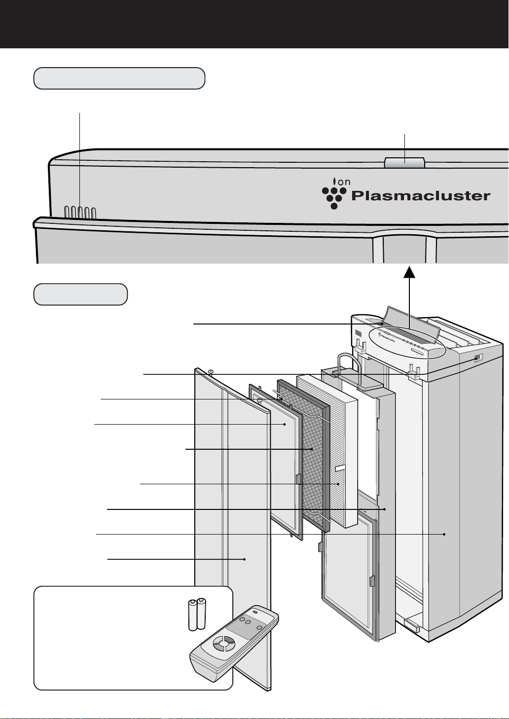
MAIN UNIT DISPLAY
Dust Sensor
FRONT
Operation Panel (refer to E-6. )
Main Power Switch
Plasmacluster Lamp
Press the Plasmacluster Select Button on the Main unit
or Remote Control to select Plasmacluster Ion Mode.
Filter Fixes
Pre-Filters
Active Carbon Filters
Microbial Control Filters
HEPA Filters (white)
Filter Frame
Main unit
Front Panel
(Front:black)
(Back:white)
ACCESSORIES
Battery (R6(AA) battery X 2)
Remote Control (1 unit)
Phillips screwdriver (1 unit)
Anti-toppling kit (1 unit)
Metal fittings (2 units)
Operation Manual
E-4
Page 7
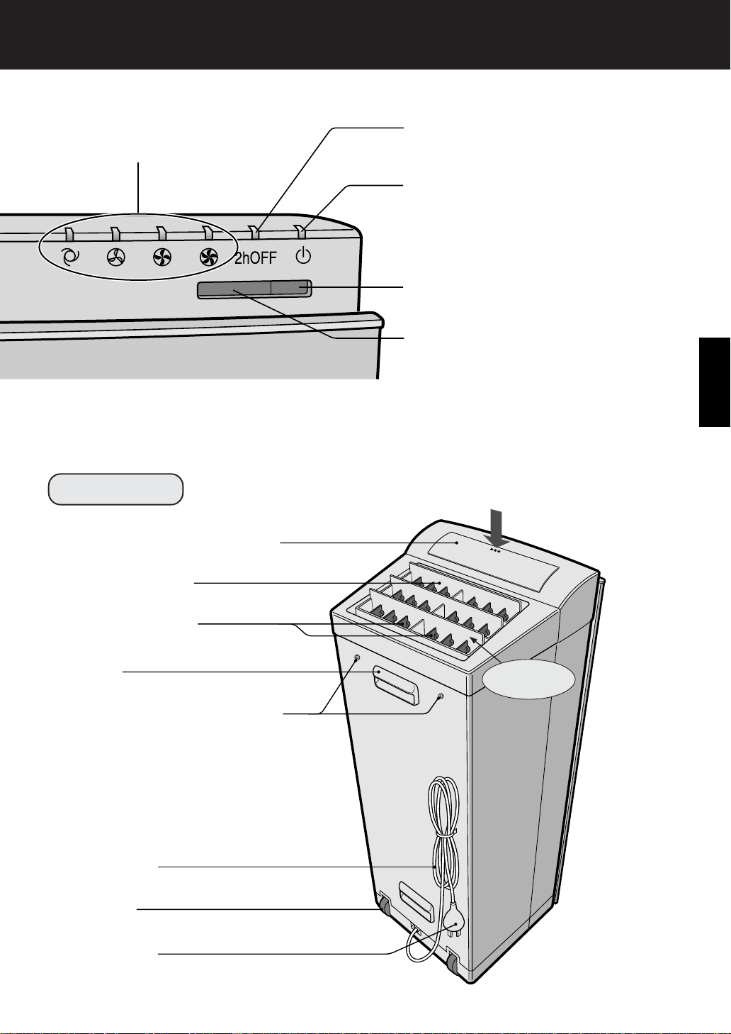
Fan Level Lamps
2-hour OFF Timer Display Lamp
set pressing the 2-hour OFF Timer Button on the Main unit or Remote Control.
Power Lamp
Lights up in red when the Main Power
Switch is turned on. Lights up in green
when the ON/OFF Button is pressed or
the Remote Control is used to start operation.
Odour Sensor
Remote Control Receiver
ENGLISH
BACK
Cover for the operation area
Movable Louvers
Left/right Louvers
Handle
Screws for attaching the antitopple chains
Power Cord
How to open the cover
(Press)
Air Outlet
Casters
Power Plug
E-5
Page 8
PART NAMES
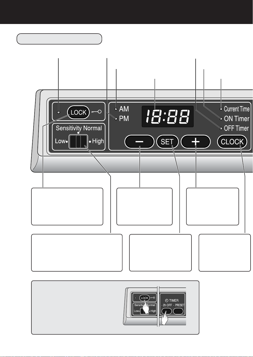
OPERATION PANEL
Lock Lamp
LOCK Button
All other buttons along this
operation panel are disabled
when this LOCK Button is
pressed. (Refer to E-17)
PM Lamp
AM Lamp
-
Reverses the time
during setting.
(Refer to E-12,18)
Button
Digital Display
OFF Timer Lamp
ON Timer Lamp
Current Time Lamp
Button
+
Forwards the time
during setting.
(Refer to E-12,18)
Sensor Sensitivity Select Switch
Switches sensor response between
‘High’, ‘Sensitivity Normal’, and ‘Low’.
(Refer to E-17)
Filter Reset
Press the LOCK Button and 2h OFF
Timer Button at the same time for
three seconds.
(Refer to E-23)
SET Button
Sets up the current time
and the on/off timers.
(Refer to E-12,18)
E-6
CLOCK Button
Sets up the current
time and the on/off
timers.
(Refer to E-12,18)
Page 9
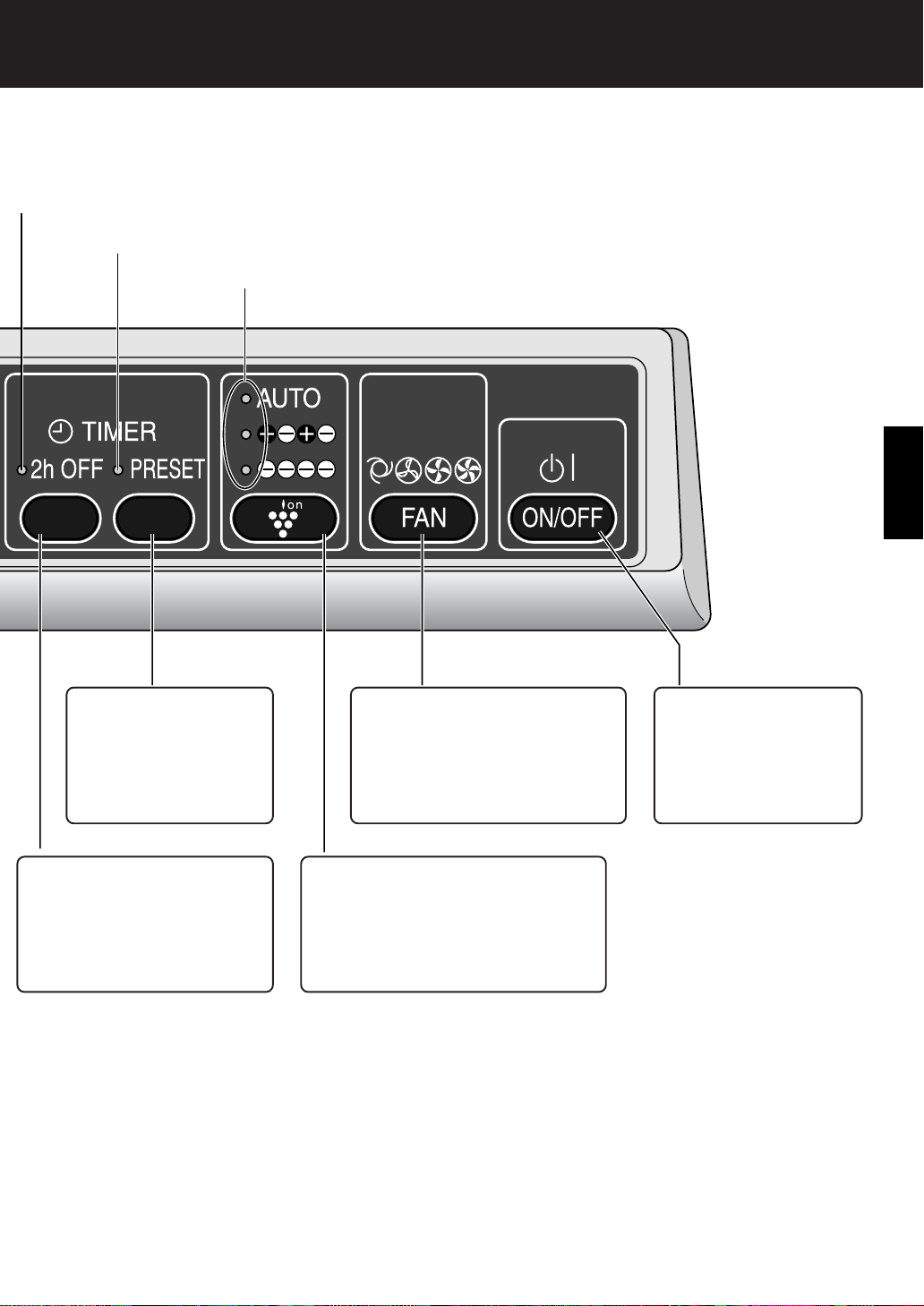
2-hour OFF Timer Lamp
PRESET Lamp
Plasmacluster Select Lamp
ENGLISH
PRESET Button
Sets up and cancels
the on/off timer for 24
hours.
(Refer to E-18)
2-hour OFF Timer Button
Sets up and cancels the on/
off timer for 2-hours off.
(Refer to E-17)
Fan Level Select Button
Set fan level between ‘Silent’,
‘Medium’, ‘High’, and ‘Auto’.
(Refer to E-14,18)
Plasmacluster Select Button
Switches between Plasmacluster
Ion Modes. (Refer to E-15)
ON/OFF Button
Used to turn the unit
on/off. (Refer to E-14)
E-7
Page 10

INSTALLATION
WARNING FOR INST ALLATION
• Do not attempt install the unit by yourself. Incorrect work will cause electric shock, fire etc.
Consult your dealer or other qualified service
personnel for the installation of the unit.
NOTE
• The anti-toppling kit must be attached to ensure safety.
INSTRUCTIONS
• Where the back of the air purifier is closest to
the wall, a mark is likely to result after a while,
so it is recommended that a protective vinyl
sheet or suchlike be attached to the wall.
• Please select a strong site to install the system, such as beside a stable pillar and sash
bar.
• Please contact professionals for installation on
weak partitions or concrete wall.
ANTI-TOPPLING KIT
PREPARATION
Remove the two small screws from the
1
Main unit, and
reattach with the
two Chains
Spring washer
Small screw
Decide on the installation position.
2
Please ensure a gap from the back, left and right
walls as indicated below.
Decide on an appropriate chain length,
3
and cut the Chain to the required length
using pliers or
suchlike.
Clasp
60 cm or more
10 cm or more
60 cm or more
Chains (with a clasp at one end)
(30cmX2)
Clasps
(X2)
Wood screws
(30mmX2)
Fisher plugs
(X2)
Metal fittings
(X2)
10 cm or more
Cut the chain to the
appropriate length.
IF THE PILLAR IS NARROW
Required length
Chain length
should be
decided to
enable setting
as shown in
the illustration.
Attach the Clasp to the Chain.
4
Open the Clasp, and in-
1
sert the last sphere on
the chain through the
hole.
2 Slide the sphere to the
end, and close the
Clasp.
Pillar
10 cm or
more
E-8
Page 11

INSTALLATION AGAINST WOODEN PANELLING
IN THE EVENT THAT THE
SCREWS CANNOT BE APPLIED
Insert the Wood screw , and Screw
1
the Clasp together into the Panel.
NOTE
If the surface is plasterboard,
please install the system
against a stable pillar to which
the plasterboard is attached.
INSTALLATION AGAINST AN ALC, CONCRETE, BRICK, OR MORTAR WALL
Drill a hole on the wall.
1
Use a drill suited to the material of the wall,
and make a hole 5 mm in diameter and at
least 35 mm deep.
ø5mm
35mm
INSTRUCTION
Please ensure the wall, pillar, or sash bar
is at least 35 mm thick before installation.
Insert the Wood screw through
2
the Clasp of the Chain, and into
the mouth of the Fisher plug to a
depth that it is secure.
DIRECTLY T O A RETAINING WALL
Clean the surface to be attached to.
1
Ensure that the surface is not greasy.
Attach the Metal fitting to the wall
2
using the double-side tapes on
the back.(2 pieces)
Peel off the
cover sheets.
Insert the small screw enclosed
3
with the Metal fitting through the
Clasp of the Chain, and fasten it
up to the Metal
fitting.(2 pieces)
Clasp
Small screw
NOTES
• Please use a flat wall surface for such installation.
• Please carefully remove any oil, moisture, and
dust from the wall surface before installation.
• Please attach the system tightly to the wall
by applying pressure.
• It takes a while for the adhesive on the tape
to set, so please do not exert undue loads on
the tape for a couple of hours.
ENGLISH
Wood screw
Fisher plug
Insert the Fisher plug firmly into
3
the wall.
Screw in the Screw.
4
Clasp
SETTING UP THE UNIT IN AN APPROPRIA TE POSITION
Adjust the foot to ensure stability.
Front Panel
Adjust the foot to ensure
NOTE
• Please ensure the Chain has enough slack
to prevent it being fully extended or pulledout when the unit is set up.
E-9
stability.
Main unit
20mm
Page 12

PREPARATION
FILTER INSTALLATION
CAUTIONS
• If you push the Front Panel,
the Main unit will be broken.
• Be sure to remove the Power Plug from the wall outlet.
Be sure to remove the power plug from the wall outlet.
• Do not loosen the screws
which hold the Fan Guards.
To maintain the quality of the filters, they
are placed in the Main unit within plastic
bags. Be sure to remove the filters from
the plastic bags before using the unit.
1
Filter Removal
Confirm to remove the Power Plug
1
and press the Main Power Switch at
the front side.
Extract the handles at the top and bot-
2
tom of the Filter Frame, pull them out,
and remove the Filter Frame from the
Main unit.
NOTE
Fan Guards
Press
Handle
Pre-Filter
Tabs (X4)
Two filters (top and bottom) are attached to the
Filter Frame. After removal, lay the Filter Frame
flat with the handles facing upwards, and replace
the filters.
Unhook the four tabs on the Pre-Fil-
3
ter , and remove the Filter Fixers. (Two
each top and bottom)
Extract the Active Carbon Filter (black
4
(back: white)) and HEP A Filter (white).
(One each top and bottom)
Remove the Active Carbon Filters
5
(black,white) and HEP A Filter from the
plastic bags.
E-10
Filter fixers
Deodorizing Filter (Front: black)
Microbial Control Filter (Back: white)
HEPA Filter
Filter Frame
Page 13

ATTACHING THE FILTER, FILTER FRAME, AND FRONT PANEL
HEPA Filter (white)
Active Carbon Filter (Front: black)
1
Filter Installation
After the HEPA Filters are re-
1
moved from the plastic bag, place
it within the Filter Frame with the
“FRONT” sign facing up.
(See the diagram to the right.)
Ensure that the filters are installed correctly.
Do not install the filters backwards or the
unit will not operate properly.
After removing the Active Carbon
2
Filters from the plastic bag, and
place it over the HEP A Filter with
the black side facing up. (One
each top and bottom)
Attach it with the ‘removal tags’
protruding from the Filter
Frame.
Insert the Filter Fixers into their
3
sockets. (T wo each top and bottom)
Filter Frame
Removal tag
Removal
tags
Filter Fixers
Tabs (X4)
Microbial Control Filter (Back: white)
FRONT
Sockets
Square
Notches
ENGLISH
Insert the four tabs on the Pre-
4
Filter into the Square Notches in
the Filter Frame. (Two each top
and bottom)
Fill in the usage start date on the
5
Date Label, which can be found
on upper of the Main unit.
Use the date as a guide for your filter replacement period.
Holding the Filter Frame by its
6
handle, secure it to the Main unit.
Recess both the top and bottom handles
into the Main unit.
Insert the two Protruding Catches
7
located on the back of the Front
Panel into their housings on the
Main unit, and affix the Front
Panel to the Main unit using the
Top Screws (one each left and
right).
Date Label
Protruding Catches
Housings
Back of the front panel
Phillips screws
Front Panel
E-11
Page 14

PREPARATION
SETTING UP THE CURRENT TIME
Insert the Power Plug into the outlet.
1
Turn on the Main Power Switch.
2
The Power Lamp is lit red and the digital display blinks.
NOTE
The current time must be set up while the unit
is non-operational. It cannot be set up during
operation.
Colon
Press the SET Button.
3
The Colon in the middle of the Digital Display stops blinking, and the indicated current time blinks.
Press the + Button or - Button.
4
Set up the current time while observing the Digital Display.
• The time advances by one minute with each press of the + Button, and goes back
by one minute with each press of the - Button.
• This process will increase in speed if the relevant button is pressed continuously.
Press the + Button or
If the colon starts blinking again, repeat this operation from Step 3.
• The a.m. and p.m. settings must also be set correctly.
Press the SET Button.
5
The colon in the middle of the Digital Display starts blinking, and the clock starts
running.
Button while the colon is not blinking (about 60 seconds).
-
E-12
Page 15

INSERTING BATTERIES IN THE REMOTE CONTROL
Remove the Back Cover
1
Press and slide the back cover to remove.
Insert batteries
2
Insert batteries with and as
shown below.
Close the Back Cover
3
ENGLISH
Battery Information
• The battery life is about 1 year.
• Replace the batteries when the Remote Control becomes inoperative.
• Incorrect usage of the batteries may cause battery fluid leakage and/or
damage. Take care of the following when handling:
• When replacing the batteries, replace both batteries with new ones of
the same type. (Use 2 R6(AA) manganese batteries.)
• When not using the unit or Remote Control for an extended period,
remove the batteries. (This prevents malfunction of the Remote Control from battery fluid leakage.)
*The batteries of the accessory are for initial use only and may be de-
pleted within 1 year.
REMOTE CONTROL USE
• Operate with the Remote Control facing the Main
unit (Receiver).
• The signal range is about 7m (front).
• Make sure there are no objects blocking the path
of the signal.
•A beep sound will be heard from the Main unit
when a signal is received.
NOTE
•Avoid dropping or damaging on the Remote Control. In addition, be sure the Remote Control
avoids moisture or place in direct sunlight or near
an electric heater, etc., otherwise a malfunction
may occur.
E-13
Receiver
Transmitter
Page 16

OPERATION
MAIN UNIT OPERATION
Plasmacluster Lamp
1
Press the Main
1
Power Switch.
The Power Lamp is lit red.
Press the ON/OFF
2
Button
The Power Lamp is lit
green, and automatic operation or operation at the
preset flow rate starts.
OPERATION
2
The fan level is switched as follows every time
the Fan Level Select Button is pressed.
AUTO
Silent
Medium
High
E-14
FAN LEVEL SET UP
The fan level is automatically switched
between the five levels depending on
the amount of impurities in the air. The
sensors detect the impurities for efficient air purification.
The unit will operate quietly using minimal air intake.
Operates on the Medium fan level setting.
Operates on the High fan level setting.
Page 17

3
2
Main Power Switch
It is on the right side of main unit.
Power Lamp
1
ENGLISH
3
The Plasmacluster Ion Mode is switched as follows every time the
Plasmacluster Select Button is pressed.
SET UP THE PLASMACLUSTER ION MODE
The unit will switch between Clean Mode and Ion Control Mode
Auto
Clean
Ion Control
Off
automatically depending on the amount of impurities in the air detected by the dust and odour sensors. Clean Mode operation will
operation for about 1 minute when the Auto function is selected.
The unit will constantly operate in Clean Mode. Clean Mode is
effective for reducing some airborne mold. (Plasmacluster Lamp is
blue)
The unit will constantly operate in Ion Control Mode. Ion balance
is maintained in the room by increasing the ration of negative ions.
(The Plasmacluster Lamp is green)
The generation of ions will cease and the Plasmacluster Lamp will
go out.
E-15
Page 18

OPERATION
REMOTE CONTROL OPERATION
• Before using the Remote Control, turn the Main Power Switch
on.
• When you press the POWER ON/OFF Button, a short beep
will sound and operation will start. It automatically goes to
the last operation mode.
•To stop operation, press the POWER ON/OFF Button again.
A long beep will sound and operation will stop.
POWER ON/OFF Button
A short beep will signal that
the unit is on and a long beep
means that the unit is off.
2h OFF
AUTO (Fan Level) Button
The fan level switches automatically depending on the
amount of impurities in the air.
Operations available
with Remote Control
•
AUTO
•
MANUAL
• 2-hour OFF Timer
Plasmacluster Ion Mode Selections
•
AUTO Plasmacluster Ion Mode
• Clean Mode
• Ion Control Mode
•
OFF
Transmitter
2-hour OFF Timer Button
Pressing this button sets the 2hour OFF Timer. Press it again
to cancel the setting.
MANUAL (Fan Level) Button
The fan level can be switched
between Silent, Medium and
High.
Plasmacluster Ion Mode Selections
AUTO Plasmacluster Ion
When pressed the unit will switch between
Clean Mode and Ion Control Mode automatically depending on the amount of impurities in
the air detected by the dust and odour sensors.
Clean Mode operation will operate for about 1
minute when the AUTO function is selected.
Ion Control
The unit will constantly operate in Ion Control
Mode. Ion balance is maintained in the room
by increasing the ratio of negative ions.
(Plasmacluster Lamp is green)
Plasmacluster
AUTO
OFF
Clean
When pressed the unit will constantly operate in Clean Mode.
Clean Mode is effective for reducing some airborne mold.
(Plasmacluster Lamp is blue)
OFF
The generation of ions will cease
and the Plasmacluster Lamp will go
out.
If the room smells especially moldy, operate the unit in Clean Mode.
E-16
Page 19

CONVENIENT FUNCTIONS
2-HOUR OFF TIMER
Use this function to stop operation automatically after two hours.
Press the 2-hour OFF Timer Button during operation.
1
•A ‘beep’ sound indicates that the 2-hour OFF T imer has been turned
on. The unit will turn off about two hours after the button was pressed.
Deactivating 2-hour OFF Timer
Press 2-hour OFF Timer Button
1
•A ‘beep’ sound indicates that the 2-hour OFF T imer has been turned
off. The 2-hour OFF Timer is then deactivated
NOTE
If the PRESET Timer has been activated, it will then be deactivated and the 2-hour OFF
Timer takes priority.
2h OFF
2h OFF
ENGLISH
LOCK FUNCTION
Use the LOCK Button to disable all the other operating buttons on the Main
unit.
Press the LOCK Button for one second.
1
• The Lock Lamp is lit. All displays on the operation panel are turned
off except the 2-hour OFF Timer Lamp and the PRESET Lamp.
How to unlock
Press the LOCK Button for about three seconds.
1
• The Lock Lamp is turned off, and the lock setting is deactivated.
NOTES
• While the lock function is activated, all functions except the Main Power Switch and Sensor
sensitivity Select Switch and Lock Button are disabled. The Operation Lamps are on in
accordance with the operational status.
• Operation is possible using the Remote Control.
SENSITIVITY SWITCH
The sensitivity of the Odour Sensor and the Dust Sensor can be adjusted. The
factory setting is Normal, so please switch it in accordance with the status of
the room environment.
NOTE
• It can be switched regardless of whether
the Main unit is locked or not.
E-17
Page 20

CONVENIENT FUNCTIONS
PRESET TIMER
This function repeats the On and Off operations at the same time every day.
Up to three pairs of on and off times can be set.
If a pair of on and off times is set, the PRESET Timer function can be activated.
NOTES
Setting up the ON Time.
1
1
Press the CLOCK Button, and turn on the ON Timer Lamp.
2
Press the SET Button.
• The ON Timer Lamp blinks and the ON Timer set-up mode is activated.
3
Set the ON Time using the + and
4
Set the operating mode using the Plasmacluster Select Button and
Fan Level Select Button.
5
Press the SET Button.
• The ON Timer Lamp lights up indicating that set-up is complete.
Setting up the OFF Time.
2
1
Press the CLOCK Button, and turn on the OFF Timer Lamp.
2
Press the SET Button.
• The OFF Timer Lamp blinks and the OFF Timer set-up mode is
activated.
3
Set the OFF Time using the + and
4
Press the SET Button.
•The OFF Timer Lamp lights up indicating that set-up is complete.
• Please set the timer after confirming that the current time setting is correct.
• The timer cannot be set until the clock is set.
• The preset timer function does not work until both on time and off time are
set.
• Please set the PRESET Timer while the unit is stopped. Setup is not possible while it is in operation.
Buttons.
-
Buttons.
-
NOTE
Setting up the PRESET Time.
3
Once the on and off times are set, they must be activated by pressing the PRESET Button
1
Press the PRESET Button while the unit is stopped.
• The Preset Lamp turns on indicating that the Preset Timer is set up.
Automatically confirmed if about 60 seconds pass without the SET Button
being pressed. About eight seconds after the OFF Timer lamp turns off, it
automatically returns to the current time.
.
PRESET
Deactivating the Preset Timer.
Press the PRESET Button.
1
• The PRESET Lamp turns off indicating that the PRESET Timer is cancelled.
NOTES
• When the Main Power Switch is turned off, the PRESET Timer is cancelled. Even if the Main
Power Switch is turned on again, the status remains cancelled. However, the times that have
been set are still memorized.
• Three pairs of ON and OFF Times can be set, but in the event of any duplication, is shown on
the Digital Display, and set-up is not possible.
E-18
PRESET
Page 21

SWITCHING THE DISPLAY
Regardless of the operational status, the current time and three pairs of preset timer set-up times are displayed on the Digital Display area by pressing
the time button.
The Digital Display is switched as follows every time the CLOCK
Button is pressed.
Current Time
"beep"
ON Time 1
"beep"
OFF Time 1
"beep,beep"
ON Time 2
"beep,beep"
OFF Time 2
"beep,beep,beep"
ON Time 3
"beep,beep,beep"
OFF Time 3
"beep"
NOTES
• If the time has not been set, bars
are displayed.
• When an on or off time is left displayed for about eight seconds, the
display reverts to the current time.
• While the unit is stopped, if the
SET Button is pressed when an on
or off time is displayed, the adjustment mode for the displayed time
is activated.
• While the unit is stopped, if the
SET Button is pressed when the
current time is displayed, the adjustment mode for the current time
is activated.
ENGLISH
How to cancel the times set for the Preset Timer.
Press the CLOCK Button, and display the ON Time
1
to be cancelled.
• The ON Timer Lamp is turned on.
Press the SET Button.
2
• The ON Timer Lamp blinks.
Press the CLOCK Button
3
• The Digital Display area shows a bar.
Press the SET Button
4
• Cancellation is validated.
When an On time is cancelled, its corresponding Off time is auto-
matically cancelled as well.
E-19
Page 22

OPERATION GUIDE
ODOUR SENSOR GUIDELINES
• The Odour Sensor responds to cigarette and pet odours, as well as other scents such as
Insecticide, cosmetics, spray, alcohol, or sudden changes in temperature or humidity.
• When the unit is in Auto Mode and room is in a closed environment, the sensor will respond to
some odours by increasing the air flow. If you do not desire increased air flow, please adjust
the sensitivity of the sensor.
DUST SENSOR GUIDELINES
• The Dust Sensor detects particles in the air, such as cigarette smoke and house dust or
pollen.
• Compared with cigarette smoke, the amount of dust released when cleaning your carpet is so
small that it may not be detected by the Dust Sensor.
FILTER RESET
• Once the Active Carbon Filter has been replaced, connect the Power Cord to the outlet and
press the LOCK Button and 2-hour OFF Timer Button at the same time for three seconds. It
means Filter Reset.
Once Filter Reset has been activated, you will hear a beep sound that means that the unit has
been reset. If a Fan Level Lamp had been blinking, it will now stop blinking automatically.
SPECIFICATIONS
Model
Power supply
Fan Level
Operation
* The applicable floor surface area for when operating the unit in High fan level.
(JEM 1467, The Japan Electrical Manufactueres’ Association)
Fan Level Adjustment
Rated Power
Fan Level
Applicable Floor Surface
Cord Length
Dimensions
Weight
High
46 W
480m3/hour
360mm(W)x342mm(D)x999mm(H)
FU-800-J
220-240V 50Hz
Medium
19 W
240m3/hour
~61m2*
3.0m
28kg
92m3/hour
Silent
10 W
About the reduction of standby power
In order to operate the electrical circuits while the Main Power Switch is turned on, this product
consumes about 3.7W (2.3W:while LOCK function is activated) of standby power.
For energy conservation, turn off the Main Power Switch.
E-20
Page 23

CARE AND MAINTENANCE
(To maintain optimum performance of this product, please clean the unit including its sensors and
filters periodically.)
When cleaning the unit, be sure to unplug the Power Plug and, never handle the plug with wet
hands. Electrical shock and/or bodily injury may occur as a result.
MAIN UNIT
To prevent dirt or stains on the
main unit, clean as often as necessary. If stains are allowed to
remain, they may become hard
to clean.
Wipe with a dry soft cloth
For stubborn stains or dirt, use
a soft cloth dampened with
warm water 40°C or less.
Do not use volatile fluids
Benzene, paint thinner, polishing powder, etc., may damage
the unit surface.
Do not use detergents
Detergent ingredients may damage the unit surface.
Keep the unit dry
Never apply water to the unit.
PREPARATION
Remove the Front Panel before
cleaning the Dust Sensor, Odour
Sensor, and filters.
DUST SENSOR ODOUR SENSOR
The maintenance cycles of Odour and Dust Sensor
are every 3 months.
The sensitivity of the sensors will become unstable
if the Odour or Dust Sensor is dirty or blocked. Please
clean the parts as outlined below.
DUST SENSOR
Vacuum off dust from the Dust Sensor area using a
vacuum cleaner nozzle.
ENGLISH
CAUTION
Care must be taken not to damage the Main unit
with the nozzle while cleaning.
Dust Sensor area
Remove the front panel.
Loosen the two screws at the top
left and right of the Front Panel
using a Phillips (+) screwdriver,
then remove the Front Panel.
Phillips screws
Front Panel
CAUTION
If the Front Panel is removed after loosing the Screws, the Front
Panel may fall, and injure some
one and some parts may be broken.
ODOUR SENSOR
Vacuum off dust from the Odour Sensor area using a vacuum cleaner nozzle.
CAUTION
Care must be taken not to damage the Main unit
with the nozzle while cleaning.
Odour Sensor area
E-21
Page 24

CARE AND MAINTENANCE
FILTER CLEANING
The care cycles of filters are once three
months
Extract the handles at the top
1
and bottom of the Filter Frame,
pull them out, and remove the
Filter Frame from the Main unit.
NOTE
Two filters (top and bottom) are attached
to the Filter Frame. After removal, lay
the Filter Frame flat with the handles fac-
ing upwards.
Handle
SETTING THE FRONT PANEL
Insert the two protruding catches
located on the back of the Front
Panel into their housings on the
Main unit, and affix the Front Panel
to the Main unit using the top
screws (one each left and right).
Housings
Protruding catches
Back of the
Front Panel
Clean the top surface of the Pre-
2
Filter lightly with a vacuum
cleaner.
Pre-Filter
NOTE
The HEP A Filter and Active Carbon Filter
are damaged easily. Do not bring it into
direct contact with the nozzle of a vacuum
cleaner.
They should never be washed with
water.
Holding the Filter Frame by its
3
handle, secure it to the main
unit.
Recess both the top and bottom handles into the Main unit.
Phillips Screws
Front Panel
E-22
Page 25

FILTER REPLACEMENT GUIDELINES
The filter replacement period is indicated by blinking of a Fan Level Lamp.
(If the unit is constantly operated at High fan level, the shortest period is 125 days. Accumulated operating hours differs depending on fan level in which product is used.)
• The operation hours are saved in memory even when removing the Power Plug.
• The indication is to be used only as a guide.
• If dust or odours cannot be removed easily, replace the filters.
Guide for replacing the filters
• HEPA Filter About 1 year after opening
• Active Carbon Filter About 1 year after opening
• The replacement period is based on the condition that smoking 10 cigarettes per day and the
dust collection/deodorization ability is reduced by half than that of new filters.
(JEM1467, The Japan Electrical Manufacturers’ Association)
• The replacement period differs depending on the operation hours and location of installation.
• Depending on the usage environment, odour may be noticed from the Air Outlet in several
months. (For understanding the product. Refer to page E-1)
REPLACING THE FILTERS
Remove the Front Panel. (Refer to E-21 “PREPARATION”)
1
See page E-10, E-11 for directions on Filter installation when replac-
2
ing.
ENGLISH
Fill in usage start date of the filters on the Date Label, which can be
3
found on upper of the Main unit.
Be sure to press the LOCK Button and 2h-OFF Timer Button at the
4
same time for three seconds with the Power Cord connected to the
outlet an Main Power Switch turned on. A short beep will be heard and
the operation hours stored in the memory will be reset. If a Fan Level
Lamp had been blinking, it will now stop blinking.
Replacement filters
• HEP A Filter : PFIL-A059KKEZ
• Active Carbon Filter : FFIL-A006KKKZ
Please ask for replacement filters
at your dealer of purchase.
Cautions concerning the disposal of filters
Please dispose of replaced filters according to the
local disposal laws and regulations.
HEPA Filter materials:
• Filter: Polypropylene
• Frame: Polyester
Active Carbon Filter materials:
• Deodorizer: Activated charcoal
• Frame: Card board
Press the button for three seconds
E-23
Page 26

TROUBLESHOOTING
Before calling for repair, check the symptoms below for possible remedies, since the problem may
not be a malfunction of the unit.
SYMPTOM
A Fan Level Lamp blinks.
The Remote Control does
not work
Odour and dust cannot be
removed easily
The Plasmacluster Lamp
blinks
The Plasmacluster Lamp remains green (blue) and does
not change
A sound is
heard from the
unit
A sound “tick, tick, tick” is
sometimes heard from the unit
and is not sometimes heard.
The discharged air smells
The unit does not operate even
when cigarette smoke is in
the air
Click, click
Tick, tick, tick
REMEDY (not a malfunction)
• Blinking of a Fan Level Lamp shows the filter replacing time.
• After replacing filters, turn the Main Power Switch on, and press the
LOCK Button and 2-hour OFF Timer Button at the same time for
three seconds. (Refer to E-23)
• Have the batteries been depleted?
• Are the batteries inserted correctly?
• Is a fluorescent lighting in the room flickering due to service life?
(Refer to E-3, E-13)
• Are the filters heavily soiled? (Refer to E-23)
• Is the Digital Display indicating the error?
(Refer to ERROR DISPLAY)
• When in Clean Mode (or Ion Control Mode), the Plasmacluster Lamp
colour will not change.
• Is the opening of the Odour Sensor blocked or the Dust Sensor
clogged? (Refer to E-21)
• Clicking sound is emitted when the unit is in Ion Control Mode.
If the sound is irritating, stop the generation of ions.
•Ticking sound is emitted when the unit is generating ions. If the sound
is irritating, stop the generation of ions. (Refer to E-15)
•A sound is sometime low, loud or not at all. But the effect of the
Plasmacluster ion is the same.
• Check to see if the filters are heavily soiled.
Replace filters. (Refer to E-23)
•Very low concentration of ozone generated by the Plasmacluster
ion generate may have a odour.
This is harmless and will not affect the human body . Also, the ozone
will break down quickly and will not accumulate in the room environment.
• Is the unit installed in a location that is difficult for the sensors to
detect cigarette smoke?
• Are the Odour or Dust Sensor openings blocked or clogged?
(In this case, clean the Sensors.) (Refer to E-21)
ERROR DISPLAY
DIGITAL DISPLAY
Disconnection or failure
with the top fan motor.
Disconnection or failure
with the bottom fan motor.
Disconnection or failure
with Plasmacluster unit.
DETAILS
ACTION REQUIRED
Operation is suspended.
• When the ON/OFF Button is pressed, the error display is cancelled, but if an error is indicated again,
please contact the dealer from whom you purchased the equipment.
Operation is possible, but no Plasmacluster
ions are generated.
• When the ON/OFF Button is pressed, the error display is cancelled, but if an error is indicated again,
please contact the dealer from whom you purchased the equipment.
E-24
Page 27

ENGLISH
Page 28

SHARP CORPORATION
OSAKA, JAPAN
TINS-A103KKRZ 03LK 1
 Loading...