

Page 1
SERVICE MANUAL
No. 00ZFO6600USME
FACSIMILE
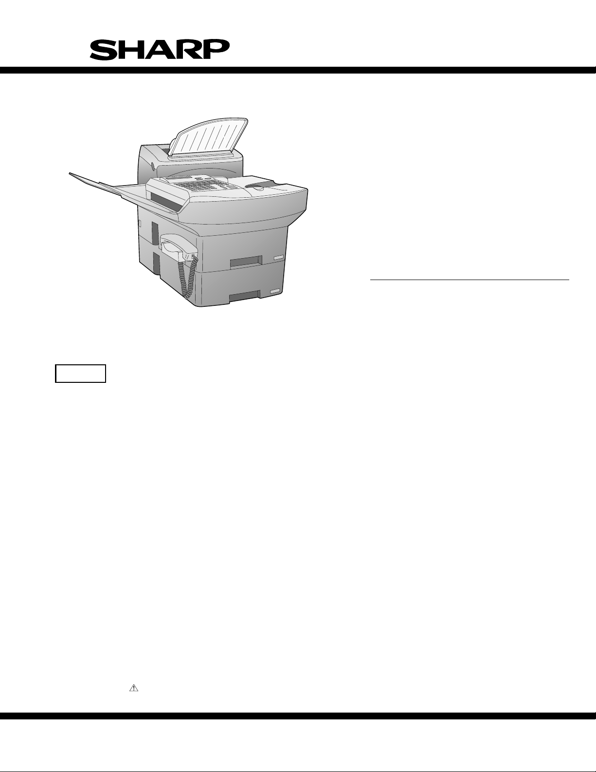
MODEL FO-6600
FO-6600U
CAUTION
This laser printer is a class 1 laser product that complies with 21CFR 1040.10 and 1040.11 of the CDRH standard. This means that
this machine does not produce a hazardous laser radiation. The use of controls, adjustments or performance of procedures other
than those specified herein may result in hazardous radiation exposure.
This laser radiation is not a danger to the skin, but when an exact focusing of the laser beam is achieved on the eyes retina, there is
danger of spot damage to the retina.
The following cautions must be observed to avoid exposure of the laser beam to your eyes at the time of servicing.
1) When a problem in the laser optical unit has occurred, the whole optical unit must be exchanged as a unit, not an individual part.
2) Do not look into the machine with the main switch turned on after removing the toner/developer unit and drum cartridge.
3) Do not look into the laser beam exposure slit of the laser optical unit with the connector connected when removing and installing
the optical system.
4) The cover of Laser Printer Unit contains the safety interlock switch.
Do not defeat the safety interlock by inserting wedges or other items into the switch slot.
Laser Wave Length : 770-810 mm
Laser Pulse Times : 49.2 µs
Laser Output Power : 0.5 mW
Parts marked with " " is important for maintaining the safety of the set. Be sure to replace these parts with specified ones for maintaining the safety and performance of the set.
This document has been published to be used
SHARP CORPORATION
1 - 1
for after sales service only.
The contents are subject to change without notice.
Page 2

FO-6600U
CONTENTS
CHAPTER 1. GENERAL DESCRIPTION
[1] Specifications . . . . . . . . . . . . . . . . . . . . . . . . . . . . . . . . . . . . . . . . . . . . . . . . . . . . . . . . . . . . . . . . . . 1-1
[2] Operation panel . . . . . . . . . . . . . . . . . . . . . . . . . . . . . . . . . . . . . . . . . . . . . . . . . . . . . . . . . . . . . . . . 1-2
[3] Transmittable documents . . . . . . . . . . . . . . . . . . . . . . . . . . . . . . . . . . . . . . . . . . . . . . . . . . . . . . . . . 1-4
[4] Installation . . . . . . . . . . . . . . . . . . . . . . . . . . . . . . . . . . . . . . . . . . . . . . . . . . . . . . . . . . . . . . . . . . . . 1-5
[5] Quick reference guide . . . . . . . . . . . . . . . . . . . . . . . . . . . . . . . . . . . . . . . . . . . . . . . . . . . . . . . . . . 1-10
CHAPTER 2. ADJUSTMENTS
[1] Adjustments . . . . . . . . . . . . . . . . . . . . . . . . . . . . . . . . . . . . . . . . . . . . . . . . . . . . . . . . . . . . . . . . . . . 2-1
[2] Diagnostics and service soft switches . . . . . . . . . . . . . . . . . . . . . . . . . . . . . . . . . . . . . . . . . . . . . . . 2-2
[3] Troubleshooting . . . . . . . . . . . . . . . . . . . . . . . . . . . . . . . . . . . . . . . . . . . . . . . . . . . . . . . . . . . . . . . 2-37
[4] Error code table . . . . . . . . . . . . . . . . . . . . . . . . . . . . . . . . . . . . . . . . . . . . . . . . . . . . . . . . . . . . . . . 2-42
[5] Overseas communication mode . . . . . . . . . . . . . . . . . . . . . . . . . . . . . . . . . . . . . . . . . . . . . . . . . . . 2-43
CHAPTER 3. MECHANICAL DESCRIPTION
[1] Mechanical description . . . . . . . . . . . . . . . . . . . . . . . . . . . . . . . . . . . . . . . . . . . . . . . . . . . . . . . . . . . 3-1
[2] Printer description . . . . . . . . . . . . . . . . . . . . . . . . . . . . . . . . . . . . . . . . . . . . . . . . . . . . . . . . . . . . . . 3-3
[3] Disassembly/assembly procedures . . . . . . . . . . . . . . . . . . . . . . . . . . . . . . . . . . . . . . . . . . . . . . . . 3-10
CHAPTER 4. DIAGRAMS
[1] Block diagram . . . . . . . . . . . . . . . . . . . . . . . . . . . . . . . . . . . . . . . . . . . . . . . . . . . . . . . . . . . . . . . . . 4-1
[2] Wiring diagram . . . . . . . . . . . . . . . . . . . . . . . . . . . . . . . . . . . . . . . . . . . . . . . . . . . . . . . . . . . . . . . . . 4-2
[3] Point to point diagram and connector signal name . . . . . . . . . . . . . . . . . . . . . . . . . . . . . . . . . . . . . 4-3
CHAPTER 5. CIRCUIT DESCRIPTION
[1] Circuit description . . . . . . . . . . . . . . . . . . . . . . . . . . . . . . . . . . . . . . . . . . . . . . . . . . . . . . . . . . . . . . . 5-1
[2] Circuit description of control PWB . . . . . . . . . . . . . . . . . . . . . . . . . . . . . . . . . . . . . . . . . . . . . . . . . . 5-1
[3] Circuit description of line control PWB . . . . . . . . . . . . . . . . . . . . . . . . . . . . . . . . . . . . . . . . . . . . . . 5-19
[4] Circuit description of TEL/LIU1 PWB . . . . . . . . . . . . . . . . . . . . . . . . . . . . . . . . . . . . . . . . . . . . . . . 5-22
[5] Circuit description of TEL/LIU2 PWB . . . . . . . . . . . . . . . . . . . . . . . . . . . . . . . . . . . . . . . . . . . . . . . 5-25
[6] Circuit description of CCD PWB . . . . . . . . . . . . . . . . . . . . . . . . . . . . . . . . . . . . . . . . . . . . . . . . . . . 5-28
[7] Circuit description of operation PWB . . . . . . . . . . . . . . . . . . . . . . . . . . . . . . . . . . . . . . . . . . . . . . . 5-28
[8] Circuit description of power supply PWB . . . . . . . . . . . . . . . . . . . . . . . . . . . . . . . . . . . . . . . . . . . . 5-29
[9] Circuit description of RS232C I/F PWB . . . . . . . . . . . . . . . . . . . . . . . . . . . . . . . . . . . . . . . . . . . . . 5-34
CHAPTER 6. CIRCUIT SCHEMATICS AND PARTS LAYOUT
[1] Control PWB circuit . . . . . . . . . . . . . . . . . . . . . . . . . . . . . . . . . . . . . . . . . . . . . . . . . . . . . . . . . . . . . 6-1
[2] Line control PWB circuit . . . . . . . . . . . . . . . . . . . . . . . . . . . . . . . . . . . . . . . . . . . . . . . . . . . . . . . . . 6-20
[3] TEL/LIU 1, 2 PWB circuit . . . . . . . . . . . . . . . . . . . . . . . . . . . . . . . . . . . . . . . . . . . . . . . . . . . . . . . . 6-28
[4] Power supply PWB circuit . . . . . . . . . . . . . . . . . . . . . . . . . . . . . . . . . . . . . . . . . . . . . . . . . . . . . . . 6-33
[5] Operation panel PWB circuit . . . . . . . . . . . . . . . . . . . . . . . . . . . . . . . . . . . . . . . . . . . . . . . . . . . . . 6-35
[6] CCD PWB circuit . . . . . . . . . . . . . . . . . . . . . . . . . . . . . . . . . . . . . . . . . . . . . . . . . . . . . . . . . . . . . . 6-37
[7] RS232C I/F PWB circuit . . . . . . . . . . . . . . . . . . . . . . . . . . . . . . . . . . . . . . . . . . . . . . . . . . . . . . . . . 6-38
[8] Printer control PWB circuit . . . . . . . . . . . . . . . . . . . . . . . . . . . . . . . . . . . . . . . . . . . . . . . . . . . . . . . 6-40
CHAPTER 7. OPERATION FLOWCHART
[1] Protocol . . . . . . . . . . . . . . . . . . . . . . . . . . . . . . . . . . . . . . . . . . . . . . . . . . . . . . . . . . . . . . . . . . . . . . 7-1
[2] Power on sequence . . . . . . . . . . . . . . . . . . . . . . . . . . . . . . . . . . . . . . . . . . . . . . . . . . . . . . . . . . . . . 7-2
CHAPTER 8. OTHERS
[1] Service Tools . . . . . . . . . . . . . . . . . . . . . . . . . . . . . . . . . . . . . . . . . . . . . . . . . . . . . . . . . . . . . . . . . . 8-1
[2] IC signal name . . . . . . . . . . . . . . . . . . . . . . . . . . . . . . . . . . . . . . . . . . . . . . . . . . . . . . . . . . . . . . . . . 8-7
PARTS GUIDE
1 – 2
Page 3

CHAPTER 1. GENERAL DESCRIPTION
[1] Specifications
FO-6600U
• GENERAL
Applicable telephone line: Public switched telephone network
Compatibility: ITU-T (CCITT) G3 mode
Configuration: Half-duplex, desktop transceiver
Compression scheme: MH, MR, MMR and Sharp special mode
Memory size*: 2 MB (approx. 108 average pages)
Memory option: 1 MB/2 MB/4 MB/16 MB Flash Memory
Scanning method: Flat-bed, solid-state CCD
Resolution: Horizontal:
203 lines/inch (8 dots/mm)
Vertical:
Standard-98 lines/inch
(3.85 lines/mm)
Fine/Halftone-196 lines/inch
(7.7 lines/mm)
Super fine-391 lines/inch
(15.4 lines/mm)
Printing density: Horizontal:
406 lines/inch (16 lines/mm)
Vertical:
391 lines/inch (15.4 lines/mm)
Reception modes: Auto/Manual switching
Modem speed: 33600 bps with automatic fallback to
31200, 28800, 26400, 24000, 21600,
19200, 16800, 14400, 12000, 9600,
7200, 4800, or 2400 bps
Note: Transmission speeds in Super G3
mode may vary due to telephone line
conditions.
Transmission time*: Approx. 3 seconds
Input document size: Automatic feeding:
Width 5.8 to 11.0" (148 to 280 mm)
Length 5.0 to 14.3" (128 to 364 mm)
Manual feeding:
Width 5.8 to 11.0" (148 to 280 mm)
Length 5.0 to 17.0" (128 to 432 mm)
Paper size: Width 8.5" (216 mm)
Length 11-14" (280-356 mm)
Paper capacity: 1150 sheets
Automatic document feeder: 50 documents max.
Effective scanning width: 10.1" (256 mm)
Effective recording width: 8.0" (203 mm)
Copy function: Single/Multi-copy/Sort-copy
(99 copies/page)
Telephone function: Standard (cannot be used if power
fails)
Halftone (gray scale): 64 levels
Power requirements: 120 V AC, 60 Hz
Operating environment: 50-86°F (10-30°C), 20 to 85% RH
Power consumption: Stand-by: 15 W
Maximum: 400 W
Dimensions: Width: 13.8" (351 mm)
Depth: 22.9" (582 mm)
Height: 18.5" (469 mm)
Weight: Approx. 59.8 lbs. (27.1 kg)
• PRINTER SECTION
Type: Desktop, Laser Beam Printer
Print system: Electrostatic Dry Powdered Imaging
System
Exposure system: Laser Diode + Polygon Mirror
Scanning
Resolution: Horizontal: 406 (dot/inch)
Vertical: 391 (dot/inch)
Print speed: 6 pages per minute (Letter size paper)
First print time: Within 19 seconds (face down)
Warming-up time: Within 40 sec.
Operating environment: Temperature: 10-30°C
Humidity: 20-80%RH
Toner cartridge life: 3,700 prints or more (when black-to-
white ratio on print is 4% or less)
Drum cartridge life: 20,000 prints or more (when black-
to-white ratio on print is 5% or less)
* Based on ITU-T (CCITT) T est Chart #1 at standard resolution in Sharp
special mode, excluding time for protocol signals (i.e., ITU-T phase C
time only).
<IMPORTANT PLEASE READ FIRST>
To avoid problems with supplies, please don’t use supplies from other units. Please use new supplies, when supply changes are required.
1 – 1
Page 4
FO-6600U
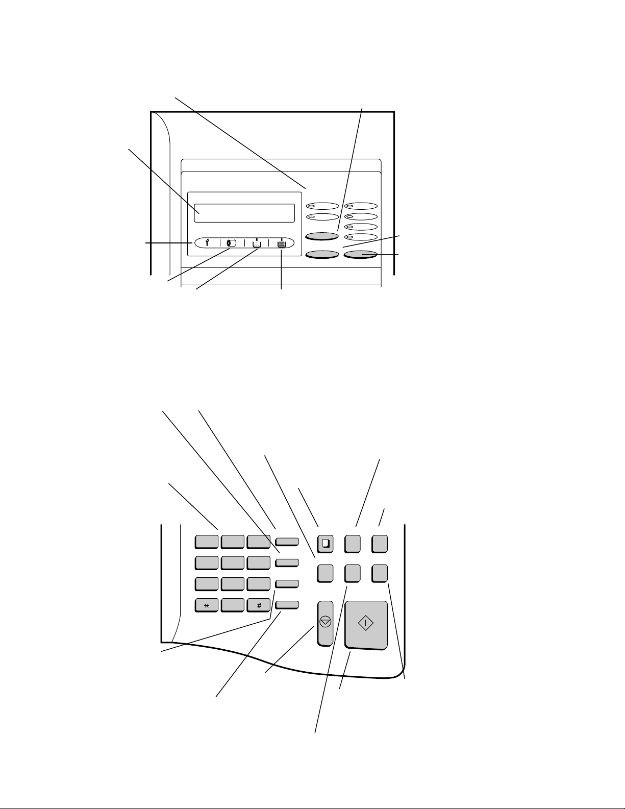
[2] Operation panel (1)
LINE STATUS lights
This LINE-1 lights illuminates
when Line 1 is being used, and
the LINE-2 lights illuminates
when Line 2 is being used.
Display
This displays messages
and prompts during
operation and
programming.
Service indicator
This lights when a
problem occurs which
must be fixed by a
service technician.
Drum cartridge indicator
This blinks when the drum
cartridge nears the end of
its life, and lights steadily
when the drum cartridge
needs replacement.
Toner cartridge indicator
This blinks when toner nears
empty, and lights steadily
when the toner/developer
cartridge needs replacement.
LINE key
Press this key before
dialing to select the line.
LINE-STATUS RESOLUTION
IN USE STANDARD
LINE-2
LINE
CHANGEOVER
FINE
SUPER FINE
HALF TONE
Paper out indicator
This blinks when one of the
paper sources (cassette) is out
of paper, and lights steadily when
all sources are out of paper.
CHANGEOVER key
Three types of information appear in the
display: prompts related to operations you
are performing, information about how the
fax is using the line 1 (transmitting,
receiving, etc.), information about how the
fax is using the line 2. Press this key to
switch through the three types of
information.
RESOLUTION key
Press this key to
adjust the resolution
before sending or
copying a document.
SPEED DIAL key
Press this key to dial
a Speed Dial number.
Telephone dial keypad
(numeric keys)
Use these keys to dial
and program numbers.
REDIAL key
Press this key to automatically
redial the last number dialed.
SPEAKER key
Press this key to dial a
number without picking
up the handset.
Note: This is not a
speakerphone. You must
pick up the handset to
talk with the other party.
FUNCTION key
Press this key to select
various special functions.
BROADCAST key
Press this key to send a
document to a group of
receiving fax machines.
ABC
123
GHI
456
PRS
789
DEF
JKL MNO
TUV WXY
OPER
0
STOP key
Press this key to
stop operations
before they are
completed.
COVER SHEET key
Press this key to include
a cover sheet with a
transmitted document.
COPY key
Press this key to make
a copy of a document.
FUNCTION
SPEED DIAL
REDIAL
SPEAKER
COPY REPORT DOCUMENT
BROADCAST
STOP START
START key
Press this key to
send or receive
a document
REPORT key
Press this key to print out
a report on the transaction
just completed.
DOCUMENT key
Press this key to transmit
a document without
reading it into memory.
COVER SHEET
PRIORITY
PRIORITY key
Press this key when
you want to transmit
a document ahead of
other documents
.
waiting in memory
for transmission.
1 – 2
Page 5
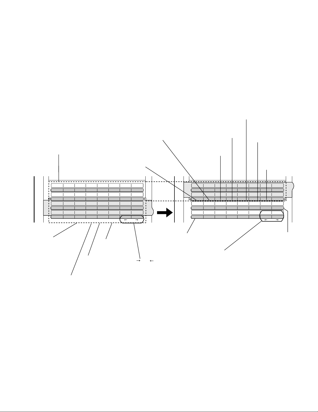
Operation panel (2)
CLEARSPSHIFTSPACE
A
I
Q
Y
B
J
R
Z
C
K
S
D
L
T
E
M
U
F
N
V
G
O
W
H
P
X
01
09
17
25
02
10
18
26
03
11
19
04
12
20
05
13
21
06
14
22
07
15
23
08
16
24
27 28 29 30 31 32
CLEARSPSHIFTSPACE
A
I
Q
Y
B
J
R
Z
C
K
S
D
L
T
E
M
U
F
N
V
G
O
W
H
P
X
33
41
CONTRAST
SEARCH DIAL
34
42
PAGE COUNTER
35
43
CONFIDENTIAL
36
44
TIMER
37
45
RELAY
38
46
DUPLEX SCAN
39
47
MEM.STATUS
40
48
LIFE
DOWN UP
Rapid Dial keys
Press one of these keys to dial a fax
or voice number automatically (these
keys also serve as letter entry keys
when storing a name).
SPACE key
Press this key to enter a
space when storing a name.
SHIFT key
Press this key to switch
between upper and
lower case when storing
a name.
SP key
Press this key to enter
symbols when storing
a name.
CLEAR key
Press this key to clear
mistakes when storing
names and numbers.
key, key
Press these keys to move
the cursor forward and
backward when storing
names and numbers.
(Flip up the
Rapid Key
overlay)
DUPLEX SCAN key
Press this key to transmit
or copy two-sided
documents.
UP and DOWN keys
Press these keys to adjust
the volume of the handset
when the handset is lifted,
the volume of the speaker
when the SPEAKER key
has been pressed, or the
volume of the ringer at all
other times.
SEARCH DIAL key
Press this key to
search by name for
a number stored
for automatic
dialing.
MEM. STATUS key
Press this key to check
the documents that
have been scanned
into memory for
transmission.
LIFE key
Press this key, followed
by the "1" key, to check
the total number of pages
printed by the fax machine.
RELAY key
Press this key to send a document
to another fax machine and have
that machine in turn send the
document to a number of end
receiving machines.
TIMER key
Press this key to set an
operation to be performed
automatically at a later time.
CONFIDENTIAL key
Press this key to send or
print out a confidential
document.
PAGE COUNTER key
Press this key to have a slash and
the total number of pages added
after each page number on the
pages of a transmitted document.
CONTRAST key
Press this key to adjust the
contrast before sending or
copying a document.
FO-6600U
1 – 3
Page 6
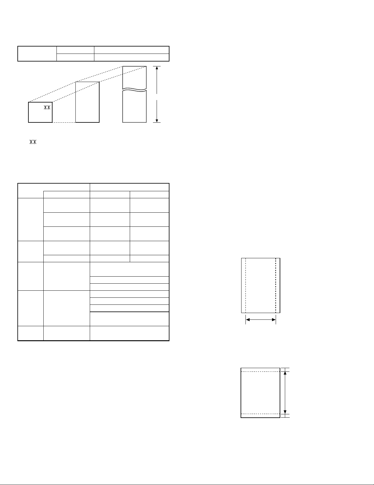
FO-6600U
Readable width
[3] Transmittable documents
1. Document Sizes
Normal size
(Min.)
148mm 216mm
Use document carrier sheet for smaller documents.
* With special sizes, only one sheet can be fed into the machine at a
time. Insert next page into feeder as current page is being scanned.
2. Paper Thickness & Weight
Weight Japanese indication 45kg paper 70kg paper
indication Size 4 × 6
Metric system 52g/m
indication
American indication 14 LB 20 LB
LB system indication
Thickness Metric system 0.06mm 0.1mm
indication indication
Inch system indication
Document Document size (148mm × 128mm) ~
size Range W letter (279.4mm × 432mm)
Number of Document size B6 ~ Letter/A4 size 50 sheets
ADF sheets
Paper Kind Paper of fine quality/bond paper/
quality Kent paper
Weight B4 size/Legal 20 sheets
3. Document Types
• Normal paper
Documents handwritten in pencil (No. 2 lead or softer), fountain pen,
ball point pen, or felt-tipped pen can be transmitted.
Documents of normal contrast duplicated by a copying machine can
also be transmitted.
• Diazo copy (blueprint)
Diazo copy documents of a normal contrast may be transmitted.
• Carbon copy
A carbon copy may be transmitted if its contrast is normal.
width 5.83"–8.5"(148 – 216 mm)
length 5.04" – 11"(128 – 279 mm)
(Max.)
(Max.)
Letter size
128mm
[Normal size]
Indication Lower Limit Upper Limit
279mm
216mm
[Special size]
Product specifications
2
0.0024" 0.0035"
A4 (210mm × 297mm)
Letter (216mm × 279mm)
W letter size 1 sheet
90 kg (104g/m2) or more
135 kg (157g/m2) or less1 sheet
80g/m
432mm
2
4. Cautions on Transmitting Documents
• Documents written in yellow, greenish yellow, or light blue ink cannot
be transmitted.
• Ink, glue, and correcting fluid on documents must be dry before the
documents can be transmitted.
• All clips, staples and pins must be removed from documents be-fore
transmission.
• Patched (taped) documents should be copied first on a copier and
then the copies used for transmission.
• All documents should be fanned before insertion into the feeder to
prevent possible double feeds.
5. Automatic Document Feeder Capacity
Number of pages that can be placed into the feeder at anytime is as
follows:
Normal size: max. 50 sheets (14 lbs – 20 lbs)
Special size: single sheet only (manual feed)
NOTES:
• When you need to send or copy more pages than the feeder
limit, place additional pages in feeder when last page in
feeder is being scanned.
• Place additional pages carefully and gently in feeder.
If force is used, double-feeding or a document jam may
result.
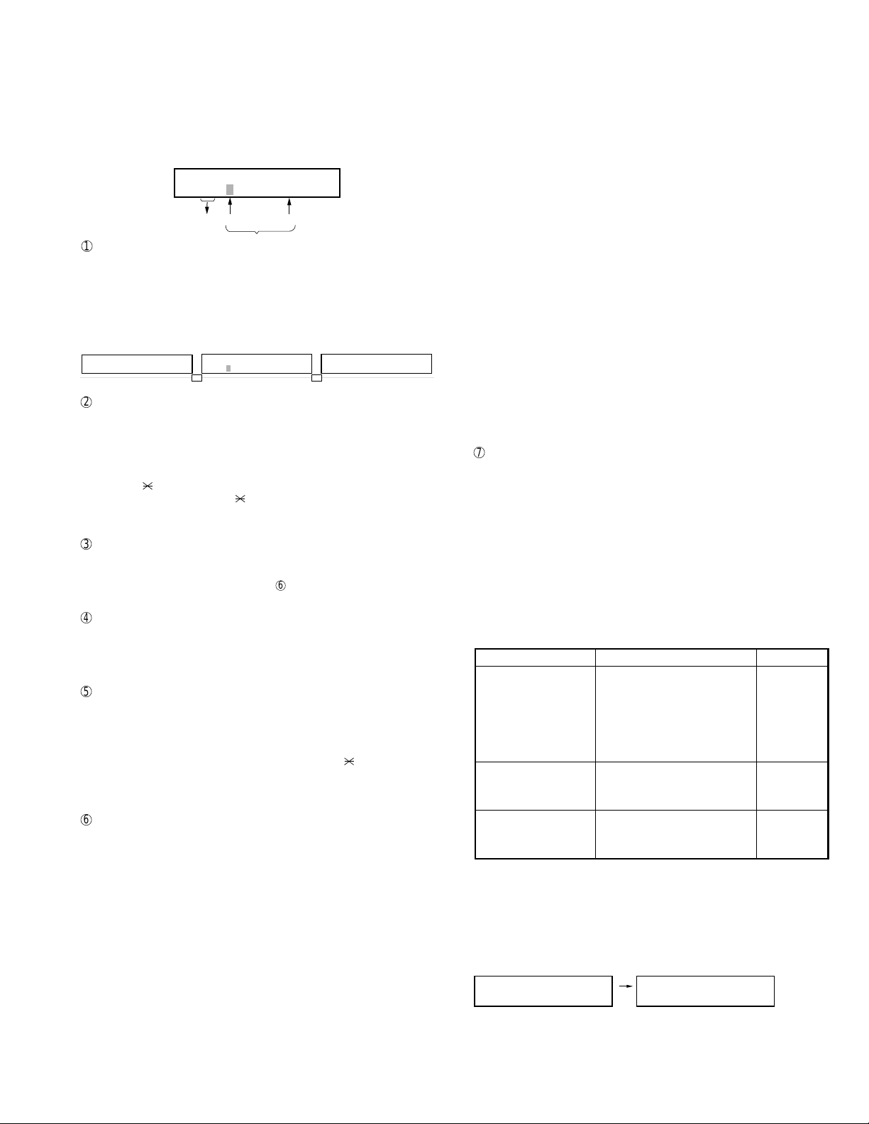
6. Readable Width & Length
The readable width and length of a document are slightly smaller than
the actual document size.
Note that characters or graphics outside the effective document scanning range will not be read.
• Readable width
8.3" (208 mm) max.
• Readable length
This is the length of the document sent minus 0.16" (4 mm) from the top
and bottom edges.
4mm
Readable length
4mm
1 – 4
Page 7
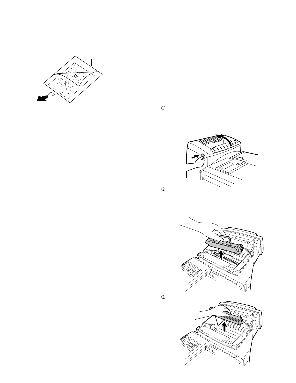
7. Use of Document Carrier Sheet
A document carrier sheet must be used for the following documents.
• Those with tears.
• Those smaller than size 5.83" (W) × 5.04" (L) (148 mm (W) × 128
mm (L)).
• Carbon-backed documents
Make print straight
across paper
E.G.
Place the document
carrier in the document
feeder with the clear film
side down
Direction of insertion
NOTE: To transmit a carbon-backed document, insert a white sheet of
paper between the carbon back of the document and the document carrier.
• Those containing an easily separable writing substance (e.g., trac-
ing paper written on with a soft, heavy lead pencil).
NOTES: • When using the document carrier, carefully read the in-
structions written on the back.
• If the document carrier is dirty, clean it with a soft, moist
cloth, and then dry it before using for transmission.
• Do not place more than one document in the carrier at a
time.
• The thickness of document which can be held with the carrier sheet
is up to 20 lb.
FO-6600U
TELEPHONE JACK
A standard RJ11C telephone jack must be located near the machine.
This is the telephone jack commonly used in most homes and offices.
• Plugging the fax machine into a jack which is not an RJ11C jack may
result in damage to the machine or your telephone system. If you do
not know what kind of jack you have, or need to have one installed,
contact the telephone company.
If the machine is moved from a cold to a warm place...
If the machine is moved from a cold to a warm place, it is possible that
the reading glass may fog up, preventing proper scanning of documents
for transmission. To remove the fog, turn on the power and wait approximately 2 hours before using the machine.
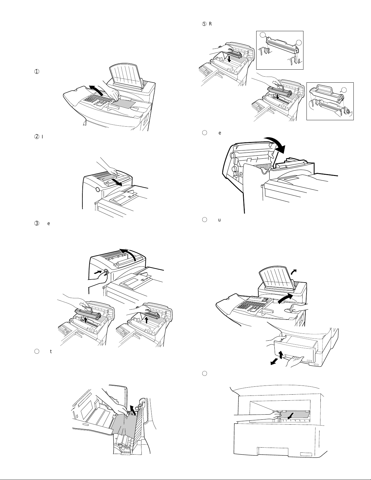
2. Installing the printer cartridges (Toner
cartridge: FO-45ND/Drum cartridge: FO-45DR)
1
Press the button on the side of the printer compartment, and open
the printer cover.
• Caution! The ribs on the bottom of the inside of the printer cover
become very hot during printing. Be careful not to touch them.
• If you are installing the cartridges for the first time, go to Step 4.
[4] Installation
1. Site selection
T ake the following points into consideration when selecting a site for this
model.
ENVIRONMENT
• The machine must be installed on a level surface.
• Keep the machine away from air conditioners, heaters, direct sun-
light, and dust.
• Provide easy access to the front, back, and sides of the machine. In
particular, keep the area in front of the machine clear, or the original
document may jam as it comes out after scanning.
• The temperature should be between 41° and 95°F (10° and 35°C).
• The humidity should be between 30% and 85% (without condensa-
tion).
ELECTRICITY
A 120 V, 60 Hz, grounded (3-prong) AC outlet is required.
Caution!
• Connection to a power source other than that specified will cause
damage to the equipment and is not covered under the warranty.
• If your area experiences a high incidence of lightning or power surges,
we recommend that you install a surge protector for the power and
telephone lines. Surge protectors can be purchased at most telephone
specialty stores
2
If you are replacing the cartridges, grasp the handle on the toner
cartridge, and pull the toner cartridge out of the compartment.
• If you are only replacing the drum cartridge, place the toner car-
tridge on a piece of paper on a horizontal surface.
• If you are only replacing the toner cartridge, go to Step 6.
3
Pull the old drum cartridge out of the compartment.
1 – 5
Page 8
FO-6600U
LIFE
V
2
START
LIFE
V
3
START
4
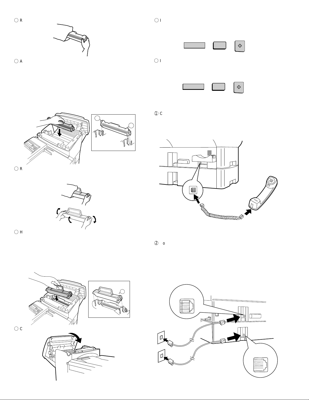
Remove the new drum cartridge from its packaging.
5
Align the arrowhead on the right side of the drum cartridge (the right
side is marked "R") with the arrowhead pointing down on the right
side of the compartment, and insert the cartridge into the compartment so that the ends of the cartridge move along the guides on the
sides of the compartment. Make sure the cartridge is set firmly in
place.
• Place the old drum cartridge (if you removed one) in the empty
drum cartridge bag, seal the bag, and dispose of it in a way that
conforms to any local regulations that may exist in your area.
• If you are not replacing the toner cartridge, go to Step 7.
L
Left
Right
R1
9
If you replace the toner cartridge, reset the toner counter by pressing
the LIFE key (flip up the Rapid Key overlay if necessary), the "2" key,
and the ST ART key.
F
If you replace the drum cartridge, reset the drum counter by pressing
the LIFE key (flip up the Rapid Key overlay if necessary), the "3" key,
and the STAR T key.
3. Assembly and connections
1
Connect the handset cord to the handset and the fax as shown.
• The ends of the handset cord are identical, so they will go into
either jack.
Place the handset on the handset rest.
6
Remove the new toner cartridge from its packaging, and shake it
several times as shown.
• This ensures that the toner is well distributed inside the cartridge.
7
Hold the handle of the toner cartridge so that the "2" marked on the
cartridge is to the right, and insert the cartridge into the com-partment
that the two knobs on each side of the cartridge move along the two
guides on each side of the compartment. Press the handle down so
that the cartridge sets into place.
• Place the old toner cartridge (if you removed one) in the empty
toner cartridge bag, seal the bag, and dispose of it in a way that
conforms to any local regulations that may exist in your area.
2
Left
Right
Use the handset to make ordinary
phone calls, or to transmit and
receive documents manually.
2
Connect the LINE 1 jack and the LINE 2 jack to the appropriate wall
jacks with the telephone line cords. The wall jacks should be standard (RJ11C) single-line wall jacks for separate lines.
• Note: V oice communications, manual fax transmission and manual
fax reception are only possible on Line 1.
• The fax machine will only ring when a call is received on Line 1 (it
will not ring when a call is received on Line 2).
TEL.
LINE
8
Close the printer cover.
LINE 1
LINE 2
1 – 6
TEL.
LINE
Page 9
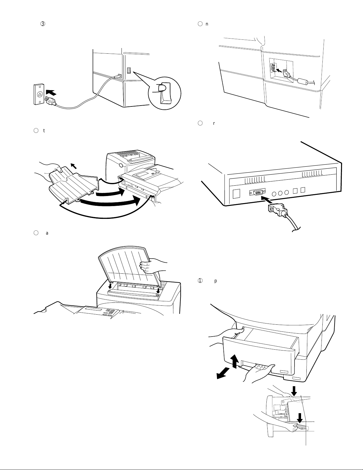
3
Plug the power cord into a 120V, 60Hz, grounded (3-prong) AC
outlet.
Press the power switch to turn on the power.
ON |
OFF 0
4
Attach the original document OUT tray by inserting the tabs into the
holes in the fax as shown.
FO-6600U
6
Insert the male end of the PC interface cable into the port on the right
side of fax as shown. Tighten the attached screws with a screwdriver .
7
Insert the female end of the PC interface cable into the serial (RS232C)
port on your computer. Tighten the attached screws with a screwdriver.
5
Attach the received document tray by inserting the tabs into the holes
in the fax as shown.
4. Loading printing paper
The paper cassettes and the paper tray hold the paper on which received documents are printed. The FO-6600 comes with two paper cassettes. Each paper cassette can hold 500 sheets of either legal or letter
size paper. The paper tray can hold 150 sheets of either legal or letter
size paper.
1
Grasp the hand hold on the cassette as shown, lift the cassette slightly,
and then pull it out as far as it will go. Do not force. Push down on
green levers on both sides of the cassette tray as shown, and then
pull it completely out of the fax using both hands.
1 – 7
Page 10
FO-6600U
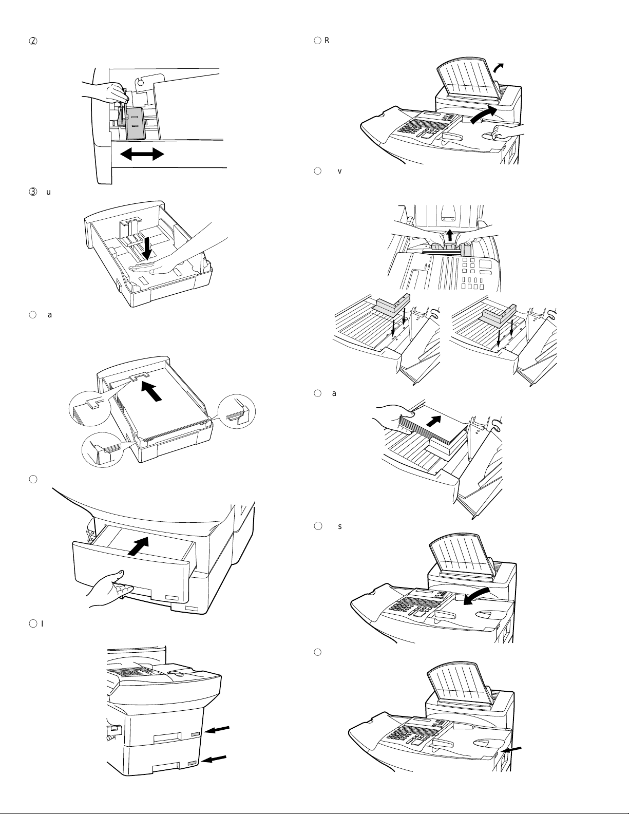
2
Pinch the ends of the paper guide together, and move the guide to
the appropriate position depending on whether you are loading letter
or legal size paper.
3
Push the pressure plate down until it locks into position.
7
Rotate the received document tray back. Grasp the hand hold on the
original document IN tray as shown, and open it.
8
Move the paper guide to the appropriate position depending on
whether you are loading letter or legal paper.
• T o remove the paper guide, press its inner side at the arrow marks
and lift.
4
Place a stack of paper in the cassette, print side up. Make sure the
two far corners of the paper go under the paper holders as shown.
• Make sure the stack of paper is not higher than the tabs at the top
of the paper guide. If it is, remove some of the paper.
5
Put the cassette back in the fax.
LTR
Letter
9
Place the paper in the tray.
F
Close the original document IN tray .
LGL
Legal
6
If desired, attach a letter or legal sticker as appropriate to the cas-
sette.
1 – 8
G
If desired, attach a letter or legal sticker as appropriate to the fax as
shown.
Page 11
5. Clearing paper jams
If a document doesn’t feed through the scanner properly during transmission or copying, or DOCUMENT JAM appears in the display , first try
pressing the ST ART key . If the document doesn’t come out of the feeder,
open the operation panel by squeezing the operation panel release on
the right side of the operation panel (marked "PULL OPEN"), and gently
pull out document.
1
2
If the leading edge of the document is protruding from the printer
compartment outlet, try pulling it out.
• If you are unable to clear the paper jam in this way , continue with
the following steps.
5
Replace the drum cartridge, and then the toner cartridge.
L
R1
Left
Right
Left
6
Close the printer cover.
FO-6600U
2
Right
3
Open the printer cover and remove the toner cartridge and drum
cartridge.
• Caution! The ribs on the bottom of the inside of the printer cover
become very hot during printing. Be careful not to touch them.
4
Gently pull the paper out of the compartment.
• If the leading edge of the paper has entered the fusing unit, first
pull the leading edge out of the fusing unit, then pull the paper out
of the compartment.
• Be sure to remove any torn pieced of paper.
7
If you didn’t find any paper in the printer compartment, or if PAPER
JAM still appears in the display after you close the printer cover, check
each paper cassette and the paper tray.
• To release the cassette when pulling it out, press down on the
levers on each side of the cassette.
• To check the paper tray, grasp the hand hold on the original docu-
ment IN tray and rotate the tray up.
8
Gently pull out any jammed paper you find, and then replace the
cassette or close the original document IN tray.
1 – 9
Page 12
FO-6600U
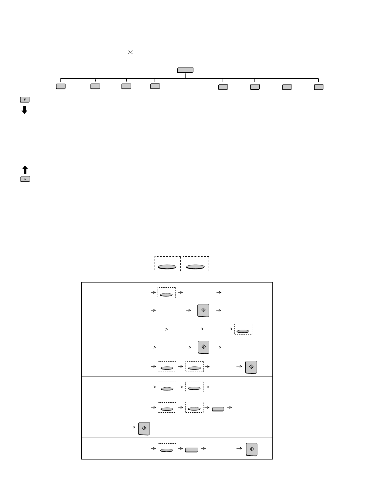
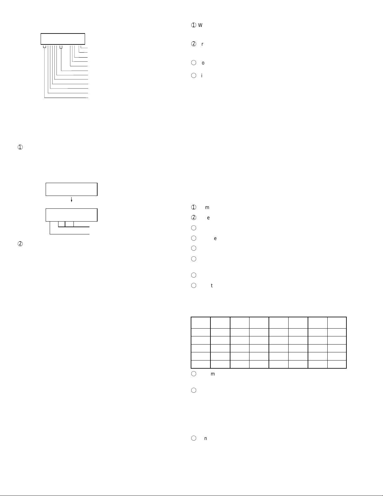
[5] Quick reference guide
FUNCTION key menu
The following chart shows the layout of the functions and settings accessed by pressing the FUNCTION key. First press the FUNCTION key, the
appropriate numeric key as shown, and then "#" or "
to the detailed instructions on the page shown below the setting.
" until the desired item appears. Instructions for making each setting appear in the display. Refer
FUNCTION
1
Reception
Mode
2
Listing Mode
Activity Report
Timer List
Telephone
Number List
Relay Group List
Passcode List
Option Setting
List
Program/Group
List
Batch
Transmission List
Department
Usage List
Confidential
Reception List
Anti Junk Fax
Number List
3
Entry Mode
Fax/Tel
Numbers for
Auto Dialing
Passcode Number
Own Number and
Name Set
Date and Time
Set
Day Light Saving
ID Number
System Number
Store Junk Fax
Number
Department
Code Mode
Optional Settings
Fine Resolution
Priority
Number of Rings in
Auto Answer Mode
Number of Rings to
Auto Manual Answer
Auto Listing
Transaction Report
Print Select
Recall Times
Recall Wait Interval
Security Selection
ECM
Auto cover Sheet
Memory Scanning
Copy Reduce
Copy Cut-off
Receive Reduce
Image Memory
Print
Cassette Selection
Cassette
Changeover
Note: Steps which are optional are enclosed in a dotted frame:
4
RESOLUTION
Retransmission
Times
Retransmission
Interval
Heater Mode
Junk Fax Check
Alarm Buzzer
Dial Mode
Quick on Line
Multi TTI
Beep Length
Tel. Billing Code
Department Code
Mode
Distinctive Ringing
Verification Stamp
Print Hold
PC-Interface Mode
Receive Unit
Dial Selection
Separate Mode
LINE
6
Print Hold
Mode
Hold Data Print
Print Hold Code
Set
Print Hold Code
Clear
7
Program/Group
Mode
Program Entry
Mode
Group Entry
Mode
8
Serial Polling
Mode
9
Memory Polling
Mode
Memory Polling Set
Memory Polling
Clear
Transmitting documents
Normal Dialing (1)
Normal Dialing (2)
Direct Keypad
Dialing
Rapid Key Dialing
Speed Dialing
Redialing
Load
document
Lift handset
or
press SPEAKER
Load
document
Load
document
Load
document
START
Load
document
RESOLUTION
Wait for
reception tone
Dial (press
numeric keys)
Wait for
reception tone
RESOLUTION
RESOLUTION
RESOLUTION
RESOLUTION
Lift handset
or
press SPEAKER
START
Load
document
START
LINE
LINE
LINE
REDIAL
Dial (press
numeric keys)
Hang up
Hang up
Dial (press
numeric keys)
Press Rapid
key
SPEED DIAL
Wait for
reception tone
RESOLUTION
START
Enter Speed Dial number
(press numeric keys, -if less
than 3 digits, press START
to complete entry)
START
1 – 10
Page 13
FO-6600U
CHAPTER 2. ADJUSTMENTS
[1] Adjustments
General
Since the following adjustments and settings are provided for this model,
make adjustments and/or setup as necessary.
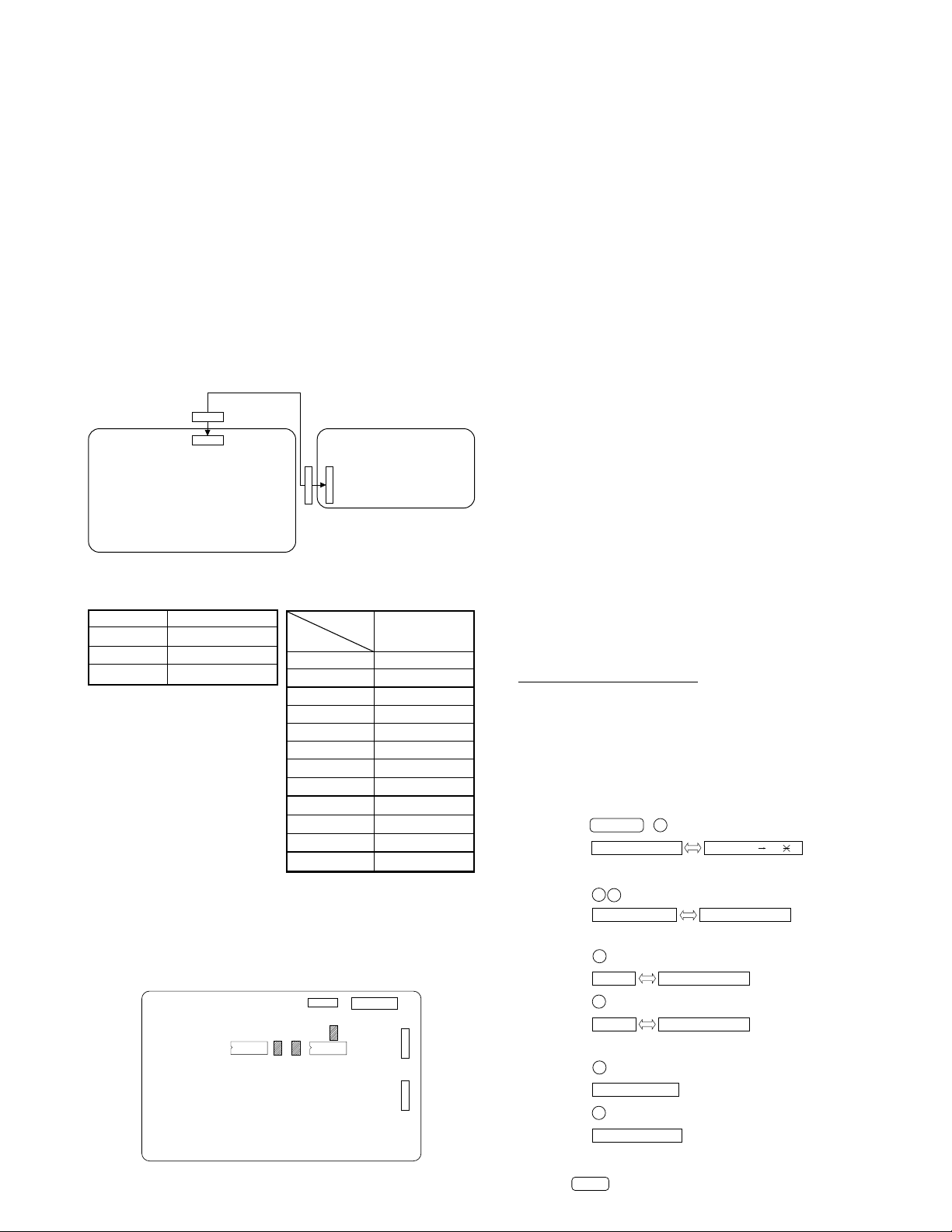
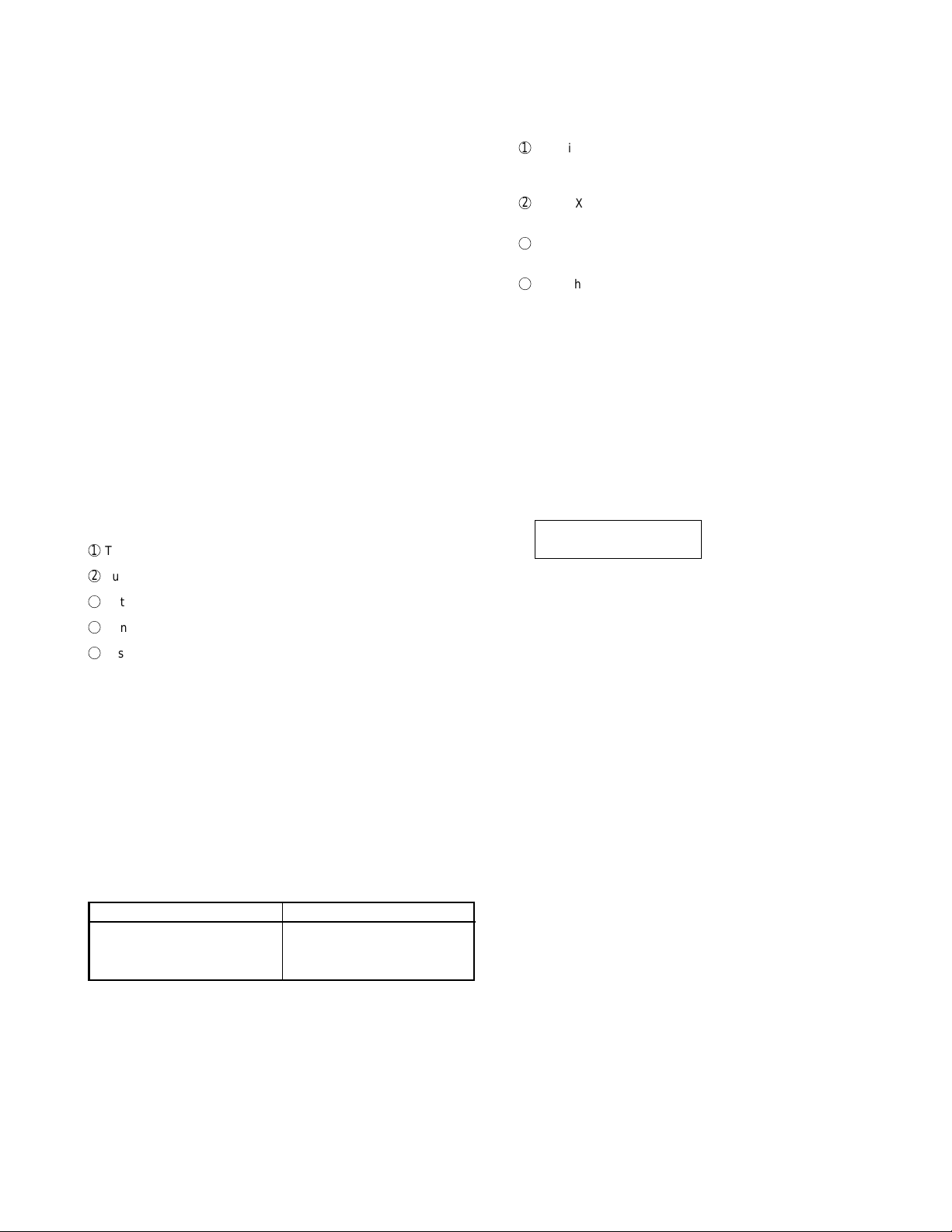
1. Adjustments
Adjustments of output voltage (FACTORY ONLY)
1. Install the power supply unit in the machine.
2. Set the recording paper and document.
3. When the document is loaded, power is supplied to the output lines.
Confirm that outputs are within the limits below.
Output voltage settings
CNPW
CONTROL
PWB
CNPW
Fig. 1
Output Voltage limits
+5V 4.75V~5.25V
+12V 11.5V~12.5V
VM (+24V) 23.04V~24.96V
Connector
Pin No.
1VM
2VM
3VM
4MG
5MG
6MG
7 +5V
8 +5V
9DG
10 DG
11 +12V
12 AG
2. IC protectors replacement
ICPs (IC Protectors) are installed to protect the TX motor drive circuit
and verification stamp drive circuit. ICPs protect various ICs and electronic circuits from an overcurrent condition.
The location of ICPs are shown below:
CONTROL
PWB
(TOP SIDE)
IC20
F101
Fig. 2
F102
CNPW
IC21
POWER SUPPLY
PWB
No. CNPW
CNPRT
F103
CNRS
CNPN
(1) F102 (CCP2E20) is installed in order to protect IC’s from and
overcurrent generated in the verification stamp drive circuit. If F102
is open, replace it with a new one.
(2) F101, F103 (CCP2E30) is installed in order to protect IC’s from an
overcurrent generated in the TX motor drive circuit. If F101, F103 is
open, replace it with a new one.
In addition to the replacement of F101, F103 and F102, the factor
causing F101, F103 and F102 to open must also be repaired. If not,
F101, F103 and F102 will open again.
Replacement parts
CCP2E20 (Sharp code: VHVCCP2E20/-1)
CCP2E30 (Sharp code: VHVCCP2E30/-1)
3. Volume adjustment
Y ou can adjust the volume of the speaker , handset, and ringer using the
UP and DOWN keys on the operation panel (flip up the Rapid Key overlay to access the keys).
Speaker
The speaker has 3 volume levels: HIGH, MIDDLE, and LOW. To adjust
the volume of the speaker, press the SPEAKER key and then press the
UP or DOWN key until the desired level appears in the display. Press
the SPEAKER key again to turn the speaker off.
Handset
The handset receiver has 3 volume levels: HIGH, MIDDLE, and LOW.
To adjust the volume of the handset receiver, lift the handset and then
press the UP or DOWN key until the desired level appears in the display .
Ringer
The ringer has 4 volume levels: HIGH, MIDDLE, LOW, and OFF. To
adjust the volume of the ringer, press the UP or DOWN key until the
desired level appears in the display (make sure the SPEAKER has not
been pressed and the handset is not lifted). The fax will ring at the new
volume level each time you change the level. If you select OFF, press
the START key to confirm your selection.
4. Settings
(1) Dial mode selector
OPTION SETTING: DIAL MODE (Soft Switch No. SW2 DATA No. 1)
Use this to set the fax machine to the type of telephone line you are on.
• The factory setting is "TONE".
OPTIONAL SETTING: DIAL MODE
Soft Switch No. SW2 DATA No.1 for Line 1
Use this to set the fax machine to the type of
telephone line you are on.
• The factory setting is "TONE".
(step 1) Select "OPTION SETTING".
(step 2) Select "DIAL MODE".
(step 3) Select "LINE", using "1" or "2".
(step 4) Select, using "1" or "2".
(step 5) End, using the "STOP" key.
2 – 1
No. SW15 DATA No.1 for Line 2
KEY:
DISPLAY:
KEY:
DISPLAY:
KEY:
DISPLAY: 1:LINE 1
KEY:
DISPLAY:
KEY:
DISPLAY: TONE SELECTED
KEY:
DISPLAY:
KEY:
FUNCTION 4
4:OPTION SETTING ENTER #01 33, ,#
3
2
23:DIAL MODE
1
2
2:LINE 2
1
2
PULSE SELECTED
STOP
1=LINE 1,2=LINE 2
1=TONE, 2=PULSE
1=TONE, 2=PULSE
Page 14
FO-6600U
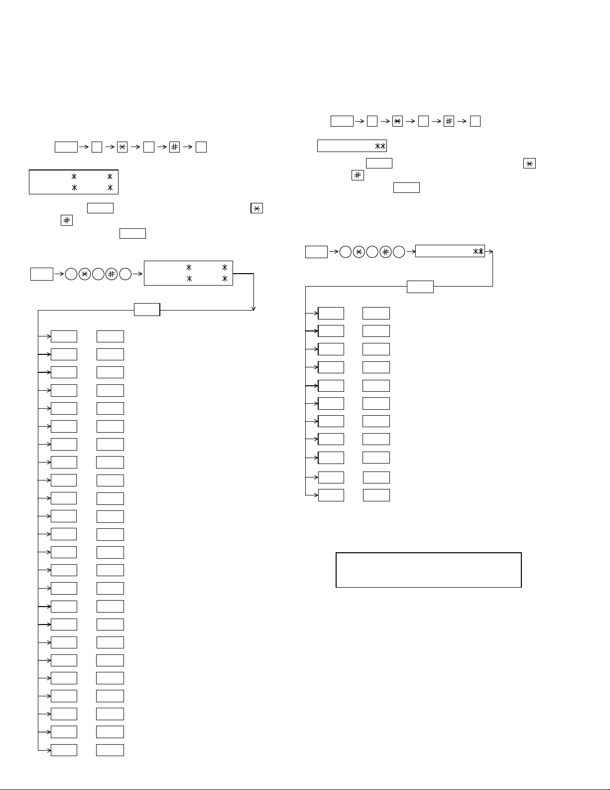
[2] Diagnostics and service soft switch
1. Operating procedure
Two kinds of diagnoses are supported.
1-1. Fax diagnosis
This diagnosis is concerned with the main body of fax which is used
for production and service support.
Entering the diagnostic mode
FUNC
Press
display will appear.
MAIN:
FBQ0 FBQ1
SUB:
FBR0 FBR0
Then press the
and the key or select with the rapid key.
Enter the mode with the
(Diag
•
specifications)
FUNC
02 PRINT AREA
03 ROM & RAM CHECK
04 AUTO FEEDER MODE
05 AGING MODE
06 PANEL CHECK MODE
07 OPTICAL ADJUST MODE
08 PRODUCT CHECK
09
10
9 8
START
key. Select the desired item with the
START
key.
9 8 7
START01 SOFT SWITCH MODE
START
START
START
START
START
START
START
START
START
MAIN:
SUB:
START
SIGNAL SEND MODE
COMM. CHECK MODE
7
, and
FBQ0 FBQ1
FBR0 FBR0
the
following
key
1-2. Print diagnosis
This diagnosis is concerned with the print which is used for production and service support.
Entering the diagnostic mode
FUNC
Press
display will appear.
PCU ROM Ver.:
Then press the
key and the key or selectwith therapid key.
Enterthe modewith the key.
(Diag•specifications)
FUNC
01
02
03
08
09
9 8
START
9 8 6
START
START
START
START04
START05
START06
START07
START
START
START10
START11
6
, and
the
key. Select the desired item with the
START
PCU ROM Ver.:
START
AREA PRINT MODE
CHECK PATTERN 1
CHECK PATTERN 2
CHECK PATTERN 3
PAPER FEED AGING
BIAS ADJUST MODE
LIFE SET MODE
LIFE ALL CLEAR
LIFE ENTRY MODE
TOP ADJUST MODE
LIFE CLEAR MODE
following
11
12
13
14 RS232C CHECK MODE
15
16 CONF. PASSCODE
17 PRINT HOLD CODE
18 MEMORY SET MODE
19 MOTOR AGING
20 STAMP AGING
21 SCANNER SET MODE
22 DIAL TEST MODE
23 COPY DIAG MODE
START
START
START
START
START
START
START
START
START
START
START
START
START
START24 SIGNAL SEND MODE 2
MEMORY CLEAR
FLASH MEMORY
ALL FAX/TEL ENTRY MODE
DEPT. PASSCODE
3) Memory clear when power is turned on
Pressing the START and STOP keys, turn on the main power, and the
following message will be displayed.
MEMORY CLEAR
EXECUTE ? 1 = YES , 2 = NO
Here, when 1: YES is selected, the memory will be cleared to be ready
for operation.
If 2: NO is selected, it will continue ready for operation as it is.
2 – 2
Page 15
FO-6600U
2. Diagnostic items description
2-1. Fax diagnosis
1) Soft switch mode
In this mode, the soft switch are set and the soft switch list is printed.
Soft switch mode screen
1
Switch number selection
Soft switch mode screen
S O F T S W I T C H M O D E
S W 0 1 = 0 0 0 0 0 0 0 0
Switch
No.
1
8
Data
• Press START key for setting of the next soft switch. If the soft
switch number is the final, pressing START key will exit the soft
switch mode.
• Enter two digits of a soft switch number to set the switch number.
If a switch number of unexisting soft switch is entered, key error
buzzer sounds to reject the input.
S O F T S W I T C H M O D E
S W 0 1 = 0 0 0 0 0 0 0 0
2
Data number selection
S O F T S W I T C H M O D E
S W 1
1 6
S O F T S W I T C H M O D E
S W 1 6 = 0 0 0 1 0 1 1 0
The cursor position shows the data to be set.
Pressing # key moves the cursor to the right. If, however, the cursor is
on data number 8, pressing # key shifts the cursor to data number 1
of the next switch number. If the switch number is the final, pressing
# key will exit the soft switch mode.
Pressing
key moves the cursor to the left. If, however, the cursor is
on data number 1, pressing key shifts the cursor to data number 1
of the former switch number. If the switch number is 1, pressing key
will not move the cursor.
3
Data setting method
Press the FUNCTION key, and the data at the position of the cursor
will be reversed to 0 when it is 1, or to 1 when it is 0. (If the soft switch
can be changed at the bit (Refer to 6.), the error buzzer will sound
with the process not received.)
4
Outputting method of soft switch list
In the soft switch mode, press the REPORT key, and the soft switch
list will be output.
If the recording paper runs out or is clogged, the key error buzzer will
sound with the process not received.
5
Storage of data
In the following case, the data of the soft switches set will be stored.
• It is shifted to set the next soft switch by pressing the START
switch.
• It is shifted to set the next soft switch with the [#] key.
• It is shifted to set the last soft switch with the [ ] key.
• It is shifted to set another soft switch by inputting two digits as the
switch number. (When 2 digits are completely input.)
• Output of the soft switch list is started.
6
Inhibition of data change
(This is also applicable for the optional setting.)
In the following case, it is inhibited to change the data with the key
error buzzer.
• When the print hold bus code is not registered, the print hold
func-tion is turned from OFF to ON.
• When the print hold function is on, the print hold bus code is
cleared.
• When the memory is used because of substitutive receiving, etc,
the print hold function is mutually turned on/off.
• OFF to ON of telephone billing function which is using the image
memory is used (Note: In the existing set, the telephone billing
code function is specified from OFF to ON when the timer system
com-munication (including the batch communication) is set.)
Here, the memory is usable when the telephone billing code function is on. It can be set from ON to OFF while the memory is
used. However, if setting is practically changed even once, it can
not be returned from OFF to ON.
• Mutual switch of ON/OFF of PC interface function during opera-
tion of image memory.
• When the PC interface board is not mounted, [Switch of OFF →
ON of the item of "PC interface function" and of FAX → PC of the
item of "automatic receiving in the PC interface mode]
(Note: This supports not only the operation protect of the op-tional
setting and soft switch mode but also an example of the automatic compensation of soft switch to OFF/FAX when the power is
turned on even if the PC PWB is removed when the optional setting and soft switch mode are set at ON/PC.)
(Though they are not provided, the existing model can operate
without setting of the soft switch when it is not installed.)
• OFF to ON of multi TTI function and telephone billing code func-
tion when the department control function is OFF.
• OFF to ON of department control function during use of image
memory.
(Note: In the existing set, the department control function is set
from OFF to ON when the timer communication (including the
batch sending) or the memory hold is set.)
• ON to OFF of continuous serial polling function when the continu-
ous serial polling is started.
(Note: In the existing set, "ON to OFF of the continuous serial
polling function when the continuous serial polling is registered"
has been applied, but the conditions are now moderated. However, reg-istration is impossible to the program of the new continuous serial polling when the continuous serial polling function
is OFF.)
• In addition, change of all soft switches during communication
7
Linked change of data (This is the same even in the optional setting.)
• When the department control function is off, the multi TTI function
and telephone billing code function are turned off.
2) Print area
According to the size of the specified sheet, the effective printing area is
printed.
3) ROM & RAM check
The sum value of ROM, the work and the back-up RAM are checked.
The RS232C interface is also checked. If any error occurs, the buzzer
will inform it. (Refer to the following table). Finally, the result will be printed.
This diagnosis does not check the flash memory. The flash memory is
checked with the flash memory test.
Number of buzzer sounds Device checked Remarks
1 time <Short sound> ROM1 Main
2 times <Short sounds> ROM2 Main
3 times <Short sounds> Integrated ROM/RAM Main
4 times <Short sounds> D-RAM Main
5 times <Short sounds> S-RAM Main
*6 times <Short sounds> S-RAM (on the optional memory) Main
1 time <Long sound> ROM Sub 1
2 times <Long sounds> Integrated ROM/RAM Sub 1
3 times <Long sounds> D-RAM Sub 1
4 times <Long sounds> ROM Sub 2
5 times <Long sounds> Integrated ROM/RAM Sub 2
6 times <Long sounds> D-RAM Sub 2
* As practical, it is judged that the optional memory is not installed if
any error occurs. Therefore, it does sometimes not sound.
For the short and long sounds, one pattern is as follows.
Main system: 0.25 seconds ON/0.25 seconds OFF
Sub system: 1.00 second ON/0.25 seconds OFF
The execution state of checking is as follows. Moreover, the list of the
check result is output after checking is ended.
Display during check
ROM CPU SRAM DRM DPR
• • • • • • • • • • • • • •
Display after check
ROM CPU SRAM DRM DPR
PPPPPPP E PPP PP
P=PASS E=ERROR
ROM/RAM
check list
output
2 – 3
Page 16
FO-6600U
<Relationship between display and memory>
Display during check
ROM CPU SRAM DRM DPR
• • • • • • • • • • • • • •
Dual Port Ram for Comm. PWB
Dual Port Ram for Comm. PWB
DRAM(2Mbit) for Comm. PWB - SUB2
DRAM(2Mbit) for Comm. PWB - SUB1
DRAM(2Mbit) for Comm. PWB - MAIN
SRAM(512kbit x 2)
CPU - SUB2
CPU - SUB1
CPU - MAIN
EPROM(16bit bus / 4Mbit) - SUB2
EPROM(16bit bus / 4Mbit) - SUB1
EPROM(8bit bus / 4Mbit x 2) - MAIN
The check result of RS232C interface board is listed and printed together with the check result of ROM&RAM.
4) Auto feeder mode
The auto feed function can be checked by inserting and discharging the
document. (The distance between pages can be displayed during operation of the scanner.)
1
Check of auto feed function
After this mode is activated, set up the document, and press the
ST ART key , and it will be automatically fed. (Before the ST ART key is
pressed, the document sensor alone is activated.) Moreover, the
document size (A4/B4) and sensor information (A4/B4/ORG) are displayed when the document sensor is turned.
04 : AUTO FEEDER MODE
()
After setup of the document
04 : AUTO FEEDER MODE
B4 (A4 B4 ORG)
Only the sensor which is
activated (fallen down) is displayed.)
The paper sheet size (A4/B4) is
displayed.
2
Display of distance between pages during operation of the scanner
• Soon after this mode is c\activated, press the FUNCTION key for
5 seconds or more, and the display mode of the distance between pages will be activated. Then, set up the sending paper
and select the image quality, and then press the START key, and
operation will be started.
Be sure to press the FUNCTION key prior to the START key. If
the FUNCTION key is not pressed but the STAR T key is pressed,
it will operate in the same manner as in the existing auto feeder
mode.
If the START key is pressed, the FUNCTION key will be invalid
hereafter. Therefore, the display mode of the distance between
pages and the existing mode can not be changed.
• While the sending paper is read, the image quality key can be
input. STD/FINE/S-FINE modes are usable. However, the same
operation of FINE will be selected if the intermediate tone is set.
• The image quality, the length of the sending page read, the page
distance to the next sending paper and the total of the sending
papers read are shown on the display.
• When the stop key is pressed or 100 sending papers are read,
the content shown on the display will be totally output as the list
after the remaining sending papers are discharged.
5) Aging mode
If any document is set up in the first state (when started), copying will be
executed. If it is not set up, "check pattern 1" of the print diagnosis is
output at the intervals of 1 time/60 minutes. (A total of 10 sheets are
output.)
6) Panel check mode
This is used to check whether each key is normally operated or not.
According to the key input, LCD is displayed. Moreover, during exe-cution,
the document reading lamp is turned on.
1
When [P ANEL CHECK MODE] is displayed, press the [START] key.
The test will be started. When the test is started, LED’s will sequentially come on. It is used to check all LED’s.
2
Press any other key except [STOP] key .
At this time, the name of each key will be displayed every push of the
key.
3
However, if any key is pressed with the page plate opened, it will be
equal to a press of key 32 with the page plate opened.
4
Finally press the [STOP] key .
If all keys can be input, the key input "ALL KEY OK!!" will be displayed when the STOP key is ended.
The screen will be all displayed in black, and the test result will be
printed.
In this test, it is okayed if all the other keys except [STOP] key have been
pressed from start of the test to its end (the [STOP] key is pressed). If
any key is skipped, it will be regarded as "KEY ERROR!!", and the name
of the key not pressed will be printed on the list as the result. This will
complete printing.
• If the ten-key pad is used to input in this mode, DTMF corresponding
to the pressed key is sent out continuously (lines 1/2 simultaneously).
7) Optical adjust mode
The document reading LED is turned on.
8) Product check
The diagnosis is used in the production process.
After shift to the mode, the following operations are sequentially executed. At this time, the sensor of read-error can be checked by feed-ing
the B3 document. Set up one short document of B4 size.
1
Memory clear (Same as Diagnosis 11)
2
Panel test (Same as Diagnosis 06)
3
Dial test (Same as Diagnosis 24)
4
Document feed
5
Stamp press
6
ROM & RAM test, RS232C interface board check (Same as the Di-
agnosis 03)
7
Flash memory test mode (Same as Diagnosis 12)
8
Registration of fixed data
Registration of rapid key No. and other data necessary for produc-
tion.
The registered data are shown in the following table. The chain dial is
not set for any destination.
Rapid FAX Rapid FAX Rapid FAX Rapid FAX
No. No. No. No. No. No. No. No.
01 20 06 25 11 1 21 01
02 21 07 26 12 2 22 02
03 22 08 27 13 3 23 03
04 23 09 28 14 4 24 04
05 24 10 29 15 5 25 05
9
Transmission check (Same as Diagnosis 10)
The soft switches necessary for production are set.
F
Test result print (two sheets)
• AUTO FEEDER CHECK LIST
• FLASH MEMORY CHECK LIST
Memory clear printing
Panel test result printing
ROM&RAM test result printing
Check result printing of RS232C interface board
G
Print area printing (one sheet)
2 – 4
Page 17
FO-6600U
9) Signal send mode
After shift to the mode, press the START key, and the signals will be
transmitted in the following sequence.
It can be used to check the modem and so on.
• The selection signal is sent out simultaneously from the lines 1/2 in
this mode.
[ 1] No signals
[ 2] 4800BPS (V27ter)
[ 3] 14400BPS (V . 33)
[ 4] 12000BPS (V . 33)
[ 5] 14400BPS (V . 17)
[ 6] 12000BPS (V . 17)
[ 7] 9600BPS (V . 17)
[ 8] 7200BPS (V . 17)
[ 9] 9600BPS (V . 29)
[10] 7200BPS (V . 29)
[11] 4800BPS (V27ter)
[12] 2400BPS (V27ter)
[13] 300BPS (FLAG)
[14] 2100Hz (CED)
[15] 1100Hz (CNG)
13) All FAX/TEL. entry mode
The function is used to simplify the registration of FAX/TEL No. during
aging.
First, write the reference destination No. with the Rapid No. 01 key in
the FAX No. registration mode before start of the diagnosis.
1
The diagnosis mode is activated. If anything is not registered in the
Rapid No. 01 or any program or group is not registered, it will pass
the diagnosis without doing anything.
2
The FAX/TEL No. (including the substitutive destination) of the Rapid
No. 01 is copied to the Rapid Nos. 02 thru 48.
3
FAX No. of the Rapid No. 01 is copied to SPEED key Nos. 001 thru
200.
4
If any chain dial is not in the Rapid No., the Rapid Nos. 02 thru 48 and
SPEED key Nos. 001 thru 200 are registered in the group No. 01.
If any chain dial is not set, the group will be not produced but the
chain dial setting alone of the Rapid No. 01 will be reset.
(In all others except the Rapid No. 01, the chain dials will be continu-
ously set as they are.)
(16th and subsequential letters of the destination name registered in the
Rapid No. 01 will be discarded.)
14) RS232C check mode
RS232C interface board is checked.
When the interface board is installed, the result will be printed after the
check.
It is not installed, the following will be displayed.
10) Comm. check mode
1
Turn on the line monitor.
2
Turn off the cover sheet function.
3
Set 0 km at the line equivalence.
4
Bring the copy mode into the continuity mode.
5
It is set to shift into the diagnosis mode when the SPEED key alone
is pressed.
After the check, it is necessary to be sure to return the aforemen-tioned
soft switches into the initial state.
(Clear the memory with the diagnosis.)
11) Memory clear
Clear the back-up memory to initialize the soft switches.
The flash memory will be initialized. Then, the initialized list be output.
12) Flash memory
The flash memory is checked.
The ordinary memories (ROM, SRAM, DRAM) are checked in the
ROM&RAM check process. The write/read test is taken every block to
print the result.
When an error occurs, the following error buzzer will sound.
Number of buzzer sounds Check device
7 times <Short sounds> Page memory
8 times <Short sounds> Flash memory
9 times <Short sounds> Flash memory (optional)
During operation of this diagnosis, dual operation is not possible at all.
If this is excessively repeated, it will shorten the life of the flash memory.
14: RS232C CHECK MODE
I/F PWB NOT CONNECT
The process will be ended after sounding of the error end buzzer.
15) Dept. passcode
The department passcode list is printed.
16) Conf. passcode
The confidential passcode list is printed.
Differing from printing of one box alone soon after registration, the confidential passcodes of all boxes are printed.
17) Print hold code
The print lockout passcode No. is printed.
2 – 5
Page 18

FO-6600U
18) Memory set mode
The set and dump list of the memory content is output.
• The address (8 digits (P) generally including the bank information is
input, and the data of 2 digits is continuously input.
Inputting is done in the hexadecimal mode. The ten-key is used for 0
thru 9, and the alphabetic keys A (RAPID01 thru 06) are used for A
thru F.
• During data inputting, the address can be moved forward and back-
ward one byte by one byte with "
address 0 is looped as the maximum address.)
" and "#". (The address prior to the
• The V alidity of the address is not checked. Accordingly , writ-ing/ read-
ing operations are possible in the address of the memory not assigned, the address of ROM and so on.
(However, as practical, writing is not done, and the data content runs
short each reading.)
Though writing is possible in the flash memory, a little time is re-
quired.
It is also necessary to take care that the life of the flash memory is
excessively shortened if much data is written in the flash memory.
Since it may run away depending the written content, take minute
care for the writing address.
• When the REPORT key is input, the memory dump list is produced
from the displayed address (here, it is limited at the 16-byte boundary address (address with end 0) which does not exceed the specified address and is just in front.). The dump list is output to a maximum of 99 pages. If any data of one page can be repeatedly developed and printed, the list is sufficient. But it is not desired that the
content of plural pages are developed in the memory once and are
then printed. If the STOP key is pressed, it will pass to the diagnosis
after the page which is now being printed is completed printed.
If the address exceeds the maximum address, it will return to the
address 0 and printing will be continued.
19) Motor aging
• Whether a document is present or not, the motor in the sending sys-
tem is kept in rotation until the STOP key is pressed.
• The image quality selection key can be input during stop alone to set
the rotation speed for the image quality .
(Here, the speed for FINE is selected when the intermediate tone is
specified.)
• The image quality for default at the start of execution is STD regard-
less of the image quality selection priority of the main body.
• For rotation, the key "1" selects the 1-2 phase excitation, "2" se-
lects the 2-phase excitation and "3" selects the micro step. It can not
be changed during rotation. The 1-2 phase excitation is set as default.
20) Stamp aging
• It is impossible if any document is not set up.
• The document is fed at the 10 mm intervals, and is continuously
stamped.
• The total number of stamps from entry of the mode is displayed on
the screen.
• The ordinary operation aging which stamps a finish every docu-ment
is executed in the ordinary copying mode.
21) Scanner set mode
• The reading width and motor drive conditions are set.
<Reading width>
1. Top margin
2. Bottom margin
3. Left adjustment (The left position alone is specified.)
Specify the above values.
• Select the above items 1, 2 and 3 with the [ ] and [#] keys, and set
the values with the [←] and [→] keys. The values can be set in the
range of +3.0 mm to -3.0 mm at the 0.1 mm intervals. While the [←]
and [→] key is continuously pressed one second or more, the setting
value is automatically increased/decreased (in the range between
the upper and lower limits).
• Input the quality selection key, and the value will be respectively set
corresponding to the selected image quality. Here, the interme-diate
tone is the same as for the setting value of FINE.
• ±0.0 mm is default for all.
<Drive conditions of motor>
4. Motor
5. Phase
6. Slow-up
7. Slow-down
Specify the above values.
• Select the above items 4 thru 7 with the [ ] and [#] keys, and select
the setting value with the ten-key.
Setting values
4. 6 steps
5. Selection of one mode from 1-2 phase, 2-phase and micro step
6. 3 steps
7. 3 steps
• Input the quality selection key, and the value will be respectively set
corresponding to the selected image quality. Here, the interme-diate
tone is the same as for the setting value of FINE.
1. TOP
2. BOTTOM
3. LEFT
4. MOTOR
5. PHASE
6. SLOW UP
7. SLOW DOWN
22) Dial test mode
The mode is used to inspect whether dialing is accurate in two kinds of
dial modes . All data which can be dialed in this mode are automatically called up in both PB mode and DP mode.
When this mode is activated, the following operations will be automatically executed . Whether the dialed content is right or not is judged with
the external instrument which is connected to the line cable.
1
After shift to the FAX diagnosis mode, press RAPID 24.
(Also switch the display with the [ ] and [#] keys.)
2
Press the START key.
3
Turn on CML, and dial the following in the PB mode.
1, 2, 3, 4, 5, 6, 7, 8, 9, , 0, #
4
Turn off CML 500 mS alone.
5
Dial the following in the DP mode.
1, 5, 9, 0
6
After dialing, turn off CML.
This mode uses the ordinary auto dial. (Accordingly, the signal send-ing
time and minimum pause are all the same as ordinary.
The measurement result in this mode is completely all the same as in
the ordinary dial mode.
Moreover, the same process as above is also done in the dial test mode
which is executed in the product check mode.
• The lines 1/2 operate simultaneously in this mode.
2 – 6
Page 19
FO-6600U
23) Copy diag mode
In order to shorten the process time during production, this mode is
used to automatically switch the copy mode. Three menus are pro-vided.
1. 1Set up two documents. (In case of two documents or more,
there is no problem.
2
Press the START key.
3
Copy 1st document in the fine mode/density AUTO. (One sheet
is printed in the ordinary copy mode.)
4
Copy 2nd (subsequential) document in the intermediate tone
mode/density DARK. (In the ordinary copying mode, one sheet
is printed when the RESOLUTION key is pressed three times.)
When copy test is tried during production or is checked in two modes
(fine and intermediate tones), this mode is provided to reduce the troublesome work which makes the operator stand aside to change the mode.
Accordingly, the fine and intermediate tones are merely switched, and
the mode is not switched to another mode. (Input of the image quality/
density key is invalid.)
2. Try the copy in the mode fixed at COPY REDUCE 95% and fine
mode/density AUTO. At this time, don’t change the soft key of
COPY REDUCE. (Input of the image quality/density key is invalid.
3. Continuously try the above items 1 and 2.
24) Signal send mode 2
The signals concerned with V .34 & V.8 are checked.
After this mode is activated, press the START key, and the signals will
be sent in the following sequence.
It can be used to check the modem.
• The selection signal is sent out simultaneously from the lines 1/2 in
this mode.
[ 1] No signal
[ 2] 33600BPS
[ 3] 31200BPS
[ 4] 28800BPS
[ 5] 26400BPS
[ 6] 24000BPS
[ 7] 21600BPS
[ 8] 19200BPS
[ 9] 16800BPS
[10] 14400BPS
[11] 12000BPS
[12] 9600BPS
[13] 7200BPS
[14] 4800BPS
[15] 2400BPS
[16] V. 21 0-300bps
[17] ANSam
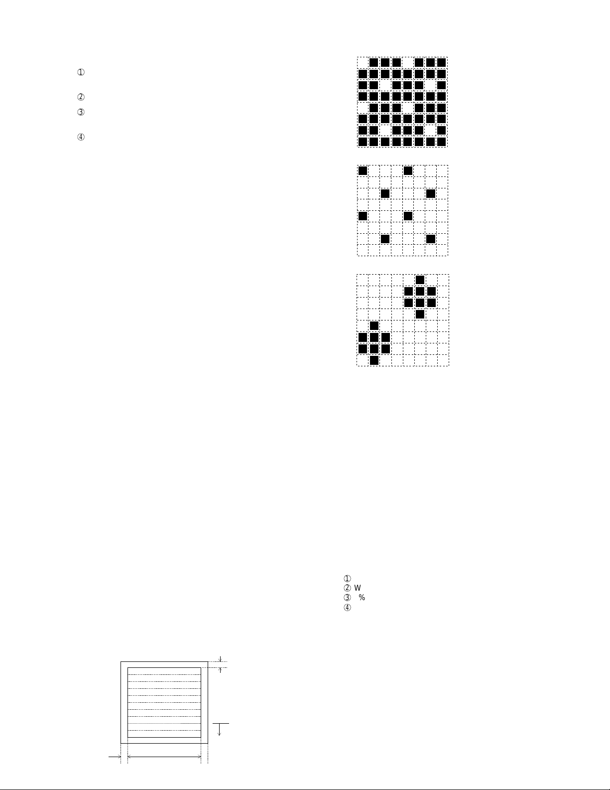
2-2. Print diagnosis
Rapid key 01: Area print mode
The effective printing area frame is printed in the specified sheet size.
1. Full Black pattern
2. Intermediate tone 2 pattern
3. Intermediate tone 1 pattern
4. Mesh point pattern
5. Longitudinal strip 2 pattern
6. Lateral strip 2 pattern
7. Lateral strip 1 pattern
8. Full white pattern
4mm ± 2
208mm
4mm ± 2.5
Pattern is
repeated.
1. [Full black pattern]
2. [Intermediate tone 2 pattern]
The left pattern is repeated.
3. [Intermediate tone 1 pattern]
The left pattern is repeated.
4. [Mesh point pattern]
The left pattern is repeated.
5. [Longitudinal strip 2 pattern]
Black 2 dot and white 2 dot are repeated in line.
6. [Lateral strip 2 pattern]
Black 2 line and white 2 line are repeated.
7. [Lateral strip 1 pattern]
Black 1 line and white 1 line are repeated.
8. [Full White pattern]
Rapid key 02: Check pattern 1
The lateral stripe 2 pattern is printed on one sheet.
(Black 2 line and white 2 line are repeated.)
Rapid key 03: Check pattern 2
The lateral stripe 2 pattern is printed on multiple pages.
Press the STOP key to end the printing.
Rapid key 04: Check pattern 3
The intermediate tone 1 is printed on one sheet.
Rapid key 05: Paper feed aging
The mode is used for aging related to the printing. In this mode, the
following modes are provided.
1
Blank paper aging mode (ALL WHITE AGING)
2
Whole black print aging mode (ALL BLACK AGING)
3
5% printing aging mode (5% AGING)
4
4% printing aging mode (4% AGING)
After selecting the paper-pass aging mode in the print diagnosis mode,
input the number of each mode above with the ten-key, and the mode
will be executed. The detailed specifications of each mode are described
as follows. Here, the operation in each mode is stopped only when the
STOP key is pressed by the operator or a printing-impossible error occurs.
• Blank paper aging mode
In the mode, printing is continued in the whole white (white paper)
printing pattern until the STOP key is pressed by the operator . (In the
printing area)
• Whole black printing aging mode
In the mode, printing is continued in the whole black (whole black)
printing pattern until the STOP key is pressed by the operator . (In the
printing area)
2 – 7
Page 20
FO-6600U
Rapid key 6: Bias adjust mode
The mode is used to adjust the printing density of the printed image. The
image printing density is adjustable in six steps of 1 to 6.
For details, refer to the following table. (For selection, use the keys 1 thru
6.)
Image printing density Thin ←→Thick
123456
Default value O
Rapid key 7: Life set mode
The mode is used to set the life counter of the printer and the counter of
the auto feeder at desired values. For setting, proceed with the following
procedure.
1
When the life counter setting mode is selected, the following will be
is displayed.
MACHINE
# key
FEEDER LIFE= 00123
TONER L IFE= 00123
DRUM
LIFE
LIFE
L
IFE1
LIFE2
LIFE3
= 00123
0
= 00123
0
= 00123
0
= 00123
0
= 00123
0
0
0
key
The cursor blinks at the top data.
Seven counters can be selected with the "#" and "
2
In the state 1, input a desired setting number of 6 digits with the ten-
" keys.
key.
3
After input of 6 digits, shift to another counter with the "#" and " "
keys as necessary. When all necessary counters are completely input, press the START key.
4
"STORED" will be displayed with the set values stored into the
memory. For checking, retry this mode.
Note:
The counter shows the operational state of the printer (how many sheets
have been printed since start of use? and others). The ordi-nary memory
does not reset the counter. For clearing, set 0 in this mode or use the life
counter clear mode in Item 3-9. (Accordingly, it is necessary to reset the
counter or do the clear process in addition to the ordinary memory clear
if the content in the memory on the control PWB is broken because of
PWB repair, etc. (In the production stage, it is necessary to execute this
in the last process.)
Rapid key 08: Life all clear
The mode is used to clear the life counter of the printer of the counter
of the auto feeder.
Note: The counter shows the operational state of the printer (e.g. how
many sheets have been printed since start of use?). The ordinary memory does not reset the counter. For clearing, set 0 in
the mode 8 or execute this mode. (Accordingly, it is nec-essary
to reset this counter in addition to the ordinary memory clear if
the content in the memory on the control PWB is broken because of PWB repair, etc. (In the production stage, it is necessary to execute this in the last process.)
Rapid key 09: Life entry mode
(For Serviceman temporary counter)
The mode is used to set a desired value for the judgment value (alarm
judgment counter value) of the general purpose life counters 1 thru 3 of
the printer. If the life of a consumable part (developer,imprinter, etc) is
set, the model which has the error display and RMS function will inform
RMS when the counter reaches the set value. For setting, proceed with
the following procedure.
1
When the life counter setting mode is selected, the following will be
displayed.
# key
LI FE1= 00000
LI FE2= 00000
LI FE3= 00000
0
0
0
key
The cursor blinks at the top data.
Three counters can be selected with the "#" and " " keys.
2
In the state 1 , input a desired setting number of 6 digits with the tenkey.
3
After input of 6 digits, shift to another counter with the "#" and " "
keys as necessary. When all necessary counters are completely input, press the START key.
4
"STORED" will be displayed with the set values stored into the
memory. For checking, retry this mode.
Note: The counter shows the operational state of the printer (how many
sheets have been printed since start of use? and oth-ers). The
ordinary memory does not reset the counter. For clearing, set 0
in this mode or use the life counter clear mode in Item 3-9. (Accordingly, it is necessary to reset the counter or do the clear
process in addition to the ordinary memory clear if the content
in the memory on the control PWB is broken be-cause of PWB
repair, etc. (In the production stage, it is neces-sary to execute
this in the last process.)
Rapid key 10: Top adjust mode
As the method to adjust the top margin for printing, adjust top-margin
adjusting VR on the PWB. If this mode is used at this time, adjust-ment
is possible without the printing test every time when VR is turned.
For the practical use, determine the adjusting value on the basis of the
old data, and adjust to the determined value in this mode. Then, check it
with the printing test.
Rapid key 11: Life clear mode
The mode is used to respectively clear the life counter of the printer and
the counter of the auto feeder. For setting, proceed with the following
procedure.
1
When the life counter clearing mode is selected, the following will be
is displayed.
Seven counters can be selected with the "#" and "
LEAR
C
DRUM
LIFE
LIFE
IFE1
L
LIFE2
LIFE3
LEAR
C
LEAR
C
LEAR
C
LEAR
C
C
C
MACHINE
# key
FEEDER L I FE LEAR
TONER L I FE LEAR
2
In the state 1, input the CLEAR key, and the counter will be respectively cleared.
3
After one clear, move the cursor to another counter with the "#" and
" " keys as necessary, and then press the CLEAR key. When the
necessary counters are completely cleared, press the STOP key.
" keys.
key
2 – 8
Page 21
3. How to make soft switch setting
T o enter the softswitch mode, make the following key entries in se-quence.
FO-6600U
Press
FUNCTION
9 8 7 START 0 1START
S F T S W 1 = 0 0 0 0 0 0 0 0
S F T S W 1 = 1 0 0 0 0 0 0 0
S F T S W 1 = 1 0 0 0 0 0 0 0
S F T S W 1 = 1 0 0 0 0 0 0 0
S F T S W 1 = 1 0 0 0 0 0 0 0
S F T S W 2 = 0 0 0 0 0 0 0 0
S F T S W 99 = 0 0 0 0 0 0 0 0
Press FUNCTION key.
Press key.
Press key.
Bit1 - 8 are set.
Press key during setting.
START
Soft SW2 - 99 are set.
To finish the settings halfway between
SW 1 and SW99, press the STOP key.
In this case, the setting being done to
the SW No. on display will be nullified
while settings done to the preceding
SW Nos. remain in effect.
• SW1 to SW13: For line 1
• SW14 to SW26: For line 2
The soft switch mode is terminated.
2 – 9
Page 22
FO-6600U
4. Soft switch description
• Soft switch
Note : SW1 to SW13 : For line 1, SW14 to SW26 : For line 2.
DA T A
SW
NO.
NO.
1 Recall interval Binary input 8 4 2 1 0 OPTION
2 No. = 1 2 3 4 (Data No.) 1 Set to 1~15
3 EX 0101 0
SW1 4 eg. Recall interval is set to 5 min. 1
5 Recall attempts Binary input 8421 0 OPTION
6 No. = 5678(Data No.) 0
7 EX 0010 1 Set to 0~15
8 eg. Recall attempt times is set to 2 times. 0
1 Dialing mode PULSE TONE 0
2 Receive mode AUTO MANUAL 1
3 ECM mode Off On 0 OPTION
SW2 4 Reserved 0
5 Polling security On Off 1 OPTION
6 Auto cover sheet No Yes 1 OPTION
7 JUNK-FAX function in manual reception Yes No 0
8 JUNK-FAX function Yes No 0 OPTION
1 Number of rings for auto-receive Binary input 8421 0 OPTION
2 (0: No ring receive) No. = 1234(Data No.) 0 Set to 0~15
3 EX 0001 0
SW3 4 eg. Number of rings for auto receive is set to 1. 1
5 Switch to auto-receive from manual receive Binary input 8421 0 OPTION
6 (0: No switch) No. = 5678(Data No.) 0 Set to 0~15
7 EX 0000 0
8 eg. Switch to auto receive is set to disable. 0
Communication results printout Printed at Printed at Printed at
1 No. 1 0 0 0 1 1 0
2 No. 2 0 0 1 0 1 0
SW4 3 No. 3 1 0 0 0 0 1
4 Image addition function to the communication On Off 1 OPTION
result table (for memory transmission only)
5 Reserved 0
6 TEL billing code function On Off 0 OPTION
7 Billing code position Before After 1 OPTION
8 Multi-TTI feature On Off 0 OPTION
1 Time display format 24 hours 12 hours-AM/PM 0
2 Date display format Month-Day-Year Day-Month-Year 1
3 Header print Off On 0
SW5 4 Footer print On Off 0
5 Relay data output No Yes 0
6 Substitute reception Off On 0
7 Substitute reception conditions Reception disable without TSI Reception enable without TSI 0
8 CSI transmission Off On 0
ITEM
error only
Switch setting and function
1
error/timer/
memory sion mode
only only
transmis- every time
0
Not printed
Printed OPTION
Initial
setting
Remarks
2 – 10
Page 23
FO-6600U
DATA
SW
NO.
NO.
1 MH fixed Yes No
2 H2 mode No Yes 0
3 Reserved 0
4 Reserved 0
SW6 Modem speed V. 33 V. 17 V. 29 V. 27ter
(DCS data reception speed)
5 No. 5 0 0 1 1 1 1 0 0 0 0 1
6 No. 6 1 1 0 0 0 0 0 0 0 0 0
7 No. 7 0 1 0 1 0 1 0 1 1 0 0
8 No. 8 0 0 0 0 1 1 1 1 0 0 0
Reception speed fixed NO V. 17- V. 29- V. 27ter-
1 No. 1 0 1 0 1 0
2 No. 2 0 1 1 0 0
3 DIS receive acknowledge in G3 transmission Twice Once in NSF reception, twice 0 Effective to
SW7 comm.
4 Non-modulated carrier in V.29 On Off 0
transmission mode
5 EOL detection timer 25sec 13sec 0
6 Protocol monitor On Off 0
7 Line monitor On Off 0
8 Max. length for TX/RX/Copy TX: 432mm, RX: unlimited TX/Copy: 432mm, RX: 1.5m 0
Compromise Equalizer constant (ROM) variable (SRAM)
1 No. 1 0 0 1 1 0
2 No. 2 0 1 0 1 1
3 Reserved 0
SW8 4 Pause time 2 sec
5 Signal transmission level Binary input 8 4 2 1 1
6 No. = 5 6 7 8 (Data No.) 0
7 EX 1010 1
8 Set to -(n+3)dBm 0
ITEM
1440012000 1440012000
(1 sec from the second pause)
Switch setting and function
1
(depend on remote machine)
9600 7200 9600 7200 4800 2400
14400BPS 9600BPS 4800BPS
in DIS reception international
No Filter 1.8Km 3.6Km 7.2Km
4 sec
(2 sec from the second pause)
eg. Signal transmission level is set to -11dBm
0
Initial
setting
0
0
Remarks
Default 14400
BPS MODEM
machine-1000
(V. 17-14400)
When 14400BPS
MODEM used,
setting to
14400BPS is
ignore.
2 – 11
Page 24
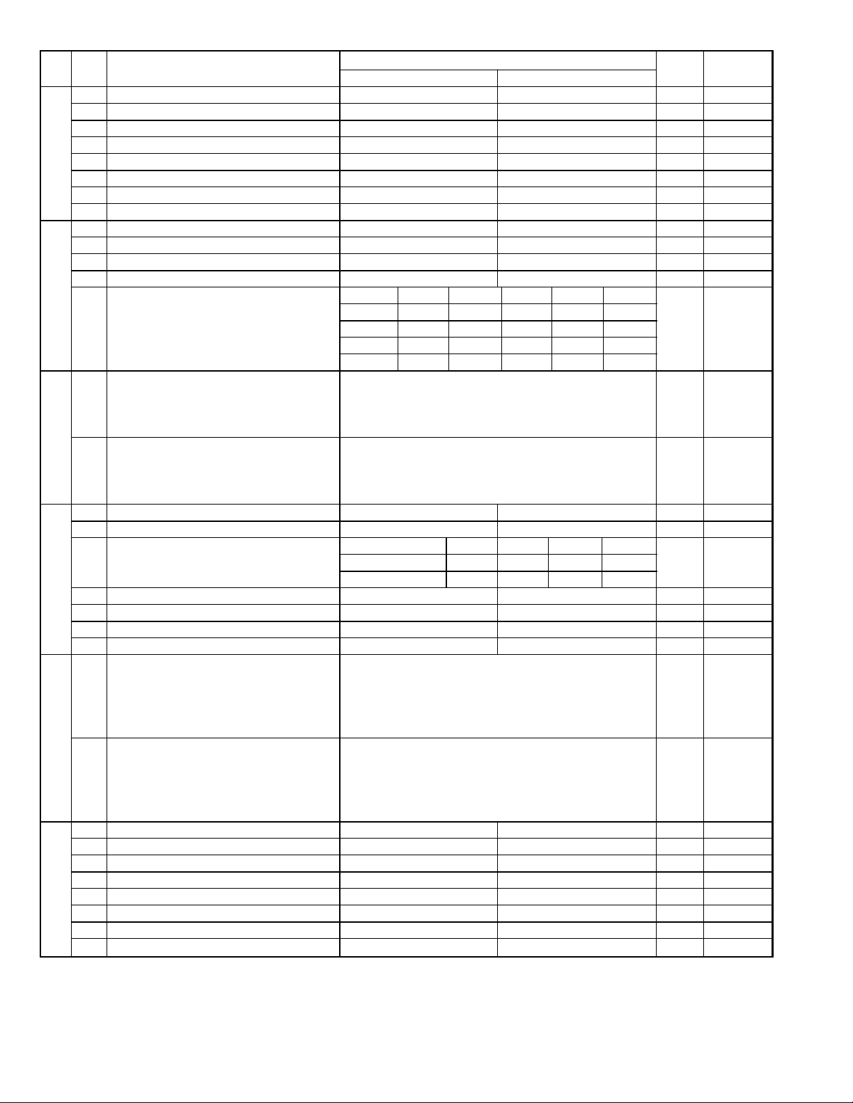
FO-6600U
DA T A
SW
NO.
NO.
1 CED tone signal interval 500ms 75ms 0
2 CI signal OFF detect enable time 350ms or more 700ms or more 0
3 Equalizer freeze On Off 0
SW9 4 Equalizer freeze conditions All 7200bps 0
5 Reserved 0
6 CED detection time 500ms 1000ms 0
7 Reserved 0
8 Reserved 0
1 Reserved 0
2 Reserved 0
3 Reserved 0
4 Reserved 0
SW10
SW11
SW12
SW13
SW14
Distinctive ringing OFF
5 No. 5 0 0 1 0 1 0
6 No. 6 0 0 0 1 1 0
7 No. 7 0 0 0 0 0 0
8 No. 8 0 1 0 0 0 0
1 Memory retransmission times Binary input 8421 1 OPTION
2 No. = 1234(Data No.) 0
3 EX 1010 1
4 eg. Retransmission time set to 10 times. 0
5 Memory retransmission interval Binary input 8421 0 OPTION
6 No. = 5678(Data No.) 0
7 EX 0000 0
8 eg. Retransmission interval set to 5 min. 0
1 Reserved 0
2 Reserved 0
Alarm buzzer 3sec 1sec No BEEP No BEEP
3 No. 3 0 0 1 1 0
4 No. 4 0 1 0 1 0
5 Action when RTN received Handle to no error Handle to error 0
6
V.34 mode function in case of manual communication
7 V.34 mode function On Off 1
8 V.34 control channel communication speed 2400bps 1200bps 0
1 V.34 mode sending speed Sending speed = 2400 (bps) x N 1
2 Example: 1
3 2400 (bps) x 12 = 28800 (bps) 1
4 2400 (bps) is set for N = 0. 0
5 V.34 mode receiving speed Receiving speed = 2400 (bps) x N 1
6 Example: 1
7 2400 (bps) x 12 = 28800 (bps) 1
8 2400 (bps) is set for N = 0. 0
1 Reserved 0
2 Reserved 1
3 Reserved 0
4 Reserved 1
5 Reserved 0
6 Reserved 0
7 Reserved 1
8 Reserved 0
ITEM
On Off 1
33600 (bps) is set for N = 15.
33600 (bps) is set for N = 15.
Switch setting and function
1
STANDARD
RING1 RING2 RING3
0
Initial
setting
Remarks
2 – 12
Page 25
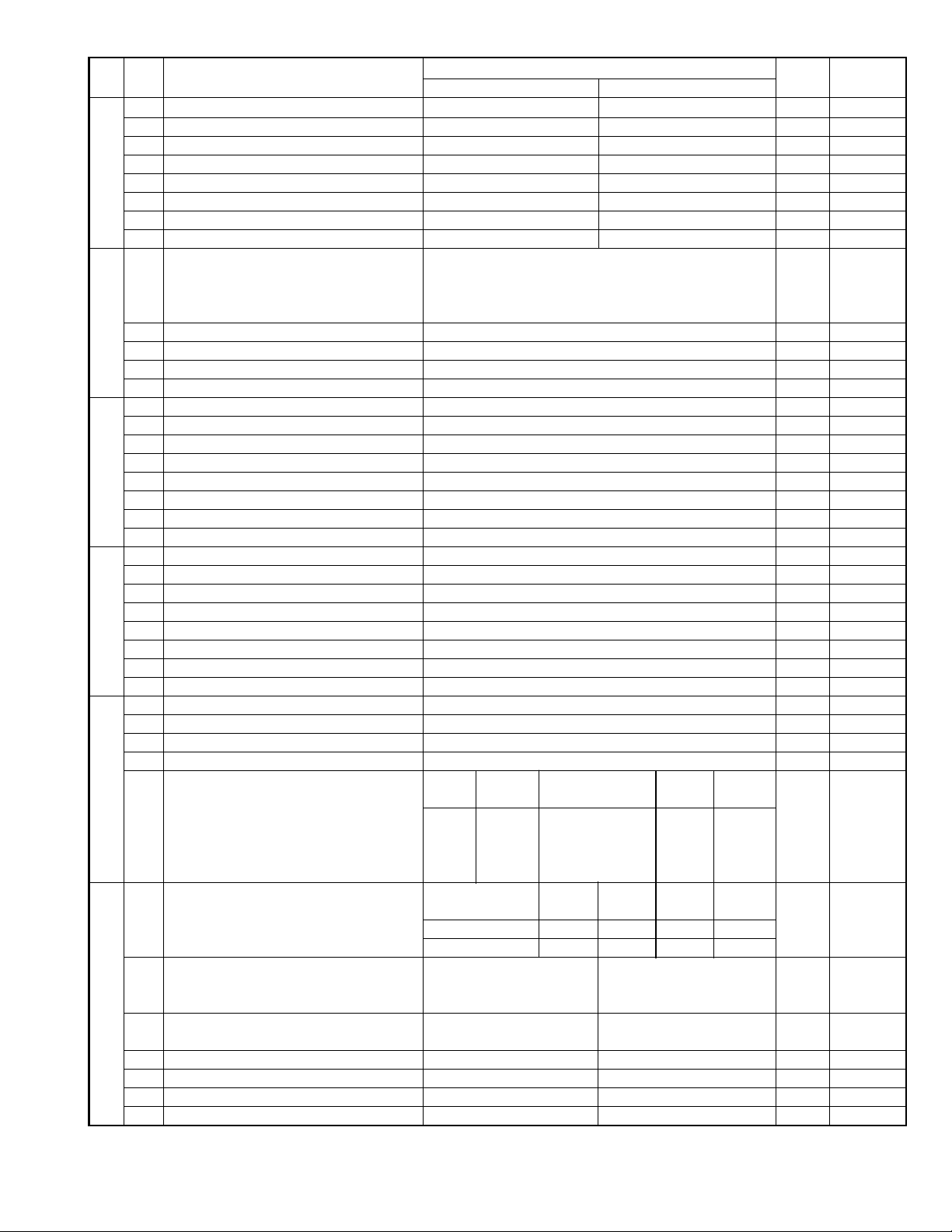
FO-6600U
SW
NO.
SW15
SW16
SW17
SW18
SW19
SW20
DATA
NO.
1 Dialing mode PULSE TONE 0
2 Reserved 1
3 Reserved 0
4 Reserved 0
5 Reserved 1
6 Reserved 1
7 Reserved 0
8 Reserved 0
1 Number of rings for auto-receive Binary input 8 4 2 1 0 OPTION
2 (0 : No ring receive) No. = 1 2 3 4 (Data No.) 0 Set to 0 ~15
3 EX 0001 0
4 eg. Number of rings for auto receive is set to 1. 1
5 Reserved 0
6 Reserved 0
7 Reserved 0
8 Reserved 0
1 Reserved 0
2 Reserved 0
3 Reserved 1
4 Reserved 1
5 Reserved 0
6 Reserved 0
7 Reserved 1
8 Reserved 0
1 Reserved 0
2 Reserved 1
3 Reserved 0
4 Reserved 0
5 Reserved 0
6 Reserved 0
7 Reserved 0
8 Reserved 0
1 Reserved 0
2 Reserved 0
3 Reserved 0
4 Reserved 0
Modem speed V. 33 V. 17 V. 29 V. 27ter
(DCS data reception speed)
5 No. 5 0 0 1 1 1 1 0 0 0 0 1
6 No. 6 1 1 0 0 0 0 0 0 0 0 0
7 No. 7 0 1 0 1 0 1 0 1 1 0 0
8 No. 8 0 0 0 0 1 1 1 1 0 0 0
Reception speed fixed NO V. 17- V. 29- V. 27ter-
1 No. 1 0 1 0 1 0
2 No. 2 0 1 1 0 0
3 DIS receive acknowledge in G3 transmission Twice Once in NSF reception, twice 0 Effective to
4 Non-modulated carrier in V.29 On Off 0
transmission mode
5 EOL detection timer 25sec 13sec 0
6 Protocol monitor On Off 0
7 Line monitor On Off 0
8 Reserved 0
ITEM
1440012000 1440012000
Switch setting and function
1
9600 7200 9600 7200 4800 2400
14400PS 9600BPS 4800BPS
in DIS reception international
0
Initial
setting
Remarks
Default 14400
BPS MODEM
machine-1000
(V. 17-14400)
When 14400BPS
MODEM used,
setting to
14400BPS is
ignore.
comm.
2 – 13
Page 26
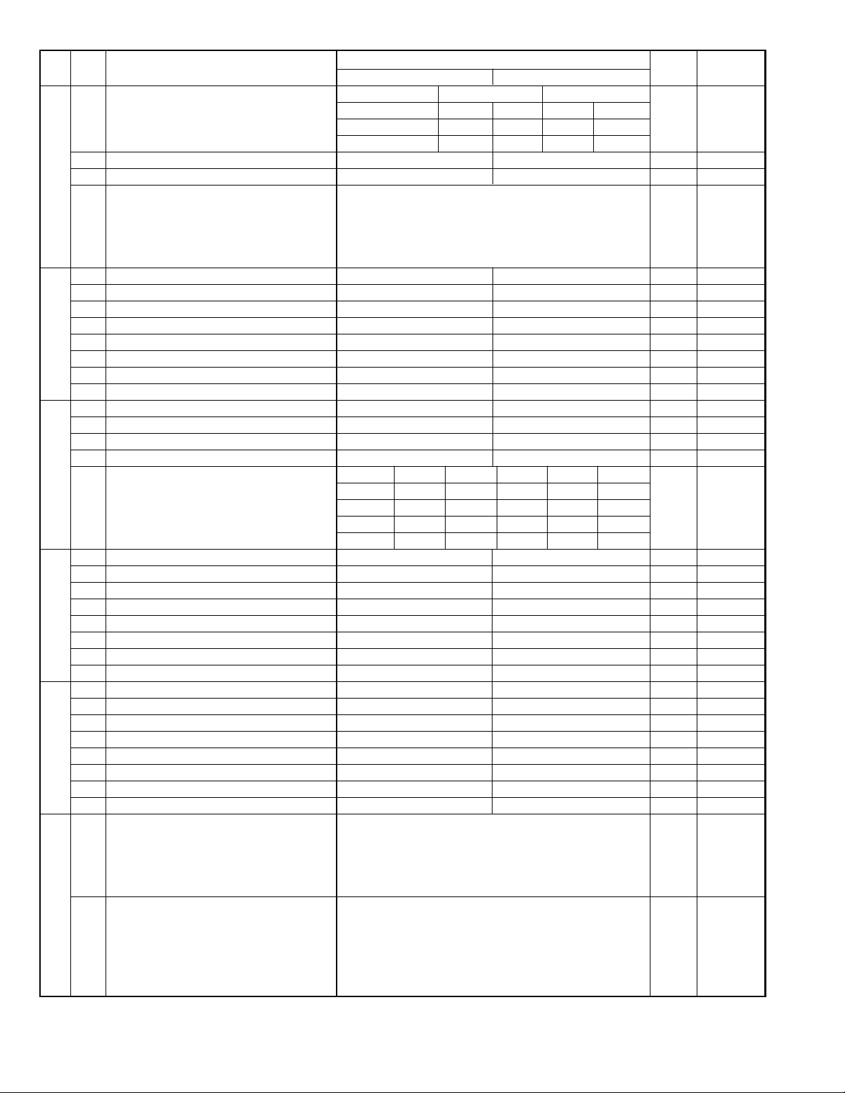
FO-6600U
SW
NO.
SW21
SW22
SW23
SW24
SW25
SW26
DA T A
NO.
Compromise Equalizer constant (ROM) variable (SRAM)
1 No. 1 0 0 1 1 0
2 No. 2 0 1 0 1 1
3 Reserved 0
4 Pause time 2 sec
5 Signal transmission level Binary input 8421 1
6 No. = 5678(Data No.) 0
7 EX 1010 1
8 Set to -(n+3)dBm 0
1 CED tone signal interval 500ms 75ms 0
2 CI signal OFF detect enable time 350ms or more 700ms or more 0
3 Equalizer freeze On Off 0
4 Equalizer freeze conditions All 7200bps 0
5 Reserved 0
6 CED detection time 500ms 1000ms 0
7 Reserved 0
8 Reserved 0
1 Reserved 0
2 Reserved 0
3 Reserved 0
4 Reserved 0
Distinctive ringing OFF
5 No. 5 0 0 1 0 1 0
6 No. 6 0 0 0 1 1 0
7 No. 7 0 0 0 0 0 0
8 No. 8 0 1 0 0 0 0
1 Reserved 1
2 Reserved 0
3 Reserved 1
4 Reserved 0
5 Reserved 0
6 Reserved 0
7 Reserved 0
8 Reserved 0
1 Reserved 0
2 Reserved 0
3 Reserved 0
4 Reserved 0
5 Reserved 0
6 Reserved 1
7 V.34 mode function On Off 1
8 V.34 control channel communication speed 2400bps 1200bps 0
1 V.34 mode sending speed Sending speed = 2400 (bps) x N 1
2 Example: 1
3 2400 (bps) x 12 = 28800 (bps) 1
4 2400 (bps) is set for N = 0. 0
5 V.34 mode receiving speed Receiving speed = 2400 (bps) x N 1
6 Example: 1
7 2400 (bps) x 12 = 28800 (bps) 1
8 2400 (bps) is set for N = 0. 0
ITEM
(1 sec from the second pause)
33600 (bps) is set for N = 15.
33600 (bps) is set for N = 15.
Switch setting and function
1
No Filter 1.8Km 3.6Km 7.2Km
4 sec
(2 sec from the second pause)
eg. Signal transmission level is set to -11dBm
STANDARD
RING1 RING2 RING3
0
setting
Initial
0
Remarks
2 – 14
Page 27

FO-6600U
DATA
SW
NO.
NO.
Line condition setting Line 1 TX/RX TX/RX TX/RX RX RX TX TX OPTION
1 No. 1 0 000111 0
2 No. 2 0 011001 0
3 No. 3 0 101010 0
SW27
SW28 4 No. 4 0 1 0 1 0
SW29
SW30
SW31
4 Preference line specification LINE 2 LINE 1 0
Key buzzer volume Off HIGH MIDDLE LOW
5 No. 5 0 0 1 1 1
6 No. 6 0 1 0 1 1
7 Reserved 0
8 Reserved 0
Speaker volume HIGH HIGH MIDDLE LOW
1 No. 1 0 0 1 1 1
2 No. 2 0 1 0 1 1
Handset volume HIGH HIGH MIDDLE LOW
3 No. 3 0 0 1 1 1
Ringer volume Off HIGH MIDDLE LOW
5 No. 5 0 0 1 1 1
6 No. 6 0 1 0 1 1
7 Reserved 0
8 Reserved 0
1 Line to be used in PC I/F mode LINE 2 LINE 1 0
2 PC I/F mode On Off 0 OPTION
3 Auto receive with PC I/F PC FAX 0 OPTION
4 Reserved 0
5 Reserved 0
6 Reserved 0
7 Reserved 0
8 Reserved 0
1 Reserved 0
2 Reserved 0
3 Continuous serial polling On Off 0
Dialing interval in continuous serial polling
4 No. 4 0 0 1 1 0
5 No. 5 0 1 0 1 0
6 Reserved 0
7 Reserved 0
8 Quick on-line Yes No 1
1 Reserved 0
2 Reserved 0
3 Reserved 0
4 Reserved 0
5 Reserved 1
6 Reserved 0
7 Reserved 1
8 Reserved 0
ITEM
Line 2 TX/RX RX TX TX/RX TX TX/RX RX
Switch setting and function
1
0minute
30minutes 60minutes 120minutes
0
Initial
setting
Remarks
When SW30-3
is ON to be set
by OPTION
setting
2 – 15
Page 28

FO-6600U
SW
NO.
SW32
SW33
SW34
SW35
SW36
DA T A
NO.
1 Print hold On Off 0 OPTION
2 Document transmission in Super G3 mode Yes No 0 Refer to
3 Reserved 0
4 Changeover of print cassette On Off 1 OPTION
Selection of print cassette W cassette Auto. TUL TLU UTL ULT LTU LUT Indicate of
5 No. 5 0 1 10000 0U...UPPER
6 No. 6 0 0 01100 0L...LOWER
7 No. 7 0 0 00011 0
8 No. 8 0 1 01010 0
Selection of print cassette SEPA. Auto. U→LL→U Indicate of
5 No. 5 0 0 0 0 U...UPPER
6 No. 6 0 1 0 0 L...LOWER
7 No. 7 0 0 1 0
8 No. 8 0 0 0 0
Heater mode Always on Always off Off timer OPTION
1 No. 1 0 0 1 0
2 No. 2 0 1 0 1
Density adjustment of print bias Binary input 4 2 1 set to 1~6.
3 No. = 3 4 5 (Data No.) 1: faint 6: deep 0 set to 0,7 is
4 EX 0 1 1 1 equal to 3
5 eg. Bias is set to level 3. 1 (001).
6 Drum life limit 0 near = 19,000 pcs. 0 near = 15,000 pcs. 0
7 0 limit = 20,000 pcs. 1 limit = 16,000 pcs. 0
8 Reserved 0
1 Start time of heater OFF timer Binary input 8 4 2 1 0 OPTION
2 (Upper digit of hour) No. = 1 2 3 4 (Data No.) 0
3 EX 0000 0
4 0
5 Start time of heater OFF timer Binary input 8 4 2 1 0 OPTION
6 (Lower digit of hour) No. = 5 6 7 8 (Data No.) 0
7 EX 0000 0
8 eg. Start time is set to 15: XX 0
1 Start time of heater OFF timer Binary input 8 4 2 1 0 OPTION
2 (Upper digit of minute) No. = 1 2 3 4 (Data No.) 0
3 EX 0000 0
4 0
5 Start time of heater OFF timer Binary input 8 4 2 1 0 OPTION
6 (Lower digit of minute) No. = 5 6 7 8 (Data No.) 0
7 EX 0000 0
8 eg. Start time is set to XX: 40 0
1 End time of heater OFF timer Binary input 8 4 2 1 0 OPTION
2 (Upper digit of hour) No. = 1 2 3 4 (Data No.) 0
3 EX 0000 0
4 0
5 End time of heater OFF timer Binary input 8 4 2 1 0 OPTION
6 (Lower digit of hour) No. = 5 6 7 8 (Data No.) 0
7 EX 0000 0
8 eg. End time is set to 21: XX 0
ITEM
MODE ON priority
1 near = 15,000 pcs. 1 near = 16,000 pcs.
0 limit = 20,000 pcs. 1 limit = 20,000 pcs.
Switch setting and function
1
0
Work in auto mode
except in this table.
Initial
setting
Remarks
Page 2-44.
priority
T...TRAY
2 – 16
Page 29

FO-6600U
SW
NO.
SW37
SW38
SW39
SW40
SW41
DATA
NO.
1 End time of heater OFF timer Binary input 8 4 2 1 0 OPTION
2 (Upper digit of minute) No. = 1 2 3 4 (Data No.) 0
3 EX 0000 0
4 0
5 End time of heater OFF timer Binary input 8 4 2 1 0 OPTION
6 (Lower digit of minute) No. = 5 6 7 8 (Data No.) 0
7EX00000
8 eg. End time is set to XX: 35 0
1 Reserved 1
2 Reserved 0
3 Reserved 0
4 Reserved 0
5 Reserved 0
6 Reserved 0
7 Reserved 0
8 Reserved 0
1 Reserved 0
2 Reserved 1
3 Reserved 0
4 Reserved 0
5 Reserved 0
6 Reserved 0
7 Reserved 0
8 Reserved 0
1 Reserved 1
2 Reserved 0
3 Reserved 0
4 Reserved 0
5 Reserved 0
6 Reserved 0
7 Reserved 0
8 Reserved 0
1 Reserved 0
2 Reserved 0
3 Reserved 1
4 Reserved 0
5 Reserved 0
6 Reserved 1
7 Reserved 0
8 Reserved 1
ITEM
Switch setting and function
1
0
Initial
setting
Remarks
2 – 17
Page 30
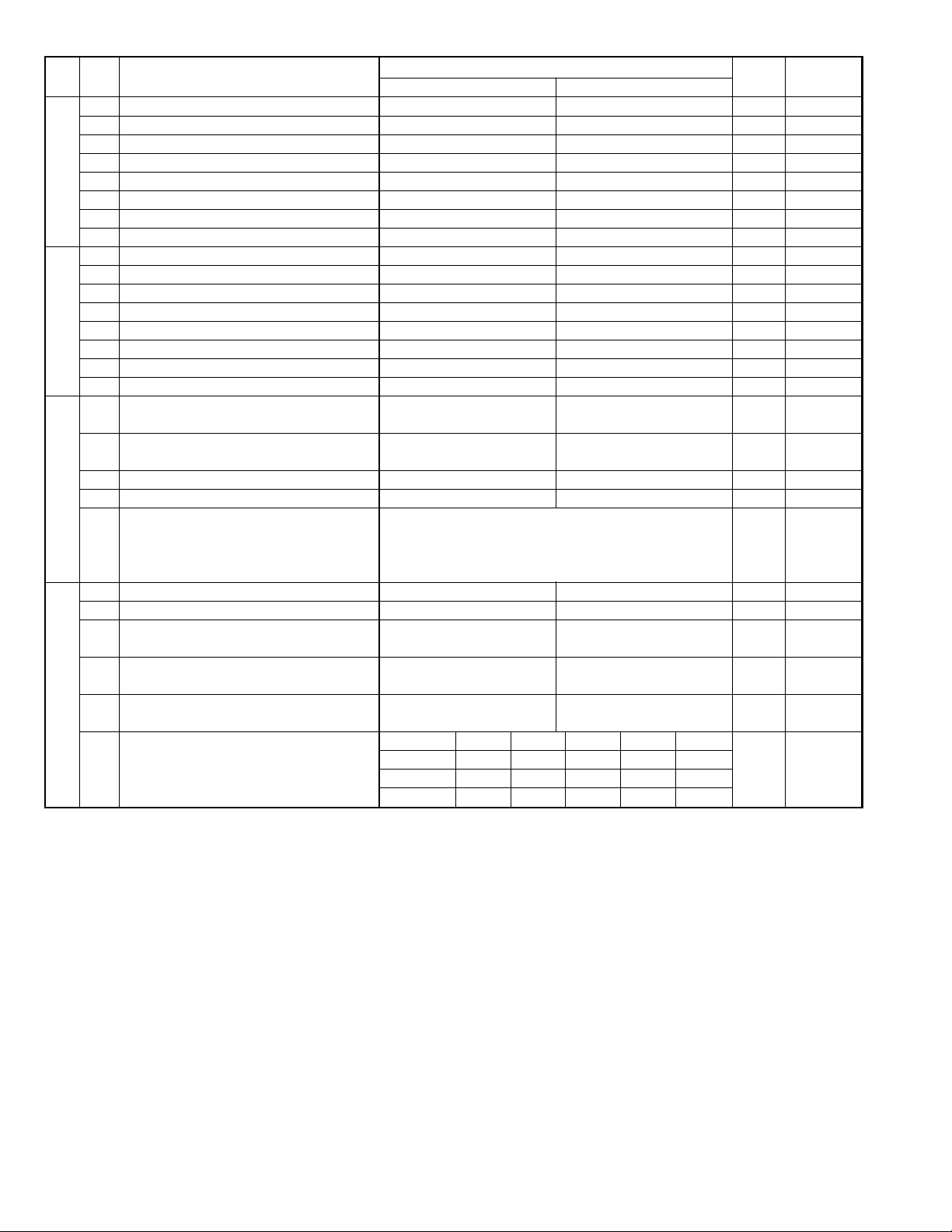
FO-6600U
SW
NO.
SW42
SW43
SW44
SW45
DA T A
NO.
1 Reserved 0
2 Reserved 0
3 Reserved 1
4 Reserved 0
5 Reserved 0
6 Reserved 1
7 Reserved 0
8 Reserved 1
1 Reserved 1
2 Reserved 0
3 Reserved 0
4 Reserved 0
5 Reserved 0
6 Reserved 1
7 Reserved 0
8 Reserved 1
1 Automatic printing of activity report Yes (When memory full) No (First data is cleared 0 OPTION
2 Printout of total time and total number of Off On 0
pages on activity report
3 Reserved 0
4 Department function On Off 0
5 Department ID digit Binary input 8 4 2 1 0 OPTION
6 No. = 5 6 7 8 (Data No.) 1 Set is 3~9.
7EX01000
8 eg. Department ID is set to 4 digits. 0
1 Picture quality priority mode Fine Standard 0 OPTION
2 Cut-off mode (when copy mode) Continue Cut-off 0 OPTION
3 Scanning ratio in memory input 1 : 1 Reduce 0 Memory
4 Verification STAMP Yes No 0 Invalid if not
5 Overseas communication mode selection Yes No 0 Refer to
function Page 2-44.
Reduce ratio (when copy mode) AUTO 100% 95% 89% 74%
6 No. 6 0 1 0 0 1 1
7 No. 7 0 0 1 0 1 0
8 No. 8 0 0 0 1 0 0
ITEM
Switch setting and function
1
when memory full)
0
Initial
setting
Remarks
scanning
mounted.
2 – 18
Page 31

FO-6600U
SW
NO.
SW46
SW47
SW48
SW49
SW50
SW51
DATA
NO.
1 Reserved 0
2 Reserved 0
Density adjustment (when Fine/STD mode) Normal Faint Deep Deep
3 No. 1 0 0 1 1 0
4 No. 2 0 1 0 1 0
Density adjustment (when Half-tone mode) Normal Faint Deep Deep
5 No. 3 0 0 1 1 0
6 No. 4 0 1 0 1 0
7 HTF correction in Half-tone mode On Off 1
8 MTF correction in Half-tone mode Strong Weak 0
1 Reserved 0
2 Reserved 0
3 Reserved 0
4 Reserved 0
5 Reserved 0
6 Reserved 0
7 Reserved 0
8 Reserved 0
1 Reserved 0
2 Reserved 0
3 Reserved 0
4 Reserved 0
5 Reserved 0
6 Reserved 0
7 Reserved 0
8 Reserved 0
1 Reserved 0
2 Reserved 0
3 Reserved 0
4 Reserved 0
5 Reserved 0
6 Reserved 0
7 Reserved 0
8 Reserved 0
1 Reserved 0
2 Reserved 0
3 Reserved 0
4 Reserved 0
5 Reserved 0
6 Reserved 0
7 Reserved 0
8 Reserved 0
1 Reserved 0
2 Reserved 0
3 Reserved 0
4 Reserved 0
5 Reserved 0
6 Reserved 0
7 Reserved 0
8 Reserved 0
ITEM
Switch setting and function
1
0
(when Dark
mode)
(when Dark
mode)
Initial
setting
Remarks
2 – 19
Page 32

FO-6600U
SW
NO.
SW52
SW53
SW54
SW55
SW56
SW57
DA T A
NO.
1 Reserved 0
2 Reserved 0
3 Reserved 0
4 Reserved 0
5 Reserved 0
6 Reserved 0
7 Reserved 0
8 Reserved 0
1 Reserved 0
2 Reserved 0
3 Reserved 0
4 Reserved 0
5 Reserved 0
6 Reserved 0
7 Reserved 0
8 Reserved 0
1 Reserved 0
2 Reserved 0
3 Reserved 0
4 Reserved 0
5 Reserved 0
6 Reserved 0
7 Reserved 0
8 Reserved 0
1 Reserved 0
2 Reserved 0
3 Reserved 0
4 Reserved 0
5 Reserved 0
6 Reserved 0
7 Reserved 0
8 Reserved 0
1 Reserved 1
2 Reserved 1
3 Reserved 1
4 Reserved 1
5 Printing when toner empty Printing Stop 0
Reduction of print data AUTO 100%
6 No. 6 0 1 0 0 1 0
7 No. 7 0 0 1 0 1 0
8 No. 8 0 0 0 1 0 0
1 Reserved 0
2 Reserved 0
3 Reserved 0
4 Reserved 0
5 Reserved 0
6 Reserved 0
7 Reserved 0
8 Reserved 0
ITEM
Switch setting and function
1
94%
(92%)
88%
0
(86%)
73%
(72%)
Initial
setting
Remarks
The number in
() is applicable
for the footer
print on. AUTO
is equivalent to
100 %.
2 – 20
Page 33

FO-6600U
SW
NO.
SW58
SW59
SW60
SW61
SW62
SW63
DATA
NO.
1 Reserved 0
2 Reserved 0
3 Reserved 0
4 Reserved 0
5 Reserved 0
6 Reserved 0
7 Reserved 0
8 Reserved 0
1 Reserved 0
2 Reserved 0
3 Reserved 0
4 Reserved 0
5 Reserved 0
6 Reserved 0
7 Reserved 0
8 Reserved 0
1 Reserved 0
2 Reserved 0
3 Reserved 0
4 Reserved 0
5 Reserved 0
6 Reserved 0
7 Reserved 0
8 Reserved 0
1 Reserved 0
2 Reserved 0
3 Reserved 0
4 Reserved 0
5 Reserved 0
6 Reserved 0
7 Reserved 0
8 Reserved 0
1 Reserved 0
2 Reserved 0
3 Reserved 0
4 Reserved 0
5 Reserved 0
6 Reserved 0
7 Reserved 0
8 Reserved 0
1 Reserved 0
2 Reserved 0
3 Reserved 0
4 Reserved 0
5 Reserved 0
6 Reserved 0
7 Reserved 0
8 Reserved 0
ITEM
Switch setting and function
1
0
Initial
setting
Remarks
2 – 21
Page 34

FO-6600U
SW
NO.
SW64
SW65
SW66
SW67
SW68
SW69
DA T A
NO.
1 Reserved 0
2 Reserved 0
3 Reserved 0
4 Reserved 0
5 Reserved 0
6 Reserved 0
7 Reserved 0
8 Reserved 0
1 Reserved 0
2 Reserved 0
3 Reserved 0
4 Reserved 0
5 Reserved 0
6 Reserved 0
7 Reserved 0
8 Reserved 0
1 Reserved 0
2 Reserved 0
3 Reserved 0
4 Reserved 0
5 Reserved 0
6 Reserved 0
7 Reserved 0
8 Reserved 0
1 Reserved 0
2 Reserved 0
3 Reserved 0
4 Reserved 0
5 Reserved 0
6 Reserved 0
7 Reserved 0
8 Reserved 0
1 Reserved 0
2 Reserved 0
3 Reserved 0
4 Reserved 0
5 Reserved 0
6 Reserved 0
7 Reserved 0
8 Reserved 0
1 Cassette define (LTR/A4): Tray A4 LTR 0
2 Cassette define (LTR/A4): Upper A4 LTR 0 When W
3 Cassette define (LTR/A4): Lower A4 LTR 0 Ignore when
4 Separation of image area in the half-tone On Off 1
5 Removal of notch in the binary mode On Off 1
6 Reserved 1
7 Reserved 1
8 Reserved 0
ITEM
Switch setting and function
1
0
Initial
setting
Remarks
cassette
W cassette.
2 – 22
Page 35

FO-6600U
SW
NO.
SW70
SW71
SW72
SW73
DATA
NO.
1 Reserved 1
2 Reserved 1
3 Reserved 1
4 Reserved 1
5 Reserved 0
6 Reserved 0
7 Reserved 0
8 Reserved 0
Black line detection Continued black line count when detected
(When transmission scanning) 1 2 3 4567
1 No. 1 0 0 0 00000 0
2 No. 2 0 0 0 01111 0
3 No. 3 0 0 1 10011 1
4 No. 4 0 1 0 10101 1
All white page detection All white line count ratio against total count of page to
(When transmission scanning) judge the white page
5 No. 5 0 0 0 00000 0
6 No. 6 0 0 0 01111 1
7 No. 7 0 0 1 10011 0
8 No. 8 0 1 0 10101 1
5 No. 5 1 1 1 11111
6 No. 6 0 0 0 01111
7 No. 7 0 0 1 10011
8 No. 8 0 1 0 10101
Black line detection Continued black line count when detected
(When copy scanning) 1 2 3 4567
1 No. 1 0 0 0 00000 0
2 No. 2 0 0 0 01111 0
3 No. 3 0 0 1 10011 1
4 No. 4 0 1 0 10101 1
White page detect All white line count ratio against total count of page to
(When copy scanning) judge the white page
5 No. 5 0 0 0 00000 0
6 No. 6 0 0 0 01111 1
7 No. 7 0 0 1 10011 0
8 No. 8 0 1 0 10101 1
5 No. 5 1 1 1 11111
6 No. 6 0 0 0 01111
7 No. 7 0 0 1 10011
8 No. 8 0 1 0 10101
1 Reserved 1
2 Reserved 0
3 Reserved 0
4 Reserved 0
5 Reserved 0
6 Reserved 0
7 Reserved 0
8 Reserved 1
ITEM
Unused
All white line count ratio against total count of page to
judge the white page
Unused
All white line count ratio against total count of page to
judge the white page
Switch setting and function
1
1.0% 1.5% 2.0% 2.5% 3.0% 3.5% 4.0%
4.5% 5.0% 5.5% 6.0% 7.0% 8.0% 9.0%
1.0% 1.5% 2.0% 2.5% 3.0% 3.5% 4.0%
4.5% 5.0% 5.5% 6.0% 7.0% 8.0% 9.0%
0
Unused
10.0%
Unused
10.0%
Initial
setting
Remarks
2 – 23
Page 36

FO-6600U
SW
NO.
SW74
SW75
SW76
SW77
SW78
SW79
DA T A
NO.
1 Reserved 0
2 Reserved 1
3 Reserved 1
4 Reserved 0
5 Reserved 0
6 Reserved 0
7 Reserved 0
8 Reserved 0
1 Reserved 0
2 Reserved 1
3 Reserved 0
4 Reserved 0
5 Reserved 0
6 Reserved 0
7 Reserved 0
8 Reserved 0
1 Reserved 1
2 Reserved 1
3 Reserved 1
4 Reserved 1
5 Reserved 1
6 Reserved 1
7 Reserved 0
8 Reserved 0
1 Reserved 0
2 Reserved 0
3 Reserved 0
4 Reserved 0
5 Reserved 0
6 Reserved 0
7 Reserved 0
8 Reserved 0
1 Secure billing code Yes No 0
2 Pause with Z key Yes No 0
3 Reserved 0
4 Z key pause time Binary input 16 8 4 2 1 0
5 250 ms unit No. = 45678 (Data No.) 0
6 EX 00000 0
7 eg. Pause time 250 ms 0
8 Time = (n + 1) x 250 ms 0
1 Reserved 1
2 Reserved 1
3 Reserved 1
4 Reserved 1
5 Reserved 0
6 Reserved 0
7 Reserved 0
8 Reserved 0
ITEM
Switch setting and function
1
0
setting
Initial
Remarks
Only when
special billing
code is given.
Only when the
special billing
code is given
The ordinary
pause is not
affected.
2 – 24
Page 37

FO-6600U
SW
NO.
SW80
SW81
SW82
SW83
SW84
SW85
DATA
NO.
1 Reserved 0
2 Reserved 0
3 Reserved 1
4 Reserved 1
5 Reserved 0
6 Reserved 1
7 Reserved 1
8 Reserved 0
1 Reserved 0
2 Reserved 0
3 Reserved 0
4 Reserved 0
5 Reserved 1
6 Reserved 0
7 Reserved 0
8 Reserved 0
1 Reserved 1
2 Reserved 0
3 Reserved 0
4 Reserved 1
5 Reserved 0
6 Reserved 0
7 Reserved 1
8 Reserved 1
1 Reserved 0
2 Reserved 1
3 Reserved 0
4 Reserved 0
5 Reserved 0
6 Reserved 1
7 Reserved 1
8 Reserved 0
1 Reserved 0
2 Reserved 0
3 Reserved 1
4 Reserved 0
5 Reserved 0
6 Reserved 0
7 Reserved 0
8 Reserved 1
1 Reserved 0
2 Reserved 0
3 Reserved 1
4 Reserved 0
5 Reserved 0
6 Reserved 0
7 Reserved 0
8 Reserved 1
ITEM
Switch setting and function
1
0
Initial
setting
Remarks
2 – 25
Page 38

FO-6600U
SW
NO.
SW86
SW87
SW88
SW89
SW90
SW91
DA T A
NO.
1 F.A.S.T. (RMS) mode On Off 0
2 F.A.S.T. (RMS) line LINE 2 LINE 1 0
3 Day light saving time feature On Off 0
4 Separate mode On Off 0 OPTION
5 Reserved 0
6 Reserved 0
7 CNG send when manual TX On Off 1
8 Ringer of line 2 On Off 0
1 Reserved 0
Addition of header to various lists Without
2 No. 2 0 0 1 1 0
3 No. 3 0 1 0 1 0
Relay instruction transmission AUTO Line 1 Line 2 Not used
line specification (AUTO)
4 No. 4 0 0 1 1 0
5 No. 5 0 1 0 1 1
6 Reserved 1
7 Reserved 0
8 Reserved 0
1 Reserved 0
2 Reserved 1
3 Reserved 0
4 Reserved 0
5 Reserved 0
6 Reserved 0
7 Reserved 0
8 Reserved 0
1 Reserved 0
2 Reserved 0
3 Reserved 0
4 Reserved 0
5 Reserved 0
6 Reserved 0
7 Reserved 0
8 Reserved 0
1 Reserved 0
2 Reserved 0
3 Reserved 0
4 Reserved 0
5 Reserved 0
6 Reserved 0
7 Reserved 0
8 Reserved 0
1 Reserved 0
2 Reserved 0
3 Reserved 0
4 Reserved 0
5 Reserved 0
6 Reserved 0
7 Reserved 0
8 Reserved 0
ITEM
Switch setting and function
1
Information Information
addition
of line 1 of line 2
0
Without
addition
Initial
setting
Remarks
2 – 26
Page 39

FO-6600U
SW
NO.
SW92
SW93
SW94
SW95
SW96
SW97
DATA
NO.
1 Reserved 0
2 Reserved 0
3 Reserved 0
4 Reserved 0
5 Reserved 0
6 Reserved 0
7 Reserved 0
8 Reserved 0
1 Reserved 0
2 Reserved 0
3 Reserved 0
4 Reserved 0
5 Reserved 0
6 Reserved 0
7 Reserved 0
8 Reserved 0
1 Reserved 0
2 Reserved 0
3 Reserved 0
4 Reserved 0
5 Reserved 0
6 Reserved 0
7 Reserved 0
8 Reserved 0
1 Reserved 0
2 Reserved 0
3 Reserved 0
4 Reserved 0
5 Reserved 0
6 Reserved 0
7 Reserved 0
8 Reserved 0
1 Reserved 0
2 Reserved 0
3 Reserved 0
4 Reserved 0
5 Reserved 0
6 Reserved 0
7 Reserved 0
8 Reserved 0
1 Reserved 0
2 Reserved 0
3 Reserved 0
4 Reserved 0
5 Reserved 1
6 Reserved 1
7 Reserved 1
8 Reserved 1
ITEM
Switch setting and function
1
0
Initial
setting
Remarks
2 – 27
Page 40

FO-6600U
SW
NO.
SW98
SW99
DA T A
NO.
1 Reserved 0
2 Reserved 0
3 Reserved 0
4 Reserved 0
5 Reserved 0
6 Reserved 0
7 Reserved 0
8 Reserved 0
1 Reserved 0
2 Reserved 0
3 Reserved 0
4 Reserved 0
5 Reserved 0
6 Reserved 0
7 Reserved 0
8 Reserved 0
ITEM
Switch setting and function
1
0
Initial
setting
Remarks
2 – 28
Page 41

FO-6600U
• Soft switch function description
SW1 No. 1 ~ No. 4 Recall interval
Choice is made for a recall interval for speed and rapid dial-numbers.
Use a binary number to program this. If set to 0 accidentally, 1 will be
assumed.
SW1 No. 5 ~ No. 8 Recall attempts
Choice is made as to how many recall attempts should be made. Use a
binary number to program this.
SW2 No. 1 Dialing mode
Switch the type according to the telephone circuit connected to the facsimile.
0: PULSE DIAL
1: TONE DIAL
SW2 No. 2 Receive mode
Auto/manual receiving mode is set.
SW2 No. 3 ECM mode
Used to determine ECM mode function. Refer to the following table.
SW2-No.3 ECM MODE 0 000000011111111
SW6-No.1 MH FIXED 0 101010101010101
ECM MMR mode Yes No Yes No No No No No No No No No No No No No
Compre- ECM MR mode Yes No Yes No Yes No Yes No No No No No No No No No
ssion ECM MMH mode Yes Yes No No Yes Yes No No No No No No No No No No
method ECM MH mode Yes Yes Yes Yes Yes Yes Yes Yes No No No No No No No No
MR mode Yes No Yes No Yes No Yes No Yes No Yes No Yes No Yes No
MH mode Yes Yes Yes Yes Yes Yes Yes Yes Yes Yes Yes Yes Yes Yes Yes Yes
(Depending on remote machine)
• SW1 to SW13: For line 1
• SW14 to SW26: For line 2
SW2 No. 4 Reserved
Set to "0".
SW2 No. 5 Polling security
This switch is employed to enable or disable the polling operation using
the ID code verification function, in order to prevent unauthorized polling
operation.
SW2 No. 6 Auto cover sheet
When "1" (=YES) is selected, the cover sheet is automatically sent after
transmission of the original to notify the receiver of the number of original sheets transmitted.
SW2 No. 7 JNNK-FAX function in manual reception
It is set whether JUNK-FAX is functioned in the manual receiving mode
or not.
SW2 No. 8 JUNK-FAX function
This function is used to receive data from a specific remote machine
(station registered in entry mode). It is the function that refused a reception in the case that TSI of remote machine matched with fax number of
the station registered.
0: No
1: Yes
SW3 No. 1 ~ No. 4 Number of rings for auto-receive
(0: No ring receive)
When the machine is set in the auto receive mode, the number of rings
before answering can be selected. It may be set from one to nine rings
using a binary number. If the soft switch was set to 1, a direct connection
is made to the facsimile. If a facsimile. If it was set to 0 accidentally,
receive ring is set to 1. If it was above 9, receive rings are set to 9. So,
this has to be corrected.
SW3 No. 5 ~ No. 8 Switch to auto-receive from manual receive
(0: No switch)
Choice is made after how many rings in the manual receive mode it
should be automatically change to auto answer mode or remain in the
manual receive mode. Entering the binary number 0 forces the machine
to remain in the manual answer mode. If a number between 1 and 9 is
entered, the machine will go into the answer mode after the given number
of rings. However, it can be used as an ordinary telephone if the handset
is taken off the hook before this programmed number is finished. If entry
of a number above 9 by accident, it will be set to 9. In this case, it must
be corrected to the proper number.
SW4 No. 1 ~ No. 3 Communication results printout
It is possible to obtain communication results after each transaction.
Normally, the switch is set (No. 1: 0, No. 2: 0, No. 3: 1) so that the
communication result is produced only a communication error is encountered. If No. 1 was set to 1, No. 2 was set to 1 and No. 3 was set to
0, the communication result will be produced every time a communication is done, even if the communication was successful.
If No. 1 was set to 0, No. 2 to 1 and No. 3 to 0, the communication result
will be produced every transmission.
Setting No. 1 to 1 No. 2 to 0 and No. 3 to 0 will disable this function. No
transaction report will be printed.
If No. 1 was set to 0, No. 2 to 0 and No. 3 to 0, the communication result
is produced only after a timer and memory transmission or when a communication error is encountered.
SW4 No. 4 Image addition function to the communication result
table (for memory transmission only)
Used to set addition of sending image to the communication result table.
SW4 No. 5 Reserved
Set to "0".
SW4 No. 6 TEL billing code function
When set to "1", the TEL billing code function is enabled.
2 – 29
Page 42

FO-6600U
SW4 No. 7 Billing code position
When set to "1", the billing code is delivered before dialing the remote
number. When set to "0", the billing code is delivered after dialing.
SW4 No. 8 Multi-TTI feature
When this switch is set to "1", Multi TTI function is enabled.
SW5 No. 1 Time display format
When this switch is set to "0", time is displayed in 12-hour system.
When set to "1", 24-hour system.
SW5 No. 2 Date display format
Used to select date display/print formats.
SW5 No. 3 Header print
When it is set at 0, sender’s name, sending page number and so on are
automatically printed in the recording paper on the receiving side during
transmission. Thus, the sender can be known on the receiving side.
0: Applied.
1: Not applied.
SW5 No. 4 Footer print
When set to "1", the date of reception, the sender machine No., and the
page No. are automatically recorded at the end of reception.
SW5 No. 5 Relay data output
0: Output ON
1: Output OFF
SW5 No. 6 Substitute reception
Selection of substitute reception in the case of recording paper exhausted or paper jam. If set to "NO", auto receive is disabled even when
the receive memory is ready to receive.
Substitute reception is not performed even during receive operation.
SW5 No. 7 Substitute reception condition
Selection of substitute reception according to existence of TEL number
from transmitting side. Initial setting allows substitute reception without
CSI. If set to "no", the receiver cannot receive any documents.
SW5 No. 8 CSI transmission
CSI signal contains the sender’s phone number registered in the machine. If this switch is set to "1", no sender’s name will be printed at the
receiving side.
SW6 No. 1 MH fixed
Normally set to allow automatic selection of MH and MR mode according to the remote side.
If set to 1, the mode is fixed to MH and is useful if the remote side is a
MH only unit; or a lot of image distortion is met due to a bad line.
SW6 No. 2 H2 mode
Used to determine H2 mode (15 sec transmission mode). When set to
OFF, H2 mode is inhibited even though the transmitting machine has
H2 mode.
SW6 No. 3, No. 4 Reserved
Set to "0".
SW6 No. 5 ~ No. 8 Modem speed (DCS date reception speed)
Used to determine the initial modem speed. The default is 14400BPS
(V17). It may be necessary to program it to a slower speed when frequent line fallback is encountered, in order to save the time required for
the fallback procedure.
SW7 No. 1, No. 2 Reception speed fixed
The transferable speed of modem in the receiving mode is set.
SW7 No. 3 DIS receive acknowledge during G3 transmission
Used to make a choice of whether reception of NSF (DIS) is acknowledged after receiving two NSFs (DISs) or receiving one NSF (two DISs).
It may be useful for overseas communication to avoid an echo suppression problem, if set to 1.
SW7 No. 4 Non-modulated carrier in V29 transmission mode
Though transmission of a non-modulated carrier is not required for transmission by the V29 modem according to the CCITT Recommendation, it
may be permitted to send a non-modulated carrier before the image
signal to avoid an echo suppression problem.
It may be useful for overseas communication to avoid an echo suppression problem, if set to 1.
SW7 No. 5 EOL detection timer
Used to make a choice of whether to use the 25-second or 13-second
timer for detection of End of line.
This is effective to override communication failures with some facsimile
models that have longer End of line detection.
SW7 No. 6 Protocol Monitor
Normally set to "0". If set to "1", communication can be checked, in case
of troubles, without using a G3 tester or other tools.
When communication FSK data transmission or reception is made, the
data is taken into buffer. When communication is finished, the data
analyzed and print out. When data is received with the line monitor (SW7No. 7) set to "1" the reception level is also print out.
SW7 No. 7 Line monitor
Normally set to "0". If set to "1", the transmission speed and the reception level are displayed on the LCD. Used for line tests.
SW7 No. 8 Max. length for TX/RX/Copy
Used to set the maximum page length.
To avoid possible paper jam, the page length is normally limited to 432
mm for copy or transmit, and 1.5 meters for receive.
It is possible to set it to "No limit" to transmit/receive a long document,
such as a computer print form, etc. (In this case, the receiver/transmitter must also be set to no limit.)
SW8 No. 1, No. 2 Compromised Equalizer
The specific line equalizer is inserted.
No. 1 No. 2
0 0 The line equalizer built in the modem is turned off.
0 1 Line equalizer corresponding to 1.8 km
1 0 Line equalizer corresponding to 3.6 km
0 1 Line equalizer corresponding to 7.2 km
SW8 No. 3 Reserved
Set to "0".
SW8 No. 4 Pause time
This relates to the pause code of dial signal. When this switch is set to
"1", the 1st pause is 2 seconds, and the 2nd and subsequent pauses
are 1 second. In case of "0", the 1st pause is 4 seconds, and the 2nd
and subsequent pauses are 2 seconds.
SW8 No. 5 ~ No. 8 Signal transmission level
Used to control the signal transmission level in the range of –0dB to
–15dB.
SW9 No. 1 CED tone signal interval
For international communication, the 2100Hz CED tone may act as an
echo suppresser switch, causing a communication problem. Though this
soft switch is normally set to "0", it should be set to "1" so as to change
the time between CED tone and DIS signal from 75ms to 500ms to eliminate the communication problem caused by echo.
SW9 No. 2 CI signal OFF detect enable time
Used to set the continuous detection time during OFF period of CI signal. Normally set to 700ms, where the short ring (500ms: OFF period)
cannot be detected. Therefore, selection of 350ms is allowed.
2 – 30
Page 43

FO-6600U
SW9 No. 3 Equalization freeze
This switch is used to perform reception operation by fixing the equalizer control of modem for the line which is always in unfavorable state
and picture cannot be received. Usually, the control is executed according to the state of line where the equalizer setting is changed always.
SW9 No. 4 Equalization freeze conditions
Setting which specifies SW9 No.3 control only in condition of 7200bps
modem speed.
SW9 No. 5 Reserved
Set to "0".
SW9 No. 6 CED detection time.
The detection time of the CED signal from the called side in the auto
calling mode is set.
SW9 No. 7, No. 8 Reserved
Set to "0".
SW10 No. 1 ~ No. 4 Reserved
Set to "0".
SW10 No. 5 ~ No. 8 Distinctive ringing
When the ringing setting is turned off, all of the CI signal is received.
When any of the standard, and ring patterns 1 through 3 is selected for
the ringing setting, only the selected CI signal is received.
CI signal patterns.
The CI signal patterns consists of the standard pattern, and ring patterns 1 through 7. The standard pattern is the conventional one.
2S
STANDARD
RING
PATTERN 1
for USA
RING
PATTERN 2
for USA
RING
PATTERN 3
for USA
RING
PATTERN 1
for CANADA
RING
PATTERN 2
for CANADA
RING
PATTERN 3
for CANADA
1S
0.8S
0.3S
0.2S
0.4S
0.2S 0.2S
1S
0.5S
0.5S
2S
1.5S
1.5S
0.8S
0.5S
0.3S
0.8S
0.2S
0.4S 0.8S
0.5S
0.5S
4S
0.5S
0.5S
1S
1S 0.5S
0.5S0.5S
1S
0.5S0.5S
4S
2S
3S
4S
4S
4S
4S
3.5S
3S
3S
SW11 No. 1 ~ No. 4 Memory retransmission times
The number of memory retransmissions is set.
SW11 No. 5 ~ No. 8 Memory retransmission interval
The interval between memory retransmissions is set.
SW12 No. 1, No. 2 Reserved
Set to "0".
SW12 No. 3, No. 4 Alarm buzzer
The length of the buzzer for normal end of operation is set.
SW12 No. 5 Action when RTN received
The operation is set when the RTN signal is received in the G3 transmission mode.
SW12 No. 6 V.34 mode function in case of manual communication
Used to select whether the V .34 mode is made valid when automatically
transmitting/receiving.
SW12 No. 7 V.34 mode function
Used to select the V.34 mode for communication when set to "1", communication methed is V.34 mode.
SW12 No. 8 V.34 control channel communication speed
Used to select the control channel communication speed for V .34 mode.
SW13 No. 1 ~ No. 4 V.34 mode transmission speed
Used to determine the initial modem speed when communication methed
is V.34 transmission mode.
SW13 No. 5 ~ No. 8 V.34 mode receiving speed
Used to determine the initial modem speed when communication methed
is V.34 reception mode.
SW14 No. 1 Reserved
Set to "0".
SW14 No. 2 Reserved
Set to "1".
SW14 No. 3 Reserved
Set to "0".
SW14 No. 4 Reserved
Set to "1".
SW14 No. 5, No. 6 Reserved
Set to "0".
SW14 No. 7 Reserved
Set to "1".
SW14 No. 8 Reserved
Set to "0".
SW15 No. 1 Dialing mode
Switch the type according to the telephone circuit connected to the facsimile.
0: PULSE DIAL
1: TONE DIAL
SW15 No. 2 Reserved
Set to "1".
SW15 No. 3, No. 4 Reserved
Set to "0".
SW15 No. 5, No. 6 Reserved
Set to "1".
SW15 No. 7, No. 8 Reserved
Set to "0".
SW16 No. 1 ~ No. 4 Number of rings for auto-receive
(0: No ring receive)
When the machine is set in the auto receive mode, the number of rings
before answering can be selected. It may be set from one to nine rings
using a binary number. If the soft switch was set to 1, a direct connection
is made to the facsimile. If a facsimile. If it was set to 0 accidentally,
receive ring is set to 1. If it was above 9, receive rings are set to 9. So,
this has to be corrected.
SW16 No. 5 ~ No. 8 Reserved
Set to "0".
2 – 31
Page 44

FO-6600U
SW17 No. 1, No. 2 Reserved
Set to "0".
SW17 No. 3, No. 4 Reserved
Set to "1".
SW17 No. 5, No. 6 Reserved
Set to "0".
SW17 No. 7 Reserved
Set to "1".
SW17 No. 8 Reserved
Set to "0".
SW18 No. 1 Reserved
Set to "0".
SW18 No. 2 Reserved
Set to "1".
SW18 No. 3 ~ No. 8 Reserved
Set to "0".
SW19 No. 1 ~ No. 4 Reserved
Set to "0".
SW19 No. 5 ~ No. 8 Modem speed (DCS date reception speed)
Used to determine the initial modem speed. The default is 14400BPS
(V17). It may be necessary to program it to a slower speed when frequent line fallback is encountered, in order to save the time required for
the fallback procedure.
SW20 No. 1, No. 2 Reception speed fixed
The speed of modem in the receiving mode is set.
SW20 No. 3 DIS receive acknowledge during G3 transmission
Used to make a choice of whether reception of NSF (DIS) is acknowledged after receiving two NSFs (DISs) or receiving one NSF (two DISs).
It may be useful for overseas communication to avoid an echo suppression problem, if set to 1.
SW20 No. 4 Non-modulated carrier in V29 transmission mode
Though transmission of a non-modulated carrier is not required for transmission by the V29 modem according to the CCITT Recommendation,
it may be permitted to send a non-modulated carrier before the image
signal to avoid an echo suppression problem.
It may be useful for overseas communication to avoid an echo suppression problem, if set to 1.
SW20 No. 5 EOL detection timer
Used to make a choice of whether to use the 25-second or 13-second
timer for detection of End of line.
This is effective to override communication failures with some facsimile
models that have longer End of line detection.
SW20 No. 6 Protocol Monitor
Normally set to "0". If set to "1", communication can be checked, in case
of troubles, without using a G3 tester or other tools.
When communication FSK data transmission or reception is made, the
data is taken into buffer. When communication is finished, the data
analyzed and print out. When data is received with the line monitor (SW7No. 7) set to "1" the reception level is also print out.
SW20 No. 7 Line monitor
Normally set to "0". If set to "1", the transmission speed and the reception level are displayed on the LCD. Used for line tests.
SW20 No. 8 Reserved
Set to "0".
SW21 No. 1, No. 2 Compromised Equalizer
The specific line equalizer is inserted.
No. 1 No. 2
0 0 The line equalizer built in the modem is turned off.
0 1 Line equalizer corresponding to 1.8 km
1 0 Line equalizer corresponding to 3.6 km
0 1 Line equalizer corresponding to 7.2 km
SW21 No. 3 Reserved
Set to "0".
SW21 No. 4 Pause time
This relates to the pause of dial signal. When this switch is set to "1", the
1st pause is 2 seconds, and the 2nd and subsequent pauses are 1 second. In case of "0", the 1st pause is 4 seconds, and the 2nd and subsequent pauses are 2 seconds.
SW21 No. 5 ~ No. 8 Signal transmission level
Used to control the signal transmission level in the range of –0dB to –
15dB.
SW22 No. 1 CED tone signal interval
For international communication, the 2100Hz CED tone may act as an
echo suppresser switch, causing a communication problem. Though this
soft switch is normally set to "0", it should be set to "1" so as to change
the time between CED tone and DIS signal from 75ms to 500ms to eliminate the communication problem caused by echo.
SW22 No. 2 CI signal OFF detect enable time
Used to set the continuous detection time during OFF period of CI signal. Normally set to 700ms, where the short ring (500ms: OFF period)
cannot be detected. Therefore, selection of 350ms is allowed.
SW22 No. 3 Equalization freeze
This switch is used to perform reception operation by fixing the equalizer control of modem for the line which is always in unfavorable state
and picture cannot be received. Usually, the control is executed according to the state of line where the equalizer setting is changed always.
SW22 No. 4 Equalization freeze conditions
Setting which specifies SW9 No.3 control only in condition of 7200bps
modem speed.
SW22 No. 5 Reserved
Set to "0".
SW22 No. 6 CED detection time.
The detection time of the CED signal from the called side in the auto
calling mode is set.
SW22 No. 7, No. 8 Reserved
Set to "0".
SW23 No. 1 ~ No. 4 Reserved
Set to "0".
2 – 32
Page 45

FO-6600U
SW23 No. 5 ~ No. 8 Distinctive ringing
When the ringing setting is turned off, all of the CI signal is received.
When any of the standard, and ring patterns 1 through 3 is selected for
the ringing setting, only the selected CI signal is received.
CI signal patterns
The CI signal patterns consists of the standard pattern, and ring patterns 1 through 7. The standard pattern is the conventional one.
2S
STANDARD
2S
4S
2S
1.5S
3S
1S
4S
0.5S
0.8S
0.3S
0.2S
1S
0.5S
1S 0.5S
0.5S
0.5S0.5S
0.5S
0.5S0.5S
4S
4S
4S
4S
3.5S
3S
1S
3S
RING
PATTERN 1
for USA
RING
PATTERN 2
for USA
RING
PATTERN 3
for USA
RING
PATTERN 1
for CANADA
RING
PATTERN 2
for CANADA
RING
PATTERN 3
for CANADA
0.8S
0.3S
0.2S
0.4S
0.2S 0.2S
1S
0.5S
0.5S
1.5S
0.5S
0.8S
0.4S 0.8S
SW24 No. 1 Reserved
Set to "1".
SW24 No. 2 Reserved
Set to "0".
SW24 No. 3 Reserved
Set to "1".
SW24 No. 4 ~ No. 8 Reserved
Set to "0".
SW25 No. 1~ No. 5 Reserved
Set to "0".
SW25 No. 6 Reserved
Set to "1".
SW25 No. 7 V.34 mode function
Used to select the V.34 mode for communication when set to "1", communication methed is V.34 mode.
SW25 No. 8 V.34 control channel communication speed
Used to select the control channel communication speed for V .34 mode.
SW26 No. 1 ~ No. 4 V.34 mode transmission speed
Used to determine the initial modem speed when communication methed
is V.34 transmission mode.
SW26 No. 5 ~ No. 8 V.34 mode receiving speed
Used to determine the initial modem speed when communication methed
is V.34 reception mode.
SW27 No. 1 ~ No. 3 Line condition setting
The communication conditions of lines 1/2 are set respectively.
SW27 No. 4 Preference line specification
In the case when it is allowed to select the line 1 or 2 in the transmission
mode, the preference line is set.
SW27 No. 5, No. 6 Key buzzer volume
Key buzzer volume:
The sound volume of key inputting buzzer and other buzzers is set.
SW27 No. 7, No. 8 Reserved
Set to "0".
SW28 No. 1, No. 2 Speaker volume
Speaker volume:
The sound volume of the speaker in the on-hook mode is set.
SW28 No. 3, No. 4 Handset volume
Handset volume:
The volume of sound heard from the receiver is set.
SW28 No. 5, No. 6 Ringer volume
Ringer volume:
The calling sound volume of CI signal receiving is set.
SW28 No. 7, No. 8 Reserved
Set to "0".
SW29 No. 1 Line to be used in PC I/F mode
The line to communicate in the PC I/F mode is set.
SW29 No. 2 PC I/F mode
PC I/F mode:
The interface with the personal computer is selected.
SW29 No. 3 Auto receive with PC I/F
Automatic receiving of I/F mode:
Which receives the call is determined.
SW29 No. 4 ~ No. 8 Reserved
Set to "0".
SW30 No. 1, No. 2 Reserved
Set to "0".
SW30 No. 3 Continuous serial polling
Turns on/off the continuous polling function.
SW30 No. 4, No. 5 Dialing interval in continuous serial polling
Used to set continuous serial polling interval time.
SW30 No. 6, No. 7 Reserved
Set to "0".
SW30 No. 8 Quick on-line
It is selected whether auto dial call is activated in the memory input
mode when one document is completely read or when all pages are
completely read.
SW31 No. 1 ~ No. 4 Reserved
Set to "0".
SW31 No. 5 Reserved
Set to "1".
SW31 No. 6 Reserved
Set to "0".
SW31 No. 7 Reserved
Set to "1".
SW31 No. 8 Reserved
Set to "0".
2 – 33
Page 46

FO-6600U
SW32 No. 1 Print hold
When set to "1", the print hold function is enabled.
SW32 No. 2 Document transmission in Super G3 mode
(Refer to Page 2-44.)
When this switch is set to "1", even if documents are sent, the communication in the super G3 mode is possible. In case of "0", document
transmission is made at a rate of 14.4 kbps or below (V.17/V.33/V.29/
V.27ter).
SW32 No. 3 Reserved
Set to "0".
SW32 No. 4 Changeover of Print cassette
When the cassette selection priority is set to the upper priority or the
lower priority and paper in the cassette is exhausted, this function is
used to set changeover of the cassette of not.
SW32 No. 5 ~ No. 8 Selection of print cassette
Used to set the priority of selection of the recording paper cassettes.
(Auto selection/Upper priority/Lower priority)
SW33 No.1 No. 2 Heater mode
Used to set ON/OFF of the heater. Three settings are available: always
ON, always OFF , and OFF timer . (Only when Off timer is selected, SW34SW37 settings are valid.)
SW33 No. 3 ~ No. 5 Density adjustment of print bias
The density of printing is set.
It can be also set in the print diagnosis mode.
SW33 No. 6, No. 7 Drum life limit
The drum life-over judgment conditions are set.
SW33 No. 8 Reserved
Set to "0".
SW34 No. 1 ~ No. 4 Start time of heater OFF time (Upper digit of
hour)
Used to set the start time of the heater OFF timer. (Enter in 24-hour
system.)
SW34 No. 5 ~ No. 8 Start time of heater OFF time (Lower digit of
hour)
Used to set the start time of the heater OFF timer. (Enter in 24-hour
system.)
SW35 No. 1 ~ NO. 4 Start time of heater OFF time (Upper digit of
minute)
Used to set the start time of the heater OFF timer. (Enter in 24-hour
system.)
SW35 No. 5 ~ No. 8 Start time of heater OFF time (Lower digit of
hour)
Used to set the start time of the heater OFF timer. (Enter in 24-hour
system.)
SW36 No. 1 ~ No. 4 End time of heater OFF time (Upper digit of
hour)
Used to set the end time of the heater OFF timer. (Enter in 24-hour
system.)
SW36 No. 5 ~ No. 8 End time of heater OFF time (Lower digit of
hour)
Used to set the end time of the heater OFF timer. (Enter in 24-hour
system.)
SW37 No. 1 ~ No. 4 End time of heater OFF time (Upper digit of
minute)
Used to set the end time of the heater OFF timer. (Enter in 24-hour
system.)
SW37 No. 5 ~ No. 8 End time of heater OFF time (Lower digit of
minute)
Used to set the end time of the heater OFF timer. (Enter in 24-hour
system.)
SW38 No. 1 Reserved
Set to "1".
SW38 No. 2 ~ No. 8 Reserved
Set to "0".
SW39 No. 1 Reserved
Set to "0".
SW39 No. 2 Reserved
Set to "1".
SW39 No. 3 ~ No. 8 Reserved
Set to "0".
SW40 No. 1 Reserved
Set to "1".
SW40 No. 2 ~ No. 8 Reserved
Set to "0".
SW41 No. 1, No. 2 Reserved
Set to "0".
SW41 No. 3 Reserved
Set to "1".
SW41 No. 4, No. 5 Reserved
Set to "0".
SW41 No. 6 Reserved
Set to "1".
SW41 No. 7 Reserved
Set to "0".
SW41 No. 8 Reserved
Set to "1".
SW42 No.1, No. 2 Reserved
Set to "0".
SW42 No. 3 Reserved
Set to "1".
SW42 No. 4, No. 5 Reserved
Set to "0".
SW42 No. 6 Reserved
Set to "1".
SW42 No. 7 Reserved
Set to "0".
SW42 No. 8 Reserved
Set to "1".
SW43 No. 1 Reserved
Set to "1".
SW43 No. 2 ~ No. 5 Reserved
Set to "0".
SW43 No. 6 Reserved
Set to "1".
SW43 No. 7 Reserved
Set to "0".
SW43 No. 8 Reserved
Set to "1".
2 – 34
Page 47

FO-6600U
SW44 No. 1 Automatic printing of activity report
This soft switch is used to select; whether or not to produce the activity
report when the memory is full (about 50 items). An activity report can
be produced when the following key entry command is made.
"FUNC", "2", "#", "START"
After producing the activity report, all the data in the memory will be
cleared.
When the switch function is set to "0" (NO), the data in memory will be
deleted from the oldest as it reaches the maximum memory capacity
(approx. 50 items).
SW44 No. 2 Printout of total time and total number of pages on
activity report
Used to make a choice of whether the total communication time and
pages are recorded in the activity report.
SW44 No. 3 Reserved
Set to "0".
SW44 No. 4 Department function
This model has the department audit feature, it has to be set to 1 to
utilize this feature.
SW44 No. 5 ~ No. 8 Department ID digit
Used to set the department ID digit number. When set to "D", the number
is "4".
SW45 No. 1 Picture qualitypriority mode
Used to set the transmission mode which is automatically selected when
the MODE key is not pressed. In the copy mode, however, the fine mode
is automatically selected unless the MODE key is manually set to another mode.
SW45 No. 2 Cut-off mode (when copy mode)
When in copy, if the scanned data is out of the range of recrding, the
operator has one of the choices below using the switch.
0: Continue: Data is printed onto the next page with the last 20mm
also printed at the beginning of the next page.
1: Cut off: Data scanned out of the limit is cut off (a page is printed.)
SW45 No. 3 Scanning ratio in memory input
In the case of memory transmission, etc., only letter size (A4) documents can be stored in the memory. To input B4 documents into the
memory, therefore, the B4 documents must be reduced to letter size
(A4) or the both ends of the B4 documents will be cut off to input the
center letter-size (A4) portion. This switch provides the selection.
0: Reduced to A4 size and inputted.
1: The both ends are cut off and the center portion (A4 size) is inputted.
SW45 No. 4 Verification STAMP
End stamp:
It is set whether the red round mark is stamped at the bottom margin of
the document of every page in the memory input mode and document
sending mode or not.
SW45 No. 5 Overseas communication mode selection function
(Refer to Page 2-44.)
When this switch is set to "1", the communication in Super G3 mode can
be turned off by pressing the "SP ACE" key before sending operation, for
the transmission set after that (including polling).
SW45 No. 6 ~ No. 8 Reduce ratio (when copy mode)
Reduction ratio of copying is set.
It can be changed even in the optional mode.
SW46 No. 1, No. 2 Reserved
Set to "0".
SW46 No. 3, No. 4 Density adjustment (when Fine/STD mode)
This is used for density adjustment in fine/standard mode. Adjust the
density according to that of frequently used original.
Set to "Dark" for darker reading (either in the auto or the dark mode) of
light original. Set to "Light" for lighter reading (either in the auto or the
dark mode) of dark original.
Set to "Dark only in dark mode" for darker reading only in the dark mode.
SW46 No. 5, No. 6 Density adjustment (when Half-tone mode)
This is used for density adjustment in the half tone. Setting procedures
are the same as SW46 No. 3, No. 4.
SW46 No. 7 HTF correction in Half-tone mode
In the half tone mode, image area is separated from character area and
processed separately to eliminate unclear character transmission. This
switch is used to change the criteria of judgement of separation. When
"Strong" (= 1) is selected, more area is judge d as character area, providing clearer characters.
On the contrary, however, edges of image area may be emphasized.
It is advisable to restrict the use of this function only when clear charac-
ters must be transmitted, and to use the function of "Weak" (= 0) for
general cases.
SW46 No.8 MTF correction in Half-tone mode
This allows selection of MTF correction (dimness correction) in the half
tone mode. When "NO" (= 1) is selected, the whole image becomes soft
and mild, On the contrary, however, cleamess of characters will be reduced. Normally set to "NO" (= 1).
SW47 ~ SW55 No. 1 ~ No. 8 Reserved
Set to "0".
SW56 No. 1 ~ No. 4 Reserved
Set to "1".
SW56 No. 5 Printing when toner empty
It is set whether printing is stopped for empty toner or not.
SW56 No. 6 ~ No. 8 Reduction of print data
Reduction ratio of receiving is set.
It can be changed even in the optional mode.
SW57 ~ SW68 No. 1 ~ No. 8 Reserved
Set to "0".
SW69 No. 1 (Cassette define (LTR/A4): Tray
A4 cassette can be used.
Set 0 or 1 for all of three bits.
Do not change the setting during printing.
SW69 No. 2 Cassette define (LTR/A4): Upper
A4 cassette can be used.
Set 0 or 1 for all of three bits.
Do not change the setting during printing.
SW69 No. 3 Cassette define (LTR/A4): Lower
A4 cassette can be used.
Set 0 or 1 for all of three bits.
Do not change the setting during printing.
SW69 No. 4 Separation of image area in the half-tone
This allows selection of MTF correction (dimness correction) in the half
tone mode. When "NO" (= 1) is selected, the whole image becomes soft
and mild, On the contrary, however, cleamess of characters will be reduced. Normally set to "NO" (= 1).
SW69 No. 5 Removal of notch in the binary mode
The notch signal is removed in the binary mode.
SW69 No. 6, No. 7 Reserved
Set to "1".
SW69 No. 8 Reserved
Set to "0".
2 – 35
Page 48

FO-6600U
SW70 No. 1 ~ No. 4 Reserved
Set to "1".
SW70 No. 5 ~ No. 8 Reserved
Set to "0".
SW71 No. 1 ~ No. 4 Black line detection
(When transmission scanning).
Number of continuous judgements of black lines during duplex scan.
SW71 No. 5 ~ No. 8 All white page detection
(When transmission scanning)
Ratio of black and white during duplex scan.
SW72 No. 1 ~ No. 4 Black line detection (When copy scanning)
Number of continuous judgements of black lines during duplex scan.
SW72 No. 5 ~ No. 8 White page detect (When copy scanning)
Ratio of black and white during duplex scan.
SW73 No. 1 Reserved
Set to "1".
SW73 No. 2 ~ No. 7 Reserved
Set to "0".
SW73 No. 8 Reserved
Set to "1".
SW74 No. 1 Reserved
Set to "0".
SW74 No. 2, No. 3 Reserved
Set to "1".
SW74 No. 4 ~ No. 8 Reserved
Set to "0".
SW75 No. 1 Reserved
Set to "0".
SW75 No. 2 Reserved
Set to "1".
SW75 No. 3 ~ No. 8 Reserved
Set to "0".
SW76 No. 1 ~ No. 5 Reserved
Set to "1".
SW76 No. 6 ~ No. 8 Reserved
Set to "0".
SW77 No. 1 ~ No. 8 Reserved
Set to "0".
SW78 No. 1 Secure billing code
When the Tel. Billing Code function is ON, the operation of SECURE
BILLING CODE is enabled.
SW78 No. 2 Pause with Z key
The pause corresponding to the Z key is inserted for Secure Billing Code
input.
SW78 No. 3 Reserved
Set to "0".
SW78 No. 4 ~ No. 8 Z key pause time (250 ms unit)
The Z key pause time is set
SW79 No. 1 ~ No. 4 Reserved
Set to "1".
SW79 No. 5 ~ No. 8 Reserved
Set to "0".
SW80 No. 1, No. 2 Reserved
Set to "0".
SW80 No. 3, No. 4 Reserved
Set to "1".
SW80 No. 5 Reserved
Set to "0".
SW80 No. 6, No. 7 Reserved
Set to "1".
SW80 No. 8 Reserved
Set to "0".
SW81 No. 1 ~ No. 4 Reserved
Set to "0".
SW81 No. 5 Reserved
Set to "1".
SW81 No. 6 ~ No. 8 Reserved
Set to "0".
SW82 No. 1 Reserved
Set to "1".
SW82 No. 2, No. 3 Reserved
Set to "0".
SW82 No. 4 Reserved
Set to "1".
SW82 No. 5, No. 6 Reserved
Set to "0".
SW82 No. 7, No. 8 Reserved
Set to "1".
SW83 No. 1 Reserved
Set to "0".
SW83 No. 2 Reserved
Set to "1".
SW83 No. 3 ~ No. 5 Reserved
Set to "0".
SW83 No. 6, No. 7 Reserved
Set to "1".
SW83 No. 8 Reserved
Set to "0".
SW84 No. 1, No. 2 Reserved
Set to "0".
SW84 No. 3 Reserved
Set to "1".
SW84 No. 4 ~ No. 7 Reserved
Set to "0".
SW84 No. 8 Reserved
Set to "1".
SW85 No. 1, No. 2 Reserved
Set to "0".
SW85 No. 3 Reserved
Set to "1".
SW85 No. 4 ~ No. 7 Reserved
Set to "0".
SW85 No. 8 Reserved
Set to "1".
2 – 36
Page 49

SW86 No. 1 F.A.S.T (Remote maintenance system) mode
Used to determine remote maintenance system (F.A.S.T) function.
SW86 No. 2 F.A.S.T. (Remote maintenance system) line
The line where the F.A.S.T. function is set.
SW86 No. 3 Day light saving feature
The Day light saving function ON/OFF is set.
SW86 No. 4 Separate mode
The Separate mode ON/OFF is set.
SW86 No. 5, No. 6 Reserved
Set to "0".
SW86 No. 7 CNG send when manual TX
CN G signal sending ON/OFF in case of manual transmission is set
SW86 No. 8 Ringer of line 2
The ringer ringing ON/OFF is set when incoming call is received through
the line 2.
SW87 No. 1 Reserved
Set to "0".
SW87 No. 2, No. 3 Addition of header to various lists
ON/OFF of addition of header (sender information) to various lists is set.
SW87 No. 4, No. 5 Relay instruction transmission line specification
The line to be used for relay specification transmission is set.
In case of AUTO setting the line specified in the transmission operation
is used.
SW87 No. 6 Reserved
Set to "1".
SW87 No. 7, No. 8 Reserved
Set to "0".
SW88 No. 1 Reserved
Set to "0".
SW88 No. 2 Reserved
Set to "1".
SW88 No. 3 ~ No. 8 Reserved
Set to "0".
SW89 ~ SW96 No. 1 ~ No. 8 Reserved
Set to "0".
SW97 No. 1 ~ No. 4 Reserved
Set to "0".
SW97 No. 5 ~ No. 8 Reserved
Set to "1".
SW98 No. 1 ~ No. 8 Reserved
Set to "0".
SW99 No. 1 ~ No. 8 Reserved
Set to "0".
FO-6600U
2 – 37
Page 50

FO-6600U
[3] T roubleshooting
1. Fax troubleshooting
Refer to the following actions to troubleshoot any of problems men-tioned
in 1-4.
[1] A communication error evoked.
[2] Image distortion produced.
[3] Unable to do overseas communication.
[4] Communication speed slow liable to failback.
• Increase the transmission level SOFT SWITCH 8-5, 6, 7, 8 Can
be used in case [1] [2] [3]
• Decrease the transmission level SOFT SWITCH 8-5, 6, 7, 8
Can be used in case [3]
TO: ATT: Ref.No. :
CC: ATT: Date :
FM: Dept :
***** Facsimile communication problem *****
From: Mr. Fax T el No.:
Our customer Name T el No.
Address Fax No.
Contact person Model name
Other party Name T el No.
Address Fax No.
Contact person Model name
Problem mode Line: Domestic / international Mode: G3 Phase: A. B. C. D.
Reception / Transmission Automatic reception / Manual reception
Automatic dialing / Manual dialing / Others
Frequency: % ROM version:
Confirmation
item
Our customer
B1
B2
• Apply line equalization SOFT SWITCH 8-1, 2
Can be used in all cases.
• Slow down the transmission speed SOFT SWITCH 6-4, 5, 6, 7, 8
Can be used in case [2] [3]
• Replace the TEL/LIU PWB.
Can be used in all cases.
• Replace the control PWB.
Can be used in all cases.
* If transmission problems still exist on the machine, use the follow-ing
format and check the related matters.
Sign :
Other party
Please mark problem with an X
No problem is: 0
A1 A2 B1 B2 C1 C2 D1 D2 E1 E2
Ref.No.:
Date:
A1 A2
C1 D2
C2 D1
E1
E2
Our service
Comment
Countermeasure
**** Please attach the G3 data and activity report on problem. ****
Other party's service
Transmission level setting is ( ) dB at our
customer
Transmission level ( ) dBm
Reception level ( ) dBm
By level meter at B1 and B2
2 – 38
Page 51

FO-6600U
2. Printer trouble detection
(1) Paper jam
The printer recognizes if paper remains inside the printer by detecting
the status of the Paper Take-Up Sensor (PC1) and the Paper Exit Sensor (PC3). A paper jam is detected by the timing that PC1 and PC3
become activated or deactivated.
When a paper jam is detected, the drive for all elements is stopped
except for the Fan Motor (M3) , excluding the two following cases.
• During multi printing
When condition 1 listed below is detected and paper remains in the
printer, all elements except the Fan Motor (M3) will be stopped after
the paper is fed out of the printer.
• During single printing
When condition 1 listed below is detected and paper does not remains in the printer, elements except the Heater Lamp (H1) and Fan
Moter (M3) will be stopped.
1. The Paper Take-Up Sensor (PC1) does not activate within 2 sec,
after the Paper Take-Up Roller in the printer starts rotating, or
within 4 sec. after the Paper Take-Up Roller in the optional 250
Sheet Second Tray starts rotating.
2. The Paper Take-Up Sensor (PC1) activates when the Power ON/
OFF Switch (S1) is turmed ON, or when the Upper Unit is closed.
3. The Paper Exit Sensor (PC3) activates when the Power ON/OFF
Switch(S1) is turned ON, of when the Upper Unit is closed.
4. The Paper Take-Up Sensor (PC1) does not deactivate within 11
sec. after the paper leading edge reaches the Paper Take-Up
Sensor (PC1).
5. The Paper Exit Sensor (PC3) does not activate within 3.5 to 4.5
sec. after the paper leading edge reaches the Paper Take-Up
Sensor (PC1).
6. The Paper Exit Sensor (PC3) does not deactivate within 3.4 to
4.7 sec. afer the paper trailing edge passes the PaperTake-Up
Sensor (PC1).
(5) Exit fan malfunction
The voltage equivalent to the current*
160 mV or lower for 2 sec.
*1: detected by converting the Motor current into voltage.
How to Reset these malfunctions
Turn OFF The Power ON/OFF Switch (S1).
1
of the Exit Fan Motor remains
(2) Laser malfuction
All elements except the Exit Fan Motor (M3) are deactivated when the
malfunctions described below are detected.
The LDVR1 signal or LDVT2 signal deviates from the specified value
while the laser power is adjusted.
LDVR1/LDVR2 : These signals are to adjust the laser drive current.
(3) Polygon motor malfunction
1. The SSCAN signal has not been entered once within 1 sec. after the
Polygon Motor is energized.
2. The number of Polygon Motor rotations has not stabilized within ± by
4.2 sec. after the Motor is energized.
3. The number of Polygon Motor rotations has exceeded ±3% for more
than 0.5 sec. after the Motor is energized and the rotation number
stabilizes within ±0.5%.
(4) Fusing malfunction
1. The temperature detected by the Thermistor has not risen 20˚C for
50 mmsec. within 12 to 30 sec. after the warming up. (This detec-tion
applies only when the Thermistor detecting temperature is 90˚C or
less.)
2. The Thermistor detecting temperature has not reached to 172˚C within
60 sec. after warming up.
3. Except in the Pause Mode*, the Thermistor detecting temperature
during the idle state has fallen to 80˚C or lower for 50 msec., or the
temperature during printing has fallen to 133˚C or lower.
4. The Thermistor detecting temperature has exceeded 193˚C for 50
msec. during temperature control.
*Pause Mode : During this mode, the control temperature is de-creased
to save power during the idle state, the Heater Lamp
being turned OFF.
2 – 39
Page 52

FO-6600U
3. Printer troubleshooting
1. PAPER JAM
(1) Paper jam occurred when the Power ON/OFF Switch (S1) is turned ON, or when the Upper Unit is closed.
Is there paper still inside the
NO
machine?
YES
Remove the paper.
(2) Paper jam occurred at the paper take-up section
Has the paper leading
Was the paper taken up?
NO
YES
edge already reached
the Paper Take-UP
Sensor (PC1) ?
NO
Does the Paper Take-Up
Sensor (PC1) lever and the
Paper Exit Sensor (PC3)
lever move correctly?
NO
Correct the Sensor lever
movement.
YES YES
Does the Sensor lever
move correctly.
YES
NO
Replace PC1 or PC3
Replace PWB-A.
Replace PC1 or
PWB-A.
Does the Paper Take-Up
roller rotate?
Does the Main Motor
(M1) operate?
Replace M1,the Power Unit (PWB-E) or
PWB-A.
YES
NO
NO NO
Correct the Sensor lever
movement.
Clean the Paper TakeUp Roller and the
Transport Roller.
YES YES
Does the Paper TakeUp Solenids (SL1)
function.
Replace SL1 or
PWB-A.
1. Check if the paper currently used
satisfies the specification for paper
type.
2. Check if the paper is curled,
waved,of damp.
2 – 40
Page 53

(3) Paper jam occurred at the paper transport section
Has the paper leading
edge alredy reached
the Fusing Roller?
Has the paper
been separated
from the Fusing
Roller?
Does the Paper Exit
Sensor (PC3) lever
move correctly?
Replace PC3 or
PWB-A.
Clean the Pre-Image
Transfer Roller.
Check the Fusing
Roller and the Paper
Separator.
Correct the Sensor lever.
YES YES YES
NO
NO
NO
2. UNIT ERROR
(1) Laser malfunction
Replace PWB-A.
FO-6600U
NG
Replace the Print Head Unit.
(2) Polygon motor malfunction
(3) Fusing malfunction
Does the Heater Lamp
turn ON when the
power is ON?
NO NO
H1 check
Is H1 conductive?
YES
S3 check
Replace PWB-A.
YES YES
NO
Replace
H1.
NG
Replace the Print Head Unit.
TH1 check
Is the Thermistor (TH1)
surface dirty?
Is there electrical conductin between
CN2 of TH1?
NO
YES
Clean TH1
Replace PWB-E
or PWB-A.
Is there electrical conductin between
CN2-1 and CN2-3?
Replace the Power
Unit (PWB-E) or
PWB-A.
NO
Replace the
Replace TH1.
Thermistat (S3)
YES
or the Fusing Unit.
2 – 41
Page 54

FO-6600U
(4) Exit fan malfunction
Does the Exit Fan Motor
(M3) rotate when the
power is ON?
Replace M3.
3. OTHER TROUBLE SHOOTING
(1) No Power
Has the Power ON/OFF
Switch been turned ON?
YES
Replace PWB-A.
NO
NO
YES
Has the Power Cord been securely
connected to the printer?
YES
Has the Power Cord been securely
connected to the outlet?
YES
Has the fuse in the Power Unit
(PWB-E) blown?
YES
NO
Replace PWB-E or PWB-A.
Replace the fuse.
2 – 42
Page 55

[4] ERROR CODE T ABLE
1. Communication error code table
G3 Transmission
Code Final received signal Error Condition (Receiver side)
0 Incomplete signal frame Cannot recognize bit stream after flag
1 NSF, DIS Cannot recognize DCS signal by echo etc.
Cannot recognize NSS signal (FIF code etc)
2 CFR Disconnects line during reception (carrier missing etc)
3 FTT Disconnects line by fall back
4 MCF Disconnects line during reception of multi page
Cannot recognize NSS, DCS signal in the case of mode change
5 PIP or PIN The line is hung up without replying to telephone request from the receiving party.
6 RTN or RTP Cannot recognize NSS, DCS signal after transmit RTN or RTP signal.
7 No signal or DCN No response in receiver side or DCN signal received* (transmitter side)
8 − Owing to error in some page the error could not be corrected although the specified number of
error retransmission was at tempted.
11 − Error occurred after or while reception by the remote (receiving) machine was revealed to be
impossible.
12 − Error occurred just after fallback.
13 − Error occurred after a response to retransmission end command was received.
FO-6600U
G3 Reception
Code Final received signal Error Condition (Receiver side)
0 Incomplete signal frame Cannot recognize bit stream after flag
1 NSS, DCS Cannot recognize CFR or FTT signal
Disconnects line during transmission (line error)
2 NSC, DTC Cannot recognize NSS signal (FIF code etc)
3 EOP Cannot recognize MCF , PIP, PIN, RTN, RTP signal
4 EOM Cannot recognize MCF, PIP, PIN, RTN, RTP signal in the case of mode change
5 MPS The line is hung up without replying to communication request.
6 PR1-Q Cannot recognize PIP, PIN signal in the case of TALK request
7 No signal or DCN No response in transmitter (cannot recognize DIS signal) or DCN signal received* (receiver side)
8 − Error occurred upon completion of reception of all pages.
9 − Error occurred when mode was changed or Transmission/Reception switching was performed.
10 − Error occurred during partial page or physical page reception.
11 − Error occurred after or during inquiry from the remote (transmitting) machine as to whether
reception is possible or not.
12 − Error occurred during or just after fallback.
13 − Error occurred after the retransmission end command was received.
2 – 43
Page 56

FO-6600U
Super G3 Mode
Error Code Transmission Errors Reception Errors
E-16 Same as E-0 Same as E-0
E-17 Same as E-1 Same as E-1
E-18 Same as E-2 Same as E-2
E-19 − Same as E-8
E-20 Same as E-4 Same as E-9
E-21 − Same as E-10
E-22 −−
E-23 Same as E-7 Same as E-7
E-24 Same as E-8 −
E-25 Same as E-11 Same as E-11
E-26 Same as E-12 Same as E-12
E-27 Same as E-13 Same as E-13
E-28 − Same as E-14
E-29
E-30 Error occured during handshaking for super G3 mode
E-31
<Reference> Details of E-29~31
E-29 Handshaking error in V.8 negotiation procedure
E-30 Handshaking error in V.34 line probing procedure
E-31 Handshaking error in V.34 HDX training procedure
2. Service call error massage
1. HEATER ERROR
2. LASER ERROR
3. POLYGON ERROR
4. FAN ERROR
5. PCU COMM, ERROR
[5] OVERSEAS COMMUNICA TION MODE
(1) Function
The Super G3(V.34) mode is susceptible to influence of line. It is better to use the G3(V.17) mode for communication in specific line conditions. This
function is provided to support this status.
(2) Memory retransmission
In case of memory transmission the retransmission is performed in the following conditions.
No. Conditions Operation
1 When a communication error occurred in communication in the Su-
per G3 mode due to page 1 MCF reception failure.
2 When a communication error occurred in communication in the Su-
per G3 mode after reception of page 1 MCF.
3 When a communication error occurred in retransmission.
4 When a communication error occurred in sequential system commu-
nication.
(3) Original transmission
Since retransmission is not provided for the original transmission, recovery by the method 1 is impossible. Accordingly, for the original transmission set
Super G3 to OFF (default), and apply V.17 mode.
This function can be set to ON or OFF by using the soft switch.
SW32 No.2 = 0: Super G3 off (default) = 1: Super G3 on
This setting has priority over the Super G3 function setting to OFF by operator which is discussed in item (4).
The retransmission of this communication is performed after setting
Super G3 to OFF (in V.17 mode).
The retransmission of this communication is performed without setting Super G3 to OFF (in V.34 mode).
Retransmission is performed again according to 1 and 2 above.
Retransmission is performed according to 1 and 2 above for each
station.
2 – 44
Page 57

FO-6600U
(4) Super G3 function setting to OFF by operator
A function to set Super G3 function to OFF is provided for operator in addition to the functions described in items (2) and (3) above. However , this function
is invalid in the default mode.
It is made valid only when requested by using the soft switch.
SW27 No.4 = 0: Operation invalid (Default) 1: Operation valid
(4)-1 Setting method
1
Before communication operation press the SP ACE key to set the communication to OFF in the Super G3 mode.
APR-24 THU 03: 00PM
M: 00% STAND-BY AUTO
SPACE
2
Perform the transmission/polling operation.
The operations which are taken as objects are the following.
* Instantaneous single station auto-dial transmission (original/memory)
* Time-specified single station transmission
* Program instantaneous single station transmission
* Program time-specified single station transmission
* Time-specified single station polling
* Program instantaneous single station polling
* Program time-specified single station polling
* Manual transmission (original/memory)
* Batch transmission
(4)-2 Canceling method (this setting is not canceled while one of the following
operations is not performed)
1
After setting operation (pressing the SPACE key) press the STOP key on the WAIT screen.
2
After setting operation (pressing the SPACE key) hold for one minute.
In case of operation 1 and 2 the display shown right will appear for 2 seconds.
3
Perform the communication operation (all the communication operations).
4
Start up again the machine (turn on power).
(4)-3 Others
1
The operation to set Super G3 to OFF is valid only for one communication which is per-
formed successively.
INTERNATIONAL MODE
ENTERED
APR-24 THU 03: 00PM
M: 00% STAND-BY AUTO
Object addition function :
Confidential information
Relay
Object party specifying method:
Rapid
Speed
Key-pad
Normally, communication is performed in the G3 (V.17) mode.
INTERNATIONAL MODE
CANCELED
2 – 45
Page 58

FO-6600U
CHAPTER 3.
MECHANICAL DESCRIPTION
[1] Mechanical description
1. Facsimile block
1-1. Document feed block and diagram
Separation rubber plate
Front sensor
Original sensor
Transfer roller (2)
Document
Transfer roller (1)
LED
Fig. 1
2. Document feed operation
1) As shown in Fig.1, the document set in the hopper (the front sensor
is on) is fed with the pay-out roller and paper feed roller which rotate
together with the pulse motor.
2) When a specified number of pulses are received from the document
sensor after the document lead edge is sensed, scanning will be
started.
3) When a specified number of pulses are received from the document
sensor after the document rear edge is sensed, scanning will be ended
to discharge the document to the tray.
4) If the front sensor is on (the document is set up in the hopper), the
next document is supplied and fed nearly when the last document is
completely read and discharged. If the front sensor is off (no document is set up in the hopper), the drive will be stopped when the
document is discharged to the tray.
3. Hopper mechanism
3-1. General view
Transfer plate
Document
Transfer roller
Paper feed roller
The hopper is used to align documents with the document guides
adjusted to the paper width.
NOTE: Adjust the document guides before and after inserting the docu-
ment.
3-2. Automatic document feed
1) The structure with secure paper feed of the transfer roller and secure
separation of the separation rubber plate system is employed. The
transfer roller is so semicircular as to be rotated only when the paper
feed roller is driven with the 2-step paper feed clutch mechanism.
Moreover, the separation securely done by running the paper feed
and transfer rollers more slowly than the feed rollor.
2) Document separation system:
Friction + speed reduction rario + roller backlash separation system
Separation rubber plate
Transfer plate
Paper feed roller
Last page of document
Document
First page of document
Transfer roller
Fig. 3
3-3. Documents applicable for automatic feed
Product specifications
Indication Lower Limit Upper Limit
Weight Japanese indication 45kg paper 70kg paper
indication Size 4 × 6
Metric system 52g/m
indication
American indication 14 LB 20 LB
LB system indication
Thickness Metric system 0.06mm 0.1mm
indication indication
Inch system indication
Document Document size (148mm × 128mm) ~
size Range W letter (279.4mm × 432mm)
Number of Document size B6 ~ Letter/A4 size 50 sheets
ADF sheets
Weight B4 size/Legal 20 sheets
Paper Kind Paper of fine quality/bond paper/
quality Kent paper
NOTE: Double-side coated documents and documents on facsimile re-
cording paper should be inserted manually.
2
80g/m
2
0.0024" 0.0035"
A4 (210mm × 297mm)
Letter (216mm × 279mm)
W letter size 1 sheet
90 kg (104g/m
2
) or more
135 kg (157g/m2) or less 1 sheet
Fig. 2
Documents corresponding to a paper weight heavier than 90kg (104g/
2
m
) and lighter than 135kg (157g/m2) are acceptable for manual feed.
Documents heavier than 135kg in terms of the paper weight must be
duplicated on a copier to make it operative in the facsimile.
3 – 1
Page 59

FO-6600U
Mark
Peak
40%
minimum
Maximum document width, 256mm
Scan line
length
100%
3-4. Loading the documents
1) Make sure that the documents are of suitable size and thickness,
and free from creases, folds, curls, wet glue, Wet ink, clips, staples
and pins.
2) Place documents face down in the hopper.
i) Adjust the document guides to the document width.
ii) Align the top edge of documents and gently place them into the
hopper. The first page under the stack will be taken up by the feed
roller to get ready for transmission.
NOTES: 1) Curled edge of documents, if any, must be straighten out.
2)Do not load the documents of different sizes and/or thicknesses together.
3-5. Documents requiring use of document carrier
1) Documents smaller than B6 (128mm x 182mm).
2) Documents thinner than the thickness of 0.06mm.
3) Documents containing creases, folds, or curls, especially those whose
surface is curled (maximum allowable curl is 5mm).
4) Documents containing tears.
5) Carbon-backed documents. (Insert a white sheet of paper between
the carbon back and the document carrier to avoid transfer of carbon
to the carrier.)
6) Documents containing an easily separable writing material (e.g., those
written with a lead pencil).
7) Transparent documents.
8) Folded or glued documents.
Document in document carrier should be inserted manually into the
feeder.
4. Optical system
(1) General view
Reading line
Transfer roller (2)
Mirror 2
4-2. Lens
The lens is used to focus the light reflected from the document
on the CCD elements.
Fig. 5
4-3. CCD
The CCD (charge coupled device) image sensor consists of a
photodiode array which converts the intensity of light reflected
from the document surface into series of analog voltages which
are then stored in an analog shift register. The series of analog
voltages are then converted into a digital equivalent by a black/
white binary logic circuit.
(Example) Scan signal output waveform
Fig. 6
1) The minimum output from the CCD at the maximum scan
width of document (256mm) must be more than 40% of the
peak value.
2) The peak output must be about 200mV under room temperature to avoid CCD saturation.
Document
Transfer roller (1)
LED
Mirror1
Lens
CCD
Fig. 4
(2) Composition
The optical system is composed of the document feed mechanism, the
lamp, the reflecting mirrors, the focusing lens, the CCD sensor, and the
read process circuit.
4-1. LED Lamp
The LED lamp is used to expose the document.
3 – 2
Page 60

FO-6600U
[2] Printer description
1. COMPONENTS LAYOUT
4
3
2
1
14
13
5
6
1. Exit Fan Motor (M3)
2. Lower Fusing Roller
7
3. Paper Exit Sensor (PC3)
4. Upper Fusing Roller
8
5. Heater Lamp (H1)
6. Paper Exit Roller
7. Print Head Unit
8. Toner Cartridge
9. Paper Lift-Up Plate
10. Paper Take-Up Roller
11. Paper Transport Roller
12. Paper Take-Up Sensor
(PC1)
13. Image Transfer Roller
14. Dram Cartridge
2. DRIVE SECTION
1112
Upper Fusing
Roller
Lower Fusing
Roller
PC Drum
lmage Transfer
Roller
Paper Take-Up Roller
Fig. 1
Toner Cartridge
910
Sleeve Roller
Peper Exit Roller
A
Main Motor
(M1)
Paper Transport Roller
2nd/3rd Transport unit
Paper Take-Up Roller
Paper Transport Roller
A
Fig. 2
3 – 3
Page 61

3. PRINTER ENGINE ELECTRICAL COMPONENTS LAYOUT
PWB-R
H1
TH1
S3
FO-6600U
PWB-A
PWB-E
S1
PC3
PC1
SL1
M1
M3
S2
PWB-D
M2
PWB-F
PWB-B
PWB-C
Fig. 3
4. ELECTRICAL PARTS IDENTIFICATION
Symbol Name Function
PWB-A Printer Control PWB Communicates with the controller and controls all printer operation.
PWB-D Laser Diode Drive Detects the start position of the image by the Laser Diode and the SOS Sensor.
PWB-E Power Supply PWB Converts the power voltage from AC voltage into DC voltage and supplies that to H1.
PWB-F High Voltage PWB Unit Applies each voltage respectively to the Rotating Charge Brush, the Sleeve Roller, the Toner
Regulation Plate, the Toner Collecting Plate and the Electrode Plate.
PWB-R Resistor PWB Prevents the image transfer current from flowing to paper by the resistor.
M1 Main Motor Is the drive source of the printer.
M2 Polygon Motor Rotates at high speed and makes the laser scan in scanning direction.
M3 Fan Motor Exhausts the heated air out of the printer.
SL1 Paper Take-Up Solenoid Transmits the drive of the Main Motor to the Paper Take-Up Roller.
H1 Heater Lamp A halogen lamp that supplies heat to the Upper and Lower Fusing Rollers.
TH1 Thermistor Detects the temperature of the Upper Fusing Roller.
S1 Power ON/OFF Switch Turns ON or OFF the printer.
S2 Interlock Switch Detects the opening or closing of the Upper Unit.
S3 Thermostat Cuts off the current to H1 when blown.
PC1 Paper Take-Up Sensor Detects when paper is picked up and the paper size. The signal is L when the paper is detected.
PC3 Paper Exit Sensor Detects when the paper is fed out. The signal is L when the paper is detected.
PWB-B 2nd Transport PWB Connects the printer and the Second Tray.
PWB-C 3rd Transport PWB Connects the printer and the Third Tray.
3 – 4
Page 62

FO-6600U
5. ELECTRICAL SERVICE PARTS ON P.W.BOARDS
P.W.Board Symbol Function
PWB-F VR1, 2 Factory settings
PWB-E F701 Power Unit protection fuse
120V AC125V 5A
PWB-A VR1 Positioning adjustment of the start of image
(Refer to Adjustment section.)
PWB-F
CN1
1
VR2
VR1
Fig. 4
PWB-A
CN15
CN1
PWB-E
S2
VR1
F701
CN2
CNPW
CN1
CN4
Fig. 5
CN5
CN4
CN13
CN10
CN12 CN6
IC1
Fig. 6
CN9
CN7
CN2
CN11
CN3 CN8
3 – 5
Page 63

FO-6600U
Drum Charging &
Precharge-film Bias
PWB-F
Rotating Charge
Brush
PC Drum
Protecting Shutter
PC Drum
Drum Cartridge
CN1
811
8
CN4
Charged Surface:
approx. -800V
PWB-A
Cleaner
Prechargefilm
A
A: Drum
Charging
Bias
B: Drum
Ground
B
Prechargefilm
Rotating Charge
Brush
Charged Surface
Reflector Mirror
PWB-D
Laser Diode
M2
CN10
CN5
1
7
1
4
SOS Sensor
PWB-A
Laser exposed surface:
approx. -50V
6. PRINT PROCESSING
Print Head Unit
Exposure
Fusing
Image
Transfer
2nd Transport
Unit
CASSETTE 1
3rd Transport
Unit
CASSETTE 2
Print Exit
Drum Cartridge
Drum
Charging
Development
Toner Cartridge
Fig. 7
Toner
Hopper
7. PAPER TAKE-UP SECTION
Paper can be fed into the printer from the Multi Purpose Tray or from the
Manual Feed Port (1 sheet).
Installing the Second Tray adds another feeding method.
The paper fed by the Paper Take-Up Roller is transported to the Trans-
port Roller, Fusing Roller and then Paper Exit Roller. After this, the paper is fed out onto the Print Tray.
The starting position of an image is decided by the Paper Take-Up Sensor (PC1).
8. DRUM CHARGE
The PC Drum is charged with static electricity before laser exposure.
The Rotating Charge Brush and the Precharge-film are used for the
charging method.
The rotating brush charging and the Precharge-film charging generate
little ozone in the printer. Because the charge is directly given to the PC
Drum, the PC Drum can be charged by low voltage. At the same time,
PC Drum can be charged stably and evenly.
The Precharge-film charging supplies the charge to the Rotating Charge
Brush to improve the charging efficiency.
The Rotating Charge Brush is turned by the drive of the Main Motor
(M1) via a gear.
Fig. 9
7-1. Multi-Purpose Tray
When the Paper Take-Up Solenoid is energized, the drive of the Main
Motor (M1) is transmitted to the Paper Take-Up Roller via the Paper
T ake-Up Clutch (one-way clutch) to rotate the Paper Take-Up Roller one
revolution. At the same time, the Depressing Cam rotates and releases
the Paper Lift-Up Plate to feed the top (first) sheet of paper.
The Fixed Separating Pad is used for the paper separation system. It
prevents the second or later sheets of paper from being fed together
with the top paper.
A Paper Empty Sensor in the Multipurpose T ray senses when the paper
tray is empty. Additionally, a sensor informs the Printer Control PWB if
the paper guide is adjusted to Legal and that legal sized paper is installed.
Lower
Fusing
Roller
Upper Fusing Roller
PC Drum
Image
Transfer Roller
Paper Lift-Up Plate
Fixed Separating Pad
Transport Roller
Paper Take-Up
Sensor (PC1)
Paper Take-Up
Clutch
Paper Exit Roller
Paper Exit Sensor
(PC3)
Paper Take-Up
Roller
Depressing
Cam
Paper Take-Up
Solenoid (SL1)
Paper Lift-Up Plate
Fig. 8
When SL1 is de-energized
When SL1 is energized
9. LASER EXPOSURE
An invisible static image is made by the laser beam emitted from the
Print Head Unit.
In the sub-scanning direction (vertical direction)
When the printer receives the PRINT signal, the Polygon Motor and the
Main Motor rotate and the paper is fed into the printer.
The printing in the sub-scanning direction is started when the PWB-P
sends the VIDEO signal to the Print Head a certain time after the leading edge of the paper activates the Paper Sensor (TOD signal).
The print starting position of the 2nd line is decided by delaying the
VIDEO signal sending timing.
In the scanning direction (horizontal direction)
The SOS Sensor is installed on the Laser Diode Control Board (PWBD) to unify the laser emission timing for each scan line.
Paper
Fig. 10
3 – 6
Page 64

FO-6600U
10. DEVELOPMENT
T oner is applied to the invisible static image on the PC Drum and a toner
image is created on the surface.
The development is the process of creating a toner image on the PC
Drum by applying toner onto the invisible static electricity image.
4
7
V (Developing Bias)
8
B
V (Toner Blade Bias)
4
BL
V terminal
BL
(DC-550V)
2
V terminal
B
(DC-330V)
V terminal
S
(DC-287V)
PWB-A
PWB-F
CN4
8
1
6
5
1
7
3
V (Lower Seal Bias)
S
Fig. 11
Part Name Function
1. Toner Hopper Contains toner.
2. Toner Agitating Screw Agitates the toner in the Toner Hopper and sends the toner to the Toner Transport Roller.
3. Toner Transport Roller Transports the toner to the Sleeve Roller.
4. Doctor Blade Spreads a thin, even coat of toner over the Resin Sleeve. The toner is negatively charged when passing
between this Blade and the Resin Sleeve.
5. Sleeve Roller Rotates the Resin Sleeve.
6. Resin Sleeve Carries the toner to the PC Drum surface for development.
7. Bias Seal Carries the toner remaining on the Resin Sleeve and neutralizes charge.
8. PC Drum Exposed to laser to create an invisible image and rotates to carry the developed image to the paper surface.
1
CN1
8
3 – 7
Page 65

11. IMAGE TRANSFER
Image transfer is the process of transferring the toner image created on
the PC Drum in the developing process to paper. We use the Roller
Image Transfer instead of the Corona Image Transfer, as the image
transfer method. In the Roller Image Transfer , there is little generation of
ozone due to corona discharge. Also, there is no blur of toner because
the paper is always pressed by the PC Drum and the Image Transfer
Roller.
When cleaning the Image Transfer Roller and before printing, reverse
bias is applied.
FO-6600U
Image
Paper
PC Drum
Transfer
Roller
Sequential Bias
approx. 6 - 16 µA
Reverse Bias
approx. -900V
12. FUSING
12-1. An Overview
The toner image transferred onto the paper is securely fixed.
A heat roller system is used as the fusing system. The toner image is
fused by the Upper Fusing Rokkellheated by the Heater Lamp, and securely fixed by the pressure between the Upper and Lower Fusing Rollers.
A Thermistor (TH1) detects and conttrols the Upper Fusing Roller temperature.
The Thermostat (S3) blows when the temperature becomes approx.
133˚C and shuts down the power to the Heater Lamp.
PWB-A
IC1
77
DC5V
L
54
IC2
5
75
6
H
H
2
3
H
L
Lower Fusing Roller
IC2
IC3
14 3
H L
PWB-A
PWB-F
CN4
8
1
1
8
CN1
Fig. 12
12-2. Fusing Temperature Control Circnit
The Thermistor (TH1) detects the surface temperature of the Upper
Fusing Roller and inputs that analog voltage into IC1A-77. Corresponding to this data, the Heater Lamp ON/OFF signal is output from IC1A-54,
causing the Heater Lamp (H1) to turn ON or OFF to control the fusing
temperature.
When the Heater Lamp is not turned OFF even if the Thermistor detects
a high temperature malfunction (if the surface temperature of the Upper
Fusing Roller exceeds 200˚C), the signal from IC1A-75 changes from H
to L to turn OFF the Heater Lamp forcibly.
Analog voltage detected by the
Thermistor (TH1)
CN2
1
2
CN7
1
5
Heater Lamp ON/
OFF Signal
CN1
L H1 : ON
H
H1 : OFF
1
5
CN2
1
Power
2
PWB
3
Thermostat
Thermistor
Upper Fusing Roller
TH1
Thermistor
Heater Lamp
H1
S3
Thermostat
Fig. 13
3 – 8
Heater Lamp
paper
Page 66

FO-6600U
1) Warming Up After the initialization of the printer, warming up of
the printer starts and the Heater Lamp turns ON
until the temperature of the Upper Fusing Roller
reaches approx. 172˚C.
2) Standby In this standby mode, the temperature of the Upper Fusing Roller is maintained at 156˚C. When
this condition continues for 3minutes, the printer
turns to Standby mode at low temperature.
3) Print Cycle When the printer obtains the printing command
from its controller, the Upper Fusing Roller is maintained at 172˚C.
4) Standby at low The Upper Fusing Roller is maintained at 112˚C.
temperatuie
Temperature
( C)
172
156
112
When a print is made soon after warming up
Power ON
Warming up Standby
Fig. 14
Standby at low
temperature
Time
13. PRINT SEQUENCE
13-1. Print Starting
Printing command
Polygon Motor
(M2)
Paper Take-Up
Sensor (PC1)
Paper Take-Up Solenoid (SL1/SL2)
Main Motor (M1)
Drum charge
Laser exposure
13-2. Print Ending
Unit: msec
M3 normal rotation
4000
20
1st: 790~1300
2ad: 2670~3080
500
150
2310
200
740
Development
Image transfer
Fig. 15
3 – 9
500
1st: 1510
2ad: 1680
300
Page 67

[3] Disassembly and assembly procedures
• This chapter mainly describes the disassembly procedures. For the assembly procedures, reverse the disassembly procedures.
• Easy and simple disassembly/assembly procedures of some parts and units are omitted. For disassembly and assembly of such
parts and units, refer to the Parts List.
• The numbers in the illustration, the parts list and the flowchart in a same section are common to each other.
• To assure reliability of the product, the disassembly and the assembly procedures should be performed carefully and deliberately.
• The part where the mounting screws are painted in red. (See page 3-31.)
FO-6600U
1
Left side panel, speaker and handset cover
1
2
3
4
5
6
8
9
7
11131415161718
10
12
2
1
Parts list (Fig. 1)
No. Part name Q’ty No. Part name Q’ty
1 Mechanism unit 1
2 Screw (3×10) 3
3 Connector 2
4
Left side panel, top unit
5 Screw (3×10) 2
6
Left side panel, bottom 1
7 Screw (3×10) 3
8 Washer (φ3) 3
9 Speaker 1
10 Screw (3×10) 3
11 Handset cover unit 1
12 Left side panel, top 1
13 Screw (3×8) 1
1
14
Handset cover, bottom
15 Screw (3×8) 1
16 Hook switch PWB 1
17 Hook switch lever 1
18 Handset cover, top 1
a'
1
Hook
4
a
TEL/LIU 1 PWB
2
White
Hook
Hook
3
2
Black
Hook
7
7
7
8
8
8
9
10
3
6
TEL/LIU 2 PWB
5
10
10
Hook
5
12
11
15
Hook
13
14
16
17
18
Fig. 1
3 – 10
Page 68

FO-6600U
2
1
Right side panel
1
2
3
4
5
6
Parts list (Fig. 2)
No. Part name Q’ty
1 Mechanism unit 1
2 Screw (3×10) 1
3 Screw (3×10) 2
4 Right side panel, top 1
5 Screw (3×10) 2
6 Right side panel, bottom 1
a'
2
4
PRINTER
CONTROL
a
PWB
RS232C
I/F PWB
Hook
5
Hook
Hook
Hook
3
Hook
3
Hook
5
Hook
6
Fig. 2
3 – 11
Page 69

FO-6600U
3
Hopper, scanner cover, inner tray and
printer front cover
1
18
21
12
13
14
15
16
17
10
11
3
2
4
5
6
18
7
19
8
20
9
21
19
20
5
5
5
Parts list (Fig. 3)
No. Part name Q’ty No. Part name Q’ty
1 Mechanism unit 1
2 Hopper unit 1
3 Screw (3×10) 2
4 Scanner cover 1
5 Screw (3×10) 3
6 Connector 1
7 Inner tray unit 1
8 Screw (3×10) 2
9 Printer front cover 1
10 Screw (3×8) 2
11 Hopper window 1
12
13
14
17
16
12 Screw (3×6) 1
13 Pinion gear 1
14 Hopper spring 1
15 Hopper guide, left 1
16 Hopper guide, right 1
17 Hopper 1
18 Paper setting plate 1
19 Screw (3×8) 1
20 ROM cover 1
21 Inner tray 1
10
11
15
2
8
9
8
7
1
PRINTER
3
Hook
4
a
a'
CONTROL
PWB
6
RS232C
I/F PWB
3
CONTROL
PWB
Fig. 3
3 – 12
Page 70

FO-6600U
1
4
Scanner unit
Parts list (Fig. 4)
No. Part name Q’ty
1 Mechanism unit 1
2 Screw (3×6) 4
3 Earth cable 1
4 Connector 10
5 Scanner unit 1
2
2
3
4
5
5
4
4
4
4
4
4
4
4
4
4
1
LINE CONTROL PWB
CONTROL PWB
3
2
2
TEL/LIU 1
PWB
TEL/LIU 2
PWB
2
Fig. 4
3 – 13
Page 71

FO-6600U
2
3
4
5
6
7
1
7
3
4
2
2
2
6
1
2
5
5
Document guide lower, operation panel
unit and optical unit.
Parts list (Fig. 5)
No. Part name Q’ty
1 Scanner unit 1
2 Screw (3×10) 5
3 Reader glass 1
4 Document guide lower 1
5 Screw (3×10) 1
6 Operation panel unit 1
7 Optical unit 1
Fig. 5
3 – 14
Page 72

FO-6600U
6
Operation panel and document guide upper
Parts list (Fig. 6)
No. Part name Q’ty No. Part name Q’ty No. Part name Q’ty
1 Screw (3×10) 3
2 Document guide upper unit 1
3 Release lever 1
4 Release lever spring 1
5 Screw (3×8) 3
6
Electro-static discharger brush earth cable
7 Earth plate spring 4 1
8 Reinforcement bracket 1
9 Separator spring 1
10 Pinch roller spring 2
11 Pinch roller 2
12 Pinch roller shaft 1
1
10
11
12
2
3
5
4
6
7
8
9
13
14
15
17
18
19
20
21
22
23
24
25
26
16
17
13 Separator plate 1
14 Separator rubber 1
15 Separator sheet 1
16 Paper feed pressure spring 1
17 Rear sheet 1
1
18 Electro-static discharger brush 1
19 Bearing 2
20 Transfer roller gear 1
21 Transfer roller 1
22 Document guide upper 1
23 Operation panel unit 1
24 Decoration panel 1
27
28
29
18
19
21
30
31
32
33
19
20
34
35
17
36
25 LCD 1
26 Page plate 1
27 Panel cable 1
28 Screw (2×6) 9
29 Operation panel PWB unit 1
30 Change key 1
31 Stop key 1
32 Mode key 1
33 Start key 1
34 Direct key 1
35 12 key 1
36 Operation panel 1
5
5
8
5
10
12
4
6
7
9
13
11
16
22
14
15
17
3
26
1
1
1
2
23
27
35
32
28
28
28
28
28
24
25
36
34
33
30
31
29
28
28
Fig. 6
3 – 15
Page 73

FO-6600U
7
Optical unit
3
Parts list (Fig. 7)
No. Part name Q’ty No. Part name Q’ty
1 Shading sheet 1
2 Mirror 1
3 Screw (3×8) 1
4
Mirror hold plate, right
5 Mirror 1
6 Screw (3×8) 1
7 Mirror hold plate, left 1
8 Screw (RED) 2
9 Connector 1
10 CCD PWB unit 1
11 Screw (3×8) 2
12 Screw (3×6) 1
1
13 Lens holding spring 1
14 Lens 1
15 Lens holder 1
16 Lens holder plate 1
1
1
4
2
8
11
3
9
12
4
10
13
5
6
14
15
2
7
16
5
7
6
12
13
8
14
11
10
8
16
15
11
9
Fig. 7
3 – 16
Page 74

FO-6600U
8
Scanner frame unit and drive unit
Parts list (Fig. 8)
No. Part name Q’ty No. Part name Q’ty No. Part name Q’ty
1 LED 1
2 Screw (3×10) 2
3 Pinch roller spring 2 1
4 Screw (3×10) 1
5 Verification stamp ass’y 1
6 Earth plate spring 2 1
7 Pinch roller 2
8 Pinch roller shaft 1
9 Screw (3×10) 1
10 Stopper spring 1
11 Transfer idler gear 1
12 Bearing 5
13 Transfer roller 1
14 ADF transfer gear 1
15 Paper feed roller shaft 2 1
16 E ring 1
17 ADF paper feed gear 1
18 Washer 1
19 Washer 1
20 Paper feed roller 1
21 Paper feed clutch unit 1
22 Paper feed roller shaft 1 1
23 Paper feed gear 1
24 Transfer roller 1 1
25 Transfer gear 1 1
26 Transfer sensor (Green) 1
27 Document sensor (White) 1
28 Front sensor (Black) 1
29 Front sensor (Red) 1
30 Screw (3×10) 2
31 Drive unit 1
32 Screw (3×6) 1
33 Earth plate spring 3 1
34 Screw (3×10) 2
35 Scanner frame bracket, rear 1
36 Bushing 1
37 Screw (3×10) 2
38 Scanner frame bracket, front 1
39 Earth plate spring 1 1
40 Dustproof sheet 2
41 Scanner frame 1
13
9
1
10
2
7
11
3
8
12
4
5
6
14
151617
22
23
24
25
18
19
20
21
26
27
28
29
30
31
32
33
34
35
36
37
38
39
40
41
12
16
19
18
17
24
15
25
1
4
12
20
12
5
30
30
39
31
7
8
2
6
26
22
23
12
2
Green
3
21
11
27
White
9
10
14
13
28
32
Black
33
29
Red
41
40
37
40
34
38
35
34
36
37
Fig. 8
3 – 17
Page 75

FO-6600U
9
Drive unit
7
Parts list (Fig. 9)
No. Part name Q’ty
1 Reduction gear (14/50Z) 1
2 Idler gear (45Z) 1
3 Slow down gear (27/46Z) 1
4 Idler gear (70Z) 1
5 Screw (3×6) 2
6 Transfer motor 1
7 Motor plate 1
6
4
1
2
3
4
5
6
7
3
5
2
5
1
Fig. 9
3 – 18
Page 76

FO-6600U
10
PWB section
Parts list (Fig. 10)
No. Part name Q’ty No. Part name Q’ty
1 Mechanism unit 1
2 Connector 1
3 Screw (3×6) 2
4 Screw (3×8) 1
5 Clamp 1
6 Core 1
7 Control/line control 1
PWB unit
8 Screw (3×6) 3
9
TEL/LIU 1 PWB bracket
10
TEL/LIU 1 PWB sheet
11
TEL/LIU 1 PWB unit
12 Screw (3×6) 3
13
TEL/LIU 2 PWB bracket
14
TEL/LIU 2 PWB sheet
15
TEL/LIU 2 PWB unit
16 Connector 1
17 Screw (3×6) 1
18 Screw (Special) 2
1
19
RS232C I/F PWB unit
1
1
1
1
1
1
1
5
4
Panel cable
2
7
6
3
3
12
13
14
15
16
2
17
3
18
4
19
5
6
7
8
9
1
10
11
1
11
8
10
9
8
15
8
13
18
12
12
12
14
19
16
17
Fig. 10
3 – 19
Page 77

FO-6600U
11
Power supply PWB and printer unit
1
2
3
4
5
6
14
Parts list (Fig. 11)
No. Part name Q’ty No. Part name Q’ty
1 Mechanism unit 1
2 Screw (3×6) 2
3 Screw (3×6) 1
4 Screw (3×8) 1
5 Connector 4
6
Power supply PWB ass’y
7 Screw (3×6) 5
8 Screw (4×8) 1
9 AC cord 1
10 Screw (3×8) 1
11
Power supply PWB cover
12
Power supply PWB unit
1
13 Screw (3×6) 4
14 Printer unit 1
1
13
1
1
13
14
7
8
9
1
13
2
2
10
11
12
13
13
6
3
11
10
4
7
5
7
8
9
7
12
7
5
5
Fig. 11
3 – 20
Page 78

FO-6600U
12
2nd transport unit,
upper chassis unit and rear panel
8
10
11
8
9
Parts list (Fig. 12)
No. Part name Q’ty No. Part name Q’ty
1 Chassis unit 1
2 Screw (3×6) 4
3 Connector 1
4 2nd transport unit 1
5 Screw (3×6) 4
6 Screw (3×6) 2
7 Connector 1
8 Screw (3×6) 2
9 Printer bracket 1
10 Mini clamp 1
11 Upper chassis unit 1
12 Screw (3×10) 2
13 Rear panel 1
1
2
3
4
12
13
9
5
6
5
7
1
5
2
2
2
4
2
10
7
11
8
3
5
1
6
5
6
12
13
12
Chassis unit
Fig. 12
3 – 21
Page 79

FO-6600U
13
Upper chassis unit
1
2
7
3
8
4
9
5
10
13
14
15
16
Parts list (Fig. 13)
No. Part name Q’ty No. Part name Q’ty
1 Upper chassis unit 1
2 Edge holder 1
3 Wire holder 1
4 Screw (3×6) 4
5 Top plate, top 1
6 Edging 1
7 Screw (3×6) 3
8 Right side chassis 1
9 Screw (3×6) 3
10 Left side chassis 1
11 Screw (3×6) 2
12 Bottom plate brac- 1
ket, top
13 Screw (3×6) 2
14 Cassette lock plate, 1
left
15 Cassette lock plate, 1
right
16 Bottom plate, upper 1
4
4
4
5
3
4
14
13
6
11
12
2
7
9
1
8
7
9
10
7
9
11
6
13
16
15
12
Fig. 13
3 – 22
Page 80

FO-6600U
14
3rd transport unit and lower chassis unit
1
1
2
3
Parts list (Fig. 14)
No. Part name Q’ty
1 Screw (3×6) 4
2 3rd transport unit 1
3 Lower chassis unit 1
1
1
1
2
3
Fig. 14
3 – 23
Page 81

FO-6600U
15
Lower chassis unit and bottom plate
1
10
11
12
14
8
15
9
16
2
3
4
5
6
Parts list (Fig. 15)
No. Part name Q’ty No. Part name Q’ty
1 Lower chassis unit 1
2 Screw (3×6) 4
3 Top plate, bottom 1
4 Foot 2
5 Edging 1
6 Screw (3×6) 3
7 Right side chassis 1
8 Screw (3×6) 3
9 Left side chassis 1
10 Screw (3×6) 2
11 Bottom plate brac- 1
ket, bottom
12 Screw (3×6) 2
13 Cassette lock plate, 1
left
14 Cassette lock plate, 1
right
15 Foot 4
16 Bottom plate, lower 1
2
2
3
2
2
4
4
12
7
13
1
6
8
6
8
6
15
10
8
7
15
16
10
15
9
15
5
12
14
11
13
1
Fig. 15
3 – 24
Page 82

FO-6600U
16
Wire treatment
•CCD cable
•Verification
cable
•Document/
Front sensor
cable
•Transfer
sensor cable
•LED cable
Transfer sensor
cable
CONTROL
PWB
Transmission
motor cable
Scanner frame unit
2 times
6
Panel
cable
Document/Front
sensor cable
CCD
cable
Parts list (Fig. 16)
No. Part name Q’ty No. Part name Q’ty
1 Band (80 mm) 5
2 Core (F2094) 1
3 Screw (3×8) 2
4 Clamp 1
1
1
Power
cable
Printer
cable
I/F
cable
3
Printer
cable
8
PRINTER
CONTROL PWB
Printer
cable
1
5 Core (F2064) 1
6 Core (F2063) 1
7 Band (100 mm) 3
8 Core (F7009) 1
7
Power
cable
TEL/Liu 2
cable
7
2
LINE
CONTROL
PWB
7
Verification
cable
Document/Front
sensor cable
Transfer
sensor cable
Rib
3 times
LED
cable
Front
sensor
Rib
Rib
Document
sensor
Panel
cable
Rib
Transfer
sensor
Paper
sensor
cable
Rib
Rib
Front
sensor
Rib
3
4
3 times
5
Scanner
frame
RS232C
I/F PWB
1
7
Panel cable
I/F
cable
1
Printer
cable
Power
cable
Document
guide upper
Earth cable
Fig. 16
3 – 25
Page 83

FO-6600U
17
1. Remove the Upper Unit.
2. Remove the Image Transfer Unit.
3. Remove the drive tension section of the Fusing Unit. (1 screw)
4. Remove the transport gear.
5. Release the hook of the spring and remove the drive gear section of the
Fusing Unit.
NOTE:
Fusing unit
• When rehooking the spring, be sure to hook it at the correct position.
• After reinstalling the drive section of the Fusing Unit, be sure to check
if the gear section moves forward and backward as in the directions
shown below.
Drive gear section of
the Fusing Unit
Drive transport
gear
3
4
1
Hook of the
spring
2
1
Drive tension section of
the Fusing Unit
6. Remove the fusing guide plate. (4 screws)
5
6
5
Fig. 17
3 – 26
Page 84

FO-6600U
18
Heater lamp
1. Pull the Heater Lamp out of the lamp holder from the right side.
NOTE:
• When reinstalling the Lamp, position its voltage indication on the
fusing drive gear side.
• Be sure not to touch the lamp surface with bare hands.
2. Remove the harness cover.
3. Remove the fusing entrance guide.
Fig. 18
4. Remove the Fusing Unit. (4 screws)
NOTE:
• After reinstalling the Fusing Unit, check the direction of the bush-
ings on the Paper Exit Roller and the connection condition between
the Roller and the ground plate.
3 – 27
Page 85

FO-6600U
19
Thermistor
1. Remove the Thermistor (TH1). (1 screw)
NOTE:
• When reinstalling the Thermistor, wire the harness as shown below.
Fig. 19
2. Release the lock of the holder and remove the three paper separators.
NOTE:
• When reinstalling the paper separators, be careful of these positions
as the middle one differs from the others.
3 – 28
Page 86

FO-6600U
20
Paper exit sensor
1. Remove the Paper Exit Sensor (PC3).
2. Remove the two G-rings from the Fusing Unit.
NOTE:
When reinstalling the G-rings:
• Be careful of the direction.
• Securely position them into the grooves of the Fusing Roller.
Fig. 20
3 – 29
Page 87

FO-6600U
21
Fusing roller and Thermostat
1. Remove the Upper Fusing Roller drive gear
2. Remove the Upper Fusing Roller.
NOTE:
• When reinstalling the Roller, be careful not to damage the Roller
surface by the unit frame.
3. Take out the Lower Fusing Roller.
Fig. 21
4. Remove the Thermostat (S3). (2 screws)
3 – 30
Page 88

FO-6600U
22
Print head unit
1. Open the Upper Unit.
2. Remove the Left, Front and Right Covers.
3. Unplug the connectors from PWB-A.
4. Cut the Tie Band.
5. Remove the screw of the cover mounting plate to ease the removal of
screw A in the next step.
Fig. 22
6. Remove the Print Head Unit. (7 screws)
NOTE:
• Do not disassemble the print head unit.
A
3 – 31
Page 89

CHAPTER 4. DIAGRAMS
[1] Block diagram
PERSONAL
COMPUTER
I/F PWB
RS232C
SENSOR
SCANNER UNIT
TX MOTOR
LED ARRAY
VERIFICATION
STAMP
CCD PWB
UNIT
POWER
SUPPLY
UNIT
LASER
PRINTER
MECHANISM
FO-6600U
PCU
UNIT
PRINTER
CONTROL PWB UNIT
R. T. C.
NJU6355E
SRAM
128KB
SH7021
MAIN CPU
1MB
EPROM
OPTION
MEMORY
4MG/16MG)
(FO-1MG/2MG/
FLASH
DRAM
512KB
FLASH
MEMORY
(2MB)
MEMORY
RAM 2KB
DUAL PORT
CLOCK I/F
COMPARATOR
PC I/F
SUB 1 CPU
DRIVER
LIU PORT
CONTROL/
MECHANISM
SH7021
DRIVER
READING
MODEM
33.6 Kbps
DRIVER
CONTROL
1MB
EPROM
RAM
8KB x 2
LZ9FJ37A
DRAM
512KB
CIRCUIT
TLS1049
ANALOG
CODEC
HD813201F
DRAM
12Mbit x 1
2KB
RAM
PICTURE
RECORDING
DATA CONTROL
DATA CONTROL
I/O
LR38292
PANEL I/F
OPERATION
RAM 2KB
DUAL PORT
UNIT
SH7021
SUB 2 CPU
LINE CONTROL PWB
TEL/LIU 2
PWB UNIT
MODEM
33.6 Kbps
1MB
EPROM
DRAM
TELEPHONE
LINE
512KB
TEL/LIU 1
PWB UNIT
TELEPHONE
LINE
SPEAKER
4 – 1
HANDSET
OPERATION
PANEL PWB
UNIT
COG
(LCD)
LATCH
LED
DECODER
KEY
OPERATION
Page 90

FO-6600U
[2] Wiring diagram
HOOK
SWITCH
TELEPHONE LINE
MJ
TEL/LIU 2 PWB
CNLIU
SPEAKER
PWB
2
2
4MG/16MG)
(FO-1MG/2MG/
OPTION MEMORY
TELEPHONE LINE
MJ1
CNHB CNSP
CNLIU
26
50
CNLIU
CNOP
MJTEL
TEL/LIU 1 PWB
CNSEN
4
FRONT
SENSOR
DOCUMENT
2
2
SENSOR
DOCUMENT
2
SENSOR
8
CCD
PWB
TX
MOTOR
4
LED
2
LAMP
STAMP
VERIFICATION
2
ROLLER
SENSOR
2
26
MAIN UNITPRINTER UNIT
CN10
4
CNLIU1
PWB UNIT
LINE CONTROL
EMPTY
TONER
CN5
7
CNSB1
SENSOR
4
PRINTER
50
CNSB
CN13 TE1
PWB
CONTROL
CN2
2
CNPRT
32
CN1
3
CN3
2
CONTROL PWB
M3
FAN MOTOR
2
CN11
CN8
3
I/F PWB
CNPW
CN1
CN1
CNDS
POWER
2ND
TRANSPORT
CN3
10
CNPN
OPERATION
PWB
SUPPLY
PWB
PWB
PANEL
CN3 CN4 CN2
CN2
CNLCD
9
CNH1
1
2
PAPER
TAKE-UP
SOLENOIDE
14
LAMP
HEATER
1
23
SL2
COG
PERSONAL
COMPUTER
S3
THERMOSTAT
S2
SWITCH
INTERLOCK
2ND TRANSPORT UNIT
AC CORD
CNPN CNROL CNSTP CNLED CNTXM CNCCD
CNRS
CNPW
12P
CN4
CN12PE1
2
8
24
CNRS
18
RS232C
CN7
5
CN9
12
CN6
4
MOTOR
POLYGON
PWB
HIGH
VOLTAGE
M1
MAIN MOTOR
UNIT
M2
TH1
PC1
DRIVE PWB
LASER DIODE
THERMISTOR
SENSOR
PAPER TAKE-UP
SL1
PAPER TAKE-UP
SOLENOID
PAPER
EMPTY
PC3
SENSOR
PAPER EXIT
SENSOR
CN1
3RD
PWB
TRANSPORT
CN2
5
M4
3RD
MOTOR
TRANSPORT
SL3
2
3RD TRANSPORT UNIT
PAPER
TAKE-UP
SOLENOIDE
4 – 2
Page 91

[3] Point- to-point diagram and connector signal name (1)
A2A4A6A8A10
A12
A14
A16B2B4B6B8
B10
B12
B14
B16
A1A3A5A7A9
A11
A13
A15B1B3B5B7B9B11
B13
B15
TEL/LIU 1 PWB
PRINTER
UNIT (1/2)
CONTROL PWB
(1/3)
CNLIU
DGDG+12V
MPX B
MPX A
N.C
TEL MUTE
RCV MUTE
SIGRX
N.CCIN.C
N.C
RDG
RDG
TXDA
RXDA
RTSA
CTSA
DSRA
DTRA
RSCD
RSOPT
RSCI
RDG
+5VR
RDG
+5VR
RDG
RDG
RDG
1234567891011121314151617
18
1234567891011121314151617
18
RS232C
I/F
PWB
OPTION
MEMORY
(FO-1MG/2MG/
4MG/16MG)
SP+
SP–
1
2
SPEAKER
SP+
SP–
1
2
CNSP
TRANSFER
SENSOR
DOCUMENT/
FRONT
SENSOR
CCD PWB
CNROL
ROLSNS
DG
ROLSNS
DG
1
2
1
2
LED
CNLED
LEDON
VM
LEDON
VM
1
2
1
2
VERIFICATION
STAMPTXMOTOR
CNSTP
VSTP
STPON
VSTP
STPON
1
2
1
2
RHS
DG
1
2
HOOK
SWITCH
PWB
RHS
DG
1
2
CNHBCNHA
CNPW
POWER SUPPLY
PWB (1/2)
OPERATION
PANEL
PWB
135791113151719212325
+5VAGAG
VRSEL1
VRSEL2
SPMUTE
SPOUT
SIGTX
RHSDPCML
N.C
N.C
2468101214161820222426
CNRS
RDG
RDG
TXDA
RXDA
RTSA
CTSA
DSRA
DTRA
RSCD
RSOPT
RSCI
RDG
+5VR
RDG
+5VR
RDG
RDG
RDG
DGDG+12V
MPX B
MPX A
N.C
TEL MUTE
RCV MUTE
SIGRX
N.CCIN.C
N.C
135791113151719212325
+5VAGAG
VRSEL1
VRSEL2
SPMUTE
SPOUT
SIGTX
RHSDPCML
N.C
N.C
2468101214161820222426
CNPRTCN1
PDG
PDG
PDG
PRRDY
CMD
PDG
PDG
CPRDY
PDG
PDG
PDG
EPRDY
STS
SRCLK
+5VP
+5VP
PDG
PCURES
HSYNC
ETBSY
PRINT
VIDEO
PDG
N.C
PDG
PDG
PDG
TOD
CTBSY
PDG
+5VP
+5VP
VBT
TCS2
MD15
MD13
MD11
MD9
MD7
MD5
MD3
MD1
MWRH
MRD
MA19
MA17
MA15
MA13
MA11
MA9
MA7
MA5
MA3
MA1
FLBK3
FLBK1
+5V
135791113151719212325272931333537394143454749
DG
RAMCS
MD14
MD12
MD10
MD8
MD6
MD4
MD2
MD0
MWRL
MA20
MA18
MA16
MA14
MA12
MA10
MA8
MA6
MA4
MA2
FLBSY
FLBK2
FLOPT
DG
2468101214161820222426283032343638404244464850
PDG
PDG
PDG
PRRDY
CMD
PDG
PDG
CPRDY
PDG
PDG
PDG
EPRDY
STS
SRCLK
+5VP
+5VP
A1A3A5A7A9
A11
A13
A15B1B3B5B7B9B11
B13
B15
PDG
PCURES
HSYNC
ETBSY
PRINT
VIDEO
PDG
N.C
PDG
PDG
PDG
TOD
CTBSY
PDG
+5VP
+5VP
A2A4A6A8A10
A12
A14
A16B2B4B6B8
B10
B12
B14
B16
CNPW
1234567891011
12
1234567891011
12
VMVMVMMGMGMG+5V
+5VADGDG
+12V
AG
VMVMVMMGMGMG+5V
+5VADGDG
+12V
AG
CNPN
CNPN
1234567891011121314151617181920212223
24
1234567891011121314151617181920212223
24
LD7ELD6
R/W
LEDEN2RSLEDEN1
SEN6
LD2
SEN5
LD3
SEN4
LD1
SEN3
LD4
SEN2
LD0
SEN1
LD5
SEN0
+5VDG+5V
DG
LD7ELD6
R/W
LEDEN2RSLEDEN1
SEN6
LD2
SEN5
LD3
SEN4
LD1
SEN3
LD4
SEN2
LD0
SEN1
LD5
SEN0
+5VDG+5V
DG
PERSONAL
COMPUTER
COG
(LCD)
CNSEN
12345
6
12345
6
FRTSDGORGSDGB4FRS
DG
FRTSDGORGSDGB4FRS
DG
CNCCD
1234567
8
1234567
8
PHITVO+5VAAGAG
PHIR
PHI1
PHI2
PHITVO+5VAAGAG
PHIR
PHI1
PHI2
CNTXM
123
4
CNCCD2
123
4
TMA
TMA
TMB
TMB
TMA
TMA
TMB
TMB
VBT
TCS2
MD15
MD13
MD11
MD9
MD7
MD5
MD3
MD1
MWRH
MRD
MA19
MA17
MA15
MA13
MA11
MA9
MA7
MA5
MA3
MA1
FLBK3
FLBK1
+5V
135791113151719212325272931333537394143454749
DG
RAMCS
MD14
MD12
MD10
MD8
MD6
MD4
MD2
MD0
MWRL
MA20
MA18
MA16
MA14
MA12
MA10
MA8
MA6
MA4
MA2
FLBSY
FLBK2
FLOPT
DG
2468101214161820222426283032343638404244464850
CNDS
123456789
CD
RXD
TXD
DTR
GND
DSR
RTS
CTS
CI
CNLIU
CNOP
FO-6600U
4 – 3
Page 92

FO-6600U
Point to point diagram and connector signal name (2)
CONTROL PWB
(2/3)
SRESET2DGMD14
MD12
MD10
MD8
MD6
MD4
MD2
MD0
MCTWRL
MRES2
MA10
MA8
MA6
MA4
MA2
2468101214161820222426283032343638404244464850
+5VDGMD15
MD13
MD11
MD9
MD7
MD5
MD3
MD1
MCTWRH
MRD
MDPCS2
MA9
MA7
MA5
MA3
135791113151719212325272931333537394143454749
CNSB
MDPINT2
+5VDGDG
MA1
+5VDGMDPBSY2DGAG
SIGRX2AG+12V
+12V
AG
AG
CNSB1
SRESET2DGMD14
MD12
MD10
MD8
MD6
MD4
MD2
MD0
MCTWRL
MRES2
MA10
MA8
MA6
MA4
MA2
MDPINT2
+5VDGDG
SIGRX2AG+12V
2468101214161820222426283032343638404244464850
+5VDGMD15
MD13
MD11
MD9
MD7
MD5
MD3
MD1
MCTWRH
MRD
MDPCS2
MA9
MA7
MA5
MA3
MA1
+5VDGMDPBSY2DGAG
135791113151719212325272931333537394143454749
+5VAGAG
N.C
N.C
N.CDGSIGTX
N.CDPCML
N.C
N.C
2468101214161820222426
LINE CONTROL PWB
DGDG+12V
MPX B
MPX A
N.C
N.CDGSIGRX
N.CCIN.C
N.C
135791113151719212325
CNLIU1
CNLIU
+5VAGAG
N.C
N.C
N.CDGSIGTX
N.CDPCML
N.C
N.C
2468101214161820222426
+12V
AG
AG
DGDG+12V
MPX B
MPX A
N.C
N.CDGSIGRX
N.CCIN.C
135791113151719212325
TEL/LIU 2 PWB
4 – 4
N.C
Page 93

Point to point diagram and connector signal name (3)
POWER
SUPPLY
PWB (2/2)
PRINTER
CONTROL
PWB (2/2)
CONTROL PWB (3/3)
PDG
PDG
PDG
PCURES
PDG
HSYNC
PRRDY
ETBSY
CMD
PRINT
PDG
VIDEO
PDG
PDG
CPRDY
N.C
PDG
PDG
PDG
PDG
PDG
PDG
EPRDY
TOD
STS
CTBSY
SRCLK
PDG
+5VP
+5VP
+5VP
+5VP
A1A2A3A4A5A6A7A8A9
A10
A11
A12
A13
A14
A15
A16B1B2B3B4B5B6B7B8B9B10
B11
B12
B13
B14
B15
B16
CN11
FAN
+24V
M3
FAN MOTOR
1
2
CN13
PAPER
SENSOR
+5V
TONER LEVER
TONER LED
GND
TE1
TONER
EMPTY
SENSOR
123
4
CN7 CN1
+24V
GND
GND
+5V
FUSER LAMP
VMMGDG
+5V
HEATER
12345
12345
CN1
CN15
PS1ZEO
+5V
1
2
POLYGON
MOTOR
M2
CN10
12345
432
1
N.C
+24V
GND
+5V
POLYGON CTL
+24V
GND
+5V
POLYGON CTL
LASER DIODE
DRIVE PWB
CN5
1234567
7654321
S SCANCOLD APC2
LD APC1
GND
L DATA
+5V
HIGH
VOLTAGE
PWB
UNIT
CN4
1234567
8
8765432
1
HV T ANA
HV T
HV SEL1
HV SEL2
HV B
BIAS MON
GND
+24V
HV T ANA
HV T
HV SEL1
HV SEL2
HV B
BIAS MON
GND
+24V
PC1
PAPER TAKE-UP
SENSOR
SL1
PAPER TAKE-UP
SOLENOID
2ND
TRANSPORT
UNIT
3RD
TRANSPORT
UNIT
CN9CN1BCN3BCN1C
1234567891011
12
12111098765432
1
123456789
10
+24V
FEED2
PK UP3
+5V
GND
P EMP2
CASSETTE
UNIT
LTR/LGL
3RD MOTOR
M CLOCK
BIN SEL
+24V
FEED2
PK UP3
+5V
GND
P EMP2
CASSETTE
UNIT
LTR/LGL
3RD MOTOR
M CLOCK
BIN SEL
+24V
PK UP3
+5V
GND
P EMP3
CASSETTE
3RDBIN
LTR/LGL
3RD MOTOR
M CLOCK
1098765432
1
+24V
PK UP3
+5V
GND
P EMP3
CASSETTE
3RDBIN
LTR/LGL
3RD MOTOR
M CLOCK
CN3
CN8
12345
6
321
ANODE (PS1)
GND
PS1
N.C
+24V
FEED1
ANODE (PS1)
GND
PS1
2
1
+24V
FEED1
M1
MAIN MOTOR
S SCANCOLD APC2
LD APC1
GND
L DATA
+5V
CN6
123
4
123
4
FAFAFB
FB
FAFAFB
FB
PC3
PAPER EXIT
SENSOR
123
321
ANODE (PS3)
GND
PS3
ANODE (PS3)
GND
PS3
CN12
PE1
1
2
1
2
P EMP1
GND
P EMP1
GND
CN2
CN4
S3
THERMOSTAT
1
2
1
1
HEATER N
HEATER L
CNH1
HEATER LAMP
1
2
TH1
THERMISTER
THERMISTER
+5V
THERMISTER
+5V
1
2
CN2
S2 INTERLOCK
SWITCH
1
2
1
2
VM
+24V
VM
+24V
CN3
AC
CORD
123
AC-L
GND
AC-N
VMVMVMMGMGMG+5V
+5VADGDG
+12V
AG
1234567891011
12
CNPW
FO-6600U
4 – 5
Page 94

FO-6600U
M E M O
4 – 6
Page 95

CHAPTER 5. CIRCUIT DESCRIPTION
[1] Circuit description
1. General description
In this machine, the facsimile control block except the printer control is
mainly composed of the units shown in Fig. 1.
2. PWB configuration
POWER SUPPLAY PWB
CCD
PWB
CONTROL PWB
LINE
CONTROL
PWB
OPERATION
PANEL
PWB
RS232C
I/F PWB
HOOK
SWITCH
PWB
LINE 2
LINE 1
TEL/LIU 1
TEL/LIU 2
PWB
PWB
Fig. 1
1) Control PWB
The control PWB controls all the other operations except the printing
operation of the printer and the 2nd line control.
2) Line control PWB
The line control PWB controls TX/RX of 2nd line.
3) TEL/LIU 1, 2 PWB
The TEL/LIU PWB controls the I/F telephone function of the circuit with
the control signals from the control PWB or the line control PWB.
4) CCD PWB
CCD PWB converts the image of the sending or copying draft into the
photoelectric signals and transmits the signals to the control PWB.
5) Operation panel PWB
The operation panel PWB detects the key input, turns on and off LED
and displays LCD according to the control signals from the control PWB.
6) Power supply PWB
DC voltages (+5V, +12V, +24V) are produced from AC120V, and are
supplied to the printer unit and control PWB unit.
7) RS232C I/F PWB
The voltage level of the interface signals to PC is converted.
[2] Circuit description of control PWB
PRINTER
UNIT
AC CORD
FO-6600U
F
Driver block
G
Connector block (CNSB)
H
Access control block
I
Sub-1 CPU block
J
Sub-1 ROM, DRAM block
K
Dual port RAM-1 block
L
Connector block (CNLIU)
M
Sub-1 access control block
2. Description of each block
(1) Main control block
The main control block uses RISC microprocessor HD6437021 as CPU,
being composed of ROM (1 MByte) and DRAM (512 KByte).
1) HD6437021 (IC13): pin-100, QFP (main CPU)
The device is a microprocessor which integrates the peripheral functions, using CPU of 32-bit RISC type as the core. In the instrument, the
following peripheral functions are mainly used.
1
ROM of 32 KByte and RAM of 1 KByte are integrated.
A part of programs are stored in the integrated ROM.
2
DMA controller (4 channels are provided, and 2 channels alone are
used.)
ch.0: Used to transmit image data between CODEC (HM514260)
and DRAM(IC7).
ch.3: Used to transmit image data between CPU and DRAM(IC7).
3
Clock-synchronous type serial communication interface Commands
and statuses are communicated with PCU.
4
Start-stop synchronous type serial communication interface Used for
PC interface of RS232C system.
5
Interruption
IRQ2: Interruption request from gate array (A) (LZ9FJ37A)
IRQ3: Interruption request from gate array (B) (LR38292)
IRQ4: Interruption request from CODEC (HD813201F)
IRQ6: Interruption request from dual port RAM of sub-2 (IDT7130/
IDT7140)
IRQ7: Interruption request from dual port RAM of sub-1 (IDT7130/
IDT7140)
IRQ0, IRQ1, IRQ5: Not used.
NMI : Not used.
6
DRAM controller
Addressing to DRAM(IC7) of the system and control and refresh control of RAS and CAS signals are executed.
7
Timer and watch dog timer
8
General-purpose I/O port
Control of analog process of read signals are executed.
9
Clock oscillation
Ceramic oscillator of 19.66 MHz is connected for operation of 19.66
MHz.
(2) EPROM, DRAM, RTC block
1. General description
The control PWB is composed of the following blocks.
1
Main control block
2
EPROM, DRAM, RTC block
3
Image memory block
4
Modem-1 block
5
Reading process and mechanical control block
6
Gate array (A) block
7
Gate array (B) block
8
CODEC block
9
Page memory block
1) 27C040 (IC5, 11): pin-32, DIP (ROM)
Programs are stored in two 4 Mbit ROM.
2) HM514260 (IC7): pin-40, SOJ (DRAM)
Used as the system memory of main CPU and transmission buffer of
communication.
3) NJU6355E (IC127): pin-8, SOP (Real time clock IC)
It is oscillated with the quartz oscillator of 32.768 kHz, and the clock and
calendar functions are provided. Even if the power supply of the main
body is turned off, it is backed up with lithium battery. This device executes the clock-synchronous type serial communication with the gate
array (A), and CPU can know the time and date through the gate array
(A).
5 – 1
Page 96

FO-6600U
HD6437021 (IC13) T erminal descriptions
Classification Code
Power Vcc 13, 38, 63, I Power Connect to the power supply.
Vss 4,15,24,32, I Ground Connect to the ground.
Clock EXTAL 71 I External clock Connect to the quartz oscillator. Moreover, EXTAL terminal can
XTAL 72 I Crystal Connect the quartz oscillator. Connect the same frequency of the
CK 69 O System clock Supply system clock to the peripheral device.
System control RES 76 I Reset If this terminal is turned to the low level when NMI is at the high
WDTOVF 75 O Watch dog timer It is overflow output signal from WDT.
BREQ 60 I Bus right request Select the low level to make the external device request the
BACK 58 O Bus right request It indicates that the bus right is released to the external device.
Operation MD2~ 79~77 I Mode setting The terminal determines the operation mode.
mode control MD0 During operation, don’t vary any input value. The relationship
Interrupt NMI 74 I
IRQ0~ 65,66,67,68, I Interrupt request 0 This is the interrupt request terminal which can be masked.
IRQ7 97,98,99,100 thru 7 Either level input or edge input can be selected.
IRQOUT 61 O Interrupt request It indicates that a factor of interrupt occurs.
Address A21~A0 45~42,40,39, O Address Address is output.
Data bus AD15~ 19~16,14, I/O Data bus Bidirectional data bus of 16 bits
AD0 12~5,3~1 Multiplex is possible with the low-order 16 bits of the address.
DPH 64 I/O High-order side data Parity data corresponds to D15 thru D8.
DPL 62 I/O Low-order side data Parity data corresponds to D7 thru D0.
Relationship between MD2 thru MD0 and operation modes
MD2 MD1 MD0 Operation mode IntegratedROM Bus width of area 0
000
0 0 1 MCU mode 16-bit size
0 1 0 Valid —
0 1 1 (Reserved) — —
1 0 0 (Reserved) — —
1 0 1 (Reserved) — —
1 1 0 (Reserved) — —
1 1 1 (Reserved) — —
Terminal No.
(TFP-100B)
73, 80, 88 Connect Vcc terminals to the power units of all systems.
41,50,59,70, Connect Vcc terminals to the power units of all systems.
81,82, 92 If any open terminal is present, it will not operate.
37~33,31~25,
23~20
I/O Name Function
If any open terminal is present, it will not operate
input the external clock.
Use the same frequency for the quartz oscillator, external clock
and system clock.
system clock (CK).
To input external clock from EXTAL terminal, open EXTAL
terminal.
level, it will be brought into the power-on state. If this terminal is
turned to the low level when NMI is at the low level, it will be
brought into the manual.reset state.
overflow
release of bus right.
acknowledge When receiving BACK signal, the device which outputs BREQ
No-maskable interrupt
output in the slave It indicates that interrupt occurs in the bus release mode.
mode
bus parity
bus parity
Invalid
signal can know that bus right is obtained.
between MD2 thru MD0 and operation modes are shown in the
following list.
This is the interrupt request terminal which can not be masked.
Either leading edge or trailing edge is selected for receiving.
8-bit size
(Continuing)
5 – 2
Page 97

HD6437021 (IC13) T erminal descriptions
Classification Code
Bus control WAIT 54 I Wait It is input to insert Tw into the bus cycle during access to the
RAS 52 O Low address strobe Timing signal of low address strobe of DRAM
CASH 47 O High-order column Timing signal of column address strobe of DRAM
CASL 49 O Low-order column Timing signal of column address strobe of DRAM
RD 57 O Read It indicates that outside is read out.
WRH 56 O High-order write It indicates writing at the external high-order 8 bits.
WRL 55 O Low-order write It indicates writing at the external low-order 8 bits.
CS0~CS7 46~49, O Chip select 0 thru 7 Chip select signal for external memory or device
AH 61 O Address hold Address hold timing signal for device which uses multiplex bus of
HBS, 20 O Low-/high-order byte Strobe signal of high/low byte
LBS 56 strobe (Commonly used with AO, WRH.)
WR 55 O Write Output during writing. (Commonly used with WRL.)
DMAC DREQ0, 66,68 I DMA transfer request Input terminal of DMA transfer request from external
16-bit TIOCA0, 51, I/O ITU input Output terminal of input capture input/output conveyor
integrated TIOCB0 53 capture/output
timer pulse unit conveyor (Channel 0)
(ITU)
Timing pattern TP15~ 100~93, O Timing pattern Output terminal of timing pattern
controller (TPC) TP0 91~89, Output 15 thru 0
Serial TxD0, 94, O Sending data Sending data output terminal of SCI0, 1
communication TxD1 96 (Channels 0 and 1
nterface (SCI)
I/O port PA15~ 68~64, I/O Port A Input/output terminal of 16 bits
DREQ1 (Channels 0 and 1)
DACK0, 65,67 O DMA transfer request It indicates that DMA transfer request is received.
DACK1 receiving (Channels
TIOCA1, 62, I/O ITU input Output terminal of input capture input/output conveyor
TIOCB1 64 capture/output
TIOCA2, 83, I/O ITU input Output terminal of input capture input/output conveyor
TIOCB2 84 capture/output
TIOCA3, 85, I/O ITU input Output terminal of input capture input/output conveyor
TIOCB3 86 capture/output
TIOCA4, 87, I/O ITU input Output terminal of input capture input/output conveyor
TIOCB4 89 capture/output
TOCXA4, 90, O ITU output conveyor Output terminal of output conveyor
TOCXB4 91 (Channel 4)
TCLKA~ 65,66,90, I ITU timer clock input External clock input terminal to counter of ITU
TCLKD 91
RxD0, 93, I Receiving data Receiving data input terminal of SCI0, 1
RxD1 95 (Channels 0 and 1)
SCK0, 97, I/O Serial clock Clock input/output terminal of SCI0, 1
SCK1 98 (Channels 0 and 1)
PA0 62~60, Input/output can be assigned for each bit.
PB15~ 100~93, I/O Port B Input/output terminal of 16 bits
PB0 91~89, Input/output can be assigned for each bit.
Terminal No.
(TFP-100B)
51~54
87~83
58~51
87~83
I/O Name Function
external space.
address strobe It is output for access to high-order 8 bits of data.
address strobe It is output for access to low-order 8 bits of data.
address/data
0 and 1)
conveyor (Channel 1)
conveyor (Channel 2)
conveyor (Channel 3)
conveyor (Channel 4)
FO-6600U
5 – 3
Page 98

FO-6600U
(3) Image memory block
This block is composed of 2 MByte flash memory and 128 KByte SRAM.
Moreover, a maximum of 16 MByte (when FO-16MG is installed) of image memory can be extended by install-ing the option memory of the
connector CNOP .
1) LH28F016SUT (IC6) — Pin-56, TSOP
(16 Mbit flash memory)
The memory is a non-volatile type whose content does not erase even if
power is turned off, and stores the copied, sent and received image
data. Moreover, the initially registered data, registered content of "RELAY" key and registered content of "CONF" key are stored.
2) KM68512ALG-5L(IC2, IC9) — pin-32, SOP
(512 Kbit SRAM)
The setting of receiving mode, optional setting content, soft switch content and dairy data are stored. Even if the power supply of the main
body is turned off, it is backed up with a lithium battery.
The above functions are controlled by getting an access to the inter-face
memory in the modem through the data bus from sub-1 CPU (IC4) of
the control PWB. The interface memory is composed of 32 8-bit registers, and is controlled with the bank switch. Accordingly, the register is
selected by the register selection signals (RS4 to RS0) of 5 bits and chip
selection signal (CS). The major content controlled by these reg-isters is
as follows.
1) Configuration register
Mode setting of V34, V17, V29, V27, G2, FSK and tone transmission
2) Option register
Equalizing method of equalizer, carrier detection threshold, addition of
echo suppressor protect tone, and setting of transmission/reception mode
3) Others
G2AGC control, tone frequency setting, and so on
Moreover, data is read from these registers through the data bus to
monitor the statuses of the modem such as tone detection, training pattern detection and so on.
Next, transmission/reception operation is described.
During sending, the sent data is given from the control block to the mo-
dem through the data bus. Then, it is modulated and sent to TEL/LIU 1
PWB with SIGTX signal. During receiving, the received data is sent from
TEL/LIU 1 PWB to the modem with SIGRX signal and is demodulated.
Then, it is sent to the control block with the data bus. The above operation is done with the modem LSI (IC).
(4) Modem-1 block
The block is mainly composed of the modem R288F (IC3), and is provided with the following modem function.
Configuration Modulation 1
V. 34 33600 TCM TCM Note 2 33600 3429 only Note 2 Note 2 Note 2
V. 34 31200 TCM TCM Note 2 31200 Note 2 Note 2 Note 2 Note 2
V. 34 28800 TCM TCM Note 2 28800 Note 2 Note 2 Note 2 Note 2
V. 34 26400 TCM TCM Note 2 26400 Note 2 Note 2 Note 2 Note 2
V. 34 24000 TCM TCM Note 2 24000 Note 2 Note 2 Note 2 Note 2
V. 34 21600 TCM TCM Note 2 21600 Note 2 Note 2 Note 2 Note 2
V. 34 19200 TCM TCM Note 2 19200 Note 2 Note 2 Note 2 Note 2
V. 34 16800 TCM TCM Note 2 16800 Note 2 Note 2 Note 2 Note 2
V. 34 14400 TCM TCM Note 2 14400 Note 2 Note 2 Note 2 Note 2
V. 34 12000 TCM TCM Note 2 12000 Note 2 Note 2 Note 2 Note 2
V. 34 9600 TCM TCM Note 2 9600 Note 2 Note 2 Note 2 Note 2
V. 34 7200 TCM TCM Note 2 7200 Note 2 Note 2 Note 2 Note 2
V. 34 4800 TCM TCM Note 2 4800 Note 2 Note 2 Note 2 Note 2
V. 34 2400 TCM TCM Note 2 2400 Note 2 Note 2 Note 2 Note 2
V. 23 1200/75 FSK 1700/420 1200/75 1200 1 0 —
V. 21 FSK 1080/1750 0-300 300 1 0 —
V. 17 14400 TCM TCM 1800 14400 2400 6 1 128
V. 17 12000 TCM TCM 1800 12000 2400 5 1 64
V. 17 9600 TCM TCM 1800 9600 2400 4 1 32
V. 17 7200 TCM TCM 1800 7200 2400 3 1 16
V. 29 9600 QAM 1700 9600 2400 4 0 16
V. 29 7200 QAM 1700 7200 2400 3 0 8
V. 29 4800 QAM 1700 4800 2400 2 0 4
V. 27 4800 DPSK 1800 4800 1600 3 0 8
V. 27 2400 DPSK 1800 2400 1200 2 0 4
V. 21 Channel 2 FSK 1750 300 300 1 0 —
Notes:
Carrier Frequency
(Hz) ± 0.01 % ± 0.01 % (Symbols/Sec.) Data TCM Points
Data Rate (bps) Symbol Rate Bits/Symbol- Bits/Symbol- Constellation
1. Modulation legend: TCM: Trellis-Coded Modulation QAM: Quadrature Amplitude Modulation
2. Adaptive; established during handshake:
Symbol Rate (Baud) V. 34 Low Carrier V. 34 High Carrier
FSK: Frequency Shift Keying DPSK: Differential Phase Shift Keying
Carrier Frequency (Hz)
2400 1600 1800
2800 1680 1867
3000 1800 2000
3200 1829 1920
3429 1959 1959
5 – 4
Page 99

FO-6600U
(5) Reading process and mechanical control block
1) Reading process block
The reading block is composed of the following blocks.
1
CCD drive block (IC14: LZ9FJ37A)
2
Analog process block
Analog LSI(IC25: TLS1049)
•
Tr.C/R etc
•
3
Binary coding block/read data control block (IC14:LZ9FJ37A)
The details of each block are described as follows.
a) CCD drive block
The clock signal necessary for CCD drive is supplied from gate array
(A) to CCD.
Hereafter, the clocks are outlined.
φT -- Line synchronous signal
•
φ1/φ2 --- Transmission clock
•
b) Analog process block
The analog video signal supplied from CCD PWB is directly supplied to
the analog LSI.
On the other hand, as the reference level (reference voltage) of A/D
conversion, the peak voltage of the video signal detected in the peak
hold circuit is supplied to the A/D conversion block in the stan-dard/ fine/
super fine mode and the fixed voltage is supplied to the block in the half
tone mode. After the offset part is cut in the analog LSI, 7-bit digital
video signal is supplied to the gate array by using the integrated 7-bit
high speed A/D converter according to the A/D con-version clock output
from the gate array.
c) Binary coding block/read data control block
It is composed of the processing circuit (IC14: LZ9FJ37A) which integrates various binary coding algorithms and the reading line memo-ries
(IC23, IC24: LH5268TH10) which record necessary data. The digital video
signal input in 7 bits is judged as 2 values (black(1) and white (0), and
the data is transmitted to the gate array (B) (IC18: LR38292) in the serial
mode and is stored in the page memory. The contents binary-coded
here are as follows.
Shading compensation
•
Half tone process (error diffusion process)
•
MTF compensation
•
2) Mechanical control block
The mechanical control block is mainly composed of the gate array (A)
(IC14: LZ9FJ37A) to control the following.
(a) Sending motor control
The revolution speed and timing of the sending motor are controlled to
output the control signals to the motor driver (IC20, IC21).
(b) End stamp and LED lamp control
On/off of the end stamp and LED lamp is controlled with the software.
(6) Gate array (A) block
This block is mainly composed of the gate array (A) (IC14: LZ9FJ37A),
and has the following functions.
1
Mapper
Mapping is executed in the memory area of the memories, gate array (B), modem and CODEC.
2
Reading process
Refer to 1) Reading process block of 2-4 Reading and mechanical
control block.
3
Mechanical control block
Refer to 2) Mechanical control block of 2-5 Reading and mechani-cal
control block.
4
IC interface for clock
Writing and reading to IC (IC127: NJU6355E) for clock is executed in
the clock-synchronous type serial transfer mode.
5
PC interface
I/O port control (communication is done with main CPU.)
•
Detection of communication speed with AT command monitor
•
6
Generation of alarm sound and ringer sound
The keys on the operation panel are pressed to respectively generate the key input sound, alarm sound and ringer sound.
5 – 5
Page 100

FO-6600U
LZ9FJ37A (IC14) Terminal descriptions
PIN I/O Name Function
1 O DP Dial pulse control
2 O DT4 Output port
3 O DT3 Output port
4 O DT2 Output port
5 O DT1 Output port
6 O BZ Buzzer output
7 O BZSL Output port
8 I SDT Input port
9 I XRHS Input port
10 I XCI Input port
11 I XHS1 Input port
12 I XHS2 Input port
13 I XEXHS1 Input port
14 I XEXHS2 Input port
15 O CRNT Output port
16 O TXB1 B-phase current control output 1
17 O TXB0 B-phase current control output 0
18 O TXA1 A-phase current control output 1
19 O TXA0 A-phase current control output 0
20 — VDD Power supply
21 — GND Ground
22 O TXPB B-phase current direction setting
23 O TXPA A-current direction setting
24 O LEDON LED light source control
25 O PLG1ON Plunger 1 control
26 O PLG0ON Plunger 0 control
27 — GND Ground
28 I CLKR
29 I XFLBSY Flash memory busy signal input
30 O FLBK1 Bank control 1
31 O FLBK2 Bank control 2
32 O FLBK3 Bank control 3
33 O XFLOPT Chip select (flash option)
34 O XFLSTD Chip select (flash standard)
35 O XPGMSL Chip select (EPROM)
36 O XSRAM1 Chip select (SRAM option)
37 O XSRAM0 Chip select (SRAM standard)
38 O XINTRQ Interrupt request output
39 O XREVSL Chip select (spare)
40 I XRESET System reset
41 — GND Ground
42 I CLKF System clock
43 O XCDCSL Chip select
44 O XGACSL1 Chip select (spare)
45 O XGACSL0 Chip select
46 O XGABSL Chip select (gate array B)
47 O XWR System write output
48 I XRD System read signal
49 I XWRH
50 I XWRL
51 I/O D15 System data input/output
Sending system control basic clock input
System write (high-order byte) signal
System write (low-order byte) signal
PIN I/O Name Function
52 I/O D14 System data input/output
53 I/O D13 System data input/output
54 I/O D12 System data input/output
55 I XCS6 Chip select 6 signal input
56 I XCS2 Chip select 2 signal input
57 I/O D11 System data input/output
58 I/O D10 System data input/output
59 I/O D9 System data input/output
60 I/O D8 System data input/output
61 — GND Ground
62 — VDD Power supply
63 I/O D7 System data input/output
64 I/O D6 System data input/output
65 I/O D5 System data input/output
66 I/O D4 System data input/output
67 I A19 System address input/output
68 I A20 System address input/output
69 I A21 System address input/output
70 I/O D3 System data input/output
71 I/O D2 System data input/output
72 I/O D1 System data input/output
73 I/O D0 System data input/output
74 I A6 System address input/output
75 I A5 System address input/output
76 I A4 System address input/output
77 I A3 System address input/output
78 I A2 System address input/output
79 I A1 System address input/output
80 — GND Ground
81 I TEST Test terminal
82 O XSCCLK Reading serial clock
83 O XSRVID Reading serial data
84 O XSTVD Reading valid data output gate
85 I TXIN Data receiving from SH1
86 O RXOUT Data sending to SH1
87 O TXOUT Data sending signal to PC
88 I RXIN Data receiving signal from PC
89 O XRTS
90 O XDSR
91 I XCTS Sending request from PC
92 I XDTR Data set ready sending to PC
93 O XRSCI Call-back to PC
94 O XRSCD Carrier detection to PC
95 I XRSOPT PCI/F presence detection
96 O RTCIO RTC input/output control
97 O RTCCE RTC chip select
98 O RTCCK RTC data transfer clock
99 I/O RTCDT RTC data input/output
100 — VDD Power supply
101 — GND Ground
102 O PHIA CCD clock A
Sending of send-ready signal to PC
Sending of data terminal ready to PC
5 – 6
 Loading...