

Page 1
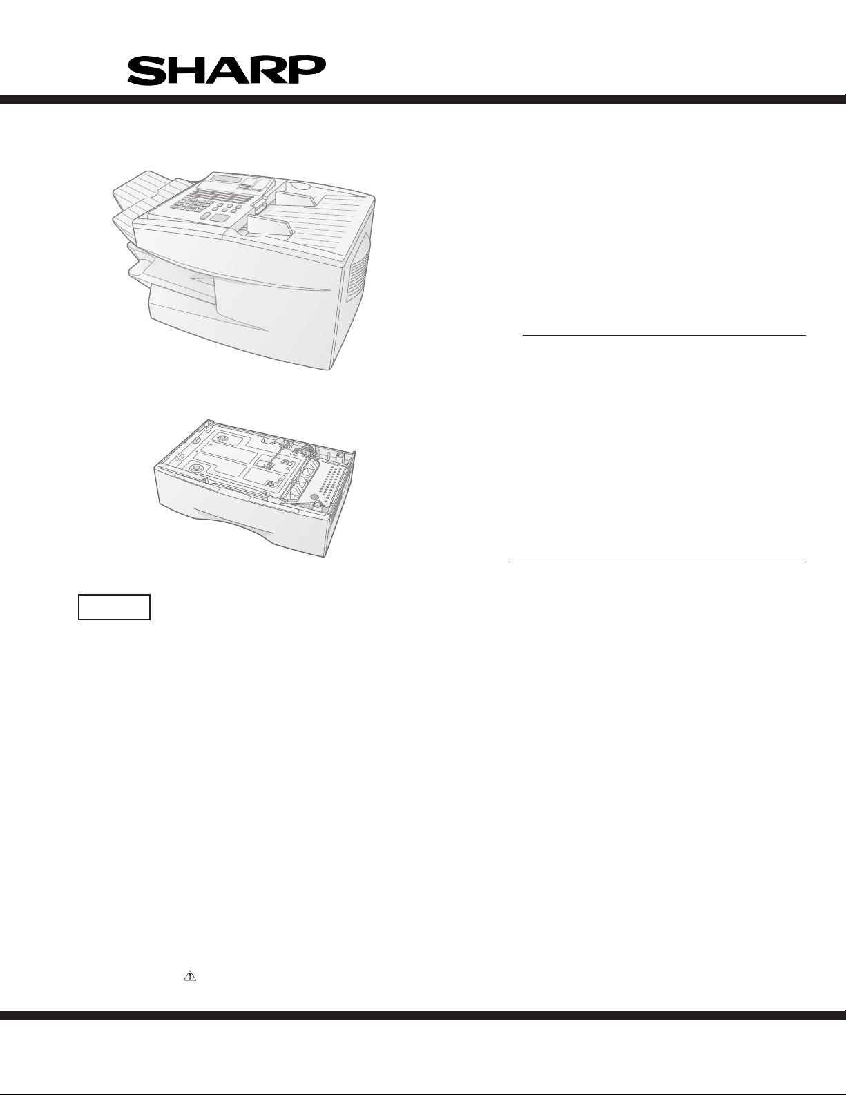
Illustration: FO-4700
FO-4700U
FO-47UC
SERVICE MANUAL
No. 00ZFO4700USME
FA CSIMILE
MODEL FO-4700
OPTION:PAPER CASSETTE
MODEL FO-47UC
Illustration: FO-47UC
CAUTION
This laser printer is a class 1 laser product that complies with 21CFR 1040.10 and 1040.11 of the CDRH standard. This means that
this machine does not produce a hazardous laser radiation. The use of controls, adjustments or performance of procedures other
than those specified herein may result in hazardous radiation exposure.
This laser radiation is not a danger to the skin, but when an exact focusing of the laser beam is achieved on the eyes retina, there is
danger of spot damage to the retina.
The following cautions must be observed to avoid exposure of the laser beam to your eyes at the time of servicing.
1) When a problem in the laser optical unit has occurred, the whole optical unit must be exchanged as a unit, not an individual part.
2) Do not look into the machine with the main switch turned on after removing the toner/developer unit and drum cartridge.
3) Do not look into the laser beam exposure slit of the laser optical unit with the connector connected when removing and installing
the optical system.
4) The cover of Laser Printer Unit contains the safety interlock switch.
Do not defeat the safety interlock by inserting wedges or other items into the switch slot.
Laser Wave Length : 770-810 mm
Laser Pulse Times
Laser Output Power : 0.73 mW
Parts marked with " " is important for maintaining the safety of the set. Be sure to replace these parts with specified ones for maintaining the safety and performance of the set.
: 49.2 µs
SHARP CORPORATION
1 - 1
This document has been published to be used
for after sales service only.
The contents are subject to change without notice.
Page 2

FO-4700U
FO-47UC
CHAPTER 1. GENERAL DESCRIPTION
[1] Specifications . . . . . . . . . . . . . . . . . . . . . . . . . . . . . . . . . . . . . . . . . . . . . . . . . . . . . . . . . . . . . . . . . . 1-1
[2] Operation panel . . . . . . . . . . . . . . . . . . . . . . . . . . . . . . . . . . . . . . . . . . . . . . . . . . . . . . . . . . . . . . . . 1-2
[3] Transmittable documents . . . . . . . . . . . . . . . . . . . . . . . . . . . . . . . . . . . . . . . . . . . . . . . . . . . . . . . . . 1-4
[4] Installation . . . . . . . . . . . . . . . . . . . . . . . . . . . . . . . . . . . . . . . . . . . . . . . . . . . . . . . . . . . . . . . . . . . . 1-5
[5] Quick reference guide . . . . . . . . . . . . . . . . . . . . . . . . . . . . . . . . . . . . . . . . . . . . . . . . . . . . . . . . . . 1-12
CHAPTER 2. ADJUSTMENTS
[1] Adjustments . . . . . . . . . . . . . . . . . . . . . . . . . . . . . . . . . . . . . . . . . . . . . . . . . . . . . . . . . . . . . . . . . . . 2-1
[2] Diagnostics and service soft switches . . . . . . . . . . . . . . . . . . . . . . . . . . . . . . . . . . . . . . . . . . . . . . . 2-2
[3] Troubleshooting . . . . . . . . . . . . . . . . . . . . . . . . . . . . . . . . . . . . . . . . . . . . . . . . . . . . . . . . . . . . . . . 2-35
[4] Error code table . . . . . . . . . . . . . . . . . . . . . . . . . . . . . . . . . . . . . . . . . . . . . . . . . . . . . . . . . . . . . . . 2-36
CHAPTER 3. MECHANICAL DESCRIPTION
[1] Mechanical description . . . . . . . . . . . . . . . . . . . . . . . . . . . . . . . . . . . . . . . . . . . . . . . . . . . . . . . . . . . 3-1
[2] Printer description . . . . . . . . . . . . . . . . . . . . . . . . . . . . . . . . . . . . . . . . . . . . . . . . . . . . . . . . . . . . . . 3-2
[3] Disassembly and assembly procedures . . . . . . . . . . . . . . . . . . . . . . . . . . . . . . . . . . . . . . . . . . . . . . 3-9
CHAPTER 4. DIAGRAMS
[1] Block diagram . . . . . . . . . . . . . . . . . . . . . . . . . . . . . . . . . . . . . . . . . . . . . . . . . . . . . . . . . . . . . . . . . 4-1
[2] Wiring diagram . . . . . . . . . . . . . . . . . . . . . . . . . . . . . . . . . . . . . . . . . . . . . . . . . . . . . . . . . . . . . . . . . 4-2
[3] Point-to-point diagram and connector signal name . . . . . . . . . . . . . . . . . . . . . . . . . . . . . . . . . . . . . 4-3
CONTENTS
CHAPTER 5. CIRCUIT DESCRIPTION
[1] Circuit description . . . . . . . . . . . . . . . . . . . . . . . . . . . . . . . . . . . . . . . . . . . . . . . . . . . . . . . . . . . . . . . 5-1
[2] Circuit description of control PWB . . . . . . . . . . . . . . . . . . . . . . . . . . . . . . . . . . . . . . . . . . . . . . . . . . 5-1
[3] Circuit description of LIU PWB . . . . . . . . . . . . . . . . . . . . . . . . . . . . . . . . . . . . . . . . . . . . . . . . . . . . 5-17
[4] Circuit description of operation PWB . . . . . . . . . . . . . . . . . . . . . . . . . . . . . . . . . . . . . . . . . . . . . . . 5-20
[5] Circuit description of power supply PWB . . . . . . . . . . . . . . . . . . . . . . . . . . . . . . . . . . . . . . . . . . . . 5-20
[6] Circuit description of RS232C I/F PWB (Option:FO-47IF) . . . . . . . . . . . . . . . . . . . . . . . . . . . . . . . 5-21
CHAPTER 6. CIRCUIT SCHEMATICS AND PARTS LAYOUT
[1] Control PWB circuit . . . . . . . . . . . . . . . . . . . . . . . . . . . . . . . . . . . . . . . . . . . . . . . . . . . . . . . . . . . . . 6-1
[2] LIU PWB circuit . . . . . . . . . . . . . . . . . . . . . . . . . . . . . . . . . . . . . . . . . . . . . . . . . . . . . . . . . . . . . . . 6-19
[3] Printer PWB circuit . . . . . . . . . . . . . . . . . . . . . . . . . . . . . . . . . . . . . . . . . . . . . . . . . . . . . . . . . . . . . 6-21
[4] Power supply PWB circuit . . . . . . . . . . . . . . . . . . . . . . . . . . . . . . . . . . . . . . . . . . . . . . . . . . . . . . . 6-25
[5] Operation panel PWB circuit . . . . . . . . . . . . . . . . . . . . . . . . . . . . . . . . . . . . . . . . . . . . . . . . . . . . . 6-27
[6] High voltage PWB circuit . . . . . . . . . . . . . . . . . . . . . . . . . . . . . . . . . . . . . . . . . . . . . . . . . . . . . . . . 6-29
[7] Toner empty PWB circuit . . . . . . . . . . . . . . . . . . . . . . . . . . . . . . . . . . . . . . . . . . . . . . . . . . . . . . . . 6-31
[8] Option:Paper cassette PWB circuit (FO-47UC) . . . . . . . . . . . . . . . . . . . . . . . . . . . . . . . . . . . . . . . 6-32
CHAPTER 7. OPERATION FLOWCHART
[1] Protocol . . . . . . . . . . . . . . . . . . . . . . . . . . . . . . . . . . . . . . . . . . . . . . . . . . . . . . . . . . . . . . . . . . . . . . 7-1
[2] Power on sequence . . . . . . . . . . . . . . . . . . . . . . . . . . . . . . . . . . . . . . . . . . . . . . . . . . . . . . . . . . . . . 7-2
CHAPTER 8. OTHERS
[1] Service Tools . . . . . . . . . . . . . . . . . . . . . . . . . . . . . . . . . . . . . . . . . . . . . . . . . . . . . . . . . . . . . . . . . . 8-1
[2] IC signal name . . . . . . . . . . . . . . . . . . . . . . . . . . . . . . . . . . . . . . . . . . . . . . . . . . . . . . . . . . . . . . . . . 8-7
PARTS GUIDE
1 – 2
Page 3

CHAPTER 1. GENERAL DESCRIPTION
[1] Specifications
FO-4700U
FO-47UC
• GENERAL
Automat ic dialing Rapid Key Dialing: 48 numbers
Speed Dialing: 75 numbers
Memo ry size* 1 MB (approx. 56 pages with ECM off)
Mode m speed 14,400 bps (max.)
Automatic fallback to lower speeds.
Transmission time* Approx. 6 seconds
Toner cartridge yield Initial starter cartridge (included with
(4% page coverage) fax machine): 3700 pages (ave.)
(letter paper)
Replacement cartridge (FO-47ND):
7500 pages (ave.) (letter paper)
Drum car tridge yield Initial starter cartridge (included with
fax machine): 20,000 pages (ave.)
Replacement cartridge (FO-47DR):
20,000 pages (ave.)
Resolution Horizontal: 203 pels/inch (8 pels/mm)
Vertical:
Standard: 98 lines/inch (3.85 lines/mm)
Fine /Halftone:
196 lines/inch (7.7 lines/mm)
Super fine:
391 lines/inch (15.4 lines mm)
Automatic do cument 50 pages max. (20 lb letter paper)
feeder
Paper cap acity 250 sheets (500-sheet
cassette available as option)
Compression scheme MMR, MR, MH, Sharp (H2)
Halftone (grayscale) 64 levels
Applicable telephone line Public switched telephone network
Compatibility ITU-T (CCITT) G3 mode
Printing resolution Horizontal: 406 lines/inch
(16 lines/mm)
Vertical: 391 lines/inch
(15.4 lines/mm)
PC Printing: 600 dpi
Effective Scanning width 8.3" (210 mm) max.
Effectiv e Printing width 8.0" (203 mm) max.
Recepti on mo de s Auto/Manual
Instascan speed 30 ppm (letter paper)
Full Dual Access Yes
Copy function Single/Multi/Sort (99 copies/page)
Power requirements 120 V AC, 60 Hz
Operating temperature 50 - 86°F (10 - 30°C)
Humidity 20 to 85% RH
Power consumption Standby: 10 W
Maximum: 580 W
Dimensions Width: 18.1" (460 mm)
Depth: 15.2" (385 mm)
Height: 10.6" (270 mm)
Weight Approx. 27.8 Ibs.(12.6kg)
* Based on ITU-T (CCITT) Test Chart #1 at standard resolution in Sharp
special mode, excluding time for protocol signals (i.e., ITU-T phase C
time only).
Option
Toner cartridge : FO-47ND
Drum cartridge : FO-47DR
Paper cassette : FO-47UC
PC interface : FO-47IF
Option memory : FO-1MK
Verification stamp : FO-45VS
Input document size Automatic feeding:
Width: 5.8 to 10.1" (148 to 256 mm)
Length: 5.0 to 14.3" (128 to 364 mm)
Manual feeding:
Width: 5.8 to 11.0" (148 to 279 mm)
Length: 5.0 to 17.0" (128 to 432 mm)
Note: This fascismile machine is Year 2000 compliant.
<IMPORTANT PLEASE READ FIRST>
To avoid problems with supplies, please don’t use supplies from other units. Please use new supplies, when supply changes are required.
1 – 1
Page 4
FO-4700U
FO-47UC
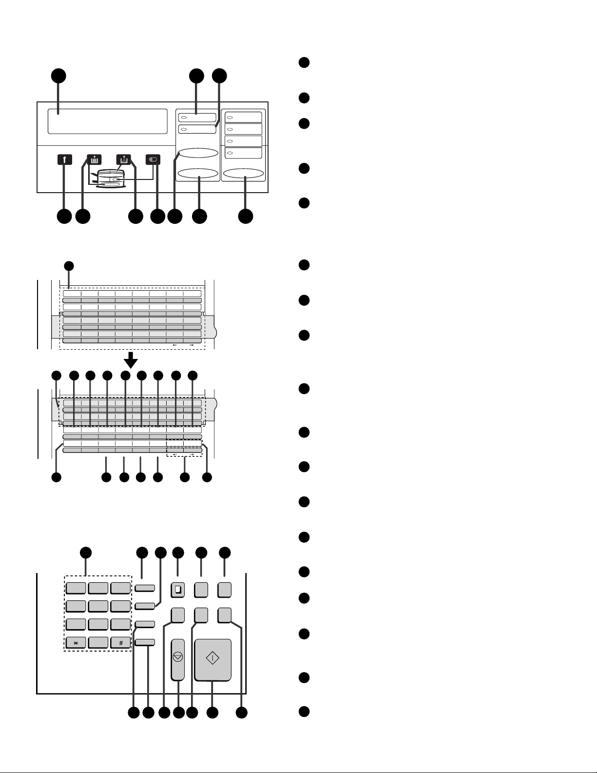
[2] Operation panel
1
4
56
11
01
02
03
04
C
D
11
12
K
L
19
20
S
T
27 28 29 30 31 32
35
36
C
D
43
44
K
L
CONFIDENTIAL
TIMER
S
T
22
21
11
20
A
B
09
10
I
J
17
18
Q
R
25
26
Y
Z
12
13 14 15 16 17 18 19
34
33
A
B
42
41
I
J
PAGE COUNTER
CONTRAST
Q
R
COVER SHEET
Y
Z
7
05
06
E
F
13
14
M
N
21
22
U
V
CLEARSPSHIFTSPACE
37
384639
E
F
45
M
N
RELAY
LIFE
U
V
CLEARSPSHIFTSPACE
24
23
3
2
LINE IN USE
STATUS CHECK
CHANGEOVER
POWER SAVE RESOLUTION
89
07
08
G
H
15
O
23
W
G
47
O
MEM.STATUS
W
DOWN UP
25 26
16
P
24
X
40
H
48
P
SEARCH DIAL
X
Rapid Key
overlay down
STANDARD
FINE
SUPER FINE
HALF TONE
10
Rapid Key
overlay up
Display
1
This displays messages and prompts during operat ion and
programming.
LINE IN USE light
2
This lights when the fax machine is using the telephone line.
STATUS CHECK light
3
This lights when a paper size error or paper jam occurs, or when
the print compartment cover is open. A message will appear in
the display to indicate the problem.
Service indicator
4
This lights when a problem occurs which must be fixed by a
service technician .
Paper out indica t or
5
This lights when the fax machine is out of pa per, or when the
received document tray is not properly installed. If the machine
has a paper cassett e, the indicato r blinks when one of the paper
sources (tray or cassett e) is out of paper , and l ights steadily
when all sources are out of paper.
Toner cartridge indicator
6
This blinks when the toner cartridge nears empty, and lights
steadily when the toner cartridge needs replac ement .
Drum cartri dge in di cato r
7
This blinks when the drum cartridge nears the end of its life, and
lights steadily when the drum cartridge needs replacement.
CHANGEOVER key
8
Two types of infor mation appear in the display: prompts related
to operations you are performing, and information about how
the fax is using the telephone line (transmitting, receiving, etc.).
Press this key to switc h between the two types of information.
POWER SAVE key
9
Press this key to turn on Power Save Mode, or set the Power
Save Mode timer if TIMER has been selected with Option
Setting 31 (Power Save Type).
RESOLUTION key
10
Press this key to adjust the resolution before sending or copying
a document.
Rapid Dial Keys
11
Press one of these keys to dial a fax number automatically.
(Note that you must attach the Rapid Key labels.)
27 28 29 30 31 32
COPY
ABC
DEF
123
GHI
JKL MNO
456
PRS
TUV
WXYZ
789
OPER
0
FUNCTION
SPEED DIAL
REDIAL
SPEAKER
DOCUMENT DUPLEX SCAN
PRIORITY
BROADCAST
STOP START
REPORT
CONTRAST key
12
Press this key to adjust the contrast before send ing or copying
a document.
PAGE COUNTER key
13
Press this key to include a slash and the total number of pages
after each page number on the pages of a transmitted document.
CONFIDENTIAL key
14
Press this key to send or print out a confidential document.
TIMER key
15
Press this key to set an operation to be performed automatically
at a later time.
RELAY key
16
Press this key to send a document to another Sharp fax machine and have that machine in turn rel ay the docu ment to one or
more end receiving machines.
LIFE key
17
Press this key , f ollowed by 1, to check the total number of pages
printed by the fax machine.
MEM. STATUS key
39383736353433
18
Press this key to check the status of documents wait ing in memory for transmission.
1 – 2
Page 5

SEARCH DIAL key
19
Press this key to search through your auto dial fax numbers by
name.
COVER SHEET key
20
Press this key to include a cover sheet when sending a fax.
SPACE key
21
Press this key to enter a space when programming a name.
SHIFT key
22
Press this key to switch between upper and lower case letters
when programming a name.
SP key
23
Press this key to enter a symbol when programming a name.
CLEAR key
24
Press this key to clear a mistake when programming a name or
fax number.
Arrow keys
25
Press these keys to move the cursor forward or backward when
programming a name or fax number.
UP and DOWN keys
26
Press these keys to adjust the volume of the speaker when the
SPEAKER key has been pressed, or the volume of the ring er a t
all other times.
FO-4700U
FO-47UC
Dial keypad (numeric keys)
27
Use these keys to dial and program fax numbers.
FUNCTION key
28
Press this key to select various special func tions.
SPEED DIAL key
29
Press this key to dial a Speed Dial number.
COPY key
30
Press this key to make a copy of a document.
DOCUMENT key
31
Press this key to transmit a document without reading it first
into memory.
DUPLEX SCAN key
32
Press this key to transmit or copy a two-sided document.
REDIAL key
33
Press this key to automatically redial the la st number dialed.
SPEAKER key
34
Press this key whe n transmitting a document by Normal Dialling
to listen to the line and verify the response of the receiving fax
machine.
BROADCAST key
35
Press this key to send a document to a group of r eceiving fax
machines.
STOP key
36
Press this key to cancel an operation before it is complete d.
PRIORITY key
37
Press this key when you need to transmit a document ahead of
other documents waiting in memory for transmission.
ST A RT key
38
Press this key to begin transmission when using Speed Dialling,
Direct Keypad Dialling, or Normal Dialling.
REPORT key
39
Press this key to print out a report on the most recently completed transmission or reception.
1 – 3
Page 6
FO-4700U
(
)
[
]
[
]
FO-47UC
[3] T ransmittab le documents
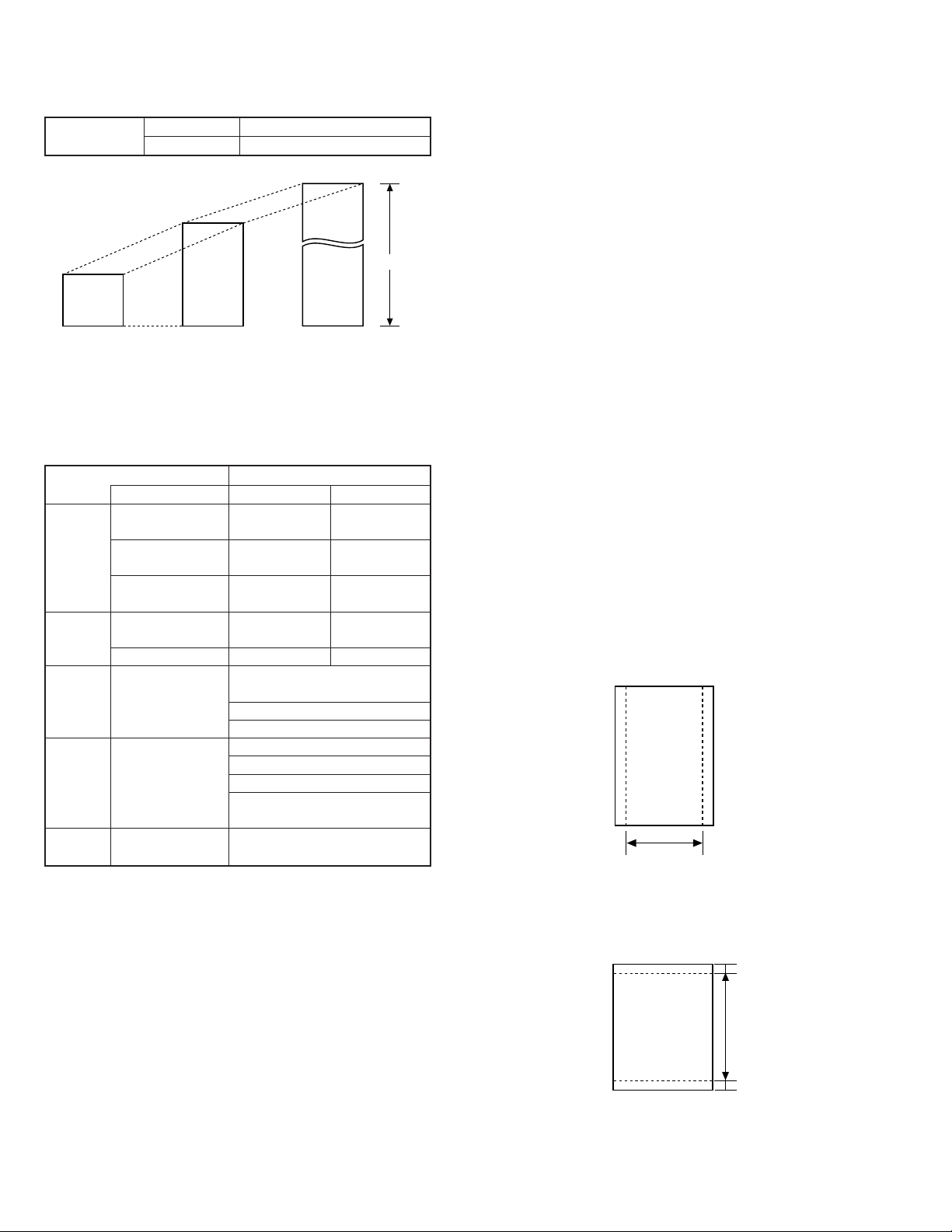
1. Document Sizes
Normal size
(Min.)
128 mm
148 mm 256 mm
* With special sizes, only one sheet can be fed into the machine at a
time. Insert next page into feeder as current page is being scanned.
2. Paper Thickness & Weight
Weight Japanese indication 45kg paper 70kg paper
indication Size 4 × 6
Metric system 52g/m
indication
American indication 14 LB 20 LB
LB system indication
Thickness Metric system 0.06mm 0.1mm
indication indication
Inch system indication 0.0024
Document Document size (148mm × 128mm) ~
size Range W letter (279mm × 432mm)
Number of Document size B6 ~ Letter/A4 size 50 sheets
ADF sheets
Paper Kind Paper of fine quality/bond paper/
quality Kent paper
Weight B4 size/Legal 20 sheets
3. Document Types
• Normal paper
Documents handwritten in pencil (No. 2 lead or softer), fountain pen,
ball point pen, or felt-tipped pen can be transmitted.
Documents of normal contrast duplicated by a copying machine can
also be transmitted.
• Diazo copy (blueprint)
Diazo copy documents of a normal contrast may be transmitted.
• Carbon copy
A carbon copy may be transmitted if its contrast is normal.
width 5.8" – 10.1" (148 – 256 mm)
length 5.0" – 14.3" (128 – 364 mm)
(Max.)
80g/m
0.0035
432 mm
2
"
(Max.)
Normal size
Indication Lower Limit Upper Limit
364 mm
279 mm
Special size
Product specifications
2
"
A4 (210mm × 297mm)
Letter (216mm × 279mm)
W letter size 1 sheet
90 kg (104g/m2) or more
135 kg (157g/m2) or less1 sheet
4. Cautions on Transmitting Documents
• Documents written in yellow, greenish yello w , or light b lue ink cannot
be transmitted.
• Ink, glue, and correcting fluid on documents must be dry before the
documents can be transmitted.
• All clips, staples and pins must be removed from documents before
transmission.
• Patched (taped) documents should be copied first on a copier and
then the copies used for transmission.
• All documents should be fanned before insertion into the feeder to
prevent possible double feeds.
5. Automatic Document Feeder Capacity
Number of pages that can be placed into the feeder at anytime is as
follows:
Normal size: max. 50 sheets (14 lbs - 20 lbs)
Special size: single sheet only (manual feed)
NOTES: • If you need to send or copy more 50 pages, place the ad-
ditional pages and carefully in the feeder just before the
last page is scanned. Do not try to force them in, as this
may cause double-feeding or jamming.
• If your document consists of several large or thick pages
which must be loaded one at a time, insert each page into
the feeder as the previous page is being scanned. Insert
gently to prevent doublefeeding.
6. Readable Width & Length
The readable width and length of a document are slightly smaller than
the actual document size.
Note that characters or graphics outside the effective document scanning range will not be read.
• Readable width
8.3" (210 mm) max.
Readable width
• Readable length
This is the length of the document sent minus 0.16" (4 mm) from the top
and bottom edges.
0.16"(4mm)
Readable length
4mm
0.16"
1 – 4
Page 7
FO-4700U
3
FO-47UC
[4] Installation
1. Site selection
T ake the f ollowing points into consideration when selecting a site f or this
model.
ENVIRONMENT
• The machine must be installed on a level surface.
• Keep the machine away from air conditioners, heaters, direct sun-
light, and dust.
• Provide easy access to the front, back, and sides of the machine. In
particular, keep the area in front of the machine clear, or the original
document may jam as it comes out after scanning.
• The temperature should be between 10° and 35°C (41° and 95°F).
• The humidity should be between 30% and 85% (without condensa-
tion).
ELECTRICITY
AC 120 V, 60 Hz, grounded (3-prong) AC outlet is required.
Caution!
• Connection to a power source other than that specified will cause
damage to the equipment and is not covered under the warranty.
• If your area experiences a high incidence of lightning or power surges,
we recommend that you install a surge protector for the power and
telephone lines. Surge protectors can be purchased at most telephone
speciality stores
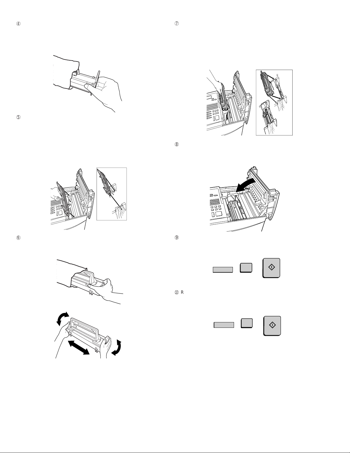
2. Installing the printer cartridges (Toner
cartridge: FO-47ND/Drum cartridge: FO-47DR)
Follow the steps below to install or replace the toner and drum cartr idges.
• The ini tial star ter toner car tridge inc luded with th e fax machine can
print about 3700 letter-size pages (4% coverage of e ach page).
• The replacement toner cartridge (FO-47ND) can print about 7500
letter-size pages.
• The drum cartridge (FO-47DR) can print about 20,000 letter-size
pages.
1
Press the green release and open the pr int compartment cover .
• Caution! The fusing unit inside the print c om partment becomes
very hot during operation. Be careful not to touch the inside of
the compartment.
TELEPHONE JACK
A standard RC11C telephone jack must be located near the machine.
This is the telephone jack commonly used in most homes and offices.
• Plugging the fax machine into a jac k which is not an RC11C jack may
result in damage to the machine or your telephone system. If you do
not know what kind of jack you have, or need to have one installed,
contact the telephone company.
If the machine is moved from a cold to a warm place...
If the machine is moved from a cold to a warm place, it is possible that
the reading glass may fog up, preventing proper scanning of documents
for transmission. To remove the f og, turn on the power and wait appro ximately 2 hours before using the machine.
2
If you are replacing the toner cartridge, remove the old cartridge
and dispose of it according to local regulat ions. Go directly to Step
6 if you are only replac ing the toner cartridge and not the drum car tridge.
• If you are replacing the drum cartridge but not the toner cartri dge, remove the toner cartridge and place it on a sheet of paper.
If you are replacing the drum cartridge, remove the old cartridge
and dispose of it according to local regulations.
1 – 5
Page 8
FO-4700U
4
5
6
7
8
9
F
FO-47UC
Remove the new drum car tr idge from its packaging.
• Caution! Excessive exposure to l ight will damage the drum
cartridge. Install the cartridge promptly after removing it from its
packaging.
Hold the toner cartridge by the handle and lower it into the pr int
compartment. Make sure that the four pins (two on each si de) fi t
into the grooves on the sides of the compartment.
• Insert the cartridge by aligning the colored “2” labels on the
cartridge and the side of the compartment.
• Make sure the toner cartridge clicks into place.
Blue
Green
Insert the drum cartridge into the print c ompartment, aligning the
guides on the ca rtridge with the grooves on the sides of the compa rtment.
• Insert the cartridge by aligning the colored “1” labels on the
cartridge and the sides of the compartment.
• Make sure the drum cartridge is inserted in as far as it will go.
Blue
Green
If you are installing a new toner cartridge, rem ove the new toner
cartridge from its packaging. Shake as indicate d by the arrows to
distribute the toner evenly within the cartridge.
Close the print compartment cover.
• Press down on the dot markings at the left edge to make sure
the cover is completely closed.
Reset the toner counter by pressing the LIFE key (flip up the Rapi-
d Key overlay), 2, and the START key.
START
LIFE
V
2
Reset the drum counter by pressing the LIFE key (flip up the
Rapid Key overlay), 3, and the START key.
START
LIFE
V
When to replace the toner cartridge
When the toner cartridge nears empty (about 100 pages can still be
printed), the toner cartridge indica tor on the operation panel will blink.
When the toner cartridge is empty, the toner cartridge indicator will
light steadily and REPLACE TONER will appear in the display.
Printing will no longer be possible. Use the following replacement
toner cartridge :
Sharp FO-47ND toner cartridge
When to replace the drum cartridge
When the drum cartridge nears the end of its life, the drum cartridge
indicator on the operation panel will blink. When the drum cartridge
life is over, the dr um cartr idge indi cator wil l light ste adily and DR UM
LIFE OVER will appear in t he displ ay. Use the following replacement
drum cartridge:
Sharp FO-47DR drum cartridge
3
1 – 6
Page 9
1
2
3. Assembly and connections
Points to keep in mind when setting up
• Do not place the machine in direct sunlight.
• Do not plac e the machine near heaters or air conditioners.
• Keep dust away from the machine.
• Install the machine on a lev el surface.
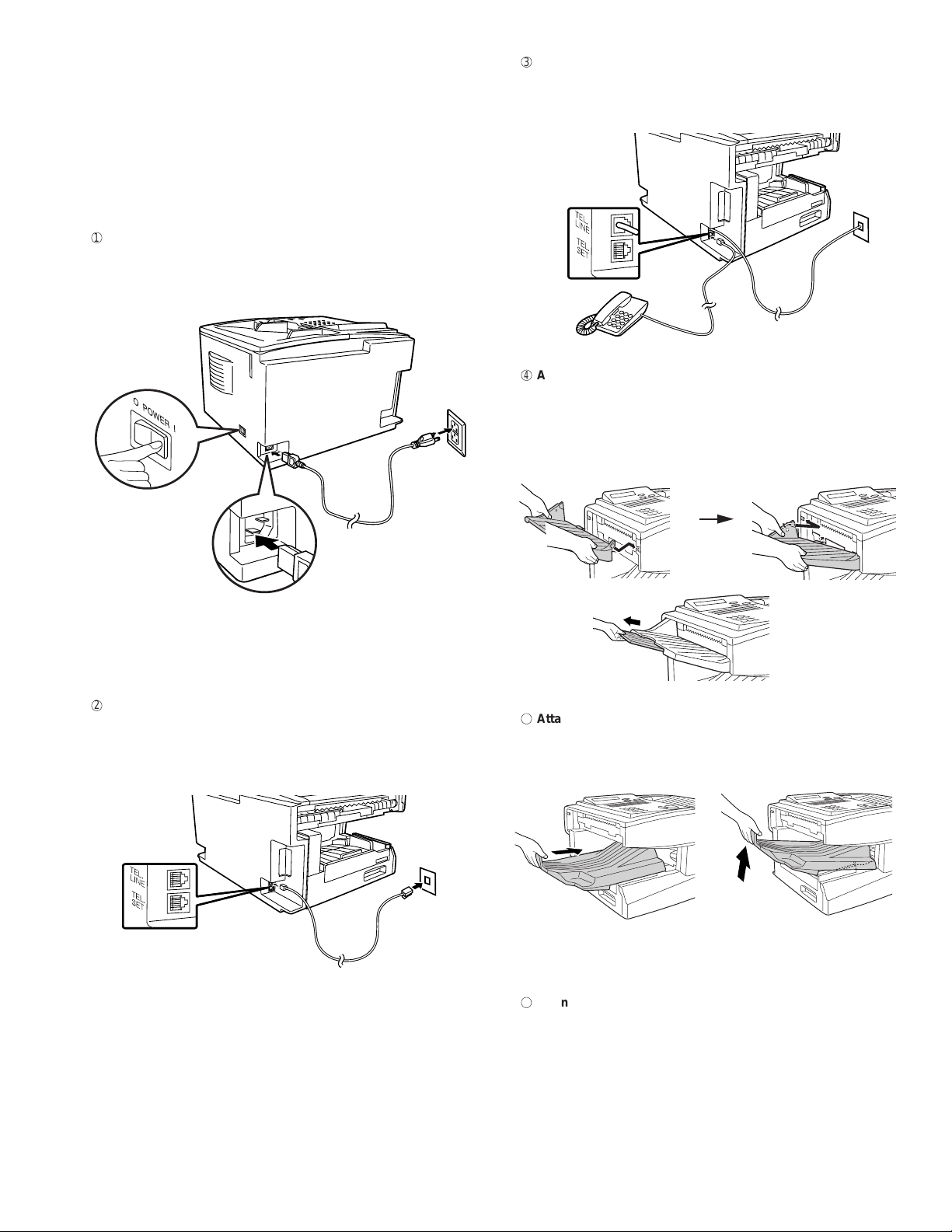
Connecting the power cord
Connect the female end of the power cord to the fax machine as
shown. Insert the male end into a 120 V, 60 Hz, grounded (3-prong)
AC outlet.
FO-4700U
FO-47UC
3 Connecting a telephone (optional)
If desired, you can connect a telephone to the TEL. SET jack
on the back of the machine.
Attaching the document OUT tray
4
Insert the protrusion on the right side of the machin e into the
hole in the right side of the document OUT tray as shown, the n
bend the tray slightly and insert so that the protrusion on the left
side of the machine goes into the hole on the left side of the
document OUT tray.
Press the power
switch to turn on
the power.
Note: If your area experiences a high incidence of lightning or power
surges, we recommend that you install surge protectors for the power
and telephone lines. Sur ge pr otecto rs can be pur ch ased at mos t te lephone specialty stores.
Connecting the telephone line cord
Insert one end of the line cor d into the jack on the back of th e mac hine marked TEL. LINE. Insert the other end into a standard
(RJ11C) single-line wall telephone jack.
Pull out the tray
extension.
5 Attaching the received document tray
Slide the received document tray into the machine as
shown. When it stops, lift the end slightly and push in so
that the tray locks into place.
Note: The fax machine is set for touch-tone dialing. If you are on a
pulse dial (rota ry) line, you must s et t he fa x mac hi ne for pulse dialing
by changing Option Setti ng 22.
Important! The received document tray must be attached for
the fax machine to operate properly.
6
Connection to a computer (Option : FO-47IF)
Note: This function is available as an option. If you wish to use
it, consult your dealer to have the P C interface board installed.
If desired, you can connect the fax machine to the parallel port of
any compatible computer. Once you have installed the provided
printer software in your computer, you will be able to use the fax
machine as a laser printer for your computer.
Important! Use only the provided IEEE P1284 parallel cable to
connect the fax machine to your computer.
1 – 7
Page 10
FO-4700U
7
FO-47UC
1)
Make sure your computer and the fax machine are both turned of f.
POWER
Turn
off
2)
Connect one end of the cable to the port on the fax machine.
Snap the clips on each side of the port onto the cable connector to
secure it.
3)
Connect the other e nd of the cable to the parallel port on the back
of your computer.
4.Loading Printing Paper
Y ou can load up to 250 sheets of letter or legal paper ( max. 20 lbs.)
in the paper tray. You can load up to 500 shee ts of paper in the
paper cassette.
The paper cassette is available as an option.
To have the c ass et te installed, consult your dealer.
Note: To use A4 paper in the paper cassette, you must have a
service technician adjust the cassette.
1
Loading paper in the paper tray
1)
Remove the received document tray.
4)
Press the panel keys as shown to set Option Setting 31(PC
Interface Mode) to ON.
• Before you can use the fax machine as a printer, you must also
install the printer sof tware. To inst al l the software, see the doc umentation that ac companies it.
FUNCTION
4
3
1
1
STOP
STOP
Note: The message PC PRI NT ING wi ll app ear i n the display whe n
the fax machine prints a print job from your computer. While this
message appears, you will no t be a b le to u se t he op eratio n p ane l o f
the fax machine.
Verification Stamp (Option : FO-45VS)
Note: This function is available as an option. Consult your dealer if
you wish to use it.
2)
If you are loading legal paper, grasp the end of the paper tray and
pull it out.
3)
Insert a stack of paper into the tray, print side up.
• If you loaded letter paper, make sure the end of the tray is
pushed in. Otherwise a size error will result.
4)
Replace the received document tray.
• The received document tray must be attached for the fax
machine to operate properly.
When transmitting a document, you can have your fax stamp each
document page as it is scanned. After scanning, you can check to
see if all documents have been stamped to verify that no double feeds
occurred. (A double feed is when two pages are fed through the
scanner at once, which means that one of the pages is not scanned.)
To use this function, have your dealer install the Verification Stamp
option, and then set Option Setting 29 to ON.
1 – 8
Page 11
2
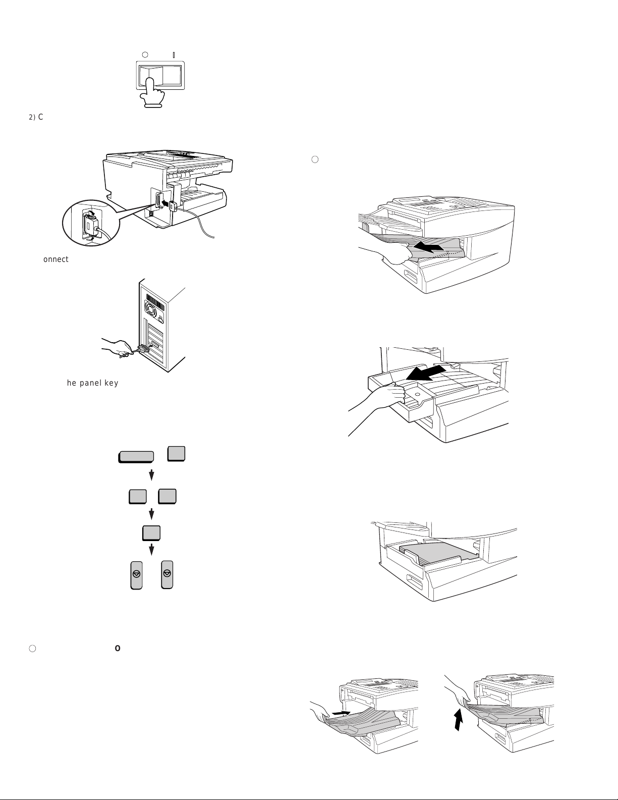
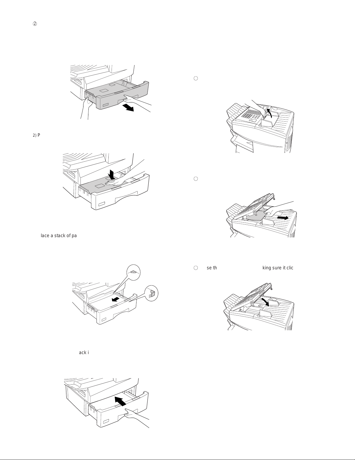
Loading paper in the paper cassette (Option : FO-47UC)
1
2
3
FO-4700U
FO-47UC
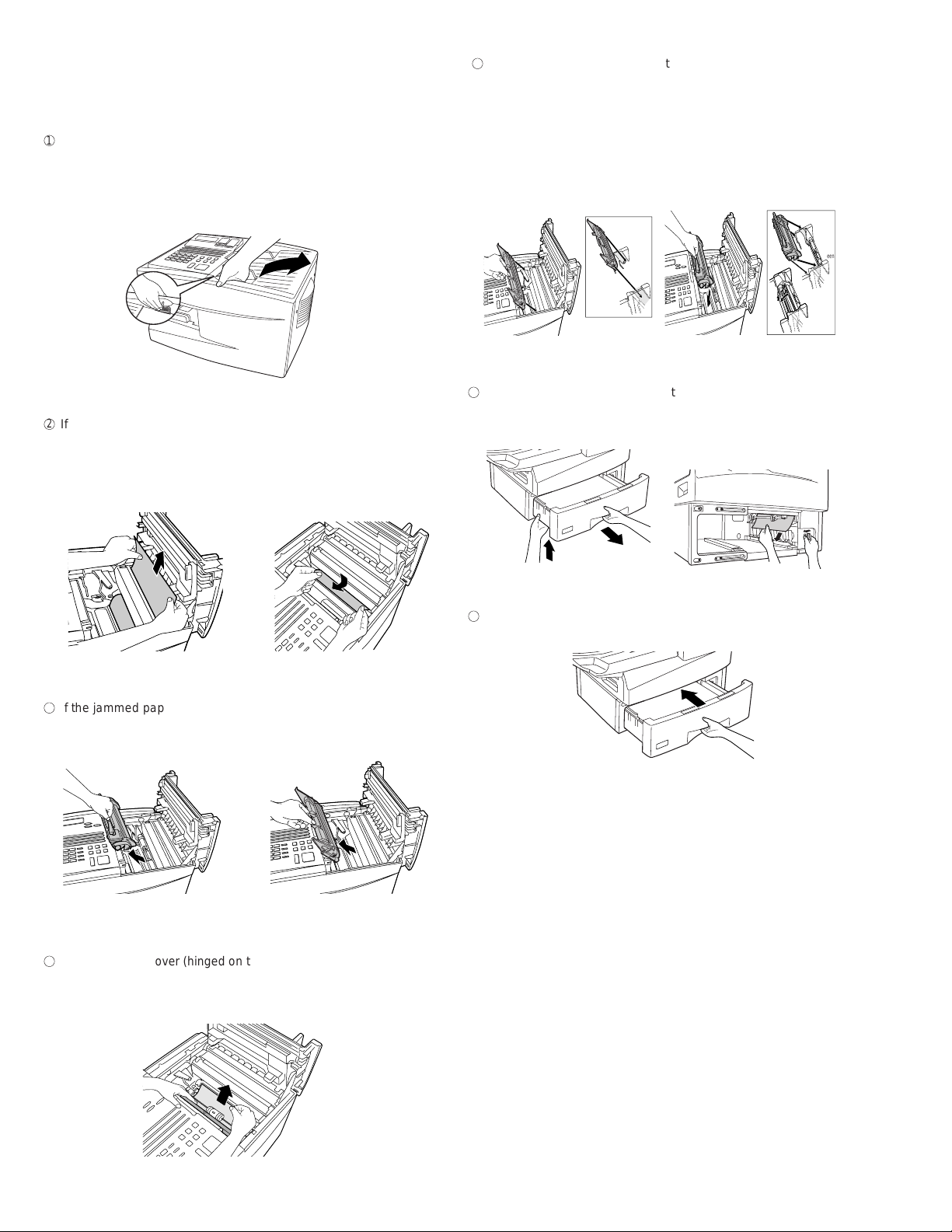
5. Clearing a jammed document
1) Grasp the hand-hold on the cassette and pul l out the cassette until
it stops.
2) Push the pressure plate down until it locks into position.
3) Place a stack of paper in the cassette, print side up.
• Make sure the stack of paper is not higher than the two tabs
on the green paper guide and the met al tab. If it is, remove
some of the paper.
If the original document doesn’t feed properly dur ing transmission or
copying, or REMOVE ORIGINAL(S) appears in the display, first try
pressing the START key. If the document doesn’t feed out, open the
operation panel an d r emove it.
Important! Do not try to remove a document without opening the
operation panel. This may damage the feed er mechanism.
Open the operation panel.
• Squeeze the release marked PANEL RELEASE and pull up.
Remove the document.
Close the operation panel, making sure it clicks into place.
4) Push the cassette back into the machine, making sure it clicks into
place.
1 – 9
Page 12
FO-4700U
1
2
3
4
6
7
FO-47UC
6. Clearing a jammed printing paper
If the printing paper jams, PAPER JAM will appear in the display.
Follow the steps below to clear the jam.
Press the green release and open the print compart ment co ver.
5 Close the black cover . Reinsert the drum cartridge and then the to-
ner cartridge.
• Insert the drum cartridge and toner cartridge by aligni ng t he col ored numbers on the cartridges with their corresponding colored
numbers on the sides of the print compartment.
• Caution! The fusing unit inside the print c om partment becomes
very hot during operation. Be careful not to touch the inside of
the compartment.
If the jammed paper is visible in the print compartment, pull it out.
• Make sure no torn pieces of paper remain in the print compart ment and rollers.
or
If the jammed pa per isn’t visible, remove the toner cartridge and
then the drum cartri dge .
• When finished, close the print compartment cover.
Blue
Blue
Green
Green
If you have a paper cassette and the display still indicates that pa-
per is jammed, open the c a ssette and remove the jammed paper.
Replace the pa per cassette.
Open the black cover (hinged on the left) a t the bottom of the com-
partment. If jammed paper is visible, remove it.
1 – 10
Page 13
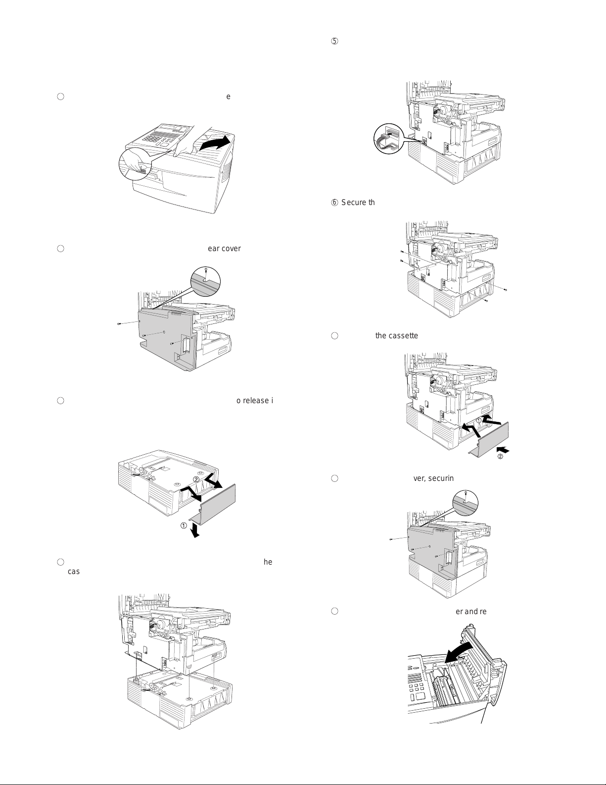
7. Instructions for installing the FO-47UC paper
5
6
7
8
9
1
2
3
4
cassette
Important! B e sur e to turn off the power a nd unplug the power
cord before proceeding.
FO-4700U
FO-47UC
Insert the connector wires into their holder in the edge of the
base plate of the unit, and then insert the co nnector into its socket
on the printed circuit board (the white connector wire should be on
the right).
Remove the document OUT tray (if attached). Press the
green release and open the print compartment cover.
Secure the cassette to the base plate of the unit with the 4 screws
as shown.
Remove the screws (4) that secure the rear cover and then
remove the rear cover.
Reattach the cassette side cover.
Pull down on the bottom edge of the side cover to release it from
its catch, and then rotate the bottom edge up slightly (no more than
30°). Rehold the cover at the sides, bend it in slightly, and remove it.
Reattach the rear cover, securing it with the 4 screws.
Pull out the connector so that it hangs over the edge of the
cassette. Place the unit on the cassette, making sure that the
studs go into the holes.
Close the print compartment cover and reattach the document
OUT tray.
1 – 11
Page 14
FO-4700U
FO-47UC
[5] Quick reference guide
Note: Steps which are optional are enclosed in a dotted frame:
Transmitting documents
Normal Dialing (1)
Normal Dialing (2)
Direct Keypad
Dialing
Rapid Key Dialing
Speed Dialing
Redialing
Load
document
Lift handset
press
Load
document
Load
document
Load
document
START
Load
document
RESOLUTION
or
SPEAKER
RESOLUTION
Wait for
reception tone
Dial (press
numeric keys)
Wait for
reception tone
RESOLUTION
RESOLUTION
RESOLUTION
RESOLUTION
Lift handset
or
SPEAKER
press
Dial (press
numeric keys)
Press Rapid
Key
SPEED DIAL
REDIAL
START
Load
document
START
Dial (press
numeric keys)
Hang up
RESOLUTION
Hang up
START
Enter Speed Dial number
(press numeric keys, - if less
than 3 digits, press
to complete entry)
Wait for
reception tone
START
START
1 – 12
Page 15
FO-4700U
TOP VOID LABEL
FO-47UC
CHAPTER 2. ADJUSTMENTS
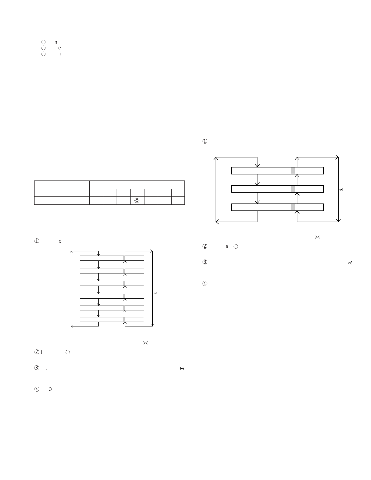
[1] Adjustments
General
Since the following adjustments and settings are provided for this model,
make adjustments and/or setup as necessary.
1. Adjustments
Adjustments of output voltage (FACTORY ONLY)
1. Install the power supply unit in the machine.
2. Set the recording paper and document.
3. When the document is loaded, power is supplied to the output lines.
Confirm that outputs are within the limits below.
Output voltage settings
CONTROL
PWB
CN5
12
POWER SUPPLY
PWB
Output Voltage limits
+5V MAIN 4.845V~5.355V
+5V SUB 4.845V~5.355V
+24V MAIN 23.04V~24.96V
+24V SUB 23.04V~24.96V
Connector CN4
No.
Pin No. CN1
1 11 +5V
2 10 HV C HL
3 9 T VR
4 8 T REM
5 7 T MON
6 6 B MON
7 5 B VR
8 4 C REM
9 3 C MON
10 2 MG
11 1 +24
1
8
1
CN1
12
1
1
CNPW
1
8
CN7
11
CN1
1
CN4
CNPRT
1
1
CN1
PRINTER
–
11
HI VOLTAGE
PWB
PWB
30
30
IC2
Voltage for adjust
IC2
VR1
VD
+ Check point for voltage
+–
Digital multi meter
Fig. 1
Connector CN5
No.
Pin No. CNPW
1 +24V SUB
2MG
3MG
4MG
5 +24V MAIN
6 +24V MAIN
7 +5V SUB
8DG
9DG
10 DG
11 +5V MAIN
12 +5V MAIN
Connector CN1
No.
Pin No. CN7
1 24 MAIN
2MG
3DG
4 5V MAIN
5 HEATER ON
6FAN
7 FAN LOCK
8 H RELAY OFF
ADJUST VOL T A GE LIST
Top V oid Printer Adjust Voltage
Label (mm.) Fig. 2 VR1 Fig. 1
5.5~6.9 4.42V
7.0~8.9 3.87V
9.0~10.9 3.14V
11.0~12.9 2.50V
Fig. 2
13.0~14.9 1.86V
15.0~17.0 1.22V
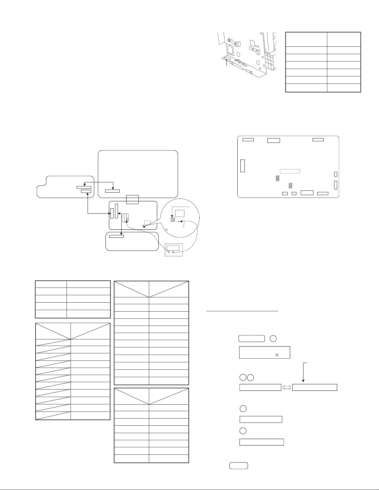
2. IC protectors replacement
ICPs (IC Protectors) are installed to protect the TX motor drive circuit
and verification stamp drive circuit. ICPs protect various ICs and electronic circuits from an overcurrent condition.
The location of ICPs are shown below:
12
1
27 25
CNPW
CNOP
150
130
CNPRT
IC7
F101
CNTXM
CNSTP
11
42
F100
1
1
CNLIU
CONTROL PWB
(BOTTOM SIDE)
CNPN
24
CNCIS
9
CNSP
CNSEN
101
1
2
1
8
Fig. 3
(1) F100 (ICPS10) is installed in order to protect IC’s from and
overcurrent generated in the verification stamp drive circuit. If F100
is open, replace it with a new one.
(2) F101 (ICPS18) is installed in order to protect IC’ s from an overcurrent
generated in the TX motor drive circuit. If F101 is open, replace it
with a new one.
In addition to the replacement of F101 and F100, the factor causing
F101 and F100 to open must also be repaired. If not, F101 and
F100 will open again.
Replacement parts
ICPS10 (Sharp code: VHViCPS10//-1)
ICPS18 (Sharp code: VHViCPS18//-1)
3. Settings
(1) Dial mode selector
OPTION SETTING: DIAL MODE (Soft Switch No. SW2 DATA No. 1)
Use this to set the fax machine to the type of telephone line you are on.
• The factory setting is "TONE".
(step 1) Select "OPTION SETTING".
KEY:
DISPLAY:
(step 2) Select "DIAL MODE".
KEY:
DISPLAY:
(step 3) Select, using "1" or "2".
KEY:
DISPLAY: TONE SELECTED
KEY:
DISPLAY:
(step 4) End, using the "STOP" key.
KEY:
FUNCTION 4
4:OPTIONAL SETTING
ENTER #(01-34, ,#)
2
2
DIAL MODE
1
2
PULSE SELECTED
STOP
Cursor
When initially registering,
the mode shows 1=TONE.
When registering again, the
mode which was registered
formerly is shown.
1=TONE, 2=PULSE
2 – 1
Page 16
FO-4700U
FO-47UC
[2] Diagnostics and service soft switches
1. Operating procedure
Two kinds of diagnoses are supported.
1-1. Fax diagnosis
This diagnosis is concerned with the main body of fax which is used
for production and service support.
Entering the diagnostic mode
FUNC
Press
display will appear.
ROM: FAA0
FAA0
Then press the
and the key or select with the rapid key.
Enter the mode with the
(Diag
•
specifications)
FUNC
02 PRINT AREA
03 ROM & RAM CHECK
04 AUTO FEEDER MODE
05 AGING MODE
06 PANEL CHECK MODE
07 OPTICAL ADJUST MODE
08 PRODUCT CHECK
9 8
START
key. Select the desired item with the
START
key.
9 8 7
START01 SOFT SWITCH MODE
START
START
START
START
START
START
START
ROM:
START
FAA0
7
, and
the
following
key
1-2. Print diagnosis
This diagnosis is concerned with the print which is used for
production and service support.
Entering the diagnostic mode
FUNC
Press
display will appear.
PCU ROM Ver.:
Then press the
key andthe key or select with the rapid key.
Enterthe mode with the key.
(Diag•specifications)
FUNC
01
02
03
08
09
9 8
START
9 8 6
START
START
START
START04
START05
START06
START07
START
START
6
, and
key. Select the desired item with the
START
PCU ROM Ver.:
START
AREA PRINT MODE
CHECK PATTERN 1
CHECK PATTERN 2
CHECK PATTERN 3
PAPER FEED AGING
BIAS ADJUST MODE
LIFE SET MODE
LIFE ALL CLEAR
LIFE ENTRY MODE
the
following
09
10
11
12
13
14
15 CONF. PASSCODE
16
17
18
19
20
START
START
START
START
START
START
START
START
START
START
START
START
SIGNAL SEND MODE
COMM. CHECK MODE
MEMORY CLEAR
FLASH MEMORY
ALL FAX/TEL. ENTRY MODE
DEPT. PASSCODE
PRINT HOLD CODE
MEMORY SET MODE
STAMP AGING
DIAL TEST MODE
COPY DIAG MODE
START10
START11
TOP ADJUST MODE
LIFE CLEAR MODE
Memory clear when power is turned on
Pressing the START and STOP keys, turn on the main power, and the
following message will be displayed.
MEMORY CLEAR
EXECUTE ? 1 = YES , 2 = NO
Here, when 1: YES is selected, the memory will be cleared to be ready
for operation.
If 2: NO is selected, it will continue ready for operation as it is.
2 – 2
Page 17
FO-4700U
FO-47UC
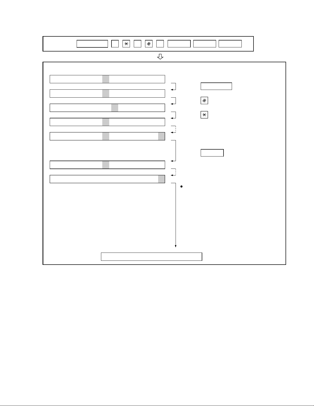
2. Diagnostic items description
2-1. Fax diagnosis
1) Soft switch mode
In this mode, the soft switch are set and the soft switch list is printed.
Soft switch mode screen
S O F T S W I T C H M O D E
S W 0 1 = 0 0 0 0 0 0 0 0
8
Data
1
Switch number selection
1 2 3 4 5 6 7 :DATA No.
Switch
No.
• Press START key for setting of the next soft switch. If the soft
switch number is the final, pressing START key will exit the soft
switch mode.
• Enter two digits of a soft switch number to set the s witch number .
If a switch number of unexisting soft switch is entered, key error
buzzer sounds to reject the input.
S O F T S W I T C H M O D E
S W 0 1 = 0 0 0 0 0 0 0 0
2
Data number selection
The cursor position shows the data to be set.
Pressing # key mov es the cursor to the right. If , howev er, the cursor is
on data number 8, pressing # key shifts the cursor to data number 1
of the next switch number. If the switch number is the final, pressing
# key will exit the soft switch mode.
Pressing key moves the cursor to the left. If, ho we ver , the cursor is
on data number 1, pressing key shifts the cursor to data number 1
of the former switch number. If the switch number is 1, pressing
key will not move the cursor and the error buzzer will sound.
3
Data setting method
Press the FUNCTION key, and the data at the position of the cursor
will be reversed to 0 when it is 1, or to 1 when it is 0. (If the soft s witch
can be changed at the bit (Refer to 6.), the error buzzer will sound
with the process not received.)
4
Outputting method of soft switch list
In the soft switch mode, press the REPORT key, and the soft switch
list will be output.
If the recording paper runs out or is clogged, the key error buzzer will
sound with the process not received.
5
Storage of data
In the following case, the data of the soft switches set will be stored.
E N T E R L A S T D I G I T
S W 1
1 6
S O F T S W I T C H M O D E
S W 1 6 = 0 0 0 1 0 1 1 0
• It is shifted to set the next soft switch by pressing the START
switch.
• It is shifted to set the next soft switch with the [#] key.
• It is shifted to set the last soft switch with the [ ] key.
• It is shifted to set another soft switch by inputting two digits as the
switch number. (When 2 digits are completely input.)
• Output of the soft switch list is started.
6
Inhibition of data change
(This is also applicable for the optional setting.)
In the following case, it is inhibited to change the data with the key
error buzzer.
• Switching ON/OFF of ECM during the use of image memory.
• Switching OFF to ON of the print hold function when the print
hold pass code has not yet been registered.
• Clearing the print hold pass code when print hold function is ON.
• Switching ON/OFF of the print hold function during the use of
memory such as in the case of substitute receiving.
• OFF to ON of telephone billing function which is using the image
memory is used (Note: In the existing set, the telephone billing
code function is specified from OFF to ON when the timer system
communication (including the batch communication) is set.)
Here, the memory is usable when the telephone billing code function is on. It can be set from ON to OFF while the memory is
used. How e v er, if setting is practically changed even once, it can
not be returned from OFF to ON.
• Switching ON/OFF of PC interface function during the use of im-
age memory.
• OFF to ON of department control function during use of image
memory.
(Note: In the existing set, the department control function is set
from OFF to ON when the timer communication (including the
batch sending) or the memory hold is set.)
• ON to OFF of continuous serial polling function when the con-
tinuous serial polling is started.
(Note: In the existing set, "ON to OFF of the continuous serial
polling function when the continuous serial polling is registered"
has been applied, but the conditions are now moderated. However , registration is impossib le to the program of the new continuous serial polling when the continuous serial polling function is
OFF.)
• In addition, change of all soft switches during communication
7
Linked change of data (This is the same even in the optional setting.)
• When the department control function is off, the multi TTI func-
tion and telephone billing code function are turned off.
2) Print area
According to the size of the specified sheet, the effective printing area is
printed.
3) ROM & RAM check
The sum value of ROM, the work and the back-up RAM are checked.
The RS232C interface is also checked. If any error occurs, the buzzer
will inform it. (Ref er to the following table). Finally , the result will be printed.
This diagnosis does not check the flash memory. The flash memory is
checked with the flash memory test.
Number of buzzer sounds Device checked Remarks
1 time <Short sound> ROM Main
2 times <Short sounds> Integrated ROM Main
3 times <Short sounds> SRAM Main
4 times <Short sounds> D-RAM Main
For the short and long sounds, one pattern is as follows.
Main system: 0.5 seconds ON/0.5 seconds OFF
Sub system: 1.00 second ON/0.5 seconds OFF
The execution state of checking is as follows. Moreover, the list of the
check result is output after checking is ended.
Display during check
ROM CPU SRM DRM
• • • •
Display after check
ROM CPU SRM DRM
P P P E
P=PASS E=ERROR
ROM/RAM
check list
output
2 – 3
Page 18
FO-4700U
FO-47UC
4) Auto feeder mode
The auto feed function can be checked by inserting and discharging the
document. (The distance between pages can be displayed dur ing operation of the scanner.)
1
Check of auto feed function
After this mode is activated, set up the document, and press the
ST AR T k ey, and it will be automatically fed. (Bef ore the START key is
pressed, the document sensor alone is activated.) Moreover, the
document size (A4/B4) and sensor information (A4/B4/ORG) are displayed when the document sensor is turned.
04 : AUTO FEEDER MODE
After setup of the document
04 : AUTO FEEDER MODE
B4 (A4 B4 ORG)
Only the sensor which is
activated (fallen down) is displayed.)
The paper sheet size (A4/B4) is
displayed.
2
Display of distance between pages during operation of the scanner
• Soon after this mode is activated, press the FUNCTION key for 5
seconds or more, and the display mode of the distance between
pages will be activated. Then, set up the sending paper and select
the image quality, and then press the START key, and operation
will be started.
Be sure to press the FUNCTION key prior to the START key. If
the FUNCTION key is not pressed but the START ke y is pressed,
it will operate in the same matter as in the existing auto feeder
mode.
If the START key is pressed, the FUNCTION key will be invalid
hereafter. Therefore, the display mode of the distance between
pages and the existing mode can not be changed.
• While the sending paper is read, the image quality key can be
input. STD/FINE/S-FINE modes are usable. However, the same
operation of FINE will be selected if the intermediate tone is set.
• The image quality , the length of the sending page read, the page
distance to the next sending paper and the total of the sending
papers read are shown on the display.
• When the stop key is pressed or 100 sending papers are read,
the content shown on the display will be totally output as the list
after the remaining sending papers are discharged.
5) Aging mode
If any document is set up in the first state (when started), copying will be
executed. If it is not set up, "check pattern 1" of the print diagnosis is
output at the intervals of 1 time/60 minutes. (A total of 10 sheets are
output.)
7) Optical adjust mode
Set documents and press the START key for ordinary copying.
According to key operation, copying can be temporarily stopped.
STOP key: To temporarily stop reading documents.
START key: To start reading documents again.
When any document is not set, print area printing is performed.
8) Product check
The diagnosis is used in the production process.
After shift to the mode, the following operations are sequentially executed. At this time, the sensor of read-error can be checked by feeding
the B4 document. Set up one short document of B4 size.
1
Memory clear (Same as Diagnosis 11)
2
Panel test (Same as Diagnosis 06)
3
Dial test (Same as Diagnosis 24)
4
Document auto feed
5
ROM & RAM test check (Same as the Diagnosis 03)
6
Flash memory test mode (Same as Diagnosis 12)
7
Registration of fixed data
Registration of rapid key No. and other data necessary for produc-
tion.
The registered data are shown in the following table. The chain dial
is not set for any destination.
Rapid FAX Rapid FAX Rapid FAX Rapid FAX
No. No. No. No. No. No. No. No.
01 20 06 25 11 1 21 01
02 21 07 26 12 2 22 02
03 22 08 27 13 3 23 03
04 23 09 28 14 4 24 04
05 24 10 29 15 5 25 05
8
Transmission check (Same as Diagnosis 10)
The soft switches necessary for production are set.
9
Test result print (one sheet)
Memory clear printing
Panel test result printing
ROM & RAM test result printing
F
Print area printing (one sheet)
6) Panel check mode
This is used to check whether each key is normally operated or not.
According to the key input, LCD is display ed. Moreo ver, during e xecution,
the document reading lamp is turned on.
Test results are printed. (The maximum 100 input keys can be printed .)
LED repeats lighting at regular intervals in sequence. (Lighting speed
is specified separately.)
In case of inputting all keys, key input OK is displayed when finishing
the STOP key.
When pressing the NUMERIC key during panel check, output of DTMF
corresponding with the key is started.
When pressing other keys, output is stopped.
2 – 4
Page 19

9) Signal send mode
Rapid key RXX XX : Rapid number
SPEED key SXXX XXX
: Speed key number
After shift to the mode, press the START key, and the signals will be
transmitted in the following sequence.
It can be used to check the modem and so on.
[ 1] No signals
[ 2] 4800BPS (V27ter)
[ 3] 14400BPS (V. 33)
[ 4] 12000BPS (V. 33)
[ 5] 14400BPS (V. 17)
[ 6] 12000BPS (V. 17)
[ 7] 9600BPS (V. 17)
[ 8] 7200BPS (V. 17)
[ 9] 9600BPS (V. 29)
[10] 7200BPS (V. 29)
[11] 4800BPS (V27ter)
[12] 2400BPS (V27ter)
[13] 300BPS (FLAG)
[14] 2100Hz (CED)
[15] 1100Hz (CNG)
10) Comm. check mode
Turn on the line monitor.
1
2
Turn off the COVER SHEET FUNCTION.
3
Set line equivalence at 0 km.
After the check, it is necessary to be sure to return the aforementioned
soft switches into the initial state.
(Clear the memory with the diagnosis.)
11) Memory clear
Clear the back-up memory to initialize the soft switches.
The flash memory will be initialized. Then, the initialized list be output.
12) Flash memory
The flash memory is checked.
The ordinary memories (ROM, SRAM, DRAM) are checked in the ROM
& RAM check process. The write/read test is taken every block to print
the result.
When an error occurs, the following error buzzer will sound.
Number of buzzer sounds Check device
9 times <Short sounds> Flash memory(Option)
During operation of this diagnosis, dual operation is not possible at all.
If this is excessively repeated, it will shorten the life of the flash memory .
13) All FAX/TEL. entry mode
The function is used to simplify the registration of FAX/TEL No. during
aging.
1
The diagnosis mode is activated. If anything is not registered in the
Rapid number 01 or any program or group is not registered, it will
pass the diagnosis without doing anything.
2
The FAX/TEL number (including the substitutive destination) of the
Rapid number 01 is copied to the Rapid numbers 02 thru 48.
3
F AX number of the Rapid number 01 is copied to SPEED key numbers
001 thru 200.
FO-4700U
FO-47UC
4
If any chain dial is not in the Rapid number, the Rapid numbers 02
thru 48 and SPEED key numbers 001 thru 200 are registered in the
group number 01.
If any chain dial is set, the group will be not produced but the chain
dial setting alone of the Rapid number 01 will be reset.
(In all others except the Rapid number 01, the chain dials will be
continuously set as they are.)
(16th and subsequential letters of the destination name registered in the
Rapid number 01 will be discarded.)
14) Dept. passcode
The department passcode list is printed.
15) Conf. passcode
The confidential passcode list is printed.
Differing from printing of one box alone soon after registration, the confidential passcodes of all boxes are printed.
16) Print hold code
The print lockout passcode No. is printed.
17) Memory set mode
The set and dump list of the memory content is output.
• The address (8 digits (P) generally including the bank information is
input, and the data of 2 digits is continuously input.
Inputting is done in the hexadecimal mode. The ten-key is used for 0
thru 9, and the alphabetic keys A (RAPID 01 thru 06) are used for A
thru F.
• During data inputting, the address can be moved forward and back-
ward one byte by one byte with " " and "#". (The address prior to the
address 0 is looped as the maximum address.)
• The V alidity of the address is not chec ked. Accordingly, writing/ read-
ing operations are possible in the address of the memory not assigned, the address of ROM and so on.
(Howev er , as practical, writing is not done, and the data content runs
short each reading.)
Though writing is possible in the flash memory, a little time is required.
It is also necessary to take care that the life of the flash memory is
excessively shortened if much data is written in the flash memory.
Since it may run away depending the written content, take minute
care for the writing address.
• When the REPORT key is input, the memor y dump list is produced
from the displayed address (here, it is limited at the 16-byte boundary address (address with end 0) which does not exceed the specified address and is just in front.). The dump list is output to a maximum of 99 pages. If any data of one page can be repeatedly developed and printed, the list is sufficient. But it is not desired that the
content of plural pages are developed in the memory once and are
then printed. If the ST OP k e y is pressed, it will pass to the diagnosis
after the page which is now being printed is completed printed.
If the address exceeds the maximum address, it will return to the
address 0 and printing will be continued.
18) Stamp aging
Diag mode is left though it doesn’t have this function.
2 – 5
Page 20
FO-4700U
FO-47UC
19) Dial test mode
The mode is used to inspect whether dialing is accurate in two kinds of
dial modes . All data which can be dialed in this mode are automatically
called up in both PB mode and DP mode.
When this mode is activated, the following operations will be automatically executed . Whether the dialed content is right or not is judged with
the external instrument which is connected to the line cable.
1
After shift to the FAX diagnosis mode, press RAPID 24.
(Also switch the display with the [ ] and [#] keys.)
2
Press the START key.
3
Turn on CML, and dial the following in the PB mode.
1, 2, 3, 4, 5, 6, 7, 8, 9, , 0, #
4
Turn off CML 500 mS alone.
5
Dial the following in the DP mode.
1, 5, 9, 0
6
After dialing, turn off CML.
This mode uses the ordinary auto dial. (Accordingly, the signal sending
time and minimum pause are all the same as ordinary.
The measurement result in this mode is completely all the same as in
the ordinary dial mode.
Moreover, the same process as abo ve is also done in the dial test mode
which is executed in the product check mode.
20) Copy diag mode
In order to shorten the process time during production, this mode is
used to automatically switch the copy mode. Three men us are provided.
1. 1Set up two documents. (In case of two documents or more,
there is no problem.
2
Press the START key.
3
Copy 1st document in the fine mode/density A UTO . (One sheet
is printed in the ordinary copy mode.)
4
Copy 2nd (subsequential) document in the intermediate tone
mode/density DARK. (In the ordinary copying mode, one sheet
is printed when the RESOLUTION key is pressed three times.)
When copy test is tried during production or is checked in two modes
(fine and intermediate tones), this mode is provided to reduce the troublesome work which makes the operator stand aside to change the mode.
Accordingly, the fine and inter mediate tones are merely switched, and
the mode is not switched to another mode. (Input of the image quality/
density key is invalid.)
2. Try the copy in the mode fixed at COPY REDUCE 95% and fine
mode/density AUTO. At this time, don’t change the soft key of
COPY REDUCE. (Input of the image quality/density key is invalid.)
3. Continuously try the above items 1 and 2.
2-2. Print diagnosis
Rapid key 01: Area print mode
The effective printing area frame is printed in the specified sheet size.
1
2
3
4
5
6
7
8
9
4mm ± 2
208mm
1. [Full black pattern]
2. [Intermediate tone 2 pattern]
3. [Intermediate tone 1 pattern]
4. [Mesh point pattern]
4mm ± 2.5
4mm
4mm
The left pattern is repeated.
The left pattern is repeated.
The left pattern is repeated.
5. [Longitudinal strip 2 pattern]
Black 2 dot and white 2 dot are repeated in line.
6. [Lateral strip 2 pattern]
Black 2 line and white 2 line are repeated.
7. [Longitudinal strip 1 pattern]
Black 1 dot and white 1 dot are repeated in line.
8. [Lateral strip 1 pattern]
Black 1 line and white 1 line are repeated.
9. [Full White pattern]
Rapid key 02: Check pattern 1
The lateral stripe 2 pattern is printed on one sheet.
(Black 2 line and white 2 line are repeated.)
Rapid key 03: Check pattern 2
The lateral stripe 2 pattern is printed on multiple pages.
Press the STOP key to end the printing.
Rapid key 04: Check pattern 3
The intermediate tone 1 is printed on one sheet.
2 – 6
Page 21
Rapid key 05: Paper feed aging
LI FE1= 00000
LI FE2= 00000
LI FE3= 00000
0
0
0
# key
key
The mode is used for aging related to the printing. In this mode, the
following modes are provided.
1
Blank paper aging mode (ALL WHITE AGING)
2
Whole black print aging mode (ALL BLACK AGING)
3
4% printing aging mode (4% AGING)
After selecting the paper-pass aging mode in the print diagnosis mode,
input the number of each mode above with the ten-key, and the mode
will be executed. The detailed specifications of each mode are described
as follows. Here, the operation in each mode is stopped only when the
STOP key is pressed by the operator or a pr inting-impossible error occurs.
• Blank paper aging mode
In the mode, printing is continued in the whole white (white paper)
printing pattern until the STOP key is pressed by the operator . (In the
printing area)
• Whole black printing aging mode
In the mode, printing is continued in the whole black (whole black)
printing pattern until the STOP key is pressed by the operator . (In the
printing area)
Rapid key 06: Bias adjust mode
The mode is used to adjust the printing density of the printed image. The
image printing density is adjustable in seven steps of 1 to 7.
For details, refer to the following table. (For selection, use the keys 1
thru 7.)
FO-4700U
FO-47UC
Rapid key 08: Life all clear
The mode is used to clear the life counter of the printer of the counter
of the auto feeder.
Note: The counter shows the operational state of the printer (e.g. ho w
many sheets have been printed since start of use?). The ordinary memory does not reset the counter. Accordingly, it is necessary to reset this counter in addition to the ordinary memory
clear if the content in the memory on the control PWB is broken
because of PWB repair, etc. (In the production stage, it is necessary to execute this in the last process.)
Rapid key 09: Life entry mode
(For Serviceman temporary counter)
The mode is used to set a desired value for the judgment value (alarm
judgment counter value) of the general purpose life counters 1 thru 3 of
the printer. If the life of a consumable part (developer,imprinter, etc) is
set, the model which has the error display and RMS function will inform
RMS when the counter reaches the set value. For setting, proceed with
the following procedure.
1
When the life counter setting mode is selected, the following will be
displayed.
Image printing density Thin ←→Thick
12345 67
Default value
Rapid key 07: Life set mode
The mode is used to set the life counter of the printer and the counter of
the auto feeder at desired values. For setting, proceed with the following
procedure.
1
When the life counter setting mode is selected, the following will be is
displayed.
= 00123
DRUM
LIFE
LIFE
IFE1
L
LIFE2
LIFE3
0
= 00123
0
= 00123
0
= 00123
0
= 00123
0
0
key
MACHINE
# key
FEEDER LI FE= 00123
The cursor blinks at the top data.
Five counters can be selected with the "#" and " " keys.
2
In the state 1, input a desired setting number of 6 digits with the ten-
key.
3
After input of 6 digits, shift to another counter with the "#" and " "
keys as necessary. When all necessary counters are completely input, press the START key.
4
"STORED" will be display ed with the set values stored into the memory .
For checking, retry this mode.
Note:
This counter indicates the printer use conditions such as numbers of
printed pages from the beginning of use. In the normal memory clear
condition, the counter will not be reset.
In conditions including damaged memory contents caused by repairing
the panel, this counter should be reset or cleared in addition to the ordinary memory clear.
The cursor blinks at the top data.
Three counters can be selected with the "#" and " " keys.
2
In the state 1 , input a desired setting number of 6 digits with the tenkey .
3
After input of 6 digits, shift to another counter with the "#" and " "
keys as necessary. When all necessary counters are completely input, press the START key.
4
"STORED" will be displayed with the set values stored into the
memory. For checking, retry this mode.
Note: The counter shows the operational state of the printer (how many
sheets have been printed since start of use? and others). The
ordinary memory does not reset the counter. Accordingly, it is
necessary to reset the counter or do the clear process in addition to the ordinary memory clear if the content in the memory
on the control PWB is broken because of PWB repair, etc. (In
the production stage, it is necessary to execute this in the last
process.)
Rapid key 10: Top adjust mode
As the method to adjust the top margin for printing, adjust top margin
adjusting VR on the PWB. If this mode is used at this time, adjustment is
possible without the printing test every time when VR is turned.
For the practical use, determine the adjusting value on the basis of the
old data, and adjust to the determined value in this mode. Then, chec k it
with the printing test.
2 – 7
Page 22
FO-4700U
FO-47UC
Rapid key 11: Life clear mode
The mode is used to respectively clear the life counter of the printer and
the counter of the auto feeder. For setting, proceed with the following
procedure.
1
When the life counter clearing mode is selected, the following will be
is displayed.
Seven counters can be selected with the "#" and " " keys.
MACHINE
DRUM
# key
FEEDER L I FE LEAR
TONER L I FE LEAR
2
In the state 1, input the CLEAR key, and the counter will be respec-
LIFE
LIFE
L
IFE1
LIFE2
LIFE3
LEAR
C
LEAR
C
LEAR
C
LEAR
C
LEAR
C
C
C
tively cleared.
3
After one clear, move the cursor to another counter with the "#" and
" " keys as necessary, and then press the CLEAR key. When the
necessary counters are completely cleared, press the STOP key.
key
2 – 8
Page 23
3. How to make soft switch setting
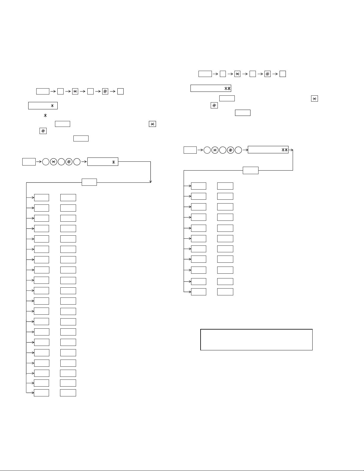
To enter the soft switch mode, make the following key entries in sequence.
FO-4700U
FO-47UC
Press
FUNCTION
9 8 7 START 0 1START
S F T S W 1 = 0 0 0 0 0 0 0 0
S F T S W 1 = 1 0 0 0 0 0 0 0
S F T S W 1 = 1 0 0 0 0 0 0 0
S F T S W 1 = 1 0 0 0 0 0 0 0
S F T S W 1 = 1 0 0 0 0 0 0 0
S F T S W 2 = 0 0 0 0 0 0 0 0
S F T S W 99 = 0 0 0 0 0 0 0 0
Press FUNCTION key.
Press key.
Press key.
Bit1 - 8 are set.
Press key during setting.
START
Soft SW2 - 99 are set.
To finish the settings halfway between
SW 1 and SW99, press the STOP key.
In this case, the setting being done to
the SW No. on display will be nullified
while settings done to the preceding
SW Nos. remain in effect.
The soft switch mode is terminated.
2 – 9
Page 24
FO-4700U
FO-47UC
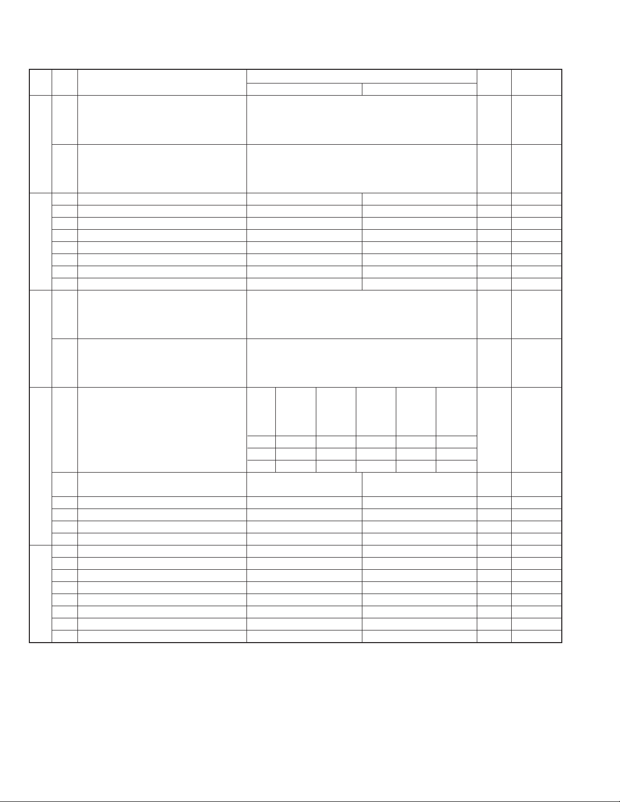
4. Soft switch description
• Soft switch
DA TA
SW
NO.
NO.
1 Recall interval Binary input 8421 0 OPTION
2 No. = 1234(Data No.) 1 Set to 1~15
3 EX 0101 0
SW1
SW2
SW3
SW4 3 No. 3 1 00001
SW5
4 eg. Recall interval is set to 5 min. 1
5 Recall attempts Binary input 8421 0 OPTION
6 No. = 5678(Data No.) 0 Set to 0~14
7 EX 0010 1
8 eg. Recall attempt times is set to 2 times. 0
1 Dial mode PULSE TONE 0
2 Receive mode AUTO MANUAL 1
3 ECM mode Off On 0 OPTION
4 Reserved 0
5 Polling security On Off 1 OPTION
6 Auto cover sheet No Yes 1 OPTION
7 JUNK-FAX function in manual reception Yes No 0
8 JUNK-FAX function Yes No 0 OPTION
1 Number of rings for auto-receive Binary input 8421 0 OPTION
2 (0: No ring receive) No. = 1234(Data No.) 0 Set to 0~9
3 EX 0001 0
4 eg. Number of rings for auto receive is set to 1 time. 1
5 Switch to auto-receive from manual receive Binary input 8421 0 OPTION
6 (0: No switch) No. = 5678(Data No.) 0 Set to 0~9
7 EX 0000 0
8 eg. Switch to auto receive is set to disable. 0
Communication results printout Printed at Printed at Printed at
1 No. 1 0 00110
2 No. 2 0 01010
4 Image addition function to the communication On Off 1 OPTION
result table (for memory transmission only)
5 Reserved 0
6 TEL billing code function On Off 0 OPTION
7 Billing code position Before After 1 OPTION
8 Multi-TTI feature On Off 0 OPTION
1 Time display format 24 hours 12 hours-AM/PM 0
2 Date display format Month-Day-Year Day-Month-Year 1
3 Header print Off On 0
4 Footer print On Off 0
5 Relay data output No Yes 0
6 Substitute reception Off On 0
7 Substitute reception conditions Reception disable without TSI Reception enable without TSI 0
8 CSI transmission Off On 0
ITEM
error only
Switch setting and function
1
error/timer/
memory sion mode
only only
transmis- every time
0
Not printed
Printed OPTION
Initial
setting
Remarks
2 – 10
Page 25
FO-4700U
FO-47UC
DATA
SW
NO.
NO.
1 Reserved 0
2 Reserved 0
3 MMR On Off 1
4 MR On Off 1
SW6 Modem speed V.33 V.17 V. 29 V. 27ter
5 No. 5 0 0 1 1 1 1 0 0 0 0 1
6 No. 6 1 1 0 0 0 0 0 0 0 0 0
7 No. 7 0 1 0 1 0 1 0 1 1 0 0
8 No. 8 0 0 0 0 1 1 1 1 0 0 0
Reception speed fixed NO V. 17- V. 29- V. 27ter-
1 No. 1 0 1 0 1 0
2 No. 2 0 1 1 0 0
3 DIS receive acknowledge during Twice Once in NSF reception, twice 0 Effective to
G3 transmission in DIS reception international
SW7 comm.
4 Non-modulated carrier in V.29 On Off 0
transmission mode
5 CNG send in manual transmission On Off 1
6 Protocol monitor On Off 0
7 Line monitor On Off 0
8 Max. length for TX/RX/Copy TX: unlimited, RX: unlimited TX/Copy: 1.0m, RX: 1.5m 0
Compromised equalizer 0Km 1.8Km 3.6Km 7.2Km Valid when
1 No. 1 0 0 1 1 0 transmitting
2 No. 2 0 1 0 1 1
3 H2 mode No Yes 0
SW8
4 Signal transmission level Binary input 16 8 4 2 1 0
5 No. = 45678 (Data No.) 1
6 EX 01010 0
7 eg. Signal transmission level is set to -10dBm 1
8 0
ITEM
Switch setting and function
1
14400 12000 14400 12000
0
9600 7200 9600 7200 4800 2400
14400BPS 9600BPS 4800BPS
Initial
setting
Remarks
When 14400BPS
MODEM used,
setting to
14400BPS is
ignored.
2 – 11
Page 26
FO-4700U
FO-47UC
SW
DA TA
NO.
NO.
CED tone signal interval 75ms 500ms 750ms 1000ms
1 No. 1 0 0 1 1 0
2 No. 2 0 1 0 1 0
3 Equalization freeze On Off 0
SW9 4 Equalization freeze conditions All 7200bps 0
5 CED detection time 500ms 1000ms 0
Alarm buzzer 3sec 1sec No BEEP No BEEP
6 No. 5 0 0 1 1 0
7 No. 6 0 1 0 1 0
8 Action when RTN received Not Error Error 0
1 Memory retransmission times Binary input 8421 1 OPTION
2 No. = 1234(Data No.) 0
3 EX 1010 1
SW10
SW11
SW12
SW13
SW14
4 eg. Retransmission time set to 10 times. 0
5 Memory retransmission interval Binary input 8421 0 OPTION
6 No. = 5678(Data No.) 0
7 EX 0010 1
8 0
1 Reserved 1
2 Reserved 1
3 Reserved 1
4 Reserved 0
5 Reserved 1
6 Reserved 1
7 Reserved 1
8 Reserved 0
1 Reserved 0
2 Reserved 0
3 Reserved 0
EOL detection timer 13sec 25sec 5sec 5sec
4 No. 4 0 0 1 1 0
5 No. 5 0 1 0 1 0
To process in case of DIS reception
after DIS transmission
6 No. 6 0 0 1 1 0
7 No. 7 0 1 0 1 0
8 To switch from DP to PB Yes No 0
1 DTMF output level (High) Binary input 16 8 4 2 1 0
2 No. = 45678 (Data No.) n = 0.5dBm 0
3 EX 00110 1
4 eg. Signal transmission level is set to -10dBm 1
5 0
6 Reserved 0
7 Reserved 0
8 Reserved 0
1 DTMF output level (Low) Binary input 16 8 4 2 1 0
2 No. = 45678 (Data No.) n = 0.5dBm 1
3 EX 01001 0
4 eg. Signal transmission level is set to -10dBm 0
5 1
6 Reserved 0
7 Reserved 0
8 Reserved 0
ITEM
Switch setting and function
1
Retransmitting
command
Breaking T.30 T.30+α
circuit
0
Initial
setting
Remarks
2 – 12
Page 27
FO-4700U
FO-47UC
SW
NO.
SW15
SW16
SW17
SW18
SW19
SW20
DATA
NO.
1 Reserved 0
2 Dial tone detection (before auto dial) No Yes 0
3 Busy tone detection (after auto dial) No Yes 0
4 Reserved 0
5 Reserved 0
6 Reserved 0
7 Reserved 0
8 Reserved 0
CI Signal frequency
1 No. 1 0 0 0 000001 0
2 No. 2 0 0 0 011110 0
3 No. 3 0 0 1 100110 0
4 No. 4 0 1 0 101010 0
Cl Signal OFF detect enable time
5 No. 5 0 0 0 0 0 0 0 0
6 No. 6 0 0 0 0 1 1 1 1
7 No. 7 0 0 1 1 0 0 1 0
8 No. 8 0 1 0 1 0 1 0 1
1 Reserved 0
2 Reserved 0
3 Reserved 0
4 Reserved 0
Distinctive ringing OFF STD
5 No. 50 010 101 0
6 No. 60 001 100 0
7 No. 70 000 011 0
8 No. 80 100 000 0
1 Reserved 0
2 Reserved 0
3 Reserved 0
4 Reserved 0
5 Reserved 0
6 Reserved 0
7 Reserved 0
8 Reserved 0
1 Reserved 0
2 Reserved 0
3 Reserved 0
4 Reserved 1
5 Reserved 1
6 Reserved 0
7 Reserved 0
8 Reserved 0
1 Reserved 0
2 Reserved 0
3 Reserved 1
4 Reserved 1
5 Reserved 0
6 Reserved 0
7 Reserved 0
8 Reserved 0
ITEM
(Hz)
11.6-76.9 14.0-76.9 14.5-76.9 15.5-76.920.0-58.8 20.0-66.6 19.6-76.9 25.0-58.8
(ms)
Switch setting and function
1
200 300 350 400 500 700 1200
RING1 RING2 RING3 RING4 RING5
0
Initial
setting
35.0-76.9
Remarks
2 – 13
Page 28
FO-4700U
FO-47UC
SW
NO.
SW21
SW22
SW23
SW24
SW25
SW26
DATA
NO.
1 Reserved 1
2 Reserved 0
3 Reserved 0
4 Reserved 0
5 Reserved 1
6 Reserved 0
7 Reserved 0
8 Reserved 0
DTMF detection time 50ms 80ms 100ms 120ms
1 No. 1 00110
2 No. 2 01010
3 Reserved 0
4 Reserved 0
5 Reserved 0
6 Reserved 0
7 Reserved 0
8 Reserved 0
1 Reserved 0
2 Reserved 0
3 Reserved 0
To set busy tone detect frequency
4 No. 4 0 0 0 0 1 0
5 No. 5 0 0 1 1 0 0
6No. 6010100
7 Reserved 0
8 Reserved 0
1 Reserved 0
2 Reserved 0
3 Reserved 0
4 Reserved 0
5 Reserved 0
6 Reserved 0
7 Reserved 0
8 Reserved 0
1 Reserved 0
2 Reserved 0
3 Reserved 0
4 Reserved 0
5 Reserved 0
6 Reserved 0
7 Reserved 0
8 Reserved 0
1 Reserved 0
2 Reserved 0
3 Reserved 0
4 Reserved 0
5 Reserved 0
6 Reserved 0
7 Reserved 0
8 Reserved 0
ITEM
Switch setting and function
1
520~640Hz 300~600Hz 380~500Hz
0
reserve reserve
Initial
setting
Remarks
2 – 14
Page 29

FO-4700U
FO-47UC
SW
NO.
SW27
SW28
SW29
SW30
SW31
DATA
NO.
1 F.A.S.T (RMS) mode On Off 0
2 Reserved 0
3 Ver ification STAMP Yes No 0
4 Summer time (Day light saving) No Yes 1
Key buzzer volume Off HIGH MIDDLE LOW
5 No. 5 00111
6 No. 6 01010
7 Reserved 0
8 Reserved 0
Speaker volume HIGH HIGH MIDDLE LOW
1 No. 1 0 0 1 1 1
2 No. 2 0 1 0 1 1
3 Reserved 1
4 Reserved 0
Ringer volume Off HIGH MIDDLE LOW
5 No. 5 00111
6 No. 6 0 1 0 1 1
7 Reserved 0
8 Reserved 0
1 Reserved 0
2 PC I/F mode On Off 1 OPTION
3 Reserved 0
4 Reserved 0
5 Reserved 0
6 Reserved 0
7 Reserved 0
8 Reserved 0
1 To register senders Disabled Enabled 0
2 Reserved 0
3 Reserved 0
4 Reserved 0
5 Reserved 0
6 Reserved 0
7 Reserved 0
8 Quick on-line function Yes No 1
Performance of detail paper cassettes Manual Auto-1 Auto-2 Auto-3 OPTION
1No. 100110
2No. 201011
The first priority cassette None Tray
3No. 30000
4No. 40011
5No. 501010
The second priority cassette None Tray
6No. 60000
7No. 70011
8No. 801011
ITEM
Switch setting and function
1
1st. Cass. 2nd. Cass. Tray OPTION
1st. Cass. 2nd. Cass. Tray OPTION
0
Other
Combination
Other
Combination
Initial
setting
0
1
0
1
Remarks
It is effective
only when
No.31-1/2 are
set up of manual
It is effective
only when
No.31-1/2 are
set up of manual
2 – 15
Page 30
FO-4700U
FO-47UC
SW
NO.
SW32
SW33
SW34
SW35
SW36
SW37
DA TA
NO.
The third priority cassette None Tray
1 No. 1 0 0 0 0 Other 0
2 No. 2 0 0 1 1 Combination 0
3No. 301011
4 Reserved 0
5 Reserved 0
6 Reserved 0
7 Reserved 0
8 Print hold function On Off 0
Heater mode Always on Always off OPTION
1No. 1000
2No. 2011
Density adjustment of print bias Binary input 4 2 1 set to 1~7.
3 No. = 3 4 5 (Data No.) 1: faint ~ 7: deep 1 set to 0, is
4 EX 1 0 0 0 equal to 4
5 eg. Bias is set to level 4. 0 (100).
Drum life limit Near
6 No. 6 0 01 10
7 No. 7 0 10 10
8 Reserved 0
1 Copy default resolution Super fine Fine 0 OPTION
2 Reserved 0
3 Reserved 0
4 Reserved 0
5 Reserved 0
6 Reserved 0
7 Reserved 0
8 Reserved 0
1 Reserved 0
2 Reserved 1
3 Reserved 1
4 Reserved 1
5 Reserved 0
6 Reserved 1
7 Reserved 1
8 Reserved 0
1 Reserved 0
2 Reserved 0
3 Reserved 1
4 Reserved 0
5 Reserved 0
6 Reserved 0
7 Reserved 0
8 Reserved 1
1 PC delay time after PC printing Binary input 128 64 32 16 8 4 2 1 0
2 ( n second) No. = 1 2 3 4 5 6 7 8 (Data No.) 0
3 EX 0 0 0 0 0 1 1 0 (= 6 secs) 0
4 0
5 0
6 1
7 1
8 0
ITEM
Limit
Switch setting and function
1
1st. Cass. 2nd. Cass. Tray OPTION
19000pcs 15000pcs 15000pcs 16000pcs
20000pcs 16000pcs 20000pcs 20000pcs
0
Initial
setting
Remarks
It is effective
only when
No.31-1/2 are
set up of manual
2 – 16
Page 31

FO-4700U
FO-47UC
SW
NO.
SW38
SW39
SW40
SW41
SW42
SW43
SW44
DATA
NO.
1 Reserved 0
2 Reserved 0
3 Reserved 0
4 Reserved 0
5 Reserved 0
6 Reserved 0
7 Reserved 0
8 Reserved 0
1 Reserved 0
2 Reserved 0
3 Reserved 0
4 Reserved 0
5 Reserved 0
6 Reserved 0
7 Reserved 0
8 Reserved 0
1 Reserved 0
2 Reserved 0
3 Reserved 0
4 Reserved 0
5 Reserved 0
6 Reserved 0
7 Reserved 0
8 Reserved 0
1 Reserved 0
2 Reserved 0
3 Reserved 0
4 Reserved 0
5 Reserved 0
6 Reserved 0
7 Reserved 0
8 Reserved 0
1 Reserved 0
2 Reserved 0
3 Reserved 0
4 Reserved 0
5 Reserved 0
6 Reserved 0
7 Reserved 0
8 Reserved 0
1 Reserved 0
2 Reserved 0
3 Reserved 0
4 Reserved 0
5 Reserved 0
Data reduction AUTO 100%
6
(Prohibition of setting except Auto and 100%)
7No. 7000
8No. 8000
1 Automatic printing of activity report Yes (When memory full) No
2
Print out of total time and total number of pages on activity report
3 Reserved 0
4 Department function On Off 0
5 Department ID digit Binary input 8 4 2 1 0 OPTION
6 No. = 5 6 7 8 (Data No.) 1
7EX01000
8 eg. Department is set to level 4. 0
ITEM
No. 6 0 1 0
Off On 0
Switch setting and function
1
(First data is cleared when memory full)
0
Initial
setting
Remarks
0 OPTION
set to 3 ~ 9
2 – 17
Page 32

FO-4700U
FO-47UC
SW
NO.
SW45
SW46
SW47
SW48
SW49
SW50
DA TA
NO.
1 Picture quality priority mode Fine standard 0 OPTION
2 Cut off mode ( When copy mode ) Continue Cut -off 0 OPTION
3 Scanning ratio in memory input 1:1 Reduce 0
4
Overseas communication mode selection function
5 Reserved 0
Reduce ratio when copy mode AUTO 100%
6
(Prohibition of setting except Auto and 100%)
7No. 7000
8No. 8000
1 Reserved 0
2 Reserved 0
Density adjustment (when Fine/STD mode) Normal Faint Deep Deep
3 No. 3 0 0 1 1 0
4 No. 4 01010
Density adjustment (when Half-tone mode) Normal Faint Deep Deep
5 No. 5 0 0 1 1 0
6 No. 6 01010
7 MTF correction in Half-tone mode On Off 1
8
MTF correction ( dimness correction ) in Half-tone mode
1 Cassette define LTR/A4:Tray A4 LTR 0
2 Cassette define LTR/A4:Upper A4 LTR 0
3 Cassette define LTR/A4:Lower A4 LTR 0
4 Reserved 0
5 Reserved 0
6 Reserved 0
7 Reserved 0
8 Reserved 0
1 Reserved 1
2 Reserved 0
3 Reserved 0
4 Reserved 0
5 Reserved 0
6 Reserved 0
7 Reserved 0
8 Reserved 1
1 Secure billing code Yes No 0
2 Pause with Z key Yes No 0
3 Reserved 0
4 Z key pause time (250ms unit) Binary input 16 8421 0
5 No. = 45678(Data No.) 0
6 EX 00000 0
7 eg. Pause time 250ms 0
8 time = (n+1) x 250ms 0
1 Separate feature On Off 0
2 Reserved 0
3 Reserved 0
4 Reserved 0
5 Adding header to lists Yes No 0
6 DTMF output by PANEL TEST On Off 0
7 Power save system Real time Timer 1
8 Reserved 0
ITEM
Yes No 0
No. 6 0 1 1
Strong Weak 0
Switch setting and function
1
0
(when Dark
mode) ONLY
(when Dark
mode) ONLY
Initial
setting
Remarks
Memory Scanning
2 – 18
Page 33

FO-4700U
FO-47UC
SW
NO.
SW51
SW52
SW53
SW54
SW55
SW56
SW57
DATA
NO.
1 Reserved 0
2 Reserved 0
3 Reserved 0
4 Reserved 0
5 Reserved 0
6 Reserved 0
7 Reserved 0
8 Reserved 0
1 Reserved 0
2 Reserved 0
3 Reserved 0
4 Reserved 0
5 Reserved 0
6 Reserved 0
7 Reserved 0
8 Reserved 0
1 Reserved 0
2 Reserved 0
3 Reserved 0
4 Reserved 0
5 Reserved 0
6 Reserved 0
7 Reserved 0
8 Reserved 0
1 Reserved 0
2 Reserved 0
3 Reserved 0
4 Reserved 0
5 Reserved 0
6 Reserved 0
7 Reserved 0
8 Reserved 0
1 Reserved 0
2 Reserved 0
3 Reserved 0
4 Reserved 0
5 Reserved 0
6 Reserved 0
7 Reserved 0
8 Reserved 0
1 Reserved 0
2 Reserved 0
3 Reserved 0
4 Reserved 0
5 Reserved 0
6 Reserved 0
7 Reserved 0
8 Reserved 0
1 Reserved 0
2 Reserved 0
3 Reserved 0
4 Reserved 0
5 Reserved 0
6 Reserved 0
7 Reserved 0
8 Reserved 0
ITEM
Switch setting and function
1
0
Initial
setting
Remarks
2 – 19
Page 34

FO-4700U
FO-47UC
SW
NO.
SW58
SW59
SW60
SW61
SW62
SW63
DA TA
NO.
1 Reserved 0
2 Reserved 0
3 Reserved 0
4 Reserved 0
5 Reserved 0
6 Reserved 0
7 Reserved 0
8 Reserved 0
1 Reserved 0
2 Reserved 0
3 Reserved 0
4 Reserved 0
5 Reserved 0
6 Reserved 0
7 Reserved 0
8 Reserved 0
1 Reserved 0
2 Reserved 0
3 Reserved 0
4 Reserved 0
5 Reserved 0
6 Reserved 0
7 Reserved 0
8 Reserved 0
1 Reserved 0
2 Reserved 0
3 Reserved 1
4 Reserved 0
5 Reserved 0
6 Reserved 1
7 Reserved 0
8 Reserved 1
1 Reserved 0
2 Reserved 0
3 Reserved 0
4 Reserved 1
5 Reserved 0
6 Reserved 0
7 Reserved 0
8 Reserved 0
1 Reserved 0
2 Reserved 1
3 Waiting time after dialing 90 sec
4 Reserved 0
5 Reserved 0
6 Reserved 0
7 Reserved 0
8 Reserved 0
ITEM
Switch setting and function
1
Depends on each country’s specifications
0
Initial
setting
0
Remarks
2 – 20
Page 35

FO-4700U
FO-47UC
SW
NO.
SW64
SW65
SW66
SW67
SW68
SW69
SW70
DATA
NO.
1 Reserved 0
2 Reserved 0
3 Reserved 0
4 Reserved 0
5 Reserved 0
6 Reserved 0
7 Reserved 0
8 Reserved 0
1 Reserved 0
2 Reserved 0
3 Reserved 0
4 Reserved 0
5 Reserved 1
6 Reserved 1
7 Reserved 0
8 Reserved 1
1 Reserved 1
2 Reserved 1
3 Reserved 0
4 Reserved 1
5 Reserved 1
6 Reserved 1
7 Reserved 0
8 Reserved 1
1 Reserved 0
2 Reserved 0
3 Reserved 0
4 Reserved 0
5 Reserved 0
6 Reserved 0
7 Reserved 0
8 Reserved 0
1 Reserved 0
2 Reserved 0
3 Reserved 0
4 Reserved 0
5 Reserved 0
6 Reserved 0
7 Reserved 0
8 Reserved 0
1 Reserved 0
2 Reserved 0
3 Reserved 0
4 Reserved 0
5 Reserved 0
6 Reserved 0
7 Reserved 0
8 Reserved 0
1 Reserved 0
2 Reserved 0
3 Reserved 0
4 Reserved 0
5 Reserved 0
6 Reserved 0
7 Reserved 0
8 Reserved 0
ITEM
Switch setting and function
1
0
Initial
setting
Remarks
2 – 21
Page 36

FO-4700U
FO-47UC
SW
NO.
SW71
SW72
SW73
SW74
SW75
SW76
SW77
DA TA
NO.
1 Reserved 0
2 Reserved 0
3 Reserved 0
4 Reserved 0
5 Reserved 0
6 Reserved 0
7 Reserved 0
8 Reserved 0
1 Reserved 0
2 Reserved 0
3 Reserved 0
4 Reserved 0
5 Reserved 0
6 Reserved 0
7 Reserved 0
8 Reserved 0
1 Reserved 0
2 Reserved 0
3 Reserved 0
4 Reserved 0
5 Reserved 0
6 Reserved 0
7 Reserved 0
8 Reserved 0
1 Reserved 0
2 Reserved 0
3 Reserved 0
4 Reserved 0
5 Reserved 0
6 Reserved 0
7 Reserved 0
8 Reserved 0
1 Reserved 0
2 Reserved 0
3 Reserved 0
4 Reserved 0
5 Reserved 0
6 Reserved 0
7 Reserved 0
8 Reserved 0
1 Reserved 0
2 Reserved 0
3 Reserved 0
4 Reserved 0
5 Reserved 0
6 Reserved 0
7 Reserved 0
8 Reserved 0
1 Reserved 0
2 Reserved 0
3 Reserved 0
4 Reserved 0
5 Reserved 0
6 Reserved 0
7 Reserved 0
8 Reserved 0
ITEM
Switch setting and function
1
0
Initial
setting
Remarks
2 – 22
Page 37

FO-4700U
FO-47UC
SW
NO.
SW78
SW79
SW80
SW81
SW82
SW83
SW84
DATA
NO.
1 Reserved 0
2 Reserved 0
3 Reserved 0
4 Reserved 0
5 Reserved 0
6 Reserved 0
7 Reserved 0
8 Reserved 0
1 Reserved 0
2 Reserved 0
3 Reserved 0
4 Reserved 0
5 Reserved 0
6 Reserved 0
7 Reserved 0
8 Reserved 0
1 Reserved 0
2 Reserved 0
3 Reserved 0
4 Reserved 0
5 Reserved 0
6 Reserved 0
7 Reserved 0
8 Reserved 0
1 Reserved 0
2 Reserved 0
3 Reserved 0
4 Reserved 0
5 Reserved 0
6 Reserved 0
7 Reserved 0
8 Reserved 0
1 Reserved 0
2 Reserved 0
3 Reserved 0
4 Reserved 0
5 Reserved 0
6 Reserved 0
7 Reserved 0
8 Reserved 0
1 Reserved 0
2 Reserved 0
3 Reserved 0
4 Reserved 0
5 Reserved 0
6 Reserved 0
7 Reserved 0
8 Reserved 0
1 Reserved 0
2 Reserved 0
3 Reserved 0
4 Reserved 0
5 Reserved 0
6 Reserved 0
7 Reserved 0
8 Reserved 0
ITEM
Switch setting and function
1
0
Initial
setting
Remarks
2 – 23
Page 38

FO-4700U
FO-47UC
SW
NO.
SW85
SW86
SW87
SW88
SW89
SW90
DA TA
NO.
1 Reserved 0
2 Reserved 0
3 Reserved 0
4 Reserved 0
5 Reserved 0
6 Reserved 0
7 Reserved 0
8 Reserved 0
1 Reserved 0
2 Reserved 0
3 Reserved 0
4 Reserved 0
5 Reserved 0
6 Reserved 0
7 Reserved 0
8 Reserved 0
1 Reserved 0
2 Reserved 0
3 Reserved 0
4 Reserved 0
5 Reserved 0
6 Reserved 0
7 Reserved 0
8 Reserved 0
1 Reserved 0
2 Reserved 0
3 Reserved 0
4 Reserved 0
5 Reserved 0
6 Reserved 0
7 Reserved 0
8 Reserved 0
1 Reserved 0
2 Reserved 0
3 Reserved 0
4 Reserved 0
5 Reserved 0
6 Reserved 0
7 Reserved 0
8 Reserved 0
1 Reserved 0
2 Reserved 0
3 Reserved 0
4 Reserved 0
5 Reserved 0
6 Reserved 0
7 Reserved 0
8 Reserved 0
ITEM
Switch setting and function
1
0
Initial
setting
Remarks
2 – 24
Page 39

FO-4700U
FO-47UC
SW
NO.
SW91
SW92
SW93
SW94
SW95
SW96
DATA
NO.
1 Reserved 0
2 Reserved 0
3 Reserved 0
4 Reserved 0
5 Reserved 0
6 Reserved 0
7 Reserved 0
8 Reserved 0
1 Reserved 0
2 Reserved 0
3 Reserved 0
4 Reserved 0
5 Reserved 0
6 Reserved 0
7 Reserved 0
8 Reserved 0
1 Reserved 0
2 Reserved 0
3 Reserved 0
4 Reserved 0
5 Reserved 0
6 Reserved 0
7 Reserved 0
8 Reserved 0
1 Reserved 0
2 Reserved 0
3 Reserved 0
4 Reserved 0
5 Reserved 0
6 Reserved 0
7 Reserved 0
8 Reserved 0
1 Reserved 0
2 Reserved 0
3 Reserved 0
4 Reserved 0
5 Reserved 0
6 Reserved 0
7 Reserved 0
8 Reserved 0
1 Reserved 0
2 Reserved 0
3 Reserved 0
4 Reserved 0
5 Reserved 0
6 Reserved 0
7 Reserved 0
8 Reserved 0
ITEM
Switch setting and function
1
0
Initial
setting
Remarks
2 – 25
Page 40

FO-4700U
FO-47UC
SW
NO.
SW97
SW98
SW99
DA TA
NO.
1 Reserved 0
2 Reserved 0
3 Reserved 0
4 Reserved 0
5 Reserved 0
6 Reserved 0
7 Reserved 0
8 Reserved 0
1 Reserved 0
2 Reserved 0
3 Reserved 0
4 Reserved 0
5 Reserved 0
6 Reserved 0
7 Reserved 0
8 Reserved 0
1 Reserved 0
2 Reserved 0
3 Reserved 0
4 Reserved 0
5 Reserved 0
6 Reserved 0
7 Reserved 1
8 Reserved 1
ITEM
Switch setting and function
1
0
Initial
setting
Remarks
2 – 26
Page 41

• Soft switch function description
SW1 No. 1 ~ No. 4 Recall interval
Choice is made for a recall interval for speed and rapid dial numbers.
Use a binary number to program this. If set to 0 accidentally, 1 will be
assumed.
SW1 No. 5 ~ No. 8 Recall attempts
Choice is made as to how many recall attempts should be made. Use a
binary number to program this.
SW2 No. 1 Dial mode
Switch the type according to the telephone circuit connected to the facsimile.
0: PULSE DIAL
1: TONE DIAL
SW2 No. 2 Receive mode
Auto/manual receiving mode is set.
SW2 No. 3 ECM mode
Used to determine ECM mode function. Refer to the following table.
SW2 No. 4 Reserved
Set to "0".
SW2 No. 5 Polling security
This switch is employed to enab le or disab le the polling operation using
the ID code verification function, in order to prevent unauthorized polling
operation.
SW2 No. 6 Auto cover sheet
When "1" (=YES) is selected, the cover sheet is automatically sent after
transmission of the original to notify the receiver of the number of original sheets transmitted.
SW2 No. 7 JUNK-FAX function in manual reception
It is set whether JUNK-FAX is functioned in the manual receiving mode
or not.
SW2 No. 8 JUNK-FAX function
This function is used to receive data from a specific remote machine
(station registered in entry mode). It is the function that refused a reception in the case that TSI of remote machine matched with fax number of
the station registered.
0: No
1: Yes
SW3 No. 1 ~ No. 4 Number of rings for auto-receive
(0: No ring receive)
When the machine is set in the auto receive mode, the number of rings
before answering can be selected. It may be set from one to nine rings
using a binary number. If the soft switch was set to 1, a direct connection
is made to the facsimile. If it w as set to 0 accidentally, receive ring is set
to 1. If it was above 9, receive rings are set to 9.
SW3 No. 5 ~ No. 8 Switch to auto-receive from manual receive
(0: No switch)
This setting allows machine to switch from manual to Auto Receiv e mode.
Setting this number to 0 forces machine to stay in Manual receiv e mode.
Entering the binary number 0 forces the machine to remain in the manual
answer mode. If a n umber between 1 and 9 is entered, the machine will
go into the answer mode after the given number of rings. How ever , it can
be used as an ordinary telephone if the handset is taken off the hook
before this programmed number is finished. If entry of a number above 9
by accident, it will be set to 9. In this case, it must be corrected to the
proper number.
FO-4700U
FO-47UC
SW4 No. 1 ~ No. 3 Communication results printout
It is possible to obtain communication results after each transaction.
Normally, the switch is set (No. 1: 0, No. 2: 0, No. 3: 1) so that the communication result is produced only a communication error is en-countered. If No . 1 was set to 1, No. 2 was set to 1 and No . 3 was set to 0, the
communication result will be produced every time a communication is
done, even if the communication was successful.
If No. 1 w as set to 0, No . 2 to 1 and No. 3 to 0, the communication result
will be produced every transmission.
Setting No. 1 to 1 No. 2 to 0 and No. 3 to 0 will disable this function. No
transaction report will be printed.
If No. 1 w as set to 0, No. 2 to 0 and No. 3 to 0, the communication result
is produced only after a timer and memory transmission or when a communication error is encountered.
SW4 No. 4 Image addition function to the communication result
table (for memory transmission only)
Used to set addition of sending image to the communication result table.
SW4 No. 5 Reserved
Set to "0".
SW4 No. 6 TEL billing code function
When set to "1", the TEL billing code function is enabled.
SW4 No. 7 Billing code position
When set to "1", the billing code is delivered before dialing the remote
number. When set to "0", the billing code is delivered after dialing.
SW4 No. 8 Multi-TTI feature
When this switch is set to "1", Multi TTI function is enabled.
SW5 No. 1 Time display format
When this switch is set to "0", time is displayed in 12-hour system.
When set to "1", 24-hour system.
SW5 No. 2 Date display format
Used to select date display/print formats.
0: DAY-Month-Year
1: Month-DAY-Year
SW5 No. 3 Header print
When it is set at 0, sender’s name, sending page number and so on are
automatically printed in the recording paper on the receiving side during
transmission. Thus, the sender can be known on the receiving side.
0: Applied.
1: Not applied.
SW5 No. 4 Footer print
When set to "1", the date of reception, the sender machine No., and the
page No. are automatically recorded at the end of reception.
SW5 No. 5 Relay data output
0: Output ON
1: Output OFF
SW5 No. 6 Substitute reception
Selection of substitute reception in the case of recording paper ex-hausted
or paper jam. If set to "NO", auto receive is disabled even when the
receive memory is ready to receive.
Substitute reception is not performed even during receive operation.
SW5 No. 7 Substitute reception conditions
Selection of substitute reception according to existence of TEL number
from transmitting side. Initial setting allows substitute reception without
CSI. If set to "no", the receiver cannot receive any documents
2 – 27
Page 42

FO-4700U
FO-47UC
SW5 No. 8 CSI transmission
CSI signal contains the sender’s phone number registered in the machine. If this switch is set to "1", no sender’s name will be printed at the
receiving side.
SW6 No. 1, No. 2 Reserved
Set to "0".
SW6 No. 3 MMR
MMR (Modified MR) selects presence of the compression function.
SW6 No. 4 MR
MR (Modified READ) selects presence of the compression function.
SW6 No. 5 ~ No. 8 Modem speed
Used to determine the initial modem speed. The default is
14400BPS(V.17). It may be necessary to program it to a slower speed
when frequent line fallback is encountered, in order to save the time
required for the fallback procedure.
SW7 No. 1, No. 2 Reception speed fixed
The transferable speed of modem in the receiving mode is set.
SW7 No. 3 DIS receive acknowledge during G3 transmission
Used to make a choice of whether reception of NSF (DIS) is acknowledged after receiving two NSFs (DISs) or receiving one NSF (two DISs).
It may be useful for overseas communication to avoid an echo suppression problem, if set to 1.
SW7 No. 4 Non-modulated carrier in V.29 transmission mode
Though transmission of a non-modulated carrier is not required for transmission by the V29 modem according to the CCITT Recommendation, it
may be permitted to send a non-modulated carrier before the image
signal to avoid an echo suppression problem.
It may be useful for overseas communication to avoid an echo suppression problem, if set to 1.
SW7 No. 5 CNG send in manual transmission
CNG signal sending ON/OFF in case of manual transmission is set.
SW7 No. 6 Protocol monitor
Normally set to "0". If set to "1", communication can be checked, in case
of troubles, without using a G3 tester or other tools.
When communication FSK data transmission or reception is made, the
data is taken into buffer. When communication is finished, the data
analyzed and printed out. When data is received with the line monitor
(SW7-No. 7) set to "1" the reception level is also printed out.
SW7 No. 7 Line monitor
Normally set to "0". If set to "1", the transmission speed and the reception level are displayed on the LCD. Used for line tests.
SW7 No. 8 Max. length for TX/RX/Copy
Used to set the maximum page length.
To avoid possible paper jam, the page length is normally limited to 432
mm for copy or transmit, and 1.5 meters for receive.
It is possible to set it to "No limit" to transmit/receive a long document,
such as a computer print form, etc. (In this case, the receiver/transmitter must also be set to no limit.)
SW8 No. 1, No. 2 Compromised equalizer
The specific line equalizer is inserted.
No. 1 No. 2
0 0 The line equalizer built in the modem is turned off.
0 1 Line equalizer corresponding to 1.8 km
1 0 Line equalizer corresponding to 3.6 km
0 1 Line equalizer corresponding to 7.2 km
SW8 No. 3 H2 mode
Used to determine H2 mode (15sec transmission mode). When set to
OFF, H2 mode is inhibited even though the transmitting machine has H2
mode.
SW8 No. 4 ~ No. 8 Signal transmission level
Used to control the signal transmission level in the range of –0dB to
–31dB.
SW9 No. 1, No. 2 CED tone signal interval
For international communication, the 2100Hz CED tone may act as an
echo suppresser switch, causing a communication problem. Though this
soft switch is normally set to "0", it should be set to "1" so as to change
the time between CED tone and DIS signal from 75ms to 500ms to eliminate the communication problem caused by echo.
SW9 No. 3 Equalization freeze
This switch is used to perform reception operation by fixing the equalizer control of modem for the line which is alwa ys in an unfav orable state
and picture cannot be received. Usually, the control is executed according to the state of line where the equalizer setting is changed always.
SW9 No. 4 Equalization freeze conditions
Setting which specifies SW9 No.3 control only in condition of 7200bps
modem speed.
SW9 No. 5 CED detection time
The detection time of the CED signal from the called side in the auto
calling mode is set.
SW9 No. 6, No. 7 Alarm buzzer
The length of the buzzer for normal end of operation is set.
SW9 No. 8 Action when RTN received
The operation is set when the RTN signal is received in the G3 transmission mode.
SW10 No. 1 ~ No. 4 Memory retransmission times
The number of memory retransmissions is set.
SW10 No. 5 ~ No. 8 Memory retransmission interval
The interval between memory retransmissions is set.
SW11 No. 1 ~ No. 3 Reserved
Set to "1".
SW11 No. 4 Reserved
Set to "0".
SW11 No. 5 ~ No. 7 Reserved
Set to "1".
SW11 No. 8 Reserved
Set to "0".
SW12 No. 1 ~ No. 3 Reserved
Set to "0".
SW12 No. 4, No. 5 EOL detection timer
Used to make a choice of whether to use the 25-second or 13-second
timer for detection of End of line This is eff ective to o verride communication failures with some facsimile models that have longer End of line
detection.
2 – 28
Page 43

SW12 No. 6, No. 7 To process in case of DIS reception after DIS
transmission
When receiving , operation in case of DIS reception after DIS transmission is selected.
Retransmitting command: To retransmit DIS in disregard of DIS reception.
Breaking circuit: To break circuit instantly. (Abnormal finish)
T. 30: To operate in accordance with T.30.
T. 30+α: To operate in accordance with T.30+α. (To operate differently
according to cases.)
SW12 No. 8 To switch from DP to PB
When setting to 1, the mode is changed by pressing the key from the
pulse dial mode to the tone dial mode.
SW13 No. 1 ~ No. 5 DTMF output level (High)
To set the level to output high group DTMF signals. –15 to 0 dBm (0.5
dBm unit)
SW13 No. 6 ~ No. 8 Reserved
Set to "0".
SW14 No. 1 ~ No. 5 DTMF output level (Low)
To set the level to output low group DTMF signals. –15 to 0 dBm (0.5
dBm unit)
SW14 No. 6 ~ No. 8 Reserved
Set to "0".
SW15 No.1 Reserved
Set to "0".
SW15 No. 2 Dial tone detection (before auto dial)
This is used to set YES/NO of dial tone detection in auto dialing.
SW15 No. 3 Busy tone detection (after auto dial)
This is used to set busy tone detection in auto dialing.
SW15 No.4 ~ No. 8 Reserved
Set to "0".
SW16 No. 1 ~ No. 4 CI Signal frequency
To set the band width of CI signals.
SW16 No. 5 ~ No. 8 Cl signal OFF detect enable time
Used to set the continuous detection time during OFF period of Cl signal.
SW17 No. 1 ~ No. 4 Reserved
Set to "0".
FO-4700U
FO-47UC
SW17 No. 5 ~ No. 8 Distinctive ringing
When the ringing setting is turned off, all of the CI signal are received.
When any of the standard, and ring patterns 1 through 3 is selected for
the ringing setting, only the selected CI signal is received.
CI signal patterns
The CI signal patterns consists of the standard pattern, and ring patterns 1 through 7. The standard pattern is the conventional one.
2S
4S
2S
2S
1.5S
STANDARD
1S
1.5S
0.5S
0.4S
1S
0.2S
0.4S 0.8S
0.2S 0.2S
1S
1S
0.5S
0.5S
0.8S
0.3S
1S
1S 0.5S
0.5S0.5S
RING
PATTERN 1
for USA
RING
PATTERN 2
for USA
RING
PATTERN 3
for USA
RING
PATTERN 4
for USA
RING
PATTERN 1
for CANADA
RING
PATTERN 2
for CANADA
RING
PATTERN 3
for CANADA
0.8S
0.3S
0.2S
0.4S
0.5S
0.5S
SW18 No. 1 ~ No. 8 Reserved
Set to "0".
SW19 No. 1 ~ No. 3 Reserved
Set to "0".
SW19 No. 4 , No. 5 Reserved
Set to "1".
SW19 No. 6 ~ No. 8 Reserved
Set to "0".
SW20 No. 1 , No. 2 Reserved
Set to "0".
SW20 No. 3 , No. 4 Reserved
Set to "1".
SW20 No. 5 ~ No. 8 Reserved
Set to "0".
SW21 No. 1 Reserved
Set to "1".
0.5S
1S
3S
4S
4S
4S
4S
4S
1S
3S
3.5S
0.5S0.5S
1S
3S
3S
2 – 29
Page 44

FO-4700U
FO-47UC
SW21 No. 2 ~ No. 4 Reserved
Set to "0".
SW21 No. 5 Reserved
Set to "1".
SW21 No. 6 ~ No. 8 Reserved
Set to "0".
SW22 No. 1, No. 2 DTMF detection time
Used to set detect time of DTMF(Dual Tone Multi Frequency) used in
remote reception (5**).The longer the detection time is, the error detection is caused by noises.
SW22 No. 3 ~ No. 8 Reserved
Set to "0".
SW23 No. 1 ~ No. 3 Reserved
Set to "0".
SW23 No. 4 ~ No. 6 To set busy tone detect frequency
To select frequency range of signals to be detected as Busy Tone.
SW23 No. 7, No. 8 Reserved
Set to "0".
SW24 No. 1 ~ No. 8 Reserved
Set to "0".
SW25 No. 1 ~ No. 8 Reserved
Set to "0".
SW26 No. 1 ~ No. 8 Reserved
Set to "0".
SW27 No. 1 F.A.S.T (RMS) mode
Used to determine a function of remote maintenance system (F.A.S.T).
SW27 No. 2 Reserved
Set to "0".
SW27 No. 3 Verification STAMP
End stamp:
It is set whether the red round mark is stamped at the bottom margin of
the document of every page in the memory input mode and document
sending mode or not.
SW27 No. 4 Summer time (Day light saving)
The day light saving function ON/OFF is set.
SW27 No. 5, No. 6 Key buzzer volume
Key buzzer v olume:
The sound volume of key inputting buzzer and other buzzers is set.
SW27 No. 7, No. 8 Reserved
Set to "0".
SW28 No. 1, No. 2 Speaker volume
Speaker volume:
The sound volume of the speaker in the on-hook mode is set.
SW28 No. 3 Reserved
Set to "1".
SW28 No. 4 Reserved
Set to "0".
SW28 No. 5, No. 6 Ringer volume
Ringer volume:
The calling sound volume of CI signal receiving is set.
SW28 No. 7, No. 8 Reserved
Set to "0".
SW29 No. 1 Reserved
Set to "0".
SW29 No. 2 PC I/F mode
The interface with the personal computer is selected.
SW29 No. 3 ~ No. 8 Reserved
Set to "0".
SW30 No. 1 To register senders
When setting this switch to "1", registering senders is protected.
SW30 No. 2 ~ No. 7 Reserved
Set to "0".
SW30 No. 8 Quick on-line function
It is selected whether auto dial call is activated in the memory input
mode when one document is completely read or when all pages are
completely read.
SW31 No. 1, No. 2 Performance of detail paper cassettes
To set selective modes for detail paper cassettes of the printer.
00: Manual
01: Automatic 1
10: Automatic 2
Except the above
SW31 No. 3 ~ No. 5 The first priority cassette
To select the first priority cassette.
001: 1st paper feeder (MP-TRAY)
010: 2nd paper feeder
011: 3rd paper feeder
To select detail paper in the first priority cassette in accordance with setting
by SW31 3-8 and SW32 1-3. If the detail paper in the first priority cassette
runs short, the second priority cassette
will be used.
T o automatically select detail paper with
optimum size among the first to third
priority cassettes in accordance with
setting by SW31 3-8 and SW32 1-3.
The optimum paper is selected by every
page. If all the cassettes have the same
size paper, paper will be selected according to the cassette priority.
T o automatically select detail paper with
optimum size among the first to third
priority cassettes in accordance with
setting by SW31 3-8 and SW32 1-3. At
the start of printing, the optimum paper is adopted only for the first page.
Thereafter the same cassette selected
for the first page will be used from the
second page and after. If all the cassettes have the same size paper, paper will be selected according to the
cassette priority.
Setting forbidden (01: the same setting
as in the case of Automatic 1)
2 – 30
Except the above Setting forbidden (Printing started from the
possible paper feeder)
Page 45

SW31 No. 6 ~ No. 8 The second priority cassette
To select the second priority cassette.
000: Not used (To set in case of using only paper
feeder that has been set in the first priority
cassette)
001: 1st paper feeder (MP-TRAY)
010: 2nd paper feeder
011: 3rd paper feeder
Except the above Setting forbidden (Not used)
SW32 No. 1 ~ No. 3 The third priority cassette
To select the third priority cassette.
000: Not used (To set in case of using only paper
feeder that has been set in the first /second
priority cassette)
001: 1st paper feeder (MP-TRAY)
010: 2nd paper feeder
011: 3rd paper feeder
Except the above Setting forbidden (Not used)
SW32 No. 4 ~ No. 7 Reserved
Set to "0".
SW32 No. 8 Print hold function
When set to "1", the print hold function is enabled.
SW33 No.1, No. 2 Heater mode
Used to set ON/OFF of the heater. Three settings are available: always
ON, always OFF, and OFF timer. (Only when Off timer is selected, SW34SW37 settings are valid.)
To set performance of the heater at the printer fixing part.
00: Normally ON (Off in case of Save Mode,
giving priority to Energy Save Mode)
01: Normally OFF
Except the above Setting forbidden (Normally OFF)
FO-4700U
FO-47UC
SW35 No.6, No. 7 Reserved
Set to "1".
SW35 No.8 Reserved
Set to "0".
SW36 No. 1, No. 2 Reserved
Set to "0".
SW36 No. 3 Reserved
Set to "1".
SW36 No. 4 ~ No. 7 Reserved
Set to "0".
SW36 No. 8 Reserved
Set to "1".
SW37 No. 1 ~ No. 8 PC delay time after PC printing (n second )
To insert delay time after PC printing.
SW38 No. 1 ~ No. 8 Reserved
Set to "0".
SW39 No. 1 ~ No. 8 Reserved
Set to "0".
SW40 No. 1 ~ No. 8 Reserved
Set to "0".
SW41 No. 1 ~ No. 8 Reserved
Set to "0".
SW42 No. 1 ~ No. 8 Reserved
Set to "0".
SW43 No. 1 ~ No. 5 Reserved
Set to "0".
SW43 No. 6 ~ No. 8 Data reduction
Reduction ratio of receiving is set .
It can be changed even in the optional mode.
To set printing reduction rate of received images.
00: Automatic
01: 100%
Except the above 100%
SW33 No. 3 ~ No. 5 Density adjustment of print bias
The density of printing is set.
It can be also set in the print diagnosis mode.
SW33 No. 6, No. 7 Drum life limit
The drum life -over judgment conditions are set.
SW33 No. 8 Reserved
Set to "0".
SW34 No. 1 Copy default resolution
In case of copying without pressing the RESOLUTION key, resolution
will be super fine.
SW34 No. 2 ~ No. 8 Reserved
Set to "0".
SW35 No. 1 Reserved
Set to "0".
SW35 No. 2 ~ No. 4 Reserved
Set to "1".
SW35 No. 5 Reserved
Set to "0".
SW44 No. 1 Automatic printing of activity report
This soft switch is used to select; whether or not to produce the activity
report when the memory is full (about 50 items). An activity report can
be produced when the following key entry command is made.
"FUNC", "2", "#", "START"
After producing the activity report, all the data in the memory will be
cleared.
When the switch function is set to "0" (NO), the data in memory will be
deleted from the oldest as it reaches the maximum memory capacity
(approx. 50 items).
SW44 No. 2 Printout of total time and total number of pages on
activity report
Used to make a choice of whether the total communication time and
pages are recorded in the activity report.
SW44 No. 3 Reserved
Set to "0".
2 – 31
Page 46

FO-4700U
FO-47UC
SW44 No. 4 Department function
This model has the department audit feature, it has to be set to 1 to
utilize this feature.
SW44 No. 5 ~ No. 8 Department ID digit
Used to set the department ID digit number .
When set to "D" , the number is "4" .
SW45 No. 1 Picture quality priority mode
Used to set the transmission mode which is automatically selected when
the MODE key is not pressed. In the copy mode, ho wev er , the fine mode
is automatically selected unless the MODE key is manually set to another mode.
SW45 No. 2 Cut-off mode (when copy mode)
When in copy, if the scanned data is out of the range of recording, the
operator has one of the choices below using the switch.
0: Continue: Data is printed onto the next page with the last 20mm
also printed at the beginning of the next page.
1: Cut off: Data scanned out of the limit is cut off (a page is printed.)
SW45 No. 3 Scanning ratio in memory input
In the case of memory transmission, etc., only letter size (A4) documents can be stored in the memory. To input B4 documents into the
memory, therefore, the B4 documents must be reduced to letter size
(A4) or the both ends of the B4 documents will be cut off to input the
center letter-size (A4) portion. This switch provides the selection.
0: Reduced to A4 size and inputted.
1: Both ends are cut off and the center portion (A4 size) is inputted.
SW45 No. 4 Overseas communication mode selection function
When this switch is set to "1", the communication is Super G3 mode can
be turned off by pressing the "SP A CE" key bef ore sending oper ation, for
the transmission set after that (including polling).
SW45 No. 5 Reserved
Set to "0".
SW45 No. 6 ~ No. 8 Reduce ratio when copy mode
Reduction ratio of copying is set .
It can changed even in the optional mode.
SW46 No. 1, No. 2 Reserved
Set to "0".
SW46 No. 3, No. 4 Density adjustment (when Fine/STD mode)
This is used for density adjustment in fine/standard mode. Adjust the
density according to that of frequently used original.
Set to "Dark" for darker reading (either in the auto or the dark mode) of
light original. Set to "Light" for lighter reading (either in the auto or the
dark mode) of dark original.
Set to "Dark only in dark mode" for darker reading only in the dark mode.
SW46 No. 5, No. 6 Density adjustment (when Half-tone mode)
This is used for density adjustment in the half tone. Setting procedures
are the same as SW46 No. 3 and No. 4.
SW46 No. 7 MTF correction in Half-tone mode
In the half tone mode, image area is separated from character area and
processed separately to eliminate unclear character transmission. This
switch is used to change the criteria of judgement of separation. When
"Strong" (= 1) is selected, more area is judged as character area, providing clearer characters.
On the contrary, however, edges of image area may be emphasized.
It is advisable to restrict the use of this function only when clear charac-
ters must be transmitted, and to use the function of "Weak" (= 0) for
general cases.
SW46 No. 8 MTF correction (dimness correction) in Half-tone mode
This allows selection of MTF correction (dimness correction) in the half
tone mode. When "NO" (= 1) is selected, the whole image becomes soft
and mild, On the contrary, however, mildness of characters will be reduced. Normally set to "NO" (= 1).
SW47 No. 1 Cassette define LTR / A4:Tray
A4 cassette can be used .
Set "0" or "1" for all of three bits.
Do not change the setting during printing.
SW47 No. 2 Cassette define LTR / A4:Upper
A4 cassette can be used .
Set "0" or "1" for all of three bits.
Do not change the setting during printing.
SW47 No. 3 Cassette define LTR / A4:Lower
A4 cassette can be used .
Set "0" or "1" for all of three bits.
Do not change the setting during printing.
SW47 No. 4 ~ No. 8 Reserved
Set to "0".
SW48 No. 1 Reserved
Set to "1".
SW48 No. 2 ~ No. 7 Reserved
Set to "0".
SW48 No. 8 Reserved
Set to "1".
SW49 No. 1 Secure billing code
When the Tel. Billing Code function is ON, the operation of SECURE
BILLING CODE is enabled .
SW49 No. 2 Pause with Z key
The Z key pause time is set.
SW49 No. 3 Reserved
Set to "0".
SW49 No. 4 ~ No. 8 Z key pause time (250ms unit)
The Z key pause time is set.
SW50 No. 1 Separate feature
The separate mode ON/OFF is set.
SW50 No. 2 ~ No. 4 Reserved
Set to "0".
SW50 No. 5 Adding header to lists
ON/OFF of addition of header (sender information) to various list is set.
SW50 No. 6 DTMF output by PANEL TEST
When ten keys are pressed in the Panel Test Mode of the diagnosis, the
corresponding DTMF signals are output.
SW50 No. 7 Power save system
To switch Power Save Mode system either to Real Time or to Timer.
SW50 No. 8 Reserved
Set to "0".
SW51 No. 1 ~ No. 8 Reserved
Set to "0".
SW52 No. 1 ~ No. 8 Reserved
Set to "0".
SW53 No. 1 ~ No. 8 Reserved
Set to "0".
SW54 No. 1 ~ No. 8 Reserved
Set to "0".
SW55 No. 1 ~ No. 8 Reserved
Set to "0".
SW56 No. 1 ~ No. 8 Reserved
Set to "0".
2 – 32
Page 47

SW57 No. 1 ~ No. 8 Reserved
Set to "0".
SW58 No. 1 ~ No. 8 Reserved
Set to "0".
SW59 No. 1 ~ No. 8 Reserved
Set to "0".
SW60 No. 1 ~ No. 8 Reserved
Set to "0".
SW61 No. 1, No. 2 Reserved
Set to "0".
SW61 No. 3 Reserved
Set to "1".
SW61 No. 4, No. 5 Reserved
Set to "0".
SW61 No. 6 Reserved
Set to "1".
SW61 No. 7 Reserved
Set to "0".
SW61 No. 8 Reserved
Set to "1".
SW62 No. 1 ~ No. 3 Reserved
Set to "0".
SW62 No. 4 Reserved
Set to "1".
SW62 No. 5 ~ No. 8 Reserved
Set to "0".
SW63 No. 1 Reserved
Set to "0".
SW63 No. 2 Reserved
Set to "1".
SW63 No. 3 Waiting time after dialing
The set up of the call time of the auto dial.
90 sec. or depends on each country’s specifications.
SW63 No. 4 ~ No. 8 Reserved
Set to "0".
SW64 No. 1 ~ No. 8 Reserved
Set to "0".
SW65 No. 1 ~ No. 4 Reserved
Set to "0".
SW65 No. 5, No. 6 Reserved
Set to "1".
SW65 No. 7 Reserved
Set to "0".
SW65 No. 8 Reserved
Set to "1".
SW66 No. 1, No. 2 Reserved
Set to "1".
SW66 No. 3 Reserved
Set to "0".
SW66 No. 4 ~ No. 6 Reserved
Set to "1".
FO-4700U
FO-47UC
SW66 No. 7 Reserved
Set to "0".
SW66 No. 8 Reserved
Set to "1".
SW67 No. 1 ~ No. 8 Reserved
Set to "0".
SW68 No. 1 ~ No. 8 Reserved
Set to "0".
SW69 No. 1 ~ No. 8 Reserved
Set to "0".
SW70 No. 1 ~ No. 8 Reserved
Set to "0".
SW71 No. 1 ~ No. 8 Reserved
Set to "0".
SW72 No. 1 ~ No. 8 Reserved
Set to "0".
SW73 No. 1 ~ No. 8 Reserved
Set to "0".
SW74 No. 1 ~ No. 8 Reserved
Set to "0".
SW75 No. 1 ~ No. 8 Reserved
Set to "0".
SW76 No. 1 ~ No. 8 Reserved
Set to "0".
SW77 No. 1 ~ No. 8 Reserved
Set to "0".
SW78 No. 1 ~ No. 8 Reserved
Set to "0".
SW79 No. 1 ~ No. 8 Reserved
Set to "0".
SW80 No. 1 ~ No. 8 Reserved
Set to "0".
SW81 No. 1 ~ No. 8 Reserved
Set to "0".
SW82 No. 1 ~ No. 8 Reserved
Set to "0".
SW83 No. 1 ~ No. 8 Reserved
Set to "0".
SW84 No. 1 ~ No. 8 Reserved
Set to "0".
SW85 No. 1 ~ No. 8 Reserved
Set to "0".
SW86 No. 1 ~ No. 8 Reserved
Set to "0".
SW87 No. 1 ~ No. 8 Reserved
Set to "0".
SW88 No. 1 ~ No. 8 Reserved
Set to "0".
SW89 No. 1 ~ No. 8 Reserved
Set to "0".
SW90 No. 1 ~ No. 8 Reserved
Set to "0".
2 – 33
Page 48

FO-4700U
FO-47UC
SW91 No. 1 ~ No. 8 Reserved
Set to "0".
SW92 No. 1 ~ No. 8 Reserved
Set to "0".
SW93 No. 1 ~ No. 8 Reserved
Set to "0".
SW94 No. 1 ~ No. 8 Reserved
Set to "0".
SW95 No. 1 ~ No. 8 Reserved
Set to "0".
SW96 No. 1 ~ No. 8 Reserved
Set to "0".
SW97 No. 1 ~ No. 8 Reserved
Set to "0".
SW98 No. 1 ~ No. 8 Reserved
Set to "0".
SW99 No. 1 ~ No. 6 Reserved
Set to "0".
SW99 No. 7, No. 8 Reserved
Set to "1".
2 – 34
Page 49

[3] T roubleshooting
y
FO-4700U
FO-47UC
1. Fax troubleshooting
Refer to the following actions to troubleshoot any of the problems mentioned in 1-4.
[1] A communication error occurs.
[2] Image distortion produced.
[3] Unable to do overseas communication.
[4] Communication speed slow due to FALLBACK.
• Increase the transmission level SOFT SWITCH 8-4, 5, 6, 7, 8
May be used in case [1] [2] [3].
• Apply line equalization SOFT SWITCH 8-1, 2
May be used in all cases.
• Slow down the transmission speed SOFT SWITCH 6-5, 6, 7, 8
May be used in case [2] [3].
• Replace the LIU PWB.
May be used in all cases.
• Replace the control PWB.
May be used in all cases.
* If transmission problems still exist on the machine, use the following
format and check the related matters.
• Decrease the transmission level SOFT SWITCH 8-4, 5, 6, 7, 8
May be used in case [3].
TO: ATT: Ref.No.:
CC: ATT: Date :
FM: Dept :
Sign :
***** Facsimile communication problem *****
From: Mr. Fax Tel No.:
Our customer Name Tel No.
Address Fax No.
Contact person Model name
Other party Name Tel No.
Address Fax No.
Contact person Model name
Problem mode Line: Domestic / international Mode: G3 Phase: A. B. C. D.
Reception / Transmission
Frequency: % ROM version:
Confirmation
item
Our customer
Automatic reception / Manual reception
Automatic dialing / Manual dialing / Others
B1
Other party
B2
Please mark problem with an X
No problem is: 0
A1 A2 B1 B2 C1 C2 D1 D2 E1 E2
Ref.No.:
Date:
A1 A2
C1 D2
C2 D1
E1
E2
Our service
Comment
Countermeasure
**** Please attach the G3 data and activity report on problem. ****
Other part
's service
Transmission level setting is ( ) dB at our
customer
Transmission level ( ) dBm
Reception level ( ) dBm
By level meter at B1 and B2
2 – 35
Page 50

FO-4700U
FO-47UC
[4] Error code table
1. Communication error code table
G3 T ransmission
Code Final received signal Error Condition (Receiver side)
0 Incomplete signal frame Cannot recognize bit stream after flag
1 NSF, DIS Cannot recognize DCS signal by echo etc.
Cannot recognize NSS signal (FIF code etc)
2 CFR Disconnects line during reception (carrier missing etc)
3 FTT Disconnects line by fallback
4 MCF Disconnects line during reception of multi page
Cannot recognize NSS, DCS signal in the case of mode change
5 PIP or PIN The line is hung up without replying to telephone request from the receiving party.
6 RTN or RTP Cannot recognize NSS, DCS signal after transmit RTN or RTP signal.
7 No signal or DCN No response on receiver side or DCN signal received* (transmitter side)
8 − Owing to error in some page the error could not be corrected although the specified number of
error retransmission was attempted.
11 − Error occurred after or while reception by the remote (receiving) machine was revealed to be
impossible.
12 − Error occurred just after fallback.
13 − Error occurred after a response to retransmission end command was received.
G3 Reception
Code Final received signal Error Condition (Receiver side)
0 Incomplete signal frame Cannot recognize bit stream after flag
1 NSS, DCS Cannot recognize CFR or FTT signal
Disconnects line during transmission (line error)
2 NSC, DTC Cannot recognize NSS signal (FIF code etc)
3 EOP Cannot recognize MCF, PIP, PIN, RTN, RTP signal
4 EOM Cannot recognize MCF, PIP, PIN, RTN, RTP signal in the case of mode change
5 MPS The line is hung up without replying to communication request.
6 PR1-Q Cannot recognize PIP, PIN signal in the case of TALK request
7 No signal or DCN No response in transmitter (cannot recognize DIS signal) or DCN signal received* (receiver side)
8 − Error occurred upon completion of reception of all pages.
9 − Error occurred when mode was changed or Transmission/Reception switching was performed.
10 − Error occurred during partial page or physical page reception.
11 − Error occurred after or during inquiry from the remote (transmitting) machine as to whether
reception is possible or not.
12 − Error occurred during or just after fallback.
13 − Error occurred after the retransmission end command was received.
2. Service call error massage
1. HEATER ERROR
2. LASER ERROR
3. POLYGON ERROR
4. FAN ERROR
5. PCU COMM, ERROR
2 – 36
Page 51

CHAPTER 3.
MECHANICAL DESCRIPTION
FO-4700U
FO-47UC
2) Document separation system:
Friction + speed reduction ratio + roller backlash separation system
[1] Mechanical description
1. Facsimile block
1-1. Document feed block and diagram
Separate rubber plate
Original sensor
Back plate
Document
CIS
Transfer roller(2)
Fig. 1
Paper feed roller
Transfer roller(1)
2. Document feed operation
1) As shown in Fig.1, the document set in the hopper (the front sensor
is on) is fed with the pay-out roller and paper feed roller which rotate
together with the pulse motor.
2) When a specified number of pulses are received from the document
sensor after the document lead edge is sensed, scanning will be
started.
3) When a specified number of pulses are received from the document
sensor after the document rear edge is sensed, scanning will be ended
to discharge the document to the tray.
4) If the front sensor is on (the document is set up in the hopper), the
next document is supplied and fed nearly when the last document is
completely read and discharged. If the front sensor is off (no document is set up in the hopper), the drive will be stopped when the
document is discharged to the tray.
3. Hopper mechanism
3-1. General view
Fig. 2
The hopper is used to align documents with the document guides
adjusted to the paper width.
NOTE: Adjust the document guides before and after inserting the docu-
ment.
3-2. Automatic document feed
1) The structure with secure paper feed of the transfer roller and secure
separation of the separation rubber plate system is employed. The
transfer roller is semicircular as to be rotated only when the paper
feed roller is driven with the 2-step paper feed clutch mechanism.
Moreover, the separation securely done by running the paper feed
and transfer rollers more slowly than the feed roller.
Front sensor
Transfer plate
Document
Let out roller
Separate rubber plate
Transfer plate
Last page of document
Document
First page of document
Let out roller
Paper feed roller
Fig. 3
3-3. Loading the documents
1) Make sure that the documents are of suitable size and thickness,
and free from creases, folds, curls, wet glue, wet ink, clips, staples
and pins.
2) Place documents face down in the hopper.
• Adjust the document guides to the document width.
• Align the top edge of documents and gently place them into the
hopper. The first page under the stack will be taken up by the
feed roller to get ready for transmission.
NOTE: 1) Curled edge of documents, if any, must be straighten out.
2) Do not load the documents of different sizes and/or
thicknesses together.
3-4. Documents applicable for automatic feed
Product specifications
Indication Lower Limit Upper Limit
Weight Japanese indication 45kg paper 70kg paper
indication Size 4 × 6
Metric system 52g/m
indication
American indication 14 LB 20 LB
LB system indication
Thickness Metric system 0.06mm 0.1mm
indication indication
Inch system indication 0.0024
Document Document size (148mm × 128mm) ~
size Range W letter (279.4mm × 432mm)
Number of Document size B6 ~ Letter/A4 size 50 sheets
ADF sheets
Paper Kind Paper of fine quality/bond paper/
quality Kent paper
NOTE: Double-side coated documents and documents on facsimile re-
Documents corresponding to a paper weight heavier than 90kg and lighter
than 135kg are acceptable for manual feed.
Documents heavier than 135kg in terms of the paper weight must be
duplicated on a copier to make it operative in the facsimile.
Weight B4 size/Legal 20 sheets
cording paper should be inserted manually.
2
"
A4 (210mm × 297mm)
Letter (216mm × 279mm)
W letter size 1 sheet
90 kg (104g/m2) or more
135 kg (157g/m2) or less1 sheet
80g/m
0.0035
2
"
3 – 1
Page 52

FO-4700U
FO-47UC
[2] Printer description
1. COMPONENTS LAYOUT
18
17
16
2. DRIVE SECTION
123456 7 8
12131415
Fig. 1
1. Scanner Drive Roller 2
2. Operation Panel
3. CIS
4. Scanner Drive Roller 1
5. Scanner Feed Roller
6. Transfer Roller
9
7. Upper Cover
8. Printer Head
9. Drum Cartridge
10. Toner Cartridge
10
11. Micro Switch Empty (PE1)
12. 2nd PU Roller
11
13. 2nd Paper Sensor lever
14. Cassette Push Up Plate
15. Paper Cassette (Option : FO-47UC)
16. Extension Paper Feed Tray
17. Paper Stock Tray
18. Document Tray
2-1. Overview
The printer motor (M1) transmits the drive to the rollers of the printer
and the paper cassette unit via each gear as shown below.
Printer Motor
(M1)
Drive Transmission
Gear
Backup Roller
Heat Roller
Drum Charge Brush
Image Transfer Roller
PC Drum
Sleeve Roller
Toner Transport
Roller
Paper Take-up
Roller
Option
FO-47UC
2nd Paper Take-up
Roller
Paper Cassette Unit Section
Fig. 2
3 – 2
Page 53

3. PRINTER ENGINE ELECTRICAL COMPONENTS LAYOUT
FO-4700U
FO-47UC
M3
M1
PWB-B
PWB-A
H1
TS1
PS3
TH1
S2
HV1
PS4
M2
PWB-D
PE1
PWB-G
PS1
SL1
PS5B
PS5A
Fig. 3
4. ELECTRICAL PARTS IDENTIFICATION
Symbol Name Function
PWB-A Printer PWB unit Communicates with the control PWB and controls all printer operation.
PWB-B Power Supply PWB unit Converts the power voltage from AC voltage into DC voltage and supplies that to H1.
PWB-D Laser Diode Drive PWB unit Detects the start position of the image by the laser diode and the SOS sensor.
(Inside of the Print Head Unit)
PWB-G Toner Empty PWB unit Toner quantity is read by the analog signal. (Use of LED)
M1 Printer Motor Is the drive source of the printer.
M2 Polygon Motor Rotates at high speed and makes the laser scan in scanning direction.
(Inside of the Print Head Unit)
M3 Fan Motor Exhausts the heated air out of the printer.
H1 Heater Lamp A halogen lamp that supplies heat to the fusing rollers.
HV1 High Voltage PWB unit Applies voltage respectively to the rotating charge brush, the sleeve roller, the toner
regulation plate, the toner collecting plate and the image transfer roller.
PE1 Paper Empty Sensor Detects the presence of paper. The signal is L when the paper is detected.
PS1 Paper Take-Up Sensor Switch Detects when the paper is picked up and the paper length. The signal is L when the paper is detected.
PS3 Paper Exit Sensor Detects when the paper is fed out. The signal is H when the paper is detected.
PS4 Paper Out Sensor Paper out detection signal. The signal L when the paper is detected.
PS5A Tray Cover Sensor The signal is L when there is a tray cover.
PS5B Paper Size Sensor Detects the size of the paper. Letter: signal L, Legal: signal H.
S2 Interlock Switch Detects the opening or closing of the upper unit.
SL1 Paper Take-Up Solenoid Transmits the drive of the printer motor to the paper take-up roller.
TH1 Thermistor Detects the temperature of the heat roller.
TS1 Thermostat Cuts off the current to the heater lamp (H1) when it detects overheating.
3 – 3
Page 54

FO-4700U
FO-47UC
5. PAPER PATH
Paper can be fed into the printer from the Multi Purpose Tray (250 sheets)
or from the Manual Feed Port (1 sheet).
Installing the Paper Cassette Unit (500sheets) adds another feeding
method.
The paper fed by the Paper Take-Up Roller is transported to the Image
Transfer Roller, Fusing Roller and then Paper Exit Roller. After this, the
paper is fed out onto the Print Tray.
Print Exit
6. PAPER TAKE-UP SECTION
6-1. Multi-Purpose Tray
When the Paper Take-Up Solenoid (SL1) is energized, the drive of the
Printer Motor (M1) is transmitted to the Paper Take-Up Roller via the
Paper Take-Up Clutch (one-wa y clutch) to turn the Paper Take-Up Roller
one revolution. At the same time, the Depressing Cam turns and lifts the
Paper Tray to feed the top (first) sheet of paper.
The Fixed Separating Pad is used for the paper separation system. It
prevents the second or later sheets of paper from being fed together
with the top sheet.
The printer has no paper size detecting mechanism. It recognizes the
paper size by the paper length which is calculated by the P aper Take-Up
Sensor (PS1) activation timing. Therefore, paper having different widths
are recognized as the same paper size if they have the same length
Print Head
Unit
Toner Cartridge
2nd Transport Unit
Exposure
Development
Drum
Cartridge
Fusing
Image
Transfer
PC Drum
Fig. 4
7. DRUM CHARGE
The PC Drum is charged with static electricity before laser exposure.
The Rotating Charge Brush and the Precharge-film are used for the
charging method.
The rotating brush charging and the Precharge-film charging generate
little ozone in the printer. Because the charge is directly applied to the
PC Drum, the PC Drum can be charged by low voltage. At the same
time, PC Drum can be charged stably and evenly.
The Precharge-film supplies the charge to the Rotating Charge Brush to
improve the charging efficiency.
The Rotating Charge Brush is turned by the drive of the Printer Motor
(M1) via a gear.
Drum Cartridge
Paper Take-up
Sensor (PS1)
Paper Take-up
Clutch
Paper Take-up Roller
Paper Take-up Solenoid (SL1)
Fig. 5
Depressing Cam
Paper Tray
Paper Empty
Sensor (PE1)
Tray Lifting Plate
3 – 4
Laser Exposure
Sleeve Roller
Drum Cover
Rotating Charge Brush
PC Surface Polisher
Paper Dust Remover
Pre-charge Film
Image Transfer Roller
PC Drum
charged surface:
approx. -800V
Fig. 6
Page 55

8. LASER EXPOSURE
Charged Surface
Reflector Mirror
PWB-D
Laser Diode
M2
CN9
CN5
1
7
1
5
SOS Sensor
PWB-A
Laser exposed surface:
approx. -50V
,
yzz
Laser exposure is the process of creating an invisible static image on
the PC Drum by the laser beam emitted from the Print Head Unit.
In the sub-scanning direction (vertical direction)
When the printer receives the PRINT signal, the Polygon Motor and the
Printer Motor rotate and the paper is fed into the printer.
The printing in the sub-scanning direction is started when the Printer
PWB (PWB-A) sends the VIDEO signal to the Print Head a certain time
after the leading edge of the paper activates the Paper Sensor (TOD
signal).
The print starting position of the 2nd line is decided by delaying the
VIDEO signal sending timing.
In the scanning direction (horizontal direction)
The SOS Sensor is installed on the Laser Diode Control PWB (PWBD) to unify the laser emission timing for each scan line.
9. DEVELOPMENT
9-1. Overview
T oner is applied to the invisib le static image on the PC Drum and a toner
image is created on the surface.
Toner Cartridge
FO-4700U
FO-47UC
Fig. 7
7
2
1
2
3
6
8
5
4
1
6
VSS: DC-300V
V
B
: DC-300V
V
BL
: DC-550V
Lower Seal Bias terminal (V
Developing Bias terminal (V
Toner Blade Bias terminal (V
BL
SS
)
B
)
)
Fig. 8
No. Part Name Function
1 Toner Hopper Contains toner.
2 Toner Agitating Screw Agitates the toner in the Toner Hopper and sends the toner to the Toner Transport Roller.
3 Toner Transport Roller Transports the toner to the Sleeve Roller.
4 Sleeve Roller Turns the Resin Sleeve.
5 Resin Sleeve Carries the toner to the PC Drum surface for development.
6 PC Drum Exposed to laser to create an invisible image and rotates to carry the developed image to the paper surface.
7 Doctor Blade Spreads a thin, even coat of toner over the Resin Sleeve. The toner is negatively charged when passing
8 Bias Seal Collects the toner remaining on the Resin Sleeve and neutralizes charge.
between this Blade and the Resin Sleeve.
3 – 5
Page 56

FO-4700U
Printer PWB (PWB-A)
IC2
DC5V
DC5V
IC5
78
79
GND
CMPIN
CMPOUT
PO1
GND
24V MAIN
MG
DG
5VMAIN
HEATER ON
FAN
FAN LOCK
H RELAY OFF
HEAT-L
N.C.
HEAT-N
GND
55
2
L
1
3
Q103
H1
TH1
TS1
CN2
CN7
1
2
3
4
5
6
7
8
1
2
3
4
5
6
7
8
1
2
121
2
L H1 : ON
H1 : OFF
H
1
2
3
CN1
CN2
Power Supply PWB
Heater Lamp
Thermostat
Thermistor
H
L
L
FO-47UC
10. IMAGE TRANSFER
10-1. Overview
Image transfer is the process of transferring the toner image created on
the PC Drum in the developing process to paper. Roller Image Transfer
is used instead of the Corona Image Transfer as the image transfer
method. In the Roller Image Transfer, there is little generation of ozone
due to corona discharge. Also, there is no blur of toner because the
paper is always pressed by the PC Drum and the Image Transfer Roller.
When cleaning the Image Transfer Roller and before printing, reverse
bias is applied.
PC Drum
Image Transfer Roller
Paper
Paper
Discharge Needle
PC Drum
Image Transfer Roller
11-2. Fusing Temperature Control Circuit
The Thermistor (TH1) detects the surface temperature of the Upper Fusing Roller and inputs that analog voltage into IC2-78. Corresponding to
this data, the Heater Lamp ON/OFF signal is output from IC2-55, causing the Heater Lamp (H1) to turn ON or OFF to control the fusing temperature.
When the Heater Lamp is not turned OFF even if the Thermistor detects
a high temperature malfunction (if the surface temperature of the Upper
Fusing Roller exceeds 210˚C), the signal from IC2-79 changes from L to
H to turn OFF the Heater Lamp forcibly.
Fig. 11
Image Transfer
Reverse Bias
Bias
Fig. 9
11. FUSING
11-1. Overview
The toner image transferred onto the paper is securely fixed to the paper.
A heat roller system is used as the fusing system. The toner image is
fused by the Heat roller heated by the Heater Lamp, and securely fixed
by the pressure between the Heat Roller and Backup Roller.
A Thermistor (TH1) detects the Heat Roller temperature.
The Thermostat (TS1) contacts open when the temperature becomes
approx. 195˚C and shuts down the power to the Heater Lamp.
Paper Separator
Thermostat (TS1)
Thermistor (TH1)
Paper
Backup Roller
The following three different temperature control modes are pro vided for
the Heater Roller.
1) Mode 1 The temperature is controlled to maintain 105˚C
during standby and 185˚C during printing. If this
mode continues for 45 seconds, it will shift to mode
2.
2) Mode 2 The temperature of the Heat Roller falls gradually
to about 175˚C from about 185˚C. If this mode continues for 208 seconds, it will shift to mode 3
3) Mode 3 The temperature is controlled to maintain 105˚C
during standby and 175˚C during printing. Unless
an error occurs or an top cover is opened, this
mode is maintained.
Warming-Up
185˚C
175˚C
Temperature (˚C)
105˚C
Mode 1: 45sec Mode 2: 208sec Mode 3
Thermistor detecting temperature
Printing
Standby
Fig. 12
Heater Lamp (H1)
Heat Roller
Temperature immediately after temperature control start
Fig. 10
Fusing Entrance Guide
3 – 6
The state before
discontinuation of
temperature less than 100˚C
less than 50˚C
50˚C or more,
control
Mode 1
Mode 2, 3
Mode 1
Mode 1 Mode 2 Mode 3
or Power OFF
100˚C or more
Page 57

12. PRINT SEQUENCE
Printing is carried out following communication between the engine and
controller that determines the timing to be used.
A general outline of the printing sequence is described below.
Initiates the printing
command.
FO-4700U
FO-47UC
EngineController
/PRINT
Prepares for printing
- Print head
-Feeds a sheet of paper, etc.
Receives the vertical
direction synchronizing
signal.
Receives the mainscanning direction synchronizing signal.
Sends video data for
one scan.
NO
Has one page
been completed?
/TOD
/HSYNC
/VIDEO
Sends the vertical direction
synchronizing signal when
the Paper Take-Up Sensor is
ON.
Sends the main-scanning
direction synchronizing signal.
Prints out video data for
one scan.
Printing is completed.
YES
Fig. 13
3 – 7
Page 58

FO-4700U
FO-47UC
13. Timing chart
13-1. Print Starting
Printing Command
(/PRINT)
Polygon Motor(M2)
Paper Take-Up
Sensor Switch (PS1)
Paper Take-Up
Solenoid (SL1)
Printer Motor (M1)
Drum Charge
Laser Exposure
Development
(signal)
Development
(output)
Image Transfer
(signal)
5500
30
540
680
140
250
1910
250
1650
200
200
770 770
M2 normal rotation
1st : 1800
2nd : 970
1st : 200
2nd : 450
DC charge AC charge
200
13-2. Print Ending
Image Transfer
(output)
Paper Exit Sensor (PS3)
Polygon Motor (M2)
Printer Motor (M1)
Drum Charge
Laser Exposure
Development
Image Transfer
Fig. 14
3900
540
130
Fig. 15
3 – 8
Page 59

[3] Disassembly and assembly procedures
• This chapter mainly describes the disassembly procedures. For the assembly procedures, reverse the disassembly procedures.
• Easy and simple disassembly/assembly procedures of some parts and units are omitted. For disassembly and assembly of such
parts and units, refer to the Parts List.
• The numbers in the illustration, the parts list and the flowchart in a same section are common to each other.
• To assure reliability of the product, the disassembly and the assembly procedures should be performed carefully and deliberately.
FO-4700U
FO-47UC
1
Front cabinet
Parts list (Fig. 1)
No. Part name Q’ty
1 Main unit 1
2 Screw (3×10) 3
3 Front cabinet 1
1
2
3
1
2
2
2
3
HOOK
HOOK
HOOK
HOOK
Fig. 1
3 – 9
Page 60

FO-4700U
FO-47UC
2
Rear cabinet
Parts list (Fig. 2)
No. Part name Q’ty
1 Main unit 1
2 Screw (3×10) 4
3 Rear cabinet 1
4 Screw (3×10) 1
5 PWB cover 1
6 Sheet A 2
1
2
3
4
5
6
HOOK
3
1
6
2
2
5
6
4
6
2
HOOK
3
HOOK
2
Panel Cable
Core
Shield Plate
To Core and Panel
Cable position is
inside of Shield Plate.
Fig. 2
3 – 10
Page 61

FO-4700U
FO-47UC
3
Shield plate, Right cabinet
Parts list (Fig. 3)
No. Part name Q’ty
1 Main unit 1
2 Screw (3×6) 7
3 Shield plate 1
4 Screw (3×10) 2
5 Right cabinet 1
6 Sheet 1
1
2
3
4
5
2
Control
PWB
2
6
3
2
1
Printer
PWB
6
Liu PWB
2
2
1
HOOK
4
HOOK
Fig. 3
3 – 11
4
5
HOOK
Page 62

FO-4700U
FO-47UC
4
Control PWB unit, Liu PWB unit,
Printer PWB unit
Parts list (Fig. 4)
No. Part name Q’ty
1 Main unit 1
2 Screw (3×6) 11
3 PC I/F bracket 1
4 Liu PWB unit 1
5 Printer PWB unit 1
6 Control PWB unit 1
7 PWB cushion 1
8 Sheet A 1
1
237 8
4
5
6
1
6
2
2
5
8
7
2
2 2
4
3
7
Fig. 4
3 – 12
Page 63

FO-4700U
FO-47UC
5 Operation panel unit, Upper cover unit
1
2
5
3
6
4
Parts list (Fig. 5)
No. Part name Q’ty
1 Printer unit 1
2 Screw (3×10) 3
3 Screw (3×6) 6
4 Operation panel unit 1
5 Screw (3×8) 1
6 Upper cover unit 1
3
4
1
3
2
4
6
6
Jig
1
5
1
5
• Must insert the Jig to
Printer between upper
3
cover stopper when
fixing the screw.
Fig. 5
3 – 13
3
2
Page 64

FO-4700U
FO-47UC
6
Left front frame, Paper feed tray unit
1
Parts list (Fig. 6)
No. Part name Q’ty No. Part name Q’ty
1 Printer unit 1
2 Screw (3×6) 5
3 Screw (3×10) 2
4
Left front frame
5 Screw (3×10) 4
6 Screw (3×6) 1
7
Speaker holder plate spring
8 Speaker ass’y 1
9 Inner front cabinet 1
10 Sheet B 1
11 Sheet A 2
12 Filament tape 1
13 Paper feed tray unit 1
14 Screw (3×10) 1
15 Tray back guide 1
1
16
Extension paper feed tray
17 Tray width sponge 1
18 Tray width guide 1
1
19 Paper limit label 1 1
20
Tray size switch cable
21 Paper size sensor 2
22 Paper feed tray 1
1
1
1
4
2
12
3
13
4
14
17
20
15
18
19
21
22
2
5
6
16
10
11
7
8
9
9
Spring
Cab
7
8
3
9
3
2
2
11
11
b
10
12
6
13
A
5
5
Insert the Boss to center of hole.
15
14
16
17
18
19
22
19
b
22
9
View A
20
20
21
21
Fig. 6
3 – 14
Page 65

FO-4700U
FO-47UC
7
Left rear frame, Left bottom frame
Parts list (Fig. 7)
No. Part name Q’ty
1 Printer unit 1
2 Screw (3×6) 7
3 Left rear frame 1
4 Left bottom frame 1
5 Foot 2
1
2
3
4
5
1
2
3
4
2
2
2
5
5
2
Fig. 7
3 – 15
Page 66

FO-4700U
FO-47UC
8
Left cabinet unit, Lifting plate unit
1
2
3
16
4
17
5
9
10
11
12
18
6
7
8
Parts list (Fig. 8)
No. Part name Q’ty No. Part name Q’ty
1 Printer unit 1
2 Left cabinet unit 1
3 Tapping screw 4
4 Lifting plate unit 1
5 Screw (3×6) 1
6
Paper out sensor cable
7 Paper out sensor 1
8 PS4 bracket 1
9 Tapping screw 1
10 Holder 1
11 Holder 1
12 Regulating plate 1
13 Guide 2
14 Sheet 1
15 Lifting plate 1
1
16 Idler gear 2
17 Left cabinet roller 1
18 Left cabinet 1
13
8
14
1
6
5
15
7
3
10
15
14
13
12
11
3
4
HOOK
16
HOOK
18
2
HOOK
17
9
Fig. 8
3 – 16
Page 67

FO-4700U
FO-47UC
9
Power supply PWB unit
1
2
5
3
6
7
4
Parts list (Fig. 9)
No. Part name Q’ty No. Part name Q’ty
1 Printer unit 1
2 Screw (2.3×8) 1
3 Safety switch cable 1
4 Safety switch 1
5 Screw (3×6) 4
6 Cable 3
7 Power supply unit 1
8 Screw (4×6) 1
9 Screw (3×6) 3
10 Power supply cable 2
11
Power supply PWB unit
12 Wire holder 3
13
Power supply bracket
1
1
1
8
9
10
12
13
11
4
5
2
Power supply PWB
5
3
6
6
8
9
5
11
7
5
9
9
12
12
10
12
13
Fig. 9
3 – 17
Page 68

FO-4700U
FO-47UC
10
Scanner frame unit (1/2)
1
2
3
4
Parts list (Fig. 10)
No. Part name Q’ty
1 Scanner frame unit 1
2 Operation panel unit 1
3 Screw (3×10) 5
4 Document guide under 1
2
3
3
4
1
3
1
Fig. 10
3 – 18
Page 69

FO-4700U
FO-47UC
11
Scanner frame unit (2/2)
Parts list (Fig. 11)
No. Part name Q’ty No. Part name Q’ty No. Part name Q’ty
1 Scanner frame unit 1
2 Scanner bearing 2 2
3 Drive gear (49z) 2
4 DR bearing 2
5 Scanner drive roller 2 1
6 Scanner drive roller 1 1
7 Scanner bearing 1 2
8 Paper feed gear (73z) 1
9 Bearing 1
10 Scanner feed shaft 2 1
11 Scanner feed clutch 1
12 Scanner feed roller 1
13 E type ring (5mm) 1
14 ADF feed gear 1
15 Scanner feed shaft 1
16 Screw (3×10) 1
17 Stopper spring 1
18 Transfer idler gear 1
19 Screw (3×10) 3
20 Scanner drive unit 1
21 Transfer roller 1
22 ADF transfer gear 1
23 CIS unit 1
24 CIS cable 1
25 Core 1
26 CIS spring 2
27 Screw (3×6) 1
28 SD2 earth spring 1
29 Screw (3×6) 1
30 Screw (3×10) 1
31 FD1 earth spring 1
32 Verification stamp (FO-45VS) 1
33 Document sensor switch 1
34 Transfer sensor switch 1
35 Front sensor switch 1
36 Document sensor cable 1
37 Pinch roller spring 2
38 Pinch roller 2
39 Screw (3×10) 2
40 Scanner support plate 1
41 Paper earth brush 1
42 Screw (3×10) 2
43 Anti curl piece 2
44 Screw (3×6) 2
45 Transfer motor 1
46 RS gear (50/87z) 1
47 RS gear (18/60z) 1
48 Clamp 2
49 Drive system plate 1
1
2
3
9
27
4
10
28
11
12
13
14
15
26
23
29
30
31
32
39
40
41
26
30
32
5
6
7
8
33
34
35
36
37
38
42 43
24
31
16
17
18
21
22
29
25
19
23
20
24
18
25
26
3
4
5
6
13
2
14
7
37
38
3
4
15
11
10
27
12
22
28
20
19
19
8
9
7
16
17
21
35
Red
44
45
46
47
48
49
2
40
1
43
42
43
42
39
39
41
Fig. 11
46
33
Yellow
34
White
36
48
44
45
49
47
3 – 19
Page 70

FO-4700U
FO-47UC
12
Document guide upper unit,
Operation panel unit
Parts list (Fig. 12)
No. Part name Q’ty No. Part name Q’ty No. Part name Q’ty
1 Operation panel unit 1
2 Screw (3×10) 3
3 Document guide upper unit 1
4 Release lever 1
5 Release lever spring 1
6 Screw (3×8) 1
7 Document guide stopper 1
8 Screw (3×10) 2
9 Document upper plate 1
10 Brush earth spring 1
11 Separate spring 1
12 Pinch roller spring 2 4
13 Pinch roller shaft 2
14 Pinch roller 4
15 Separate plate 1
16 Separate gum 1
17 Separate sheet 1
18 Let out piece 1
19 Input pressure spring 1
20 Back sheet 1
21 Paper brush 1
22 Back guide 1
23 Back bracket 1
24 Document guide upper unit 1
25 Screw (2×6) 6
26 Panel cable 1
27 Operation panel PWB unit 1
28 Change key 1
29 Direct key 1
30 12key 1
31 Mode key 1
32 Stop key 1
33 Start key 1
34 Scan wide sheet 2
35 Page plate 1
36 Decoration panel 1
37 LCD 1
38 LCD cushion 2
39 Panel case 1
1
2
3
4
6
7
8
9
5
10
11
15
12
16
13
17
14
18
19
20
21
22
23
24
25
26
27
28
29
30
31
32
33
34
35
36
37
38
39
9
8
8
10
21
24
7
6
23
22
20
12
14
11
12
13
5
36
35
15
14
19
38
16
17
4
18
37
Rib
2
2
2
3
1
26
Long
Short
39
34
34
30
32
25
25
28
29
31
37
33
27
25
Fig. 12
3 – 20
Page 71

FO-4700U
FO-47UC
13
4
5
Upper cover
1
2
3
6
7
10
8
11
9
12
13
14
15
161723
24
18
19
20
21
22
Parts list (Fig. 13)
No. Part name Q’ty No. Part name Q’ty
1 Upper cover 1
2 Screw (3×10) 4
3
Upper cover guide under
4
Upper cover lock button
5 Upper cover stopper 1
6 Reflection sheet 1
7 Press spring 2
8 Screw (3×8) 2
9
Upper cover lock nail
10
DRUM detect lever spring
11 DRUM detect lever 1
12 Idler gear (32z) 6
13 Upper cover roller 1
1
14
Upper cover gear bracket 1
1
15 Gear bracket spring 1
16
Paper exit guide upper
17 Pinch roller ass’y 2
18 Screw (3×8) 1
19 Pinion gear 1
1
20 Hopper spring 1
1
21 Hopper guide left 1
22 Hopper guide right 1
23 Upper cover cushion 1
22
1
21
4
20
19
18
1
23
13
17
12
3
10
16
12
5
11
15
12
2
2
6
7
7
2
14
2
8
Fig. 13
3 – 21
9
8
Page 72

FO-4700U
FO-47UC
14
Wire treatment
Control PWB
CNPW
Printer PWB
Parts list (Fig. 14)
No. Part name Q’ty
1 Band 2
2 Core 2
Front / Let out / Doc
Panel cable
Stamp cable CIS cable
Motor cable
sensor cable
Speaker cable
2
1
2
1
CNPW
CN2
CN7
CN8
1
Control PWB
Printer PWB
Front / Let out / Doc
sensor cable
CIS cable
Stamp cable
Rib
Cis cable
CN4
CN6
CN3
CN10
CN10
Rib
2
CN13
CN14
Front sensor
Rib
Rib
Rib
CN9
CN15
Let out sensor
CN5
Liu PWB
Rib
Doc sensor
Rib
Rib
Panel cable
Scanner
frame
3 times
Rib
2
3 times
Fig. 14
3 – 22
Stamp
Page 73

FO-4700U
FO-47UC
15
Rear cover, Fusing unit (1/2)
Fusing unit
Spacer
Replace the Fusing unit about every 50,000 sheets of print.
1. Remove the Rear cover. (6 screws)
2. Remove the Fusing unit. (4 screws, 3 connectors)
NOTE:
• Once the Fusing unit is removed, use the following instructions
to make repairs when image quality problems or parts failure
occurs.
3. Remove two screws.
4. To release the upper unit, push in the clip in the upper mid section of
each end, then free the button to the side of each end.
(1)
(3)
Fusing entrance guide
Backup roller
5. Remove the Backup roller.
6. Remove the Fusing entrance guide.
(1) Push the guide to the left.
(2) Pull the right end out.
(3) Pull out the left end.
(2)
7. Remove the Lamp holder. (2 screws)
8. Pull out the Heater lamp.
NOTE:
• When reinstalling the lamp, position the voltage mark on the
fusing drive gear side. Be sure not to touch the lamp surface
with bare hands.
Fig. 15
voltage mark
3 – 23
Page 74

FO-4700U
FO-47UC
(3)
16
Fusing unit (2/2)
(2)
1. Remove fusing drive gear from the Heater roller.
2. Remove the Heater roller from the Fusing unit.
(1) Slide the roller to the right.
(2) Swing out the left end.
(3) Slide out the right end.
NOTE:
• In order not to scratch the surface of the Heater roller with the
Fusing separators, lift the separators as muc h as possible when
removing or installing the roller.
(1)
Thermistor
(TH1)
Fig.1.Bottom of the Fusing unit
Harness
Fig. 16
Thermostat
(TS1)
Paper separator
(4pcs.)
1
3. Remove the four Fusing paper separators.
4. Remove the Thermistor (TH1). (1 screw)
NOTE:
• Route the harness along the bottom of the Fusing unit when
attaching the Thermistor, as shown in Fig. 1.
5. Remove the Thermostat (TS1). (2 screws)
2
3 – 24
Page 75

FO-4700U
FO-47UC
17
Cord holder
Print head unit
1. Unplug the one connector from the PWB and remove the wiring
from the cord holders.
2. Remove the Print head unit. (5 screws)
Print head unit
Cord holder
Fig. 17
18
High voltage PWB unit (HV1)
Fig.1
Bracket
High voltage
PWB (HV1)
1. Remove the High voltage PWB. (HV1) (2 screws, 1 connector)
NOTE:
• When mounting HV1, be sure to secure it to the bracket shown
in Fig. 1.
Fig. 18
3 – 25
Page 76

FO-4700U
FO-47UC
19
When mouting the Paper
take-up assy, make sure
the lower left post of the
assy is anchored in the
plastic piece attached to
the left frame.
Paper take-up ass’y, Paper take-up sensor (PS1)
Paper take-up
assy
Top view
(1)
(2)
To remove, pull the right side of the Paper
take-up assy out, then slide the assy out
to the right.
1. Turn the machine over on its back side and then remove the Paper
take-up ass’y. (5 screws, 1 connector)
Paper take-up sensor
(PS1)
Fig. 19
2. Remove the Paper take-up assembly.
3. Remove the Paper take-up sensor (PS1) and unplug the connector.
3 – 26
Page 77

FO-4700U
FO-47UC
20
Paper empty sensor (PE1)
Paper empty sensor
(PE1)
Paper take-up roller cover
Fig. 20
Fig.1
1. Remove the Paper take-up roller cover.
NOTE:
• When attaching the cover , hook the spring of the co ver as shown
in Fig. 1.
2. Remove the Paper empty sensor (PE1) and unplug the connector.
21
Printer motor (M1)
1. Remove the Printer motor. (2 screws, 1 connector)
Printer motor
(M1)
Fig. 21
3 – 27
Page 78

FO-4700U
FO-47UC
22
Cassette unit, 2nd. cassette PWB unit
1
2
345
6
78
9
10
11
Parts list (Fig. 22)
No. Part name Q’ty
1 2nd. paper feed ass’y 1
2 Cassette unit 1
3 Screw (3×10) 1
4 PWB cover 1
5 Screw (3×6) 1
6 Lever bracket 1
7 2nd. paper sensor lever 1
8 Screw (3×10) 2
9 Cassette connect cable 1
10 2nd. cassette PWB unit 1
11 Bearing sheet 2
Detail view of apply
9
8
8
11
10
7
2
5
11
11
6
1
4
3
Fig. 22
3 – 28
Page 79

FO-4700U
FO-47UC
23
2nd. drive unit
1
2
3
8
4
9
5
10
6
11
7
12
13
11
11 11
12
Parts list (Fig. 23)
No. Part name Q’ty
1 2nd. paper feed ass’y 1
2 Docking gear 1
3 2nd. clutch spring 1
4 Paper feed clutch gear 1
5 Roller pin 1
6 2nd. PU roller 1
7 2nd. drive bearing 1
8 2nd. drive bearing 2
9 Paper drive gear 1
10 2nd. drive roller 1
11 Screw (3×6) 3
12 Screw (3×10) 1
13 2nd. drive unit 1
8
10
8
13
9
2
3
4
7
5
6
1
Fig. 23
3 – 29
Page 80

FO-4700U
FO-47UC
24
2nd. top plate
1
2
3 4
6 5
7
8
9
Parts list (Fig. 24)
No. Part name Q’ty
1 2nd. paper feed ass’y 1
2 Screw (3×6) 4
3 Screw (3×10) 2
4 Slide frame plate 1
5 Slide frame cover 1
6 Screw (3×10) 7
7 2nd. top plate 1
8 2nd. guide upper 1
9 2nd. drive bearing 1
6
6
6
6
7
6
6
3
6
4
5
2
3
9
2
2
8
2
Fig. 24
3 – 30
1
Page 81

FO-4700U
FO-47UC
25
2nd. right cabinet unit, 2nd. rear cabinet
1
2
6
3
7
4
8
5
9
6
Parts list (Fig. 25)
No. Part name Q’ty
1 2nd. paper feed ass’y 1
2 Cassette sensor cover 1
3 Sensor sheet 1
4 Cassette size sensor 1
5 2nd. paper size cable 1
6 Screw (3×6) 6
7 Screw (3×10) 2
8 2nd. rear cabinet 1
9 2nd. right cabinet unit 1
6
7
7
8
6
2
a
b
6
6
6
4
5
a
b
9
View A
3
A
3
Fig. 25
3 – 31
1
Page 82

FO-4700U
FO-47UC
26
2nd. bottom plate
1
2
6 4
7
8
9
Parts list (Fig. 26)
No. Part name Q’ty
1 2nd. bottom plate 1
2 Screw (3×6) 4
3 2nd. cassette rail left 1
4 Cassette lock spring 1
5 Cassette lock piece 1
6 2nd. cassette rail right 1
7 Foot 4
8 Screw (3×10) 1
9 Separate nail rear cap 1
3
5
2
2
3
2
2
6
4
5
9
1
7
7
8
Fig. 26
3 – 32
7
7
Page 83

FO-4700U
FO-47UC
27
2nd. right cabinet
1
2
6
3
7
4
8
5
9
Parts list (Fig. 27)
No. Part name Q’ty
1 2nd. right cabinet 1
2 2nd. release shaft 1
3 2nd. release lever 1
4 2nd. lever joint 2 1
7
8
7
6
2
3
9
9
5
4
5 2nd. release lever spring 1
6 2nd. pinch roller shaft 1
7 Pinch roller 2
8 2nd. lever joint 1 1
9 2nd. pinch roller spring 2
28
2nd. drive system plate
1
2
3
1
Fig. 27
Parts list (Fig. 28)
No. Part name Q’ty
1 2nd. drive system plate 1
2 Screw (3×6) 1
3 Solenoid 1
3
1
2
Fig. 28
3 – 33
Page 84

FO-4700U
FO-47UC
29
Cassette unit (1/2)
1
2
3
4
5
6
7
8
Parts list (Fig. 29)
No. Part name Q’ty
1 Cassette unit 1
2 Cassette push up plate 1
3 Cork sheet 2
4 Cassette push setting label 1
5 Push up plate spring 2
6 Paper limit label 2 1
7 Cassette blind sheet left 1
8 Cassette blind sheet right 1
4
3
3
2
5
5
7
6
8
Fig. 29
3 – 34
1
Page 85

FO-4700U
FO-47UC
30
Cassette unit (2/2)
1
2
3
4
8
9
10
Parts list (Fig. 30)
No. Part name Q’ty
1 Cassette unit 1
2 Cassette back guide 1
3 Cassette back sponge 2
4 Screw (3×10) 2
5 Cassette width guide 1
6 Separate nail front 1
7 Cassette width sponge A 2
8 Screw (3×8) 1
9 Separate nail rear 1
10 Separate nail rear cap 1
5
6
7
4
5
7
4
7
2
6
3
8
3
9
10
1
Fig. 30
3 – 35
Page 86

FO-4700U
FO-47UC
31
Cassette case
1
2
5
6
8
7
9
Parts list (Fig. 31)
No. Part name Q’ty
1 Cassette case 1
2 Screw (3×10) 4
3 Ext. cassette case 1
4 Cassette back sponge 2
5 Screw (3×8) 1
6 Lock down piece 1
7 Lock down spring 1
8 Cassette width sponge C 1
9 Cassette width sponge B 1
3
4
2
2
2
2
5
6
3
4
7
4
8
9
1
Fig. 31
3 – 36
Page 87

CHAPTER 4. DIAGRAMS
FO-45VS
VERIFICATION STAMP
(OPTION)
LZ9FJ59
MAIN CPU
SH7021
SRAM
256KB
DRAM
2MB
MODEM
14.4Kbps
EPROM
2MB
CODEC
HD813201F
CODEC I/F
LR38292
DRAM
2MB
RAM
2KB
R.T.C.
CIS UNIT
DRAM
1MB
FO-1MK MEMORY PWB UNIT
(OPTION)
FO-47IF
PC I/F PWB UNIT
(OPTION)
I/O PORT
MOTOR/
MECHANISM
CONTROL
FLASH MEMORY
CONTROL
PRINTER I/F
PANEL I/F
DRAM
CONTROLLER
DRIVER
MOTOR
DRIVER
TX MOTOR
SENSOR
FLASH MEMORY
PRINTER
CONTROLLER
ASIC
D6004
PC I/F
(1EEE1284)
SPEAKER
SCANNER UNIT
DRIVER
CONTROL PWB UNIT
INTERRUDTION
REQUIREMENT
CONTROL
MAPPER
RECORD DATA
PROCESSING
IMAGE TREATMENT LSI
LC82103
TRANSCEIVER/
RECEIVER
TEL
LINE
LIU
PWB UNIT
PANEL
PWB UNIT
PRINTER
PWB UNIT
PRINTER
UNIT
POWER SUPPLY
UNIT
PC
[1] Block diagram
FO-4700U
FO-47UC
4 – 1
Page 88

FO-4700U
ROLLER
SENSOR
2
M2
POLYGON
MOTOR
PWB-G
TONER EMPTY
PWB
PWB-D
LASER DIODE
DRIVE PWB
TH1
THERMISTOR
PS1
PAPER TAKE-UP
SENSOR SWITCH
SL1
PAPER TAKE-UP
SOLENOID
PS3
PAPER EXIT
SENSOR
PS5B
PAPER SIZE
SENSOR
HV1
HIGH
VOLTAGE PWB
UNIT
PE1
PAPER
EMPTY
SENSOR
2ND
TRANSPORT
PWB
SL2
4
4
7
2
2
2
3
4
11
M1
PRINTER
MOTOR
4
13
CN5
CN2
CN10
CN3
CN8
CN14
CN4
CN15 CN9 CN6
CN13 CN11
PRINTER PWB
2
2
CN7
TX
MOTOR
FO-1MK
OPTION MEMORY
PWB(OPTION)
CIS
SENSOR
10
4
M3
FAN
MOTOR
S2
INTERLOCK
SWITCH
2
TS1
THERMOSTAT
H1
HEATER
LAMP
1
1
1
12
OPERATION
PANEL
PWB
14
2
2
2
SPEAKER
8
3
TEL LINE
CN1
CNOP CNTXM CNCIS CNSP
CNLIU
CNSTP CNSEN
CNPCIFCNPNCNPW
POWER SUPPLY
UNIT
CONTROL PWB
FO-47IF
PC I/F PWB
(OPTION)
LIU PWB
DOCUMENT
SENSOR
FRONT
SENSOR
B4 FRONT
SENSOR
VERIFICATION
STAMP
PC
COG
24
36
2
CNPRT
30
50
2
9
40
2
8
CN2
CN1
CN5
CN4 CN3 CN2
PS5A
TRAY COVER
SENSOR
2
2
PS4
PAPER OUT
SENSOR
2
SW
FO-47UC
PAPER
CASSETTE
(OPTION)
CN4 CN1
5
FO-47UC
[2] Wiring diagram
4 – 2
Page 89

CNSTP
VSTP
/STPON
VSTP
/STPON
1
2
1
2
CNSP
SP+
SP–
SP+
SP–
1
2
1
2
CNSEN
1234567
8
1234567
8
/FRTSDG/ORGSDG/B4FRSDGROLSNS
DG
/FRTSDG/ORGSDG/B4FRSDGROLSNS
DG
CNCIS
123456789
10
123456789
10
SIG
GND
VDD
GND
GNDSIGND
CLK
GLED
VLED
SIG
GND
VDD
GND
GNDSIGND
CLK
GLED
VLED
CNTXM
123
4
123
4
TMA
/TMA
TMB
/TMB
TMA
/TMA
TMB
/TMB
LIU PWB
CNLIUCNLIU
RXIN
TXOUTCIEXHS
DPON
CML
+5VDG+24VA
RXIN
TXOUTCIEXHS
DPON
CML
+5VDG+24VA
E–RLY (N.C.)
DPMUTE (N.C.)
EXTSI (N.C.)
123456789
1234567891011
12
OPERATION
PANEL
PWB
CNPN
CNPN
1234567891011121314151617181920212223
24
1234567891011121314151617181920212223
24
LD7ELD6
R/W
LEDEN2RSLEDEN1
/SEN6
LD2
/SEN5
LD3
/SEN4
LD1
/SEN3
LD4
/SEN2
LD0
/SEN1
LD5
/SEN0
+5VDG+5V
DG
LD7ELD6
R/W
LEDEN2RSLEDEN1
/SEN6
LD2
/SEN5
LD3
/SEN4
LD1
/SEN3
LD4
/SEN2
LD0
/SEN1
LD5
/SEN0
+5VDG+5V
DG
COG
(LCD)
POWER
SUPPLY
PWB
PRINTER
CONTROL
PWB
CN10
/PS1
DG
1
2
CN15
+5V
TONER LEVEL
/TONER LED
DG
PWB-G
TONER
EMPTY
SENSOR
PS1
PAPER TAKE-UP
SENSOR
PS5A TRAY
COVER SENSOR
PS5B
PAPER SIZE SENSOR
123
4
CN7
CN1
24V MAINMGDG
5V MAIN
HEATER ON
FAN
FAN LOCK
H RELAY OFF
24V MAINMGDG
5V MAIN
HEATER ON
FAN
FAN LOCK
H RELAY OFF
1234567
8
1234567
8
CN1
M2
POLYGON
MOTOR
CN9
12345
N.C
+24VMG+5V
POLYGON CTL
PWB-D
LASER DIODE
DRIVE PWB
CN5
1234567
7654321
/S SCANCDLD APC2
LD APC1DG/L DATA
+5V
/S SCANCDLD APC2
LD APC1DG/L DATA
+5V
HV1
HIGH
VOLTAGE
PWB
UNIT
CN4
CN1
CN2
1234567891011
1110987654321
+5V
HV C HL
T VR
T REM
T MON
B MON
B VR
C REM
C MONMG+24V
+5V
HV C HL
T VR
T REM
T MON
B MON
B VR
C REM
C MONMG+24V
SL1
TRAY PAPER TAKE-UP
SOLENOID
FO-47UC
2ND
TRANSPORT
PWB
CN11
12345678910111213
12345678910111213
+24V
/FEED2
PICK3
+5VDGSIZE20
SIZE21
/UNIT
P EMP2
CHECK2
/2ND:3RD
/M3 ON
M3CLK
+24V
/FEED2
PICK3
+5VDGSIZE20
SIZE21
/UNIT
P EMP2
CHECK2 (N.C.)
/2ND:3RD
/M3 ON
M3CLK
CN3
CN8
1
2
+24V
/FEED1
M1
PRINTER
MOTOR
CN6
123
4
MA
/MAMB/MB
PS4
P-OUT SENSOR TRAY
CN13
123
4
PS4DGP EMP1
DG
PC3
PAPER EXIT
SENSOR
123
ANODE (PS3)DGPS3
CN2
CN3
TS1
THERMOSTAT
123
HEATER L
GND
HEATER N
H1 HEATER LAMP
1
2
TH1
THERMISTER
THERMISTER
+5V
THERMISTER
+5V
1
2
CN2
S2
INTERLOCK SWITCH
M3
FAN MOTOR
1
2
+24V
MAIN
CN4
123
MG
FAN
FAN LOCK
1234567891011
12
1234567891011
12
CN5 CNPW
NCNCNCNCPDG
/RESET
PDG
PDG
PDG
/HSYNC
/EPRDY
/PRRDY
/TOD
/ETBSY
/STS
/CMD
/CTBSY
/PRINT
/SRCLK
PDG
PDG
/VIDEO
+5VP
PDG
+5VP
PDG
+5VP
/CPRDY
+5VP
/TEST
DGDGDGDGDG
/RESETDGDGDG/HSYNC
/EPRDY
/PRRDY
/TOD
/ETBSY
/STS
/CMD
/CTBSY
/PRINT
/SRCLKDGDG
/VIDEO
+5VDG+5VDG+5V
/CPRDY
+5V
/TEST
1234567891011121314151617181920212223242526272829
30
1234567891011121314151617181920212223242526272829
30
CNPRT
CNAC
123
AC-L
GND
AC-N
AC
CORD
CN14
MF SIZEDGDG
TRAY SW
123
4
+24V SUBMGMGMG+24V MAIN
+24V MAIN
+5V SUBDGDGDG+5V MAIN
+5V MAIN
+24V SUBMGMGMG+24V MAIN
+24V MAIN
+5V SUBDGDGDG+5V MAIN
+5V MAIN
DOCUMENT
SENSOR
FRONT
SENSOR
B4 FRONT
SENSOR
ROLLER
SENSOR
CIS
SENSOR
SPEAKER
TX MOTOR
VERIFICATION
STAMP
CONTROL PWB
1/2
PE1
PAPER EMPTY SENSOR
[3] Point- to-point diagram and connector signal name (1)
FO-4700U
FO-47UC
4 – 3
Page 90

FO-4700U
OPTION
PC I/F
PWB
(FO-47IF)
CNPCIF
CNPCIF
123456789101112131415161718192021222324252627282930313233343536373839
40
123456789101112131415161718192021222324252627282930313233343536373839
40
AD0
AD1
AD2
AD3
AD4
AD5
AD6
AD7A8A9
A10
/VIDEOP
/ETBSY
/HSYNC
/PRRDY
/TOD
/CPRDYP
/EPRDY
/PRINTP
/CTBSYP
/SRCLKPDG/STSDG/CMDP
+5V
/PCINT
/D6004RD
DIR
/D6004WR
/RESET2
/D6004ALE
/D9001CS
PCBUSY
/D9001WR
+5V
/D9001RWDGPCDTCT
DG
AD0
AD1
AD2
AD3
AD4
AD5
AD6
AD7A8A9
A10
/VIDEOP
/ETBSY
/HSYNC
/PRRDY
/TOD
/CPRDYP
/EPRDY
/PRINTP
/CTBSYP
/SRCLKPDG/STSDG/CMDP
+5V
/PCINT
/D6004RD
DIR
/D6004WR
/RESET2
/D6004ALE
/D9001CS
PCBUSY
/D9001WR
+5V
/D9001RWDGPCDTCT
DG
CNOP
DG
TCS2DG/MWRHDG/MRD
+5V
/FLBSY
+5V
D15
D14
D13
D12
D11
D10D9D8D7D6D5D4D3D2D1D0
A19
A18
A17
A16
A15
A14
A13
A12
A11
A10A9A8A7A6A5A4A3A2A1FLBK4
FLBK2
FLBK1
FLOPTDGDG
DG
TCS2DG/MWRHDG/MRD
+5V
/FLBSY
+5V
D15
D14
D13
D12
D11
D10D9D8D7D6D5D4D3D2D1D0
MA19
MA18
MA17
MA16
MA15
MA14
MA13
MA12
MA11
MA10
MA9
MA8
MA7
MA6
MA5
MA4
MA3
MA2
MA1
FLBK4
FLBK2
FLBK1
/FLOPT
/FLBK3
DG
12345678910111213141516171819202122232425262728293031323334353637383940414243444546474849
50
12345678910111213141516171819202122232425262728293031323334353637383940414243444546474849
50
CNOP
CONTROL PWB
2/2
OPTION
MEMORY
PWB
(FO-1MK)
FO-47UC
Point- to-point diagram and connector signal name (2)
4 – 4
Page 91

FO-4700U
FO-47UC
CHAPTER 5. CIRCUIT DESCRIPTION
[1] Circuit description
1. General description
In this machine, the facsimile control block except the printer control is
mainly composed of the units shown in Fig. 1.
2. PWB configuration
AC CORD
POWER SUPPLY PWB
CIS
LINE
1) Control PWB
The control PWB controls all the other operations except the printing
operation of the printer.
2) LIU PWB
The LIU PWB controls the I/F telephone function of the circuit with the
control signals from the control PWB.
3) CIS UNIT
CIS UNIT converts the image of the sending or copying draft into the
photoelectric signals and transmits the signals to the control PWB.
4) Operation panel PWB
The operation panel PWB detects the key input, turns on and off LED
and displays LCD according to the control signals from the control PWB.
5) Power supply PWB
DC voltages (+5V, +24V) are produced from AC120V, and are supplied
to the printer unit and control PWB unit.
6) PC I/F PWB (Option : FO-47IF)
An interface to PC is done by IEEE1284, and image data (bitmap) from
PC are outputted to the printer.
[2] Circuit description of control PWB
1. General description
The control PWB is composed of the following blocks.
1
Main control block
2
Image memory block
3
Modem block
4
Image signal process block
5
Speaker amplifier
6
Reading process and mechanical control block
7
Gate array (A) block
8
Gate array (B) block
9
CODEC block
F
Page memory block
G
Drive block
UNIT
CONTROL PWBLIU PWB
OPERATION PANEL
PWB
Fig. 1
PRINTER
PWB
PC I/F PWB
(OPTION : FO-47IF)
PRINTER
UNIT
2. Description of each block
(1) Main control block
The main control block uses RISC microprocessor HD6437021 as CPU,
being composed of ROM (2 MByte) and DRAM (2 MByte).
DRAM uses 1 MByte out of 2 MByte as an image memory. (Refer to the
(2) image memory block)
1) SH7021 (IC27): pin-100, QFP (main CPU)
The device is a microprocessor which integrates the peripheral functions, using CPU of 32-bit RISC type as the core. In the instrument, the
following peripheral functions are mainly used.
1
ROM of 32 KByte and RAM of 1 KByte are integrated.
A part of programs are stored in the integrated ROM.
2
DMA controller (4 channels are provided, and 2 channels alone are
used.)
ch.0: Used to transmit image data between CODEC (HD813201F)
and DRAM(IC16).
ch.2: Used to transmit image data between Flash memory (option)
and DRAM(IC16).
3
Clock-synchronous type serial communication interface Commands
and statuses are communicated with PCU.
4
Interruption
IRQ4, IRQ7: Interruption request from gate array (A) (LZ9FJ59)
IRQ6: Interruption request from gate array (B) (LR38292)
IRQ0, IRQ1, IRQ2, IRQ3, IRQ5, IRQ7 : Not used.
NMI : Not used.
5
DRAM controller
Addressing to DRAM(IC16) of the system and control and refresh
control of RAS and CAS signals are executed.
6
Timer and watch dog timer
7
General-purpose I/O port
Control of Liu and control of analog process of read signals are
executed.
8
Clock oscillation
Crystal oscillator of 19.66 MHz is connected for operation of 19.66
MHz.
9
Generation of alarm sound and ringer sound
The keys on the operation panel are pressed to respectively gener-
ate the key input sound, alam sound and ringer sound.
2) 27C160 (IC4): pin-42, DIP (EPROM)
Programs are stored in a 16 Mbit ROM.
3) HY5118164 or MSM5118165 (IC16): pin-42, SOJ (DRAM)
Used as the system memory of main CPU and transmission buffer of
communication. (Use only 1 MByte)
Used as the image memory area 1MByte.
Total 2 MByte is being used when it is summed up with other system
memory and the work memory.
4) SM8578BV (IC30): pin-8, SOP (Real time clock IC)
It is oscillated with the quartz oscillator of 32.768 kHz, and the clock and
calendar functions are provided. Even if the power supply of the main
body is turned off, it is backed up with lithium battery. This device executes the clock-synchronous type serial communication with the gate
array (A), and CPU can know the time and date through the gate array
(A).
5 – 1
Page 92

FO-4700U
FO-47UC
SH7021 (IC27) Terminal descriptions
Classification Code
Power Vcc 13, 38, 63, I Power Connect to the power supply.
Vss 4,15,24,32, I Ground Connect to the ground.
Clock EXTAL 71 I External clock Connect to the quartz oscillator. Moreover, EXTAL terminal can
XTAL 72 I Crystal Connect the quartz oscillator. Connect the same frequency of the
CK 69 O System clock Supply system clock to the peripheral device.
System control RES 76 I Reset If this terminal is turned to the low level when NMI is at the high
WDTOVF 75 O Watch dog timer It is overflow output signal from WDT.
BREQ 60 I Bus right request Select the low level to make the external device request the
BACK 58 O Bus right request It indicates that the bus right is released to the external device.
Operation MD2~ 79~77 I Mode setting The terminal determines the operation mode.
mode control MD0 During operation, don’t vary any input value. The relationship
Interrupt NMI 74 I
IRQ0~ 65,66,67,68, I Interrupt request 0 This is the interrupt request terminal which can be masked.
IRQ7 97,98,99,100 thru 7 Either level input or edge input can be selected.
IRQOUT 61 O Interrupt request It indicates that a factor of interrupt occurs.
Address A21~A0 45~42,40,39, O Address Address is output.
Data bus AD15~ 19~16,14, I/O Data bus Bidirectional data bus of 16 bits
AD0 12~5,3~1 Multiplex is possible with the low-order 16 bits of the address.
DPH 64 I/O High-order side data Parity data corresponds to D15 thru D8.
DPL 62 I/O Low-order side data Parity data corresponds to D7 thru D0.
Relationship between MD2 thru MD0 and operation modes
MD2 MD1 MD0 Operation mode IntegratedROM Bus width of area 0
000
0 0 1 MCU mode 16-bit size
0 1 0 Valid —
0 1 1 (Reserved) — —
1 0 0 (Reserved) — —
1 0 1 (Reserved) — —
1 1 0 (Reserved) — —
1 1 1 (Reserved) — —
Terminal No.
(TFP-100B)
73, 80, 88 Connect Vcc terminals to the power units of all systems.
41,50,59,70, Connect Vcc terminals to the power units of all systems.
81,82, 92 If any open terminal is present, it will not operate.
37~33,31~25,
23~20
I/O Name Function
If any open terminal is present, it will not operate
input the external clock.
Use the same frequency for the quartz oscillator, external clock
and system clock.
system clock (CK).
To input external clock from EXTAL terminal, open EXTAL
terminal.
level, it will be brought into the power-on state. If this terminal is
turned to the low level when NMI is at the low level, it will be
brought into the manual.reset state.
overflow
release of bus right.
acknowledge When receiving BACK signal, the device which outputs BREQ
No-maskable interrupt
output in the slave It indicates that interrupt occurs in the bus release mode.
mode
bus parity
bus parity
Invalid
signal can know that bus right is obtained.
between MD2 thru MD0 and operation modes are shown in the
following list.
This is the interrupt request terminal which can not be masked.
Either leading edge or trailing edge is selected for receiving.
8-bit size
(Continuing)
5 – 2
Page 93

FO-4700U
FO-47UC
SH7021 (IC27) Terminal descriptions
Classification Code
Bus control WAIT 54 I Wait It is input to insert Tw into the bus cycle during access to the
RAS 52 O Low address strobe Timing signal of low address strobe of DRAM
CASH 47 O High-order column Timing signal of column address strobe of DRAM
CASL 49 O Low-order column Timing signal of column address strobe of DRAM
RD 57 O Read It indicates that outside is read out.
WRH 56 O High-order write It indicates writing at the external high-order 8 bits.
WRL 55 O Low-order write It indicates writing at the external low-order 8 bits.
CS0~CS7 46~49, O Chip select 0 thru 7 Chip select signal for external memory or device
AH 61 O Address hold Address hold timing signal for device which uses multiplex bus of
HBS, 20 O Low-/high-order byte Strobe signal of high/low byte
LBS 56 strobe (Commonly used with AO, WRH.)
WR 55 O Write Output during writing. (Commonly used with WRL.)
DMAC DREQ0, 66,68 I DMA transfer request Input terminal of DMA transfer request from external
16-bit TIOCA0, 51, I/O ITU input Output terminal of input capture input/output conveyor
integrated TIOCB0 53 capture/output
timer pulse unit conveyor (Channel 0)
(ITU)
Timing pattern TP15~ 100~93, O Timing pattern Output terminal of timing pattern
controller (TPC) TP0 91~89, Output 15 thru 0
Serial TxD0, 94, O Sending data Sending data output terminal of SCI0, 1
communication TxD1 96 (Channels 0 and 1
nterface (SCI)
I/O port PA15~ 68~64, I/O Port A Input/output terminal of 16 bits
DREQ1 (Channels 0 and 1)
DACK0, 65,67 O DMA transfer request It indicates that DMA transfer request is received.
DACK1 receiving (Channels
TIOCA1, 62, I/O ITU input Output terminal of input capture input/output conveyor
TIOCB1 64 capture/output
TIOCA2, 83, I/O ITU input Output terminal of input capture input/output conveyor
TIOCB2 84 capture/output
TIOCA3, 85, I/O ITU input Output terminal of input capture input/output conveyor
TIOCB3 86 capture/output
TIOCA4, 87, I/O ITU input Output terminal of input capture input/output conveyor
TIOCB4 89 capture/output
TOCXA4, 90, O ITU output conveyor Output terminal of output conveyor
TOCXB4 91 (Channel 4)
TCLKA~ 65,66,90, I ITU timer clock input External clock input terminal to counter of ITU
TCLKD 91
RxD0, 93, I Receiving data Receiving data input terminal of SCI0, 1
RxD1 95 (Channels 0 and 1)
SCK0, 97, I/O Serial clock Clock input/output terminal of SCI0, 1
SCK1 98 (Channels 0 and 1)
PA0 62~60, Input/output can be assigned for each bit.
PB15~ 100~93, I/O Port B Input/output terminal of 16 bits
PB0 91~89, Input/output can be assigned for each bit.
Terminal No.
(TFP-100B)
51~54
87~83
58~51
87~83
I/O Name Function
external space.
address strobe It is output for access to high-order 8 bits of data.
address strobe It is output for access to low-order 8 bits of data.
address/data
0 and 1)
conveyor (Channel 1)
conveyor (Channel 2)
conveyor (Channel 3)
conveyor (Channel 4)
5 – 3
Page 94

FO-4700U
FO-47UC
(2) Image memory block
This block is composed of 2 MByte DRAM memory and 256 KByte SRAM.
Moreover, a maxim um of 2 MByte (when FO-1MK is installed) of image
memory can be extended by installing the option memory of the connector CNOP.
1) HY5118164 or MSM5118165 (IC16) ... pin-42, 80J
The memory which the image data of the copy , transmission and reception are stored in. The capacity of 1 MByte is assigned. The rest 1 MByte
is a system memory. (Refer to the (1) Main control block)
2) W24010S-70L(IC21, IC36) ... pin-32, SOP
(1 Mbit SRAM)
The setting of receiving mode, optional setting content, soft switch content and dairy data are stored. Even if the power supply of the main
body is turned off, it is backed up with a lithium battery.
(3) Modem block
The block is mainly composed of the modem R144AFXL (IC24), and is
provided with the following modem function.
Commu- Modu-
No. nication Baud rate lation
mode system frequency mendation
1G3
2G3
3G3
4G3
5G3
6G3
7G3
8G2
14400bps 128-value 2400baud 1800Hz V33, V17
TCM
12000 64-value 2400 1800 V33, V17
TCM
9600 16-value 2400 1700 V29, V17
QAM
7200 8-phase 2400 1700 V29
PSK
4800 8-phase 1600 1800 V27ter
PSK
2400 4-phase 1200 1800 V27ter
PSK
300 FSK 300 1650/ V21
AM•PM• 2100 T3
VSB
Modu-
lation rate
Transmis- ITU-T
sion recom-
1850
The above functions are controlled by getting an access to the interface memory in the modem through the data bus from CPU (IC27) of
the control PWB. The interface memory is composed of 32 8-bit registers, and is controlled with the bank switch. Accordingly, the register
is selected by the register selection signals (RS4 to RS0) of 5 bits and
chip selection signal (CS). The major content controlled b y these registers is as follows.
1) Configuration register
Mode setting of V17, V29, V27, G2, FSK and tone transmission.
2) Option register
Equalizing method of equalizer, carrier detection threshold, addition
of echo suppressor protect tone, and setting of transmission/reception mode.
3) Others
G2AGC control, tone frequency setting, and so on.
Moreover, data is read from these registers through the data bus to
monitor the statuses of the modem such as tone detection, training
pattern detection and so on.
Next, transmission/reception operation is described.
During sending, the sent data is given from the control block to the
modem through the data bus. Then, it is modulated and sent to LIU
PWB with SIGTX signal. During receiving, the received data is sent
from LIU PWB to the modem with SIGRX signal and is demodulated.
Then, it is sent to the control block with the data bus. The above operation is done with the modem LSI (IC).
In addition to the above functions, the following tone transfer/tone
detection functions are also provided.
No. Signal name Frequency
1 CED 2100Hz
2 G1 1850
3 GC 2100
4 CFR 1650
5 MCF 1650
6 LCS 1100
7 EOM 1100
8 PIS 462
No. Signal name Frequency
1 G1 1850Hz
2 CFR,MCF 1650
3 GC 2100
5 – 4
Page 95

(4) Image signal process block
CIS
The CIS is driven by the LSI (LC82103), and the output video signal
from the CIS is input into the LC82103 through the amplifying circuit.
The ADC and buffer are provided in the LC82103, and the digital image
processing is performed.
VIDEO
SIGNAL
AMPLIFIER
CIRCUIT
CLOCK
Fig. 2
LC82103
(IC6)
VREF+
VREF–
(5) Speaker amplifier
The speaker amplifier monitors the line under the on-hook mode, outputs the buzzer sound generated from the SH7021, ringer sound, DTMF
generated from the modem, and line sound.
FO-4700U
FO-47UC
(7) Gate array (A) block
This block is mainly composed of the gate array (A) (IC17: LZ9FJ59),
and has the following functions.
1
Mapper
Mapping is executed in the memory area of the memories, gate array (B), modem, CODEC and reading process LSI (LC82103).
2
Mechanical control block
Refer to 1) Mechanical control block of 2-6 Reading and mechani-cal
control block.
3
IC interface for clock
Writing and reading to IC (IC30: SM8578BV) for clock is executed in
the clock-synchronous type serial transfer mode.
4
LIU control port
5
PC interface
Control of PC I/F Asic (FO-47IF)
•
(6) Reading process and mechanical control block
1) Mechanical control block
The mechanical control block is mainly composed of the gate array (A)
(IC17: LZ9FJ59) to control the following.
(a) Sending motor control
The revolution speed and timing of the sending motor are controlled to
output the control signals to the motor driver (IC7).
(b) End stamp and LED lamp control
On/off of the end stamp and LED lamp is controlled with the software.
5 – 5
Page 96

FO-4700U
FO-47UC
LC82103 (IC6)
Type
I INPUT B BIDIRECTION NC NOT CONNECT
O OUTPUT P POWER
PIN I/O Name Function
1BD7
2BD6
3BD5
4BD4
5BD3
6BD2
7BD1
8BD0
9 P DGND Digital system ground pin.
10 P DVDD Digital system power supply pin.
11 I A8
12 I A7
13 I A6
14 I A5
15 I A4
16 I A3
17 P DGND Digital system ground pin.
18 I A2
19 I A1
20 I A0
21 I WR CPU interface write signal pin.
22 I RD CPU interface read signal pin.
23 I A12 CPU interface address bus pin.
24 P DVDD Digital system power supply pin.
25 I CLKIN System clock input pin.
26 I A11
27 I A10
28 I A9
29 I CS
30 I ICLK
31 I TRIG External trigger signal input pin.
32 I RESET System reset pin.
33 O SAMP/LININT
34 I TEST
35 I REF DRAM refresh signal input pin.
36 P AGND Analog system ground pin.
37 I DALRL
38 I DAHRL
39 I AIN Sensor signal input pin.
40 I TEMP Temperature signal input pin.
41 O ATAPH
42 I DAHRH
CPU interface data bus pin
D7 is the MSB pin, and D0 is the
LSB pin.
CPU interface address bus pin
A12 is the MSB pin, and A0 is the
LSB pin.
CPU interface address bus pin.
CPU interface address bus pin.
CPU interface chip select signal pin.
External sampling point signal input pin.
A/D converter sampling point monitor
signal output pin/LINE signal output pin.
Test pin (Connect to ground in normal use.)
D/A converter low reference voltage pin
for A/D converter low reference voltage.
D/A converter low reference voltage pin
for A/D converter high reference voltage.
D/A converter monitor signal output pin
for A/D converter high reference voltage.
D/A converter high reference voltage pin
for A/D converter high reference voltage.
43 P AVDD Analog system power supply pin.
44 I DALRH
45 O ATAPL
46 P AGND Analog system ground pin.
47 B PD7/SD
48 B PD6/SDCK DMA output pin/serial data
49 P DGND Digital system ground pin.
50 B PD5/SDE DMAoutput pin/serial date
51 B PD4/PP4
52 B PD3/PP3
53 B PD2/PP2
54 B PD1/PP1
55 B PD0/PP0
56 P DVDD Digital system power supply pin.
57 B DACK/PP5
58 B DREQ/PP6 DMA data request signal output
59 B MTP/PP7 Moter drive timing signal output
60 O CLK2
61 O CLK1
62 O RS
63 O SH
64 P DGND Digital system ground pin.
D/A converter high reference voltage pin
for A/D converter low reference voltage.
D/A converter monitor signal output pin
for A/D converter low reference voltage.
DMA output pin/serial data output pin.
transmission clock pin.
output valid period signal pin.
DMA output pin/general-purpose
I/O port pin.
DMA data acknowledge signal input
pin/general-purpose I/O port pin.
pin/ general-purpose I/O port pin.
pin/ general-purpose I/O port pin.
Sensor drive timing signal output
pin.
Note : Not using the input pins must be connected to “Digital system power supply or ground”.
5 – 6
Page 97

LZ9FJ59 (IC17) Terminal list
FO-4700U
FO-47UC
PIN I/O Name Function
1 IO2M RTCDT RTC data input/output
2 O2M RTCCK RTC data transfer clock
3 O2M RTCCE RTC chip select
4 O2M RTCIO RTC inout/output control
5 TO GAIN Output port
6 I MTSTART Input port
7 I LCINT
8 O2M XLCCS Chip select signal to LC82103
9 O AO9
10 O AO10
11 – GND Ground
12 O AO11
13 O AO12
14 O2M XLCRD Read signal to LC82103
15 O2M XLCWR Write signal to LC82103
16 O AO0
17 O AO1
18 O AO2
19 O AO3
20 – VDD Power supply
21 – GND Ground
22 O AO4
23 O AO5
24 O AO6
25 O AO7
26 O AO8
27 O CRNT Output port
28 – GND Ground
29 O TXB1 B-phase current control output 1
30 O TXB0 B-phase current control output 0
31 O TXA1 A-phase current control output 1
32 O TXA0 A-phase current control output 0
33 O TXPB B-phase current direction setting
34 O TXPA A-phase current direction setting
35 I A12 System address input
36 I A11 System address input
37 I A10 System address input
38 I A9 System address input
39 I A8 System address input
40 – GND Ground
41 ID QMPDRQ DMA request input (QM-coder)
42 O2M XQMPDAK
43 ID QMCDRQ DMA request input (QM-coder)
44 O2M XQMCDAK
45 O2M XQMRD Read signal to QM-coder
46 O2M XQMWR Write signal to QM-coder
47 O2M XQMCS Chip select signal to QM-coder
48 IO2M D15 System data input/output
49 IO2M D14 System data input/output
50 IO2M D13 System data input/output
Interrupt request signal from LC82103
Reading/QM-coder LSI address output
Reading/QM-coder LSI address output
Reading/QM-coder LSI address output
Reading/QM-coder LSI address output
Reading/QM-coder LSI address output
Reading/QM-coder LSI address output
Reading/QM-coder LSI address output
Reading/QM-coder LSI address output
Reading/QM-coder LSI address output
Reading/QM-coder LSI address output
Reading/QM-coder LSI address output
Reading/QM-coder LSI address output
Reading/QM-coder LSI address output
DMA acknowledge output (QM-coder)
DMA acknowledge output (QM-coder)
PIN I/O Name Function
51 IO2M D12 System data input/output
52 IO2M D11 System data input/output
53 IO2M D10 System data input/output
54 I A7 System address input
55 I A6 System address input
56 I A5 System address input
57 I A4 System address input
58 I A3 System address input
59 I A2 System address input
60 IS SHCK Clock (19.6MHz) from CPU
61 – GND Ground
62 – VDD Power supply
63 I A1 System address input
64 I A0 System address input
65 IO2M D9 System data input/output
66 IO2M D8 System data input/output
67 IO2M D7 System data input/output
68 IO2M D6 System data input/output
69 IO2M D5 System data input/output
70 IO2M D4 System data input/output
71 IO2M D3 System data input/output
72 IO2M D2 System data input/output
73 IO2M D1 System data input/output
74 IO2M D0 System data input/output
75 – GND Ground
76 IS XRESET Reset signal
77 O2M XINT7 Interrrupt request signal to CPU
78 O2M XINT4 Interrrupt request signal to CPU
79 O2M XWAIT Wait request signal to CPU
80 I XRAS Input RAS signal from CPU
81 I A18 System address input
82 I A19 System address input
83 I A20 System address input
84 I A21 System address input
85 I XCS2 Chip select 2 signal input
86 I XCS6 Chip select 6 signal input
87 I XWRL
88 I XWRH
89 I XRD System read signal
90 I XDACK0
91 O2M XDREQ0 DMA request 0 output to CPU
92 I XDACK1
93 O2M XDREQ1 DMA request 1 output to CPU
94 O2M XGABCS Chip select (gate array B)
95 O2M XSRAMCS Chip select (SRAM)
96 O2M XPGMCS Chip select (ROM)
97 I XMDMINT
98 O2M XMDMCS Chip select (Modem)
99 O XMDMRST Modem reset output
100 – VDD Power supply
System write (high-order byte) signal
System write (low-order byte) signal
DMA acknowledge 0 input from CPU
DMA acknowledge 1 input from CPU
Interrupt request signal from Modem
5 – 7
Page 98

FO-4700U
FO-47UC
LZ9FJ59 (IC17) Terminal list
PIN I/O Name Function
101 – GND Ground
102 O2M XEXCS Chip select (spare)
103 I XCDCINT
104 I XCDCDRQ DMA request signal (CODEC)
105 O2M XCDCCS Chip select (CODEC)
106 O XWR System write output
107 O2M FLBK4 Bank control 4
108 O2M FLBK3 Bank control 3
109 O2M FLBK2 Bank control 2
110 O2M FLBK1 Bank control 1
111 IU XFLBSY Flash memory busy signal input
112 IU FLSZ0 Input port
113 IU FLSZ1 Input port
114 O2M XFLSTD Chip select (flash standard)
115 O2M XFLOPT Chip select (flash option)
116 IU XCI Input port
117 IU XRHS Input port
118 IU XEXHS Input port
119 TO DPON Output port
120 – GND Ground
121 TO TXMUTE Output port
122 IU HSDTCT Input port
123 TO MPXC Output port
124 TO MPXB Output port
125 TO DPMUTE Output port
126 IU PCDTCT Input port
127 TO FAXPCSL Output port
128 O2M XD9001CS Chip select (PC I/F D9001)
129 O2M XD9001RW Read signal to D9001 (PC I/F)
130 O2M XD9001WR Write signal to D9001 (PC I/F)
Interrupt request signal from CODEC
PIN I/O Name Function
131 O2M XD6004RD Read signal to D6004 (PC I/F)
132 O2M XD6004WR Write signal to D6004 (PC I/F)
133 O2M D6004ALE
134 – GND Ground
135 IO AD7 PC I/F address/data input/output
136 IO AD6 PC I/F address/data input/output
137 IO AD5 PC I/F address/data input/output
138 IO AD4 PC I/F address/data input/output
139 IO AD3 PC I/F address/data input/output
140 IO AD2 PC I/F address/data input/output
141 – GND Ground
142 – VDD Power supply
143 IS CK16M 16MHz clock input
144 ID TEST1 Test terminal
145 IO AD1 PC I/F address/data input/output
146 IO AD0 PC I/F address/data input/output
147 IU XB4FRS Input port
148 IU XFRSNS Input port
149 IU XORGSNS Input port
150 IU XROLSNS Input port
151 I PRTSNS1 Input port
152 TO CDCMSK Output port
153 TO PLG0ON Plunger 0 control
154 TO PLG1ON Plunger 1 control
155 TO LEDON CIS LED light source control
156 IU XEXINT0
157 IU XEXINT1 Interrupt request signal (spare)
158 I PCIFSL PC I/F select signal input
159 IO2M IOP0 Input port (spare)
160 – GND Ground
Address strobe signal to D6004 (PC I/F)
Interrupt request signal from PC I/F
I : Input terminal (TTL level input)
IS : Input terminal (TTL level schmitt input)
IU : Input terminal (TTL level input, pull up resistor 250 KΩ building in)
ID : Input terminal (TTL level input, pull down resistor 250 KΩ building in)
IO : Input/output terminal (TTL level input, output electric current: IOL=4.0 mA)
IO2M : Input/output terminal (TTL level input, output electric current : IOL=2.0 mA)
O : Output terminal (Output electric current: I OL=4.0 mA)
O2M : Output terminal (Output electric current: I OL=2.0 mA)
TO : Tr y-state output terminal (Output electric current: IOL=4.0 mA)
VDD : Power supply
GND : Ground
5 – 8
Page 99

(8) Gate array (B) block
The block is composed of the gate array (B) and SRAM (2 KByte).
1) LR38292(IC10) ... pin-160, QFP (gate array B)
The device has the following functions.
1
Printing data process
The image data of the page memory for printing is converted into
400 dpi, and the smoothing and contracting processes are applied.
2
Printer (PCU) interface
The control of resetting and so on to PCU and the image data proc-
essed in Item 1 above are synchronized with the signal (HSYNC)
from PCU and are transmitted to PCU in the serial mode.
3
DMA controller
(a)The binary-coded data of the draft transmitted in the serial mode
from the gate array (A) LZ9FJ59(IC17) and read with the scanner
are transmitted to the page memory.
(b) The image data which will be printed are read from the page
memory, and the process 1 is applied to transmit the data to
PCU in the serial mode.
4
CODEC (HD813201F) interface
(a)The timing is controlled for CPU to get an access to CODEC.
(b)The timing is controlled for CODEC to get an access to the page
memory.
5
DRAM controller
Since DRAM is used for the page memory, and the address, RAS
and CAS are controlled and refresh-controlled.
6
Panel interface
The key input detection on the operation panel, LED lighting con-trol
and LCD display control are executed.
2) LH5116NA-10 (IC3) -- pin-24, SOP (16-Kbit SRAM)
This SRAM is a line memory for the printing data process (resolution
power conversion, smoothening and contracting to 404 dpi) of the gate
array (B).
FO-4700U
FO-47UC
LR38292 (IC10) Terminal descriptions
Pin Name I/O Function
20 VCC Power supply
62 VCC
100 VCC
142 VCC
16 GND Ground
21 GND
35 GND
48 GND
61 GND
78 GND
87 GND
101 GND
125 GND
134 GND
143 GND
65 MANRESB O Manual reset signal
66 RESETB I Reset signal
89 A5 I Address signal on the system side
90 A4
91 A3
92 A2
93 A1
70 D15 I/O Data bus signal on the system side
71 D14
72 D13
73 D12
74 D11
75 D10
76 D9
77 D8
79 D7
80 D6
81 D5
82 D4
83 D3
84 D2
85 D1
86 D0
88 CSB I
97 RDB I Read signal on the system bus side
98 WRB I Write signal on the system bus side
115 SHCK0B O
116 SHCK I Clock (19.6 MHz) from CPU
95 GAINTB O
94 CDCINTB O
96 DREQ0B O Reversion output (to CPU) of DMA
99 RSTCDCB O Reset signal to HD813201F (Default:
102 CDCINT I
103 BRQT I Bus right request signal of image bus
104 BACKB O
105 DRQ0 I DMA transfer request signal from
106 DACK0B O
107 CSCDCB I Chip select signal to HD813201F
108 MDENB I
109 READY O
110 MAS I
Chip select signal of gate array LR38292
Reversion output of clock (SHCK) from
CPU
Interrupt request signal to CPU of gate
array LR38292
Reversion output (to CPU) of interrupt
request signal from HD813201F
transfer request signal from HD813201F
Low)
Interrupt request signal from HD813201F
from HD813201F
Bus right permission signal of image bus
to HD813201F
HD813201F
Acknowledge signal of DMA transfer to
HD813201F
Data enable signal of image bus from
HD813201F
Ready signal of image bus access to
HD813201F
Address strobe signal of image bus of
HD813201F
5 – 9
Page 100

FO-4700U
FO-47UC
LR38292 (IC10) Terminal descriptions
Pin Name I/O Function
111 MAENB I
112 CK16M I 16 MHz clock input
113 RDCDC O Register read signal (active H) of
114 RDCDCB O Register read signal (active L) of
139 MA20 I Address of image bus of HD813201F
138 MA19
137 MA18
136 MA17
135 MA16
133 MAD15 I/O Address/data of image bus of
132 MAD14 HD813201F
131 MAD13 Input mode is selected when
130 MAD12
129 MAD11 bus (MAENB=L).
128 MAD10
127 MAD9
126 MAD8 an access to the image bus.
124 MAD7
123 MAD6
122 MAD5
121 MAD4
120 MAD3
119 MAD2
118 MAD1
117 MAD0
155 DA11 I/O Address bus to memory of image bus
154 DA10 (page memory)
153 DA9
152 DA8
151 DA7 MAD15 thru MAD1 are converted to
150 DA6 Row/Column address in the page
149 DA5 memory (DRAM) and output.
148 DA4 When gate array LR38292 gets an
147 DA3
146 DA2
145 DA1 (DRAM).
144 DA0
156 DWEB O
157 RAS1B O
158 RAS0B O
159 CASB O
140 DRMSIZE I
141 DRMTYPE I Setting of type of memory (page
67 STVDB I
68 SRVID I Serial scanner data
69 SCCLK I Serial scanner data transfer clock
51 PCURESB O Reset signal for printer unit
52 HSYNC I
53 EPRDYB I
54 PRRDYB I
55 TODB I Sub-scanning synchronous signal to
Address enable signal of image bus of
HD813201F
HD813201F of CPU
HD813201F of CPU
HD813201F gets an access to image
Data bus to memory (page memory) is
selected when gate array LR38292 gets
When HD813201F gets an access to the
image bus, address of MA21 thru MA16,
access to the image bus, Row/Column
address is output to the page memory
Write signal to memory (page memory:
DRAM) of image bus
RAS1 signal to memory (page memory:
DRAM) of image bus
RAS0 signal to memory (page memory:
DRAM) of image bus
CAS signal to memory (page memory:
DRAM) of image bus
Setting of size of memory (page memory:
DRAM) of image bus
Low: 16 Mbits
High: 12 Mbits
memory: DRAM) of image bus
Low: Address 8-bit type
High: address 12-bit type
(Valid only for DRMSIZE=L. Don’t care
for DRMSIZE=H.)
Serial scanner data valid range signal
Main scanning synchronous signal from
printer unit
Communication ready signal from printer
unit
Printing operation ready signal of printer
unit
printer unit
Pin Name I/O Function
56 ETBSYB I Status sending signal of printer unit
57 CTBSYB O
58 PRINTB O
59 PDATA O Printing image data to printer unit
60 CPRDYB O
63 XIN I
64 XOUT O
38 LMA10 O Address bus of line memory for
37 LMA9 smoothing/contracting
36 LMA8
34 LMA7
33 LMA6
32 LMA5
31 LMA4
30 LMA3
29 LMA2
28 LMA1
27 LMA0
40 LMD7 O Data bus of line memory for
41 LMD6 smoothing/contracting
42 LMD5
43 LMD4
44 LMD3
45 LMD2
46 LMD1
47 LMD0
39 LMWEB
26 LD15 I/O
25 LD14
24 LD13
23 LD12
22 LD11
19 LD10
18 LD9
17 LD8
15 LD7
14 LD6
13 LD5
12 LD4
11 LD3
10 LD2
9 LD1
8 LD0
160 SEN7 I
1 SEN6
2 SEN5
3 SEN4
4 SEN3
5 SEN2
6 SEN1
7 SEN0
49 MEMTST I Terminal for device test of integrated
50 TEST I
Command sending signal to printer unit
Printing start/continuation signal to printer
unit
Communication ready signal to printer
unit
Clock input (quartz oscillator connection)
Clock output (quartz oscillator connection)
Control/data bus and LED on/off control
signal to key scan and LCD driver on the
operation panel
Key input detection signal of operation
panel
memory
Low is set except in the device test mode.
Terminal for device test
Low is set except in the device test mode.
5 – 10
 Loading...