

Page 1
FO-3800M
CODE: 00ZFO380USF1E
DIGITAL LASER
MULTIFUNCTION
MODEL FO-3800M
CONTENTS
[ 1 ] SYSTEM CONFIGURATION . . . . . . . . . . . . . . . . . . . . . . . . . . . 1-1
[ 2 ] SPECIFICATIONS . . . . . . . . . . . . . . . . . . . . . . . . . . . . . . . . . . . 2-1
[ 3 ] CONSUMABLE PARTS . . . . . . . . . . . . . . . . . . . . . . . . . . . . . . . 3-1
[ 4 ] SET UP . . . . . . . . . . . . . . . . . . . . . . . . . . . . . . . . . . . . . . . . . . . 4-1
[ 5 ] EXTERNAL VIEW AND INTERNAL STRUCTURE . . . . . . . . . . 5-1
[ 6 ] MACHINE OPERATION . . . . . . . . . . . . . . . . . . . . . . . . . . . . . . 6-1
[ 7 ] ADJUSTMENTS, SETTING . . . . . . . . . . . . . . . . . . . . . . . . . . . . 7-1
[ 8 ] SIMULATION (Test Comm and) ⋅ USER PROGRAM . . . . . . . . 8-1
[ 9 ] DISASSEMBLY, ASSEMBLY, MAINTENANCE . . . . . . . . . . . . 9-1
[10] TROUBLESHOOTING . . . . . . . . . . . . . . . . . . . . . . . . . . . . . . . 10-1
This document has been published to be used
for after sales service only.
The contents are subject to change without notice.
Page 2
FO-3800M
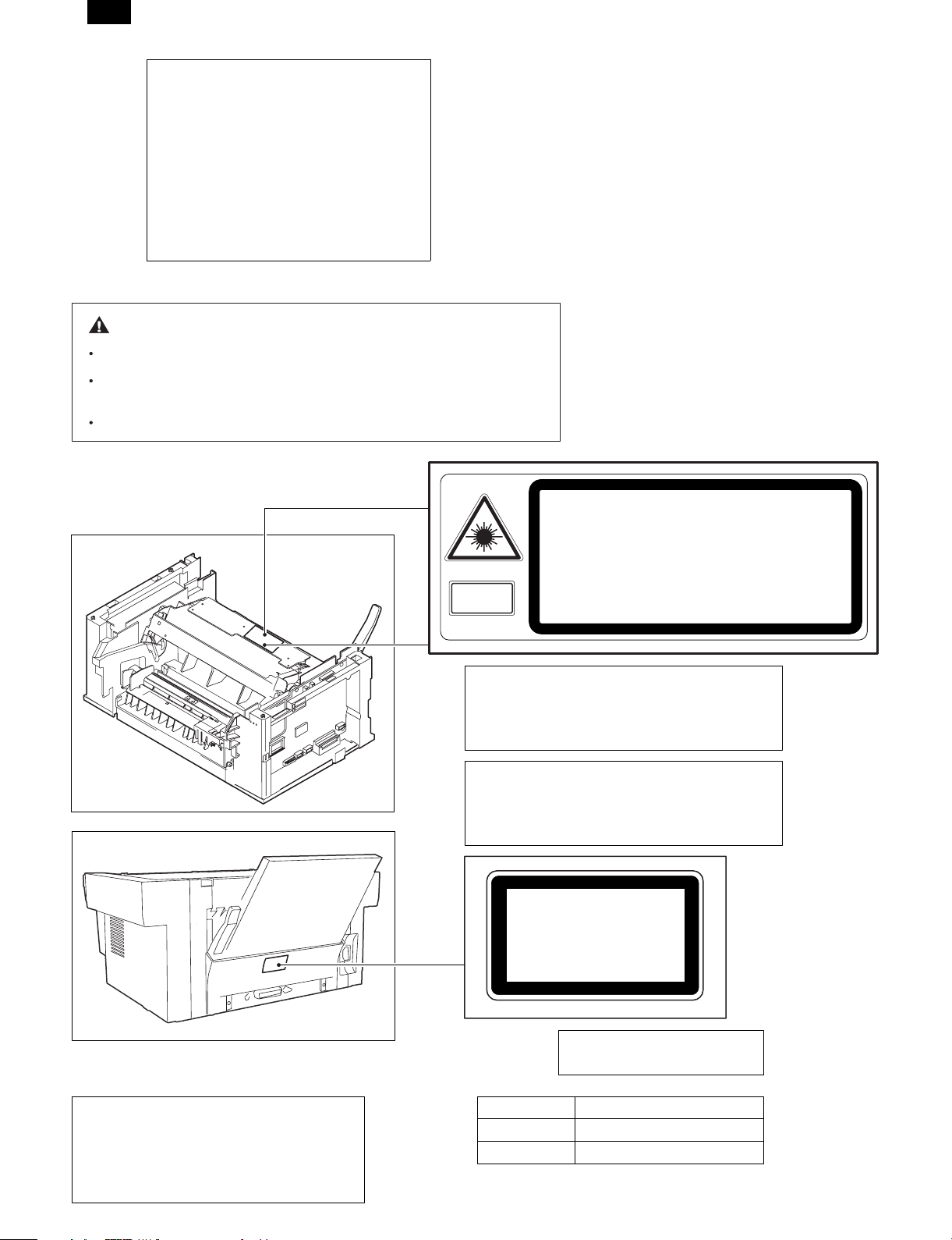
At the production line, the output power of
the scanner unit is adjusted to 0.33
MILLI-WATT PLUS 20 PCTS and is
maintained constant by the operation of the
Automatic Power Control (APC).
Even if the APC circuit fails in operation for
some reason, the maximum output power
will only be 15 MILLI-WATT 0.1 MICROSEC. giving an acceptable emission level
of 42 MICRO-WATT which is still-less than
the limit of CLASS-1 laser product.
Caution
The fusing unit is hot. Exercise care when inspecting it.
Do not switch the printer rapidly on and off. After turning the printer off,
wait 10 to 15 seconds before turning it back on.
Printer power must be turned off before installing any supplies.
CAUTION
VORSICHT
ADVARSEL
ADVERSEL
Laserstrahl
VAROITUS! LAITTEEN KÄYTTÄMINEN MUULLA
KUIN TÄSSÄ KÄYTTÖOHJEESSA MAINITULLA
TAVALLA SAATTAA ALTISTAA KÄYTTÄJÄN
TURVALLISUUSLUOKAN 1 YLITTÄVÄLLE
NÄKYMÄTTÖMÄLLE LASERSÄTEILYLLE.
VARNING - OM APPARATEN ANVÄNDS PÅ ANNAT
SÄTT ÄN I DENNA BRUKSANVISNING
SPECIFICERATS, KAN ANVÄNDAREN UTSÄTTAS
FÖR OSYNLIG LASERSTRÅLNING, SOM
ÖVERSKRIDER GRÄNSEN FÖR LASERKLASS 1.
VARNING
VARO!
INVISIBLE LASER RADIATION WHEN OPEN AND INTERLOCKS
DEFEATED AVOID EXPOSURE TO BEAM.
UNSICHTBARE LASERSTRAHLUNG WENN ABDECKUNG GEÖFFNET UND SICHERHEITSVERRIEGELUNG ÜBERBRÜCKT. NICHT DEM STRAHL AUSSETZEN.
USYNLIG LASERSTRÅLNING VED ÅBNING. NÅR SIKKERHEDSBRYDERE ER UDE AF FUNKTION. UNDGÅ UDSAETTELSE FOR STRÅLNING.
USYNLIG LASERSTRÅLING NÅR DEKSEL ÅPNES OG SIKKERHEDSLÅS BRYTES.
UNNGÅ EKSPONERING FOR STRÅLEN.
OSYNLIG LASERSTRÅLNING NÄR DENNA DEL ÄR ÖPPNAD OCH SPÄR RAR ÄR
URKOPPLADE. STRÅLEN ÄR FARLIG. BETRAKTA EJ STRÅLEN
AVATTAESSA JA SUOJALUKITUS OHITETTAESSA OLET ALTTIINA
NÄKYMÄTÖNTÄ LASERSÄTEILYLLE. ÄLÄ KATSO SÄTEESEEN
CLASS 1
LASER PRODUCT
.
.
The foregoing is applicable only to the 220V
model, 230V model and 240V model.
Caution
This product contains a low power laser
device. To ensure continued safety do not
remove any cover or attempt to gain access
to the inside of the product. Refer all
servicing to qualified personnel.
LASER KLASSE 1
LUOKAN 1 LASERLAITE
KLASS 1 LASER APPARAT
Wave length
Pulse times
Output Power
780 ± 15nm
(9.3 ± 2µs)/7mm
0.4mW ± 0.05mW
Page 3

Contents
[1] SYSTEM CONFIGURATION . . . . . . . . . . . . . . . . . . . . . . . . . . . . . . . . . . . . . . . . . . . . . . . . . . . . . . . . . . . . . . . . . . 1-1
1. LINEUP . . . . . . . . . . . . . . . . . . . . . . . . . . . . . . . . . . . . . . . . . . . . . . . . . . . . . . . . . . . . . . . . . . . . . . . . . . . . . . . . . 1-1
2. STRUCTURE . . . . . . . . . . . . . . . . . . . . . . . . . . . . . . . . . . . . . . . . . . . . . . . . . . . . . . . . . . . . . . . . . . . . . . . . . . . . 1-2
3. SOFTWARE . . . . . . . . . . . . . . . . . . . . . . . . . . . . . . . . . . . . . . . . . . . . . . . . . . . . . . . . . . . . . . . . . . . . . . . . . . . . . 1-2
4. OPERATING ENVIRONMENT . . . . . . . . . . . . . . . . . . . . . . . . . . . . . . . . . . . . . . . . . . . . . . . . . . . . . . . . . . . . . . . 1-2
[2] SPECIFICATIONS . . . . . . . . . . . . . . . . . . . . . . . . . . . . . . . . . . . . . . . . . . . . . . . . . . . . . . . . . . . . . . . . . . . . . . . . . . 2-1
1. BASIC SPECIFICATIONS . . . . . . . . . . . . . . . . . . . . . . . . . . . . . . . . . . . . . . . . . . . . . . . . . . . . . . . . . . . . . . . . . . 2-1
2. OPERATION (PERFORMANCE) . . . . . . . . . . . . . . . . . . . . . . . . . . . . . . . . . . . . . . . . . . . . . . . . . . . . . . . . . . . . . 2-1
3. Basic speficifications of facsimile . . . . . . . . . . . . . . . . . . . . . . . . . . . . . . . . . . . . . . . . . . . . . . . . . . . . . . . . . . . . . . 2-5
4. ENGINE SPECIFICATION . . . . . . . . . . . . . . . . . . . . . . . . . . . . . . . . . . . . . . . . . . . . . . . . . . . . . . . . . . . . . . . . . 2-13
[3] CONSUMABLE PARTS . . . . . . . . . . . . . . . . . . . . . . . . . . . . . . . . . . . . . . . . . . . . . . . . . . . . . . . . . . . . . . . . . . . . . . 3-1
1. Configuration . . . . . . . . . . . . . . . . . . . . . . . . . . . . . . . . . . . . . . . . . . . . . . . . . . . . . . . . . . . . . . . . . . . . . . . . . . . . . 3-1
2. List . . . . . . . . . . . . . . . . . . . . . . . . . . . . . . . . . . . . . . . . . . . . . . . . . . . . . . . . . . . . . . . . . . . . . . . . . . . . . . . . . . . . 3-1
3. Details . . . . . . . . . . . . . . . . . . . . . . . . . . . . . . . . . . . . . . . . . . . . . . . . . . . . . . . . . . . . . . . . . . . . . . . . . . . . . . . . . . 3-1
4. Paper specifications . . . . . . . . . . . . . . . . . . . . . . . . . . . . . . . . . . . . . . . . . . . . . . . . . . . . . . . . . . . . . . . . . . . . . . . 3-3
5. Standard density sample . . . . . . . . . . . . . . . . . . . . . . . . . . . . . . . . . . . . . . . . . . . . . . . . . . . . . . . . . . . . . . . . . . . 3-4
6. Environmental conditions . . . . . . . . . . . . . . . . . . . . . . . . . . . . . . . . . . . . . . . . . . . . . . . . . . . . . . . . . . . . . . . . . . . 3-5
[4] SET UP . . . . . . . . . . . . . . . . . . . . . . . . . . . . . . . . . . . . . . . . . . . . . . . . . . . . . . . . . . . . . . . . . . . . . . . . . . . . . . . . . . . 4-1
1. Installing conditions . . . . . . . . . . . . . . . . . . . . . . . . . . . . . . . . . . . . . . . . . . . . . . . . . . . . . . . . . . . . . . . . . . . . . . . . 4-1
2. Unpacking . . . . . . . . . . . . . . . . . . . . . . . . . . . . . . . . . . . . . . . . . . . . . . . . . . . . . . . . . . . . . . . . . . . . . . . . . . . . . . . 4-1
3. Parts and consumable parts setup . . . . . . . . . . . . . . . . . . . . . . . . . . . . . . . . . . . . . . . . . . . . . . . . . . . . . . . . . . . . 4-2
4. Cable connection . . . . . . . . . . . . . . . . . . . . . . . . . . . . . . . . . . . . . . . . . . . . . . . . . . . . . . . . . . . . . . . . . . . . . . . . . 4-4
5. Installing the printer and TWAIN (Scanner) driver software . . . . . . . . . . . . . . . . . . . . . . . . . . . . . . . . . . . . . . . . . 4-4
6. Setup FAX section . . . . . . . . . . . . . . . . . . . . . . . . . . . . . . . . . . . . . . . . . . . . . . . . . . . . . . . . . . . . . . . . . . . . . . . . . 4-6
7. Note for transport . . . . . . . . . . . . . . . . . . . . . . . . . . . . . . . . . . . . . . . . . . . . . . . . . . . . . . . . . . . . . . . . . . . . . . . . . . 4-7
[5] EXTERNAL VIEW AND INTERNAL STRUCTURE . . . . . . . . . . . . . . . . . . . . . . . . . . . . . . . . . . . . . . . . . . . . . . . . . 5-1
1. List . . . . . . . . . . . . . . . . . . . . . . . . . . . . . . . . . . . . . . . . . . . . . . . . . . . . . . . . . . . . . . . . . . . . . . . . . . . . . . . . . . . . 5-1
2. Contents . . . . . . . . . . . . . . . . . . . . . . . . . . . . . . . . . . . . . . . . . . . . . . . . . . . . . . . . . . . . . . . . . . . . . . . . . . . . . . . . 5-1
[6] MACHINE OPERATION . . . . . . . . . . . . . . . . . . . . . . . . . . . . . . . . . . . . . . . . . . . . . . . . . . . . . . . . . . . . . . . . . . . . . . 6-1
(1) Operation mode . . . . . . . . . . . . . . . . . . . . . . . . . . . . . . . . . . . . . . . . . . . . . . . . . . . . . . . . . . . . . . . . . . . . . . . . 6-1
(2) Machine status and display . . . . . . . . . . . . . . . . . . . . . . . . . . . . . . . . . . . . . . . . . . . . . . . . . . . . . . . . . . . . . . . . 6-1
(3) Relationship between the power save mode and the display and machine operations . . . . . . . . . . . . . . . . . . 6-3
(4) Consumable parts life and operation . . . . . . . . . . . . . . . . . . . . . . . . . . . . . . . . . . . . . . . . . . . . . . . . . . . . . . . . 6-3
(5) Selection between the ON LINE mode and the OFF L INE mo de . . . . . . . . . . . . . . . . . . . . . . . . . . . . . . . . . . . 6-2
(6) Paper width detection and machine operation . . . . . . . . . . . . . . . . . . . . . . . . . . . . . . . . . . . . . . . . . . . . . . . . . 6-3
(7) Auto copy function . . . . . . . . . . . . . . . . . . . . . . . . . . . . . . . . . . . . . . . . . . . . . . . . . . . . . . . . . . . . . . . . . . . . . . . 6-3
(8) AE level adjustment procedure . . . . . . . . . . . . . . . . . . . . . . . . . . . . . . . . . . . . . . . . . . . . . . . . . . . . . . . . . . . . . . 6-3
(9) Toner save mode setup and cancel . . . . . . . . . . . . . . . . . . . . . . . . . . . . . . . . . . . . . . . . . . . . . . . . . . . . . . . . . . 6-3
(10) Operation mode and priority . . . . . . . . . . . . . . . . . . . . . . . . . . . . . . . . . . . . . . . . . . . . . . . . . . . . . . . . . . . . . . . . 6-4
(11) Multi access operation table . . . . . . . . . . . . . . . . . . . . . . . . . . . . . . . . . . . . . . . . . . . . . . . . . . . . . . . . . . . . . . . . 6-4
(12) Machine errors and operations in each operation mode . . . . . . . . . . . . . . . . . . . . . . . . . . . . . . . . . . . . . . . . . . . 6-5
(13) Pre-heat mode, shut off mode operations . . . . . . . . . . . . . . . . . . . . . . . . . . . . . . . . . . . . . . . . . . . . . . . . . . . . . . 6-6
(14) Others . . . . . . . . . . . . . . . . . . . . . . . . . . . . . . . . . . . . . . . . . . . . . . . . . . . . . . . . . . . . . . . . . . . . . . . . . . . . . . . . . 6-6
[7] ADJUSTMENTS, SETTING . . . . . . . . . . . . . . . . . . . . . . . . . . . . . . . . . . . . . . . . . . . . . . . . . . . . . . . . . . . . . . . . . . . 7-1
1. List . . . . . . . . . . . . . . . . . . . . . . . . . . . . . . . . . . . . . . . . . . . . . . . . . . . . . . . . . . . . . . . . . . . . . . . . . . . . . . . . . . . . 7-1
2. Details . . . . . . . . . . . . . . . . . . . . . . . . . . . . . . . . . . . . . . . . . . . . . . . . . . . . . . . . . . . . . . . . . . . . . . . . . . . . . . . . . . 7-1
[8] SIMULATION (Test Command) – USER PROGRAM . . . . . . . . . . . . . . . . . . . . . . . . . . . . . . . . . . . . . . . . . . . . . . . 8-1
1. Simulation . . . . . . . . . . . . . . . . . . . . . . . . . . . . . . . . . . . . . . . . . . . . . . . . . . . . . . . . . . . . . . . . . . . . . . . . . . . . . . . 8-1
2. User program . . . . . . . . . . . . . . . . . . . . . . . . . . . . . . . . . . . . . . . . . . . . . . . . . . . . . . . . . . . . . . . . . . . . . . . . . . . 8-14
3. Printing Out Reports . . . . . . . . . . . . . . . . . . . . . . . . . . . . . . . . . . . . . . . . . . . . . . . . . . . . . . . . . . . . . . . . . . . . . . . 8-15
4. FAX simulations . . . . . . . . . . . . . . . . . . . . . . . . . . . . . . . . . . . . . . . . . . . . . . . . . . . . . . . . . . . . . . . . . . . . . . . . . . 8-16
5. Software switch for FAX . . . . . . . . . . . . . . . . . . . . . . . . . . . . . . . . . . . . . . . . . . . . . . . . . . . . . . . . . . . . . . . . . . . . 8-21
[9] DISASSEMBLY, ASSEMBLY, MAINTENANCE . . . . . . . . . . . . . . . . . . . . . . . . . . . . . . . . . . . . . . . . . . . . . . . . . . . 9-1
1. List . . . . . . . . . . . . . . . . . . . . . . . . . . . . . . . . . . . . . . . . . . . . . . . . . . . . . . . . . . . . . . . . . . . . . . . . . . . . . . . . . . . . 9-1
[10] TROUBLESHOOTING . . . . . . . . . . . . . . . . . . . . . . . . . . . . . . . . . . . . . . . . . . . . . . . . . . . . . . . . . . . . . . . . . . . . . . 10-1
1. Self diag message and troubleshooting . . . . . . . . . . . . . . . . . . . . . . . . . . . . . . . . . . . . . . . . . . . . . . . . . . . . . . . 10-1
2. Troubleshooting of print operation (Printer mode) . . . . . . . . . . . . . . . . . . . . . . . . . . . . . . . . . . . . . . . . . . . . . . 10-18
3. Troubleshooting of copy/print quality . . . . . . . . . . . . . . . . . . . . . . . . . . . . . . . . . . . . . . . . . . . . . . . . . . . . . . . . 10-19
FO-3800M
Page 4
FO-3800M
[1] SYSTEM CONFIGURATION
1. LINEUP
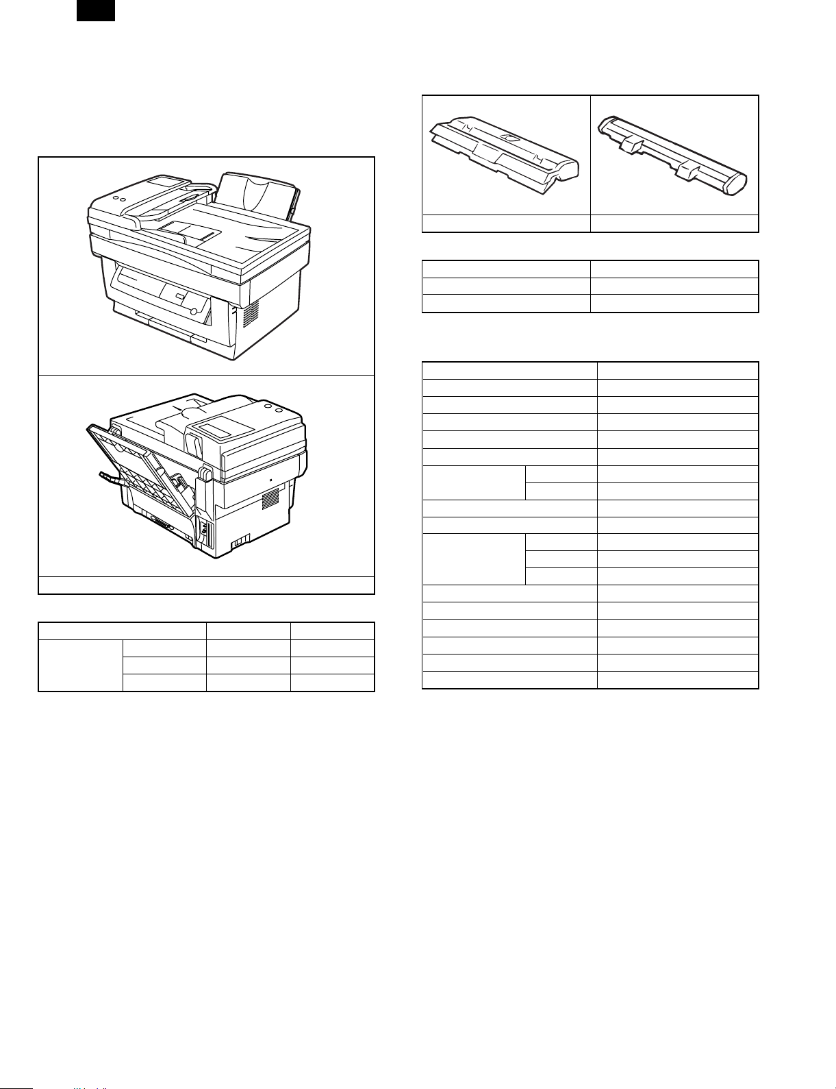
A. Main Unit
(1) Appearance
FO-3800M
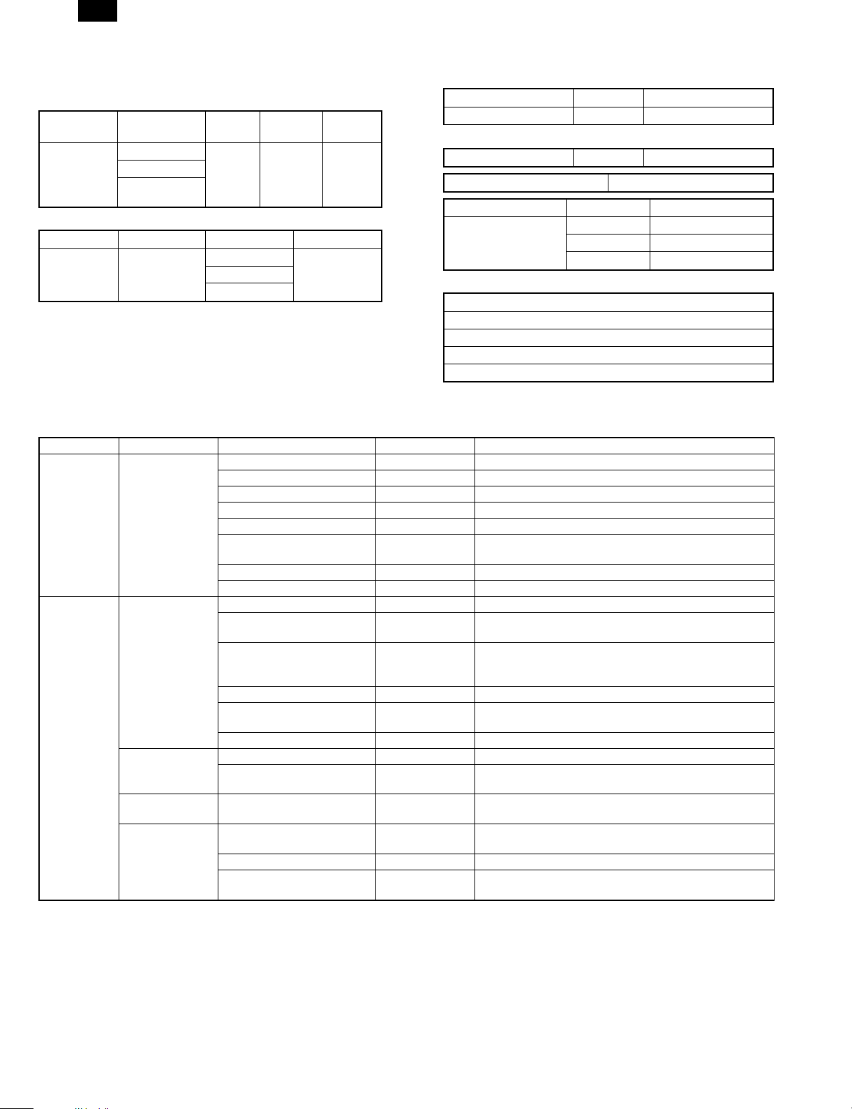
(2) Function/Equipment
Item FO-3800M Notes
Function/
Equipment
Copy (SPF) Yes
FAX (SPF) Yes
Printer Yes
B. Supplies
(1) Appearance
TD cartridge Drum cartridge
(2) Supplies List
Items Model/Parts code
Drum cartridge FO-29DR
TD cartridge FO-29ND
C. Accessories
Accessories list
Model FO-3800M
Tray (Universal) Included
Drum cartridge Installed
TD cartridge (1.5K) Included
Original cover Included
AC power cord Included UL, CSA PLG
Printer cable IEEE1284 Included
USB N/A
Phone cable Included
Driver soft CD-ROM
Operation manual Copier Included (SEC*)
Printer Included (SEC*)
FAX Included
Warranty card (Registration card) Included (SEC*) in manual
MSDS sheets Included
POP label N/A
Dust cover N/A
User card (Aiyousya card) N/A
Digital logo N/A
1 – 1
Page 5
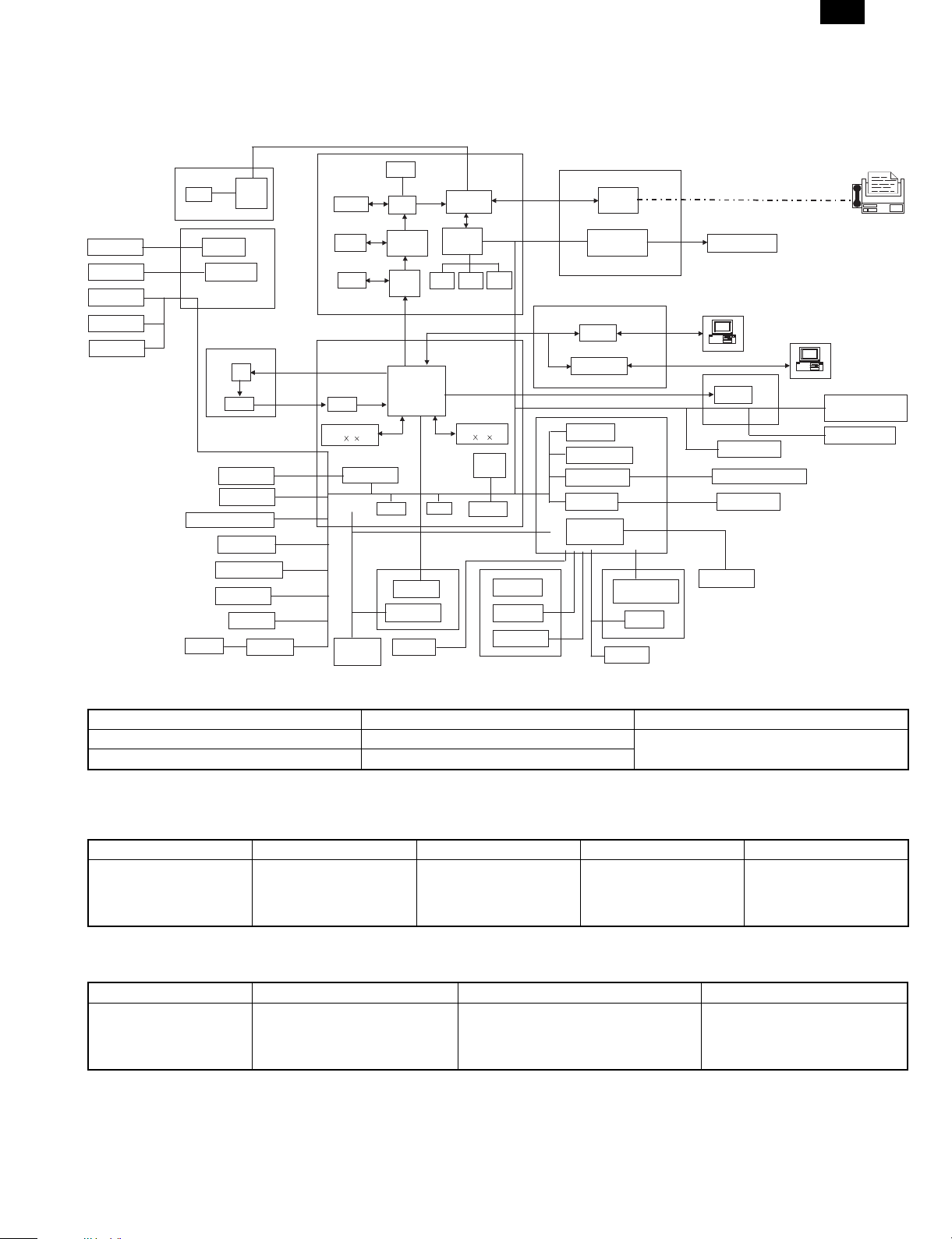
2. STRUCTURE
A. Hardware
Block diagram
FO-3800M
SPF solenoid
Document
detection SW
Paper in sensor
Open/Close SW
LCD PWB
LCD
SPF relay PWB
Home position sensor
Lamp
Driver
Motor driverScanner motor
CCD PWB
CCD
Amplifier
Scanner motor
FAN motor
Operation panel
Paper size sensor
Toner sensor
1-chip
CPU
Paper exit
sensor
Inverter
FAX PWB
DRAM
SRAM
DRAM
Main control PWB
A/D
SRAM
32k
8 2
Motor driver
Power supply
unit
RTC
ASIC
Compress
/Expand
LC8213
ASIC
ROM
Heat roller
Heater lamp
Temperature
fuse
Image
process
ASIC
Thermistor
Controller
FX200
CPU/DSP
FX164
ROM DRAM
RAM
SRAM
DRAM
1M
16 2
CPU
H8S
EEPROM
Developing cartridge
Doctor
Developing
roller
Earth sheet
I/F PWB
LIU PWB
Driver
USB converter
chip
Paper in sensor
Cover SW
Driver
Motor driver
High voltage unit
LIU control
Speaker control
High voltage PWB
Main charger roller
OPC drum cartridge
Separation
electrode
Drum
Speaker
LSU unit
Laser
Paper exit sensor
Pick-up solenoid
Main motor
Transfer roller
Laser beam
sensor
Polygon-motor
Fax
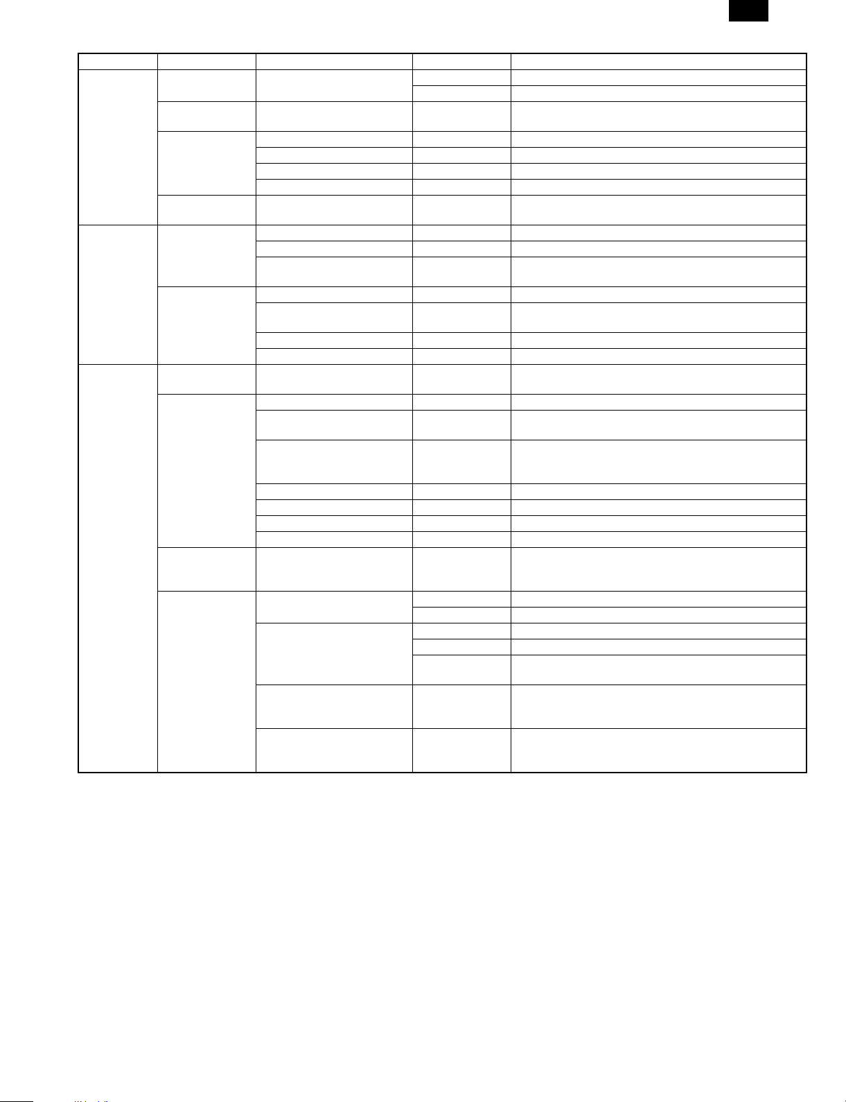
3. SOFTW ARE
Items Contents Media
GDI Printer driver Printer driver CD-ROM
Twain driver Scanner driver
4. OPERA TING ENVIRONMENT
(1) System requirements
Host computer Operating system Emulation Plug and play Network
IBM PC/AT or
100% compatible
(Supported ECP mode)
∗ MS-DOS 3.3 + (Printer only)
(2) Interface
Type Host computer Operating system Protocol
IEEE1284P × 1 IBM PC/AT or
MS-DOS 3.3 +
MS-Windows 3.1X or later
MS-Windows 95/98
MS-Windows NT 4.0
100% compatible
Sleek type GDI (Printer)
Twain (Scanner)
MS-DOS 3.3 +
MS-Windows 3.1X or later
MS-Windows 95
MS-Windows NT 4.0
Supported Not supported
Peppy
Nibble
ECP
1 – 2
Page 6
FO-3800M
[2] SPECIFICATIONS
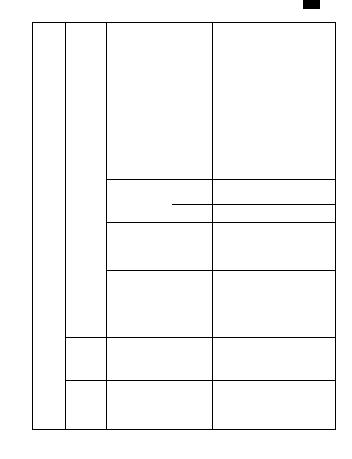
1. BASIC SPECIFICATIONS
(1) Types
Model type Desktop type
Scanning type SPF/Flat bed/Monochrome type
Printing type
(Emulation type)
FAX type G3
(2) Target users
Print Volume
Average 600 sheet/month
Maximum 1,000 sheet/month
(3) Operating environment
Printer mode
<1> System requirements
Host computer Operating system Emulation Network
IBM PC/AT or
100% compatible
<2> Interface
Type Host computer Operating system Protocol
IEEE1284 P
(1 ports)
MS-DOS 3.3 + (Printer only)
∗
IBM PC/AT or
100% compatible
(4) Outer dimensions
Machine 460 × 425 × 307 mm (18.2" × 16.8" × 12.1")
(5) Weight
Packaged 15.10 Kg
Machine 13.30 Kg
(6) Machine life
60K prints or 5 years
2. OPERATION (PERFORMANCE)
A. Common operation
Warm-up/Jam recovery
a. Warm-up time
Warm-up time after power ON 0 sec
Recovery time from power save mode 0 sec
Jam recovery time 0 sec
b. Jam recovery time
B. Copy mode
(1) Max. original size
8-1/2" × 14", A4 (210 × 356 mm) (SPF mode)
8-1/2" × 11", A4 (210 × 297 mm) (Platen mode)
Electronic photographic type
GDI
MS-DOS 3.3 +
MS-Windows 3.1X or later
MS-Windows 95/98
MS-Windows NT 4.0
MS-DOS 3.3 +
MS-Windows 3.1X or later
MS-Windows 95/98
MS-Windows NT 4.0
Sleek type
GDI
Twain
Not
supported
Peppy
Nibble
ECP
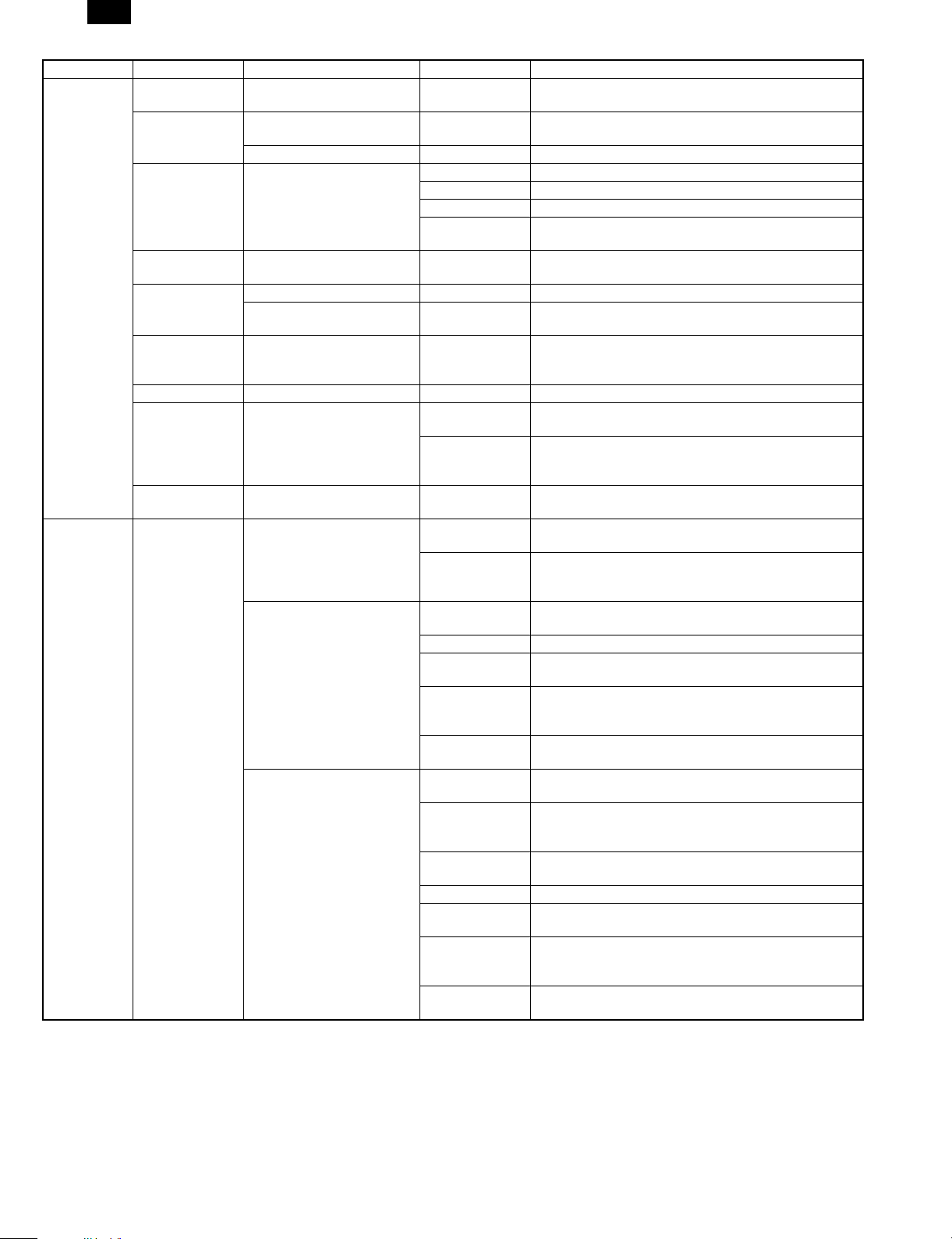
(2) Exposure mode
Exposure mode Steps for exposure Toner save mode
Automatic — Available
Manual 5 steps Available
Photo 5 steps Non
(3) Copy ratio
Copy ratio Zoom ratio range/fixed ratio
Zoom mode 50% to 200% (151 steps in 1% increments)
Fixed ratio mode
(AB system)
Fixed ratio mode
(Inch system)
Zooming accuracy Same size copying: 100% ± 1.0%
50, 70, 86, 100, 141, 200%
50, 64, 78, 100, 129, 200%
Enlargement copying : Set copy ratio ± 1.0%
Reduction copying: Set copy ratio ± 1.0%
(4) Job speed
a. First copy time
Mode SPF mode Platen mode
Normal mode 13 sec 10 sec
Preheat mode 21 sec 21 sec
Auto power shut-off mode 23 sec 23 sec
b. Copying speed for each paper size and reduction/enlargement
(CPM)
Copy ratio
Paper size
A4
(Short edge feed)
B5
(Short edge feed)
8-1/2" × 14"
(Short edge feed)
8-1/2" × 11"
(Short edge feed)
Same size
8 CPM 8 CPM 8 CPM
8 CPM 8 CPM 8 CPM
7 CPM 7 CPM 7 CPM
8 CPM 8 CPM 8 CPM
Reduction
(50% to 99%)
Enlargement
(101% to 200%)
(5) Max. number of continuous copies
50 copies
(6) Exposure
a. Exposure mode/Processing
Exposure mode Function
Automatic Error diffusion
Manual Error diffusion
Photo Error diffusion
b. Toner save
Yield of Toner save mode 5% area coverage
(When using 3K toner cartridge)
c. Zooming type
Main scanning direction Software computation
Sub scanning direction Scanning speed/Document feed speed
d. Resolution
Scanning
∗
Main scanning direction Sub scanning direction
Standard resolution
Scanner 400 dpi — Scanner 600 dpi —
Copier 600 dpi — Copier 600 dpi —
Virtual
resolution
Standard resolution
Virtual
resolution
2 – 1
Page 7
FO-3800M
Printing
∗
Main scanning direction Sub scanning direction
Standard
resolution
Virtual
resolution
Standard
resolution
600 dpi — 600 dpi —
Copy ratio
Position
Center Corner
Same size 5.0 line/mm 4.5 line/mm
Enlargement (101% to 200%) 5.0 line/mm 4.5 line/mm
Reduction (50% to 99%) 4.0 line/mm 4.0 line/mm
e. Exposure gradient
Error diffusion method.
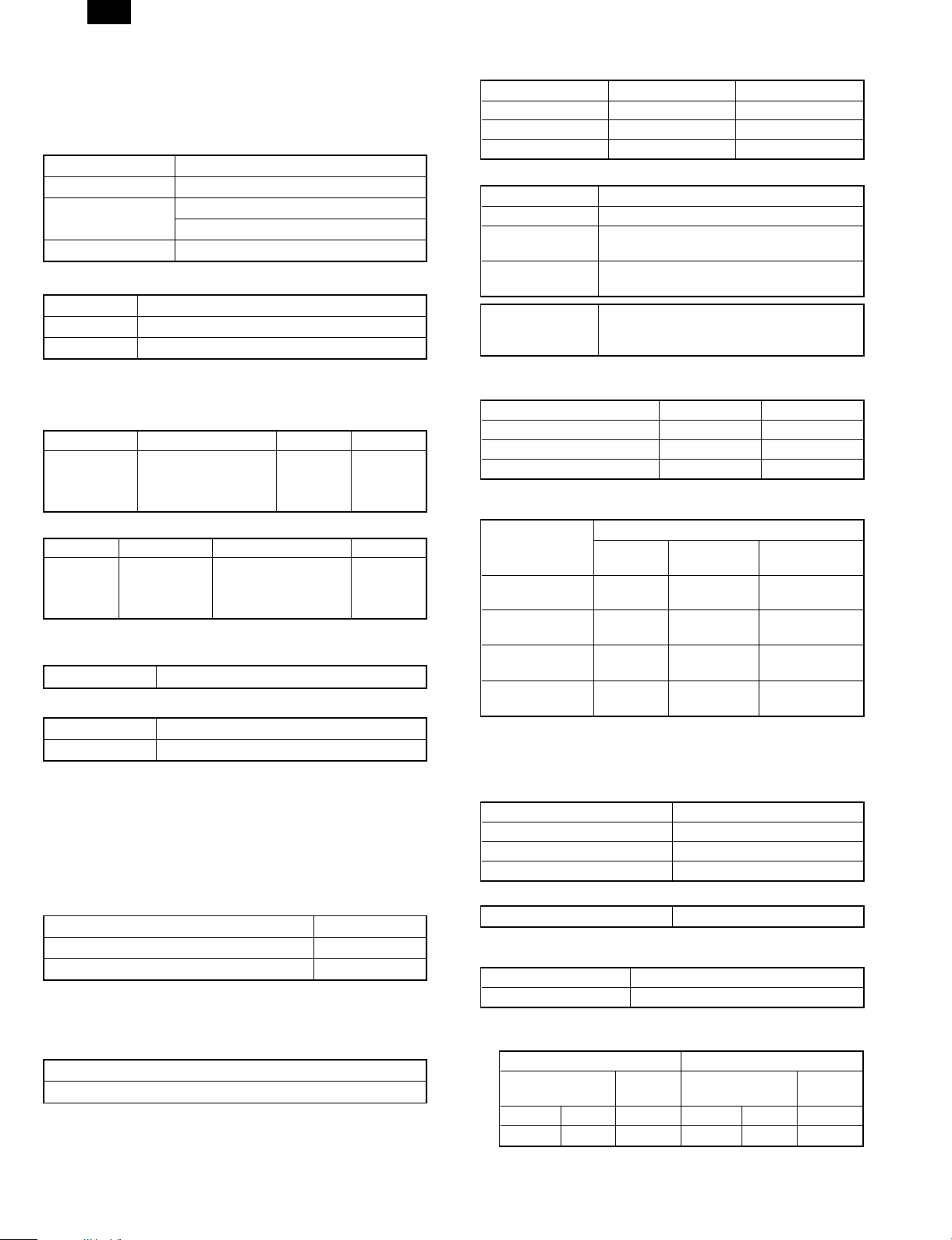
f. Copy (Print) Area
2.0 mm (Std)
3.0 mm (Max)
(Top)
Printed image
(printable area)
Virtual
resolution
1 ~ 5.0 mm
Paper
transfer
direction
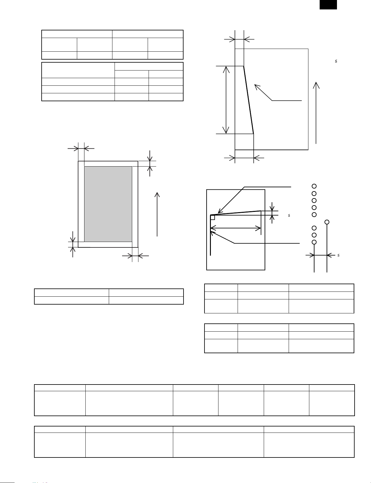
h. Skew (Diagonality)
D1
| D1-D2 |
269mm
Printed vertical line
D2
Paper
transfer
direction
i. Distortion
Orthogonality Image phase misalignment
Print horizonal line
D
1mm
| D |
203mm
1.7mm
2.5 mm (Std)
5.0 mm (Max)
(Bottom)
2.0 mm (Std)
3.0 mm (Max)
g. Image misalignment
Off center 0 ± 2.0 mm or below
Horizontal misalignment 0 ± 2.0 mm or below
j. Original size
AB system A6 (105 × 148.5 mm) A4 (210 × 297 mm)
Inch system 3-7/8" × 5-7/8" 8-1/2" × 14" (SPF mode)
Printed vertical line
Minimum Maximum
8-1/2" × 11" (Platen mode)
k. Paper size
Minimum Maximum
AB system A6 (105 × 148.5 mm) A4 (210 × 297 mm)
Inch system 3-7/8" × 5-7/8" 8-1/2" × 14" (SPF mode)
8-1/2" × 11" (Platen mode)
C. Printer mode
(1) System requirements
a. Operating conditions
Host computer Operating system Emulation Driver Plug and play Network
IBM PC/AT or
100% compatible
b. Interface
Type Host computer Operating system Protocol
IEEE1284 P × 1 IBM PC/AT or 100% compatible MS-DOS 3.3 +
MS-DOS 3.3 +
MS-Windows 3.1X or later
MS-Windows 95/98
MS-Windows NT 4.0
Sleek type GDI GDI printer driver Supported Not supported
Peppy
MS-Windows 3.1X or later
Nibble
MS-Windows 95/98
MS-Windows NT 4.0
60µm
2 – 2
Page 8
FO-3800M
(2) Job speed
a. First print time
Mode Paper feed mode
Normal 20 sec
Power save 20 sec
(A4 (8-1/2" × 11"), Not including the communication time to the
host PC and the set up time of polygon mirror)
b. Print speed
Paper size
8 ppm (A4, 8-1/2" × 11", Sharp standard paper)
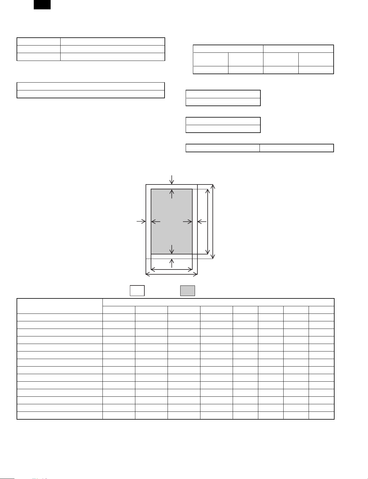
e. Print area
(Portrait)
(3) Image quality
a. Resolution
∗
b. Gradient
Binary (Dither pattern method)
c. Image treatment
d. Toner save
Yield of toner save mode 5% area coverage
G
Printing
Main scanning direction Sub scanning direction
Standard
resolution
Virtual
resolution
Standard
resolution
Virtual
resolution
600 dpi∗ — 600 dpi∗ —
∗ 300 dpi selectable
Gradient
Image treatment
Dither pattern method
Paper size
E
H
C
A
Physical Page
ABCDEFGH
D
F
Logical Page
B
Value
LETTER 2550/5100 3300/6600 2456/4904 3200/6400 50/100 44/96 50/100 50/100
LEGAL 2550/5100 4200/8400 2456/4904 4100/8200 50/100 44/96 50/100 50/100
EXECUTIVE 2175/4350 3150/6300 2080/4152 3050/6100 50/100 45/98 50/100 50/100
A4 2480/4960 3507/7015 2384/4760 3407/6815 50/100 46/100 50/100 50/100
A5 1748/3496 2480/4960 1648/3296 2380/4760 50/100 50/100 50/100 50/100
COM-10 1236/2473 2850/5700 1136/2280 2750/5500 50/100 50/93 50/100 50/100
MONARCH 1161/2323 2250/4500 1064/2128 2150/4300 50/100 47/95 50/100 50/100
C5 1912/3825 2703/5407 1816/3632 2603/5207 50/100 46/93 50/100 50/100
DL 1299/2598 2598/5196 1200/2400 2498/4996 50/100 49/98 50/100 50/100
B5 2149/4299 3035/6070 2056/4104 2935/5870 50/100 43/95 50/100 50/100
FOOLSCAP 2550/5100 3720/7440 2456/4904 3620/7240 50/100 44/96 50/100 50/100
FOLIO 2550/5100 3900/7800 2456/4904 3800/7600 50/100 44/96 50/100 50/100
Government Printed Postcard 1181/2362 1748/3496 1088/2168 1648/3296 50/100 43/94 50/100 50/100
Japanese Envelop (Choukei 3) 1417/2834 2775/5551 1320/2640 2675/5351 50/100 47/94 50/100 50/100
A. Physical page width
B. Physical page height
C. Logical page width
D. Width difference between Physical page and HP-GL-2 picture
frame
E. Height difference between Physical page and Logical page
F. Height difference between Physical page and HP-GL-2 picture
frame
G. Printable width
H. Distance between Top edge and Bottom edge in Physical page
2 – 3
Page 9
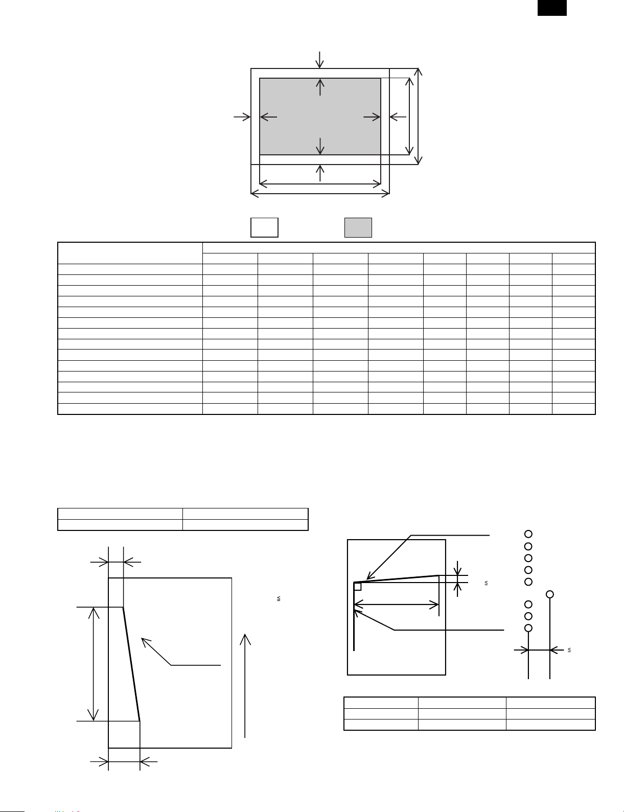
(Landscape)
FO-3800M
G
EF
B
D
H
C
A
Paper size
Physical Page
ABCDEFGH
Logical Page
Value
LETTER 3300/6600 2550/5100 3200/6400 2456/4904 50/100 50/100 50/100 44/96
LEGAL 4200/8400 2550/5100 4100/8200 2456/4904 50/100 50/100 50/100 44/96
EXECUTIVE 3150/6300 2175/4350 3050/6100 2080/4152 50/100 50/100 50/100 45/98
A4 3507/7015 2480/4960 3407/6815 2384/4760 50/100 50/100 50/100 46/100
A5 2480/4960 1748/3496 2380/4760 1648/3296 50/100 50/100 50/100 50/100
COM-10 2850/5700 1236/2473 2750/5500 1136/2280 50/100 50/100 50/100 50/93
MONARCH 2250/4500 1161/2323 2150/4300 1064/2128 50/100 50/100 50/100 47/95
C5 2703/5407 1912/3825 2603/5207 1816/3632 50/100 50/100 50/100 46/93
DL 2598/5196 1299/2598 2498/4996 1200/2400 50/100 50/100 50/100 49/98
B5 3035/6070 2149/4299 2935/5870 2056/4104 50/100 50/100 50/100 43/95
FOOLSCAP 3720/7440 2550/5100 3620/7240 2456/4904 50/100 50/100 50/100 44/96
FOLIO 3900/7800 2550/5100 3800/7600 2456/4904 50/100 50/100 50/100 44/96
Government Printed Postcard 1748/3496 1181/2362 1648/3296 1088/2168 50/100 50/100 50/100 43/94
Japanese Envelope (Choukei 3) 2775/5551 1417/2834 2675/5351 1320/2640 50/100 50/100 50/100 47/94
A. Physical page width
B. Physical page height
C. Logical page width
D. Width difference between Physical page and HP-GL-2 picture
F. Height difference between Physical page and HP-GL-2 picture
frame
G. Printable width
H. Distance between Top edge and Bottom edge in Physical page
frame
E. Height difference between Physical page and Logical page
f. Image misalignment
Off center 0 ± 2.0 mm or below
Horizontal misalignment 0 ± 2.0 mm or below
g. Skew (Diagonality)
D1
269mm
Printed vertical line
D2
| D1-D2 |
Paper
transfer
direction
1.7mm
2 – 4
h. Distortion
Orthogonality Image phase misalignment
Print horizonal line
D
1mm
| D |
203mm
Printed vertical line
i. Paper size
Minimum Maximum
AB system A6 (105 × 148.5 mm) A4 (210 × 297 mm)
Inch system 3-7/8" × 8-7/8" 8-1/2" × 14"
60µm
Page 10
FO-3800M
D. Scanner mode
(1) System requirements
a. Operating conditions
Host
computer
IBM PC/AT
or compatible
(Supported
ECP mode)
b. Interface
Type Host computer Operating Protocol
IEEE 1284 P IBM PC/AT or
Operating
system
Windows 3.1x Twain
Windows 95/98
Windows nt 4.0
compatible
Software/
Driver
driver
Windows 3.1x ECP
Windows 95/98
Windows nt 4.0
Plug and
play
Supported Not
Network
supported
(2) Image quality
Resolution
∗
Main scanning direction 300/400/600 600 dpi (Vertual)
Sub scanning 300/400/600 —
Scanning mode
∗
Monochrome 8 bit Scan 1 bit Output to
Image density adjustment 5 levels
Scan mode Image process
Scan mode and
Image process
Scan size
∗
8.5" × 14" (SPF mode only)
8.5" × 11"
A4
B5
A5
Text & Picture Error diffusion method
Text Error diffusion method
Picture Error diffusion method
3. Basic specifications of facsimile
Large Item Middle Item Small Item Sub Item Spec.
Transmission time Approx. 6 sec. (G3 ECM/14,400bps)
Transmission Method V17, V29, V27TER, V33 (Only Receiving)
Communication
system
Scanning
system
Transmission
method
Document size
Automatic
document
detection
Transmission
mode
Document
loading capacity,
scanning cycle
(SPF
performance)
Compression method MH, MR, MMR
Modem speed 14,400bps → 2,400bps automatic fall back
Mutual transmission G3
Line used
Number of lines used 1 line (cannot be added)
ECM YES
Max. document width OC: 210mm SPF: 216mm
Unscannable region
Transmitted document size
Document designation YES
Two-sided document
designation
Long document 14"
SPF YES
OC NO
SPF/OC transmission
changeover
Continuous, automatic feed
compatibility
Document loading capacity SPF: 30 sheets (MAX)
Document scanning cycle
Public Switched Telephone Network (PSTN), Private
Branch exchange (PBX),
Leading edge 1 to 4 mm, trailing edge: 4mm max., left
end + right end: either 4mm max.
SPF: Max. 8.5" × 14 "
SPF: Min. 8.5" × 5 .5" (Inch System)
SPF: 210 × 148mm (AB System)
NO
NO
NO
8 sheets/min. (Standard mode, A4R memory
transmission)
2 – 5
Page 11
Large Item Middle Item Small Item Sub Item Spec.
Equivalent to 256 scales
600dpi
Letter/Legal (Inch System)
A4 (AB System)
By failing paper pick up
20 groups (including the other parties registered to
rapid key dialing)
By using the SEARCH key: Any other parties
registered to speed dialing and rapid key dialing can
be searched for using the first letter.
Time of day specified for transmission or polling.
Max.3
Beginning with the page where error occurred
Max. 20 transmissions
YES
Image
processing
system
Print system
Transmission
function
system
Half tone
reproduction
Contrast
adjustment
Resolution
selection
Printer section
resolution
Printing size
Print paper
Easy dialing
function
Easy dialing
function
Time
designation
function
Recall mode
Half tone (photo mode)
Contrast selection Manual in 3 stages (AE)
Standard 8 dot / mm × 3.85 line / mm
Fine 8 dot / mm × 7.7 line / mm
Super fine 8 dot / mm × 15.4 line / mm
Finest NO
Max. printing width 215.9 mm
Print paper size detection YES (Only width): A4/Letter or small size
Printing size
Cassette capacity 250 × 1
Print paper absence
detection
Exit Paper Tray Full censor NO
Feed Paper cassette
Rapid key dialing 20 other parties
Speed dialing 100 other parties
Group dialing
Phonebook transmission
Chain dialing YES
Redialing The last number dialed is saved
Program NO
Mode recall NO
Time specified
transmission/polling
Automatic recall mode
when other party is busy
Recall mode when
communication error occurs
Number of transmissions
counted in recall mode
simultaneously
Subsequent transmission
reservation override in
recall mode
Resolution 8 dot /mm × 7.7 line / mm (Fixed)
Intervals 1 to 15 minutes
Count 1 to 14 times/0: no re-transmission
Intervals 1 to 15 minutes
Count 1 to 14 times/0: no re-transmission
Transmitted
Pages
FO-3800M
2 – 6
Page 12

FO-3800M
Large Item Middle Item Small Item Sub Item Spec.
Transmission
function
system
Memory Transmission/direct
transmission
Line sound
monitoring
function
Broadcast
function
Confidential
function
Batch
transmission
function
Priority function
Multiple
message
transmission
function
Rotational
Transmission
Book
document
transmission
Memory
Transmission
Number of
transmission
Reservations
that can be
made
Processing
when memory
Memory transmission
Direct transmission YES
Default setting By Memory All Clear
Dialing confirmation
monitoring
Broadcast transmission
Group dialing
Relay transmission
Relay transmission
Confidential transmission
Batch transmission NO
Transmission reservation
interrupt
Broadcast interrupt YES
Recall mode interrupt YES
Multiple message
transmission
Rotational transmission Paper size NO
Book document
transmission
is full
Setting change
After
Transmission
Setting
Number of
destinations
Transmission
method
Usable
numbers
Instructing
Station
Relay station NO
Multiple relay NO
Number of
relay groups
Number of
Receiving
stations that
may be
Specified per
Group
Other party’s
Station
Transmission
method
YES
Max. 20
Transmission is cancelled when using Timer, Group
or Broadcast function. Only scanned’ data is
transmitted.
∗ The number of pages to be actually sent does not
always correspond to the one passing through the
SPF in case of communication error.
∗ The transmission is cancelled when communication
error occurs.
∗ If the reverse sending is selected, the transmission
is cancelled.
NO
YES (Service Man diagnostic.)
50 destinations (Including the Group Dial)
Broadcast key, group key
Rapid or Speed keys
Transmitted to group registered to rapid keys or
speed dial.
NO
NO
NO
NO
NO
NO
YES (From OC mode)
2 – 7
Page 13
Large Item Middle Item Small Item Sub Item Spec.
Consecutive
page
transmission
(page splitting)
Remote
Transmission
Check by
other Party’s
number
Check by
Matching of
System
number (user’s
own machine)
and ID number
(other party’s
Machine)
(between
Sharp
machines only)
Number of calls
Automatic
phone/fax
switching
Manual
receiving setting
Number of
Switching calls
to automatic
Receiving in
manual
receiving mode
Answering
Machine mode
Automatically
switch to
automatic
receive
Quiet detect
time
Reduction
made within
Regular size
By received
data print size
Designation
Substitute
Receiving into
Memory
Forced
memory
receiving
Received data
override Output
NO
YES (From Memory)
NO
NO
YES
Automatic receiving (can be switched to A.M mode or
manual receiving in key operator program)
0 to 9 times (factory-set to twice: can be changed in
key operator program)
- The external telephone rings once if set the
number of calls for automatic receiving to 0 times.
NO
YES
OFF/1 to 9 times
YES
ON / OFF
OFF/ 1 to 10 sec.
NO
YES (ON/OFF in key operator program)
YES
Only when data cannot be output
NO
NO
Transmission
function
system
Receiving
function
system
Book
document
transmission
OK stamp OK stamp NO
Remote
transmission
(polling
transmission
function)
Reverse
sending
Receiving mode
Receiving mode
Receiving
mode timer
switching
Variable scale
factor receiving
Memory
receiving
function
Book document
transmission
Remote transmission
(Memory Polling)
Protective function
Default setting
Automatic receiving
Manual receiving
Manual receiving
Telephone message
receiver connection
Reduction
Enlargement NO
Substitute receiving into
memory
FO-3800M
2 – 8
Page 14
FO-3800M
Large Item Middle Item Small Item Sub Item Spec.
Transfer at occurrence of
trouble
Receiving of only specified
number enabled
Anti junk fax mode YES (ON/OFF) 10 group, 20 letters
Sender NO
Confidential receiving
Split size YES
Split receiving setting
Transmission request
Speed dialing
Speed dialing
Rapid key dialing
Mailbox NO
Mailbox name NO
Confidential ID
code
Transmission
Request
Resolution at
transmission
Request
Number of
other parties
Number of
other party’s
Number digits
Registered
name
earched letters Up to 1 letter
User tag
Classification
International
communication
mode setting
Transmission
method
Number of
other parties
Number of
other party’s
Number digits
Registered
name
Searched letters Up to 1 letter
User tag
Classification
International
communication
mode setting
Transmission
method
YES
NO
NO
NO
YES (according to paper selection condition in key
operator program)
NO
YES
Depends on the Sending Machine.
NO
100 other parties
20 digits
20 letters (may be omitted)
NO
NO
Speed dialing key + (00 to 99) + start key
20 other parties
20 digits
20 letters (may be omitted)
NO
NO
Rapid key dialing
Receiving
function
system
Registration
system
Transfer
Number
specified
receiving
Confidential
function
Rotational
receiving
Split receiving
Two-sided
document
receiving
2-in-1 receiving NO
Transmission
request (polling
receiving
function)
Turnaround
transmission
Number
registration
2 – 9
Page 15
Large Item Middle Item Small Item Sub Item Spec.
Registration
system
Telephone
Function
System
Registration
keys
Max. number
of registered
other parties
per group
Group dialing
Number
registration
Program
Batch
Sender
Registration
Transmission
request/remote
transmission
enable number
registration
Transmission
request/remote
transmission
enable number
registration
Letter input
Registered
data read-out,
read-in
Date & time
adjustment
Date indication
change
Backup
Handset NO
On-hook YES
Hold NO
Pause YES (2 second fixed)
Phone
transmission at
power failure
Ringer volume Adjusted in key operator program
Speaker volume
Tone pulse
switching
Sender registration
Transmission request
enable number
System number
ID number
Input method Key input YES
Letters that may be input Characters Alphanumeric characters, symbols
Registered data backup at
power failure
Registrable
Number
Registered
name
Searched letters NO
User tag
Classification
Transmission
method
Number of
programs
Registerable
item
Registered
name
Calling method NO
Setting change
After calling
Registration key NO
Number of
other parties
Registration
method
Sender’s name 24 letters, registered in key operator program
Sender’s
number
Transmission
Request
source Number
Registration
System
number
Registration
ID number
Registration
Rapid keys
50 other parties
Numbers registered to speed dialing and rapid key
dialing.
20 letters (may be omitted)
NO
Group dialing
NO
NO
NO
NO
NO
NO
20 digits, registered in key operator program
NO
NO
NO
NO
Registered in key operator program
Support terms is from 1990 to 2089.
NO
SRAM used, built-in battery-backed
NO
Adjusted by pressing arrow keys on the fax control
panel
Switched between 10 pps and TONE in key operator
program (North America)
FO-3800M
2 – 10
Page 16
FO-3800M
Large Item Middle Item Small Item Sub Item Spec.
Telephone
Function
System
Fax
Memory
Additional
information
printing
function for
transmission
Additional
printing
function for
receiving
Record
table
system
External
telephone
connection
Automatic
telephone/fax
switching
Memory
capacity
Memory Back
up
Memory
Contents
(transmission
reservation)
confirmation
Memory
remain
indication
Page counter NO
Date printing
Cover function Cover item
Transmission
message
Sender printing
function
Index printing YES
Communication
record function
Remote receiving switching YES (switching number in 1 digit +**) 0 to 9
Audio response NO
Response voice recording NO
Standard 2MB (Approx. 120 pages/A4)
Option NO
LCD indication NO
Print out YES
Date indication change NO
Other party’s
name
Other party’s
number
Sender’s name YES
Sender’s
number
Transmission
message
Regular message
User message NO
Sender’s number 20 digits
Sender’s name 24 letters
Communication record
table size
Communication record
memory capacity
Number of
communications
Time-specified
output
Communication record
table
Time-specified
communication table
Confidential receiving
confirmation table
When
recording
Memory is full
Printing
sequence
Department-bydepartment
output
YES
NO
NO
YES (Memory available percent display 3 digits in %
on LCD
YES (Year: month: day/ year in 4 digits)
LCD: 2 digits / Print: 4 digits
YES
YES
YES
YES
NO MESSAGE/URGENT/
IMPORTANT/CONFIDENTIAL/PLS.DISTRIBUTE/PLS.
CALL BACK
A4: AB System
LETTER, Legal: Inch System
(not output if size setting is not A4, LETTER, legal or
larger)
50 communications for transmission/receiving
respectively
50 communications for transmission/receiving
respectively
YES 5 kinds, Every day, Each 2 day, Each 4 day,
Once a week, OFF
The print time is fixed at 00:00.
NO
FIRST IN FIRSTOUT
NO
Common to transmission record table
NO
2 – 11
Page 17
Large Item Middle Item Small Item Sub Item Spec.
Record
table
system
Others
Communication result
table (transmission)
Broadcast transmission
Communication
result report
function
Other report/list
Other party
confirmation
function
CSI function CSI YES
Department
management
Department
management
Operation
panel display
Auto startup
mode
Distinctive
Ring (Only
North America
and Australia)
FAST (Only for
U.S.A.)
Power
consumption
Automatic
Summer Set
(Only Europe)
PBX setting
(Only Europe)
report
Communication result
table (receiving)
Document image printing
when memory
transmission is not yet
made
Rapid key dialing list YES (output as telephone number list)
Speed dialing list YES (output as telephone number list)
Group dialing list YES
Transmission activity list YES
ID/sender list NO
Batch transmission
confirmation list
Confidential ID list NO
Option setting list YES
Telephone list YES
Timer list YES
Anti junk fax number list YES
Receptions activity List YES
Memory image erasure list NO
Other party confirmation
display
Department-by-department
user restriction
Number of set departments NO
Department-by-department
charge management
function
LCD 20 letters by 2 lines
Energy star compatibility YES
YES (ALWAYS PRINT, ERROR/ TIMER, SEND
ONLY, NEVER PRINT, ERROR ONLY)
YES (ALWAYS PRINT, ERROR ONLY, NEVER
PRINT)
YES
NO
NO
NO
NO
NO
NO
YES
YES
YES
YES
FO-3800M
2 – 12
Page 18
FO-3800M
4. ENGINE SPECIF ICATION
A. Operation/display section
Display type LED display/LCD display (FAX section)
Operation type Button/switch
B. Paper feed/transfer/finishing
(1) Details of paper feed section
AB system
Paper size Capacity Paper weight Special paper Notes
A4, B5, A5, B6, A6 250 sheets 56–80g/m
200 sheets 81–90g/m2 Standard
condition
1 sheet 52–130 g/m
(104 ∼ 130 g/m2 is available
for A4 size or smaller.)
Inch system
Paper size Capacity Paper weight Special paper Notes
8-1/2" × 14"
8-1/2" × 11"
8-1/2" × 5-1/2"
8-1/2" × 13"
8-7/8" × 12.4"
250 sheets 15–21 lbs. — Paper guide are to be
200 sheets 22–24 lbs. Standard
condition
1 sheet 14–34 lbs.
(28 ∼ 34.5 lbs. is available
for Letter size or smaller.)
2
2
Recycled paper/
— Paper guide are to be
—
changed by user.
Transparency film/
Label sheet/Envelope
—
changed by user.
Recycled paper/
Transparency film/
Label sheet/Envelope
(2) Details of finishing
Paper receiving tray
Paper size Paper weight Capacity
A4 (8-1/2" × 11") 52–80g/m2 (15–21 lbs.) 50 sheets
81–90g/m2 (22–24 lbs.) 40 sheets
Under standard condition
C. Scanner (reading) section
(1)
Type Flat bed and SPF type/Monochrome
(2) Original positioning
Top left
4.0 mm
(3) Resolution
Main scanning direction Sub scanning direction
Standard
resolution
400 dpi — 600 dpi (∗)—
(4) Gradient
Scan (8 bit) Output (1 bit)
Virtual
resolution
Standard
resolution
Virtual
resolution
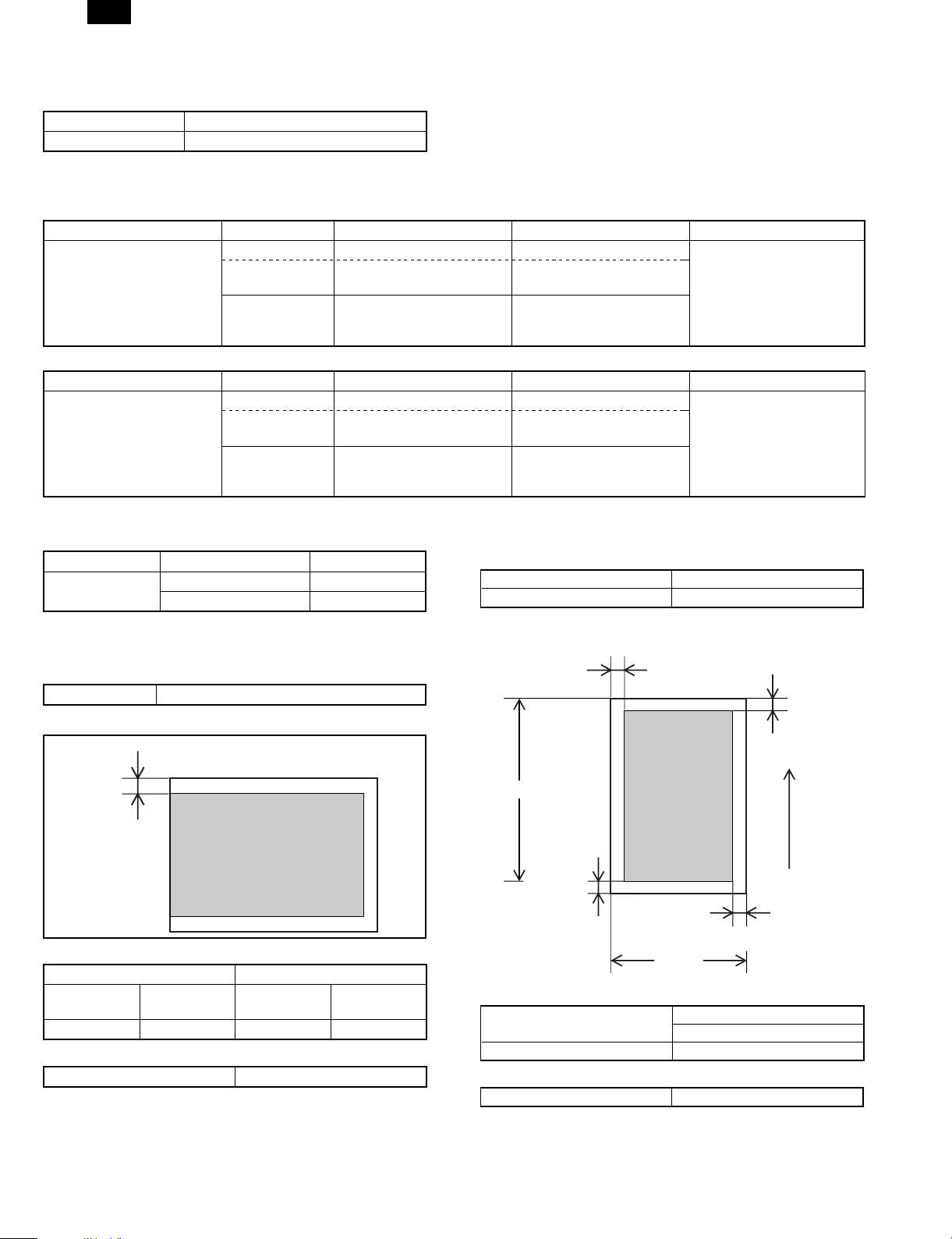
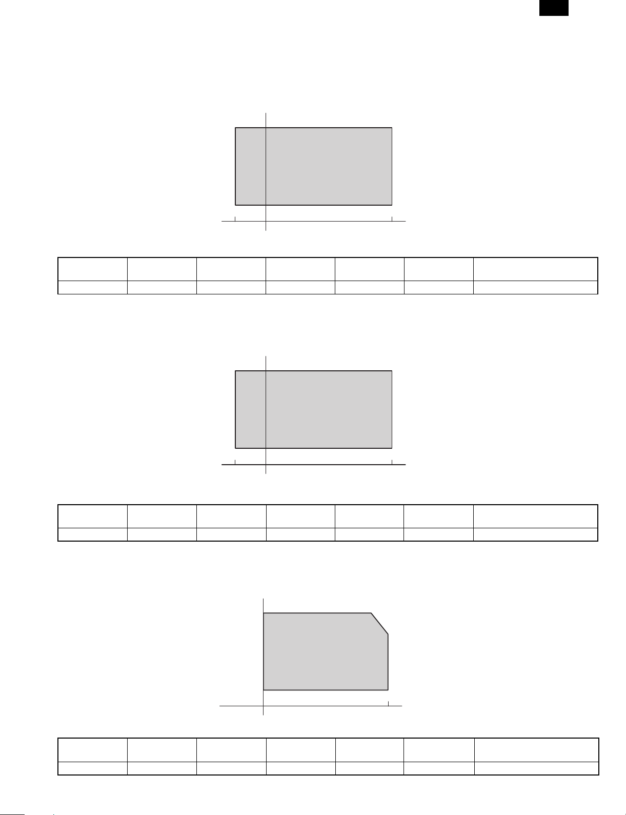
(5) Readable area/size
a. Maximum readable size
(210 × 356 mm)
AB system A4
Inch system 8-1/2" × 14"
b. Scanning area
2.0 mm (Std)
3.0 mm (Max)
(Top)
Printed image
(printable area)
356 mm
2.5 mm (Std)
5.0 mm (Max)
(Bottom)
216 mm
2.0 mm (Std)
3.0 mm (Max)
(6) Scanning speed
Copy ratio
100% 50 mm/sec.
Scanning
Speed
(7) Light source (Lamp)
Power voltage AC 800 V (rms) 48 kHz
1 ~ 5.0 mm
Paper
transfer
direction
2 – 13
Page 19
FO-3800M
(8) Scanning sensor
Type Reduction optical image sensor (CCD)
Monochrome
D. Scanner (Exposure) section
(1) Type
(2) Resolution
Main scanning direction Sub scanning direction
600 dpi 600 dpi
(3) Gradient
2 steps
(4) Details of Laser unit
Revolution 11,811 rpm
Number of mirrors 6
Laser power 0.35 mw
Laser beam size 75 × 65 µm
Laser wave length 785 nm
E. Imaging process section
(1) Imaging speed
50 mm/sec.
(2) Photoconductor (Drum)
Type OPC (φ 24 mm)
Life time 20,000 sheets
(3) Toner
Type Developer cartridge color: black
Capacity/Life time 3,000 sheets (1,500 sheets with initially
installed cartridge) (A4 5% cover ratio)
(4) Charging
Method Brush charging method
Voltage DC-850 V AC 600 V (P-P)
(5) Transfer
Method Transfer roller method
Voltage DC+3.5 kV AC 600 V (P-P)
(6) Exposure
Method Semiconductor laser method
(7) Develop
Method Mono component non-magnetic method
Voltage –310 V
(8) Separation
Method Separation charger type/method
(9) Discharge (Japan only)
Method Discharge brush type
(10) Cleaning
Method By developing roller
Voltage +200 V
F. Fusing
(1)
Method Quick heat-up with pressure roller method
(2) Lamp
Type
Fluorescent
lamp
Main unit
power supply
100/120/230 V 100/120/230 V 500 W
Voltage
Power
consumption
(3) Fusing temperature
Ready mode/
Print mode
160°C 80°C 155°C
Power save mode
Print mode (after
20th sheet in the
multi print mode)
(4) Heat roller
Type Teflon coated roller
(5) Pressure roller
Type Silicone rubber roller
(6) Separation method
Forced separation by separation pawl
G. Power drive
Stepping motor (Main motor)
H. Engine control MCU (PCU)
Processor CPU (H8S2350FP)
ASIC (HG73C025FD)
I. FAX control
Processor ASIC (LZ9FH19)
CPU (FX164)
Controller (FX200)
ASIC (SG46533N)
J. Memory
Type Capacity Contents Location
ROM
(EPROM)
DRAM 16 M bit × 3 Copy image data MCU (PCU) PWB
EEPROM 2 K bit Control data MCU (PCU) PWB
SRAM 32 K bytes × 2 Line image data MCU (PCU) PWB
RAM 265 K bit × 2 Work memory MCU (PCU) PWB
DRAM
SRAM 256 K M bit × 2 Line image data FAX control PWB
ROM 8 M bit Program FAX control PWB
2 M bit Program MCU (PCU) PWB
16 M bit × 3
Image data/for
Work RAM
FAX control PWB
K. Interface
Type Items Operating system
Protocol Peppy/Nibble/ECP
IEEE1284P
Data transfer speed 3 Mbit/sec (Max)
Connector type —
L. Power supply
Type
DC power
supply
High voltage
power supply
Voltage Current Notes
+24 V
+12 V
+5 V
+3.3 V
DC –310 V (+200 V)
DC +3.5 KV (AC 600 V P-P)
DC –850 V (AC 600 V P-P)
Output
2.0 A
0.13 A
1.1 A
0.25 A
—
2 – 14
Page 20
FO-3800M
M. Operating voltage/power consumption
Power consumption
Ready
mode
Power
shutdown
mode
Average
(during
printing)
Sub-
sidiaries
—
—
Power
supply
voltage/
frequency
120V
50/60Hz
220–240V
50/60Hz
Power
save
mode
29 Wh/h 55 Wh/h 17 Wh/h 171 Wh/h 600 W
35 Wh/h 64 Wh/h 18 Wh/h 175 Wh/h 600 W
(Within Rated voltage ± 10% and Rated frequency ± 2%)
N. Safety/environmental standard
(1) Safety/environmental standard
Item Standard name Country
Safety standard SEMKO Sweden
NEMKO Norway
DEKRA (GS MARK) Germany
BSI U.K
CUL UL USA/Canada
FDA USA
Radio wave noise
standard
Energy standard ENERGY STAR World wide
Environmental
standard
(2) Ozon level
Very low (unmeasurable level)
(3) Noise level
Noise mode
Sound power
level
Sound
pressure level
CE MARK Europe
C-TICK Australia
FCC USA/CANADA
(Printer only)
——
Individual
Operating
mode
Ready mode
66 40 0 dB
54.8 dB — 0 dB
Max.
Power
shut-down
mode
(3) Storage conditions (packed in the packing material)
Humidity
RH
90%
10%
–10˚C 50˚C
Humidity
RH
90%
10%
–10˚C 40˚C
Machine
40˚C, 90%
50˚C, 60%
Temperature
Supply
40˚C, 90%
Temperature
(4) Transport condition (packed in the packing material)
Humidity
RH
90%
15%
Machine
30˚C, 90%
40˚C, 60%
O. Ambient conditions
(1) Occupied area
Main unit 460 × 650 mm (18.2 × 29.53 in.)
(2) Operating conditions
Humidity
RH
85%
20%
10˚C 35˚C
Temperature
30˚C, 85%
35˚C, 60%
Humidity
RH
90%
10%
(5) Atmospheric pressure
595 mmHg or above
(6) Standard condition
20 to 25°C 65±5% RH, Rating for different countries
2 – 15
−25˚C 40˚C
Temperature
Supply
40˚C, 90%
−10˚C 40˚C
Temperature
Page 21
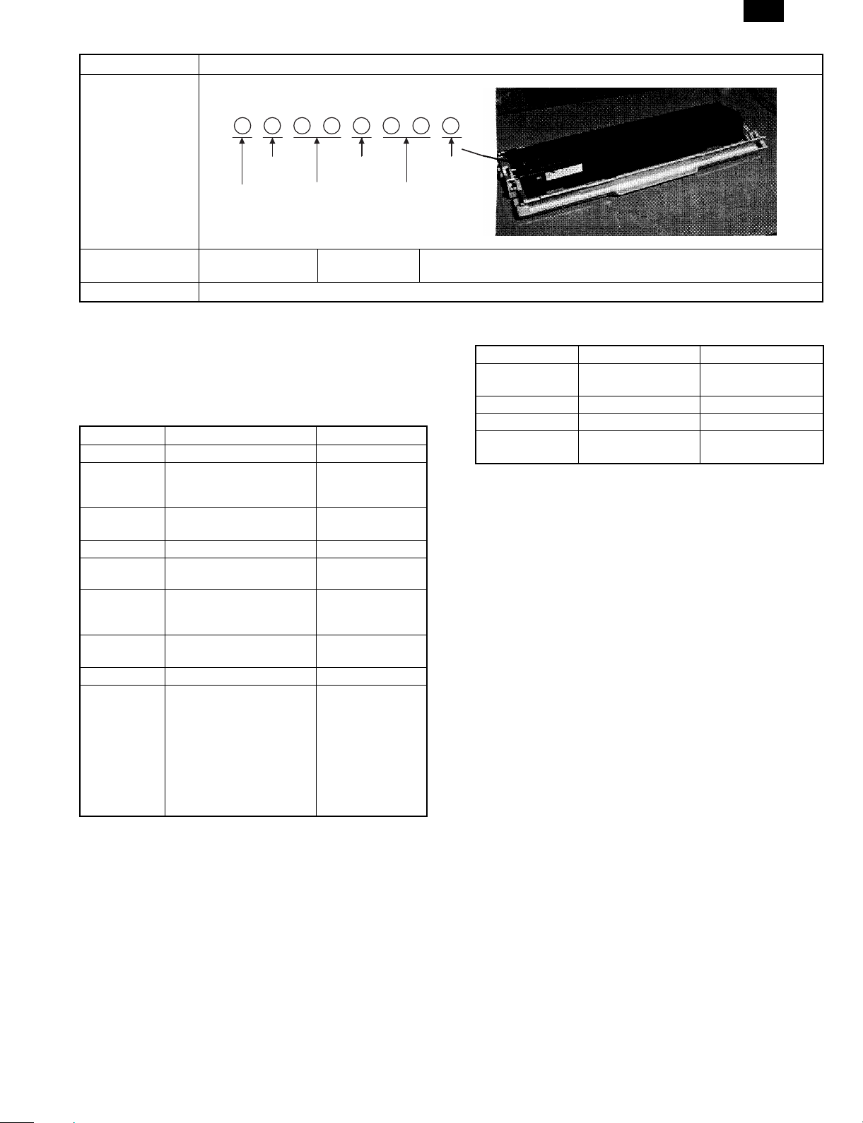
[3] CONSUMABLE PARTS
1. Conf igu rati on
FO-3800M
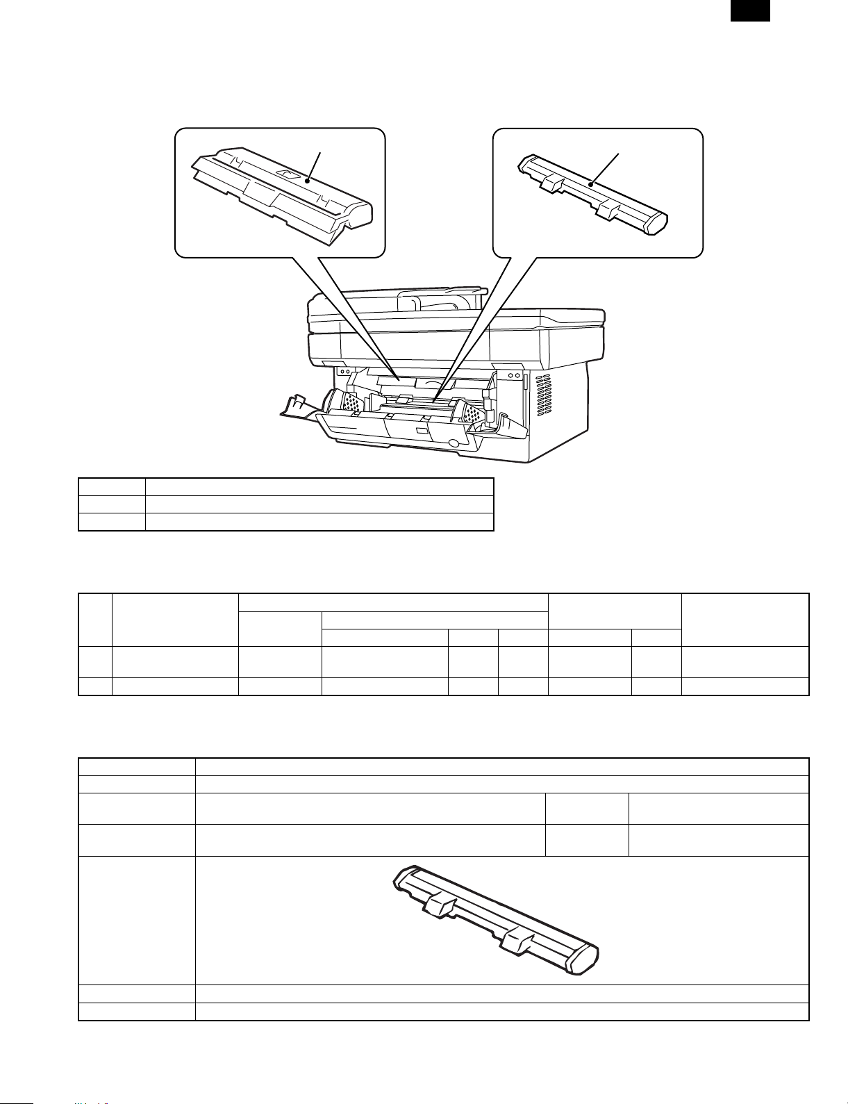
2. Developer cartridge
No. Part name (Item)
1 Photoconductor cartridge
2 Developer cartridge
1. Photoconductor cartridge
2. List
A. Consumable parts for exclusive use
(Single form)
No. Part name (Item)
1 Photoconductor
cartridge
2 Developer cartridge FO-29ND Developer cartridge 1 3K 10
Model name
FO-29DR Photoconductor
Parts item Q’ty Life Model name Q’ty
cartridge
Content
1 20K 10
(Compound form)
3. Detail s
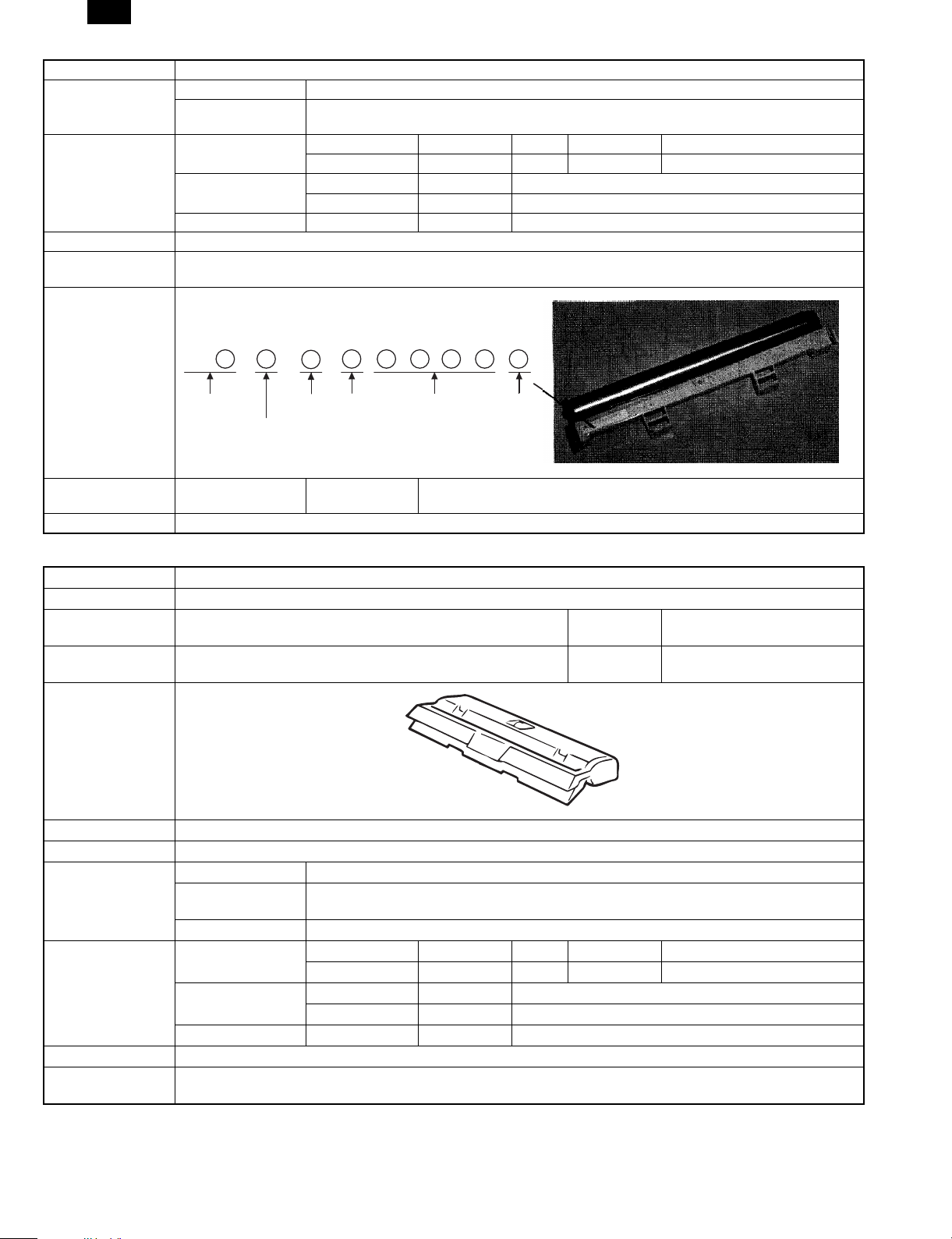
(1) Photoconductor drum
Item Specifications/Descriptions
Part name Photoconductor cartridge
Model name
(Single unit)
Model name
(Compound form)
Photo (Picture)
FO-29DR Quantity 1
—
Quantity 10
Note
Type (Kind) OPC
Form Cartridge
3 – 1
Page 22
FO-3800M
Item Specifications/Descriptions
Life Print quantity 20K
Effective use period 36 months from production when sealed, or 20 months when unsealed. (Shorter one, max. 36
months)
Weight/Capacity/
Quantity
Weight Single unit Weight (g/kg) 241 g Weight (lbs)
Compound form Wright (g/kg) Weight (lbs)
Quantity Single unit
Compound form
Capacity (Litter)
Applied model AL-800/840
Compatibility
information
Product No. content
Ver.
Version
Production year
(End digit)
Fixed to 1. Form
Serial No. in each
production month
Production
month
0: October
X: November
Y: December
Guarantee period (Month) 24 Counted from the production month. Stored under storage environment
conditions (sealed).
Note
(2) Developer cartridge
Item Specifications/Descriptions
Part name Developer cartridge
Model name
(Single unit)
Model name
(Compound form)
Photo (Picture)
Type (Kind) Mono-component toner
Form Cartridge
Life Print quantity 3K (A4, 5% cover ratio)
Weight/Capacity/
Quantity
Applied model FO-3800M
Compatibility
information
FO-29ND Quantity 1
—
Quantity 10
Effective use period 24 months from the production month when sealed, or 12 months when unsealed. (Shorter one,
max. 24 months)
Others
Weight Single unit Weight (g/kg) 473 g Weight (lbs)
Compound form Wright (g/kg) Weight (lbs)
Quantity Single unit
Compound form
Capacity 90 g
3 – 2
Page 23
Item Specifications/Descriptions
Product No. content
FO-3800M
Production
place
Production year
(End digit)
Guarantee period (Month) 24 Counted from the production month. Stored under the storage environment
Note * Replace when print density becomes low.
Destination
form
Version
Production
day
4. Paper specifications
To assure print quality and normal paper handling, the following
specifications of paper should be satisfied.
(1) Paper
Standard and Applicable Paper
Item Standard paper Applicable paper
Weight 60 – 90 g/m
Smoothness face; ≥ 20 s
back; ≥ 20 s
(BEKK method)
Porosity ≥ 7 s
(BEKK method)
Opacity ≥ 77% same as left
Surface
resistivity
Stiffness vertical; ≥ 17 cm
Moisture
content
Thickness 75 µm – 110 µm same as left
Dimension B5 (182 ± 1 × 257 ± 1mm)
1 × 10¹⁰ – 5 × 10
(20 ± 1°C
horizontal; ≥ 13 cm
(CLARK method)
4.5% – 7.0% same as left
B6 (128 ± 1 × 182 ± 1mm)
A4 (210 ± 1 × 297 ± 1mm)
A5 (148 ± 1 × 210 ± 1mm)
A6 (105 ± 1 × 148 ± 1mm)
8.5" ± 5/128 × 14" ± 5/128"
8.5" ± 5/128 × 11" ± 5/128"
5.5" ± 5/128 × 8.5" ± 5/128"
8.5" ± 5/128 × 13" ± 5/128"
(Paper Types That Should Not be Used)
Paper that has any of the following should not be used for printing.
2
10
60 – 120 g/m
face; ≥ 20 s
back; ≥ 18 s
(BEKK method)
same as left
65 ± 2% RH)
same as left
same as left
Production
month
0: October
X: November
Y: December
conditions (sealed).
2
(2) Envelope
Size Dimensions Weight
International DL 110 × 220 mm 60 g/m2 (16 lbs.) to
90 g/m2 (24 lbs.)
International C5 162 × 229 mm Same as above
Monarch 3-7/8" × 7-1/2" Same as above
Commercial 10
(business)
4-1/8" × 9-1/2"
(104.78 × 241.3 mm)
Same as above
Envelopes
Do not use envelopes which have any of the following.
• Metal tabs, snaps, strings, perforations, windows or holes
• Open flaps on which adhesive is exposed
• Glossy surfaces
• A particularly rough texture or embossing
• Envelopes made from recycled paper
• Envelopes that are not flat due to damage, folds or bending, or
which are not straight with square corners
• Envelopes which are curled
• Two or more flaps
• Labels that have already been attached
• Flaps that have not been folded
• Creases or folds on the leading edge
• Adhesive that sticks without moisture when pressed closed
• Envelopes that stick together due to exposed adhesive
• Envelopes that have already been printed on in a laser printer
• Envelopes that expand or shrink without fine creases
• Envelopes which are inflated with air
(3) OHP film
A4 (210 × 297 mm) Letter size (8.5" × 11")
• Paper with special coating on the surface
• Paper with particularly rough or smooth surface
• Paper which has been glued together and which could become
separated.
• Paper with tears, folds, embossing, dryness, moisture or curl
• Paper with metal tabs or clips
• Paper with holes, windows or perforations
• Paper which has been pre-printed using a laser printer or
photocopier
(Note) Before printing, try one of the pieces of paper to be used and
confirm that it can be printed successfully.
(Values at 20 ± 1°C, 65 ± 2% RH)
3 – 3
Page 24
FO-3800M
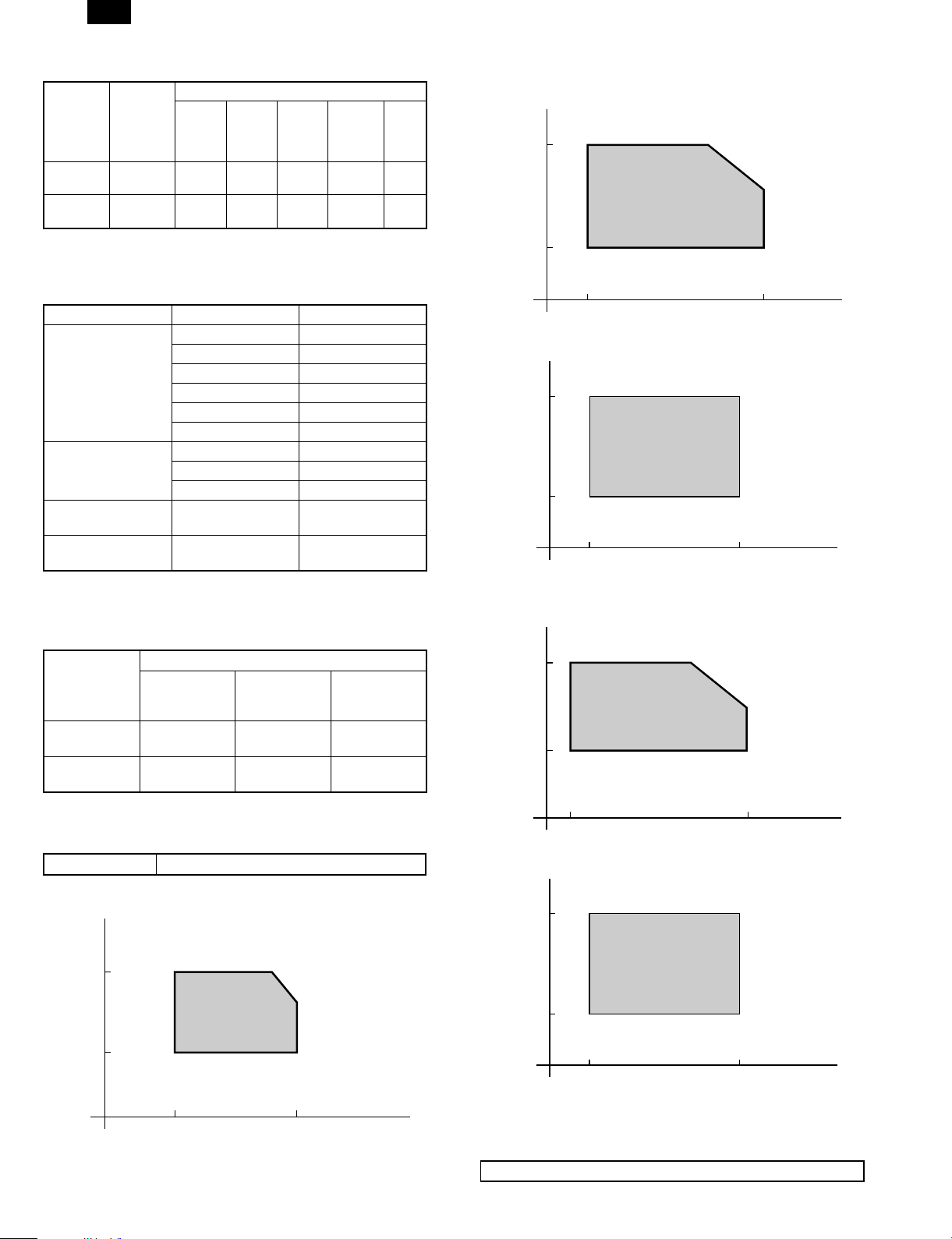
5. Standard density sample
The ratio of the image area for the total area of paper is 5%.
The life of every consumable part is based on this ratio.
Standard density sample
3 – 4
Page 25
6. Environmental conditio ns
(1) Transit environment (sealed)
Max. change: Temperature 15°C/hour, Relative humidity 15%RH/hour, without dew
Humidity
RH
FO-3800M
90%
10%
-10°C 40°C
Temperature
Temperature
(min)
–10°C 10% 40°C 90%
Humidity
(min)
Temperature
(mid)
Humidity
(mid)
Temperature
(max)
(2) Storage environment (sealed)
Max. change: Temperature 15°C/hour, Relative humidity 15%RH/hour, without dew
Humidity
RH
90%
40°C, 90%
Humidity
(max)
40°C, 90%
Period
10%
-20°C 4 0°C
Temperature
Temperature
(min)
–10°C 10% 40°C 90%
Humidity
(min)
Temperature
(mid)
Humidity
(mid)
Temperature
(max)
(Unsealed condition)
Humidity
RH
30°C, 90%
90%
35°C, 60%
10%
0°C 35°C
Temperature
Temperature
(min)
0°C 10% 30°C 60% 35°C 90%
Humidity
(min)
Temperature
(mid)
Humidity
(mid)
Temperature
(max)
Humidity
(max)
Humidity
(max)
Period
Period
3 – 5
Page 26
FO-3800M
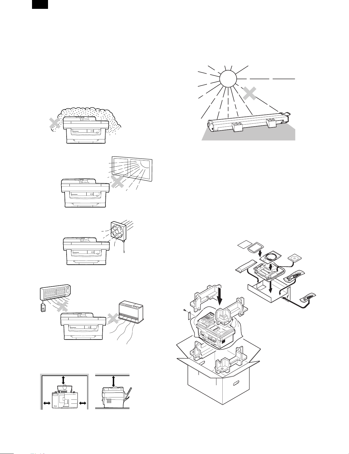
[4] SET UP
1. Installing conditions
Improper installation may damage the copier. Please note the following during initial installation and whenever the copier is moved.
CAUTION: If the copier is moved from a cool place to a warm place,
condensation may form inside the copier. Operation in
this condition will cause poor copy quality and malfunctions. Leave the copier at room temperature for at least 2
hours before use.
Do not install your copier in areas that are:
• damp, humid, or very dusty
• exposed to direct sunlight
CAUTIONS ON HANDLING
Be careful in handling the copier as follows to maintain the performance of this copier.
Do not expose the drum cartridge to direct sunlight.
Doing so will damage the surface (green portion) of the drum
cartridge, causing smudges on copies.
Store spare supplies such as drum cartridges and TD
cartridges in a dark place without removing from the
package before use.
If they are exposed to direct sunlight, smudges on copies may result.
Do not touch the surface (green portion) of the drum
cartridge.
Doing so will damage the surface of the cartridge, causing smudges
on copies.
• poorly ventilated
• subject to extreme temperature or humidity changes, e.g., near an
air conditioner or heater.
Be sure to allow the required space around the machine
for servicing and proper ventilation.
8" (20cm) 8" (20cm)
2. Unpa ckin g
A. Packing list
Open the carton and check if the following components and accessories are included.
4"
(10cm)
4"
(10cm)
4 – 1
Page 27
FO-3800M
Accessories list
Model FO-3800M
Tray (Universal) Included
Drum cartridge Installed
TD cartridge (1.5K) Included
Original cover Included
AC power cord Included UL, CSA PLG
Printer cable IEEE1284 Included
USB N/A
Phone cable Included
Driver soft CD-ROM
Operation manual Copier Included (SEC*)
Printer Included (SEC*)
FAX Included
Warranty card (Registration card) Included (SEC*) in manual
MSDS sheets Included
POP label N/A
Dust cover N/A
User card (Aiyousya card) N/A
Digital logo N/A
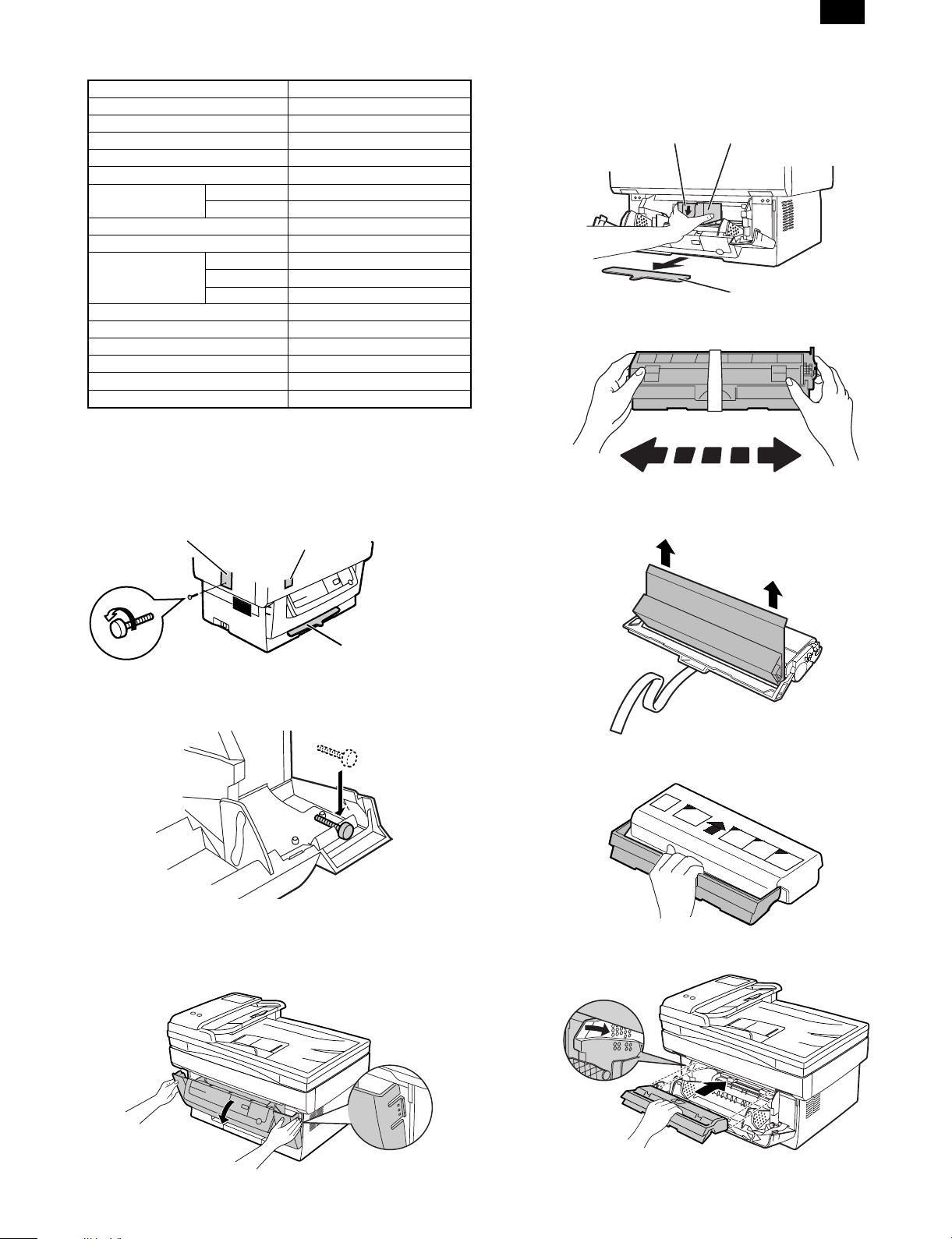
B. Releasing lock
REMOVING PROTECTIVE PACKING MATERIALS
1) Remove tape (a).
2) Turn and remove the lock screw in the arrow direction.
3) Remove the protective material (b).
(a)
(b)
2) Remove the protective material (c), and slowly pull the protective
sheet (d) and protective material (e) together toward you to
remove. Be careful not to break the protective sheet (d) midway
and not to remain torn part inside the machine.
(d)
(e)
(c)
3) Remove the TD cartridge from the bag. Hold the cartridge on both
sides and shake it horizontally four or five times.
CAUTION: Be sure to remove the protective paper from the drum
4) Remove the protective tape and then the protective cover.
cartridge before installing the TD cartridge.
Do not remove with
the front cover closed.
Keep the fixing screw inside the front cover.
Store the lock screw at the right side inside the front cover.
3. Parts and consumable parts setup
(1) Developer cartridge
1) Push gently on both sides of the front cover to open the cover.
5) Hold the handle of the TD cartridge so that the stamped marking
on top of the cartridge are facing upward.
6) Gently insert the TD cartridge into the copier along the guides in
the direction indicated by the arrow.
4 – 2
Align the projections on both sides with the guides.
Page 28
FO-3800M
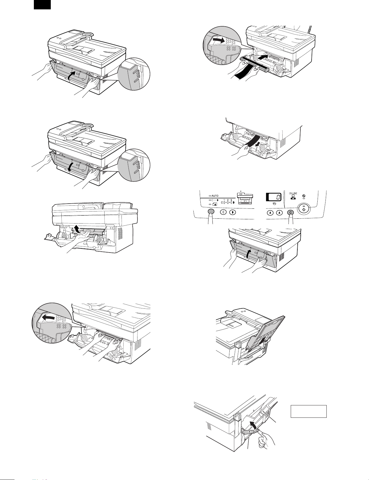
7) Close the front cover.
(2) Photoconductor cartridge
1) Gently press the both sides of the front cover and open it.
6) Remove the black protective sheet from the photoconductor
cartridge.
CAUTION: If the black protective sheet is pulled forcibly, it may be
broken, Be careful not to break the sheet and slowly
remove it.
7) Install the developer cartridge.
8) Turn on the power switch. While pressing the copy mode select
key and the clear key, open and close the operation panel section.
(The photoconductor counter is reset by the above operation.)
2) Slowly remove the developer cartridge from the copier.
3) Hold two knobs of the photoconductor cartridge with your fingers,
and slowly pull out it.
WARNING: The fusing section is heated to a high temperature.
When removing the photoconductor cartridge, be careful
not to touch the fusing section to avoid a burn.
CAUTION: Dispose the photoconductor cartridge as an incombus -
tible.
4) Remove a new photoconductor cartridge from the bag.
CAUTION: • A black protective sheet is attached to a new
photoconductor cartridge in order to protect the
cartridge from light. Install the cartridge in the copier
with this black sheet attached to it. If it is removed, the
cartridge surface (green section) may be damaged.
• Keep the photoconductor cartridge in a clean place. If
it is stored in a dusty place, the cartridge surface
(green section) may be damaged to cause a dirt on
print paper.
5) Hold the two knobs of the photoconductor cartridge with your
fingers, and slowly insert the projections on the both ends of the
cartridge into the machine along the guides in the arrow direction.
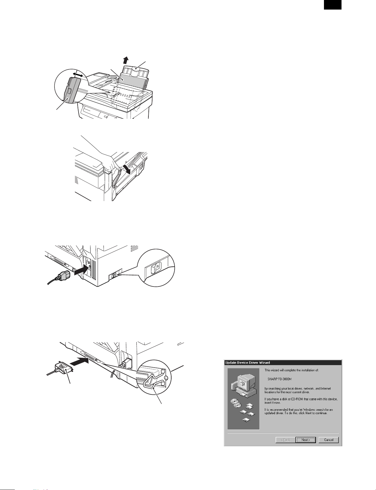
(3) Paper tray
1) Hold the paper tray so that the paper guide of the paper tray is
facing front and then insert the paper tray into the copier’s paper
tray slots.
2) Pull the paper release lever at the right of the paper tray toward
you.
CAUTION: If the paper is inserted without doing this, paper misfeeds
will occur.
View from the
back of machine
Paper tray
Paper release lever
4 – 3
Page 29
FO-3800M
3) If extra-long paper (such as legal size) is used, raise the paper
support to support the paper. Fan the copy paper and place it into
the paper tray with the side to be printed facing toward you. Position the paper along the right end of the paper tray. Then adjust
the paper guide to the paper width.
Paper support
Side to be printed
Paper guide
4) Make sure the paper release lever is pushed back. The paper will
be clamped by the paper feed roller inside the copier.
4. Cable con ne c ti on
(1) Power cable
Ensure that the power switch of the copier is in the OFF position.
Insert the attached power cord into the power cord socket at the rear
of the copier.
(2) Interface cable
1) Check that the power switches of both the printer and the computer are in the OFF position.
2) Plug the parallel interface cable into one of the printer interface
connectors (whichever connector you want to use). Fasten the two
bail chips at the side of the printer connector to hold the interface
connector in place.
Connecter
5. Installing the printer and TWAIN
(Scann er ) dri ve r sof tw a re
(1) Checking the hardware and software
requirements
You will need the following hardware and software in order to install
the printer driver.
Computer type
IBM PC/AT or compatible computer equipped with ECP modeequivalent bi-directional parallel interface and CD-ROM drive
Windows type
Windows 3.1x, Windows 95, Windows 98, Windows NT 4.0
CPU 486DX 66MHz or better
Physical RAM
Windows 95, Windows 3.1x: 8MB (16MB or more is recommended.)
Windows NT 4.0: 12MB (16MB or more is recommended.)
Windows 98: 16MB (32MB or more is recommended.)
Virtual storage (swap file) 8MB or more
Display 640 x 480 dots (VGA) or better
Hard disk free space 11MB or more
CAUTION: The printer driver included in this product cannot be used
under Windows NT 3.5x, OS/2, pure MS-DOS and other
operating systems which are not described above.
(2) Installing the printer driver
The software for your machine is provided on the CD-ROM which
was packed with your machine.
Before installing the printer driver, be sure to check the following
items.
• Is the machine connected properly to the computer?
• Does the machine have paper?
• Is there another GDI printer driver or Windows Printing System
printer driver already installed? If installed, change the printer port
setting.
a. Windows 95/Windows NT 4.0:
1) Load paper into the paper tray of the machine. For instructions on
loading paper, see the section LOADING COPY PAPER in the
copier operation manual.
2) Turn on the machine.
3) Turn on your computer and start Windows.
NOTE: Before installing the printer driver, be sure to close all other
applications which may be open.
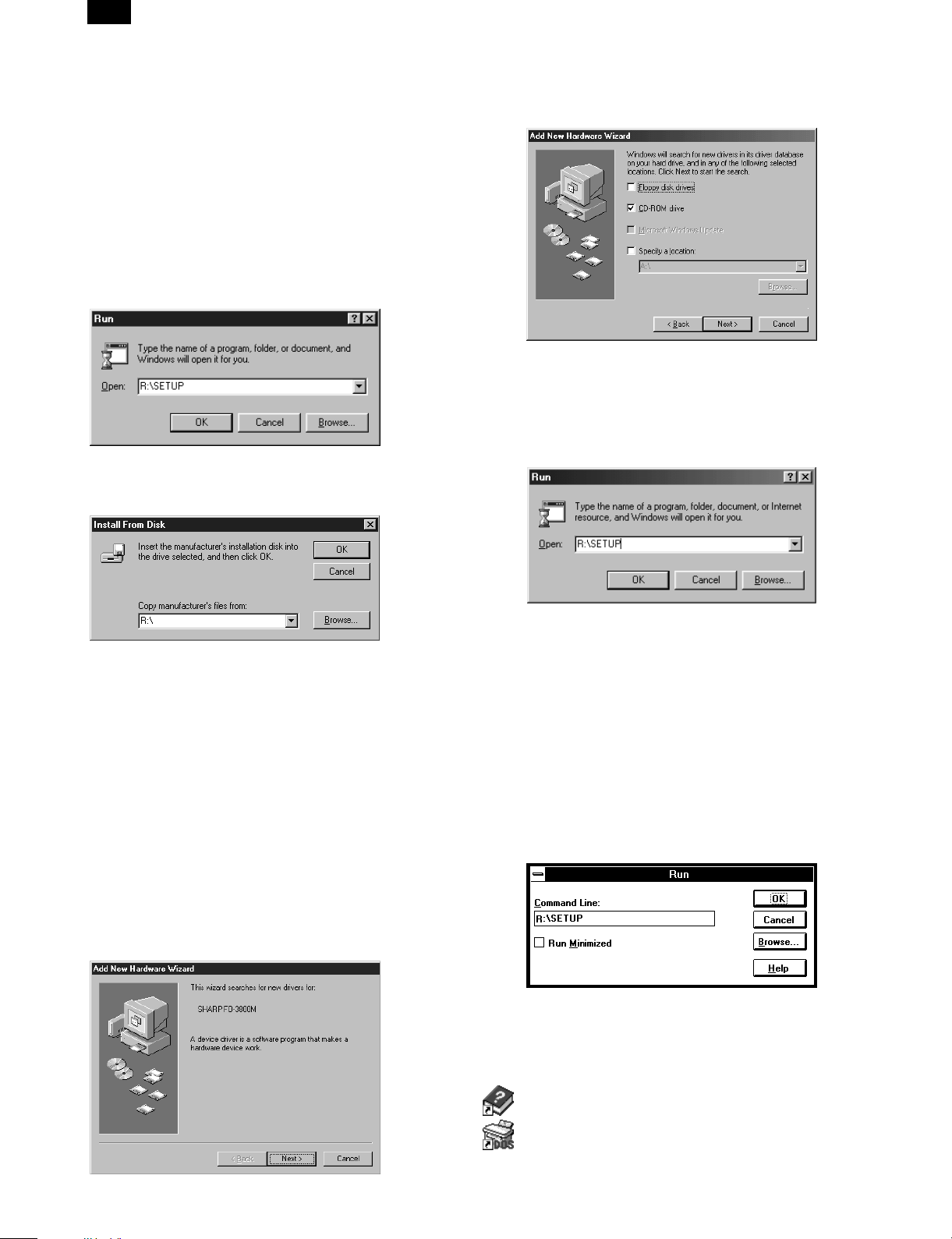
4) When using Windows 95 on a personal computer with plug &
play*, the "Update Device Driver Wizard" window will appear. Insert the installation CD-ROM into the CD-ROM drive. Click the
Next button and follow the on-screen instructions. If the "Copying
Files" window appears during this operation, enter R:\ (if the CDROM is designated as drive R), click the OK button and follow the
on-screen instructions.
Cable
Interface connector
Bail clip
3) Plug the other end of the cable into the parallel interface connector of your computer.
CAUTION: The printer sends and receives data bi-directionally and
at high speed. Some switch boxes and pass-through
devices cannot support high-speed, bi-directional transfer of data, and using them may cause printing errors.
CAUTION: Some printer selectors (which allows to use two or more
computers and printers by selection) are not compatible
to this machine.
• If you use Windows 95 and the "New Hardware Found" window
will appear, select Driver from Disk Provided by Hardware
Manufacturer and then click the OK button. Proceed to step 6.
4 – 4
Page 30
FO-3800M
• If you use Windows 95 and the screen shown above or the
"New Hardware Found" window does not appear, proceed to
step 5.
• If you use Windows NT 4.0, proceed to step 5.
Plug & Play
∗
This feature is effective if both the computer and peripheral
equipment are equipped with an IEEE 1284 compliant parallel
interface.
NOTE: The screen displayed depends on the version of Windows
you are using.
5) Insert the installation CD-ROM into the CD-ROM drive.
Click the Start button and select Run. When the screen shown
below appears, type R:\SETUP (if the CD-ROM is designated as
drive R) and click the OK button. Follow the on-screen instructions.
6) The "Install From Disk" window will appear. Insert the installation
CD-ROM into the CD-ROM drive. Type R:\ (if the CD-ROM is
designated as drive R) and click the OK button. Follow the onscreen instructions.
5) Select Search for the best driver for your device and click the Next
button.
6) Insert the installation CD-ROM into the CD-ROM drive. Select
CD-ROM drive and click the Next button.
7) Windows driver file search will find the device "SHARP FO3800M". Click the Next button and follow the on-screen instructions.
8) Insert the installation CD-ROM into the CD-ROM drive. Click the
Start button and select Run. When the window shown below appears, type R:\SETUP (if the CD-ROM is designated as drive R)
and click the OK button. Follow the on-screen instructions.
NOTE: If you have any problem with the test print, see
TROUBLESHOOTING on page 20 and check the symptoms
and solutions. Print the test page again after removing the
problem.
b. Windows 98:
1) Load paper into the paper tray of the machine. For instructions on
loading paper, see the section LOADING COPY PAPER in the
copier operation manual.
2) Turn on the machine.
3) Turn on your computer and start Windows.
NOTE: Before installing the printer driver, be sure to close all other
applications which may be open.
4) When using Windows 98 on a personal computer with plug &
play*, the "Add New Hardware Wizard" window will appear. Click
the Next button and follow the on-screen instructions.
• If the "Add New Hardware Wizard" window does not appear,
proceed to step 8.
Plug & Play: For plug & play information, see page 6.
∗
NOTE: If you have any problem with the test print, see
TROUBLESHOOTING on page 20.
c. Windows 3.1x:
1) Load paper into the paper tray of the machine. For instructions on
loading paper, see the section LOADING COPY PAPER in the
copier operation manual.
2) Turn on the machine and then start Windows on your computer.
NOTE: Before installing the printer driver, be sure to close all other
applications which may be open.
3) Insert the installation CD-ROM into the CD-ROM drive.
4) Choose File from the Menu bar in Program Manager, and then
choose the Run... command.
5) Type R:\SETUP (if the CD-ROM is designated as drive R) in the
command line box and then click the OK button.
6) Follow the on-screen instructions.
d. "SHARP FO-3800M" printer driver group
When the printer driver is installed, the SHARP FO-3800M printer
driver group will be created. This group allows the following functions
to be executed.
DOS Emulation HELP
4 – 5
DOS Emulation Setup
Page 31

FO-3800M
Readme
The latest information on the printer driver and the TWAIN
driver is included in this note. Read the Readme first.
Status Monitor HELP
Status Monitor
The printer state and information on current printing are displayed on the status monitor window. When printing starts,
the status monitor screen will appear on the computer display.
Uninstall FO-3800M
The printer driver and the TWAIN driver can be uninstalled.
If the drivers are uninstalled, printing and scanning cannot be
performed on the machine.
NOTE: • Be sure to read "Readme" found in the printer driver group
before starting to print or scan from application programs.
• If you uninstall the printer driver, the TWAIN driver is
uninstalled at the same time.
(3) Using other installed drivers
If you use another GDI printer or Windows Printing Systems printer,
including the SHARP AL-800 series and AL-1000 series, interference
between printers may occur and printing may not be performed
properly.
To use another GDI printer or a Windows Printing System printer, you
must change the port setting of the printer driver using the following
procedure.
NOTE: If another printer does not operate properly when the FO-
3800M printer driver is set to "FILE", uninstall the FO-3800M
printer driver.
To uninstall the driver, see UNINSTALLING PRINTER
DRIVER on page 23.
If after uninstalling the FO-3800M printer driver, the printer
still does not operate properly, reinstall the printer driver you
are using.
a. Windows 95/Windows 98/Windows NT 4.0:
1) Click the Start button.
2) Select Settings and then click Printers.
3) Right-click the FO-3800M icon in the printer dialog box and then
click Properties.
NOTE: For this description, it is assumed that the mouse is con-
figured for right hand operation.
4) Click the Details tab (Ports tab – on Windows NT4.0) in the
Properties dialog box, select FILE: in the Print to the following port
list box, and click the OK button.
5) Right-click the icon of the printer to be used and click Properties.
6) Click the Details tab (Ports tab – on Windows NT4.0) in the
Properties window, select LPT1 (or the currently used port), and
click the OK button.
NOTE: To use the FO-3800M again, perform the same procedure
but select the port to be used (for example, LPT1) in step 4.
b. Windows 3.1x:
1) Double-click the Control Panel icon in the Main window of Program Manager.
2) Double-click the Printers icon. The Printers window will then open.
3) Select FO-3800M, and then click the Connect button.
4) Select File from the list of options in the Ports window, and then
click the OK button.
5) Select the new printer you would like to use from the list in the
Installed Printers window, and then click the Connect button.
6) Select the printer port to use for the new printer, and then click the
OK button.
7) Click the Set As Default Printer button, and then click the Close
button.
NOTE: To use the FO-3800M again, perform the same procedure
but select the port to be used (for example, LPT1) in step 4.
(4) Uninstalling drivers
If the printer driver and TWAIN driver are not installed correctly or if
you no longer use this machine, uninstall the printer driver and
TWAIN driver from your computer using the following procedure.
1) If using Windows 95/Windows 98/Windows NT 4.0, click Start,
Program, SHARP FO-3800M, and Uninstall FO-3800M.
If using Windows 3.1x, double-click the SHARP FO-3800M icon in
Program Manager and double-click the Uninstall FO-3800M icon.
2) When the "Confirm File Deletion" window appears, click the Yes
button.
3) When the "Remove Programs From Your Computer" window appears, click the OK button.
NOTE: The printer driver and the TWAIN driver are uninstalled at the
same time.
6. Setup FAX section
A. Connecting the Telephone Line Cord
Plug one end of the telephone line cord into the jack on the machine
marked "LINE."
Plug the other side into a standard (RJ11C) single-line telephone wall
jack. Be sure not to plug this telephone line cord into the "TEL" jack.
The "TEL jack" is used to attach an extension telephone or answering
machine to the machine.
Note: If your area experiences a high incidence of lightning or power
surges, we recommend that you install surge protectors for the
power and telephone lines.
LINE
TEL
B. Connecting Other Devices
If desired, an answering machine or external telephone can be connected to the machine through the telephone jack, labeled TEL, on
the rear of the machine.
• Connecting an answering machine to the machine allows you to
receive both voice and fax messages when you are out. To use
this feature, first change the outgoing message of your answering
machine, and then set the reception mode of the machine to
"A.M." (Answering Machine mode) when you go out.
Note: If you are using distinctive ringing with an answering machine,
you do not need to follow the procedure described below.
(Please note that when distinctive ringing is used, the answering machine must be distinctive ring compatible.)
The outgoing message of your answering machine should be
changed to inform callers who want to send a fax to press their FAX
START key.
Comments:
1. It is advisable to keep the length of the message under 10
seconds. If it is too long, you may have difficulty receiving faxes
sent by automatic dialing.
2. Your callers can even leave a voice message and send a fax
message on the same call. Modify your outgoing message to
explain that this can be done by pressing their FAX START key
after leaving their voice message.
4 – 6
Page 32

FO-3800M
• You can connect an extension phone to the machine to make and
receive calls like any other extension phone on your line. Even if
you pick up the extension phone and hear a fax tone, the machine
will automatically cut in and take over the line. Note, however, if
you also have a PC modem on the same line, you must turn on the
Remote Reception function, and deactivate the Fax Signal Receive
function.
Note: The Remote Reception function is initially set to "ON".
(1) Using the Machine with an Answering Machine
a. Quiet Detect Time
Quiet Detect Time is the function that enables the machine to be used
along with an answering machine for both phone messages and
faxes. After the answering machine has answered, any duration of
silence longer than a certain threshold time will prompt the machine
to take over the line and prepare to receive a fax. The Quiet Detect
Time can be set from 00 to 10 seconds, following the procedure
below.
Factory setting: 05
Step Press these keys Comments
ENTER
STOP
TUV
to
STOP
“A.M. MODE” will appear in the
display.
“QUIET DETECT TIME” will appear in
the display.
Enter the Quiet Detect Time in
seconds, from 00 to 10.
(Setting “00” turns off Quiet Detect
Time)
“STORED” will appear in the displa y.
Press the STOP key twice to exit.
1
2
3
4
5
Notes:
FUNCTION
• The machine has been set at the factory for a Quiet Detect Time of
5 seconds, which gives the best performance for most answering
machines. However, you may have to adjust the Quiet Detect Time
depending on your answering machines disconnect time, the time
before the machine disconnects the line after a period of silence. If
your machine has a short disconnect time, you may have to shorten the Quiet Detect Time. However, if the machine is interrupting
callers in the middle of messages, you should set a longer Quiet
Detect Time.
• If there is a pause at the end of your answering machine message,
make sure that the Quiet Detect Time is longer than this pause.
• Setting Quiet Detect Time to 00 turns the function off. However,
the machine will not be able to receive faxes sent using manual
dialing (picking up the receiver, dialing the number, and pressing
the FAX START key when the fax tone is heard).
b. If Quiet Detect Time is not working properly...
With some answering machines, there is simply no Quiet Detect
Time that will allow both reception of faxes and uninterrupted voice
messages. Even in this case, however, you can set up the machine to
receive both phone and fax messages from callers on touch-tone
lines. Follow this procedure:
1. Set the Quiet Detect Time to 00.
2. Using the Remote Reception Number (factory set to 5) to start fax
reception, change your answering machine message to include
the following information. "If you want to send a fax press 5 and
then press the ( ) key twice, after you hear the fax tone press
your FAX START key".
c. Answering Machine Backup
There may be times when the tape on your answering machine becomes full, or when the answering machine itself malfunctions. It is
still possible to receive faxes even under these conditions, however,
by turning on the Auto Receive function. The machine will automatically answer all calls after five rings. To use this function, follow the
procedure below.
Factory setting: 2 (OFF)
Step Press these keys Comments
ABC
STOP
TUV
ABC
or
STOP
“A.M. MODE” will appear in the
display.
“SELECT AUTO RECEIVE” will
appear in the display.
Press 1 to turn Auto Receive on, or
2 to turn it off.
Press the STOP key twice to exit.
FUNCTION
1
2
3
4
Note: If you are using Auto Receive, make sure that your answering
machine is set to answer on four rings or less. Otherwise, the
machine will take over all calls, preventing callers from leaving
voice messages.
(2) Setting Up the Machine for Use with a PC Modem
The machine is set to automatically begin reception if you pick up
from an extension telephone and the machine detects a fax tone.
However, if you are using a modem on the same line, you must
deactivate this function: otherwise the machine will mistakenly attempt to receive the transmission from your computer. To turn off the
Fax Signal Receive function, follow the procedure below.
Note: If you turn off the Fax Signal Receive function, be sure to
activate the Remote Reception function.
Factory setting: 1 (ON)
Step Press these keys Comments
FUNCTION
1
2
3
4
STOP
GHI
ABC
ABC
or
STOP
“OPTION SETTING” will appear in the
display.
“FAX SIGNAL RCV.” will appear in the
display.
Press 1 to turn Fax Signal Receive
on, or 2 to turn it off.
Press the STOP key twice to exit.
7. Note for transport
When transporting this machine, follow the following packing procedures before moving.
• To transport this machine, be sure to use the original packing case
and the protective material.
If another packing case is used, the machine may be damaged.
• Be sure to remove the developer cartridge before transport.
1. Turn off the power switch and disconnect the power cord.
2. Remove the interface cable from the machine.
3. Gently press the both sides and open the front cover.
4. Remove the developer cartridge from the machine.
5. Remove paper from the paper feed tray.
6. Remove the paper feed tray from the machine.
7. Return the paper feed tray slowly to the bottom.
8. Attach the fixing screw (which is keep inside the machine) to the
left side of the machine.
9. Close the front cover.
10. Attach the protective material and tapes which were removed
when unpacking.
11. Put the machine in the packing case.
4 – 7
Page 33

[5] EXTERNAL VIEW AND INTERNAL STRUCTURE
1. List
A External, operation parts (1) External, operation parts
(2) Internal operation parts
(3) Operation, display parts
B Internal parts (1) Parts in each section a Operation section
b Paper feed, transport section
c Optical section <1> Scanner (reading) section
d Image process section <1> OPC drum section
e Fusing, paper exit section
f Drive section
g Printer section
h FAX section
i Cross sectional view
C Lock position
D Functional parts (1) Sensor, detector
(2) Switch
(3) Clutch, solenoid
(4) Motor a Drive motor
b Fan (motor)
(5) PWB
(6) Fuse, thermostat
(7) Lamp
(8) Interface (connector)
(9) Belt, wire
(10) Power
(11) Adjustment volume
FO-3800M
<2> Scanner (writing) section
<2> Developing section
<3> Transfer, separation section
2. Cont ent s
A. External, operation parts
(1) External, operation parts
5)
4)
1)
7)
6)
11)
10)
2)
3)
12)
8)
9)
13)
5 – 1
Page 34

FO-3800M
No.
1 SPF unit (Document cover)
2 Front cover Opened when installing or removing the OPC cartridge and
3 Paper exit tray Receives printed paper.
4 Operation panel Allows various setting in the copy mode and test command
5 Document table A document is set to the left corner reference.
6 Paper feed tray Sets print paper.
7 Paper guide Adjusts the paper width.
8 Power switch Turns on/off the main power.
9 Power connector Connects with the AC power cord.
10 Printer interface connector Connects with the host computer. (Parallel interface)
11 Paper release lever Put the lever straight when setting paper to release paper
12 LINE jack Used to connect with the TEL line.
13 TEL jack Used to connect with the external TEL line.
Name Function/Operation
the developer cartridge or removing a paper jam.
operations.
(IEEE-1284)
feed drive. Put the lever down to allow paper feed.
Parts
(2) Internal operation parts
1)
Model Note
Allows connection with two
host computers.
2)
No.
1 Developer cartridge Converts latent electrostatic images into visible
2 OPC cartridge Forms latent electrostatic images. Common Life (20K print)
Name Function/Operation
images (toner images).
Parts
Model Note
Common Life (3K print)
5 – 2
Page 35

(3) Operation, display parts
a. Main body section
1) 2) 3) 4) 5) 6) 7) 8) 9) 10) 11)
No.
1 Copy image mode select
key/Copy image mode
display lamp
2 Copy density adjustment
key/Copy density level
display lamp
3 SPF display lamp Lights up when a document is set on the SPF
4 SPF jam lamp Lights up when a document jam or mis-feed
5 Developer cartridge warning
lamp
OPC cartridge warning lamp Turns on or blinks to show that a consumable
Paper jam warning lamp Turns on or blinks when there is a paper jam.
6 Copy magnification ratio
select key/Copy magnification
ration display lamp
7 Zoom mode display lamp Turns on when the zoom key is used to set the
8 Copy magnification display
key
9 Value, code display LED Displays the value information (copy quantity,
10 On-line lamp Turns on during operation in the printer mode.
11 Pre-heat mode display lamp Blinks in the pre-heat mode.
12 Zoom key Sets the copy magnification ratio in the range of
13 Value setting key Used to input various set values (copy quantity,
14 Clear key Cancels various setting and operations.
15 Start key Starts operations and stores various set data.
Ready lamp Turns on when in print ready state.
Name Function/Operation
Parts
Selects the copy image mode in auto, character,
photo, toner save mode. Displays the copy image
mode.
Selects the copy density. Used to set the power
save mode. Displays the copy density mode
(level).
document feed tray.
occurs in the SPF section.
Turns on or blinks to show that the consumable
part (developer cartridge) must be replaced.
part (developer cartridge, OPC cartridge) or that
there is a paper jam.
Selects the copy magnification ratio.
coy magnification ratio.
Used to display the copy magnification ratio set
by the zoom key on the value display.
copy magnification ratio, etc.) and codes (error
code, test command code and its information).
(Print data is received from the host in the printer
enable state or during printing.)
50% ∼ 200% by the increment of 1%.
test command setting, power save mode setting,
etc.). Used to set the power save mode.
FO-3800M
12) 13) 14) 15)
Model Note
Turns on when there is little toner, and
blinks when there is no toner to
disable printing.
At 19,000 print, the lamp lights up to
show the life is up. At 20,000 print, the
lamp lights up to disable printing.
5 – 3
Page 36

FO-3800M
b. FAX section
Left arrow key ( ) and right arrow key ( )
Press these keys to scroll through a menu. During input
mode, these keys are also sometimes used to move
the cursor.
FUNCTION key
Press this key to
enter function
mode.
Liquid crystal display
Shows various messages during fax
operation and programming.
BOOK SEND key
Press this key to fax a
original from the original
table.
RESOLUTION key
Press this key to
adjust the resolution
before sending faxes.
CONTRAST key
Press this key to adjust
the contrast before
sending faxes.
Rapid keys
Press one of these keys to
dial a fax or telephone
number automatically.
Press Rapid key 20 to start
polling if programmed.
(Note that you must attach
the Rapid key labels.)
FUNCTION
BOOK SEND
RESOLUTION CONTRAST BROADCAST
01 02 03 04 05
06 07 08 09 10
11 12 13 14 15
16 17 18 19 20/POLL
GHI
PQRS
Number keys
Press these keys to dial
numbers, and enter
numbers and letters
during number/name
storing procedures.
/
Press these keys to enter
symbols during the name
storing procedure.
Press the " " key to
change
from pulse dialling to tone
dialling mode.
STOP key
Press this key to stop an operation
before it is completed, or to delete
the number that was last input.
This key is also used to close the
line when manually dialling.
ENTER
AUTO
MANUAL
A.M.
RECEPTION MODE
ABC
DEF
DOCUMENT
MNO
JKL
TUV
FAX STARTSTOP
WXYZ
SPEED/SEARCH
REDIAL/PAUSE
SPEAKER
FAX START key
Press this key to begin
sending a fax or manually
receiving a fax.
ENTER key
Press this key to decide an
item in a menu, or to enter
numbers and letters you
have typed in.
AUTO light
This light indicates that the
machine will answer
machine
automatically.
the
MANUAL light
This light indicates that
machine
must be answered
manually.
the
A.M. light
This light indicates the
answering machine will answer
the line if properly connected.
RECEPTION MODE key
Press this key to select
the mode of reception.
BROADCAST key
Press this key to send
originals to a group of
receiving fax machines.
DOCUMENT key
Press this key to perform a
direct send fax transmission.
SPEED/SEARCH key
Press this key to dial a two
digit Speed Dial number.
During character inputting,
use this key to delete an
incorrect entry.
Also, press this key twice to
search for an automatic
dialling number.
REDIAL/PAUSE key
Press this key to
automatically redial the last
number you dialed. Also,
press this key to insert a
pause when entering
numbers.
SPEAKER key
Press this key to begin
manual dialling. (To close the
line, press the SPEAKER
key again.)
5 – 4
Page 37

B. Internal parts
(1) Parts in each section
a. Operation section
FO-3800M
2)
1)
No.
Name Function/Operation
Parts
1 Operation control PWB Displays various number information and messages.
Outputs the key operation signal.
2 Number display Displays various value information and messages.
b. Paper feed, transport section
1) PE SENSOR
2)
8)
7) PIN SENSOR
3)
4)
5) PUS
6)
Model Note
9) PAPER SIZE SW
10)
11)
4)
6)
13)
12)
19)
8)
12)
19)
13)
14)
15)
17)
16)
16)
18)
5 – 5
Page 38

FO-3800M
No.
1 PE SENSOR PEMP IN Paper empty
2 Paper guide Adjust the paper width.
3 Paper feed tray Sets the print paper. (Capacity:
4 Paper release
5 PUS PUS Paper feed clutch
6 Paper feed
7 PIN SENSOR PIN Paper in detector Photo
8 Paper feed roller Feeds paper.
9 PAPER SIZESWPAPER SIZEINPaper width
10 Paper pressure
11 Paper pressure
12 Paper separator Separates paper in paper feed
13 Paper feed clutch Mechanical
14 Paper feed clutch
15 Paper feed clutch
16 Paper feed clutch
17 Paper feed clutch
18 Paper feed clutch
19 Paper separater
Code Signal name Name Type Function/operation Active condition
detector
lever
solenoid
release lever
detector
plate
spring
lever
joint
sleeve
spring
gear
spring
Parts Note
Photo
transmission
sensor
transmission
sensor
Mechanical
switch (Micro
switch)
spring type
clutch
Detects paper on the paper tray. LOW (0V) when
XXX sheets)
Put this lever straight to set paper
to release paper feed. Put this
lever down to enable paper feed.
Controls (on/off) the main motor
drive for the paper feed roller.
When the paper feed lever is put
straight, this lever releases paper
feed solenoid drive. This lever
reduces stress to the paper feed
roller clutch in removing paper.
Detects whether the fed paper is
transported to the transfer position
or not. By the timing of this
detector signal, the relative
positions of paper and print image
are controlled.
Detects the paper width. This
signal controls the laser beam
radiation area.
Presses paper onto the paper
feed roller.
Presses paper onto the paper
feed roller.
operation.
Controls ON/OFF of the paper
feed roller. (The paper feed roller
is driven by the paper feed clutch
solenoid and the main motor.
Driven by the paper feed clutch
solenoid to control ON/OFF of the
paper feed clutch. Prevents
against reverse rotation of the
paper feed roller.
Links the paper feed roller and the
paper feed roller clutch.
Controls ON/OFF of the paper
feed roller. (The paper feed roller
is driven by the paper feed clutch
solenoid and the main motor.)
Transmits the paper feed clutch
rotation to the paper feed clutch
sleeve.
Transmits the main motor power
to the paper reed roller.
Applies a proper pressure to the
paper separater.
paper is detected.
LOW (0V) when
paper is detected.
LOW (0V) when
the max. width is
detected.
5 – 6
Page 39

c. Optical section
<1> Scanner (reading) section
4) MHPS
10)
11)
8) SL SENSOR
FO-3800M
2)
6) CCD SENSOR
3)
5)
2)
7)
4) MHPS
10) 8) SL SENSOR 7) 6) CCD SENS
9)
1)
11) 9) 5) 3)
Parts
No.
1 Scanner lamp
2 Scanner drive wire Transmits the scanner motor power to
3 Scanner motor Drives the scanner unit.
4 MHPS MHPS Scanner home
5 Lens Transfers the document image to CCD.
6 CCD
7 Scanner lamp Radiates light to the document to allow
8 SL SENSOR PDA/PDK Scanner lamp light
9 No. 1 mirror Leads the document image to CCD.
10 No. 2 mirror Leads the document image to CCD.
11 No. 3 mirror Leads the document image to CCD.
Code
SENSOR
Signal
name
CCD OUT CCD (Image)
Name Type Function/operation Active condition
control PWB
position sensor
sensor
quantity sensor
Drives the scanner lamp. Maintains the
lamp light quantity at a constant level.
the scanner unit.
Photo
transmission
sensor
CCD Scans the document images (photo
Photo diode Detects the scanner lamp light
Detects the scanner home position. By
this signal the image scanning
operation is controlled.
signals) and converts them into
electrical signals.
the CCD to scan the document images.
quantity. This signal is inputted to the
scanner lamp control PWB to control
the scanner lamp drive voltage to
maintain a constant level of light
quantity.
OR
Note
HIGH (5V) when
the home position
is detected.
Digital signal (8Bit)
Analog signal
(0 ∼ 0.5V)
5 – 7
Page 40

FO-3800M
<2> Scanner (writing) section
8)
1) SYNC
2)
3)
7)
4)
6)
5)
No.
Code Signal name Name Type Function/operation Active condition
1 SYNC SYNC IN Laser beam sensor Bin diode Detects the laser beam position.
2 No. 1 mirror
3 No. 3 mirror Leads the laser beam to the OPC
4 Second cylindrical
5Fθ mirror (No. 2
6 Scanning mirror
7 No. 1 cylindrical
8 Laser diode Generates laser beam. (Controls
lens
mirror)
(rotation mirror)
lens
Parts
By this signal the left image print
start position is controlled.
drum.
Corrects the laser beam deflection
by variations in the scanning mirror
angle. Corrects the optical section
dirt.
Corrects the laser beam form and
pitch.
Scans the laser beam and
performs imaging.
Adjust the direction of laser beam.
ON/OFF for imaging)
Note
LOW (0V) when
laser beam is
detected.
5 – 8
Page 41

d. Image process section
<1> OPC drum section
FO-3800M
1)
5)
6)
5)
4)
2)
1)
No.
1 OPC drum OPC Forms latent electrostatic images.
2 OPC drum earth electrode Connects the OPC drum aluminum layer and
3 Main charger electrode Connects the main charger output (high
4 Discharge brush Discharges (lower the potential of) the OPC
5 Main charger brush Charges the OPC drum.
6 Toner seal Shield to prevent toner from leaking outside
Name Type Function/operation
Parts
the earth (high voltage PWB).
voltage PWB) and the main charger brush.
drum surface.
the OPC drum unit.
3)
Note
Japan only
5 – 9
Page 42

FO-3800M
<2> Developing section
5)
2)
1)
5)
8)
7)
3)
3)
4)
5)
1)
No.
1 Developing roller Attaches toner to the latent electrostatic
2 Developing doctor Controls toner quantity on the developing
3 Developing bias
electrode
4 Potential control
electrode
5 Toner stirring roller Lead toner to the developing roller and
6 Zenor diode Maintains the potential between the
7 Toner seal Shields toner from leaking outside the
8 Potential control sheet Maintains the developing roller potential at a
Name Type Function/operation
Parts
images on the OPC drum to convert it into a
visible image.
roller and charges toner.
Connects the developing roller and the bias
voltage output (high voltage PWB).
Connects the developing roller and the bias
voltage output (high voltage PWB).
charges toner.
developing roller and the toner stirring roller
at a constant level.
developing unit.
constant level.
1)
6)
4)
8)
Note
5 – 10
Page 43

<3> Transfer, separation section
3)
FO-3800M
1)
4)
3)
2)
1)
No.
1 Transfer roller Transfers toner images on the OPC drum onto the paper.
2 Transfer roller
3 Pressure spring Applies pressure to the transfer roller, paper, and the OPC drum to improve
4 Separation electrode Reduces paper charging potential to facilitate separation of paper.
5 Earth electrode Connects the separation electrode and the earth (high voltage PWB).
Name Function/operation
Connects the transfer roller and the transfer voltage output (high voltage PWB).
electrode
transfer efficiency.
Parts
4)
5)
Note
5 – 11
Page 44

)
FO-3800M
e. Fusing, paper exit section
11)
7)
11)
8)
8)
6)
7)
2) POUT
1)
9)
4) 5)
3)
4)
5)
9)
9)
10)
2) POUT
10)
1)
6)
3
No.
Code Signal name Name Type Function/operation Active condition
1 Heat roller Heats toner on the paper
2 POUT POUT IN Paper exit detector Photo transmission
3 RTH IN Fusing temperature
4 Temperature fuse 1
5 Temperature fuse 2
6 HL Heater lamp Halogen lamp Heats the heat roller. 100V series 10V 500W
7 Pressure roller Applies a pressure to the
8 Paper exit roller Discharges paper after
9 Separation pawl Separates paper from the
10 Paper exit roller Discharges paper outside
11 Pressure spring Applies a pressure to the
sensor
(Fusing section)
(Fusing section)
Parts
and fuses onto the paper.
Detects paper exit.
sensor
Thermistor Detects the heat roller
surface temperature.
Mold Assures safety in
overheating.
Mold Assures safety in
overheating.
heat roller and paper to
improve fusing efficiency.
fusing.
fusing roller mechanically.
the machine after fusing.
heat roller, paper, and
pressure roller to improve
transfer efficiency.
11)
MODEL Note
LOW (0V) when
paper is
detected.
120V series 120V 500W
200V series 230V 500W
5 – 12
Page 45

f. Drive section
FO-3800M
1)
3)
2)
No.
g. Printer section
Code Signal name Name Type Function/operation
1 MM Main motor Stepping motor
2 Paper feed section drive
gear
3 Imaging process, fusing
section drive gear
Parts
(+24V)
1)
Note
Drives the paper feed section, the paper
transport section, the fusing section, and
the image process section.
Transmits the main motor power to the
paper feed section.
Transmits the main motor power to the
imaging process section and the fusing
section.
2)
No.
1 ICU PWB Converts print data sent from the host into
2 Printer interface
Name Type Function/operation
IEEE1284 parallel interface Connects with the host computer (parallel
connector
Parts
bit image.
interface)(IEEE1284)
5 – 13
MODEL Note
Printer models only
Allows connection with two
host computer(s). Printer
models only
Page 46

FO-3800M
h. FAX section
External View
1)
4)
3)
Parts
No.
Code Code name Name Type Function/Operation
1 FAX operation panel Performs FAX operations.
2 Document tray Documents are loaded to this tray.
3 Document guide Adjusts the document width.
4 Roller pressure release button When a paper jam occurs in the SPF
paper feed section, release the roller
pressure and remove the jam paper.
Clutch, motor, solenoid, roller
2)
Active
Model Note
condition
1)
12)
4)
3)
2)
5)
11)
10)
9)
8)
2)
6)
10)
7)
6)
7)
8)
5 – 14
Page 47

Parts
No.
Code Code name Name Type Function/Operation
1 SPF transport roller Transports documents.
2 SPF paper feed clutch Spring clutch "Controls ON/OFF of the SPF paper
feed roller. Controls power transmission
of the SPF motor."
3 SPF paper exit roller Discharges documents.
4 SPF paper exit follower roller Discharges documents.
5 SPF MOTOR SPF motor Stepping
motor
Feeds and transports documents. (Drive
motor for SPF)
6 SPF paper feed roller Feeds documents.
7 Pickup roller Picks up the top document to the paper
feed roller.
8 Separation unit Separates documents in paper feed.
9 SPF transport follower roller A Transports documents.
10 SPUS SPF PUS SPF paper feed solenoid Control ON/OFF of the SPF paper feed
roller.
11 SPF resist roller Controls the start timing of document
transportation. (reading).
12 SPF transport follower roller B Transports documents.
PWB, sensor
Active
condition
FO-3800M
Model Note
1)
2)
3)
4)
5)
Parts
No.
Code Code name Name Type Function/Operation
1 FAX operation control PWB Controls key operations and displayes of
FAX function.
2 SPF interface PWB Drives the SPF motor. Outputs sensor
and detector signals to the FAX control
PWB.
3 SW1 SPF document detector Photo
Detects documents on the SPF tray. L level
transmission
4 SW3 SPF open/close detector Photo
Detects open/close of the SPF unit. L level
transmission
5 SW2 SPF paper entry detector Photo
transmission
"Detects the lead edge of fed document,
and outputs signals to control ON timing
of the SPF resist roller."
Active
condition
L level
Model Note
5 – 15
Page 48

FO-3800M
i. Cross sectional view
28) MHPS 30) SL SENSOR 31)
29)
35)
34)
1) 2) 3) 4) 5) 6) 7)
26)
25)
24) POUT
23)
21)
22)
17)
18)
15)
16)
32)
33) CCD SENSOR
12)
36)
13)
14) PIN SENSOR
8)
9) PE SENSOR
10)
11)
No.
10 Paper pressure
11 Paper pressure plate Presses paper onto the paper feed
12 Paper feed roller Feeds paper.
13 Paper separator Separates paper in paper feed.
14 PIN
Code Signal name Name Type Function/operation Active condition
1 Fusing temperature
sensor
2 No. 3 mirror (LSU) Leads the laser beam to the OPC
3 No. 1 mirror (LSU)
4 No. 2 cylindrical lens Corrects the laser beam deflection
5 OPC drum OPC Forms latent electrostatic images.
6 Laser scanner Scans laser beams to perform
7 frror (No. 2 mirror)
(LSU)
8 Laser diode Generates the laser beam.
9 PE SENSOR PEMP IN Paper empty
detector
spring
PIN Paper in detector Photo
SENSOR
Parts
Thermistor Detects the heat roller surface
Photo
transmission
sensor
transmission
sensor
temperature.
drum.
caused by variations in the surface
angle of the scanning mirror. Also
prevents agaist dirt in the optical
section.
imaging.
Corrects the laser beam form and
pitch.
(Controls ON/OFF for imaging.)
Detects paper on the paper tray. LOW (0V) when
Presses paper onto the paper feed
roller at a proper pressure.
roller at a proper pressure.
Detects whether the fed paper is
transported to the transfer position
or not. By the timing of this
detector signal, the relative
positions of the paper and the print
image are controlled.
Model Note
Analog signal (2.0
∼ 5.0V)
paper is detected.
LOW (0V) when
paper is detected.
5 – 16
Page 49

FO-3800M
No. Parts Model Note
15 Developing roller Attaches toner to the latent
16 Transfer roller Transfers toner images on the
17 Transfer pressure
18 Separation electrode Reduces the paper charging
19 Temperature fuse 1
20 Temperature fuse 2
21 Pressure roller Applies a pressure to the heat
22 Fusing pressure
23 Paper exit roller Discharges paper after fusing.
24 POUT POUT IN Paper exit detector Photo
25 HL Heater lamp Halogen lamp Heats the heat roller. 100V series 100V 500W
26 Heat roller Toner on the paper is heated and
27 Separation pawl Separates paper from the fusing
28 MHPS MHPS Scanner home
29 No. 2 mirror Leads document images to CCD
30 SL SENSOR PDA/PDK Scanner lamp light
31 Scanner lamp Radiates light necessary for the
32 Lens Transfers document images to
33 CCD
SENSOR
34 No. 1 mirror Lead document images to CCD.
35 No. 3 mirror Lead document images to CCD.
36 Paper separater
CCD OUT CCD (image) sensor CCD Scans the document images
spring
(fusing section)
(fusing section)
spring
position sensor
quantity sensor
spring
Mold Assures safety in overheating.
Mold Assures safety in overheating.
transmission
sensor
Photo
transmission
sensor
Photo diode Detects the scanner lamp light
electrostatic images on the OPC
drum to convert them into visible
images.
OPC drum to paper.
Applies a pressure to the transfer
roller, paper, and the OPC drum to
improve transfer efficiency.
potential to facilitate separation of
paper from the OPC drum.
roller and paper to improve fusing
efficiency.
Applies a pressure to the heat
roller paper, and the pressure
roller to improve transfer efficiency.
Detects discharge of paper. LOW (0V) when
fused onto the paper.
roller mechanically.
Detects the scanner home
position. By this signal the image
scanning operation is controlled.
quantity. This signal is inputted to
the scanner lamp control PWB to
control the scanner lamp drive
voltage to maintain a constant
level of light quantity.
CCD to scan the document
images.
CCD.
(photo signals) and converts them
into electrical signals.
Applies a proper pressure to the
paper separater
paper is detected.
HIGH (5V) when
the home position
is detected.
HIGH (5V) when
the home position
is detected.
Digital signal (8Bit)
120V series 120V 500W
200V series 230V 500W
5 – 17
Page 50

FO-3800M
C. Functional parts
(1) Sensor, detector
3) PAPER SIZE SW
4) PE SENSOR
2) SL SENSOR
1) MHPS
11) DSW
6) CCD SENSOR
5) SYNC
7) PIN SENSOR
10) POUT
8) TS
9) RTH
No.
1 MHPS MHPS Scanner home position
2 SL SENSOR PDA/PDK Scanner lamp light
3 PAPER SIZESWPAPER SIZEINPaper width detector Mechanical
4 PE SENSOR PEMP IN Paper empty detector Photo
5 SYNC SYNC IN Laser beam sensor Bin diode Detects the laser beam position. This
6 CCD SENSOR CCD OUT CCD (image) sensor CCD Scans document images (photo
7 PIN SENSOR PIN Paper in detector Photo
8 TS TS IN Toner empty sensor Photo
9 RTH RTH IN Fusing temperature
10 POUT POUT IN Paper exit detector Photo
11 DSW DSW Front cover open/close
Code Signal name Name Type Function/operation Active condition
sensor
quantity sensor
sensor
switch
Parts
Photo
transmission
sensor
Photo diode Detects the scanner lamp light
switch (Micro
switch)
transmission
sensor
transmission
sensor
transmission
sensor
Thermistor Detects the fusing roller surface
transmission
sensor
Micro switch Turns on/off the +24V power line
Detects the scanner home position.
This signal is used to control image
scanning operation.
quantity. This signal is inputted to the
scanner lamp control PWB to control
the scanner lamp drive voltage to
maintain a constant level of light
quantity.
Detects the paper width. This signal is
used to control the laser beam
radiation area.
Detects paper on the paper tray. LOW (0V) when paper
signal is used to control the left image
print start position.
signals) and converts them into
electrical signals.
Detects whether the fed paper is
transported to the transfer position or
not.
Detects remaining toner in the
developing cartridge.
temperature.
Detects discharge of paper. LOW (0V) when paper
(power source for the motor, the high
voltage PWB, and solenoids) when
opening/closing the front cover for
safety. (Detects open/close of the front
cover at the same time.)
Note
HIGH (5V) when the
home position is
detected.
Analog signal (0 ∼ 0.5V)
LOW (0V) when the
max. width is detected.
is detected.
LOW (0V) when laser
beam is detected.
Digital signal (8Bit)
LOW (0V) when paper
is detected.
HIGH (5V) when toner
empty is detected.
Analog signal (2.0 ∼
5.0V)
is detected.
Close
5 – 18
Page 51

(2) Switch
FO-3800M
2) POWER SW
1) DSW
No.
1 DSW DSW Front cover
2 POWER SW Main power switch Seesaw
Code Signal name Name Type∗ Function/operation Active condition
open/close switch
(3) Clutch, solenoid
Parts
Micro switch Turns on/off the +24V power line (power
switch
source for the motor, the high voltage PWB,
and solenoids) when opening/closing the front
cover for safety. (Detects open/close of the
front cover at the same time.)
Turns on/off the main power line. (ON/OFF of
all power)
Note
Close
Close
1) PUS
No.
Code Signal name Name Type∗ Function/operation
1 PUS PUS Paper feed clutch
solenoid
2 Paper feed clutch
Parts
Solenoid
Mechanical
spring type clutch
Controls ON/OFF of the paper feed
roller. (The paper feed roller is driven
by the paper feed clutch solenoid and
the main motor.)
Controls ON/OFF of the paper feed
roller. (The paper feed roller is driven
by the paper feed clutch solenoid and
the main motor.)
5 – 19
2)
Active
condition
ON Driven by
ON
MODEL Note
+24V power.
Page 52

FO-3800M
(4) Motor
a. Drive motor
1) LSM
2) MM
3) IMGSM
No.
b. Fan (motor)
Code Name Type Function/operation
1 LSM Laser scanning motor DC brushless motor
(+24V)
2 MM Main motor Stepping motor (+24V) Drives the paper feed section, the paper
3 IMGSM Scanning motor Stepping motor (+24V) Drives the scanner (reading) unit.
Parts
Drives the scanning mirror.
transport section, and the image process
section.
Note
No.
Code Name Type Function/operation
1 FM Cooling fan motor Propel (DC brushless
motor) (+24V)
Parts
1) FM
Note
Cools inside the machine (the fusing section
and the image process section).
5 – 20
Page 53

(5) PWB
FO-3800M
2)
3)
4)
5)
MODEL Note
No.
1)
8)
7)
Parts
Name Function/operation
6)
1 Power PWB Outputs DC power. Drives the heater lamp. The voltage specification differs
depending on the destination.
2 Scanner lamp drive
Controls light quantity of the scanner lamp.
PWB
3 LIU PWB Performs send/receive control of the TEL line.
4 ICU PWB Converts print data set from the host and converts it into bit
image data and send to the MCU.
Allows connection with two host
computers. Printer models only
5 MCU (PCU) PWB Controls the image process section and the engine section.
6 FAX control PWB Controls the operations relating to FAX. (Sends image data of
the scanner to the LIU PWB. Sends received image data to the
printer engine section. Performs communication control (analysis
of the protocol control and data) for the opponent party.)
7 High voltage power
PWB
Outputs the high voltage for the image process section. Controls
the main motor.
8 Operation control PWB Displays the value information. Outputs the key operation signal.
(6) Fuse, thermostat
1) F603
2) F601
3)
4)
5 – 21
Page 54

FO-3800M
No.
Code Name Form Form Specification Function/operation
1 F603 Power unit fuse Mini Normal 5A 125V Protects the power unit primary side circuit
2 F601 Power unit fuse Mini Normal 10A 125V Protects the power unit primary side circuit
3 Temperature fuse 1
(Fusing section)
4 Temperature fuse 2
(Fusing section)
Mold Temperature
fuse
Mold Temperature
fuse
Parts
3.15A 250V 20V series
5A 250V 200V series
132° C 250V
10A
187° C 125V
1.5A
against an overcurrent.
against an over.
Assures safety in overheating.
Assures safety in overheating.
(7) Lamp
1) SL
MODEL Note
100V series
100V series
2) HL
No.
Code Name Type Function/operation Specification
1 SL Scanner lamp Cool cathode ray tube (Xenon
HL Heater lamp Halogen lamp Heating for the heat roller. 100V 500W 10V series
2
lamp)
Parts
Light source for scanning
(reading)
120V 500W 120V series
230V 500W 200V series
(8) Interface (connector)
1)
2)
3)
Model Note
Common
5 – 22
Page 55

Parts
No.
Name Type
1 Printer
interface
2 LINE jack Used to connect with
3 TEL jack Used to connect with
IEE1284 parallel
interface
Connector type
(Type/pin no.)
Anfenor 36 pin AL-840 Allows connection with two personal
Function/
operation
the TEL line.
the external TEL line.
(9) Belt, wire
FO-3800M
Model Note
computers. Printer models only.
No.
1 Scanner drive wire Transmits the scanner motor drive power to the scanner unit.
Name Function/operation
Parts
(10) Power
1)
2)
1)
Note
No.
1 Power unit DC +24V 2.0A/DC +5V 1.1A/DC +12V
2 High voltage
Name Specification ∗ Function/operation
0.13A/DC +3.3V 0.25A
Main charger voltage, transfer charger
power unit
voltage, developing bias voltage
Parts
Outputs the DC power. Drives the heater
lamp. Outputs the power detection signal.
The high voltage power output. (Supplies
power to the image process section.)
5 – 23
Note
The voltage specification differs
depending on the destination.
Page 56

FO-3800M
(11) Adjustment volume
VR601
1)
VR801
VR802
No.
1 VR1 Scanner lamp light quantity adjustment
2 VR601 Output voltage adjustment volume Adjust the DC output voltage (+24V).
3 VR801 Main charger voltage adjustment volume Adjusts the main charger voltage.
4 VR802 Developing bias voltage adjustment
Code Name Function/operation
volume
volume
Parts
Adjusts the scanner lamp light quantity.
Adjusts the developing bias voltage.
D. Lock position
Note
No.
1 Scanner lock screw Locks the scanner unit. Fixes the scanner unit with this screw when in transit.
Name Function/Operation
Parts
Note
5 – 24
Page 57

FO-3800M
[6] MACHINE OPERATION
(1) Operation mode
This machine has the following operation modes.
Mode Content
Copy mode During the coy mode, print data is received but not accepted. After completion of copying, print is
automatically performed.
Print mode Laser image data from the host is printed.
Power save mode There are the pre-heat mode and the power shut down mode. In the pre-heat mode, fusing temperature is
lowered. In the power shut down mode, all the sections excluding the control circuit are stopped.
Test command (Simulation) This mode is used for servicing (various setting, adjustments, and checking of the operations).
User program mode Used to set the operating specifications according to user’s need.
Fax mode FAX transmission/reception mode. Image data scanned by the scanner are transmitted. / Image data
received from the other party is printed.
Scanner mode Image data scanned by the scanner is sent to the host (PC).
(2) Machine status and display
There are following machine status, and the operation and display are made for each status.
Machine status
Warm up
READY
BUSY
Power
save
Machine
trouble
Consumable part
empty
ONLINE
OFFLINE
Pre-heat
mode
Power
shut
down
mode
Paper jam OFF OFF — ON BLINK — — OFF
Mis-feed
3 GREEN
Machine condition
Warming up and initializing
are performed in the fusing
section, the image process
section, the scanner
section, and the electrical
circuits.
Print image is received and
printing is allowed.
Only copying is allowed.
(Printing is inhibited.)
Copying OFF OFF
Printing ON BLINK
The fusing temperature is
lowered to reduce power
consumption.
Conduction to the loads
other than electrical circuits
is inhibited, excluding the
heater lamp and the copy
lamp.
The machine operation
cannot continue operation,
and copying or printing is
forcibly stopped.
(Conduction is stopped
excluding the display
section.) The error code is
displayed and the error
lamp is lighted.
Paper is not fed in the
paper feed section.
Photoconductor cartridge
life (20K) over
Photoconductor cartridge
life (19K) near
Toner empty (Near end) ON ON — — — BLINK(ON) — —
Paper empty OFF OFF
READY
LAMP
ON
LINE
SEGMENT
LAMP
OFF — — — — — — ON
ON ON — — OFF OFF OFF ON
ON OFF — — OFF OFF OFF ON
ON ON — ON — — — OFF
OFF ON OFF ON OFF OFF OFF OFF
OFF OFF
OFF OFF
OFF OFF — — — — BLINK OFF
ON ON — — — — ON —
LED
— — — — — ON Interruption inhibited.
The error
code is
displayed.
P-
BLINKING
P-
BLINKING
PRE-
7
JAM
HEAT
LAMP
LAMP
— — — — OFF
— OFF — — —
—— — — —
TONER
CERTRIDGE
REPLACE-
MENT LAMP
DRUM
CERTRIDGE
REPLACE-
MENT LAMP
Copy
lamp
Press the clear key twice to
enter the online mode.
When any key is pressed,
warming up is started.
All lamps except for
READY indicator are turned
OFF. When any key is
pressed, warming up is
started.
Requires repair work by a
serviceman.
The 3 green 7 segment
LED displays blink "P."
When the life is reached
during copying or printing,
the job is completed then
the machine is stopped.
The machine operation is
not stopped.
The input tray indicator
blinks, 3 green 7 segment
LED displays blink "P."
NOTE
6 – 1
Page 58

FO-3800M
Printer operation
Scanner operation
FAX operation
3 GREEN
Machine condition
Data reception from the host ON ON — OFF OFF OFF OFF ON
Interruption copy during
printing
The printer cannot receive
print data. (OFFLINE)
The printer can receive
print data. (ONLINE)
The printer is receiving print
data.
Scanning cannot be
performed. (OFFLINE)
Scanning can be
performed. (ONLINE)
During scan/preview OFF ON — OFF OFF OFF OFF ON
FAX key operating ON ON — OFF OFF OFF OFF ON
Transmission image data
reading
During transmission (direct) OFF OFF — OFF OFF OFF OFF ON
During transmission
(memory)
During reception (direct) ON OFF — OFF OFF OFF OFF ON
During reception (memory) ON ON — OFF OFF OFF OFF ON
FAX data printing ON OFF — OFF OFF OFF OFF ON
Telephoning ON ON — OFF OFF OFF OFF ON
READY
LAMP
ON/OFF BLINK — OFF OFF OFF OFF ON
ON
LINE
SEGMENT
LAMP
ON OFF — OFF OFF OFF OFF ON
ON ON — OFF OFF OFF OFF ON
ON BLINK — OFF OFF OFF OFF ON
ON OFF — OFF OFF OFF OFF ON
ON ON — OFF OFF OFF OFF ON
OFF OFF — OFF OFF OFF OFF ON
ON ON — OFF OFF OFF OFF ON
LED
PRE-
7
HEAT
LAMP
JAM
LAMP
TONER
CERTRIDGE
REPLACE-
MENT LAMP
DRUM
CERTRIDGE
REPLACE-
MENT LAMP
Copy
lamp
NOTE
(3) Relationship between the power save mode and the display and machine operations
The power save mode is of two steps: the pre-heat mode and the power shut down mode. When the time set by user program 2 or 3 is passed from
the non-operation state, the machine enters the pre-heat mode and the power shut down mode.
FUSING
SECTION
FAN Copy lamp Other load
CONTROL
160°C ON ON
80°C ON OFF OFF
Normal
operation
Machine condition READY LAMP
Ready (Machine idle)
Power save Pre-heat mode
ON
ON
OTHER
LAMPS & LEDS
Current state
indicated
(No change)
Current state
indicated
(No change)
Power shut
down mode
OFF OFF OFF OFF OFF OFF
(4) Consumable parts life and operation
When consumable parts life is approached, a warning display is made. When the photoconductor drum life is reached, the machine is forcibly
stopped.
Machine condition
Consumable
part empty
READY
LAMP
3 GREEN 7
SEGMENT
LED
TONER
CARTRIDGE
REPLACEMENT
LAMP
Photoconductor
cartridge life
OFF — — BLINK
(20K) over
Photoconductor
cartridge life
ON — — ON
(19K) near
Toner empty
ON — ON/BLINK —
Paper empty OFF P-BLINKING — — 3 GREEN 7 SEGMENT LED show "P."
DRUM
CARTRIDGE
REPLACEMENT
LAMP
NOTE
When the life is reached during copying or
printing, the job is completed and then the
machine is stopped.
The machine operation is not stopped. (However,
the print density is lowered.)
6 – 2
Page 59

FO-3800M
(5) Selection between the ON LINE mode
and the OFF LINE mode
In the ON LINE mode, the ON LINE lamp lights up to show that the
machine is ready for receiving print data from the host.
During copying, the machine is in the OFF line mode and the ON
LINE lamp goes off.
During printing, when copy interruption is made, printing is interrupted
and the ON LINE lamp blinks.
When a certain time passes after completion of copying, the machine
go back to the ON LINE mode and printing is resumed.
In any case, copying takes priority over printing.
The timing to going back to the ON LINE mode after completion of
copying can be set by the user program.
When the clear key is pressed twice, the machine goes into the ON
LINE mode immediately.
(6) Paper width detection and machine
operation
This machine is designed to detect only the following two sizes:
Max. paper size and Min. paper size shown in the table below.
Imaging (main scanning direction void area and image length) is performed according to the paper size the machine detects, Therefore, if
the SIM 26-6 set value is not matched with the paper specification,
the image position on the paper is shifted to cause a trouble.
Destination code Detectable paper size
Set value Destination Paper type
0 Inch series 11 × 8.5/14 × 8.5 8.5 × 5.5/8.5 × 5.5
1 EX Japan AB series A4 (210 × 356mm) A5
2 Japan AB series A4 (210 × 356mm) B5
Paper width
detector ON
(Max. paper size)
Paper width
detector OFF
(Min. paper size)
(7) Auto copy function
The copy conditions can be set after turning on the power or during
resume operation from the energy save mode. Pressing the start key
allows copy reservation. After making a copy reservation, when the
copier warmup is completed, copy is started.
Once a copy reservation is made, the copy conditions cannot be
canceled unless the clear key is pressed.
(8) AE level adjustment procedure
The automatic exposure level can be adjusted to suit your copying
needs.This level is set for copying from the original table and copying
from the SPF respectively.
1) When adjusting the automatic exposure level for copying from the
SPF, place an original in the document feeder tray and make sure
that the SPF ( ) indicator lights up.
When adjusting the level for copying from the original table, make
sure that no original is left in the document feeder tray.
2) Press the exposure mode selector key to select the photo ( )
mode.
3) Press and hold down the exposure mode selector key for approximately 5 seconds.
The photo ( ) indicator will go out and the AUTO indicator
will begin to blink. One or two exposure indicators corresponding
to the automatic exposure level which has been selected will light
up.
4) Press the light ( ) or dark ( ) key to lighten or darken
the automatic exposure level as desired.
If exposure level 2 is selected, the two left-hand indicators will light
up simultaneously.
Also, if level 4 is selected, the two right-hand indicators will light up
simultaneously.
5) Press the exposure selector key. The AUTO indicator will stop
blinking and light up steadily.
NOTE: This automatic exposure level will remain in effect until you
change it again by this procedure.
(9) Toner save mode setup and cancel
Select MANUAL with the copy mode select key and press and hold
the key again for 5 sec. The mode display will change from MANUAL
to PHOTO blinking, and the currently set condition will be displayed in
the exposure level. Under this state, operate the density adjustment
key to set or cancel the toner save mode.
Press the left key: Level display "1" ON Toner save mode is set.
Press the write key: Level display "5" ON. Toner save mode is
canceled.
After adjustment, press the copy mode select key, and the mode
display will change from blinking to lighting. The setup is completed.
The toner save mode is applicable to the auto and the manual
∗
copy mode.
1) Press the copy mode select key to light the manual lamp.
AUTO
135
MANUAL
PHOTO
6 – 3
Page 60

FO-3800M
2) Keep pressing the copy mode select key again for 5 sec, and the
PHOTO lamp will blinks and the density adjustment lamp of "5"
will light up.
(10) Operation mode and pri ori t y
Priority level Operation mode
Level 1 Copy mode
AUTO
MANUAL
PHOTO
135
Transmission document reading mode (FAX)
Direct transmission mode (FAX)
Scanner mode
Level 2 Print mode (Printer)
Print mode (FAX reception)
Print mode (FAX direct reception)
3) Press the copy density adjustment key ( ) once.
To cancel the toner save mode, press the density adjustment key
( ) to light the lamp of "5."
AUTO
135
MANUAL
PHOTO
4) Press the copy mode select key, then copying is allowed.
(11) Multi access operation table
Following job
Current job Copy job Print data output
Ready state ❍❍❍❍❍❍❍❍❍❍❍❍
Copying During copy
job
Printer During print
data output
FAX During FAX
key input
During
dialing
During
scanning of
transmission
document
During
memory
transmission
During
direct
transmission
Ready
state
❍✕ ✕
❍❍
❍❍❍❍❍❍❍❍❍❍❍❍
❍✕ ✕
❍✕ ✕
❍❍❍✕ ❍✕✕❍✕✕✕
❍❍
Copy Printer FAX transmission FAX reception
Transmission
document
scanning
❍
(FAX job can
be performed
after printing
the current
print data.)
(The
currently
printing data
is switched to
memory
reception.)
Memory
transmission
❍❍
✕✕ ✕
Direct reception
(The mode is
changed to the
memory
reception
mode, and data
are outputted
under a certain
condition after
the copy job.)
(The mode is
changed to the
memory
reception
mode, and data
are outputted
after current
print data
output.)
(Pressing the
START key
interrupts print
data output and
the copy job is
started.)
(Pressing the
START key
interrupts direct
reception and
the copy job is
started and
memory
reception is
performed.)
(Spooled and
outputted under
a certain
condition after
completion of
the copy job.)
✕
(Spooled and
outputted after
previous print
data are
outputted.)
(Spooled and
outputted after
direct
transmission.)
(Spooled and
outputted after
scanning direct
transmission
document.)
✕
(Spooled and
outputted after
direct
reception.)
However,
enable before
printing FAX
data.
Direct
transmission
✕✕❍✕
❍
(FAX job can
be performed
after printing
the current print
data.)
✕ ✕ ✕ ✕ ✕ ✕ ✕✕✕
✕ ✕ ❍ ✕ ✕ ❍ ❍❍✕
✕❍
FAX data
output
✕
(Outputted
under a
certain
condition
after the
copy job.)
❍
(Outputted
after the
current print
data output.)
(Outputted
after
completion
of direct
reception.)
However,
the user can
print the list.
Memory
reception
❍ ❍❍✕
❍ ❍❍✕
✕ ✕✕✕
External
telephone
Calling Called
Scanner
During
scanning/
preview
However,
enable after
scanning the
original.
However,
enable before
printing after
reception.
Outputted
under a certain
condition after
direct reception.
6 – 4
Page 61

FO-3800M
Following job
Current job Copy job Print data output
FAX During FAX
data output
During
memory
reception
TEL During
telephoning
Scanner During
scanning
Ready
state
❍❍
❍❍ ❍ ✕ ❍ ✕ ✕ ❍ ✕ ✕✕❍
❍❍ ❍ (Disabled in the
❍✕ ✕ ✕ ✕ ❍ ✕ ✕ ❍ ❍❍✕
Copy Printer FAX transmission FAX reception
Transmission
document
scanning
❍ ✕ ✕ ❍ ✕ ✕✕❍
Memory
transmission
Direct reception
(The mode is
changed to the
memory
reception
mode, and data
are outputted
after FAX data
output.)
(Pressing the
START key
interrupts direct
output and the
copy job is
started.
✕
(Spooled and
outputted after
FAX data
output.)
Direct
transmission
❍❍❍✕
line under
communication.)
❍: Enable
✕: Disable
(12) Machine error s and operations in each operation mode
Error
Operation
mode
During print
data output
During FAX
data output
During
direct
reception
During
transmission
document
scanning
During
scanning
Paper empty Toner empty Drum replacement
The output is
interrupted, and the
paper empty indication
is displayed on the
The output is
interrupted and the
toner empty LED
blinks.
The output is
interrupted and the
drum replacement
LED blinks.
copy quantity set
section of the copier.
The output is
interrupted, and the
paper empty indication
is displayed on the
FAX LCD. The
indication is displayed
also on the copier side.
The output is
interrupted, and the
mode is changed to
the memory reception
and the paper empty
indication is displayed
on the LCD.
The indication is
displayed also on the
copy quantity set
The output is
interrupted and the
toner empty LED
blinks.
The error message is
displayed also on the
LCD of the FAX side.
The output is
interrupted and the
mode is changed to
the memory reception
mode. The message is
displayed on the LCD
of the FAX side and
the toner empty LED
blinks on the copier
side.
The output is
interrupted and the
drum replacement
LED blinks.
The output is
interrupted and the
mode is changed to
the memory reception
mode. The message is
displayed on the LCD
of the FAX side and
the drum replacement
LED blinks on the
copier side.
section of the copier.
Enable Enable Enable Enable Enable Disable
Enable Enable Enable Enable Enable Disable
FAX data
output
✕
(Outputted
after printing
the previous
reception
data.)
Toner near
empty
The output is
continued
and the toner
empty LED
lights up.
The output is
continued
and the toner
empty LED
lights up.
The output is
continued
and the toner
empty LED
lights up.
External
telephone
Memory
reception
❍ ❍❍✕
Drum near
replacement
The output is
interrupted
and the drum
replacement
Calling Called
Jam
The output is
interrupted and
the jam LED
blinks.
LED lights up.
The output is
interrupted
and the drum
replacement
LED lights up.
The output is
interrupted and
the jam LED
blinks. The error
display is made
also on the LCD
of the FAX side.
The output is
interrupted
and the drum
replacement
LED lights up.
The output is
interrupted and
the mode is
changed to the
memory reception
mode and the
jam LED blinks.
The message is
displayed on the
LCD of the FAX
side.
Scanner
During
scanning/
preview
Operation mode
During scanning of
transmission document
Error
• Scanning of document is interrupted and the jam LED blinks. The message is also displayed on the FAX side
LCD.
FAX SPF jam
• After removing the jam, the job is cancelled and resumed.
During direct transmission • Direct transmission is completed and the jam LED blinks. The message is displayed on the FAX side LCD.
• After removing the jam, the job is not resumed.
During print data output, FAX
data output, direct reception
• The output job is paused after completion of one job.
6 – 5
Page 62

FO-3800M
Operation mode
During FAX data
output
Error
The output is interrupted and the paper
size error is displayed on the FAX side
Paper size error
LCD. The received data are store din
memory. When the proper paper is
loaded, printing is resumed
Other jobs Enable
Error
Operation mode
Scanner PSF jam
During scan/preview • Scanning of document is interrupted
and the jam LED blinks.
• After removing the jam, the job is
cancelled and resumed.
During print data
• The output job is continued.
output, FAX data
output, direct reception
(13) Pre-heat mode, shut off mode
operations
Auto shut off mode
Specified
time (T2)
Specified time (T2)
Pre-heat mode
Specified time (Y2)
Any key including those on
the FAX panel (The functions
of the keys are enabled.)
Setting documents in the SPF
Print data reception
FAX data reception
Data output start
Scanning
START key (The START
key function is disabled.)
Any key on the FAX panel
Setting documents on the
SPF (FAX model only)
Print data reception
FAX data printing
Scanning
Off-hook of the external
telephone
Resetting
(Note)
Memory
Your machine has a memory area that can be used to store both
incoming and outgoing originals.
• Approximately 120 pages of average content can be held in
memory for transmission.
Less can be held if any of the pages were scanned using fine or
superfine resolution.
Memory Backup
• The machine uses a lithium-ion battery to keep automatic dialing
numbers and other programmed data in memory when the power
is turned off (when the machine is unplugged). Battery power is
consumed primarily when the power is turned off. With the power
kept continuously off, the life of the battery is about 5 years. If the
battery life expires, have your dealer or retailer replace it. Do not
try to replace it yourself.
Substitute Reception into Memory
This is a back-up function that is automatically activated if your fax
runs out of paper, the TD cartridge needs replacement (See the
copier operation manual.), or the paper jams.
The message "FAX RCVD IN MEMORY" will only appear in the display at the time the original is initially received into memory. After
reception is complete, one of the following messages, "PAPER
OUT(XXX)," "CAN NOT PRINT," or "PAPER JAM" will appear in the
display. When you add paper (and set the paper size), replace the TD
cartridge, or clear the jam, the stored originals will automatically be
printed out.
• If you received originals in memory because the fax ran out of
paper, be sure to add paper which is the same size as the paper
previously used. If not, the original print-out size may not match the
size of the printing paper.
Caution!
• If originals received in memory are lost due to a power failure or
other interruption in the power supply, a POWER FAIL REPORT
will be printed out when the power is restored. This gives available
information about the faxes lost, including the fax numbers of the
transmitting machines.
(14) Others
Ready mode
Shifting conditions:
No key operation
No job generating
Not in the simulation mode.
Not in a service call error
Not in cover open
Not in a jam error
No drum replacement
(CRU model) occurred.
No external telephone is used.
(In the preheat mode, however,
shift is made even during use
of the external telephone.)
Time until the machine enters the pre-heat mode.
T1:
(Set with the user program.)
Time until the machine enters the shut off mode.
T2:
(Set with the user program.)
a. Void area function
A void area is provided in the main scanning direction and in the sub
scanning direction to prevent against dirt on the transfer roller by
toner.
b. Special function of the key
When the clear key is kept pressing for 5 sec or more, the total copy
(print) counter value is displayed.
6 – 6
Page 63

FO-3800M
[7] ADJUSTMENTS, SETTING
1. List
Content
SET M1 Specification setting SET 1 Destination setting
SET M2 Counter setting SET 1 Photoconductor
ADJ M1 Copy (print) density
ADJ M2 Copy distortion
ADJ M3 Copy magnification
ADJ M4 Copy image
ADJ M5 Copy image area
ADJ M6 Image process
CHI M1 Transfer charger
ADJ M7 Fusing temperature
adjustment
adjustment
ratio adjustment
position adjustment
(Main scanning
direction)
(image loss, void
area) adjustment
(high voltage)
power adjustment
(voltage) check
adjustment
SET 2 CE mark standard
conformity setting
counter reset
ADJ 1 Auto mode ADJ M9
ADJ 2 Manual mode
ADJ 3 Photo mode
ADJ 4 Auto (toner save)
mode
ADJ 5 Manual (toner save)
mode
ADJ 6 Print density
adjustment (FAX
mode)(Uniform
adjustment for all
image modes)
ADJ 7 Print density
adjustment (FAX
mode)(Normal
mode)
ADJ 8 Print density
adjustment (FAX
mode)(Small
character mode)
ADJ 9 Print density
adjustment (FAX
mode)(Fine mode)
ADJ 10 Print density
adjustment (FAX
mode)(Super fine
mode)
ADJ 11 SPF mode image
density adjustment
ADJ 1 Scanner unit
parallelism
adjustment
(Mechanical
adjustment)
ADJ 2 Copy sub scanning
direction distortion
adjustment
ADJ 3 Copy main
scanning direction
distortion
adjustment
ADJ 1 Main scanning
direction
magnification ratio
(focus, resolution)
adjustment
ADJ 2 Sub scanning
direction copy
magnification ratio
adjustment
ADJ 1 Image loss, void
area (lead edge tail
edge) adjustment
ADJ 2 Void area (left/right)
adjustment
ADJ 1 Charging voltage
adjustment
ADJ 2 Developing bias
voltage
adjustment/check
ADJ 1 Fusing temperature
adjustment within
20 sheets of
continuous print
Preliminary
JOB No JOB No
ADJ M6
CHI M1
ADJ M2/
ADJ 1
ADJ M2/
ADJ 2
ADJ M2/
ADJ 3
ADJ M3/
ADJ 1
work
After-
work
ADJ M2/
ADJ 2
ADJ M2/
ADJ 3
ADJ M3
ADJ M3/
ADJ 2
ADJ M5
ADJ M1
ADJ M1
Content
ADJ M7 Fusing temperature
ADJ M8 Power voltage
ADJ M9 Copy lamp light
adjustment
adjustment
quantity adjustment
ADJ 2 Fusing temperature
adjustment after 20
sheets of
continuous print
Preliminary
work
JOB No JOB No
After-
work
ADJ M1
2. Detail s
SET M1 Specifications setting
SET M1 Specification setting SET 1 Destination setting
SET 1 Destination (paper specifications) setting
Program used
∗
Test command (Simulation) MODE Normal
Enforcement conditions
∗
Enforcement
time
JOB No Content
S 009/Ua 002 When replacing MCU PWB
Cycle —
Conditions —
Job content
∗
1) Enter the simulation 26-6 mode.
(The currently set code (value) of the destination is displayed.)
2) Enter the desired code (value) of the destination and paper
specification, and press the start button.
Destination
code set
Destination
value
0 Inch series
1 EX Japan AB series
2 Japan AB series
When the adjustment value is changed, the paper size specification, the fixed magnification ratios, and enlargement copy magnification ratios are changed.
Troubles caused by improper work
∗
1) If the set value does not correspond to the actual paper size
(small size), the transfer roller is dirtied with toner and as a result
the print paper edge is dirtied with toner.
SET 2 CE mark standard conformity setting
(Flicker)
Adjustment value
∗
Default —
Program used
∗
Test command (Simulation) MODE Normal
Content
SET 2 Power save mode setting
SET 3 CE mark standard conformity setting
MAIN CODE 26
SUB CODE 6
In case of U2 trouble
When installing
When the paper specification is
changed.
Paper
Paper type Max. size Min. size
14 × 8.5/
11 × 8.5
A4 (210 ×
356 mm)
A4 (210 ×
356 mm)
8.5 × 5.5/
14 × 5.5
A5
B5
MAIN CODE 26
SUB CODE 30
7 – 1
Page 64

FO-3800M
Enforcement conditions (time)
∗
Enforcement
time
Cycle —
Condition —
Job content
∗
1) Enter the simulation 26-30 mode.
(The currently set code of the CE mark conformity operation
(protecting against flicker) is displayed.
2) Enter the desired code (value) of the CE mark conformity operation (protecting against flicker), and press the start button.
Set code
If the fluorescent lamp flickers when the power of the copier is
turned on, set this adjustment value to 1 to reduce or eliminate
this phenomenon.
JOB No Content
S 009/Ua 002 When replacing MCU PWB.
In case of U2 trouble
When installing
When the fluorescent lamp
flickers during operation of the
copier.
CE mark conformity operation
(Protecting against flicker)
0 YES
1NO
SET M2 Counter setting
SET 1 Photoconductor counter reset
Enforcement condition (time)
∗
Enforcement
time
Cycle 20 K
Condition —
Job content
∗
1) Turn on the power.
2) Open the operation section. (The cabinet switch is turned off.)
3) While pressing the copy mode select key (left and side) and the
clear key simultaneously, close the operation section. (The cabinet
switch is turned on.) (This state is maintained for 5 sec.)
With the above operation, the photoconductor counter is reset.
JOB No Content
When replacing
photoconductor cartridge
S 009/Ua 002 When replacing MCU PWB
In case of U2 trouble
ADJ M1 Copy density adjustment
Execution condition (time)
∗
Enforcement
time
Cycle —
Conditions Normal copy exposure is not
Necessary condition
∗
1) The scanner (reading) section must be free from dust.
2) The image process section must be normal.
★ The high voltage power voltage must be normal.
★ The photoconductor cartridge, the developer cartridge are nor-
mal (free from dirt and damage).
★ The transfer roller must be free from dirt and damage.
3) The fusing section must be normal (free from dirt).
4) The paper transport section must be normal.
5) The scan (writing) section must be free from dirt.
Adjustment value (Common to all the adjustment items)
∗
(Test command (Set value))
Range (MIN) 0
Range (MAX) 99
Standard value 50
Default 50
ADJ 1 Auto copy mode copy density adjustment
ADJ 2 Manual copy mode copy density
adjustment
ADJ 3 Photo copy mode copy density adjustment
ADJ 4 Auto (Toner save) copy mode copy
density adjustment
ADJ 5 Manual (Toner save) copy mode copy
density adjustment
(Copy density level)
Adjustment
mode
Auto copy
mode
Test copy
mode
Photo copy
mode
Auto (Toner
save) copy
mode
Manual
(Toner save)
copy mode
JOB No Content
S 004 When any part of the scanner
S 009/Ua 002 When replacing MCU PWB
S 009/Ua 004 When replacing the high
ADJ M6 When adjusting the high
Mode display
lamp
Auto copy
mode lamp
Text copy
mode lamp
Photo copy
mode lamp
Auto copy
mode lamp
Photo copy
mode lamp
Manual copy
mode lamp
Photo copy
mode lamp
(reading) section is
disassembled, replaced, or
cleaned.
In case of U2 trouble
voltage power/motor drive PWB
voltage power voltage
When servicing
obtained.
Density
adjustment
level
Center (3) "3" of the gray
Center (3) "2" of the gray
Center (3) Gray scale "3" is
SHARP gray chart
(UKOG-0062FCZZ)
adjustment level
"3" of the gray
scale is copied.
scale is copied.
scale is copied.
"3" of the gray
scale is copied.
copied.
7 – 2
Page 65

FO-3800M
Program used
∗
Test command (Simulation) MODE Normal
MAIN CODE 46
SUB CODE 1
Work content
∗
1) Set the test chart with three sheets of A4 (11 × 8.5) paper on the
document table as shown below and close the document cover.
A4(11x8.5")
A6
B6
51/2
A5
B5
A4
81/2
White paper
Test chart
2) Set the copy density level of the manual copy mode and the photo
copy mode to the center.
(Select the photo mode with the copy mode key and press and
hold the key for 5 sec or more, and the auto copy mode display
lamp will blink. Under this state, use the copy density adjustment
key to set the copy density level to the center. When the copy
mode key is pressed after this, the adjusted level is set and the
copy mode display lamp will change from blinking to lighting and
the machine will return to the normal mode.)
3) Enter the test command (simulation) 46-1 mode.
4) Select the copy mode to be adjusted with the copy picture quality
mode select key.
(The currently set copy density adjustment level is displayed on
the copy quantity display.)
To decrease the copy density, decrease the adjustment value. To
increase the copy density, increase the adjustment value. When the
exposure level of the center density level is adjusted, the copy density
in the other density level is automatically calculated and adjusted.
The adjustment value can be set in the range of 0 ∼ 99.
Perform procedures 4) ∼ 6) for each copy mode.
1
2
3456
7
89
10
W
(Test chart comparison table)
UKOG-0162FCZZ
DENSITY No
UKOG-0089CSZZ
DENSITY No
KODAK GRAY
SCALE
12345678910W
0.1 0.2 0.3 0.5 1.9 0
123419A
ADJ 6 Print density adjustment (FAX mode)
(Uniform adjustment for image modes)
This method is used to adjust the print density in all image modes of
the FAX mode uniformly.
When this adjustment is executed, the increment of this adjustment is
added to the print density in each image mode of the FAX mode.
To adjust the print density in each image mode of the FAX mode
individually, use ADJ7 ∼ ADJ10.
Program to be used and the adjustment reference
∗
(Print density level)
Test command
MAIN
CODE
∗
SUB
CODE
46 12 Print density adjustment
Work content
Adjustment item
(FAX mode) (All the
picture quality modes are
adjusted uniformly.)
1) Set the FAX mode print density adjustment test chart (TPAP2109SCZZ) on the document table.
2) Enter the test command (simulation) 46-12 mode.
3) Press the START button and make a copy.
4) Check that gray pattern 0.3 of the FAX mode print density adjustment test chart (TPAP-2109SCZZ) is slightly copied and gray pattern 0.2 is not copied.
0.2 0.3 0.4 0.5 0.6 0.8 1.2 1.5
Adjustment reference
(Print density level)
Gray pattern 0.3 of the FAX
mode print density adjustment
test chart (TPAP-2109SCZZj is
slightly copied and gray
pattern 0.2 is not copied.
1
5) Change and adjust the set value so that the following copy density
copy is made.
1
2
3456
7
89
10
W
Copied
Not copied
To change the copy density, change the adjustment value and press
the start button.
(The adjustment value is stored and a copy is made)
1.5 1.2 0.8 0.6 0.40.5 0.3 0.2
1
To change the print density, change the adjustment value with the
figure UP-DOWN key and press the START button.
A copy is made in the density according to the entered adjustment
value and the adjustment value is stored.
(Adjustment range: 0 ∼ 99, Center value: 50)
To decrease the print density, decrease the adjustment value. To
increase the print density, increase the adjustment value.
ADJ 7 Print density adjustment (FAX mode)
(Normal mode)
ADJ 8 Print density adjustment (FAX mode)
(Small character mode)
ADJ 9 Print density adjustment (FAX mode)
(Fine mode)
ADJ 10 Print density adjustment (FAX mode)
(Super fine mode)
7 – 3
Page 66

FO-3800M
Program to be used and the adjustment reference
∗
(Print density level)
Test command
MAIN
CODE
∗
SUB
CODE
46 13 Print density mode (FAX
14 Print density mode (FAX
15 Print density mode (FAX
16 Print density mode (FAX
Work content
Adjustment item
mode)(Normal mode)
mode)(Small character
mode)(TEXT mode)
Print density mode (FAX
mode)(Small character
mode)(PHOTO mode)
mode)(Fine mode)
mode)(Super fine mode)
Adjust in the same manner as ADJ 6.
(NOTE)
Be careful of that the test command (simulation) and the adjust-
ment reference used for adjustment differ depending on the image
mode.
In ADJ8 print density adjustment (FAX mode) (Small character
mode), there are two modes: the TEXT mode and the PHOTO
mode.
The modes can be selected with the copy image select key. When
selected, the set value of the selected mode is displayed on the
copy quantity display.
The selected image mode is indicated by the lamps as follows:
Mode Display lamp (monitor)
TEXT document mode AE mode lamp
PHOTO document mode PHOTO mode lamp
Adjustment reference
(Print density reference)
Gray pattern 0.2 of the FAX
mode print density adjustment
test chart (TPAP-2109SCZZ)
is slightly copied.
Gray pattern 0.3 of the FAX
mode print density adjustment
test chart (TPAP-2109SCZZj is
slightly copied and gray
pattern 0.2 is not copied.
ADJ 11 SPF mode image density adjustment
This adjustment is executed so that the document table copy mode
density and the SPF mode copy density are the same.
Program to be used and the adjustment reference
∗
(Print density level)
Test command
MAIN
CODE
∗
SUB
CODE
51 6 SPF mode image density
Work content
1) Set the FAX mode print density adjustment test chart (TPAP2109SCZZ) on the document table.
2) Use the document table and make a copy in the TEXT copy mode
(with the density level at the center).
3) Enter the test command (simulation) 51-6 mode.
4) Set the FAX mode print density adjustment test chart (TPAP2109SCZZ) on the SPF.
5) Press the START button to make a copy.
6) Check that the copy density of procedure 2) and that of procedure
5) are in the same level.
To change the print density, change the adjustment value with the
figure UP-DOWN key and press the START button.
A copy is made in the density according to the entered adjustment
value and the adjustment value is stored.
(Adjustment range: 0 ∼ 99, Center value: 50)
To decrease the print density, decrease the adjustment value. To
increase the print density, increase the adjustment value.
Adjustment item Print density level
adjustment
The document table copy
mode density and the SPF
mode copy density are the
same.
Preliminary work
∗
JOB No Content
S 004 Scanner (reading) section cleaning
S 006 Image process section cleaning
S 007 Fusing section cleaning
Necessary tools
∗
One of the following test charts is required.
Name Gray scale chart
Parts code/Price rank UKOG-0162FCZZ
Name SHARP original test chart
Parts code/Price rank UKOG-0089FCZZ
Name KODAK gray scale chart
Parts code/Price rank Commercially available
Name FAX mode print density
adjustment test chart
PARTS CODE/PRICERANK TPAP-2109SCZZ
ADJ M2 Copy image distortion adjustment
Content
ADJ M2 Copy distortion
adjustment
ADJ 1 Scanner unit
parallelism
adjustment
(Mechanical
adjustment)
ADJ 2 Copy sub
scanning direction
distortion
adjustment
ADJ 3 Copy main
scanning direction
distortion
adjustment
ADJ 1 Scanner unit parallelism adjustment
Location
∗
Execution condition (time)
∗
Enforcement
time
Cycle —
Condition When the copy image
JOB No Content
S 004 When any part in the scanner
(reading) section is
disassembled or replaced.
distortion is outside the
allowable range.
Preliminary
work
JOB No JOB No
ADJ M2/
ADJ 1
ADJ M2/
ADJ 2
After-
work
ADJ M2/
ADJ 2
ADJ M2/
ADJ 3
ADJ M3
7 – 4
Page 67

FO-3800M
Necessary condition
∗
1) The scanner drive wire tension must be normal.
Work content
∗
1) Loosen the fixing screw of the scanner unit A and the drive wire,
and release the scanner unit A from the drive wire.
2) Manually turn the scanner drive gear to bring the scanner unit B
into contact with the stopper,
At that time, if the scanner unit B makes contact with both the
stoppers in the front and the rear frames at the same time, the
parallelism of the scanner unit B is proper.
If not, perform the following procedures to adjust.
Do not move the scanner unit manually.
3) Loosen the fixing screw of the scanner unit drive pulley which is
not in contact with the stopper of the scanner unit B.
4) Without moving the scanner unit drive shift, manually turn the
scanner unit drive pulley so that the scanner unit B makes contact
with both the stoppers at the same time. (Change the relative
positions of the scanner unit drive pulley and the drive shaft.)
5) Fix the scanner unit drive pulley fixing screw which was loosened
in procedure 3).
6) Execute procedure 2).
Repeat procedures 3) ∼ 6) until the parallelism of the scanner unit
B is proper.
7 – 5
Page 68

FO-3800M
7) With the scanner unit B in contact with both the stoppers in the
rear and the front frames, slide the scanner unit A until it makes
contact with the right edge of the frame, and fix the scanner unit A
and the drive wire.
Adjustment value
∗
203mm
D
D
203mm
D 1.0mm
Execution condition (time)
∗
Enforcement
time
JOB No Content
S 004 When any part in the scanner
(reading) section is
disassembled or replaced.
ADJ M2/
ADJ 1
When the scanner unit
parallelism adjustment is
performed.
Cycle —
Condition When the copy image
distortion is outside the
specified range.
Necessary condition
∗
1) The scanner unit parallelism adjustment (mechanical adjustment)
is completed.
2) The scanner drive wire tension is proper.
Work content
∗
1) Make a test chart on A4 (11" × 8.5") paper as shown below. (Draw
a rectangular with four right angles.)
Troubles caused by improper work
∗
1) Scanner motor trouble
After-work
∗
JOB No. Content
ADJ M2/ADJ 2 Sub scanning direction copy distortion
adjustment
ADJ 2 Sub scanning direction distortion
adjustment
Location
∗
L
L L
L=10mm
L
2) Set the test chart which was made in procedure 1) on the document table, and make a copy on A4 (11" × 8.5") paper with the
document cover open.
30mm
A6
B6
51/2
A5
B5
A4
81/2
ADJ M2/ADJ1
Test chart
7 – 6
Page 69

FO-3800M
3) Check the sub scanning direction distortion.
If La = Lb, there is no distortion.
La
If there is any distortion in the sub scanning direction, perform the
following procedures.
4) Loosen either one of the two fixing screws of the scanner unit
drive pulley.
Lb
ADJ 3
Copy main scanning direction distortion
adjustment
Location
∗
ADJM2/ADJ3
Adjustment value
∗
203mm
D
D
203mm
5) Without moving the scanner unit drive shaft, manually turn the
scanner unit drive pulley to adjust the parallelism of the scanner
unit A. (Change the relative positions of the scanner unit drive
pulley and the drive shaft.)
6) Tighten the scanner unit drive pulley fixing screw.
Repeat procedures 2) ∼ 6) until the condition of procedure 3) is
satisfied.
Preliminary work
∗
JOB No. Content
ADJ M2/ADJ 1 Scanner unit parallelism adjustment
(mechanical adjustment)
After-work
∗
JOB No. Content
ADJ M2/ADJ 3 Main scanning direction copy distortion
Necessary tool
∗
Name Scale
Parts code/Price rank —
adjustment
D 1.0mm
Execution condition (time)
∗
Enforcement
time
Cycle —
Condition When the copy image
Necessary condition
∗
1) The scanner unit parallelism adjustment (mechanical adjustment)
is completed.
2) The scanner drive wire tension is proper.
3) The sub scanning direction copy distortion is within the specified
range.
Work content
∗
1) Make a test chart on A4 (11" × 8.5") paper as shown below. (Draw
a rectangular with four right angles.)
JOB No Content
S 004 When any part in the scanner
ADJ M2/
ADJ 2
L L
(reading) section is
disassembled or replaced.
When the sub scanning
direction distortion is performed.
distortion is not within the
specified range.
L
L=10mm
L
2) Set the test chart which was made in procedure 1) on the document table, and make a copy on A4 (11" × 8.5") paper with the
document cover open.
7 – 7
Page 70

FO-3800M
3) Check the main scanning direction distortion.
If the four angles of the copy are right angles, there is no distor-
tion.
If there is any distortion in the sub scanning direction, perform the
following procedures.
4) Check the distortion difference (distortion balance) between the
right and the left sides.
Lc
Lc
Copy A Copy B
Though there is some distortion,
Ld
there is no difference between the
right and the left distortions.
Lc = Ld
There is some difference between
the right and the left distortions
Lc Ld
Ld
If Lc = Ld, the image distortions of the right and the left sides are
equal to each other.
If the above condition is satisfied go to procedure 9).
If the above condition is not satisfied, perform the following proce-
dures.
5) Check the height of the scanner rail on the rear frame side.
If the scanner rail heights (on the right and the left sides) from the
scanner chassis level are not 9.0mm, adjust so that they are
9.0mm.
9mm
7) Check the distortion difference (distortion balance) between the
right and the left sides.
If Lc = Ld, the image distortions of the right and the left sides are
equal to each other.
If the above condition is satisfied go to procedure 9).
If the above condition is not satisfied, perform the following proce-
dures.
8) Change the height balance of the scanner rail on the front frame
side.
Repeat procedures 6) ∼ 8) until the image distortion difference
(distortion balance) becomes zero.
9) If the image distortion difference becomes zero, change the overall height of the front frame side scanner rail.
10) Set the test chart made in procedure 1) on the document table
and make a copy on A4 (11" × 8.5") paper. Check that the main
scanning direction distortion is within the specified range.
Repeat procedures 9) ∼ 10) until the main scanning direction distortion is within the specified range.
Preliminary work
∗
JOB No. Content
ADJ M2/ADJ 2 Copy sub scanning direction distortion
After-work
∗
JOB No. Content
ADJ M3 Copy magnification ratio adjustment
Necessary tool
∗
Name Scale
Parts code/Price rank —
ADJ M3 Copy magnification ratio adjustment
ADJ M3 Copy
magnification
ratio adjustment
Content
ADJ 1 Main scanning
ADJ 2 Sub scanning
direction
magnification
ratio (focus,
resolution)
adjustment
direction copy
magnification
ratio adjustment
Preliminary
work
JOB No JOB No
ADJ M3/
ADJ 3
ADJ M4/
ADJ 1
After-
work
ADJ M4/
ADJ 2
6) Set the test chart made in procedure 1) on the document table,
and make a copy on A4 (11" × 8.5") paper.
7 – 8
ADJ 1 Copy focus (resolution), main scanning
direction copy magnification ratio
adjustment
Location
∗
ADJ M4
Page 71

FO-3800M
Adjustment value
∗
(Test command (set value))
Range (MIN) 0
Range (MAX) 99
Standard value 50
Default 50
(Copy resolution, main scanning direction copy magnification ratio)
Copy image position Copy resolution
Center 5.0 line/mm
Corner 4.5 line/mm
Copy magnification ratio
display value
100%
Program used
∗
Actual copy magnification ratio
Within ± 1.0% of the displayed
copy magnification ratio
Test command (Simulation) MODE Normal
MAIN CODE 48
SUB CODE 1
Execution condition (time)
∗
Enforcement
time
Cycle —
Condition When the main scanning direction
Necessary condition
∗
JOB No Content
S 004 When any part in the scanner
(reading) section is disassembled or
replaced.
S 009/Ua 002 When replacing the MCU PWB
In case of U2 trouble
copy magnification ratio and
resolution are not in the specified
range.
1) The copy image distortion is within the specified range.
2) The copy image is free from deflection.
3) The copy image density is within the specified range.
Work content
∗
1) Enter the simulation 48-1 mode.
2) Select the main scanning direction (manual) adjustment mode
with the copy picture quality mode select key.
(The currently set copy magnification ratio adjustment value is
displayed on the copy quantity display.)
Adjustment mode
Main
scanning
direction
Sub
scanning
direction
Auto Auto copy mode
Manual Manual copy
Manual Photo copy mode
Adjustment
mode (Lighting)
lamp
mode lamp
lamp
Note
The adjustment is made
automatically by the software.
The adjustment is made
manually.
The adjustment is made by
changing the scanning speed.
3) Set the adjustment value to 50 and press the start button.
(The adjustment value is stored and a copy is made at the copy
magnification ratio corresponding to the adjustment value.)
The adjustment value can be set in the range of 0 ∼ 99.
4) Turn off the power.
5) Check the CCD unit No. (OID) specified on the CCD unit.
Hole
L=10.5+CCD No(OID)
CCD No
6) Loosen the CCD unit fixing screw.
7) Set the dimension (L) from the CCD edge to the center of the hole
in the scanner (reading) unit to the value calculated from the
following formula, and fix it.
L = 10.5 + CCD unit No. (OID)
8) Place the scale on the document table as shown below, and make
a copy in the text copy mode at 100% in the proper density.
A6
B6
51/2
A5
B5
A4
81/2
7 – 9
Scale
Page 72

FO-3800M
9) Measure the length of the copied scale image and calculate the
main scanning direction magnification ratio.
(When a 100mm scale is used as the original)
Original (scale)
HARDDENCD
mm
10 20
1/2mm
mm
10 20
1/2mm
Reference
100 110 120 130
100 110 120 130
Comparison point
JAPAN
JAPAN
140
140
150
150
STAINLESS
Shizuoka
HARDDENCD
STAINLESS
Shizuoka
Copy
110
Note: To minimize the reading errer, measure at scale of 110 with
Main scanning direction magnification ratio = Copy image dimension/Original dimension × 100%
10) Check if the copy magnification ratio is within the specified range
(100 ± 1%).
If the copy magnification ratio is within the specified range, the
adjustment is completed.
If not, perform the following procedures.
(When the copy magnification ratio is over 100 ± 1.0% with SIM
48-1 main scanning direction (manual) adjustment mode copy
magnification ratio is 50)
11) Change the CCD unit fixing position and repeat procedures 7) ∼
11).
Troubles caused by improper work
∗
1) Never touch the other screws than the CCD unit fixing screw.
If the other screws are touched, insufficient resolution, image dis-
tortion, etc. may re resulted, which cannot be adjusted.
Preliminary work
∗
JOB No Content
ADJ M2/ADJ3 Copy sub scanning direction distortion
adjustment
After-work
∗
JOB No Content
ADJ M3/ADJ 2 Sub scanning direction copy
Necessary tools
∗
Name Scale
Parts code/Price rank —
Name Test chart (resolution check chart)
Parts code/Price rank UKOG-0089CSZZ
Note
∗
With the SIM 48-1 adjustment value set to 50, change the CCD unit
fixing position. If the copy magnification ratio is adjusted within the
specified range (100 ± 1.0%), focus is adjusted as a result. (The
specified resolution is obtained.)
If the copy magnification ratio is within the specified range (100 ±
1.0%) with the SIM 48-1 adjustment value set to 50, but if the
specified resolution is not obtained, perform the following procedures.
1) Set the SIM 48-1 adjustment value to 50.
2) Change the CCD unit fixing position so that the specified resolution is obtained.
magnification ratio
At that time, the main scanning direction copy magnification ratio
may be outside the specified range (100 ± 1.0%).
3) Change the adjustment value of SIM 48-1 to adjust so that the
main scanning direction copy magnification ration is in the
specified range (100 ± 1.0%).
ADJ 2 Sub scanning direction copy
magnification ratio adjustment
Adjustment value
∗
(Test command (et value))
Range (MIN) 0
Range (MAX) 99
Standard value 50
Default 50
(Sub scanning direction copy magnification ratio)
Copy magnification ratio
display value
100%
Program used
∗
Test command (Simulation) MODE Normal
Execution condition (time)
∗
Enforcement
time
JOB No Content
S 004 When any part in the scanner
ADJ M3/
ADJ 1
S 009/Ua 002 When the MCU PWB is
Cycle —
Condition When the sub scanning
Necessary condition
∗
1) The copy image distortion is within the specified range.
2) The copy image is free from deflection.
3) The copy image density is within the specified range.
4) The main scanning direction coy magnification ratio is within the
specified range.
Work content
∗
1) Enter the simulation 48-1 mode.
2) Select the sub scanning direction adjustment mode with the copy
picture quality mode select key.
(The currently set copy magnification ratio adjustment value is
displayed on the copy quantity display.)
Adjustment mode Adjustment
mode (Lighting)
Main
scanning
Auto Auto copy
mode lamp
direction
Manual Manual copy
mode lamp
Sub
scanning
Manual Photo copy
mode lamp
direction
Actual copy magnification ratio
Within ± 1.0% of the displayed
copy magnification ratio
MAIN CODE 48
SUB CODE 1
(reading) section is
disassembled or replaced.
When the main scanning
direction copy magnification
ratio is adjusted.
replaced
In case of U2 trouble
direction copy magnification
ratio is not within the specified
range.
Note
The adjustment is made
automatically by the
software.
The adjustment is made
manually.
The adjustment is made
by changing the
scanning speed.
7 – 10
Page 73

FO-3800M
3) Place the scale on the document table as shown below, and make
a copy in the text copy mode (100%) (Display) at a proper density.
A6
B6
51/2
A5
B5
A4
81/2
Scale
4) Measure the copied scale length and calculate the sub scanning
direction copy magnification ratio.
(When a 100mm scale is used as the original)
Original (scale)
HARDDENCD
mm
10 20
1/2mm
mm
10 20
1/2mm
Reference
100 110 120 130
100 110 120 130
Comparison point
JAPAN
JAPAN
140
140
150
150
STAINLESS
Shizuoka
HARDDENCD
STAINLESS
Shizuoka
Copy
110
Note: To minimize the reading errer, measure at scale of 110 with
Main scanning direction copy magnification ratio = Copy image
dimension/Original dimension × 100%
5) Check that the copy magnification ratio is within the specified
range (100 ± 1.0%).
If the copy magnification ratio is within the specified range (100 ±
1.0%). the adjustment is completed.
If not, perform the following procedures.
6) Change the adjustment value of SIM 48-1 sub scanning direction
copy magnification ratio.
When the adjustment value is increased by "1", the main scanning
direction copy magnification ratio is increased by 0.1%.
Repeat procedures 3) ∼ 6) until the copy magnification ratio is
within the specified range (100 ± 1.0%).
Preliminary work
∗
JOB No Content
ADJ M3/ADJ 1 Main scanning direction copy
Necessary tools
∗
Name Scale
Parts code/Price rank —
magnification ratio adjustment
Note
∗
1) If this adjustment is performed when the main scanning direction
copy magnification ratio is not in the specified range (100%
±0.1%) the proper copy magnification ratio cannot be obtained.
ADJ M4 Copy image position adjustment (Main
scanning direction)
Adjustment value
∗
(Test command (Simulation) (Set value))
Range (MIN) 0
Range (MAX) 99
Standard value 50
Default 50
(Copy image position (Main scanning direction))
When the copy image position is compared with the original image
position, the shift must be within 0 ± 2.0mm.
0±2.0mm
Original Copy
Program used
∗
Test command (Simulation) MODE Normal
MAIN CODE 50
SUB CODE 10
Execution condition (time)
∗
Enforcement
time
Cycle —
Condition When the copy image position
Necessary conditions
∗
1) The copy image distortion is within the specified range.
2) The main scanning direction copy magnification ratio is within the
specified range.
3) When the paper guide position is fit with the paper width.
Work content
∗
1) Make a test sheet.
Draw a line in the longitudinal direction (paper transport direction)
on A4 (11 × 8.5") paper.
2) Fit the check sheet with the original guide mark (reference position).
3) Enter the simulation 50-10 mode.
And select the adjustment mode copy image position adjustment.
(Main scanning direction) with the copy picture quality mode select
key (Photo copy mode lamp is ON).
JOB No Content
S 004 When any part of the scanner
section (reading) is
disassembled and replaced.
S 009/Ua 002 When replacing MCU PWB
In case of U2 trouble
(main scanning direction) is not
in the specified range.
Straight line
A4(11x8.5)
7 – 11
Page 74

FO-3800M
Adjustment
mode
Main scanning
direction image
position
Main scanning
direction image
position (SPF
mode)
Left void area Auto copy mode lamp
Right void area Text copy mode lamp
(The currently set copy image position adjustment value in the
main scanning direction (back-forth direction) is displayed on the
copy quantity display.
4) Make a copy on A4 (11 × 8.5") paper.
5) Fit the original (check sheet) tip with the copy paper tip to check
that the image position shift is within 0 ± 2.0mm.
If not, change the adjustment value of SIM 50-10 and repeat
procedures 4) and 5) until the shift is within the specified range.
The adjustment value can be set in the range of 0 ∼ 99.
When the adjustment value is changed by 1, the copy image
position is shifted by 0.1mm in the main scanning direction.
After work
∗
JOB No Content
ADJ M6 Copy image area (image loss, void area,
Necessary tools
∗
Name Check sheet (Self-made)
Parts code/Price rank —
Note
∗
If the copy image position in the main scanning direction cannot be
adjusted within the specified range with this adjustment, check the
paper feed operation.
Adjustment mode display
(LIghting)
Photo copy mode lamp
Auto/Photo/Text copy
mode lamp
adjustment)
Note
ADJ M5 Copy image area (Image loss, void
area) adjustment
ADJ 1 Image loss, void area (lead edge, tail edge)
adjustment
Adjustment value
∗
(Simulation djustment value)
Image
lead edge
position
Range
(MIN)
Range
(MAX)
Standard
value
Default 50 50 50 50
(Image loss, void area adjustment value)
Range
(MIN)
Range
(MAX)
Standard
value
0000
99 99 99 99
50 50 50 50
Image
lead edge
position
— — 1.0mm 1.0mm
— — 5.0mm 5.0mm
0mm 2.5mm 2.5mm 2.5mm
Image
scanning
start
position
Lead edge
image loss
Lead edge
void area
Lead edge
void area
Trail edge
void area
Trail edge
void area
Lrv
Copy image
Lldv
Llv
Paper lead edge line
Image lead edge
Lidv
Llp
Liml
Pogram used
∗
Test command (Simulation)
MAIN
CODE
50 1 Auto copy mode lamp Image lead edge position
26 44 SPF copy mode copy rear
Execution condition (time)
∗
Enforcement
time
Cycle —
Conditions When the copy image area
Necessary condition
∗
1) The copy magnification ratio is within the specified range.
2) The copy distortion is within the specified range.
Work content
∗
1) Enter the SIM 50-1 mode.
2) Select the adjustment mode image lead edge position (print start
position) with the copy picture quality mode select key.
SUB
CODE
47 FAX SPF mode copy rear
Adjustment mode
display lamp (ON)
Photo copy mode lamp Image lead edge reference
Manual copy mode
lamp
Auto/manual copy
mode lamp
JOB No Content
S 004 When any part in the scanner
S 009/Ua 002 When the MCU PWB is
Lldv : Lead edge void area
Ltv : Rear edge void area
Llv : Left void area
Lrv : Right void area
Liml : Lead edge image loss
Llp : Image lead edge position
(Distance between the
paperlead edge and the
image lead edge)
(reading) section is
disassembled or replaced.
repalced.
In case of U2 trouble
(image loss, void area) is not
within the specififed range.
Ltv
Adjustment item
(Print start position)
adjustment (Document table
mode)
position (Print scan start
position) adjustment
(Document table mode)
Image lead edge void area
(image loss) adjustment
(Document table mode)
SPF mode image lead edge
reference position (image
scan start position)
adjustment
edge void area adjustment
edge void area adjustment
7 – 12
Page 75

FO-3800M
(The currently set adjustment value is displayed on the copy quantity display.)
3) Set the value to "50" and press the start button.
(the adjustment value is stored and a copy is made.)
When the set value is increased, the image lead edge position is
shifted forward for the paper lead edge position.
When the set value is decreased, the image lead edge position is
shifted backward for the paper lead edge position.
4) Place the scale at the document table lead edge reference in the
sub scanning direction, and place a white paper (A4, 11" × 8.5") at
a slightely shifted position to the right of the scale.
A6
B6
51/2
A5
B5
A4
81/2
White paper
(A4, 11" x 8.5")
(the adjustment value is stored and a copy is made.)
When the set value is increased, the image lead edge position is
shifted forward for the paper lead edge position.
When the set value is decreased, the image lead edge position is
shifted backward for the paper lead edge position.
(Note)
If this adjustment value is improper, the copy image lead edge
position varies when the copy magnification ratio is chanfed.
8) Select the adjustment mode lead edge void area (image loss) with
the copy picture quality mode select key.
(The currently set adjustment value is displayed on the copy quantity display.)
9) Press the start button.
(A copy is made.)
10) Measure the lead edge void area (image loss).
Void area
2.5mm
Paper lead edge
Copy scale image
10 20 30 40
50
Allow a clearance.
Scale
5) Select the adjustment mode image lead edge reference position
(image scan start position) with the copy picture quality mode
select key.
(The currently set adjustment value is displayed on the copy quantity display.)
6) Press the start button. (Make a copy with the document cover
open.)
(A copy is made.)
7) Measure the distance between the paper lead edge position and
the copy image lead edge reference position (scale image lead
edge).
If the scale image is cut halfway, assume the virtual lead edge of
the scale image for measurement.
Paper lead edge
10 20 30 40
Copy scale image
50
0mm
Image loss
If the distance between the paper lead edge and the copy image
lead edge is not 2.5±15mm, change the set value and press the
start button.
11) Place a white paper (A4, 11" × 8.5") at a slightely shifted position
to the left of the scale.
A6
B6
51/2
White paper (A4, 11" x 8.5")
A5
(Slightly shifted to the left.)
B5
A4
81/2
Image lead edge
If the distance between the paper lead edge and the image lead
edge is not 0 ± 1.5mm, change the set value and press the start
button.
12) Select the adjustment mode rear edge void area with the copy
picture quality mode select key.
7 – 13
Page 76

FO-3800M
(The currently set adjustment value is displayed on the copy
quantity display.)
13) Press the start button. (Make a copy with the document cover
open.)
(A copy is made.)
14) Measure the rear edge void area.
Paper rear edge
Black background
section
Void area
2.5mm
If the distance between the paper rear edge and the copy image
rear edge is not 2.5 ± 1.5mm, change the set value and press the
start button.
The adjustment value can be set in the range of 0 ∼ 99.
15) Use A4(11 × 8.5) paper to make a test chart as shown below.
Paper rear edge
Copy image
2.5±1.5mm
If the above condition is not satisfied, perform the following procedures.
23) Enter the simulation 26-44 mode.
24) To change the print density, change the adjustment value with
the figure UP-DOWN key and press the START button. (The
adjustment value is stored.)
(Adjustment range: 0 ∼ 8, Default: 4)
When the adjustment value is changed by 1, the distance is changed
by about 1mm.
25) Cancel the simulation 26-44.
Repeat p roc edur es 2 1) ∼ 25) until th e spec ifi catio n in pr oced ure 22 )
is satisfied.
(The following procedures are for the FAX SPF mode copy rear edge
void area adjustment.)
26) Set the test chart made in procedure 15) on the SPF tray.
27) Enter the simulation 46-12 mode.
28) Make a copy in the FAX SPF print mode and check the void
area.
(Check that the distance between the paper rear edge and the copy
image rear edge is 2.5±1.5 mm.)
16) Set the test chart made in procedure 15) on the SPF tray.
17) Use the copy image mode select key to select the SPF mode
image lead edge reference position (image scan start position)
adjustment mode. (The auto/manual copy mode lamp lights up.)
18) Press the START button. (A copy is made.)
19) Measure the distance between the paper lead edge and the
copy image lead edge.
If the copy image lead edge is cut away, suppose the virtual
image and measure the distance.
Paper lead edge
Copy image
0±1.5mm
If the distance between the paper lead edge and the copy image lead
edge is not within 0±1.5mm, change the adjustment value and perform procedures 16) ∼ 19) again.
20) Cancel the simulation 50-1 mode.
(The following procedures are for SPF mode copy rear edge void
area adjustment.)
21) Set the test chart made in procedure 15) on the SPF tray.
22) Make a copy in the SPF copy mode. Check the copy rear edge
void area.
(Check that the distance between the paper rear edge and the copy
image rear edge is 2.5±1.5.)
Paper rear edge
Copy image
2.5±1.5mm
If the above specification is not satisfied, perform the following procedures.
29) Enter the simulation 26-47 mode.
30) To change the print density, change the adjustment value with
the figure UP-DOWN key and press the START button. (The
adjustment value is stored.)
When the adjustment value is increased, the copy rear edge void
area is increased.
(Adjustment range: 0 ∼ 8, Default: 4)
When the adjustment value is changed by 1, the distance is changed
by about 1mm.
31) Cancel the simulation 26-47.
Repeat p roced ures 2 6 ∼ 31) until the sp ecifica tion of procedure 28)
is satisfied.
(Note)
Use SIM 50-10 to adjust the main scanning direction image posi-
tion
Troubles caused by improper work
∗
1) If the void area is less than the specified level, the transfer roller,
the fusing roller, the separation pawl, and the paper trnsport section are dirtied with toner.
As a result, print paper is dirtied and paper jams are generated.
Necessary tools
∗
Name Scale
Parts code/Price rank —
7 – 14
Page 77

FO-3800M
ADJ 2
Adjustment value
∗
(Simulation adjustment value)
Range (MIN) 0 0
Range (MAX) 99 99
Standard value 50 50
Default 50 50
(Image loss, void area djustment)
Range (MIN) 1.0mm 1.0mm
Range (MAX) 3.0mm 3.0mm
Standard value 2.0mm 2.0mm
Program used
∗
Test command (Simulation) MODE Normal
Execution condition (time)
∗
Enforcement
time
Cycle —
Conditions When the copy image area
Necessary condition
∗
1) The copy magnification ratio is within the specified range.
2) The copy distortion is within the specified range.
Work content
∗
1) Make a test chart as shown below.
Void area (left/right) adjustment
Left void area Right void area
Left void area Right void area
MAIN CODE 50
SUB CODE 10
JOB No Content
S 004 When any part in the scanner
(reading) section is
disassembled or replaced.
S 009/Ua 002 When the MCU PWB is
replaced.
In case of U2 trouble
(image loss, void area) is not
within the specified range.
Standard value: 2.0
5) Select the left void area adjustment with the copy picture quality
mode select key.
(The currently set adjustment value is displayed on the copy quantity display.)
Adjustment
mode
Main scanning
direction image
position
Main scanning
direction image
position (SPF
mode)
Left void area Auto copy mode lamp
Right void area Manual copy mode lamp
6) Change the set value and press the start button.
(The adjustment value is stored and a copy is made.)
When the set value is increased, the void area is increased.
When the set value is decreased, the void are is decreased.
When the void area is changed by 1, the void are is changed by
0.1 mm.
Repeat procedurs 4) ∼ 6) until the left void are is within the
specified range.
7) Select the right void area adjustment with the copy picture quality
mode select key.
(The currently set adjustment value is displayed on the copy quantity display.)
Adjust the right void area in the same manner as the left void area
adjustment.
Troubles caused by improper work
∗
1) If the void area is less than the specified level, the transfer roller,
the fusing roller, the separation pawl, and the paper transport
section are dirtied with toner.
As a result, print paper is dirtied and paper jams are generated.
Necessary tools
∗
Name Scale
Parts code/Price rank —
−0.5
mm
+1.0
Adjustment mode display
(LIghting)
Photo copy mode lamp
Auto/Photo/Text copy
mode lamp
Note
A4 (11" x 8.5")
paper
Draw a line.
2) Enter the SIM 50-10 mode.
3) Set the test chart made in procedure 1) on the document table.
4) Make a copy and measure the left and the right void areas.
(Measure the distance from the left/right edge to the image lead
edge.)
If the void area is not within the specified range, perform the
following procdure.
Right void area
Paper edges
Left void area
Line image
lead edge
ADJ M6 Image process (high voltage) power
adjustment
Preliminary
work
JOB No JOB No
ADJ M6 Image process
∗
(high voltage)
power adjustment
Location
Content
ADJ 1 Charging voltage
adjustment
ADJ 2 Developing bias
voltage
adjustment/check
ADJM7/ADJ1(VR801)
ADJM7/ADJ2(VR802)
After-
work
ADJ M1
ADJ M1
7 – 15
Page 78

FO-3800M
ADJ 1
Charging (main charger) voltage
adjustment
Adjustment value
∗
Range (MIN) –1050 V
Range (MAX) –1200 V
Standard value –1100 V
Default –1100 V
Program used
∗
Test command (Simulation) MODE Normal
MAIN CODE 8
SUB CODE 2
Execution condition (time)
∗
Enforcement
time
Cycle —
Condition Print (copy) density is too dark
Work content
∗
1) Connect between the power PWB and the MCU PWB, the high
voltage/motor drive PWB unit and the operation unit with harnesses.
JOB No Content
S 009/Ua 004 When replacing the High
voltage/motor drive PWB unit
or too light. Though copy
density adjustment is executed
with the Test command
(simulation) 46-1, satisfactory
denstiy cannot be obtained.
4) Measure the charging (main charger) voltage with a digital multimeter (effective value meter, input impednce 1000MΩ or above).
Adjust VR801 so that the output voltage is –1050 ∼ –1200 V.
Before measurement, connect the capacitor and the diode to the
tip of the digital multi-metar as shown below.
2) Manually turn on the cover switch and turn on the power.
3) Execute SIM 8-2. (The charging voltage (main charer) is outputted.)
Troubles caused by improper work
∗
1) Copy (print) defective (Insufficient density, background copy, dirt,
etc.)
2) The copy density cannot be adjusted in the proper range with SIM
46-1.
3) The photoconductor is damaged.
After-work
∗
JOB No. Content
ADJ M1 Copy density adjustment
Necessary tools
∗
Name Digital multi-meter/High voltage probe
Parts code/Price rank —
Note Internal impedance 1000 or above,
effective value measurement
Recommendable unit:
(FLUKE 87/FLUKE 80K-40)
Name Diode
Parts code/Price rank VHDSV03///-1
Note Other type withstand voltage of 2KV or
above can be used instead.
Name Capacitor
Parts code/Price rank VCKYQ3FB102K
Note Other type withstand voltage of 3KV with
Note
∗
1) Use a digital multi-meter (effective value meter, internal impedance of 1000MΩ or above).
Connect the capacitor and the diode to the tip of the digital multimeter for measurement. If the above condition are not satisfied,
the proper measurement of voltage cannot be made.
2) Since a high voltage is outputted, be careful of electric shock.
1000pF can be used instead.
7 – 16
Page 79

FO-3800M
ADJ 2
Adjustment value
∗
Range (MIN) –305 V
Range (MAX) –315 V
Standard value –310 V
Default –310 V
Program used
∗
Test command (Simulation) MODE Normal
Execution condition (time)
∗
Enforcement
time
Cycle —
Condition 1) Print (copy) density is too
Work content
∗
1) Connect between the power PWB and the MCU PWB, the high
Developing bias voltage adjustment
MAIN CODE 8
SUB CODE 2
JOB No Content
S 009/Ua 004 When replacing the high
voltage/motor drive PWB unit
dark or too light.
Though copy density
adjustment is executed with
the Test command
(simulation) 46-1,
satisfactory denstiy cannot
be obtained.
2) Ghost is generated.
voltage/motor drive PWB unit and the operation unit with harnesses.
Troubles caused by improper work
∗
1) Copy (print) defective
(Insufficient density, background copy, dirt, etc.)
(Ghost)
2) The copy density cannot be adjusted with SIM 46-1.
3) Photoconductor damage
After-work
∗
JOB No. Content
ADJ M1 Copy density adjustment
Necessary tools
∗
Name Digital multi-meter/High voltage probe
Parts code/Price rank —
Note Internal impedance of 1000MΩ or
Note
∗
1) Use a digital multi-meter (effective value meter, internal impedance of 1000MΩ or above).
Connect the capacitor and the diode to the tip of the digital multimeter for measurement. If the above condition are not satisfied,
the proper measurement of voltage cannot be made.
2) Since a high voltage is outputted, be careful of electric shock.
above, effective value measurement
(Recommendable unit: FLUKE
87/FLUKE 80K-40)
2) Manually turn on the cover switch and turn on the power.
3) Execute SIM 8-2. (The developing bias voltage is outputted.)
4) Measure the developing bias voltage with the digital multi-meter
(effective value meter).
Adjust VR802 so that the output voltage is –310 ± 5V.
7 – 17
CHI M1 Image process (high votlage) power
check
Specified values
∗
Range (MIN) +3200V
Range (MAX) +3700V
Standard value +3500V
Default +3500V
Progarm used
∗
Test command (Simulation) MODE Normal
MAIN CODE 8
SUB CODE 2
Page 80

FO-3800M
Execution condition (time)
∗
Enforcement
time
Cycle —
Condition 1) Print (copy) density is too
Work content
∗
1) Connect between the power PWB and the MCU PWB, the high
voltage/motor drive PWB unit and the operation unit with harnesses.
JOB No Content
S 009/Ua004 When replacing the high
voltage/motor drive PWB unit
dark or too light.
Though copy density
adjustment is executed
with the Test command
(simulation) 46-1,
satisfactory denstiy cannot
be obtained.
2) Ghost is generated.
Troubles caused by improper work
∗
1) Copy (print) defective
(Insufficient density, background copy, dirt, etc.)
(Ghost)
2) The copy density cannot be adjusted with SIM 46-1.
Necessary tools
∗
Name Digital multi-meter/High voltage probe
Parts code/Price rank —
Note Internal impedance of 1000MΩ or
above, efffective value measurement
(Recommendable unit: FLUKE 87/
FLUKE 80K-40)
Note
∗
1) Use a digital multi-meter (effective value meter, internal impedance of 1000MΩ or above).
If the above conditiosn are not satisfied, the proper measurement
of voltage cannot be made.
2) Since a high voltage is outputted, be careful of electric shock.
ADJ M7 Fusing temperature adjustment
Content
ADJ M7 Fusing temperature
adjustment
ADJ 1 Fusing temperature
adjustment within 20
sheets of continuous print
ADJ 2 Fusing temperature
adjustment after 20 sheets
of continuous print
2) Manually turn on the cover switch and turn on the power.
3) Execute SIM 8-2.
(The transfer charger voltage is outputted.)
4) Measure the transfer charger voltage (D805) with the digital multimeter (effective value meter).
Check that the output voltage is +3200 ∼ +3700V. If it is not in the
range, replace the high voltage/motor drive PWB unit.
ADJ 1 Fusing temperature adjustment within 20
sheets of continuous printing
ADJ 2 Fusing temperature adjustment after 20
sheets of continuous printing
Adjustment value
∗
(Test command (simulation) adjustment value)
Fusing temperature adjustment within 20 sheets of continuous print-
ing
Range (MIN) 1 (155°C)
Range (MAX) 5 (175°C)
Standard value 0 (160°C)
Default 0 (160°C)
Fusing temperature adjustment after 20 sheets of continuous printing
Range (MIN) 1 (150°C)
Range (MAX) 5 (175°C)
Standard value 2 (155°C)
Default 2 (155°C)
(Adjustment value)
Fusing temperature adjustment within 20 sheets of continuous printing
Adjust to 160°C.
Fusing temperature adjustment after 20 sheets of continuous printing
Adjust to 155°C.
Program used
∗
Fusing temperature adjustment within 20 sheets of continuous printing
Test command (Simulation) MODE Normal
MAIN CODE 43
SUB CODE 1
7 – 18
Page 81

FO-3800M
Fusing temperature adjustment after 20 sheets of continuous printing
Test command (Simulation) MODE Normal
MAIN CODE 43
SUB CODE 4
Execution time
∗
Enforcement
time
Cycle —
Condition —
Job content
∗
(Fusing temperature adjustment within 20 sheets of continuous printing)
1) Enter SIM 43-1 mode.
(The currently set code of the fusing temperature adjustment
within 20 sheets of continuous printing is displayed.)
2) Set the adjustment value to 0 (160°C) and press the start button.
JOB No Content
S 009/Ua 002 When replacing MCU PWB
In case of U2 trouble
(Fusing temperature adjustment after 20 sheets of
continuous printing)
1) Enter SIM 43-4 mode.
(The currently set code of the fusing temperature adjustment after
20 sheets of continuous printing is displayed.)
2) Set the adjustment value to 1 (155°C) and press the start button.
Trouble caused by improper work
∗
1) Fusing abnormality
2) Fusing section parts damage
3) Paper jam
Note
∗
Be sure to set to the standard value. If not a trouble may occur.
ADJ M8 Power voltage adjustment
Location
∗
2) Turn on the power.
3) Put a digital multi-meter between the check point (24V) on the
power PWB and GND.
CPWBF7045XC35
F9225PA
B075
4) Turn the adjustment volume (VR601) on the power PWB and
adjust the 24V output to 24 ± 0.5V.
Trouble caused by improper job
∗
1) Circuit malfunction
2) Circuit parts damage
Necessary tool
∗
Name Digital multi-meter
Parts code/Price rank —
ADJ M8(VR601)
Adjustment value
∗
Range (MIN) 23.5V
Range (MAX) 24.5V
Standard value 24V
Execution time
∗
Enforcement
time
Necessary condition
∗
1) Adjust with the AC power voltage in the specified range (90 ∼
110% of the standard power voltage).
Job content
∗
1) Manually turn on the cabinet switch.
JOB No Content
S 009/Ua 001 When replacing a power in the
PWB unit.
7 – 19
ADJ M9 Copy lamp light quantity adjustment
Location value
∗
Range (MIN) 3.9 V
Range (MAX) 4.1 V
Standard value 4.0 V
Default 4.0 V
Program used
∗
Test command (Simulation) MODE Normal
MAIN CODE 63
SUB CODE 1
Enforcement time
∗
Enforcement
time
Cycle —
Condition Normal copy exposure is not
JOB No Content
S 004/Ua 001/
P 002
When replacing the scanner
(copy) lamp control PWB
When replacing the copy lamp
In case of E7 (05) trouble
In case of E7 (04) trouble
In case of E7 (12) trouble
In case of E7 (15) trouble
obtained.
Page 82

FO-3800M
Necessary condition
∗
1) The scanner section must be clean.
Job content
∗
1) Put an oscilloscope between the check point JP2 (VIN) on the MCU (PCU) PWB and GND.
At that time, trigger with the SH (JP3) signal to see the waveform correctly.
JP2 (VIN) JP3 (SH)
2) Execute simulation 63-1. (The copy lamp lights up in the scanner
unit home position.)
3) Turn and adjust the volume on the copy lamp drive PWB so that
the CCD output waveform max. value is 4.0 ± 0.1 V.
JP1 (GND)
Trouble caused y improper operation
∗
1) E7 (05) trouble
2) E7 (04) trouble
3) E7 (12) trouble
4) E7 (15) trouble
5) Copy exposure cannot be adjusted.
6) Copy exposure abnormality
Preliminary work
∗
JOB No Content
S 004 Scanner (reading) section cleaning
After-work
∗
JOB No Content
ADJ M1 Copy exposure adjustment
Necessary tools
∗
Name Oscilloscope
Parts code/Price rank —
4.0±0.1V
7 – 20
Page 83

[8] SIMULATION (Test Command) ⋅
USER PROGRAM
1. Simulation
A. Outline and purpose
The simulation function is provided to perform the following items. It is
used to grasp the machine operations, trouble positions, early detection of trouble causes and to make various setting and quick servicing.
1) Various setting
2) Setting of specifications and functions
3) Trouble cancel
4) Operation check
5) Check, setting, clear of the counters
6) Check and clear of the machine operation state (operation history)
data.
7) Transfer of data of adjustments, setting, operation, counters
The operating procedure and the display differs depending on the
operation section type of each machine.
There are following typical types.
1) Code system: Numeric keys and functions keys are used to enter
values and to select the mode.
2) Switch system: Simulation content is selected by combination of
switch setting.
3) Selection system: Values and modes are selected with functions
keys. As a special case, a jumper wire is used to connect check
points on the PWB to select the mode.
B. Code system simulation
(1) Operating procedure and operation
∗ Entering the simulation mode
1) Clear key ON → Exposure mode select key ON → Clear key ON
→ Exposure mode select key ON
(The machine is ready for entry of the main code of simulation.)
2) Main code input by 10-key → Start key ON
3) Sub code input by 10-key → Start key ON
The machine enters the selected simulation mode.
Press the start key to start the operation of the selected simulation.
∗ Canceling the simulation and returning to the normal mode
1) Press the clear key.
FO-3800M
8 – 1
Page 84

FO-3800M
START (Normal mode)
Press the clear key.
Press the picture (exposure)
mode select key.
Press the clear key.
Press the picture (exposure)
mode select key.
The machine is ready for the
simulation main code input.
(The lamps except for the copy
quantity display turn off.) ( display)
Enter the main code
with the value set key.
The main code is
displayed.
The machine is ready for
Is there any
sub code ?
NO
Operation check ?
NO
Operation status
check ?
NO
YES
the simulation sub code
input. (The copy quantity
display blinks.)
Enter the sub code with
the value set key.
YES
Press the start button.
The display is made
corresponding to the
selected mode and item.
YES
Press the start button.
The display is made
corresponding to the
selected mode and item.
Press the clear key.
Press the clear key.
Is the main code
NO
to perform another
to terminate the
YES
YES
the same ?
YES
Do you want
simulation ?
NO
Do you want
simulation ?
Press the clear key.
NO
Is the sub code
displayed ?
NO
Press the clear all key.
YES
END (Cancel the
simulation mode.)
Press the clear key.
YES
Is the sub code
displayed ?
NO
Press the start button.
The display is made
corresponding to the
selected mode and item.
Various data clear ?
YES
(Various counter content
want to change the
Newly set and adjust.
NO
Adjustment
and setting
change) ?
Do you
content ?
YES
YES
Press the start button.
The selected mode,
item. content are cleared.
Operation is made
NO
corresponding to the
selected mode and item.
(Other mode)
NO
Press the start button.
8 – 2
The changed contents
are stored.
Page 85

(2) Simulation list
Code
Main Sub
1 1 Used to check the operations of the scanner (reading)
unit and its control circuit.
2 2 Used to check the operations of the sensors and
detectors in the SPF unit and the related circuit.
3 Used to check the operations of the RADF/ADF/SPF
unit motors and their control circuits.
4 Used to check the operations of the loads (solenoids)
in the RADF/ADF/SPF units and their control circuits.
5 1 Used to check the operations of the operation panel
display lamps and their control circuits.
2 Used to check the operations of the heater lamp and
the control circuit. Used to check the operations of the
fan motor and the control circuit.
3 Used to check the operations of the copy lamp and
the control circuit.
6 1 Used to check the operations of the paper feed (clutch
and solenoid) and the control circuits.
7 1 Used to check the warm-up time and the operations of
all the units and to make copy aging. This allows to
check the operation of each section during copying.
6 Used to check the warm-up time and the operations of
all the units and to make copy aging (intermittent
operation). This allows to check the operation of each
section during copying.
8 1 Used to check the operations of the developing bias
voltage and the transfer charger voltage and their
control circuits.
2 Used to check adjust the operations of the developing
bias voltage, the main charger voltage, and the
transfer charger voltage and their control circuits.
3 Used to check the operations of the main charger
voltage and the control circuit.
14 0 Used to cancel a self diag trouble other than U2
trouble.
16 0 Used to cancel the self diag trouble U2 trouble. Clear/Cancel (Trouble
22 4 Used to check the number of total mis-feed (jam) in
the machine.
5 Used to check the total count number. User data output/
8 Used to check the umber of use of the SPF. Operation data output/
12 Used to check the print count number of the OPC
drum.
14 Used to check the ROM version. Others Software
17 Used to check the copy count number. Operation data output/
18 Used to check the print count number. Operation data output/
20 Used to check the FAX print count number. Operation data output/
21 Used to check the frequency of use (scanning) of the
scanner (reading).
22 Used to check the total mis-feed (jam) number of the
SPF.
23 Used to check the frequency of use of FAX
(reception). (FAX model only)
24 Used to check the frequency of use of FAX
(transmission). (FAX model only)
24 1 Used to clear the mis-feed (jam) counter in the
machine.
4 Used to clear the SPF counter. Data clear ADF/RADF/UDH/SPF Counter
7 Used to clear the OPC drum counter. Data clear Image process
8 Used to clear the copy counter. Data clear Counter Copier
9 Used to clear the print counter. Data clear Counter Printer
Function (Purpose) Purpose Section Item
Operation test/check Optical (Image
Operation test/check ADF/RADF/UDH/SPF Operation
Operation test/check ADF/RADF/UDH/SPF Operation
Operation test/check ADF/RADF/UDH/SPF Operation
Operation test/check Operation (Display/
Operation test/check Fixing (Fusing) Operation
Operation test/check Optical (Image
Operation test/check Paper transport Operation
Operation test/check Operation
Operation test/check Operation
Operation test/check Image process
Adjustment/
Operation test/check
Operation test/check Image process
Clear/Cancel (Trouble
etc.)
etc.)
Operation data output/
Check (Display/Print)
Check (Display/Print)
Check (Display/Print)
Operation data output/
Check (Display/Print)
Check (Display/Print)
Check (Display/Print)
Check (Display/Print)
Operation data output/
Check (Display/Print)
Operation data output/
Check (Display/Print)
Operation data output/
Check (Display/Print)
Operation data output/
Check (Display/Print)
Data clear Counter
scanning)
Operation key)
scanning)
(Photoconductor/
Developing/Transfer/
Cleaning)
Image process
(Photoconductor/
Developing/Transfer/
Cleaning)
(Photoconductor/
Developing/Transfer/
Cleaning)
Memory Trouble Error
ADF/RADF/UDH/SPF Counter ADF/RADF/
Image process
(Photoconductor/
Developing/Transfer/
Cleaning)
FAX Counter Printer
Optical (Image
scanning)
ADF/RADF/UDH/SPF Trouble Misfeed
FAX Counter Communication
FAX Counter
(Photoconductor/
Developing/Transfer/
Cleaning)
Photo
conductor
Photo
conductor
FO-3800M
Operation
Operation
Operation
Trouble Error
Trouble Misfeed
Counter Total
UDH/SPF
Counter
Counter Copier
Counter Printer
Counter Scanner
Counter
8 – 3
Page 86

FO-3800M
Code
Main Sub
24 10 Use to clear the FAX transmission/reception counter.
(FAX model only)
13 Used to clear the frequency of use (scanning) of the
scanner (reading).
14 Used to clear the SPF mis-feed (jam) counter. (FAX
model only)
25 1 Used to check the operations of the main drive section
(excluding the scanner (reading) section).
10 Used to check the operations of the scanner (writing)
motor and the control circuit.
26 2 Used to set Enable/Disable of the SPF and the FAX
functions. (When a trouble occurs in the SPF and the
FAX section, disable those functions to allow only
copying and scanning functions.
6 Used to set the specifications depending on destination. Setting Specifications Destination
7 Used to set the model (hardware) specifications. Setting PCU Specifications Operation mode
20 Used to set the rear edge void area YES/NO
(specification).
30 Used to set the operation mode conforming to the CE
mark. (For flickers when driving the fusing heater lamp.)
38 Used to set Enable/Disable of the operation when the
OPC drum life is reached.
40 Used to set the scanner (writing) motor OFF timing. Setting Laser (Exposure) Specifications Operation mode
44 Used to adjust the rear edge void area in the SPF
copy mode. (AL/FO Series only)
47 Used to adjust the rear edge void area adjustment in
the FAX mode.
30 1 Used to check the sensors and detectors in the paper
feed/paper transport/paper exit sections, and their
related circuits.
43 1 Used to set the fusing temperature. Setting Fixing (Fusing) Operation
4 Used to set the fusing temperature for 20th sheet or
later in multi print operation.
46 1 Used to adjust the copy density. (The overall print
density (including all the specified density gradients)
of each mode can be adjusted.)
12 Used to adjust the print density in all the FAX modes.
(Used to adjust all the print densities in all the FAX
modes collectively.)
13 Used to adjust the print density in the FAX normal
mode. (Used wen adjusting the print density in all the
FAX mode collectively.)
14 Used to adjust the print density in the FAX small
character mode. (Used wen adjusting the print density
in all the FAX mode collectively.)
15 Used to adjust the print density in the FAX fine mode.
(Used wen adjusting the print density in all the FAX
mode collectively.)
16 Used to adjust the print density in the FAX super fine
mode. (Used wen adjusting the print density in all the
FAX mode collectively.)
48 1 Used to adjust the copy magnification ratio (main
scanning direction and sub scanning direction).
50 1 Used to adjust the copy image position and the void
area (image loss) on print paper in the copy mode.
10 Used to adjust the main scanning direction print image
position. (Main scanning direction void area adjustment)
51 6 Used to adjust the CCD sensitivity when scanning
images in the SPF mode.
61 3 Used to check the operations of the scanner (writing)
section.
63 1 Used to check the result of shading correction. (The
shading correction data is displayed.)
2 Used to check the result (dark component) of shading
correction. (The shading correction data (dark
component) is displayed.)
64 1 Used to check the operations of the printer section.
(Self print operation)
2 Used to set Enable/Disable of the scanner (reading)
section operation.
(When the scanner (reading) section is in trouble, the
scanner operation can be disabled by this simulation
to allow the use as a printer only.)
Function (Purpose) Purpose Section Item
Data clear FAX Counter Communication
Data clear Optical (Image
Data clear ADF/RADF/UDH/SPF Counter
Operation test/check DRIVE Operation
Operation test/check Laser (Exposure) Operation
Setting ADF/RADF/UDH/SPF Specifications
Setting Specifications Operation mode
Setting Fixing (Fusing) Specifications Operation mode
Setting Specifications Operation mode
Adjustment ADF/RADF/UDH/SPF Operation Copier
Adjustment ADF/RADF/UDH/SPF Operation FAX
Operation test/check Paper transport
Setting Fixing (Fusing) Operation
Adjustment Picture quality Density
Adjustment FAX Picture quality Density
Adjustment FAX Picture quality Density
Adjustment FAX Picture quality Density
Adjustment FAX Picture quality Density
Adjustment FAX Picture quality Density
Adjustment Picture quality Image size/
Adjustment Picture quality Print area
Adjustment Picture quality Print area
Adjustment ADF/RADF/UDH/SPF Picture quality Density
Operation test/check Laser (Exposure) Operation
Operation data output/
Check (Display/Print)
Operation data output/
Check (Display/Print)
Operation test/check Printer Operation
Setting Optical (Image
scanning)
(Discharge/Switchback/
Transport)
Optical (Image
scanning)
Optical (Image
scanning)
scanning)
Counter
Operation
Operation
Operation
Operation
(Common)
(Common)
(Common)
(Common)
(Common)
Magnification
8 – 4
Page 87

FO-3800M
(3) Details of simulations
1
1 -1
Purpose Operation test/check
Function
(Purpose)
Section Optical (Image scanning)
Item Operation
Operation/
Procedure
At that time, the operation of the scanner home position sensor
(MHPS) can be checked wit the photoconductor lamp.
When the scanner is at the home position, that is, when the scanner
home position sensor (MHPS) detects the scanner, the
photoconductor lamp lights up.
Used to check the operation of the scanner (reading)
unit and its control circuit.
Set the copy magnification ratio to any desired level
and press the start button. The scanner scans
(reads) once at the scanning speed corresponding to
the set copy magnification ratio.
2
2 -2
Purpose Operation test/check
Function
(Purpose)
Section ADF/RADF/UDH/SPF
Item Operation
Operation/
Procedure
Developing cartridge
replacement lamp
Machine jam lamp SPF original transport detector (SPPD)
SPF jam lamp SPF open/close detector (SDSW)
Used to check the operations of the sensors and
detectors in the SPF unit and the related circuit.
The operating status of detectors and sensors in the
SPF unit is displayed with the lamps on the operation
panel.
Display lamp Detectors and sensors
SPF original detector (SPID)
Operation/
Procedure
When the START button is pressed, the SPF paper
feed solenoid (SPUS) repeats ON (500ms) and OFF
(500ms) 20 times.
5
5 -1
Purpose Operation test/check
Function
(Purpose)
Section Operation (Display/Operation key)
Item Operation
Operation/
Procedure
5 -2
Purpose Operation test/check
Function
(Purpose)
Section Fixing (Fusing)
Item Operation
Operation/
Procedure
5 -3
Purpose Operation test/check
Function
(Purpose)
Section Optical (Image scanning)
Item Operation
Operation/
Procedure
Used to check the operations of the operation panel
display lamps and their control circuits.
When the START button is pressed, the all lamps on
the LCD are lighted and the total LCD display is
made simultaneously.
Used to check the operation of the heater lamp and
its control circuit. Used to check the operation of the
fan motor and its control circuit.
The heater lamp repeat ON for 500msec and OFF for
500msec each 5 times.
During this time, the fan motor rotates.
Used to check the operation of the copy lamp and its
control circuit.
The copy lamp is lighted for 5 sec.
2 -3
Purpose Operation test/check
Function
(Purpose)
Section ADF/RADF/UDH/SPF
Item Operation
Operation/
Procedure
Used to check the operations of the RADF/ADF/SPF
unit motors and their control circuits.
When the START button is pressed, the SPF motor
rotates for 10 sec in the speed corresponding to the
set copy magnification ratio.
2 -4
Purpose Operation test/check
Function
(Purpose)
Section ADF/RADF/UDH/SPF
Item Operation
Used to check the operations of the loads (solenoids)
in the RADF/ADF/SPF units and their control circuits.
6
6 -1
Purpose Operation test/check
Function
(Purpose)
Section Paper transport
Item Operation
Operation/
Procedure
8 – 5
Used to check the operation of the paper feed
(clutch, solenoid and its control circuit.
The paper feed clutch solenoid repeats ON for
500msec and OFF for 500msec each 20 times.
Page 88

FO-3800M
7
7 -1
Purpose Operation test/check
Function
(Purpose)
Section Others
Item Operation
Operation/
Procedure
2) Counting is made every second and the count value is displayed.
3) After completion of warming up, counting is stopped and the ready
lamp is lighted.
4) Press the clear key. (Once)
5) Set the copy quantity.
6) Press the start key.
Copying is made repeatedly to make the set quantity of copy.
7 -2
Purpose Operation test/check
Function
(Purpose)
Section Others
Item Operation
Operation/
Procedure
7 -6
Purpose Operation test/check
Function
(Purpose)
Section Others
Operation/
Procedure
Used to check the warm up time and the operation of
all the units and to make aging with copying. Each
section can be checked during copying.
1) After completion of simulation, warming up is
started.
Used to check the warm up time and the operation of
all the units and to make aging with copying. Each
section can be checked during copying. (In this
simulation, the detection functions of paper
presence/empty and a paper jam are disabled.)
Basically the same operation is performed as SIM
7-1. However, paper empty or presence and paper
jam are ignored.
Used to check the warm up time and the operation of
all the units and to make aging (intermittent
operation) with copying. Each section can be checked
during copying.
Basically the same operation is performed as SIM
7-1.
Similarly with SIM 7-1, copying is made in the unit of
the set quantity, however there is an 3sec interval
between the set quantities.
8 -2
Purpose Adjustment/Operation test/check
Function
(Purpose)
Section Image process
Operation/
Procedure
Used to adjust and check the operation of the
developing bias voltage, the main charger voltage,
and the transfer charger voltage, and their control
circuit.
(Photoconductor/Developing/Transfer/Cleaning)
The following high voltages are outputted for 30 sec.
∗ Transfer charger voltage (DC component + AC com-
ponent)
∗ Main charger voltage (DC component + AC component)
∗ Developing bias voltage
8 -3
Purpose Operation test/check
Function
(Purpose)
Section Image process
Operation/
Procedure
Used to check the operation of each voltage of the
main charger and its control circuit.
(Photoconductor/Developing/Transfer/Cleaning)
The following high voltage is outputted for 30 sec.
∗ Main charger voltage (Only the DC component is out-
putted.)
14
14 -0
Purpose Clear/Cancel (Trouble etc.)
Function
(Purpose)
Item Trouble Error
Used to cancel the self diag other than U2 trouble.
16
16 -0
Purpose Clear/Cancel (Trouble etc.)
Function
(Purpose)
Item Trouble Error
Used to cancel the self diag U2 trouble.
22
8
8 -1
Purpose Operation test/check
Function
(Purpose)
Section Image process
Operation/
Procedure
∗ Main charger voltage (DC component + AC component)
Used to check the developing bias voltage, the main
charger voltage, and the transfer charger voltage and
the operation of their control circuit.
(Photoconductor/Developing/Transfer/Cleaning)
The following high voltages are outputted for 30 sec.
∗ Transfer charger voltage (DC component + AC com-
ponent)
22 -4
Purpose Operation data output/Check (Display/Print)
Function
(Purpose)
Item Trouble Misfeed
Operation/
Procedure
Display example: 12345
8 – 6
Used to check the number of total mis-feed (jam) in
the machine.
The JAM counter value is displayed in 3 digits × 2
times.
012 → Blank → 345 → Blank → 012
0.7s 0.3s 0.7s 1.0s 0.7s
Page 89

FO-3800M
22 -5
Purpose User data output/Check (Display/Print)
Function
(Purpose)
Item Counter Total
Operation/
Procedure
(Example) Total print counter value = 12345
Used to check the total counter value.
The total print counter value is displayed in 3 digits of
each two times.
The display is made repeatedly and continuously.
(Display content) 012 → Blank → 345 → Blank → 012
(Display time) 0.7sec 0.3sec
(short)
0.7sec 1.0sec
(long)
0.7sec
22 -8
Purpose Operation data output/Check (Display/Print)
Function
(Purpose)
Section ADF/RADF/UDH/SPF
Item Counter ADF/RADF/UDH/SPF
Operation/
Procedure
Used to check the umber of use of the SPF.
The display format and the method are same as SIM
22-5 (Total printer counter display).
22 -12
Purpose Operation data output/Check (Display/Print)
Function
(Purpose)
Section Image process
Item Counter
Operation/
Procedure
Used to check the print count value of the
photoconductor.
Photo conductor
(Photoconductor/Developing/Transfer/Cleaning)
The display system and the method are the same as
those of SIM 22-5 (Total print counter display).
22 -14
Purpose Others
Function
(Purpose)
Section PCU
Item Software
Operation/
Procedure
Used to check the ROM version.
The ROM version on the MCU PWB is displayed in 3
digits on the copy quantity display.
If any trouble occurs in the software operation, check
the version with this simulation.
22 -17
Purpose Operation data output/Check (Display/Print)
Function
(Purpose)
Item Counter Copier
Operation/
Procedure
Used to check the copy count number.
The display format and the method are same as SIM
22-5 (Total printer counter display).
22 -18
Purpose Operation data output/Check (Display/Print)
Function
(Purpose)
Item Counter Printer
Operation/
Procedure
Used to check the print count number.
The display format and the method are same as SIM
22-5 (Total printer counter display).
22 -20
Purpose Operation data output/Check (Display/Print)
Function
(Purpose)
Section FAX
Item Counter Printer
Operation/
Procedure
Used to check the FAX print count number.
The display format and the method are same as SIM
22-5 (Total printer counter display).
22 -21
Purpose Operation data output/Check (Display/Print)
Function
(Purpose)
Section Optical (Image scanning)
Item Counter
Operation/
Procedure
Used to check the count of use (count of scanning)
of the scanner (reading) unit.
The display system and the method are the same as
those of SIM 22-5 (Total print counter display).
22 -22
Purpose Operation data output/Check (Display/Print)
Function
(Purpose)
Section ADF/RADF/UDH/SPF
Item Trouble Misfeed
Operation/
Procedure
Used to check the total mis-feed (jam) number of the
SPF.
The display format and the method are same as SIM
22-5 (Total printer counter display).
22 -23
Purpose Operation data output/Check (Display/Print)
Function
(Purpose)
Section FAX
Item Counter Communication
Operation/
Procedure
Used to check the frequency of use of FAX
(reception). (FAX model only)
The display format and the method are same as SIM
22-5 (Total printer counter display).
22 -24
Purpose Operation data output/Check (Display/Print)
Function
(Purpose)
Section FAX
Item Counter
Operation/
Procedure
Used to check the frequency of use of FAX
(transmission). (FAX model only)
The display format and the method are same as SIM
22-5 (Total printer counter display).
8 – 7
Page 90

FO-3800M
24
24 -7
Purpose Data clear
Function
(Purpose)
Section Image process
Item Counter
Used to clear the photoconductor drum counter.
Photo conductor
(Photoconductor/Developing/Transfer/Cleaning)
24 -13
Purpose Data clear
Function
(Purpose)
Section Optical (Image scanning)
Item Counter
Used to clear the count of use (count of scanning) of
the scanner (reading) unit.
25
25 -1
Purpose Operation test/check
Function
(Purpose)
Section DRIVE
Item Operation
Operation/
Procedure
1) When the developer cartridge is installed:
(The following high voltages are outputted.)
Used to check the operation of the main drive
(excluding the scanner (reading) section) section.
The main motor rotates for 30 sec.
During the motor rotation, one of the following two
operations is performed depending on installation of
the developer cartridge.
∗ Main charger voltage
∗ Transfer charger voltage
∗ Developer bias voltage
2) When the developer cartridge is not installed:
The high voltage is not outputted and the main motor rotates only.
25 -10
Purpose Operation test/check
Function
(Purpose)
Section Laser (Exposure)
Item Operation
Operation/
Procedure
Used to check the operation of the scanner (writing)
motor and its control circuit.
The scanner (write) motor rotates for 30 sec.
26
26 -2
Purpose Setting
Function
(Purpose)
Used to set Enable/Disable of the SPF and the FAX
functions. (When a trouble occurs in the SPF and the
FAX section, disable those functions to allow only
copying and scanning functions.
Section ADF/RADF/UDH/SPF
Item Specifications
Operation/
Procedure
Enter the desired code number corresponding to Enable/Disable
setup and press the Start button, and the setup will be effective.
When this simulation is executed, the code of current
setup of ENABLE/DISABLE of SPF/FAX function is
displayed.
Set code number SPF/FAX function
0 Disable
1 Enable
26 -6
Purpose Setting
Function
(Purpose)
Item Specifications
Operation/
Procedure
2) To change the set content, enter the code of your desired
setting and press the start button.
Destination code Detected paper size
Set
value
0
1 EX Japan
2 Japan
When the set value is changed, the paper size specification and the
fixed, enlarged, and reduced copy magnification ratios are changed.
Used to set the destination.
1) The currently set code of the destination is
displayed.
Destination
Paper
type
Inch
series
AB
series
AB
series
Paper width
detector ON
11 ✕ 8.5/
14 ✕ 8.5
A4 (210 ✕
356 mm)
A4 (210 ✕
356 mm)
Paper width
detector OFF
8.5 ✕ 5.5/
8.5 ✕ 11
A5
B5
26 -7
Purpose Setting
Function
(Purpose)
Section PCU
Item Specifications Operation mode (Common)
Operation/
Procedure
Used to set the model (hardware) specifications.
When this simulation is executed, the monitor lamp
corresponding to the model (hardware) is displayed.
Copy quantity display Copy speed (CPM)
6 6cpm
6 8cpm
26 -20
Purpose Setting
Function
(Purpose)
Item Specifications Operation mode (Common)
Operation/
Procedure
2) To change the set content, enter the code of your desired setting
and press the start button.
Set code Rear edge void area
The rear edge void amount can be adjusted with SIM 50-1.
Be sure to set to "0" (Rear edge void area YES).
Used to set the rear void area YES/NO.
1) The currently set code of the rear void area
YES/NO is displayed.
0 YES
1NO
8 – 8
Page 91

FO-3800M
26 -30
Purpose Setting
Function
(Purpose)
Section Fixing (Fusing)
Item Specifications Operation mode (Common)
Operation/
Procedure
2) To change the set content, enter the code of your desired setting
and press the start button. The set content is stored.
Set code CE mark conformity operation (Flicker prevention)
When the power of this machine is turned on, if any lamp flickers
during printing, set this setting to "1" (YES). Then the phenomenon
may be prevented or reduced.
Used to set the CE mark conforming operation mode.
(For prevention against flicker when driving the fusing
heater lamp)
1) The currently set code of the CD mark conformity
(Flicker prevention) is displayed.
0 YES
1NO
26 -38
Purpose Setting
Function
(Purpose)
Item Specifications Operation mode (Common)
Operation/
Procedure
2) To change the set content, enter the code of your desired setting
and press the start button.
Set code Machine operation at photoconductor life
When this is set to "1," the copy/print operation can be performed
even if the photoconductor drum reaches its life (20K). At that time,
the copy/print operation can be performed regardless of the
photoconductor drum counter value.
When set to "0," if the photoconductor drum counter reaches the life
(20K), the copy/print operation cannot be performed.
If the photoconductor drum counter reaches the life (20K) during
continuous copy/print operation, the machine completes its job before
disabling the operation.
Used to set the photoconductor drum operation inhibit
YES/NO when the life is reached.
1) The currently set code of the machine operation
at photoconductor drum life is displayed.
0 Operation stop
1 Operation allowed
26 -40
Purpose Setting
Function
(Purpose)
Section Laser (Exposure)
Item Specifications Operation mode (Common)
Operation/
Procedure
2) To change the set content, enter the code of your desired setting
and press the start button.
Setting code Scanner (writing) motor OFF timing
Used to set the scanner (writing) motor OFF timing.
1) The currently set code of the scanner (writing)
motor OFF timing after completion of printing is
displayed.
0 0 sec
1 30 sec
2 60 sec
3 90 sec
26 -44
Purpose Adjustment
Function
(Purpose)
Section ADF/RADF/UDH/SPF
Item Operation Copier
Operation/
Procedure
2) Check the copy rear edge void area in the normal copy mode.
The greater the adjustment value is, the greater the rear edge void
are is.
The adjustment value input range is 0 ∼ 8, and the default is 4.
When the adjustment value is changed by 1, the image loss varies by
about 1mm.
Used to adjust the rear edge void area in the SPF
copy mode. (AL/FO Series only)
1) Enter the adjustment value and press the START
button.
(The adjustment value is stored.)
26 -47
Purpose Adjustment
Function
(Purpose)
Section ADF/RADF/UDH/SPF
Item Operation FAX
Operation/
Procedure
2) Check the copy rear edge image loss in the FAX mode.
(Make a copy in the FAX print adjustment mode of SIM 46-12 and
check the void area.)
The greater the adjustment value is, the greater the rear edge void
area is.
The adjustment value input range is 0 ∼ 8, and the default is 4.
When the adjustment value is changed by 1, the image loss varies by
about 1mm.
Used to adjust the rear edge void area adjustment in
the FAX mode.
1) Enter the adjustment value and press the START
button.
(The adjustment value is stored.)
30
30 -1
Purpose Operation test/check
Function
(Purpose)
Item Operation
Operation/
Procedure
Paper empty
detector
Paper entry
detector
Paper exit
detector
Paper size
(width) detector
Used to check the operation of the sensors and
detectors in the paper feed section, the paper
transport section, and the paper exit section and their
control circuit.
The paper detectors operations can be checked with
lighting of the lamps on the operation panel.
Detector name Monitor lamp
PE SENSOR Developer cartridge
PIN SENSOR Paper jam lamp
POUT Photoconductor
PAPER SIZE
SW
replacement lamp
cartridge replacement
lamp
Zoom lamp
8 – 9
Page 92

FO-3800M
43
43 -1
Purpose Setting
Function
(Purpose)
Section Fixing (Fusing)
Item Operation
Operation/
Procedure
2) To change to the standard set temperature, press the code
corresponding to the standard set temperature and press the start
button.
Be sure to set to "0" (160°C).
If set to other than "1," a trouble may occur.
Used to set the fusing temperature.
1) The currently set code of the fusing temperature
(normal state) is displayed.
Set code Fusing temperature (°C)
0 160
1 150
2 155
3 165
4 170
5 175
43 -4
Purpose Setting
Function
(Purpose)
Section Fixing (Fusing)
Item Operation
Operation/
Procedure
2) To change to the standard set temperature, press the code
corresponding to the standard set temperature and press the start
button.
Be sure to set to "2" (155°C).
If set to other than "1," a trouble may occur.
Used to set the fusing temperature after 20th sheet
in the multi print mode.
1) The currently set code of the fusing temperature
(after 20th sheet of continuous printing) is
displayed.
Set code Fusing temperature (°C)
0 160
1 150
2 155
3 165
4 170
5 175
46
46 -1
Operation/
Procedure
The gamma curve (gradient) is fixed and cannot be changed. By
changing the adjustment value, however, the gamma curve is shifted
(with the fixed gradient).
Therefore, the overall copy density is changed.
The above adjustment is made for each copy mode.
Each copy mode and each copy density level (5 steps) have their own
gamma curve (gradient). The adjustment value can be set in the
range of 0 ~ 99.
1) Select the picture quality mode with the copy picture quality mode
select key.
(The currently set copy density adjustment level is displayed on
the copy quantity display.)
2) To change the copy density, change the adjustment value and
press the start button.
(The adjustment value is stored and a copy is made.)
To decrease the copy density, decrease the adjustment value,
and vice versa.
Adjustment
Auto copy
mode
Manual
copy mode
Photo copy
mode
Auto
(Toner
save) copy
mode
Manual
(Toner
save) copy
mode
By adjusting the exposure level of the center density,
the other copy density levels (density levels 1, 2, 4,
5) can be automatically calculated and adjusted.
Density (Test chart
UKOG-0162FCZZ
gray scale density
Gray scale "3" is
slightly copied.
slightly copied.
slightly copied.
Gray scale "3" is
slightly copied.
slightly copied.
mode
Mode
display lamp
Auto copy
mode lamp
Text copy
mode lamp
Photo copy
mode lamp
Auto copy
mode lamp
Photo copy
mode lamp
Manual copy
mode lamp
Photo copy
mode lamp
Density
level
3 Gray scale "3" is
3 Gray scale "3" is
3 Gray scale "3" is
level)
46 -12
Purpose Adjustment
Function
(Purpose)
Section FAX
Item Picture quality Density
Operation/
Procedure
The current set value is displayed in two digits. (Center value: 50)
Change the adjustment value with the UP-DOWN key and press the
START button. A copy is made in the density corresponding to the
entered adjustment value.
When the CLEAR key is pressed, the entered adjustment value is
stored and the simulation is terminated.
Setup is allowed in the range of 0 ∼ 99. Center value is 50.
Used to adjust the print density in all the FAX
modes. (Used to adjust all the print densities in all
the FAX modes collectively.)
All the density adjustment values in the FAX modes
are collectively set.
Purpose Adjustment
Function
(Purpose)
Item Picture quality Density
Used to adjust the copy density.
(The print density in each mode and the overall print
density (overall setting of the specified density
gradient) can be adjusted.
8 – 10
Page 93

FO-3800M
46 -13
Purpose Adjustment
Function
(Purpose)
Section FAX
Item Picture quality Density
Operation/
Procedure
Used to adjust the print density in the FAX normal
mode. (Used wen adjusting the print density in all the
FAX mode collectively.)
The operations and procedures are same as those of
SIM 46-12.
46 -14
Purpose Adjustment
Function
(Purpose)
Section FAX
Item Picture quality Density
Operation/
Procedure
This mode is divided into two modes: the TEXT mode and the
PHOTO mode
Use the copy mode select key to select your desired mode, and the
set value of the selected mode is displayed on the copy quantity
display.
The selected mode is displayed with the lamps as follows:
Used to adjust the print density in the FAX small
character mode. (Used wen adjusting the print density
in all the FAX mode collectively.)
The operations and procedures are same as those of
SIM 46-12.
Mode Display lamp (Monitor)
TEXT mode AE mode lamp
PHOTO mode PHOTO mode lamp
46 -15
Purpose Adjustment
Function
(Purpose)
Section FAX
Item Picture quality Density
Operation/
Procedure
Used to adjust the print density in the FAX fine
mode. (Used wen adjusting the print density in all the
FAX mode collectively.)
The operations and procedures are same as those of
SIM 46-12.
46 -16
Purpose Adjustment
Function
(Purpose)
Section FAX
Item Picture quality Density
Operation/
Procedure
Used to adjust the print density in the FAX super fine
mode. (Used wen adjusting the print density in all the
FAX mode collectively.)
The operations and procedures are same as those of
SIM 46-12.
48
48 -1
Purpose Adjustment
Function
(Purpose)
Item Picture quality
Operation/
Procedure
Adjustment mode
Main
scanning
direction
Sub
scanning
direction
1) Select the adjustment mode with the copy picture quality mode
select key.
(The currently set copy density adjustment level is displayed on
the copy quantity display.)
2) To change the copy magnification ratio, change the adjustment
value and press the start button.
(The adjustment value is stored and a copy is made at the copy
magnification ratio corresponding to the value.)
The adjustment value can be set in the range of 0 ~ 99.
In the case of the main scanning direction copy magnification ratio
adjustment (auto) mode, the adjustment is made automatically
and there is no need to adjust. Without entering the adjustment
value, press the start button.
There are two marks on the shading correction plate, and the
distance between the two marks is read by the CCD to adjust the
main scanning direction copy magnification ratio automatically. In
case of the mark reading error, "- - -" is displayed on the copy
quantity display.
At that time, the main scanning direction image position
adjustment is also made automatically.
If, however, automatic adjustment is not made, manual adjustment
must be made.
When the adjustment value is changed by "1," the copy magnification
ratio is changed by 0.1%.
Used to adjust the coy magnification ratio (in the
main scanning direction and the sub scanning
direction).
There are following three copy magnification ratio
adjustment modes.
Adjustment
mode
display (ON)
Auto Auto copy
mode lamp
Manual Manual copy
mode lamp
Manual Photo copy
mode lamp
Automatically adjusted
by the software.
Automatically adjusted
by the software.
Adjustment is made by
changing the scanning
speed,
Note
50
50 -1
Purpose Adjustment
Function
(Purpose)
Item Picture quality
Operation/
Procedure
Used to adjust the copy image position o the print
paper in the copy mode and to adjust the void area
(image loss).
There are following four adjustment items.
By changing the adjustment values of the items, the
paper lead edge, the rear edge, image loss, and void
area can be adjusted.
8 – 11
Page 94

FO-3800M
Adjustment
item
Image lead
edge
position
(print start
position)
Image lead
edge
reference
position
(image scan
start position)
Lead edge
void area
Rear edge
void area
1) Select the adjustment mode image lead edge position (print start
position) with the copy picture quality mode select key.
(The currently set adjustment value is displayed on the copy
quantity display.)
2) Change the set value and press the start button.
(The adjustment value is stored and a copy is made.)
When the set value is made greater, the image lead edge position
is shifted forward for the paper lead edge position.
When the set value is made smaller, the image lead edge position
is shifted backward for the paper lead edge position.
3) Select the adjustment mode image lead edge position (image
scanning start position) with the copy picture quality mode select
key.
(The currently set adjustment value is displayed on the copy
quantity display.)
4) Change the set value and press the start button.
When the set value is made greater, the image lead edge
reference position is shifted forward.
When the set value is made smaller, the image lead edge
reference position is shifted backward.
(Note) If this adjustment is not made properly, when the copy mag -
nification ratio is changed, the copy image position varies for
the paper lead edge position.
5) Select the adjustment mode lead edge void area with the copy
picture quality mode select key. (The currently set adjustment
value is displayed on the copy quantity display.)
6) Change the set value and press the start button.
Adjustment
mode
display (ON)
Auto copy
mode lamp
Photo copy
mode lamp
Manual copy
mode lamp
Auto/Photo
/Manual
copy mode
lamp
Note
Used to determine the relative
positions of the paper and the
image. The paper lead edge
and the image lead edge
reference position (image lead
edge) are aligned. (It
corresponds to the time from
when the PIN detector detects
the paper lead edge to when
the scanner starts (printing is
started).
Used to determined the image
lead edge reference position.
(Used to determine the
distance between the scanner
home position to the
document lead edge reference
position.)
Used to adjust the lead edge
section effective image
amount. The images scanned
from starting the scanner to
reaching the image lead edge
reference position and during
the time corresponding to this
setting are made invalid (cut
off) to make the image loss
and the void area.
Used to determine the cut
timing of the print image
(data). The PIN detector
detects the paper length. The
print image (data) cut timing is
determined from the
relationship between the
calculated paper length and
the sub scanning direction
image length,
7) Select the adjustment mode rear edge void area with the copy
quality mode select key.
(The currently set adjustment mode is displayed on the copy
quantity display.)
8) Change the set value and press the start button.
The adjustment value can be set in the range of 0 ~ 99.
Adjustment item
SPF mode image lead edge
reference position (Image
scanning start position)
To adjust the mode image lead edge reference position (image
scanning start position) in the SPF mode, set an original in the SPF
and perform the same procedures as 3) and 4).
Adjustment mode
display (Lighting)
Auto: Manual copy
mode lamp
NOTE
50 -10
Purpose Adjustment
Function
(Purpose)
Section ICU
Item Picture quality
Operation/
Procedure
Main scanning direction
image position
Main scanning direction
image position (SPF mode)
Left void area Auto copy mode
Right void area Manual copy
2) To change the copy image position in the main scanning direction
for the paper in a copy mode (to change the main scanning
direction void area), change the adjustment value and press the
start button.
(The adjustment value is stored and a copy is made
corresponding to the setting.)
The adjustment value can be set in the range of 0 ~ 99.
When the adjustment value is changed by "1," the copy image
position is shifted by 0.1mm in the main scanning direction for the
paper.
When the main scanning direction copy magnification ratio is
adjusted with SIM 48-1 (auto mode), this adjustment is
automatically performed and there is no need to enter the
adjustment value with this simulation.
If the adjustment is not made properly, use this simulation to make
a manual adjustment. (Except for the SPF mode. In the case of
the SPF mode, the adjustment with this simulation is required.)
3) To change the left and the right void areas, select the adjustment
mode, change the adjustment value and press the start button.
(The adjustment value is stored and a copy corresponding to the
setting is made.)
The adjustment value can be set in the range of 0 ~ 99.
When the adjustment value is changed by "1," the void area is
changed by 0.1mm.
Used to adjust the main scanning direction print
image position. (Main scanning direction void area
adjustment)
1) Select the adjustment item with the copy image
mode select key.
Adjustment mode
Adjustment mode
display (ON)
Photo copy mode
lamp
Auto/Photo/Manual
copy mode lamp
lamp
mode lamp
Note
8 – 12
Page 95

FO-3800M
51
51 -6
Purpose Adjustment
Function
(Purpose)
Section ADF/RADF/UDH/SPF
Item Picture quality Density
Operation/
Procedure
2) Enter the adjustment value with the 10-key and press the PRINT
switch. The entered adjustment value is stored and copying is
performed in the density corresponding to the entered adjustment
value.
When the adjustment value is increased, the copy density is
increased, and vice versa.
Used to adjust the CCD sensitivity when scanning
images in the SPF mode.
1)The currently set adjustment value is displayed.
61
61 -3
Purpose Operation test/check
Function
(Purpose)
Section Laser (Exposure)
Item Operation
Operation/
Procedure
At that time, the zoom mode display lamp lights up for 100msec every
time when the laser beam sensor detects laser beam.
Used to check the operation of the scanner (writing)
section.
While laser beams are outputted, the scanner(writing)
motor rotates for 30 sec.
64
64 -1
Purpose Operation test/check
Function
(Purpose)
Section Printer
Item Operation
Operation/
Procedure
2) After completion of warming up, the ready lamp is lighted.
3) Set the copy quantity.
4) Press the start key.
Print operation is made in the 1 by 2 mode (1-line print and 2-lines
blank pattern) to make the set quantity of copy.
64 -2
Purpose Operation data output/Check (Display/Print)
Function
(Purpose)
Section Optical (Image scanning)
Item Operation
Used to check the operation (self print operation) of
the printer section.
1) After completion of simulation, warming up is
started.
Used to set the scanner (reading) section’s operation
ENABLE/DISABLE. In case of a breakdown of the
scanner (reading) section, if this simulation is set to
DISABLE, the machine can be used only as a printer.
63
63 -1
Purpose Operation data output/Check (Display/Print)
Function
(Purpose)
Section Optical (Image scanning)
Item Operation
Operation/
Procedure
During the above operation, one pixel at the center of CCD detects
the white level for every second and the value is displayed on the
copy quantity display in real time.
The display value ranges from 0 to 255.
63 -2
Purpose Operation data output/Check (Display/Print)
Function
(Purpose)
Section Optical (Image scanning)
Item Operation
Used to check the result of shading correction. (The
shading correction data is displayed.)
When the start button is pressed, the scanner unit is
shifted to the shading sheet (white) position and the
scanner lamp is lighted for 10 sec.
Used to check the result of shading correction (dark
component). (The shading correction (dark
component) data is displayed.)
8 – 13
Page 96

FO-3800M
2. User program
A. Outline
The user program is used to realize the machine conditions according
to the user’s own requirements.
B. Operating procedure
1) Keep pressing the left and right copy density adjustment keys at
the same time at the same time for over 5 sec. (The copy quantity
display turns off. The photoconductor cartridge replacement lamp,
the toner cartridge replacement lamp, and the paper jam lamp
blink. The machine enters the user program mode.) (Ready lamp
OFF)
Operation flow of user program
2) Set the user program number with the value set key (digit of 10).
(The user program number is displayed on the copy quantity display.)
3) Press the start key.
(The machine enters the program mode set in procedure 2).)
4) Use the value set key (digit of 1) to enter the desired set value.
(The set value is displayed on the copy quantity display.)
5) Press the start button.
(The content set i procedure 4) is stored.)
After entering a user program mode, press the clear key once, and
the other user program numbers are ready to be selected.
To cancel the user program mode, press the left or right copy density
adjustment key.
START (Normal mode)
Keep pressing the left and
right copy density adjustment
keys at the same time for 5 sec.
The machine enters the user
program mode.
(The copy quantity display
turns off;the photoconductor
cartridge replacement lamp,
the toner cartridge replacement
lamp, and the paper jam lamp
blink.
(Ready lamp goes off.)
Set the user program number
with the value set key.
(The user program number
is displayed on the copy
quantity display.)
Press the clear key.
YES
C. Content
Program No Set value Content
1 0 OFF Auto clear time setting
1 30 sec
2 60 sec
3 90 sec
4 120 sec
2 0 30 sec Pre-heat mode shift time setting
1 60 sec
2 90 sec
3 0 2 min Power shut down shift time setting
1 5 min
2 15 min
3 30 min
4 60 min
5 120 min
4 0 OFF SPF stream mode setting
1ON
5 0 YES Power shut down YES/NO setting
1NO
9 0 OFF Paper width detection ON/OFF setting
1ON
The set content of currently
set user program mode is
changed.
NO
Another user
program mode is
selected.
Press the start key.
(The machine enters the set
program mode.)
Enter the set value
corresponding to the set
content with the value set key.
Press the start button.
(The set content is stored.)
(Ready lamp goes off.)
NO
Do you
want to cancel the
user program
mode ?
YES
Press the left or the
right copy density
adjustment key.
This setting is linked with the shift time from the off-line mode to the on-line
mode.
When the set value is "0," however, the time is 30 sec.
8 – 14
Page 97

FO-3800M
3. Printing Out Reports
Use the following procedure to print out reports:
Step Press these keys Comments
FUNCTION
1 “LISTING MODE” will appear in the
2 The machine will then automatically
The machine is capable of printing a range of reports on faxing activities as well as
various settings you have made. The reports are described below.
(1) TRANSMISSIONS ACTIVITY REPORT:
Faxes sent from the machine.
DATE#
START RECEIVER TX TIME
01
JUL-01
JUL-02
JUL-06
03:56 PM
03:18 PM
11:24 PM
02
03
(2) RECEPTIONS ACTIVITY REPORT:
Faxes received by the machine.
ABC
PQRS
to
ACTIVITY REPORT (SENDING)
GUYA DEVICES
GUYA DEVICES
GUYA DEVICES
TOTAL :
display .
print out the selected report.
JUL-07-1999 WED 06:07 PM
NOTEPAGES TYPE
SEND
42”
33”
31”
1’46”
1
1
1
3
SEND
SEND
OK
OK
OK
P. 01
(5) OPTIONAL SETTING LIST:
Currently activated optional settings.
OPTIONAL SETTING LIST
SW # ITEM SETTING
01
PRINT PAPER SIZE
02
FINE PRIORITY
03
# OF RINGS AUTO RX
04
# OF RINGS MANUAL RX
05
AUTO LISTING
06
PRINT SELECTION
07 BROADCAST LISTING
08
RECALL TIMES
09
RECALL INTERVAL
10
FAX REMOTE NUMBER
11
REMOTE RECEPTION
12
FAX SIGNAL RECEIVE
13
AUTO COVER SHEET
14
RECEIVE REDUCE
15
BEEP LENGTH
16
BEEP VOLUME
17
KEY BEEPS
18
INCOMING RING VOLUME
19
DIAL MODE
20
DISTINCTIVE RING
21
BATCH INDEXING
22
REVERSE SENDING
23 LANGU. SELECTION
NAME
NUMBER
(6) GROUP LIST:
Fax numbers stored under Group keys.
P. 01
JUL-21-1999 WED 05:23 PM
LETTER
OFF
2 RINGS
OFF
OFF
ERROR/TIMER
ALWAYS PRINT
2 TIMES
5 MINUTES
5
ON
ON
OFF
AUTO
3 SECONDS
MEDIUM
ON
MEDIUM
TONE
OFF
OFF
ON
ENGLISH
ACTIVITY REPORT (RECEIVING)
DATE#
START SENDER RX TIME NOTEPAGES TYPE
01 JUL-07 5551234567 RECEIVE1OK10:26 AM 37”
37”
JUL-07-1999 WED 03:25 PM
1TOTAL :
P. 01
(3) TIMER LIST:
ID numbers for timer operations.
TIMER LIST
TIMER OPERATION
#
RESERVED RECEIVERRESOLUTIONTIME PAGESTYPE
1 FRI SEND 103:20 AM STANDARD GUYA DEVICES
2
3
REMOTE TX
REMOTE TX 2STANDARD REPEAT
JUL-14-1999 WED 03:15 PM
P. 01
TIMESRESOLUTION PAGESTYPE
(4) FAX NUMBER LIST:
Fax numbers stored in the machine as either Rapid key or Speed Dial
numbers.
RAPID/
SPEED #
FAX NUMBER LIST
JUL-14-1999 WED 03:48 PM
NAME FAX NUMBER CHAIN DIAL
ABC 777 555-1234R01
P. 01
GROUP LIST
JUL-21-1999 WED 07:07 PM
NAME#
G01 GROUP11 R01, R02, R03
REMOTE STATION ID #
(7) ANTI JUNK FAX NUMBER LIST:
Fax numbers designated as Anti Junk Fax numbers.
ANTI JUNK FAX NUMBER LIST
JUL-28-1999 WED 08:53 PM
#
01 5552062
ANTI JUNK FAX NUMBER
P. 01
P. 01
8 – 15
Page 98

FO-3800M
4. FAX simulations
A. Entering the FAX simulation mode
There are following two ways of entering the Fax simulation mode. They differ only in the key sequence and the operations of the simulation are
the same in either mode.
For key operations in the FAX simulation mode, use the LCD display and the FAX panel.
During Fax operations, the Fax simulation cannot be entered.
(1) From the FAX panel
Procedure Procedure Position Operation
1 Press FUNCTION, 9, ∗, 8, #, 7. Fax Panel ROM version is displayed on the LCD.
2 Press ENTER. Fax Panel FAX enters the simulation mode.
The machine is in the normal display.
3 Press ← / → proper times. Fax Panel Each mode name is displayed on the LCD sequentially.
4 Press ENTER. Fax Panel The mode is determined.
5 Procedure in each mode Fax Panel Operations in each mode
Instead of above procedures 3 and 4, press the code (2 digits) of the target mode to enter the mode directly.
(2) From the COPIER panel
Procedure Procedure Position Operation
1 Press Clear, Exposure, Clear,
Exposure.
2 Enter the main code of 66 with
10Up/1Up keys.
3 Press START key. Copier Panel The machine exits the simulation mode, and the FAX enters the
4 Press ← / → proper times. Fax Panel Each mode name is displayed on the LCD sequentially.
5 Press ENTER. Fax Panel The mode is determined.
6 Procedure in each mode Fax Panel Operations in each mode
Instead of above procedures 4 and 5, press the code number (2 digits) of the target mode to enter the mode directly.
B. List of functions
Mode
#
01 Soft switch setting
02 Soft switch clear
03 ROM & RAM
04 Signal send mode This mode is used to send various signals to the line. The FAX signal is sent in
Mode Details of functions
This mode is used to change the soft switch setup. The available soft switches
mode
mode (Only the
setup is cleared.)
check mode
are SW1 to SW30. The contents of soft switches are backed up.
For details of soft switches, refer to “Software Switch for FAX.”
This mode is used to reset the soft switch setup (including the user option setup)
to the default.
Since, however, some of soft switches have the adjustment values, the area for
the adjustment values is excluded from the targets.
This mode is used to perform ROM check sum and RAM read/write test.
The result is shown with the buzzer and the LCD.
No error: NO ERROR/ No buzzer
ROM error : ROM ERROR / Buzzer once
RAM error : RAM ERROR / Buzzer twice
the level set with the soft switch.
There are the following kinds of signals:
1 No signal ( OFF HOOK state)
2 DTMF (0,1,2,3,4,5,6,7,8,9,∗,#)
3 14400 bps (V.17) (00000000b, 11111111b, 01010101b)
4 12000 bps (V.17) (00000000b, 11111111b, 01010101b)
5 9600 bps (V.17) (00000000b, 11111111b, 01010101b)
6 7200 bps (V.17) (00000000b, 11111111b, 01010101b)
7 9600 bps (V.29) (00000000b, 11111111b, 01010101b)
8 7200 bps (V.29) (00000000b, 11111111b, 01010101b)
9 4800 bps (V27ter) (00000000b, 11111111b, 01010101b)
10 2400 bps (V27ter) (00000000b, 11111111b, 01010101b)
11 300 bps (FLAG) (00000000b, 11111111b, 01010101b)
12 2100 Hz (CED)
13 1100 Hz (CNG)
Copier Panel Waiting for simulation code.
FAX is in the normal display.
Copier Panel “66” is displayed on 7SEG LED.
simulation mode.
LCD display
(Mode name)
01:SOFT SWITCH
02:SOFT SW CLEAR
03:ROM/RAM CHECK
04:SIGNAL SEND
8 – 16
Page 99

FO-3800M
Mode
#
10 Image memory
14 Dial test /
16 Dial test mode
21 Print out soft
42 FAX Panel check
43 Signal detect mode This mode is used to detect signals in the line, and the detected signal name is
44 Long distance
Mode Details of functions
This mode is used to clear the image data memory (DRAM). 10:IMAGE MEM CLEAR
clear mo de (Only
the image data is
cleared.)
This mode is used to dial in dial pulse (10PPS) and to set the pulse make ratio
adjustment mode
(Pulse 10 pps)
(Tone)
switch mode
mode
comm. Select mode
adjustment value.
The range of make ratio variable range: -8% ∼ +7%
The setup is reflected on the adjustment value area of the soft switch.
The dialed number is fixed to “1590.”
This mode is used to dial with DTMF.
The number to be dialed is fixed to “123456789∗0#”.
This mode is used to print the report on the current soft switch setup. 21:PRINT SOFT SW
This mode is used to check the keys and the LED on the FAX panel.
When any key on the FAX panel other than the STOP key is pressed, the name
of the pressed key is displayed on the LCD.
The LED’s on the FAX panel are lighted one by one sequentially.
When any change is made on a sensor in the SPF section, the sensor name as
well as its ON/OFF status is displayed on the LCD.
displayed on the LCD. The signals to be detected are CNG, DTMF, and silent.
The detection conditions conform to the soft switch setup.
This mode is used to specify the other party FAX numbers registered in the
one-touch/speed dial, with which communication errors occur frequently due to
poor line conditions
To the specified parties, the max. transmission speed is compulsorily reduced to
stabilize the communication line.
The speed is available in 9600BPS and 4800BPS.
LCD display
(Mode name)
14:DIAL TEST 10 PPS
16:DIAL TEST TONE
42:FAX PANEL TEST
43:SIG. DETECT
44:LONG DIST COMM
C. Operating procedures in each mode
(1) Soft SW change method
Procedure LCD Operation
1 Press FUNCTION, 9, ∗, 8, #, 7. DIAGNOSTIC MODE
ROM VERSION = <version>
2 Press ENTER. DIAGNOSTIC MODE
3 Press 0, 1. SW # =
4 Enter the SW No. (2 digits) to be changed. SW # = 10
5 Press ← / → to shift th e cursor to the bit to be
changed. (The left edge is Bit No. 1.)
6 Press FUNCTION to highlight the bit in the
cursor position.
7 Press ENTER to register. SW # = Return to Step 3.
(2) Soft switch clear mode
Procedure LCD Operation
1 Press FUNCTION, 9, ∗, 8, #, 7. DIAGNOSTIC MODE
2 Press ENTER. DIAGNOSTIC MODE
3 Press 0, 2. 02:SOFT SW CLEAR
4 Press 1. DIAGNOSTIC MODE
SELECT MENU(← →)
SW10 = 00010101
bit # = 12345678
SW10 = 10010101
bit # = 12345678
ROM VERSION = <version>
SELECT MENU(← →)
1:OK 2:CANCEL
SELECT MENU(← →)
Press STOP to exit from the mode.
The soft switches setup is reset to the default,
and this mode is terminated.
8 – 17
Page 100

FO-3800M
(3) ROM & RAM check mode
Procedure LCD Operation
1 Press FUNCTION, 9, ∗, 8, #, 7. DIAGNOSTIC MODE
2 Press ENTER. DIAGNOSTIC MODE
3 Press 0, 3. 03:ROM/RAM CHECK
4 (Normal case) ROM/RAM OK
(RAM error) RAM ERROR Two short beeps
(ROM error) ROM ERROR One short beep
ROM VERSION = <version>
SELECT MENU(← →)
(4) Signal send mode
Procedure LCD Operation
1 Press FUNCTION, 9, ∗, 8, #, 7. DIAGNOSTIC MODE
ROM VERSION = <version>
2 Press ENTER. DIAGNOSTIC MODE
SELECT MENU(← →)
3 Press 0, 4. 04:SIGNAL SEND
4 Press ← or → repeatedly to select the target
signal.
5 When the target signal is displayed, press
ENTER.
10 1:NO SIGNAL The relay is turned ON.
11 Press STOP. 04:SIGNAL SEND
12 (To terminate this mode)
Press STOP.
20 2:DTMF
21 Press any NUM key(0 ∼ 9) or ∗ or #. 2:DTMF
22 Press STOP. 2:DTMF
23 (To continue)
Go to 21.
(To change the signal kind)
Press STOP.
(To terminate this mode)
Press STOP twice.
30 <signal type>
31 Press ← or → to select the target speed. <signal speed>
32 When the target speed is displayed, press
ENTER.
33 Press ← or → to select the target data to be
sent.
34 When the target data is displayed, press ENTER. <signal speed>
35 Press STOP. <signal speed>
36 (To change data only)
Go to 33.
(To change speed)
Press STOP.
(To change the signal kind)
Press STOP twice.
(To terminate this mode)
Press STOP 3 times.
SELECT SIGNAL
<signal type>
PRESS ENTER KEY
SELECT SIGNAL
DTMF # =
DTMF # = <pressed key>
DTMF # =
04:SIGNAL SEND
SELECT SIGNAL
SELECT SPEED
PRESS ENTER KEY
<signal speed>
SELECT DATA
<data>
PRESS ENTER KEY
<data>
SELECT DATA
<signal type>
SELECT SPEED
04:SIGNAL SEND
SELECT SIGNAL
For <signal type>, refer to TABLE-3.
mode # = 1 → 10
mode # = 2 → 20
mode # = 3 ∼ 6 → 30
mode # = 7 → 40
The relay is turned OFF.
“NO SIGNAL” mode is terminated.
This mode is terminated.
The DTMF signal corresponding to the
pressed key is sent.
This mode is terminated.
For <signal speed>, refer to TABLE-4.
For <data>, refer to TABLE-5.
The selected signal is sent.
Signal send stop
This mode is terminated.
8 – 18
 Loading...