

Page 1

Drive Technology \ Drive Automation \ System Integration \ Services
Operating Instructions
Safety-Related BST Brake Module
for Control Cabinet Installation
Edition 10/2011 19357214 / EN
Page 2
SEW-EURODRIVE—Driving the world
Page 3

Contents
Phone: 800.894.0412 - Fax: 888.723.4773 - Web: www.clrwtr.com - Email: info@clrwtr.com
Contents
1 General Information............................................................................................ 5
1.1 How to use this documentation................................................................... 5
1.2 Structure of the safety notes ....................................................................... 5
1.2.1 Meaning of the signal words........................................................ 5
1.2.2 Structure of the section-related safety notes ............................... 5
1.2.3 Structure of the embedded safety notes...................................... 5
1.3 Right to claim under warranty ..................................................................... 6
1.4 Exclusion of liability..................................................................................... 6
1.5 Copyright..................................................................................................... 6
1.6 Product names and trademarks.................................................................. 6
1.7 Applicable documentation........................................................................... 6
2 Safety Notes ........................................................................................................ 7
2.1 Preliminary information ............................................................................... 7
2.2 General information .................................................................................... 7
2.3 Target group ............................................................................................... 8
2.4 Designated use ........................................................................................... 8
2.5 Transport..................................................................................................... 8
2.6 Installation/assembly................................................................................... 8
2.7 Startup/operation ........................................................................................ 9
2.8 Inspection/maintenance .............................................................................. 9
2.9 Disposal ...................................................................................................... 9
3 Integrated Safety Technology.......................................................................... 10
3.1 Safe condition ........................................................................................... 10
3.2 Safety concept .......................................................................................... 10
3.2.1 Block diagram BST .................................................................... 11
3.3 Safety function .......................................................................................... 11
3.4 Restrictions ............................................................................................... 12
4 Safety-Relevant Conditions ............................................................................. 13
4.1 Permitted unit combinations...................................................................... 13
4.2 Requirements on the installation............................................................... 14
4.3 Requirements on external safety controller .............................................. 16
4.3.1 Sample circuit for a "safety switching device"............................ 17
4.4 Requirements on startup........................................................................... 17
4.5 Requirements on the operation................................................................. 18
5 Unit Design ........................................................................................................ 19
5.1 Nameplate, type designation .................................................................... 19
5.1.1 Example: Type designation ....................................................... 19
5.1.2 Example: Nameplate ................................................................. 19
5.2 Scope of delivery of BST .......................................................................... 20
5.3 Safety-related BST brake module............................................................. 20
5.4 Terminal assignment................................................................................. 20
Operating Instructions – Safety-Related BST Brake Module
3
Page 4

Contents
Phone: 800.894.0412 - Fax: 888.723.4773 - Web: www.clrwtr.com - Email: info@clrwtr.com
6 Installation ......................................................................................................... 21
6.1 Mechanical Installation.............................................................................. 21
6.1.1 Support rail mounting................................................................. 21
6.2 Electrical Installation ................................................................................. 23
6.2.1 Information on electrical installation........................................... 23
6.2.2 Double-pole safe disconnection................................................. 24
6.2.3 Single-pole safe disconnection.................................................. 25
7 Startup................................................................................................................ 26
7.1 Operating states........................................................................................ 26
7.1.1 Brake module control under normal operating conditions, e.g.
automatic operation of the plant ................................................ 26
7.1.2 Brake module control under special operating conditions, e.g.
teach or jog mode...................................................................... 27
7.1.3 Operating state display .............................................................. 27
8 Inspection/Maintenance ................................................................................... 28
8.1 Inspection and maintenance intervals....................................................... 28
8.2 Checking the brake function ..................................................................... 28
8.3 Service ...................................................................................................... 29
8.4 Unit replacement....................................................................................... 29
9 Applications....................................................................................................... 30
9.1 Disconnection of single drives via inverter (example MOVIDRIVE
9.2 Disconnection of single drives via inverter and DFS11B/21B fieldbus
interface .................................................................................................... 32
9.3 Disconnection of group drives................................................................... 33
10 Technical Data................................................................................................... 34
10.1 General technical data .............................................................................. 34
10.2 Safety-related control voltage ................................................................... 35
10.3 Safety characteristics of BST brake modules ........................................... 35
10.4 Dimension drawing of BST in control cabinet design................................ 36
11 Address List ...................................................................................................... 37
®
B) .... 31
Index................................................................................................................... 48
4
Operating Instructions – Safety-Related BST Brake Module
Page 5

General Information
Phone: 800.894.0412 - Fax: 888.723.4773 - Web: www.clrwtr.com - Email: info@clrwtr.com
How to use this documentation
1
1 General Information
Safety-Rated BST Brake Module
1.1 How to use this documentation
The documentation is part of the product and contains important information. The
documentation is for everyone who works with this product.
The documentation must be accessible and legible. Make sure that persons responsible
for the system and its operation, as well as persons who work independently with the
software and the connected units from SEW-EURODRIVE, have read through the documentation carefully and understood it. If you are unclear about any of the information
in this documentation, or if you require further information, contact SEW-EURODRIVE.
1.2 Structure of the safety notes
1.2.1 Meaning of the signal words
The following table shows the grading and meaning of the signal words for safety notes,
notes on potential risks of damage to property, and other notes.
Signal word Meaning Consequences if disregarded
DANGER Imminent danger Severe or fatal injuries
WARNING Possible dangerous situation Severe or fatal injuries
CAUTION Possible dangerous situation Minor injuries
NOTICE Possible damage to property Damage to the drive system or its
INFORMATION Useful information or tip: Simpli-
fies the handling of the drive
system.
environment
1.2.2 Structure of the section-related safety notes
Section safety notes do not apply to a specific action, but to several actions pertaining
to one subject. The used symbols indicate either a general or a specific hazard.
This is the formal structure of a section safety note:
SIGNAL WORD
Type and source of danger.
Possible consequence(s) if disregarded.
• Measure(s) to prevent the danger.
1.2.3 Structure of the embedded safety notes
Embedded safety notes are directly integrated in the instructions just before the description of the dangerous action.
This is the formal structure of an embedded safety note:
• SIGNAL WORD Nature and source of hazard.
Possible consequence(s) if disregarded.
– Measure(s) to prevent the danger.
Operating Instructions – Safety-Related BST Brake Module
5
Page 6

1
Phone: 800.894.0412 - Fax: 888.723.4773 - Web: www.clrwtr.com - Email: info@clrwtr.com
General Information
Right to claim under warranty
1.3 Right to claim under warranty
A requirement of fault-free operation and fulfillment of any rights to claim under limited
warranty is that you adhere to the information in the documentation at hand. Therefore,
read the documentation before you start working with the software and the connected
units from SEW-EURODRIVE.
Make sure that the documentation is available to persons responsible for the machinery
and its operation as well as to persons who work independently on the devices. Also
ensure that the documentation is legible.
1.4 Exclusion of liability
You must adhere to this documentation and the documentation of the connected
devices from SEW-EURODRIVE to ensure safe operation and to achieve the specified
product characteristics and performance features.
SEW-EURODRIVE assumes no liability for injury to persons or damage to equipment or
property resulting from non-observance of the documentation. In such cases, any liability for defects is excluded.
1.5 Copyright
© 2011 – SEW-EURODRIVE. All rights reserved.
Unauthorized duplication, modification, distribution or any other use of the whole or any
part of this documentation is strictly prohibited.
1.6 Product names and trademarks
All brands and product names in this documentation are trademarks or registered trademarks of their respective titleholders.
1.7 Applicable documentation
Observe the following applicable documents:
• Certificates and characteristic safety values
Make sure you always use the latest documentation and software version.
Our documentation is available in various languages for download from the SEW
homepage. If you are unclear ab
if you require further information, please contact SEW-EURODRIVE.
If required, you can order printed copies of the documentation from SEW-EURODRIVE.
out any of the information in this documentation, or
6
Operating Instructions – Safety-Related BST Brake Module
Page 7

2 Safety Notes
Phone: 800.894.0412 - Fax: 888.723.4773 - Web: www.clrwtr.com - Email: info@clrwtr.com
The following basic safety notes must be read carefully to prevent injury to persons and
damage to property. The operator must ensure that the basic safety notes are read and
adhered to. Make sure that persons responsible for the plant and its operation, as well
as persons who work independently on the unit, have read through the operating instructions carefully and understood them. If you are unclear about any of the information in
this documentation, or if you require further information, please contact SEWEURODRIVE.
2.1 Preliminary information
This document contains safety-related conditions for the operation of the safety-relevant
BST brake module with safe disconnection of the brake.
The classification to category 3 according to EN 954-1, or performance level d according
to EN ISO 13849-1 applies to the control and not to the brake.
Safety Notes
Preliminary information
2
2.2 General information
Never install or start up damaged products. Submit a complaint to the shipping company
immediately in the event of damage.
All work related to transportation, storage, setup/mounting, connection, startup, maintenance and repair may only be carried out by qualified personnel, in strict observance of:
• The relevant detailed operating instructions
• The warning and safety signs
• All other project planning documents, operating instructions and wiring diagrams
related to the drive
• The specific regulations and requirements for the system
• The national/regional regulations governing safety and the prevention of accidents
The requirements for the safety switching device and the permitted circuit variants are
specified in detail in section "Requirements for external safety switching devices"
(page 16) and must be strictly observed.
The system/machine manufacturer must perform a system/machine-specific risk
assessment. This is to take into account the safety-relevant BST brake module as well
as the mechanical brake design.
Removing covers without authorization, improper use as well as incorrect installation or
operation may result in severe injuries to persons or damage to property.
Refer to the documentation for additional information.
Operating Instructions – Safety-Related BST Brake Module
7
Page 8

2
Phone: 800.894.0412 - Fax: 888.723.4773 - Web: www.clrwtr.com - Email: info@clrwtr.com
2.3 Target group
2.4 Designated use
Safety Notes
Target group
Only qualified personnel is allowed to perform installation, startup, fault repair and
servicing (observe IEC 60364 or CENELEC HD 384 or DIN VDE 0100 and IEC 60664
or DIN VDE 0110 as well as national accident prevention guidelines).
Qualified electricians in the context of these basic safety notes are persons familiar with
installation, assembly, startup and operation of the product who possess the required
qualifications.
Any activities regarding transportation, storage, operation, and disposal must be carried
out by persons who have been instructed appropriately.
The safety-relevant BST brake module is responsible for the power supply and control
of disk brakes from SEW-EURODRIVE. For the permitted combination of safety-related
BST brake module and SEW disk brake, refer to the section "Permitted unit combinations" in the "Safety-Relevant Conditions" chapter. The safety-relevant BST brake
module is intended for industrial systems and may only be used in accordance with the
information provided in SEW-EURODRIVE's technical documentation and the information given on the nameplate.
2.5 Transport
Inspect the shipment for any damage that may have occurred in transit as soon as you
receive the delivery. Inform the shipping company immediately. It may be necessary to
preclude startup.
2.6 Installation/assembly
Observe the notes in chapter "Mechanical Installation" (page 21).
8
Operating Instructions – Safety-Related BST Brake Module
Page 9

2.7 Startup/operation
Phone: 800.894.0412 - Fax: 888.723.4773 - Web: www.clrwtr.com - Email: info@clrwtr.com
Safety Notes
Startup/operation
2
• When the safety-related control voltage V
is disconnected, the DC link voltage V
• The safety concept is only suitable for performing mechanical work on the system/
machine components.
• All poles must be disconnected from the supply system when work is carried out on
the electrical section of the system. Dangerous voltages may still be present for up
to 10 minutes after disconnection from the power supply system.
• You have to take into account that, in case of a fault, the application time of the
connected brake is longer, which means the drive might coast.
– For maximum brake application times, refer to chapter "Technical Data" of the
operating instructions for the BST and SEW disk brakes.
– Note: If coasting to a halt results in application-dependent hazards, take addi-
tional protective measures (e.g. movable covers with closure), which cover the
hazardeous area until persons are no longer in danger.
– The additional protective covers must be designed and integrated to meet the
requirements stipulated in EN ISO 12100:2010 and the requirements determined
for the machine based on the risk assessment.
– After activating the stop command, access to the machine must remain blocked
until the drive has reached standstill, or the access time has to be determined to
ensure that an adequate safety distance is maintained.
• The states of LED V1 and LED V2 must not be regarded as safety-relevant. The fact
that the LED V1 and LED V2 are no longer illuminated does not indicate that the
safety-relevant BST brake module is de-energized and the brake is applied. Even if
LED V1 and LED V2 are not illuminated, DC link voltage V
the BST brake module.
• The safety-related BST brake module does not detect a mechanical fault (such as
brake lining wear) of the disk brakes of SEW-EURODRIVE.
24 V safe
DC link
/ functional control voltage V
is still present at the brake module.
might be present at
DC link
24 V in
2.8 Inspection/maintenance
Observe the notes in chapter "Inspection/Maintenance" (page 28).
2.9 Disposal
Dispose the BST in accordance with the material structure and the regulations in force
for instance as:
•Iron
• Copper
•Aluminum
• Plastic
Operating Instructions – Safety-Related BST Brake Module
9
Page 10

3
Phone: 800.894.0412 - Fax: 888.723.4773 - Web: www.clrwtr.com - Email: info@clrwtr.com
Integrated Safety Technology
Safe condition
3 Integrated Safety Technology
The safety technology of the safety-related BST brake module described in this document has been developed and tested in accordance with the following safety requirements:
• Category 3 according to EN 954-1
• Performance level d according to EN ISO 13849-1
This was certified by TÜV Nord. A copy of the TÜV certificate can be obtained from
SEW-EURODRIVE.
3.1 Safe condition
Safety-relevant use of the BST brake module means the de-energized condition of
the connected brake is defined as safe condition. This is the basis of the safety
concept.
3.2 Safety concept
• The safety-related BST brake module enables the connection of an external fail-safe
• Disconnecting the safe control voltage V
• Instead of separating the brake control galvanically from the power supply using
safety switching device/safety controller. The safety switching device disconnects
the safe control voltage V
stop device) is activated.
disconnected from the power supply. The power supply required for releasing the
connected brake is interrupted safely.
contactors or switches, the disconnection procedure described here prevents the
power semiconductors in the safety-related BST brake module from being activated,
in this way ensuring safe disconnection. This means that all connected brakes are
de-energized although the supply voltage is still present at the safety-related BST
brake module.
24 V safe
when a connected control device (e.g. emergency
24 V safe
means the connected brake is
10
Operating Instructions – Safety-Related BST Brake Module
Page 11
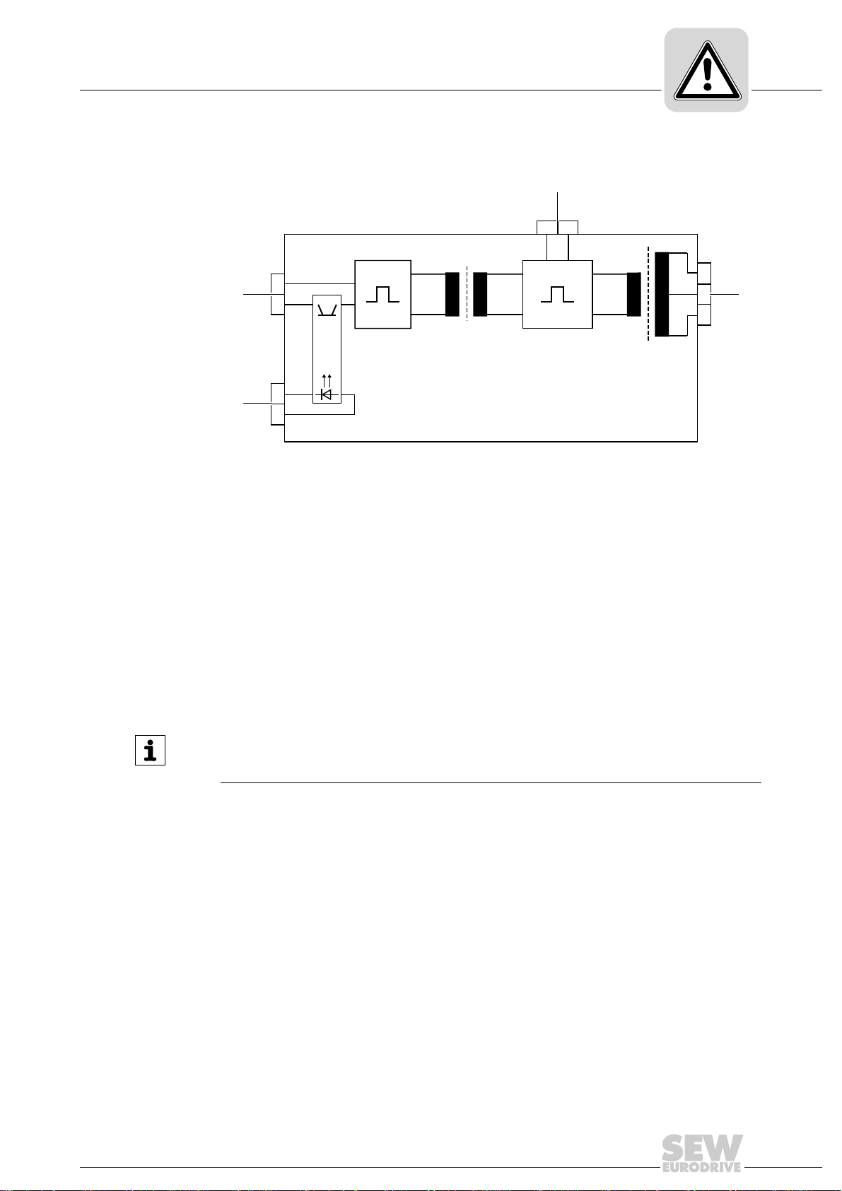
3.2.1 Block diagram BST
34
56
13 14 15
12
[1]
[4]
[3]
[2]
Phone: 800.894.0412 - Fax: 888.723.4773 - Web: www.clrwtr.com - Email: info@clrwtr.com
[1] DC link voltage input V
[2] Brake output (terminals 13/14/15)
[3] Functional control voltage input V
[4] Safety-related control voltage input V
Integrated Safety Technology
Safety function
(terminal 1/2)
DC link
(terminal 3/4)
24 V in
24 V safe
(terminal 5/6)
3
9007201124185483
3.3 Safety function
The following drive-related safety function can be used:
• SBC (Safe Brake Control according to IEC 61800-5-2)
The SBC function safely de-energizes the connected brake by disconnecting the
safety-related control voltage V
disconnected using a suitable external safety switching device/safety controller.
INFORMATION
Safety-related brake control must be carried out using the safety-related control
voltage V
24 V safe
(terminal 5/6) only.
24 V safe
. The safety-related control voltage must be
Operating Instructions – Safety-Related BST Brake Module
11
Page 12

3
Phone: 800.894.0412 - Fax: 888.723.4773 - Web: www.clrwtr.com - Email: info@clrwtr.com
3.4 Restrictions
Integrated Safety Technology
Restrictions
WARNING
Voltage is still present at the DC link connection of the frequency inverter even when
disconnecting the safety-related control voltage V
V
Severe or fatal injuries from electric shock.
• If work is carried out on the electrical section of the brake system, the supply
.
24 V in
voltage must be disconnected using an external maintenance switch.
24 V safe
/ functional control voltage
INFORMATION
• The safety concept is only suitable for performing mechanical work on the system/
machine components.
• A system/machine-specific risk assessment must be carried out by the system/
machine manufacturer and be observed when using the drive system with BST.
12
Operating Instructions – Safety-Related BST Brake Module
Page 13

4 Safety-Relevant Conditions
Phone: 800.894.0412 - Fax: 888.723.4773 - Web: www.clrwtr.com - Email: info@clrwtr.com
The safety function of BST can only be used for safe operation of the system/machine
if it is integrated correctly in an application-specific, higher-level safety function or safety
system. It is essential that the system/machine manufacturer conducts a system/
machine-specific risk assessment (e.g. according to EN ISO 12100) and validates the
required safety conditions and functions prior to startup. The system/machine manufacturer and the operator are responsible for compliance of the system/machine with
applicable safety regulations.
The following requirements are mandatory when installing and operating the BST brake
module in safety-related applications.
The conditions are divided into the following sections:
• Approved device combinations
• Installation requirements (page 14)
• Requirements for the external safety controller (page 16)
• Startup requirements (page 17)
• Operation requirements (page 18)
Safety-Relevant Conditions
Permitted unit combinations
4
4.1 Permitted unit combinations
The following BST unit types are permitted for safety-related applications:
Type designation Part number Approved SEW disk brakes
BST 0.6S-460V-00 0 829 971 4 All brake coils with a coil voltage of AC 460 V and a coil power
BST 0.7S-400V-00 1 300 077 2 All brake coils with a coil voltage of AC 400 V and a coil power
BST 1.2S-230V-00 1 300 133 7 All brake coils with a coil voltage of AC 230 V and a coil power
≤ 120 W.
Several brake coils can be connected for redundant systems.
In this case, the total power must not exceed 120 W.
≤ 120 W.
Several brake coils can be connected for redundant systems.
In this case, the total power must not exceed 120 W.
≤ 120 W.
Several brake coils can be connected for redundant systems.
In this case, the total power must not exceed 120 W.
Operating Instructions – Safety-Related BST Brake Module
13
Page 14

4
Phone: 800.894.0412 - Fax: 888.723.4773 - Web: www.clrwtr.com - Email: info@clrwtr.com
Safety-Relevant Conditions
Requirements on the installation
Only SEW disk brakes may be connected to the BST module.
Asynchronous motor type
Brake
type
BE05 xx
BE1 xxx
BE2 xx x
BE5 xxxx
BE11 xxx
BE20 xx
BE30 xxx
BE32 xxx
1) Brakes of the type BM or BM(G) 05 – 30 can be combined.
Brake
type
BY2 x
BY4 x
BY8 x
1) Brakes of the type B can be combined.
DR.71 DR.80 DR.90 DR.100 DR.112 DR.132 DR.160 DR.180 DR.200 DR.225
1)
Synchronous motor type
CMP.71 CMP.80 CMP.100
1)
4.2 Requirements on the installation
The line between the safety switching device/safety controller and the safety-related
BST brake module, terminal 5/6 (V
(for safe disconnection).
Observe the following requirements on the installation:
• Power lines and safety-related control lines have to be installed in separate cables.
• The total cable length between the safety switching device/safety controller and the
safety-related BST brake module is limited to a maximum length of 100 m for EMC
reasons.
• The total cable length between the safety-related BST brake module and the
connected brake must not exceed 200 m.
• Wiring must comply with EN 60204-1.
• The installation space (control cabinet) must have at least degree of protection IP54.
• The safety-related control lines must be routed according to EMC guidelines and as
follows:
– Outside an electrical installation space: Shielded cables must be routed perma-
nently (fixed) and protected against external damage, or other equivalent
measures.
– Individual conductors can be routed inside an electrical installation space.
Observe the respective regulations governing the application.
– It is essential that you apply the shielding at both ends on the housing.
• The safety-related control voltage V
24 V safe
24 V safe
) is referred to as safety-related control line
may not be used for feedback.
14
Operating Instructions – Safety-Related BST Brake Module
Page 15

Safety-Relevant Conditions
Phone: 800.894.0412 - Fax: 888.723.4773 - Web: www.clrwtr.com - Email: info@clrwtr.com
Requirements on the installation
• You have to make sure that there is no transient coupling to the safety-related control
voltage V
• Observe the values specified for safety components when designing the safety
circuits.
• Use only voltage sources with safe disconnection (SELV/PELV) according to
EN 60204-1 for any DC 24 V voltage supply (safety-related control voltage V
and functional control voltage V
In case of a single fault, the voltage between the outputs or between any output and
grounded parts must not exceed DC 60 V.
• Do not interconnect brake cables of several brake control systems.
• For disconnection of group drives, observe the switching capacity of the safety
switching device and the maximum permitted voltage drop on the safety-related
control voltage V
• Adhere to the technical data of the BST module and the brake.
• Adhere to the general installation regulations in the "Installation" chapter.
The following figure shows EMC compliant installation.
24 V safe
.
24 V safe
) of the safety-related BST brake module.
24 V in
.
24 V safe
4
Operating Instructions – Safety-Related BST Brake Module
9007199397615115
15
Page 16

4
Phone: 800.894.0412 - Fax: 888.723.4773 - Web: www.clrwtr.com - Email: info@clrwtr.com
Safety-Relevant Conditions
Requirements on external safety controller
4.3 Requirements on external safety controller
A safety relay can be used as an alternative to a safety controller. The following requirements apply analogously.
• The safety controller and all other safety-related subsystems must be approved for
at least that safety class which is required in the overall system for the applicationrelated safety function. The following table shows an example of the required safety
class of the safety controller.
Application Safety controller requirements
Category 3 according to EN 954-1 Category 3 according to EN 954-1
Performance level d according to EN ISO 13849-1 Performance level d according to EN ISO 13849-1
• The wiring of the safety controller must be suitable for the required safety class, (see
manufacturer documentation). The safety-related control voltage V
safely disconnected either at the positive, or the positive and negative pole. SEWEURODRIVE recommends bipolar disconnection.
• The values specified for the safety controller must be strictly adhered to when
designing the circuit.
• The switching capacity of the safety relays or the relay outputs of the safety controller
must correspond at least to the maximally permitted, limited output current of the
safety-relevant control voltage V
concerning the permitted contact loads and fusing tha t my be requir ed for the
safety contacts. If there are no manufacturer's instructions for fusing, the
contacts must be protected with 0.6 times the nominal value of the maximum
contact rating specified by the manufacturer.
24 V safe
Performance level d according to EN ISO 13849-1
SIL 2 according to EN 61508
SIL 2 according to EN 61508
24 V safe
can be
. Observe the manufacturer's instructions
• To ensure protection against unintended restart in accordance with EN 1037, the
safety controllers must be designed and connected in such a way that resetting the
control device alone does not lead to a restart. A restart may only be carried out after
a manual reset of the safety circuit.
• The input of the safety-relevant control voltage V
24 V safe
of the safety-relevant BST
brake module (terminal 5/6) is equipped with a serial polarity protection diode and a
buffer capacitor with C = 6 μF. This must be considered as load when dimensioning
the switching output.
• When switching off the BST with tested safe outputs, the switch-off test pulses must
not exceed 1 ms. The next pulse blanking cannot reoccur earlier than after 20 ms.
16
Operating Instructions – Safety-Related BST Brake Module
Page 17

4.3.1 Sample circuit for a "safety switching device"
Safety-related
control voltage V
of the safety switching device
Safety switching device
Fuses according to the
specifications of the
safety switching device
manufacturer
DC 24 V
GND
DC 24 V voltage supply
Approved
emergency stop device
Reset button
24 V safe
Phone: 800.894.0412 - Fax: 888.723.4773 - Web: www.clrwtr.com - Email: info@clrwtr.com
The following figure shows the basic connection of an external safety switching device
(according to the before mentioned requirements).
Observe the information in the respective manufacturer's data sheets for connection.
Safety-Relevant Conditions
Requirements on startup
4
4.4 Requirements on startup
9007199399082635
• Startup must be documented and the functionality of the safety functions must be
demonstrated. Observe the limitations for the safety functions of the BST brake
module in chapter "Restrictions" for the verification of the safety functions. Nonsafety-relevant parts and components that affect the result of the verification test
(e.g. brake rampe of a frequency inverter) must be deactivated, if necessary.
• For using the BST brake module in safety-relevant applications, it is essential that
you perform and record startup checks for the disconnecting device and correct
wiring.
• During the startup procedure/function test, the correct assignment of the respective
voltage supply connection must be checked by means of a measurement.
– Safety-relevant control voltage V
– Functional control voltage V
24 V in
24 V safe
: Terminal 5/6
: Terminal 3/4
• The function check must be carried out separately for all potentials.
• Observe the notes in the "Startup" chapter.
Operating Instructions – Safety-Related BST Brake Module
17
Page 18

4
Phone: 800.894.0412 - Fax: 888.723.4773 - Web: www.clrwtr.com - Email: info@clrwtr.com
Safety-Relevant Conditions
Requirements on the operation
4.5 Requirements on the operation
• Operation is only allowed within the limits specified in the data sheets. This applies
to both the external safety relay as well as the BST.
• You must check the safety functions on a regular basis to ensure proper functioning.
The the test intervals should be specified in accordance with the risk assessment.
• Also observe the information in the "Inspection/Maintenance" chapter.
18
Operating Instructions – Safety-Related BST Brake Module
Page 19

5 Unit Design
US
LISTED
Phone: 800.894.0412 - Fax: 888.723.4773 - Web: www.clrwtr.com - Email: info@clrwtr.com
5.1 Nameplate, type designation
5.1.1 Example: Type designation
The following characteristic unit data can be read from the type designation:
BST 0.6 S - 460V - 00
Unit Design
Nameplate, type designation
Version/type
Brake
voltage
Design S = Control cabinet module
Nominal output current 0.6 = DC 0.6 A
Series
460 V = AC 460 V (DC 190 V)
400 V = AC 400 V (DC 167 V)
230 V = AC 230 V (DC 96 V)
0.7 = DC 0.7 A
1.2 = DC 1.2 A
5
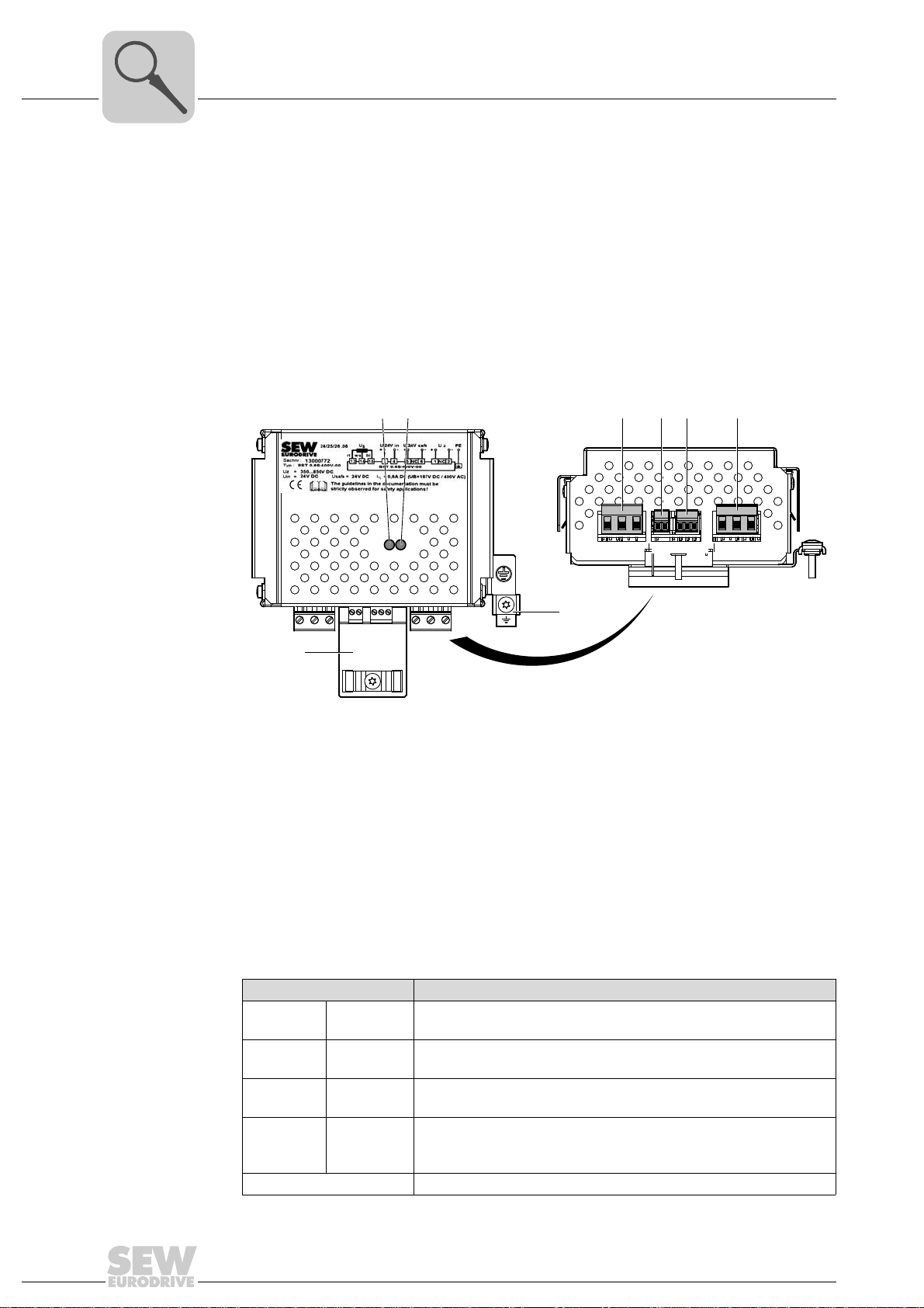
5.1.2 Example: Nameplate
The following figure shows a nameplate of BST 0.6S-460V-00:
[4]
[3]
[2]
[1]
[1] Output current (I
[2] Functional control voltage (V
[3] DC link voltage (V
[4] Type designation
[5] Serial number
[6] Part number
[7] Nominal output current (I
[8] Safety characteristics
[9] Degree of protection (IP) and ambient temperature (T)
[5]
08299714.1111
0004642
Typ : BST 0.6S−460V −00
Uz=
350 . . . 750V DC
Uin=
24V DC
Ibreak warm=
Usafe=
0.5A DC
24V DC
[9]
brake warm
DC link
[6]
U
DBI24 DGND SVI24 S0V24
B
++ +---
rd wh bu
13 14 15 3 4 5 NC 6 1 NC 2
IN = 0.6A DC (UB=190V DC / 460V AC)
WHEN USED WITH LISTED DRIVE SERIES:
MOVIDRIVE MOVITRAC
EN ISO 13849-1 Kat. 3 / PL d
IP 20 T= -15 ... +60°C
MANUFACTURED BY SEW-EURODRIVE ML 0001
[8]
) in warm condition
) and safety-related control voltage (V
in
)
) and brake voltage (VB)
N
Uz PE
18014398652394507
)
safe
[7]
CE mark to state compliance with European guidelines, such as the Low Voltage Directive.
UL logo to confirm that the component is UL (Underwriters Laboratory) tested, also valid for
US
®
CSA in conjunction with register number 2D06.
LISTED
Operating Instructions – Safety-Related BST Brake Module
19
Page 20
5
13/14 /15 1/NC /23/4 5/NC/6
[3] [4] [5] [6]
[8]
[7]
[1] [2]
Phone: 800.894.0412 - Fax: 888.723.4773 - Web: www.clrwtr.com - Email: info@clrwtr.com
Unit Design
Scope of delivery of BST
5.2 Scope of delivery of BST
The scope of delivery includes:
• 1 safety-related BST brake module with installed holding fixture for support rail
mounting
• 4 attached plug connectors for terminal connections
5.3 Safety-related BST brake module
The following figure shows the unit design of BST x.xS-xxxV-00:
[1] LED V1 for indicating the operating state
[2] LED V2 for indicating the operating state
[3] Terminals 13/14/15: Brake connection
[4] Terminals 3/4 : For connecting the functional control voltage V
[5] Terminals 5/6 : For connecting the safety-related control voltage V
[6] Terminals 1/2 : DC link voltage connection V
[7] PE connection
[8] Retaining plate / shield plate
5.4 Terminal assignment
Terminal Function
1
2
5
6
3
4
13
14
15
댷 Protective grounding
+U
Z
- U
Z
SVI24
S0V24
DBI24
DGND
RD
WH
BU
24 V in
24 V safe
DC link
DC link voltage input V
Safety-related control voltage V
Reference potential for safety-related control voltage V
Functional control voltage input V
Reference potential for functional control voltage V
Brake output
z
input
24 V safe
24 V in
24 V in
9007199397613451
24 V safe
20
Operating Instructions – Safety-Related BST Brake Module
Page 21

6 Installation
Phone: 800.894.0412 - Fax: 888.723.4773 - Web: www.clrwtr.com - Email: info@clrwtr.com
6.1 Mechanical Installation
6.1.1 Support rail mounting
The BST module is mounted onto a support rail in the control cabinet.
Installation
Mechanical Installation
6
Mounting
137090187
[1]
[2]
[3]
[4]
[5]
[6]
1887424139
[1] Safety-related BST brake module
[2] Support rail
[3] Upper holding fixture of the BST
[4] Notch, lower holding fixture of the BST
[5] Upper support rail edge
[6] Lower support rail edge
1. The upper holding fixture of the BST [3] is spring-loaded. First, insert the BST into
the upper support rail edge [5] with the upper holding fixture only.
2. Next, press the BST downward towards the support rail until the notch [4] clicks into
place on the lower support rail edge [6].
The spring at the upper holding fixture causes the lower support rail edge to be
pressed into the notch so that the BST [1] is secured onto the support rail [2].
Operating Instructions – Safety-Related BST Brake Module
21
Page 22

6
15 15
70
30 (1.18)
(2.76)
(0.59) (0.59)
Phone: 800.894.0412 - Fax: 888.723.4773 - Web: www.clrwtr.com - Email: info@clrwtr.com
Removal 1. Press onto the BST from the top. This causes the lower support rail edge [6] to come
Installation
Mechanical Installation
off the notch [4]. At the same time, remove the BST from the lower holding fixture.
2. You can remove the BST from the support rail once the lower lock unfastens.
Minimum
clearance and
mounting position
• Leave 30 mm clearance at the top, 70 mm at the bottom and 15 mm at the sides for
optimum cooling. Make sure air circulation in the clearance is not impaired by cables
or other installation equipment.
• Ensure unobstructed cooling air supply and make sure that the units are not
subjected to heated air from nearby components.
• Install the units vertically only. Do not install the units horizontally, tilted or upside
down.
All dimensions in mm (in).
22
18014398646570507
Operating Instructions – Safety-Related BST Brake Module
Page 23

6.2 Electrical Installation
Phone: 800.894.0412 - Fax: 888.723.4773 - Web: www.clrwtr.com - Email: info@clrwtr.com
INFORMATION
• The safety-related BST brake module cannot be operated with sine-shaped power
regeneration.
• All poles must be disconnected from the supply system when work is carried out
on the electrical section of the system. Dangerous voltages may still be present for
up to 10 minutes after disconnection from the power supply system.
6.2.1 Information on electric a l ins tall at io n
Supply cable
(terminal 1/2)
The supply cable must meet the following conditions:
• The supply cables to the BST carry a high DC voltage (max. DC 970 V). The rated
voltage of the cable must amount to at least V
DIN VDE 0298).
• The inverter supply system must have a grounded star point (TT/TN). The operation
is not permitted for IT systems or systems grounded via an outer conductor.
• Cable cross section: 0.75 mm
Installation
Electrical Installation
/V = 300 V / 500 V (in accordance with
0
2
–2.5 mm2 (AWG19–AWG13)
6
Functional control
cable (terminal 3/4)
Safety-related
control cable
(terminal 5/6)
• Max. cable length: 100 m (328 ft)
• When several BST are connected to one DC link, the input power of the inverter must
be taken into account.
• All poles of the supply cable are protected with two corresponding DC fuses F1/F2
(recommended 1000 V/4 A).
INFORMATION
The fuses may not be required in compliance with IEC 60364-4-43 ((VDE 100 part
430) and EN 60204-1 if the supply cable to the BST is protected by the input fuse
located in front of the inverter, or if the following conditions are met:
• The cable length to the BST must not exceed 3 m.
• Do not lay cables in the vicinity of inflammable substances.
• Reduce the risk of short cirucits to a minimum.
• Use the greatest possible cable cross section.
The functional control cable must meet the following conditions:
2
• Cable cross section of 0.5 mm
• Max. cable length: 100 m (328 ft)
The safety-related control cable must meet the following conditions:
• Cable cross section of 0.5 mm
• Max. cable length: 100 m (328 ft)
– 1.5 mm2 (AWG20–AWG16)
2
– 1.5 mm2 (AWG20–AWG16)
Brake cable
(terminal 13/14/15)
Operating Instructions – Safety-Related BST Brake Module
• Cable cross section of 0.75 mm
• Max. cable length: 200 m (656 ft)
2
– 2.5 mm2 (AWG 19 – AWG 13)
23
Page 24

6
5
6
Installation space
BST
DC 24 V
Safety
switching device
SVI24
S0V24
N.C.
Safety-related
control voltage
V
24V safe
5
6
Installation space
Installation space
BST
Outside
installation space
Safety-related
voltage supply
24 V
N.C.
+U
24V safe
-U
24V safe
Safety
switching device
Phone: 800.894.0412 - Fax: 888.723.4773 - Web: www.clrwtr.com - Email: info@clrwtr.com
Installation
Electrical Installation
6.2.2 Double-pole safe disconnection
The following figure shows the wiring inside the installation space:
The following figure shows the wiring outside the installation space:
9007199388524427
24
9007199388555019
Operating Instructions – Safety-Related BST Brake Module
Page 25

6.2.3 Single-pole safe disconnection
Phone: 800.894.0412 - Fax: 888.723.4773 - Web: www.clrwtr.com - Email: info@clrwtr.com
The following figure shows the wiring inside the installation space:
Electrical Installation
Installation space
Installation
6
Installation space
Safety switching
device
DC 24 V
Safety switching
device
SVI24
5
Safety-related
DC 24 V
N.C.
6
S0V24
control voltage
V
24V safe
The following figure shows the wiring outside the installation space:
Outside install. space
Installation space
BST
5
SVI24
Safety-related
N.C.
6
S0V24
control voltage
BST
9007199388553355
V
24V safe
9007199388551691
INFORMATION
Safe single-pole disconnection is only permitted when short circuits in the safetyrelevant control cable between safety relay and BST can be ruled out (fault elimination
according to EN ISO 13849-2).
SEW-EURODRIVE recommends bipolar disconnection.
Operating Instructions – Safety-Related BST Brake Module
25
Page 26

7
t
off
1s
t
off
1s
t
off
1s
t
off
1s
t
on
t
on
t
on
t
on
t/s
Brake
control
signal
00
I
Phone: 800.894.0412 - Fax: 888.723.4773 - Web: www.clrwtr.com - Email: info@clrwtr.com
7Startup
7.1 Operating states
Startup
Operating states
• The brake is activated with the functional control voltage V
voltage V
V
V
is present Ⳏ Brake released.
24 V in
is not present Ⳏ Brake applied.
24 V in
• If the safety-related control voltage V
and the safety-related control voltage V
DC link
24 V safe
24 V safe
is disconnected, the brake is safely de-
when the DC link
24 V in
are present.
energized (SBC).
• If the DC link voltage V
is disconnected, the brake is de-energized.
DC link
The brake is released with high-sped excitation. Rapid brake application (DC and AC
switch-off) occurs when it is controlled using the V
V
24 V safe
safety-related control voltage.
functional control voltage or the
24 V in
The response time for releasing and applying the brake results from the response time
of the BST t
≤ 6 ms and the response or application time of the brake connected. For
R
information on response or application times, refer to the applicable operating instructions for motors.
INFORMATION
Fast disconnection (cut-off in the DC circuit) of the brake by the BST module is not part
of the safety function (SBC). The brake application time for cut-off in the AC circuit
must therefore be used.
NOTICE
The brake module might be damaged if required off periods are not adhered to.
Damage to the drive system.
• Adhere to the required off periods for the brake module.
7.1.1 Brake module control under normal operating conditions, e.g. automatic ope ration of the plant
With a brake coil power of P ≥ 70 W, you must ensure a timeout of at least 1 second for
brake control.
2950935051
26
Operating Instructions – Safety-Related BST Brake Module
Page 27

Startup
00
I
Phone: 800.894.0412 - Fax: 888.723.4773 - Web: www.clrwtr.com - Email: info@clrwtr.com
Operating states
7.1.2 Brake module control under special operating conditions, e.g. teach or jog mode
For teach or jog mode, for example, timeouts shorter than 1 second are possible. After
20 control pulses, a timeout of minimum 3 min is mandatory in this case.
7
Brake
control
signal
7.1.3 Operating state display
LEDs V1 and V2 indicate the operating state of the control inputs.
• LED V1: State of the safety-relevant control voltage V
• LED V2: State of the brake when the DC link voltage V
LED V1 LED V2 V
Off Off Off Off Brake de-energized
Off Off Off On Brake de-energized
Lights up orange Off On Off Brake de-energized
Lights up orange Lights up green On On Brake energized when V
INFORMATION
• The states of LED V1 and LED V2 must not be regarded as safety-relevant.
• The fact that the LED V1 and LED V2 are no longer illuminated does not indicate
that the safety-relevant BST brake module is de-energized and the brake is
applied.
• Even if LED V1 and LED V2 are not illuminated, DC link voltage V
present at the BST brake module.
max. 20 pulses
t
off
min. 180 s
24 V safe
V
24 V in
t
DC link
.
is present.
24 V safe
Operating state
present
DC link
2951034251
is
DC link
might be
Operating Instructions – Safety-Related BST Brake Module
27
Page 28

8
Phone: 800.894.0412 - Fax: 888.723.4773 - Web: www.clrwtr.com - Email: info@clrwtr.com
Inspection/Maintenance
Inspection and maintenance intervals
8 Inspection/Maintenance
WARNING
Risk of crushing if the hoist falls.
Severe or fatal injuries.
• Secure or lower hoist drives (danger of falling)
• Isolate the inverter, the motor and the brake from the power supply before starting
work, safeguarding them against accidental startup.
• Only use genuine spare parts in accordance with the valid parts list.
• Always install a new brake controller at the same time as replacing the brake coil.
• Observe the notes in the operating instructions for AC motors and brakemotors.
• Only qualified personnel may perform maintenance for the brake.
WARNING
There may still be dangerous voltages inside the unit and at the terminal strips for up
to 10 minutes after the BST has been disconnected from the power supply.
Severe or fatal injuries from electric shock.
• Disconnect the BST from the power supply and ensure that the unit cannot be
switched on unintentionally.
• Wait for 10 minutes before carrying out any maintenance or inspection work.
• Prior to maintenance or inspection work, make sure that the BST is de-energized.
CAUTION
The surface of the safety-related BST brake module can be very hot during operation.
Danger of burns.
• Let the BST cool down before you start working on it.
8.1 Inspection and maintenance intervals
The required inspection/maintenance intervals must be calculated by the system
manufacturer according to the specific project planning documents for individual applications, in accordance with the regionally valid standards.
8.2 Checking the brake function
The brake function must be checked according to the instructions of the system
manufacturer after inspection/maintenance work.
28
Operating Instructions – Safety-Related BST Brake Module
Page 29

8.3 Service
Phone: 800.894.0412 - Fax: 888.723.4773 - Web: www.clrwtr.com - Email: info@clrwtr.com
Have the following information available when you require assistance from the SEWEURODRIVE service:
• Nameplate data (complete)
• Type and extent of the problem
• Time the problem occurred and any accompanying circumstances
• Assumed cause
8.4 Unit replacement
Proceed as follows to replace a BST:
• Observe the notes regarding inspection/maintenance work for the BST.
• DANGER There may still be dangerous voltages inside the unit and at the terminal
strips for up to 10 minutes after the BST has been disconnected from the power
supply.
Severe or fatal injuries from electric shock.
– Disconnect the BST from the power supply and ensure that the unit cannot be
switched on unintentionally.
Inspection/Maintenance
Service
8
– Wait for 10 minutes before carrying out any maintenance or inspection work.
– Prior to maintenance or inspection work, make sure that the BST is de-energized.
• Compare the data on the nameplate of the BST to be replaced with the new one.
• Remove all connecting terminals.
• Disconnect the PE and the shield clamps.
• Push lightly on the opposite side of the connection terminals and remove the BST
from the support rail.
• Install the new BST on the support rail. Observe chapter "Mechanical Installation".
• Connect the PE and the shield.
• Connect all connection terminals.
Operating Instructions – Safety-Related BST Brake Module
29
Page 30

9
Phone: 800.894.0412 - Fax: 888.723.4773 - Web: www.clrwtr.com - Email: info@clrwtr.com
9 Applications
Applications
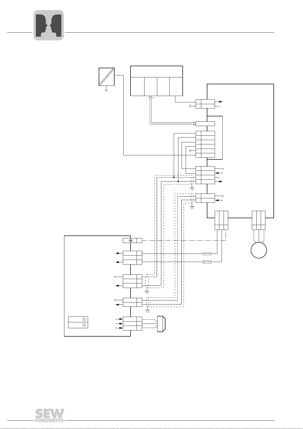
The following figures show the wiring diagrams for SBC with simultaneous STO
(Safe Torque Off).
INFORMATION
• For safe single- and double-pole disconnection, refer to chapter "Electrical Installation"
• DC fuses F1/F2 are not required if the before mentioned requirements for the
supply cable are met.
• Observe chapter "Electrical Installation".
30
Operating Instructions – Safety-Related BST Brake Module
Page 31

Applications
X13:
X2:
X4:
MOVIDRIVE B
Safety-rated
brake module - BST
®
654
Enable/stop
/Controller inhibit
Reference potential binary signals
87
W
V
U
PE
Uz+
Uz-
1
4
7
DIØØ
DIØ3
X17:
DC+24 V input
Reference potential binary signals
DC+24 V output
Reference potential DC+24 V input
1
2
3
4
DGND
VO24
SOV24
SVI24
DCOM
DC link connection
DC link connection
2
1
Uz-
N.C.
Uz+
X10:
Regerence potential binary signals
/Brake
2
3
DGND
DBØØ
6
5
S0V24
N.C.
SVI24
blue
white
red
4
3
DGND
DBI24
15
14
13
BU
WH
RD
M
B
Feedback
emergency stop
Reset
DC 24 V
Start
Stop
Emergency
stop
~
GND
=
CPU
Higher-level
controller
DI
DO
Safety
relay
~
F1/F2
LED V2
LED V1
Reference potential V
24 V safe
V
24 V safe
Reference potential V
24 V in
V
24 V in
Phone: 800.894.0412 - Fax: 888.723.4773 - Web: www.clrwtr.com - Email: info@clrwtr.com
Disconnection of single drives via inverter (example MOVIDRIVE® B)
9.1 Disconnection of single drives via inverter (example MOVIDRIVE® B)
9
18014398643152907
Operating Instructions – Safety-Related BST Brake Module
31
Page 32
9
X13:
X2:
X4:
MOVIDRIVE B
®
654
/Controller inhibit
Reference potential for binary signals
87
W
V
U
PE
Uz+
Uz-
1
7
DIØØ
X17:
DC+24 V input
Reference potential binary signals
DC+24 V output
Reference potential DC+24 V input
1
2
3
4
DGND
VO24
SOV24
SVI24
DCOM
X10:
Reference potential binary signals
/Brake
2
3
DGND
DBØØ
X30:
X31:
1
2
3
4
5
6 24V_PS
24V_LS
GND
GND
F_DO_P
F_DO_M
M
B
CPU
F_CPU
Higher-level
controller
DI
F_DI
DO
F_DO
PROFIBUS
PROFINET
PROFIsafe
DFS11B/21B
F1/F2
~
Safety-related
brake module - BST
DC link connection
DC link connection
2
1
Uz-
N.C.
Uz+
6
5
S0V24
N.C.
SVI24
blue
white
red
4
3
DGND
DBI24
15
14
13
BU
WH
RD
LED V2
LED V1
~
GND
=
DC 24 V
Reference potential V
24 V safe
V
24 V safe
Reference potential V
24 V in
V
24 V in
Phone: 800.894.0412 - Fax: 888.723.4773 - Web: www.clrwtr.com - Email: info@clrwtr.com
Applications
Disconnection of single drives via inverter and DFS11B/21B fieldbus inter-
9.2 Disconnection of single drives via inverter and DFS11B/21B fieldbus interface
32
Operating Instructions – Safety-Related BST Brake Module
18014399290419595
Page 33

9.3 Disconnection of group drives
X13:
X2:
X4:
MOVIDRIVE B
®
654
Enable/stop
/Controller inhibit
Reference potential binary signals
87
W
V
U
PE
Uz+
Uz-
1
4
7
DIØØ
DIØ3
X17:
DC+24 V input
Reference potential binary signals
DC+24 V output
Reference potential DC+24 V input
1
2
3
4
DGND
VO24
SOV24
SVI24
DCOM
X10:
Reference potential binary signals
/Brake
2
3
DGND
DBØØ
M
B
B
Feedback
emergency stop
Reset
DC 24 V
Start
Stop
Emergency
stop
~
GND
=
CPU
Higher-level
controller
DI
DO
Safety
relay
F1/F2
~
M
~
Safety-related
brake module - BST
DC link connection
DC link connection
2
1
Uz-
N.C.
Uz+
6
5
S0V24
N.C.
SVI24
blue
white
red
4
3
DGND
DBI24
15
14
13
BU
WH
RD
LED V2
LED V1
Reference potential V
24 V safe
V
24 V safe
Reference potential V
24 V in
V
24 V in
Phone: 800.894.0412 - Fax: 888.723.4773 - Web: www.clrwtr.com - Email: info@clrwtr.com
Applications
Disconnection of group drives
9
18014398643154571
Operating Instructions – Safety-Related BST Brake Module
33
Page 34

10
P
i
f
kVA
Hz
n
Phone: 800.894.0412 - Fax: 888.723.4773 - Web: www.clrwtr.com - Email: info@clrwtr.com
Technical Data
General technical data
10 Technical Data
10.1 General technical data
Brake module BST 1.2S-230V-00 BST 0.7S-400V-00 BST 0.6S-460V-00
Part number 1300 1337 1300 0772 0829 9714
Interference immunity According to EN 61800-3
Interference emission with EMC-
compliant installation
Degree of protection IP20
Installation On support rail in control cabinet
(control cabinet must have have at least degree of protection IP54)
Ambient temperature T
Climate class EN 60721-3-3, class 3K3
DC link voltage
Terminal 1/2
Power consumption
Terminal 1/2
Functional control voltage
Terminal 3/4
Brake voltage
Terminal 13/15
AC brake coil voltage AC 230 V AC 400 V AC 460 V
Nominal output current
Terminal 13/15
Output current
Terminal 13/15
Acceleration current
Terminal 13/14
Max. output power P
Brake output
Terminal 13/14/15
Disconnection Cut-off in the DC and AC circuits (rapid application of the brake)
Supply cable
Terminal 1/2
Functional control cable
Terminal 3/4
Brake cable
Terminal 13/14/15
Power loss P
Storage temperature −20 °C to +70 °C (EN 60721-3-3, class 3K3)
Dimensions W × H × D 134 mm × 70 mm × 135 mm (5.28 in × 2.76 in × 5.31 in)
Weight About 0.79 kg (1.7 lb)
A
V
Z
P
E
V
24 V in
V
B
I
N
I
brake warm
I
B
out
V
Z
V
24 V in
V
DC 350 V – 750 V (briefly up to DC 970 V)
Signal level according to DIN EN 61131-2 type 1
DC +15 V to +30 V (> 2mA) => 1 / contact closed
DC −3 V to +5 V (< 2 mA) => 0 / contact open
You must only use grounded voltage sources with safe disconnection (PELV) according to
DC 96 V DC 167 V DC 190 V
DC 1.2 A DC 0.7 A DC 0.6 A
DC 1.0 A DC 0.6 A DC 0.5 A
With P
Several brake coils can be connected for redundant systems. The sum of the individual
EN 60204-1 for the control input at terminals 3 and 4.
= 120 W, the nominal output current reduces in warm condition.
A
4 – 8.5 times the holding current depending on the brake type
The figures relate to SEW standard brake coils (two-coil system)
power levels must not exceed the max. output power.
Rated cable voltage: min. V0 / V = 300 V / 500 V (to DIN VDE 0298)
Cable cross section: 0.75 mm
Cable cross section: 0.5 mm2– 1.5 mm2 (AWG 20 – AWG 16)
Cable cross section of 0.75 mm
Max. cable length: 200 m (656 ft) at min. 1.5 mm
According to EN 61800-3
−15 °C to +60 °C
(at P
≥ 95 W at least DC 450 V)
A
150 W, depending on brake type
Short-term: max. 800 W / 200 ms
P
≤ 120 W
out
Holding coil: Terminal 13
Accelerator coil: Terminal 13
2
Max. cable length: 100 m (328 ft)
Max. cable length: 100 m (328 ft)
2
Max. 30 W
red
– 2.5 mm2 (AWG 19 – AWG 13)
– 2.5 mm2 (AWG 19 – AWG 13)
/ 15
red
/ 14
blue
white
2
(AWG 16)
34
Operating Instructions – Safety-Related BST Brake Module
Page 35

10.2 Safety-related control voltage
P
i
f
kVA
Hz
n
Phone: 800.894.0412 - Fax: 888.723.4773 - Web: www.clrwtr.com - Email: info@clrwtr.com
Technical Data
Safety-related control voltage
10
The following table shows the technical data for safety-related control voltage V
at terminals 5/6:
Safety-related control voltage V
Input voltage range
according to DIN EN 61131-2 DC 24 V
Input current 50 mA
Input capacitance 4.7 μF6μF
Switch-on/switch-off threshold DC 10 V
Input voltage for OFF state
(brake de-energized)
Duration from switching off the safety-related control
voltage at BST until switching off the brake voltage V
plus the brake application time of the connected
1)
brake.
Safety-related control cable
• Cable length
• Cable cross section
1) The brake application time for cut-off in the AC circuit must be used.
24 V safe
10.3 Safety characteristics o f BST brake modules
Min. Typical Max.
DC 20.4 V DC 24 V DC 28.8 V
B
2
0.5 mm
(AWG 20)
24 V safe
DC 6 V
6 ms
100 m
(328 ft)
1.5 mm2
(AWG 16)
Characteristic values to EN ISO 13849-1
Classification/underlying standards PL d
System structure Category 3
Probability of dangerous failure per
hour (PFH value)
Mission time / service life 20 years
Safe condition Brake de-energized
Safety function SBC (safe brake control) according to IEC 61800-5-2
0 (fault exclusion)
Operating Instructions – Safety-Related BST Brake Module
35
Page 36

10
89
101
135
70
99
121.5
74
135
(5.31)
(4.78)
(2.76)
(5.31)
(3.98)
(3.50)
(3.90)
(2.91)
P
i
f
kVA
Hz
n
Phone: 800.894.0412 - Fax: 888.723.4773 - Web: www.clrwtr.com - Email: info@clrwtr.com
Technical Data
Dimension drawing of BST in control cabinet design
10.4 Dimension drawing of BST in control cabinet design
The following figure shows the dimension drawings of BST in control cabinet design:
All dimensions in mm (in).
36
Operating Instructions – Safety-Related BST Brake Module
9007199388556683
Page 37

Index
Phone: 800.894.0412 - Fax: 888.723.4773 - Web: www.clrwtr.com - Email: info@clrwtr.com
Index
A
Applicable documentation........................................6
Applications
Disconnection of group drives............................33
Disconnection of single drives via inverter and
DFS11B/21B fieldbus interface..........................32
®
Disconnection of single drives via MOVIDRIVE
inverter ...............................................................31
B
Block diagram
BST ....................................................................11
Brake function
Checking ............................................................28
BST
Block diagram ....................................................11
Dimension drawings...........................................36
Nameplate..........................................................19
Safety characteristics.........................................35
Technical data....................................................34
Type designation................................................19
Unit replacement................................................29
Unit structure......................................................20
B
I
Information on electrical installation
Brake cable (terminal 13/14/15).........................23
Functional control cable (terminal 3/4)............... 23
Safety-related control cable (terminal 5/6).........23
Supply cable (terminal 1/2) ................................23
Inspection ..............................................................28
Inspection intervals ................................................28
Installation
electrical.............................................................23
Mechanical......................................................... 21
Requirements .................................................... 14
Integrated safety technology.................................. 10
L
Liability.....................................................................6
Liability for defects ................................................... 6
M
Maintenance ..........................................................28
Maintenance intervals............................................28
Mechanical installation........................................... 21
C
Copyright..................................................................6
D
Designated use ........................................................8
Dimension drawings
BST ....................................................................36
Disposal ...................................................................9
Documentation, applicable.......................................6
Double-pole safe disconnection.............................24
E
Electrical installation...............................................23
Double-pole safe disconnection.........................24
Information .........................................................23
Single-pole safe disconnection ..........................25
Embedded safety notes ...........................................5
Exclusion of liability..................................................6
External safety controller
Requirements.....................................................16
N
Nameplate BST .....................................................19
Notes
Designation in the documentation .......................5
O
Operating states ....................................................26
Operation
Requirements .................................................... 18
P
Permitted unit combinations .................................. 13
Product names.........................................................6
R
Requirements
External safety controller ...................................16
Installation.......................................................... 14
Operation...........................................................18
Startup ............................................................... 17
Restrictions ............................................................12
48
Operating Instructions – Safety-Related BST Brake Module
Page 38

Index
Phone: 800.894.0412 - Fax: 888.723.4773 - Web: www.clrwtr.com - Email: info@clrwtr.com
S
Safe condition ........................................................10
Safe disconnection
double-pole ........................................................24
single-pole..........................................................25
Safety concept .......................................................10
Safety control, external
Requirements.....................................................16
Safety notes .............................................................7
Designation in the documentation........................5
Structure of the embedded safety notes ..............5
Structure of the section-related safety notes .......5
Safety switching device
Sample circuit ....................................................17
Safety technology
Integrated...........................................................10
Safety-relevant conditions......................................13
SBC safety function (Safe Brake Control) according
to IEC 61800-5-2................................................11
SBC, safety function according to IEC 61800-5-2..11
Scope of delivery
BST ....................................................................20
Section-related safety notes ....................................5
Service ...................................................................28
Signal words in the safety notes ..............................5
Single-pole safe disconnection ..............................25
Startup ................................................................... 26
Startup requirements .........................................17
Support rail mounting.............................................21
Minimum clearance and mounting position .......22
Mounting BST onto a support rail ......................21
Removing BST from the support rail..................22
T
Target group ............................................................8
Technical data
BST.................................................................... 34
General ..............................................................34
Safety characteristics.........................................35
Safety-related control voltage ............................35
Terminal assignment
BST.................................................................... 20
Trademarks..............................................................6
Transport ................................................................. 8
Type designation BST ........................................... 19
U
Unit combinations
Permitted ...........................................................13
Unit design
Safety-relevant BST brake module.................... 19
Unit structure
BST.................................................................... 20
Operating Instructions – Safety-Related BST Brake Module
49
 Loading...