

Seca 545 Service Manual

Service Manual
5459021004
29.06.2005
Variants:
5459021124
5459021754
5459021774
5459021954
5459121004
5459121964
5459517744
5459521694
for seca
Description:
Pedal crank ergometer with electromagnetic eddy current brake, pulse detection
circuit and serial Interface RS232 for connection to ECG-machines. The
Ergometer is a medical product.
545
Content:
Operation 17-10-05-237 c
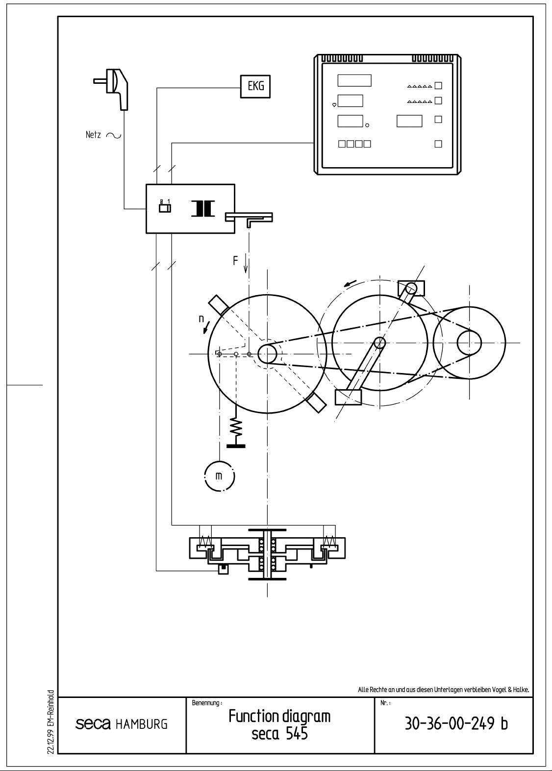
Function diagram 30-36-00-249 b
Mechanics 30-36-00-284
Service Manual Number
17-05-01-283-d
Valid as of:
Electronics 30-36-00-285
Pinning of connectors 30-36-00-283
Description of faults 30-36-00-286
Replacement 30-36-00-282 a
Calibration 30-36-00-287
Description serial Interface 30-36-00-275 b
spare parts 30-36-00-281 d
Manual number: 17-05-01-283-d

Service Manual
seca 545 Functional description of mechanical
equipment
seca 545 Ergometer Edition: November 1998
Pedal crank ergometer with electromagnetic eddy current brake
Design
Steel frame as supporting structure, rests stably on the floor on four points.
Supporting points consisting of 2 rollers to allow the unit to be moved easily
and 2 adjusting caps for levelling out any unevenness of the floor.
Height-adjustable saddle with locking lever.
Turning handlebar with locking lever. Height-adjustable handlebar support with locking lever.
The handlebar support also carries the operating and display panel.
The testee drives the ergometer via the pedal crank.
The torque is transmitted in two stages to the disk flywheel of the eddy current brake.
In the first stage the torque is transmitted via a conventional 1/2 x 1/8 “bicycle chain
to an intermediate bearing with freewheel.
Transmission of the second stage via a toothed belt (HDT-8M).
A solenoid that works as an eddy current brake is mounted in a pendulum bearing.
A power sensor measures the brake power, a photosensor measures the speed.
From speed and brake power a braking torque is calculated which is altered by changing the
current in the solenoid. Due to this type of control the ergometer is independent of the torque
applied by the testee.
The ergometer comprises electronic circuits for open and closed loop control.
25.02.99 Sievers Page 1 of 1 30-36-00-284

Service Manual
Ergometer 545 Description of the electronics
Description of the electronics
Description of the electronics Description of the electronics
Ergometer electronic circuit description
( 08-01-25-211 )
Overview:
The pedal crank ergometer described below is used to subject the pat ient to strain with a
predetermined muscle power input and to measure t he pulse f requency during this test. In order
to ensure these functions, electronics in SMD technology were developed which are described
below.
The ergometer electronics can be divided into three function blocks:
1. Digital section with µ-processor, serial inter face, EEProm, reset circuit, ECG relay and several
digital control lines for controlling the display and t he int ernal functions.
2. Sensor section with a pulse frequency sensor, a revolution sensor, a measuring amplifier with
DMS load cell for measuring the torque and a combined DA-AD converter in linear ramp
technology.
3. Power section with the power supply units for the eddy cur rent brake ( 30V ), the digital
section ( 5V ) and the analog / sensor section with the power cont r oller for the eddy current
brake.
Description of the digital section:
The µ-processor I9 is equipped with an integrated progr am m emory in OTP, flash or mask
technology. It controls the display and the butt on functions for controlling the ergometer via the
digit and segment bus. Using the internal signals “pulse” and “speed” a sof tware timer
determines the patient’s pulse frequency and the speed of t he br ake drum.
The remaining internal signals "CYCL", "SYNC" , "MOMENT", "BSET" and "OSET" the DA-AD
are used to control the converter, t o m easur e t he actual torque, to set the torque set point and
the offset value for the measur ing am plif ier.
The parameters recorded during calibration such as frict ion losses, scale factor and various
internal parameters are stored in t he EEPr om I7.
In order to branch from the st andard program to special modes a 4-position switch S1 is
provided. Presently it is used for setting t he offset for the measuring amplifier ( S1.2 ) and for
switching to calibration mode ( S1.4 ).
Serial communication, e.g. with a control PC or the test bench, is performed by inter face module
I6.
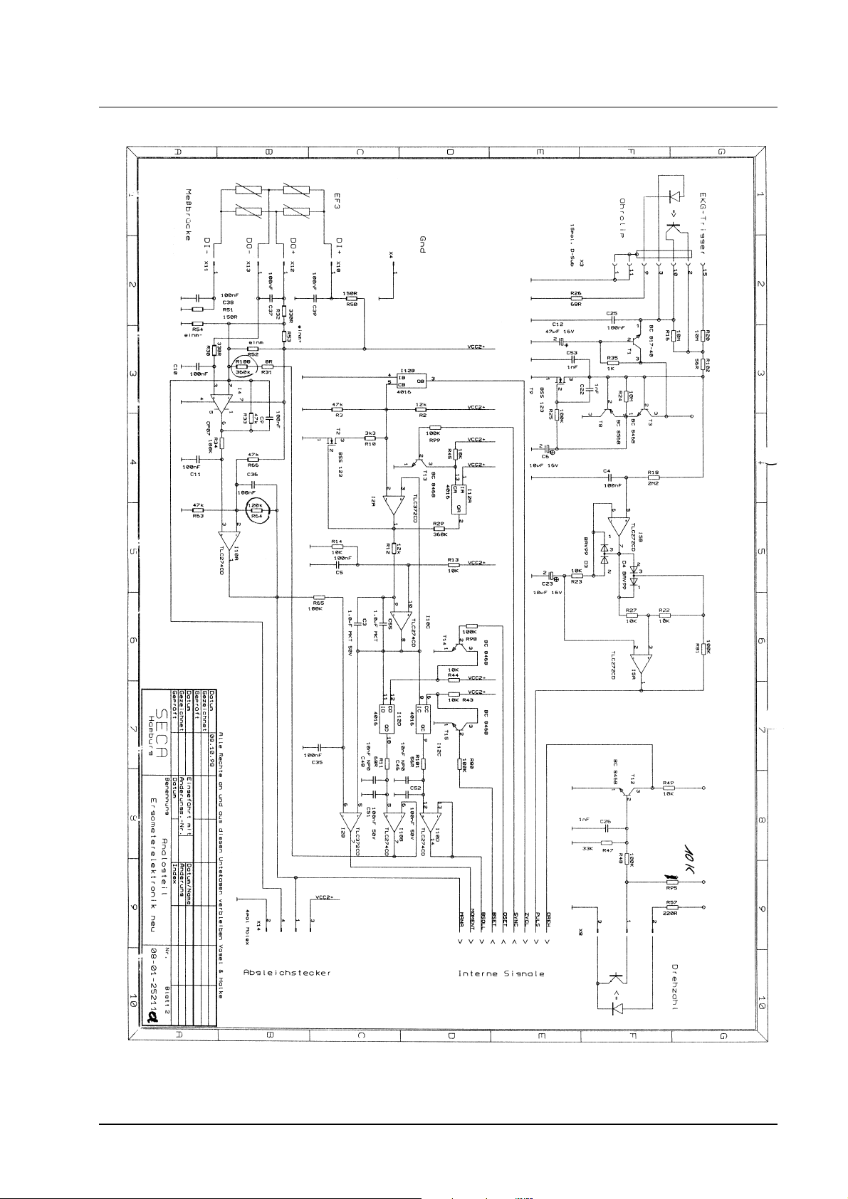
Description of the analog section:
a) The pulse frequency is measured by means of an infrared photosensor in the form of an ear
clip. The transmitter of the ear clip consists of an IR-LED which is supplied with a current of
30mA that is firmly set via R26.
The clip’s receiver is an IR-transistor which operates on a stabilized power supply T9. The
circuit’s operating point is controlled by the voltage at C6. The control voltage is generated
from the measuring signal via low-pass filter R24 / C6. The selected time constant of 100s is
long enough to ensure the measuring signal will not be corrupted. However, to allow fast
switch-on of the measurement, t r ansist or s T3 / T8 ar e provided to quickly correct the
operating point if the output voltage deviates by m o r e t han a base-emitter voltage from t he
current voltage level at C6.
The measuring signal produced passes via the low-pass filter R18 / C4 to amplifier I5B, which
10.03.1999 Panier Page 1 of 6 30-36-00-285

Service Manual
Ergometer 545 Description of the electronics
Description of the electronics
Description of the electronics Description of the electronics
operates with open loop gain, and from there to the Schmitt trigger I5A.
The resulting square-wave pulse signal "PULSE" is passed firstly to the pulse LED on the
display and secondly to the µ-P I9 for pulse frequency deter m inat ion. For triggering the pulse
frequency measurement from an ECG plot ter input X3.15 is available.
b) The speed is determined with a photosensor mounted to the er gometer brake. As the output
voltage of this photosensor is high enough, one transistor st age T12 is suf ficient to form the
square-wave pulse. The output voltage is passed as a "SPEED” signal to I9 which determines
the speed.
c) The current braking torque is determined by means of the DMS load cell EF3. Its output
voltage is amplified by I4 and I10A and is passed as an analog signal "MANA" to the AD
converter and as an analog value to the torque controller I3. The measuring amplifier I4 is
adjusted to the offset parameter s of the measuring cell used by means of resistors with wired
contacts R53 and R54. Coarse adjustment can be perfor med without taking into account the
spring pretension that will be set later, since t he pr ocessor will make a fine offset adjustment
via R100 during the operation.
d) The central part of the AD/DA converter is t he ramp generator consisting of I10C and I2A.
The actual measuring ramp starts at 9.5V and ends at 2.5V. The upper voltage limit is set by
the potential divider R2 and R3, the lower limit by R2 and R3//R10. Switch-over of the
reference voltages is effected by T2. The mom ent of switch-over is determined by I2A. The
ramp time is determined on the one hand by the two ref er ence voltages and on the other
hand by the integrating capacitor C55 ( C3 ) together with R29 and R12. For the given
component characteristics a time of 0.45 s is used. The t ime for the reset ramp (start at 2. 5V
and end at 9.5V) is set to 14.5ms via R12. By means of I 12B, which is connected as an
inverter/level converter, the processor det er mines the measuring ramp time for tem per at ure
compensation ("CYCL"). The analog switch I12A synchr onizes t he ramp with the µP
measuring timer ( "SYNC" ).
The analog switch I12C generates the analog setpoint for the torque controller ( "BSOLL" ) .
Control is performed by the µP using ( "BSET" ). The control voltage for the measuring
amplifier offset is produced in the sam e way via I 12D and the control signal "OSET".
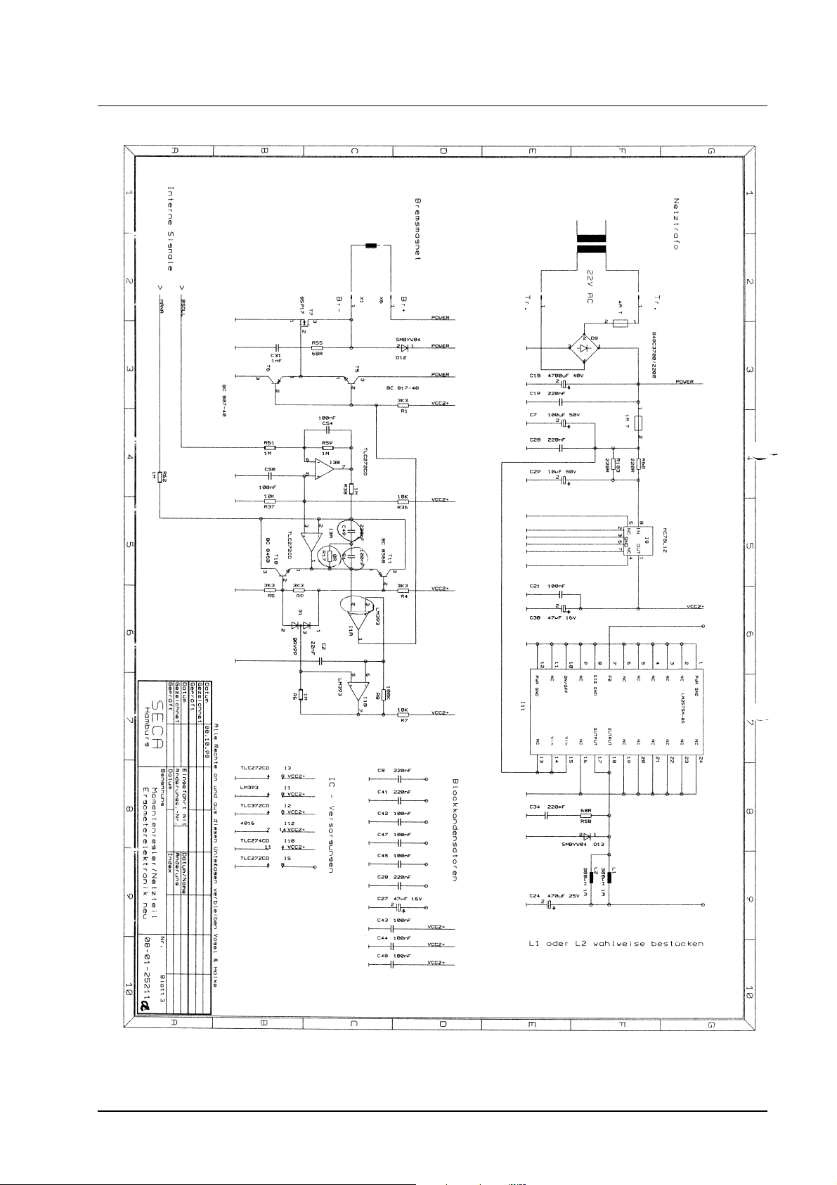
Description of the power section:
a) The Mosfet T7 provides the power supply for the brake. It is controlled by square-wave pulses
at a frequency of approx. 200Hz. The pulse duty factor for these pulses can be adjusted in the
range 0 to 1 via torque controller I3A. This causes t he br ake cur rent to vary between 0 and
approx. 3A, which is certainly sufficient for t he required braking torques. I1B is a sawtooth
voltage generator for generating the 200Hz control voltage. The sawtooth amplitude is
approx. 5V. The variable pulse duty factor for the control voltage for the brake solenoid is
generated by comparing this sawtooth voltage with the output voltage of torque controller I3A
( comparator I1A ). Torque cont roller I3A is an IT1 type with an integration time constant of
0.22s. Selecting this time constant allows the t orque controller to almost completely adjust the
specified torque within a DA interval. R17 and C1 are used t o optimize the controller
characteristics. T11 and T10 limit the maxim um cont roller stroke to the amplitude of t he
200Hz sawtooth to prevent the I-contr oller “overshoot ing” and producing detrimental delay
times in the control loop. I3B is an inverter for the torque setpoint ( "BSO LL" ). It has an
additional time constant C54, R59 and thus ensures smooth t ransitions if the torque setpoint
changes suddenly. Due to the analog controller the settling t im e f or the required braking
torque can be almost freely controlled by the processor ( > approx. 1s ).
10.03.1999 Panier Page 2 of 6 30-36-00-285

Service Manual
Ergometer 545 Description of the electronics
Description of the electronics
Description of the electronics Description of the electronics
b) The power supply unit produces the three required ergom et e r oper ating voltages: Power,
VCC, VCC2+.
“Power” supplies the current for the brake and for the two other power supply unit s . Fuse
protection is provided by fuse 4AT. VCC’s operating current can be as high as 800mA due to
the LED display. Consequently, a low loss switching controller I11 is used here. As a result of
a suitable layout and the selected components the voltage ripple is appr ox. 80m V, which,
among other things, keeps interfering radiation low. VCC is fuse protected by an SMD fuse
1AT.
As the current is only approx. 40 mA, the analog me asur ing cir cuit is supplied by an analog
voltage regulator I8. High accuracy or tem perature stability is not required since all measur ing
voltages are derived from this voltage and fluctuat ions are thus compensated.
The ergometer is electrically isolated from t he m ains by a conventional mains transformer. O n
the primary side the transform er is pr ot ected by a two-phase fuse. An interference filter
prevents interference being injected into the cir c uit .
10.03.1999 Panier Page 3 of 6 30-36-00-285
Service Manual
Ergometer 545 Description of the electronics
Description of the electronics
Description of the electronics Description of the electronics
10.03.1999 Panier Page 4 of 6 30-36-00-285
Service Manual
Ergometer 545 Description of the electronics
Description of the electronics
Description of the electronics Description of the electronics
10.03.1999 Panier Page 5 of 6 30-36-00-285
 Loading...