

SEA JOINT Installation Manuals And Safety Information
®
Sistemi Elettronici
di Apertura Porte e Cancelli
JOINT
67411932
INSTALLATION MANUALS
AND SAFETY INFORMATION
SEA S.p.A.
Zona industriale 64020 S.ATTO Teramo - (ITALY)
Tel. +39 0861 588341 r.a. Fax +39 0861 588344
www.seateam.com
seacom@seateam.com
REV.01 - 08/2016
1

®
JOINT
Sistemi Elettronici
di Apertura Porte e Cancelli
TABLE OF CONTENTS
PERIODICAL MAINTENANCE.................................................................................................................3
FEATURES AND SPECIFICATIONS........................................................................................................4
SAFETY OPERATING GATE....................................................................................................................5
CONFIGURATION AND SPECIFICATION................................................................................................6
CONCRETE PAD AND GATE ATTACHMENT.........................................................................................7
STANDARD INSTALLATION..................................................................................................................8
GATE ARM INSTALLATION....................................................................................................................10
GATE MOVEMENT DIRECTION............................................................................................................11
LEFT OPERATOR MOUNTING ..............................................................................................................12
RIGHT OPERATOR MOUNTING ...........................................................................................................13
MOUNTING PLATE................................................................................................................................14
TORQUE ADJUSTMENT........................................................................................................................14
LIMIT SWITCHES...................................................................................................................................15
CONTROL UNIT SUPPORT ..................................................................................................................15
MANUAL RELEASE SYSTEM................................................................................................................16
GENERAL NOTICE FOR THE INSTALLER AND THE USER ..............................................................17
2
®
JOINT
Sistemi Elettronici
di Apertura Porte e Cancelli
PERIODICAL MAINTENANCE
1) Check the oil level in the hydraulic/oil-bath operators (transparent cap placed in the
Products)
2) Change the oil in case of low level
3) Check the release function
4) Check the fixing screws
5) Check the integrity of the connection cables
6) Check the function and the limit switch condition in opening and closing
7) Check for all corroded parts and replace them
8) Check the robustness and the stability of the gate; particularly the leaning and/or rotation
points of the gate ( hinges)
9) Check the operating of all accessories. Especially the functioning of all safety devices and
reversing sensors
All the above described operations MUST be made exclusively by an
authorized installer.
3
®
Sistemi Elettronici
di Apertura Porte e Cancelli
MECHANICAL INSTALLATION
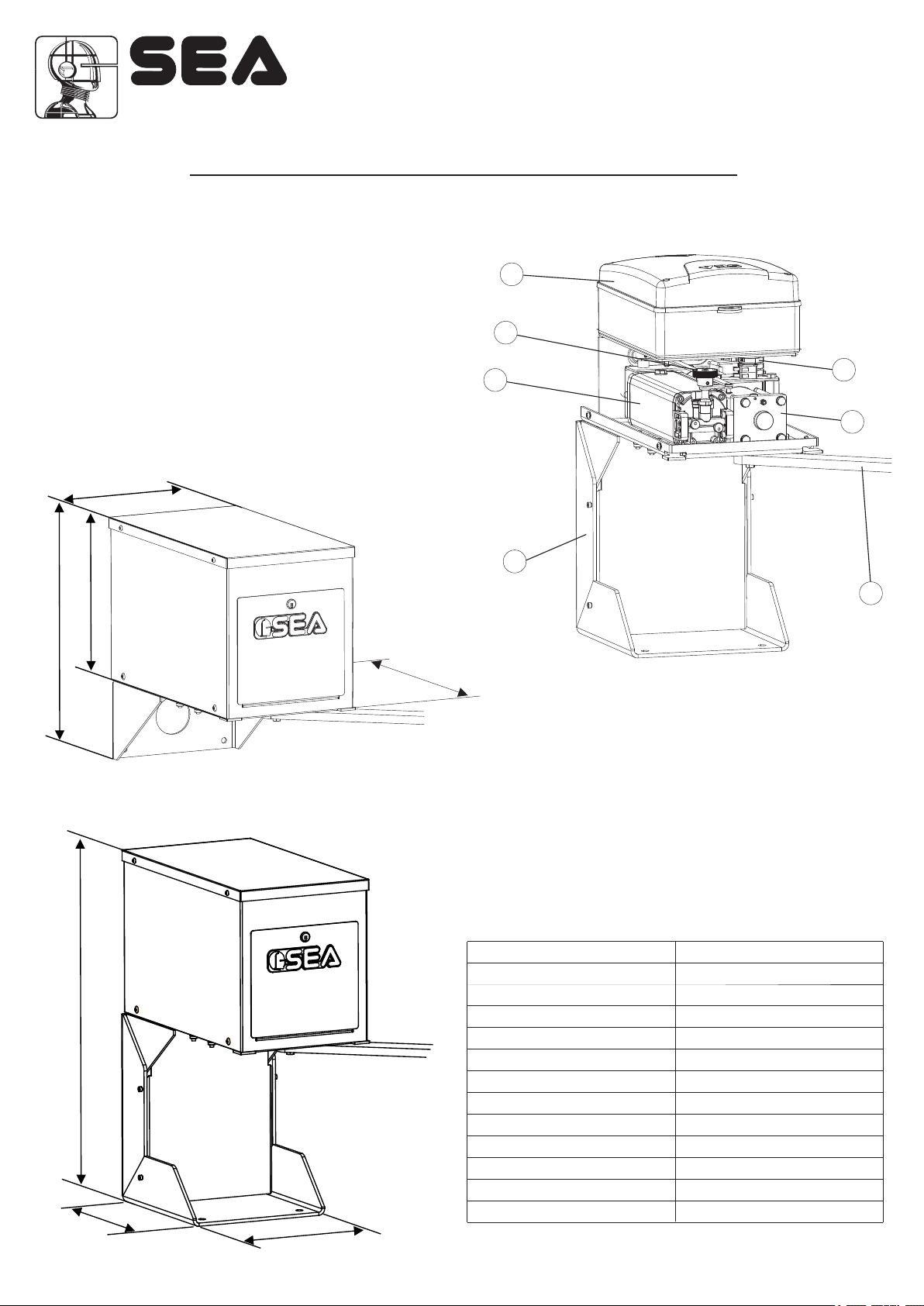
1. Features and specifications
Jointed swing operator pad mounted for residential/commercial use.
1
1. lectronic control unitE
2. Hydraulic unit
3. Ground support (OPTIONAL)
4. Manual release
5. Articulated arm
6. Jack
7. Limit switch
4
2
JOINT
7
6
457
305
255
Dimensions (mm)
Fig.2
3
5
Fig.1
483
TECHNICAL FEATURES
Gate Speed: 8 - 12 seconds per 90° cycle
Maximum Gate Length: 6 mm
Maximum Gate Weight: 455 kg
Maximum Cycles: 250 cycles per day with Sea's Plug-
In Transformer. (Gate size 6 m x 2,4 m)
AC Power Supply Wire: 14 gauge or greater landscape
lighting cable rated for direct burial and
300 watts at maximum length of 305 m
SPECIFICATIONS
660
305
Fig.3
Power supply
Motor power
Operation temperature
Max. beam length
Protection class
Opening time 90° (sec)
Cycles/hour
Max leaf weight
Max opening angle (degrees)
Anti-crushing protection
Limit switch
Slow-down
Mechanical/electronic
230V
280 W
-20°C to +55°C*
6 m
Ip44
8 - 12 sec
40
455 kg
100°
By pass valve
Electronic
280
4
Sistemi Elettronici
di Apertura Porte e Cancelli
MECHANICAL INSTALLATION
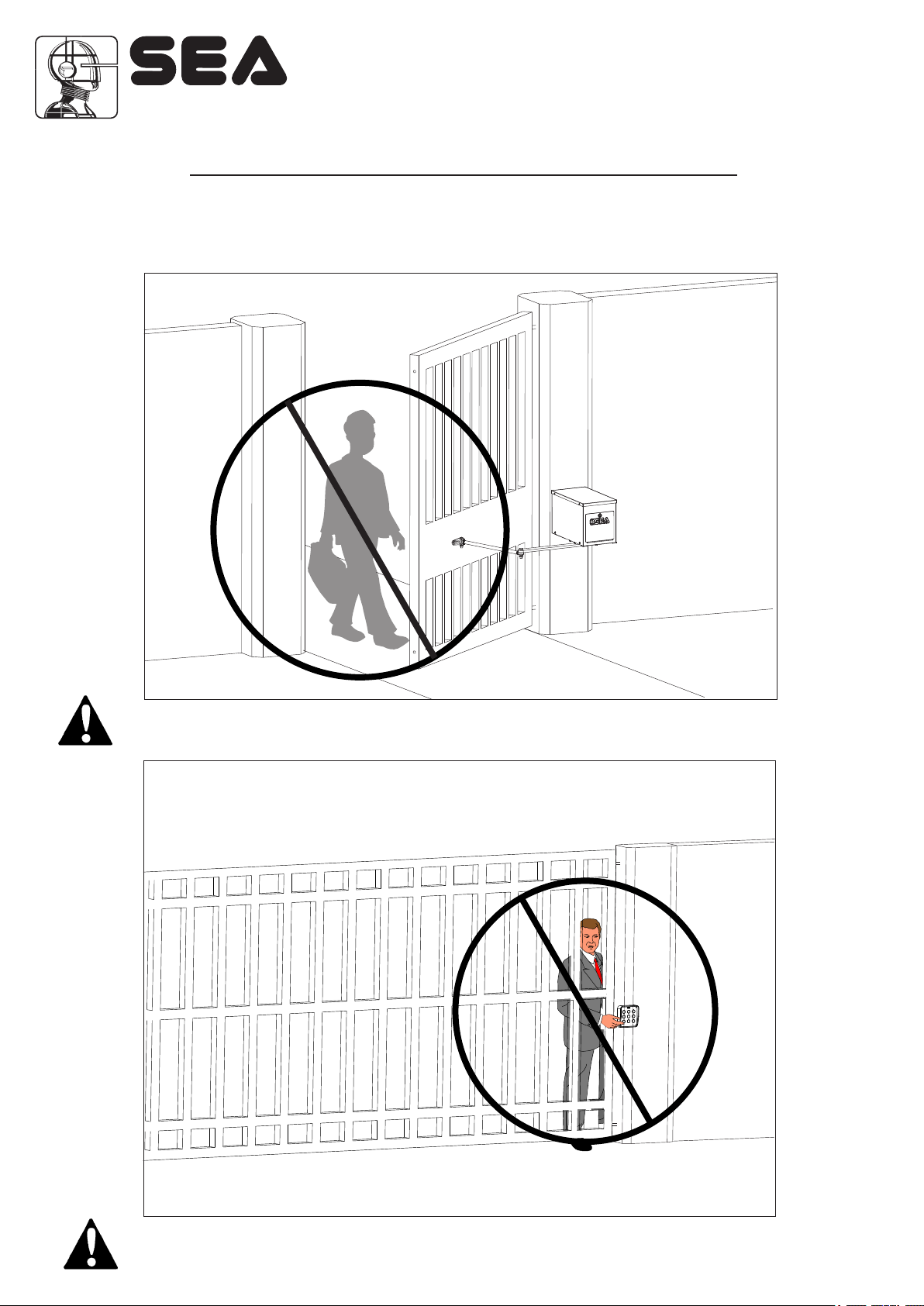
2. Safety operating gate
The Joint 230V is for Single Home Applications
DO NOT Use for Apartment or Condominium Applications.
®
JOINT
Fig.4
Owners Must Never Let Pedestrians Cross the Path, Step or Hang on a Moving Gate!
Owners Must Never Mount Any Gate Operating
Device Accessible Through the Gate!
Fig.5
5
®
Sistemi Elettronici
di Apertura Porte e Cancelli
MECHANICAL INSTALLATION
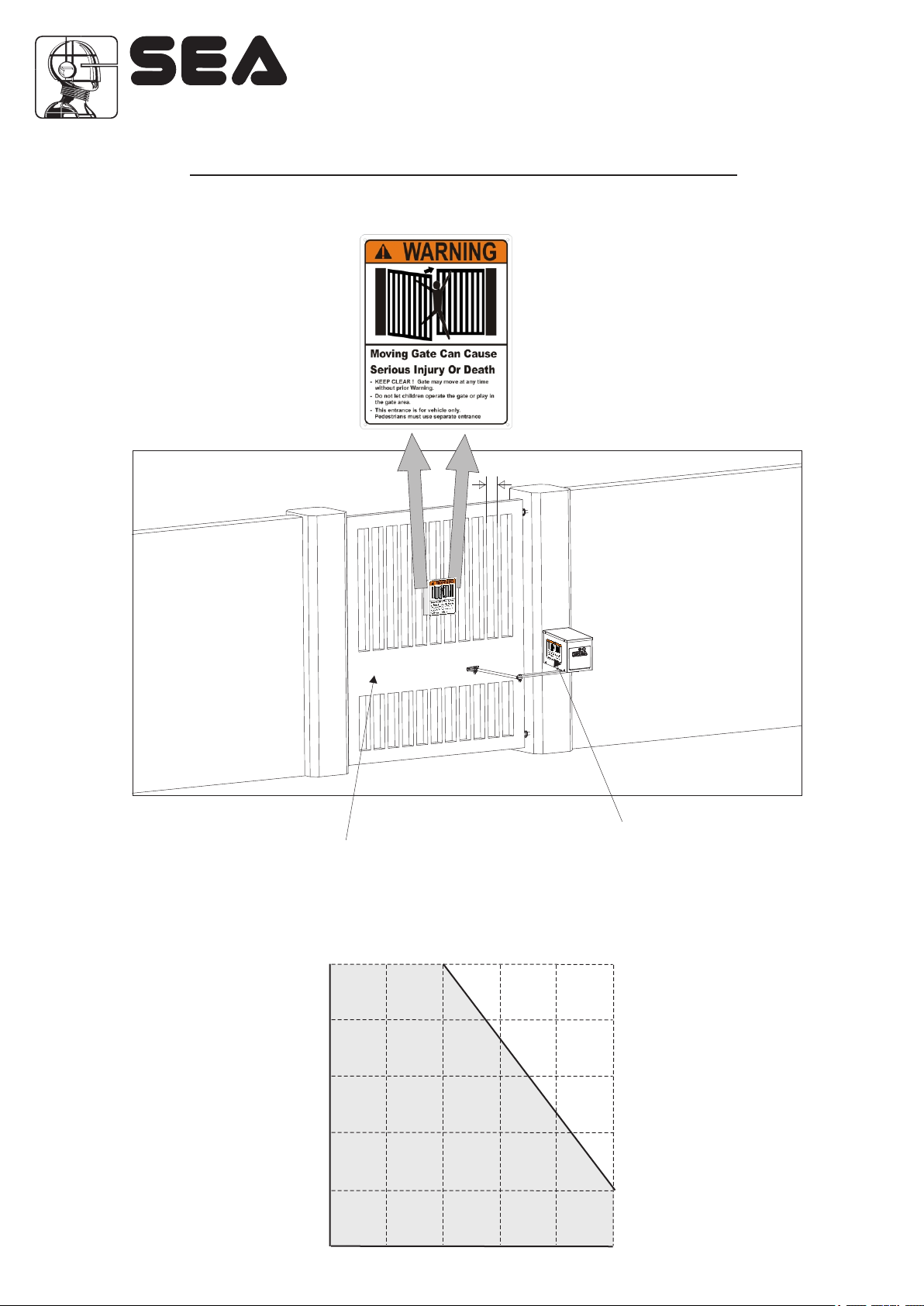
3. Configuration and specification
JOINT
Warning Signs
Attached on
Both Sides of Gate
100 mm Max. Width
Gate Attachment Bar Must Go Completely
Across the Gate for Full Strength
DRAWING LEAVES DIMENSIONS
450 kg
360 kg
270 kg
•
USING
FIELD
180 kg
90 kg
Fig.6
Warning Sign Clearly
Visible on Operator
•
0 lb
6
1,80 m
2,40 m
3,70
5 m
6 m
 Loading...