

SEA GSM-BGS5-E2N User Manual
GSM-BGS5-E2N
If you are using WIN10 and you will use only control via AT commands, do not
download the driver, WIN10 will install its own driver automatically.
1. Introduction
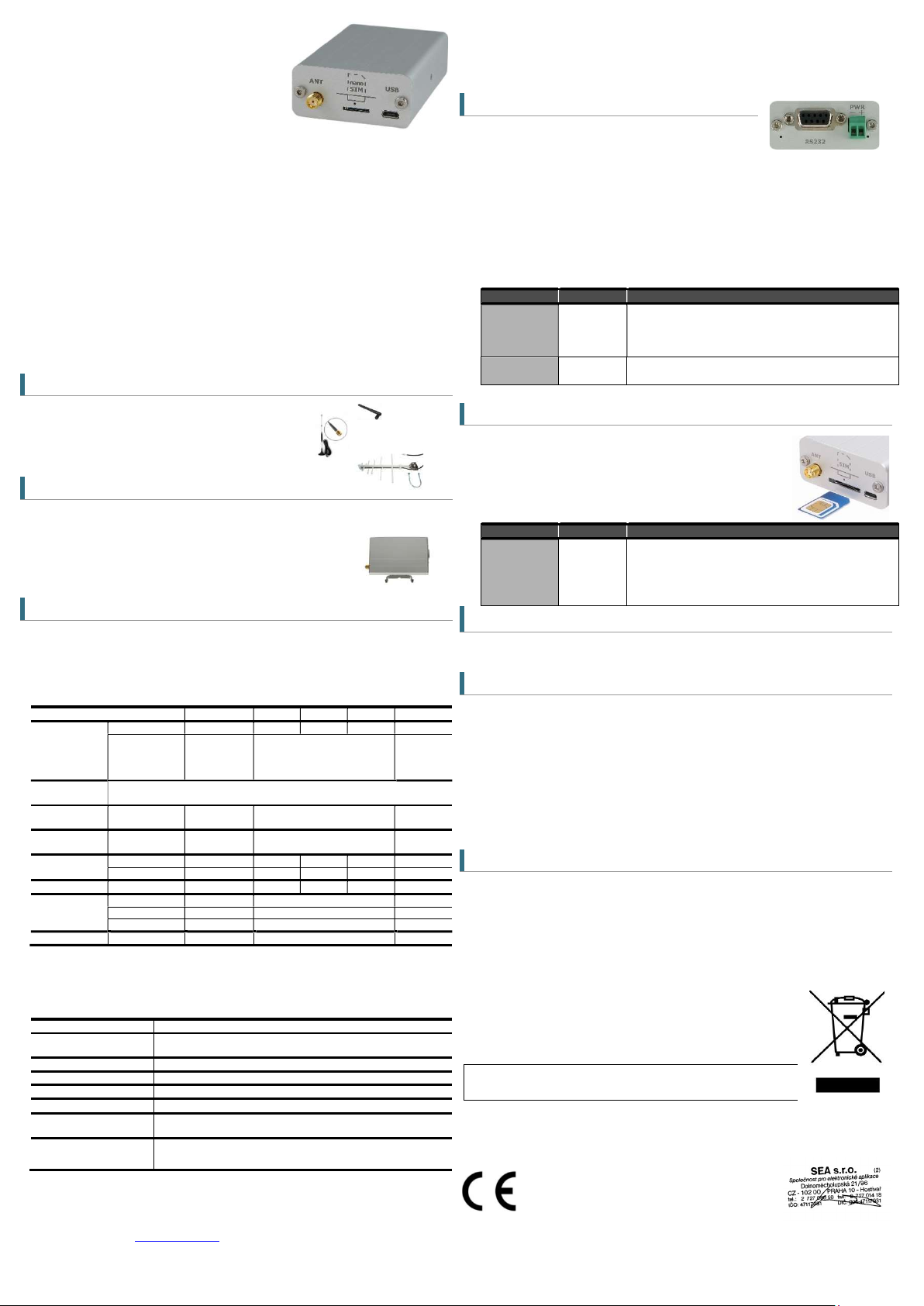
Modem in an industrial metal aluminum case which
is suitable for installation into a control cabinet.
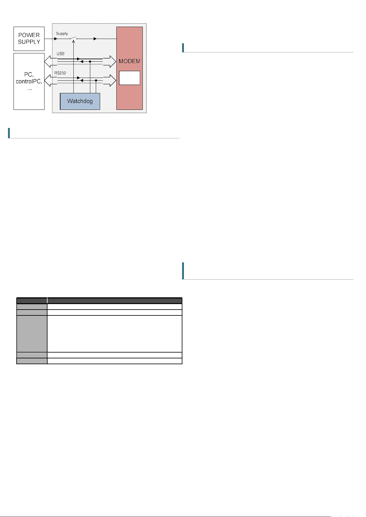
Modem has two communication ports (RS232 and
USB) with adjustable watchdog. The modem is equipped with a GSM module Gemalto
(Cinterion) BGS5 rel.2. Thanks to standard RS232 and USB interface, the modem is
suitable for fast implementation in devices that require remote communication. It also
includes the monitoring of communication with the master device (watchdog), both via
RS232 serial port as well as the USB.
The modem has JAVA OPEN PLATFORM in which you can write your own program, for
example a program for downloading and sending data from connected technology.
For RS232 and USB parameter setting see the chapter 7.4.
Modem can be powered directly from the USB connector.
7. Hardware
7.1 Power supply and it’s indication
Supply voltage is connected to terminals PWR and must be
in the range of 7-33 VDC. The device is protected against
overvoltage and has a built-in refundable SMD fuse. If the external fuse is needed, use
1.25 A fuse at VCC line. As the power consumption from USB is higher than 100mA, it is
sometimes needed to reserve the current or use powered USB hub.
The modem can be powered directly from the USB connector, even using RS232.
If the modem uses power supply from USB cable, the communication is posible only via
USB (not vir RS232. For communication via RS232 you must use external power supply
(GSM-PWR12).
LED PWR is located on the bottom-right side of PWR connector, LED RS232 is located
2. Package Content
1pc GSM modem
1pc 2-pin connector 3,5mm
3. Recommended Accessories
3.1 Antenna
GSM-ANT11K 2dB, Whip jointed antenna, without cable
GSM-ANT01S 5dB, magnetic, cable 3m
GSM-ANT51S 9dB, magnetic, cable 3m
GSM-ANT07S 9,5dB log–per, cable 10m
3.2 Power Supply
GSM-PWR12 Power supply adapter into socket 230V
GSM-PWR1 DIN rail mounted supply module 230VAC / 12VDC, 1.25A
Note: for DIN rail mounting inside of a cabinet suitable:
GSM-75-DIN Plastic DIN rail holder or
GSM-ZIP50 Industrial 3M Dual-Lock ZIP 25x50mm for wall mounting
/ 12VDC, 1A
AC
3.3 Cables
HW-11.99.6218 CANON MD9-FD9 (connected as an extension), length 1.8 m
HW-11.99.8752 USB 2.0 AB (micro USB to a modem), length 1.8m
4. Technical Specification
Parametr Symbol MIN. TYP. MAX. Unit
Voltage DC
Power Supply
(PWR)
POWER
supply conn.
Power supply
via USB
Ingress
Protection
Temperature
Humidity Operating 95 % R.V.
Dimensions
Weight 0.103 kg
Standby power.
consumption
Max. power.
consumption
Voltage
Current
IP 40
Storage tSTG -40 +85 °C
Operating tA -30 +65 °C
Width W 54 mm
Height H 24 mm
Length L 82 mm
connected to
GSM network
(call o GPRS)
2-pin removable screw terminal block, pitch 3.5 mm (PWR),
7 VDC 8 až 30 33 V VDC
0,36 (30mA for 12 VDC)
or micro USB connector
2.1
5
120 360
W
W
mA
V
Note: If the power supply and USB connectors are connected at the same time, current
goes only from power supply connector.
5. Modem Parameters
Parameter Description
GSM , GPRS 12
Antenna connector Device - SMA (F), 50 Ohm
Internet services TCP/UDP server/client, DNS, Ping, FTP client, HTTP client
JAVA 2 MB RAM and 4 MB Flash File System
USB 2.0 Micro USB; USB2.0
RS232
HW watchdog
850/900/1800/1900 MHz
(GPRS 85.6 kbps DL, 85.6 kbps UL)
CANON 9F; 120 to 921600 bps fix bit rate. Autobauding is available.
Factory setting is 115200 baud, 8 data bits, no parity, 1 stop bit
HW Watchdog is available for both RS232 and USB. Note: Watchdog
setting is available only via RS232.
6. Documentation
bottom-left side of RS232 connector.
LED COLOR MEANING
PWR
RS232
green
yellow
dark
convertor is out of order
light
Blinking
… device is not supplied, or internal power
… device in operation state
… communication from the GSM module
7.2 NANO SIM card reader and GSM state indication
Insert the nano SIM card into the holder (cut corner first,
contacts up - towards the inscription SIM). The correct insertion
is indicated by mechanical click noise. Push gently and release
to remove the SIM card.
Above the SIM card holder is located the LED which indicates
status of GSM.
LED COLOR MEANING
Located
above SIM
card holder
SIM
blue
Device state indication.
Dark
… device failure; Device was switched of using
AT command
blinking 1:1
1 short blink per 4 seconds
… device starting up
… device operational
7.3 Antenna
The antenna is connected via SMA connector. The device is fitted with SMA female. The
connected antenna must have SMA male. The impedance is 50 Ω.
7.4 Communication ports (RS232 and micro-USB)
To communicate with the modem (AT commands) is designed interface RS232 and USB.
The device includes a female connector RS232 and micro-USB. The modem can be
controlled using both interfaces, for setting up of the watchdog function is possible to
use only RS232 interface.
Factory default baud rate for communication with the modem for RS232 is 115200bps,
8 data bits, no parity, 1 stop bit. For changing the rate, see the Chapter „RS232
Setting“. Baud rate for USB is not needed to set.
You will see two COM ports in WIN Control panel. For sending AT commands you must
use the port, which you find in Device Manager „Modems“ (Parameters/Modem). Other
port is determined for JAVA application´s development.
7.5 DIN rail mounting
If you need to place the device into the switchboard on DIN rail, screw the plastic holder
GSM-75-DIN drilled hole in the side of the modem.
8. Warranty
General warranty period is 24 months after purchase, when eventual malfunction device will be repaired free of charge in
SEA spol. s r.o. while shipping to SEA is paid by customer and SEA pays for shipping back to custo mer.
The warranty does not cover any damage caused by wrong use whi ch does not comply the technical specifications and
user instructions and any accidental damage (e.g. by water, lightening etc.).
SEA spol. s r.o. has NO RESPONSIBILITY for any damage, lost, costs and any other problems
direct or inducted, caused by device malfunction from any reason.
In case of incompleteness or any damage in the packaging it is necessary to inform SEA spol. s
r.o. immediately (within five days).
in accordance with the Radio and Telecommunications Terminal Equipment Directive
1999/5/EC (R&TTE) and Directive 2011/65/EU (ROHS).
We SEA, spol. s r.o., Dolnoměcholupská 21, CZ 102 00 Praha 10, ID: 47117931 (manufacturer)
declare under our sole responsibility, that product GSM modem with serial ports RS232 a USB type GSM-BGS5-
E2N is in conformity with the following standards:
health and safety: EN 62368-1:2015 + Opr.1:2016 + A11:2017
EMC: EN 301489-1 v2.1.1 EN 301489-52 v1.1.0
radio frequency: EN 301 511 v 12.1.10
CE Declaration of conformity
Place of issue: Praha Name: Ing. Vladimír Rosůlek
Date of issue: 19.7.2018 Grade: director
USB driver (driver for RS232 port is not needed), a list of AT commands and other
information, visit the www.seapraha.cz , type “GSM-BGS5-E2N” into the search box.
In the Name field, enter the text sea. In the Password box, type siemens.
GSM-BGS5-E2N_User_Manual EN v1-29.docx Strana 1 z 2
9. Watchdog setting
BGS5
9.1 RS232
The device contains a built-in watchdog which checks whether the modem answers (if
there are changes in the internal line RxD between GSM module and connected
apliance). If it is no change on the line for specified time period, the modem is
considered broken and is cut off from the power supply for 15 seconds. After that the
modem and monitoring process starts again.
Time, which is still not considered an error of modem is configured using commands via
serial interface RS232. USB port is not possible to use for Watchdog setting!
Factory default is 115200bps, 8 data bits, no parity, 1 stop bit.
Notes:
Before each command must be a time of 1 second when there are no
characters sent!
Characters '-' and '+' in the following examples are sent. '-' … mean Data
are sent to the device, '+' means data are sent by the device.
'<#0D>' is a placeholder for ENTER (13d, 0x0D).
Command ECHO
Display current Watchdog setting
- GSMWDG<#0D>
+ WDG: OK 123456 D2251D v1.0
or
- GSMWDG?<#0D>
+ WDG: OK 123456 D2251D v1.0
Part Description
WDG:
OK
123456
D2251D
V1.0
Watchdog respond identification
Command accepted OK
Actual Watchdog setting value in seconds (HEX code):
123456 HEX = 1 193 046 seconds ~ 13,8 day
000000 HEX = Watchdog function disabled (default setting)
00003C HEX = 60 seconds ~ 1 minute
000E10 HEX = 3 600 seconds ~ 1 hour
008CA0 HEX = 36 000 seconds ~ 10 hours
015180 HEX = 86 400 seconds ~ 1 day
Device Identification
Device version
Command RESET
Immediate modem reset
- GSMWDG RESET<#0D>
+ WDG: OK RESET D2251D v1.0
9.2 USB
USB port has a special circuit for restart of GSM module.
10. RS232 port setting
Baudrate: (AT+IPR)
Parity and data bits: (AT+ICF)
Flow control: (AT\Q)
Factory default setting is made in red bold print.
0 Autobauding
1200
2400
4800
9600
19200
38400
57600
115200 (Factory default)
230400
460800
500000
750000
921600
7 bits, even parity, 1 stop bit (AT+ICF=5,1)
7 bits, odd parity, 1 stop bit (AT+ICF=5,0)
8 bits, even parity, 1 stop bit (AT+ICF=2,1)
8 bits, no parity, 1 stop bit (AT+ICF=3)
8 bits, odd parity, 1 stop bit (AT+ICF=2,0)
8 bits, no parity, 2 stop bits (AT+ICF=1)
No flow control
Software flow control – XON/XOFF
Hardware flow control – RTS/CTS
11. Frequently Asked Question
11.1 Command for Watchdog setting does not
respond
- GSMWDG 52<#0D>
+ <nothing>
The problem is in the assignment of the time "52". It is required to enter the exactly 6-
HEX digits. The correct command is this:
- GSMWDG 000052<#0D>
+ WDG: OK 000052 D2251D v1.0
Command SET
Watchdog setting
- GSMWDG 112233<#0D>
+ WDG: OK 112233 D2251D v1.0
The parameter ‘112233’ means seconds (coded in HEX). See the table for command
ECHO. Exactly 6 HEX numbers has to be entered, including leading zeroes.
Value ‘000000’ disables Watchdog function = modem is never restarted by Watchdog.
Example: Disable Watchdog
- GSMWDG 000000<#0D>
+ WDG: OK 000000 D2251D v1.0
Example: set Watchdog for 1 hour
- GSMWDG 000E10<#0D>
+ WDG: OK 000E10 D2251D v1.0
Example: set Watchdog for 10 hours
- GSMWDG 008CA0<#0D>
+ WDG: OK 008CA0 D2251D v1.0
Example: set Watchdog for 1 day
- GSMWDG 015180<#0D>
+ WDG: OK 015180 D2251D v1.0
GSM-BGS5-E2N_User_Manual EN v1-29.docx Strana 2 z 2
 Loading...